Embed Size (px)
Citation preview
TECHNICAL PAPER
Parametric characterization of piezoelectric valveless micropump
Parikshit Verma • Dhiman Chatterjee
Received: 17 April 2011 / Accepted: 29 September 2011 / Published online: 12 October 2011
� Springer-Verlag 2011
Abstract Experimental investigations are performed to
determine the influence of electrical excitation and geo-
metrical parameters on the performance of piezoelectric
valveless micropumps fabricated on printed circuit board
substrates. Strain gauges and shunt resistor are used in
conjunction with a data acquisition system to form an
effective transducer, capable of providing magnitude and
phase response information pertaining to fluid–structure
interaction. Effect of conical diffuser geometry on the
displacement response and pressure flow characteristics are
studied. With suitable variations in the design of the dif-
fuser element and input excitation parameters, the ability of
the valveless micropump can be extended to include for-
ward, reversed and bidirectional flow features. The char-
acteristic signatures of single and two peaks in flowrate or
pressure data are captured in the displacement phase
response. System identification approach is proposed
to model and predict the performance of valveless
micropumps.
1 Introduction
Micropump forms the essential driving element of any self-
contained microfluidic control system. Among the several
micropumping principles and concepts proposed over the
past two decades, the reciprocating diaphragm valveless
micropumps have been extensively researched due to
high miniaturization potential and a broad range avail-
able in pumping fluids, actuators, substrate materials and
fabrication technologies (Iverson and Garimella 2008;
Laser and Santiago 2004). Increasing application space for
such micropumps is foreseen with integration within
microfuel cells (Zhang and Wang 2005), microelectronic
cooling systems (Singhal and Garimella 2007; Verma et al.
2009) and in the field of biochemistry (Andersson et al.
2001).
Valveless micropumps utilize the oscillating motion of a
vibrating diaphragm to create pressure fluctuations in a
pump chamber and the preferential flow characteristics
inherent in specially shaped conduits for directing the fluid
flow. Stemme and Stemme (1993) introduced the concept
employing diffuser/nozzle conduits for partially rectifying
the flow. Several other conduit shapes have been proposed
since then (Forster et al. 1995; Izzo et al. 2007; Zhang et al.
2007). However, the diffuser/nozzle conduits have been
primarily characterized and commonly studied cross-sec-
tions include conical (Stemme and Stemme 1993), pyra-
midal (Gerlach et al. 1995) and planar (Olsson et al. 1997)
structures. Among these cross-sections, a greater emphasis
has been laid on planar diffusers, due to their compactness
and availability of several existing planar micromachining
techniques. However, unlike the planar diffuser/nozzle
configuration where the flow enters the pump chamber
from both the sides (Shen and Liu 2008), the flow con-
figuration in spatially oriented conical diffuser micropumps
is expected to have stronger interactions with the mem-
brane. This is because the nozzle/diffuser elements are
placed in-line with the transverse displacement direction of
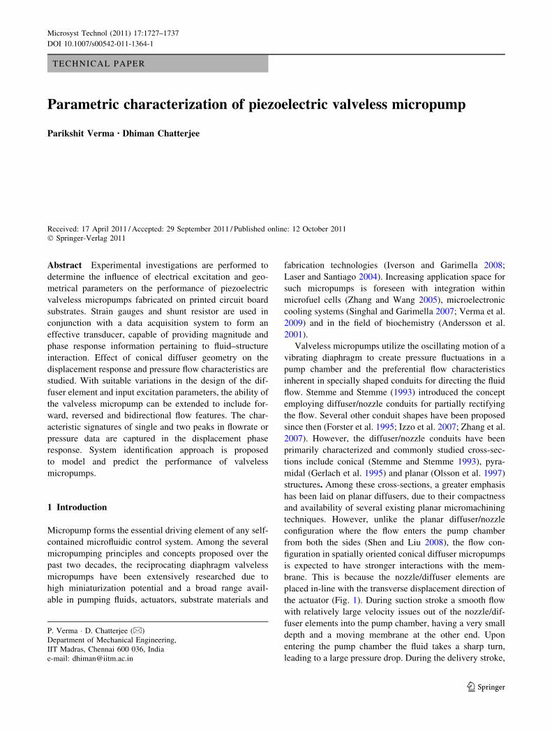
the actuator (Fig. 1). During suction stroke a smooth flow
with relatively large velocity issues out of the nozzle/dif-
fuser elements into the pump chamber, having a very small
depth and a moving membrane at the other end. Upon
entering the pump chamber the fluid takes a sharp turn,
leading to a large pressure drop. During the delivery stroke,
P. Verma � D. Chatterjee (&)
Department of Mechanical Engineering,
IIT Madras, Chennai 600 036, India
e-mail: [email protected]
123
Microsyst Technol (2011) 17:1727–1737
DOI 10.1007/s00542-011-1364-1
flow emanates from the two holes in the pump chamber
into the nozzle/diffuser elements. This differential pressure
in the pump chamber consequently affects the membrane
displacement characteristics at a given input excitation
signal, representing stronger fluid–structure interactions
and this needs to be investigated. The main obstacle faced
in ascertaining this fluid–structure interaction is the
experimental difficulty. Non-contact optical-characteriza-
tion tools, such as digital speckle pattern interferometry,
stroboscopic-interferometry and laser-doppler vibrometery
may be considered for studying this coupled displacement
response. However, these equipments are bulky and
expensive, especially to be used in closed-loop, small
portable systems. Hence, in this work utilization of strain
gauges is proposed and tested for in situ characterization of
the dynamic membrane displacement.
Previous experiments have shown that the performance of
valveless micropumps is primarily dependent on the geo-
metric design of the diffuser/nozzle elements. Nevertheless,
the design of diffusers for micropump applications is still
short of a solid foundation due to lack of relevant experi-
mental data and good analytical expressions for the pressure
loss characteristics in low Reynolds number flow regime
(Wang et al. 2009). Recently, Nabavi (2009) have pointed
out that parametric studies based on microdiffuser geometry
(such as the effect of conical angle or slenderness ratio)
and other flow conditions needs to be carried out experi-
mentally or numerically. Since parametric characteriza-
tion of the performance of valveless micropump using
numerical approaches is computationally very intensive,
other approaches like lumped-parameter or analytical mod-
elling have received considerable attention in the recent past
(Pan et al. 2003; Ullmann and Fono 2002; Bardell et al. 1997;
Hamdan et al. 2010). However, all analytical approaches, to
the best of our knowledge, have assumed pressure inside the
pump chamber to be uniform and have neglected the inter-
action of fluids coming in from nozzle/diffuser into the pump
chamber or vice versa. This is also because of a lack in
available experimental data. Hence in this work different
combinations of diffuser/nozzle and actuator have been used
to ascertain their effects on micropump performance. The
fabrication procedure, experimental setups developed and
adopted methodologies for investigating discrete piezo-
electrically actuated conical diffuser micropumps based on
printed circuit board substrates are detailed in Sects. 2 and 3.
Equivalent circuit modelling approach is then presented in
Sect. 4, followed by a discussion on the obtained results in
Sect. 5. Finally the major conclusions are outlined in Sect. 6.
2 Fabrication of valveless micropump
Printed Circuit Board (PCB) technology is well established
for the integration of electronic systems with special
requirements on reliability and high frequency, such as in
telecommunication and computing equipment. It is also
well suited for the development of fluidic microsystems, as
all the fluidic components can arise within the standard
PCB fabrication process and no separate process steps are
required (Merkel et al. 1999; Nguyen and Huang 2001).
The procedure for the fabrication of valveless micropump
can be divided into the initial production of its constituent
components and thereafter their assembly on fibre glass
boards (FR4). The basic building blocks include a shallow
pump chamber, circular piezoelectric actuator, conical
diffuser/nozzle conduits, plastic connecting tubes and fluid
reservoirs.
The thin copper film on single sided PCB substrate was
structured by wet chemical etching (FeCl3) to form a cir-
cular pump chamber 30 lm in depth. The substrate was
tinned at 270�C to allow ease in soldering the piezoelectric
actuator. Holes were subsequently drilled in the PCB
substrate for fixing the diffuser/nozzle elements. Diffusers
were fabricated by precision micromachining in metal and
plastics. Taper cutting tools were fabricated by grinding in
high speed steel and used for machining the diffusers in
brass and Teflon materials on a watchmakers lathe. The
conical angle of the diffusers of interest was constrained
between 5, 10 and 15�. The length and throat dimensions
were varied for a parametric study to be performed.
Different types of piezoelectric actuators were experi-
mentally characterized (Verma 2011) and based on these
experiments, it was found that commercially available
piezoelectric disk benders (buzzer elements) were most
useful because of their higher relative displacement at a
given excitation input and lower cost. The disk bender
consisted of a piezo ceramic wafer bonded with epoxy
cement to a slightly larger diameter metal disk. The top
surface of the wafer had a thin layer of silver deposited on
it and electrical connections were made by soldering the
lead wires to this layer and the metal disk. Since the
material properties of these buzzer elements were not
known apriori, an inverse method, utilizing simulations
Fig. 1 Principle of operation of piezoelectrically actuated conical
diffuser micropump
1728 Microsyst Technol (2011) 17:1727–1737
123
and experiments, was used to determine the piezoelectric
material used in the buzzer element. Digital Speckle Pat-
tern Interferometry technique was used to find out the
experimental static displacement at variable input voltage.
For the piezoelectric crystal used as an actuator, the
mechanical stress produced is dependent on its material
properties (elasticity, piezoelectricity and permittivity).
Static displacements were then numerically simulated
using ANSYSTM
software for different assumed piezoelec-
tric materials and comparison of the experimental and
numerical results showed that the material properties for
buzzer elements were closest to that of PZT 4.
The discrete components were assembled onto the
pumping chamber etched on the printed circuit board. The
actuator was fixed on the tinned PCB substrates by sol-
dering. This kind of joining mechanism is readily com-
patible with the common soldering operations used in
printed circuit board technology. Fixing by gluing using
epoxy (AralditeTM
) was done for some stainless steel dia-
phragm actuators which were found too difficult to solder
using the tin–lead-based soldering flux. The diffusers were
press fitted into the PCB substrates and flexible plastic
tubes were used to connect the diffuser elements to the
reservoirs and for net pressure-flow measurements. The
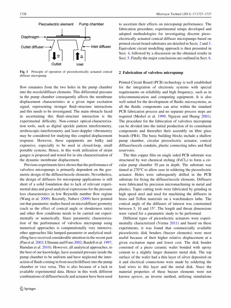
exploded view of the micropump depicting the various
components is shown in Fig. 2a and a typically assembled
prototype used for experimentation is shown in Fig. 2b.
The geometrical dimensions of the components are sum-
marized in Table 1.
3 Experimental setup and methodology
The piezoelectric actuator was driven by a piezo-amplifier
(Spranktronics SN958) which received the drive signal
from a function generator (HP33120A). To cover the
dominant vibration dynamics of the actuator and the
micropump, two sets of frequency sweep signals (chirp
signals) were generated. Frequency sweeps in the range of
40 Hz—1 kHz (termed as low frequency range) were
generated to determine simultaneously the membrane dis-
placement response measured by the strain gauges and
current consumption in air and with liquid loading. For
impedance analysis and determination of the natural fre-
quency of the actuator the input signals were generated in
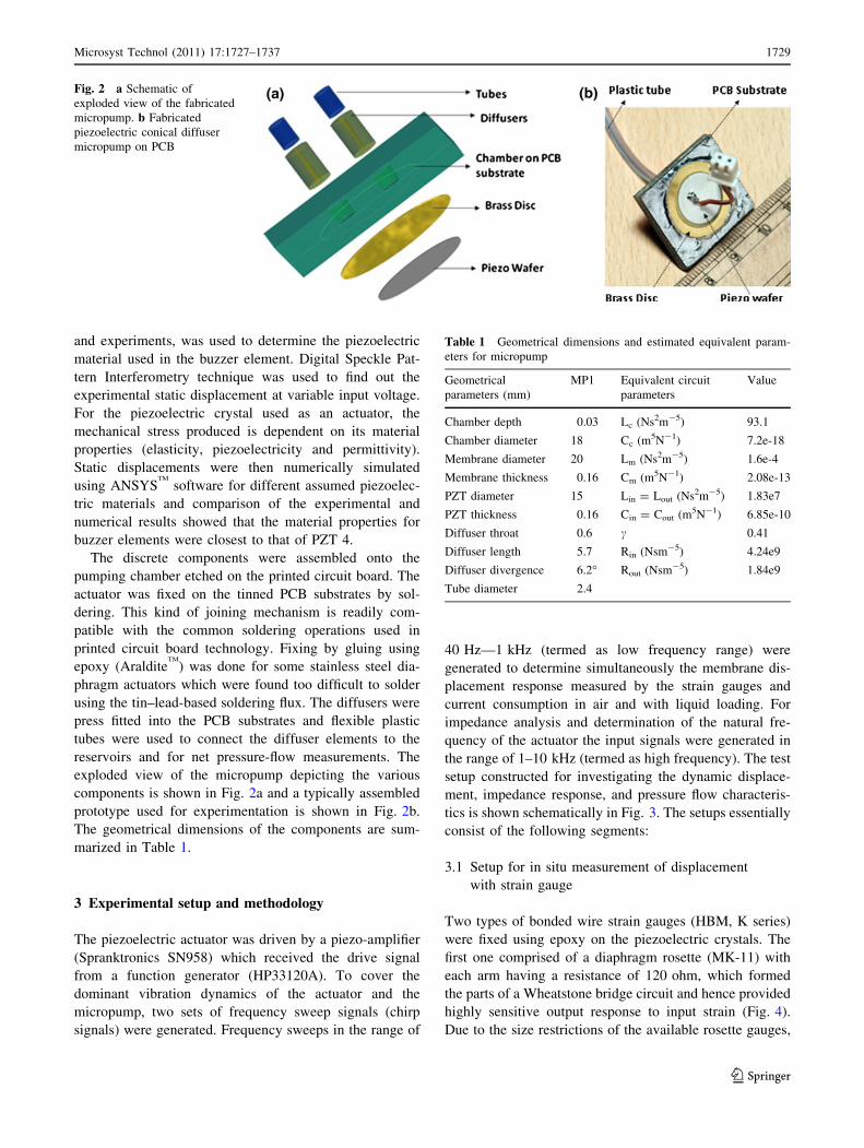
the range of 1–10 kHz (termed as high frequency). The test
setup constructed for investigating the dynamic displace-
ment, impedance response, and pressure flow characteris-
tics is shown schematically in Fig. 3. The setups essentially
consist of the following segments:
3.1 Setup for in situ measurement of displacement
with strain gauge
Two types of bonded wire strain gauges (HBM, K series)
were fixed using epoxy on the piezoelectric crystals. The
first one comprised of a diaphragm rosette (MK-11) with
each arm having a resistance of 120 ohm, which formed
the parts of a Wheatstone bridge circuit and hence provided
highly sensitive output response to input strain (Fig. 4).
Due to the size restrictions of the available rosette gauges,
Fig. 2 a Schematic of
exploded view of the fabricated
micropump. b Fabricated
piezoelectric conical diffuser
micropump on PCB
Table 1 Geometrical dimensions and estimated equivalent param-
eters for micropump
Geometrical
parameters (mm)
MP1 Equivalent circuit
parameters
Value
Chamber depth 0.03 Lc (Ns2m-5) 93.1
Chamber diameter 18 Cc (m5N-1) 7.2e-18
Membrane diameter 20 Lm (Ns2m-5) 1.6e-4
Membrane thickness 0.16 Cm (m5N-1) 2.08e-13
PZT diameter 15 Lin = Lout (Ns2m-5) 1.83e7
PZT thickness 0.16 Cin = Cout (m5N-1) 6.85e-10
Diffuser throat 0.6 c 0.41
Diffuser length 5.7 Rin (Nsm-5) 4.24e9
Diffuser divergence 6.2� Rout (Nsm-5) 1.84e9
Tube diameter 2.4
Microsyst Technol (2011) 17:1727–1737 1729
123
linear single SG (LK 11/13) were also used in smaller-
sized actuators. A half-bridge circuit was formed with a
similar dummy gauge stuck on another actuator. The strain
gauges were connected to a HBM (KWS3073) carrier
frequency amplifier which supplied the input voltage to the
bridge and provided the output voltage corresponding to
the applied strain by the actuator. The output from the
carrier frequency amplifier was acquired via a junction box
(SCB-68) to NITM
data acquisition system (PCI-6259). The
input supply voltages from the function generator and the
piezoelectric amplifier were also acquired in real-time.
LabView 8.2.1TM
was utilized for analyzing and processing
the real-time signals. The device channels were configured
as differential with the sampling frequency always greater
than the Nyquist frequency of operation. Bandpass filters
were used to remove noise in the acquired signals.
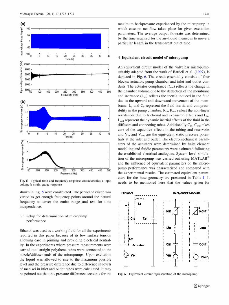
The experimental methodology followed for testing the
micropumps consisted of generating sweep signals at var-
iable input voltages. The typical real-time input voltage
and strain gauge responses for the micropump (whose
details are given in Table 1) at 40 VRMS input are shown in
the top subplots of Fig. 5. The frequency response for both
input signal and strain gauge output were processed in
MATLAB� using Fast Fourier Transforms and is shown in
the bottom subplots of Fig. 5. The top subplots bring out
the differences in the peak to peak amplitude as observed in
the SG voltage output near the natural frequency, relative
to the piezo amplifier output. The response is seen to be flat
within the tested range of operations for the input voltage
as is expected and increased around 150 Hz for the output
from strain gauge due to increase in displacement of the
actuator. The implications of these findings are discussed in
Sect. 5 along with the Bode diagrams constructed to study
the phase and magnitude information and for investigating
the influence of geometry.
3.2 Setup for performing impedance analysis
Determination of capacitive behaviour of the actuator and
power consumption is necessary to optimize the system
configuration and to design efficient drive electronics for
control. Also, the natural frequency of the piezoelectric-
diaphragm structure should be identified to study how it
affects the performance of the micropump. Since the
electrical impedance of the piezoceramic material drops to
a local minimum when it vibrates at the resonant fre-
quency, a shunt resistor (33 X) was utilized to study this
effect. It was attached in series with the piezoelectric
actuator, Fig. 3, and provided the current information and
showed the electromechanical resonant behaviour of the
actuator. Sweeping procedures similar to that described in
connection with strain gauge measurements (Sect. 3.1)
were followed and frequency response plots similar to that
Fig. 3 Schematic of experimental setup utilized for micropump characterization
Fig. 4 Representative picture of rosette type strain gauge fixed on
the piezoelectric actuator
1730 Microsyst Technol (2011) 17:1727–1737
123
shown in Fig. 5 were constructed. The period of sweep was
varied to get enough frequency points around the natural
frequency to cover the entire range and test for time
independence.
3.3 Setup for determination of micropump
performance
Ethanol was used as a working fluid for all the experiments
reported in this paper because of its low surface tension
allowing ease in priming and providing electrical neutral-
ity. In the experiments where pressure measurements were
carried out, straight polythene tubes were connected to the
nozzle/diffuser ends of the micropumps. Upon excitation
the liquid was allowed to rise to the maximum possible
level and the pressure difference due to difference in levels
of menisci in inlet and outlet tubes were calculated. It may
be pointed out that this pressure difference accounts for the
maximum backpressure experienced by the micropump in
which case no net flow takes place for given excitation
parameters. The average output flowrate was determined
by the time required for the air–liquid meniscus to move a
particular length in the transparent outlet tube.
4 Equivalent circuit model of micropump
An equivalent circuit model of the valveless micropump,
suitably adapted from the work of Bardell et al. (1997), is
depicted in Fig. 6. The circuit essentially consists of four
blocks: actuator, pump chamber and inlet and outlet con-
duits. The actuator compliance (Cm) reflects the change in
the chamber volume due to the deflection of the membrane
and inertance (Lm) reflects the inertia induced in the fluid
due to the upward and downward movement of the mem-
brane. Lc and Cc represent the fluid inertia and compress-
ibility in the pump chamber. Rin, Rout reflect the non-linear
resistances due to frictional and expansion effects and Lin,
Lout represent the dynamic inertial effects of the fluid in the
diffusers and connecting tubes. Additionally Cin, Cout takes
care of the capacitive effects in the tubing and reservoirs
and Vin and Vout are the equivalent static pressure poten-
tials at the inlet and outlet. The electromechanical param-
eters of the actuators were determined by finite element
modelling and fluidic parameters were estimated following
the established electrical analogues. System level simula-
tion of the micropump was carried out using MATLAB�
and the influence of equivalent parameters on the micro-
pump performance was characterized and compared with
the experimental results. The estimated equivalent param-
eters for the base geometry are presented in Table 1. It
needs to be mentioned here that the values given forFig. 5 Typical time and frequency response characteristics a input
voltage b strain gauge response
Fig. 6 Equivalent circuit representation of the micropump
Microsyst Technol (2011) 17:1727–1737 1731
123
resistances (Rin and Rout) are not only function of geometry
but also flowrate and hence the resistance values are only
representative in nature.
5 Results and discussion
Complete characterization of a valveless micropump
involves determining actuator characteristics, fluid–struc-
ture interaction in the micropump and its hydraulic per-
formance. The results are presented along these lines in the
following sections.
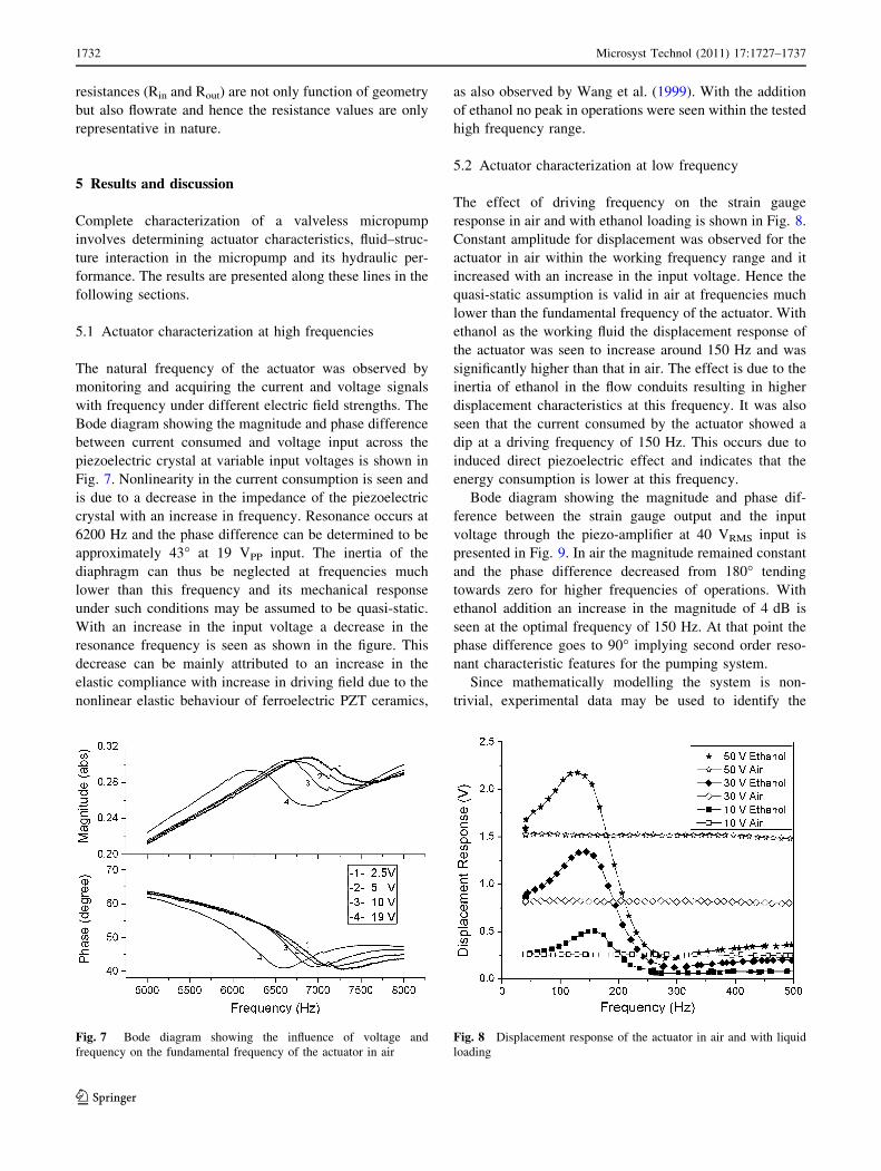
5.1 Actuator characterization at high frequencies
The natural frequency of the actuator was observed by
monitoring and acquiring the current and voltage signals
with frequency under different electric field strengths. The
Bode diagram showing the magnitude and phase difference
between current consumed and voltage input across the
piezoelectric crystal at variable input voltages is shown in
Fig. 7. Nonlinearity in the current consumption is seen and
is due to a decrease in the impedance of the piezoelectric
crystal with an increase in frequency. Resonance occurs at
6200 Hz and the phase difference can be determined to be
approximately 43� at 19 VPP input. The inertia of the
diaphragm can thus be neglected at frequencies much
lower than this frequency and its mechanical response
under such conditions may be assumed to be quasi-static.
With an increase in the input voltage a decrease in the
resonance frequency is seen as shown in the figure. This
decrease can be mainly attributed to an increase in the
elastic compliance with increase in driving field due to the
nonlinear elastic behaviour of ferroelectric PZT ceramics,
as also observed by Wang et al. (1999). With the addition
of ethanol no peak in operations were seen within the tested
high frequency range.
5.2 Actuator characterization at low frequency
The effect of driving frequency on the strain gauge
response in air and with ethanol loading is shown in Fig. 8.
Constant amplitude for displacement was observed for the
actuator in air within the working frequency range and it
increased with an increase in the input voltage. Hence the
quasi-static assumption is valid in air at frequencies much
lower than the fundamental frequency of the actuator. With
ethanol as the working fluid the displacement response of
the actuator was seen to increase around 150 Hz and was
significantly higher than that in air. The effect is due to the
inertia of ethanol in the flow conduits resulting in higher
displacement characteristics at this frequency. It was also
seen that the current consumed by the actuator showed a
dip at a driving frequency of 150 Hz. This occurs due to
induced direct piezoelectric effect and indicates that the
energy consumption is lower at this frequency.
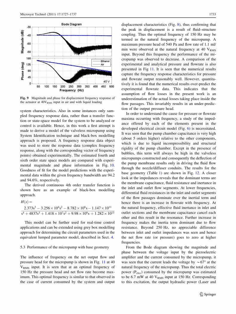
Bode diagram showing the magnitude and phase dif-
ference between the strain gauge output and the input
voltage through the piezo-amplifier at 40 VRMS input is
presented in Fig. 9. In air the magnitude remained constant
and the phase difference decreased from 180� tending
towards zero for higher frequencies of operations. With
ethanol addition an increase in the magnitude of 4 dB is
seen at the optimal frequency of 150 Hz. At that point the
phase difference goes to 90� implying second order reso-
nant characteristic features for the pumping system.
Since mathematically modelling the system is non-
trivial, experimental data may be used to identify the
Fig. 7 Bode diagram showing the influence of voltage and
frequency on the fundamental frequency of the actuator in air
Fig. 8 Displacement response of the actuator in air and with liquid
loading
1732 Microsyst Technol (2011) 17:1727–1737
123
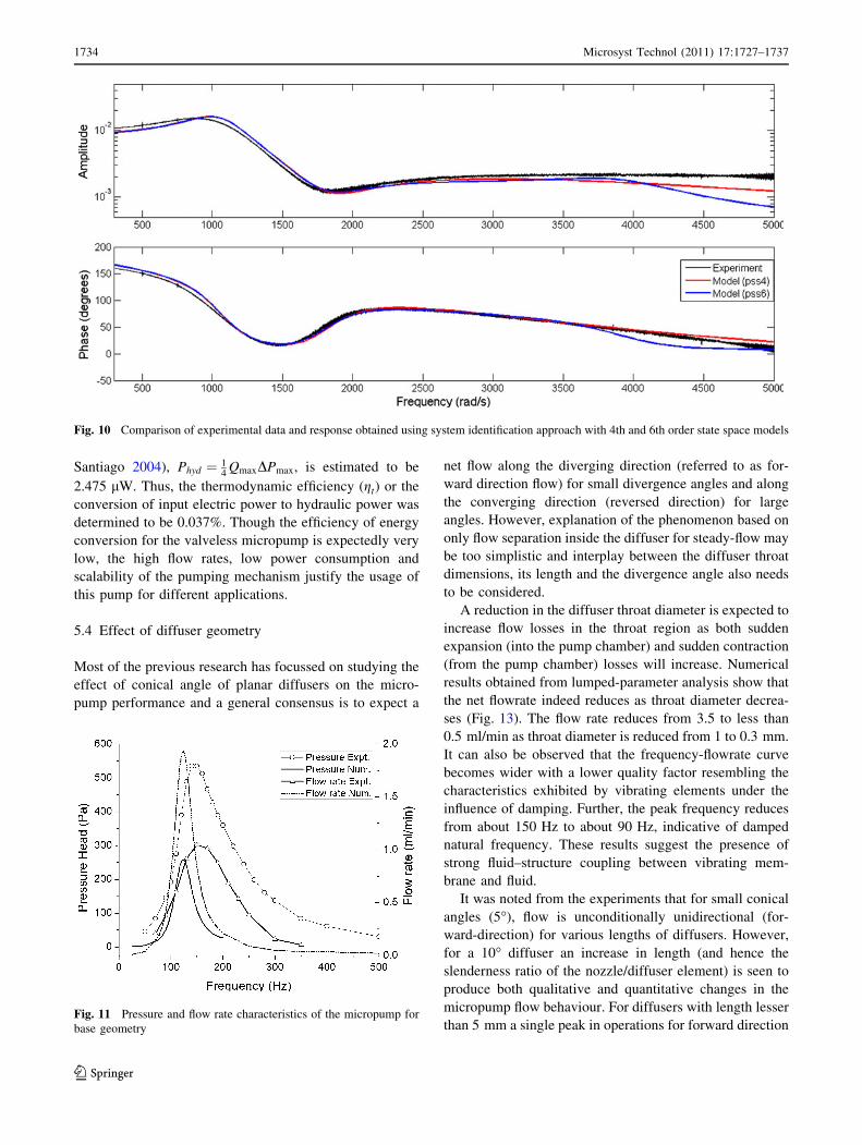
system characteristics. Also in some instances only sam-
pled frequency response data, rather than a transfer func-
tion or state-space model for the system to be analyzed or
control is available. Hence, in this work a first attempt is
made to derive a model of the valveless micropump using
System Identification technique and black-box modelling
approach is proposed. A frequency response data object
was used to store the response data (complex frequency
response, along with the corresponding vector of frequency
points) obtained experimentally. The estimated fourth and
sixth order state space models are compared with experi-
mental magnitude and phase information in Fig. 10.
Goodness of fit for the model predictions with the experi-
mental data within the given frequency bandwidth are 94.2
and 94.6%, respectively.
The derived continuous 4th order transfer function is
shown here as an example of black-box modelling
approach.
HðsÞ¼2:373s3 � 3:256�104s2 � 8:782�106s� 1:147�1011
s4 þ 4837s3 þ 1:418�107s2 þ 9:98�109s þ 1:282�1013
This model can be further used for real-time control
applications and can be extended using grey box modelling
approach for determining the circuit parameters used in the
equivalent lumped parameter model, described in Sect. 4.
5.3 Performance of the micropump with base geometry
The influence of frequency on the net output flow and
pressure head for the micropump is shown in Fig. 11 at 40
VRMS input. It is seen that at an optimal frequency of
150 Hz the pressure head and net flow rate become max-
imum. This optimal frequency is similar to that observed in
the case of current consumed by the system and output
displacement characteristics (Fig. 8), thus confirming that
the peak in displacement is a result of fluid–structure
coupling. Thus the optimal frequency of 150 Hz may be
termed as the natural frequency of the micropump. A
maximum pressure head of 540 Pa and flow rate of 1.1 ml/
min were observed at the natural frequency at 40 VRMS
input. Beyond this frequency the performance of the mi-
cropump was observed to decrease. A comparison of the
experimental and analytical pressure and flowrate is also
presented in Fig 11. It is seen that the numerical results
capture the frequency response characteristics for pressure
and flowrate output reasonably well. However, quantita-
tively it is found that the numerical results over-predict the
experimental flowrate data. This indicates that the
assumption of flow losses in the present work is an
underestimation of the actual losses taking place inside the
flow passages. This invariably results in an under-predic-
tion of the output pressure head.
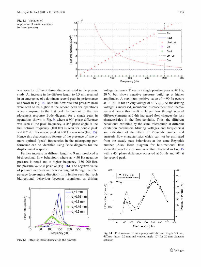
In order to understand the cause for pressure or flowrate
maxima occurring with frequency, a study of the imped-
ance offered by each of the elements present in the
developed electrical circuit model (Fig. 6) is necessitated.
It was seen that the pump chamber capacitance is very high
(about 5 orders higher) relative to the other components,
which is due to liquid incompressibility and structural
rigidity of the pump chamber. Except in the presence of
bubbles, this term will always be high in the valveless
micropumps constructed and consequently the deflection of
the pump membrane results only in driving the fluid flow
through the nozzle/diffuser conduits. The results for the
base geometry (Table 1) are shown in Fig. 12. A closer
look at the impedances reveals that the dominant terms are
the membrane capacitance, fluid resistance and inertance in
the inlet and outlet flow segments. At lower frequencies,
differential fluid resistances in the inlet and outlet segments
of the flow passages dominate over the inertial term and
hence there is an increase in flowrate with frequency. At
the natural frequency, effective fluid inertance in inlet and
outlet sections and the membrane capacitance cancel each
other and this result in the resonance. Further increase in
frequency makes the inertia term dominant due to flow
resistance. Beyond 250 Hz, no appreciable difference
between inlet and outlet impedances was seen and hence
the net flow rate (or pressure) goes to zero at higher
frequencies.
From the Bode diagram showing the magnitude and
phase between the voltage input by the piezoelectric
amplifier and the current consumed by the micropump, it
was seen that the current leads the voltage by *67� at the
natural frequency of the micropump. Thus the total electric
power (Pelec) consumed by the micropump was estimated
to be 6.7 mW at 40 VRMS input at 150 Hz. Corresponding
to this excitation, the output hydraulic power (Laser and
Fig. 9 Magnitude and phase for displacement frequency response of
the actuator at 40VRMS input in air and with liquid loading
Microsyst Technol (2011) 17:1727–1737 1733
123
Santiago 2004), Phyd ¼ 14
QmaxDPmax, is estimated to be
2.475 lW. Thus, the thermodynamic efficiency (gt) or the
conversion of input electric power to hydraulic power was
determined to be 0.037%. Though the efficiency of energy
conversion for the valveless micropump is expectedly very
low, the high flow rates, low power consumption and
scalability of the pumping mechanism justify the usage of
this pump for different applications.
5.4 Effect of diffuser geometry
Most of the previous research has focussed on studying the
effect of conical angle of planar diffusers on the micro-
pump performance and a general consensus is to expect a
net flow along the diverging direction (referred to as for-
ward direction flow) for small divergence angles and along
the converging direction (reversed direction) for large
angles. However, explanation of the phenomenon based on
only flow separation inside the diffuser for steady-flow may
be too simplistic and interplay between the diffuser throat
dimensions, its length and the divergence angle also needs
to be considered.
A reduction in the diffuser throat diameter is expected to
increase flow losses in the throat region as both sudden
expansion (into the pump chamber) and sudden contraction
(from the pump chamber) losses will increase. Numerical
results obtained from lumped-parameter analysis show that
the net flowrate indeed reduces as throat diameter decrea-
ses (Fig. 13). The flow rate reduces from 3.5 to less than
0.5 ml/min as throat diameter is reduced from 1 to 0.3 mm.
It can also be observed that the frequency-flowrate curve
becomes wider with a lower quality factor resembling the
characteristics exhibited by vibrating elements under the
influence of damping. Further, the peak frequency reduces
from about 150 Hz to about 90 Hz, indicative of damped
natural frequency. These results suggest the presence of
strong fluid–structure coupling between vibrating mem-
brane and fluid.
It was noted from the experiments that for small conical
angles (5�), flow is unconditionally unidirectional (for-
ward-direction) for various lengths of diffusers. However,
for a 10� diffuser an increase in length (and hence the
slenderness ratio of the nozzle/diffuser element) is seen to
produce both qualitative and quantitative changes in the
micropump flow behaviour. For diffusers with length lesser
than 5 mm a single peak in operations for forward direction
Fig. 10 Comparison of experimental data and response obtained using system identification approach with 4th and 6th order state space models
Fig. 11 Pressure and flow rate characteristics of the micropump for
base geometry
1734 Microsyst Technol (2011) 17:1727–1737
123
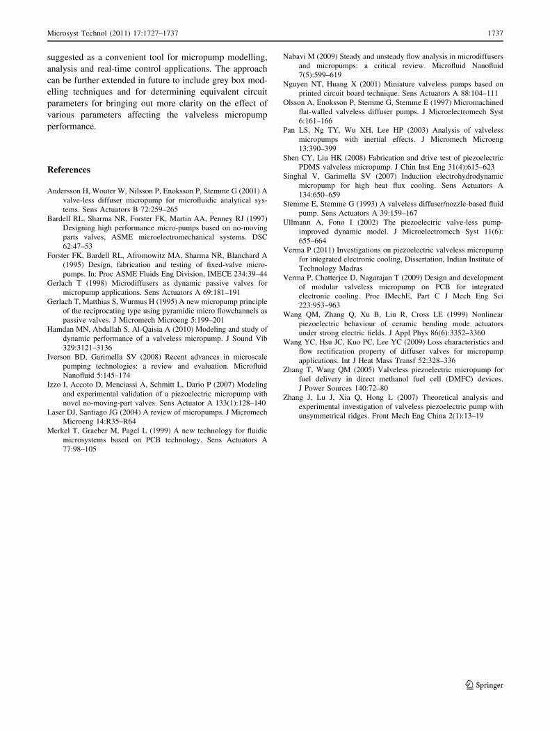
was seen for different throat diameters used in the present
study. An increase in the diffuser length to 5.3 mm resulted
in an emergence of a dominant second peak in performance
as shown in Fig. 14. Both the flow rate and pressure head
were seen to be higher at the second peak for operations
when compared to the first peak. In contrast to the dis-
placement response Bode diagram for a single peak in
operations shown in Fig. 9, where a 90� phase difference
was seen at the peak frequency, a 45� phase angle at the
first optimal frequency (100 Hz) is seen for double peak
and 90� shift for second peak at 450 Hz was seen (Fig. 15).
Hence this characteristic feature of the presence of two or
more optimal (peak) frequencies in the micropump per-
formance can be identified using Bode diagrams for the
displacement response.
Further increase in diffuser length to 9 mm produced a
bi-directional flow behaviour, where at *50 Hz negative
pressure is noted and at higher frequency (150–200 Hz),
the pressure value is positive (Fig. 16). The negative value
of pressure indicates net flow coming out through the inlet
passage (converging direction). It is further seen that such
bidirectional behaviour becomes prominent as driving
voltage increases. There is a single positive peak at 40 Hz,
20 V, but shows negative pressure build up at higher
amplitudes. A maximum positive value of *90 Pa occurs
at *100 Hz for driving voltage of 40 VRMS. As the driving
voltage is increased, membrane displacement also increa-
ses and hence this result in larger flow through nozzle/
diffuser elements and this increased flow changes the loss
characteristics in the flow-conduits. Thus, the different
behaviours exhibited by the same micropump at different
excitation parameters (driving voltages and frequencies)
are indicative of the effect of Reynolds number and
unsteady flow characteristics which can not be estimated
from the steady state behaviours at the same Reynolds
number. Also, Bode diagram for bi-directional flow
showed characteristics similar to that observed in Fig. 15
with a 45� phase difference observed at 50 Hz and 90� at
the second peak.
Fig. 12 Variation of
impedance of circuit elements
for base geometry
Fig. 13 Effect of throat diameter on the flowrate
Fig. 14 Performance of micropump with diffuser length 5.3 mm,
diffuser throat 0.6 mm and conical angle 10� for 20 mm diameter
actuator
Microsyst Technol (2011) 17:1727–1737 1735
123
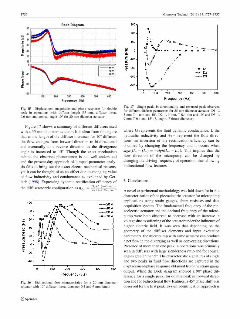
Figure 17 shows a summary of different diffusers used
with a 35 mm diameter actuator. It is clear from this figure
that as the length of the diffuser increases for 10� diffuser,
the flow changes from forward direction to bi-directional
and eventually to a reverse direction as the divergence
angle is increased to 15�. Though the exact mechanism
behind the observed phenomenon is not well-understood
and the present-day approach of lumped-parameter analy-
sis fails to bring out the exact electro-mechanical reasons,
yet it can be thought of as an effect due to changing value
of flow inductivity and conductance as explained by Ger-
lach (1998). Expressing dynamic rectification efficiency of
the diffuser/nozzle configuration as gdyn ¼ðGþþLþÞ�ðG�þL�ÞðGþþLþÞþðG�þL�Þ,
where G represents the fluid dynamic conductance, L the
hydraulic inductivity and ?/- represent the flow direc-
tions; an inversion of the rectification efficiency can be
obtained by changing the frequency and it occurs when
signðGþ � G�Þ ¼ �signðL� � LþÞ. This implies that the
flow direction of the micropump can be changed by
changing the driving frequency of operation, thus allowing
bidirectional flow features.
6 Conclusions
A novel experimental methodology was laid down for in situ
characterization of the piezoelectric actuator for micropump
applications using strain gauges, shunt resistors and data
acquisition system. The fundamental frequency of the pie-
zoelectric actuator and the optimal frequency of the micro-
pump were both observed to decrease with an increase in
voltage due to softening of the actuator under the influence of
higher electric field. It was seen that depending on the
geometry of the diffuser elements and input excitation
parameters, the micropump with same actuator can produce
a net flow in the diverging as well as converging directions.
Presence of more than one peak in operations was primarily
seen in diffusers with large slenderness ratio and for conical
angles greater than 5�. The characteristic signatures of single
and two peaks in fluid flow directions are captured in the
displacement-phase response obtained from the strain gauge
output. While the Bode diagram showed a 90� phase dif-
ference for a single peak, for double peak in forward direc-
tion and for bidirectional flow features, a 45� phase shift was
observed for the first peak. System identification approach is
Fig. 15 Displacement magnitude and phase response for double
peak in operations with diffuser length 5.3 mm, diffuser throat
0.6 mm and conical angle 10� for 20 mm diameter actuator
Fig. 16 Bidirectional flow characteristics for a 20 mm diameter
actuator with 10� diffuser, throat diameter 0.4 and 9 mm length
Fig. 17 Single-peak, bi-directionality and reversed peak observed
for different diffuser geometries for 35 mm diameter actuator. D1: L
5 mm T 1 mm and 10�, D2: L 9 mm, T 0.4 mm and 10� and D3: L
9 mm T 0.4 and 15� (L length, T throat diameter)
1736 Microsyst Technol (2011) 17:1727–1737
123
suggested as a convenient tool for micropump modelling,
analysis and real-time control applications. The approach
can be further extended in future to include grey box mod-
elling techniques and for determining equivalent circuit
parameters for bringing out more clarity on the effect of
various parameters affecting the valveless micropump
performance.
References
Andersson H, Wouter W, Nilsson P, Enoksson P, Stemme G (2001) A
valve-less diffuser micropump for microfluidic analytical sys-
tems. Sens Actuators B 72:259–265
Bardell RL, Sharma NR, Forster FK, Martin AA, Penney RJ (1997)
Designing high performance micro-pumps based on no-moving
parts valves, ASME microelectromechanical systems. DSC
62:47–53
Forster FK, Bardell RL, Afromowitz MA, Sharma NR, Blanchard A
(1995) Design, fabrication and testing of fixed-valve micro-
pumps. In: Proc ASME Fluids Eng Division, IMECE 234:39–44
Gerlach T (1998) Microdiffusers as dynamic passive valves for
micropump applications. Sens Actuators A 69:181–191
Gerlach T, Matthias S, Wurmus H (1995) A new micropump principle
of the reciprocating type using pyramidic micro flowchannels as
passive valves. J Micromech Microeng 5:199–201
Hamdan MN, Abdallah S, Al-Qaisia A (2010) Modeling and study of
dynamic performance of a valveless micropump. J Sound Vib
329:3121–3136
Iverson BD, Garimella SV (2008) Recent advances in microscale
pumping technologies: a review and evaluation. Microfluid
Nanofluid 5:145–174
Izzo I, Accoto D, Menciassi A, Schmitt L, Dario P (2007) Modeling
and experimental validation of a piezoelectric micropump with
novel no-moving-part valves. Sens Actuator A 133(1):128–140
Laser DJ, Santiago JG (2004) A review of micropumps. J Micromech
Microeng 14:R35–R64
Merkel T, Graeber M, Pagel L (1999) A new technology for fluidic
microsystems based on PCB technology. Sens Actuators A
77:98–105
Nabavi M (2009) Steady and unsteady flow analysis in microdiffusers
and micropumps: a critical review. Microfluid Nanofluid
7(5):599–619
Nguyen NT, Huang X (2001) Miniature valveless pumps based on
printed circuit board technique. Sens Actuators A 88:104–111
Olsson A, Enoksson P, Stemme G, Stemme E (1997) Micromachined
flat-walled valveless diffuser pumps. J Microelectromech Syst
6:161–166
Pan LS, Ng TY, Wu XH, Lee HP (2003) Analysis of valveless
micropumps with inertial effects. J Micromech Microeng
13:390–399
Shen CY, Liu HK (2008) Fabrication and drive test of piezoelectric
PDMS valveless micropump. J Chin Inst Eng 31(4):615–623
Singhal V, Garimella SV (2007) Induction electrohydrodynamic
micropump for high heat flux cooling. Sens Actuators A
134:650–659
Stemme E, Stemme G (1993) A valveless diffuser/nozzle-based fluid
pump. Sens Actuators A 39:159–167
Ullmann A, Fono I (2002) The piezoelectric valve-less pump-
improved dynamic model. J Microelectromech Syst 11(6):
655–664
Verma P (2011) Investigations on piezoelectric valveless micropump
for integrated electronic cooling, Dissertation, Indian Institute of
Technology Madras
Verma P, Chatterjee D, Nagarajan T (2009) Design and development
of modular valveless micropump on PCB for integrated
electronic cooling. Proc IMechE, Part C J Mech Eng Sci
223:953–963
Wang QM, Zhang Q, Xu B, Liu R, Cross LE (1999) Nonlinear
piezoelectric behaviour of ceramic bending mode actuators
under strong electric fields. J Appl Phys 86(6):3352–3360
Wang YC, Hsu JC, Kuo PC, Lee YC (2009) Loss characteristics and
flow rectification property of diffuser valves for micropump
applications. Int J Heat Mass Transf 52:328–336
Zhang T, Wang QM (2005) Valveless piezoelectric micropump for
fuel delivery in direct methanol fuel cell (DMFC) devices.
J Power Sources 140:72–80
Zhang J, Lu J, Xia Q, Hong L (2007) Theoretical analysis and
experimental investigation of valveless piezoelectric pump with
unsymmetrical ridges. Front Mech Eng China 2(1):13–19
Microsyst Technol (2011) 17:1727–1737 1737
123


![Copyright · Jamil, Mohammad, Qatar University, Qatar ... Iman Shahosseini, ... et al. developed a valveless micropump [3], in which](https://img.pdfslide.us/doc/110x75/5b697af67f8b9adc178e71f3/-jamil-mohammad-qatar-university-qatar-iman-shahosseini-et-al-developed.jpg)