Embed Size (px)
Citation preview
International Research Journal of Applied and Basic Sciences © 2013 Available online at www.irjabs.com ISSN 2251-838X / Vol, 6 (7): 901-909 Science Explorer Publications
Parametric and Two Dimensional Study of seismic behavior of micropile Group in Sandy Soils
Vahid Maghsoodi1, Farshad Atermoghaddam2, Mahzad Esmaeili-Falak3
1. Assistant Professor of School of Civil Engineering, University of Tafresh.
2. Master of Civil - Geotechnical Engineering, University of Tafresh. 3. Department of Civil Engineering, East Azarbaijan, Science and Research Branch, Islamic Azad University,
Tabriz, Iran.
Corresponding Author email: [email protected]
ABSTRACT: This paper examines the effects of acceleration amplitude of harmonic seismic load and damping ratio on seismic behavior ofmicropile group. A two dimensionalfinite element model and plain strain in Plaxis software have been used for modeling. Sandy soil is considered elastically and with and without Rayleigh damping. Substructure is modeled with a single freedom degree system composed of concentrated mass and a column. Micropiles are considered in vertical position. Analysis results show that increase in amplitude of input acceleration also causes, approximately at the same proportion, increase in shift, horizontal and vertical acceleration cap. Increase in seismic harmonic load amplitude, also causes increase in the amounts of bending moment, shear and axial force of micropiles. Rayleigh damping ratio causes energy to be depreciated during loading stage and it causes decrease in the amount of force transmission into structure. Damping causes 250% decrease in cap displacement. Rayleigh damping ratio causes slight decrease in vertical acceleration of micropile cap. However, it causes considerable reduction in horizontal acceleration of the cap so that horizontal acceleration of the cap for without damping case is more than fourfold of damping case. Keywords: micropile, seismic, harmonic, acceleration, damping ratio
INTRODUCTION
Micropile was developed in Italy in 1950 for the first time as an innovative method for underpinning of historical and commemorative buildings that over time and especially during World War II had been damaged. There was a need for an effective and reliable underpinning system as a support for structural loads using minimal displacement that would be applicable in the limited and difficult to access places, and to create minimal disturbance in existing structures. Micropiles are piles with diameters less than 300 mm that are implemented through borehole drillings, placement of reinforcement, grout injection (Atermoghadam, F., 2012). Special methods for drilling and injection that are used in implementing the micropiles cause creation of resistant connectivity between grout and soil and this causes increase in bearing capacity on interface between the ground and the grout. Injected grout transmits the applied load to micropile via friction from rebar to the earth at connection area (FHWA, 2000). Micropiles are used as anchors for foundation of new structures in seismic areas and also for retrofitting the structures that have been damaged due to seismic hazards. According to the experiments, due to the high flexibility micropiles show appropriate behavior under seismic load. However, up to now enough and appropriate studies have not been done on real scales, and studying dynamic behavior of micropiles seems necessary and this, causes to make the use of numerical analysis like finite elements method in studying the behavior of micropiles during the earthquakes. In this regard finite element software has been used to do dynamic analysis. Substantially, numerical model shows that seismic load creates internal force on flexible micropiles that are used as foundation anchors. The present research, studies the effect of acceleration amplitude of harmonic seismic load and Rayleigh damping ratio on seismic behavior of micropile groupand in this regard, harmonic seismic load has been used. This research shows the importance of the effect of input acceleration peak of seismic harmonic loads and Rayleigh damping ratio on seismic behavior of micropile group (FHWA, 2005).
Intl. Res. J. Appl. Basic. Sci. Vol., 6 (7), 901-909, 2013
902
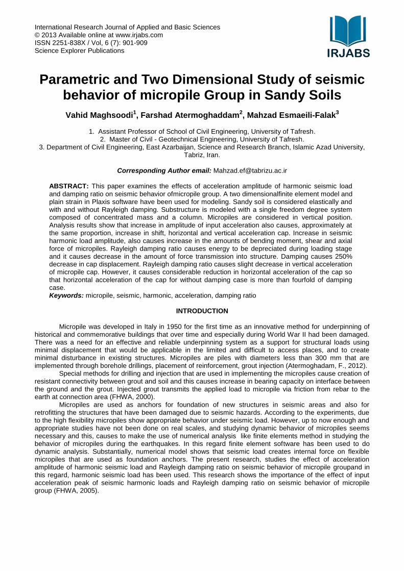
Numerical Modeling of Structure-Soil-Micropile interaction Numerical modeling has been used to do dynamic analysis using finite element Plaxis
2Dver8.2 software
which enjoys two dimensional modeling in the form of plain-strain. Soil behavior using is described using linear elastic model. Micropiles are modeled in the form of elastic beam elements. Substructure is modeled as a system with some freedom degree which is a set of a column and concentrated mass that is rigidly connected to micropile cap using a one-meter long massless pile. The weightof superstructure is: Mst = 40 ton. The cap of micropile to which the superstructure has been connected was also modeled in the form of a one meter-thick concrete foundation. Under consideration damping, is to use Rayleigh method which have been taken into account as zero and 5 percent for studying the input amplitude of seismic harmonic load, and damping mode, respectively (Wong,J. C., 2004).
Figure1. Model and general form of finite elements of micropiles in Plaxis software
In numerical model of this research, vertical lines on either side of the model and horizontal line at the bottom of the model have been used for the purpose of separating the model from semi-infinite model of the surrounding soil. In dynamic analysis absorbing boundaries and bedrock have been placed in the vertical lines and bottom of the mode, respectively. The minimum distance between the lateral boundaries of the model and micropile is 50 times greater than diameter of the proposed micropile because following this distance the dimensions of the model have no effects on micropile behavior under the lateral load, and also the distance between bottom of the model and foot of the micropile has been adivised as the half length of the micropile (Gazetas, G. and Mylonakis, G., 1998; CON-TECH SYSTEMS LTD, 2008). Accordingly, depth of the model was selected 15 meters and regarding the use of seismic border conditions in lateral boundaries of the model, the length of the model was selected 40 meters. Micropiles’ distance at their junction with the cap is 1.20 meters. Diameters of micropiles are 20 cm and their length is 10 meters. Figure 1, shows the overall shape and meshing of the model in Plaxis
2Dver 8.2.
This analysis is done two dimensionally on 2×2 micropile groups that have gone into the soil layer. Micropiles are rigidly attached to square cap (2.40 meters in width and 1.00 meter in thickness), which are free from being in contact with the soil. Young's modulus and mass of the cap are 24 Gpa and 14.4 tons, respectively. The distance between micropiles is six times greater than the micropiles’ diameters (S = 6Dp) and fundamental frequency of the soil layer is equal to 2.12 HZ that has been considered equal to the harmonic loading frequency. Harmonic load at the foot of the model is applied up to fundamental frequency of the soil layer because we consider this frequency equal to 2.00HZ. Harmonic load is applied at the foot of the model because the acceleration on the bedrock will bear different amplitudes. Loading and analysis time is 5 seconds (Alsaleh, H. and Shahrour, I., 2006). Soil characteristics have been summarized in table 2 which corresponds to the sandy soil with the following properties: internal friction angle φ= 30˚, cohesion C = 17 KPa, dilatancy angle ψ = 0˚, coefficient of lateral earth pressure at rest K0 = 0.50, Young's modulus E = 110MPa, Poisson's ratio υ = 0.45, density γ = 1700kg / m³, and damping ratio ξ =0&5%.Micropiles’ lengths, micropiles’ diameters, axial rigidness, flexural rigidities, and damping ratio are L=10m, Dp=0.2m, EAp=140.153MN and EIp=4.063MN.m
2that have been shown
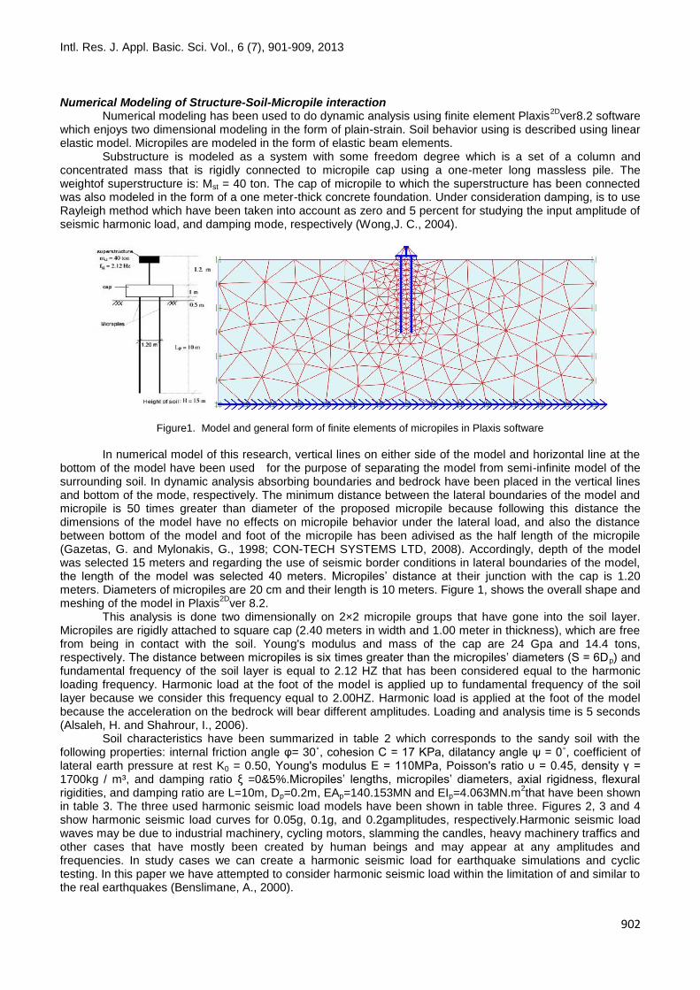
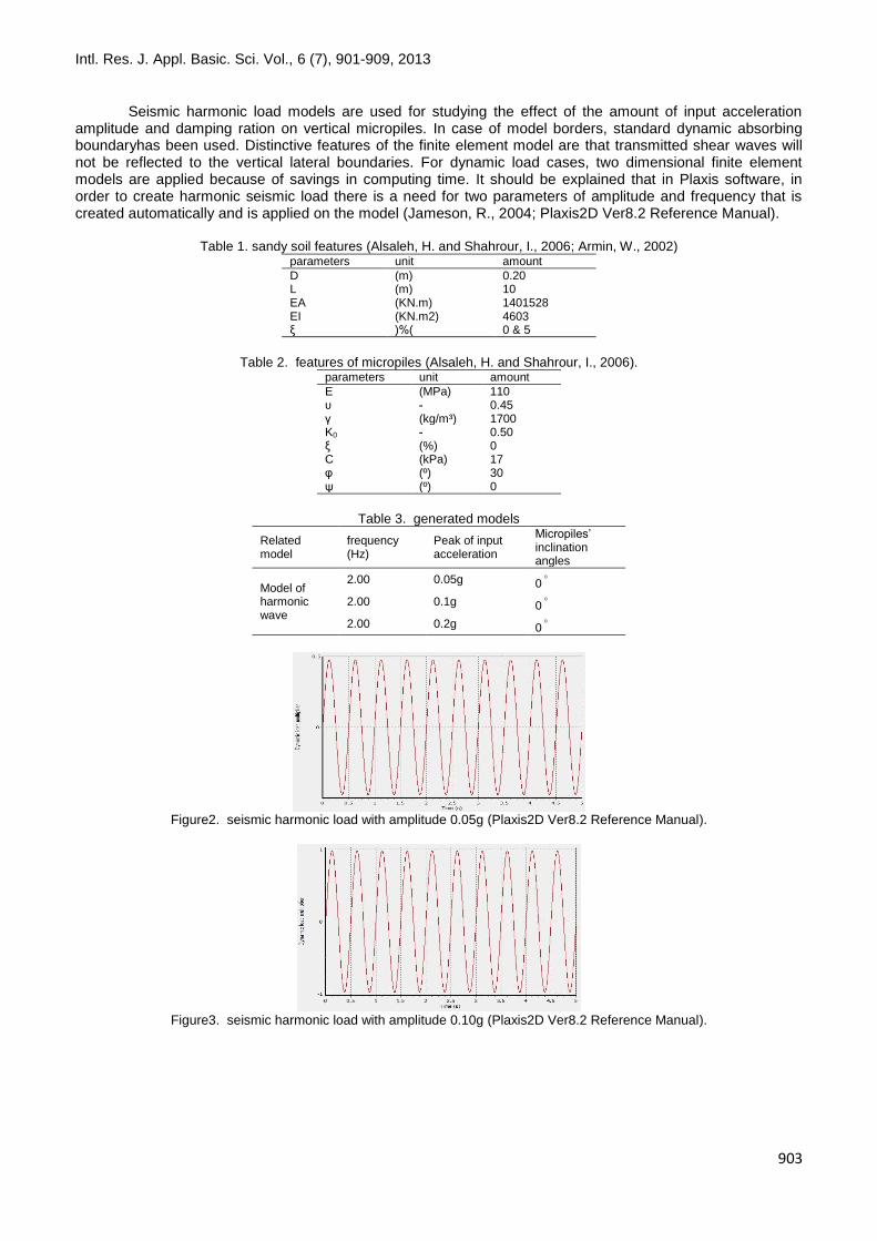
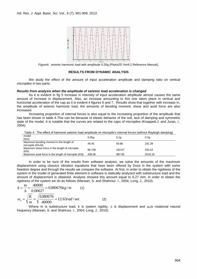
in table 3. The three used harmonic seismic load models have been shown in table three. Figures 2, 3 and 4 show harmonic seismic load curves for 0.05g, 0.1g, and 0.2gamplitudes, respectively.Harmonic seismic load waves may be due to industrial machinery, cycling motors, slamming the candles, heavy machinery traffics and other cases that have mostly been created by human beings and may appear at any amplitudes and frequencies. In study cases we can create a harmonic seismic load for earthquake simulations and cyclic testing. In this paper we have attempted to consider harmonic seismic load within the limitation of and similar to the real earthquakes (Benslimane, A., 2000).
Intl. Res. J. Appl. Basic. Sci. Vol., 6 (7), 901-909, 2013
903
Seismic harmonic load models are used for studying the effect of the amount of input acceleration amplitude and damping ration on vertical micropiles. In case of model borders, standard dynamic absorbing boundaryhas been used. Distinctive features of the finite element model are that transmitted shear waves will not be reflected to the vertical lateral boundaries. For dynamic load cases, two dimensional finite element models are applied because of savings in computing time. It should be explained that in Plaxis software, in order to create harmonic seismic load there is a need for two parameters of amplitude and frequency that is created automatically and is applied on the model (Jameson, R., 2004; Plaxis2D Ver8.2 Reference Manual).
Table 1. sandy soil features (Alsaleh, H. and Shahrour, I., 2006; Armin, W., 2002) amount unit parameters
0.20 (m) D 10 (m) L 1401528 (KN.m) EA 4603 (KN.m2) EI 0 & 5 )%( ξ
Table 2. features of micropiles (Alsaleh, H. and Shahrour, I., 2006).
amount unit parameters
110 (MPa) E 0.45 - υ 1700 (kg/m³) γ 0.50 - K0 0 (%) ξ 17 (kPa) C 30 (º) φ 0 (º) ψ
Table 3. generated models
Micropiles’ inclination angles
Peak of input acceleration
frequency (Hz)
Related model
0 0.05g 2.00 Model of harmonic wave
0 0.1g 2.00
0 0.2g 2.00
Figure2. seismic harmonic load with amplitude 0.05g (Plaxis2D Ver8.2 Reference Manual).
Figure3. seismic harmonic load with amplitude 0.10g (Plaxis2D Ver8.2 Reference Manual).
Intl. Res. J. Appl. Basic. Sci. Vol., 6 (7), 901-909, 2013
904
Figure4. seismic harmonic load with amplitude 0.20g (Plaxis2D Ver8.2 Reference Manual).
RESULTS FROM DYNAMIC ANALYSIS
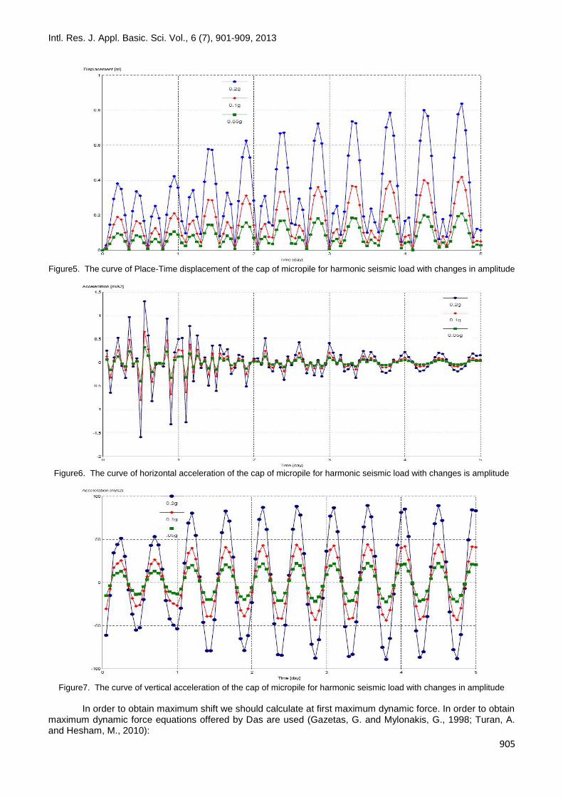
We study the effect of the amount of input acceleration amplitude and damping ratio on vertical micropiles in two parts: Results from analysis when the amplitude of seismic load acceleration is changed As it is evident in fig 5 increase in intensity of input acceleration amplitude almost causes the same amount of increase in displacement. Also, an increase amounting to this one takes place in vertical and horizontal acceleration of the cap as it is evident it figures 6 and 7. Results show that together with increase in, the amplitude of seismic harmonic load, the amounts of bending moment, shear and axial force are also increased. Increasing proportion of internal forces is also equal to the increasing proportion of the amplitude that has been shown in table 4.This can be because of elastic behavior of the soil, lack of damping and symmetric state of the model. It is notable that the curves are related to the caps of micropiles (Knappett,J. and Juran, I., 2004).
Table 4. The effect of harmonic seismic load amplitude on micropile’s internal forces (without Rayleigh damping)
0.2g 0.1g 0.05g model force
191.39 93.86 49.45 Maximum bending moment in the length of micropile (KN.M)
333.53 163.67 86.708 Maximum shear force in the length of micropile (KN)
2018.18 987.85 438.06 Maximum axial force in the length of micropile (KN)
In order to be sure of the results from software analysis, we solve the amounts of the maximum displacement using classics vibration equations that have been offered by Doss in the system with some freedom degree and through the results we compare the software. At first, in order to obtain the rigidness of the system in the model of generated finite element in software is statically analyzed with substructure load and the amount of displacement is obtained. Analysis showed this amount equal to 6.27 mm. in order to obtain the rigidness of the system we do as follows (Marwan, S. and Shahrour, I., 2004; Long, J., 2010).
mkgm
k /638067600627.0
40000
(1)
sec/63.1240000
6380676rad
m
Kn (2)
Where m is substructure load, k is system rigidity, ∆ is displacement and ωnis rotational natural frequency (Marwan, S. and Shahrour, I., 2004; Long, J., 2010).
Intl. Res. J. Appl. Basic. Sci. Vol., 6 (7), 901-909, 2013
905
Figure5. The curve of Place-Time displacement of the cap of micropile for harmonic seismic load with changes in amplitude
Figure6. The curve of horizontal acceleration of the cap of micropile for harmonic seismic load with changes is amplitude
Figure7. The curve of vertical acceleration of the cap of micropile for harmonic seismic load with changes in amplitude
In order to obtain maximum shift we should calculate at first maximum dynamic force. In order to obtain maximum dynamic force equations offered by Das are used (Gazetas, G. and Mylonakis, G., 1998; Turan, A. and Hesham, M., 2010):
Intl. Res. J. Appl. Basic. Sci. Vol., 6 (7), 901-909, 2013
906
sec/56.12214.322 radf (3)
MNQFn
dynamic 142.721763.12
56.121400001
11
0
(4)
MNFdynamic 142.725710142.721740000 3
(max)
mK
FZ
dynamic
mandynamic 137.1676.6380
142.7257(max)
)( (5)
Where is frequency, f is load frequency, (max)dynamicF is maximum is dynamic force, and
(max)dynamicZ is maximum displacement. All of the obtained cases from analysis in models are less than the
above mentioned (maximum) amount and this shows the correctness of the obtained results. Results from analysis with stable acceleration amplitude of seismic load Geometric dimensions of this model is similar to the previous model so that soil behavior is described using the Mohr-coulombin elasto-plastic state. Harmonic loading frequency has been considered equal to 2.00 HZ. For this reason harmonic loading is applied for 5 seconds at the foot of the model and the acceleration of bedrock will have 0.2g amplitude. Rayleigh damping ratio has been used in the two states for materials, being capable of damping and without damping, and in this way the effect of damping ratio will be studied. For the
state of being capable of dampingratio %=5ξ has been used for soil. Parameters , from the below
equations that have been offered by the organization of highways of America, are determined and entered into specifications of materials (FHWA, 2000; A.M.ASCE2).
minminminmin /, (6,7)
ss HV 4/min (8)
0667.1)154/(64min
04687.00667.1
05.0
0533.00667.105.0
In order to control the results of these formulas, given damping ration, we can obtain two angle frequencies in two main modes. Considering the damping ratio of 5% we have (Sivakumar, G., 2009):
i
i
i
2
1 (9)
iii 22 (10)
28.1,23.1 21
And using the equations 9 and 10 we have [5]:
05.023.1223.1 2 i
05.028.1228.1 2 i
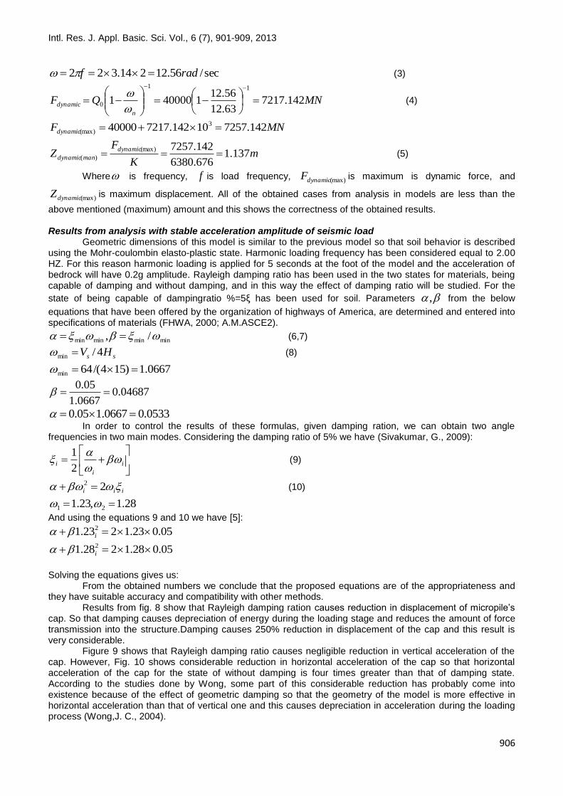
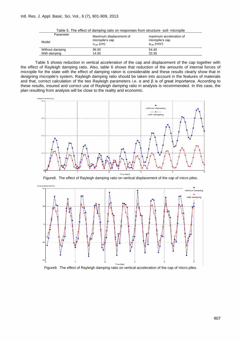
Solving the equations gives us: From the obtained numbers we conclude that the proposed equations are of the appropriateness and they have suitable accuracy and compatibility with other methods. Results from fig. 8 show that Rayleigh damping ration causes reduction in displacement of micropile’s cap. So that damping causes depreciation of energy during the loading stage and reduces the amount of force transmission into the structure.Damping causes 250% reduction in displacement of the cap and this result is very considerable. Figure 9 shows that Rayleigh damping ratio causes negligible reduction in vertical acceleration of the cap. However, Fig. 10 shows considerable reduction in horizontal acceleration of the cap so that horizontal acceleration of the cap for the state of without damping is four times greater than that of damping state. According to the studies done by Wong, some part of this considerable reduction has probably come into existence because of the effect of geometric damping so that the geometry of the model is more effective in horizontal acceleration than that of vertical one and this causes depreciation in acceleration during the loading process (Wong,J. C., 2004).
Intl. Res. J. Appl. Basic. Sci. Vol., 6 (7), 901-909, 2013
907
Table 5. The effect of damping ratio on responses from structure- soil- micropile
maximum acceleration of micropile’s cap acap (m/s²)
Maximum displacement of micropile’s cap ∆cap (cm)
Parameter Model
54.40 36.00 Without damping 33.35 14.00 With damping
Table 5 shows reduction in vertical acceleration of the cap and displacement of the cap together with the effect of Rayleigh damping ratio. Also, table 6 shows that reduction of the amounts of internal forces of micropile for the state with the effect of damping ration is considerable and these results clearly show that in designing micropile's system, Rayleigh damping ratio should be taken into account in the features of materials and that, correct calculation of the two Rayleigh parameters i.e. α and β is of great importance. According to these results, insured and correct use of Rayleigh damping ratio in analysis is recommended. In this case, the plan resulting from analysis will be close to the reality and economic.
Figure8. The effect of Rayleigh damping ratio on vertical displacement of the cap of micro piles.
Figure9. The effect of Rayleigh damping ratio on vertical acceleration of the cap of micro piles.
Intl. Res. J. Appl. Basic. Sci. Vol., 6 (7), 901-909, 2013
908
Figure10. The effect of Rayleigh damping ratio on horizontal acceleration of the cap of micropiles
Table 6. The effect of damping on internal forces of micropiles
With damping Without damping
model force
37.04 87.52 Maximum bending moment in the length of micropile (KN.M)
63.29 141.23 Maximum shear force in the length of micropile (KN)
1762.44 857.31 Maximum axial force in the length of micropile (KN)
One of the most important issues in using the explicit methods for solving dynamic problems is stability and convergence of the solution. Growth for stable time when damping is negligible:
max
2
t
Growth for stable time when damping should be entered into calculations (Gazetas, G. and Mylonakis, G., 1998):
min
2
max
max
12
t
Critical damping ratio in mode is with the greatest frequency. A close look at the second phrase makes it clear that entering the damping in the two above phrases solely in calculations causes the growth of stable time to be reduced.
CONCLUSION Results from dynamic analysis of the models are as follows: Increase in the amplitude of input acceleration, almost with the same increase amount, also causes increase in displacement and acceleration. This takes place because the model is symmetric. Increase in amplitude of seismic harmonic load causes increase in the amounts of bending moment, shear force and axial force. The ratio of increase in internal forces is almost equal to the ratio of increase in amplitude. The ratio of Rayleigh damping, caused depreciation in seismic load energy in harmonic state and consequently causes reduction in the amounts of internal forces of micropile and also the cap of micropiles. The ratio of Rayleigh damping causes reduction in displacement of microplie’s cap. Damping causes 250% reduction in the cap’s displacement and this result is very considerable. The ratio of Rayleighdamping causes negligible reduction in vertical acceleration of the cap of micropile. However, results show considerable reduction in horizontal acceleration of the cap so that horizontal acceleration of the cap for the state of without damping is four times greater than that of the damping state. Using the model with the effect of the ratio of Rayleigh damping is closer to the reality. Therefore, correctly selecting and applying the ratio of damping in analysis is recommended.
Intl. Res. J. Appl. Basic. Sci. Vol., 6 (7), 901-909, 2013
909
REFERENCES A.M.ASCE2.”Reliability-Based Design and Construction Issues for a Micropile Foundation in Costa Rica”.FulvioTonon, A.M.ASCE1 and
Armando Mammino, A.M.ASCE2. Alsaleh H, Shahrour I. 2006. “Three–dimensional nonlinear finite difference analysis for seismic soil micropile. Structure interaction- effects
of nonlinearity of soil and micropile-soil interface”.4th International Flac Symposium on Numerical in Geomechanics, Armin W.2002.“Tension and compression micropile load tests in gravelly sand”. Horvitz. Hart Crower, Inc. Seattle, Washington, USA, Atermoghadam F. 2012. “Parametric investigation of seismic behavior of Micropiles groups”, M.S. Thesis, University ofTafresh, Markazi,
Iran, Benslimane A.2000.“Dynamic behavior of micropile systems Subjected to Sinusoidal Ground Motions ,Centrifugal Model Studies”, Thesis
submitted in partial fulfillment of requirements for the degree of Doctor of philosophy at The Polytechnic University, CON-TECH SYSTEMS LTD. 2008. “Micropile reinforcement systems and corrosion protection”.Horst Aschenbroich, Dipl. Ing.President and
CEO, Delta BC, Canada. Federal Highway Administration. 2005. “Seismic Behavior of Micropiles”, Report No. FHWA WA-RD-6041, United States Department of
Transportation, FHWA. 2000.”Micropile design and construction guidelines”, US Department of Transportation, Federal Highway Administration, Priority
Technologies Program, Implementational, manual, Publication No. FHWA - SA-97-070. Gazetas G, Mylonakis G. 1998. “Seismic soil-structure interaction: New evidence and emerging issues”. ASCE Special Edition No.75
Geotechnical Earthquake Engineering and Soil Dynamic. Jameson R.2004.CA, USA “Evolving micro-piles: optimizing foundations for seismic retrofit”, Malcolm Drilling Company, Hayward, CA, USA
and Leo Panian, Tipping Mar & Associates, Berkeley, CA, USA and Bill Rudolph, Engeo, San Ramon, CA, USA, Knappett J, Juran I. 2004. “Seismic behavior of micropile systems” Ground Improvement, 8, No. 3, 109–120, Bolton Department of
Engineering, University of Cambridge, Long J.2010.“Results of lateral load tests on micropiles” Member, Geo-Institute, Massimo Maniaci, Glen Menezes, Rory Ball, Marwan S, Shahrour I. 2004. “Three-dimensional finite element analysis of the seismic behavior of inclined micropiles”. Laboratories
deMe´canique de Lille (CNRS UMR 8107), Universities´ des Sciences et Technologies de Lille (USTL), Po¨lytech-Lille, 59 655 Villeneuve d’AscqCedex, France,
Plaxis2D
Ver8.2 Reference Manual. Plaxis by P.O. Box 5722600 AN Delft the Netherlands. [email protected] or www.Plaxis.nl. Sivakumar G. 2009. “Bearingcapacityimprovementusingmicropilesacasestudy”, B. R.Srinivasa Murthy, D.S. N. Murthy, M.S. Nataraj, Turan A, Hesham M. 2010. “Lateral behavior of micro-pile groups under static and dynamic loads”.Department of Civil and Environmental
Engineering, The University of Western Ontario, London, ON, Canada, Wong JC.2004.“Seismic behavior of micropiles”, M.S. Thesis Washington State University, Pullman,WA, USA,