Embed Size (px)
Citation preview

Parameters of 3D sensing techniques in a nutshell
Tomas Kovacovsky (CTO, Photoneo)
Machine Vision is one of the driving forces of industrial automation. For a long time, it’s been primarily pushed forward by improvements made in 2D image sensing, and for some applications, 2D sensing is still an optimal tool to solve a problem. But the majority of challenges machine vision is facing today has a 3D character. From a well-established metrology up to new applications in smart robotics, 3D sensors serve as a main source of data. Under a 3D sensor, we understand a sensor that is able to capture 3D features of inspected surface. While we are talking about the machine vision, we will not consider non-optical systems in this category. Nowadays, market offers a wide variety of 3D sensoric solutions, most of them claiming a superiority over their competition. While a lot of these claims are based on a rational reasoning, one needs to understand differences and the need for individual applications. For QR code reading, a 2D smart camera can be the best solution on market. But it will probably not guide a logistic robot from one facility to another. In this field, it can’t compete with LIDAR based solutions currently dominating that market. Not considering interferometry and a nm range, we can list typical, most common technologies currently used in the industry:
● Laser triangulation (or profilometry) ● Photogrammetry ● Stereo vision (passive and active) ● Structured light (one frame, multiple frames) ● Time-of-flight (area scan or LIDAR)
A more detailed description with the primary use cases and categorization based on our chosen parameters can be found at the end of the paper. It is important to realize it is impossible to create an optimal solution that satisfies all needs. Let’s concentrate on the most important parameters and reasons why they can not be easily extended, or what are the trade-offs of having some parameter pretty high. We will define 5
levels in each category that will help us compare individual technologies and possibilities they provide.
Parameters
Operating volume
A typical operating volume of a system used for metrology application is about 100mm x 100mm x 20mm, while typical need of a bin picking solution is about 1 m3. This looks just as a simple change in parameters, but in reality, with different operating volumes, different technologies excel.
While increasing the range in the XY directions is more related to FOV of the system and can be extended by using wider lens, the extension in Z directions brings the problem of keeping the object into focus. This is called a depth of field. Deeper the depth of field needs to be, the smaller the aperture of the camera (or projector) has to be. This strongly limits the number of photons reaching the sensor and as a result limits the usage of some technologies in a higher depth range. We can define five categories based on its depth of field range:
1. Very small: up to 50 mm 2. Small: up to 500 mm 3. Medium: up to 1500 mm 4. Large: up to 4 m 5. Very large: up to 100 m
While extending the depth range of the camera is executed by shrinking the aperture, it will limit the amount of captured light (both from your light source, in active system, and of an ambient illumination). A more complex problem is to extend the depth range of the active projection system, where shrinking down the aperture will limit only signal without limiting the ambient illumination. Here, laser based projection systems (as used in Photoneo’s 3D sensors) excel, with their ability to achieve almost unlimited depth of field..
Data acquisition and processing time
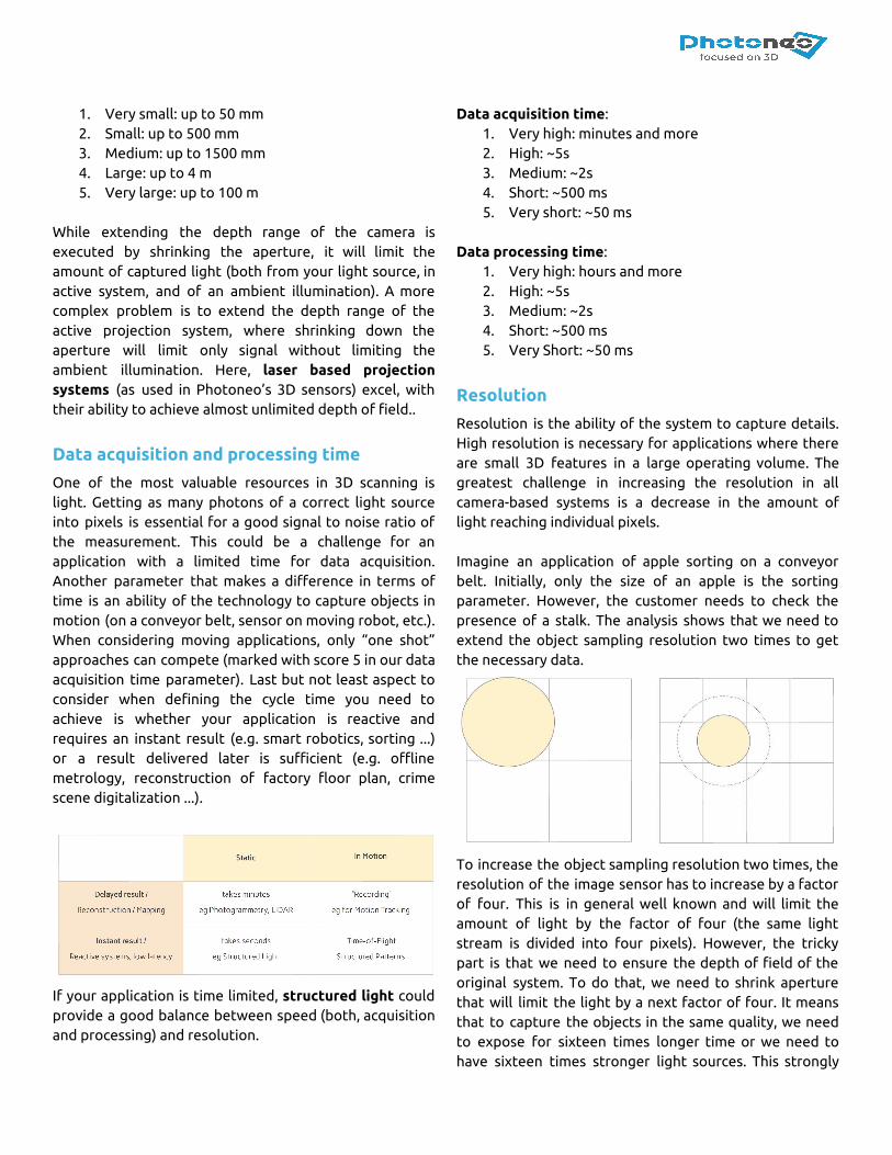
One of the most valuable resources in 3D scanning is light. Getting as many photons of a correct light source into pixels is essential for a good signal to noise ratio of the measurement. This could be a challenge for an application with a limited time for data acquisition. Another parameter that makes a difference in terms of time is an ability of the technology to capture objects in motion (on a conveyor belt, sensor on moving robot, etc.). When considering moving applications, only “one shot” approaches can compete (marked with score 5 in our data acquisition time parameter). Last but not least aspect to consider when defining the cycle time you need to achieve is whether your application is reactive and requires an instant result (e.g. smart robotics, sorting ...) or a result delivered later is sufficient (e.g. offline metrology, reconstruction of factory floor plan, crime scene digitalization ...).
If your application is time limited, structured light could provide a good balance between speed (both, acquisition and processing) and resolution.
Data acquisition time: 1. Very high: minutes and more 2. High: ~5s 3. Medium: ~2s 4. Short: ~500 ms 5. Very short: ~50 ms
Data processing time:
1. Very high: hours and more 2. High: ~5s 3. Medium: ~2s 4. Short: ~500 ms 5. Very Short: ~50 ms
Resolution
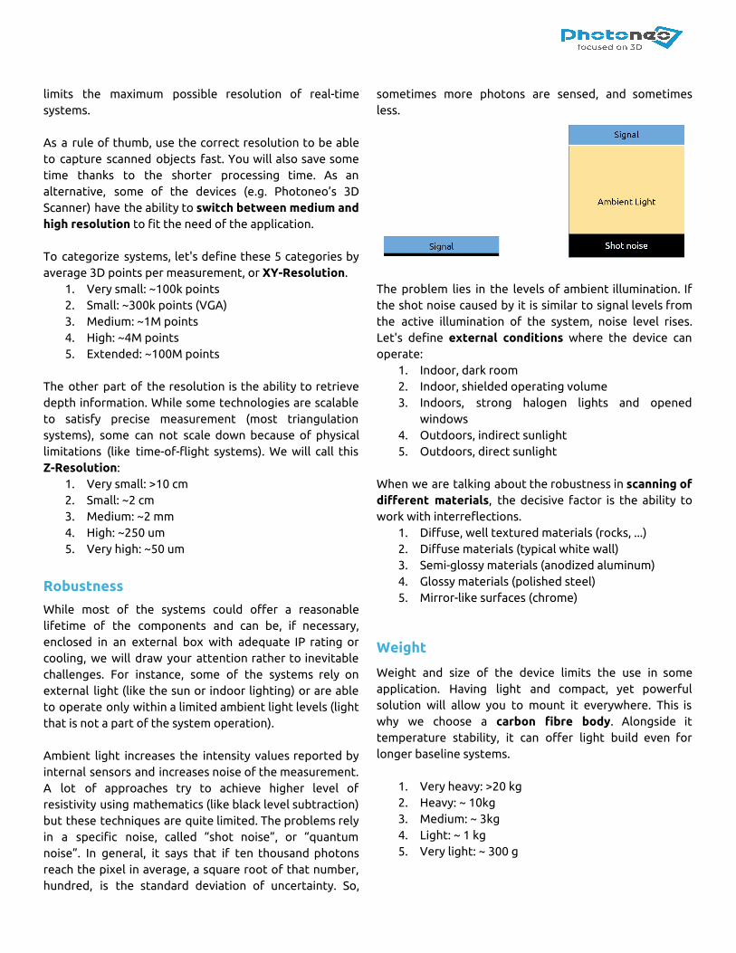
Resolution is the ability of the system to capture details. High resolution is necessary for applications where there are small 3D features in a large operating volume. The greatest challenge in increasing the resolution in all camera-based systems is a decrease in the amount of light reaching individual pixels. Imagine an application of apple sorting on a conveyor belt. Initially, only the size of an apple is the sorting parameter. However, the customer needs to check the presence of a stalk. The analysis shows that we need to extend the object sampling resolution two times to get the necessary data.
To increase the object sampling resolution two times, the resolution of the image sensor has to increase by a factor of four. This is in general well known and will limit the amount of light by the factor of four (the same light stream is divided into four pixels). However, the tricky part is that we need to ensure the depth of field of the original system. To do that, we need to shrink aperture that will limit the light by a next factor of four. It means that to capture the objects in the same quality, we need to expose for sixteen times longer time or we need to have sixteen times stronger light sources. This strongly
limits the maximum possible resolution of real-time systems. As a rule of thumb, use the correct resolution to be able to capture scanned objects fast. You will also save some time thanks to the shorter processing time. As an alternative, some of the devices (e.g. Photoneo’s 3D Scanner) have the ability to switch between medium and high resolution to fit the need of the application. To categorize systems, let's define these 5 categories by average 3D points per measurement, or XY-Resolution.
1. Very small: ~100k points 2. Small: ~300k points (VGA) 3. Medium: ~1M points 4. High: ~4M points 5. Extended: ~100M points
The other part of the resolution is the ability to retrieve depth information. While some technologies are scalable to satisfy precise measurement (most triangulation systems), some can not scale down because of physical limitations (like time-of-flight systems). We will call this Z-Resolution:
1. Very small: >10 cm 2. Small: ~2 cm 3. Medium: ~2 mm 4. High: ~250 um 5. Very high: ~50 um
Robustness
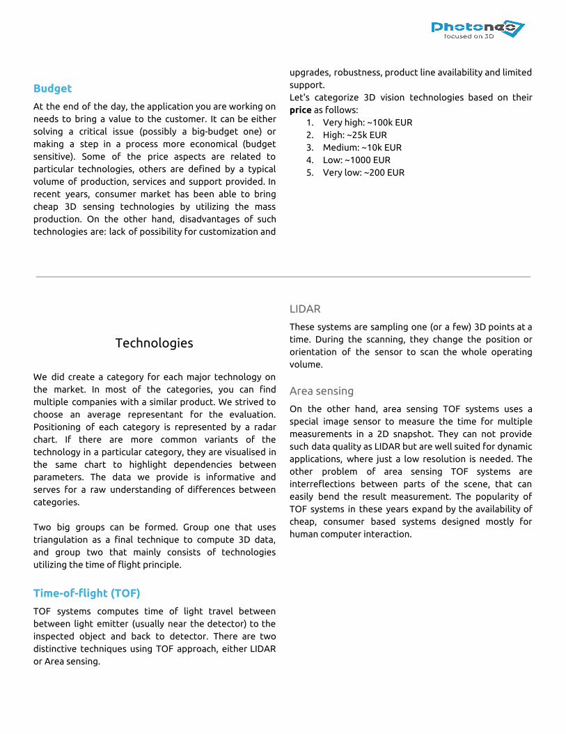
While most of the systems could offer a reasonable lifetime of the components and can be, if necessary, enclosed in an external box with adequate IP rating or cooling, we will draw your attention rather to inevitable challenges. For instance, some of the systems rely on external light (like the sun or indoor lighting) or are able to operate only within a limited ambient light levels (light that is not a part of the system operation). Ambient light increases the intensity values reported by internal sensors and increases noise of the measurement. A lot of approaches try to achieve higher level of resistivity using mathematics (like black level subtraction) but these techniques are quite limited. The problems rely in a specific noise, called “shot noise”, or “quantum noise”. In general, it says that if ten thousand photons reach the pixel in average, a square root of that number, hundred, is the standard deviation of uncertainty. So,
sometimes more photons are sensed, and sometimes less.
The problem lies in the levels of ambient illumination. If the shot noise caused by it is similar to signal levels from the active illumination of the system, noise level rises. Let's define external conditions where the device can operate:
1. Indoor, dark room 2. Indoor, shielded operating volume 3. Indoors, strong halogen lights and opened
windows 4. Outdoors, indirect sunlight 5. Outdoors, direct sunlight
When we are talking about the robustness in scanning of different materials, the decisive factor is the ability to work with interreflections.
1. Diffuse, well textured materials (rocks, ...) 2. Diffuse materials (typical white wall) 3. Semi-glossy materials (anodized aluminum) 4. Glossy materials (polished steel) 5. Mirror-like surfaces (chrome)
Weight
Weight and size of the device limits the use in some application. Having light and compact, yet powerful solution will allow you to mount it everywhere. This is why we choose a carbon fibre body. Alongside it temperature stability, it can offer light build even for longer baseline systems.
1. Very heavy: >20 kg 2. Heavy: ~ 10kg 3. Medium: ~ 3kg 4. Light: ~ 1 kg 5. Very light: ~ 300 g
Budget
At the end of the day, the application you are working on needs to bring a value to the customer. It can be either solving a critical issue (possibly a big-budget one) or making a step in a process more economical (budget sensitive). Some of the price aspects are related to particular technologies, others are defined by a typical volume of production, services and support provided. In recent years, consumer market has been able to bring cheap 3D sensing technologies by utilizing the mass production. On the other hand, disadvantages of such technologies are: lack of possibility for customization and
upgrades, robustness, product line availability and limited support. Let's categorize 3D vision technologies based on their price as follows:
1. Very high: ~100k EUR 2. High: ~25k EUR 3. Medium: ~10k EUR 4. Low: ~1000 EUR 5. Very low: ~200 EUR
Technologies
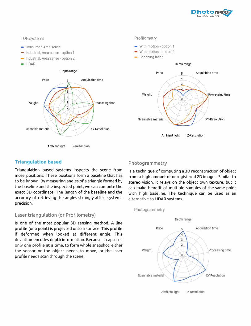
We did create a category for each major technology on the market. In most of the categories, you can find multiple companies with a similar product. We strived to choose an average representant for the evaluation. Positioning of each category is represented by a radar chart. If there are more common variants of the technology in a particular category, they are visualised in the same chart to highlight dependencies between parameters. The data we provide is informative and serves for a raw understanding of differences between categories. Two big groups can be formed. Group one that uses triangulation as a final technique to compute 3D data, and group two that mainly consists of technologies utilizing the time of flight principle.
Time-of-flight (TOF)
TOF systems computes time of light travel between between light emitter (usually near the detector) to the inspected object and back to detector. There are two distinctive techniques using TOF approach, either LIDAR or Area sensing.
LIDAR
These systems are sampling one (or a few) 3D points at a time. During the scanning, they change the position or orientation of the sensor to scan the whole operating volume.
Area sensing
On the other hand, area sensing TOF systems uses a special image sensor to measure the time for multiple measurements in a 2D snapshot. They can not provide such data quality as LIDAR but are well suited for dynamic applications, where just a low resolution is needed. The other problem of area sensing TOF systems are interreflections between parts of the scene, that can easily bend the result measurement. The popularity of TOF systems in these years expand by the availability of cheap, consumer based systems designed mostly for human computer interaction.
Triangulation based
Triangulation based systems inspects the scene from more positions. These positions form a baseline that has to be known. By measuring angles of a triangle formed by the baseline and the inspected point, we can compute the exact 3D coordinate. The length of the baseline and the accuracy of retrieving the angles strongly affect systems precision.
Laser triangulation (or Profilometry)
Is one of the most popular 3D sensing method. A line profile (or a point) is projected onto a surface. This profile if deformed when looked at different angle. This deviation encodes depth information. Because it captures only one profile at a time, to form whole snapshot, either the sensor or the object needs to move, or the laser profile needs scan through the scene.
Photogrammetry
Is a technique of computing a 3D reconstruction of object from a high amount of unregistered 2D images. Similar to stereo vision, it relays on the object own texture, but it can make benefit of multiple samples of the same point with high baseline. The technique can be used as an alternative to LIDAR systems.
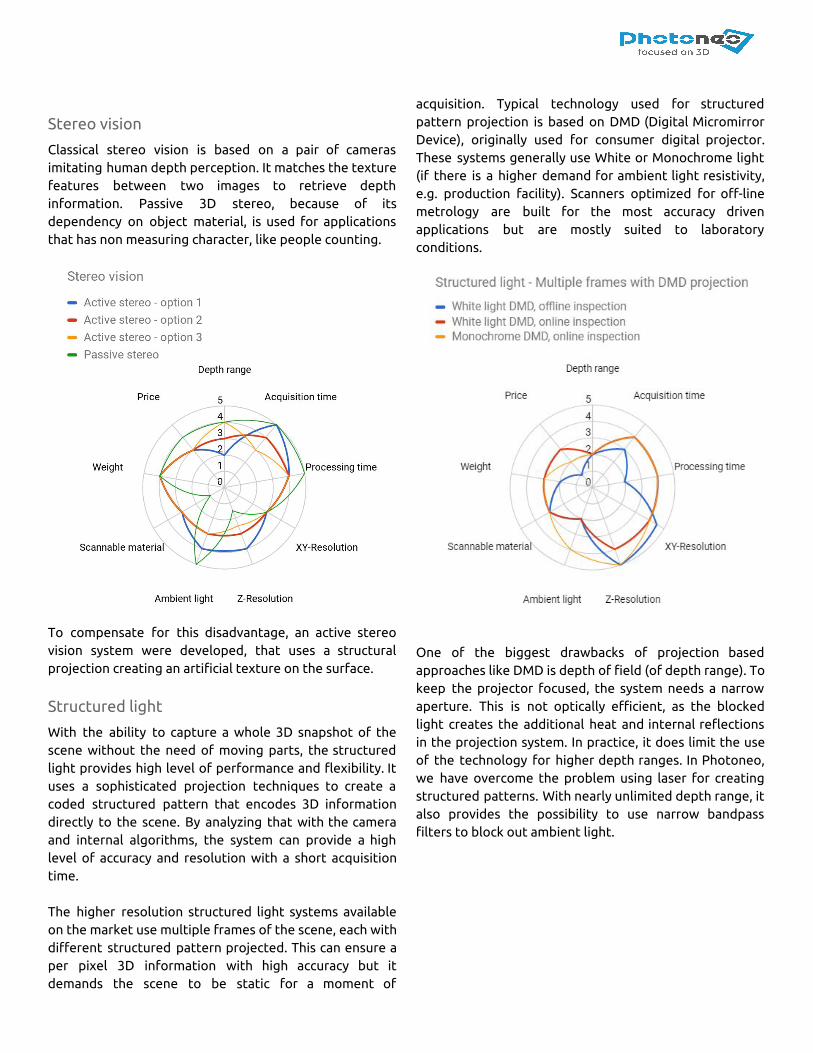
Stereo vision
Classical stereo vision is based on a pair of cameras imitating human depth perception. It matches the texture features between two images to retrieve depth information. Passive 3D stereo, because of its dependency on object material, is used for applications that has non measuring character, like people counting.
To compensate for this disadvantage, an active stereo vision system were developed, that uses a structural projection creating an artificial texture on the surface.
Structured light
With the ability to capture a whole 3D snapshot of the scene without the need of moving parts, the structured light provides high level of performance and flexibility. It uses a sophisticated projection techniques to create a coded structured pattern that encodes 3D information directly to the scene. By analyzing that with the camera and internal algorithms, the system can provide a high level of accuracy and resolution with a short acquisition time. The higher resolution structured light systems available on the market use multiple frames of the scene, each with different structured pattern projected. This can ensure a per pixel 3D information with high accuracy but it demands the scene to be static for a moment of
acquisition. Typical technology used for structured pattern projection is based on DMD (Digital Micromirror Device), originally used for consumer digital projector. These systems generally use White or Monochrome light (if there is a higher demand for ambient light resistivity, e.g. production facility). Scanners optimized for off-line metrology are built for the most accuracy driven applications but are mostly suited to laboratory conditions.
One of the biggest drawbacks of projection based approaches like DMD is depth of field (of depth range). To keep the projector focused, the system needs a narrow aperture. This is not optically efficient, as the blocked light creates the additional heat and internal reflections in the projection system. In practice, it does limit the use of the technology for higher depth ranges. In Photoneo, we have overcome the problem using laser for creating structured patterns. With nearly unlimited depth range, it also provides the possibility to use narrow bandpass filters to block out ambient light.
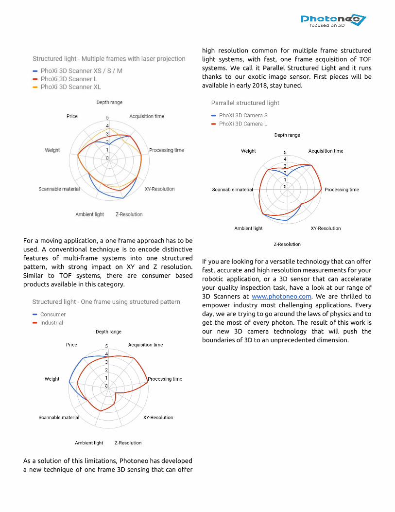
For a moving application, a one frame approach has to be used. A conventional technique is to encode distinctive features of multi-frame systems into one structured pattern, with strong impact on XY and Z resolution. Similar to TOF systems, there are consumer based products available in this category.
As a solution of this limitations, Photoneo has developed a new technique of one frame 3D sensing that can offer
high resolution common for multiple frame structured light systems, with fast, one frame acquisition of TOF systems. We call it Parallel Structured Light and it runs thanks to our exotic image sensor. First pieces will be available in early 2018, stay tuned.
If you are looking for a versatile technology that can offer fast, accurate and high resolution measurements for your robotic application, or a 3D sensor that can accelerate your quality inspection task, have a look at our range of 3D Scanners at www.photoneo.com. We are thrilled to empower industry most challenging applications. Every day, we are trying to go around the laws of physics and to get the most of every photon. The result of this work is our new 3D camera technology that will push the boundaries of 3D to an unprecedented dimension.