Embed Size (px)
DESCRIPTION
Tutorial ANSYS
Citation preview
Customer Training Material
L t 6Lecture 6
CAD Connections and Parameterization
Introduction to ANSYSIntroduction to ANSYSDesignModeler
L6-1ANSYS, Inc. Proprietary© 2010 ANSYS, Inc. All rights reserved.
Release 13.0December 2010
Introduction to ANSYS DesignModeler
Customer Training MaterialCAD Connections and ParameterizationWhat will you learn from this presentation:
CAD Connections
Bi-Directional Connectivity
Named Selection Manager
ParameterizationParameters through bi-directional CAD association
Parameters within DM
Combination of above two
Appendix
L6-2ANSYS, Inc. Proprietary© 2010 ANSYS, Inc. All rights reserved.
Release 13.0December 2010
Introduction to ANSYS DesignModeler
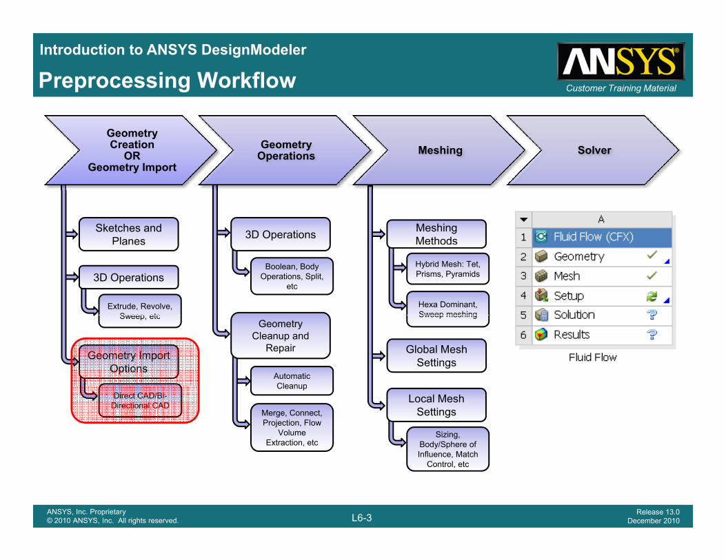
Customer Training MaterialPreprocessing Workflow
Geometry Creation
OR Geometry Import
Geometry Operations Meshing Solver
Sketches and Planes 3D Operations Meshing
Methodsa es
3D Operations
Extrude, Revolve, Sweep etc
Boolean, Body Operations, Split,
etc
Hybrid Mesh: Tet, Prisms, Pyramids
Hexa Dominant, Sweep meshing
Geometry Import Options
Geometry Cleanup and
Repair
Automatic Cleanup
Sweep, etc Sweep meshing
Global Mesh Settings
Direct CAD/Bi-Directional CAD
Cleanup
Merge, Connect, Projection, Flow
Volume Extraction, etc
Local Mesh Settings
Sizing, Body/Sphere of Influence, Match
L6-3ANSYS, Inc. Proprietary© 2010 ANSYS, Inc. All rights reserved.
Release 13.0December 2010
Influence, Match Control, etc
Introduction to ANSYS DesignModeler
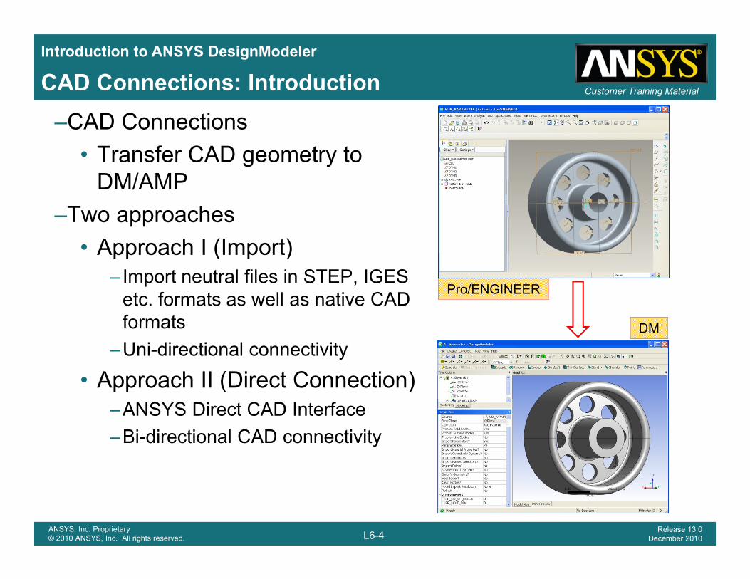
Customer Training MaterialCAD Connections: Introduction–CAD Connections
• Transfer CAD geometry to DM/AMPDM/AMP
–Two approaches• Approach I (Import)Approach I (Import)
–Import neutral files in STEP, IGES etc. formats as well as native CAD formats
Pro/ENGINEER
DMformats–Uni-directional connectivity
• Approach II (Direct Connection)
DM
–ANSYS Direct CAD Interface–Bi-directional CAD connectivity
L6-4ANSYS, Inc. Proprietary© 2010 ANSYS, Inc. All rights reserved.
Release 13.0December 2010
Introduction to ANSYS DesignModeler
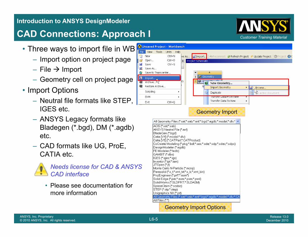
Customer Training MaterialCAD Connections: Approach I• Three ways to import file in WB
– Import option on project page– File Import– Geometry cell on project page
• Import Options– Neutral file formats like STEP, ,
IGES etc.– ANSYS Legacy formats like
Bladegen (*.bgd), DM (*.agdb) t
Geometry Import
etc.– CAD formats like UG, ProE,
CATIA etc.
Needs license for CAD & ANSYS CAD interface
• Please see documentation for more information
L6-5ANSYS, Inc. Proprietary© 2010 ANSYS, Inc. All rights reserved.
Release 13.0December 2010
more information
Geometry Import Options
Introduction to ANSYS DesignModeler
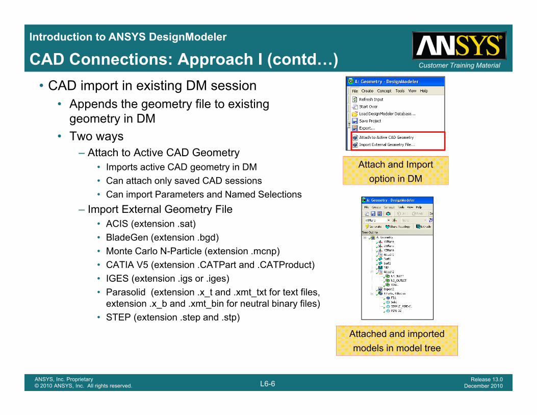
Customer Training MaterialCAD Connections: Approach I (contd…)• CAD import in existing DM session
• Appends the geometry file to existing geometry in DM
• Two ways– Attach to Active CAD Geometry
• Imports active CAD geometry in DM• Can attach only saved CAD sessions
Attach and Import option in DM• Can attach only saved CAD sessions
• Can import Parameters and Named Selections– Import External Geometry File
• ACIS (extension .sat) Bl d G ( i b d)
option in DM
• BladeGen (extension .bgd) • Monte Carlo N-Particle (extension .mcnp) • CATIA V5 (extension .CATPart and .CATProduct) • IGES (extension .igs or .iges) • Parasolid (extension .x_t and .xmt_txt for text files,
extension .x_b and .xmt_bin for neutral binary files)• STEP (extension .step and .stp)
Attached and imported
L6-6ANSYS, Inc. Proprietary© 2010 ANSYS, Inc. All rights reserved.
Release 13.0December 2010
pmodels in model tree
Introduction to ANSYS DesignModeler
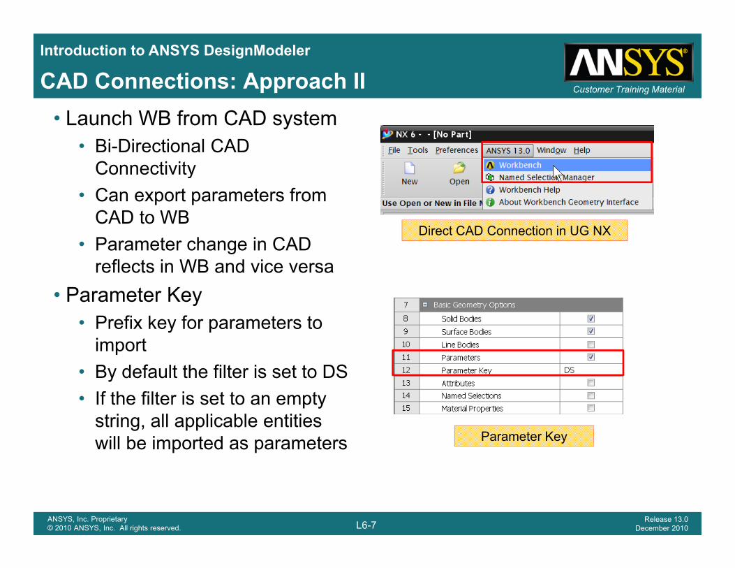
Customer Training MaterialCAD Connections: Approach II• Launch WB from CAD system
• Bi-Directional CAD Connectivityy
• Can export parameters from CAD to WB
• Parameter change in CADDirect CAD Connection in UG NX
Parameter change in CAD reflects in WB and vice versa
• Parameter KeyPrefix key for parameters to• Prefix key for parameters to import
• By default the filter is set to DSIf h fil i• If the filter is set to an empty string, all applicable entities will be imported as parameters Parameter Key
L6-7ANSYS, Inc. Proprietary© 2010 ANSYS, Inc. All rights reserved.
Release 13.0December 2010
Introduction to ANSYS DesignModeler
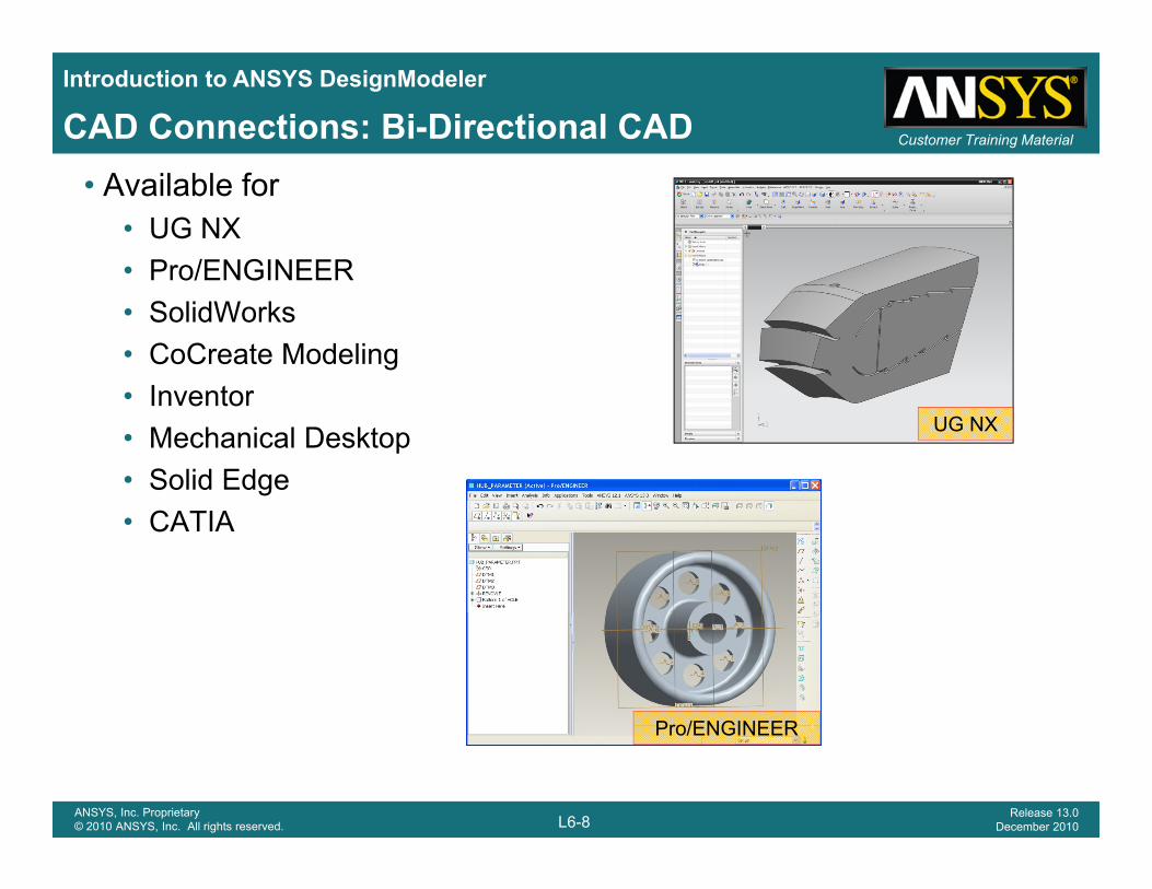
Customer Training MaterialCAD Connections: Bi-Directional CAD• Available for
• UG NX• Pro/ENGINEERPro/ENGINEER• SolidWorks• CoCreate Modeling
I t• Inventor• Mechanical Desktop• Solid Edge
UG NX
• CATIA
Pro/ENGINEER
L6-8ANSYS, Inc. Proprietary© 2010 ANSYS, Inc. All rights reserved.
Release 13.0December 2010
Pro/ENGINEER
Introduction to ANSYS DesignModeler
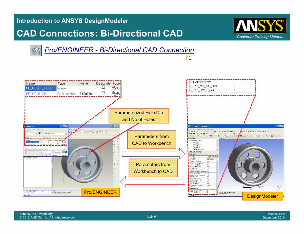
Customer Training MaterialCAD Connections: Bi-Directional CADPro/ENGINEER - Bi-Directional CAD Connection
Parameterized Hole Dia and No of Holes
Parameters from CAD to Workbench
P /ENGINEER
Parameters from Workbench to CAD
L6-9ANSYS, Inc. Proprietary© 2010 ANSYS, Inc. All rights reserved.
Release 13.0December 2010
Pro/ENGINEERDesignModeler
h1
Slide 9
h1 Please change fisrst slide for demo,Mention it as demo"Say Click here to start demo"hsahire, 11/26/2010
Introduction to ANSYS DesignModeler
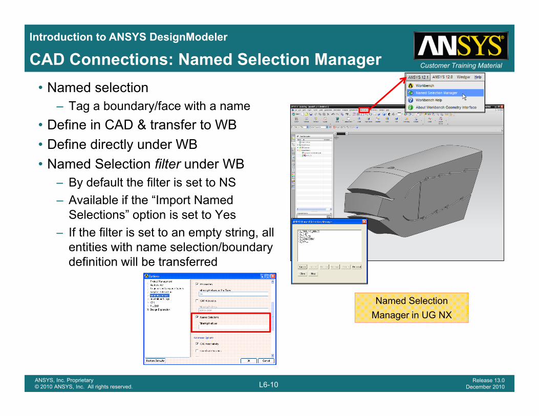
Customer Training MaterialCAD Connections: Named Selection Manager• Named selection
– Tag a boundary/face with a name• Define in CAD & transfer to WBe e C & a s e o• Define directly under WB• Named Selection filter under WB
By default the filter is set to NS– By default the filter is set to NS– Available if the “Import Named
Selections” option is set to Yes– If the filter is set to an empty string allIf the filter is set to an empty string, all
entities with name selection/boundary definition will be transferred
Named Selection Manager in UG NX
L6-10ANSYS, Inc. Proprietary© 2010 ANSYS, Inc. All rights reserved.
Release 13.0December 2010
Introduction to ANSYS DesignModeler
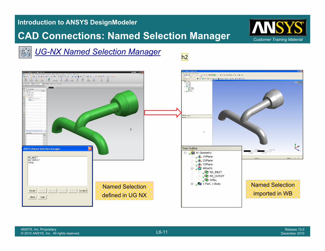
Customer Training MaterialCAD Connections: Named Selection ManagerUG-NX Named Selection Manager
Named Selection defined in UG NX
Named Selection imported in WB
L6-11ANSYS, Inc. Proprietary© 2010 ANSYS, Inc. All rights reserved.
Release 13.0December 2010
h2
Slide 11
h2 Chnge the demo starting slideCheck the slide headingshsahire, 11/26/2010
Introduction to ANSYS DesignModeler
Customer Training MaterialParameterization
What is Parameterization?• Parameterization helps to execute a set of operations repeatedly with
different set of values– Important features, such as diameter of cooling holes, camber etc can be
made parametricp
– Very useful for analyzing various design points by modifying geometry/topology parameters
• DM supports sketch to 3D approach to create parametric models in• DM supports sketch-to-3D approach to create parametric models in addition to accessing direct CAD parameters
– Plane creation inputs, Sketch dimensions, 3D operation limiting values , etc can be treated as parameters
– The parameters can be linked with each other through expressions
L6-12ANSYS, Inc. Proprietary© 2010 ANSYS, Inc. All rights reserved.
Release 13.0December 2010
Introduction to ANSYS DesignModeler
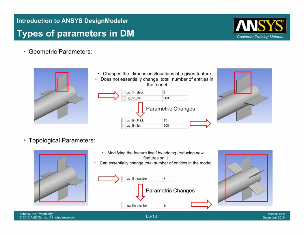
Customer Training MaterialTypes of parameters in DM
• Geometric Parameters:
Changes the dimensions/locations of a gi en feat re• Changes the dimensions/locations of a given feature• Does not essentially change total number of entities in
the model
Parametric Changes
• Topological Parameters:
• Modifying the feature itself by adding /reducing new features on it
C f
Parametric Changes
• Can essentially change total number of entities in the model
L6-13ANSYS, Inc. Proprietary© 2010 ANSYS, Inc. All rights reserved.
Release 13.0December 2010
Parametric Changes
Introduction to ANSYS DesignModeler
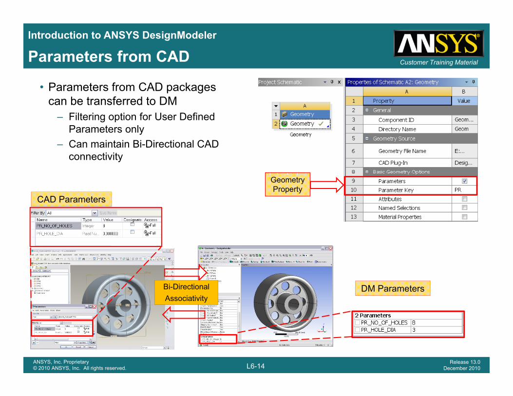
Customer Training MaterialParameters from CAD
• Parameters from CAD packages can be transferred to DM
– Filtering option for User Defined Parameters only
– Can maintain Bi-Directional CAD connectivity
Geometry Property
CAD Parameters
Bi-DirectionalAssociativity
DM Parameters
L6-14ANSYS, Inc. Proprietary© 2010 ANSYS, Inc. All rights reserved.
Release 13.0December 2010
Introduction to ANSYS DesignModeler
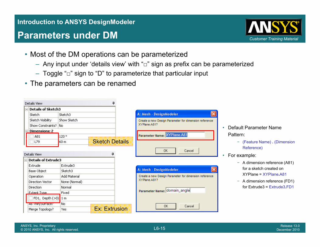
Customer Training MaterialParameters under DM
• Most of the DM operations can be parameterized– Any input under ‘details view’ with “□” sign as prefix can be parameterized– Toggle “□” sign to “D” to parameterize that particular inputgg g
• The parameters can be renamed
• Default Parameter Name Pattern:
Sketch Details − (Feature Name) . (Dimension Reference)
• For example:− A dimension reference (A81)
for a sketch created on XYPlane = XYPlane.A81
− A dimension reference (FD1) for Extrude3 = Extrude3.FD1
L6-15ANSYS, Inc. Proprietary© 2010 ANSYS, Inc. All rights reserved.
Release 13.0December 2010
Ex: Extrusion
Introduction to ANSYS DesignModeler
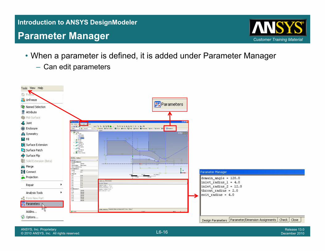
Customer Training MaterialParameter Manager
• When a parameter is defined, it is added under Parameter Manager– Can edit parameters
L6-16ANSYS, Inc. Proprietary© 2010 ANSYS, Inc. All rights reserved.
Release 13.0December 2010
Introduction to ANSYS DesignModeler
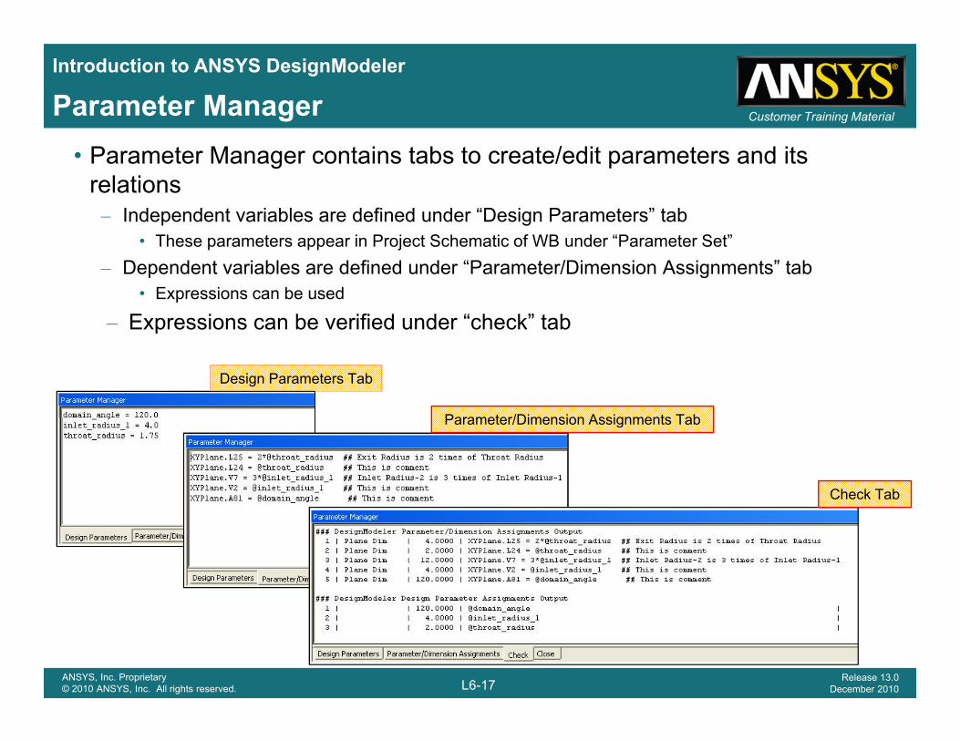
Customer Training MaterialParameter Manager• Parameter Manager contains tabs to create/edit parameters and its
relations– Independent variables are defined under “Design Parameters” tab
• These parameters appear in Project Schematic of WB under “Parameter Set”– Dependent variables are defined under “Parameter/Dimension Assignments” tab
• Expressions can be used
– Expressions can be verified under “check” tab– Expressions can be verified under check tab
Design Parameters Tab
Parameter/Dimension Assignments TabParameter/Dimension Assignments Tab
Check Tab
L6-17ANSYS, Inc. Proprietary© 2010 ANSYS, Inc. All rights reserved.
Release 13.0December 2010
Introduction to ANSYS DesignModeler
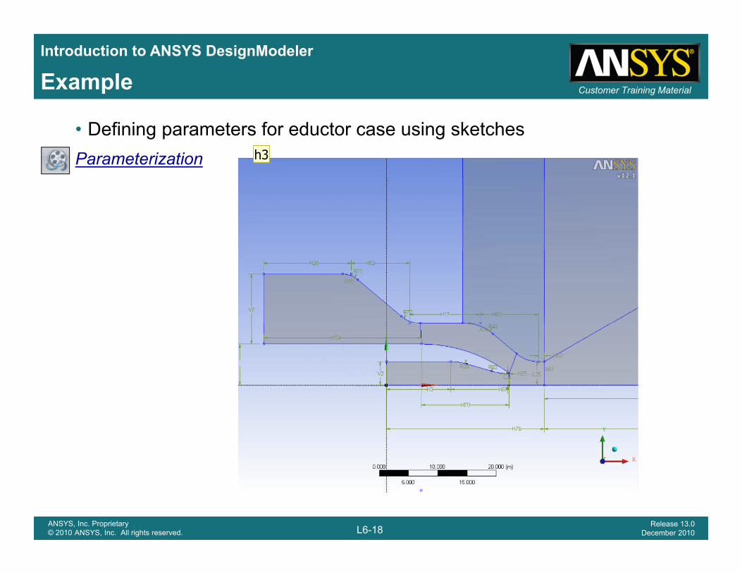
Customer Training MaterialExample
• Defining parameters for eductor case using sketchesParameterization
L6-18ANSYS, Inc. Proprietary© 2010 ANSYS, Inc. All rights reserved.
Release 13.0December 2010
h3
Slide 18
h3 change the starting slide for demomention appropriate slide heading for the demo slideshsahire, 11/26/2010
Introduction to ANSYS DesignModeler
Customer Training Material
APPENDIXAPPENDIX
L6-19ANSYS, Inc. Proprietary© 2010 ANSYS, Inc. All rights reserved.
Release 13.0December 2010
Introduction to ANSYS DesignModeler
Customer Training MaterialPre-requisites for CAD Connections– For all CAD packages
• CAD correctly installed and licensed • Correct ANSYS Inc. license
F CATIA– For CATIA• Compatible version of CATIA V5, CADNexus/CAPRI Gateway V3.08, IBM LUM
4.6.8 configured with a CATIA V5 (MD2, HD2, or ME2) license– For Pro/ENGINEERFor Pro/ENGINEER
• Parts must reside on a local or mapped drive • Filenames must contain all lowercase letters on the Linux platform
– For UG NX• Avoid setting Reader Save Part File to Yes on Linux platforms if a CAD file is open• NX 5.0.6 or higher is recommended for importing models containing spot welds• All bodies must be within a 1000 x 1000 x 1000 meter cube, centered about the
i i f th b l t di t torigin of the absolute coordinate system
For more information about license requirement, please see the documentation
L6-20ANSYS, Inc. Proprietary© 2010 ANSYS, Inc. All rights reserved.
Release 13.0December 2010
Introduction to ANSYS DesignModeler
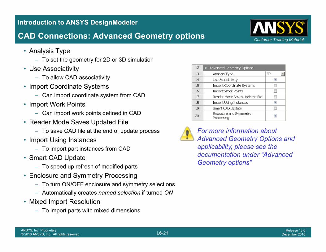
Customer Training MaterialCAD Connections: Advanced Geometry options
• Analysis Type– To set the geometry for 2D or 3D simulation
• Use Associativity – To allow CAD associativityTo allow CAD associativity
• Import Coordinate Systems– Can import coordinate system from CAD
• Import Work Points– Can import work points defined in CAD
• Reader Mode Saves Updated File– To save CAD file at the end of update process
• Import Using InstancesFor more information about Advanced Geometry Options and Import Using Instances
– To import part instances from CAD• Smart CAD Update
– To speed up refresh of modified partsE l d S t P i
y papplicability, please see the documentation under “Advanced Geometry options”
• Enclosure and Symmetry Processing– To turn ON/OFF enclosure and symmetry selections– Automatically creates named selection if turned ON
• Mixed Import Resolution
L6-21ANSYS, Inc. Proprietary© 2010 ANSYS, Inc. All rights reserved.
Release 13.0December 2010
– To import parts with mixed dimensions
Introduction to ANSYS DesignModeler
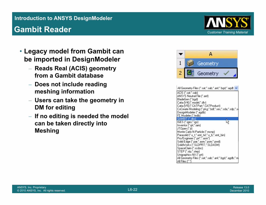
Customer Training MaterialGambit Reader
• Legacy model from Gambit can be imported in DesignModeler– Reads Real (ACIS) geometry
from a Gambit database– Does not include reading
hi i f timeshing information– Users can take the geometry in
DM for editingIf no editing is needed the model– If no editing is needed the model can be taken directly into Meshing
L6-22ANSYS, Inc. Proprietary© 2010 ANSYS, Inc. All rights reserved.
Release 13.0December 2010