Embed Size (px)
Citation preview
Parameter optimization and structural design of tuned mass damper for Shanghai centre tower
Xilin Lu and Junru Chen*,†
State Key Laboratory of Disaster Reduction in Civil Engineering, Tongji University, Shanghai, 200092, China
SUMMARY
With a height of 632 m, Shanghai centre tower (SHC), located in Lujiazui district of Shanghai, will be the highest building in China. A tuned mass damper (TMD) system will be set in the upper part to control the structural wind-induced response. The optimum control parameters of TMD were obtained through differ-ent optimization cases of TMD system parameters for wind vibration control. Then, Based on the concep-tual design of SHC TMD system, theoretical analysis and formula derivation of dual pendulum systems, which is an improved form of traditional pendulum systems, was carried out, and the fundamental design method and process of dual pendulum systems is proposed in the paper. Copyright © 2010 John Wiley & Sons, Ltd.
1. INTRODUCTION
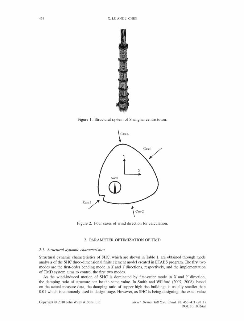
With a height of 632 m, Shanghai centre tower (SHC for short), located in Lujiazui fi nancial district of Shanghai, will be the highest building in China. Designed for commercial, offi ce, hotel and catering, etc., SHC is a composite high-rise building, the structural system of which is shown in Figure 1.
Shanghai is located in coastal area, and has been severely hitting by typhoon each year. Because of the extreme height, long natural period and low damping, the acceleration response of upper part of SHC, where will be six-star hotel, will exceed human comfort limit during wind events. Therefore, a tuned mass damper (TMD) system, the feasibility of which has been verifi ed in practical engineering (Fujino et al., 1996; Soong and Dargush et al., 1997; Ghorbani-Tanha et al., 2009), will be installed at a height of 565–569 m to suppress the wind-induced motion and to improve the residential comfort of SHC.
Finding the optimal control parameters is essential for designing a TMD system. Deriving analytical formulas of optimal system parameters have been studied in Bakrez and Jangid (2007), Krenk (2005) and Soong et al. (1997), etc. However, numerical methods (Lee et al., 2006) of fi nding optimal parameters are much simpler and more convenient to be applied in practical engineering without much complex formula derivation. As the exact spatial confi nement and optimizing conditions have not been explicit, the numerical optimization was carried out in four wind direction cases (see Figure 2) without any spatial confi nement in the paper.
The simple pendulum TMD system is commonly used in practical engineering which is represented by Taipei 101 tower (101 stories, 504 m). However, since the pendulum length is rather long when the traditional pendulum systems are used in high-rise buildings, quite large space is needed for the TMD system which leads to the increase of the costs. Hence, a new form of TMD called dual pendulum system will be used in SHC, and analysis and parameter design was carried out in the paper.
* Correspondence to: Junru Chen, State Key Laboratory of Disaster Reduction in Civil Engineering, Tongji University, Shanghai, 200092, China
† E-mail: [email protected]
Copyright © 2010 John Wiley & Sons, Ltd.
THE STRUCTURAL DESIGN OF TALL AND SPECIAL BUILDINGSStruct. Design Tall Spec. Build. 20, 453–471 (2011)Published online 1 December 2010 in Wiley Online Library (wileyonlinelibrary.com/journal/tal). DOI: 10.1002/tal.649
454 X. LU AND J. CHEN
Copyright © 2010 John Wiley & Sons, Ltd. Struct. Design Tall Spec. Build. 20, 453–471 (2011) DOI: 10.1002/tal
2. PARAMETER OPTIMIZATION OF TMD
2.1. Structural dynamic characteristics
Structural dynamic characteristics of SHC, which are shown in Table 1, are obtained through mode analysis of the SHC three-dimensional fi nite element model created in ETABS program. The fi rst two modes are the fi rst-order bending mode in X and Y directions, respectively, and the implementation of TMD system aims to control the fi rst two modes.
As the wind-induced motion of SHC is dominated by fi rst-order mode in X and Y direction, the damping ratio of structure can be the same value. In Smith and Willford (2007, 2008), based on the actual measure data, the damping ratio of supper high-rise buildings is usually smaller than 0.01 which is commonly used in design stage. However, as SHC is being designing, the exact value
Figure 1. Structural system of Shanghai centre tower.
X
Case 2
Case 4
Y
Case 1
North
Case 3
Figure 2. Four cases of wind direction for calculation.
DESIGN OF TMD FOR SHANGHAI CENTRE TOWER 455
Copyright © 2010 John Wiley & Sons, Ltd. Struct. Design Tall Spec. Build. 20, 453–471 (2011) DOI: 10.1002/tal
of structural damping ratio cannot be determined, the value 0.01 is adopted as the structural damping ratio in the paper according to wind-tunnel test results.
2.2. Theory of wind-induced vibration control
Because of the symmetry and high slenderness ratio, the SHC can be modeled as a vertical linear cantilever beam with n DOFs. It is assumed that a TMD whose mass, damping and stiffness are denoted by md, cd and kd respectively, is connected to the ith DOF of the SHC. The tower with the attached TMD can be treated as a n + 1 DOF system and its equation of motion can be written as
Mx Cx Kx P E+ + = ( ) + +( )t c kd dν ν (1)
m c k m E xd d d dν ν ν+ + = − { } (2)
where M, C and K are the mass, damping and stiffness matrixes of the structure respectively; x is a n-dimensional displacement vector of structure; xd is the displacement of TMD; P(t) is a n-dimensional wind excitation vector; E is a n-dimensional location vector of control force, whose ith component is 1 and the other components are 0; ν is the relative displacement of TMD with respect to the ith DOF of structure, given by ν = xd − xi.
Previous studies point out that the vibration of high-rise building is dominated by fi rst mode under wind excitation, so the wind-induced displacement of structure can be given as
x ≈ ( )j1 1q t (3)
where ϕ1 is the fi rst-order mode vector of structure; q1(t) is the fi rst-order generalized coordinate of structure.
Based on the orthogonality of vibration modes with respect to mass, damping and stiffness matrixes, the motion equations of system can be derived as
q q q F t i d d d1 1 1 1 12
1 1 1 122 2+ + = ( ) + +( )ζ ω ω μ ϕ ζ ω ν ω ν (4)
ν ζ ω ν ω ν ϕ+ + = −2 21 1d d d iq (5)
where ω1 and ζ1 is the circle frequency and damping ratio of mode 1 respectively; ωd and ζd is the circle frequency and damping ratio of TMD system respectively; μ1 is the generalized mass ratio of TMD mass with respect to the generalized mass of mode1; ϕ1i is the ith element of mode 1 vector; F1(t) is the generalized wind excitation, given by
F t t MT1 1 1( ) = ( )j P (6)
in which M1 denotes the generalized mass of mode1.Equations (4) and (5) can be expressed in the form of matrix as
1
1
2 0
0 21 1
21 1
1
1 1 1 1+⎡⎣⎢
⎤⎦⎥⎧⎨⎩
⎫⎬⎭+ ⎡⎣⎢
⎤⎦⎥
μ ϕ μ ϕϕ ν
ζ ωζ ω
i i
i d d
q q
νω
ω ν⎧⎨⎩
⎫⎬⎭+ ⎡⎣⎢
⎤⎦⎥⎧⎨⎩
⎫⎬⎭=
( )⎧⎨⎩
⎫⎬⎭
12
2
1 10
0 0d
q F t (7)
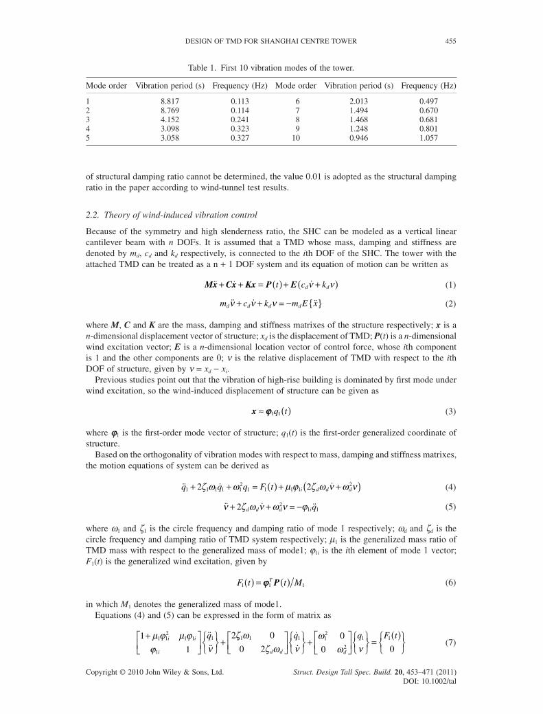
Table 1. First 10 vibration modes of the tower.
Mode order Vibration period (s) Frequency (Hz) Mode order Vibration period (s) Frequency (Hz)
1 8.817 0.113 6 2.013 0.4972 8.769 0.114 7 1.494 0.6703 4.152 0.241 8 1.468 0.6814 3.098 0.323 9 1.248 0.8015 3.058 0.327 10 0.946 1.057
456 X. LU AND J. CHEN
Copyright © 2010 John Wiley & Sons, Ltd. Struct. Design Tall Spec. Build. 20, 453–471 (2011) DOI: 10.1002/tal
Substituting eiωt for F1(t), the frequency response function of structural generalized coordinate and TMD relative displacement can be derived as the following equations, respectively
H iD
iq d d d1
122 2ω ω ω ζ ω ω( ) = −( ) + ( )[ ] (8)
H iD
iν ω ϕ ω( ) = 11
2 (9)
in which
D id d i d d
d i d
= − + +( )⋅ −
+ + +
ω ζ ω ζ ω μ ϕ ζ ω ω
ω ω μ ϕ ω ζ ω ζ
41 1 1 1
2 3
12 2
1 12 2
1 1
2
4( dd d d d d diω ω ζ ω ω ζ ω ω ω ω ω) ⋅ + +( )⋅ +21 1
212
12 22
Then, the transfer functions of structural generalized coordinate and TMD relative displacement can be obtained, respectively given by
H iE
q d1
212
1
2 2
212
1
214ω λ ω
ωζ λ ω
ω( ) = − ⎛⎝⎜
⎞⎠⎟
⎛⎝⎜
⎞⎠⎟+ ⎛
⎝⎜⎞⎠⎟
⎡
⎣⎢⎢
⎤
⎦⎥⎥
(10)
H iE
iν ω ϕ ωω
( ) = ⎛⎝⎜
⎞⎠⎟
212
1
41 (11)
in which
E
i d
=
⎛⎝⎜
⎞⎠⎟ − +( ) + +( )⎛⎝⎜
⎞⎠⎟ +
⎡
⎣⎢
ω
ωω
μ ϕ λ ζ ζ λ ωω
λ
14 1
4
1 12
12
1 11
2
121 4 1⎤⎤
⎦⎥
+ +( ) +( )⎛⎝⎜⎞⎠⎟ − +( )⎡
⎣⎢
⎤
⎦⎥
2
1 12
1 11
3
1 12
11
4 1 μ ϕ ζ λ ζ ωω
ζ λ ζ λ ωωi d d
22
⎧
⎨
⎪⎪
⎩
⎪⎪
⎫
⎬
⎪⎪
⎭
⎪⎪
where λ1 is the frequency ratio, given by λ1 = ωd / ω1.The transfer function of uncontrolled structure is defi ned as
H iq1
0 2
212 2
1 12
1
2ω
ω ω ζ ω ω( ) =
−( ) + ( ) (12)
According to random vibration theory, the variance of wind-induced displacement and acceleration of kth story is defi ned, respectively, as
σ ϕ ω ω ωx k q fk H i S d0 212 0 2
1( ) = ( ) ( )
−∞
+∞
∫ (13)
σ ϕ ω ω ω ωx k q fk H i S d0 212 4 0 2
1( ) = ( ) ( )
−∞
+∞
∫ (14)
where Sf(ω) is the generalized power spectrum density of wind load in respect of mode 1.For the structure controlled by TMD system, the response variance of structure and TMD can be
given by as the following equations
σ ϕ ω ω ωx k q fk H i S d( ) = ( ) ( )−∞
+∞
∫212 2
1 (15)
σ ϕ ω ω ω ωx k q fk H i S d( ) = ( ) ( )−∞
+∞
∫212 4 2
1 (16)
ν ω ω ων2 2= ( ) ( )
−∞
+∞
∫ H i S df (17)
DESIGN OF TMD FOR SHANGHAI CENTRE TOWER 457
Copyright © 2010 John Wiley & Sons, Ltd. Struct. Design Tall Spec. Build. 20, 453–471 (2011) DOI: 10.1002/tal
In order to evaluate the effectiveness of TMD on the response reduction of SHC, two non-dimensional evaluation criteria are considered, called displacement reduction ratio and acceleration reduction ratio respectively. The two evaluation criteria are defi ned by the TMD ability to reduce the response variance of structural displacement and acceleration and are given, respectively, by
δ σσ
xx
xk
k
k
22
0 2= ( )( )
(18)
δ σσ
xx
xk
k
k
22
0 2= ( )( )
(19)
2.3. Analysis of TMD parameters
In order to analyse the relation between TMD control performance and parameters of TMD systems, the wind-induced response of structure should be expressed in terms of mass ratio, damping ratio and frequency ratio etc. of TMD systems. According to Equations (13)–(16) the expressions of wind-induced response are in highly nonlinear form, and the integral parts are diffi cult to be solved, thus
simplifi cation of the integral part H i S dfω ω ω( ) ( )−∞
+∞
∫ 2 is the key for the optimal process.
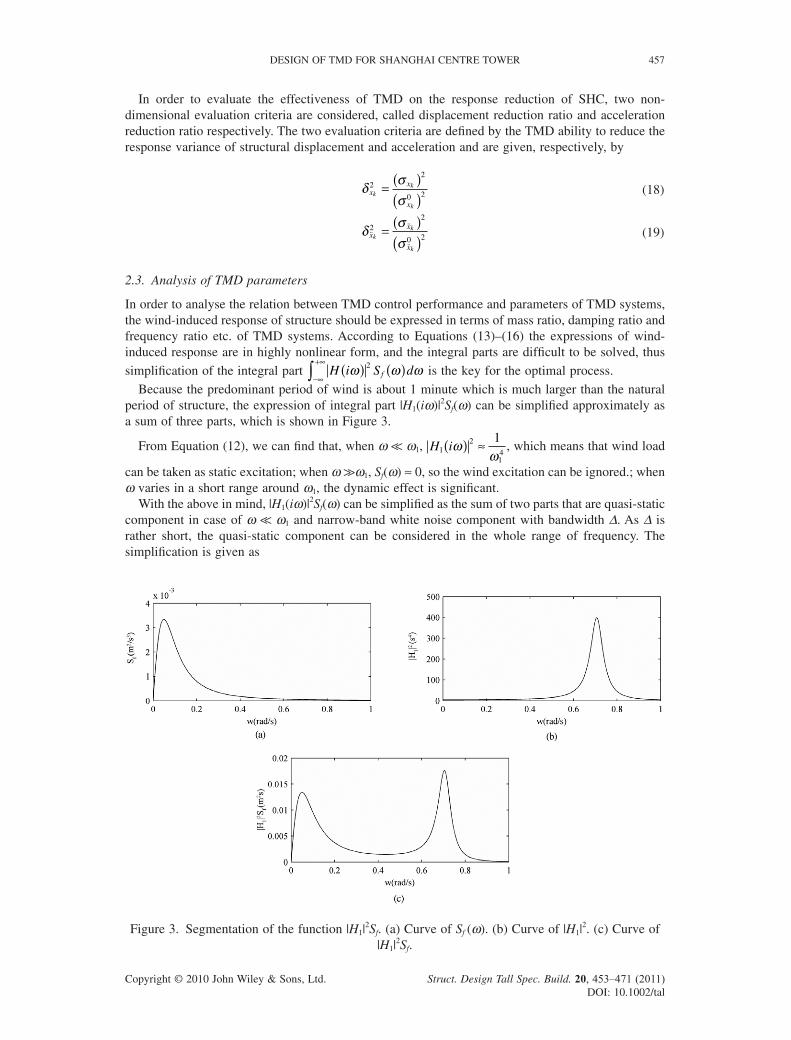
Because the predominant period of wind is about 1 minute which is much larger than the natural period of structure, the expression of integral part |H1(iω)|2Sf(ω) can be simplifi ed approximately as a sum of three parts, which is shown in Figure 3.
From Equation (12), we can fi nd that, when ω << ω1, H i12
14
1ωω
( ) ≈ , which means that wind load
can be taken as static excitation; when ω >> ω1, Sf(ω) ≈ 0, so the wind excitation can be ignored.; when ω varies in a short range around ω1, the dynamic effect is signifi cant.
With the above in mind, |H1(iω)|2Sf(ω) can be simplifi ed as the sum of two parts that are quasi-static component in case of ω << ω1 and narrow-band white noise component with bandwidth Δ. As Δ is rather short, the quasi-static component can be considered in the whole range of frequency. The simplifi cation is given as
Figure 3. Segmentation of the function |H1|2Sf. (a) Curve of Sf (ω). (b) Curve of |H1|
2. (c) Curve of |H1|
2Sf.
458 X. LU AND J. CHEN
Copyright © 2010 John Wiley & Sons, Ltd. Struct. Design Tall Spec. Build. 20, 453–471 (2011) DOI: 10.1002/tal
HS H i S d S d Sf f f1 12
14 1
14
12
1 1
2= ( ) ( ) = ( ) + ( )
( )−∞
+∞
−∞
+∞
∫ ∫ω ω ωω
ω ω ωω ζ
Δ (20)
The bandwidth of resonant component can be defi ned under the condition that the variance of white noise is equal to that of narrow-band white noise, which is given as (Wang ZM, 1994)
Δ =( )
( )
=−∞
+∞
∫ H i d12
14
12
1 11
2
ω ω
ω ζ
πζ ω (21)
in which, according to the integral formulas of complex-frequency response functions’ norm, the integration of transfer function |H1(iω)|2 is given as (Wang ZM, 1994)
H i d12
1 134
0ω ω πζ ω
ω( ) = >( )−∞
+∞
∫ (22)
Therefore
HS Sf114
1 13 1
1
4= + ( )ω
πζ ω
ω (23)
The simplifi ed form of H i S dq f1
2ω ω ω( ) ( )−∞
+∞
∫ was given in the same way as (Wang ZM, 1994)
HS Se
f214
13 1
1
4= + ( )ω
πζ ω
ω (24)
where ζe denotes the equivalent damping ratio of structure with TMD, which expresses as
ζ ζ μ ϕ ζ λ ζ ζ λζ λ ζ λ μ ϕ ζ λe
i d d
d i dA B C= + +( )
+ + −( )11 1
21 1 1
1 14
1 1 13
1 1 12
122 ++ +4 1
21ζ ζ λ ζd d
(25)
where A1 = (1 + μ1ϕ21i)
2, B1 = μ1ϕ21i + 4(1 + μ1ϕ2
1i)ζ 2d, C1 = 2ζ 2
1 + 2(1 + μ1ϕ21i)ζ2
d − 1.From Equations (23)–(25) we can fi nd that the equivalent damping ratio of structure will increase
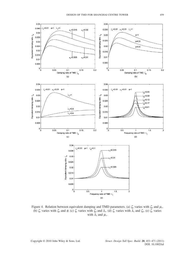
after a TMD system has been set, and the larger equivalent damping ratio is, the smaller wind-induced response is. Thus the equivalent damping ratio is an important index to evaluate the control perfor-mance of TMD. Figure 4, in which φ = ϕ1i, illustrates relation between the equivalent damping ratio and parameters of TMD system.
As the equivalent damping ratio relates to the parameters and the placement of TMD system, we can evaluate the control performance through study on relations between the equivalent damping ratio and parameters of TMD system. From Figure 4 we can fi nd that:
(1) Mass ratios have positive effect on the equivalent damping ratio.(2) There is an optimal damping ratio of TMD ζd,opt at which the equivalent damping ratio reaches
the maximum, while the other parameters of TMD system keep constant, and ζd,opt becomes larger and larger as the mass ratio μ1 increases.
(3) There is an optimal frequency ratio of TMD λ1,opt at which the equivalent damping ratio reaches the maximum, while the other parameters of TMD system keep constant, and λ1,opt is closed to but less than 1.
(4) With the same parameters of TMD system, the higher the TMD is placed, the better control performance will be achieved.
2.4. Numerical computation
The parameter optimization of TMD aims to fi nd out the optimal frequency ratio and damping ratio of TMD system.
DESIGN OF TMD FOR SHANGHAI CENTRE TOWER 459
Copyright © 2010 John Wiley & Sons, Ltd. Struct. Design Tall Spec. Build. 20, 453–471 (2011) DOI: 10.1002/tal
Figure 4. Relation between equivalent damping and TMD parameters. (a) ζe varies with ζd and μ1. (b) ζe varies with ζd and φ. (c) ζe varies with ζd and λ1. (d) ζe varies with λ1 and ζd. (e) ζe varies
with λ1 and μ1.
460 X. LU AND J. CHEN
Copyright © 2010 John Wiley & Sons, Ltd. Struct. Design Tall Spec. Build. 20, 453–471 (2011) DOI: 10.1002/tal
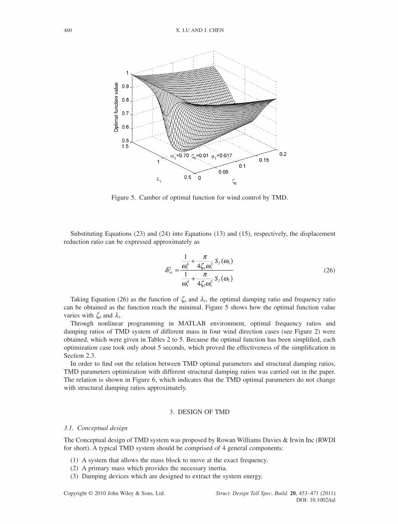
Substituting Equations (23) and (24) into Equations (13) and (15), respectively, the displacement reduction ratio can be expressed approximately as
δ ωπζ ω
ω
ωπζ ω
ωx
ef
f
k
S
S
2 14
13 1
14
1 13 1
14
14
=+ ( )
+ ( ) (26)
Taking Equation (26) as the function of ζd and λ1, the optimal damping ratio and frequency ratio can be obtained as the function reach the minimal. Figure 5 shows how the optimal function value varies with ζd and λ1.
Through nonlinear programming in MATLAB environment, optimal frequency ratios and damping ratios of TMD system of different mass in four wind direction cases (see Figure 2) were obtained, which were given in Tables 2 to 5. Because the optimal function has been simplifi ed, each optimization case took only about 5 seconds, which proved the effectiveness of the simplifi cation in Section 2.3.
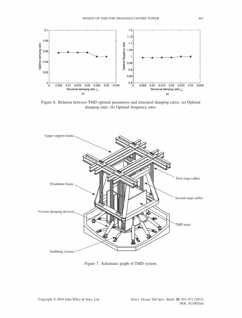
In order to fi nd out the relation between TMD optimal parameters and structural damping ratios, TMD parameters optimization with different structural damping ratios was carried out in the paper. The relation is shown in Figure 6, which indicates that the TMD optimal parameters do not change with structural damping ratios approximately.
3. DESIGN OF TMD
3.1. Conceptual design
The Conceptual design of TMD system was proposed by Rowan Williams Davies & Irwin Inc (RWDI for short). A typical TMD system should be comprised of 4 general components:
(1) A system that allows the mass block to move at the exact frequency. (2) A primary mass which provides the necessary inertia.(3) Damping devices which are designed to extract the system energy.
Figure 5. Camber of optimal function for wind control by TMD.
DESIGN OF TMD FOR SHANGHAI CENTRE TOWER 461
Copyright © 2010 John Wiley & Sons, Ltd. Struct. Design Tall Spec. Build. 20, 453–471 (2011) DOI: 10.1002/tal
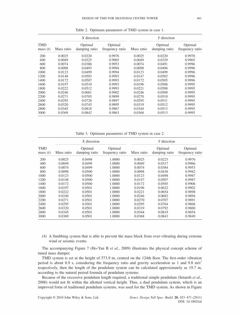
Table 2. Optimum parameters of TMD system in case 1.
TMD mass (t)
X direction Y direction
Mass ratioOptimal
damping ratioOptimal
frequency ratio Mass ratioOptimal
damping ratioOptimal
frequency ratio
200 0.0025 0.0220 0.9976 0.0025 0.0220 0.9970 400 0.0049 0.0325 0.9965 0.0049 0.0329 0.9965 600 0.0074 0.0386 0.9953 0.0074 0.0491 0.9996 800 0.0098 0.0493 0.9994 0.0098 0.0496 0.99961000 0.0123 0.0499 0.9994 0.0123 0.0499 0.99961200 0.0148 0.0503 0.9993 0.0147 0.0502 0.99961400 0.0172 0.0507 0.9993 0.0172 0.0505 0.99961600 0.0197 0.0510 0.9993 0.0196 0.0506 0.99951800 0.0222 0.0512 0.9993 0.0221 0.0508 0.99952000 0.0246 0.0681 0.9902 0.0246 0.0509 0.99952200 0.0271 0.0705 0.9899 0.0270 0.0510 0.99952400 0.0295 0.0726 0.9897 0.0295 0.0511 0.99952600 0.0320 0.0745 0.9895 0.0319 0.0512 0.99952800 0.0345 0.0818 0.9867 0.0344 0.0513 0.99953000 0.0369 0.0842 0.9863 0.0368 0.0513 0.9995
Table 3. Optimum parameters of TMD system in case 2.
TMD mass (t)
X direction Y direction
Mass ratioOptimal
damping ratioOptimal
frequency ratio Mass ratioOptimal
damping ratioOptimal
frequency ratio
200 0.0025 0.0498 1.0000 0.0025 0.0223 0.9976 400 0.0049 0.0499 1.0000 0.0049 0.0317 0.9966 600 0.0074 0.0499 1.0000 0.0074 0.0384 0.9953 800 0.0098 0.0500 1.0000 0.0098 0.0438 0.99421000 0.0123 0.0500 1.0000 0.0123 0.0498 0.99871200 0.0148 0.0500 1.0000 0.0147 0.0507 0.99871400 0.0172 0.0500 1.0000 0.0172 0.0585 0.99061600 0.0197 0.0501 1.0000 0.0196 0.0622 0.99021800 0.0222 0.0501 1.0000 0.0221 0.0654 0.98982000 0.0246 0.0501 1.0000 0.0246 0.0682 0.98942200 0.0271 0.0501 1.0000 0.0270 0.0707 0.98912400 0.0295 0.0501 1.0000 0.0295 0.0764 0.98662600 0.0320 0.0501 1.0000 0.0319 0.0792 0.98602800 0.0345 0.0501 1.0000 0.0344 0.0819 0.98543000 0.0369 0.0501 1.0000 0.0368 0.0843 0.9849
(4) A Snubbing system that is able to prevent the mass block from over-vibrating during extreme wind or seismic events.
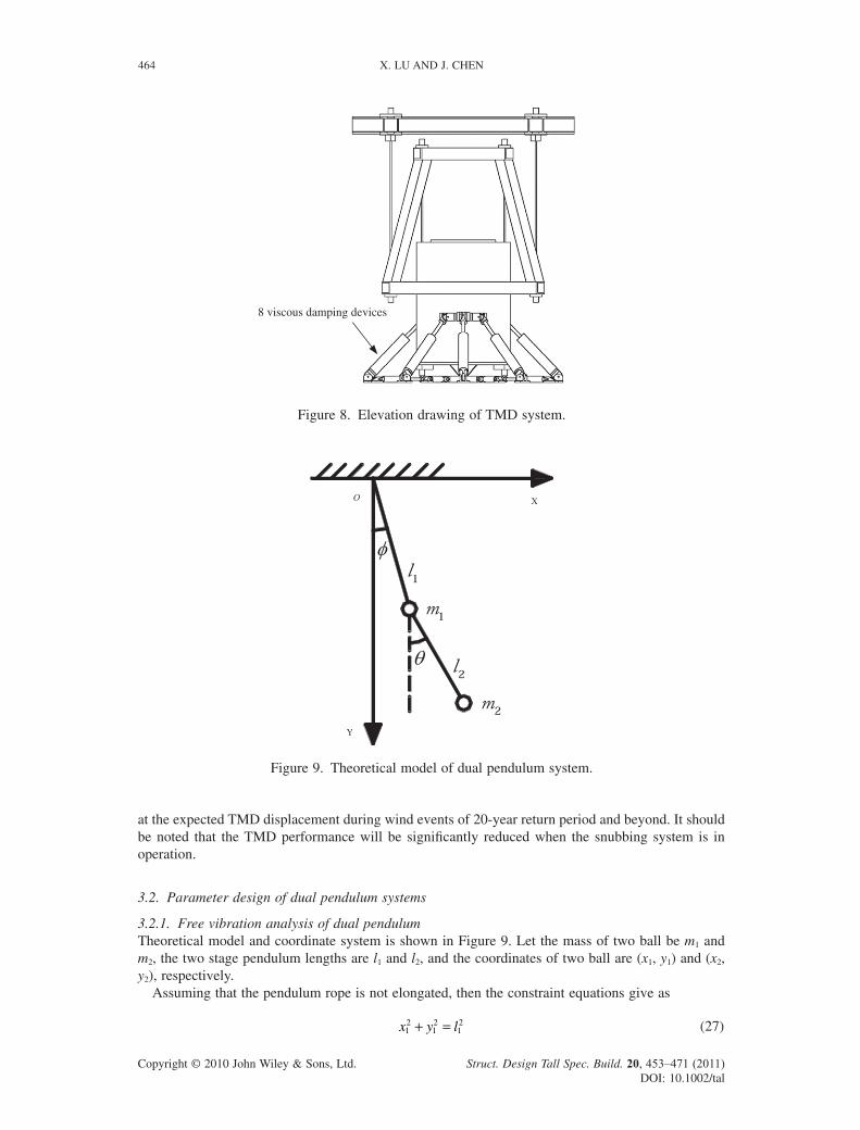
The accompanying Figure 7 (Ho-Yan B et al., 2009) illustrates the physical concept scheme of tuned mass damper.
TMD system is set at the height of 573.9 m, centred on the 124th fl oor. The fi rst-order vibration period is about 8.9 s, considering the frequency ratio and gravity acceleration as 1 and 9.8 m/s2 respectively, then the length of the pendulum system can be calculated approximately as 19.7 m, according to the natural period formula of pendulum systems.
Because of the excessive pendulum length required, a traditional simple pendulum (Setareh et al., 2006) would not fi t within the allotted vertical height. Thus, a dual pendulum system, which is an improved form of traditional pendulum systems, was used for the TMD system. As shown in Figure
462 X. LU AND J. CHEN
Copyright © 2010 John Wiley & Sons, Ltd. Struct. Design Tall Spec. Build. 20, 453–471 (2011) DOI: 10.1002/tal
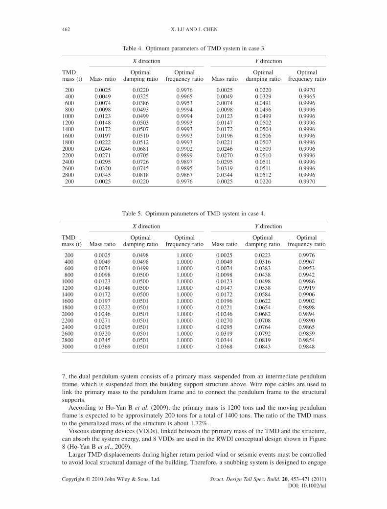
Table 4. Optimum parameters of TMD system in case 3.
TMD mass (t)
X direction Y direction
Mass ratioOptimal
damping ratioOptimal
frequency ratio Mass ratioOptimal
damping ratioOptimal
frequency ratio
200 0.0025 0.0220 0.9976 0.0025 0.0220 0.9970 400 0.0049 0.0325 0.9965 0.0049 0.0329 0.9965 600 0.0074 0.0386 0.9953 0.0074 0.0491 0.9996 800 0.0098 0.0493 0.9994 0.0098 0.0496 0.99961000 0.0123 0.0499 0.9994 0.0123 0.0499 0.99961200 0.0148 0.0503 0.9993 0.0147 0.0502 0.99961400 0.0172 0.0507 0.9993 0.0172 0.0504 0.99961600 0.0197 0.0510 0.9993 0.0196 0.0506 0.99961800 0.0222 0.0512 0.9993 0.0221 0.0507 0.99962000 0.0246 0.0681 0.9902 0.0246 0.0509 0.99962200 0.0271 0.0705 0.9899 0.0270 0.0510 0.99962400 0.0295 0.0726 0.9897 0.0295 0.0511 0.99962600 0.0320 0.0745 0.9895 0.0319 0.0511 0.99962800 0.0345 0.0818 0.9867 0.0344 0.0512 0.9996 200 0.0025 0.0220 0.9976 0.0025 0.0220 0.9970
Table 5. Optimum parameters of TMD system in case 4.
TMD mass (t)
X direction Y direction
Mass ratioOptimal
damping ratioOptimal
frequency ratio Mass ratioOptimal
damping ratioOptimal
frequency ratio
200 0.0025 0.0498 1.0000 0.0025 0.0223 0.9976 400 0.0049 0.0498 1.0000 0.0049 0.0316 0.9967 600 0.0074 0.0499 1.0000 0.0074 0.0383 0.9953 800 0.0098 0.0500 1.0000 0.0098 0.0438 0.99421000 0.0123 0.0500 1.0000 0.0123 0.0498 0.99861200 0.0148 0.0500 1.0000 0.0147 0.0538 0.99191400 0.0172 0.0500 1.0000 0.0172 0.0584 0.99061600 0.0197 0.0501 1.0000 0.0196 0.0622 0.99021800 0.0222 0.0501 1.0000 0.0221 0.0654 0.98982000 0.0246 0.0501 1.0000 0.0246 0.0682 0.98942200 0.0271 0.0501 1.0000 0.0270 0.0708 0.98902400 0.0295 0.0501 1.0000 0.0295 0.0764 0.98652600 0.0320 0.0501 1.0000 0.0319 0.0792 0.98592800 0.0345 0.0501 1.0000 0.0344 0.0819 0.98543000 0.0369 0.0501 1.0000 0.0368 0.0843 0.9848
7, the dual pendulum system consists of a primary mass suspended from an intermediate pendulum frame, which is suspended from the building support structure above. Wire rope cables are used to link the primary mass to the pendulum frame and to connect the pendulum frame to the structural supports.
According to Ho-Yan B et al. (2009), the primary mass is 1200 tons and the moving pendulum frame is expected to be approximately 200 tons for a total of 1400 tons. The ratio of the TMD mass to the generalized mass of the structure is about 1.72%.
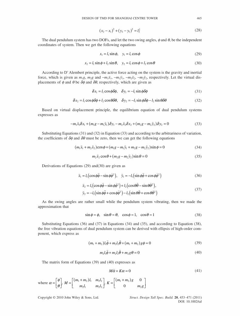
Viscous damping devices (VDDs), linked between the primary mass of the TMD and the structure, can absorb the system energy, and 8 VDDs are used in the RWDI conceptual design shown in Figure 8 (Ho-Yan B et al., 2009).
Larger TMD displacements during higher return period wind or seismic events must be controlled to avoid local structural damage of the building. Therefore, a snubbing system is designed to engage
DESIGN OF TMD FOR SHANGHAI CENTRE TOWER 463
Copyright © 2010 John Wiley & Sons, Ltd. Struct. Design Tall Spec. Build. 20, 453–471 (2011) DOI: 10.1002/tal
Figure 6. Relation between TMD optimal parameters and structural damping ratios. (a) Optimal damping ratio. (b) Optimal frequency ratio.
TMD mass
First stage cables
Second stage cables
Snubbing system
Upper support frame
Pendulum frame
Viscous damping deviced
Figure 7. Schematic graph of TMD system.
464 X. LU AND J. CHEN
Copyright © 2010 John Wiley & Sons, Ltd. Struct. Design Tall Spec. Build. 20, 453–471 (2011) DOI: 10.1002/tal
at the expected TMD displacement during wind events of 20-year return period and beyond. It should be noted that the TMD performance will be signifi cantly reduced when the snubbing system is in operation.
3.2. Parameter design of dual pendulum systems
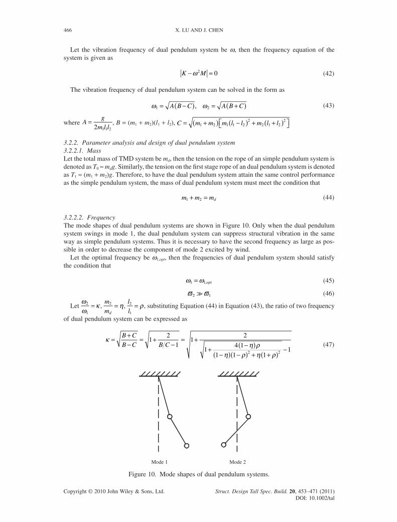
3.2.1. Free vibration analysis of dual pendulumTheoretical model and coordinate system is shown in Figure 9. Let the mass of two ball be m1 and m2, the two stage pendulum lengths are l1 and l2, and the coordinates of two ball are (x1, y1) and (x2, y2), respectively.
Assuming that the pendulum rope is not elongated, then the constraint equations give as
x y l12
12
12+ = (27)
8 viscous damping devices
Figure 8. Elevation drawing of TMD system.
Figure 9. Theoretical model of dual pendulum system.
DESIGN OF TMD FOR SHANGHAI CENTRE TOWER 465
Copyright © 2010 John Wiley & Sons, Ltd. Struct. Design Tall Spec. Build. 20, 453–471 (2011) DOI: 10.1002/tal
x x y y l2 12
2 12
22−( ) + −( ) = (28)
The dual pendulum system has two DOFs, and let the two swing angles, φ and θ, be the independent coordinates of system. Then we get the following equations
x l y l1 1 1 1= =sin , cosφ φ (29)
x l l y l l2 1 2 2 1 2= + = +sin sin , cos cosφ θ φ θ (30)
According to D’ Alembert principle, the active force acting on the system is the gravity and inertial force, which is given as m1g, m2g and −m1x1, −m1y1, −m2x2, −m2y2, respectively. Let the virtual dis-placements of φ and θ be δφ and δθ, respectively, which are given as
δ φδφ δ φδφx l y l1 1 1 1= = −cos , sin (31)
δ φδφ θδθ δ φδφ θδθx l l y l l2 1 2 2 1 2= + = − −cos cos , sin sin (32)
Based on virtual displacement principle, the equilibrium equation of dual pendulum systems expresses as
− + −( ) − + −( ) =m x x m g m y y m x x m g m y y1 1 1 1 1 1 1 2 2 2 2 2 2 2 0δ δ δ δ (33)
Substituting Equations (31) and (32) in Equation (33) and according to the arbitrariness of variation, the coeffi cients of δφ and δθ must be zero, then we can get the following equations
m x m x m g m y m g m y1 1 2 2 1 1 1 2 2 2 0+( ) + − + −( ) =cos sinφ φ (34)
m x m g m y2 2 2 2 2 0cos sinθ θ+ −( ) = (35)
Derivations of Equations (29) and(30) are given as
x l y l1 12
1 12= −( ) = − +( )cos sin , sin cosφφ φφ φφ φφ (36)
x l l
y l
2 12
22
2 1
= −( ) + −( )= −
cos sin cos sin ,
sin
φφ φφ θθ θθ
φφ φφ θθ θθ+( ) − +( )cos sin cos22
2l (37)
As the swing angles are rather small while the pendulum system vibrating, then we made the approximation that
sin , sin , cos , cosφ φ θ θ φ θ≈ ≈ ≈ ≈1 1 (38)
Substituting Equations (36) and (37) in Equations (34) and (35), and according to Equation (38), the free vibration equations of dual pendulum system can be derived with ellipsis of high-order com-ponent, which express as
m m l m l m m g1 2 1 2 2 1 2 0+( ) + + +( ) =φ θ φ (39)
m l m l m g2 1 2 2 2 0φ θ θ+ + = (40)
The matrix form of Equations (39) and (40) expresses as
M Kα α+ = 0 (41)
where αφθ
= ⎡⎣⎢⎤⎦⎥, M
m m l m l
m l m l=
+( )⎡⎣⎢
⎤⎦⎥
1 2 1 2 2
2 1 2 2
, Km m g
m g=
+( )⎡⎣⎢
⎤⎦⎥
1 2
2
0
0
466 X. LU AND J. CHEN
Copyright © 2010 John Wiley & Sons, Ltd. Struct. Design Tall Spec. Build. 20, 453–471 (2011) DOI: 10.1002/tal
Let the vibration frequency of dual pendulum system be ω, then the frequency equation of the system is given as
K M− =ω 2 0 (42)
The vibration frequency of dual pendulum system can be solved in the form as
ω ω1 2= −( ) = +( )A B C A B C, (43)
where Ag
m l l=
2 1 1 2
, B = (m1 + m2)(l1 + l2), C m m m l l m l l= +( ) −( ) + +( )⎡⎣ ⎤⎦1 2 1 1 22
2 1 22
3.2.2. Parameter analysis and design of dual pendulum system3.2.2.1. MassLet the total mass of TMD system be md, then the tension on the rope of an simple pendulum system is denoted as T0 ≈ mdg. Similarly, the tension on the fi rst stage rope of an dual pendulum system is denoted as T1 ≈ (m1 + m2)g. Therefore, to have the dual pendulum system attain the same control performance as the simple pendulum system, the mass of dual pendulum system must meet the condition that
m m md1 2+ = (44)
3.2.2.2. FrequencyThe mode shapes of dual pendulum systems are shown in Figure 10. Only when the dual pendulum system swings in mode 1, the dual pendulum system can suppress structural vibration in the same way as simple pendulum systems. Thus it is necessary to have the second frequency as large as pos-sible in order to decrease the component of mode 2 excited by wind.
Let the optimal frequency be ω1,opt, then the frequencies of dual pendulum system should satisfy the condition that
ω ω1 1= ,opt (45)
ϖ ϖ2 1 (46)
Let
ωω
κ2
1
= , m
md
2 = η, l
l2
1
= ρ , substituting Equation (44) in Equation (43), the ratio of two frequency
of dual pendulum system can be expressed as
κ
η ρη ρ η ρ
= +−
= +−
= ++ −( )
−( ) −( ) + +( )−
B C
B C B C1
2
11
2
14 1
1 1 112 2
(47)
Mode 1 Mode 2
Figure 10. Mode shapes of dual pendulum systems.
DESIGN OF TMD FOR SHANGHAI CENTRE TOWER 467
Copyright © 2010 John Wiley & Sons, Ltd. Struct. Design Tall Spec. Build. 20, 453–471 (2011) DOI: 10.1002/tal
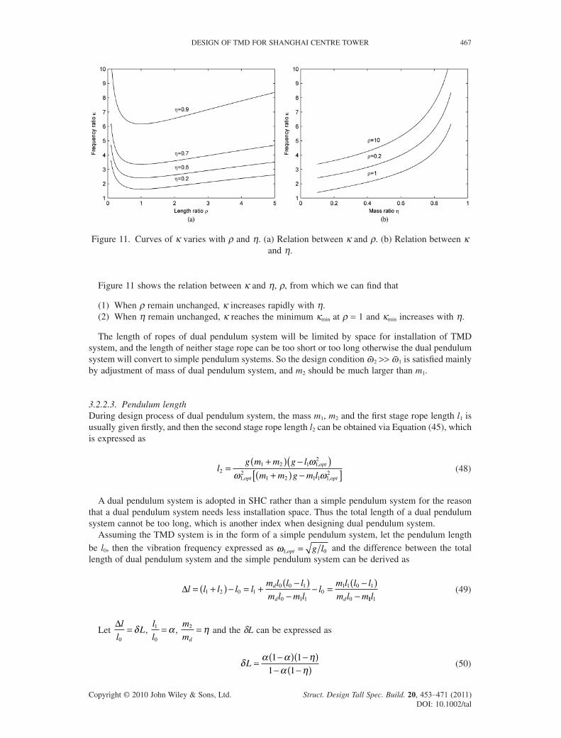
Figure 11 shows the relation between κ and η, ρ, from which we can fi nd that
(1) When ρ remain unchanged, κ increases rapidly with η.(2) When η remain unchanged, κ reaches the minimum κmin at ρ = 1 and κmin increases with η.
The length of ropes of dual pendulum system will be limited by space for installation of TMD system, and the length of neither stage rope can be too short or too long otherwise the dual pendulum system will convert to simple pendulum systems. So the design condition ω2 >> ω1 is satisfi ed mainly by adjustment of mass of dual pendulum system, and m2 should be much larger than m1.
3.2.2.3. Pendulum lengthDuring design process of dual pendulum system, the mass m1, m2 and the fi rst stage rope length l1 is usually given fi rstly, and then the second stage rope length l2 can be obtained via Equation (45), which is expressed as
lg m m g l
m m g m lopt
opt opt2
1 2 1 12
12
1 2 1 1 12
=+( ) −( )+( ) −[ ]
ωω ω
,
, ,
(48)
A dual pendulum system is adopted in SHC rather than a simple pendulum system for the reason that a dual pendulum system needs less installation space. Thus the total length of a dual pendulum system cannot be too long, which is another index when designing dual pendulum system.
Assuming the TMD system is in the form of a simple pendulum system, let the pendulum length
be l0, then the vibration frequency expressed as ω1 0,opt g l= and the difference between the total length of dual pendulum system and the simple pendulum system can be derived as
Δl l l l lm l l l
m l m ll
m l l l
m l md
d d
= +( ) − = + −( )−
− = −( )−1 2 0 1
0 0 1
0 1 10
1 1 0 1
0 11 1l (49)
Let Δl
lL
0
= δ , l
l1
0
= α , m
md
2 = η and the δL can be expressed as
δ α α ηα η
L = −( ) −( )− −( )1 1
1 1 (50)
Figure 11. Curves of κ varies with ρ and η. (a) Relation between κ and ρ. (b) Relation between κ and η.
468 X. LU AND J. CHEN
Copyright © 2010 John Wiley & Sons, Ltd. Struct. Design Tall Spec. Build. 20, 453–471 (2011) DOI: 10.1002/tal
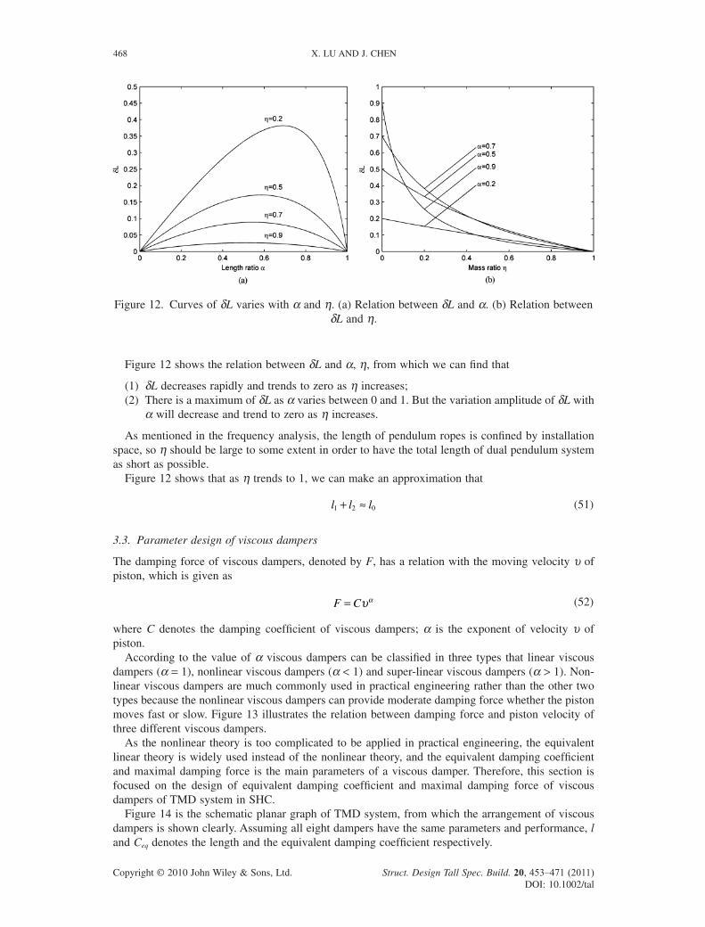
Figure 12 shows the relation between δL and α, η, from which we can fi nd that
(1) δL decreases rapidly and trends to zero as η increases;(2) There is a maximum of δL as α varies between 0 and 1. But the variation amplitude of δL with
α will decrease and trend to zero as η increases.
As mentioned in the frequency analysis, the length of pendulum ropes is confi ned by installation space, so η should be large to some extent in order to have the total length of dual pendulum system as short as possible.
Figure 12 shows that as η trends to 1, we can make an approximation that
l l l1 2 0+ ≈ (51)
3.3. Parameter design of viscous dampers
The damping force of viscous dampers, denoted by F, has a relation with the moving velocity υ of piston, which is given as
F C= υα (52)
where C denotes the damping coeffi cient of viscous dampers; α is the exponent of velocity υ of piston.
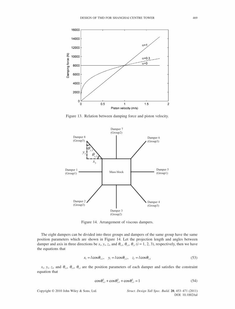
According to the value of α viscous dampers can be classifi ed in three types that linear viscous dampers (α = 1), nonlinear viscous dampers (α < 1) and super-linear viscous dampers (α > 1). Non-linear viscous dampers are much commonly used in practical engineering rather than the other two types because the nonlinear viscous dampers can provide moderate damping force whether the piston moves fast or slow. Figure 13 illustrates the relation between damping force and piston velocity of three different viscous dampers.
As the nonlinear theory is too complicated to be applied in practical engineering, the equivalent linear theory is widely used instead of the nonlinear theory, and the equivalent damping coeffi cient and maximal damping force is the main parameters of a viscous damper. Therefore, this section is focused on the design of equivalent damping coeffi cient and maximal damping force of viscous dampers of TMD system in SHC.
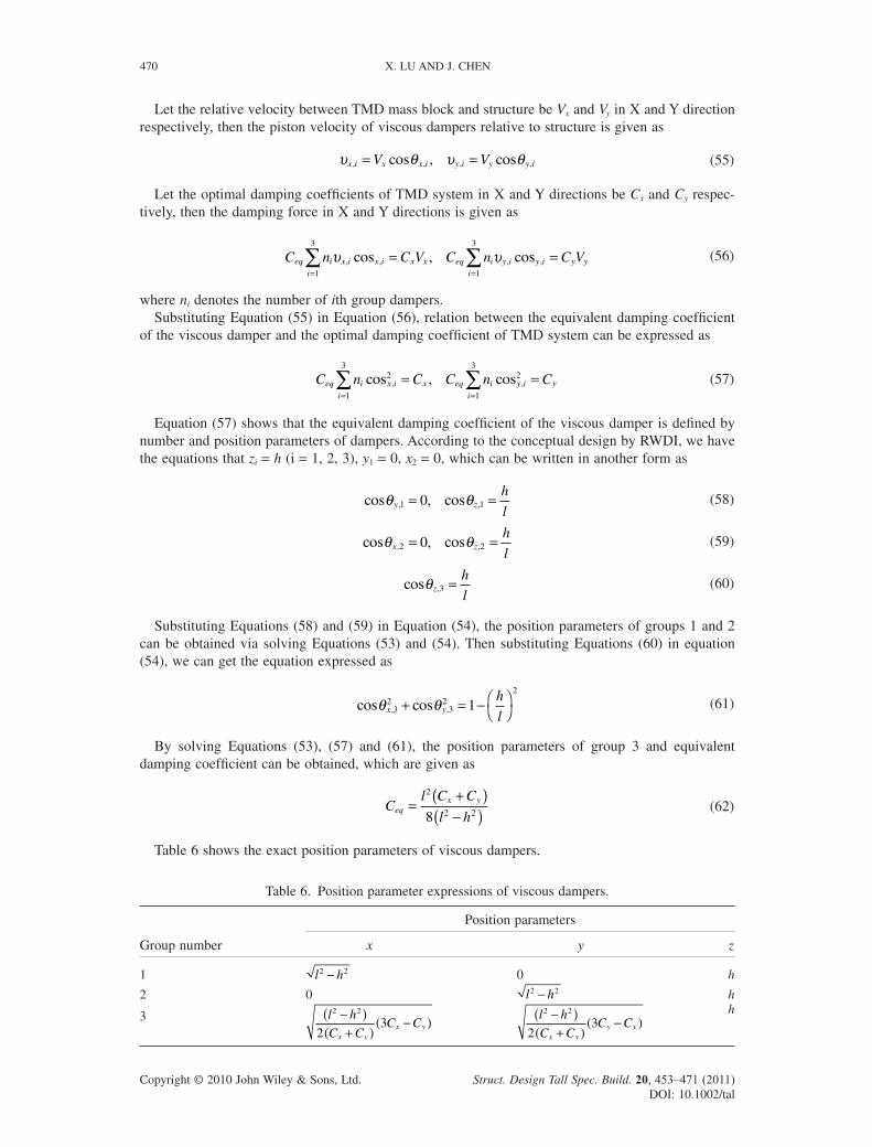
Figure 14 is the schematic planar graph of TMD system, from which the arrangement of viscous dampers is shown clearly. Assuming all eight dampers have the same parameters and performance, l and Ceq denotes the length and the equivalent damping coeffi cient respectively.
Figure 12. Curves of δL varies with α and η. (a) Relation between δL and α. (b) Relation between δL and η.
DESIGN OF TMD FOR SHANGHAI CENTRE TOWER 469
Copyright © 2010 John Wiley & Sons, Ltd. Struct. Design Tall Spec. Build. 20, 453–471 (2011) DOI: 10.1002/tal
The eight dampers can be divided into three groups and dampers of the same group have the same position parameters which are shown in Figure 14. Let the projection length and angles between damper and axis in three directions be xi, yi, zt, and θx,i, θy,i, θz,i (i = 1, 2, 3), respectively, then we have the equations that
x l y l z li x i i y i i z i= = =cos , cos , cos, , ,θ θ θ (53)
xi, yi, zi, and θx,i, θy,i, θz,i are the position parameters of each damper and satisfi es the constraint equation that
cos cos cos, , ,θ θ θx i y i z i2 2 2 1+ + = (54)
Figure 13. Relation between damping force and piston velocity.
Damper 1 (Group1)
Damper 7 (Group2)
Damper 8 (Group3)
Damper 5 (Group1)
Damper 3 (Group2)
Damper 6 (Group3)
Damper 2 (Group3)
Damper 4 (Group3)
Mass block
3x
3y ,3yθ,3xθ
Figure 14. Arrangement of viscous dampers.
470 X. LU AND J. CHEN
Copyright © 2010 John Wiley & Sons, Ltd. Struct. Design Tall Spec. Build. 20, 453–471 (2011) DOI: 10.1002/tal
Let the relative velocity between TMD mass block and structure be Vx and Vy in X and Y direction respectively, then the piston velocity of viscous dampers relative to structure is given as
υ θ υ θx i x x i y i y y iV V, , , ,cos , cos= = (55)
Let the optimal damping coeffi cients of TMD system in X and Y directions be Cx and Cy respec-tively, then the damping force in X and Y directions is given as
C n C V C n C Veq i x i x i x x
i
eq i y i y i y y
i
υ υ, , , ,cos , cos= == =∑ ∑
1
3
1
3
(56)
where ni denotes the number of ith group dampers.Substituting Equation (55) in Equation (56), relation between the equivalent damping coeffi cient
of the viscous damper and the optimal damping coeffi cient of TMD system can be expressed as
C n C C n Ceq i x i x
i
eq i y i y
i
cos , cos, ,2
1
32
1
3
= == =∑ ∑ (57)
Equation (57) shows that the equivalent damping coeffi cient of the viscous damper is defi ned by number and position parameters of dampers. According to the conceptual design by RWDI, we have the equations that zi = h (i = 1, 2, 3), y1 = 0, x2 = 0, which can be written in another form as
cos , cos, ,θ θy zh
l1 10= = (58)
cos , cos, ,θ θx zh
l2 20= = (59)
cos ,θzh
l3 = (60)
Substituting Equations (58) and (59) in Equation (54), the position parameters of groups 1 and 2 can be obtained via solving Equations (53) and (54). Then substituting Equations (60) in equation (54), we can get the equation expressed as
cos cos, ,θ θx yh
l3
23
22
1+ = − ⎛⎝⎞⎠
(61)
By solving Equations (53), (57) and (61), the position parameters of group 3 and equivalent damping coeffi cient can be obtained, which are given as
Cl C C
l heq
x y=+( )−( )
2
2 28 (62)
Table 6 shows the exact position parameters of viscous dampers.
Table 6. Position parameter expressions of viscous dampers.
Group number
Position parameters
x y z
1 l h2 2− 0 h
2 0 l h2 2− h
3 l h
C CC C
x yx y
2 2
23
−( )+( )
−( ) l h
C CC C
x yy x
2 2
23
−( )+( )
−( )h
DESIGN OF TMD FOR SHANGHAI CENTRE TOWER 471
Copyright © 2010 John Wiley & Sons, Ltd. Struct. Design Tall Spec. Build. 20, 453–471 (2011) DOI: 10.1002/tal
4. CONCLUDING REMARKS
From what has been written above the following conclusions can be drawn.
(1) The method of optimizing TMD parameters adopted in the paper proves to be effective and effi cient through numerical computation in MATLAB environment.
(2) There may be some difference between the real structural dynamic characteristics and that of calculation model. Besides, the relative displacement of TMD system will be probably confi ned by structural space, so the parameter optimization of TMD system must be checked with real constraints based on the actual structural characteristics during detail design of TMD system.
(3) The conceptual design of TMD system in the form of a dual pendulum system which will occupy less space is suitable for SHC and easy to readjust its frequency with the slight varia-tion of structural dynamic characteristics in service. The method of parameters design of dual pendulum system and viscous dampers proposed in the paper is simple for engineers to master and apply in practical engineering.
ACKNOWLEDGEMENTS
The research was partially supported by the Natural Science Foundation of China for Key Projects of Major Research Plan, Grant No. 90815029 and 51021140006. The authors also would like to acknowledge Architectural Design & Research Institute of Tongji University for providing them with the tower data.
REFERENCES
Bakrez SV, Jangid RS. 2007. Optimum parameters of tuned mass damper for damped main system. Structural Control and Health Monitoring 14: 448–470.
Fujino Y, Soong TT, Spencer Jr BF. 1996. Structural control: basic concepts and applications. In Proceedings of the 1996 ASCE Structures Congress, Chicago, IL.
Ghorbani-Tanha AK, Noorzad A, Rahimian M. 2009. Mitigation of wind-induced motion of Milad tower by tuned mass damper. The Structural Design of Tall and Special Buildings 18(4): 371–385.
Ho-Yan B, Smith AW, Haskett T, Kelly D, Irwin PA. 2009. Concept design of supplementary damping system[R]. Rowan Williams Davies & Irwin Inc, project number: #08-1440.
Krenk S. 2005. Frequency analysis of the tuned mass damper. Journal of Applied Mechanics 72: 936–942.Lee C, Chen Y, Chung L, Wang Y. 2006. Optimal design theories and applications of tuned mass dampers. Engineering
Structures 28: 43–53.Setareh M, Ritchey JK, Baxter AJ, Murray TM. 2006. Pendulum tuned mass dampers for fl oor vibration control. Journal of
Performance of Constructed Facilities 20(1): 64–73.Smith R, Willford M. 2008. Damping in tall buildings–uncertainties and solutions. 17th Congress of Iabse, Chicago, IL: 1–8.Smith R, Willford M. 2007. The damped outrigger concept for tall buildings. The Structural Design of Tall and Special Build-
ings 16: 501–517.Soong TT, Dargush GF. 1997. Passive energy dissipation systems in structural engineering. Wiley: Chichester, UK.Wang ZM. 1994. Study and design of TMD wind vibration control of TV tower structures. Chinese Journal of Building
Structure 15(5): 2–13. (in Chinese)