Embed Size (px)
Citation preview

Parameter Guide
2E

iii
About this manual
This
“Parameter Guide”
contains explanations and other information regarding the operations of the parameters and settings on the X50/microX. The explanations are organized by mode, page, and tab. Explanations and other information on the effects and their parameters are also provided for each effect.Refer to this guide when an unfamiliar parameter appears in the display, or when you need to know more about a partic-ular function.
Conventions in this manual
Abbreviations for the manuals, OG, PG
References to the manuals included with the X50/microX are abbreviated as follows.
OG
: Operation Guide
PG
: Parameter Guide
(
included in the CD-ROM)
Explanations specific to the X50 or microX
This parameter guide is written for both the X50 and the microX. Explanations that apply only to one or the other model are preceded by an indication of “
X50:
” or “
microX:
” in the text.
Switches and knobs [ ]
References to the buttons, dials, and knobs on the X50/microX’s panel are enclosed in square brackets [ ].
Parameters in the LCD display screen “ ”
Parameters displayed in the LCD screen are enclosed in double quotation marks “ ”.
Boldface type
Parameter values are printed in boldface type.Content that is of particular importance is also printed in boldface type.
Procedure steps
1
2
3
...
Steps in a procedure are listed as
1
2
3
...
☞
p.
■
,
☞
OG p.
■
,
☞■
–
■
From the left, these symbols indicate a reference page in the Parameter Guide, a reference page in the Operation Guide, and a parameter number.
Symbols , , , , ,
These symbols respectively indicate cautions, advice, MIDI-related explanations, a parameter that can be selected as an alternate modulation source, a parameter that can be selected as a dynamic modulation source, and a parameter that can use the BPM/MIDI Sync function.
Example screen displays
The values of the parameters shown in the example screens of this manual are only for explanatory purposes, and may not necessary match the values that appear in the LCD screen of your instrument.
MIDI-related explanations
CC#
is an abbreviation for Control Change Number.
In explanations of MIDI messages,
numbers in square brackets [ ]
always indicate hexadecimal numbers.
How to read the “Parameter Guide”
(example)
PROG 3: Ed–LFOs
Here you can make settings for the LFO that can be used to cyclically modulate the Pitch, Filter, and Amp of oscillators 1 and 2. There are two LFO units for each oscillator. By setting the LFO1 or LFO2 Intensity to a negative (–) value for Pitch, Filter, or Amp, you can invert the LFO waveform.
3–1: OS1LFO1 (OSC1 LFO1)
Indicates settings for the “OSC1 LFO1,” which is the first LFO that can be used for oscillator 1.
3–1a: OSC1 LFO1
Waveform [Triangle 0…Random6 (Vect.)]
■ 3–1: UTILITY
☞“Write Program” (0–1)
For details on how to select the desired utility function, refer to “PROG 0–1: UTILITY.”
Swap LFO 1&2This exchanges the settings of LFO 1 and 2. If LFO2 is selected in AMS1 (Freq. AMS1) or AMS2 (Freq. AMS2) of LFO1 Freq.Mod (3–1b), then these settings will be invalid for LFO2 after LFO1 and 2 have been exchanged. If you select this from the OSC1 LFO1 or OSC1 LFO2 page, LFO1 and LFO2 of OSC1 will be exchanged.
1 Select “Swap LFO 1&2” to access the dialog box.3–1a
3–1b
3–1c
Mode name
Page No.
Tab No.
Tab name
ParameterNo.
Parameter name
Page name
Utilty menu command name
Range of possible parameter values

iv
Table of Contents
1. Program mode........................... 1
PROG PAGE MENU .................................... 1
PROG 0: Play.............................................. 1
0–1: Program.......................................................... 1
0–2: P.Edit (Performance Editor) ........................ 3
0–3: Arp (Arp. Play).............................................. 5
microX: 0–4: Ext. Control...................................... 5
PROG 1: Ed–Basic ...................................... 6
1–1: Basic (Prog Basic) .......................................... 6
1–2: OSC1 ............................................................... 7
1–3: OSC2 ............................................................... 9
1–4: V.Zone (Velocity Zone)................................ 9
1–5: Audition ......................................................... 9
PROG 2: Ed–Pitch .................................... 10
2–1: OSC1 ............................................................. 10
2–2: OS1lfo (OSC1 LFO)..................................... 11
2–3: OSC2 ............................................................. 12
2–4: OS2lfo (OSC2 LFO)..................................... 12
2–5: EG (Pitch EG) ................................. 12
PROG 3: Ed–LFOs .................................... 14
3–1: OS1LFO1 (OSC1 LFO1) ................ 14
3–2: 1 LFO2 (OSC1 LFO2).................................. 15
3–3: 2 LFO1 (OSC2 LFO1).................................. 15
3–4: 2 LFO2 (OSC2 LFO2).................................. 15
PROG 4: Ed–Filter1.................................. 16
4–1: Basic .............................................................. 16
4–2: Mod.1 (Filter1 Modulation1)..................... 17
4–3: Mod.2 (Filter1 Modulation2)..................... 18
4–4: lfoMod (LFO Modulation)......................... 18
4–5: EG (Filter1 EG) ............................... 19
PROG 5: Ed–Filter2.................................. 21
5–1: Basic .............................................................. 21
5–2: Mod.1 (Filter2 Modulation1)..................... 21
5–3: Mod.2 (Filter2 Modulation2)..................... 21
5–4: lfoMod (LFO Modulation)......................... 21
5–5: EG (Filter2 EG) ............................... 21
PROG 6: Ed–Amp1/2 ............................... 21
6–1: Lvl/Pan (Amp1 Level/Pan)...................... 21
6–2: Mod. (Amp1 Modulation) ......................... 22
6–3: EG (Amp1 EG) ............................... 23
6–4: Lvl/Pan (Amp2 Level/Pan) ......................25
6–5: Mod. (Amp2 Modulation)..........................25
6–6: EG (Amp2 EG) ................................25
PROG 7: Ed–Arp/Ctrls (Arpeggiator/Controls).................................................. 25
7–1: Setup (Arpeg. Setup)...................................25
7–2: Zone (Scan Zone).........................................27
7–3: Controls.........................................................27
PROG 8: Ed–InsertFX .............................. 28
8–1: BUS ................................................................28
8–2: Setup..............................................................29
8–3: IFX (Insert Effect).........................................29
PROG 9: Ed–MasterFX ............................ 30
9–1: Setup..............................................................30
9–2: MFX 1 (Master Effect1) ...............................31
9–3: MFX 2 (Master Effect2) ...............................31
9–4: MEQ (Master EQ) ........................................31
2. Combination mode ................. 33
COMBI PAGE MENU ................................ 33
COMBI 0: Play.......................................... 33
0–1: Combi (Combination) .................................33
0–2: Prog (Timbre Program) ..............................35
0–3: Mix (Mixer)...................................................36
0–4: Arp. A (Arpeggio Play A) ..........................37
0–5: Arp. B (Arpeggio Play B)............................37
microX: 0–6: Ext. Control ....................................37
COMBI 1: Ed–Tone Adjust ...................... 38
1–1: Prog (Timbre Program) ..............................38
1–2: Mix (Mixer)...................................................38
1–3: TA1 (Tone Adjust 1)....................................38
1–4: TA2 (Tone Adjust 2)....................................38
1–5: TA3 (Tone Adjust 3)....................................38
COMBI 2: Ed–Timbre Param................... 40
2–1: MIDI ..............................................................40
2–2: OSC................................................................40
2–3: Pitch...............................................................41
2–4: Other..............................................................42
COMBI 3: Ed–MIDI Filter1....................... 42
3–1: MIDI 1–1 (MIDI Filter 1–1).........................42
3–2: MIDI 1–2 (MIDI Filter 1–2).........................43
3–3: MIDI 1–3 (MIDI Filter 1–3).........................43
3–4: MIDI 1–4 (MIDI Filter 1–4).........................43

COMBI 4: Ed–MIDI Filter2 ....................... 44
4–1: MIDI 2–1 (MIDI Filter 2–1) ........................ 44
4–2: MIDI 2–2 (MIDI Filter 2–2) ........................ 44
X50: 4–3: MIDI 2–3 (MIDI Filter2–3) ................. 44
X50: 4–4: MIDI 2–4 (MIDI Filter 2–4)................ 44
microX: 4–3: MIDI 2–3 (MIDI Filter2–3) ........... 44
COMBI 5: Ed–Key Zone ........................... 45
5–1: Key (Key Zone)............................................ 45
5–2: Slope (Key Slope) ........................................ 46
5–3: Review .......................................................... 46
COMBI 6: Ed–Vel Zone (Velocity Zone) ........ 46
6–1: Vel (Velocity Zone) ..................................... 46
6–2: Slope (Velocity Slope)................................. 47
6–3: Review .......................................................... 47
COMBI 7: Ed–Arp/Ctrls (Arpeggiator/Controls) .................................................. 47
7–1: Setup ............................................................. 47
7–2: Arp. A (Arpeggiator A).............................. 48
7–3: Arp. B (Arpeggiator B) ............................... 48
7–4: Zone (Scan Zone) ........................................ 49
7–5: Controls ........................................................ 50
COMBI 8: Ed–InsertFX............................. 50
8–1: BUS................................................................ 50
8–2: Setup ............................................................. 51
8–3: IFX (Insert Effect) ........................................ 52
COMBI 9: Ed–MasterFX........................... 52
9–1: Setup ............................................................. 52
9–2: MFX1 (Master Effect1)................................ 53
9–3: MFX2 (Master Effect2)................................ 53
9–4: MEQ (Master EQ)........................................ 53
3. Multi mode ...............................55
MULTI PAGE MENU ................................. 55
MULTI 0: Play........................................... 55
0–1: Multi.............................................................. 55
0–2: Prog..8 (Track Program T01...08) .............. 57
0–3: Prog..16 (Track Program T09...16) ............ 57
0–4: Mix..8 (Mixer T01...08)................................ 58
0–5: Mix..16 (Mixer T09...16).............................. 58
microX: 0–6: Ext. Control .................................... 59
MULTI 1: Tone Adjust ............................. 59
1–1: TA1..8 (Tone Adjust1) ................................ 59
1–2: TA1..16 (Tone Adjust1) .............................. 59
1–3: TA2..8 (Tone Adjust2) ................................ 59
1–4: TA2..16 (Tone Adjust2) .............................. 59
1–5: TA3..8 (Tone Adjust3) ................................ 59
1–6: TA3..16 (Tone Adjust3) .............................. 59
MULTI 2: Track Param............................. 61
2–1: MIDI..8 (MIDI T01–08)............................... 61
2–2: MIDI..16 (MIDI T09–16)............................. 61
2–3: OSC..8 (OSC T01–08).................................. 62
2–4: OSC..16 (OSC T09–16)................................ 62
2–5: Ptch..8 (Pitch T01–08) ................................. 62
2–6: Ptch..16 (Pitch T09–16) ............................... 62
2–7: Othr..8 (Other T01–08) ............................... 63
2–8: Othr..16 (Other T09–16) ............................. 63
MULTI 3: MIDI Filter1.............................. 64
3–1: M1–1..8 (MIDI Filter1–1 T01–08) .............. 64
3–2: 1–1..16 (MIDI Filter1–1 T09–16) ................ 64
3–3: 1–2..8 (MIDI Filter1–2 T01–08) .................. 64
3–4: 1–2..16 (MIDI Filter1–2 T09–16) ................ 64
3–5: 1–3..8 (MIDI Filter2–1 T01–08) .................. 64
3–6: 1–3..16 (MIDI Filter2–1 T09–16) ................ 64
3–7: 1–4..8 (MIDI Filter2–2 T01–08) .................. 65
3–8: 1–4..16 (MIDI Filter2–2 T09–16) ................ 65
MULTI 4: MIDI Filter2.............................. 65
4–1: M2–1..8 (MIDI Filter2–1 T01–08) .............. 65
4–2: 2–1..16 (MIDI Filter2–1 T09–16) ................ 65
4–3: 2–2..8 (MIDI Filter2–2 T01–08) .................. 66
4–4: 2–2..16 (MIDI Filter2–2 T09–16) ................ 66
X50: 4–5: 2–3..8 (MIDI Filter2–3 T01–08) ......... 66
X50: 4–6: 2–3..16 (MIDI Filter2–3 T09–16) ....... 66
X50: 4–7: 2–4..8 (MIDI Filter2–4 T01–08) ......... 66
microX: 4–5: 2–3..8 (MIDI Filter2–3 T01–08) .... 66
X50: 4–8: 2–4..16 (MIDI Filter2–4 T09–16) ....... 66
microX: 4–6: 2–3..16 (MIDI Filter2–3 T09–16) ..... 66
MULTI 5: Key Zone .................................. 67
5–1: Key..8 (Key Zone T01–08).......................... 67
5–2: Key..16 (Key Zone T09–16)........................ 67
5–3: Slp..8 (Key Slope T01–08) .......................... 67
5–4: Slp..16 (Key Slope T09–16) ........................ 67
5–5: Review.......................................................... 67
MULTI 6: Vel Zone (Velocity Zone) ........ 68
6–1: Vel..8 (Velocity Zone T01–08) ................... 68
6–2: Vel..16 (Velocity Zone T09–16) ................. 68
6–3: Slp..8 (Velocity Slope T01–08) ................... 68
6–4: Slp..16 (Velocity Slope T09–16) ................. 68
v

vi
6–5: Review.......................................................... 68
MULTI 7: Arp/Ctrls (Arpeggiator/Controls).......................... 69
7–1: Set..8 (Setup T01–08)................................... 69
7–2: Set..16 (Setup T09–16)................................. 69
7–3: Arp. A (Arpeggiator A).............................. 70
7–4: Arp. B (Arpeggiator B)............................... 70
7–5: Zone (Scan Zone) ........................................ 70
7–6: Controls ........................................................ 71
MULTI 8: InsertFX.................................... 72
8–1: BUS..8 (BUS T01...08).................................. 72
8–2: BUS..16 (BUS T09...16)................................ 72
8–3: Setup ............................................................. 72
8–4: IFX (Insert Effect) ........................................ 73
MULTI 9: MasterFX.................................. 73
9–1: Setup ............................................................. 73
9–2: MFX1 (Master Effect1) ............................... 74
9–3: MFX2 (Master Effect2) ............................... 74
9–4: MEQ (Master EQ) ....................................... 74
4. Global mode............................. 75
GLOBAL PAGE MENU .............................. 75
GLOBAL 0: System .................................. 75
0–1: Basic .............................................................. 75
0–2: Pref. (System Preference)........................... 78
0–3: Foot ............................................................... 80
GLOBAL 1: MIDI....................................... 81
1–1: MIDI.............................................................. 81
GLOBAL 2: User Scale ............................. 85
2–1: Octave........................................................... 85
2–2: All Notes ...................................................... 85
GLOBAL 3: Category Name .................... 86
3–1: P.0..7 (Prog.00...07)...................................... 86
3–2: P.8..15 (Prog.08...15).................................... 86
3–3: C.0..7 (Comb.00...07) ................................... 86
3–4: C.8..15 (Comb.08...15) ................................. 86
GLOBAL 4: DKit (Drum Kit) ..................... 86
4–1: High (High Sample) ................................... 86
4–2: Low (Low Sample) ..................................... 88
4–3: Voice (Voice/Mixer)................................... 88
GLOBAL 5: Arp.Pattern........................... 89
5–1: Setup..............................................................89
5–2: Edit ................................................................91
microX: GLOBAL 6: Ext. Control ............. 93
6–1: A (Knob 1–A, 2–A, 3–A, 4–A) ....................93
6–2: B (Knob 1–B, 2–B, 3–B, 4–B) .......................93
6–3: C (Knob 1–C, 2–C, 3–C, 4–C) .....................93
5. Demo Song............................... 95
Demo Song.............................................. 95
6. Effect Guide.............................. 97
Overview ................................................. 97
1. Effects in each mode .......................................97
2. Dynamic modulation (Dmod) .......................97
3. Effect I/O..........................................................97
Insert Effect (IFX) .................................... 98
1. In/Out...............................................................98
2. Routing..............................................................98
3. Mixer .................................................................99
4. Controlling the Insert Effects via MIDI......100
Master Effects (MFX1, 2) ...................... 100
1. In/Out.............................................................100
2. Routing............................................................101
3. Mixer ...............................................................102
4. Controlling the Master Effects via MIDI....102
Master EQ .............................................. 103
Individual Outputs ............................... 103
Filter/Dynamic ...................................... 104
00: No Effect .......................................................104
01: St.Amp Sim (Stereo Amp Simulation)......104
02: St.Compressor (Stereo Compressor).........104
03: St.Limiter (Stereo Limiter)..........................104
04: Mltband Limit (Multiband Limiter) .........105
05: St.Gate (Stereo Gate) ...................................106
06: OD/HiGain Wah (Overdrive/Hi.Gain Wah) .........................106
07: St.Para.4EQ (Stereo Parametric 4-Band EQ)..................107
08: St.Graphic7EQ (Stereo Graphic 7-Band EQ).......................108
09: St.Wah/AutoW(Stereo Wah/Auto Wah) ............................108

10: St.Rndm Filter (Stereo Random Filter)..... 109
11: St.Exct/Enhcr(Stereo Exciter/Enhancer) ......................... 110
12: St.Sub OSC (Stereo Sub Oscillator)........... 110
13: Talking Mod (Talking Modulator) ........... 111
14: St.Decimator (Stereo Decimator) .............. 112
15: St.AnalogRecd (Stereo Analog Record) ... 112
Pitch/Phase Mod. .................................. 113
16: St.Chorus (Stereo Chorus) ......................... 113
17: St.HarmnicCho (Stereo Harmonic Chorus)......................... 113
18: MltTap ChoDly (Multitap Chorus/Delay) .......................... 114
19: Ensemble ...................................................... 114
20: St.Flanger (Stereo Flanger) ........................ 115
21: St.Rndm Flang (Stereo Random Flanger) ........................... 115
22: St.Env.Flanger(Stereo Envelope Flanger).......................... 116
23: St.Phaser (Stereo Phaser) ........................... 116
24: St.Rndm Phasr (Stereo Random Phaser)............................. 117
25: St.Env.Phaser(Stereo Envelope Phaser) ........................... 117
26: St.BiphaseMod(Stereo Biphase Modulation)..................... 118
27: St.Vibrato (Stereo Vibrato)......................... 118
28: St.AutoFd Mod(Stereo Auto Fade Modulation) ................ 119
29: 2Voice Reso (2Voice Resonator)................ 119
30: Doppler......................................................... 120
31: Scratch........................................................... 121
Mod./P.Shift .......................................... 122
32: St.Tremolo (Stereo Tremolo) ..................... 122
33: St.Env.Tremlo(Stereo Envelope Tremolo) ........................ 122
34: St.Auto Pan (Stereo Auto Pan).................. 123
35: St.Phasr+Trml(Stereo Phaser + Tremolo) ......................... 123
36: St.Ring Mod (Stereo Ring Modulator) ..... 124
37: Detune .......................................................... 125
38: Pitch Shifter.................................................. 125
39: PitchShft Mod (Pitch Shift Modulation)............................. 126
40: Rotary SP (Rotary Speaker) ....................... 126
ER/Delay ................................................ 127
41: Early Reflect (Early Reflections) ............... 127
42: Auto Reverse ............................................... 128
43: LCR Delay (L/C/R Delay) ........................ 128
44: St/Cross Dly (Stereo/Cross Delay).......... 129
45: St.MltTap Dly (Stereo Multitap Delay) ... 129
46: St.Mod. Delay (Stereo Modulation Delay) ........................ 130
47: St.DynamicDly (Stereo Dynamic Delay)............................. 130
48: St.AutoPanDly(Stereo Auto Panning Delay) .................... 131
49: LCR BPM Delay (L/C/R BPM Delay)..... 131
50: St.BPM Delay (Stereo BPM Delay) ........... 132
51: Sequence Dly (Sequence Delay) ............... 132
Reverb ................................................... 133
52: Rev Hall (Reverb Hall)............................... 133
53: Rev Smth. Hall(Reverb Smooth Hall)................................. 133
54: Rev Wet Plate (Reverb Wet Plate) ............ 133
55: Rev Dry Plate (Reverb Dry Plate)............. 133
56: Rev Room (Reverb Room)......................... 134
57: Rev Brt. Room (Reverb Bright Room) ..... 134
Mono → Mono Chain............................ 135
58: P4EQ–Exciter(Parametric 4-Band EQ – Exciter)............. 135
59: P4EQ–Wah(Parametric 4-Band EQ – Wah/Auto Wah) . 135
60: P4EQ–Cho/Fl(Parametric 4-Band EQ – Chorus/Flanger) . 136
61: P4EQ–Phaser (Parametric 4-Band EQ – Phaser) ............. 136
62: P4EQ–M.Dly (Parametric 4-Band EQ – Multitap Delay) ... 137
63: Comp–Wah(Compressor – Wah/Auto Wah).............. 137
64: Comp–AmpSim(Compressor – Amp Simulation) ............. 138
65: Comp–OD/HG(Compressor – Overdrive/Hi.Gain) ........ 138
66: Comp–P4EQ(Compressor – Parametric 4-Band EQ) ... 138
67: Comp–Cho/Fl(Compressor – Chorus/Flanger).............. 139
68: Comp–Phaser (Compressor – Phaser) ..... 139
69: Comp–M.Dly(Compressor – Multitap Delay)................ 140
70: Limit–P4EQ(Limiter – Parametric 4-Band EQ)............ 140
71: Limit–Cho/Fl(Limiter – Chorus/Flanger) ...................... 141
72: Limit–Phaser (Limiter – Phaser)............... 141
73: Limit–M.Dly (Limiter – Multitap Delay) ........................ 142
74: Exct–Comp (Exciter – Compressor) ......... 142
75: Exct–Limiter (Exciter – Limiter) ............... 142
76: Exct–Cho/Fl(Exciter – Chorus/Flanger) ....................... 143
vii

viii
77: Exct–Phaser (Exciter – Phaser).................. 143
78: Exct–M.Dly (Exciter – Multitap Delay) ... 143
79: OD/HG–AmpSim(Overdrive/Hi.Gain – Amp Simulation).... 144
80: OD/HG–Cho/Fl(Overdrive/Hi.Gain – Chorus/Flanger) .... 144
81: OD/HG–Phaser(Overdrive/Hi.Gain – Phaser).................. 145
82: OD/HG–M.Dly (Overdrive/Hi.Gain – Multitap Delay)... 145
83: Wah–AmpSim(Wah/Auto Wah – Amp Simulation) ...... 146
84: Deci–AmpSim(Decimator – Amp Simulation)................. 146
85: Deci–Comp(Decimator – Compressor) ........................ 146
86: AmpSim–Trml(Amp Simulation – Tremolo) .................... 147
87: Cho/Fl–M.Dly(Chorus/Flanger – Multitap Delay)......... 147
88: Phasr–Cho/Fl(Phaser – Chorus/Flanger)........................ 148
89: Reverb–Gate ................................................ 148
Master EQ .............................................. 149
Master EQ .......................................................... 149
7. Appendices ............................ 151
Alternate Modulation Source (AMS)........ 151
About Alternate Modulation ...........................151
About Alternate Modulation Sources ............151
AMS (Alternate Modulation Source) List .............152
Alternate Modulation settings.........................154
The effect of alternate modulation on various parameters, and example applications.....154
Dynamic Modulation Source (Dmod) ....... 157
Dynamic Modulation Source List ...................158
About the BPM/MIDI SYNC function...........160
X50: SW1/2 Assign ................................ 161
SW1, SW2 Assign List.......................................161
Knob 1...4 B Assign ............................... 162
Realtime Control Knobs B Assign List ...........162
Foot Switch Assign ............................... 164
Foot Switch Assign List ....................................164
Foot Pedal Assign ................................. 165
Foot Pedal Assign List ......................................165
MIDI transmission when the X50/microX’s controllers are operated ...................... 166
X50/microX operations when control changes are transmitted/received ...... 168
MIDI applications.................................. 171
■ Messages transmitted and received by this instrument......................................................171
Various messages ................................. 180
X50, microX MUSIC SYNTHSIZER MIDI IMPLEMENTATION................................ 181
Index...................................................... 184
• Apple, Mac and Audio Units are trademarks of Apple Computer, Inc., registered in the US. and other countries.
• Windows XP is a registered trademark of Microsoft Corporation in the U.S. and other counties.
• VST is a trademark of Steinberg Media Technologies GmbH. • RTAS is a registered trademark of Avid Technology, Inc., or its
subsidiaries or divisions. • All other product and company names are trademarks or regis-
tered trademarks of their respective holders.

PR
OG
1. Program mode
0 1
23
45
67
89
PROG PAGE MENU
Use the following procedure to select the desired page from within the current mode.
1 Press the [MENU/OK] button to access the “PAGE MENU.”The “PAGE MENU” will show an abbreviated name for each page.
2 Use the ClickPoint [√][®][π][†] to select a page.
3 Press the center of the ClickPoint to access the page.
4 If the selected page is divided into multiple pages, use the PAGE [+][–] buttons to select the page you want.
Other ways to select a page
• Use the PAGE [+][–] buttons to move between tabs of a page.
• Hold down the [MENU/OK] button and use the PAGE [+][–] buttons to move forward or backward in the order of pages 0→1→2→3 etc.
X50: • Hold down the [MENU/OK] button and press one of
the numeric buttons [0]–[9] to move to the corresponding page number. For example if you want to move to the PROG 3: Ed–LFOs page, hold down the [MENU/OK] button and press numeric button [3].
PROG 0: Play
In this display page you can select and play programs.
All MIDI data in PROG 0: Play is transmitted and received on the Global MIDI Channel (☞GLOBAL 1–1a).
0–1: Program
X50
microX
0–1a: Bank, Program Select, Category, Cat. Hold, 10’s Hold, � (Tempo)
Bank X50: [Bank A...D, G, g(d)]microX: [Bank A...E, G, g(d)]
This is the program bank display.
X50: Use the PROG BANK [A]–[GM] buttons to select the bank. The X50 provides rewritable banks A, B, C, and D, each containing 128 programs (total 512). As for non-rewrit-able program areas, it provides banks G (capital programs for GM), and bank g(d) (drums).
X50 Bank List
Bank G will toggle between the GM and g(d) banks each time you press the PROG BANK [GM] button.
G→g(d)→G→g(d)→G…
Play 0: Play Select and play programs.Use the Performance Editor for easy edit-ing, and to do simple editing of arpeggio patterns.microX: Select an external control set. (☞p.1)
Basic 1: Ed–Basic Set basic program parameters such as Oscillator and Multisample. (☞p.6)
Pitch 2: Ed–Pitch Pitch settings. Pitch EG settings. (☞p.10)
LFOs 3: Ed–LFOs Type and speed settings etc. for the two LFOs provided for each oscillator. (Make settings in the pitch, filter, and amp pages to specify the depth of the LFO settings you make here.) (☞p.14)
Filter1 4: Ed–Filter1 Filter 1 (tone) settings. Filter EG settings. (☞p.16)
Filter2 5: Ed–Filter2 Filter 2 (tone) settings. Filter EG settings. (☞p.21)
Amp1/2 6: Ed–Amp1/2 Amp 1 and Amp 2 (volume) settings. Amp EG, pan (position) settings. (☞p.21)
Arp/Controls 7: Ed–Arp/Ctrls Arpeggiator settings. (Shared with 0: Play parameters. You may edit either.) Controller settings. (☞p.25)
Insert Effect 8: Ed–InsertFX Select the BUS and master effect send level for the oscillator output. Insert Effect routing, selection and set-tings. (☞p.28)
Master Effect 9: Ed–MasterFX Master Effect selection and settings. Mas-ter EQ settings. (☞p.30)
Bank A
for preloaded programs(for user programs)
Bank B
Bank C
Bank D
Bank G GM capital program
Bank g(d) GM drums program
0–1a
0–1b
0–1a
0–1b
1

2
microX: Use the PROGRAM [A]–[GM] buttons to select the bank. The microX provides rewritable banks A, B, C, D, and E, each containing 128 programs (total 640). As for non-rewritable program areas, it provides banks G (capital pro-grams for GM), and bank g(d) (drums). If you press a PRO-GRAM [A]–[GM] button, you will automatically enter Program mode even if you had been in a different mode.
microX Bank List
Bank G will toggle between the GM and g(d) banks each time you press the PROGRAM [GM] button.
G→g(d)→G→g(d)→G…
Program SelectX50: [(A…D)0…127: name, (G, g(d))1…128: name]microX: [(A…E)0…127: name, (G, g(d))1…128: name]Here you can select a program.Choose this parameter, and use one of the following meth-ods to select a program.
X50: • Turn the [VALUE] dial.• Use the [INC][DEC] buttons.• Use the numeric buttons [0]–[9] to enter a program
number, and press the [ENTER] button to finalize the number.
• Press the center of the ClickPoint to highlight the field, then use [π][†] to select a program, and press the center to finalize your selection.
• 10’s HOLD (☞p.2)• Use PROG BANK [A]–[GM] to select a bank (☞p.1)• Use “Select by Category” to select by category (☞p.2)• Use the foot switch (☞p.80, 164)• Receive a MIDI program change (☞p.171)
microX: • Turn the [VALUE] dial.• Press the center of the ClickPoint to highlight the field,
then use [π][†] to select a program, and press the center to finalize your selection.
• Use “Select by Category” to select by category (☞p.2)• Use the [CATEGORY] button and PROGRAM/
COMBINATION buttons to select by category (☞p.2)• Use the foot switch (☞p.80, 164)• Receive a MIDI program change (☞p.171)
You can receive MIDI program changes from a con-nected external MIDI device, or use a foot switch to select programs. (☞p.80 “Foot SW Assign” (GLOBAL 0–3a), p.164 “Foot Switch Assign List”)
Category [00...15: name]Selects the program category.All programs are classified into one of sixteen categories. You can select the desired category, and then choose pro-grams from that category.To select a program by category, use the procedure described below.
To assign a category to each program, use the “Write Program” (0–1) dialog box. To change the name of a cat-egory, use “Category Name Prog. 00–07, 08–15” (☞GLOBAL 3–1/2).
X50: Cat. HOLD (Category Hold)
1 Press the [./HOLD] button to display . The category will be held (fixed).
2 Use the ClickPoint [√][®][π][†] to choose “Category,” and use the [INC][DEC] buttons or the [VALUE] dial to select a category.
3 Use the ClickPoint [√][®][π][†] to choose “Program Select,” and use the [INC][DEC] buttons or the [VALUE] dial to successively select programs in that category.
4 To cancel, press the [./HOLD] button twice to turn off the display.
If you press the [./HOLD] button in PROG 0: Play, the selection will cycle in the order of →
→ Cancel.
Select by Category1 Press the [CATEGORY] button to access the category
menu (Prog/Category).
X50
microX
Alternatively, you can access the category menu by pressing the [UTILITY] button and choosing “Select by Category” from the utility menu.
2 Use ClickPoint [√] to select “Prog/Category,” and use the [VALUE] dial to select a category.
3 Use ClickPoint [π][†] to select a program. Alternatively, use the ClickPoint [®] to choose “Sel (Select),” and use the [VALUE] dial to select a program.
4 Press the [MENU/OK] button to execute, or press the [EXIT/CANCEL] button if you decide not to execute.
microX: Category & Bank
1 Press the [CATEGORY] button to access the category menu (Prog/Category).
2 Note the categories shown below the PROGRAM buttons or COMBINATION buttons, and press the corresponding button for the desired category. You can also use the [PAGE+][PAGE–] buttons to step through the categories one by one.
3 Use the [VALUE] dial to select a program.
4 Press the [MENU/OK] button to execute, or press the [EXIT/CANCEL] button if you decide not to execute.
X50: 10’s HOLD
1 Press the [./HOLD] button to make the indi-cation appear.
Bank A
for preloaded programs(for user programs)
Bank B
Bank C
Bank D
Bank E
Bank G GM capital program
Bank g(d) GM drums program

3
PR
OG
0 1
23
45
67
89
The ten’s place of the program number will be fixed.
2 Now you can press a numeric button [0]–[9] to enter the one’s place in a single action.
3 You can use the [INC][DEC] buttons to change the ten’s place.
4 To defeat 10’s HOLD, press the [./HOLD] button to make the indication disappear.
� (Tempo) [040...240, EXT]This sets the tempo of the arpeggiator. The tempo can also be adjusted by the REALTIME CONTROLS C-mode [TEMPO] knob.EXT is shown if “MIDI Clock” (GLOBAL 1–1a) is set to Ext-MIDI or Ext-USB, or if it is set to Auto and the unit is oper-ating as a slave. The arpeggiator will synchronize to MIDI clock messages from an external MIDI device.You can also set this parameter from 7: Ed–Arp/Ctrls.
X50: You can tap the [ENTER] button several times to set the tempo to the corresponding interval. Alternatively, if you set the GLOBAL 0–3: Foot page “Foot SW Assign” parameter to Tap Tempo, you can specify the tempo by tap-ping your foot on a pedal switch connected to the ASSIGN-ABLE SWITCH jack.
microX: If you set the GLOBAL 0–3: Foot page “Foot SW Assign” parameter to Tap Tempo, you can specify the tempo by tapping your foot on a pedal switch connected to the ASSIGNABLE SWITCH jack.
0–1b: Program Information
X50: This area shows the functions that are assigned to the assignable switches [SW1] and [SW2], and to the REALTIME CONTROLS B-mode [ASSIGNABLE 1]–[ASSIGNABLE 4] knobs of the selected program.
microX: This area shows the functions that are assigned to the REALTIME CONTROLS B-mode [ASSIGNABLE 1]–[ASSIGNABLE 4] knobs.
■ 0–1: UTILITY
Use the following procedure to select the desired utility.
1 Press the [UTILITY] button to access the utility menu.
2 Use the ClickPoint to select the utility that you want to execute.
3 Press the center of the ClickPoint to access the dialog box.
X50: Utilities up to number 10 can also be selected by hold-ing down the [ENTER] button and pressing the correspond-ing numeric button [0]–[9] to access the dialog box.
Write ProgramIf you wish to save a program, be sure to write it into the memory of the X50/microX.An edited program cannot be recovered if you do not write it to memory before turning off the power or selecting another program.
If you want to write a program, you must first turn off the memory protect setting in Global mode. (☞p.79 GLOBAL 0–2b: Memory Protect)
1 Select “Write Program” to access the dialog box.
2 The upper line shows the bank, program number and program name.
3 In “Category,” specify the category of the program that you are writing.The category selected here can be used to find this pro-gram when selecting a program in Program, Combina-tion, Multi.
With the factory settings, the program categories have been given the names of instruments etc., but you can use “Category Name Prog.00–07, 08–15” (GLOBAL 3–1/2) to modify these category names.
4 In “To” to specify the writing destination.
X50: You can use the PROG BANK [A]–[D] buttons to select a bank. You can also use the numeric buttons [0]–[9] and [ENTER] button to select a program number.
You can’t write to bank G or g(d). If you’ve edited a program from bank G or g(d) and want to write it, you’ll need to write it to a bank other than the GM bank.
5 If you want to change the program name, select the writ-ing destination, press the center of the ClickPoint to access the text dialog box, and enter a name. (☞OG X50: p.112, microX: p.114)
6 To write the program, press the [MENU/OK] button. To cancel, press the [EXIT/CANCEL] button.
Select by CategoryHere you can select a program by category. (☞p.2)
0–2: P.Edit (Performance Editor)
0–2a: Bank, Program Select, (Tempo)Select a program. The bank, number, and name of the pro-gram will be displayed (☞p.1). “� ” sets the tempo.
0–2b: Performance EditorThe Performance Editor lets you edit major program param-eters without moving to the PROG 1–9 Ed (Edit) pages.This edits multiple program parameters within the currently selected program, allowing you to make broad adjustments easily.You can use the Performance Editor when you wish to adjust the depth of effects etc. while you are playing, or to make the initial rough settings to begin the process of creat-ing a new sound.Editing that you do here will affect the values of the pro-gram parameters in the edit buffer.If you wish to keep the results of your editing, you must write (save) the program (☞OG p.45).
0–2a
0–2b
�

4
Editing done using the Performance Editor will occur within the range of the corresponding parameter. If after using the Performance Editor to modify a value, you move to another page or mode and then return, the sound will remain in its edited state but the value shown in the LCD screen by the Performance Editor will be +00. You may do further editing from this state if you wish.Since editing done using the Performance Editor is not as detailed as conventional editing, the balance between parameters may be lost. If this occurs, use 1: Ed–Basic–9: Ed–MasterFX to make fine adjustments.
If the MIDI Filter “Exclusive” (GLOBAL 1–1b) setting is checked, MIDI exclusive parameter changes will be transmitted whenever you operate the Performance Editor. If these messages are received by an instrument whose “Exclusive” setting is checked, the Performance Editor on that instrument corresponding to the received message will be modified.
Octave [–03...+00...+03]An adjustment of +01 will raise the pitch one octave.An adjustment of –01 will lower the pitch one octave.This setting cannot adjust the pitch higher than 4' (feet) or lower than 32' (feet).
Stretch (Pitch Stretch) [–12...+00...+12]This simultaneously adjusts the Transpose and Tune of the oscillator. This lets you produce a variety of tonal changes and variations without loosing the character of the original sound.At the +00 setting, the value of the program parameters will be unchanged.An adjustment of +01 will lower the Transpose value by 1, and simultaneously raise the Tune value by 100.An adjustment of –01 will raise the Transpose value by 1, and simultaneously lower the Tune value by 100.However, it is not possible for the Transpose value to exceed the range of ±12, nor the Tune value to exceed the range of ±1200.
OSC Bal (OSC Balance) [–10…+00…+10]This adjusts the level balance between oscillators 1 and 2.At the +00 setting, the value of the program parameters will be unchanged.Positive (+), settings will lower the oscillator 2 level.With an adjustment of +10, the oscillator 2 level will be 0. The oscillator 1 level will not change.Negative (–) settings will lower the oscillator 1 level.With an adjustment of –10, the oscillator 1 level will be 0. The oscillator 2 level will not change.
For programs whose “Mode (Oscillator Mode)” (1–1a) setting is Single, oscillator 2 will not sound. Only the level of oscillator 1 will change. For a Drums program, this performance editor will have no effect.
Level (Amp Level) [–10…+00…+10]This adjusts the amp level.With an adjustment of +00, the value of the program param-eters will be unchanged.Positive (+) settings will increase the amp level above the value that was set.With an adjustment of +10, the amp level will be 127 (maxi-mum).Negative (–) settings will lower the amp level below the value that was set.With an adjustment of –10, the amp level will be 0.
Attack (Attack Time) [–10…+00…+10]This adjusts the attack times of the filter EG and amp EG.With an adjustment of +00, the value of the program param-eters will be unchanged.Positive (+) settings will lengthen the attack times beyond the values that were set.With an adjustment of +10, the attack times will be 90.Negative (–) settings will shorten the attack times.With an adjustment of –10, the attack times will be 0.
When you modify “Attack Time,” the EG Start Level, Attack Level, Start Level Modulation, and Attack Time Modulation of the amp EG will also be adjusted simul-taneously, to allow the maximum effect to be obtained.
Decay (Decay Time) [–10…+00…+10]This adjusts the Decay Time and Slope Time of the filter EG and amp EG.With an adjustment of +00, the value of the program param-eters will be unchanged.Positive (+) settings will lengthen the Decay Time and Slope Time beyond the values that were set. With an adjustment of +10, the times will be 99.Negative (–) settings will shorten the Decay Time and Slope Time. With an adjustment of –10, the times will be 0.
IFX Bal (IFX Balance) [–10…+00…+10]This adjusts the “W/D(Wet/Dry)” setting of the insertion effect.With an adjustment of +00, the value of the program param-eters will be unchanged.Positive (+) settings will raise the Wet level above the pro-gram setting, and lower the Dry level. With an adjustment of +10, the setting will be “Wet” - the effected signal only.Negative (–) settings will lower the Wet level below the pro-gram setting, and raise the Dry level. With an adjustment of –10, the setting will be “Dry” - the signal is unaffected.
MFX Bal (MFX Balance) [–10…+00…+10]This adjusts the master effect “Rtn1 (Return1)” and “Rtn2 (Return2)” (9–1a) settings as a whole.With an adjustment of +00, the value of the program param-eters will be unchanged.Positive (+) settings will raise the return levels above the program setting.With an adjustment of +10, the setting will be 127 (maxi-mum).Negative (–) settings will lower the return levels below the program setting.With an adjustment of –10, the setting will be 0.
■ 0–2: UTILITY☞“Write Program,” “Select by Category” (0–1)
Octave Octave of OSC 1 and 2
Stretch Transpose and Tune of OSC 1 and 2
OSC Bal High Level and Low Level of OSC1 and 2
Level Amp1 Level, Amp2 Level
Attack Amp EG Attack Time, Start Level, Attack Level, Level Modulation S, Time Modulation A of Amp 1 and 2, and Filter EG Attack Time of Filter 1 and 2
Decay AmpEG Decay Time, Slope Time of Amp 1 and 2, Filter EG Decay Time and Slope Time of Filter 1 and 2
IFX Bal W/D (Wet/Dry) balance of the IFX effect
MFX Bal Master Effect RTN1, 2 (Return1, 2)

PR
OG
0 1
23
45
67
89
0–3: Arp (Arp. Play)
While arpeggiator parameters are for the most part edited in PROG 7: Ed–Arp/Ctrls, Some major parameters can be edited here as well. When you are playing in PROG 0: Play, you can edit the arpeggiator in realtime, such as changing the arpeggio pattern etc.You can also use the REALTIME CONTROLS C-mode [ARP-GATE], [ARP-LENGTH], [ARP-VELOCITY], and [TEMPO] knobs to edit the arpeggio in realtime (☞OG p.91).
0–3a: Arpeggiator
Pattern [Preset-0...Preset-4, U000..U250]Reso (Resolution) [� � , � , � � , � , � � , � ]Octave [1, 2, 3, 4]Sort [Off, On]Latch [Off, On]Key Sync. [Off, On]Keyboard [Off, On]Make settings for the program arpeggiator (☞“PROG: Ed–Arp/Ctrls”). These parameters can also be set from 7: Ed–Arp/Ctrls Setup page (☞7–1a).
■ 0–3: UTILITY☞“Write Program,” “Select by Category” (0–1)
microX: 0–4: Ext. ControlExternal control lets you use the REALTIME CONTROLS knobs to control an external MIDI device. You can assign a MIDI control change and MIDI channel to each of the four knobs, and switch between three such settings (A, B, C) to control your external device. One set lets you transmit a total of twelve (4 × 3) different MIDI control changes. These are called “external control sets,” and you can choose from 64 such sets.
For example you can use this to control parameters such as level or pan on your DAW (digital audio workstation), or fil-ter or envelope on your software synthesizer. Simply switch between external control sets to choose the parameters you want to control.
The external control function is independent of programs or combinations. When you press the [EXT. CONTROLLER] button to turn this function on (the LED will light), the exter-nal control set you’ve selected will not change even if you change programs or switch to Combination mode or Multi mode. This means that you can choose different sounds without affecting how you’re controlling your external MIDI device. Conversely, you can switch to other types of external MIDI control without changing programs.
This page only displays the settings that are assigned to knob sets A, B, and C. Use Global mode to make exter-nal control assignments.
0–4a: External Control
Ext. Control (Setup Select) [00...63]Selects an external control set.
This setting is not written (saved) in the program.
Select [A, B, C]Shows the settings assigned to each knob of the external control set. The currently-enabled set is highlighted. Use the [SELECT] button to switch between groups (A, B, C).
MIDI Channel [01...16, Gch]Indicates the MIDI channelGch: The message will be transmitted on the global MIDI channel you specify in Global mode. The channel of all knobs that are set to Gch can be changed simply by chang-ing the global MIDI channel setting, instead of having to change the channel of each knob individually.
CC# Assign [Off, 000...119]Indicates the MIDI control change number transmitted by the knob.
0–3a
0–2a
0–4a
0–2a
5

6
PROG 1: Ed–Basic
Here you can make basic settings for the oscillator(s).
1–1: Basic (Prog Basic)
1–1a: Oscillator
Mode (Oscillator Mode)[Single, Double, Drums]
Specifies the basic program type; whether it will use one or two oscillators, or a drum kit.
Single: The program will use one oscillator (Oscillator 1, Filter 1, Amplifier 1). In this case the program will have a maximum of 62-note polyphony.
Double: The program will use two oscillators (Oscillator 1/2, Filter 1/2, Amplifier 1/2). Allowing you to create more complex sounds. In this case the program will have a 31-note maximum polyphony.
Drums: The program will use one oscillator (as when Sin-gle is selected), but Oscillator 1 will be assigned a drum kit instead of a multisample. In this case the program will have a maximum of 62-notes of polyphony.
1–1b: Voice Assign
Mode (Voice Assign Mode) [Poly, Mono]Poly: The program will play polyphonically, allowing you play chords.Mono: The program will play monophonically, producing only one note at a time.
Hold [Off, On]On (checked): Hold is On. Even when you take your finger off of the key, the note will continue sounding as if it contin-ued to be held. Unless the “Amp1 EG”, “Amp2 EG” (6–3, 6–6) “S (Sustain Level)” is set to 0, the sound will continue playing.This is ideal for playing drum sounds, If you set “Mode (Oscillator Mode)” (1–1a) to Drums, you should normally turn Hold On.Off (unchecked): Hold is Off. Except for drum programs, you should normally set Hold Off.
If you turn “Hold” On for a drum program, keys of the selected drum kit whose “Enable Note Off” parameter (GLOBAL 4–3a) is unchecked will be set to Hold On. Keys that are checked will be set to Hold Off. If you select Hold Off, the keys will be set to Hold Off regard-less of their “Enable Note Off” setting.
Single Trigger [Off, On]This is available when the “Mode (Voice Assign Mode)” set-ting is set to Poly.
On (checked): When the same note is played repeatedly, the previous note will be silenced before the next note is sounded, so that the notes do not overlap.
Legato [Off, On]This is available when the “Mode (Voice Assign Mode)” set-ting is set to Mono.
On (checked): Legato is on. When multiple note-on mes-sages occur, the first note-on will retrigger the sound, and the second and subsequent note-ons will not retrigger.When legato is on, multiple note-on message will not retrig-ger the voice. If one note is already on and another note is turned on, the oscillator sound, envelope, and LFO will not be reset, and only the pitch of the oscillator will be updated. This setting is effective for wind instrument sounds and analog synth-type sounds.Off (unchecked): Legato is off. Notes will always be retrig-gered when note-on occurs.When legato is off, multiple note-on’s will retrigger the voice at each note-on. The oscillator sound, envelope, and LFO will be reset (and retriggered) according to the settings of the program.
If “Legato” is checked, certain multisamples or key-board locations may produce an incorrect pitch.
Priority [Low, High, Last]This parameter is valid when “Mode (Voice Assign Mode)” is set to Mono.It specifies which note will be given priority to play when two or more notes are played simultaneously.
Low: Lowest note will take priority.High: Highest note will take priority.Last: Last note will take priority.
1–1c: Scale
Type (Scale Type)[Equal Temperament…User Octave 15]
Indicates the basic scale for the internal tone generator.
Equal Temperament: This is the most widely used scale, where each semitone step is spaced at equal pitch intervals.
Pure Major: In this temperament, major chords of the selected tonic will be perfectly in tune.
Pure Minor: In this temperament, minor chords of the selected tonic will be perfectly in tune.
Arabic: This scale includes the quarter-tone scale used in Arabic music.
Pythagoras: This scale is based on ancient Greek musical theory, and is especially effective for playing melodies.
Werkmeister (Werkmeister III): This is an equal tempered scale that was used since the later Baroque period.
Kirnberger (Kirnberger III): This scale was created in the 18th century, and is used mainly to tune harpsichords.
Slendro: This is an Indonesian gamelan scale in which an octave consists of five notes.When “Key” is set to C, use the C, D, F, G and A notes. (Other keys will sound equal-tempered pitches.)
Pelog: This is an Indonesian gamelan scale in which an octave consists of seven notes.When “Key” is set to C, use the white keys. (The black keys will sound the equal tempered pitches.)
Stretch: This tuning is used for acoustic pianos.
1–1a
1–1b
1–1c
PR
OG
0 1
23
45
67
89
User All Notes: This is the full-range scale (C–1 – G9) that is specified in “User All Notes Scale” (GLOBAL 2–2a).
User Octave 00–15: These are the single-octave scales that are specified in “User Octave Scale” (GLOBAL 2–1a).
Key [C…B]Indicates the tonic note of the specified scale.This setting is not valid for Equal Temperament, Stretch, and User All Notes Scale.
Random [0…7]As this value is increased, a greater variance will be applied to the pitch when each note is sounded. Normally you will set this to 0. This parameter is used when simulating instru-ments that have natural instability in pitch, such as tape-mechanism organs or acoustic instruments.
If a scale other than Equal Temperament is selected, the combination of the selected scale and the “Key” setting may skew the tuning of the base key (for example A=440 Hz). If this occurs, use “Master Tune” (GLOBAL 0–1a) to correct the pitch.
■ 1–1: UTILITY
☞“Write Program” (0–1)
For details on how to select the desired utility function, refer to “PROG 0–1: UTILITY.”
Copy OscillatorThis function copies oscillator settings to the currently selected program.
1 Select “Copy Oscillator” to access the dialog box.
2 In “From,” select the oscillator that you wish to copy and the copy source program.
X50: You can use the PROG BANK [A]–[GM] buttons to select a bank. You can also use the numeric buttons [0]–[9] and [ENTER] button to select a program number.
3 In “To,” select the copy destination oscillator.
4 To execute the Copy Oscillator operation, press [MENU/OK] button. To cancel, press the [EXIT/CANCEL] but-ton.
Swap OscillatorThis command exchanges the settings of oscillators 1 and 2.
1 Select “Swap Oscillator” to access the dialog box.
2 To execute the Swap Oscillator operation, press [MENU/OK] button. To cancel, press the [EXIT/CANCEL] but-ton.
This can be selected only if “Mode (Oscillator Mode)” (1–1a) is Double.
1–2: OSC1The multisample(s) (waveform) or drum kit on which the program will be based can be selected here for oscillator 1 and/or oscillator 2.You can use the following multisamples.
X50: 470 different multisamples, 49 different drum kits.
microX: 642 different multisamples, 49 different drum kits.
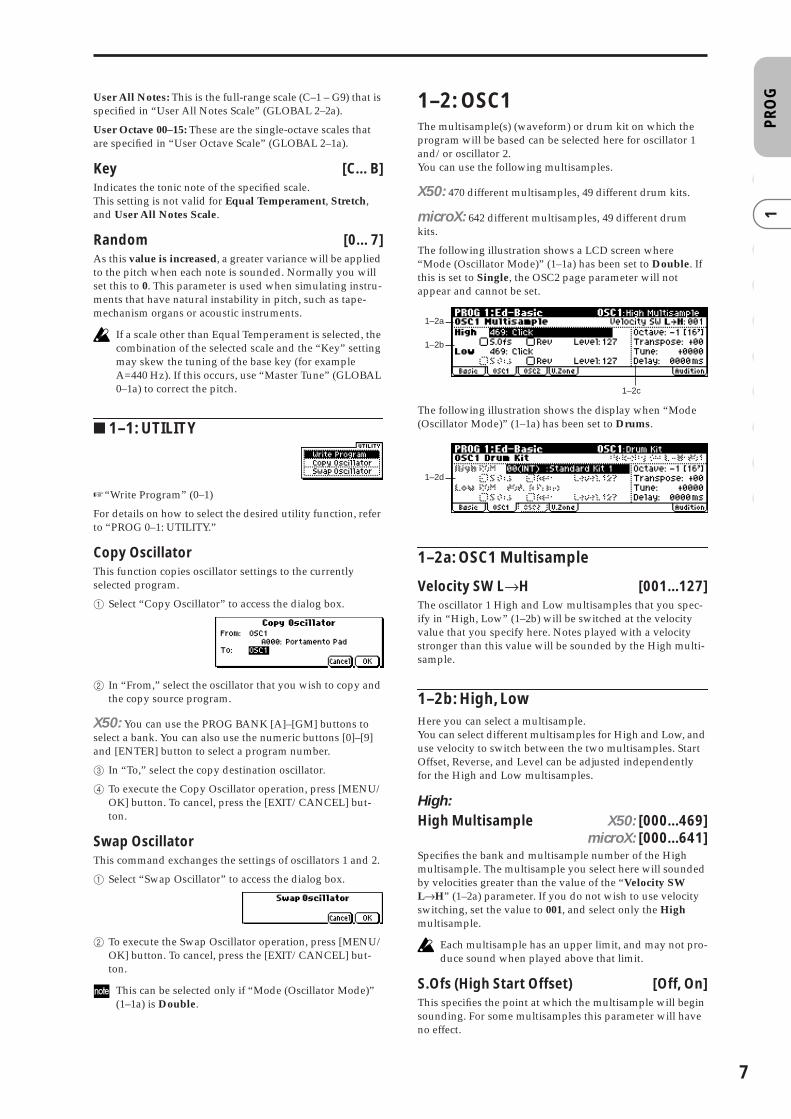
The following illustration shows a LCD screen where “Mode (Oscillator Mode)” (1–1a) has been set to Double. If this is set to Single, the OSC2 page parameter will not appear and cannot be set.
The following illustration shows the display when “Mode (Oscillator Mode)” (1–1a) has been set to Drums.
1–2a: OSC1 Multisample
Velocity SW L→H [001...127]The oscillator 1 High and Low multisamples that you spec-ify in “High, Low” (1–2b) will be switched at the velocity value that you specify here. Notes played with a velocity stronger than this value will be sounded by the High multi-sample.
1–2b: High, LowHere you can select a multisample.You can select different multisamples for High and Low, and use velocity to switch between the two multisamples. Start Offset, Reverse, and Level can be adjusted independently for the High and Low multisamples.
High:High Multisample X50: [000...469]
microX: [000...641]Specifies the bank and multisample number of the High multisample. The multisample you select here will sounded by velocities greater than the value of the “Velocity SW L→H” (1–2a) parameter. If you do not wish to use velocity switching, set the value to 001, and select only the High multisample.
Each multisample has an upper limit, and may not pro-duce sound when played above that limit.
S.Ofs (High Start Offset) [Off, On]This specifies the point at which the multisample will begin sounding. For some multisamples this parameter will have no effect.
1–2a
1–2b
1–2c
1–2d
7

8
On (checked): The sound will start from the start offset loca-tion that is pre-determined for each multisample.Off (unchecked): The sound will start from the beginning of the multisample waveform.
Rev (High Reverse) [Off, On]The multisample will be played in reverse. If the multisam-ple was originally set to reverse, it will playback without change.
On (checked): The multisample will playback in reverse.Off (unchecked): The multisample will playback normally.
Level (High Level) [000...127]Specifies the level of the multisample.
Depending on the multisample, high settings of this parameter may cause the sound to distort when a chord is played. If this occurs, lower the level.
Low:Specifies the OSC1 Low multisample.The Low multisample will sound when the velocity is less than the “Velocity SW L→H” (1–2a) setting.
Low Multisample X50: [000...469]microX: [000...641]
S.Ofs (Low Start Offset) [Off, On]Rev (Low Reverse) [Off, On]Level (Low Level) [000...127]☞Refer to the corresponding item in “High.”
1–2c: Octave, Transpose, Tune, Delay
Octave [–2[32’], –1[16’], +0[8’], +1[4’]]Adjusts the pitch in octave units. The normal octave of the multisample is 8' (feet).
Transpose [–12…+12]Adjusts the pitch in semitone steps over a range of ±1 octave.
Tune [–1200…+1200]Adjusts the pitch of the sample in one-cent steps (a semitone is 100 cents) over a range of ±1 octave.
Delay [0000ms…5000ms, KeyOff]Specifies a delay time from note-on until the note will sound.With a setting of KeyOff, the sound will begin when note-off occurs. This is used to create sounds such as the “click” that is heard when a harpsichord note is released. In this case, set the “Amp1 EG”, “Amp2 EG” (6–3, 6–6) “S (Sustain Level)” parameter to 0.
1–2d: OSC1 Drum Kit
Drum KitX50: [00(INT)...15(INT), 16(User)...39(User), 40(GM)...48(GM)]
microX: [00(INT)...31(INT), 32(User)...39(User), 40(GM)...48(GM)]Select a drum kit.
X50
microX
Octave [–2[32’], –1[16’], +0[8’], +1[4’]]Adjusts the pitch in octave units. When using a drum kit, set the Octave to +8'.
When editing a drum program, you must set this parameter to +8'. With other settings, the sounds of the drum kit will be assigned to the wrong notes of the key-board.
Transpose [–12…+12]This adjusts the location of the instruments in the selected drum kit. Unless you need to change this, leave it at 0.
Tune [–1200…+1200]This adjusts the pitch in one-cent units.The pitch of each drum kit can be adjusted in GLOBAL 4: DKit.
Delay [0000ms…5000ms, KeyOff]This specifies a delay time from note-on until the sound will begin.With a setting of KeyOff, the sound will begin when note-off occurs. In this case, set the “Amp1 EG” parameter “S (Sustain Level)” (6–3a) to 0.
■ 1–2: UTILITY
☞“Write Program” (0–1), “Copy Oscillator,” “Swap Oscilla-tor” (1–1)
For details on how to select the desired utility function, refer to “PROG 0–1: UTILITY.”
00 (INT)–15 (INT) Preload drum kits.
16 (User)–39 (User) for user drum kits
40 (GM)–48 (GM) ROM preset drum kits compatible with GM2.
00 (INT)–31 (INT) Preload drum kits.
32 (User)–39 (User) for user drum kits
40 (GM)–48 (GM) ROM preset drum kits compatible with GM2.

PR
OG
0 1
23
45
67
89
Select by CategorySelects multisamples by category.For the procedure, refer to “Select by Category” (☞p.2).
This command is valid if “Mode (Oscillator Mode)” (1–1a) is set to Single or Double, and you have selected the 1–2b: High, Low parameter.
1–3: OSC2This will appear when “Mode (Oscillator Mode)” (1–1a) is set to Double.For details on the settings and function of the parameter, refer to “1–2: OSC1.”
1–4: V.Zone (Velocity Zone)
Specifies the range of velocities that will sound oscillator 1 and 2. By using these settings in conjunction with the “Velocity SW L→H” (1–2a) setting of each oscillator, you can specify the velocity ranges for the High and Low multisam-ples or drum kits.
1–4a: OSC 1/2 Velocity Zone
OSC1 Bottom [001...127]Sets the minimum velocity value that will sound oscillator 1.
OSC1 Top [001...127]Sets the maximum velocity value that will sound oscillator 1.
OSC2 Bottom [001...127]Sets the minimum velocity value that will sound oscillator 2.
OSC2 Top [001...127]Sets the maximum velocity value that will sound oscillator 2.
It is not possible to set the Bottom Velocity greater than the Top Velocity, nor the Top Velocity less than the Bot-tom Velocity.
X50: You can also input a value by playing a note on the keyboard while you hold down the [ENTER] button.
■ 1–4: UTILITY☞“Write Program” (0–1), “Copy Oscillator,” “Swap Oscilla-
tor” (1–1)
1–5: AuditionWhen selecting preloaded programs, you can play back a pre-specified riff (phrase) that is suitable for the sound of that program. This is called the Audition function.When you press the [AUDITION] button to turn it on, the audition riff will play back repeatedly.
Here you can select the audition riff and specify the transpo-sition.
1–5a: Audition Riff, Transpose
Audition Riff [000: Off...383: name]Selects the audition riff. The X50/microX contains 383 audi-tion riffs suitable for a variety of instruments and musical genres.With a setting of 000: Off, no riff will be played.
Transpose [–24...+24]Adjusts the pitch of the audition riff in semitone steps.
It is not possible to change the playback tempo of the audition riff. Nor is it possible to set the arpeggiator tempo while the audition riff is playing.
The arpeggiator will be turned off while the audition riff is playing.
■ 1–5: UTILITY☞“Write Program” (0–1)
1–4a
1–5a
9

10
PROG 2: Ed–Pitch
Here you can make pitch modulation settings for oscillators 1 and 2.
2–1: OSC1Specifies how the key position (on the keyboard) will affect the pitch of oscillator 1, and selects the controller that will modify the pitch and the depth of this effect. Here you can also specify the amount of pitch change caused by the pitch EG, and set the portamento mode and on/off status.
X50
microX
2–1a: Pitch
Pitch Slope [–1.0…+2.0]Normally you will leave this at +1.0.Positive (+) values will cause the pitch to rise as you play higher on the keyboard, and negative (–) values will cause the pitch to fall as you play higher on the keyboard.With a value of 0, there will be no change in pitch, and the C4 pitch will sound regardless of the keyboard location you play.
How the Pitch Slope and pitch are related
Ribbon (#16) [–12…+12]Specifies in semitone units how the pitch will change when CC#16 is received (or when the ribbon controller is pressed on an instrument, such as the TRITON Extreme, connected via the MIDI IN connector).
12 half-steps equal one octave. With positive (+) values, the pitch will rise when you press the right half of a ribbon con-troller. With negative (–) values, the pitch will fall.
For example, with a setting of +12, pressing the far right edge of the ribbon controller will raise the pitch one octave. With a setting of –12, pressing the far right edge of the rib-bon controller will lower the pitch one octave.
At the center of the ribbon controller, the original pitch will remain, so you can use this in conjunction with pressing the ribbon at its right edge to simulate the “hammering-on” techniques used by guitarists.
X50: PBend + [–60…+12]Specifies the amount of pitch change (in semitones) that will occur when you move the [PITCH] wheel up from the center position.
For example if this is set to +12, moving the [PITCH] wheel up from the center position will raise the pitch by one octave.
microX: JS (+X) [–60…+12]Specifies how the pitch will change when the joystick is moved all the way to the right. A setting of 12 produces 1 octave of change.
For example, if you set this to +12 and move the joystick all the way to the right, the pitch will rise one octave above the original pitch.
X50: PBend – [–60…+12]Specifies the amount of pitch change (in semitones) that will occur when you move the [PITCH] wheel down from the center position.
For example if this is set to +12, moving the [PITCH] wheel down from the center position will raise the pitch by one octave.
microX: JS (–X) [–60…+12]Specifies how the pitch will change when the joystick is moved all the way to the left.A setting of 12 produces 1 octave of change.
For example, if you set this to –60 and move the joystick all the way to the left, the pitch will fall five octaves below the original pitch. This can be used to simulate the downward swoops that a guitarist produces using the tremolo arm.
AMS (Pitch AMS) [Off, (FEG, AEG, EXT)]Selects the source that will modulate the pitch of oscillator 1 (☞p.152 “AMS List”).
Intensity (AMS Intensity) [–12.00…+12.00]Specifies the depth and direction of the effect produced by “AMS (Pitch AMS).”With a setting of 0, no modulation will be applied. With a setting of 12.00, the pitch will change up to one octave.
For example if “AMS (Pitch AMS)” is set to Pedal #04, Glo-bal 0–3a “Foot Pedal Assign” is set to Foot Pedal (CC#04), and you advance a foot pedal connected to the ASSIGN-ABLE PEDAL jack, the pitch will rise if you have assigned a positive (+) value here, or fall if you have assigned a nega-tive (–) value. The maximum range is one octave. (☞p.154)
2–1b: Pitch EG
Intensity [–12.00…+12.00]Specifies the depth and direction of the modulation that the pitch EG specified in “EG (Pitch EG)” (2–5) page will apply to the pitch.With a setting of 12.00, the pitch will change a maximum of ±1 octave.
2–1a
2–1b
2–1c
2–1a
2–1b
2–1c
Pitch
Key
2oct1oct1oct
C4 C5
+2
+1
0
–1

PR
OG
0 1
23
45
67
89
AMS (Pitch EG AMS) [Off, (KT, EXT)]Selects the source that will control the pitch modulation applied by the pitch EG (☞p.152 “AMS List”).
Intensity (AMS Intensity) [–12.00…+12.00]Specifies the depth and direction of the effect that “AMS (Pitch EG AMS)” will have.
For example, if you set “AMS (Pitch EG AMS)” to Velocity and set this value to +12.00, the velocity will control the range of pitch change produced by the pitch EG in a range of ±1 octave (☞p.154). As you play more softly, the pitch change will draw closer to the pitch EG levels.
“Intensity” and “AMS (Pitch EG AMS)” will be summed to determine the depth and direction of the pitch modulation applied by the pitch EG.
2–1c: PortamentoThis turns the portamento effect (smooth change in pitch from one note to the next) on/off, and specifies how it will be applied.If you set Global 0–3a “Foot SW Assign” to Portamento SW (CC#65) and turn a pedal switch connected to the ASSIGN-ABLE SWITCH jack on/off, the portamento effect will be applied according to these settings.(☞p.164 “Foot Switch Assign List” Portamento SW (CC#65))
X50: If [SW1] or [SW2] is set to Porta.SW (CC#65), using SW1 or SW2 to turn portamento on/off will apply the set-tings you specify here.(☞p.152 “AMS List,” ☞p.161 “SW1, SW2 Assign List” Prta. SWCC#65)
Portamento will also be switched when CC#65 (Porta-mento SW) is received.
Enable (Porta. Enable) [Off, On]On (checked): Portamento will be applied.Off (unchecked): Portamento will not be applied.
Fingered (Porta. Fingered) [Off, On]This parameter is available when “Enable (Porta. Enable)” is checked.
On (checked): Portamento will be applied when you con-tinue holding the previous note as you press the next note (legato playing).Off (unchecked): Portamento will always be applied, regardless of how you play.
Time (Porta. Time) [000...127]This parameter is available when “Enable (Porta. Enable)” is checked.This sets the portamento time. Increasing the value will pro-duce a slower change in pitch.
■ 2–1: UTILITY☞“Write Program” (0–1), “Copy Oscillator,” “Swap Oscilla-
tor” (1–1)
2–2: OS1lfo (OSC1 LFO)
Specifies the amount of pitch change produced by LFO1 and LFO2 for oscillator 1.
X50
microX
2–2a: Pitch LFO1/2 Modulation
LFO1:
Intensity (LFO1 Intensity) [–12.00…+12.00]Specifies the depth and direction of the pitch modulation applied by the OSC 1 LFO1 settings you made in “OS1LFO1” page (3–1).With a setting of 12.00, a maximum of ±1 octave of pitch modulation will be applied. Negative (–) values will invert the LFO waveform.
X50: Mod.Whl Int. (LFO1 Mod.Whl+Int.)[–12.00…+12.00]
Specifies the depth of pitch modulation that will be applied by OSC1 LFO1 when you move the [MOD] up.As you specify a higher value for this parameter, a greater amount of pitch modulation will be applied by OSC1 LFO1 when you move the [MOD] wheel up (away from yourself). With a setting of 12.00, a maximum of ±1 octave of pitch modulation will be applied. Negative (–) values will invert the polarity of the LFO.
microX: JS+Y Int. (LFO1 JS+Y Int.)[–12.00…+12.00]
Specifies the depth and direction of the effect that joystick movement in the +Y direction (up) will have on the pitch modulation applied by the OSC1 LFO1.As this value is increased, moving the joystick in the +Y direction will cause the OSC1 LFO1 to produce deeper pitch modulation. With a setting of 12.00 a maximum of ±1 octave of pitch modulation will be applied. Negative (–) values will invert the LFO waveform.
AMS (LFO1 AMS)[Off, (PEG, FEG, AEG, KT, EXT)]
Indicates the source that will control the depth of pitch mod-ulation produced by the OSC1 LFO1 (☞p.152 “AMS List”).
Pitch change (level)
Softly played(Intensity (Pitch EG) setting)
Strongly played with anegative (–) value
Strongly played witha positive (+) value
Note-onNote-off
Note-onNote-off
Note-onNote-off
2–2a
2–2a
11

12
Intensity (AMS Intensity) [–12.00…+12.00]Specifies the depth and direction of the effect that “AMS (LFO1 AMS)” will have.With a setting of 0, modulation will not be applied. With a setting of 12.00, the OSC1 LFO1 will apply a maximum of ±1 octave of pitch modulation. Negative (–) settings will invert the LFO waveform.
For example if “AMS (LFO1 AMS)” is set to Pedal #04, Glo-bal 0–3a “Foot Pedal Assign” is set to Foot Pedal (CC#04), and you advance a foot pedal connected to the ASSIGN-ABLE PEDAL jack, the pitch modulation produced by OSC1 LFO1 will be applied in the normal phase if you have assigned a positive (+) value, or in the reverse phase if you have assigned a negative (–) value.
The depth and direction of the pitch modulation pro-duced by OSC1 LFO1 depends on the sum of the settings for “Intensity (LFO1 Intensity),” X50: “M.Whl+Int.” (LFO1 MWheel+Int.)”/microX: “JS+Y Int. (LFO1 JS+Y Int.),” and “AMS (LFO1 AMS). (☞p.154)
LFO2:
Intensity (LFO2 Intensity) [–12.00…+12.00]X50: Mod.Whl Int. (LFO2 Mod.Whl Int.)
[–12.00…+12.00]microX: JS+Y Int. (LFO2 JS+Y Int.)
[–12.00…+12.00]AMS (LFO2 AMS)
[Off, (PEG, FEG, AEG, KT, EXT)]Intensity (AMS Intensity) [–12.00…+12.00]Refer to the preceding section “LFO1.”
■ 2–2: UTILITY☞“Write Program” (0–1), “Copy Oscillator,” “Swap Oscilla-
tor” (1–1)
2–3: OSC2Specifies how the key position (on the keyboard) will affect the pitch of oscillator 2, and selects the controller that will affect the pitch and specify the depth of control. Here you can also specify the amount of pitch change produced by the pitch EG, and set the portamento mode and on/off status. For details on each parameter, refer to the preceding “2–1: OSC1.”
2–4: OS2lfo (OSC2 LFO)
Specifies the amount of pitch change produced by LFO1 and LFO2 for oscillator 2. For an explanation of each parameter, refer to the preceding “2–2: OS1lfo.”
2–5: EG (Pitch EG)
Here you can make settings for the pitch EG, which creates time-variant changes in the pitch of oscillators 1 and 2.The depth of pitch change produced by these EG settings on oscillator 1 (2) is adjusted by “Pitch EG” (2–1b, 2–3).
2–5a: Pitch EGThese settings specify how the pitch will change over time.
L (Level parameters):These parameters specify the amount of pitch change.The actual amount of pitch change will depend on the “Pitch EG” (2–1b, 2–3) parameter “Intensity.”
For example with an “Intensity” setting of +12.00, a “Level” setting of +99 would raise the pitch one octave, and a “Level” setting of –99 would lower the pitch one octave.
S (Start Level) [–99…+99]Specifies the amount of pitch change at note-on.
A (Attack Level) [–99…+99]Specifies the amount of pitch change when the attack time has elapsed.
R (Release Level) [–99…+99]Specifies the amount of pitch change when the release time has elapsed.
T (Time parameters):These parameters specify the length of time over which the pitch change will occur.
A (Attack Time) [0…99]Specifies the time over which the pitch will change from note-on until it reaches the pitch specified as the attack level.
D (Decay Time) [0…99]Specifies the time over which the pitch will change after reaching the attack level until it reaches the normal pitch.
R (Release Time) [0…99]Specifies the time over which the pitch will change from note-off until it reaches the pitch specified as the release level.
2–5a
2–5b
2–5c
Note-on Note-off
AttackTime
DecayTime
Start Level Release Level
Release Time
Attack Level+99 = approximately 1 octave
–99 = approximately 1 octave
0 = pitch whenkey is held(sustained)
Time
Time-varying pitch settings (when Pitch EG Intensity = +12.00)

PR
OG
0 1
23
45
67
89
2–5b: Level Mod. (Level Modulation)These settings allow the pitch EG “L (Level parameters)” to be controlled by alternate modulation.
AMS1 (Level Mod. AMS1) [Off, (KT, EXT)]Selects the source that will control the pitch EG “L (Level parameters)” (☞p.152 “AMS List”).
I (AMS1 Intensity) [–99…+99]Specifies the depth and direction of the effect applied by “AMS1 (Level Mod. AMS1).”With a setting of 0, the levels specified by “Pitch EG” (2–5a) will be used.If “AMS1” is set to Velocity, increasing the absolute value of “Intensity” will produce increasingly wider change in pitch EG levels for strongly-played notes. The direction of the change is specified by “S (AMS1 SW Start)” and “A (AMS1 SW Attack).” As you play more softly, the pitch change will draw closer to the pitch EG levels.
X50: For example if “AMS1 (Level Mod. AMS1)” is set to SW1 #80 and 7–3b: SW1/2 Assign “SW1” is set to SW1 Mod. (CC#80), turning [SW1] on will change the Pitch EG “Level.” Increasing the absolute value of “I (AMS1 Intensity)” will produce a greater change in the pitch EG level when [SW1] is turned on. The direction of the change is specified by “S (AMS1 SW Start)” and “A (AMS1 SW Attack).” If [SW1] is off, the levels specified by the pitch EG settings will be used.
microX: For example if “AMS1 (Level Mod. AMS1)” is set to FootSW #82 and Global 0–3a “Foot SW Assign” is set to Foot SW (CC#82), receiving CC#82 or turning on the pedal switch will change the Pitch EG “Level.” Increasing the absolute value of “I (AMS1 Intensity)” will produce a greater change in the pitch EG level when the pedal switch is turned on. The direction of the change is specified by “S (AMS1 SW Start)” and “A (AMS1 SW Attack).” If the pedal switch is off, the levels specified by the pitch EG settings will be used.
S (AMS1 SW Start) [–, 0, +]Specifies the direction of change in “S (Start Level)” caused by “AMS1 (Level Mod. AMS1).” If “I (AMS1 Intensity)” is a positive (+) value, a setting of + will raise the EG level, and a setting of – will decrease it. With a setting of 0 there will be no change.
A (AMS1 SW Attack) [–, 0, +]Specifies the direction of change in “A (Attack Level)” caused by “AMS1 (Level Mod. AMS1).” If “I (AMS1 Inten-sity)” is a positive (+) value, a setting of + will raise the EG level, and a setting of – will decrease it. With a setting of 0 there will be no change.
AMS2 (Level Mod. AMS2) [Off, (KT, EXT)]I (AMS2 Intensity) [–99…+99]S (AMS2 SW Start) [–, 0, +]A (AMS2 SW Attack) [–, 0, +]Refer to the preceding paragraphs “AMS1 (Level Mod. AMS1)”–“A (AMS1 SW Attack).”
2–5c: Time Mod. (Time Modulation)These parameters let you use alternate modulation to con-trol the “T (Time parameters)” of the pitch EG.
AMS (Time Mod. AMS) [Off, (KT, EXT)]Indicates the source that will control the “T (Time parame-ters)” of the pitch EG (☞p.152 “AMS List”).
I (AMS Intensity) [–99…+99]Specifies the depth and direction of the effect that “AMS (Time Mod. AMS)” will have.With a setting of 0, the pitch EG times will be just as speci-fied by the “Pitch EG” (2–5a) settings.The alternate modulation value at the moment that the EG reaches each point will determine the actual value of the EG time that comes next.
For example, the decay time will be determined by the alter-nate modulation value at the moment that the attack level is reached.When this parameter is set to values of 16, 33, 49, 66, 82, or 99, the specified EG times will speed up as much as 2, 4, 8, 16, 32, or 64 times respectively (or slowed down to 1/2, 1/4, 1/8, 1/16, 1/32, or 1/64 of the original time).
For example if “AMS (Time Mod. AMS)” is set to Velocity, increasing the absolute value of “I (AMS Intensity)” will allow strongly-played notes to increase the changes in pitch EG “T (Time parameters)” values. The direction of the change is specified by “A (AMS SW Attack)” and “D (AMS SW Decay).” As you play more softly, the pitch EG times will more closely approach the actual settings of the pitch EG.
A (AMS SW Attack) [–, 0, +]Specifies the direction in which “AMS (Time Mod. AMS)” will affect the “A (Attack Time).” With positive (+) values of “I (AMS Intensity),” a setting of + will cause the time to be lengthened, and a setting of – will cause the time to be short-ened. With a setting of 0 there will be no change.
D (AMS SW Decay) [–, 0, +]Specifies the direction in which “AMS (Time Mod. AMS)” will affect the “D (Decay Time).” With positive (+) values of “I (AMS Intensity),” a setting of + will cause the time to be lengthened, and a setting of – will cause the time to be short-ened. With a setting of 0 there will be no change.
■ 2–5: UTILITY☞“Write Program” (0–1), “Copy Oscillator,” “Swap Oscilla-
tor” (1–1)
Pitch EG change (level) (AMS=SW1/Velocity, Intensity= positive (+) value)
Note-onNote-off
Note-onNote-off
Note-onNote-off
A note played softly with “S” set at 0, “A” set to +, and SW1 turned off (the settings of 2–5a: Pitch EG)
A note played strongly with “S” set to 0, “A” set to +, and SW1 turned on
A note played strongly with “S” set to 0, “A” set to –, and SW1 turned on
Pitch EG changes (Time) (AMS = Velocity, Intensity = positive (+) value)
Note-onNote-off
Note-onNote-off
Note-onNote-off
A note played softly with “A” set to + and “D” set to + (settings of 2–5a: Pitch EG)
A note played strongly with “A” set to + and “D” set to +
A note played strongly with “A” set to – and “D” set to –
13

14
PROG 3: Ed–LFOs
Here you can make settings for the LFO that can be used to cyclically modulate the Pitch, Filter, and Amp of oscillators 1 and 2. There are two LFO units for each oscillator.By setting the LFO1 or LFO2 Intensity to a negative (–) value for Pitch, Filter, or Amp, you can invert the LFO waveform.
3–1: OS1LFO1 (OSC1 LFO1)
Indicates settings for the “OSC1 LFO1,” which is the first LFO that can be used for oscillator 1.
3–1a: OSC1 LFO1
Waveform [Triangle 0…Random6 (Vect.)]Selects the LFO waveform.
The numbers that appear at the right of some of the LFO waveforms indicate the phase at which the waveform will begin.
Frequency [00…99]Sets the LFO frequency. A setting of 99 is the fastest.
Ofs (Offset) [–99…+99]Specifies the central value of the LFO waveform.
For example, with a setting of 0 as shown in the following diagram, the vibrato that is applied will be centered on the note-on pitch. With a setting of +99, the vibrato will only raise the pitch above the note-on pitch, in the way in which vibrato is applied on a guitar.
Offset settings and pitch change produced by vibrato
When “Waveform” is set to Guitar, the modulation will occur only in the positive (+) direction even if you set “Off-set” to 0.
Key Sync. [Off, On]On (checked): Key Sync. will be On. The LFO will start each time you play a note, and an independent LFO will operate for each note.Off (unchecked): Key Sync. will be Off, and the LFO effect that was started by the first-played note will continue to be applied to each newly-played note. (In this case, “Delay” and “Fade” will be applied only to the LFO when it is first started.)
Fade [00…99]Specifies the time from when the LFO begins to apply until it reaches the maximum amplitude. When “Key Sync.” is Off, the fade will apply only when the LFO is first started.
How “Fade” affects the LFO (when “Key Sync.” is On)
Dly (Delay) [00…99]Specifies the time from note-on until the LFO effect begins to apply.When “Key Sync.” is Off, the delay will apply only when the LFO is first started.
3–1b: Freq.Mod (Frequency Modulation)You can use two alternate modulation sources to adjust the speed of the OSC1 LFO1.
AMS1 (Freq. AMS1)[Off, (PEG, FEG, AEG, LFO2, KT, EXT)]
Indicates the source that will adjust the frequency of the oscillator 1 LFO1 (☞p.152 “AMS List”). OSC1 LFO1 can be modulated by OSC1 LFO2.
Int (AMS1 Intensity) [–99…+99]Specifies the depth and direction of the effect that “AMS1 (Freq. AMS1)” will have.When this parameter is set to a value of 16, 33, 49, 66, 82, or 99, the LFO frequency being can be increased by a maxi-mum of 2, 4, 8, 16, 32, or 64 times respectively (or decreased by 1/2, 1/4, 1/8, 1/16, 1/32, or 1/64 respectively).
For example, if “AMS1 (Freq. AMS1)” is Note No., positive (+) values of this parameter will cause the oscillator 1 LFO to speed up as you play higher notes. Negative (–) values will cause the oscillator 1 LFO to slow down as you play higher notes. This change will be centered on the C4 note.
X50: If “AMS1 (Freq. AMS1)” is set to Mod.Whl#01, speci-fying a higher value for this parameter will let you increase the OSC1 LFO speed more greatly by moving the [MOD] wheel. With a setting of +99, moving the [MOD] wheel all the way up will increase the LFO speed by approximately 64 times.
microX: If “AMS1 (Freq. AMS1)” is set to JS +Y #01, rais-ing the value of this parameter will cause the oscillator 1 LFO1 speed to increase as the joystick is moved up. With a setting of +99, moving the joystick all the way up will increase the LFO speed by approximately 64 times.
3–1a
3–1b
3–1c
Triangle wave
Phase will changerandomly at each key-in
Sawtooth down ↓
Square wave
Sine wave
Guitar vibrato
Triangle 0
Triangle 90
TriangleRandom
Saw 0
Saw 180
Square
Sine
Guitar
Exp.Triangle
Exp.Saw Down
Exp.Saw Up
Step Triangle – 4
Step Triangle – 6
Step Saw – 4
Step Saw – 6
Random1 (S/H):Conventional sample & hold (S/H) in which the level changes randomly at fixed intervals of timeRandom2 (S/H):Both the levels and the time intervals will change randomly.Random3 (S/H):The maximum level and minimum level will alternate at random intervals of time (i.e., a square wave with random period).
Random4 (Vect.)Random5 (Vect.)Random6 (Vect.)These types cause Random 1–3 to change smoothly. They can be used to simulate the instability of acoustic instruments etc.
offset = –99 offset = 0 offset = +99Pitch
Pitch at note-on
Note-on Note-off“Fade”
“Delay”

PR
OG
0 1
23
45
67
89
AMS2 (Freq. AMS2)[Off, (PEG, FEG, AEG, LFO2, KT, EXT)]
Int (AMS2 Intensity) [–99…+99]Indicates settings for a second alternate modulation source that will adjust the frequency of the oscillator 1 LFO1.
☞“AMS1 (Freq. AMS1),” “Int. (AMS1 Intensity)”
3–1c: MIDI/Tempo Sync. (Frequency MIDI/Tempo Sync.)
Sync. (MIDI/Tempo Sync.) [Off, On]On (checked): The LFO frequency will synchronize to the tempo (MIDI Clock). In this case, the values you specified for “Frequency” (3–1a) and “Freq.Mod” (3–1b) will be ignored.
Base Note (Sync. Base Note)[ � , � � , � , � � , � , � � , � , � ]
Times (Sync. Times) [01...16]When “Sync. (MIDI/Tempo Sync.).” is checked, these When “Sync. (MIDI/Tempo Sync.)” is checked, these parameters specify a note length “Base Note (Sync. Base Note)” relative to “� (Tempo)” and the multiple “Times (Sync. Times)” that will be applied to it. These parameters will determine the frequency of the OSC1 LFO1.
For example if “Base Note (Sync. Base Note)” is � (quarter note) and “Times (Sync. Times)” is 04, the LFO will perform one cycle every four beats.Even if you change the “� (Tempo)” setting of the arpeggiator, the LFO will always complete one cycle every four beats.
■ 3–1: UTILITY
☞“Write Program” (0–1)
For details on how to select the desired utility function, refer to “PROG 0–1: UTILITY.”
Swap LFO 1&2This exchanges the settings of LFO 1 and 2. If LFO2 is selected in AMS1 (Freq. AMS1) or AMS2 (Freq. AMS2) of LFO1 Freq.Mod (3–1b), then these settings will be invalid for LFO2 after LFO1 and 2 have been exchanged. If you select this from the OSC1 LFO1 or OSC1 LFO2 page, LFO1 and LFO2 of OSC1 will be exchanged.
1 Select “Swap LFO 1&2” to access the dialog box.
2 To execute, press the [MENU/OK] button. To cancel without executing, press the [EXIT/CANCEL] button.
3–2: 1 LFO2 (OSC1 LFO2)
Here you can make settings for the OSC1 LFO2, which is the second LFO that can be applied to oscillator 1. (☞“3–1: OS1LFO1 (OSC1 LFO1)”) However, it is not possible to use the LFO to apply modulation in “AMS1 (Freq. AMS1)” or “AMS2 (Freq. AMS2)” of Freq. Mod.
3–3: 2 LFO1 (OSC2 LFO1)
This can be used when “Mode (Oscillator Mode)” (1–1a) is set to Double. Here you can make settings for the OSC2 LFO1, which is the first LFO that can be applied to oscillator 2 (☞“3–1: OS1LFO1 (OSC1 LFO1)”).
3–4: 2 LFO2 (OSC2 LFO2)
This can be used when “Mode (Oscillator Mode)” (1–1a) is set to Double. Here you can make settings for the OSC2 LFO2, which is the second LFO that can be applied to oscil-lator 2 (☞“3–1: OS1LFO1 (OSC1 LFO1)” and “3–2: 1 LFO2 (OSC1 LFO2)”).
15

16
PROG 4: Ed–Filter1
Indicates settings for filter 1, which controls the tone of oscil-lator 1. You can select either a 24 dB/oct low pass filter with resonance, or a 12 dB/oct low pass filter and 12 dB/oct high pass filter connected in series.When “Mode (Oscillator Mode)” (1–1a) is Single, Drums you can use filter 1. When it is Double, you can use filters 1 and 2. In the case of Single and Drums, the filter 2 pages cannot be selected.
4–1: BasicHere you can specify the basic filter type used by oscillator 1, and set the cutoff frequency and resonance.
4–1a: Filter1
Type (Filter1 Type)[Low Pass Resonance, Low Pass & High Pass]
Indicates the type of filter 1.
Trim [00…99]Adjusts the level at which the audio signal output from OSC1 is input to filter 1A.
If the trim value is set too high, the sound may be dis-torted if the Resonance is set to a high value or when you play a chord.
4–1b: A (Filter A)This filter cuts the high-frequency range above the cutoff fre-quency. This is the most common type of filter, which cuts the overtone structure to make a bright (sharp) tone darker (mellow).When “Type (Filter1 Type)” is Low Pass Resonance, the cut will have a steeper curve.
Frequency (A Frequency) [00…99]Specifies the cutoff frequency of filter 1A.
Resonance (A Resonance) [00…99]This emphasizes the overtone components that lie in the region of the cutoff frequency specified by “Frequency (A Frequency),” producing a more distinctive sound. Increas-ing this value will produce a stronger effect.
Reso.AMS (Resonance AMS)[Off, (PEG, FEG, AEG, LFO, KT, EXT)]
Indicates the source that will control the “Resonance (A Res-onance)” level (☞p.152 “AMS List”).
Intensity (AMS Intensity) [–99…+99]Specifies the depth and direction of the effect that “Reso. AMS (Resonance AMS)” will have on the resonance level specified by “Resonance (A Resonance).”The resonance level is determined by adding the “Reso-nance (A Resonance)” and “Intensity (AMS Intensity)” val-ues together.
For example, if Velocity has been selected, changes in key-board velocity will affect the resonance.With positive (+) values, the resonance will increase as you play more strongly, and as you play more softly the reso-nance will approach the level specified by the “Resonance (A Resonance)” setting.With negative (–) values, the resonance will decrease as you play more strongly, and as you play more softly the reso-nance will approach the level specified by the “Resonance (A Resonance)” setting.
4–1c: B (Filter B)This will be displayed if “Type (Filter1 Type)” (4–1a) is Low Pass & High Pass.This filter cuts the low-frequency range that lies below the cutoff frequency.By cutting the lower overtones, it lightens the tone.
Frequency (B Frequency) [00…99]Specifies the cutoff frequency of filter 1B.
■ 4–1: UTILITY☞“Write Program” (0–1), “Copy Oscillator,” “Swap Oscilla-
tor” (1–1)
4–1a
4–1b
4–1c
Low Pass Resonance: 24 dB/octave low pass filter with resonance
Low Pass & High Pass: 12 dB/octave low pass filter and 12 dB/octave high pass filter in series
Frequency
Level
Low Pass
12dB/oct
24dB/oct
The effect of resonance
Low PassLevel
Low resonance value High resonance value
Level
Frequency
High Pass
12dB/oct

PR
OG
0 1
23
45
67
89
4–2: Mod.1 (Filter1 Modulation1)
Indicates settings for keyboard tracking which modifies the tone by modulating the filter 1 cutoff frequency “Frequency (A/B Frequency),” and intensity settings for the filter 1 EG, etc.
4–2a: Keyboard Track These settings specify keyboard tracking for the cutoff fre-quency of filter 1. The way in which the cutoff frequency is affected by the position of the key (on the keyboard) that you play can be specified by the Key: “Low” and “High,” Ramp: “Low” and “High” parameters.
Key:Specifies the note numbers at which keyboard tracking will begin to be applied, and set the “Int. to A” and “(Int. to) B” parameters to specify the depth and direction of the change applied to filter 1 A and B.For the range of notes between “Low (KBDTrk Key Low)” and “High (KBDTrk Key High),” the cutoff frequency will change according to the key location (pitch).
X50: You can also input a value by playing a note on the keyboard while you hold down the [ENTER] button.
Low (KBDTrk Key Low) [C–1…G9]Keyboard tracking will apply to the range below the speci-fied note number.
High (KBDTrk Key High) [C–1…G9]Keyboard tracking will apply to the range above the speci-fied note number.
Ramp (Ramp Setting):Specifies the angle of keyboard tracking.
Low (KBDTrk Ramp Low) [–99…+99]High (KBDTrk Ramp High) [–99…+99]If “Int. to A (KBDTrk Int. to A)” and “Int. to B (KBDTrk Int. to B)” are set to +50, “Low (KBDTrk Ramp Low)” is set to–62 and “High (KBDTrk Ramp High)” is set to +62, the angle of the change in cutoff frequency will correspond to the key location (pitch). This means that the oscillation that occurs when you increase the “Resonance (A Resonance)” (4–1b) will correspond to the keyboard location.If you set “Low (KBDTrk Ramp Low)” to +43 and “High (KBDTrk Ramp High)” to –43, the cutoff frequency will not be affected by keyboard location. Use this setting when you do not want the cutoff frequency to change for each note.
How cutoff frequency is affected by keyboard location and the Ramp setting (“Int. to A,” “Int. to B”=+50)
Int. to A (KBDTrk Int. to A) [–99...+99]Specifies the depth and direction of the effect on filter 1A produced by keyboard tracking settings “Low (KBDTrk Key Low),” “High (KBDTrk Key High),” “Low (KBDTrk Ramp Low),” and “High (KBDTrk Ramp High).”With positive (+) settings, the effect will be in the same direction as the keyboard tracking settings.With negative (–) settings, the effect will be in the opposite direction.
Int. to B (KBDTrk Int. to B) [–99...+99]Specifies the depth and direction of the effect on filter 1B produced by keyboard tracking. (☞“Int. to A (KBDTrk Int. to A)”)
4–2b: Filter EG
Int. to A (Intensity to A) [–99…+99]Specifies the depth and direction of the effect that the time-varying changes created by the filter 1 EG will have on the filter 1A cutoff frequency.With positive (+) settings, the sound will become brighter when the EG levels set by Filter 1 EG “L (Level parameters)” and “T (Time parameters)” (4–5a) are in the “+” area, and darker when they are in the “–” area.With negative (–) settings, the sound will become darker when the EG levels set by Filter 1 EG “L (Level parameters)” and “T (Time parameters)” are in the “+” area, and brighter when they are in the “–” area.
Int. to B (Intensity to B) [–99…+99]Specifies the depth and direction of the effect that the time-varying changes created by the filter 1 EG will have on the filter 1B cutoff frequency. (☞“Int. to A (Intensity to A)”)
Vel to A (Velocity to A) [–99…+99]This parameter specifies the depth and direction of the effect that velocity will have on the time-varying changes created by the filter 1 EG (as set by “Filter 1 EG” 4–5) to control the filter 1A cutoff frequency.With positive (+) values, playing more strongly will cause the filter 1 EG to produce greater changes in cutoff fre-quency. With negative (–) values, playing more strongly will also cause the filter 1 EG to produce greater changes in cut-off frequency, but with the polarity of the EG inverted.
Vel to B (Velocity to B) [–99…+99]This parameter specifies the depth and direction of the effect that velocity will have on the time-varying changes created by the filter 1 EG to control the filter 1B cutoff frequency. (☞“Vel to A (Velocity to A)”)
4–2a
4–2b
4–2c
Cutoff frequency
Key
Low Ramp=+99
Low Ramp=+43
Low Ramp=0
Low Ramp=–62
Low Ramp=–99
High Ramp=+99
High Ramp=+62
High Ramp=0
High Ramp=–43
High Ramp=–99
Low Key High Key
Changes in cutoff frequency
Softly played(The setting of Intensity to A (4–2b))
Strongly playedSetting to –
Strongly playedSetting to +
Note-onNote-off
Note-onNote-off
Note-onNote-off
17

18
4–2c: AMS, Into to A, Int to B
AMS (Filter EG AMS) [Off, (EXT)]Indicates the source that will control the depth and direction of the effect that the time-varying changes produced by the filter 1 EG will have on the cutoff frequency of filters 1A and 1B (☞p.152 “AMS List”).
Int. to A (AMS Int. to A) [–99…+99]Specifies the depth and direction of the effect that “AMS (Filter EG AMS)” will have on filter 1A.For details on how this will apply, refer to “Int. to A (Inten-sity to A).”
Int. to B (AMS Int. to B) [–99…+99]Specifies the depth and direction of the effect that “AMS (Filter EG AMS)” will have on filter 1B. (☞“Int. to A (Inten-sity to A).”)
The sum of the settings for “Int. to A (B),” “Vel to A (B),” and “Int. to A (B) (AMS Int. to A/B)” will deter-mine the depth and direction of the effect produced by the filter EG.
■ 4–2: UTILITY☞“Write Program” (0–1), “Copy Oscillator,” “Swap Oscilla-
tor” (1–1)
4–3: Mod.2 (Filter1 Modulation2)
Indicates settings for the controller that will modify the tone by applying modulation to the filter 1 cutoff frequency “Fre-quency (A/B Frequency).”If “Type (Filter Type)” (4–1a) is Low Pass Resonance, the fil-ter B parameters will not be displayed.
4–3a: Filter-A Modulation
AMS1 (Filter A AMS1) [Off, (PEG, AEG, EXT)]Indicates the source that will control modulation of the filter 1A cutoff frequency (☞p.152 “AMS List”).
Intensity (A AMS1 Intensity) [–99…+99]Specifies the depth and direction of the effect that “AMS1 (Filter A AMS1)” will have.
X50: If “AMS1 (Filter A AMS1)” is set to PitchBend, setting a positive (+) value for this parameter and moving the [PITCH] wheel up will raise the cutoff frequency, while moving the wheel down will lower the cutoff frequency. With negative (–) values, the opposite will occur. This set-ting is summed with the value of the Filter A “Frequency (A Frequency)” (4–1b) parameter.
microX: When “AMS1 (Filter A AMS1)” is JS X, a positive (+) value for this parameter will cause the cutoff frequency to rise when the joystick is moved toward the right, and fall when the joystick is moved toward the left. With a negative (–) value for this parameter, the opposite will occur.
This value is added to the setting of the Filter A “Frequency (A Frequency)”(4–1b).
AMS2 (Filter A AMS2) [Off, (PEG, AEG, EXT)]Intensity (A AMS2 Intensity) [–99…+99]Selects “AMS2 (Filter A AMS2),” and specify the depth and direction of the effect that the selected source will have (☞“AMS1,” “Intensity”).
4–3b: Filter-B ModulationThis will be displayed when “Type (Filter Type)” (4–1a) is Low Pass & High Pass.Two alternate modulation sources can be used to modulate the cutoff frequency of filter 1B (☞“Filter-A Modulation”).
■ 4–3: UTILITY☞“Write Program” (0–1), “Copy Oscillator,” “Swap Oscilla-
tor” (1–1)
4–4: lfoMod (LFO Modulation)
Here you can use the filter 1 LFO to apply cyclic modulation to the cutoff frequency of filter 1 (for oscillator 1) to create cyclical changes in tone.
4–4a: Filter LFO1 Modulation
Intensity to A (LFO1 Int. to A) [–99…+99]Specifies the depth and direction of the modulation that OSC1 LFO1 (set by “OSC1 LFO1” 3–1a) will have on the cut-off frequency of filter 1A.Negative (–) settings will invert the phase.
Intensity to B (LFO1 Int. to B) [–99…+99]Specifies the depth and direction of the modulation that OSC1 LFO1 will have on the cutoff frequency of filter 1B (☞“Intensity to A (LFO1 Int. to A)”).
JS–Y Int. to A (LFO1 JS–Y Int. to A) [–99…+99]
X50: If 7–3a “Knob 1–B” is set to MIDI CC#02, you can turn REALTIME CONTROL B-mode knob [1] to control how OSC1 LFO1 will modulate the cutoff frequency of filter 1A. This parameter specifies the depth and direction of this effect. As you increase this value, moving knob [1] toward the right will allow OSC1 LFO1 to have a greater effect on filter 1.
4–3a
4–3b
4–4a
4–4b
Change in cutoff
Low setting High setting

PR
OG
0 1
23
45
67
89
microX: By moving the joystick in the –Y direction (down), you can control the depth at which OSC1 LFO1 modulates the cutoff frequency of filter 1A. This parameter specifies the depth and direction of the control. For example, as this value is raised, OSC1 LFO1 will have a correspond-ingly greater effect on filter 1 when the joystick is moved in the –Y direction.
JS–Y Int. to B (LFO1 JS–Y Int. to B) [–99…+99]
X50: If 7–3a “Knob1–B” is set to MIDI CC#02, you can turn REALTIME CONTROL B-mode knob [1] to control how OSC1 LFO1 will modulate the cutoff frequency of filter 1B. This parameter specifies the depth and direction of this effect. (☞“JS –Y Int. to A (LFO1 JS –Y Int. to A)”)
microX: By moving the joystick in the –Y direction (down), you can control the depth at which OSC1 LFO1 modulates the cutoff frequency of filter 1B. This parameter specifies the depth and direction of the control. (☞“JS –Y Int. to A (LFO1 JS–Y Int. to A)”)
AMS (LFO1 AMS)[Off, (PEG, FEG, AEG, KT, EXT)]
Selects a source that will control the depth and direction of cutoff frequency change for both filters 1A and 1B (☞p.152 “AMS List”).
Int. to A (LFO1 AMS Int. to A) [–99…+99]Specifies the depth and direction of the effect that “AMS (LFO1 AMS)” will have on filter 1A. For example if you set “AMS” to Pedal #04 and set Global 0–3a “Foot Pedal Assign” to Foot Pedal (CC#04), higher settings of this parameter will allow the OSC1 LFO1 to produce a greater effect when you advance a foot pedal connected to the ASSIGNABLE PEDAL jack.
Int. to B (LFO1 AMS Int. to B) [–99…+99]Specifies the depth and direction of the effect that “AMS (LFO1 AMS)” will have on filter 1B (☞“Int. to A (LFO1 AMS Int. to A)”).
4–4b: Filter LFO2 ModulationAdjusts the depth of the cyclic modulation applied by OSC1 LFO2 (set by “OSC1 LFO 2” 3–2) to the cutoff frequency of filters 1A and 1B (☞“Filter LFO 1 Modulation” 4–4a).
Intensity to A (LFO2 Int. to A) [–99…+99]Intensity to B (LFO2 Int. to B) [–99…+99]JS–Y Int. to A (LFO2 JS–Y Int. to A) [–99…+99]JS–Y Int. to B (LFO2 JS–Y Int. to B) [–99…+99]AMS (LFO2 AMS)
[Off, (PEG, FEG, AEG, KT, EXT)]Int. to A (LFO2 AMS Int. to A) [–99…+99]Int. to B (LFO2 AMS Int. to B) [–99…+99]
■ 4–4: UTILITY☞“Write Program” (0–1), “Copy Oscillator,” “Swap Oscilla-
tor” (1–1)
4–5: EG (Filter1 EG)
Here you can make settings for the EG that will produce time-varying changes in the cutoff frequency of filters 1A and 1B.The depth of the effect that these settings will have on the filter 1 cutoff frequency is determined by “Filter EG” (4–2b).
4–5a: Filter1 EGSpecifies the time-varying change produced by the filter 1 EG.
L (Level parameters):The result will depend on the filter that was selected in “Type (Filter Type)” (4–1a). For example with the Low Pass Resonance filter, positive (+) values of “Int. to A” (4–2b) will cause the tone to be brightened by positive (+) levels, and darkened by negative (–) levels.
S (Start Level) [–99…+99]Specifies the change in cutoff frequency at the time of note-on.
A (Attack Level) [–99…+99]Specifies the change in cutoff frequency after the attack time has elapsed.
B (Break Point Level) [–99…+99]Specifies the change in cutoff frequency after the decay time has elapsed.
S (Sustain Level) [–99…+99]Specifies the change in cutoff frequency that will be main-tained from after the slope time has elapsed until note-off occurs.
R (Release Level) [–99…+99]Specifies the change in cutoff frequency that will occur when the release time has elapsed.
T (Time parameters):These parameters specify the time over which each change will occur.
A (Attack Time) [00…99]Specifies the time over which the level will change from note-on until the attack level is reached.
D (Decay Time) [00…99]Specifies the time over which the level will change from the attack level to the break point level.
4–5a
4–5b
4–5c
Note-on
Note-off
AttackTime
StartLevel Decay
TimeReleaseTime
ReleaseLevel
Attack Level
The specifiedcutoff frequency
Sustain Level
Time
BreakPointLevel
SlopeTime
19
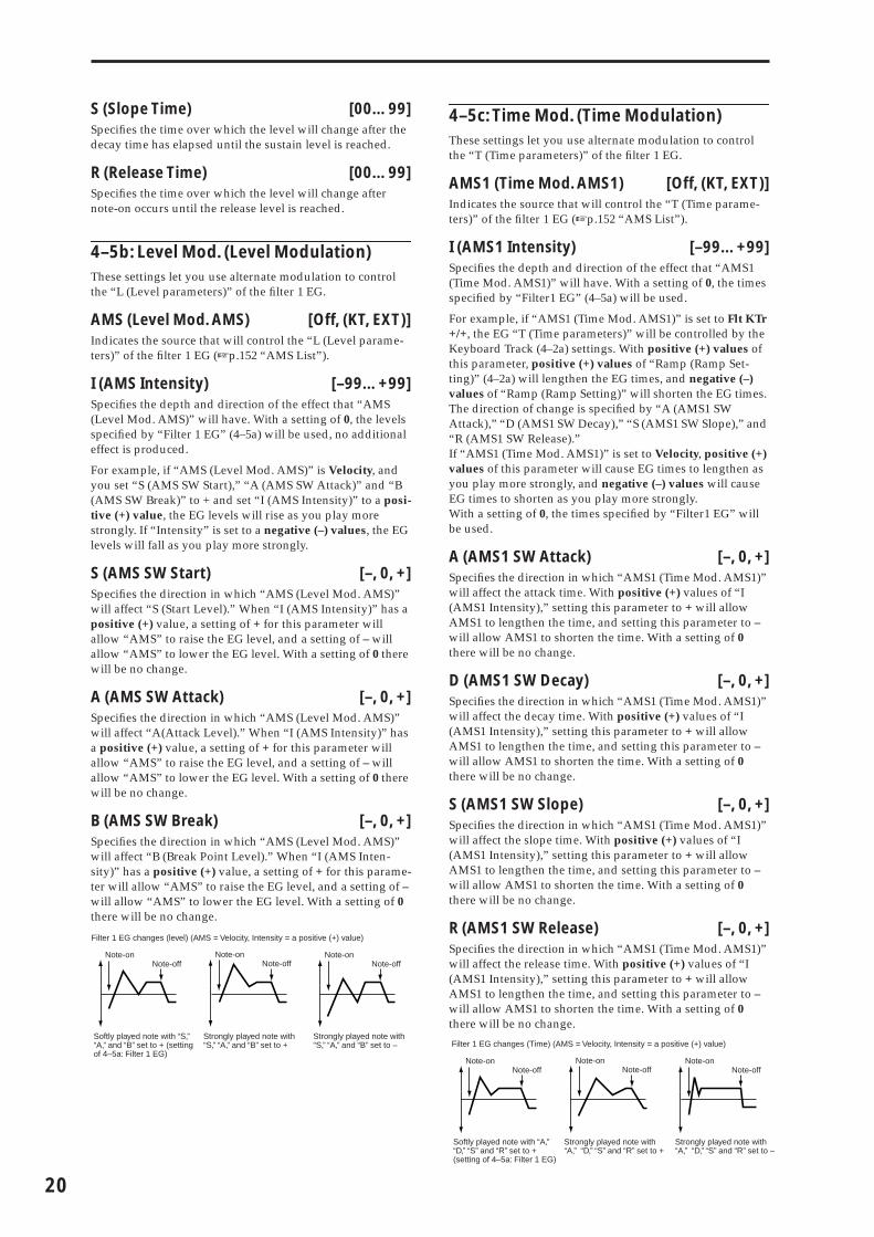
20
S (Slope Time) [00…99]Specifies the time over which the level will change after the decay time has elapsed until the sustain level is reached.
R (Release Time) [00…99]Specifies the time over which the level will change after note-on occurs until the release level is reached.
4–5b: Level Mod. (Level Modulation)These settings let you use alternate modulation to control the “L (Level parameters)” of the filter 1 EG.
AMS (Level Mod. AMS) [Off, (KT, EXT)]Indicates the source that will control the “L (Level parame-ters)” of the filter 1 EG (☞p.152 “AMS List”).
I (AMS Intensity) [–99…+99]Specifies the depth and direction of the effect that “AMS (Level Mod. AMS)” will have. With a setting of 0, the levels specified by “Filter 1 EG” (4–5a) will be used, no additional effect is produced.
For example, if “AMS (Level Mod. AMS)” is Velocity, and you set “S (AMS SW Start),” “A (AMS SW Attack)” and “B (AMS SW Break)” to + and set “I (AMS Intensity)” to a posi-tive (+) value, the EG levels will rise as you play more strongly. If “Intensity” is set to a negative (–) values, the EG levels will fall as you play more strongly.
S (AMS SW Start) [–, 0, +]Specifies the direction in which “AMS (Level Mod. AMS)” will affect “S (Start Level).” When “I (AMS Intensity)” has a positive (+) value, a setting of + for this parameter will allow “AMS” to raise the EG level, and a setting of – will allow “AMS” to lower the EG level. With a setting of 0 there will be no change.
A (AMS SW Attack) [–, 0, +]Specifies the direction in which “AMS (Level Mod. AMS)” will affect “A(Attack Level).” When “I (AMS Intensity)” has a positive (+) value, a setting of + for this parameter will allow “AMS” to raise the EG level, and a setting of – will allow “AMS” to lower the EG level. With a setting of 0 there will be no change.
B (AMS SW Break) [–, 0, +]Specifies the direction in which “AMS (Level Mod. AMS)” will affect “B (Break Point Level).” When “I (AMS Inten-sity)” has a positive (+) value, a setting of + for this parame-ter will allow “AMS” to raise the EG level, and a setting of – will allow “AMS” to lower the EG level. With a setting of 0 there will be no change.
4–5c: Time Mod. (Time Modulation)These settings let you use alternate modulation to control the “T (Time parameters)” of the filter 1 EG.
AMS1 (Time Mod. AMS1) [Off, (KT, EXT)]Indicates the source that will control the “T (Time parame-ters)” of the filter 1 EG (☞p.152 “AMS List”).
I (AMS1 Intensity) [–99…+99]Specifies the depth and direction of the effect that “AMS1 (Time Mod. AMS1)” will have. With a setting of 0, the times specified by “Filter1 EG” (4–5a) will be used.
For example, if “AMS1 (Time Mod. AMS1)” is set to Flt KTr +/+, the EG “T (Time parameters)” will be controlled by the Keyboard Track (4–2a) settings. With positive (+) values of this parameter, positive (+) values of “Ramp (Ramp Set-ting)” (4–2a) will lengthen the EG times, and negative (–) values of “Ramp (Ramp Setting)” will shorten the EG times. The direction of change is specified by “A (AMS1 SW Attack),” “D (AMS1 SW Decay),” “S (AMS1 SW Slope),” and “R (AMS1 SW Release).”If “AMS1 (Time Mod. AMS1)” is set to Velocity, positive (+) values of this parameter will cause EG times to lengthen as you play more strongly, and negative (–) values will cause EG times to shorten as you play more strongly.With a setting of 0, the times specified by “Filter1 EG” will be used.
A (AMS1 SW Attack) [–, 0, +]Specifies the direction in which “AMS1 (Time Mod. AMS1)” will affect the attack time. With positive (+) values of “I (AMS1 Intensity),” setting this parameter to + will allow AMS1 to lengthen the time, and setting this parameter to – will allow AMS1 to shorten the time. With a setting of 0 there will be no change.
D (AMS1 SW Decay) [–, 0, +]Specifies the direction in which “AMS1 (Time Mod. AMS1)” will affect the decay time. With positive (+) values of “I (AMS1 Intensity),” setting this parameter to + will allow AMS1 to lengthen the time, and setting this parameter to – will allow AMS1 to shorten the time. With a setting of 0 there will be no change.
S (AMS1 SW Slope) [–, 0, +]Specifies the direction in which “AMS1 (Time Mod. AMS1)” will affect the slope time. With positive (+) values of “I (AMS1 Intensity),” setting this parameter to + will allow AMS1 to lengthen the time, and setting this parameter to – will allow AMS1 to shorten the time. With a setting of 0 there will be no change.
R (AMS1 SW Release) [–, 0, +]Specifies the direction in which “AMS1 (Time Mod. AMS1)” will affect the release time. With positive (+) values of “I (AMS1 Intensity),” setting this parameter to + will allow AMS1 to lengthen the time, and setting this parameter to – will allow AMS1 to shorten the time. With a setting of 0 there will be no change.
Filter 1 EG changes (level) (AMS = Velocity, Intensity = a positive (+) value)
Note-onNote-off
Note-onNote-off
Note-onNote-off
Softly played note with “S,” “A,” and “B” set to + (setting of 4–5a: Filter 1 EG)
Strongly played note with “S,” “A,” and “B” set to +
Strongly played note with “S,” “A,” and “B” set to – Filter 1 EG changes (Time) (AMS = Velocity, Intensity = a positive (+) value)
Note-onNote-off
Note-onNote-off
Note-onNote-off
Softly played note with “A,” “D,” “S” and “R” set to + (setting of 4–5a: Filter 1 EG)
Strongly played note with “A,” “D,” “S” and “R” set to +
Strongly played note with “A,” “D,” “S” and “R” set to –

PR
OG
0 1
23
45
67
89
AMS2 (Time Mod. AMS2) [Off, (KT, EXT)]I (AMS2 Intensity) [–99…+99]A (AMS2 SW Attack) [–, 0, +]D (AMS2 SW Decay) [–, 0, +]S (AMS2 SW Slope) [–, 0, +]R (AMS2 SW Release) [–, 0, +]These parameters are the settings for “AMS2” to control the “Time” parameters of the filter 1 EG (☞“AMS1 (Time Moc. AMS1)”–“R (AMS1 SW Release)”).
■ 4–5: UTILITY
☞“Write Program” (0–1), “Copy Oscillator,” “Swap Oscilla-tor” (1–1)
For details on how to select the desired utility function, refer to “PROG 0–1: UTILITY.”
Sync Both EGsChoose “Sync Both EGs” from the utility menu, and press the center of the ClickPoint; a check mark will appear at the left of “Sync Both EGs,” and the “SYNC” icon will appear at the left of the envelope curve in the display.
In this state, the filter 1 EG and the filter 2 EG can be edited simultaneously. (Editing either one will cause the other to change.)
“Sync Both EGs” cannot sync the filter EG and amp EG independently. For example if you sync in 6–3d, it will be synced here as well.
This can be selected only if “Mode (Oscillator Mode)” (1–1a) is Double.
PROG 5: Ed–Filter2
5–1: Basic5–2: Mod.1 (Filter2 Modulation1)
5–3: Mod.2 (Filter2 Modulation2)
5–4: lfoMod (LFO Modulation)
5–5: EG (Filter2 EG)
Indicates settings for filter 2, which controls the tone of oscil-lator 2. You can select either a 24 dB/oct low pass filter with resonance, or a 12 dB/oct low pass filter and 12 dB/oct high pass filter connected in series. Filter 2 can be used when “Mode (Oscillator Mode)” (1–1a) is Double. (☞“PROG 4: Ed–Filter 1”)
PROG 6: Ed–Amp1/2
Here you can make settings for amp 1 which controls the volume of oscillator 1, and amp 2 which controls the volume of oscillator 2. You can also specify the panning of each oscil-lator.
6–1: Lvl/Pan (Amp1 Level/Pan)
These parameters control the volume and pan of oscillator 1.
6–1a: Amp1 Level
Level (Amp1 Level) [000…127]Sets the volume of oscillator 1.
The volume of a program can be controlled by CC#7 (volume) and CC#11 (expression). The resulting level is determined by summing the values of CC#7 and CC#11. The Global MIDI channel “MIDI Channel” (GLOBAL 1–1a) is used for control.
6–1b: Pan
Pan (Amp1 Pan)[Random, L001…C064…R127]
Sets the pan (stereo location) of oscillator 1.A setting of L001 places the sound at far left, C064 in the center, and R127 to far right.
Random: The sound will be heard from a different location at each note-on.
This can be controlled by CC#10 (panpot). A CC#10 value of 0 or 1 will place the sound at the far left, a value of 64 will place the sound at the location specified by the “Pan” setting for each oscillator, and a value of 127 will place the sound at the far right. This is con-trolled on the global MIDI channel “MIDI Channel” (GLOBAL 1–1a).
Use DKit Setting [Off, On]This is valid when “Mode (Oscillator Mode)” (1–1a) is set to Drums.
On (checked): The sound will be output at the “Pan” setting that has been made for each key of the drum kit (GLOBAL 4–3a). When “Mode (Oscillator Mode)” is Drums, you will normally use this setting.Off (unchecked): All notes will be output as specified by the “Pan (Amp1 Pan)” setting.
6–1a
6–1b
6–1c
21
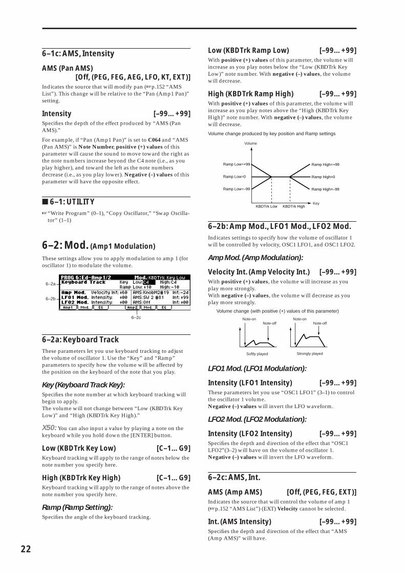
22
6–1c: AMS, Intensity
AMS (Pan AMS)[Off, (PEG, FEG, AEG, LFO, KT, EXT)]
Indicates the source that will modify pan (☞p.152 “AMS List”). This change will be relative to the “Pan (Amp1 Pan)” setting.
Intensity [–99…+99]Specifies the depth of the effect produced by “AMS (Pan AMS).”
For example, if “Pan (Amp1 Pan)” is set to C064 and “AMS (Pan AMS)” is Note Number, positive (+) values of this parameter will cause the sound to move toward the right as the note numbers increase beyond the C4 note (i.e., as you play higher), and toward the left as the note numbers decrease (i.e., as you play lower). Negative (–) values of this parameter will have the opposite effect.
■ 6–1: UTILITY☞“Write Program” (0–1), “Copy Oscillator,” “Swap Oscilla-
tor” (1–1)
6–2: Mod. (Amp1 Modulation)
These settings allow you to apply modulation to amp 1 (for oscillator 1) to modulate the volume.
6–2a: Keyboard TrackThese parameters let you use keyboard tracking to adjust the volume of oscillator 1. Use the “Key” and “Ramp” parameters to specify how the volume will be affected by the position on the keyboard of the note that you play.
Key (Keyboard Track Key):Specifies the note number at which keyboard tracking will begin to apply.The volume will not change between “Low (KBDTrk Key Low)” and “High (KBDTrk Key High).”
X50: You can also input a value by playing a note on the keyboard while you hold down the [ENTER] button.
Low (KBDTrk Key Low) [C–1…G9]Keyboard tracking will apply to the range of notes below the note number you specify here.
High (KBDTrk Key High) [C–1…G9]Keyboard tracking will apply to the range of notes above the note number you specify here.
Ramp (Ramp Setting):Specifies the angle of the keyboard tracking.
Low (KBDTrk Ramp Low) [–99…+99]With positive (+) values of this parameter, the volume will increase as you play notes below the “Low (KBDTrk Key Low)” note number. With negative (–) values, the volume will decrease.
High (KBDTrk Ramp High) [–99…+99]With positive (+) values of this parameter, the volume will increase as you play notes above the “High (KBDTrk Key High)” note number. With negative (–) values, the volume will decrease.
Volume change produced by key position and Ramp settings
6–2b: Amp Mod., LFO1 Mod., LFO2 Mod.Indicates settings to specify how the volume of oscillator 1 will be controlled by velocity, OSC1 LFO1, and OSC1 LFO2.
Amp Mod. (Amp Modulation):
Velocity Int. (Amp Velocity Int.) [–99…+99]With positive (+) values, the volume will increase as you play more strongly.With negative (–) values, the volume will decrease as you play more strongly.
LFO1 Mod. (LFO1 Modulation):
Intensity (LFO1 Intensity) [–99…+99]These parameters let you use “OSC1 LFO1” (3–1) to control the oscillator 1 volume. Negative (–) values will invert the LFO waveform.
LFO2 Mod. (LFO2 Modulation):
Intensity (LFO2 Intensity) [–99…+99]Specifies the depth and direction of the effect that “OSC1 LFO2”(3–2) will have on the volume of oscillator 1. Negative (–) values will invert the LFO waveform.
6–2c: AMS, Int.
AMS (Amp AMS) [Off, (PEG, FEG, EXT)]Indicates the source that will control the volume of amp 1 (☞p.152 “AMS List”) (EXT) Velocity cannot be selected.
Int. (AMS Intensity) [–99…+99]Specifies the depth and direction of the effect that “AMS (Amp AMS)” will have.
6–2a
6–2b
6–2c
Volume
Key
Ramp Low=+99
Ramp Low=0
Ramp Low=–99
Ramp High=+99
Ramp High=0
Ramp High=–99
KBDTrk Low KBDTrk High
Volume change (with positive (+) values of this parameter)
Softly played Strongly played
Note-onNote-off
Note-onNote-off
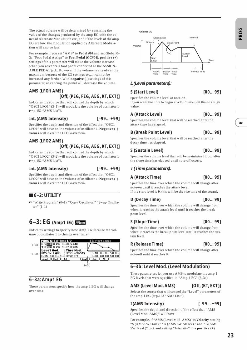
PR
OG
0 1
23
45
67
89
The actual volume will be determined by summing the value of the changes produced by the amp EG with the val-ues of Alternate Modulation etc., and if the levels of the amp EG are low, the modulation applied by Alternate Modula-tion will also be less.
For example if you set “AMS” to Pedal #04 and set Global 0–3a “Foot Pedal Assign” to Foot Pedal (CC#04), positive (+) settings of this parameter will make the volume increase when you advance a foot pedal connected to the ASSIGN-ABLE PEDAL jack. However if the volume is already at the maximum because of the EG settings etc., it cannot be increased any farther. With negative (–) settings of this parameter, advancing the pedal will decrease the volume.
AMS (LFO1 AMS)[Off, (PEG, FEG, AEG, KT, EXT)]
Indicates the source that will control the depth by which “OSC1 LFO1” (3–1) will modulate the volume of oscillator 1 (☞p.152 “AMS List”).
Int. (AMS Intensity) [–99…+99]Specifies the depth and direction of the effect that “OSC1 LFO1” will have on the volume of oscillator 1. Negative (–) values will invert the LFO waveform.
AMS (LFO2 AMS)[Off, (PEG, FEG, AEG, KT, EXT)]
Indicates the source that will control the depth by which “OSC1 LFO2” (3–2) will modulate the volume of oscillator 1 (☞p.152 “AMS List”).
Int. (AMS Intensity) [–99…+99]Specifies the depth and direction of the effect that “OSC1 LFO2” will have on the volume of oscillator 1. Negative (–) values will invert the LFO waveform.
■ 6–2: UTILITY☞“Write Program” (0–1), “Copy Oscillator,” “Swap Oscilla-
tor” (1–1)
6–3: EG (Amp1 EG)
Indicates settings to specify how Amp 1 will cause the vol-ume of oscillator 1 to change over time.
6–3a: Amp1 EGThese parameters specify how the amp 1 EG will change over time.
L (Level parameters):
S (Start Level) [00…99]Specifies the volume level at note-on.If you want the note to begin at a loud level, set this to a high value.
A (Attack Level) [00…99]Specifies the volume level that will be reached after the attack time has elapsed.
B (Break Point Level) [00…99]Specifies the volume level that will be reached after the decay time has elapsed.
S (Sustain Level) [00…99]Specifies the volume level that will be maintained from after the slope time has elapsed until note-off occurs.
T (Time parameters):
A (Attack Time) [00…99]Specifies the time over which the volume will change after note-on until it reaches the attack level.If the start level is 0, this will be the rise time of the sound.
D (Decay Time) [00…99]Specifies the time over which the volume will change from when it reaches the attack level until it reaches the break point level.
S (Slope Time) [00…99]Specifies the time over which the volume will change from when it reaches the break point level until it reaches the sus-tain level.
R (Release Time) [00…99]Specifies the time over which the volume will change after note-off until it reaches 0.
6–3b: Level Mod. (Level Modulation)These parameters let you use AMS to modulate the amp 1 EG levels that were specified in “Amp 1 EG” (6–3a).
AMS (Level Mod. AMS) [Off, (KT, EXT)]Selects the source that will control the “Level” parameters of the amp 1 EG (☞p.152 “AMS List”).
I (AMS Intensity) [–99…+99]Specifies the depth and direction of the effect that “AMS (Level Mod. AMS)” will have.
For example, if “AMS (Level Mod. AMS)” is Velocity, setting “S (AMS SW Start),” “A (AMS SW Attack),” and “B (AMS SW Break)” to + and setting “Intensity” to a positive (+)
6–3a
6–3b
6–3c
Note-on
Note-off
AttackTime
DecayTime
Release Time
Attack Level
SustainLevel
Time
Break Point
StartLevel
SlopeTime
Amplifier EG
Volume
23

24
value will cause the amp 1 EG volume levels to increase as you play more strongly. Setting “Intensity” to a negative (–) values will cause the amp 1 EG volume levels to decrease as you play more strongly. With a setting of 0, the levels will be as specified in “Amp 1 EG” (6–3a).
S (AMS SW Start) [–, 0, +]Specifies the direction in which “AMS (Level Mod. AMS)” will change “S (Start Level).” If “I (AMS Intensity)” is set to a positive (+) value, setting this parameter to + will allow AMS to increase the EG level, and setting this parameter to – will allow AMS to decrease the EG level. With a setting of 0, no change will occur.
A (AMS SW Attack) [–, 0, +]Specifies the direction in which “AMS (Level Mod. AMS)” will change “A (Attack Level).” If “I (AMS Intensity)” is set to a positive (+) value, setting this parameter to + will allow AMS to increase the EG level, and setting this parameter to – will allow AMS to decrease the EG level. With a setting of 0, no change will occur.
B (AMS SW Break) [–, 0, +]Specifies the direction in which “AMS (Level Mod. AMS)” will change “B (Break Point Level).” If “I (AMS Intensity)” is set to a positive (+) value, setting this parameter to + will allow AMS to increase the EG level, and setting this parame-ter to – will allow AMS to decrease the EG level. With a set-ting of 0, no change will occur.
6–3c: Time Mod. (Time Modulation)You can use two AMS sources to control the Amp 1 EG times that were specified in “Amp 1 EG” (6–3a).
AMS1 (Time Mod. AMS1) [Off, (EXT, KT)]Selects the source that will control the “Time” parameters of Amp 1 EG. (☞p.152 “AMS List”)
I (AMS1 Intensity) [–99…+99]Specifies the depth and direction of the effect that “AMS1 (Time Mod. AMS1)” will have.
For example, if “AMS1 (Time Mod. AMS1)” is Amp KT +/+, the (Amp) “Keyboard Track” settings (6–2a) will control the EG “Time” parameters. With positive (+) values of this parameter, positive (+) values of “Ramp (Ramp Setting)” will cause EG times to be lengthened, and negative (–) val-ues of “Ramp (Ramp Setting)” will cause EG times to be shortened. The direction of the change is specified by “A (AMS1 SW Attack),” “D (AMS1 SW Decay),” “S (AMS1 SW Slope),” and “R (AMS1 SW Release).”When “AMS1 (Time Mod. AMS1)” is Velocity, positive (+) values will cause EG times to lengthen as you play more strongly, and negative (–) values will cause EG times to shorten as you play more strongly. With a setting of 0, the EG times will be as specified in “Amp1 EG” (6–3a).
A (AMS1 SW Attack) [–, 0, +]Specifies the direction of the effect that “AMS1 (Time Mod. AMS1)” will have on “A (Attack Time).” With positive (+) values of “I (AMS1 Intensity),” setting this parameter to + will allow AMS1 to lengthen the time, and setting it to – will allow AMS1 to shorten the time. With a setting of 0 there will be no effect.
D (AMS1 SW Decay) [–, 0, +]Specifies the direction of the effect that “AMS1 (Time Mod. AMS1)” will have on “D (Decay Time).” With positive (+) values of “I (AMS1 Intensity),” setting this parameter to + will allow AMS1 to lengthen the time, and setting it to – will allow AMS1 to shorten the time. With a setting of 0 there will be no effect.
S (AMS1 SW Slope) [–, 0, +]Specifies the direction of the effect that “AMS1 (Time Mod. AMS1)” will have on “S (Slope Time).” With positive (+) values of “I (AMS1 Intensity),” setting this parameter to + will allow AMS1 to lengthen the time, and setting it to – will allow AMS1 to shorten the time. With a setting of 0 there will be no effect.
R (AMS1 SW Release) [–, 0, +]Specifies the direction of the effect that “AMS1 (Time Mod. AMS1)” will have on “R (Release Time).” With positive (+) values of “I (AMS1 Intensity),” setting this parameter to + will allow AMS1 to lengthen the time, and setting it to – will allow AMS1 to shorten the time. With a setting of 0 there will be no effect.
AMS2 (Time Mod. AMS2) [Off, (EXT, KT)]I (AMS2 Intensity) [–99…+99]A (AMS2 SW Attack) [–, 0, +]D (AMS2 SW Decay) [–, 0, +]S (AMS2 SW Slope) [–, 0, +]R (AMS2 SW Release) [–, 0, +]These parameters specify how “AMS2 (Time Mod. AMS2)” will control the amp 1 EG “Time” parameters (☞“AMS1 (Time Mod. AMS1)”–“R(AMS1 SW Release)”).
Softly played note when “S”=0 and “A” and “B” are set to + (settings of 6–3a: Amp 1 EG)
Strongly played note when “S”=0 and “A” and “B” are set to +
Strongly played note when “S”=0 and “A” and “B” are set to –
Amp 1 EG changes (Level) (AMS=Velocity, Intensity = a positive (+) value)
Note-onNote-off
Note-onNote-off
Note-onNote-off
Settings of 6–3a: Amp 1EG
Low-pitched note played with “A,” “D,” “S”, and “R” at +
High-pitched note played with “A,” “D,” “S”, and “R” at –
Amp 1 EG changes (Time) (AMS=Velocity, Intensity= a positive (+) value)
Amp 1 EG changes (Time)(AMS=Amp KTrk +/+, Intensity = a positive (+) value)(When Amp Keyboard Track (6–2a) Low Ramp= a positive (+) value, and High Ramp = a positive (+) value)
Note-onNote-off
Note-onNote-off
Note-onNote-off
Note-onNote-off
Note-onNote-off
Note-onNote-off
Softly played note with “A,” “D,” “S” and “R” at + (settings of 6–3a: Amp 1 EG)
Strongly played note with “A,” “D,” “S” and “R” at +
Strongly played note with “A,” “D,” “S” and “R” at –

PR
OG
0 1
23
45
67
89
■ 6–3: UTILITY
☞“Write Program” (0–1), “Copy Oscillator,” “Swap Oscilla-tor” (1–1)
For details on how to select the desired utility function, refer to “PROG 0–1: UTILITY.”
Sync Both EGsThe amp 1 EG and the amp 2 EG can be edited simulta-neously. (Editing either one will cause the other to change.) Choose “Sync Both EGs” from the utility menu, and press the center of the ClickPoint; a check mark will appear at the left of “Sync Both EGs.” (☞4–5: UTILITY )
6–4: Lvl/Pan (Amp2 Level/Pan)
6–5: Mod. (Amp2 Modulation)
6–6: EG (Amp2 EG)
These will appear when “Mode (Oscillator Mode)” (1–1a) is Double. (☞“PROG 6: Ed–Amp1/2”)
PROG 7: Ed–Arp/Ctrls (Arpeggiator/Controls)
Here you can make settings for the arpeggiator used in the program.You can also assign the functions of the following control-lers.
X50: The B-mode functions of REALTIME CONTROLS [1]–[4] knobs, and the functions of [SW1] and [SW2].
microX: The B-mode functions of REALTIME CONTROLS [1]–[4] knobs.
These arpeggiator settings can be linked when you switch programs. To link, check the Program item in “Auto Arp. “Program” (GLOBAL 0–1c): On.
The arpeggiator can be switched on/off by the [ARP ON/OFF] button. When on, the LED will light.
The settings of the REALTIME CONTROLS C-mode [ARP-GATE] knob, [ARP-VELOCITY] knob, [ARP-LENGTH] knob, [TEMPO] knob, and [ARP ON/OFF] button can be saved for each program.
These settings will be valid when Auto Arp. “Program” is On.
You can control the arpeggiator from an external sequencer, or record arpeggio note data on an external sequencer. (☞p.178)
“Pattern,” “Resolution,” “Octave,” “Sort,” “Latch,” “Key Sync.,” “Keyboard,” and “� (Tempo)” can also be set in the Arp. Play page of 0: Play.
7–1: Setup (Arpeg. Setup)
7–1a: Arpeggiator Setup☞Refer to OG X50: p.91, microX: p.91.
Pattern* [Preset-0...Preset-4, U000...U250]Selects the arpeggio pattern.
Preset-0–Preset-4 are preset arpeggio patterns, U000–U250 are user arpeggio patterns. User arpeggio patterns can be created in GLOBAL 5: Arp. Pattern.
X50: Arpeggio patterns U000–U250 can be selected using the numeric buttons [0]–[9] and the [ENTER] button.
Preset-0: UP Preset Arpeggio Pattern
Preset-1: DOWN Preset Arpeggio Pattern
Preset-2: ALT1 Preset Arpeggio Pattern
Preset-3: ALT2 Preset Arpeggio Pattern
Preset-4: RANDOM Preset Arpeggio Pattern
U000...U250 for Preloaded User Arpeggio Pattern
7–1a
7–1b
25

26
Octave* [1, 2, 3, 4]Specifies the number of octaves in which the arpeggio will be played.
If a user arpeggio pattern is selected, the range of the arpeggio will depend on the “Octave Motion” (GLO-BAL 5–1c) setting.
Reso (Resolution)* [ � � , � , � � , � , � � , � ]Specifies the timing resolution of the arpeggio. The notes of the arpeggio will be played at the interval you specify: � � , � , � �, � , � � , or � . The speed of the arpeggio pattern is determined by the “� (Tempo)” and the “Resolution.”
Gate [000...100(%), Step]Specifies the length (gate time) of each note in the arpeggio.000–100(%): Each note will be played with the specified gate time.Step: This is available when a user arpeggio pattern U000 –U250 is selected for “Pattern.” When this is selected, the gate time specified for each step will be used.
The gate time can also be controlled by the REALTIME CONTROLS C-mode [ARP-GATE] knob. Rotating the knob toward the left will shorten the gate time, and rotating it toward the right will lengthen the gate time. When the knob is at the 12 o’clock position, the gate time will be as specified here.
Velocity [001...127, Key, Step]Specifies the velocity of the notes in the arpeggio.001–127: Each note will sound with the specified velocity value.Key: Each note will sound with the velocity value at which it was actually played.Step: This is available when a user arpeggio pattern U000–U250 is selected for “Pattern.” When this is selected, the velocity specified for each step will be used.
The velocity can also be controlled by the REALTIME CON-TROLS C-mode [ARP-VELOCITY] knob. Rotating the knob toward the left will decrease the velocity, and rotating it toward the right will increase the velocity. When the knob is at the 12 o’clock position, the velocity will be as specified here.
Swing [–100...+100(%)]This parameter shifts the timing of the odd-numbered notes of the arpeggio.
Sort* [Off, On]This specifies the order in which the notes you press will be arpeggiated.
On (checked): Notes will be arpeggiated in the order of their pitch, regardless of the order in which you pressed them.Off (unchecked): Notes will be arpeggiated in the order in which you pressed them.
Latch* [Off, On]Specifies whether or not the arpeggio will continue playing after you take your hand off the keyboard.On (checked): The arpeggio will continue playing after you remove your hand from the keyboard.Off (unchecked): The arpeggio will stop when you remove your hand from the keyboard.
Key Sync.* [Off, On]Specifies whether the arpeggio pattern will begin when you press a key, or whether it will always follow the “� (Tempo)” setting.On (checked): The arpeggio pattern will start playing from the beginning when a note-on occurs from a condition where no keys are pressed. This setting is suitable when you are playing in realtime and want the arpeggio to play from the beginning of the measure.Off (unchecked): The arpeggio pattern will always play according to the “ � (Tempo) .”
Keyboard* [Off, On]This specifies whether the notes you play on the keyboard will be sounded as usual in addition to being sounded as part of the arpeggio.On (checked): The notes you play will be sounded on their own, in addition to being sounded as part of the arpeggio. For example if you simultaneously press two or more notes, they will be sounded as usual in addition to being played as arpeggiated notes.Off (unchecked): Only the arpeggiated notes will be heard.
* These parameters can also be set in “0–3: Arp. Play”
7–1b: Arpeggiator Tempo
� (Tempo) [040...240, EXT]Sets the tempo.
☞p.3 “� (Tempo)” (0–1a)
■ 7–1: UTILITY
☞“Write Program” (0–1)
Copy ArpeggiatorThis command copies arpeggio settings.
1 Select “Copy Arpeggiator” to access the dialog box.
2 In “From” specify the copy source arpeggio settings (mode, bank, number).
X50: You can press a PROG BANK button to select a bank. You can also use numeric buttons [0]–[9] and the [ENTER] button to select a number.
3 If you are copying from Combination or multi set, specify whether you wish to copy from A or B.
4 To execute the Copy Arpeggio operation, press the [MENU/OK] button. To cancel, press the [EXIT/CAN-CEL] button.
When Resolution =
Step 1 2 3 4 5 6 7 8 9
Swing–50 –25 +25 +25

PR
OG
0 1
23
45
67
89
7–2: Zone (Scan Zone)
7–2a: Scan Zone
Zone MapThis shows the “Scan Zone” setting.
Key:
Btm (Bottom Key) [C–1...G9]Top (Top Key) [C–1...G9]These parameters specify the range of notes (keys) for which the arpeggiator will function. “Top” is the upper limit, and “Btm” is the lower limit.
Vel:
Btm (Bottom Velocity) [001...127]Top (Top Velocity) [001...127]Specifies the range of velocities for which the arpeggiator will function. “Top” is the upper limit, and “Btm” is the lower limit.
X50: The note number and velocity can also be specified by holding down the [ENTER] button and pressing a note on the keyboard.
■ 7–2: UTILITY☞“Write Program” (0–1), “Copy Arpeggiator” (7–1)
7–3: Controls
X50
microX
7–3a: Knob B AssignHere you can assign functions (mainly various types of con-trol change) to the B-mode of the REALTIME CONTROLS knobs [1]–[4] (☞p.162 “Realtime Control Knobs B Assign List”).The functions you set here will take effect when you operate the REALTIME CONTROLS knobs [1]–[4] in B-mode.
Knob1–B (Knob1–B Assign)[Off...MIDI CC#95]
Knob2–B (Knob2–B Assign)[Off...MIDI CC#95]
Knob3–B (Knob3–B Assign)[Off...MIDI CC#95]
Knob4–B (Knob4–B Assign)[Off...MIDI CC#95]
X50: 7–3b: SW1/2 AssignThese settings assign functions to [SW1] and [SW2] (☞p.161 “SW1, SW2 Assign List”).
SW1 Assign [Off...Pitch Bend Lock]Here you can assign a function to [SW1].The on/off status of the switch is saved when the program is written. When you change the function, it will be reset to the “off” state.
SW1 Mode [Toggle, Momentary]Specifies the on/off behavior of [SW1].Toggle: The switch will alternate on/off each time you press [SW1].Momentary: The switch will be on only while you continue holding [SW1].
SW2 Assign [Off...Pitch Bend Lock]SW2 Mode [Toggle, Momentary]Here you can assign a function to [SW2].The functions that can be assigned to [SW2] are the same as for [SW1], with the exception of SW2 Mod. (CC#81) instead of SW1 Mod. (CC#80).
■ 7–3: UTILITY☞“Write Program” (0–1)
7–2a
7–3a
7–3b
7–3a
27

28
PROG 8: Ed–InsertFX
☞For details on insertion effect, refer to p.97 “6. Effect Guide.”
8–1: BUSThese settings specify the bus on which the output of the oscillator will be sent, and adjust the send levels to the mas-ter effects.
The following diagram shows the LCD screen when “Mode (Oscillator Mode)” (1–1a) is set to Single or Double.
8–1a: BUS
BUS Select:
BUS Select (All OSCs) [L/R, IFX, 1, 2, 1/2, Off]Specifies the bus to which oscillators 1 and 2 will be sent.
If this is set to 1/2, the oscillator pan settings (6–1b, 6–4) will be used to output the sound in stereo from (INDI-VIDUAL OUTPUT) 1/2. When the oscillator pan is controlled by CC#10 (pan) or AMS (Alternate Modula-tion Source), the sound will be output with the pan set-ting that is in effect at note-on. Unlike the case when this is set to L/R to output the sound from (MAIN OUT-PUT) L/MONO and R, the pan of a sounding note will not change in real-time.If you wish to adjust the pan in real-time while playing a note and output the sound from (INDIVIDUAL OUT-PUT) 1/2, set “BUS Select” to IFX, set “IFX” to 00: No Effect, and set the “BUS Select” (8–2a) after passing through IFX to 1/2.
MFX Send:
OSC1 Send1 [000...127]Sets the volume (send level) at which the output of OSC1 will be sent to master effect 1. This is valid when “BUS Select” is set to L/R or Off.If “BUS Select” is set to IFX, the send levels to master effect 1 and 2 are set by “S1 (Send1(MFX1))” and “S2 (Send2(MFX2))” (8–2a) after passing through IFX of the Setup page.
OSC1 Send2 [000...127]Sets the volume (send level) at which the output of OSC1 will be sent to master effect 2 (☞“OSC1 Send1”).
OSC2 Send1 [000...127]OSC2 Send2 [000...127]Sets the volume (send level) at which the output of OSC2 will be sent to master effects 1 and 2. These parameters will be valid when “Mode (Oscillator Mode)” (1–1a) is set to Double and “BUS Select” is set to L/R or Off (☞“OSC1 Send1”).
CC#93 will control the Send 1 level for OSC 1 and 2, and control change #91 will control the Send 2 level for OSC 1 and 2. These are controlled on the global MIDI channel “MIDI Channel” (GLOBAL 1–1a).The actual send level is determined by summing these values with the send level setting of each oscillator.
8–1b: Use DKit SettingThe LCD screen shown below is for when “Mode (Oscillator Mode)” (1–1a) is set to Drums.
Use DKit Setting [Off, On]This will be available when “Mode (Oscillator Mode)” is set to Drums. If the “Mode (Oscillator Mode)” is Single or Double, this setting has no effect.
On (checked): The “BUS (BUS Select)” (GLOBAL 4–3a) set-ting for each key of the selected drum kit will be used. Check this when you want to apply an insert effect to an individual drum instrument, or to output an individual drum instrument to one of the INDIVIDUAL OUTPUT jacks.Off (unchecked): The setting of the “BUS Select,” “MFX Send” (8–1a) parameter described below will be used. All drum instruments will be sent to the specified bus.
■ 8–1: UTILITY
☞“Write Program” (0–1)
For details on how to select the desired utility function, refer to “PROG 0–1: UTILITY.”
Copy Insert EffectThis command copies effect settings from Program, Combi-nation, Multi set.
1 Select “Copy Insert Effect” to access the dialog box.
2 In “From” select the copy source mode, bank, and num-ber.
X50: You can press a PROG BANK button to select a bank. You can also use numeric buttons [0]–[9] and the [ENTER] button to select a number.
3 Select the effect that you wish to copy. You can also copy from a master effect.
If you are copying from a master effect, the result may not be identical, due to differences in the routing and level settings of a master effect.
8–1a
8–1b

PR
OG
0 1
23
45
67
89
4 If you check “Post IFX Mixer Setting,” the “Pan (CC#8),” “BUS Select,” “S1 (Send1(MFX1))” and “S2 (Send2(MFX2))” settings that follow the copy source insert effect will also be copied. If you do not check this, only the effect type and its parameters will be copied.
5 To execute the Copy Insert Effect command, press the [MENU/OK] button. To cancel, press the [EXIT/CAN-CEL] button.
8–2: SetupHere you can select the type of insert effect, turn it on/off, pan etc.The direct sound (Dry) of an insert effect is always stereo input and output. The input/output of the effect sound (Wet) will depend on the effect type (☞p.98).
8–2a: InsertFX Setup
IFX On/Off [Off, On]Selects the insert effect on/off.When this is Off, the input will be output without change. (For 00: No Effect, on/off will produce the same result.)
Separately from this setting, you can use control change #92 to turn off insert effect. A value of 0 will be off, and a value of 1–127 will be the original setting. This mes-sage is received on the global MIDI channel specified by “MIDI Channel” (GLOBAL 1–1a).
Insert Effect [00...89: name]Indicates the type of insert effect.For “Insert Effect” you can select from 89 types of effect: 01: St.Amp Sim – 89: Reverb-Gate.
You can use the utility “Select by Category” (8–2c) to select these effects by category.
Pan(CC#8) (Post IFX Pan CC#8)[L000...C064...R127]
Sets the pan after the sound has passed through the insert effect. This setting is valid only when the “BUS Select” from the IFX output is set to L/R (☞p.99).
CC#8 will control the pan amount.
BUS Select [L/R, 1, 2, 1/2, Off]Specifies the bus to which the sound will be sent after pass-ing through the insert effect. Normally you will set this to L/R. If you wish to output to INDIVIDUAL OUTPUT, set this to 1, 2 or 1/2. The Off setting is used when you wish to use “S1 (Send1(MFX1))” and “S2 (Send2(MFX2))” and in addi-tion connect to the master effects in series.
S1 (Send1(MFX1)) [000...127]S2 (Send2(MFX2)) [000...127]Sets the send levels to the master effects 1 and 2 for the sound that has passed through the insert effect. These set-tings are valid when “BUS Select” (8–1a) has been set to L/R or Off.
Control change CC#93 will control the Send 1 level, and control change CC#91 will control the Send 2 level. These messages are received on the global MIDI chan-nel specified by “MIDI Channel” (GLOBAL 1–1a).
8–2b: RoutingThis displays the status of the insert effect.
This displays the routing of the insert effect, the specified effect name, and the on/off status.You can select (All OSCs) and use the VALUE controller to specify “BUS Select” (☞8–1a).
■ 8–2: UTILITY
☞“Write Program” (0–1), “Copy Insert Effect” (8–1)
For details on how to select the desired utility function, refer to “PROG 0–1: UTILITY.”
Select by CategorySelects insert effect by category. For the procedure, refer to “Select by Category” (☞p.2).
This command is valid when the 8–2 parameters are selected.
8–3: IFX (Insert Effect)
Here you can set the effect parameters for the IFX that was selected in the Setup page (☞p.104–).
Effect dynamic modulation (Dmod) is controlled on the global MIDI channel “MIDI Channel” (GLOBAL 1–1a). (☞p.157 “Dynamic Modulation Source (Dmod)” )
■ 8–3: UTILITY☞“Write Program” (0–1)
8–2a
8–2b
29

30
PROG 9: Ed–MasterFX
☞For details on master effects, refer to p.97 “6. Effect Guide.”
9–1: SetupHere you can select the master effect types, switch them on/off, specify chain order, and set the master EQ.
9–1a: Master Effect SetupThe master effects do not output the direct sound (Dry). The return level (“Rtn 1, 2”) sends the effect sound (Wet) to the L and R bus, and this is mixed with the direct sound (“BUS Select” L/R: 8–1a, 8–2a).The master effects are monaural input. The sound that is panned to L and R after passing through the oscillator and insert effect is mixed to a monaural signal as adjusted by the “S1 (Send1(MFX1))” and “S2 (Send2(MFX2))” levels, and input to the master effects.
The master effects are mono-in stereo-out. Even when a stereo-input type effect is selected, the input will be monaural.
MFX1 On/Off, MFX2 On/Off [Off, On]Switches master effect 1, 2 on/off. When off, the output will be muted.
Separately from this setting, you can use CC#94 to switch master effect 1 on/off, CC#95 to switch master effect 2 on/off. A value of 0 will be off, and a value of 1–127 will be the original setting. This is controlled on the global MIDI channel “MIDI Channel” (GLOBAL 1–1a).
Master Effect 1, 2 [00...89: name]Indicates the effect type for master effect 1, 2. You can select from 89 types of effect: 01: St.Amp Sim–89: Reverb-Gate. If 00: No Effect is selected, the output from the master effect will be muted.
Rtn 1, 2 (Return 1, 2) [000...127]Adjusts the return levels from the master effects to the L/R bus (main output L/MONO, R).
9–1b: Chain
MFX Chain [Off, On]On (checked): Chain (series connection) will be turned on for MFX1 and MFX2. (☞p.102)Off (unchecked): MFX 1 and MFX2 are operating in parallel.
Direction (Chain Direction)[MFX1→MFX2, MFX2→MFX1]
Specifies the direction of the connection when MFX1 and MFX2 are chained.
MFX1→MFX2: Connect from MFX1 to MFX2.MFX2→MFX1: Connect from MFX2 to MFX1.
Signal (Chain Signal) [L/R Mix, L Only, R Only]When chain is On, this parameter specifies how the stereo output signal of the first master effect will be connected to the input (mono) of the next master effect.
L/R Mix: The stereo output L/R of the first master effect will be mixed before being input to the next master effect.L Only, R Only: Only the left or right channel of the output will be input to the next master effect.
Level (Chain Level) [000...127]Sets the send level from the first master effect to the next master effect when chain is turned on.
9–1c: Master EQ Gain [dB]Sets the amount of cut and boost for the three-band EQ located immediately before the (MAIN OUTPUT) L/MONO and R jacks. This is linked with the various “Gain” parame-ters of Master EQ (9–4).
Low [–18.0...+18.0]Mid [–18.0...+18.0]High [–18.0...+18.0]The cutoff frequency for “Low,” “Mid” and “High” and the “Q” of “Mid” can be adjusted in the MEQ page. These set-tings are in “dB” units.
■ 9–1: UTILITY
☞“Write Program” (0–1)
For details on how to select the desired utility function, refer to “PROG 0–1: UTILITY.”
Copy Master EffectThis command lets you copy any desired effect settings from Program, Combination, Muliti set.
1 Select “Copy Master Effect” to access the dialog box.
2 In “From,” select the copy source mode, bank, and num-ber.
X50: You can press a PROG BANK button to select a bank. You can also use numeric buttons [0]–[9] and the [ENTER] button to select a number.
9–1a
9–1b
9–1c

PR
OG
0 1
23
45
67
89
3 Select the effect that you wish to copy. If you select MFX 1 or 2, “Rtn (Return)” (return level) will be copied at the same time. If you select Master EQ, only the master EQ settings will be copied. You can also copy from an insert effect. If you check “All,” all settings of the master effects and master EQ will be copied.
If you copy from an insert effect the result may not be identical, due to differences in routing and level set-tings.
4 In “To,” select the copy destination master effect.
5 To execute the Copy Master Effect command, press the [MENU/OK] button. To cancel, press the [EXIT/CAN-CEL] button.
Swap Master EffectThis command swaps (exchanges) the settings of MFX1 and MFX2.
1 Select “Swap Master Effect” to access the dialog box.
2 To execute the Swap Master Effect command, press the [MENU/OK] button. To cancel, press the [EXIT/CAN-CEL] button.
Select by CategorySelects master effects by category. For the procedure, refer to “Select by Category” (☞p.2).
This command is valid when the 9–1a parameters are on.
9–2: MFX 1 (Master Effect1)
9–3: MFX 2 (Master Effect2)
Indicates effect parameter settings for the MFX1 and 2 effects that were selected in the Setup page (☞p.104–).
Effect dynamic modulation (Dmod) is controlled on the global MIDI channel “MIDI Channel” (GLOBAL 1–1a). (☞p.157 “Dynamic Modulation Source (Dmod)”)
■ 9–2(3): UTILITY☞“Write Program” (0–1)
9–4: MEQ (Master EQ)
The master EQ is a three-band stereo EQ. It is used to adjust the overall tonality of the sound immediately before the L/R bus is output to the (MAIN OUTPUT) L/MONO and R jacks (☞p.149). The MEQ High Gain and the MEQ Low Gain can be controlled by assigning a modualtion source to the “Low Gain Mod-Src.” and “High Gain Mod-src.” functions on this page.
■ 9–4: UTILITY☞“Write Program” (0–1)
31

32

2. Combination mode
CO
MB
I0
12
34
56
78
9
COMBI PAGE MENU
For details on how to select pages in Combination mode, refer to p.1.
COMBI 0: Play
In this display page you can select and play Combinations. A Combi allows you to use up to 8 programs at one time.
0–1: Combi (Combination)
X50
microX
0–1a: Bank, Combi Select, Category, Cat.Hold, 10’s Hold, � (Tempo)
Bank (Bank Select) [Bank A…C]This is the Combination bank display.On this instrument, there are a total of 384 combination pro-grams in three rewritable banks (A, B, C), each containing 128 combinations.
X50: Use the front panel COMBI BANK [A]–[C] buttons to select the bank.
microX: Use the front panel COMBINATION [A]–[C] but-tons to select the bank. If you press one of the COMBINA-TION [A]–[C] buttons, you will automatically enter Combination mode regardless of the mode in which you were.
Combi Select (Combination Select)[0...127: name]
Here you can select a combination. Choose this parameter, and use one of the following methods to select a combina-tion.
X50: • Turn the [VALUE] dial.• Use the [INC][DEC] buttons.• Use the numeric buttons [0]–[9] to enter a program
number, and press the [ENTER] button to finalize the number.
Play 0: Play Select and play combinations. Select a program for each timbre, and make, pan and level settings.Select an arpeggio pattern and make settings.microX: Select an external control set. (☞p.33)
Tone Adjust 1: Ed–Tone Adjust Select the program used by each timbre.Specify the pan and volume of each pro-gram.Use Tone Adjust to adjust parameters. (☞p.38)
Track Parameter 2: Ed–Track Param MIDI, OSC, Pitch, delay, and scale set-tings for each timbre. (☞p.40)
MIDI Filter 1 3: Ed–MIDI Filter1 MIDI message transmission/reception fil-ter settings for each timbre, such as Prog Change, JS, Ribbon and After Touch. (☞p.42)
MIDI Filter 2 4: Ed–MIDI Filter 2 MIDI message transmission/reception fil-ter settings for each timbre, such as REALTIME CONTROL Knob, SW, and Other Ctrl Change (☞p.44)
Key Zone 5: Ed–Key Zone Key zone settings for each timbre. (☞p.45)
Velocity Zone 6: Ed–Vel Zone Velocity zone settings for each timbre. (☞p.46)
Arp/Controls 7: Ed–Arp/Ctrls Arpeggiator settings. (Same as the 0: Play parameters; can be edited from either page.)Controller settings. (☞p.47)
Insert Effect 8: Ed–InsertFX Bus and master effect send level settings for each timbre.Insert effect routing, selection, and set-tings. (☞p.50)
Master Effect 9: Ed–MasterFX Master effect selection and settings. Master EQ settings. (☞p.52)
Bank A
Preloaded combinationsBank B
Bank C
0–1a
0–1b
0–1a
0–1b
33

34
• Press the center of the ClickPoint to highlight the field, then use [π][†] to select a program, and press the center to finalize your selection.
• 10’s HOLD (☞p.34)• Use COMBI BANK [A]–[C] to select a bank (☞p.33)• Use “Cat. HOLD” to select by category (☞p.34)• Use “Select by Category” to select by category (☞p.34)• Use the foot switch (☞p.80, 164)• Receive a MIDI program change (☞p.171)
microX: • Turn the [VALUE] dial.• Press the center of the ClickPoint to highlight the field,
then use [π][†] to select a program, and press the center to finalize your selection.
• Use “Select by Category” to select by category (☞p.34)• Use the [CATEGORY] button and PROGRAM/
COMBINATION buttons to select by category (☞p.2)• Use the foot switch (☞p.80, 164)• Receive a MIDI program change (☞p.171)
Category [00...15: name]This is the combination category display.All combinations are organized into sixteen categories. You can select a category, and then select from combinations that belong to that category.
To select a combination by category, use the procedure described below. (☞PROG 0–1a)
To specify the category for a combination, use Utility “Write Combination” (0–1). To modify a category name, use “Category Name Comb. 00–07, 08–15” (GLOBAL 3–3/4).
Select by CategoryUse the utility “Select by Category” to select a combination by category. (☞PROG 0–1a)
microX: Category & BankUse the [CATEGORY] button and PROGRAM/COMBINA-TION buttons to select by category (☞p.2)
X50: Cat.HOLDPress the [./HOLD] button and the display will indicate
. The category will be held (fixed). (☞PROG 0–1a)To cancel, press the [./HOLD] button twice to turn off the
display.
X50: 10’s HOLDWhen you press the [./HOLD] button a second time, the dis-play will indicate , and the first digit of the combi-nation number will be fixed. (☞PROG 0–1a) To cancel, press the [./HOLD] button to turn off the
display.
� (Tempo) [040...240, EXT]Sets the tempo of the arpeggiator. This can be adjusted by the REALTIME CONTROLS C-mode [TEMPO] knob.EXT is shown if “MIDI Clock” (GLOBAL 1–1a) is set to Ext-MIDI or Ext-USB, or if it is set to Auto and the unit is oper-ating as a slave. The arpeggiator will synchronize to MIDI clock messages from an external MIDI device.You can also set this parameter from 7: Ed–Arp/Ctrls, Setup.
X50: You can tap the [ENTER] button several times to set the tempo to the corresponding interval. Alternatively, if you set the GLOBAL 0–3: Foot page “Foot SW Assign” parameter to Tap Tempo, you can specify the tempo by tap-
ping your foot on a pedal switch connected to the ASSIGN-ABLE SWITCH jack.
microX: If you set the GLOBAL 0–3: Foot page “Foot SW Assign” parameter to Tap Tempo, you can specify the tempo by tapping your foot on a pedal switch connected to the ASSIGNABLE SWITCH jack.
0–1b: Combination Information
X50: Displays information about the selected combination. This shows the functions that are assigned to “SW1,” “SW2,” and the REALTIME CONTROLS B-mode [ASSIGN-ABLE 1–4] knobs.
microX: Displays information about the selected combina-tion. This shows the functions that are assigned to the REALTIME CONTROLS B-mode [ASSIGNABLE 1–4] knobs.
■ 0–1: UTILITY
For details on how to select the desired utility function, refer to “PROG 0–1: UTILITY.”
Write CombinationThis command writes an edited combination into this instrument’s internal memory. Be sure to write any combination that you wish to keep. If the power is turned off or a different combination selected before you write an edited combination, your edits cannot be recovered.
For the procedure, refer to “Write Program” (PROG 0–1).
If you use “Category” to specify a category for the combina-tion that you are writing, you will be able to select it by cate-gory when selecting combinations in COMBI 0: Play.
Solo Selected TimbreThe Solo function will alternately be switched on/off each time you select “Solo Selected Timbre.”
1 Choose “Solo Selected Timbre” from the utility menu, and press the center of the ClickPoint to execute. When you execute, a check mark will be shown at the left of the “Solo Selected Timbre” in the menu, and the Solo func-tion will be turned on.
2 In pages that show parameters for an individual timbre, you can select a timbre to Solo (in 0: Play, Prog page “Pro-gram Select,” etc.) so that only that timbre will sound and the other timbres will be muted. The “Selected Timbre Information” (0–2d) in each page will indicate “Solo.”To solo a different timbre, select a parameter of the tim-bre that you wish to solo.
3 To defeat the Solo function, choose “Solo Selected Tim-bre” from the utility menu once again, and press the cen-ter of the ClickPoint.
If a timbre that is muted by the Solo function has been set to a “Status” (2–1a) of EXT or EX2, MIDI note-on/off messages will not be transmitted by that timbre.

CO
MB
I0
12
34
56
78
9
Select by CategorySelects a combination by category. For the procedure, refer to “Select by Category” (☞p.2)
X50
microX
0–2: Prog (Timbre Program)
Indicates the program that will be used by each timbre.
0–2a: Bank, Combi Select, Cat.Hold, 10’s Hold, � (Tempo)
Bank [Bank A…C]Combi Select (Combination Select)
[0…127: name]X50: Cat. (Cat. HOLD)X50: 10’s (10’s HOLD)� (Tempo) [040...240, EXT]In the same way as in the Combi page, select a combination and set the tempo of the arpeggiator. (☞0–1a)
0–2b: Timbre Number & Category
Timbre Number & Category 1...8This displays the timbre number and an abbreviated cate-gory name.
0–2c: Program Select, Program Name
Program Select [A000...g128]Indicates the program that will be used by each timbre.Choose this parameter, and use one of the following meth-ods to select a program.
X50: • Turn the [VALUE] dial.• Use the [INC][DEC] buttons.• Use numeric buttons [0]–[9] to enter the program
number, and press the [ENTER] button to confirm.
• Press the center of the ClickPoint to highlight the field in the display, use [π][†] to make your choice, and press the center to confirm.
• Use PROG BANK [A]–[GM] to select a bank (☞p.1)• Receive a MIDI program change to select a program
(☞p.171)
microX: • Turn the [VALUE] dial.• Press the center of the ClickPoint to highlight the field in
the display, use [π][†] to make your choice, and press the center to confirm.
• Use “Select by Category” to choose from the desired category (☞p.34)
• Receive a MIDI program change to select a program (☞p.171)
When you select a combination on this instrument, a MIDI program change for the selected combination number will be transmitted on the global MIDI channel “MIDI Channel” (GLOBAL 1–1a). At the same time, bank select, program change, and volume (CC#7) mes-sages will be transmitted on the MIDI channel specified for each timbre that is set to “Status” (2–1a) of EXT or EX2. However, these messages will not be transmitted for timbres that are set to the same MIDI channel as the global MIDI channel. In this case, EX2 timbres will show the “Program Select” Bank as “–”, and will trans-mit the bank number that was specified in “Bank (EX2) MSB” and “Bank (EX2) LSB” (2–1a).
MIDI messages transmitted when you operate this instrument are transmitted on the global MIDI channel. At the same time, timbres whose “Status” is EXT or EX2 will transmit the same messages on their own MIDI channel.
If bank select and program change messages are received on a MIDI channel that matches the MIDI channel of a timbre whose “Status” (2–1a) is INT, the program of that timbre will change. However if the MIDI channel of the incoming message matches the global MIDI channel “MIDI Channel,” then the combi-nation will change.
If you do not want the combination to change, you can either change the global MIDI channel so that it does not match the channel on which the program change messages are being received, or you can uncheck “Combi (Combi Change)” (GLOBAL 1–1b). Alternately, you can uncheck “Bank (Bank Change)” (GLOBAL 1–1b) so that only the program number will change and the bank will remain the same.
If you wish to change a program without changing the combination, you can also set “Program Change” (3–1a) so that the program will change on certain timbres but not on others.
This parameter can also be set from the 1: Ed–Tone Adjust, Prog page.
Program NameThis displays part of the program name selected for the tim-bre. In the case of the GM drums bank, drums bank (d) will be indicated.
0–2a0–2b
0–2c
0–2d
35

36
0–2d: Selected Timbre InformationThis shows information on the timbre (1–8) that is currently selected for editing.
Timbre No.: Bank No., Prog No.: and nameThis shows the timbre number, and the program bank, num-ber and name selected for that timbre.
Status (INT, Off, EXT, EX2)This shows the MIDI and internal tone generator status for each track.
Ch (01...16, Gch)This shows the MIDI channel number specified for the tim-bre.
■ 0–2: UTILITY
☞“Write Combination,” “Solo Selected Timbre” (0–1)
Select by Category(Combi/Category, Prog T1...T8/Category)Combinations or the programs used by each timbre can be selected by category.
If you have selected “Combi Select,” selecting Utility “Select by Category” will access the Combi/Category dialog box, allowing you to select a combination by category. (☞p.35)
If you have selected “Program Select,” selecting Utility “Select by Category” will access the Prog T1...T8/Category dialog box, allowing you to select a program for each timbre by category.
For the procedure of selecting by category, refer to p.2.
0–3: Mix (Mixer)
Here you can set the pan and volume for each timbre 1–8.
0–3a: Pan, Volume
Pan [RND, L001...C064...R127]Sets the pan for each timbre 1–8.L001...C064...R127: A setting of L001 is far left and R127 is far right. A setting of C064 will reproduce the pan setting that was made for the oscillator in Program mode.
If a mono-type insertion effect is inserted, the setting you make here will be ignored. In this case, the “Pan (CC#8)” parameter in 8: Ed–InsertFX, Setup page will adjust the pan-ning of the sound after the insertion effect (☞p.99 “3. Mixer”).
RND: The oscillator pan will change randomly at each note-on.
If “Status” (2–1a) has been set to INT, MIDI control change #10 (panpot) messages can be received to con-trol the setting. CC#10 values of 0 or 1 will place the sound at far left, 64 at center, and 127 at far right.Pan can be controlled by messages received on the “MIDI Channel” (2–1a).
This parameter can also be set from the 1: Ed–Tone Adjust, Mixer page.
Volume [000...127]Adjusts the volume of each timbre 1–8.
The volume of each timbre is determined by summing this volume value with the MIDI volume (CC#7) and expression (CC#11). If “Status” (2–1a) has been set to INT, incoming MIDI CC#7 or CC#11 messages will con-trol the volume of a timbre. (However these messages will not affect the setting of this parameter.)If “Status” is EXT or EX2, the value of this parameter will be transmitted as MIDI CC#7 when the combina-tion is changed. However this will not be transmitted by a timbre that is set to the same MIDI channel as the global MIDI channel. This message is transmitted on the “MIDI Channel” (2–1a) specified for each timbre.
This parameter can also be set from the 1: Ed–Tone Adjust, Mixer page.
■ 0–3: UTILITY
☞“Write Combination,” “Solo Selected Timbre” (0–1), “Select by Category” (0–1, PROG 0–1)
0–3a
OSC1: Amp1 Pan=L001OSC2: Amp2 Pan=R127
Left Center Right
Pan (CC#10)
C064
Left Center Right
L032
L001
R096
R127
Left Center Right
Left Center Right
OSC1 OSC2OSC1: Amp1 Pan=L032OSC2: Amp2 Pan=R096
Pan (CC#10)
C064
L032
L001
R096
R127
OSC1: Amp1 Pan=C064OSC2: Amp2 Pan=C064
Left Center Right
Pan (CC#10)
C064
Left Center Right
L032
L001
R096
R127
OSC1 OSC2

CO
MB
I0
12
34
56
78
9
Hold BalanceAdjusts the volume of the Combi while preserving the vol-ume balance between timbres 1–8.Select the “Volume” of any timbre, choose “Hold Balance” from the utility menu, and press the center of the ClickPoint. A check mark will appear at the left of “Hold Balance.” (The upper right of the LCD will indicate [Hold Bal.].)In this state, adjusting any “Volume” value will simulta-neously change the volume of the other timbres as well, while preserving the volume balance between timbres 1–8.
0–4: Arp. A (Arpeggio Play A)
0–5: Arp. B (Arpeggio Play B)
Here you can select the arpeggiator settings for the combina-tion. A combination can run two arpeggiators simulta-neously. Arpeggiator parameters can be edited in 7: Ed–Arp/Ctrls, but certain major parameters can be edited in these pages as well. You can edit these parameters in realtime, for example by changing the arpeggio pattern while playing in COMBI 0: Play.
To save the edits you make, use “Write Combination.” The arpeggiator can also be edited in realtime by the REALTIME CONTROLS C-mode [TEMPO] knob, [ARP-GATE] knob, [ARP-LENGTH] knob, and [ARP-VELOCITY] knob. (☞OG p.91)
0–4(5)a: Arpeggiator Run, Timbre assign
Arpeggiator Run A, B (Run A, B) [Off, On]When the [ARP ON/OFF] button is on, any arpeggiator that is checked here will run if it is assigned to a timbre in “Assign” (7–1b).Even if the arpeggiator is on, you can turn A and B on/off independently.This parameter can also be set from the 7: Ed–Arp/Ctrls Setup page.
Timbre assignThis displays the timbres 1–8 to which arpeggiators A and B are assigned. This can be set in “Assign” (7–1b).
0–4(5)b: Arpeggiator A(B)
Pattern [Preset-0...Preset-4, U000...U250]Reso (Resolution) [ � � , � , � � , � , � � , � ]Octave [1, 2, 3, 4]Sort [Off, On]Latch [Off, On]Key Sync. [Off, On]Keyboard [Off, On]Sets the various parameters of the combination arpeggiator (☞“PROG: Ed–Arp/Ctrls”).
These parameters can also be set in COMBI 7: Ed–Arp/Ctrls, Arp.A, Arp.B page.
■ 0–4(5): UTILITY☞“Write Combination,” “Solo Selected Timbre,” “Select by
Category” (0–1)
microX: 0–6: Ext. ControlExternal control lets you use the REALTIME CONTROLS knobs to control an external MIDI device. You can assign a MIDI control change and MIDI channel to each of the four knobs, and switch between three such settings (A, B, C) to control your external device. One set lets you transmit a total of twelve (4 × 3) different MIDI control changes. These are called “external control sets,” and you can choose from 64 such sets. (☞p.5)
This page only displays the settings that are assigned to knob sets A, B, and C. Use Global mode to make exter-nal control assignments.
0–6a: External Control
Ext. Control (Setup Select) [00...63]Selects an external control set.
This setting is not written (saved) in the combination.
Select [A, B, C]Shows the settings assigned to each knob of the external control set. The currently-enabled set is highlighted. Use the [SELECT] button to switch between groups (A, B, C).
MIDI Channel [01...16, Gch]Indicates the MIDI channelGch: The message will be transmitted on the global MIDI channel you specify in Global mode. The channel of all knobs that are set to Gch can be changed simply by chang-ing the global MIDI channel setting, instead of having to change the channel of each knob individually.
CC# Assign [Off, 000...119]Indicates the MIDI control change number transmitted by the knob.
■ 0–6: UTILITY☞“Write Combination,” “Solo Selected Timbre,” “Select by
Category” (0–1)
0–4a
0–4b
0–6a
37

38
COMBI 1: Ed–Tone Adjust
1–1: Prog (Timbre Program)
Indicates the bank and program for each timbre 1–8. These parameters can also be set from the 0: Play, Prog page.
1–1a: Program Select, Program Name
Program SelectIndicates the program that will be used by each timbre. (☞0–2c)
Program NameThis displays part of the program name selected for each timbre. (☞0–2c)
■ 1–1: UTILITY☞“Write Combination,” “Solo Selected Timbre” (0–1),
“Select by Category (Combi/Category, Prog T1...T8/Cate-gory)” (0–2)
1–2: Mix (Mixer)
Specifies the pan and volume for each timbre 1–8. These parameters can also be set from the 0: Play, Mixer page.
1–2a: Pan, Volume
PanSets the pan of each timbre 1–8. (☞0–3a)
VolumeSets the volume of each timbre 1–8. (☞0–3a)
■ 1–2: UTILITY☞“Write Combination,” “Solo Selected Timbre” (0–1)
1–3: TA1 (Tone Adjust 1)
1–4: TA2 (Tone Adjust 2)
1–5: TA3 (Tone Adjust 3)
You can also use the Tone Adjust function to temporarily adjust the tone of the program for each timbre.While creating a combination, you might use this function to soften the sound of a program or give it a faster attack so that it fits better within the combination, without having to return to Program mode and edit the program itself. For each timbre, you can assign and adjust up to six parameters such as the filter cutoff, resonance, filter EQ, and amp EG.
1–3(4)(5)a: Destination 1–6, Value 1–6
Destination 1–6 [LPF Fc…Reverse]Selects the parameter that you want to adjust.
Value 1–6 [–99…+99, –12.00…+12.00, –1200…+1200, Off…On]Specifies the value for the parameter you selected in “Desti-nation 1–6.” If you set this to +00 or PRG, the setting of the program will be used.
Normally, you should not select the same parameter for more than one “Destination” in the same track. How-ever if you do so, the parameters will operate as fol-lows.
If you select other than Hold or ReverseThe “Value” of each “Destination” set to the same parameter will be summed for each track. However, the “Value” of the parameter being controlled by the “Des-tination” will not exceed the allowable range of set-tings. For example if you have assigned three Detune1 settings for the same track, and their “Value” settings are set to +1000, +1000, and +1000 respectively, then the result will be +1200. (The sum is +3000, but the value is limited at the maximum of +1200 for the Detune1 parameter.) Settings of +1000, +1000, and –1000 would produce a result of +1000.
Hold, ReverseThe last of the multiple “Destination” settings will be valid.
“Destination 1–6” and “Value 1–6”The parameters that can be controlled and their range of val-ues are as follows.
LPF Fc (Low Pass Filter Cutoff Frequency)[–99…+00…+99]
Adjusts the low pass filter cutoff frequency of program OSC 1/2. This will affect the brightness of the sound. The param-eter will be controlled in the same way as when CC#74 is received. (☞p.175)
1–1a1–1b1–1c
1–1d
1–2a
1–3a

CO
MB
I0
12
34
56
78
9
Reso.HP (Resonance/High Pass Filter Cutoff Frequency) [–99…+00…+99]Adjusts the resonance level of the low pass filter or the cut-off frequency of the high pass filter for program OSC 1/2. The parameter that is controlled will depend on the filter type specified for the program. The parameter will be con-trolled in the same way as when CC#71 is received. (☞p.175)
F EG Int (Filter EG Intensity) [–99…+00…+99]Adjusts the filter EG intensity (the depth of the filter EG) for program OSC1/2. The parameter will be controlled in the same way as when CC#79 is received. (☞p.175)
A Vel I. (Amp Velocity Intensity) [–99…+00…+99]Adjusts the amp velocity intensity (the degree to which velocity will affect the amp) for program OSC 1/2. This con-trols the Amp Modulation “Velocity Intensity” parameter (☞p.22 6–2b).
F.A EG A (Filter/Amp EG Attack Time)[–99…+00…+99]
Adjusts the EG attack times of the program OSC 1/2 filter and amp. To maximize the result of this adjustment, the Amp EG sustain level, attack level, start level modulation, and attack time modulation will also be adjusted at the same time. The parameter will be controlled in the same way as when CC#73 is received. (☞p.175)
F.A EG D (Filter/Amp EG Decay Time)[–99…+00…+99]
Adjusts the EG decay time and slope time of the program OSC 1/2 filter and amp. The parameter will be controlled in the same way as when CC#75 is received. (☞p.175)
F.A EG S (Filter/Amp EG Sustain Level)[–99…+00…+99]
Adjusts the EG sustain level of the program OSC 1/2 filter and amp. The parameter will be controlled in the same way as when CC#70 is received. (☞p.175)
F.A EG R (Filter/Amp EG Release Time)[–99…+00…+99]
Adjusts the EG release time of the program OSC 1/2 filter and amp. The parameter will be controlled in the same way as when CC#72 is received. (☞p.175)
F EG A (Filter EG Attack Time) [–99…+00…+99]F EG D (Filter EG Decay Time) [–99…+00…+99]F EG S (Filter EG Sustain Level) [–99…+00…+99]F EG R (Filter EG Release Time) [–99…+00…+99]These adjust only the filter parameter as in “A (Attack Time),” “D (Decay Time),” “S (Sustain Level),“ or “R (Release Time)” respectively. (☞PROG 4–5a)
A EG A (Amp EG Attack Time) [–99…+00…+99]A EG D (Amp EG Decay Time) [–99…+00…+99]A EG S (Amp EG Sustain Level) [–99…+00…+99]A EG R (Amp EG Release Time) [–99…+00…+99]These adjust only the amp parameter as in “A (Attack Time),” “D (Decay Time),” “S (Sustain Level),“ or “R (Release Time)” respectively. (☞PROG 6–3a, 6–6a)
LFO1 Sp (LFO1 Speed) [–199…+00…+199]Adjusts the LFO1 speed of program OSC 1/2. The parame-ter will be controlled in the same way as when CC#76 is received. (☞p.175)
PLFO1 I. (Pitch LFO1 Intensity)[–12.00…+00.00…+12.00]
Adjusts the program OSC 1/2 pitch LFO1 intensity (the depth of pitch modulation produced by LFO1). The parame-ter will be controlled in the same way as when CC#77 is received. (☞p.175)
LFO1 Fd (LFO1 Fade) [–99…+00…+99]Adjusts the program OSC 1/2 LFO1 “Fade” parameter (the time from when the LFO begins to take effect until it reaches the maximum level; 3–1a ☞p.14).
LFO1 Dl (LFO1 Delay) [–99…+00…+99]Adjusts the program OSC 1/2 pitch LFO1 delay (the time from note-on until the LFO begins to take effect). The parameter will be controlled in the same way as when CC#78 is received. (☞p.175)
P.Strch (Pitch Stretch) [–12…+00…+12]Simultaneously adjusts the program OSC 1/2 Transpose and Tune parameters. This lets you create a rich variety of tonal changes without impairing the character of the origi-nal sound.This controls the same parameters as Performance Editor - “Stretch (Pitch Stretch)” (0–2b). (☞p.4)
Dtune 1(Detune 1) [–1200…+0000…+1200]Adjusts the tuning of program OSC 1. This controls the OSC1 Multisample “Tune” parameter (1–2c ☞p.8).
Dtune 2 (Detune 2) [–1200…+0000…+1200]Adjusts the tuning of program OSC 2. This controls the OSC2 Multisample “Tune” parameter (1–2c ☞p.8).
This is valid only if the program’s “Oscillator Mode” (1–1a ☞p.6) is set to Double.
Hold [Off, PRG, On]Controls the program’s Voice Assign - “Hold” parameter (1–1b ☞p.6). If you turn this Off, the OSC1/2 Amp EG Release Time parameter will be set to 0 in order to make full use of the effect.Normally you can make effective use of this with a drum program. When you turn this Off, the key-off timing will be valid, letting you use the key-on/off timing to control the gate time. Sometimes you can obtain an interesting effect by turning this Off for a previously-created drum track.
Reverse [Off, PRG, On]Controls the “Rev (Reverse)” parameter (1–2b ☞p.8, GLO-BAL 4–1b ☞p.87) for each Multisample or Drumsample of program OSC1/2.If you turn this On, all multisamples and drum samples will play backward. If you turn this Off, all multisamples and drum samples will play normally. If you set this to PRG, the settings of the program (or the drum kit used by the pro-gram) will be used. Normally you can make effective use of this with a drum program.
■ 1–3(4)(5): UTILITY☞“Write Combination,” “Solo Selected Timbre” (0–1)
39

40
COMBI 2: Ed–Timbre Param
2–1: MIDIHere you can make MIDI settings for each timbre.
2–1a: Status, MIDI Channel, Bank(EX2) MSB/LSB
Status [INT, Off, EXT, EX2]Specifies the status of MIDI and the internal tone generator for each timbre.INT: When you play this instrument, the internal tone gen-erator will sound, and will also sound in respond to MIDI messages received from an external MIDI device. MIDI data will not be transmitted.Off: The program will not sound. Nor will MIDI data be transmitted.EXT: Playing this instrument will not cause it to sound, but it will transmit data via MIDI to control external MIDI devices.EX2: “Bank (EX2) MSB” and “Bank (EX2) LSB” (2–1a) will be enabled. Instead of the bank numbers for A–G(d) that can be selected on this instrument, the bank numbers you specify here will be transmitted via MIDI. In other respects this is the same as EXT.
MIDI Channel [01...16, Gch]Set the MIDI transmit/receive channel for each timbre 1–8.Gch: The timbre will use the channel that has been selected as the global MIDI channel “MIDI Channel” (GLOBAL 1–1a).
When “Status” is INT, MIDI messages will be received on the channel you specify here. If this setting is the same as the global MIDI channel, the internal tone generator will sound according to the internal settings. If this is set to EXT or EX2, playing this instrument will transmit MIDI messages on the MIDI channel specified here. (Messages will also be trans-mitted simultaneously on the global MIDI channel.)
Bank(EX2) MSB [000:000...127:127]Bank(EX2) LSB [000:000...127:127]Specifies the bank number that will be transmitted when “Status” is set to EX2. If “Status” is not set to EX2, this set-ting has no effect.
■ 2–1: UTILITY☞“Write Combination,” “Solo Selected Timbre” (0–1)
2–2: OSCThese settings specify how each timbre will be sounded.
2–2a: Force OSC Mode, OSC Select, Porta-mento
Force OSC Mode [PRG, Poly, Mono, LGT]Specifies the “Mode (Voice Assign Mode)” (PROG 1–1b) of the program selected for each timbre 1–8.PRG: The settings of the program will be used.Poly: The timbre will play polyphonically, regardless of the settings of the program.Mono: The timbre will play monophonically, regardless of the settings of the program.LGT (Legato): The timbre will play monophonically, with single triggering (legato).
With settings of Mono or LGT, the note priority will be according to the “Priority” (PROG 1–1b) setting of the pro-gram.
OSC Select [Both, OSC1, OSC2]Specifies the “Mode (Oscillator Mode)” (PROG 1–1a) of the program selected for each timbre 1–8. If the “Mode (Oscilla-tor Mode)” is Double, you can specify that either or both oscillators sound.Both: OSC1 and 2 will sound as specified by the settings of the program.OSC1: Only OSC1 will sound.OSC2: Only OSC2 will sound. If “Mode (Oscillator Mode)” is Single or Drums, there will be no sound.
Portamento [PRG, Off, 001...127]Indicates portamento settings for each timbre 1–8.PRG: Portamento will be applied as specified by the pro-gram settings.Off: Portamento will be off, even if the original program set-tings specified for it to be on.001...127: Portamento will be applied with the portamento time you specify here, even if it is turned off by the program settings.
If the “Status” (2–1a) is set to INT, CC#05 (portamento time) and CC#65 (portamento switch) messages will be received to control and change this setting. (If the set-ting is PRG, CC#05 portamento time will not be received.) These messages will be received on the MIDI channel specified for each timbre by “MIDI Channel” (2–1a).
■ 2–2: UTILITY☞“Write Combination,” “Solo Selected Timbre” (0–1)
2–1a
Tonegenerator
MIDI IN INT
MIDI OUT
EXT, EX2
2–2a

CO
MB
I0
12
34
56
78
9
2–3: PitchHere you can make pitch-related settings for each timbre.
2–3a: Transpose, Detune, Bend Range
Transpose [–24…+24]Adjusts the pitch of each timbre in semitone steps.12 units equal one octave.
When “Status” (2–1a) is INT, this parameter will affect the pitches sounded by the X50/microX. When “Status” is EXT, this parameter will affect the note numbers of the MIDI note messages that are transmitted.
For example if you make settings of +04 and +07 respectively for two timbres that are set to EXT, playing the C key will transmit a C note number on the global MIDI channel, and at the same time will also transmit E and G note numbers on the MIDI channels of those tim-bres.
Detune (BPM Adj.) [–1200...+1200]Adjusts the pitch of each timbre in one-cent units.0: Normal pitch.
You can also use the Utility “Detune BPM Adj.” (2–3b) page menu command to automatically make a detune setting from a calculation in BPM units.
“Transpose” and “Detune” can be controlled via MIDI RPN messages. Depending on the “Mode (Oscillator Mode)” (PROG 1–1a) settings of the programs used by timbres 1–8, they can be controlled as follows.When “Mode (Oscillator Mode)” is Single or DoubleMIDI RPN Coarse Tune can be received to control and change the setting of “Transpose,” and RPN Fine Tune can be received to control and change the setting of “Detune.”When “Mode (Oscillator Mode)” is Drums, MIDI RPN Coarse Tune and Fine Tune can be received to control and change the setting of “Detune.” The controllable range is ±1 octave for coarse tune and fine tune together.
Bend Range [PRG, –24...+24]Specifies the amount of pitch change that will occur when the pitch bender is operated, in semitone units.PRG: The pitch range specified by the program will be used.–24–+24: This setting will be used regardless of the setting in the program.
The MIDI RPN Pitch Bend Change message can be received to control this and change the setting. (How-ever it will not be received if this parameter is set to PRG.) This message is received on the MIDI channel for each timbre set by “MIDI Channel” (2–1a).
■ 2–3: UTILITY
☞“Write Combination,” “Solo Selected Timbre” (0–1)
Detune BPM AdjustIf the program of a timbre uses a phrase or rhythm loop multisample is matched to a specific BPM, you can use this Utility to modify its BPM value. “Detune BPM Adjust” changes the BPM of a phrase or rhythm by modifying its pitch.This is valid for a track when timbre “Detune” is selected. When this Utility is executed, the selected “Detune” value will be set automatically. (☞PROG 1–2c, 1–3, GLOBAL 4–1b, 4–2)
1 Select “Detune BPM Adjust” to access the dialog box.
2 In “From” specify the original BPM value. In “To” spec-ify the desired BPM value. The appropriate “Detune” value will be calculated automatically from these two values.
For example if you set “From” to 60 bpm and “To” to 120 bpm, the “Detune” parameter will be set to +1200 (one octave up).
3 To execute the Detune BPM Adjust command, press the [MENU/OK] button. To cancel, press the [EXIT/CAN-CEL] button.
The detune value that is calculated when you execute this command will be added to “Detune” +0000. You must set the “From” BPM value when “Detune” is +0000. For example if you execute “From” 60 bpm “To” 120 bpm, and then execute “From” 120 bpm “To” 60 bpm, this will not return the original result. (Rather, this will set Detune= –1200, which is one octave down.)
This command is valid when “Detune” (2–3a) is selected.
2–3a
41

42
2–4: OtherSpecifies the delay from note-on until sound is produced for each timbre. Also specifies the scale.
2–4a: Delay [ms], Use Prog’s Scale
Delay [ms] [0000…5000, KeyOff]Specifies a delay time from note-on until the sound begins for each timbre.
KeyOff: The note will begin sounding at note-off. In this case, the sound will not die away if the sustain level of the program’s amp EG is other than 0. This setting is used when creating harpsichord sounds.Normally you will set this to 0.
Use Prog’s Scale [Off, On]Each timbre can use the scale that is specified by “Scale” (PROG 1–1c).
On (checked): The scale specified by the program will be used.Off (unchecked): The scale specified by “Type (Combi’s Scale)” (2–4b) will be used.
2–4b: Combi’s Scale, Key, RandomSpecifies the scale that the combination will use.
Type (Combi’s Scale)[Equal Temperament...User Octave15]
Indicates the type of scale.
☞“Type (Scale Type)” (PROG 1–1c)
Key [C…B]Indicates the tonic key of the selected scale.
☞“Key” (PROG 1–1c)
Random [0…7]As this value is increased, an increasingly random devia-tion will be added to the pitch at each note-on.
☞“Random” (PROG 1–1c)
■ 2–4: UTILITY☞“Write Combination,” “Solo Selected Timbre” (0–1)
COMBI 3: Ed–MIDI Filter1
These settings allow you to apply filters to the MIDI data that will be transmitted and received by each timbre 1–8. For example even if two timbres are being played by the same MIDI channel, you can make settings so that the damper pedal will apply to one but not the other.
On (checked): Transmission and reception of MIDI data is enabled.When “Status” (2–1a) is INT, operations of the built-in con-trollers or incoming MIDI data will apply the effect of the checked item to the program of the corresponding timbre. (The effect dynamic modulation function is not affected by this setting.)When “Status” is EXT or EX2, operations of the built-in con-trollers will transmit MIDI data on the channel of that tim-bre. MIDI transmission and reception settings for this instrument are made in “MIDI Filter” (GLOBAL 1–1b).The MIDI Filter 1–3 and MIDI Filter 1–4 pages contain MIDI filters for assignable controllers (whose function can be set by the user), and if these are assigned to MIDI control changes, the filter settings will affect those control changes.
In this case, if the assignable controllers have been set to control changes that are also found in the MIDI Filter 1–1 or MIDI Filter 1–2 pages, the settings in the MIDI Filter 1 and MIDI Filter 2 pages will take priority. Also, if the same con-trol change is assigned to two or more controllers in the MIDI Filter 1–3 and MIDI Filter 1–4 pages, checking any one of them will enable that control change.
Off (unchecked): Transmission and reception of MIDI data is disabled.
3–1: MIDI 1–1 (MIDI Filter 1–1)
3–1a: Program Change, After Touch
Program Change [Off, On]Specifies whether or not MIDI program change messages will be transmitted and received.
After Touch [Off, On]Specify whether or not MIDI after touch messages will be transmitted and received.If you set the GLOBAL 0–3: Foot page “Foot Pedal Assign” parameter to After Touch, you can transmit aftertouch mes-sages using a foot controller connected to the ASSIGNABLE PEDAL jack.
The keyboard of the X50/microX does not transmit aftertouch messages.
■ 3–1: UTILITY☞“Write Combination,” “Solo Selected Timbre” (0–1)
2–4a
2–4b
3–1a

CO
MB
I0
12
34
56
78
9
3–2: MIDI 1–2 (MIDI Filter 1–2)
3–2a: Damper CC#64, Portamento SW CC#65
Damper CC#64 [Off, On]Specifies whether or not MIDI control change message #64 hold (damper pedal) messages will be transmitted and received.
Portamento SW CC#65 [Off, On]Specifies whether or not MIDI control change message #65 portamento on/off messages will be transmitted and received.
■ 3–2: UTILITY☞“Write Combination,” “Solo Selected Timbre” (0–1)
3–3: MIDI 1–3 (MIDI Filter 1–3)
3–3a: JS+Y/M.Whl CC#01, JS–Y CC#02
JS+Y/M.Whl CC#01 [Off, On]
X50: Specifies whether MIDI control change CC#1 (the X50’s [MOD] wheel or a REALTIME CONTROLS B-assign setting) will be transmitted and received.
microX: Specifies whether MIDI control change CC#1 (the +Y direction of the microX’s joystick or a REALTIME CON-TROLS B-assign setting) will be transmitted and received.
JS–Y CC#02 [Off, On]
X50: Specifies whether MIDI control change CC#2 (REAL-TIME CONTROLS B-mode assignment, or the GLOBAL 0–3: Foot page “Foot Pedal Assign” set to JS –Y (CC#02) to spec-ify the function of a foot controller connected to the ASSIGNABLE PEDAL jack) will be transmitted and received.
microX: Specifies whether MIDI control change CC#2 (the –Y direction of the microX’s joystick or a REALTIME CON-TROLS B-assign setting) will be transmitted and received.
■ 3–3: UTILITY☞“Write Combination,” “Solo Selected Timbre” (0–1)
3–4: MIDI 1–4 (MIDI Filter 1–4)
3–4a: JSX/PBend as AMS, Ribbon CC#16
JSX/PBend as AMS [Off, On]
X50: Specifies whether MIDI pitch bend messages (move-ment of the X50’s [PITCH] wheel) will apply the AMS (☞p.152 “Alternate Modulation Source”) assigned to Pitch Bend. (This is not a filter for MIDI pitch bend messages.)
microX: Specifies whether or not MIDI pitch bend mes-sages (the X axis of microX’s joystick) will be received to control the AMS (☞p.152 “Alternate Modulation Source”) effect assigned to JS X. (This is not a filter for MIDI pitch bend message reception.)
Ribbon CC#16 [Off, On]MIDI control change message CC#16 (realtime control knob B-assign, or the assignment of a ribbon controller on a TRI-TON Extreme or other instrument connected to the MIDI IN connector) will be transmitted and received.
■ 3–4: UTILITY☞“Write Combination,” “Solo Selected Timbre” (0–1)
3–2a
3–3a
3–2a
43

44
COMBI 4: Ed–MIDI Filter2
Specifies whether the A- and B-mode effects of REALTIME CONTROLS knobs [1], [2], [3], and [4] will be transmitted and received. The A-mode of each knob is fixed as a MIDI control change message. For B-mode, you can assign a MIDI control change message in 7: Ed–Arp/Ctrls.
X50: Specifies whether the effects of [SW1] and [SW2] will be received. The assignable switches [SW1] and [SW2] corre-spond to the messages that are assigned to the 7: Arp/Ctrls, Controls page.
4–1: MIDI 2–1 (MIDI Filter 2–1)
4–1a: Real-time Control Knob 1, 2
Knob1 [Off, On]Specifies whether MIDI control change message #74 (inter-nal low pass filter cutoff frequency) for the A-mode of knob [1] and the MIDI control change message assigned to the B-mode of knob [1] will be transmitted and received.
Knob2 [Off, On]Specifies whether MIDI control change message #71 (inter-nal low pass filter resonance or high pass filter cutoff fre-quency) for the A-mode of knob [2] and the MIDI control change message assigned to the B-mode of knob [2] will be transmitted and received.
■ 4–1: UTILITY☞“Write Combination,” “Solo Selected Timbre” (0–1)
4–2: MIDI 2–2 (MIDI Filter 2–2)
4–2a: Real-time Control Knob 3, 4
Knob3 [Off, On]Specifies whether MIDI control change message #79 (inter-nal filter EG intensity) for the A-mode of knob [3] and the MIDI control change message assigned to the B-mode of knob [3] will be transmitted and received.
Knob4 [Off, On]Specifies whether MIDI control change message #72 (inter-nal filter and amp EG release time) for the A-mode of knob [4] and the MIDI control change message assigned to the B-mode of knob [4] will be transmitted and received.
■ 4–2: UTILITY☞“Write Combination,” “Solo Selected Timbre” (0–1)
X50: 4–3: MIDI 2–3 (MIDI Filter2–3)
4–3a: SW1, SW2
SW1, SW2 [Off, On]Specifies whether the operations of [SW1] and [SW2] will be transmitted and received.These correspond to the control change messages assigned in 7: Ed–Arp/Ctrls.This filter setting is valid for settings of SW1 Mod.(CC#80), SW2 Mod.(CC#81), or Porta.SW(CC#65).
■ 4–3: UTILITY☞“Write Combination,” “Solo Selected Timbre” (0–1)
X50: 4–4: MIDI 2–4 (MIDI Filter 2–4)
microX: 4–3: MIDI 2–3 (MIDI Filter2–3)
X50
microX
4–1a
4–2a
4–3a
4–4a
4–3a

CO
MB
I0
12
34
56
78
9
X50: 4–4a: FootPedal/Switch, Other Con-trol Change/microX: 4–3a: FootPedal/Switch, Other Control Change
FootPedal/Switch [Off, On]Specifies whether or not the effect of the ASSIGNABLE PEDAL/SWITCH will be transmitted and received. The function is assigned in GLOBAL 0–3: System Foot page.This setting is valid when a MIDI control change is assigned.
Other Ctrl Change [Off, On]Specifies whether or not MIDI control change message not covered in the preceding items MIDI Filter1–1 – 2–4 will be transmitted and received.
■ X50: 4–4/microX: 4–3: UTILITY☞“Write Combination,” “Solo Selected Timbre” (0–1)
COMBI 5: Ed–Key Zone
These settings specify the keyboard range in which each timbre will sound.The top/bottom key parameters specify the range of notes in which timbres 1–8 will sound, and the top/bottom slope parameters specify the range over which the original vol-ume will be reached.
By setting timbres of different sounds to ranges that do not overlap, you can play different sounds in different ranges of the keyboard (Key Split).By setting the ranges to overlap, you can play two or more sounds with a single note (Layer).If you set the slopes (the grayed portion) to overlap, the sounds will overlap, and the proportion of the overlap will change according to the keyboard location (Positional Cross-fade).
5–1: Key (Key Zone)
5–1a: Key Zone Map (1)
This displays the range of note data that will sound the cur-rently selected track. The range of notes sounded is shown as a line, and the slope portion is shaded.
5–1b: Top Key, Bottom Key
Top Key [C–1...G9]Specifies the top key (upper limit) of the notes that will sound each timbre 1–8.
Bottom Key [C–1...G9]Specifies the bottom key (lower limit) of the notes that will sound each timbre 1–8.
It is not possible to set the bottom key above the top key of the same timbre. Nor is it possible for the top and bottom slopes to overlap.
X50: You can also set this parameter by holding down the [ENTER] button and playing a note.
How volume will change according to keyboard location
■ 5–1: UTILITY☞“Write Combination,” “Solo Selected Timbre” (0–1)
5–1a
5–1b
Bottom Key
Bottom Slope
Top Key
Top Slope
Bottom Key Top Key
Key
Volume
Bottom Slope Top Slope
45

46
5–2: Slope (Key Slope)
5–2a: Top Slope, Bottom Slope
Top Slope [00...72]Specifies the range of keys (12 is one octave) over which the maximum programmed volume level will be reached, start-ing from the top key.
0: The volume will be at the original level from the top key.12: The volume will increase gradually as you play down-ward, and will reach the original volume one octave below the top key.60: The volume will increase gradually as you play down-ward, and will reach the original volume five octaves below the top key.
Bottom Slope [00...72]Specifies the range of keys (12 is one octave) over which the maximum programmed volume level will be reached, start-ing from the bottom key.
0: The volume will be at the original level from the bottom key.12: The volume will increase gradually as you play upward, and will reach the original volume one octave above the bot-tom key.60: The volume will increase gradually as you play upward, and will reach the original volume five octaves above the bottom key.
■ 5–2: UTILITY☞“Write Combination,” “Solo Selected Timbre” (0–1)
5–3: Review
5–3a: Key Zone Map (All)
T1...T8This displays the range of notes that will sound for each of the timbres 1–8. The range of notes sounded is shown as a line, and the slope portion is shaded.
■ 5–3: UTILITY☞“Write Combination,” “Solo Selected Timbre” (0–1)
COMBI 6: Ed–Vel Zone (Velocity Zone)
Sets the Top/Bottom Velocity parameters to specify the range of velocities that will sound each timbre 1–8, and sets the Top/Bottom Slope parameters to specify the range over which the volume will change.By setting two or more timbres to velocity zones that do not overlap, you can use variations in playing dynamics to play different sounds (Velocity Switch).If you set two or more timbres to velocity zones that overlap, the sounds will be heard together (Layer).If the slope ranges (gray line) overlap, different sounds will be sounded together, and your playing dynamics will deter-mine the proportion of each sound (Velocity Cross-fade).
6–1: Vel (Velocity Zone)
6–1a: Velocity Zone Map (1)
This displays the range of velocities that will sound the cur-rently selected timbre. The range of velocities sounded is shown as a line, and the slope portion is shaded.
6–1b: Top Velocity, Bottom Velocity
Top Velocity [1…127]Specifies the maximum velocity value that each timbre 1–8 will sound.
Bottom Velocity [1…127]Specifies the minimum velocity value that each timbre 1–8 will sound.
It is not possible to set the bottom velocity greater than the top velocity for the same timbre. Nor can the top slope and the bottom slope overlap.
X50: You can also set this parameter by holding down the [ENTER] button and playing a note.
■ 6–1: UTILITY☞“Write Combination,” “Solo Selected Timbre” (0–1)
5–2a
5–3a
6–1a
6–1b
Bottom Velocity Top Velocity
Bottom Slope Top Slope
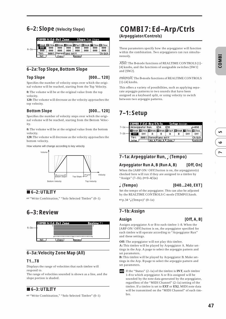
CO
MB
I0
12
34
56
78
9
6–2: Slope (Velocity Slope)
6–2a: Top Slope, Bottom Slope
Top Slope [000…120]Specifies the number of velocity steps over which the origi-nal volume will be reached, starting from the Top Velocity.
0: The volume will be at the original value from the top velocity.120: The volume will decrease as the velocity approaches the top velocity.
Bottom Slope [000…120]Specifies the number of velocity steps over which the origi-nal volume will be reached, starting from the Bottom Veloc-ity.
0: The volume will be at the original value from the bottom velocity.120: The volume will decrease as the velocity approaches the bottom velocity.
How volume will change according to key velocity
■ 6–2: UTILITY☞“Write Combination,” “Solo Selected Timbre” (0–1)
6–3: Review
6–3a: Velocity Zone Map (All)
T1...T8Displays the range of velocities that each timbre will respond to.The range of velocities sounded is shown as a line, and the slope portion is shaded.
■ 6–3: UTILITY☞“Write Combination,” “Solo Selected Timbre” (0–1)
COMBI 7: Ed–Arp/Ctrls (Arpeggiator/Controls)
These parameters specify how the arpeggiator will function within the combination. Two arpeggiators can run simulta-neously.
X50: The B-mode functions of REALTIME CONTROLS [1]–[4] knobs, and the functions of assignable switches [SW1] and [SW2].
microX: The B-mode functions of REALTIME CONTROLS [1]–[4] knobs.
This offers a variety of possibilities, such as applying sepa-rate arpeggio patterns to two sounds that have been assigned as a keyboard split, or using velocity to switch between two arpeggio patterns.
7–1: Setup
7–1a: Arpeggiator Run, (Tempo)
Arpeggiator Run A, B (Run A, B) [Off, On]When the [ARP ON/OFF] button is on, the arpeggiator(s) checked here will run if they are assigned to a timbre by “Assign” (7–1b). (☞0–4(5)a)
� (Tempo) [040...240, EXT]Set the tempo of the arpeggiator. This can also be adjusted by the REALTIME CONTROLS C-mode [TEMPO] knob.
☞p.34 “� (Tempo)” (0–1a)
7–1b: Assign
Assign [Off, A, B]Assigns arpeggiator A or B to each timbre 1–8. When the [ARP ON/OFF] button is on, the arpeggiator specified for each timbre will operate according to “Arpeggiator Run” and these settings.
Off: The arpeggiator will not play this timbre.A: This timbre will be played by Arpeggiator A. Make set-tings in the Arp. A page to select the arpeggio pattern and set parameters.B: This timbre will be played by Arpeggiator B. Make set-tings in the Arp. B page to select the arpeggio pattern and set parameters.
If the “Status” (2–1a) of the timbre is INT, each timbre 1–8 to which arpeggiator A or B is assigned will be sounded by the note data generated by the arpeggiator, regardless of the “MIDI Channel” (2–1a) setting of the timbre. If a timbre is set to EXT or EX2, MIDI note data will be transmitted on the “MIDI Channel” of each tim-bre.
6–2a
Bottom Slope Top Slope
Bottom Velocity Top Velocity
Velocity
Volume
6–3a
7–1a
7–1b
�
47

48
In this case, the arpeggiator can be triggered (operated) by any MIDI channel specified for the “MIDI Channel” parameter of any timbre 1–8 assigned to arpeggiator A or B.
If Local Control (“Local Control On,” GLOBAL 1–1a) is Off, the keyboard will not trigger the arpeggiator. The arpeggiator will be triggered via MIDI IN. Turn Local Control OFF if you have recorded only the trigger notes on an external sequencer, and wish to playback the external sequencer to trigger the X50/microX’s arpeg-giator.
If you want the note data generated by the arpeggiator to be recorded on the external sequencer, turn the X50/microX’s Local Control ON, and turn off the echo back function on your external sequencer.
You can control the arpeggiator from an external sequencer, or use an external sequencer to record arpeg-gio note data. (☞p.178)
Example 1) Set the “MIDI Channel” (2–1a) of timbres 1 and 2 to Gch, and set “Status” (2–1a) to INT. Assign arpeggiator A to timbre 1 and arpeggiator B to timbre 2, and check “Arpeggiator Run A, B” (0–4a/5a, 7–1a).
• When the front panel [ARP ON/OFF] button is off, timbres 1 and 2 will sound simultaneously (layered) when you play the keyboard.
• When the front panel [ARP ON/OFF] button is turned on, timbre 1 will be played by arpeggiator A, and timbre 2 will be played by arpeggiator B.
Example 2)The “MIDI Channel” (2–1a) of timbres 1, 2, 3, 4, and 5 are set respectively to Gch, Gch, 02, Gch, and 03. Their “Sta-tus” (2–1a) is set respectively to INT, Off, INT, Off, and INT. Assign arpeggiator A to timbres 2 and 3, assign arpeggiator B to timbres 4 and 5, and check “Arpeggiator Run A, B” (0–4a/5a, 7–1a).
• When the front panel [ARP ON/OFF] button is off, playing the keyboard will sound only timbre 1. (Timbres 2 and 4 are receiving the Gch, but they will not sound since their “Status” is Off.)
• When you turn on the front panel [ARP ON/OFF] button, arpeggiator A will operate for timbres 2 and 3, and arpeggiator B will operate independently for timbres 4 and 5. (Arpeggiators A and B are triggered by receiving note data on any MIDI channel of an assigned timbre, but in this example they are being triggered from the Gch.)
When you play the keyboard, arpeggiator A will operate for timbres 2 and 3, but only timbre 3 whose “Status” is INT will sound. Similarly, arpeggiator B will operate for timbres 4 and 5, but only timbre 5 whose “Status” is INT will sound.
In this way, you can make settings so that a timbre does not sound when the arpeggiator is off, but sounds only when the arpeggiator is on.
■ 7–1: UTILITY
☞“Write Combination,” “Solo Selected Timbre” (0–1)
Copy ArpeggiatorThis command copies arpeggiator settings.
1 Select “Copy Arpeggiator” to access the dialog box.
2 In “From” select the copy source (mode, bank, number) arpeggiator.If you are copying from Combination, or Multi, select either A or B to if you wish to copy settings from only one arpeggiator, or select A&B if you wish to copy the settings of both arpeggiators.
3 If you are copying from a Program, or are copying either A or B from Combination, or Multi set, select either A or B as the “To” copy destination.
4 To execute the Copy Arpeggiator command, press the [MENU/OK] button. To cancel, press the [EXIT/CAN-CEL] button.
7–2: Arp. A (Arpeggiator A)
7–3: Arp. B (Arpeggiator B)
The Arp. A pages you make settings for arpeggiator A. The Arp. B pages you make settings for arpeggiator B.
You can also use Utility “Copy Arpeggiator” (7–1) to copy settings from another mode such as Program mode.
7–2(3)a: Arpeggiator-A(B) Setup
Pattern* [Preset-0...Preset-4, U000...U250]Octave* [1, 2, 3, 4]Reso (Resolution)* [ � � , � , � � , � , � � , � ]Gate [000...100%, Step]Velocity [001...127, Key, Step]Swing [–100...+100%]Sort* [Off, On]Latch* [Off, On]Key Sync.* [Off, On]Keyboard* [Off, On]These parameters are the arpeggiator A settings for the com-bination.
Timbre 1 MIDI Ch=Gch Status=INT
Timbre 2 MIDI Ch=Gch Status=INT
ArpeggiatorA
ArpeggiatorB
ArpeggiatorAssign
A
B
Pattern - A
Pattern - B
Pattern - A
Pattern - B
Trigger= Gch
Trigger= Gch
Sounded by normal keyboard playing
Pattern - B
Pattern - A
Timbre 2 MIDI Ch=Gch Status=Off
Timbre 3 MIDI Ch=2ch Status=INT
ArpeggiatorA
ArpeggiatorB
ArpeggiatorAssign
A
A
Pattern - A
Pattern - B
Trigger= Gch, Ch2
Trigger= Gch, Ch3
Timbre 4 MIDI Ch=Gch Status=OffB
Timbre 5 MIDI Ch=3ch Status=INTB
Off Timbre 1 MIDI Ch=Gch Status=INT
Does not sound
Does not sound
7–2a
7–2b

CO
MB
I0
12
34
56
78
9
(☞p.25 PROG 7: Ed–Arp/Ctrls)
* These parameters can also be set in “0–4: Arp. A, 0–5: Arp. B”
7–2(3)b: (Tempo)
� (Tempo) [040...240, EXT]Sets the tempo of the arpeggiator. This can be adjusted by the REALTIME CONTROLS C-mode [TEMPO] knob.
☞p.34 “� (Tempo)” (0–1a)
■ 7–2(3): UTILITY☞“Write Combination,” “Solo Selected Timbre” (0–1),
“Copy Arpeggiator” (7–1)
7–4: Zone (Scan Zone)
These settings specify the note and velocity ranges that will operate arpeggiators A and B.
7–4a: Scan Zone A/B
Zone MapThis shows the “Scan Zone” for each arpeggiator, A and B.
A: Key
Btm (A-Bottom Key) [C–1...G9]Top (A-Top Key) [C–1...G9]Specifies the range of notes (keys) that will operate arpeggiator A. “Top” specifies the upper limit, and “Btm” specifies the lower limit.
A: Vel (Velocity)
Btm (A-Bottom Velocity) [001...127]Top (A-Top Velocity) [001...127]Specifies the range of velocities that will operate arpeggiator A. “Top” specifies the upper limit, and “Btm” specifies the lower limit.
B: Key
Btm (B-Bottom Key) [C–1...G9]Top (B-Top Key) [C–1...G9]
B: Vel (Velocity)
Btm (B-Bottom Velocity) [001...127]Top (B-Top Velocity) [001...127]Specify the range of notes (keys) and velocities that will operate arpeggiator B (☞“A: Key,” “A: Vel”).
X50: The values of these parameters can also be entered by playing a note on the keyboard while you hold down the [ENTER] button.
■ 7–4: UTILITY☞“Write Combination,” “Solo Selected Timbre” (0–1),
“Copy Arpeggiator” (7–1)
�
7–4a
Key zone of arpeggiator A
Velocity zone ofarpeggiator A
Velocity zone ofarpeggiator B
Key zone of arpeggiator B
C–1–G9
49
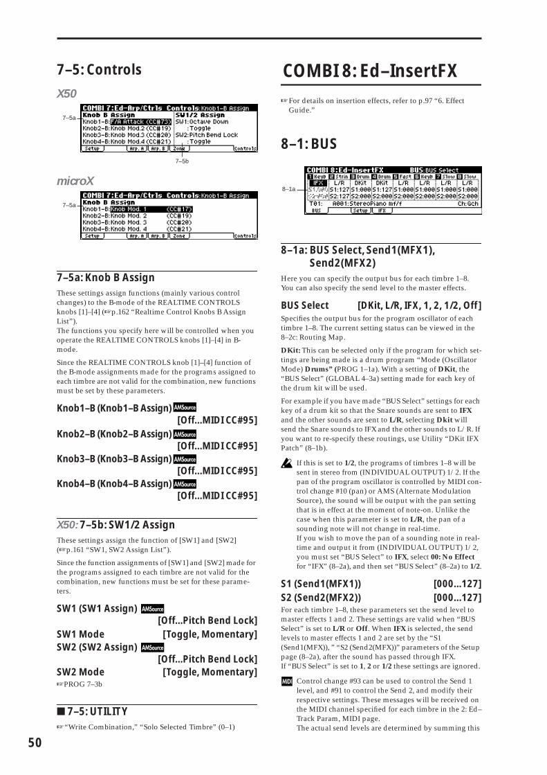
50
7–5: Controls
X50
microX
7–5a: Knob B AssignThese settings assign functions (mainly various control changes) to the B-mode of the REALTIME CONTROLS knobs [1]–[4] (☞p.162 “Realtime Control Knobs B Assign List”).The functions you specify here will be controlled when you operate the REALTIME CONTROLS knobs [1]–[4] in B-mode.
Since the REALTIME CONTROLS knob [1]–[4] function of the B-mode assignments made for the programs assigned to each timbre are not valid for the combination, new functions must be set by these parameters.
Knob1–B (Knob1–B Assign)[Off...MIDI CC#95]
Knob2–B (Knob2–B Assign)[Off...MIDI CC#95]
Knob3–B (Knob3–B Assign)[Off...MIDI CC#95]
Knob4–B (Knob4–B Assign)[Off...MIDI CC#95]
X50: 7–5b: SW1/2 AssignThese settings assign the function of [SW1] and [SW2] (☞p.161 “SW1, SW2 Assign List”).
Since the function assignments of [SW1] and [SW2] made for the programs assigned to each timbre are not valid for the combination, new functions must be set for these parame-ters.
SW1 (SW1 Assign) [Off...Pitch Bend Lock]
SW1 Mode [Toggle, Momentary]SW2 (SW2 Assign)
[Off...Pitch Bend Lock]SW2 Mode [Toggle, Momentary]☞PROG 7–3b
■ 7–5: UTILITY☞“Write Combination,” “Solo Selected Timbre” (0–1)
COMBI 8: Ed–InsertFX
☞For details on insertion effects, refer to p.97 “6. Effect Guide.”
8–1: BUS
8–1a: BUS Select, Send1(MFX1), Send2(MFX2)
Here you can specify the output bus for each timbre 1–8. You can also specify the send level to the master effects.
BUS Select [DKit, L/R, IFX, 1, 2, 1/2, Off]Specifies the output bus for the program oscillator of each timbre 1–8. The current setting status can be viewed in the 8–2c: Routing Map.
DKit: This can be selected only if the program for which set-tings are being made is a drum program “Mode (Oscillator Mode) Drums” (PROG 1–1a). With a setting of DKit, the “BUS Select” (GLOBAL 4–3a) setting made for each key of the drum kit will be used.
For example if you have made “BUS Select” settings for each key of a drum kit so that the Snare sounds are sent to IFX and the other sounds are sent to L/R, selecting Dkit will send the Snare sounds to IFX and the other sounds to L/R. If you want to re-specify these routings, use Utility “DKit IFX Patch” (8–1b).
If this is set to 1/2, the programs of timbres 1–8 will be sent in stereo from (INDIVIDUAL OUTPUT) 1/2. If the pan of the program oscillator is controlled by MIDI con-trol change #10 (pan) or AMS (Alternate Modulation Source), the sound will be output with the pan setting that is in effect at the moment of note-on. Unlike the case when this parameter is set to L/R, the pan of a sounding note will not change in real-time.If you wish to move the pan of a sounding note in real-time and output it from (INDIVIDUAL OUTPUT) 1/2, you must set “BUS Select” to IFX, select 00: No Effect for “IFX” (8–2a), and then set “BUS Select” (8–2a) to 1/2.
S1 (Send1(MFX1)) [000...127]S2 (Send2(MFX2)) [000...127]For each timbre 1–8, these parameters set the send level to master effects 1 and 2. These settings are valid when “BUS Select” is set to L/R or Off. When IFX is selected, the send levels to master effects 1 and 2 are set by the “S1 (Send1(MFX)), ” “S2 (Send2(MFX))” parameters of the Setup page (8–2a), after the sound has passed through IFX.If “BUS Select” is set to 1, 2 or 1/2 these settings are ignored.
Control change #93 can be used to control the Send 1 level, and #91 to control the Send 2, and modify their respective settings. These messages will be received on the MIDI channel specified for each timbre in the 2: Ed–Track Param, MIDI page.The actual send levels are determined by summing this
7–5a
7–5b
7–5a
8–1a

CO
MB
I0
12
34
56
78
9
value with the send level “S1 (Send1(MFX)), ” “S2 (Send2(MFX))” (PROG 8–2a) for each oscillator of the program selected for the timbre.
■ 8–1: UTILITY
☞“Write Combination,” “Solo Selected Timbre” (0–1)
Copy Insert Effect☞PROG 8–1
However, the MIDI control channel specified for “Con-trol Channel” of the 8: Ed–InsertFX, Setup page will not be copied.
DKit IFX Patch (DrumKit IFX Patch)This command changes the “BUS Select” settings for each key of the drum kit, so that connections to the IFX are tem-porarily changed to L/R. This can be executed only if the program specified for a timbre is a drum program, and the “BUS Select” (8–1a) setting is DKit, and the “BUS Select” (GLOBAL 4–3a) for each key of the drum kit is IFX.
1 Select “DKit IFX Patch” to access the dialog box.
2 At the right of “DrumKit IFX→,” select L/R as the patch destination.
3 To execute Drum Kit Insert Effect Patch, press the [MENU/OK] button. To cancel, press the [EXIT/CAN-CEL] button.To return the drum kit to its original state, execute IFX → IFX.
8–2: SetupHere you can select the type of insert effect, turn it on/off etc.
8–2a: Ed–InsertFX Setup
IFX On/Off [Off, On]Insert Effect [00...89: name]Pan(CC#8) [L000...C064...R127]BUS Select [L/R, 1, 2, 1/2, Off]S1 (Send1(MFX1)) [000...127]S2 (Send2(MFX2)) [000...127]These parameters are the same as in Program mode. (☞PROG 8–2)However, dynamic modulation (Dmod) of the insert effect
and the “Pan (CC#8), “Send1(MFX1),” and “Send2(MFX2)” that follow the insert effect will be controlled on the “Con-trol Channel” (8–2b) MIDI channel, unlike in Program mode. The control changes used are the same as in Program mode.
8–2b: Control Channel
Control Channel [Ch01...16, G ch, All Rt.]
Specifies the MIDI channel on which dynamic modula-tion (Dmod) of the insert effect and the “Pan (CC#8), “Send1(MFX1),” and “Send2(MFX2)” that follow the insert effect will be controlled.
The channel number of the timbre routed through this IFX will be followed by a “*” displayed at the right of Ch01–16. If two or more timbres with different MIDI channel settings are routed through the IFX, this parameter specifies which of these channels will be used to control the effect.
G ch: The global MIDI channel “MIDI Channel” (GLOBAL 1–1a) will be used to control the effect. Normally you will set this to G ch.All Rt. (All Routed): The channel of any timbre routed through this effect can be used to control the effect. (Chan-nels of each routed timbre will be indicated by “*”.)
If “BUS Select” (8–1a) is set to DKit for a timbre for which a drums program is selected, the MIDI channel of that timbre will be valid only if this is set to All Rt., regardless of the drum kit “BUS Select” setting (GLO-BAL 4–3a) or the Utility “DrumKit IFX Patch” (8–1b) setting.
8–2c: Routing Map, BUS SelectThis displays the bus to which the programs used by tim-bres 1–8 will be sent.
Routing MapThis displays the insert effect settings. The routing, the spec-ified effect name, and the on/off status are shown.
T01...8: BUS Sel [DKit, L/R, IFX, 1, 2, 1/2, Off]While viewing the map, you can specify the bus where each timbre 1–8 will be sent.Use the ClickPoint [√][®][π][†] to select the timbre, and use the [VALUE] dial to set “BUS Select” (8–1a).These settings can also be made in “BUS Select” (8–1a).
■ 8–2: UTILITY☞“Write Combination,” “Solo Selected Timbre” (0–1),
“Copy Insert Effect” (PROG 8–1), “Dkit IFX Patch” (8–1), “Select by Category” (PROG 8–2)
8–2a
8–2c
8–2b
51
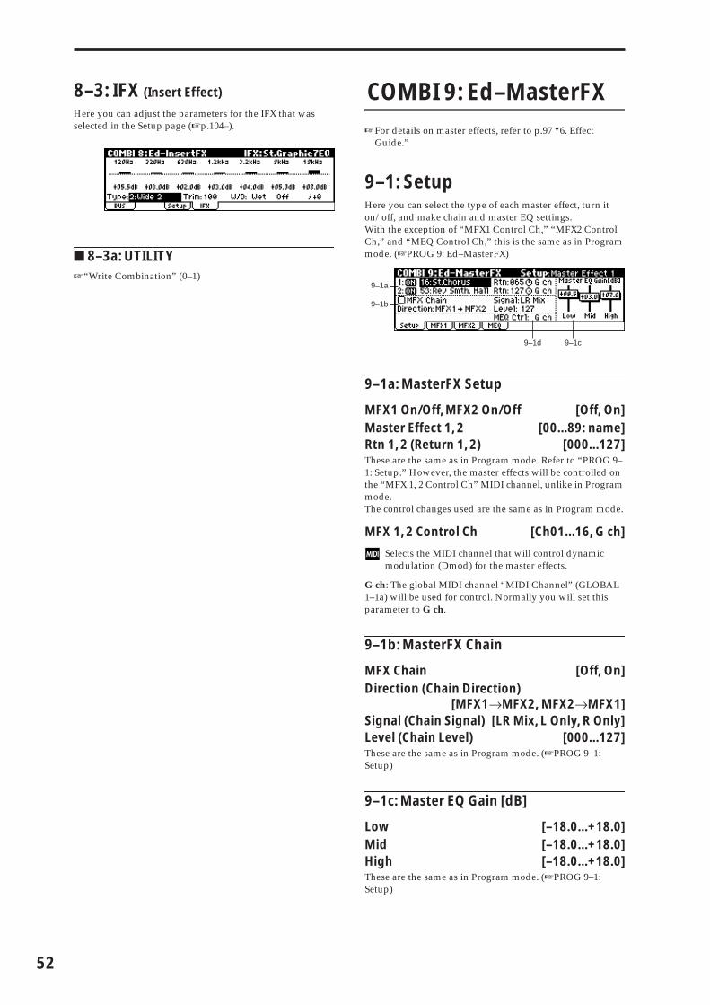
52
8–3: IFX (Insert Effect)
Here you can adjust the parameters for the IFX that was selected in the Setup page (☞p.104–).
■ 8–3a: UTILITY☞“Write Combination” (0–1)
COMBI 9: Ed–MasterFX
☞For details on master effects, refer to p.97 “6. Effect Guide.”
9–1: SetupHere you can select the type of each master effect, turn it on/off, and make chain and master EQ settings. With the exception of “MFX1 Control Ch,” “MFX2 Control Ch,” and “MEQ Control Ch,” this is the same as in Program mode. (☞PROG 9: Ed–MasterFX)
9–1a: MasterFX Setup
MFX1 On/Off, MFX2 On/Off [Off, On]Master Effect 1, 2 [00...89: name]Rtn 1, 2 (Return 1, 2) [000...127]These are the same as in Program mode. Refer to “PROG 9–1: Setup.” However, the master effects will be controlled on the “MFX 1, 2 Control Ch” MIDI channel, unlike in Program mode.The control changes used are the same as in Program mode.
MFX 1, 2 Control Ch [Ch01...16, G ch]
Selects the MIDI channel that will control dynamic modulation (Dmod) for the master effects.
G ch: The global MIDI channel “MIDI Channel” (GLOBAL 1–1a) will be used for control. Normally you will set this parameter to G ch.
9–1b: MasterFX Chain
MFX Chain [Off, On]Direction (Chain Direction)
[MFX1→MFX2, MFX2→MFX1]Signal (Chain Signal) [LR Mix, L Only, R Only]Level (Chain Level) [000...127]These are the same as in Program mode. (☞PROG 9–1: Setup)
9–1c: Master EQ Gain [dB]
Low [–18.0...+18.0]Mid [–18.0...+18.0]High [–18.0...+18.0]These are the same as in Program mode. (☞PROG 9–1: Setup)
9–1a
9–1b
9–1c9–1d

CO
MB
I0
12
34
56
78
9
9–1d: MEQ Ctrl
MEQ Ctrl (MEQ Control Ch) [Ch01...16, G ch]
Selects the MIDI channel that will control dynamic modulation (Dmod) for the master EQ.
G ch: The global MIDI channel “MIDI Channel” (GLOBAL 1–1a) will be used for control. Normally you will set this parameter to G ch.
■ 9–1: UTILITY
☞“Write Combination,” “Solo Selected Timbre” (0–1), “Select by Category” (PROG 9–1)
Copy Master Effect☞p.30 PROG 9–1
Note, the MIDI control channel that is specified by “MFX1, 2 Control Ch” (9–1a) will not be copied.
Swap Master Effect☞p.31 PROG 9–1
Note, the MIDI control channel that is specified by “MFX1, 2 Control Ch” (9–1a) will not be swapped.
9–2: MFX1 (Master Effect1)
9–3: MFX2 (Master Effect2)
Here you can set the parameters of the “Master Effect1” and “Master Effect2” effects that were selected in the Setup page (☞p.104–).
■ 9–2(3): UTILITY☞“Write Combination” (0–1)
9–4: MEQ (Master EQ)
The master EQ is a three-band stereo EQ. It is located imme-diately before the (MAIN OUTPUT) L/MONO and R from the L/R bus, and adjusts the overall tonal character of the sound (☞p.149). The MEQ High Gain and the MEQ Low Gain can be controlled by assigning a modulation source to the “Low Gain Mod-Src.” and “High Gain Mod-src.” func-tions on this page.
■ 9–4: UTILITY☞“Write Combination” (0–1)
53

54

3. Multi mode
MU
LTI
0 1
23
45
67
89
In Multi mode, the X50/microX functions as a 16-part multi-timbral MIDI tone generator that can receive and play multi-ple channels of MIDI messages from an external MIDI sequencer. You can also make the arpeggiator play in syn-chronization with an external MIDI sequencer.
A “Multi” has sixteen tracks for playing back musical data. You can assign a separate program and MIDI channel etc. to each track, so that multiple programs can sound simulta-neously.
MULTI PAGE MENU
For details on how to select pages in Multi mode, refer to p.1.
MULTI 0: Play
Here you can select multis, and make basic settings such as selecting the program used by each track.
0–1: MultiThis display shows the selected multi set, the track that will be played from the keyboard and the assignments made to the REALTIME CONTROLS.
X50
microX
0–1a: Multi Select, Control Track, (Tempo)
Multi Select [000…127: name]Here you can select the multi set that you wish to use.
X50: • Turn the [VALUE] dial.• Use the [INC][DEC] buttons.• Use the numeric buttons [0]–[9] to enter a program
number, and press the [ENTER] button to finalize the number.
• Press the center of the ClickPoint to highlight the field, then use [π][†] to select a program, and press the center to finalize your selection.
microX: • Turn the [VALUE] dial.• Press the center of the ClickPoint to highlight the field,
then use [π][†] to select a program, and press the center to finalize your selection.
If “Multi Mode” (GLOBAL 0–2a) is set to Master, when the multi set is changed, track whose “Status” is EXT, EX2 or BTH will transmit bank and program number via MIDI. If “Multi Mode” (GLOBAL 0–2a) is set to for Master, switching the multi set will transmit bank select, program change, volume, pan, portamento, send 1, 2, post IFX pan, and post IFX send 1 and 2 messages on the MIDI channel of the corresponding track for each track whose “Status” (2–1a/2a) is EXT, EX2, or BTH.
Play 0: Play Select multis. Select a program for each track, and make pan and level settings. microX: Select an external control set. (☞p.55)
Tone Adjust 1: Tone Adjust Select the program used by each track.Specify the pan and volume of each pro-gram.Use Tone Adjust to adjust parameters. (☞p.59)
Track Param 2: Track Param MIDI, voice mode, pitch, delay, and scale settings for each track. (☞p.61)
MIDI Filter1 3: MIDI Filter1 MIDI message transmission/reception filter settings for each track: Prog Change, After Touch, JS and Ribbon etc. (☞p.64)
MIDI Filter2 4: MIDI Filter2 Filter settings: Realtime Control Knob, SW, and Other Ctrl Change (☞p.65)
Key Zone 5: Key Zone Key zone settings for each track. (☞p.67)
Vel Zone 6: Vel Zone Velocity zone settings for each track. (☞p.68)
Arp/Controls 7: Arp/Ctrls Arpeggiator settings.Controller settings. (☞p.69)
Insert Effect 8: InsertFX Set BUS and master effect send level for each track. Insert effect routing, selection, and settings. (☞p.72)
Master Effect 9: MasterFX Master effect selection and settings. Mas-ter EQ settings. (☞p.73)
0–1a
0–1a
�
55

56
Control Track [T01…T16: name]This selects the track that will be played by the keyboard of the X50/microX and that will be controlled by the various controllers of the X50/microX.
Track names can be specified in Utility “Rename Track” (0–1).
When you play the keyboard or operate the controllers of the X50/microX, the internal sound generator will sound according to the settings (program, level, etc.) of the track you selected here (if its “Status” (2–1a/2a) is INT or BTH), and other tracks with the same MIDI channel will also sound at the same time (if their “Sta-tus” is INT or BTH). These messages will also be trans-mitted on the MIDI channel specified for these tracks (if their “Status” is EXT, EX2, or BTH).
� (Tempo) [040…240, EXT]This specifies the tempo of the arpeggiator.
040...240: This will be displayed if “MIDI Clock” (GLOBAL 1–1a) is Internal. The tempo you specify here will be used.EXT: This is shown if “MIDI Clock” is Ext-MIDI or Ext-USB (or if set to Auto and the X50/microX is operating as a slave). The internal tempo will synchronize to the MIDI clock being received from an external sequencer or other device.
You can also set this parameter from the 7: Arp/Ctrls, Setup page.
X50: You can set the tempo by tapping the [ENTER] button several times at the desired timing. Alternatively, if GLO-BAL 0–3: Foot page “Foot SW Assign” is set to Tap Tempo, you can specify the tempo by tapping your foot on a pedal switch connected to the ASSIGNABLE SWITCH jack.
microX: If GLOBAL 0–3: Foot page “Foot SW Assign” is set to Tap Tempo, you can specify the tempo by tapping your foot on a pedal switch connected to the ASSIGNABLE SWITCH jack.
Multi Information
X50: This area shows information about the selected multi set. This indicates the functions that are assigned to [SW1] and [SW2], and REALTIME CONTROLS B-mode [ASSIGN-ABLE 1–4] knobs.
microX: This area shows information about the selected multi set. This indicates the functions that are assigned to the REALTIME CONTROLS B-mode [ASSIGNABLE 1–4] knobs.
■ 0–1: UTILITY
For details on how to select the desired utility function, refer to “PROG 0–1: UTILITY.”
Write MultiIf you wish to save a multi set, be sure to write it into the memory of the X50/microX.An edited multi set cannot be recovered if you do not write it to memory before turning off the power or selecting another program.
For the procedure, refer to “Write Program” (PROG 0–1).
Copy From Combi (Copy from Combination)This command copies the parameters of the specified combi-nation to the currently selected multi set.
1 Select “Copy From Combi” to access the dialog box.
2 In “Combi,” select the copy source destination.
3 If you check “with Effects,” the insertion effect, master effect, and master EQ settings will also be copied.
4 In “To,” select the copy destination tracks (1–8 or 9–16).
5 If in step 4 you specified “To” as Track 1 to 8, the “Auto adjust Arpeggio Setting” option will be available. If you select this option, the MIDI channel and other settings of some tracks will be automatically adjusted and tracks will be added as necessary so that when you turn on the arpeggiator for the multi set, it will sound just like it did when you played the combination.
6 To execute the Copy From Combi command, press the [MENU/OK] button. To cancel, press the [EXIT/CAN-CEL] button. Be aware that when you execute this com-mand, the setting data of the currently selected multi will be erased, and overwritten by the data of the selected combination.

MU
LTI
0 1
23
45
67
89
GM InitializeThis command transmits a GM System On message to Multi mode, resetting all tracks to the GM settings (refer to the table below).
In Multi mode when a GM System On message is received from an external device or the tone generator will be reset to the GM settings in the same way as when this command is executed (However even in these cases, the parameters of the 9: MasterFX will not be reset).
Rename TrackSelects “Rename Track,” access the dialog box and rename the selected multi. Up to sixteen characters can be input. (☞OG X50: p.112, microX: p.114)
0–2: Prog..8 (Track Program T01...08)
0–3: Prog..16 (Track Program T09...16)
Indicates the program that will be used by each track.
0–2(3)a: Track Number & Category
Track Number & CategoryThis shows the track number and the abbreviated name of the program category.
0–2(3)b: Program Select
Program SelectX50: [A…D 000...127, G...g 001...128: name]microX: [A…E 000...127, G...g 001...128: name]In this area you can select the program that will be used by each track. The lower line shows part of the name of the pro-gram assigned to the track. For GM2 variation banks or the GM2 drums bank, the variation bank (1)–(9) or drums bank (d) will be shown.Choose this parameter, and use one of the following meth-ods to select a program.
X50: • Turn the [VALUE] dial.• Use the [INC][DEC] buttons.• Use the numeric buttons [0]–[9] to enter the program
number, and press the [ENTER] button to confirm.
GM Initialize Parameters
Parameter Track1–9, 11–16 Track10
0 Program Select G001:Acoustic Piano g(d)001:STANDARD Kit
Pan C064 C064
Volume 100 100
2 Status – – The setting remains unchanged
Use Program’s Scale – – The setting remains unchanged
7 Arpeggiator Assign – – The setting remains unchanged
Other Arpeggiator parameters – – The setting remains unchanged
8 IFX/Indiv.Out BUS Select L/R DKit
Send1(MFX1) 0 0
Send2(MFX2) 40 40
IFX1–5 – – The setting remains unchanged
Pan(CC#8) – – The setting remains unchanged
BUS Select – – The setting remains unchanged
Send1 – – The setting remains unchanged
Send2 – – The setting remains unchanged
Other Insert Effect parameters – – The setting remains unchanged
9 MFX1 – – 16: St. Chorus
MFX2 – – 53: Rev Smth. Hall
Return1 – – 127
Return2 – – 050
Other Master Effect and Master EQ parameters – – Default settings
0–2a
0–2b
0–2c
57

58
• Press the center of the ClickPoint to highlight the field in the display, use [π][†] to make your choice, and press the center to confirm.
• Use PROG BANK [A]–[GM] to select a bank (☞p.1)• Use “Select by Category” to choose from the desired
category (☞p.36)• Receiving a MIDI program change message can also be
used to select a program (☞p.171)
microX: • Turn the [VALUE] dial.• Press the center of the ClickPoint to highlight the field in
the display, use [π][†] to make your choice, and press the center to confirm.
• Use “Select by Category” to choose from the desired category (☞p.36)
• Receiving a MIDI program change message can also be used to select a program (☞p.171)
If the “Status” (2–1a/2a) is either INT or BTH, pro-grams can be selected by receiving MIDI program change messages. When the multi set is changed, X50/microX will transmit a song select message. Also, when a song select message is received from the specified source, the multi set will change. If the “Status” is EX2, a “–” will be displayed before the program number. Tracks whose “Status” is EX2 will transmit the bank number that was selected in the “Bank(EX2) LSB,” “Bank(EX2) MSB” (2–1a).
PLAY/MUTE [PLAY, MUTE]This specifies the play/muted status of each track.PLAY: The track will play.MUTE: The track will be muted (silent).
0–2(3)c: Selected Track Information
Selected Track InformationThis shows the currently selected track, program bank, number, name, and MIDI channel.
■ 0–2(3): UTILITY
☞“Write Multi,” “Copy From Combi,” “GM Initialize”(0–1)
For details on how to select the desired utility function, refer to “PROG 0–1: UTILITY.”
Select by CategoryYou can select the program for each track by category. This command can be selected when a Program page (Prog..8, Prog..16) is displayed.
☞PROG 0–1
0–4: Mix..8 (Mixer T01...08)
0–5: Mix..16 (Mixer T09...16)
Here you can set the pan and volume of each track.
0–4(5)a: Pan, Volume
Pan [RND, L001...C064...R127]Sets the pan of tracks 1–16.L001...C064...R127: A setting of L001 is far left, and R127 is far right. A setting of C064 will reproduce the pan setting of the oscillator in Program mode.
If a mono-type insertion effect is inserted, this setting will be ignored. In this case, the 8: InsertFX, Setup page “Pan (CC#8)” setting will adjust the pan of the sound following the insertion effect.
RND: The sound will be panned randomly at each note-on.
If “Status” (2–1a/2a) is INT or BTH, CC#10 Panpot can be received to control the panning. When receiving CC#10, a value of 0 or 1 is far left, 64 is center, and 127 is far right. If “Multi Mode” (GLOBAL 0–2a) is set to for Master, the pan setting you specify here will be trans-mitted via MIDI for tracks whose “Status” is EXT, EX2, or BTH when you switch the multi set number. (RND removes)
Volume [000...127]Sets the volume of tracks 1–16.
When “Status” (2–1a/2a) is INT or BTH, CC#7 Volume can be received to control the volume. The volume of a track is determined by multiplying the MIDI Volume (CC#7) and Expression (CC#11) values. If “Multi Mode” (GLOBAL 0–2a) is set to for Master, the volume setting you specify here will be transmitted via MIDI for tracks whose “Status” is EXT, EX2, or BTH when you switch the multi set number.
0–4a
OSC1: Amp1 Pan=L001OSC2: Amp2 Pan=R127
Left Center Right
Pan (CC#10)
C064
Left Center Right
L032
L001
R096
R127
Left Center Right
Left Center Right
OSC1 OSC2OSC1: Amp1 Pan=L032OSC2: Amp2 Pan=R096
Pan (CC#10)
C064
L032
L001
R096
R127
OSC1: Amp1 Pan=C064OSC2: Amp2 Pan=C064
Left Center Right
Pan (CC#10)
C064
Left Center Right
L032
L001
R096
R127
OSC1 OSC2

MU
LTI
0 1
23
45
67
89
■ 0–4(5): UTILITY☞“Write Multi,” “Copy From Combi,” “GM Initialize” (0–
1), “Select by Category” (0–2(3))
microX: 0–6: Ext. ControlThe external control function lets you use the REALTIME CONTROLS knobs to control an external MIDI device. You can assign a MIDI control change and MIDI channel to each of the four knobs, and switch between three such settings for each knob (A, B, C) to control your external device. One set lets you transmit a total of twelve (4 × 3) different MIDI con-trol changes. These are called “external control sets,” and you can choose from 64 such sets. (☞p.5)
This page only displays the settings of the external con-trol set you selected. Use Global mode to make external control assignments.
0–6a: External Control
Ext. Control (Setup Select) [00...63]Selects an external control set.
This setting is not written (saved) in the combination.
Select [A, B, C]Shows the settings assigned to each knob of the external control set. The currently-enabled set is highlighted. Use the [SELECT] button to switch between groups (A, B, C).
MIDI Channel [01...16, Gch]Indicates the MIDI channelGch: The message will be transmitted on the global MIDI channel you specify in Global mode. The channel of all knobs that are set to Gch can be changed simply by chang-ing the global MIDI channel setting, instead of having to change the channel of each knob individually.
CC# Assign [Off, 000...119]Indicates the MIDI control change number transmitted by the knob.
■ 0–6: UTILITY☞“Write Multi,” “Copy From Combi,” “GM Initialize” (0–
1), “Select by Category” (0–2(3))
MULTI 1: Tone Adjust
1–1: TA1..8 (Tone Adjust1)
1–2: TA1..16 (Tone Adjust1)
1–3: TA2..8 (Tone Adjust2)
1–4: TA2..16 (Tone Adjust2)
1–5: TA3..8 (Tone Adjust3)
1–6: TA3..16 (Tone Adjust3)
Here you can adjust certain synthesis parameters of the indi-vidual programs that are assigned to each track. These edits can be saved as part of the multi set.While creating a multi set, you might use this function to make a bass sound more mellow or to speed up the attack of a strings sound so that it fits better within a particular song, without having to return to Program mode and edit the pro-gram itself. For each track you can assign and adjust up to six parameters such as the filter cutoff, resonance, filter EQ, and amp EG.
1–1(2)(3)(4)(5)(6)a: Destination 1–6, Value 1–6
Destination 1–6 [LPF Fc…Reverse]Selects the parameter that you want to adjust.
Value 1–6 [–99…+99, –12.00…+12.00, –1200…+1200, Off…On]Specifies the value for the parameter you selected in “Desti-nation 1–6.” If you set this to +00 or PRG, the setting of the program will be used.
Normally, you should not select the same parameter for more than one “Destination” in the same track. How-ever if you do so, the parameters will operate as fol-lows.
If you select other than Hold or ReverseThe “Value” of each “Destination” set to the same parameter will be summed for each track. However, the “Value” of the parameter being controlled by the “Des-tination” will not exceed the allowable range of set-tings. For example if you have assigned three Detune1 settings for the same track, and their “Value” settings are set to +1000, +1000, and +1000 respectively, then the result will be +1200. (The sum is +3000, but the value is limited at the maximum of +1200 for the Detune1 parameter.) Settings of +1000, +1000, and –1000 would produce a result of +1000.
Hold, ReverseThe last of the multiple “Destination” settings will be valid.
0–6a
1–1a
59

60
“Destination 1–6” and “Value 1–6”The parameters that can be controlled and their range of val-ues are as follows.
LPF Fc (Low Pass Filter Cutoff Frequency)[–99…+00…+99]
Adjusts the low pass filter cutoff frequency of program OSC 1/2. This will affect the brightness of the sound. The param-eter will be controlled in the same way as when CC#74 is received. (☞p.175)
Reso.HP (Resonance/High Pass Filter Cutoff Frequency) [–99…+00…+99]Adjusts the resonance level of the low pass filter or the cut-off frequency of the high pass filter for program OSC 1/2. The parameter that is controlled will depend on the filter type specified for the program. The parameter will be con-trolled in the same way as when CC#71 is received. (☞p.175)
F EG Int (Filter EG Intensity) [–99…+00…+99]Adjusts the filter EG intensity (the depth of the filter EG) for program OSC1/2. The parameter will be controlled in the same way as when CC#79 is received. (☞p.175)
A Vel I. (Amp Velocity Intensity) [–99…+00…+99]Adjusts the amp velocity intensity (the degree to which velocity will affect the amp) for program OSC 1/2. This con-trols the Amp Modulation “Velocity Intensity” parameter (☞p.22 6–2b).
F.A EG A (Filter/Amp EG Attack Time)[–99…+00…+99]
Adjusts the EG attack times of the program OSC 1/2 filter and amp. To maximize the result of this adjustment, the Amp EG sustain level, attack level, start level modulation, and attack time modulation will also be adjusted at the same time. The parameter will be controlled in the same way as when CC#73 is received. (☞p.175)
F.A EG D (Filter/Amp EG Decay Time)[–99…+00…+99]
Adjusts the EG decay time and slope time of the program OSC 1/2 filter and amp. The parameter will be controlled in the same way as when CC#75 is received. (☞p.175)
F.A EG S (Filter/Amp EG Sustain Level)[–99…+00…+99]
Adjusts the EG sustain level of the program OSC 1/2 filter and amp. The parameter will be controlled in the same way as when CC#70 is received. (☞p.175)
F.A EG R (Filter/Amp EG Release Time)[–99…+00…+99]
Adjusts the EG release time of the program OSC 1/2 filter and amp. The parameter will be controlled in the same way as when CC#72 is received. (☞p.175)
F EG A (Filter EG Attack Time) [–99…+00…+99]F EG D (Filter EG Decay Time) [–99…+00…+99]F EG S (Filter EG Sustain Level) [–99…+00…+99]F EG R (Filter EG Release Time) [–99…+00…+99]These adjust only the filter parameter as in “A (Attack Time),” “D (Decay Time),” “S (Sustain Level),“ or “R (Release Time)” respectively. (☞PROG 4–5a)
A EG A (Amp EG Attack Time) [–99…+00…+99]A EG D (Amp EG Decay Time) [–99…+00…+99]A EG S (Amp EG Sustain Level) [–99…+00…+99]A EG R (Amp EG Release Time) [–99…+00…+99]These adjust only the amp parameter as in “A (Attack Time),” “D (Decay Time),” “S (Sustain Level),“ or “R (Release Time)” respectively. (☞PROG 6–3a, 6–6a)
LFO1 Sp (LFO1 Speed) [–199…+00…+199]Adjusts the LFO1 speed of program OSC 1/2. The parame-ter will be controlled in the same way as when CC#76 is received. (☞p.175)
PLFO1 I. (Pitch LFO1 Intensity)[–12.00…+00.00…+12.00]
Adjusts the program OSC 1/2 pitch LFO1 intensity (the depth of pitch modulation produced by LFO1). The parame-ter will be controlled in the same way as when CC#77 is received. (☞p.175)
LFO1 Fd (LFO1 Fade) [–99…+00…+99]Adjusts the program OSC 1/2 LFO1 “Fade” parameter (the time from when the LFO begins to take effect until it reaches the maximum level; 3–1a ☞p.14).
LFO1 Dl (LFO1 Delay) [–99…+00…+99]Adjusts the program OSC 1/2 pitch LFO1 delay (the time from note-on until the LFO begins to take effect). The parameter will be controlled in the same way as when CC#78 is received. (☞p.175)
P.Strch (Pitch Stretch) [–12…+00…+12]Simultaneously adjusts the program OSC 1/2 Transpose and Tune parameters. This lets you create a rich variety of tonal changes without impairing the character of the origi-nal sound.This controls the same parameters as Performance Editor - “Stretch (Pitch Stretch)” (0–2b). (☞p.4)
Dtune 1(Detune 1) [–1200…+0000…+1200]Adjusts the tuning of program OSC 1. This controls the OSC1 Multisample “Tune” parameter (1–2c ☞p.8).
Dtune 2 (Detune 2) [–1200…+0000…+1200]Adjusts the tuning of program OSC 2. This controls the OSC2 Multisample “Tune” parameter (1–2c ☞p.8).
This is valid only if the program’s “Oscillator Mode” (1–1a ☞p.6) is set to Double.
Hold [Off, PRG, On]Controls the program’s Voice Assign - “Hold” parameter (1–1b ☞p.6). If you turn this Off, the OSC1/2 Amp EG Release Time parameter will be set to 0 in order to make full use of the effect.Normally you can make effective use of this with a drum program. When you turn this Off, the key-off timing will be valid, letting you use the key-on/off timing to control the gate time. Sometimes you can obtain an interesting effect by turning this Off for a previously-created drum track.

MU
LTI
0 1
23
45
67
89
Reverse [Off, PRG, On]Controls the “Rev (Reverse)” parameter (1–1b ☞p.8, GLO-BAL 4–1b ☞p.87) for each Multisample or Drumsample of program OSC1/2.If you turn this On, all multisamples and drum samples will play backward. If you turn this Off, all multisamples and drum samples will play normally. If you set this to PRG, the settings of the program (or the drum kit used by the pro-gram) will be used. Normally you can make effective use of this with a drum program.
■ 1–1(2)(3)(4)(5)(6): UTILITY☞“Write Multi,” “Copy From Combi”(0–1)
MULTI 2: Track Param
2–1: MIDI..8 (MIDI T01–08)
2–2: MIDI..16 (MIDI T09–16)
Here you can make MIDI-related settings for each track.
2–1(2)a: Status, MIDI Channel, Bank(EX2) MSB/LSB
Status [INT, Off, BTH, EXT, EX2]This sets the status of MIDI and the internal tone generator for each track.
INT: The tone generator will sound in response to incoming MIDI messages from a connected external MIDI device. MIDI messages will not be transmitted. If the arpeggiator are assigned to a track that is set to INT, only the X50/microX will sound; MIDI data will not be transmitted to an external device (i.e., the external MIDI device will not sound). If the X50/microX’s controllers are operated on the track specified as the “Control Track” (0–1a), only the X50/microX will be controlled, and MIDI messages will not be transmitted.Off: The track will not sound, nor will MIDI data be trans-mitted.BTH: The operations of both INT and EXT will be per-formed. If the arpeggiator is specified for a track set to BTH, the X50/microX will sound and MIDI messages will also be transmitted. If the X50/microX’s controllers are operated on the track specified as the “Control Track” (0–1a), the X50/microX will be controlled and the same data will also be transmitted via MIDI.EXT: MIDI messages will be transmitted without sounding the track. If the arpeggiator are assigned to a track that is set to EXT, MIDI data will be transmitted to an external device, but the tone generator of the X50/microX will not sound. If the X50/microX’s controllers are operated on the track spec-ified as the “Control Track” (0–1a), MIDI messages will also be transmitted to control the external device, but the X50/microX itself will not be controlled.If “Multi Mode” (GLOBAL 0–2a) is set to for Master, the program change, volume, pan, portamento, send 1, 2, post IFX pan, and post IFX send 1, 2 settings for tracks set to EXT will be transmitted via MIDI.EX2: “Bank (EX2) MSB” and “Bank (EX2) LSB” will be enabled. Instead of the A–g(d) bank numbers that can be selected on the X50/microX, the bank number you specify here will be transmitted. In other respects this is the same as EXT.
MIDI data is transmitted and received on the MIDI channel that is specified separately for each track by “MIDI Channel.”
2–1a
61

62
MIDI Channel [01…16]Specifies the MIDI data that the track will use to transmit and receive MIDI data. Tracks set to INT which have the same MIDI channel will sound and be controlled identically when they receive MIDI data.
Bank(EX2) MSB [000...127]Bank(EX2) LSB [000...127]When “Status” is set to EX2, this sets the bank number that will be transmitted. When “Status” is other than EX2, this setting has no effect.
■ 2–1(2): UTILITY☞“Write Multi,” “Copy From Combi” (0–1)
2–3: OSC..8 (OSC T01–08)
2–4: OSC..16 (OSC T09–16)
Indicates settings for each track.
2–3(4)a: Force OSC Mode, OSC Select,Portamento
Force OSC Mode [PRG, Poly, Mono, LGT]Selects the “Mode (Voice Assign Mode)” (PROG 1–1b) of the program selected for each track 1–8, 9–16.(☞COMBI 2–2a)
OSC Select [Both, OSC1, OSC2]Specifies the “Mode (Oscillator Mode)” (PROG 1–1a) of the program selected for each track 1–8, 9–16. If the “Mode (Oscillator Mode)” is Double, you can use this setting to make only one or the other oscillator sound (☞COMBI 2–2a).
Portamento [PRG, Off, 001...127]Specifies the portamento effect for each track 1–8, 9–16.(☞COMBI 2–2a)
When the track whose “Status” (2–1a/2a) is INT or BTH, MIDI control change CC#05 (Portamento Time) and CC#65 (Portamento Switch) can be received to con-trol this and change the setting. (If the setting is PRG, CC#05 Portamento Time will not be received.)When you adjust these values, the settings will be transmitted via MIDI for tracks whose “Status” is BTH, EXT, or EX2. If “Multi Mode” (GLOBAL 0–2a) is set to for Master, these settings will be transmitted via MIDI
when you switch the multi set number. If this is Off, CC#65 with a value of 0 will be transmitted. If this is 001–127, a CC#65 of 127 and CC#05 of 001–127 will be transmitted.If this is set to PRG, nothing will be transmitted.
This data is transmitted on the MIDI channel specified for each track by “MIDI Channel” (2–1a/2a).
■ 2–3(4): UTILITY☞“Write Multi,” “Copy From Combi” (0–1)
2–5: Ptch..8 (Pitch T01–08)
2–6: Ptch..16 (Pitch T09–16)
Here you can make pitch-related settings for each track.
2–5(6)a: Transpose, Detune, Bend Range
Transpose [–24...+24]Adjusts the pitch of each track in semitone steps.12 steps are one octave.
Detune (BPM Adj.) [–1200... +1200]Adjusts the pitch of each track in one-cent steps from the normal pitch.0: Normal pitch.
You can use the Utility “Detune BPM Adj.” (2–5/6) to make a calculation in BPM units and set Detune auto-matically.
“Transpose” and “Detune” settings do not affect the note data that is transmitted via MIDI. “Transpose” and “Detune” are controlled by received MIDI RPN mes-sages. The “Mode (Oscillator Mode)” (PROG 1–1a) of the programs selected for tracks 1–16 will be controlled as follows.
• If “Mode (Oscillator Mode)” is Single or Double, MIDI RPN Coarse Tune messages can be received to control and change the “Transpose” setting, and Fine Tune messages to control and change the “Detune” setting.
• If “Mode (Oscillator Mode)” is Drums, MIDI RPN Coarse Tune and Fine Tune messages can be received to control and change the “Detune” setting. The range of control will be ±1 octave when Coarse Tune and Fine Tune are added. These messages will be received on the MIDI channel that is specified for each track by “MIDI Channel” (2–1a/2a).
Bend Range [PRG, –24...+24]Specifies the range of pitch change that will occur when the MIDI Pitch Bend Change message is received.
PRG: The pitch range specified by the program will be used.–24–+24: Regardless of the setting of the program, pitch bending will use the range you specify here.
Data from Arp.Operations on the X50/microX
Received data
Status Internal tone generator
MIDI OUT/USB
Internal tone generator
MIDI OUT/USB
INT ● × ● —
EXT, EX2 × ● × —
BTH ● ● ● —
2–3a
2–5a

MU
LTI
0 1
23
45
67
89
This setting can be controlled and changed by received MIDI RPN Pitch Bend Range messages. (These mes-sages will not be received if the setting is PRG.) This is controlled on the MIDI channel specified for each track by “MIDI Channel” (2–1a/2a).
■ 2–5(6): UTILITY
☞“Write Multi,” “Copy From Combi” (0–1)
For details on how to select the desired utility function, refer to “PROG 0–1: UTILITY.”
Detune BPM Adj. (Detune BPM Adjust)If a drum program uses a multisample to match a specific BPM, you can use this utility command to modify its BPM. “Detune BPM Adj.” changes the BPM of a phrase or rhythm by modifying its pitch.This command is available for a track if the track “Detune” parameter is selected. When you execute this command, the selected “Detune” value will be set automatically (☞PROG 1–2c, 1–3, GLOBAL 4–1b, 4–2). For the procedure, refer to “Detune BPM Adj.” (COMBI 2–3).
2–7: Othr..8 (Other T01–08)
2–8: Othr..16 (Other T09–16)
For each track, specify the delay time from note-on until the sound is heard, and select the scale.
2–7(8)a: Delay [ms] , Use Prog’s Scale
Delay [ms] [0000...5000, KeyOff]Specifies a delay time from when a track receives a note-on until it actually sounds.KeyOff: The sound will begin when note-off occurs. In this case, the sound will continue indefinitely unless the amp EG Sustain Level of the program is other than 0. This setting is useful for simulating harpsichord sounds.Normally you will leave this at 0.
Use Prog’s Scale [Off, On]Each track can use the scale that is specified for the program by “Scale” (PROG 1–1c).On (checked): The scale of the program will be used.Off (unchecked): The scale specified by “Type (Multi’s Scale)” (2–1b/2b) will be used.
2–7(8)b: ScaleSpecifies the scale that will be used for the multi.
Type (Multi’s Scale)[Equal Temperament...User Octave15]
Selects the type of scale.
☞“Type (Scale Type)” (PROG 1–1c)
Key [C…B]Selects the tonic key of the selected scale.
☞“Key” (PROG 1–1c)
Random [0…7]As this value is increased, an increasingly random devia-tion will be added to the pitch at each note-on.
☞“Random” (PROG 1–1c)
■ 2–7(8): UTILITY☞“Write Multi,” “Copy From Combi” (0–1)
2–7a
2–7b
63

64
MULTI 3: MIDI Filter1
Here you can select whether or not to apply filtering to the MIDI data received by tracks 1–16. For example, even if two tracks are receiving the same MIDI channels, one can be made to respond to damper pedal activity while the other does not.
These settings affect the MIDI messages that are trans-mitted when you adjust program, pan, volume, porta-mento and send 1/2 parameters of a track whose “Status” (2–1a/2a) is set to BTH, EXT, or EX2.
On (checked): Reception of MIDI data is enabled. Tracks whose “Status” (2–1a/2a) is INT or BTH will receive MIDI messages whose channel matches and whose types are checked. The types of effect that are checked will be applied to the program of each track when the X50/microX’s con-trollers are operated or when MIDI data is received. (The effect dynamic modulation function is not affected by these settings.) Settings that regulate MIDI transmission/recep-tion of the X50/microX itself are made in “MIDI Filter” (GLOBAL 1–1b).If MIDI control changes have been assigned as the function of the REALTIME CONTROLS knobs or of [SW1] and [SW2] (only X50), the MIDI filter for these controllers (MIDI Filter 2) will affect these control changes. However if these are the same as the control changes of MIDI Filter 1, the MIDI Filter 1, 2 settings will take priority. Furthermore, if the same con-trol change has been assigned to two or more controllers, checking any one of the MIDI Filter 2 parameters will cause the setting to apply to that control change.
Off (unchecked): Reception of MIDI data is disabled.
3–1: M1–1..8 (MIDI Filter1–1 T01–08)
3–2: 1–1..16 (MIDI Filter1–1 T09–16)
3–1(2)a: Program Change, After Touch
Program Change [Off, On]Specifies whether or not MIDI program change messages will be received.
After Touch [Off, On]Specifies whether or not MIDI after touch messages will be received.
■ 3–1(2): UTILITY☞“Write Multi,” “Copy From Combi” (0–1)
3–3: 1–2..8 (MIDI Filter1–2 T01–08)
3–4: 1–2..16 (MIDI Filter1–2 T09–16)
3–3(4)a: Damper CC#64, Portamento SW CC#65
Damper CC#64 [Off, On]Specifies whether or not MIDI control change message #64 Hold (damper pedal) will be received.
Portamento SW CC#65 [Off, On]Specifies whether or not MIDI control change message #65 Portamento On/Off will be received.
■ 3–3(4): UTILITY☞“Write Multi,” “Copy From Combi” (0–1)
3–5: 1–3..8 (MIDI Filter2–1 T01–08)
3–6: 1–3..16 (MIDI Filter2–1 T09–16)
3–5(6)a: JS+Y/M.Whl CC#01, JS–Y CC#02
JS+Y/M.Whl CC#01 [Off, On]
X50: Specifies whether MIDI control change CC#1 (the X50’s modulation wheel, or a REALTIME CONTROLS B-mode assignment) will be received.
microX: Specifies whether MIDI control change CC#1 (the +Y direction of the microX’s joystick or a REALTIME CON-TROLS B-assign setting) will be received.
JS–Y CC#02 [Off, On]
X50: Specifies whether MIDI control change CC#2 (REAL-TIME CONTROLS B-mode assignment, or the GLOBAL 0–3: Foot page “Foot Pedal Assign” set to JS –Y (CC#02) to spec-ify the function of a foot controller connected to the ASSIGNABLE PEDAL jack) will be received.
microX: Specifies whether MIDI control change CC#2 (the –Y direction of the microX’s joystick or a REALTIME CON-TROLS B-assign setting) will be received.
3–1a
3–3a
3–5a

MU
LTI
0 1
23
45
67
89
■ 3–5(6): UTILITY☞“Write Multi,” “Copy From Combi” (0–1)
3–7: 1–4..8 (MIDI Filter2–2 T01–08)
3–8: 1–4..16 (MIDI Filter2–2 T09–16)
3–7(8)a: JSX/PBend as AMS, Ribbon CC#16
JSX/PBend as AMS [Off, On]
X50: Specifies whether MIDI pitch bend messages (move-ment of the X50’s Pitch wheel) will apply the AMS (☞p.151 “Alternate Modulation Source”) assigned to Pitch Bend. (This is not a filter for MIDI pitch bend messages.)
microX: This parameter specifies whether the effect of the AMS (☞p.151 “Alternate Modulation Source”) assigned to JS X will be received when MIDI pitch bend messages (the X-axis) are received. (This is not a reception filter for MIDI pitch bend messages.)
Ribbon CC#16 [Off, On]MIDI control change message CC#16 (REALTIME CON-TROLS B-assign, or the assignment of a ribbon controller on a TRITON Extreme or other instrument connected to the MIDI IN connector) will be received.
■ 3–7(8): UTILITY☞“Write Multi,” “Copy From Combi” (0–1)
MULTI 4: MIDI Filter2
Specifies whether the A- and B-mode operations of REAL-TIME CONTROLS knobs [1]–[4] will be received. MIDI con-trol messages are fixed as the A-mode operation of each knob. In B-mode the knobs correspond to the messages you assign in the 7: Arp/Ctrls, Controls page.
X50: Specifies whether the effects of [SW1] and [SW2] will be received. The assignable switches [SW1] and [SW2] corre-spond to the messages that are assigned to the 7: Arp/Ctrls, Controls page.
4–1: M2–1..8 (MIDI Filter2–1 T01–08)
4–2: 2–1..16 (MIDI Filter2–1 T09–16)
4–1(2)a: Realtime Control Knob 1, 2
Knob1 [Off, On]Specifies whether or not the A-mode [1] knob MIDI control change message #74 (low pass filter cutoff frequency) and the B-mode [1] knob MIDI control change message will be received.
Knob2 [Off, On]Specifies whether or not the A-mode [2] knob MIDI control change message #71 (low pass filter resonance or high pass filter cutoff frequency) and the B-mode [2] knob MIDI con-trol change message will be received.
■ 4–1(2): UTILITY☞“Write Multi,” “Copy From Combi” (0–1)
3–7a
4–1a
65

66
4–3: 2–2..8 (MIDI Filter2–2 T01–08)
4–4: 2–2..16 (MIDI Filter2–2 T09–16)
4–3(4)a: Realtime Control Knob 3, 4
Knob3 [Off, On]Specifies whether or not the A-mode [3] knob MIDI control change message #79 (filter EG intensity) and the B-mode [3] knob MIDI control change message will be received.
Knob4 [Off, On]Specifies whether or not the A-mode [4] knob MIDI control change message #72 (the release time of the filter and amp EG’s) and the B-mode [4] knob MIDI control change mes-sage will be received.
■ 4–3(4): UTILITY☞“Write Multi,” “Copy From Combi” (0–1)
X50: 4–5: 2–3..8 (MIDI Filter2–3 T01–08)
X50: 4–6: 2–3..16 (MIDI Filter2–3 T09–16)
4–5(6)a: SW1, SW2
SW1, SW2 [Off, On]Specifies whether the operations of [SW1] and [SW2] will be received.These correspond to the control change messages assigned in the 7: Ed–Arp/Ctrls page. This setting is valid if you have selected SW1 Mod. (CC#80), SW2 Mod. (CC#81), or Porta.SW (CC#65).
■ 4–5(6): UTILITY☞“Write Multi,” “Copy From Combi” (0–1)
X50: 4–7: 2–4..8 (MIDI Filter2–4 T01–08)
microX: 4–5: 2–3..8 (MIDI Filter2–3 T01–08)
X50: 4–8: 2–4..16 (MIDI Filter2–4 T09–16)
microX: 4–6: 2–3..16 (MIDI Filter2–3 T09–16)
X50
microX
X50: 4–7(8)a/microX: 4–5(6)a: Foot Pedal/Switch, Other Control Change
Foot Pedal/Switch [Off, On]Specifies whether or not the effect of the ASSIGNABLE PEDAL/SWITCH will be received. The function of this switch is set in GLOBAL 0–3: System Foot page. This is valid when the switch is set to a MIDI control change.
Other Ctrl Change [Off, On]Specifies whether or not MIDI control change messages other than those included in MIDI Filter 1, 2 will be received.
■ X50: 4–7(8)/microX: 4–5(6): UTILITY☞“Write Multi,” “Copy From Combi” (0–1)
4–3a
4–5a
4–7a
4–5a

MU
LTI
0 1
23
45
67
89
MULTI 5: Key Zone
Here you can specify the range of keys that will be sounded by each track.Top/Bottom Key settings specify the range of notes that will be sounded by tracks 1–8, 9–16, and Top/Bottom Slope set-tings specify the range from the top/bottom key until the original volume is reached.
This setting does not affect MIDI transmission. All note data produced by the arpeggiator will be transmitted.
5–1: Key..8 (Key Zone T01–08)
5–2: Key..16 (Key Zone T09–16)
5–1(2)a: Key Zone Map (1)This shows the range of note data that will sound the cur-rently selected track. The note range that will be sounded is shown as a line, and the slope portion is grayed.
5–1(2)b: Top Key, Bottom Key
Top Key [C–1...G9]Specifies the top key (upper limit) that will be sounded by each track 1–8, 9–16.
Bottom Key [C–1...G9]Specifies the bottom key (lower limit) that will be sounded by each track 1–8, 9–16.
For a diagram of Key and Slope parameters, refer to “COMBI 5: Ed–Key Zone.”
X50: The value of these parameters can also be set by hold-ing down the [ENTER] button and playing a note on a con-nected MIDI instrument.
■ 5–1(2): UTILITY☞“Write Multi,” “Copy From Combi” (0–1)
5–3: Slp..8 (Key Slope T01–08)
5–4: Slp..16 (Key Slope T09–16)
5–3(4)a: Top Slope, Bottom Slope
Top Slope [00...72]Specifies the key range (12 is one octave) from the top key of track 1–8, 9–16 until the original volume is reached.
Bottom Slope [00...72]Specifies the key range (12 is one octave) from the bottom key of track 1–8, 9–16 until the original volume is reached. (☞p.46)
■ 5–3(4): UTILITY☞“Write Multi,” “Copy From Combi” (0–1)
5–5: Review
5–5a: Key Zone Map (All)
T1...T16This shows the range of note data that will be sounded by tracks 1–16. The note range that will be sounded is shown as a line, and the slope portion is grayed.
■ 5–5: UTILITY☞“Write Multi,” “Copy From Combi” (0–1)
5–1a
5–1b
5–3a
5–5a
67

68
MULTI 6: Vel Zone (Velocity Zone)
Specifies the range of velocities that will sound each track.Set the Top/Bottom Velocity parameters to set the range of velocities that will sound tracks 1–8 and 9–16, and set the Top/Bottom Slope parameters to specify the range over which the volume will change.
These settings do not affect MIDI transmission. All note data produced by the arpeggiator will be transmitted.
6–1: Vel..8 (Velocity Zone T01–08)
6–2: Vel..16 (Velocity Zone T09–16)
6–1(2)a: Velocity Zone Map (1)This shows the range of velocities that will sound the cur-rently selected track. The velocity range that will be sounded is shown as a line, and the slope portion is grayed.
6–1(2)b: Top Velocity, Bottom Velocity
Top Velocity [001…127]Specifies the maximum velocity that will be sounded by each track 1–8, 9–16.
Bottom Velocity [001…127]Specifies the minimum velocity that will be sounded by each track 1–8, 9–16.
It is not possible to set the bottom velocity greater than the top velocity for the same timbre. Nor can the top slope and the bottom slope overlap.
X50: The value of these parameters can also be set by hold-ing down the [ENTER] button and playing a note on a con-nected MIDI instrument.
■ 6–1(2): UTILITY☞“Write Multi,” “Copy From Combi” (0–1)
6–3: Slp..8 (Velocity Slope T01–08)
6–4: Slp..16 (Velocity Slope T09–16)
6–3(4)a: Top Slope, Bottom Slope
Top Slope [000…120]Specifies the range of values over which the volume will be adjusted from the top velocity until the original volume is reached.
Bottom Slope [000…120]Specifies the range of values over which the volume will be adjusted from the bottom velocity until the original volume is reached.
For a diagram of these parameters, refer to “COMBI 6: Ed–Vel Zone.”
■ 6–3(4): UTILITY☞“Write Multi,” “Copy From Combi” (0–1)
6–5: Review
6–5a: Velocity Zone Map (All)
T1...T16This shows the range of velocity that will be sounded by tracks 1–16. The note range that will be sounded is shown as a line, and the slope portion is grayed.
■ 6–5: UTILITY☞“Write Multi,” “Copy From Combi” (0–1)
6–1a
6–1b
6–3a
6–5a

MU
LTI
0 1
23
45
67
89
MULTI 7: Arp/Ctrls (Arpeggiator/Controls)
Here you can specify how the arpeggiator will operate in Multi mode. These settings can be made for each multi set. In Multi mode (as in Combination mode), you can run the two arpeggiators simultaneously.This allows you to apply different arpeggio patterns to two tracks, or use velocity to switch between two different arpeggio patterns, etc.
7–1: Set..8 (Setup T01–08)
7–2: Set..16 (Setup T09–16)
7–1(2)a: Arpeggiator Run, (Tempo)
Arpeggiator Run A, B (Run A, B)When the [ARP ON/OFF] button is on, the arpeggiator(s) that are checked here will function for the track(s) to which they are assigned by “Assign.” When the arpeggiator is on, A and B can be turned on/off independently.
� (Tempo) [040...240, (EXT)]Specify the tempo of the arpeggiator. This can also be adjusted by the REALTIME CONTROLS C-mode [TEMPO] knob.
☞p.56 “� (Tempo)” (0–1a)
7–1(2)b: Assign
Assign [Off, A, B]This assigns arpeggiator A or arpeggiator B to each track 1–8, 9–16. When the [ARP ON/OFF] button is turned on, the arpeggiator specified for each track will run, subject to the “Arpeggiator Run” settings and setting here.
Off: The arpeggiator will not operate.A: Arpeggiator A will operate. Use the Arp. A page to select the arpeggio pattern and set the parameters.B: Arpeggiator B will operate. Use the Arp. B page to select the arpeggio pattern and set the parameters.
If you wish to realtime-record the arpeggio pattern into a pattern, assign either arpeggiator A or B to the track.
If a track 1–16 to which arpeggiator A or B has been assigned is set to a track “Status” (2–1a/2a) of INT or BTH, the note data generated by the arpeggiator will sound the X50/microX without regard to the “MIDI Channel” (2–1a/2a) setting of each track. If the “Status” is BTH, EXT, or EX2, MIDI note data will be transmit-ted on the “MIDI Channel” of each track.
At this time, the arpeggiator can be triggered by the “MIDI Channel” of any track 1–16 assigned to arpeggiator A or B respectively.
The X50/microX’s arpeggiator can be controlled from an external sequencer, and the note data generated by the arpeggiator can be recorded on an external sequencer. (☞p.179)
Example 1)On tracks 1 and 2, set “MIDI Channel” (2–1(2)a) to 01 and “Status” (2–1(2)a) to INT. Assign arpeggiator A to track 1 and arpeggiator B to track 2, and check “Arpeggiator Run A, B” (7–1a). In “Control Track” (0–1a) choose Track01.With the front panel [ARP ON/OFF] button is off, play the keyboard and tracks 1 and 2 will sound simulta-neously.
When you turn on the front panel [ARP ON/OFF] button and play the keyboard, arpeggiator A will operate for track 1 and arpeggiator B will operate for track 2.
Example 2)For tracks 1, 2 and 3, set the “MIDI Channel” (2–1(2)a) to 01, 02, and 03 respectively, and set “Status” (2–1(2)a) to INT. Assign arpeggiator A to tracks 1 and 2, and arpeggiator B to track 3. Check the “Arpeggiator Run A, B” (7–1a) setting.
• In “Control Track” (0–1a), choose Track01.Playing the keyboard when the front panel [ARP ON/OFF] button is off will play the sound assigned to track 1.Playing the keyboard when the front panel [ARP ON/OFF] button is on will cause arpeggiator A to operate for tracks 1 and 2, and produce sound for both tracks.
• In “Control Track” (0–1a), choose Track02.Playing the keyboard when the front panel [ARP ON/OFF] button is off will play the sound assigned to track 2.Playing the keyboard when the front panel [ARP ON/OFF] button is on will cause arpeggiator A to operate for tracks 1 and 2, and produce sound for both tracks.
• In “Control Track” (0–1a), choose Track03.Playing the keyboard when the front panel [ARP ON/OFF] button is off will play the sound assigned to track 3.Playing the keyboard when the front panel [ARP ON/OFF] button is on will cause arpeggiator B to operate for track 3, and play the sound assigned to track 3.
• Alternatively, you could choose Track01 in “Control Track” (0–1a) to run arpeggiator A for tracks 1 and 2, and use an external MIDI device connected to the X50/microX’s MIDI IN to send note data to MIDI channel 3 to play arpeggiator B.
■ 7–1(2): UTILITY☞“Write Multi,” “Copy From Combi” (0–1), “Copy Arpeg-
giator” (COMBI 7–1)
7–1a
7–1b
�
Track2 MIDI Ch=1ch Status=INT
ArpeggiatorA
ArpeggiatorB
ArpeggiatorAssign
A
B
Pattern - A
Pattern - B
Pattern - A
Pattern - B
Trigger= Ch1
Trigger= Ch1
Track1 MIDI Ch=1ch Status=INT
Pattern - B
Pattern - A
Pattern - ATrack2 MIDI Ch=2ch Status=INT
ArpeggiatorA
ArpeggiatorB
ArpeggiatorAssign
A
A
Pattern - A
Pattern - B
Trigger= Ch1, Ch2
Trigger= Ch3
Track3 MIDI Ch=3ch Status=INTB
Track1 MIDI Ch=1ch Status=INT
69

70
7–3: Arp. A (Arpeggiator A)
7–4: Arp. B (Arpeggiator B)
Indicates settings for arpeggiator A in the Arp. A page, and for arpeggiator B in the Arp. B page.
You can use the “Copy Arpeggiator” utility to copy set-tings from another mode such as Program mode.
7–3(4)a: Arpeggiator–A (B) Setup
Pattern [Preset-0...Preset-4, U000...U250]Octave [1, 2, 3, 4]Reso (Resolution) [ � � , � , � � , � , � � , � ]Gate [000...100(%), Step]Velocity [001...127, Key, Step]Swing [–100...+100(%)]Sort [Off, On]Latch [Off, On]Key Sync. [Off, On]Keyboard [Off, On]These are the arpeggiator parameters for the multi set.(☞PROG 7: Ed–Arp/Ctrls)
■ 7–3(4): UTILITY☞“Write Multi,” “Copy From Combi” (0–1), “Copy Arpeg-
giator” (COMBI 7–1)
7–5: Zone (Scan Zone)
Specifies the range of notes and velocities that will trigger each arpeggiator A and B.
7–5a: Scan Zone A/B
Zone MapThis shows the “Scan Zone” settings for arpeggiators A and B (☞COMBI 7–4a).
A: KeyBtm (A-Bottom Key) [C–1...G9]Top (A-Top Key) [C–1...G9]Specifies the range of notes (keys) that will trigger arpeggiator A. “Top” is the upper limit, and “Btm” is the lower limit.
A: Vel (Velocity)Btm (A-Bottom Velocity) [001...127]Top (A-Top Velocity) [001...127]Specifies the range of velocities that will trigger arpeggiator A. “Top” is the upper limit, and “Btm” is the lower limit.
B: KeyBtm (B-Bottom Key) [C–1...G9]Top (B-Top Key) [C–1...G9]
B: Vel (Velocity)Btm (B-Bottom Velocity) [001...127]Top (B-Top Velocity) [001...127]Specifies the range of notes (keys) and velocities that will trigger arpeggiator B (☞“A: Key,” “A: Vel”).
X50: The value of these parameters can also be set by hold-ing down the [ENTER] button and playing a note on a con-nected MIDI instrument.
■ 7–5: UTILITY☞“Write Multi,” “Copy From Combi” (0–1), “Copy Arpeg-
giator” (COMBI 7–1)
7–3a
7–5a

MU
LTI
0 1
23
45
67
89
7–6: ControlsWhen you operate these controllers on the MIDI chan-nel of the “Control Track,” the MIDI messages assigned here will be transmitted (if “Status” 2–1a/2a is EXT, EX2, or BTH).
X50
microX
7–6a: Knob B AssignHere you can set the B-mode functions (mainly various con-trol changes) that the REALTIME CONTROLS knobs [1]–[4] will have (☞p.162 “Realtime Control Knobs B Assign List”).
When the REALTIME CONTROLS are in B-mode, the func-tions you specify here will be controlled on the track and MIDI channel of the “Control Track” (0–1a) when you oper-ate knobs [1]–[4].
The functions you specify here will operate when you rotate the REALTIME CONTROLS knobs [1]–[4] in B-mode.
Knob1–B (Knob1–B Assign)[Off…MIDI CC#95]
Knob2–B (Knob2–B Assign)[Off…MIDI CC#95]
Knob3–B (Knob3–B Assign)[Off…MIDI CC#95]
Knob4–B (Knob4–B Assign)[Off…MIDI CC#95]
X50: 7–6b: SW1/2 AssignAssigns functions to [SW1] and [SW2] (☞p.161 “SW1, SW2 Assign List”).Since the [SW1] and [SW2] function assignments of the pro-gram assigned to each track are ignored when the program is used in a multi, you must make new assignments here for the multi.
SW1 (SW1 Assign) [Off…Pitch Bend Lock]
SW1 Mode [Toggle, Momentary]SW2 (SW2 Assign)
[Off…Pitch Bend Lock]SW2 Mode [Toggle, Momentary]☞PROG 7–3b
■ 7–6: UTILITY☞“Write Multi,” “Copy From Combi” (0–1)
7–6a
7–6b
7–6a
71

72
MULTI 8: InsertFX
☞For details on insert effects, refer to p.97 “6. Effect Guide.”
8–1: BUS..8 (BUS T01...08)
8–2: BUS..16 (BUS T09...16)
Specifies the bus to which the program oscillator(s) of each track 1–8, 9–16 will be sent. You can also set the amount of signal that will be sent to the master effects.
8–1(2)a: BUS Select, Send1(MFX1), Send2(MFX2)
BUS Select [DKit, L/R, IFX, 1, 2, 1/2, Off]Specifies the output bus for the program oscillators of tracks 1–8 and 9–16.The state of the settings can be viewed in the Setup page.
☞COMBI 8–1a
S1 (Send1(MFX1)) [000...127]S2 (Send2(MFX2)) [000...127]Here you can adjust the send levels from tracks 1–8, 9–16 to master effects 1 and 2. This is valid when “BUS Select” is set either to L/R or Off. If IFX is selected, the send level to the master effects 1 and 2 is set by the (“S1 (Send1(MFX1))” and “S2 (Send2(MFX2))” parameters located in the Setup page, after the signal passes through IFX.These settings have no effect if “BUS Select” is set to 1, 2 or 1/2.
If “Status” (2–1(2)a) is either INT or BTH, CC#93 and #91 can be received to control send 1 and 2 respectively and change their settings. If “Multi Mode” (GLOBAL 0–2a) is set to for Master, and you switch the multi set number, these settings will be transmitted via MIDI for tracks whose “Status” is EXT, EX2, or BTH. The set-tings are transmitted and received on the MIDI channel specified for each track by the “MIDI Channel” (2–1a/2a) setting. The actual send level is determined by sum-ming the value of these parameters with the send level settings of the oscillator(s) of the program used by the track (“S1 (Send1(MFX1))” and “S2 (Send2(MFX2))” PROG 8–2a).
■ 8–1(2): UTILITY
☞“Write Multi” (0–1), “DKit IFX Patch” (COMBI 8–1)
Copy Insert Effect☞PROG 8–1
However, the MIDI control channel specified in “Con-trol Channel” of the 8: InsertFX, Setup page will not be copied.
8–3: SetupHere you can select the type of the insert effects, turn them on/off etc.
8–3a: Insert FX Setup
IFX1 [Off, On]Insert Effect [00...89: name]Chain [ (Off), (ON)]Pan(CC#8) [L000...C064...R127]BUS Select [L/R, 1, 2, 1/2, Off]S1 (Send1(MFX1)) [000...127]S2 (Send2(MFX2)) [000...127]These parameters are the same as in Program mode. (☞PROG 8–2)However, this differs from Program mode in that insert effect dynamic modulation (Dmod) and the “Pan (CC#8),” “Send1(MFX1),” and “Send2(MFX2)” which follow the insert effect are controlled on the MIDI channel specified by “Control Channel” (8–1b). The control changes used are the same as in Program mode.
If the “Status” (2–1(2)a) is INT or BTH, receiving CC#8, #93, or #91 will cause the post- insert effect pan and send 1/2 to be controlled, changing the settings. If “Multi Mode” (GLOBAL 0–2a) is set to for Master, and you switch the multi set number, these settings will be transmitted via MIDI on the “Control Channel” (8–1a) for tracks whose “Status” is BTH, EXT, or EX2.
8–1a
8–3c
8–3a
8–3b
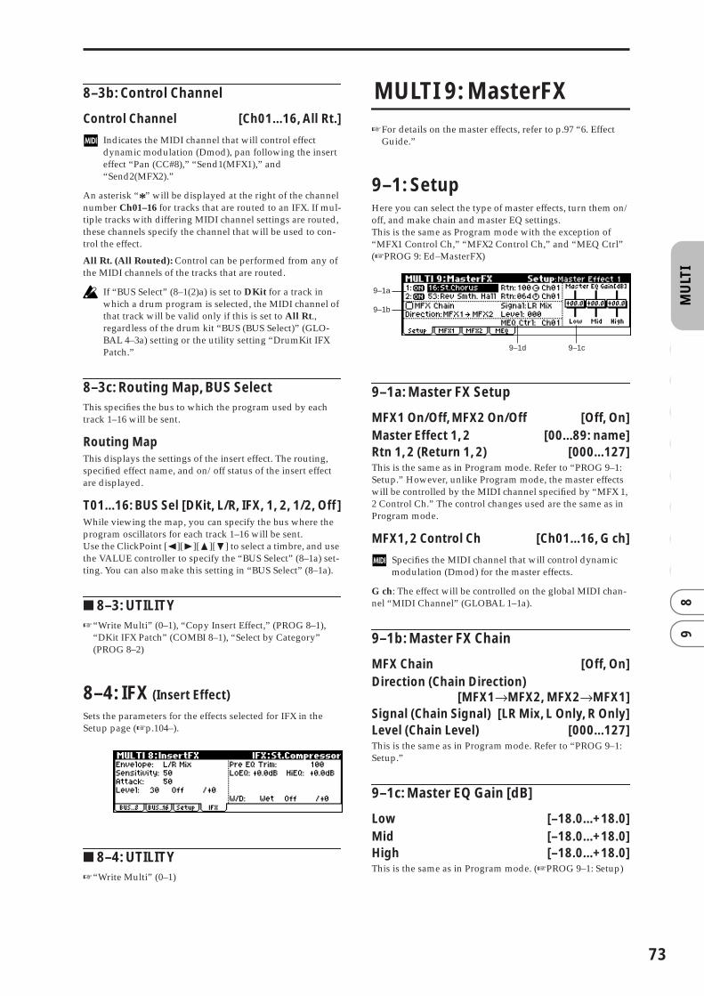
MU
LTI
0 1
23
45
67
89
8–3b: Control Channel
Control Channel [Ch01...16, All Rt.]
Indicates the MIDI channel that will control effect dynamic modulation (Dmod), pan following the insert effect “Pan (CC#8),” “Send1(MFX1),” and “Send2(MFX2).”
An asterisk “*” will be displayed at the right of the channel number Ch01–16 for tracks that are routed to an IFX. If mul-tiple tracks with differing MIDI channel settings are routed, these channels specify the channel that will be used to con-trol the effect.
All Rt. (All Routed): Control can be performed from any of the MIDI channels of the tracks that are routed.
If “BUS Select” (8–1(2)a) is set to DKit for a track in which a drum program is selected, the MIDI channel of that track will be valid only if this is set to All Rt., regardless of the drum kit “BUS (BUS Select)” (GLO-BAL 4–3a) setting or the utility setting “DrumKit IFX Patch.”
8–3c: Routing Map, BUS SelectThis specifies the bus to which the program used by each track 1–16 will be sent.
Routing MapThis displays the settings of the insert effect. The routing, specified effect name, and on/off status of the insert effect are displayed.
T01...16: BUS Sel [DKit, L/R, IFX, 1, 2, 1/2, Off]While viewing the map, you can specify the bus where the program oscillators for each track 1–16 will be sent.Use the ClickPoint [√][®][π][†] to select a timbre, and use the VALUE controller to specify the “BUS Select” (8–1a) set-ting. You can also make this setting in “BUS Select” (8–1a).
■ 8–3: UTILITY☞“Write Multi” (0–1), “Copy Insert Effect,” (PROG 8–1),
“DKit IFX Patch” (COMBI 8–1), “Select by Category” (PROG 8–2)
8–4: IFX (Insert Effect)
Sets the parameters for the effects selected for IFX in the Setup page (☞p.104–).
■ 8–4: UTILITY☞“Write Multi” (0–1)
MULTI 9: MasterFX
☞For details on the master effects, refer to p.97 “6. Effect Guide.”
9–1: SetupHere you can select the type of master effects, turn them on/off, and make chain and master EQ settings. This is the same as Program mode with the exception of “MFX1 Control Ch,” “MFX2 Control Ch,” and “MEQ Ctrl” (☞PROG 9: Ed–MasterFX)
9–1a: Master FX Setup
MFX1 On/Off, MFX2 On/Off [Off, On]Master Effect 1, 2 [00...89: name]Rtn 1, 2 (Return 1, 2) [000...127]This is the same as in Program mode. Refer to “PROG 9–1: Setup.” However, unlike Program mode, the master effects will be controlled by the MIDI channel specified by “MFX 1, 2 Control Ch.” The control changes used are the same as in Program mode.
MFX1, 2 Control Ch [Ch01...16, G ch]
Specifies the MIDI channel that will control dynamic modulation (Dmod) for the master effects.
G ch: The effect will be controlled on the global MIDI chan-nel “MIDI Channel” (GLOBAL 1–1a).
9–1b: Master FX Chain
MFX Chain [Off, On]Direction (Chain Direction)
[MFX1→MFX2, MFX2→MFX1]Signal (Chain Signal) [LR Mix, L Only, R Only]Level (Chain Level) [000...127]This is the same as in Program mode. Refer to “PROG 9–1: Setup.”
9–1c: Master EQ Gain [dB]
Low [–18.0...+18.0]Mid [–18.0...+18.0]High [–18.0...+18.0]This is the same as in Program mode. (☞PROG 9–1: Setup)
9–1a
9–1b
9–1c9–1d
73

74
9–1d: MEQ Ctrl
MEQ Ctrl (MEQ Control Ch) [Ch01...16, G ch]
Specifies the MIDI channel that will control dynamic modulation (Dmod) for the master EQ.
G ch: The effect will be controlled on the global MIDI chan-nel “MIDI Channel” (GLOBAL 1–1a).
■ 9–1: UTILITY
☞“Write Multi” (0–1), “Select by Category” (PROG 9–1)
Copy Master Effect☞p.30 PROG 9–1
Note, the MIDI control channel specified in “Control Channel” of the MFX 1 and 2 pages will not be copied.
Swap Master Effect☞p.31 PROG 9–1
Note, the MIDI control channel specified in “Control Channel” of the MFX 1 and 2 pages will not be swapped.
9–2: MFX1 (Master Effect1)
9–3: MFX2 (Master Effect2)
Here you can set the parameters of the “Master Effect1” and “Master Effect2” effects that were selected in the Setup page (☞p.104–).
■ 9–2(3): UTILITY☞“Write Multi” (0–1)
9–4: MEQ (Master EQ)
The master EQ is a three-band stereo EQ. It is used to per-form overall equalizing (tonal adjustment) on the sound from the L/R bus immediately before it is output to (MAIN OUTPUT) L/MONO and R (☞p.149).
■ 9–4: UTILITY☞“Write Multi” (0–1)

4. Global mode
GLO
BA
L0
12
34
56
In Global mode you can make settings that affect the entire instrument, such as master tuning, MIDI, and memory pro-tect.You can also edit user scales, drum kit setups, and user arpeggio patterns.
If you want the settings you make in Global mode to be backed up when the power is turned off, you must write them into memory. To write your settings, use the Utility “Write Global Setting,” “Write Drum Kits,” or “Write Arpeggio Patterns.”
GLOBAL PAGE MENU
For details on selecting pages and parameters, refer to Pro-gram mode “PROGRAM PAGE MENU” p.1.
X50
microX
GLOBAL 0: System
0–1: Basic
X50
microX
0–1a: Basic
Master Tune (Master Tune [Cent])[–50cent (427.47Hz)…+50cent (452.89Hz)]
This adjusts the overall tuning of this instrument in one-cent units (semitone = 100 cents) over a range of ±50 cents. With a setting of 0, the frequency of A4 will be 440 Hz.
The A4 pitch given here is when Equal Temperament is selected as the scale. If a different scale is selected, A4 may not be 440 Hz.
Key Transpose [–12…+12]his adjusts the pitch in semitone steps over a ±1 octave range.This setting is applied at the location (PreMIDI or Post-MIDI) specified by “Convert Position” (1–1a).
“Master Tune” can be controlled by the MIDI universal system exclusive message Master Fine Tuning (F0, 7F, nn, 04, 03, vv, mm, F7: nn=MIDI channel, vv/mm= value).“Key Transpose” can be controlled by the MIDI univer-sal system exclusive message Master Coarse Tuning (F0, 7F, nn, 04, 04, vv, mm, F7: nn=MIDI channel, vv/mm=value).These messages are received on the global MIDI chan-nel specified by “MIDI Channel” (1–1a).
System 0: System Basic settings for the entire X50/microX, and controller settings such as the pedals connected to the rear panel. (☞p.75)
MIDI 1: MIDI MIDI settings for this instrument. (☞p.81)
User Scale 2: User Scale Scale settings created by the user. You can specify 16 types of octave scale, and one full-range scale. (☞p.85)
Category Name 3: Category Name Edit category names for programs and combinations. (☞p.86)
DrumKit 4: DKit Edit drum kits. (☞p.86)
Arpeggio Pattern 5: Arp.Pattern Edit user arpeggio patterns. (☞p.89)
microX: Ext. Control 6: Ext Control External control settings. CC# assign-ments for the REALTIME CONTROLS knobs (☞p.93)
0–1a
0–1c0–1b
0–1a
0–1c0–1b
Note number transmitted
X5024…84
(C1…C6)
–12 0 +12
36…96(C2…C7)
48…108(C3…C8)
36…60(C2…C4)
48…72(C3…C5)
60…84(C4…C6)
Transpose
microX (when OCTAVE keys are dark)
75

76
In Program, Combination and Multi modes, MIDI RPN fine tuning messages can be received to adjust the tun-ing of the program, the timbres (in Combination mode), or the tracks (in Multi mode) relative to the Global mode “Master Tune” setting.In Program mode, MIDI RPN fine tune messages will be received on the global MIDI channel that you speci-fied for “MIDI Channel” (1–1a). In other modes, MIDI RPN fine tune messages will be received on the MIDI channel for each timbre (in Combination mode) or track (in Multi mode). (☞“Detune,” “Transpose”: COMBI 2–3a, MULTI 2–5(6)a.)
Velocity Curve [1…8]This specifies the way in which the volume and/or tone will change in response to how hard the keyboard is struck (velocity).When “Convert Position” (1–1a) is PreMIDI, variations in keyboard playing dynamics will affect the velocity effect and the transmitted velocity data as shown in the left-hand diagram on the following page. Incoming data will automat-ically use the velocity curve number 4 shown in the right-hand diagram.With a setting of PostMIDI, variations in keyboard playing dynamics and in the velocity of incoming data will create change as shown in the right-hand diagram on the below. If you are playing this instrument’s tone generator from an external keyboard or sequencer, and the overall sound is too bright or too dark, you can set the “Convert Position” parameter to PostMIDI and select the appropriate velocity curve here. For the transmitted data, the velocity curve number 4 shown in the left-hand diagram will automatically be selected.
1...3: These curves produce an effect for strongly-played notes.4(Normal): This is the standard curve.5, 6: An effect will be obtained even if you do not play very strongly7: A certain amount of effect will be obtained even for softly-played notes8: This curve produces the most regular effect. This setting is suitable when you do not need velocity sensitivity, or when you wish to make the notes more consistent. However with this curve, control of softly-played notes will be more diffi-cult, so use the curve that is most appropriate for your play-ing strength and style, and the effect that you wish to produce.The default factory setting for this parameter is 4.
microX: OCTAVE Keys [†/π]: Use Prog/Combi/Multi’s Octave [Off, On]On (checked): When you switch programs, combinations, or multi sets, the OCTAVE [†/π] button settings saved with the selected program, combination or multi set will be used.Off (unchecked): The OCTAVE [†/π] button settings will not change when you switch programs, combinations, or multi sets.
0–1b: FX SW
IFX Off [Off, On]On (checked): Insert effect IFX will be disabled.Off (unchecked): The Setup page (PROG/COMBI 8–2a, MULTI 8–3a) “IFX On/Off” setting of Program, Combina-tion, and Multi modes will be valid.
MFX1 Off [Off, On]On (checked): MFX1 will be disabled.Off (unchecked): The Master Effect Setup page (9–1) “MFX1 On/Off” settings of Program, Combination, and Multi mode will be valid.
MFX2 Off [Off, On]On (checked): MFX2 will be disabled.Off (unchecked): The Master Effect Setup page (9–1) “MFX2 On/Off” settings of Program, Combination, and Multi modes will be valid.
When “IFX On/Off,” or “MFX1 On/Off,” “MFX2 On/Off” settings are switched, control change messages CC#92 (effect control 2), CC#94 (effect control 4), and CC#95 (effect control 5) will be transmitted respectively. The transmitted data will be 0 for off, and 127 for on.
0–1c: Auto Arp. (Auto Arpeggiator)
Program (Auto Arp. Program) [Off, On]On (checked): When a different program is selected, the arpeggiator settings stored in that program will automati-cally take effect.Off (unchecked): The arpeggiator settings will not change when the program is switched. Use this setting when you wish to keep the same arpeggiator pattern running while you select different program sounds.
Combi (Auto Arp. Combi) [Off, On]On (checked): When a different combination is selected, the arpeggiator settings stored in that combination will auto-matically take effect.Off (unchecked): The arpeggiator settings will not change when the combination is switched. Use this setting when you wish to keep the same arpeggiator pattern running while you select different combination sounds.
■ 0–1: UTILITY
For details on how to select the desired utility function, refer to “PROG 0–1: UTILITY.”
Write Global SettingThis command writes Global mode settings (except for Drum Kits and User Arpeggio Patterns).
1 Select “Write Global Setting” to access the dialog box.
2 To write the data, press the [MENU/OK] button. To can-cel, press the [EXIT/CANCEL] button.
For a setting of PostMIDI
1
MAX
127
Velocity effect
Velocity (MIDI In→TG)
1
8
65
43
2
7
For a setting of PreMIDI
Soft
127
Strong1
Velocity (KBD→MIDI Out)
12
3
8
65
4
7

GLO
BA
L0
12
34
56
To write a drum kit or user arpeggio pattern, execute the appropriate utility. (☞4–1 “Write Drum Kits,” 5–1 “Write Arpeggio Patterns”)
Load Preload DataThis command loads the preload data into internal memory.
Before loading this data, you must uncheck the “Mem-ory Protect” (0–2b) setting for the data that you want to load. If the setting is still checked when you attempt to load the data, a dialog box will indicate “Memory Pro-tected,” and it will not be possible to load the data.
1 Select “Load Preload Data,” and access the dialog box.
2 In the “Kind” field, select the data that you want to load.
If you selected Program or Combination, move the cur-sor down and select All, Bank, or Single to specify the range of data that will be loaded.All: Data for all programs or combinations will be loaded.Bank: Data will be loaded in units of one bank. In this case, move the cursor down and select the bank whose data you want to load.Single: Data for one program or combination will be loaded. In this case, move the cursor down to select the data that you want to load.If you selected Multi DrumKit or Arpeggio Pattern, move the cursor down and select either All or Single to specify the range of data that will be loaded.
microX: You can also choose either All or Single even if you selected Ext. Control Setup.
All: Data for all multi set, drum kits or arpeggio patterns will be loaded.Single: Data for one multi set, drum kit or arpeggio pat-tern will be loaded. In this case, move the cursor down to select the data that you want to load.
3 If you are loading in units of Bank or Single, use the “To” field to select the loading destination.
4 To load the data, press the [MENU/OK] button. To can-cel, press the [EXIT/CANCEL] button.
If you turn on the power while holding down the [MENU/OK] button and the [EXIT/CANCEL] button, the “Load All” operation will be executed automati-cally (the LCD will display a message of “Now Writing Internal Memory”), and all data be loaded.
Change all bank referencesThis command changes all program banks specified for tim-bres in combinations or tracks of multi sets.
1 Select “Change all bank references” to access the dialog box.
X50
microX
2 To execute this command for combinations, check “Com-bination.” To execute this command for multi sets, check “Multi.”
3 Specify the banks to be changed (“Program Bank”).
4 To execute the Change All Bank References command, press the [MENU/OK] button. To cancel, press the [EXIT/CANCEL] button.
If you change two or more different banks to the same bank, it will not be possible to use this function to change them back to different banks. Be careful that the change destination banks do not overlap.
Half Damper CalibrationIf a damper pedal that supports half damper (the separately sold DS–1H option) is connected to the rear panel DAMPER jack, here’s how you can adjust the sensitivity if the damper effect is not applied appropriately.
1 Connect the half damper pedal to the DAMPER jack.
2 Select “Half Damper Calibration” to access the dialog box.
3 Press the half damper pedal, and then release the pedal.
4 Press the [MENU/OK] button.If the adjustment could not be performed correctly, an error message will appear. Please repeat the procedure.
Since the operation of the half damper pedal is delicate, please use the separately sold DS–1H option. If any other pedal is used, the correct effect may not be obtained, or adjustment may not be possible.
All All data
Program All All program data
Program Bank All program data of a bank
Program Single Data for one selected program
Combination All All combination data
Combination Bank All combination data of a bank
Combination Single Data for one selected combination
Multi All Data for all multi sets
Multi Single Data for one selected multi set
DrumKit All All drum kit data
DrumKit Single Data for one selected drum kit
Arpeggio Pattern All All arpeggio pattern data
Arpeggio Pattern Single Data for one selected arpeggio pattern
microX: Ext. Control Setup All Data for all external control sets
microX: Ext. Control Setup Single Data for one selected external control set
Global Setting Global setting data
77

78
0–2: Pref. (System Preference)
X50
microX
0–2a: System Preference
Multi Mode [for Ext-Seq, for Master]This specifies how MIDI data will be transmitted in Multi mode.for Ext-Seq: Normally, you will use Multi mode when using this instrument as a multi-timbral sound module with an external MIDI sequencer. In this case we recommend that you choose “for Ext-Seq.” When you switch multi sets on the X50/microX, program change and other MIDI messages will not be transmitted even for tracks that are set to EXT or BTH. This prevents echo-back from the tracks of your exter-nal MIDI sequencer from changing the program and other settings of tracks that are set to the same MIDI channel.for Master: Use this setting if you’re using this instrument in Multi mode as a master keyboard to control an external MIDI sound module. When you switch multi sets on the X50/microX, program change and other MIDI messages for tracks set to EXT or BTH will be transmitted to set up your external MIDI sound module. If you’re using the X50/microX as a master keyboard, you’ll normally use Combina-tion mode, but we recommend that you use this setting if you’re using Multi mode to control an external MIDI sound module.
When you switch multi sets, MIDI messages for the follow-ing parameters will be transmitted from tracks set to EXT or BTH.
• “Program Select” (MULTI 0–2(3)b): CC#00 bank select (LSB), CC#32 bank select (MSB), program change
• “Pan” (MULTI 0–4(5)a): CC#10 pan• “Volume” (MULTI 0–4(5)a): CC#7 volume• “Portamento” (MULTI 2–3(4)a): CC#65 portamento on/
off, CC#5 portamento time• “Send 1/2 (MULTI 8–1(2)a, 8–3a): CC#93 send level,
CC#91 send 2 level• Pan (CC#8) (8–3a): CC#8 post insert effect pan
Bank Map [KORG, GM]Specifies the mapping of programs and combinations rela-tive to Bank Select control change messages (CC#0 upper byte and CC#32 lower byte).
X50: The bank select messages shown in the following table can be received (R) or transmitted (T), corresponding to Program banks A...D, banks G, g(d) and Combination banks A...C.
Value: decimal, R: Receive, T: Transmit
microX: The bank select messages shown in the following table can be received (R) or transmitted (T), corresponding to Program banks A...E, banks G, g(d) and Combination banks A...C.
Value: decimal, R: Receive, T: Transmit
Power On Mode [Reset, Memorize]Specifies the condition at power-on.Reset: This instrument will be in Combination mode COMBI 0: Play, and Combination A000 will be selected.Memorize: The location (mode and page) where you were when the power was last turned off, and the last-selected program or combination number will be selected.
The contents of any parameters that were being edited are not saved by this function. Before turning the power off, you must Write your edits.
Page Menu Style [Icon, List]In each mode, you can press the [MENU/OK] button to see a list of the pages (PAGE MENU) for that mode. Here’s how you can specify how this list will appear.Icon: The pages will appear as icons. Use the ClickPoint [√][®][π][†] to select the page you want to view, and press the center of the ClickPoint to access that page. The page you had selected immediately before accessing the PAGE MENU will be highlighted.
0–2a
0–2b
0–2a
0–2b
Bank Bank Map: KORG Bank Map: GM
Bank A 00. 00 R/T 63. 00 R/T
Bank B 00. 01 R/T 63. 01 R/T
Bank C 00. 02 R/T 63. 02 R/T
Bank D 00. 03 R/T 63. 03 R/T
Bank G 121. 00, 121. 01…09 R/T 121. 00, 121. 01…09 R/T
56. 00 R 56. 00 R00. 00, 00. 01...(XG) R00. 00, 01. 00...(GS) R
Bank g (d) 120. 00 R/T 120. 00 R/T
62. 00 R 62. 00 R
63. 127 R (→Korg MUTE)
Bank Bank Map: KORG Bank Map: GM
Bank A 00. 00 R/T 63. 00 R/T
Bank B 00. 01 R/T 63. 01 R/T
Bank C 00. 02 R/T 63. 02 R/T
Bank D 00. 03 R/T 63. 03 R/T
Bank E 00. 04 R/T 63. 04 R/T
Bank G 121. 00, 121. 01…09 R/T 121. 00, 121. 01…09 R/T
56. 00 R 56. 00 R00. 00, 00. 01...(XG) R00. 00, 01. 00...(GS) R
Bank g (d) 120. 00 R/T 120. 00 R/T
62. 00 R 62. 00 R
63. 127 R (→Korg MUTE)

GLO
BA
L0
12
34
56
X50
microX
List: The pages will appear as a tabbed list. Use the Click-Point [π][†] to select the page you want to view, use [®] to move to a tab ([√] to move to a page), and use [π][†] to select the tab you want to view. Then press the center of the ClickPoint to access that tab. The page you had selected immediately before accessing the PAGE menu will be high-lighted.
LCD Contrast [0…62]This sets the contrast of the LCD screen.Higher values will increase the contrast.
If because of the temperature or other reasons, the LCD screen is unreadable when the power is turned on, use the following procedure to adjust the contrast.
1 While holding down the [EXIT/CANCEL] button, press the [UTILITY] button. The [GLOBAL] button will blink, and the Global mode Update Global Setting dialog box will appear.
If you are unable to read the display, or if the Update Global Setting dialog box does not appear, check whether the [GLOBAL] button is blinking. If the [GLO-BAL] button is lit or dark, the X50/microX may be writ-ing data that was received from an external connected MIDI device, or may be responding to a request for out-put. If so, make sure that the X50/microX is not writing data from an external connected MIDI device or trans-mitting data in response to a request, or that any such operation has been completed. Then turn the power of the X50/microX off and on again, and repeat this proce-dure from step 1.
2 Use the [VALUE] dial to adjust the LCD contrast.
3 Press the [MENU/OK] button.The LCD contrast setting will be memorized.
Other global settings will also be memorized at this time.
0–2b: Memory Protect
This setting also applies to Load Preload Data (0–1). Loading will not be possible if protect is specified for even one of the types of data selected for loading in “Kind” (☞p.77).
Program [Off, On]This setting protects the internal program memory.
On (checked): Internal program memory will be protected, and the following write operations cannot be performed.
• Writing a program
• Receiving program data via MIDI data dump
Off (unchecked): Data can be written to internal program memory.
Combi (Combination) [Off, On]This setting protects the internal combination memory.
On (checked): Internal combination memory will be pro-tected, and the following write operations cannot be per-formed.
• Writing a combination
• Receiving combination data via MIDI data dump
Off (unchecked): Data can be written to internal combina-tion memory.
Multi [Off, On]This setting protects the internal multi set memory.
On (checked): Internal multi set memory will be protected, and the following write operations cannot be performed.
• Writing to the a multi set
• Receiving multi set data via MIDI data dump
Off (unchecked): Data can be written to internal multi set memory.
Drum Kit [Off, On]This setting protects the internal drum kit memory.
On (checked): Internal drum kit memory will be protected, and the following write operations cannot be performed.
• Writing a drum kit
• Receiving drum kit data via MIDI data dump
Off (unchecked): Data can be written to internal drum kit memory.
Arp. UsrPat (Arp. User Pattern) [Off, On]This setting protects the internal user arpeggio pattern memory.
On (checked): Internal user arpeggio pattern memory will be protected, and the following write operations cannot be performed.
• Writing a user arpeggio pattern
• Receiving user arpeggio pattern data via MIDI data dump
Off (unchecked): Data can be written to internal user arpeg-gio pattern memory.
79
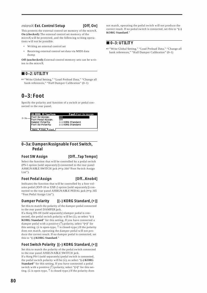
80
microX: Ext. Control Setup [Off, On]This protects the external control set memory of the microX.On (checked): The external control set memory of the microX will be protected, and the following writing opera-tions will not be possible.
• Writing an external control set
• Receiving external control set data via MIDI data dump
Off (unchecked): External control memory sets can be writ-ten to the microX.
■ 0–2: UTILITY☞“Write Global Setting,” “Load Preload Data,” “Change all
bank references,” “Half Damper Calibration” (0–1)
0–3: FootSpecify the polarity and function of a switch or pedal con-nected to the rear panel.
0–3a: Damper/Assignable Foot Switch, Pedal
Foot SW Assign [Off...Tap Tempo]Select the function that will be controlled by a pedal switch (PS-1 option [sold separately]) connected to the rear panel ASSIGNABLE SWITCH jack (☞p.164 “Foot Switch Assign List”).
Foot Pedal Assign [Off...Knob4]Indicates the function that will be controlled by a foot vol-ume pedal (XVP-10 or EXP-2 option [sold separately]) con-nected to the rear panel ASSIGNABLE PEDAL jack (☞p.165 “Foot Pedal Assign List”).
Damper Polarity [(–) KORG Standard, (+)]Set this to match the polarity of the damper pedal connected to the rear panel DAMPER jack.If a Korg DS-1H (sold separately) damper pedal is con-nected, the pedal switch polarity will be (↓), so select “(–) KORG Standard” for this setting. If you have connected a damper pedal with a positive (↑) polarity, select “(+)” for this setting. (↓ is open-type, ↑ is closed-type.) If the polarity does not match, operating the damper pedal will not pro-duce the correct result. If no damper pedal is connected, set this to “(–) KORG Standard.”
Foot Switch Polarity [(–) KORG Standard, (+)]Set this to match the polarity of the pedal switch connected to the rear panel ASSIGNABLE SWITCH jack.If a Korg PS-1 (sold separately) pedal switch is connected, the pedal switch polarity will be (↓), so select “(–) KORG Standard” for this setting. If you have connected a pedal switch with a positive (↑) polarity, select “(+)” for this set-ting. (↓ is open-type, ↑ is closed-type.) If the polarity does
not match, operating the pedal switch will not produce the correct result. If no pedal switch is connected, set this to “(–) KORG Standard.”
■ 0–3: UTILITY☞“Write Global Setting,” “Load Preload Data,” “Change all
bank references,” “Half Damper Calibration” (0–1)
0–3a

GLO
BA
L0
12
34
56
GLOBAL 1: MIDI
1–1: MIDIHere you can make MIDI-related settings that affect this instrument.
1–1a: MIDI Setup
MIDI Channel [01…16] Sets the global MIDI channel.
The global MIDI channel is used in the following cases.
• When transmitting and receiving performance data in Program mode (PROG 0: Play).
• When selecting combinations via MIDI in Combination mode (COMBI 0: Play).
• When controlling timbres or effects that have been set to Gch in various modes
• When transmitting and receiving system exclusive messages
About MIDI receptionIn Program mode (PROG 0: Play), MIDI data is received on the global MIDI channel, but in Combination mode (COMBI 0: Play) or Multi mode, MIDI data is received on the MIDI channel specified for each timbre or track.
In Combination mode (COMBI 0: Play) and Multi mode (MULTI 0: Play), program changes received on the global MIDI channel will switch the combination or multi set.
Use the global MIDI channel to switch IFX , MFX1 and MFX2 on/off.
To control the pan following IFX, sends 1/2, MFX 1/2 and MEQ, use the global MIDI channel in Program mode; in Combination, or Multi mode, use the channel specified sep-arately by “Control Channel” for IFX, MFX1, MFX2, and MEQ. By setting “Control Channel” to Gch, you can control these parameters from the global MIDI channel.
MIDI transmission when this instrument’s controllers are operatedIn Program mode, this data will be transmitted on the global MIDI channel. In Combination mode, data will be transmit-ted simultaneously on the global MIDI channel and on the MIDI channels of timbres whose “Status” (COMBI 2–1) is set to EXT or EX2.In Multi mode, musical data will be transmitted on the chan-nel of the track (“Status” BTH, EXT, or EX2) specified by “Control Track” (MULTI 0–1).
Note Receive [All, Even, Odd]This setting specifies which of the note messages played on this instrument’s keyboard or received via MIDI will be sounded. If you connect another X50/microX unit to this instrument in order to increase the total polyphony, set one unit to Even and the other to Odd, and set both units to sound.
All: All note numbers will be received. Normally you will leave this set to All.Even: Even-numbered notes (C, D, E, F#, G#, A#) will sound.Odd: Odd-numbered notes (C#, D#, F, G, A, B) will sound.
This setting has no effect on the MIDI data that is received.
MIDI Clock [Internal, Ext-MIDI, Ext-USB, Auto]Set this parameter when you wish to synchronize an exter-nal MIDI device (sequencer or rhythm machine etc.) with the X50/microX’s internal arpeggiator.
Internal: The internal arpeggiator will synchronize to the X50/microX’s own internal clock.Select the Internal setting when using the X50/microX by itself, or when you want the X50/microX to be the master (controlling device) so that another connected external MIDI device will synchronize to the MIDI Clock messages trans-mitted from the X50/microX.Ext-MIDI: The arpeggiator of the X50/microX will synchro-nize to MIDI Clock messages transmitted from an external MIDI device connected to the MIDI IN connector.Ext-USB: The X50/microX will synchronize to the MIDI Clock messages transmitted by an external MIDI device con-nected to the USB connector, and the internal arpeggiator of the X50/microX will operate as a slave device.
Use the Ext-MIDI or Ext-USB setting when you are using this instrument as a slave (controlled device) that synchro-nizes to the MIDI Clock messages received from an external MIDI device. This instrument will respond to MIDI real-time messages (Start, Stop, Continue, Song Select, Song Position Pointer) from an external sequencer.
Auto: Normally, operation will be the same as Internal. If you choose this setting, and the X50/microX receives MIDI clock messages from an external device, it will automatically switch to the same operation as the Ext-MIDI or Ext-USB settings.
If you have chosen the Auto setting when using an external sequencer, the X50/microX will automatically switch to the same operation as Internal if the external sequencer is not transmitting MIDI clock.
If no new MIDI clock messages are received from the MIDI IN or USB connector for an interval of 500 ms after receiving MIDI clock, start, or continue messages, or if the X50/microX’s arpeggiator has been started without receiving MIDI clock, start, or continue mes-sages from the MIDI IN or USB connector, it will switch to the same operation as the Internal setting.
Audition playback will occur at the pre-specified tempo, regardless of the “MIDI Clock” setting.
1–1a
1–1bODD EVEN
Another X50/microX
MIDI OUTUSB MIDI IN
USB
81

82
RT (Realtime Command) [Off, On]Off (unchecked): MIDI common messages and realtime messages (Start, Stop, Continue, Song Select, Song Position Pointer) will not be received if “MIDI Clock” is set to Ext-MIDI or Ext-USB, or if it is set to Auto and MIDI clock mes-sages are being received from an external source. (Song select messages will be received.)
Use this setting if the X50/microX’s multi set parame-ters are being unnecessarily reset due to these messages being received from an external MIDI sequencer.
On (Checked): The above common messages (including Song Select) and realtime messages will be received.
This setting is not available if “MIDI Clock” is set to Internal.
Convert Position [PreMIDI, PostMIDI]This setting specifies the location at which the Transpose, and will be applied. This setting will affect the MIDI data that is transmitted and received.When using this instrument’s keyboard to play the internal tone generator, the Transpose, and Velocity Curve will always take effect regardless of this setting.
PreMIDI: Velocity Curve, and Transpose will be applied to the data that is transmitted from this instrument’s keyboard.This setting affects the data that is transmitted from the MIDI OUT connector or USB connector when you play the keyboard of the X50/microX. It does not affect the MIDI data received via MIDI IN.
PostMIDI: Velocity Curve, and Transpose will be applied to data before it enters the tone generator. This setting affects the data that is sent from MIDI IN to the tone generator of the X50/microX. It does not affect the data that is sent from the MIDI OUT connector or USB connector when you play the keyboard of the X50/microX.
Local Control On [Off, On]On (checked) Local Control On: The controller of this instrument will controls its internal tone generator.Off (unchecked) Local Control Off: The controller of this instrument will be disconnected from the internal tone gen-erator.This means that operating this instrument (using the key-board or controller) will not produce sound.Uncheck this setting if the echo-back from an external sequencer causes this instrument to sound in duplicate.
Even if this is unchecked, MIDI transmission and recep-tion will occur as usual. Note messages will be trans-mitted when you play the keyboard, and this instrument’s tone generator will sound when note mes-sages are received.
1–1b: MIDI Filter
Enable Program Change [Off, On]On (checked): Program changes will be transmitted and received.In Program mode (PROG 0: Play), the program will be switched when a program change message is received on the global MIDI channel specified by “MIDI Channel” (1–1a). When you switch programs, a program change message will be transmitted on the global MIDI channel.
In Combination mode (COMBI 0: Play), the combination will be switched when a program change message is received on the global MIDI channel. However, it is possible to set the “Combi (Combi Change)” parameter so that the combination is not switched. When a program change is received on the channel specified for each timbre by “MIDI Channel” (COMBI 2–1a), the program of that timbre will be switched. However, the program changes for each timbre will be affected by the setting of the “Program Change” parameter (COMBI 3–1a).When you switch combinations, a program change message will be transmitted on the global MIDI channel, and also transmitted simultaneously on the channel of timbres whose “Status” (COMBI 2–1a) is set to EXT or EX2.
In Multi mode, incoming program change messages on a channel that corresponds to a track whose “Status” (MULTI 2–1(2)a) is set to INT or BTH will switch programs on that track. When you select a multi set will be transmitted on the channels of tracks whose “Status” is set to BTH, EXT, or EX2.Off (unchecked): Program changes will not be transmitted or received.
Bank (Bank Change) [Off, On]On (checked): The Bank Select control change message will be transmitted together with program change messages. This is valid when “Enable Program Change” is checked.Off (unchecked): Bank Select messages will not be transmit-ted or received.
Combi (Combi Change) [Off, On]On (checked): When in COMBI 0: Play, an incoming pro-gram change message on the global MIDI channel set by “MIDI Channel” (1–1a) will switch combinations. This is valid when “Enable Program Change” is checked. An incoming program change on a channel other than the glo-bal MIDI channel will switch the program of any timbre that matches that MIDI channel.Off (unchecked): An incoming program change message on the global MIDI channel will switch the program of any tim-bre whose “MIDI Channel” (COMBI 2–1a) matches the glo-bal MIDI channel. The combination will not be switched.The program changes for each timbre will be affected by the setting of the “Program Change” parameter (COMBI 3–1a).
VelocityCurve
Tonegenerator
Note number change
MIDI IN
MIDI OUT
Transpose Scale
USB
USB
VelocityCurve
Tonegenerator
MIDI IN
USB
MIDI OUT
USB
TransposeScale
Pitch change
MIDI INUSB
MIDI OUTUSB
Arpeggiator
Localcontrol
OFF
ON
TriggerTone
generator

GLO
BA
L0
12
34
56
AfterT (After Touch) [Off, On]On (checked): MIDI after touch messages will be transmit-ted and received.Off (unchecked): MIDI after touch messages will neither be transmitted nor received.
This setting affects the operation when GLOBAL 0–3: Foot “Foot SW Assign” or “Foot Pedal Assign” is set to After Touch.
Ctrl Change (Control Change) [Off, On]On (checked): Control change messages will be transmitted and received.Off (unchecked): Control change messages will not be transmitted or received.
Exclusive [Off, On]On (checked): System exclusive data will be transmitted and received. Check this setting when you wish to use a connected computer etc. to edit this instrument, or vice versa.Off (unchecked): System exclusive data will neither be transmitted nor received. Normally you will leave this unchecked.However, system exclusive data will be transmitted and received while the page menu commands (“Dump Pro-gram”–”Dump All”) of this page are displayed.
■ 1–1: UTILITY
☞“Write Global Setting” (0–1)
For details on how to select the desired utility function, refer to “PROG 0–1: UTILITY.”
Dump ProgramDump CombinationDump MultiDump Drum KitDump Arpeggio PatternmicroX: Dump Ext. Control SetupDump Global SettingDump AllThese commands allow this instrument’s data to be trans-mitted to another connected X50/microX, MIDI data filer, or computer in the form of system exclusive data.Selects the data to be dumped from the Utility menu (see the table below) to access the dialog box.Select the bank and number of the data you want to dump, and then press the center of the ClickPoint.
Transmission
Do not touch this instrument’s switches or turn off the power while data is being transmitted.
Data dump transmission procedure
1 Connect this instrument to the device that will receive the data dump.If you’re using a computer that is able to receive MIDI exclusive messages, connect the computer’s USB connec-tor to the X50/microX’s USB connector. Alternatively, connect the MIDI IN connector of your computer’s MIDI interface to the X50/microX’s MIDI OUT connector (☞p.171).If you are using a MIDI data filter etc., connect this instrument’s MIDI OUT connector to the MIDI IN con-nector of the MIDI data filter.
Some USB-MIDI interface devices may not be able to transmit or receive the X50/microX’s MIDI exclusive messages.
2 Select GLOBAL 1: MIDI.
3 In the Utility menu, select the data that you wish to dump.Shown below the “Dump Program” screen.If you wish to dump all program data, set “Program” to All.If you wish to dump data for an individual bank, set “Program” to Bank, and specify the bank number below it. If you wish to dump data for an individual program, set “Program” to Single, and specify the program num-ber below it.
4 Use the “To” field to specify the output destination of the data.Choose MIDI OUT if you want to send the data from the MIDI OUT connector. Choose USB if you want to send the data from the USB connector.
5 Press the [MENU/OK] button to transmit the data.While the data is being transmitted, the display will indi-cate “Now transmitting data.”The data size and the time required for transmission will depend on the type of data.For the size and the time required to dump each type of data, refer to the table below.
Dump Program Programs of all banks, programs of the specified bank, one program
Dump Combination Combinations of all banks, combinations of the specified bank, one combination
Dump Multi All multi sets
Dump Drum Kit All drum kits, One drum kit
Dump Arpeggio Pattern All arpeggio patterns, One arpeggio pattern
microX: Dump Ext. Control Setup
All external control sets or one external con-trol set
Dump Global Global settings (except for the Drum Kits and User Arpeggio Patterns of Global mode)
Dump All All banks of programs + combinations + drum kits + arpeggio patterns + global set-tings
Type of data dumped Data size (kByte)
Time required (Sec)
Program AllX50 (A...D) 259.8 66.5
microX (A…E) 324.8 83.1
Program Bank 65.0 16.6
Program Single 0.5 0.1
Combination All 238.7 61.1
Combination Bank 79.6 20.4
Combination Single 0.6 0.2
Multi All 17.8.5 45.7
Multi Single 1.4 0.4
83

84
When you save data dumps from this instrument to a MIDI data filer, do not save multiple data dumps together. If this data is saved together, there will be insufficient time for this instrument to write each received portion into memory before the next portion of data arrives, so that it will be impossible to receive all of the data correctly.
Reception
Do not touch this instrument’s switches or turn off the power while data is being received.
Before receiving data, we recommend that you close the various dialog boxes, page menus, or utility com-mands.
After a data dump is received, this instrument will require up to 20 seconds to process the data and write it into memory. During this time, the display will indicate “Now writing into internal memory.” While this dis-play is shown, you must under no circumstances turn off the power of this instrument. If the power is turned off during this time, this instrument may fail to operate correctly when the power is turned on again. If this occurs, hold down the [EXIT/CANCEL] button and the [PAGE +] button while you turn on the power. How-ever when this is done, the contents of memory will be initialized.
Transmission and reception of MIDI data is also impos-sible during this time. When receiving multiple data dumps in succession, you must allow an interval between the transmission of each data dump. (☞refer to the table below)
Processing time for writing into memory
While this instrument is writing the data into memory, transmission of Active Sensing (FEh) messages from the MIDI OUT connector or USB connector will stop.
Data dump reception procedure1 Connect this instrument and the device that will receive
the data dump.If you’re using a computer that is able to transmit MIDI exclusive messages, connect the computer’s USB connec-tor to the X50/microX’s USB connector. Alternatively, connect the MIDI OUT connector of your computer’s MIDI interface to the X50/microX’s MIDI IN connector (☞p.171).If you are using a MIDI data filer, connect the MIDI OUT connector of the data filer to the MIDI IN connector of this instrument.
Some USB-MIDI interface devices may not be able to transmit or receive the X50/microX’s MIDI exclusive messages.
2 Set the MIDI channel of the MIDI device to match the global MIDI channel “MIDI Channel” (1–1a) of this instrument. If data that was previously transmitted to the MIDI device is now going to be received again by this instrument, set the global MIDI channel of this instru-ment to the same global MIDI channel setting that was used when transmitting the data.
To set the MIDI channel of the transmitting device, refer to the owner’s manual for that device.
3 Turn check the “Exclusive” setting (1–1b).
4 Transmit the data from the other device. For the proce-dure, refer to the owner’s manual for the device you are using. While the data is being received, the display will indicate “Now received MIDI data.”
Drum Kit All 188 48.1
Drum Kit Single 4.7 0.4
Arpeggio Pattern All 91.8 23.5
Arpeggio Pattern Single 0.4 0.1
microX: Ext. Control Setup All 2.9 0.8
microX: Ext. Control Setup Single 0.1 0.0
Global Setting 1.0 0.3
AllX50 957.8 245.2
microX 1025.6 262.6
Type of data dumpedProcessing time for writing into memory
X50 microX
All Approximately 3 seconds
Approximately 3 seconds
All Programs Approximately 2 seconds
Approximately 2 seconds
One Program Bank Less than 1second Less than 1second
All Combinations Approximately 1 second
Approximately 1 second
One Combination Bank Less than 1second Less than 1second
All Multi Less than 1second Less than 1second
One Multi Less than 1second Less than 1second
All Drum Kits Approximately 1 second
Approximately 1 second
All Arpeggio Patterns Less than 1second Less than 1second
microX: All Ext. Control Setup — Less than 1second
microX: 1 Ext. Control Setup — Less than 1second
Global Setting Less than 1second Less than 1second
Type of data dumped Data size (kByte)
Time required (Sec)
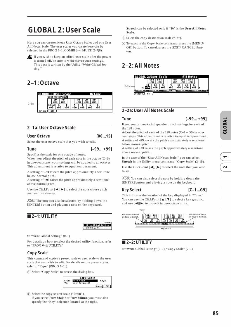
GLO
BA
L0
12
34
56
GLOBAL 2: User Scale
Here you can create sixteen User Octave Scales and one User All Notes Scale. The user scales you create here can be selected in the PROG 1–1, COMBI 2–4, MULTI 2–7(8).
If you wish to keep an edited user scale after the power is turned off, be sure to write (save) your settings.This data is written by the Utility “Write Global Set-ting.”
2–1: Octave
2–1a: User Octave Scale
User Octave [00...15]Select the user octave scale that you wish to edit.
Tune [–99…+99]Specifies the scale for one octave of notes.When you adjust the pitch of each note in the octave (C–B) in one-cent steps, your settings will be applied to all octaves. This adjustment is relative to equal temperament.
A setting of –99 lowers the pitch approximately a semitone below normal pitch.A setting of +99 raises the pitch approximately a semitone above normal pitch.
Use the ClickPoint [√][®] to select the note whose pitch you want to change.
X50: The note can also be selected by holding down the [ENTER] button and playing a note on the keyboard.
■ 2–1: UTILITY
☞“Write Global Setting” (0–1)
For details on how to select the desired utility function, refer to “PROG 0–1: UTILITY.”
Copy ScaleThis command copies a preset scale or user scale to the user scale that you wish to edit. For details on the preset scales, refer to “Type” (PROG 1–1c).
1 Select “Copy Scale” to access the dialog box.
2 Select the copy source scale (“From”).If you select Pure Major or Pure Minor, you must also specify the “Key” selection located at the right.
Stretch can be selected only if “To” is the User All Notes Scale.
3 Select the copy destination scale (“To”).
4 To execute the Copy Scale command press the [MENU/OK] button. To cancel, press the [EXIT/CANCEL] but-ton.
2–2: All Notes
2–2a: User All Notes Scale
Tune [–99…+99]Here, you can make independent pitch settings for each of the 128 notes.Adjust the pitch of each of the 128 notes (C–1 – G9) in one-cent steps. This adjustment is relative to equal temperament.A setting of –99 lowers the pitch approximately a semitone below normal pitch.A setting of +99 raises the pitch approximately a semitone above normal pitch.
In the case of the “User All Notes Scale,” you can select Stretch in the Utility menu command “Copy Scale” (2–1b).
Use the ClickPoint [√], [®] to select the note that you wish to set.
X50: You can also select the note by holding down the [ENTER] button and playing a note on the keyboard.
Key Select [C–1...G9]This indicates the location of the key displayed in “Tune.” You can use the ClickPoint [π][†] to select a key graphic, and use [√][®] to move it in one-octave units.
■ 2–2: UTILITY☞“Write Global Setting” (0–1), “Copy Scale” (2–1)
2–1a
2–2a
“Tune”
Indicates that there are keys to the left.
Indicates that there are keys to the right.
Key Select
85

86
GLOBAL 3: Category Name
3–1: P.0..7 (Prog.00...07)
3–2: P.8..15 (Prog.08...15)
3–3: C.0..7 (Comb.00...07)
3–4: C.8..15 (Comb.08...15)
Here you can rename the categories for programs and com-binations. Use the ClickPoint [√][®][π][†] to select the category you want to rename, press the center of the Click-Point to open the text dialog box, and enter the desired name. You can enter up to sixteen characters. (☞OG X50: p.112, microX: p.114).With the factory settings, these are classified by type of instrument.You can specify sixteen categories each for programs and combinations.
The category names you edit here can be specified when you write data in the “Write Program dialog box” (PROG 0–1: UTILITY) or “Write Combination dialog box” (COMBI 0–1: UTILITY), and used in the respective “Select by Category” function to select programs or combinations by category.
If you want the edited user categories to be backed up when the power is turned off, you must write them into memory. Select the Utility “Write Global Setting” to access the Write Global Setting dialog box and press the [MENU/OK] button to write the edited settings.
3–1 (...4)a: CategorySelect the category name you want to edit, and edit it.Use the ClickPoint [√][®][π][†] to select a category, press the center of the ClickPoint to open the text dialog box, and enter a category name of up to sixteen characters.For the editing procedure (☞OG X50: p.112, microX: p.114).
■ 3–1 (...4): UTILITY☞“Write Global Setting” (0–1)
GLOBAL 4: DKit (Drum Kit)
Here you can create a drum kit by assigning a drum instru-ment (drumsample) to each key.
A drum kit you edit here can be selected in Program mode PROG 1: Ed–Basic OSC1 page “Drum Kit” (when “Oscillator Mode” is Drums) as an oscillator, and processed through the filter, amp and effects in the same way as a “multisample” (when “Oscillator Mode” is Single or Double).
When you wish to edit a drum kit, enter Program mode, select a program that uses a drum kit (i.e., whose “Oscillator Mode” is Drums), and then move to this page. A program that uses a drum kit will already have filter, amp, and effect settings etc. suitable for drum sounds.Even if a program with an “Oscillator Mode” of Single or Double is selected in Program mode, the program will sound using its own filter and amp settings etc. Effects will sound according to the settings of the program you selected. You must set “Octave” (PROG 1–2c) to +0[8']. With any set-ting other than +0[8'], the key locations and drum sounds will not correspond correctly.
If “Exclusive” (1–1b) is checked, the drum kit can be edited using exclusive data.
When a drum kit is edited, all programs that use that drum kit will be affected.
If you want the edited drum kit settings to be backed up after you turn off the power, you must write them into memory.Select the Utility “Write Drum Kits” to access the Write Drum Kits dialog box and press the [MENU/OK] but-ton to write the edited settings.
☞For details on creating a drum kit (☞OG p.107).
4–1: High (High Sample)
Here you can select a drum kit, assign High and Low drum-samples to each key, and set parameters for the High and Low drumsamples.
4–1a: Drum Kit, Key, Assign, Level H, Level L, Vel. SW L→H
Drum KitX50: [00(INT)...15(INT), 16(User)...39(User)]
microX: [00(INT)...31(INT), 32(User)...39(User)]Selects the drum kit that you wish to edit.If you wish to modify the drum kit name, use the “Rename Drum Kit” Utility menu command.
3–1a
3–3a
4–1a
4–1b

GLO
BA
L0
12
34
56
X50
microX
Key [C–1...G9]Indicates the key to which you will assign a drumsample (and its settings).All 4: DKit parameters except for “Drum Kit” will apply to the key you assign here.Two drumsamples, High and Low, can be assigned to each key, and you can switch between them by velocity as you play.
X50: You can also select a key by holding down the [ENTER] button and playing a note on the keyboard.
Assign [Off, On]On (checked): The drumsamples you assigned for High (4–1b) and Low (4–2a) will sound. Normally you will check this parameter.Off (unchecked): The selected drumsamples will be invalid, and the drumsamples of the key to the right will sound. At this time, the pitch will be a semitone lower than the pitch of the key to the right. Uncheck this parameter when you wish to play a drumsample at differing pitches.
Level H (Level High) [–99...+99]Level L (Level Low) [–99...+99]Specifies the volume of the High and Low drumsamples.Keys that are set to +99 will sound at a volume double that of the amp level of the program that uses this drum kit. Keys that are set to 0 will sound at the amp level of the program that uses this drum kit.Keys that are set to –99 will not sound.
Vel. SW L→H (Velocity SW Lo→Hi) [001...127]Specifies the velocity value at which you will switch from the Low drumsample to the High drumsample. Velocities above this value will sound the High drumsample, and velocities below this value will sound the Low drumsample. If you do not wish to use velocity switching, set this to 001 and specify only the High drumsample (☞“Velocity SW L→H” PROG 1–2(3)a).
X50: You can also select a key by holding down the [ENTER] button and playing a note on the keyboard.
4–1b: High (High Sample)
Drumsample X50: [000…517: name]microX: [000...928: name]
Indicates the High drumsample. The sample selected here will be sounded by velocities above the “Vel. SW L→H” value.
You can use the utility menu command “Select by Cate-gory” to select drumsamples by category (☞4–1d).
It is not possible to edit the category name of a drum-sample, or to re-specify its category.
S.Ofs (Start Offset) [Off, On]On (checked): The sample waveform will start playback from a location later than the beginning of the drumsample waveform. The location of the Start Offset is pre-determined for each drumsample. This setting is not valid for drumsam-ples which have no Start Offset.Off (unchecked): Playback will start from the beginning of the drumsample waveform.
Rev (Reverse) [Off, On]On (checked): The drumsample waveform will playback in “one-shot” reverse. The location at which the reverse play-back will start and end is pre-determined for each drum-sample.
If the drumsample is already preset for reverse play-back or reverse loop playback, checking this setting will not change its playback direction.
This parameter will not change the playback direction of a sample for which “Rev (Reverse)” is checked.
Trans (Transpose) [–64...+63]Adjusts the pitch in semitone steps. +12 is one octave up, and –12 is one octave down.
Tune [–99...+99]Adjusts the pitch in one-cent steps.–99 is a semitone lower, and +99 is a semitone higher.
Fc (Cutoff) [–64...+63]Adjusts the cutoff frequency of the filter. The cutoff fre-quency for each key is determined by adding this value to the filter “Frequency” (PROG 4–1b, 5–1b) of the program that uses this drum kit.
Reso (Resonance) [–64...+63]Adjusts the filter resonance. The filter resonance for each key is determined by adding this value to the filter “Reso-nance” (PROG 4–1b, 5–1b) of the program that uses this drum kit. (When the “Type” (PROG 4–1a, 5–1a) is Low Pass & High Pass, there will be no resonance effect.)
At (Attack) [–64...+63]Adjusts the attack time of the volume (Amplifier). The attack time for each key is determined by adding this value to the amp EG Attack Time of the program that uses this drum kit.
Dc (Decay) [–64...+63]Adjusts the decay time of the volume (Amplifier). The decay time for each key is determined by adding this value to the amp EG Decay Time of the program that uses this drum kit.
■ 4–1: UTILITY
For details on how to select the desired utility function, refer to “PROG 0–1: UTILITY.”
00(INT) …15(INT) preload drum kits, for user drum kits
16(User)...39(User) for user drum kits
00(INT) …31(INT) preload drum kits, for user drum kits
32(User)...39(User) for user drum kits
87

88
Write Drum KitsThis command writes all drum kits 00 (INT)–48 (User).
1 Select “Write Drum Kits” to access the dialog box.
2 To execute the Write command press the [MENU/OK] button. To cancel, press the [EXIT/CANCEL] button.
Rename Drum KitThis command renames the selected drum kit. You can input a name of up to sixteen characters. (☞OG X50: p.112, microX: p.114)
Copy Drum KitThis command copies the settings of another drum kit to the currently-edited drum kit. Drum kits 40 (GM)–48 (GM) can-not be edited, but you may copy them to another drum kit and then edit them.
1 Select “Copy Drum Kit” to access the dialog box.
2 Select the copy source drum kit (“From”).
3 To execute the Copy Drum Kit command press the [MENU/OK] button. To cancel, press the [EXIT/CAN-CEL] button.
Copy Key SetupThis command copies the settings of an individual key to another key. You can also copy settings from two or more contiguous keys at once.
1 Select “Copy Key Setup” to access the dialog box.
2 Specify the beginning of the range of keys to be copied (“From Key”).
3 Select the copy destination key (“To Key”).If you selected multiple keys in “From Key,” they will be copied sequentially, starting at “To Key” and extending upward.
4 To execute the Copy Key Setup operation, press the [MENU/OK] button. To cancel, press the [EXIT/CAN-CEL] button.
Select by CategoryYou can select drumsamples by category.All drumsamples are grouped into one of sixteen categories.For the procedure, refer to “Select by Category” (☞p.2)
It is not possible to edit the name of a drumsample cate-gory or to change the assigned category of a drumsam-ple.
4–2: Low (Low Sample)
4–2a: Low (Low Sample)
Drumsample X50: [000…517: name]microX: [000...928: name]
Selects the Low drumsample. This will be sounded by veloc-ities lower than the value set for “Vel. SW L→H” (4–1a).
The drumsample can be selected using the utility menu command “Select by Category” (☞4–1).
S.Ofs (Start Offset) [Off, On]Rev (Reverse) [Off, On]Trans (Transpose) [–64...+63]Tune [–99...+99]Fc (Cutoff) [–64...+63]Reso (Resonance) [–64...+63]At (Attack) [–64...+63]Dc (Decay) [–64...+63]☞“High Drumsample” (4–1b)
■ 4–2: UTILITY☞“Write Drum Kits,” “Rename Drum Kit,” “Copy Drum
Kit,” “Copy Key Setup,” “Select by Category” (4–1)
4–3: Voice (Voice/Mixer)
For each key of a drum kit, you can set voice assign, pan, and effect routing etc.
4–3a: Voice Assign Mode/Mixer
Voice Assign Mode:
Single Trig (Single Trigger) [Off, On]On (checked): Even when the same key (note) is played repeatedly, the previous note will be halted before the new note is begun, so that the notes will not overlap. Normally you will leave this unchecked.
Excl Group (Exclusive Group) [Off, 001...127]001–127: This allows you to group keys to which a drum-sample is assigned. Keys to which the same group number is assigned will be treated as a single group, and will be
4–2a
4–3a

GLO
BA
L0
12
34
56
played monophonically with last-note priority. For example you might assign closed and open hi-hat sounds to the same group so that two or more hi-hat sounds can not sound simultaneously.Off: Keys will not be grouped. Normally you will set this Off.
Enable Note On (Note On Receive)On (checked): Note-on messages will be received. Normally you will check this, but you can uncheck it if you do not want specific notes to sound.
Enable Note Off (Note Off Receive)On (checked): Note-off messages will be received. Normally you will uncheck this. This parameter is valid when “Hold” (PROG 1–1b) is checked (Hold On). In the case of a drum program, you will normally select Hold On. In this case if “Enable Note Off” is checked, note-off mes-sages will be received, and the sound will stop (the release segment of the EG will begin) when the key is released.
Mixer:
Pan [Rndm, L001...C064...R127]Specifies the panning for each key. With a setting of Rndm (Random), the panning of the drum-sample will change randomly for each note-on.
BUS (Bus Select) [L/R, IFX, 1, 2, 1/2, Off]Specifies the bus to which each key will be sent.
For example you can send snare-type sounds to IFX to apply the insert effect, and send the other sounds to L/R without applying the insert effect.
S1 (Send1 (MFX1)) [000...127]S2 (Send2 (MFX2)) [000...127]For each key, specify the send levels to master effects 1 and 2. These settings are valid when “BUS Select” (4–3a) is set to L/R or Off.If “BUS Select” is set to IFX, the send level to master effects 1 and 2 will be determined by the Program, Combination, or Multi mode Setup pages (PROG/COMBI 8–2, MULTI 8–3) “S1 (Send1(MFX1),” “S2 (Send2(MFX2)” which are located after the sound passes through IFX.
Drum kits will sound using the settings of the program that is selected in Program mode. These settings are valid only if “Use DKit Setting” (PROG 6–1b, 8–1b) are checked. Be aware that the results of editing a drum kit will not be reflected unless these settings have been made in the program.
■ 4–3: UTILITY ☞“Write Drum Kits,” “Rename Drum Kit,” “Copy Drum
Kit,” “Copy Key Setup” (4–1)
GLOBAL 5: Arp.Pattern
Here you can create user arpeggio patterns.In this page, the X50/microX will sound as it did in the mode you were in before entering Global mode.
If you entered the Global mode from Program mode: Your editing will apply to the arpeggio pattern that is selected by the program. Even if you moved from a program in which the arpeggiator is turned off, it can be turned on by the [ARP ON/OFF] button.
If you entered the Global mode from Combination mode: Your editing will apply to the arpeggio pattern that is selected by the combination. Even if you moved from a com-bination in which the arpeggiator is turned off, it can be turned on by the [ARP ON/OFF] button.However, it is not possible to turn on an arpeggiator for which the A or B parameter is unchecked in “Arpeggiator Run” (COMBI 0–4(5)a, COMBI 7–1a). Also, the arpeggiator will not run unless it has been assigned to a timbre in “Assign” (COMBI 7–1b).
If you entered the Global mode from Multi mode: Your editing will apply to the arpeggio pattern specified for the selected multi set.Even if you entered Global mode from a mode in which the arpeggiator was turned off, you can use the [ARP ON/OFF] button to turn it on. However, it is not possible to turn on an arpeggiator for which the “Arpeggiator Run” (MULTI 7–1(2)a) parameter A or B is not checked. Also, the arpeggiator will not operate if it has not been assigned to a track in “Assign” (MULTI 7–1(2)b).
In each of the above cases, you can modify the settings of the arpeggio pattern even if the arpeggiator is not turned on. When editing a pattern, it is a good idea to turn on the arpeggiator and make sure that it is the pattern that you wish to edit.
If you want the edited user arpeggio pattern settings to be backed up even when the power is turned off, you must write them into memory. Select the Utility “Write Arpeggio Pattern” to access the Write Arpeggio Pattern dialog box.
☞For details on creating an arpeggio pattern (☞OG p.91).
5–1: Setup
5–1a: Arp, Pat (Pattern), (Tempo)
Arp (Arpeggio Select) [A, B]If you have moved from Combination mode or Multi mode and edit an arpeggio pattern, you must select either arpeggiator A or B as the pattern to edit. Your editing will apply only to the selected one. B will not be displayed if you moved here from Program mode.
5–1c
5–1a
5–1b
5–1d
�
89

90
Pat (Pattern)[Preset-0...Preset-4, U000...U250]
Selects the pattern that you wish to edit.
� (Tempo) [040...240, EXT]This specifies the tempo.This can also be adjusted by the REALTIME CONTROLS C-mode [TEMPO] knobs.If “MIDI Clock” (1–1a) is set to Ext-MIDI or Ext-USB, or set to Auto and operating as a slave, this will indicate EXT, and the arpeggiator will synchronize to MIDI clock messages from an external MIDI device.
5–1b: Lgth, Reso, Oct, Sort, Latch, K.Sync, Kbd
Lgth (Length) [01...48]This specifies the length of the arpeggio pattern. After the note value specified by “Reso” occurs for the number of times specified here, the pattern will return to the beginning. This parameter is not valid for preset patterns Preset-0–Pre-set-4.
Reso (Resolution) [ � � , � , � � , � , � � , � ]Oct (Octave) [1, 2, 3, 4]Sort [Off, On]Latch [Off, On]K.Sync (Key Sync.) [Off, On]Kbd (Keyboard) [Off, On]☞PROG 7: Ed–Arp/Ctrls “Setup(Arpeg. Setup)”
“Pat,” “� (Tempo),” “Oct,” “Reso,” “Sort,” “Latch,” “K.Sync,” and “Kbd” are parameters that can be set in Program, Combination, multi set, but you can also set them here.If you move here from Program or Combination mode and set these parameters, you must return to the origi-nal mode and write them. These parameters cannot be written by the “Write Arpeggio Patterns” command in this page.
5–1c: Arpeggio Pattern Setup
These parameters are not valid for preset patterns Pre-set-0–Preset-4.
Type (Arpeggio Type) [As Played...Up&Down]This specifies the correspondence between the arpeggio notes specified from the keyboard and the Tone at each step.
As Played: If there are more Tones in a step than arpeggio notes specified (notes played on the keyboard), those steps will not sound.As Played (Fill): If there are more Tones in a step than arpeggio notes specified (notes played on the keyboard), the last arpeggio note (the last-played note if “Sort” is Off, or the highest note if “Sort” is On) will sound for those steps.Running Up: If there are more Tones in a step than arpeggio notes specified (notes played on the keyboard), the arpeggio will return to the first note (the first-pressed note if “Sort” is Off, or the lowest note is “Sort” is On) and sound it.
Up&Down: If there are more Tones in a step than arpeggio notes specified (notes played on the keyboard), the arpeggio will return in reverse direction from the last arpeggio note back toward the first.
Example)If you set “Lgth” to 04, “Step” 01 to Tone0, “Step” 02 to Tone1,” “Step” 03 to Tone2, “Step” 04 to Tone3, and simultaneously play three notes to produce an arpeggio, the following results will be produced depending on the “Type.”As Played: 0 → 1 → 2 → rest → 0 → 1 → 2 → rest → 0 ...As Played (Fill): 0 → 1 → 2 → 2 → 0 → 1 → 2 → 2 → 0 ...Running Up: 0 → 1 → 2 → 0 → 0 → 1 → 2 → 0 → 0 ...Up&Down: 0 → 1 → 2 → 1 → 0 → 1 → 2 → 1 → 0 ...
Octave Motion [Up, Down, Both, Parallel]Specifies the operation when “Oct” is set to 2–4 octaves.
Up: Notes will repeatedly ascend within the specified range of octaves.Down: Notes will repeatedly descend within the specified number of octaves.Both: Notes will repeatedly ascend and descend within the specified number of octaves.Parallel: The notes of the specified octaves will sound simul-taneously.
5–1d: Fixed Note, Mode, Tone No., Fixed Note No.
Fixed Note [Off, On]Specifies the Tone type (the “●” or “❍” displays in 5–2) of the arpeggio pattern.Off (unchecked): This is the normal arpeggiator type. The Tone pitches will be expanded into an arpeggio based on the note number played on the keyboard.On (checked): You can specify the note number for each Tone. The note numbers from the keyboard will be ignored for the purposes of the Tone pitch, and the arpeggio will be sounded using the note numbers specified for each Tone. The note numbers from the keyboard will only control the timing at which the arpeggiator is triggered. This setting is suitable for arpeggio patterns used for drum patterns etc.The Tone indication in 5–2: Arp.Pattern, Edit page will be “●” if this setting is Off (unchecked), or “❍” if this is On (checked).
Mode (Fixed Note Mode)[Trigger As Played, Trigger All Tones]
Specifies how tones will be triggered when “Fixed Note” is checked.Trigger As Played: The Tones will be triggered according to the number of keys pressed.Trigger All Tones: Pressing a single key will trigger all Tones.
Example)Here’s how the drums pattern will sound when “Fixed Note” is checked. Tone 1 is assigned a note number that plays a kick sound, Tone 2 a snare, and Tone 3 a hi-hat.
With a setting of Trigger As Played, pressing one key will sound only Tone 1 (kick). Pressing two keys will sound Tone 1 (kick) and Tone 2 (snare). Pressing three keys will sound all three Tones 1–3 (kick, snare, hi-hat). If the “Vel (Velocity)” of each Tone is set to Key, each Tone will be sounded at the velocity with which each key was played.
Preset-0…Preset-4 Preset Arpeggio Patterns
U000...250 Preload user Arpeggio Patterns

GLO
BA
L0
12
34
56
With a setting of Trigger All Tones, playing one key is sufficient to sound all three; Tone 1 (kick), Tone 2 (snare), and Tone 3 (hi-hat). If the “Vel (Velocity)” of each Tone is set to Key, the Tones will be sounded at the correspond-ing velocity each time a key is pressed.
Tone No. [00...11]This is valid only if “Fix Note” (5–1d) is checked. It selects the Tone.
Fixed Note No. [C–1...G9]Specifies the note number for the selected Tone.
X50: You can also input this value by holding down the [ENTER] button and pressing a note on the keyboard.
■ 5–1: UTILITY
For details on how to select the desired utility function, refer to “PROG 0–1: UTILITY.”
Write Arpeggio PatternsThis command writes user arpeggio patterns U000–U250.
1 Select “Write Arpeggio Patterns” to access the dialog box.
2 To execute the Write command press the [MENU/OK] button. To cancel, press the [EXIT/CANCEL] button.
“Pat,”“ � (Tempo),” “Oct,” “Reso,” “Sort,” “Latch,” “K.Sync,” and “Kbd” are parameters that are set in Pro-gram, Combination, and Multi modes. The Write opera-tion executed here does not save these parameters.If you move here from Program or Combination mode and set these parameters, you must return to the origi-nal mode and write them.
Rename Arpeggio PatternThis command renames the selected user arpeggio pattern. Up to sixteen characters can be input. Preset patterns Preset-0–Preset-4 cannot be selected (☞OG X50: p.112, microX: p.114).
Copy Arpeggio PatternThis command copies the settings of another user arpeggio pattern to the currently selected arpeggio pattern. It is not possible to copy from a preset arpeggio pattern Preset-0–Preset-4.
1 Select “Copy Arpeggio Pattern” to access the dialog box.
2 Select the copy source arpeggio pattern “From.”
3 To execute the Copy Arpeggio Pattern command press the [MENU/OK] button. To cancel, press the [EXIT/CANCEL] button.
5–2: EditHere you can input Tones 0–11 for each step 01 to 48. “Step” can be a maximum of 48 steps, and Tone corresponds to up to twelve notes for the (up to) twelve keys pressed simulta-neously. If “Sort” (5–1b) is checked, the notes that were pressed will correspond in ascending order of pitch to Tones 0, 1, etc. If “Sort” (5–1b) is unchecked, the notes that were pressed will correspond to Tones 0, 1, etc. in the order in which they were pressed.
These parameters are not valid for preset patterns Pre-set-0–Preset-4 .
5–2a: Step, Ptch, Gt, Vel, Flam
Step (Step No.) [01...48]Select the step that you wish to edit, and set/reset each Tone. With “Step” selected, press the center of the Click-Point, use ClickPoint [π][†] to select the Tone you want to enter, and press the center of the ClickPoint to confirm your selection. Use the ClickPoint [√][®] to move to another step.
When you’re finished with entry, press the [EXIT/CANCEL] button or the [MENU/OK] button.
You can use the “Delete Step” utility to delete the Tones of all steps, or the “Insert Step” utility to insert an empty step.
X50: Use the numeric buttons to enter Tones. With “Step” selected, use the numeric buttons to enter a Tone. [0]–[9] cor-respond to Tone 0–9, [–] to Tone 10, and the [./HOLD] but-ton to Tone 11. The tone will be set or reset each time you press the button.Tones are shown as “❍” if “Fixed Note” (5–1d) is checked, or as “●” if it is not checked.
Ptch (Pitch Offset) [–48...+48]For each step, the pitch corresponding to the Tone can be raised or lowered in semitone steps. This lets you make set-tings for the same tone in each step to create a melody, or to make settings for two or more tones in each step to play par-allel chords.
5–2a
91

92
Gt (Gate) [Off, 001...100%, LGT]Off: That step will not sound even if Tones have been speci-fied.LGT: Notes will continue sounding until the same Tone is sounded next, or until the pattern returns to the beginning. At this time, the display will change to “■” or “ .”This setting is valid when the Program, Combination, or multi set parameter “Gate” (PROG 7–1a, COMBI 7–2(3)a, MULTI 7–3(4)a) is set to Step. When making this setting, make sure that “Gate” is set to Step in the mode from which you arrived here.
Vel (Velocity) [001...127, Key]Key: The Tone of the step will sound with the velocity at which the key was played.001–127: The specified velocity value will always be used.This setting is valid when the Program, Combination, or Multi set parameter “Velocity” (PROG 7–1a, COMBI 7–2(3)a, MULTI 7–3(4)a) is set to Step.When making this setting, make sure that “Velocity” is set to Step in the mode from which you arrived here.
Flam [–99...+99]Specifies how the note timing will be skewed when two or more Tones are specified in the same step. To simulate chords strummed on a guitar, it is effective to set “+” values for odd-numbered steps and “–” values for even-numbered steps.This setting is not valid for preset patterns Preset-0 thru Pre-set-4.
00: All Tones will sound simultaneously.+01–+99: The timing of the notes will be skewed in the order of the Tone number. (When “Sort” is ON, from low note to high note. When “Sort” is OFF, in the order in which keys were pressed.)–01– –99: The timing of the notes will be skewed in the opposite direction as “+.”
■ 5–2: UTILITY
☞“Write Arpeggio Patterns,” “Rename Arpeggio Pattern,” “Copy Arpeggio Pattern” (5–1)
For details on how to select the desired utility function, refer to “PROG 0–1: UTILITY.”
Initialize StepsThis command initializes the step parameters (“Tone,” “Ptch,” “Gt,” “Vel,” “Flam”) of the arpeggio pattern.
1 Select “Initialize Steps” to access the dialog box.
2 Select the type “Type” of initialize.Empty will initialize all tones to a blank state. Full will initialize all tones to a full state.
3 To execute the Initialize Steps operation, press the [MENU/OK] button. To cancel, press the [EXIT/CAN-CEL] button.
Copy StepThis command copies the settings of a specific step. The set-tings of two or more adjacent steps can also be copied together.
1 Select “Copy Step” to access the dialog box.
2 Select the range of steps that you wish to copy (“From Step”).
3 Select the copy destination step “To Step”.If you selected more than one step in “From Step,” the steps will be copied starting at “To Step” and continuing through the steps to the right.
4 To execute the Copy Step command, press the [MENU/OK] button. To cancel, press the [EXIT/CANCEL] but-ton.
Delete StepThis command deletes the step parameters (“Tone,” “Ptch,” “Gt,” “Vel,” “Flam”) of the currently selected step number. Subsequent steps will move one column toward the left.
1 Select “Delete Step” to access the dialog box.
2 To execute the Delete Step operation, press the [MENU/OK] button. To cancel, press the [EXIT/CANCEL] but-ton.
Insert StepThis command inserts an empty step into the currently selected step number. Subsequent steps will be moved one step to the right.
1 Select “Insert Step” to access the dialog box.
2 To execute the Insert Step operation, press the [MENU/OK] button. To cancel, press the [EXIT/CANCEL] but-ton.
Rotate StepThis command rotates the step settings.
1 Select “Rotate Step” to access the dialog box.
2 Select the type “Direction” of rotation.For example, suppose there is a pattern of “Length” 4.If you select Forward, the settings of Step 1 will be rewritten to 2, Step 2 →3, Step 3 →4, Step 4 → 1.If you select Backward, the settings of Step 1 will be rewritten to 4, Step 2 → 1, Step 3 → 2, Step 4 → 3.
3 To execute the Rotate Step operation, press the [MENU/OK] button. To cancel, press the [EXIT/CANCEL] but-ton.

GLO
BA
L0
12
34
56
microX: GLOBAL 6: Ext. Control
External Control lets you use the REALTIME CONTROL knobs to control external MIDI devices. You can assign a MIDI control change and MIDI channel to each of the four knobs, and switch between three such settings (A, B, C) to control an external device. This means that each set-up lets you transmit twelve (4 × 3) different MIDI control changes. (☞p.5)You can select and use these setups if EXT. CONTROLLER is turned on in Program, Combination, or Multi Set modes.
You can create 64 different external control setups. For example you might use one setup to control one of the KORG Legacy Collection soft synthesizers, and another setup to control the level or pan parameters of your DAW (Digital Audio Workstation).
External Control gives you a set of independent control functions that you can use via the microX’s knobs while in any mode.Switching programs or moving to Combination mode while the [EXT. CONTROLLER] button is on will not change the external control set that is selected. This means that you can select microX sounds without affecting your external MIDI control setup, or conversely, change the external MIDI con-trol setup without switching sounds.
After you’ve edited a external control set, you’ll need to execute the “Write Ext. Control Set” utility to write (save) the edited settings.
6–1: A (Knob 1–A, 2–A, 3–A, 4–A)
6–2: B (Knob 1–B, 2–B, 3–B, 4–B)
6–3: C (Knob 1–C, 2–C, 3–C, 4–C)
6–1(2)(3)a: Knob A–B
Ext. Control (Setup Select) [00...63]Selects the external control setup that you want to edit.
6–1(2)(3)b: Knob 1A–1C, Knob 2A–2C, Knob 3A–3C, Knob 4A–4C
MIDI Channel [01...16, Gch]This specifies the MIDI channel on which each knob [1]–[4] will transmit messages when [SELECT] A (B, C) is selected.Gch: Messages will be transmitted on the global MIDI chan-nel specified in Global mode. You can easily change the channel of all the knobs that are set to Gch simply by chang-ing the global MIDI channel setting, instead of changing the channel of each knob individually.
CC Assign [Off, 000...119]This specifies the MIDI control change number that each knob [1]–[4] will transmit when [SELECT] A (B, C) is selected.
■ 6–1(2)(3): UTILITYFor details on how to select the desired utility function, refer to “PROG 0–1: UTILITY.”
Write Ext. Control SetupsHere’s how to write external control setups 00–63.
1 Select “Write Ext. Control Setups” to access the dialog box.
2 Press the [MENU/OK] button to write the data. If you decide not to execute, press the [EXIT/CANCEL] button.
Reset Ext. Control SetupHere’s how to rename the selected external control setup.You can enter up to sixteen characters. (☞OG X50: p.112, microX: p.114)
Reset Ext. Control SetupHere’s how to initialize an external control setup.All settings of the selected setup will be initialized as fol-lows.
• “MIDI Channel” = Gch• “CC Assign” = Off
1 Select the external setup that you want to initialize.
2 Select “Reset Ext. Control Setup” to access the dialog box.
3 Press the [MENU/OK] button to initialize the settings. If you decide not to execute, press the [EXIT/CANCEL] button.
6–1a
6–1b
93

94

5. Demo Song
DEM
O
Demo Song
The X50/microX contains demo songs. Here’s how to listen to the demo songs.
1 Hold down the [CATEGORY] button and press the [AUDITION] button to enter the Demo Song Player page.
2 Press the [AUDITION] button to start the demo song.
3 Press the [AUDITION] button to stop the demo song.Alternatively, you can exit the Demo Song Player page by pressing the [EXIT/CANCEL] button.
4 To select a song for playback, use the ClickPoint [π][†] to select the song name (“Demo song Select”) and use the [VALUE] dial to change songs.
X50: You can also exit the Demo Song Player page by pressing one of the [COMBI], [PROG], [MULTI], or [GLOBAL] mode buttons.
microX: You can also exit the Demo Song Player page by pressing one of the [COMBI BANK], [PROG BANK], [MULTI], or [GLOBAL] mode buttons.
0–1a: Location
LocationWhile the demo song is playing, this indicates the current position within the song. This is only for viewing, and can-not be edited.
0–1b: Demo Song Select, Play Mode, Repeat All
Demo Song Select [000... : name]Select the demo song that you wish to play.
Play Mode [Continue to next song, Stop at end of selected song]
Specify whether the demo songs will be played consecu-tively, or whether only one song will be played.
Continue to next song: After the currently selected demo song has finished playing, the next demo song number will be selected and played automatically.
Stop at end of selected song: Playback will stop after the currently selected demo song has finished playing.
Repeat All [Off, On]This is valid only if “Play Mode” is set to Continue to next song.
On (checked): All songs will be played endlessly in succes-sion. To stop the playback, press the [AUDITION] button.Off (unchecked): Playback will stop automatically after the last demo song has finished playing.
■ 0–1c: START, STOPStart or stop the demo song playback.
: Demo song playback is stopped.The demo song will start when you press [AUDITION] but-ton.
: The demo song is playing.The demo song will stop when you press [AUDITION] but-ton.
You can’t change the playback tempo of the demo songs.Also, the instrument will not respond to incoming MIDI clock data (system realtime messages). Playback will use the tempo specified by each demo song, regardless of the “MIDI Clock” setting in the GLOBAL 1: MIDI page. Song position, song select (system com-mon messages), start, continue, and stop (system real-time messages) will not be transmitted or received.
0–1a
0–1b
0–1c
95

96

6. Effect Guide
EFFE
CT
Overview
The effects section of X50/microX consists of a single chan-nel Insert Effect, two-channel Master Effects, a single-chan-nel Master EQ (stereo, three-band EQ) and a Mixer section that controls the effect routings.The insert effect and master effects can be chosen from 89 types of full-digital effect, grouped into the categories listed below.
Classification of 89 effects
1. Effects in each modeIn Program mode, you can process sounds using Insert Effect. This is something like processing an oscillator (OSC) output sound using a filter and an amplifier. Then, you can apply a modulation and reverb effect or other Master Effect to the processed sound to add ambience and space. Finally, before the sound is output from the (MAIN OUTPUT) L/MONO, and R connectors, you can fine-tune the tonal qual-ity using the stereo, three-band Master EQ. You can adjust these settings for each Program individually.
In Combination mode and Multi mode, you may process Program sounds for each timbre and track using the Insert Effect, add ambience and space to the entire sound using the Master Effects, and adjust the overall tonal quality using the Master EQ.You can make these settings for each Combination in Com-bination mode, and for each Multi set in Multi mode indi-vidually.
2. Dynamic modulation (Dmod)
Dynamic modulation (Dmod) is a function that lets you use the controllers of this instrument or MIDI messages to con-trol specific effect parameters*1, allowing realtime control while you play.The BPM/MIDI Sync function*2 is provided as another way to control effect parameters. This allows parameters such as the LFO speed of modulation-type effects or the delay time of delay-type effects to be synchronized to the tempo of the arpeggiator.For details on these two functions, refer to “Dynamic Modu-lation Source (Dmod)” (☞p.157).*1 These effect parameters are marked with
(☞p.104–).*2 The effect parameters marked with support this
function (☞p.108–).
3. Effect I/OTo achieve the best tonal quality, signals sent to the Insert Effect and the Master Effects should be output at the maxi-mum level without clipping. Also, use the “W/D” (wet/dry) parameter for the Insert Effect and the “Output Level” or “Rtn (Return1, 2)” parameter for the Master Effects to adjust the effect output level.
This instrument does not have an input level meter that monitors the input level of the effect. If the input level is insufficient, the S/N (signal to noise) ratio will decrease. If the input level is excessive, distortion may occur.
The following table shows the parameters related to the level settings:
Program mode
Combination mode
Multi mode
*1:Some effects may not have these parameters.
00–15 Filters and dynamics effect, such as EQ and compression
16–31 Pitch modulation and phase modulation effects, such as cho-rus and phaser
32–40 Other modulation and pitch-shifting effects, such as rotary speaker and pitch shifter
41–51 Early reflection and delay effects
52–57 Reverb effects
58–89 Mono effects and mono chain effects, in which two mono effects are internally connected in series
Insert Effect Master EQOscillator Filter Amplifier
ReturnSend
OUTPUTL/MONO, R
Master Effect 1,2
Master EQ
ReturnSend
OUTPUTL/MONO, R
Timbre 1 / Track 1
Timbre 2 / Track 2
Timbre 8 / Track 16
Insert Effect
Master Effect 1,2
Input OSC1/2 High, Low Level (PROG 1)
Filter1/2 Trim (PROG 4, 5)
Amp1/2 Level (PROG 6)
OSC1/2 Send1/2 (PROG 8)
Effect Trim parameter *1 (PROG 8,9)
Output Effect W/D parameter (PROG 8, 9)
Rtn1/2 (Return1, 2) (PROG 9)
Input Volume (COMBI 0)
S1/2 (Send1/2) (COMBI 8)
Effect Trim parameter *1 (COMBI 8, 9)
Output Effect W/D parameter (COMBI 8, 9)
Rtn1/2 (Return1, 2) (COMBI 9)
Input Volume (MULTI 0)
S1/2 (Send1/2) (MULTI 8)
Effect Trim parameter *1 (MULTI 8, 9)
Output Effect W/D parameter (MULTI 8, 9)
Rtn1/2 (Return1. 2) (MULTI 9)
97

98
Insert Effect (IFX)
1. In/OutInsert Effect (IFX) have a stereo input and a stereo output. If you select Dry (no effect) for the “W/D” parameter, the stereo input signal will be output in stereo without being processed by the effect. If you select Wet (effect applied), the processed signal will be output in one of the following ways:
If you select 00: No Effect, stereo input signals are output in stereo without being processed.The possible routing of effect inputs and outputs is indi-cated in the upper left corner of the block diagram.
These can be switched on/off by the “On/Off” settings in 8: Ed–InsertFX (or InsertFX), Setup pages IFX in each mode. When off, the effect will be bypassed. In the same way as for 00: No Effect, the stereo input sound will be output in stereo without modification.
Separately from this “On/Off” setting, MIDI control change CC#92 can be received to turn all IFX effect off. A value of 0 is off, and a value of 1–127 restores the original setting. You can also use “FX SW” (GLOBAL 0–1b) to turn off IFX in the same way. This is controlled on the global MIDI channel “MIDI Channel” (GLOBAL 1–1a).
2. Routing
2–1. Program modeUse “BUS Select” (PROG 8–1a) to set the destination bus of the oscillator output.
L/R: The signal is not sent to the Insert Effects. Instead, it is sent to (MAIN OUTPUT) L/MONO and R after the Master EQ.IFX: The signal is sent to Insert Effect IFX.1, 2, 1/2: The signal is sent to (INDIVIDUAL OUTPUT) 1, 2 (☞p.103 “Individual Outputs”). The signal is not sent to the Insert Effect, Master Effects, and or Master EQ.Off: The signal is not sent to (MAIN OUTPUT) L/MONO, R, (INDIVIDUAL OUTPUT) 1 or 2. (After the Master Effects, the signal is output to MAIN OUTPUT.) Select this option if you connect the Insert Effect with the Master Effects in series, with the send level specified by “MFX1 Send1”and “MFX2 Send2.”
Use MFX1 Send “Send1” and “Send2” (PROG 8–1a) to specify the send level for the Master Effects. This setting is effective if “BUS Select” (PROG 8–1a) is set to L/R or Off.If “BUS Select” is set to IFX, use “S1 (Send1(MFX1))” and “S2 (Send2(MFX2))”(PROG 8–2) for the post-IFX signal (☞“3. Mixer”).
Send Level 1 can be controlled by MIDI Control Change CC#93, and Send Level 2 can be controlled by MIDI Control Change CC#91. At this time, the actual send level is determined by multiplying the Send Level 1 or 2 value of the oscillator with the Send Level 1 or 2 value received via MIDI.
— Settings for drum programs —
If you have selected “Drums” for “Oscillator Mode” (PROG 1–1a) of a Program, the “Use DKit Setting” (PROG 8–1b) box becomes available. If you check this box, “BUS Select” (GLOBAL 4–3a) for each key of the selected DrumKit becomes effective. For example you can send snare-type sounds to IFX to apply a gate effect, and send the other sounds to (MAIN OUTPUT) L/MONO and R without applying the insert effect. If you de-select the box, all drum instrument outputs are sent to the bus specified by “BUS Select” (PROG 8–1a). You may apply the Insert Effect to all drum instruments, regardless of the DrumKit settings.
2–2. Combination, Multi modeUse the “BUS Select” settings (COMBI 8–1a, MULTI 8–1 (2)a) settings of the Timbre (Combination)/Track (multi set) to specify whether the insert effect will be applied to a tim-bre/track.In the same way as for Program mode, you can select from L/R, IFX, 1, 2, 1/2, or Off for each timbre/track.“S1 (Send1(MFX1)),” “S2 (Send2(MFX2))” become available if “BUS Select” has been set to L/R or Off.If IFX is selected, use “S1 (Send1(MFX1))” and “S2 (Send2(MFX2))” for the post-IFX signal (☞“3. Mixer”).
Send level 1 is controlled by MIDI control change CC#93, and send level 2 by MIDI control change CC#91. At this time, the actual send level will be the send level 1 or 2 of the program oscillator used by the timbre/track multiplied by the send level 1 or 2 that is set via MIDI. (“Send Level” ☞p.100)
The following illustration is an example in Combination mode. “BUS Select” settings have been made to send the output of timbre 1 to IFX and the other timbres to L/R. The output passes through the master EQ, and is sent to (MAIN OUTPUT) L/MONO and R. It is not sent to the insert effect.
Stereo In - Stereo Out
Mono In - Mono Out
Mono In - Stereo Out
EffectEffect
Effect+
Effect+
Wet

EFFE
CT
— Settings for drum Programs —
If a drum Program (“OSC Mode” Drums) is selected for tim-bres in Combination mode and for tracks in Multi mode, you can select “DKit” for “BUS Select.” If you select “DKit,” the “BUS Select” (GLOBAL 4–3a) settings for each key become effective, and each drum instrument sound will be routed to the corresponding buses (e.g.: the snare sound is sent to IFX, and other sounds to L/MONO and R).If you select anything other than DKit, you may apply the Insert Effect to all drum instruments, regardless of the DrumKit settings.
If “BUS Select” is set to DKit, you will be able to select “DKit IFX Patch.” This temporarily patches the “BUS Select” IFX settings to send them to L/R.
For example, suppose you have assigned a drum program to timbre 1 and a conventional program to timbre 2, and set “BUS Select” to DKit for timbre 1 and to IFX for timbre 2. Since timbre 1 is set to DKit, the “BUS Select” (GLOBAL 4–3a) setting of the drum kit will be used.
If, for example, you have specified IFX for snare-type sounds, use “DrumKit IFX Patch” when you do not want the insert effect used by timbre 2 to be used for the drum program. Select the Utility “DKit IFX Patch,” and tempo-rarily send the drum kit IFX to L/R. Press the [MENU/OK] button to execute, and the snare sounds will be sent to L/R.When you want to return to the original sounds, select IFX→IFX.
DrumKit IFX Patch dialog box
After settings are made
3. MixerFor each mode, use 8: Ed–InsertFX (or InsertFX) Setup page parameters “Pan (CC#8),” “BUS Select,”“S1 (Send1(MFX1)),” and “S2 (Send2(MFX2))” to specify the pan, bus select, and the send levels to master effects MFX1 and MFX2 for the signals that have passed through the insert effect.
3–1. Pan (CC#8)Specifies the pan after passing through the insert effect.If the insert effect is a Stereo In–Stereo Out type (☞”In/Out”), setting this parameter to C064 will allow the “Pan” settings of the oscillator (PROG 6–1b, PROG 6–4), timbre (COMBI 0–3a, 1–2a), track (MULTI 0–4/5a) to be used.
If the insert effect is a Mono In-Stereo Out or Mono In-Mono Out type (☞“In/Out”), the “Pan” of the oscillator, timbre, or track will be ignored, and the sound will always be panned to the center. In this case, the “Pan (CC#8)” (8–1) that follows the insert effect will determine the final pan-ning. L001 is far left and R127 is far right.
You can control these parameters via MIDI Control Change CC#8.
OSC1: Amp1 Pan=L001OSC2: Amp2 Pan=R127
Left Center Right
Post IFX Pan(CC#8)
C064
Left Center Right
L032
L000
R096
R127
Insert Effect = Stereo In - Stereo Out
Left Center Right
Left Center Right
OSC1 OSC2OSC1: Amp1 Pan=L032OSC2: Amp2 Pan=R096
Post IFX Pan(CC#8)
C064
L032
L000
R096
R127
OSC1: Amp1 Pan=L001OSC2: Amp2 Pan=R127
Left Center Right
Post IFX Pan(CC#8)
C064
Left Center Right
L032
L000
R096
R127
Insert Effect = Mono In - Stereo Out
OSC1 OSC2
Mono In - Mono Out
99
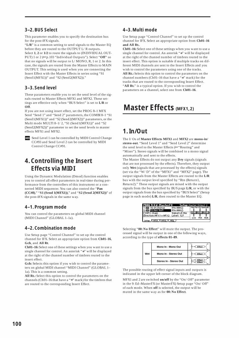
100
3–2. BUS SelectThis parameter enables you to specify the destination bus for the post-IFX signals.“L/R” is a common setting to send signals to the Master EQ before they are routed to the OUTPUT L/R outputs.Select 1, 2 or 1/2 to route the signals to (INDIVIDUAL OUT-PUT) 1 or 2 (☞p.103 “Individual Outputs”). Select “Off” so that no signals will be output to L/MONO, R, 1 or 2. In this case, the signals are routed from the Master Effects to MAIN OUTPUT. This setting is used when you are connecting the Insert Effect with the Master Effects in series using “S1 (Send1(MFX1))” and “S2 (Send2(MFX2)).”
3–3. Send levelThese parameters enable you to set the send level of the sig-nals routed to Master Effects MFX1 and MFX2. These set-tings are effective only when “BUS Select” is set to L/R or Off.If you are not using insert effect, set the PROG 8–1 MFX Send “Send 1” and “Send 2” parameters, the COMBI 8–1 “S1 (Send1(MFX1))” and “S2 (Send2(MFX2))” parameters, or the Multi mode MULTI 8–1/2, “S1 (Send1(MFX1))” and “S2 (Send2(MFX2))” parameter to set the send levels to master effects MFX1 and MFX2.
Send Level 1 can be controlled by MIDI Control Change CC#93 and Send Level 2 can be controlled by MIDI Control Change CC#91.
4. Controlling the Insert Effects via MIDI
Using the Dynamic Modulation (Dmod) function enables you to control all effect parameters in real-time during per-formance from the controllers of this instrument or a con-nected MIDI sequencer. You can also control the “Pan (CC#8),” “S1 (Send 1(MFX1)),” and “S2 (Send 2(MFX2))” of the post-IFX signals in the same way.
4–1. Program modeYou can control the parameters on global MIDI channel (MIDI Channel” (GLOBAL 1–1a).
4–2. Combination modeUse Setup page “Control Channel” to set up the control channel for IFX. Select an appropriate option from Ch01–16, Gch, and All Rt.Ch01–16: Select one of these settings when you want to use a single channel for control. An asterisk “*” will be displayed at the right of the channel number of timbres routed to the insert effect.Gch: Selects this option if you wish to control the parame-ters on global MIDI channel “MIDI Channel” (GLOBAL 1–1a). This is a common setting.All Rt.: Select this option to control the parameters on the channels (Ch01–16 that have a “*” mark) for the timbres that are routed to the corresponding Insert Effect.
4–3. Multi modeUse Setup page “Control Channel” to set up the control channel for IFX. Select an appropriate option from Ch01–16 and All Rt..Ch01–16: Select one of these settings when you want to use a single channel for control. An asterisk “*” will be displayed at the right of the channel number of timbres routed to the insert effect. This option is suitable if multiple tracks on dif-ferent MIDI channels are sent to the Insert Effects and you wish to control the parameters using one of the tracks.All Rt.: Selects this option to control the parameters on the channel numbers (Ch01–16 that have a “*” mark) for the tracks that are routed to the corresponding Insert Effect.“All Rt.” is a typical option. If you wish to control the parameters on a channel, select one from Ch01–16.
Master Effects (MFX1, 2)
1. In/OutThe I/Os of Master Effects MFX1 and MFX2 are mono-in/stereo-out. “Send Level 1” and “Send Level 2” determine the send level to the Master Effects (☞“Routing” and “Mixer”). Stereo signals will be combined to a mono signal automatically and sent to the effects.The Master Effects do not output any Dry signals (signals that are not processed by the effects). Therefore, they output only Wet (signals that are processed by the effects) signals (set via the “W/D” of the “MFX1” and “MFX2” page). The output signals from the Master Effects are routed to the L/R bus with the output level specified by “Rtn (Return1, Return2).” These output signals are mixed with the output signals from the bus specified by BUS page L/R, or with the output signals from the bus specified by “BUS Select” (Setup page in each mode) L/R, then routed to the Master EQ.
Selecting “00: No Effect” will mute the output. The pro-cessed signal will be output in one of the following ways, according to the type of effects 01–89.
The possible routing of effect signal inputs and outputs is indicated in the upper left corner of the block diagram.
MFX1 and 2 are switched on/off by the “On/Off” parameter in the 9: Ed–MasterFX (or MasterFX) Setup page “On/Off” of each mode. When off is selected, the output will be muted in the same way as for 00: No Effect.
Stereo In - Stereo Out
Mono In - Mono Out
Mono In - Stereo Out
EffectEffect
Effect+
Effect+
Wet
+
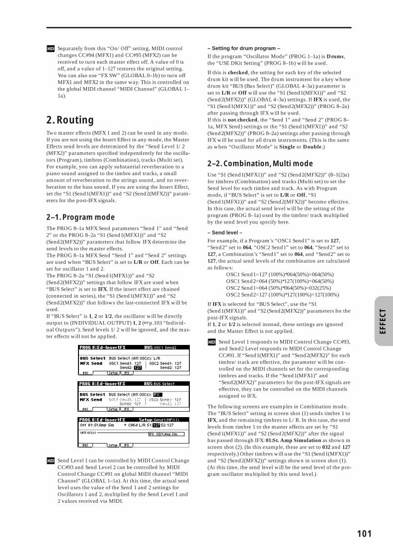
EFFE
CT
Separately from this “On/Off” setting, MIDI control changes CC#94 (MFX1) and CC#95 (MFX2) can be received to turn each master effect off. A value of 0 is off, and a value of 1–127 restores the original setting. You can also use “FX SW” (GLOBAL 0–1b) to turn off MFX1 and MFX2 in the same way. This is controlled on the global MIDI channel “MIDI Channel” (GLOBAL 1–1a).
2. RoutingTwo master effects (MFX 1 and 2) can be used in any mode. If you are not using the Insert Effect in any mode, the Master Effects send levels are determined by the “Send Level 1/2 (MFX2)” parameters specified independently for the oscilla-tors (Program), timbres (Combination), tracks (Multi set). For example, you can apply substantial reverberation to a piano sound assigned to the timbre and tracks, a small amount of reverberation to the strings sound, and no rever-beration to the bass sound. If you are using the Insert Effect, set the “S1 (Send1(MFX1))” and “S2 (Send2(MFX2))” param-eters for the post-IFX signals.
2–1. Program modeThe PROG 8–1a MFX Send parameters “Send 1” and “Send 2” or the PROG 8–2a “S1 (Send1(MFX1))” and “S2 (Send2(MFX2))” parameters that follow IFX determine the send levels to the master effects.The PROG 8–1a MFX Send “Send 1” and “Send 2” settings are used when “BUS Select” is set to L/R or Off. Each can be set for oscillator 1 and 2.The PROG 8–2a “S1 (Send1(MFX1))” and “S2 (Send2(MFX2))” settings that follow IFX are used when “BUS Select” is set to IFX. If the insert effect are chained (connected in series), the “S1 (Send1(MFX1))” and “S2 (Send2(MFX2))” that follows the last-connected IFX will be used.If “BUS Select” is 1, 2 or 1/2, the oscillator will be directly output to (INDIVIDUAL OUTPUT) 1, 2 (☞p.103 “Individ-ual Outputs”). Send levels 1/2 will be ignored, and the mas-ter effects will not be applied.
Send Level 1 can be controlled by MIDI Control Change CC#93 and Send Level 2 can be controlled by MIDI Control Change CC#91 on global MIDI channel “MIDI Channel” (GLOBAL 1–1a). At this time, the actual send level uses the value of the Send 1 and 2 settings for Oscillators 1 and 2, multiplied by the Send Level 1 and 2 values received via MIDI.
– Setting for drum program –
If the program “Oscillator Mode” (PROG 1–1a) is Drums, the “USE DKit Setting” (PROG 8–1b) will be used.
If this is checked, the setting for each key of the selected drum kit will be used. The drum instrument for a key whose drum kit “BUS (Bus Select)” (GLOBAL 4–3a) parameter is set to L/R or Off will use the “S1 (Send1(MFX1))” and “S2 (Send2(MFX2))” (GLOBAL 4–3a) settings. If IFX is used, the “S1 (Send1(MFX1))” and “S2 (Send2(MFX2))” (PROG 8–2a) after passing through IFX will be used.If this is not checked, the “Send 1” and “Send 2” (PROG 8–1a, MFX Send) settings or the “S1 (Send1(MFX1))” and “S2 (Send2(MFX2))” (PROG 8–2a) settings after passing through IFX will be used for all drum instruments. (This is the same as when “Oscillator Mode” is Single or Double.)
2–2. Combination, Multi modeUse “S1 (Send1(MFX1))” and “S2 (Send2(MFX2))” (8–1(2)a) for timbres (Combination) and tracks (Multi set) to set the Send level for each timbre and track. As with Program mode, if “BUS Select” is set to L/R or Off, “S1 (Send1(MFX1))” and “S2 (Send2(MFX2))” become effective. In this case, the actual send level will be the setting of the program (PROG 8–1a) used by the timbre/track multiplied by the send level you specify here.
– Send level –
For example, if a Program’s “OSC1 Send1” is set to 127, “Send2” set to 064, “OSC2 Send1” set to 064, “Send2” set to 127, a Combination’s “Send1” set to 064, and “Send2” set to 127, the actual send levels of the combination are calculated as follows:
OSC1 Send1=127 (100%)*064(50%)=064(50%)OSC1 Send2=064 (50%)*127(100%)=064(50%)OSC2 Send1=064 (50%)*064(50%)=032(25%)OSC2 Send2=127 (100%)*127(100%)=127(100%)
If IFX is selected for “BUS Select”, use the “S1 (Send1(MFX1))” and “S2 (Send2(MFX2))” parameters for the post-IFX signals.If 1, 2 or 1/2 is selected instead, these settings are ignored and the Master Effect is not applied.
Send Level 1 responds to MIDI Control Change CC#93, and Send2 Level responds to MIDI Control Change CC#91. If “Send1(MFX1)” and “Send2(MFX2)” for each timbre/track are effective, the parameter will be con-trolled on the MIDI channels set for the corresponding timbres and tracks. If the “Send1(MFX1)” and “Send2(MFX2)” parameters for the post-IFX signals are effective, they can be controlled on the MIDI channels assigned to IFX.
The following screens are examples in Combination mode. The “BUS Select” setting in screen shot (1) sends timbre 1 to IFX, and the remaining timbres to L/R. In this case, the send levels from timbre 1 to the master effects are set by “S1 (Send1(MFX1))” and “S2 (Send2(MFX2))” after the signal has passed through IFX: 01:St. Amp Simulation as shown in screen shot (2). (In this example, these are set to 032 and 127 respectively.) Other timbres will use the “S1 (Send1(MFX1))” and “S2 (Send2(MFX2))” settings shown in screen shot (1). (At this time, the send level will be the send level of the pro-gram oscillator multiplied by this send level.)
101

102
– Setting for drum program –
If a drum program has been selected for a timbre in Combi-nation mode or for a track in Multi mode, you will be able to select DKit for the “BUS Select” parameter. If this is selected, the “BUS (BUS Select)” (GLOBAL 4–3a) settings for each individual key will be used, and will be sent to the bus for each drum instrument. In this case, the send level will be determined by multiplying the value of the “S1 (Send1(MFX1))” and “S2 (Send2(MFX2))” settings of each key in the drum kit by the value of the “S1 (Send1(MFX1))” and “S2 (Send2(MFX2))” settings that you make here. (For the drum instruments of keys whose drum kit “BUS (BUS Select)” parameter is set to IFX, this is determined by “S1 (Send1(MFX1))” and “S2 (Send2(MFX2))” after the signal has passed through IFX.) If L/R or Off is selected, the send levels specified by PROG 8–1a “OSC1 Send 1” and “Send 2” will be multiplied by the “S1 (Send1(MFX1))” and “S2 (Send2(MFX2))” settings that you make here. (This is the same as when “Oscillator Mode” is Single or Double.) If IFX are selected, the “S1 (Send1(MFX1))” and “S2 (Send2(MFX2))” after the specified insert effect will be used. If 1, 2 or 1/2 are selected, “S1 (Send1(MFX1))” and “S2 (Send2(MFX2))” will be ignored.
3. MixerThe send levels determine the input levels of oscillators (Program), timbres (Combination), tracks (Multi set) that are routed to the Master Effects. The 9: Ed–MasterFX (or Mas-terFX) in all modes enable you to set the output levels and Master EQ gain values, and connect the Master Effects in series (chain).
3–1. Rtn (Return1, Return2)These specify the output levels from MFX1 and MFX2 respectively. The left value of the “W/D” specified for the effect selected in MFX 1 or 2 will be the output level of the master effect; e.g., 25% for 25:75, 100% for Wet, and 0% for Dry. This level multiplied by the “Rtn (Return 1, Return 2)” value will be sent to the L/R bus, and will be mixed with the 8–1a “BUS Select” L/R or 9–1a“BUS Select” L/R output sound.For example, with MFX1 “W/D” set to 50:50 (50%) and “Rtn (Return1)” set to 64 (50%), the resultant effect level will be 25%. The effect level is maximum (100%) when “W/D” is set to “Wet” and “Rtn (Return1)” is set to 127.
3–2. MFX ChainIf you check the “MFX Chain” check box, the signal will be routed between MFX1 and MFX2.The following figure indicates that the output from “MFX1:16: Stereo Chorus” is added to “MFX2: 52: Reverb Hall” input.
3–3. Chain DirectionSpecify the direction of the connection when the signal is routed between MFX1 and MFX2.
3–4. Chain SignalThis parameter enables you to select signals routed between MFX1 and 2. If the chain direction (order) is from MFX1 to MFX2, selecting LR Mix will cause the stereo L/R outputs from MFX1 to be mixed and input to MFX2. This setting is useful when you wish to serially connect delays that are panned to L and R (e.g., “43: LCR Delay”). Selecting L Only or R Only will cause only one channel of stereo outputs from MFX1 to be input to MFX2. This setting is suitable for a chain connection of a reverb effect and a modulation effect such as 16: St. Chorus.
3–5. Chain LevelThis parameter determines the level of signals routed from one MFX to the other MFX in a chain connection.
3–6. Master EQ Gain[dB]These parameters are used to set the gain of the Low, Mid, and High stereo three-band EQ that is located right before (MAIN OUTPUT) L/MONO and R. Low and High EQs are of the shelving type, and Mid EQ is a band type equalizer. These settings are linked with the Low, Mid, and High “Gain” parameters of the MEQ page. Use this MEQ page to set the center frequency, band width (for Mid), and dynamic modulation of the EQ bands.
4. Controlling the Master Effects via MIDI
You can use the Dynamic Modulation (Dmod) function to control all Master Effects parameters in real-time from this instrument’s controllers or from an external MIDI sequencer.
In Program mode, the parameters are controlled on global MIDI channel “MIDI Channel” (GLOBAL 1–1a).In Combination mode, and Multi mode, you can set the control channels for MFX1 and MFX2 using the Setup page “Control Channel” parameters of the “MFX1–2” tabs. Select the desired option from Ch01–16, and Gch.
Ch01–16: Select this option if you wish to control the param-eters for each Master Effect on different channels.Gch: Select this option if you wish to control the parameters on global MIDI channel “MIDI Channel” (GLOBAL 1–1a). This is the normal setting.
(1)
(2)

EFFE
CT
Master EQ
The Master EQ (stereo, three-band EQ) is located right before (MAIN OUTPUT) L/MONO, R. Low and High EQs are of the shelving type, and Mid EQ is a peaking type equalizer. You can control the Low Gain and High Gain parameters using the Dynamic Modulation function.The Master EQ (stereo, three-band EQ) is applied to the sig-nal input from the L/R bus. For more information on the parameters, p.149.
Individual Outputs
The X50/microX is equipped with two individual INDIVID-UAL OUTPUT. You can route the oscillator (Program), timbre (Combina-tion), and track (Multi) output or the post-IFX signals to these two individual outputs.Use “BUS Select” (8–1a) in Program, Combination, or Multi mode to route the oscillators (Program), timbres (Combina-tion), or tracks (Multi) to INDIVIDUAL OUTPUT.If you are using the Insert Effects, use “BUS Select” of the 8: Ed–InsertFX (or InsertFX), and Setup page to route the post-IFX signals.1, 2: Monaural signals are routed to INDIVIDUAL OUTPUT.1/2: Stereo signals are routed to INDIVIDUAL OUTPUT.
Program mode
Combination, Multi mode
Pan
Oscillator 1
Send1
Select from:L/R IFX121/2Off
IFX BUS IFX
MFX2
MFX1mono
mono
Return1 / 2
Master EQ (MAIN OUTPUT) L/MONO, R
BUS Select= L/R
Oscillator 2
IFX / Indiv.OutBUS Select
Insert EffectPost IFXPan(CC#8) BUS Select
Select from:L/R121/2Off
Send2
stereo
Master Effects
(INDIVIDUAL OUTPUT) 1/2
L/R BUS
mono x2mono x 2
BUS Select= IFX
stereo
stereo
Chain
Effect / Mixer Block Diagram in Program Mode
PROG 8: Insert Effect
Post IFXSend1 / 2
PROG 9: Master Effect
Pan
Timbre / Track 1 BUS Select= L/R
Send1
Select from:(DKIT)L/R IFX121/2Off
BUS Select= L/RIFX BUS IFX
MFX2
MFX1mono
mono
Return1 / 2
Master EQ (MAIN OUTPUT)L/MONO, R
Timbre / Track 2
Timbre / Track 3
BUS Select= OffTimbre / Track 4
BUS Select= 1/2Timbre / Track 8
BUS Select= 2Track 16
IFX / Indiv.OutBUS Select
Insert EffectPost IFXPan(CC#8) BUS Select
Select from:L/R121/2Off
Send2
stereo
Master Effects
(INDIVIDUAL OUTPUT) 1/2
L/R BUS
stereo
mono x 2mono x 2
BUS Select= 1
BUS Select= IFX
stereo
stereo
Chain
Effect / Mixer Block Diagram in Combination / Multi Mode
COMBI/MULTI 8: Insert Effect
Post IFXSend1 / 2
COMBI/MULTI 9: Master Effect
103

104
Filter/Dynamic
Filter and dynamics control effects
00: No EffectSelect this option when you do not wish to use any effects. The Insert Effect section outputs unprocessed signals and the Master Effect section mutes the output.
01: St.Amp Sim(Stereo Amp Simulation)
This effect simulates the frequency response characteristics of guitar amplifiers. It is also effective for organ and drum sounds.
02: St.Compressor
(Stereo Compressor)
This effect compresses the input signal to regulate the level and give a “punchy” effect. It is useful for guitar, piano, and drum sounds. This is a stereo compressor. You can link left and right channels, or use each channel separately.
a: EnvelopeThis parameter selects whether the left and right channels are linked to control both signals simultaneously, or whether each channel is controlled independently.
b: Sensitivity, d: LevelThe “Sensitivity” parameter sets the sensitivity of the compressor. If this parameter is set to a higher value, lower level sounds will be boosted. With a higher Sensitivity, the overall volume level is higher. To adjust the final volume level, use the “Level” parame-ter.
c: AttackThis parameter controls the attack level.
03: St.Limiter (Stereo Limiter)
The Limiter regulates the input signal level. It is similar to the Compressor, except that the Limiter compresses only signals that exceed the specified level to lower unnecessary peak sig-nals. The Limiter applies a peaking-type EQ to the trigger sig-nal (which controls the degree of the Limiter effect), allowing you to set any band width to be covered. This effect is a stereo limiter. You can link left and right channels, or use each chan-nel individually.
aAmplifier TypeSelect between three types of guitar amp simula-tors
SS, EL84, 6L6
b
W/D (Wet/Dry) Dry, 1:99...99:1, WetSets the balance between the effect and dry sounds
(Source) Off...TempoSelects the modulation source of the effect balance
(Amount)Sets the modulation amount of the effect balance
–100...+100
aEnvelope (Envelope Select) L/R Mix, L/R IndividuallyDetermines whether the left and right channels are linked or used separately ☞
b SensitivitySets the sensitivity
1...100☞
c AttackSets the attack level
1...100☞
Left
Right
Wet / Dry
Wet / Dry
Stereo In - Stereo Out
Amp Simulation Filter
Amp Simulation Filter
Left
Right
Wet / Dry
Wet / Dry
Stereo In - Stereo Out
EQ Trim
EQ Trim
LEQ HEQ
LEQ HEQCompressor
Compressor
Envelope Select
Output Level
Output Level
Envelope - Control
Envelope - Control
d
Level (Output Level)Sets the output level of the compressor
0...100☞,
(Source) Off...TempoSelects the modulation source for the compressor output level
(Amount) –100...+100Sets the modulation amount of the compressor output level
e Pre EQ TrimSets the EQ input level
0...100
f
LoEQ (Pre Low EQ Gain)Sets the gain of Low EQ
–15.0...+15.0dB
HiEQ (Pre High EQ Gain)Sets the gain of High EQ
–15.0...+15.0dB
g
W/D (Wet/Dly) Dry, 1:99...99:1, WetSets the balance between the effect and dry sounds
(Source) Off...TempoSelects the modulation source of the effect balance
(Amount)Sets the modulation amount of the effect balance
–100...+100
Sensitivity=100
Sensitivity=40Dry
Wet
Time
LevelCompressor - Sensitivity
Lo
ud
er
Dry
Wet
Time
Level
Attack=80
Attack=20
Compressor - Attack
Left
Right
Wet / Dry
Wet / Dry
Stereo In - Stereo Out
Limiter
Limiter
Envelope Select
Gain Adjust
Gain Adjust
Side PEQEnvelope - Control
Envelope - Control
Trigger Monitor+

EFFE
CT
a: EnvelopeWhen L/R Mix is selected for this parameter, the left and right channels are linked to control the Limiter using the mixed signal. If L Only (or R Only) is selected, the left and right channels are linked, and the Limiter is controlled via only the left (or right) channel.With L/R individually, the left and right channels control the Lim-iter individually.
b: Ratio, c: Threshold, i: G.AdjThis parameter sets the signal compression “Ratio”. Compression is applied only when the signal level exceeds the “Threshold” value.Adjust the output level using the “G.Adj” parameter, since com-pression causes the entire level to be reduced.
d: Attack, e: ReleaseThese parameters set the attack time and release time. A higher attack time will cause the compression to be applied more slowly.
f: Side PEQ Insert, h: EQ, h: Q, h: GThese parameters are used to set the EQ applied to the trigger sig-nal.The Limiter determines whether the compression is applied or not, based on the post-EQ trigger signal. Setting the equalizer allows you to set the Limiter to respond to any frequency band.
g: Trigger MonitorSetting this parameter On will cause the trigger signal to be out-put, instead of the effect sound. Use this parameter to check the trigger signal with EQ applied.Usually, set this to Off.
04: Mltband Limit (Multiband Limiter)
This effect applies the Limiter to the low range, mid range, and high range of the input signal. You can control dynamics for each range to adjust the sound pressure of the low range, mid range, and high range in a different way from the EQ.
a
Envelope (Envelope Select) L/R Mix, L Only, R Only, L/R IndividuallySelects from linking both channels, controlling only from left channel, only from the right channel, or controlling each channel individually
☞
b Ratio 1.0:1...50.0:1, Inf:1Sets the signal compression ratio ☞
c Threshold –40...0dBSets the level above which the compressor is applied ☞
d AttackSets the attack time
1...100☞
e ReleaseSets the release time
1...100☞
f Side PEQ InsertToggles between on/off of the trigger signal’s EQ
Off, On☞
gTrigger Monitor Off, OnSwitches between effect output monitor and trigger signal monitor
☞
h
EQ (Side PEQ Cutoff) 20...12.00kHzSets the EQ center frequency for the trigger signal ☞
QSets the EQ bandwidth for the trigger signal
0.5...10.0
G (Gain)Sets the EQ gain for the trigger signal
–18.0...+18.0dB
i
G.Adj (Gain Adjust)Sets the output gain
–Inf, –38...+24dB☞,
(Source)Selects the modulation source for the output gain
Off...Tempo
(Amount)Sets the modulation amount of the output gain
–63...+63
j
W/D (Wet/Dly) Dry, 1:99...99:1, WetSets the balance between the effect and dry sounds
(Source) Off...TempoSelects the modulation source of the effect balance
(Amount)Sets the modulation amount of the effect balance
–100...+100
Input Level
Output Level
Threshold
Ratio=1.0 : 1
Ratio=2.0 : 1
Ratio=4.0 : 1
Ration=Inf : 1
Louder
Lo
ud
er
Time
Level
Threshold
Ratio=Inf : 1
Ratio=2.0 : 1Ratio=4.0 : 1
Dry Ratio=1.0 : 1
Limiter - Threshold / Ratio
a Ratio 1.0:1...50.0:1, Inf:1Sets the signal compression ratio ☞ Fx:03
b Threshold –40...0dBSets the level above which the compressor is applied ☞ Fx:03
c AttackSets the attack time
1...100☞ Fx:03
d ReleaseSets the release time
1...100☞ Fx:03
e Low OffsetGain of the low-range trigger signal
–40...0dB☞
f Mid OffsetGain of the mid-range trigger signal
–40...0dB☞
g High OffsetGain of the high-range trigger signal
–40...0dB☞
h
G.Adj (Gain Adjust) –Inf, –38...+24dBSets the output gain ☞ Fx:03,
(Source)Selects the modulation source for the output gain
Off...Tempo
(Amount)Sets the modulation amount of the output gain
–63...+63
Threshold
Ratio=Inf : 1Attack=1Release=1
Ratio=Inf : 1Attack=100Release=100
Dry
Wet
Wet
Release
Attack
Limiter - Attack / Release
Left
Right
Wet / Dry
Wet / Dry
Wet: Mono In - Mono Out / Dry: Stereo In - Stereo Out
Gain AdjustMid Offset
Low Offset
High Offset
Limiter
Envelope - Control
Envelope - Control
Envelope - Control
Limiter
Limiter
Low
Mid
High
Band-Pass Filters
+
105

106
e: Low Offset, f: Mid Offset, g: High OffsetThese parameters set the gain of the trigger signal.For example, if you do not want to apply compression to the high range, reduce the “High Offset” value down below the “Thresh-old” level. In this way, the high range limiter will not respond, and compression will not be applied.
05: St.Gate (Stereo Gate)
This effect mutes the input signal if its level is lower than the specified level. It also reverses the on and off operation of the gate, and uses Note On and Off messages to turn the gate on and off.
a: Envelope, b: Env. Dmod SrcThe “Envelope” parameter selects whether the gate on/off is trig-gered by the level of the input signal, or controlled directly by the modulation source. The Src parameter specifies the modulation source, selected from Off to G2+Dmod.With “Envelope” = L/R Mix, the left and right channel signal mix-ture will trigger the gate on/off. When L Only or R Only is selected, the gate is controlled by either of the channel signals.
f: PolarityThis parameter reverses the Gate on/off operation. With a nega-tive value, the gate is closed when the input signal level exceeds the Threshold. The gate operation controlled by the modulation source is also reversed.
c: Threshold, d: Attack, e: ReleaseThis parameter sets the signal level below which Gate is applied when “Envelope” is set to L/R Mix, L Only, or R Only.The Attack and Release parameters set the Gate attack time and release time.
g: DelayThis parameter sets the delay time of the Gate input. If the sound has a very fast attack, increase the delay time so that the signal will be input after the Gate is opened. This will preserve the attack part of the sound.
06: OD/HiGain Wah (Overdrive/Hi.Gain Wah)
This distortion effect utilizes an Overdrive mode and a Hi-Gain mode. Controlling the wah effect, the 3-band EQ, and the amp simulation will allow you to create versatile distor-tion sounds. This effect is suitable for guitar and organ sounds.
i
W/D (Wet/Dly) Dry, 1:99...99:1, WetSets the balance between the effect and dry sounds
(Source) Off...TempoSelects the modulation source of the effect balance
(Amount)Sets the modulation amount of the effect balance
–100...+100
aEnvelope (Envelope Select) Dmod, L/R Mix, L Only, R OnlySelects from Control via the modulation source, mixing the left and right signals, Only left, and Only right ☞,
bEnv. Dmod Src (Envelope Dmod Source) Off...G2+DmpSelects the modulation source that controls the gate when Envelope = Dmod
c ThresholdSets the level to which the Gate is applied
0...100☞
d AttackSets the attack time
1...100☞
e ReleaseSets the release time
1...100☞
f Polarity +, –Switches between non-reversed and reversed Gate on/off ☞
g Delay (Delay Time)Sets the delay time of the gate input
0...100ms☞
h
W/D (Wet/Dly) Dry, 1:99...99:1, WetSets the balance between the effect and dry sounds
(Source) Off...TempoSelects the modulation source of the effect balance
(Amount)Sets the modulation amount of the effect balance
–100...+100
Left
Right
Wet / Dry
Wet / Dry
Stereo In - Stereo Out
+
Gate
Gate
Envelope Select
Envelope - Control
Envelope - Control
Delay
Delay
Gate+Dmpr
a
WahSwitches Wah on/off
Off, On☞,
(Source) Off...TempoSelects the modulation source that switches the Wah on and off
(Sw) Tggl, MmntSelects the switching mode for the modulation source that switches the Wah on and off ☞
b
Sweep Rng (Wah Sweep Range)Sets the range of Wah
–10...+10☞,
Src (Source) Off...TempoSelects the modulation source that controls the Wah ☞
c
Mode (Drive Mode) Overdrive, Hi-GainSwitches between overdrive and hi-gain distortion
DriveSets the degree of distortion
1...100☞
d Pre Low-cut 0...10Sets the low range cut amount of the distortion input ☞
Input Level
Output Level
Threshold
Louder
Lo
ud
er
Threshold
Attack=1Release=1
Attack=100Release=100
Dry
Wet
Wet
Attack Release
Gate - Attack / Release
Gate - Threshold
Left
Right
Wet / Dry
Wet / Dry
Wet: Mono In - Mono Out / Dry: Stereo In - Stereo Out
+ Amp Simulation3 Band PEQ
Output Level
Direct Mix
Pre Low-cut
D-mod
Wah
Mode: Overdrive / Hi-GainDrive
Driver

EFFE
CT
a: WahThe Wah parameter switches the wah effect on/off.
a: (Sw)This parameter sets how the wah effect is switched on and off via the modulation source.When “Sw” = Mmnt (Moment), the wah effect is usually turned off. It is turned on only when you press the pedal.
When a value for the modulation source is less than 64, “off” speed is selected, and when the value is 64 or higher, “on” is selected.
When “(Sw)” = Tggl (Toggle), the wah effect is switched between on and off each time you press the pedal.
The switch will be turned on/off each time the value of the modulation source exceeds 64.
b: SweepRng, b: SrcThis parameter sets the sweep range of the wah center frequency. A negative value will reverse the direction of sweep. The wah cen-ter frequency can be controlled by the modulation source speci-fied in the “Src” parameter.
d: Drive, e: LevelThe degree of distortion is determined by the level of input signal and the setting of “Drive”. Raising the “Drive” setting will cause the entire volume level to increase. Use the “Level” parameter to adjust the volume level. The “Level” parameter uses the signal level input to the 3-Band EQ. If clipping occurs at the 3-Band EQ, adjust the “Level” parameter.
d: Pre Low-cutCutting the signal in the low range before it is input to the Distor-tion will create a sharp distortion.
g: Q, h: QThese parameters set the bandwidth of each equalizer. The higher the value, the narrower the band becomes.
07: St.Para.4EQ (Stereo Parametric 4-Band EQ)
This is a stereo 4-band parametric equalizer. You can select peaking type or shelving type for Band 1 and 4. The gain of Band 2 can be controlled by dynamic modulation.
b: B1 Type, c: B4 TypeSelects a filter type for Band 1 and 4.
e
Level (Output Level)Sets the output level
0...50☞,
(Source)Selects the modulation source for the output level
Off...Tempo
(Amount)Sets the modulation amount of the output level
–50...+50
f
Lo (Low Cutoff ) 20...1.0kHzSets the center frequency for Low EQ (shelving type)
G (Gain)Sets the gain of Low EQ
–18...+18dB
g
M1 (Mid1 Cutoff) 300...10.00kHzSets the center frequency for Mid/High EQ 1 (peaking type)
QSets the band width of Mid/High EQ 1
0.5...10.0☞
G (Gain)Sets the gain of Mid/High EQ 1
–18...+18dB
h
M2 (Mid2 Cutoff) 500...20.00kHzSets the center frequency for Mid/High EQ 2 (peaking type)
QSets the band width of Mid/High EQ 2
0.5...10.0☞
G (Gain)Sets the gain of Mid/High EQ 2
–18...+18dB
i
Direct Mix 0...50Sets the amount of the dry sound mixed to the distortion
SpSim (Speaker Simulation)Switches the speaker simulation on/off
Off, On
j
W/D (Wet/Dly) Dry, 1:99...99:1, WetSets the balance between the effect and dry sounds
(Source) Off...TempoSelects the modulation source of the effect balance
(Amount)Sets the modulation amount of the effect balance
–100...+100
a TrimSets the input level
0...100
b B1 Type (Band1 Type) Peaking, Shelving-LowSelects the type of Band 1 ☞
c B4 Type (Band4 Type) Peaking, Shelving-HighSelects the type of Band 4 ☞
d
B2 Dyn.G Src (Band2 Dynamic Gain Source)Selects the modulation source of the Band 2 gain
Off...Tempo☞
(Amount)Sets the modulation amount of Band 2 gain
–18...+18dB☞
e
B1 (Band1 Cutoff)Sets the center frequency of Band 1
20...1.00kHz
QSets the bandwidth of Band 1
0.5...10.0☞ Fx:06
G (Gain)Sets the gain of Band 1
–18.0...+18.0dB
f
B2 (Band2 Cutoff)Sets the center frequency of Band 2
50...10.00kHz
QSets the bandwidth of Band 2
0.5...10.0☞ Fx:06
G (Gain)Sets the gain of Band 2
–18.0...+18.0dB☞,
g
B3 (Band3 Cutoff)Sets the center frequency of Band 3
300...10.00kHz
QSets the bandwidth of Band 3
0.5...10.0☞ Fx:06
G (Gain)Sets the gain of Band 3
–18.0...+18.0dB
h
B4 (Band4 Cutoff)Sets the center frequency of Band 4
500...20.00kHz
QSets the bandwidth of Band 4
0.5...10.0☞ Fx:06
G (Gain)Sets the gain of Band 4
–18.0...+18.0dB
i
W/D (Wet/Dly) Dry, 1:99...99:1, WetSets the balance between the effect and dry sounds
(Source) Off...TempoSelects the modulation source of the effect balance
(Amount)Sets the modulation amount of the effect balance
–100...+100
Left
Right
Wet / Dry
Wet / Dry
Stereo In - Stereo Out
Band1 Band2 Band3 Band4PEQ PEQ PEQ PEQ
LEQ
LEQ
HEQ
HEQ
PEQ PEQ PEQ PEQ
Trim
Trim
D-mod
3dB
3dB
Band1 Cutoff Band4 Cutoff
0dB
+Gain
–Gain Band1 Type=PeakingBand1 Type=Shelving Low
Band4 Type=PeakingBand4 Type=Shelving High
Parametric 4EQ - Band1, Band4 Type
107

108
d: B2 Dyn.G Src, d: (Amount), f: GYou can control the gain of Band 2 using the modulation source.
08: St.Graphic7EQ (Stereo Graphic 7-Band EQ)
This is a stereo 7-band graphic equalizer. The bar graph of the gain setting for each band gives you a clear, visual idea of fre-quency responses. You can select a center frequency setting for each band from twelve types, according to the sound.
a: TypeThis parameter selects a combination of center frequencies for each band. Select a combination of center frequencies for each band. The center frequency of each band is shown at the top of the LCD screen.
09: St.Wah/AutoW(Stereo Wah/Auto Wah)
This stereo wah effect allows you to create sounds from vin-tage wah pedal simulation to auto-wah simulation, and much broader range settings.
a
Type 1:Wide 1, 2:Wide 2, 3:Wide 3, 4:Half Wide 1, 5:Half Wide 2, 6:Half Wide 3, 7:Low, 8:Wide Low, 9:Mid, 10:Wide Mid, 11:High, 12:Wide HighSelects a combination of center frequencies for each band ☞
b TrimSets the input level
0...100
c (Band1)Sets the gain of Band 1
–18.0...+18.0dB
d (Band2)Sets the gain of Band 2
–18.0...+18.0dB
e (Band3)Sets the gain of Band 3
–18.0...+18.0dB
f (Band4)Sets the gain of Band 4
–18.0...+18.0dB
g (Band5)Sets the gain of Band 5
–18.0...+18.0dB
h (Band6)Sets the gain of Band 6
–18.0...+18.0dB
i (Band7)Sets the gain of Band 7
–18.0...+18.0dB
j
W/D (Wet/Dly) Dry, 1:99...99:1, WetSets the balance between the effect and dry sounds
(Source) Off...TempoSelects the modulation source of the effect balance
(Amount)Sets the modulation amount of the effect balance
–100...+100
Band2 Cutoff
Band2 Cutoff
0dB
+6dB
+15dB
Band2 Gain[dB]= +6.0Band2 Dynamic Gain Amt[dB]= +9.0
D-mod
0dB
+6dB
–9dB
Band2 Gain[dB]= +6.0Band2 Dynamic Gain Amt[dB]= –15.0
D-mod
Parametric 4EQ - Band2 Dynamic Gain Control
Left
Right
Wet / Dry
Wet / Dry
Stereo In - Stereo Out
Band1 Band2 Band3 Band4Trim
Trim
Band5 Band6 Band7
Band1 Band2 Band3 Band4 Band5 Band6 Band7
a
FreqBottm (Frequency Bottom)Sets the lower limit of the wah center frequency
0...100☞
FreqTop (Frequency Top)Sets the upper limit of the wah center frequency
0...100☞
b
Swp Mode (Sweep Mode) Auto, Dmod, LFOSelects the control from auto-wah, modulation source, and LFO
☞,
Src (Source) Off...TempoSelects the modulation source for the wah when Swp Mode=Dmod
c Response 0...100Sets the response speed when Swp Mode = Auto or Dmod
d Envelope Sens (Envelope Sensitivity)Sets the sensitivity of auto-wah
0...100☞
e Envelope ShapeSets the sweep curve of auto-wah
–100...+100☞
f
lfoF (LFO Frequency)Sets the LFO speed
0.02...20.00Hz☞,
(Source)Selects the modulation source of LFO speed
Off...Tempo
(Amount) –20.00...+20.00HzSets the modulation amount of LFO speed
g
BPM/MIDI Sync Off, OnSwitches between using the frequency of the LFO speed and using the tempo and notes ☞,
BPMSelects MIDI Clock and assigns tempo
MIDI, 40...240☞
Base (Base Note) � , � � , � , � � , � , � � , � , �Selects the type of notes that specify the LFO speed ☞
Times x1...x16Sets the number of notes that specify the LFO speed ☞
h
ResonanceSets the resonance amount
0...100
LPF (Low Pass Filter)Switches the Wah Low Pass Filter on and off
Off, On
i
W/D (Wet/Dly) Dry, 1:99...99:1, WetSets the balance between the effect and dry sounds
(Source) Off...TempoSelects the modulation source of the effect balance
(Amount)Sets the modulation amount of the effect balance
–100...+100
Stereo In - Stereo Out
D-mod
Envelope Sens
Envelope ShapeResponse
Wet / Dry
WahSweep Mode
D-modAuto
Left
RightWet / Dry
LFO
LFOWah
+

EFFE
CT
a: FreqBottm, a: FreqTopThe sweep width and direction of the wah filter are determined by the “FreqBottm” and “FreqTop” settings.
b: Swp ModeThis parameter changes the wah control mode. Setting “Swp Mode” to Auto will select an auto-wah that sweeps according to envelope changes in the input signal level. Auto-wah is frequently used for funk guitar parts and clav sounds.When “Swp Mode” is set to Dmod, you can control the filter directly via the modulation source in the same way as a wah pedal.When “Swp Mode” is set to LFO, the effect uses LFO to sweep in cycle.
d: Envelope SensThis parameter sets the sensitivity of auto-wah. Increase the value if the input signal is too low to sweep. Reduce the value if the input signal is so high that the filter is stopped temporarily.
e: Envelope ShapeThis parameter determines the sweep curve for auto-wah.
f: lfoF, g: BPM/MIDI SyncWhen “BPM/MIDI Sync”=Off, the LFO speed uses the lfoF parameter setting. When “BPM/MIDI Sync”=On, the LFO speed follows the “BPM”, “Base”, and “Times” settings.
g: BPM, g: Base, g: TimesOne cycle of LFO sweep is obtained by multiplying the length of a note (�…�) (selected for “Base”, in relation to the tempo specified in (“BPM”, or the MIDI Clock tempo if “BPM” is set to MIDI) by the number specified in the Times parameter.
10: St.Rndm Filter(Stereo Random Filter)
This stereo band pass filter uses a step-shape waveform and random LFO for modulation. You can create a special effect from filter oscillation.
a: LFO Wave, c: Freq, d: StepWhen “LFO Wave” is set to Step-Tri, LFO is a step-shape, triangle waveform. The “Freq” parameter sets the original triangle wave-form speed. Changing the “Step” parameter enables you to adjust the width of the steps.
Frequency
Bottom=25
Top=75
Hig
her
MaxZeroHigher D-mod
Frequency
Bottom=60
Top=30
Hig
her
MaxZeroHigher D-mod
Sweep Mode=D-mod
Frequency
Bottom=25
Top=75
Hig
her
Frequency
Bottom=75
Top=25
Hig
her
Sweep Mode=Auto
Envelope EnvelopeTime
Wah
Woo Woo
Woo
Envelope
Wah Wah
Time
Woo
Woo
Wah
Wah
Time
Level
Envelope
value = 0...–100
value = 0...+100
Envelope Shape
a LFO Wave (LFO Waveform)Selects LFO Waveform
Step-Tri, Random☞
b LFO Phase –180...+180degSets the LFO phase difference between the left and right ☞
c
Freq (LFO Frequency)Sets the LFO speed
0.02...20.00Hz☞,
(Source) Off...TempoSelects the modulation source used for both LFO speed and step speed
(Amount) –20.00...+20.00HzSets the modulation amount of LFO speed
d
Step (LFO Step Frequency) 0.05...50.00HzSets the LFO step speed (speed that changes in steps) ☞,
(Amount) –50.00...+50.00HzSets the modulation amount of LFO step speed
e
ManualSets the filter center frequency
0...100
ResonanceSets the resonance amount
0...100
f
BPM/MIDI Sync Off, OnSwitches between using the frequency of the LFO speed and using the tempo and notes ☞ Fx:09,
BPMSelects MIDI Clock and assigns tempo
MIDI, 40...240☞ Fx:09, ☞
Base (Base Note) � � � � � � � � � � � � � � � � � �Selects the type of notes that specify the LFO speed ☞ Fx:09
Times x1...x16Sets the number of notes that specify the LFO speed ☞ Fx:09
g
StepBase (Step Base Note) � � � � � � � � � � � � � � � � � � � � � � �Selects the type of notes to specify the LFO step speed ☞,
Times x1...x32Sets the number of notes to specify the LFO step speed ☞
h
Depth 0...100Sets the modulation depth of filter center frequency
(Source)Selects the modulation source of filter modula-tion
Off...Tempo
(Amount)Sets the modulation amount of filter modulation
–100...+100
i
W/D (Wet/Dly) –Wet...–1:99, Dry, 1:99...WetSets the balance between the effect and dry sounds ☞,
(Source) Off...TempoSelects the modulation source of the effect balance
(Amount)Sets the modulation amount of the effect balance
–100...+100
Filter
Left
Right
Wet / Dry
Wet / Dry
Stereo In - Stereo Out
Filter
LFO Phase
LFO: Step-Tri/Random
109

110
When “LFO Wave” is set to Random, the “Step” parameter uses a random LFO cycle.
b: LFO PhaseOffsetting the left and right phases alters how modulation is applied to the left and right channels, creating a swelling affect.
f: BPM, g: StepBase, g: TimesThe width of an LFO step, or a cycle of random LFO, is obtained by multiplying the length of a note (�…�) (selected for “Step-Base”, in relation to the tempo specified in “BPM,” or the MIDI Clock tempo if “BPM” is set to MIDI) by the number specified in the “Times” parameter.
j: W/DThe effect sound’s phase will be reversed when you set this parameter in the range of values from –Wet to –1:99.
11: St.Exct/Enhcr(Stereo Exciter/Enhancer)
This effect is a combination of the Exciter, which adds a punch to the sound and the Enhancer, which adds spread and pres-ence.
a: BlendThis parameter sets the depth (intensity) of the Exciter effect. Pos-itive values give a frequency pattern (to be emphasized) different from negative values.
b: PointThis parameter sets the frequency to be emphasized. Higher val-ues will emphasize lower frequencies.
c: Enh Dly L, d: Enh Dly RThese parameters set the delay time for the Enhancer left and right channel. Specifying a slightly different delay time for the left and right channel will add a stereo image, depth, and width to the sound.
12: St.Sub OSC(Stereo Sub Oscillator)
This effect adds very low frequencies to the input signal. It is very useful when simulating a roaring drum sound or emphasizing powerful low range. This effect is different from the equalizer in that you can add very low range harmonics. You can also adjust the oscillator frequency to match a partic-ular note number, for use as an octaver.
a
Blend (Exciter Blend)Sets the intensity (depth) of the Exciter effect
–100...+100☞,
(Source) Off...TempoSelects the modulation source of the Exciter intensity
(Amount) –100...+100Sets the modulation amount of the Exciter intensity
b
Point (Emphatic Point)Sets the frequency to be emphasized
0...70☞,
(Source) Off...TempoSelects the modulation source of the frequency to be emphasized
(Amount) –70...+70Sets the amount of modulation of the frequency to be emphasized
c Enh Dly L (Enhancer Delay L)Sets the delay time for the Enhancer left channel
0.0...50.0ms☞
d Enh Dly R (Enhancer Delay R) [msec] 0.0...50.0msSets the delay time for the Enhancer right channel ☞
Random Filter LFO
LFO Step Freq
LFO Frequency
LFO Step Freq
Step-Tri Random
LFO Phase
0 +90 +180 [degree]
0 [degree]–90–180
Left
Right
Wet / Dry
Wet / Dry
Stereo In - Stereo Out
EQ Trim
LEQ HEQ
EQ Trim
Delay
Delay
Depth
D-mod
Exciter
ExciterEnhancer
e
Enh Dep (Enhancer Depth) 0...100Sets the determines to what degree the Enhancer effect is applied
(Source) Off...TempoSelects the modulation source of the Enhancer width
(Amount) –100...+100Sets the modulation amount of the Enhancer width
f Pre EQ TrimSets the EQ input level
0...100
g
LoEQ (Pre Low EQ Gain)Sets the gain of Low EQ
–15.0...+15.0dB
HiEQ (Pre High EQ Gain)Sets the gain of High EQ
–15.0...+15.0dB
h
W/D (Wet/Dly) Dry, 1:99...99:1, WetSets the balance between the effect and dry sounds
(Source) Off...TempoSelects the modulation source of the effect balance
(Amount)Sets the modulation amount of the effect balance
–100...+100
aOSC Mode Note (Key Follow), FixedDetermines whether the oscillator frequency follows the note number or whether it is fixed ☞
bNote Interval –48...0Sets the pitch difference from the note number when OSC Mode=Note (Key Follow) ☞
c Fine (Note Fine)Fine adjustment of the oscillator frequency
–100...+100☞
d
Fixed (Fixed Frequency) 10.0...80.0HzSets the oscillator frequency when OSC Mode=Fixed
(Source) Off...TempoSelects the modulation source for the oscillator frequency when OSC Mode=Fixed
(Amount) –80...+80HzSets the oscillator frequency modulation amount when OSC Mode=Fixed
Wet / Dry
Note No.
OSC Mode
Fixed
Note (Key Follow)
Sine OscillatorFixed Frequency
Pitch
Note Interval, Fine
Stereo In - Stereo Out
Left
RightWet / Dry
Envelope Sens
Envelope Shape
Envelope Shape
D-mod
Pre LPF
Envelope Sens Pre LPF

EFFE
CT
a: OSC Mode, b: Note Interval, c: FineThe “OSC Mode” parameter selects the oscillator operation mode. When Note (Key Follow) is selected, the oscillator’s frequency is determined based on the note number, allowing you to use it as an octaver. The “Note Interval” parameter sets the pitch offset from the original note number by semitone steps. The “Fine” parameter allows you to fine-tune in steps of cents.
e: Envelope Pre LPFThis parameter sets the upper limit of the frequency range to which very low harmonics are added. Adjust this parameter if you do not want to add lower harmonics to the higher range.
13: Talking Mod (Talking Modulator)
This effect adds an unusual character, like a human voice, to the input signal. Modulating the tone via dynamic modula-tion, you can create an interesting effect that sounds as if the guitar or synthesizer is talking.
d: Top, d: Center, d: BottomThese parameters assign vowels to the top, center, and bottom position of the controller.Example: Suppose that “Top” is set to A, “Center” to I, and “Bot-tom” to U.If “Sweep Mode” is set to Dmod and “Control Src” to PBEND (microX: JSX), moving the [PITCH] wheel from the lowest (down) position to the highest (up) position (microX: moving the joystick from the right edge toward the left edge) will change the vocal character through the range “aah,” “iih” and “uuh.”If Sweep Mode is set to LFO, the sound will change cyclically from “a” to “i,” “u,” “i,” then “a.”
e: Formant ShiftThis parameter adjusts the frequency level to which the effect is applied. If you wish to apply the effect to a higher-range sound, set this parameter to a higher value; to apply the effect to a lower-range sound, set this to a lower value.
h: ResonanceThis parameter sets the intensity of resonance for the voice pat-tern. A larger value will add more character to the sound.
eEnvelope Pre LPF 1...100Sets the upper limit of the frequency range for which very low har-monics are added ☞
f Envelope Sens (Envelope Sensitivity) 0...100Sets the sensitivity with which very low harmonics are added
g Envelope ShapeSets the oscillator’s volume envelope curve
–100...+100
h
W/D (Wet/Dly) Dry, 1:99...99:1, WetSets the balance between the effect and dry sounds
(Source) Off...TempoSelects the modulation source of the effect balance
(Amount)Sets the modulation amount of the effect balance
–100...+100
aSweep Mode Dmod, LFOSwitches between modulation source control and LFO control
b Voice Control Bottom, 1...49, Center, 51...99, TopVoice pattern control
c Control Src (Control Source) Off...TempoSelects the modulation source that controls the voice pattern
d
Top (Voice Top)Selects a vowel sound at the top end of control
A, I, U, E, O☞
Center (Voice Center)Selects a vowel sound in the center of control
A, I, U, E, O☞
Bottom (Voice Bottom) A, I, U, E, OSelects a vowel sound at the bottom end of control ☞
e Formant Shift –100...+100Sets the frequency to which the effect is applied ☞
f
lfoF (LFO Frequency) 0.02...20.00HzSets the LFO speed ☞ Fx:09,
(Source)Selects the modulation source of LFO speed
Off...Tempo
(Amount) –20.00...+20.00HzSets the modulation amount of LFO speed
Wet: Mono In - Mono Out / Dry: Stereo In - Stereo Out
Left
Right
Wet / Dry
Wet / Dry
+
D-modVoice Top: A
Voice Center: IVoice Bottom: U
A - I - U - E - OTalking Modulator
LFO
D-modLFO
Sweep Mode
g
BPM/MIDI Sync Off, OnSwitches between using the frequency of the LFO speed and using the tempo and notes ☞ Fx:09,
BPMSelects MIDI Clock and assigns tempo
MIDI, 40...240☞ Fx:09
Base (Base Note) � � � � � � � � � � � � � � � � � �Selects the type of notes that specify the LFO speed ☞ Fx:09
Times 1...16Sets the number of notes that specify the LFO speed ☞ Fx:09
h ResonanceSets the Level of resonance of the voice pattern
0...100☞
i
W/D (Wet/Dly) Dry, 1:99...99:1, WetSets the balance between the effect and dry sounds
(Source) Off...TempoSelects the modulation source of the effect balance
(Amount)Sets the modulation amount of the effect balance
–100...+100
+ MaxZeroD-mod
– Max
Voice Bottom Voice Center Voice Top
U
I
AA
O
E
PBENDJS XRbn#16
M.Whl#1JS+Y#1JS–Y#2etc…
Zero+ Max
Talking Modulator Control
111
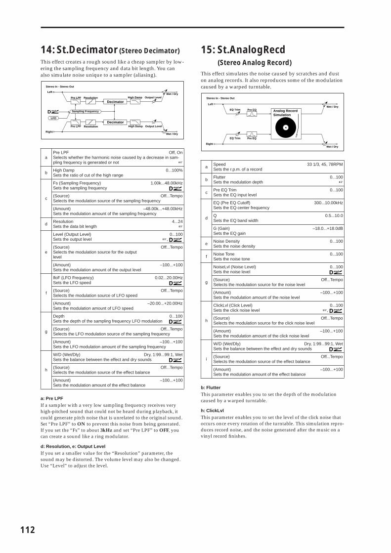
112
14: St.Decimator (Stereo Decimator)
This effect creates a rough sound like a cheap sampler by low-ering the sampling frequency and data bit length. You can also simulate noise unique to a sampler (aliasing).
a: Pre LPFIf a sampler with a very low sampling frequency receives very high-pitched sound that could not be heard during playback, it could generate pitch noise that is unrelated to the original sound. Set “Pre LPF” to ON to prevent this noise from being generated.If you set the “Fs” to about 3kHz and set “Pre LPF” to OFF, you can create a sound like a ring modulator.
d: Resolution, e: Output LevelIf you set a smaller value for the “Resolution” parameter, the sound may be distorted. The volume level may also be changed. Use “Level” to adjust the level.
15: St.AnalogRecd(Stereo Analog Record)
This effect simulates the noise caused by scratches and dust on analog records. It also reproduces some of the modulation caused by a warped turntable.
b: FlutterThis parameter enables you to set the depth of the modulation caused by a warped turntable.
h: ClickLvlThis parameter enables you to set the level of the click noise that occurs once every rotation of the turntable. This simulation repro-duces record noise, and the noise generated after the music on a vinyl record finishes.
aPre LPF Off, OnSelects whether the harmonic noise caused by a decrease in sam-pling frequency is generated or not ☞
b High DampSets the ratio of cut of the high range
0...100%
c
Fs (Sampling Frequency)Sets the sampling frequency
1.00k...48.00kHz
(Source) Off...TempoSelects the modulation source of the sampling frequency
(Amount) –48.00k...+48.00kHzSets the modulation amount of the sampling frequency
d ResolutionSets the data bit length
4...24☞
e
Level (Output Level)Sets the output level
0...100☞,
(Source)Selects the modulation source for the output level
Off...Tempo
(Amount)Sets the modulation amount of the output level
–100...+100
f
lfoF (LFO Frequency)Sets the LFO speed
0.02...20.00Hz
(Source)Selects the modulation source of LFO speed
Off...Tempo
(Amount) –20.00...+20.00HzSets the modulation amount of LFO speed
g
Depth 0...100Sets the depth of the sampling frequency LFO modulation
(Source) Off...TempoSelects the LFO modulation source of the sampling frequency
(Amount) –100...+100Sets the LFO modulation amount of the sampling frequency
h
W/D (Wet/Dly) Dry, 1:99...99:1, WetSets the balance between the effect and dry sounds
(Source) Off...TempoSelects the modulation source of the effect balance
(Amount)Sets the modulation amount of the effect balance
–100...+100
Left
Right
Wet / Dry
Wet / Dry
Stereo In - Stereo Out
Pre LPF
Pre LPF
High Damp Output Level
High Damp Output Level
Sampling Frequency
Decimator
Decimator
D-mod
LFO
Resolution
Resolution
a Speed 33 1/3, 45, 78RPMSets the r.p.m. of a record
b FlutterSets the modulation depth
0...100☞
c Pre EQ TrimSets the EQ input level
0...100
d
EQ (Pre EQ Cutoff)Sets the EQ center frequency
300...10.00kHz
QSets the EQ band width
0.5...10.0
G (Gain)Sets the EQ gain
–18.0...+18.0dB
e Noise DensitySets the noise density
0...100
f Noise ToneSets the noise tone
0...100
g
NoiseLvl (Noise Level)Sets the noise level
0...100
(Source)Selects the modulation source for the noise level
Off...Tempo
(Amount)Sets the modulation amount of the noise level
–100...+100
h
ClickLvl (Click Level)Sets the click noise level
0...100☞,
(Source) Off...TempoSelects the modulation source for the click noise level
(Amount) –100...+100Sets the modulation amount of the click noise level
i
W/D (Wet/Dly) Dry, 1:99...99:1, WetSets the balance between the effect and dry sounds
(Source) Off...TempoSelects the modulation source of the effect balance
(Amount)Sets the modulation amount of the effect balance
–100...+100
Left
Right
Wet / Dry
Wet / Dry
Stereo In - Stereo Out
Analog RecordSimulation
Pre EQ
Pre EQ
EQ Trim
EQ Trim

EFFE
CT
Pitch/Phase Mod.
Pitch/phase modulation effects
16: St.Chorus (Stereo Chorus)
This effect adds thickness and warmth to the sound by modu-lating the delay time of the input signal. You can add spread to the sound by offsetting the phase of the left and right LFOs from each other.
e: L Dly, e: R DlySetting the left and right delay time individually allows you to control the stereo image.
17: St.HarmnicCho (Stereo Harmonic Chorus)
This effect applies chorus only to higher frequencies. This can be used to apply a chorus effect to a bass sound without mak-ing the sound thinner. You can also use this chorus block with feedback as a flanger.
e: Hi/Lo SplitThis parameter sets the frequency that splits the high and low range. Only the high range will be sent to the chorus block.
a LFO Wave (LFO Waveform)Selects LFO Waveform
Triangle, Sine
b LFO Phase –180...+180degSets the LFO phase difference between the left and right ☞ Fx:10
c
Freq (LFO Frequency) 0.02...20.00HzSets the LFO speed ☞ Fx:09,
(Source)Selects the modulation source of LFO speed
Off...Tempo
(Amount) –20.00...+20.00HzSets the modulation amount of LFO speed
d
BPM/MIDI Sync Off, OnSwitches between using the frequency of the LFO speed and using the tempo and notes ☞ Fx:09,
BPMSelects MIDI Clock and assigns tempo
MIDI, 40...240☞ Fx:09
Base (Base Note) � � � � � � � � � � � � � � � � � �Selects the type of notes that specify the LFO speed ☞ Fx:09
Times 1...16Sets the number of notes that specify the LFO speed ☞ Fx:09
e
L Dly (L Pre Delay)Sets the delay time for the left channel
0.0...50.0ms☞
R Dly (R Pre Delay)Sets the delay time for the right channel
0.0...50.0ms☞
f
DepthSets the depth of LFO modulation
0...100
(Source) Off...TempoSelects the modulation source of the LFO modulation depth
(Amount) –100...+100Sets the modulation amount of the LFO modulation depth
g Pre EQ TrimSets the EQ input level
0...100
h
LoEQ (Pre Low EQ Gain)Sets the gain of Low EQ
–15.0...+15.0dB
HiEQ (Pre High EQ Gain)Sets the gain of High EQ
–15.0...+15.0dB
i
W/D (Wet/Dly) –Wet...–1:99, Dry, 1:99...WetSets the balance between the effect and dry sounds
☞ Fx:10,
(Source) Off...TempoSelects the modulation source of the effect balance
(Amount)Sets the modulation amount of the effect balance
–100...+100
Chorus
Chorus
Left
Right
LFO Phase
Wet / Dry
Wet / Dry
Stereo In - Stereo Out
EQ Trim
EQ Trim
LEQ HEQ
LEQ HEQ
LFO: Tri / Sine
a LFO Wave (LFO Waveform)Selects LFO Waveform
Triangle, Sine
b LFO Phase –180...+180degSets the LFO phase difference between the left and right ☞ Fx:10
c
Freq (LFO Frequency) 0.02...20.00HzSets the LFO speed ☞ Fx:09,
(Source)Selects the modulation source of LFO speed
Off...Tempo
(Amount) –20.00...+20.00HzSets the modulation amount of LFO speed
d
BPM/MIDI Sync Off, OnSwitches between using the frequency of the LFO speed and using the tempo and notes ☞ Fx:09,
BPMSelects MIDI Clock and assigns tempo
MIDI, 40...240☞ Fx:09
Base (Base Note) � � � � � � � � � � � � � � � � � �Selects the type of notes that specify the LFO speed ☞ Fx:09
Times 1...16Sets the number of notes that specify the LFO speed ☞ Fx:09
e
Dly (Delay Time)Sets the delay time from the original sound
0.0...50.0ms
Hi/Lo Split (High/Low Split Point) 1...100Sets the frequency split point between the high and low range ☞
f
DepthSets the depth of LFO modulation
0...100
(Source) Off...TempoSelects the modulation source of the LFO modulation depth
(Amount) –100...+100Sets the modulation amount of the LFO modulation depth
g
FeedbackSets the feed back amount of the chorus block
–100...+100☞
HiDamp (High Damp) 0...100%Sets the high range damping amount of the chorus block
h
Lo Level (Low Level)Sets the low range output level
0...100
Hi Level (High Level)Sets the high range (chorus) output level
0...100
i
W/D (Wet/Dly) Dry, 1:99...99:1, WetSets the balance between the effect and dry sounds
(Source) Off...TempoSelects the modulation source of the effect balance
(Amount)Sets the modulation amount of the effect balance
–100...+100
Left
Right
Feedback
LFO Phase
LFO: Tri / Sine
Wet / Dry
Wet / Dry
High Damp
Stereo In - Stereo Out
Low Level
Low Level
High Level
High Level
High/Low Split PointHigh Damp
Chorus/Flanger
Chorus/Flanger
113

114
g: FeedbackSets the feedback amount of the chorus block. Increasing the feed-back will allow you to use the effect as a flanger.
18: MltTap ChoDly (Multitap Chorus/Delay)
This effect has four chorus blocks with a different LFO phase. You can create a complex stereo image by setting each block’s delay time, depth, output level, and pan individually. You can also fix some of the chorus blocks to combine the chorus and delay effects.
19: EnsembleThis Ensemble effect has three chorus blocks that use LFO to create subtle shimmering, and gives three dimensional depth and spread to the sound, because the signal is output from the left, right, and center.
c: ShimmerThis parameter sets the amount of shimmering of the LFO wave-form. Increasing this value adds more shimmering, making the chorus effect more complex and richer.
a LFO Freq (LFO Frequency)Sets the LFO speed
0.02...13.00Hz
b
T1(000) (Tap1 Delay)Sets the Tap1 (LFO phase=0 degrees) delay time
0...570ms
D (Depth)Sets the Tap1 chorus depth
0...30
L (Level)Sets the Tap1 output level
0...30
P (Pan) L6...L1, C, R1...R6Sets the Tap1 stereo image
c
T2(180) (Tap2 Delay) 0...570msSets the Tap2 (LFO phase=180 degrees) delay time
D (Depth)Sets the Tap2 chorus depth
0...30
L (Level)Sets the Tap2 output level
0...30
P (Pan) L6...L1, C, R1...R6Sets the Tap2 stereo image
d
T3(090) (Tap3 Delay) 0…570msSets the Tap3 (LFO phase=90 degrees) delay time
D (Depth)Sets the Tap3 chorus depth
0...30
L (Level)Sets the Tap3 output level
0...30
P (Pan) L6...L1, C, R1...R6Sets the Tap3 stereo image
e
T4(270) (Tap4 Delay) 0...570msSets the Tap4 (LFO phase=270 degrees) delay time
D (Depth)Sets the Tap4 chorus depth
0...30
L (Level)Sets the Tap4 output level
0...30
P (Pan) L6...L1, C, R1...R6Sets the Tap4 stereo image
f
T1 Fb (Tap1 Feedback)Sets the Tap1 feedback amount
–100...+100
(Source) Off...TempoSelects the modulation source of Tap1 feedback amount and effect balance
(Amount) –100...+100Sets the Tap1 feedback amount and modulation amount
g
W/D (Wet/Dly) Dry, 1:99...99:1, WetSets the balance between the effect and dry sounds
(Amount)Sets the modulation amount of the effect balance
–100...+100
Left
Right
Feedback Wet / Dry
Wet / Dry
Wet: Mono In - Stereo Out / Dry: Stereo In -Stereo Out
+ Level
Level
Level
Level
Pan
Pan
Pan
Pan
LFO: Triangle
Tap1 Delay
Tap2 Delay
Tap3 Delay
Tap4 Delay
0 [degree]180 [degree]90 [degree]
270 [degree]
a
SpeedSets the LFO speed
1...100
(Source)Selects the modulation source of LFO speed
Off...Tempo
(Amount)Sets the modulation amount of LFO speed
–100...+100
b
DepthSets the depth of LFO modulation
0...100
(Source) Off...TempoSelects the modulation source of the LFO modulation depth
(Amount) –100...+100Sets the modulation amount of the LFO modulation depth
c Shimmer 0...100Sets the amount of shimmering of the LFO waveform ☞
d
W/D (Wet/Dly) Dry, 1:99...99:1, WetSets the balance between the effect and dry sounds
(Source) Off...TempoSelects the modulation source of the effect balance
(Amount)Sets the modulation amount of the effect balance
–100...+100
Left
Right
Wet / Dry
Wet / Dry
Wet: Mono In - Stereo Out / Dry: Stereo In - Stereo Out
LFO
Shimmer
+ Ensemble
Time
LevelEnsemble LFO
Shimmer

EFFE
CT
20: St.Flanger (Stereo Flanger)
This effect gives a significant swell and movement of pitch to the sound. It is more effective when applied to a sound with a lot of harmonics. This is a stereo flanger. You can add spread to the sound by offsetting the phase of the left and right LFOs from each other.
a: ShapeChanging the LFO waveform shape controls the peak sweep of flanging effects.
g: Feedback, i: W/DThe peak shape of the positive and negative “Feedback” value is different. The harmonics will be emphasized when the effect sound is mixed with the dry sound if you set a positive value for both “Feedback” and “W/D”, and if you set a negative value for both “Feedback” and “W/D”.
h: High DampThis parameter sets the amount of damping of the feedback in the high range. Increasing the value will cut high-range harmonics.
21: St.Rndm Flang (Stereo Random Flanger)
The stereo effect uses a step-shape waveform and random LFO for modulation, creating a unique flanging effect.
a
LFO Wave (LFO Waveform)Selects LFO Waveform
Tri, Sine
Shape (LFO Shape) –100...+100Determines how much the LFO waveform is changed ☞
b LFO Phase –180...+180degSets the LFO phase difference between the left and right ☞ Fx:10
c
Freq (LFO Frequency) 0.02...20.00HzSets the LFO speed ☞ Fx:09,
(Source)Selects the modulation source of LFO speed
Off...Tempo
(Amount) –20.00...+20.00HzSets the modulation amount of LFO speed
d
BPM/MIDI Sync Off, OnSwitches between using the frequency of the LFO speed and using the tempo and notes ☞ Fx:09,
BPMSelects MIDI Clock and assigns tempo
MIDI, 40...240☞ Fx:09
Base (Base Note) � � � � � � � � � � � � � � � � � �Selects the type of notes that specify the LFO speed ☞ Fx:09
Times 1...16Sets the number of notes that specify the LFO speed ☞ Fx:09
e Delay (Delay Time)Sets the delay time from the original sound
0.0...50.0ms
f DepthSets the depth of LFO modulation
0...100
g FeedbackSets the feedback amount
–100...+100☞
h High Damp 0...100%Sets the feedback damping amount in the high range ☞
i
W/D (Wet/Dly) –Wet...–1:99, Dry, 1:99...WetSets the balance between the effect and dry sounds
☞ Fx:10,
(Source) Off...TempoSelects the modulation source of the effect balance
(Amount)Sets the modulation amount of the effect balance
–100...+100
Flanger
Flanger
Left
Right
Feedback
LFO Shape
LFO Phase
LFO: Tri / Sine
Wet / Dry
Wet / Dry
High Damp
Stereo In - Stereo Out
LFO Shape
LFO Shape = 0...+100 LFO Shape = 0...–100
LFO Waveform=Sine
a LFO Wave (LFO Waveform)Selects LFO Waveform
Step-Tri, Random☞ Fx:10
b LFO Phase –180...+180degSets the LFO phase difference between the left and right ☞ Fx:10
c
Freq (LFO Frequency) 0.02...20.00HzSets the LFO speed ☞ Fx:10,
(Source) Off...TempoSelects the modulation source used for both LFO speed and step speed
(Amount) –20.00...+20.00HzSets the modulation amount of LFO speed
d
Step (LFO Step Frequency) 0.05...50.00HzSets the LFO step speed (speed that changes in steps)
☞ Fx:10,
(Amount) –50.00...+50.00HzSets the modulation amount of LFO step speed
e
Delay (Delay Time)Sets the delay time from the original sound
0.0...50.0ms
DepthSets the depth of LFO modulation
0...100
f
BPM/MIDI Sync Off, OnSwitches between using the frequency of the LFO speed and using the tempo and notes ☞ Fx:09,
BPMSelects MIDI Clock and assigns tempo
MIDI, 40...240☞ Fx:09, 10
Base (Base Note) � � � � � � � � � � � � � � � � � �Selects the type of notes that specify the LFO speed ☞ Fx:09
Times 1...16Sets the number of notes that specify the LFO speed ☞ Fx:09
g
Step Base (Step Base Note) � � � � � � � � � � � � � � � � � � � � � � �Selects the type of notes to specify the LFO step speed
☞ Fx:10,
Times 1...32Sets the number of notes to specify the LFO step speed ☞ Fx:10
h
FeedbackSets the feedback amount
–100...+100☞ Fx:20
HiDamp (High Damp) 0...100%Sets the feedback damping amount in the high range ☞ Fx:20
i
W/D (Wet/Dly) –Wet...–1:99, Dry, 1:99...WetSets the balance between the effect and dry sounds
☞ Fx:10, 20,
(Source) Off...TempoSelects the modulation source of the effect balance
(Amount)Sets the modulation amount of the effect balance
–100...+100
LFO: Step-Tri/Random
Left
Right
Feedback
LFO Phase
Wet / Dry
Wet / Dry
High Damp
Stereo In - Stereo Out
Flanger
Flanger
115
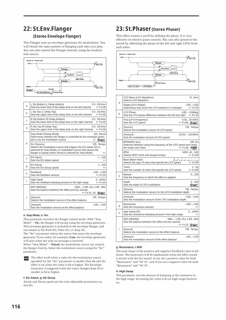
116
22: St.Env.Flanger(Stereo Envelope Flanger)
This Flanger uses an envelope generator for modulation. You will obtain the same pattern of flanging each time you play. You can also control the Flanger directly using the modula-tion source.
e: Swp Mode, e: SrcThis parameter switches the flanger control mode. With “Swp Mode” = EG, the flanger will sweep using the envelope generator. This envelope generator is included in the envelope flanger, and not related to the Pitch EG, Filter EG, or Amp EG.The “Src” parameter selects the source that starts the envelope generator. If you select, for example, Gate, the envelope generator will start when the note-on message is received.When “Swp Mode” = Dmod, the modulation source can control the flanger directly. Select the modulation source using the “Src” parameter.
The effect is off when a value for the modulation source specified for the “Src” parameter is smaller than 64, and the effect is on when the value is 64 or higher. The Envelope Generator is triggered when the value changes from 63 or smaller to 64 or higher.
f: EG Attack, g: EG DecayAttack and Decay speed are the only adjustable parameters on this EG.
23: St.Phaser (Stereo Phaser)
This effect creates a swell by shifting the phase. It is very effective on electric piano sounds. You can add spread to the sound by offsetting the phase of the left and right LFOs from each other.
g: Resonance, i: W/DThe peak shape of the positive and negative Feedback value is dif-ferent. The harmonics will be emphasized when the effect sound is mixed with the dry sound, if you set a positive value for both “Resonance” and “W/D”, and if you set a negative value for both “Resonance” and “W/D”.
h: High DampThis parameter sets the amount of damping of the resonance in the high range. Increasing the value will cut high-range harmon-ics.
a L Dly Bottom (L Delay Bottom) 0.0...50.0msSets the lower limit of the delay time on the left channel ☞ Fx:09
b L Dly Top (L Delay Top) 0.0...50.0msSets the upper limit of the delay time on the left channel ☞ Fx:09
c R Dly Bottom (R Delay Bottom) 0.0...50.0msSets the lower limit of the delay time on the right channel ☞ Fx:09
d R Dly Top (R Delay Top) 0.0...50.0msSets the upper limit of the delay time on the right channel ☞ Fx:09
e
Swp Mode (Sweep Mode) EG, DmodDetermines whether the flanger is controlled by the envelope gener-ator or by the modulation source ☞,
Src (Source) Off...TempoSelects the modulation source that triggers the EG (when EG is selected for Swp Mode), or modulation source that causes the flanger to sweep (when Dmod is selected for Swp Mode) ☞
f EG AttackSets the EG attack speed
1...100☞
g EG DecaySets the EG decay speed
1...100☞
h FeedbackSets the feedback amount
–100...+100☞ Fx:20
i High Damp 0...100%Sets the feedback damping amount in the high range ☞ Fx:20
j
W/D (Wet/Dly) –Wet...–1:99, Dry, 1:99...WetSets the balance between the effect and dry sounds
☞ Fx:10, 20,
(Source) Off...TempoSelects the modulation source of the effect balance
(Amount)Sets the modulation amount of the effect balance
–100...+100
EG Attack/DecayEG
D-mod
Sweep ModeD-mod
Flanger
Flanger
Left
Right
Feedback
Wet / Dry
Wet / Dry
High Damp
Stereo In - Stereo Out
a
LFO Wave (LFO Waveform)Selects LFO Waveform
Tri, Sine
Shape (LFO Shape) –100...+100Determines how much the LFO waveform is changed ☞ Fx:20
b LFO Phase –180...+180degSets the LFO phase difference between the left and right ☞ Fx:10
c
Freq (LFO Frequency) 0.02...20.00HzSets the LFO speed ☞ Fx:09,
(Source)Selects the modulation source of LFO speed
Off...Tempo
(Amount) –20.00...+20.00HzSets the modulation amount of LFO speed
d
BPM/MIDI Sync Off, OnSwitches between using the frequency of the LFO speed and using the tempo and notes ☞ Fx:09,
BPM MIDI, 40...240Selects MIDI Clock and assigns tempo ☞ Fx:09
Base (Base Note) � � � � � � � � � � � � � � � � � �Selects the type of notes that specify the LFO speed ☞ Fx:09
Times 1...16Sets the number of notes that specify the LFO speed ☞ Fx:09
e ManualSets the frequency to which the effect is applied
0...100
f
DepthSets the depth of LFO modulation
0...100
(Source) Off...TempoSelects the modulation source for the LFO modulation depth
(Amount) –100...+100Sets the modulation amount of the LFO modulation depth
g ResonanceSets the resonance amount
–100...+100☞
h High Damp [%] 0...100%Sets the resonance damping amount in the high range ☞
i
W/D (Wet/Dly) –Wet...–1:99, Dry, 1:99...WetSets the balance between the effect and dry sounds
☞ Fx:10,
(Source) Off...TempoSelects the modulation source of the effect balance
(Amount)Sets the modulation amount of the effect balance
–100...+100
Left
Right
Resonance
LFO Shape
LFO Phase
LFO: Tri / Sine
Wet / Dry
Wet / Dry
High Damp
Stereo In - Stereo Out
Phaser
Phaser

EFFE
CT
24: St.Rndm Phasr (Stereo Random Phaser)
This is a stereo phaser. The effect uses a step-shape waveform and random LFO for modulation, creating a unique phasing effect.
25: St.Env.Phaser(Stereo Envelope Phaser)
This stereo phaser uses an envelope generator for modula-tion. You will obtain the same pattern of phasing each time you play. You can also control the Phaser directly using the modulation source.
a LFO Wave (LFO Waveform) Step-Tri, Step-Sin, RandomSelects LFO Waveform ☞ Fx:10
b LFO Phase –180...+180degSets the LFO phase difference between the left and right ☞ Fx:10
c
Freq (LFO Frequency) 0.02...20.00HzSets the LFO speed ☞ Fx:10,
(Source) Off...TempoSelects the modulation source commonly used for LFO speed and step speed
(Amount) –20.00...+20.00HzSets the modulation amount of LFO speed
d
Freq (LFO Step Frequency) 0.05...50.00HzSets the LFO step speed ☞ Fx:10,
(Amount) –50.00...+50.00HzSets the modulation amount of LFO step speed
e
ManualSets the frequency to which the effect is applied
0...100
DepthSets the depth of LFO modulation
0...100
f
BPM/MIDI Sync Off, OnSwitches between using the frequency of the LFO speed and using the tempo and notes ☞ Fx:09,
BPMSelects MIDI Clock and assigns tempo
MIDI, 40...240 Fx:09, 10
Base (Base Note) � � � � � � � � � � � � � � � � � �Selects the type of notes that specify the LFO speed ☞ Fx:09
Times 1...16Sets the number of notes that specify the LFO speed ☞ Fx:09
g
Step Base (Step Base Note � � � � � � � � � � � � � � � � � � � � � � �Selects the type of notes to specify the LFO step speed
☞ Fx:10,
Times 1...32Sets the number of notes to specify the LFO step speed ☞ Fx:10
h
Resonanc (Resonance)Sets the resonance amount
–100...+100☞ Fx:23
HiDamp (High Damp) 0...100%Sets the resonance damping amount in the high range ☞ Fx:23
i
W/D (Wet/Dly) –Wet...–1:99, Dry, 1:99...WetSets the balance between the effect and dry sounds
☞ Fx:10, 23,
(Source) Off...TempoSelects the modulation source of the effect balance
(Amount)Sets the modulation amount of the effect balance
–100...+100
LFO: Step-Tri/Random
Left
Right
Resonance
LFO Phase
Wet / Dry
Wet / Dry
High Damp
Stereo In - Stereo Out
Phaser
Phaser
aL Manu Bottom (L Manual Bottom) 0...100Sets the lower limit of the frequency range for the effect on the left channel ☞ Fx:09
bL Manu Top (L Manual Top) 0...100Sets the upper limit of the frequency range for the effect on the left channel ☞ Fx:09
cR Manu Bottom (R Manual Bottom) 0...100Sets the lower limit of the frequency range for the effect on the right channel ☞ Fx:09
dR Manu Top (R Manual Top) 0...100Sets the upper limit of the frequency range for the effect on the right channel ☞ Fx:09
e
Swp Mode (Sweep Mode) EG, DmodDetermines whether the flanger is controlled by the envelope gener-ator or by the modulation source ☞ Fx:22,
Src (Source) Off...TempoSelects the modulation source that triggers the EG (when EG is selected for Swp Mode), or modulation source that causes the flanger to sweep (when Dmod is selected for Swp Mode)
f EG AttackSets the EG attack speed
1...100☞ Fx:22
g EG DecaySets the EG decay speed
1...100☞ Fx:22
h ResonanceSets the resonance amount
–100...+100☞ Fx:23
i High Damp 0...100%Sets the resonance damping amount in the high range ☞ Fx:23
j
W/D (Wet/Dly) –Wet...–1:99, Dry, 1:99...WetSets the balance between the effect and dry sounds
☞ Fx:10, 23,
(Source) Off...TempoSelects the modulation source of the effect balance
(Amount)Sets the modulation amount of the effect balance
–100...+100
EG Attack/DecayEG
D-mod
Sweep ModeD-mod
Phaser
Phaser
Left
Right
Resonance
Wet / Dry
Wet / Dry
High Damp
Stereo In - Stereo Out
117

118
26: St.BiphaseMod(Stereo Biphase Modulation)
This stereo chorus effect adds two different LFOs together. You can set the Frequency and Depth parameters for each LFO individually. Depending on the setting of these LFOs, very complex waveforms will create an analog-type, unstable modulated sound.
27: St.Vibrato (Stereo Vibrato)
This effect causes the pitch of the input signal to shimmer. Using the AutoFade allows you to increase or decrease the shimmering speed.
b: LFO Freq Mod, f: AUTOFADE Src, g: Fade Rate, g: DlyWhen “LFO Freq Mod” is set to AUTOFADE, you can use the modulation source selected in “AUTO FADE Src” as a trigger to automatically fade in the modulation amount. When “BPM/MIDI Sync” is set to On, you cannot use this.The “Fade Rate” parameter specifies the rate of fade-in. The “Dly” parameter determines the time from AutoFade modulation source ON until the fade-in starts.
The following is an example of fade-in where the LFO speed is increased from “1.0Hz” to “4.0Hz” when a note-on message is received.
“AUTOFADE Src”=Gate1, “Freq”=1.00 Hz“LFO Freq Mod”=AUTOFADE, “(Amount)”=+3.00
a LFO1 Wave (LFO1 Waveform)Selects LFO1 waveform
Triangle, Sine
b LFO2 Wave (LFO2 Waveform)Selects LFO2 waveform
Triangle, Sine
c LFO Phase Sw 0, 180degreeSwitches the LFO phase difference between left and right
d
F1 (LFO1 Frequency)Sets the LFO1 speed
0.02...30.00Hz
(Source)Selects the modulation source of LFO1&2 speed
Off...Tempo
(Amount)Sets the modulation amount of LFO1 speed
–30.00...+30.00
e
F2 (LFO2 Frequency)Sets the LFO2 speed
0.02...30.00Hz
(Amount)Sets the modulation amount of LFO2 speed
–30.00...+30.00
f
L Dly (L Pre Delay)Sets the delay time for the left channel
0.0...50.0ms☞ Fx:16
R Dly (R Pre Delay)Sets the delay time for the right channel
0.0...50.0ms☞ Fx:16
g
Depth1Sets the depth of LFO1 modulation
0...100
(Source) Off...TempoSelects the modulation source of LFO1&2 modulation depth
(Amount) –100...+100Sets the modulation amount of LFO1 modulation depth
h
Depth2Sets the depth of LFO2 modulation
0...100
(Amount) –100...+100Sets the modulation amount of LFO2 modulation depth
i
FeedbackSets the feedback amount
–100...+100☞ Fx:17
HiDamp (High Damp)Sets the damping amount in the high range
0...100%
j
W/D (Wet/Dly) –Wet...–1:99, Dry, 1:99...WetSets the balance between the effect and dry sounds
☞ Fx:10,
(Source) Off...TempoSelects the modulation source of the effect balance
(Amount)Sets the modulation amount of the effect balance
–100...+100
Chorus/Flanger
Left
Right
Feedback
180 [degree]
Wet / Dry
Wet / Dry
High Damp
Stereo In - Stereo Out
LFO1: Tri / Sine
LFO2: Tri / Sine
Chorus/Flanger
High Damp
LFO1
LFO2
Bi-Phase Modulation LFO
Depth1
Depth2
+
a
LFO Wave (LFO Waveform)Selects LFO Waveform
Triangle, Sine
Shape (LFO Shape) –100...+100Determines how much the LFO waveform is changed ☞ Fx:20
bLFO Freq Mod (LFO Frequency Mod) Dmod, AUTOFADESwitches between Dmod and AUTOFADE for the LFO frequency modulation ☞
c
Freq (LFO Frequency) 0.02...20.00HzSets the LFO speed ☞ Fx:09,
(Source)Selects the modulation source of LFO speed
Off...Tempo
(Amount) –20.00...+20.00HzSets the modulation amount of LFO speed
d
BPM/MIDI Sync Off, OnSwitches between using the frequency of the LFO speed and using the tempo and notes ☞ Fx:09,
BPMSelects MIDI Clock and assigns tempo
MIDI, 40...240☞ Fx:09
Base (Base Note) � � � � � � � � � � � � � � � � � �Selects the type of notes that specify the LFO speed ☞ Fx:09
Times 1...16Sets the number of notes that specify the LFO speed ☞ Fx:09
e
DepthSets the depth of LFO modulation
0...100
(Source) Off...TempoSelects the modulation source of the LFO modulation depth
(Amount) –100...+100Sets the modulation amount of the LFO modulation depth
f AUTOFADE Src (AUTOFADE Source) Off...TempoSelects the modulation source that starts AutoFade ☞,
g
Fade Rate (Fade-In Rate)Sets the rate of fade-in
1...100☞
Dly (Fade-In Delay)Sets the fade-in delay time
00...2000ms☞
h
W/D (Wet/Dly) Dry, 1:99...99:1, WetSets the balance between the effect and dry sounds
(Source) Off...TempoSelects the modulation source of the effect balance
(Amount)Sets the modulation amount of the effect balance
–100...+100
Vibrato
Vibrato
Left
Right
Wet / Dry
Wet / Dry
Stereo In - Stereo Out
LFO: Tri / Sine LFO Shape
Fade-In Delay LFO FrequencyAutoFade

EFFE
CT
The effect is off when a value for the dynamic modulation source specified for the “AUTOFADE Src” parameter is smaller than 64, and the effect is on when the value is 64 or higher. The AutoFade function is triggered when the value changes from 63 or smaller to 64 or higher.
28: St.AutoFd Mod(Stereo Auto Fade Modulation)
This stereo chorus/flanger effect enables you to control the LFO speed and effect balance using auto fade, and you can spread the sound by offsetting the phase of the left and right LFOs from each other.
29: 2Voice Reso (2Voice Resonator)
This effect resonates the input signal at a specified pitch. You can set the pitch, output level, and pan settings for two reso-nators individually. You can control the resonance intensity via an LFO.
a
LFO Wave (LFO Waveform)Selects LFO Waveform
Tri, Sine
Shape (LFO Shape) –100...+100Determines how much the LFO waveform is changed ☞ Fx:20
b LFO Phase –180...+180degSets the LFO phase difference between the left and right ☞ Fx:10
c
Freq (LFO Frequency)Sets the LFO speed
0.02...20.00Hz
(Source)Selects the modulation source of LFO speed
Off...Tempo
(Amount) –20.00...+20.00HzSets the modulation amount of LFO speed
d
L Dly (L Pre Delay)Sets the left channel delay time
0.0...500.0ms
R Dly (R Pre Delay)Sets the right channel delay time
0.0...500.0ms
e
Dep (Depth)Sets the depth of LFO modulation
0...200
Fb (Feedback)Sets the feedback amount
–100...+100☞ Fx:20
HD (High Damp) 0...100%Sets the feedback damping amount in the high range ☞ Fx:20
fAUTOFADE Src (AUTOFADE Source) Off...TempoSelects the modulation source that starts AutoFade
☞ Fx:27,
g
Fade Rate (Fade-In Rate)Sets the rate of fade-in
1...100☞ Fx:27
Dly (Fade-In Delay)Sets the fade-in delay time
00...2000ms☞ Fx:27
hFreq Mod (LFO Frequency Mod) D-mod, AUTOFADESwitches between D-mod and AUTOFADE for the LFO frequency modulation ☞ Fx:27
iW/D Mod (Wet/Dry Mod) D-mod, AUTOFADESwitches between D-mod and AUTOFADE for the effect balance modulation ☞ Fx:27
AUTOFADE AutoFade
Note On All Note Off
Fade-In Rate
AUTOFADE Src=Gate1LFO Frequency[Hz]=1.00LFO Freq. Mod=AUTOFADEAmt=+3.00
LFO Frequency=1.0+3.0=4.0Hz
LFO Frequency=1.0Hz
Gate1 Signal
AUTOFADEFade-In Delay
AutoFade LFO Frequency
Wet / Dry
Delay
Delay
Left
Right
Feedback
LFO Shape
LFO Phase
LFO: Tri / Sine
Wet / Dry
Wet / Dry
High Damp
Stereo In - Stereo Out
j
W/D (Wet/Dly) –Wet...–1:99, Dry, 1:99...WetSets the balance between the effect and dry sounds
☞ Fx:10, 20,
(Source) Off...TempoSelects the modulation source of the effect balance
(Amount)Sets the modulation amount of the effect balance
–100...+100
a
Ctrl (Control Mode) Manual, LFO, DmodSwitches the controls of resonance intensity ☞,
Invert (LFO/Dmod Invert) Off, OnReverses the Voice 1 and 2 control when LFO/Dmod is selected
☞
b
lfoF (LFO Frequency)Sets the LFO speed
0.02...20.00Hz
Dmod (Dmod Source) Off...TempoSelects the modulation source that controls resonance intensity
c
Mod Dep (Mod Depth) –100...+100Sets the amount of resonance intensity control via LFO/Dmod
TrimSets the input level at the resonator
0...100
d
V1 Pitch (Voice1 Pitch)Sets the voice1 Pitch for resonance
C0...B8
Fine –50...+50centFine-adjusts the voice 1 pitch for resonance
e
V1 Reso (Voice1 Resonance) –100...+100Sets the intensity of resonance when Control Mode = Manual ☞
HiDamp (High Damp) 0...100%Sets the damping amount of resonant sound in the high range ☞
f
V1 Level (Voice1 Level)Sets the Voice1 output level
0...100
PanSets the Voice1 stereo image
L6...R6
g
V2 Pitch (Voice2 Pitch)Sets the Voice2 Pitch for resonance
C0...B8
FineFine-adjusts the voice 2 pitch for resonance
–50...+50cent
h
V2 Reso (Voice2 Resonance) –100...+100Sets the intensity of resonance when Control Mode = Manual ☞
HiDamp (High Damp) 0...100%Sets the damping amount of resonant sound in the high range ☞
i
V2 Level (Voice2 Level)Sets the Voice2 output level
0...100
PanSets the Voice2 stereo image
L6...R6
j
W/D (Wet/Dly) Dry, 1:99...99:1, WetSets the balance between the effect and dry sounds
(Source) Off...TempoSelects the modulation source of the effect balance
(Amount)Sets the modulation amount of the effect balance
–100...+100
Left
Right
Resonance
Wet / Dry
Wet / Dry
Wet: Mono In - Stereo Out / Dry: Stereo In - Stereo Out
High Damp
High DampTrim
Trim
+
Level
Level Pan
Pan
Control Mode
D-mod
LFO
Manual
Invert: On/Off
Resonator
Resonator
Pitch, Fine [cent]
119

120
a: Ctrl, e: V1 Reso, h: V2 ResoThis parameter determines the resonance intensity.When “Ctrl” = Manual, the “Reso” parameter sets the intensity of resonance. If the “Reso” parameter has a negative value, harmon-ics will be changed, and resonance will occur at a pitch one octave lower.When “Ctrl” = LFO, the intensity of resonance varies according to the LFO. The LFO sways between positive and negative values, causing resonance to occur between specified pitches an octave apart in turn.When “Ctrl” = Dmod, the resonance is controlled by the dynamic modulation source. If JS X or Rbn#16 is assigned as the modula-tion source, the pitch an octave higher and lower can be con-trolled, similar to when LFO is selected for Control Mode.
a: InvertWhen “Ctrl” = LFO or Dmod, the controlled phase of either Voice 1 or 2 will be reversed. When the resonance pitch is set for Voice 1 (Resonance has a positive value), Voice 2 will resonate at a pitch an octave below (Resonance has a negative value).
d: V1 Pitch, d: Fine, g: V2 Pitch, g: FineThe Pitch parameter specifies the pitch of resonance by note name. The “Fine” parameter allows for fine adjustment in steps of cents.
e: HiDamp, h: HiDampThis parameter sets the damping amount of resonant sound in the high range. Lower values will make a metallic sound with a higher range of harmonics.
30: DopplerThis effect simulates the “Doppler effect” of a moving sound with a changing pitch, similar to the siren of an passing ambulance. Mixing the effect sound with the dry sound will create a unique chorus effect.
a: Mode, a: Src, b: LFO SyncThe “Mode” parameter switches LFO operation mode. When Loop is selected, the Doppler effect will be created repeatedly. If “LFO Sync” is set to On, the LFO will be reset when the modula-tion source specified with the “Src” parameter is turned on.When “Mode” is set to 1-Shot, the Doppler effect is created only once when the modulation source specified in the “Src” field is turned on. At this time if you do not set the “Src” parameter, the Doppler effect will not be created, and no effect sound will be out-put.
The effect is off when a value for the modulation source specified for the “Src” parameter is smaller than 64, and the effect is on when the value is 64 or higher. The Doppler effect is triggered when the value changes from 63 or smaller to 64 or higher.
e: Pitch DepWith the Doppler effect, the pitch is raised when the sound approaches, and the pitch is lowered when the sound goes away. This parameter sets this pitch variation.
f: Pan DepThis parameter sets the width of the stereo image of the effect sound. With larger values, the sound seems to come and go from much further away. With positive values, the sound moves from left to right; with negative values, the sound moves from right to left.
a
Mode (LFO Mode)Switches LFO operation mode
Loop, 1-Shot☞,
Src (Source) Off...TempoWhen LFO Mode is set to 1-Shot, this modulation source triggers the LFO ☞
bLFO Sync Off, OnSwitches between LFO reset on and off when LFO Mode is set to Loop ☞
c
Freq (LFO Frequency) 0.02...20.00HzSets the LFO speed ☞ Fx:09,
(Source)Selects the modulation source of LFO speed
Off...Tempo
(Amount) –20.00...+20.00HzSets the modulation amount of LFO speed
d
BPM/MIDI Sync Off, OnSwitches between using the frequency of the LFO speed and using the tempo and notes ☞ Fx:09,
BPMSelects MIDI Clock and assigns tempo
MIDI, 40...240☞ Fx:09
Base (Base Note) � � � � � � � � � � � � � � � � � �Selects the type of notes that specify the LFO speed ☞ Fx:09
Times 1...16Sets the number of notes that specify the LFO speed ☞ Fx:09
Left
Right
Wet / Dry
Wet / Dry
Wet: Mono In - Stereo Out / Dry: Stereo In - Stereo Out
Pan Depth
D-mod
+
Trigger LFO Mode = 1-Shot
Doppler
LFO
e
Pitch Dep (Pitch Depth)Sets the pitch variation of the moving sound
0...100☞,
(Source)Selects the modulation source of pitch variation
Off...Tempo
(Amount)Sets the modulation amount of pitch variation
–100...+100
f
Pan Dep (Pan Depth)Sets the panning of the moving sound
–100...+100☞,
(Source)Selects the modulation source of panning
Off...Tempo
(Amount)Sets the modulation amount of panning
–100...+100
g
W/D (Wet/Dly) Dry, 1:99...99:1, WetSets the balance between the effect and dry sounds
(Source) Off...TempoSelects the modulation source of the effect balance
(Amount)Sets the modulation amount of the effect balance
–100...+100
Pitch
Hig
her
Doppler - Pitch / Pan Depth
Lo
wer
Original Pitch
Left Center Right
Pitch Depth
Pan Depth< < < < < <<<<<< >>>>>> > > > > >
VolumeLouder Louder
Pan Depth= (–) value
Pan Depth= (+) value
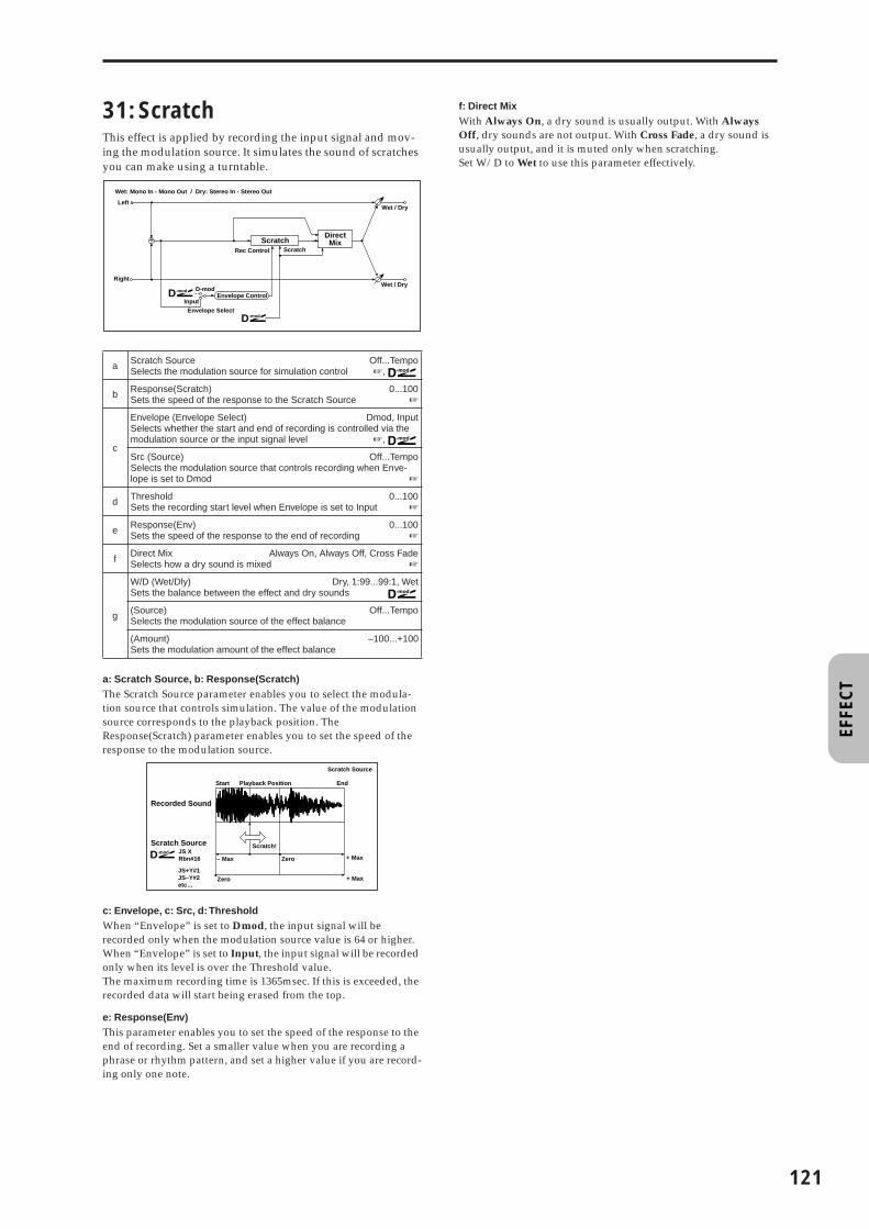
EFFE
CT
31: ScratchThis effect is applied by recording the input signal and mov-ing the modulation source. It simulates the sound of scratches you can make using a turntable.
a: Scratch Source, b: Response(Scratch)The Scratch Source parameter enables you to select the modula-tion source that controls simulation. The value of the modulation source corresponds to the playback position. The Response(Scratch) parameter enables you to set the speed of the response to the modulation source.
c: Envelope, c: Src, d: ThresholdWhen “Envelope” is set to Dmod, the input signal will be recorded only when the modulation source value is 64 or higher.When “Envelope” is set to Input, the input signal will be recorded only when its level is over the Threshold value.The maximum recording time is 1365msec. If this is exceeded, the recorded data will start being erased from the top.
e: Response(Env)This parameter enables you to set the speed of the response to the end of recording. Set a smaller value when you are recording a phrase or rhythm pattern, and set a higher value if you are record-ing only one note.
f: Direct MixWith Always On, a dry sound is usually output. With Always Off, dry sounds are not output. With Cross Fade, a dry sound is usually output, and it is muted only when scratching.Set W/D to Wet to use this parameter effectively.
a Scratch Source Off...TempoSelects the modulation source for simulation control ☞,
b Response(Scratch) 0...100Sets the speed of the response to the Scratch Source ☞
c
Envelope (Envelope Select) Dmod, InputSelects whether the start and end of recording is controlled via the modulation source or the input signal level ☞,
Src (Source) Off...TempoSelects the modulation source that controls recording when Enve-lope is set to Dmod ☞
d Threshold 0...100Sets the recording start level when Envelope is set to Input ☞
e Response(Env) 0...100Sets the speed of the response to the end of recording ☞
f Direct Mix Always On, Always Off, Cross FadeSelects how a dry sound is mixed ☞
g
W/D (Wet/Dly) Dry, 1:99...99:1, WetSets the balance between the effect and dry sounds
(Source) Off...TempoSelects the modulation source of the effect balance
(Amount)Sets the modulation amount of the effect balance
–100...+100
Input
D-mod
Envelope Select
D-modEnvelope Control
Left
Right
Wet / Dry
Wet / Dry
Wet: Mono In - Mono Out / Dry: Stereo In - Stereo Out
+ ScratchDirect
Mix
D-mod
Rec Control Scratch
+ MaxZero
Scratch!
D-mod
– MaxJS XRbn#16
JS+Y#1JS–Y#2etc…
Zero + Max
Scratch Source
Recorded Sound
Scratch Source
Start Playback Position End
121

122
Mod./P.Shift
Other modulation and pitch shift effects
32: St.Tremolo (Stereo Tremolo)
This effect modulates the volume level of the input signal. The effect is stereo, and offsetting the LFO of the left and right phases from each other produces a tremolo effect between left and right.
a: LFO WaveThis parameter selects the LFO waveform. Vintg (Vintage) wave simulates the characteristics of the tremolo created on a guitar amplifier. Combining this effect with the Amp Simulation will make a realistic, vintage tremolo amplifier sound.
b: LFO PhaseThis parameter determines the difference between the left and right LFO phases. A higher value will simulate the auto-pan effect in which the sound is panned between left and right.
33: St.Env.Tremlo(Stereo Envelope Tremolo)
This effect uses the input signal level to modulate a stereo tremolo. You can simulate a tremolo effect that becomes deeper as it fades out while the level gets lower.
e: Freq, e: (Envelope Amount), f: Depth, f: (Envelope Amount)These parameters set the modulation via an envelope (input sig-nal level).The “LFO speed” is obtained by adding the “Freq” value to the “(Envelope Amount)” value multiplied by the input signal. The LFO modulation depth is obtained by adding the Depth value to the “(Envelope Amount)” value multiplied by the input signal level.• The following example indicates that the “Depth” is 0 with an
LFO Frequency of 1.0Hz and the maximum input, and that the “Depth” is 100 with a Frequency of 8.0 Hz with zero input.“Freq”=8.00 Hz, “Envelope Amount”=–7.00“Depth”=100, “Envelope Amount”=–100
a
LFO Wave (LFO Waveform) Tri, Sine, Vintg, Up, DownSelects LFO Waveform ☞
Shape (LFO Shape) –100...+100Determines how much the LFO waveform is changed ☞ Fx:20
b LFO Phase –180...+180degSets the LFO phase difference between the left and right ☞
c
Freq (LFO Frequency) 0.02...20.00HzSets the LFO speed ☞ Fx:09,
(Source)Selects the modulation source of LFO speed
Off...Tempo
(Amount) –20.00...+20.00HzSets the modulation amount of LFO speed
d
BPM/MIDI Sync Off, OnSwitches between using the frequency of the LFO speed and using the tempo and notes ☞ Fx:09,
BPMSelects MIDI Clock and assigns tempo
MIDI, 40...240☞ Fx:09
Note (Base Note) � � � � � � � � � � � � � � � � � �Selects the type of notes that specify the LFO speed ☞ Fx:09
Times 1...16Sets the number of notes that specify the LFO speed ☞ Fx:09
e
DepthSets the depth of LFO modulation
0...100
(Source) Off...TempoSelects the modulation source of the depth of modulation
(Amount) –100...+100Sets the modulation amount of the depth of modulation
f
W/D (Wet/Dly) Dry, 1:99...99:1, WetSets the balance between the effect and dry sounds
(Source) Off...TempoSelects the modulation source of the effect balance
(Amount)Sets the modulation amount of the effect balance
–100...+100
Left
Right
Wet / Dry
Wet / Dry
Stereo In - Stereo Out
LFO Phase
LFO: Tri/Sin/Vintage/Up/Down LFO Shape
Tremolo
Tremolo
Tremolo - LFO Waveform
Triangle Sine Vintage Up Down
a Envelope Sens (Envelope Sensitivity)Sets the envelope sensitivity of the input signal
0...100
bEnvelope ShapeSets the envelope curve shape of the input sig-nal
–100...+100
c
LFO Wave (LFO Waveform) Tri, Sine, VintgSelects LFO Waveform
Shape (LFO Shape) –100...+100Determines how much the LFO waveform is changed ☞ Fx:20
d LFO Phase –180...+180degSets the LFO phase difference between the left and right ☞ Fx:32
e
Freq (LFO Frequency)Sets the LFO speed
0.02...20.00Hz☞
(Envelope Amount) –20.00...+20.00HzSets the changes of the LFO speed according to the input signal level ☞
f
DepthSets the depth of LFO modulation
0...100☞
(Envelope Amount) –100...+100Sets the changes of the modulation depth according to the input sig-nal level ☞
g
W/D (Wet/Dly) Dry, 1:99...99:1, WetSets the balance between the effect and dry sounds
(Source) Off...TempoSelects the modulation source of the effect balance
(Amount)Sets the modulation amount of the effect balance
–100...+100
Left
Right
Wet / Dry
Wet / Dry
Stereo In - Stereo Out
LFO Phase
LFO Shape
Envelope Sens+ Envelope
LFO: Tri/Sin/Vintage
Envelope Shape
Tremolo
Tremolo

EFFE
CT
34: St.Auto Pan (Stereo Auto Pan)
This Auto Pan effect pans sound between left and right. It is stereo, and shifting the left and right LFO phases from each other will simulate the sound of the left and right channels crossing over each other by turns, or chasing each other.
a: ShapeYou can change the panning curve by modifying the LFO wave-form.
b: LFO PhaseThis parameter determines the difference in the left and right LFO phases. When you change the value gradually from 0, the sound from the left and right channels will chase each other around. If you set the parameter to +180 or –180, the sound from each chan-nel will cross over each other.
You need to input different sounds to each channel in order for this parameter to be effective.
35: St.Phasr+Trml(Stereo Phaser + Tremolo)
This effect has a stereo phaser and tremolo LFOs linked together. Swelling phaser modulation and tremolo effects synchronize with each other, creating a soothing modulation effect. It is suitable for electric piano type sounds.
a
LFO Wave (LFO Waveform)Selects LFO Waveform
Tri, Sine
Shape (LFO Shape) –100...+100Determines how much the LFO waveform is changed ☞
b LFO Phase –180...+180degSets the LFO phase difference between the left and right ☞
c
Freq (LFO Frequency) 0.02...20.00HzSets the LFO speed ☞ Fx:09,
(Source)Selects the modulation source of LFO speed
Off...Tempo
(Amount) –20.00...+20.00HzSets the modulation amount of LFO speed
d
BPM/MIDI Sync Off, OnSwitches between using the frequency of the LFO speed and using the tempo and notes ☞ Fx:09,
BPMSelects MIDI Clock and assigns tempo
MIDI, 40...240☞ Fx:09
Base (Base Note) � � � � � � � � � � � � � � � � � �Selects the type of notes that specify the LFO speed ☞ Fx:09
Times 1...16Sets the number of notes that specify the LFO speed ☞ Fx:09
e
DepthSets the depth of LFO modulation
0...100
(Source) Off...TempoSelects the modulation source of the depth of modulation
(Amount)Sets the modulation amount of the depth of mod-ulation
–100...+100
f
W/D (Wet/Dly) Dry, 1:99...99:1, WetSets the balance between the effect and dry sounds
(Source) Off...TempoSelects the modulation source of the effect balance
(Amount)Sets the modulation amount of the effect balance
–100...+100
Level
Lo
ud
er
Time
Shimmer
LFO Frequency[Hz]=8.00Envelope Amount= –7.00Depth=100Envelope Amount= –100
Dry Envelope
Left
Right
Wet / Dry
Wet / Dry
Stereo In - Stereo Out
LFO Phase
LFO Shape
Pan
Pan
LFO: Tri / Sin
Depth
a Type: Phs - Trml...Phs LR - Trml LRSelects the type of the tremolo and phaser LFOs ☞
bLFO Phase –180...+180degSets the phase difference between the tremolo and phaser LFOs
☞
c
Freq (LFO Frequency) 0.02...20.00HzSets the LFO speed ☞ Fx:09,
(Source)Selects the modulation source of LFO speed
Off...Tempo
(Amount) –20.00...+20.00HzSets the modulation amount of LFO speed
d
BPM/MIDI Sync Off, OnSwitches between using the frequency of the LFO speed and using the tempo and notes ☞ Fx:09,
BPMSelects MIDI Clock and assigns tempo
MIDI, 40...240☞ Fx:09
Base (Base Note) � � � � � � � � � � � � � � � � � �Selects the type of notes that specify the LFO speed ☞ Fx:09
Times 1...16Sets the number of notes that specify the LFO speed ☞ Fx:09
e
P Manu (Phaser Manual)Sets the phaser frequency range
0...100
Resonanc (Resonance)Sets the phaser resonance amount
–100...+100
f
P Dep (Phaser Depth)Sets the phaser modulation depth
0...100
(Source) Off...TempoSelects the modulation source for the phaser modulation depth
(Amount) –100...+100Sets the modulation amount for the phaser modulation depth
g
P W/D (Phaser W/D) –Wet...–2:99, Dry, 2:99...WetSets the balance between the phaser effect and dry sounds ☞
T Shape (Tremolo Shape)Sets the degree of the tremolo LFO shaping
–100...+100☞ Fx:20
L-In
Left Center RightOutput Stereo Image
R-In
L-In
R-In
L-In
R-In
L-In
R-In
L-In
R-In
L-In
R-In
L-In
R-In
L-In
R-In
L-In
R-In
L-In
R-In
L-In
R-In
L-In
R-In
L-In
R-In
L-In
R-In
L-In
R-In
LFO Phase = 0 degrees LFO Phase = 90 degrees LFO Phase = 180 degrees
Stereo Auto Pan - LFO Phase
Phaser
Phaser
Left
Right
Resonance
LFO Type
Wet / Dry
Wet / Dry
Stereo In - Stereo Out
Phaser Wet / Dry
Phaser Wet / Dry
LFOLFO Phase
LFO Shape
Tremolo
Tremolo
123

124
a: Type, b: LFO PhaseSelect the type of phaser LFO and tremolo LFO for the “Type” parameter. How the effect sound moves or rotates depends on the type of LFO. Selecting “LFO Phase” enables you to offset the tim-ing of the phaser peak and control a subtle movement and rota-tion of the sound.
f: P W/D, i: W/DThe “P W/D” parameter sets the balance between the phaser out-put and the dry sound. The “W/D” parameter sets the balance between the final phaser and tremolo output level and the dry sound.
36: St.Ring Mod(Stereo Ring Modulator)
This effect creates a metallic sound by applying the oscillators to the input signal. Use the LFO or Dynamic Modulation to modulate the oscillator to create a radical modulation. Match-ing the oscillator frequency with a note number will produce a ring modulation effect in specific key ranges.
a: Pre LPFThis parameter enables you to set the damping amount of the high range sound input to the ring modulator. If the input sound contains lots of harmonics, the effect may sound dirty. In this case, cut a certain amount of high range.
b: OSC ModeThis parameter determines whether or not the oscillator fre-quency follows the note number.
c: FThis parameter sets the oscillator frequency when “OSC Mode” is set to Fixed.
d: Note Offset, d: FineThese parameters for the oscillator are used when “OSC Mode” is set to Note (Key Follow). The “Note Offset” sets the pitch differ-ence from the original note in semitone steps. The “Fine” parame-ter fine-adjusts the pitch in cent steps. Matching the oscillator frequency with the note number produces a ring modulation effect in the correct key.
h
T Dep (Tremolo Depth)Sets the tremolo modulation depth
0...100
(Source) Off...TempoSelects the modulation source for the tremolo modulation depth
(Amount) –100...+100Sets the modulation amount of the tremolo modulation depth
i
W/D (Wet/Dly) Dry, 1:99...99:1, WetSets the balance between the effect and dry sounds ☞,
(Source) Off...TempoSelects the modulation source of the effect balance
(Amount)Sets the modulation amount of the effect balance
–100...+100
aPre LPF 0...100Sets the damping amount of the high range input to the ring modula-tor ☞
bOSC Mode Fixed, Note (Key Follow)Switching between specifying the oscillator frequency and using a note number ☞
c
F (Fixed Frequency) 0...12.00kHzSets the oscillator frequency when OSC Mode is set to Fixed
☞,
(Source) Off...TempoSelects the modulation source for the oscillator frequency when OSC Mode is set to Fixed
(Amount) –12.00...+12.00kHzSets the modulation amount of the oscillator frequency when OSC Mode is set to Fixed
d
Note Offset –48...+48Sets the pitch difference from the original note when OSC Mode is set to Note (Key Follow) ☞
Fine (Note Fine)Fine-adjusts the oscillator frequency
–100...+100☞
Left
Right
Wet / Dry
Wet / Dry
Stereo In - Stereo Out
Pre LPF
Ring Modulator
Pre LPF
Ring Modulator
Note No.OSC Mode
Fixed
Note (Key Follow)
Fixed FrequencyPitch
Note Offset, Fine
Sine Oscillator
LFO
e
lfoF (LFO Frequency) 0.02...20.00HzSets the LFO speed of the oscillator frequency modulation
☞ Fx:09,
(Source)Selects the modulation source of LFO speed
Off...Tempo
(Amount) –20.00...+20.00HzSets the modulation amount of LFO speed
f
BPM/MIDI Sync Off, OnSwitches between using the frequency of the LFO speed and using the tempo and notes ☞ Fx:09,
BPMSelects MIDI Clock and assigns tempo
MIDI, 40...240☞ Fx:09
Base (Base Note) � � � � � � � � � � � � � � � � � �Selects the type of notes that specify the LFO speed ☞ Fx:09
Times 1...16Sets the number of notes that specify the LFO speed ☞ Fx:09
g
Depth (LFO Depth) 0...100Sets the depth of LFO modulation for the oscillator frequency
(Source) Off...TempoSelects the modulation source of the depth of modulation
(Amount) –100...+100Sets the modulation amount of the depth of modulation
h
W/D (Wet/Dly) Dry, 1:99...99:1, WetSets the balance between the effect and dry sounds
(Source) Off...TempoSelects the modulation source of the effect balance
(Amount)Sets the modulation amount of the effect balance
–100...+100

EFFE
CT
37: DetuneUsing this effect, you can obtain a detune effect that offsets the pitch of the effect sound slightly from the pitch of the input signal. Compared to the chorus effect, a more natural sound thickness will be created.
e: InLvl Mod, e: SrcThis parameter sets the dynamic modulation of the input level.
38: Pitch ShifterThis effect changes the pitch of the input signal. You can select from three types: Fast (quick response), Medium, and Slow (preserves tonal quality). You can also create an effect in which the pitch is gradually raised (or dropped) using the delay with feedback.
a: ModeThis parameter switches the pitch shifter operating mode. With Slow, tonal quality will not be changed too much. With Fast, the effect becomes a Pitch Shifter that has a quick response, but may change the tone. Medium is in between these two. If you do not need to set too much pitch shift amount, set this parameter to Slow. If you wish to change the pitch significantly, use Fast.
b: Shift, b: (Source), b: (Amount), c: Fine, c: (Amount)The amount of pitch shift will use the value of the “Shift” plus the “Fine” value. The amount of modulation will use the c: (Amount) value plus d: “(Amount).”Modulation Source is used both for “Shift” and “Fine.”
e: Feedback Position, f: FeedbackWhen “Feedback Position” is set to Pre, the pitch shifter output is again input to the pitch shifter. Therefore, if you specify a higher value for the Feedback parameter, the pitch will be raised (or low-ered) more and more each time feedback is repeated.If “Feedback Position” is set to Post, the feedback signal will not pass through the pitch shifter again. Even if you specify a higher value for the Feedback parameter, the pitch-shifted sound will be repeated at the same pitch.
a
Sft (Pitch Shift)Sets the pitch difference from the input signal
–100...+100cent
(Source)Selects the modulation source of the pitch shift
Off...Tempo
(Amount)Sets the modulation amount of the pitch shift
–100...+100cent
b Delay (Delay Time)Sets the delay time
0...1000ms
c FeedbackSets the feedback amount
–100...+100
d High DampSets the damping amount in the high range
0...100%
e
InLvl Mod (Input Level Dmod [%])Sets the modulation amount of the input level
–100...+100☞,
Src (Source)Selects the modulation source for the input level
Off...Tempo☞
f
W/D (Wet/Dly) Dry, 1:99...99:1, WetSets the balance between the effect and dry sounds
(Source) Off...TempoSelects the modulation source of the effect balance
(Amount)Sets the modulation amount of the effect balance
–100...+100
Left
Right
Wet / Dry
Wet / Dry
Wet: Mono In - Mono Out / Dry: Stereo In - Stereo Out
Input Level
Input Level
+High Damp
Delay
Feedback
Detune
Input Level
Lo
ud
er
MaxZero
Higher D-mod
Input Level
MaxZero
Higher D-mod
x1.0
x0.5
Amt= +100
Amt= +50
Lo
ud
er
x1.0
x0.5
Amt= –100
Amt= –50
Input Level D-mod
a Mode Slow, Medium, FastSwitches Pitch Shifter mode ☞
b
Shift (Pitch Shift) –24...+24Sets the pitch shift amount by steps of a semitone ☞,
(Source) Off...TempoSelects the modulation source of pitch shift amount ☞
(Amount)Sets the modulation amount of pitch shift amount
–24...+24☞
c
FineSets the pitch shift amount by steps of a cent
–100...+100cent☞,
(Amount)Sets the modulation amount of pitch shift amount
–100...+100cent☞
d Delay (Delay Time)Sets the delay time
0...1000ms
e Feedback PositionSwitches the feedback connection.
Pre, Post☞
f
FeedbackSets the feedback amount
–100...+100☞
HiDamp (High Damp)Sets the damping amount in the high range
0...100%
g
InLvl Mod (Input Level Dmod [%]) –100...+100Sets the modulation amount of the input level ☞ Fx:37,
Src (Source)Selects the modulation source for the input level
Off...Tempo☞ Fx:37
h
W/D (Wet/Dly) Dry, 1:99...99:1, WetSets the balance between the effect and dry sounds
(Source) Off...TempoSelects the modulation source of the effect balance
(Amount)Sets the modulation amount of the effect balance
–100...+100
Left
Right
Wet / Dry
Wet / Dry
Wet: Mono In - Mono Out / Dry: Stereo In - Stereo Out
Input Level
Input Level
+High Damp
Delay
Feedback
Pitch Shifter
Feedback Position
Pre Post
125

126
39: PitchShft Mod (Pitch Shift Modulation)
This effect modulates the detuned pitch shift amount using an LFO, adding a clear spread and width to the sound by pan-ning the effect sound and dry sound to the left and right. This is especially effective when the effect sound and dry sound output from stereo speakers are mixed.
a: Pitch Shift [cent], e: DepthThese parameters set the amount of pitch shift and amount of modulation by means of the LFO.
f: Pan, g: W/DThe Pan parameter pans the effect sound and dry sound to the left and right. With L, the effect sound is panned left, and the dry sound is panned right. With a W/D = Wet setting, the effect and dry sound will be output in a proportion of 1:1.
40: Rotary SP (Rotary Speaker)
This effect simulates a rotary speaker, and obtains a more real-istic sound by simulating the rotor in the low range and the horn in the high range separately. The effect also simulates the stereo microphone settings.
a: (Sw)This parameter sets how the modulation source switches between rotation and stop.When “Sw” = Tggl (Toggle), the speaker rotates or stops alter-nately each time you press the pedal.
Each time the value for the modulation source exceeds 64, the speaker rotates or stops alternately.
a Pitch ShiftSets the pitch difference from the input signal
–100...+100cent☞
b LFO Wave (LFO Waveform)Selects LFO Waveform
Triangle, Square
c
Freq (LFO Frequency) 0.02...20.00HzSets the LFO speed ☞ Fx:09,
(Source)Selects the modulation source of LFO speed
Off...Tempo
(Amount) –20.00...+20.00HzSets the modulation amount of LFO speed
d
BPM/MIDI Sync Off, OnSwitches between using the frequency of the LFO speed and using the tempo and notes ☞ Fx:09,
BPMSelects MIDI Clock and assigns tempo
MIDI, 40...240☞ Fx:09
Base (Base Note) � � � � � � � � � � � � � � � � � �Selects the type of notes that specify the LFO speed ☞ Fx:09
Times 1...16Sets the number of notes that specify the LFO speed ☞ Fx:09
e
Depth –100...+100Sets the LFO modulation depth for pitch shift amount ☞,
(Source) Off...TempoSelects the modulation source of the depth of modulation
(Amount) –100...+100Sets the modulation amount of the depth of modulation
f Pan L, 1:99...99:1, RSets the panning effect sound and dry sound separately ☞
g
W/D (Wet/Dly) Dry, 1:99...99:1, WetSets the balance between the effect and dry sounds ☞,
(Source) Off...TempoSelects the modulation source of the effect balance
(Amount)Sets the modulation amount of the effect balance
–100...+100
Left
Right
Wet / Dry
Wet / Dry
Wet: Mono In - Stereo Out / Dry: Stereo In - Stereo Out
LFO: Tri / Sqr
Pitch Shifter
Pan
+
Pitch
Hig
her
Pitch Shift Mod - Pitch Shift / Depth
Lo
wer
Original PitchPitch Shift (+ value)
LFO Waveform=TriangleDepth (+value)
LFO Waveform=SquareDepth (–value)
a
Mode (Mode Switch)Switches between speaker rotation and stop
Rotate, Stop
(Source) Off...TempoSelects the modulation source that toggles between rotation and stop
(Sw) Tggl, MmntSelects switching mode of the modulation source that toggles between rotation and stop ☞
b
Speed (Speed Switch) Slow, FastSwitches the speaker rotation speed between slow and fast
(Source) Off...TempoSelects the modulation source that toggles between slow and fast
(Sw) Tggl, MmntSelects switching mode of the modulation source that toggles between slow and fast ☞
c
H/R.Bal (Horn/Rotor Balance) Rot, 1...99, HrnSets the level balance between the high-range horn and low-range rotor
ManuSp (Manual Speed Control) Off...TempoSelects the modulation source in case the rotation speed is changed directly ☞,
d
Horn Accel (Horn Acceleration) 0...100How quickly the horn rotation speed in the high range is switched
☞
Ratio (Horn Ratio) Stop, 0.50...2.00Adjusts the (high-range side) horn rotation speed. Standard value is 1.00. Selecting “Stop” will stop the rotation
e
Rotor Accel (Rotor Acceleration) 0...100Determines how quickly the rotor rotation speed in the low range is switched ☞
Ratio (Rotor Ratio) Stop, 0.50...2.00Adjusts the (low-range side) rotor rotation speed. Standard value is 1.00. Selecting “Stop” will stop the rotation
f
MicDistance 0...100Sets the distance between the microphone and rotary speaker ☞
Spread (Mic Spread)Sets the angle of left and right microphones
0...100☞
g
W/D (Wet/Dly) Dry, 1:99...99:1, WetSets the balance between the effect and dry sounds
(Source) Off...TempoSelects the modulation source of the effect balance
(Amount)Sets the modulation amount of the effect balance
–100...+100
Left
Right
Wet / Dry
Wet / Dry
Wet: Mono In - Stereo Out / Dry: Stereo In - Stereo Out
D-mod
D-mod
D-mod
Mode Switch: Rotate/Stop
Speed Switch: Slow/Fast
Manual Speed Control
Speaker Simulation
Mic DistanceMic Spread
Horn/RotorBalance
Horn
Rotary Speaker
Rotor
+

EFFE
CT
When “(Sw)” = Mmnt (Moment), the speaker is rotating. It stops only when you press the pedal.
Rotation will occur when the value of the modulation source is less than 64, and will stop when the value is 64 or greater.
b: (Sw)This parameter sets how the rotation speed (slow and fast) is switched via the modulation source.When “(Sw)” = Tggl (Toggle), the speed is switched between slow and fast each time you press the pedal.
Slow/fast will alternate each time the value of the modula-tion source exceeds 64.
When “(Sw)” = Mmnt (Moment), the speed is usually slow. It becomes fast only when you press the pedal.
When a value for the modulation source is less than 64, “slow” speed is selected, and when the value is 64 or higher, “fast” is selected.
c: ManuSpIf you wish to control the speaker rotation speed manually, not switching between Slow and Fast, select the modulation source in the “ManuSp” field. If manual control is not necessary, set this field to Off.
d: Horn Accel, e: Rotor AccelOn a real rotary speaker, the rotation speed is accelerated or decel-erated gradually after you switch the speed. The “Horn Accel” parameter sets the speed at which the rotation is accelerated or decelerated.
f: MicDistance, f: SpreadThis is a simulation of stereo microphone settings.
ER/Delay
Early reflection and delay effects
41: Early Reflect (Early Reflections)
This effect is only the early reflection part of a reverberation sound, and adds presence to the sound. You can select one of the four decay curves.
a: TypeThis parameter selects the decay curve for the early reflection.
Mic SpreadMicrophoneMicrophone
Mic Distance Mic Distance
Rotary Speaker (Top View)
Rotary Speaker - Mic Placement
a Type Sharp, Loose, Modulated, ReverseSelects the decay curve for the early reflection ☞
b ER TimeSets the time length of early reflection
10...800ms
c Pre Delay 0...200msSets the time taken from the original sound to the first early reflection
d Pre EQ Trim 0...100Sets the input level of EQ applied to the effect sound
e
LoEQ (Pre Low EQ Gain)Sets the gain of Low EQ
–15.0...+15.0dB
HiEQ (Pre High EQ Gain)Sets the gain of High EQ
–15.0...+15.0dB
f
W/D (Wet/Dly) Dry, 1:99...99:1, WetSets the balance between the effect and dry sounds
(Source) Off...TempoSelects the modulation source of the effect balance
(Amount)Sets the modulation amount of the effect balance
–100...+100
Left
Right
Wet / Dry
Wet / Dry
Wet: Mono In - Stereo Out / Dry: Stereo In - Stereo Out
EQ Trim
+
EQ Trim
Pre Delay Early ReflectionsLEQ HEQ
Sharp
Loose
Modulated
Early Reflections - Type
Reverse
Dry Pre Delay ER Time
127

128
42: Auto ReverseThis effect records the input signal and automatically plays it in reverse (the effect is similar to a tape reverse sound).
a: Rec Mode, b: Reverse TimeWhen ”Rec Mode“ is set to Single, you can set up to 1320msec for “Reverse Time.” If recording starts during the reverse playback, the playback will be interrupted.When “Rec Mode” is set to Multi, you can make another record-ing during the reverse playback. However, the maximum Reverse Time is limited to 660msec.If you wish to record a phrase or rhythm pattern, set “Rec Mode” to Single. If you record only one note, set “Rec Mode” to Multi.The “Reverse Time” parameter specifies the maximum duration of the reverse playback. The part in excess of this limit will not be played in reverse. If you wish to add short pieces of the reverse playback of single notes, make the “Reverse Time” shorter.
c: Envelope, c: Src, d: ThresholdThese parameters select the source to control the start and end of recording.When “Envelope” is set to Dmod, the input signal will be recorded only when the value of the modulation source selected by the Src parameter is 64 or higher.When “Envelope” is set to Input, the input signal will be recorded only when its level exceeds the Threshold level.
When recording is completed, reverse playback starts immedi-ately.
43: LCR Delay (L/C/R Delay)
This multitap delay outputs three Tap signals to the left, right, and center respectively. You can also adjust the left and right spread of the delay sound.
e: HiDamp, e: LoDampThese parameters set the damping amount of high range and low range. The tone of the delayed sound becomes darker and lighter as it feeds back.
g: SpreadThis parameter sets the pan width of the effect sound. The stereo image is widest with a value of 50, and the effect sound of both channels is output from the center with a value of 0.
a Rec ModeSets the recording mode
Single, Multi☞
b Reverse Time 20...1320msSets the maximum duration of the reverse playback ☞
c
Envelope (Envelope Select) Dmod, InputSelects whether the start and end of recording is controlled via the modulation source or the input signal level ☞,
Src (Source) Off...TempoSelects the modulation source that controls recording when Enve-lope is set to Dmod ☞
d Threshold 0...100Sets the recording start level when Envelope is set to Input ☞
e Response 0...100Sets the speed of the response to the end of recording ☞ Fx:31
f Direct Mix Always On, Always Off, Cross FadeSelects how a dry sound is mixed ☞ Fx:31
g
W/D (Wet/Dly) Dry, 1:99...99:1, WetSets the balance between the effect and dry sounds
(Source) Off...TempoSelects the modulation source of the effect balance
(Amount)Sets the modulation amount of the effect balance
–100...+100
Input
D-mod
Envelope Select
D-modEnvelope Control
Left
Right
Wet / Dry
Wet / Dry
Wet: Mono In - Mono Out / Dry: Stereo In - Stereo Out
+ Auto ReverseDirect
MixRec/Reverse Play
Control
RecRec
Rec Mode/Reverse Time
Input
Rec Mode = Single
Rec Mode = Multi
Time
Reverse Time Reverse Time
Envelope Select = InputReverse Reverse
a
L Delay (L Delay Time)Sets the delay time of TapL
0...1360ms
LevelSets the output level of TapL
0...50
b
C Delay (C Delay Time)Sets the delay time of TapC
0...1360ms
LevelSets the output level of TapC
0...50
c
R Delay (R Delay Time)Sets the delay time of TapR
0...1360ms
LevelSets the output level of TapR
0...50
d
C Fb (C Delay Feedback)Sets the feedback amount of TapC
–100...+100
(Source) Off...TempoSelects the modulation source of the TapC feedback amount
(Amount) –100...+100Sets the modulation amount of the TapC feedback amount
e
HiDamp (High Damp)Sets the damping amount in the high range
0...100%☞
LoDamp (Low Damp)Sets the damping amount in the low range
0...100%☞
f
InLvl Mod (Input Level Dmod [%]) –100...+100Sets the modulation amount of the input level ☞ Fx:37,
Src (Source)Selects the modulation source for the input level
Off...Tempo☞ Fx:37
g Spread 0...50Sets the width of the stereo image of the effect sound ☞
h
W/D (Wet/Dly) Dry, 1:99...99:1, WetSets the balance between the effect and dry sounds
(Source) Off...TempoSelects the modulation source of the effect balance
(Amount)Sets the modulation amount of the effect balance
–100...+100
C Delay
R Delay
Left
Right
Feedback
Spread
Wet / Dry
Wet / Dry
Wet: Mono In - Stereo Out / Dry: Stereo In -Stereo Out
Input Level D-mod
High Damp Low Damp
L DelayInput Level D-mod
+Level
Level
Level

EFFE
CT
44: St/Cross Dly (Stereo/Cross Delay)
This is a stereo delay, and can by used as a cross-feedback delay effect in which the delay sounds cross over between the left and right by changing the feedback routing.
45: St.MltTap Dly (Stereo Multitap Delay)
The left and right Multitap Delays have two taps respectively. Changing the routing of feedback and tap output allows you to create various patterns of complex effect sounds.
a: ModeYou can change how the left and right delay signals are panned by modifying the routing of the left and right delay as shown in the figure above. You need to input different sounds to each channel in order for this parameter to be effective.
d: Tap1 LevelThis parameter sets the output level of Tap1. Setting a different level from Tap2 will add a unique touch to a monotonous delay and feedback.
a Stereo/Cross Stereo, CrossSwitches between stereo delay and cross-feedback delay
b L Delay (L Delay Time)Sets the delay time for the left channel
0.0...680.0ms
c R Delay (R Delay Time)Sets the delay time for the right channel
0.0...680.0ms
d
L Fb (L Feedback)Sets the feedback amount for the left channel
–100...+100
(Source) Off...TempoSelects the modulation source of feedback amount
(Amount L) –100...+100Sets the modulation amount of the left channel feedback
e
R Fb (R Feedback)Sets the feedback amount for the right channel
–100...+100
(Amount R) –100...+100Sets the modulation amount of the right channel feedback
f HiDamp (High Damp)Sets the damping amount in the high range
0...100%☞ Fx:43
g LoDamp (Low Damp)Sets the damping amount in the low range
0...100%☞ Fx:43
h
InLvl Mod (Input Level Dmod [%]) –100...+100Sets the modulation amount of the input level ☞ Fx:37,
Src (Source)Selects the modulation source for the input level
Off...Tempo☞ Fx:37
i Spread –50...+50Sets the width of the stereo image of the effect sound ☞ Fx:43
j
W/D (Wet/Dly) Dry, 1:99...99:1, WetSets the balance between the effect and dry sounds
(Source) Off...TempoSelects the modulation source of the effect balance
(Amount)Sets the modulation amount of the effect balance
–100...+100
Delay
Delay
Stereo/Cross
Left
Right
Feedback
Wet / Dry
Wet / Dry
Stereo In - Stereo Out
Input Level D-mod
Input Level D-mod
High Damp Low Damp
High Damp Low Damp
Spread
Stereo/Cross
a Mode Normal, Cross Feedback, Cross Pan1, Cross Pan2Switches the left and right delay routing ☞
b Tap1 TimeSets the Tap1 delay time
0.0...680.0ms
c Tap2 TimeSets the Tap2 delay time
0.0...680.0ms
d Tap1 LevelSets the Tap1 output level
0...100☞
e
Fb(T2) (Tap2 Feedback)Sets the Tap2 feedback amount
–100...+100
(Source) Off...TempoSelects the modulation source of the Tap2 feedback amount
(Amount) –100...+100Sets the modulation amount of the Tap2 feedback amount
f
HiDamp (High Damp)Sets the damping amount in the high range
0...100%☞ Fx:43
LoDamp (Low Damp)Sets the damping amount in the low range
0...100%☞ Fx:43
g
InLvl Mod (Input Level Dmod [%]) –100...+100Sets the modulation amount of the input level ☞ Fx:37,
Src (Source)Selects the modulation source for the input level
Off...Tempo☞ Fx:37
h
Spread –100...+100Sets the width of the stereo image of the effect sound
☞ Fx:43,
(Source) Off...TempoSelects the modulation source of the effect sound’s stereo image width
(Amount) –100...+100Sets the modulation amount of the effect sound’s stereo image width
i
W/D (Wet/Dly) Dry, 1:99...99:1, WetSets the balance between the effect and dry sounds
(Source) Off...TempoSelects the modulation source of the effect balance
(Amount)Sets the modulation amount of the effect balance
–100...+100
Left
Right
Feedback
Spread
Wet / Dry
Wet / Dry
Stereo In - Stereo Out
Input Level D-mod
Input Level D-mod
High Damp Low Damp
High Damp Low Damp
Delay
Delay
Feedback
Tap1 Level ModeMode(1)
(2)
(1)(2)
Tap1=(1)Tap2=(2)
Mode: Normal Mode: Cross Feedback Mode: Cross Pan1 Mode: Cross Pan2
129

130
46: St.Mod. Delay (Stereo Modulation Delay)
This stereo delay uses an LFO to sweep the delay time. The pitch also varies. You will obtain a delay sound with swell and shimmering. You can also control the delay time using a modulation source.
b: DmodWhen the modulation source is used for control, this parameter reverses the left and right modulation direction.
e: LFO Sync, e: Src, f: L Phase, f: R PhaseThe LFO can be reset via a modulation source.The “Src” parameter sets the modulation source that resets the LFO. For example, you can assign Gate as a modulation source so that the sweep always starts from the specified point.“L Phase” and “R Phase” set the phase obtained when the left and right LFOs are reset. In this way, you can create changes in pitch sweep for the left and right channels individually.
The effect is off when a value of the modulation source spec-ified in the “Src” parameter is 63 or smaller, and the effect is on when the value is 64 or higher. The LFO is triggered and reset to the “L Phase” and “R Phase” settings when the value changes from 63 or smaller to 64 or higher.
47: St.DynamicDly (Stereo Dynamic Delay)
This stereo delay controls the level of delay according to the input signal level. You can use this as a ducking delay that applies delay to the sound only when you play keys at a high velocity or only when the volume level is low.
a: Ctrl TargetThis parameter selects no level control, delay output control (effect balance), or feedback amount control.
a
Mod Mode (Modulation Mode) LFO, DmodSwitches between LFO modulation control and modulation source control
Src (Source) Off...TempoSelects the modulation source that controls delay time
b
DmodReversed L/R control by modulation source
L/R:+/+, L/R:+/– ☞,
Respons (Response) 0...30Sets the rate of response to the modulation source
c
LFO Wave (LFO Waveform)Selects LFO Waveform
Tri, Sine
Shape (LFO Shape) –100...+100Determines how much the LFO waveform is changed ☞ Fx:20
d LFO Freq (LFO Frequency)Sets the LFO speed
0.02...20.00Hz
e
LFO SyncSwitches LFO reset off/on
Off, On☞,
Src (Source) Off...TempoSelects the modulation source that resets the LFO
f
L Phase (L LFO Phase) –180...+180Sets the phase obtained when the left LFO is reset ☞
R Phase (R LFO Phase) –180...+180Sets the phase obtained when the right LFO is reset ☞
g
L DepthSets the depth of the left LFO modulation
0...200
R DepthSets the depth of the right LFO modulation
0...200
h
L Dly (L Delay Time)Sets the left delay time
0.0...500.0
R Dly (R Delay Time)Sets the right delay time
0.0...500.0
i
L Fb (L Feedback)Sets the feedback amount of left delay
–100...+100
R Fb (R Feedback)Sets the feedback amount of right delay
–100...+100
j
W/D (Wet/Dly) –Wet...–1:99, Dry, 1:99...WetSets the balance between the effect and dry sounds
☞ Fx:10,
(Source) Off...TempoSelects the modulation source of the effect balance
(Amount)Sets the modulation amount of the effect balance
–100...+100
Left
Right
Feedback
LFO Phase
Wet / Dry
Wet / Dry
Stereo In - Stereo Out
LFO: Tri / Sine
Modulation Mode
D-mod
LFO
D-mod
Delay
Delay
L/R: +/+ +/–
LFO Shape
Response
LFO Sync
a
Ctrl Target (Control Target)Selects from no control, output, and feedback
None, Out, FB☞
Pol (Polarity)Reverses level control
+, –☞
b
ThresholdSets the level to which the effect is applied
0...100☞
OffsetSets the offset of level control
0...100☞
c
AttackSets the attack time of level control
1...100☞
ReleaseSets the release time of level control
1...100☞
d L Delay (L Delay Time)Sets the delay time for the left channel
0.0...680.0ms
e R Delay (R Delay Time)Sets the delay time for the right channel
0.0...680.0ms
f FeedbackSets the feedback amount
–100...+100
g
HiDamp (High Damp) Sets the damping amount in the high range
0...100%☞ Fx:43
LoDamp (Low Damp)Sets the damping amount in the low range
0...100%☞ Fx:43
h Spread –100...+100Sets the width of the stereo image of the effect sound ☞ Fx:43
i
W/D (Wet/Dly) Dry, 1:99...99:1, WetSets the balance between the effect and dry sounds
(Source) Off...TempoSelects the modulation source of the effect balance
(Amount)Sets the modulation amount of the effect balance
–100...+100
Delay
Left
Right
Feedback Spread
Wet / Dry
Wet / Dry
Stereo In - Stereo Out
High Damp Low Damp
High Damp Low Damp
Threshold+
Delay
FB Out
Control TargetAttack, ReleaseEnvelope

EFFE
CT
a: Pol, b: Threshold, b: Offset, c: Attack, d: ReleaseThe “Offset” parameter specifies the value for the “Ctrl Target” parameter (that is set to None), expressed as the ratio relative to the parameter value (the “W/D” value with “Ctrl Target”=Out, or the “Feedback” value with “Ctrl Target”=FB).When “Pol” is positive, the “Ctrl Target” value is obtained by multiplying the parameter value by the “Offset” value (if the input level is below the threshold), or equals the parameter value if the input level exceeds the threshold.When “Pol” is negative, Ctrl Target value equals the parameter value if the input level is below the threshold, or is obtained by multiplying the parameter value by the “Offset” value if the level exceeds the threshold.The “Attack” and “Release” parameters specify attack time and release time of delay level control.
48: St.AutoPanDly(Stereo Auto Panning Delay)
This stereo delay effect pans the delay sound left and right using the LFO.
49: LCR BPM Delay(L/C/R BPM Delay)
The L/C/R delay enables you to match the delay time with the song tempo. You can also synchronize the delay time with the arpeggiator or sequencer. If you program the tempo before performance, you can achieve a delay effect that syn-chronizes with the song in real-time. Delay time is set by notes.
a L Delay (L Delay Time)Sets the delay time for the left channel
0.0...680.0ms
b R Delay (R Delay Time)Sets the delay time for the right channel
0.0...680.0ms
c L FeedbackSets the feedback amount for the left channel
–100...+100
d R FeedbackSets the feedback amount for the right channel
–100...+100
e
HiDamp (High Damp)Sets the damping amount in the high range
0...100%☞ Fx:43
LoDamp (Low Damp)Sets the damping amount in the low range
0...100%☞ Fx:43
f
LFO Wave (LFO Waveform)Selects LFO Waveform
Tri, Sine
Shape (LFO Shape) –100...+100Determines how much the LFO waveform is changed ☞ Fx:20
g LFO Phase –180...+180degSets the LFO phase difference between the left and right ☞ Fx:34
h Pan Freq (Panning Frequency)Sets the panning speed
0.02...20.00Hz
Dynamic Delay
ThresholdDry
Envelope
Wet
Control Target=OutPolarity= (–)
Wet
Control Target=OutPolarity= (+)
Delay Time
Time
(Ducking Delay)
Release
Attack
Level
Left
Right
Wet / Dry
Wet / Dry
Stereo In - Stereo Out
LFO Phase
LFO Shape
Pan
Pan
LFO: Tri / Sin
Depth
Delay
Delay
High Damp Low Damp
High Damp Low Damp
Feedback
i
Pan Dep (Panning Depth)Sets the panning width
0...100
(Source) Off...TempoSelects the modulation source for the panning width
(Amount)Set the modulation amount of the panning width
–100...+100
j
W/D (Wet/Dly) Dry, 1:99...99:1, WetSets the balance between the effect and dry sounds
(Source) Off...TempoSelects the modulation source of the effect balance
(Amount)Sets the modulation amount of the effect balance
–100...+100
a BPMSelects MIDI Clock and assigns tempo
MIDI, 40...240☞,
b
L Bs (L Delay Base Note) � � � � � � � � � � � � � � � � � �Selects the type of notes to specify the delay time for TapL
☞,
Times 1...16Sets the number of notes to specify the delay time for TapL ☞
LevelSets the output level of TapL
0...50
c
C Bs (C Delay Base Note) � � � � � � � � � � � � � � � � � �Selects the type of notes to specify the delay time for TapC
☞,
Times 1...16Sets the number of notes to specify the delay time for TapC ☞
LevelSets the output level of TapC
0...50
d
R Bs (R Delay Base Note) � � � � � � � � � � � � � � � � � �Selects the type of notes to specify the delay time for TapR
☞,
Times 1...16Sets the number of notes to specify the delay time for TapR ☞
LevelSets the output level of TapR
0...50
e
C Fb (C Delay Feedback)Sets the feedback amount of TapC
–100...+100
(Source) Off...TempoSelects the modulation source for the TapC feedback
(Amount) –100...+100Sets the modulation amount of the TapC feedback
fTime Over? > ----, OVER!Displays an error message when the delay time exceeds the upper limit ☞
g
HiDamp (High Damp)Sets the damping amount in the high range
0...100%☞ Fx:43
LoDamp (Low Damp)Sets the damping amount in the low range
0...100%☞ Fx:43
C Delay
R Delay
Left
Right
Feedback
Spread
Wet / Dry
Wet / Dry
Wet: Mono In - Stereo Out / Dry: Stereo In -Stereo Out
Input Level D-mod
High Damp Low Damp
L DelayInput Level D-mod
+Level
Level
Level
Tempo
BPMBPM Base Note x Times
Base Note x Times
Base Note x Times
131
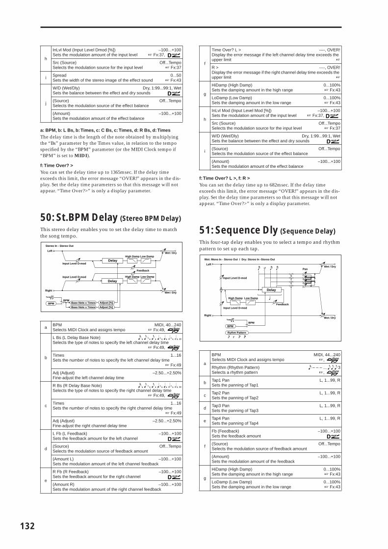
132
a: BPM, b: L Bs, b: Times, c: C Bs, c: Times, d: R Bs, d: TimesThe delay time is the length of the note obtained by multiplying the “Bs” parameter by the Times value, in relation to the tempo specified by the “BPM” parameter (or the MIDI Clock tempo if “BPM” is set to MIDI).
f: Time Over? >You can set the delay time up to 1365msec. If the delay time exceeds this limit, the error message “OVER!” appears in the dis-play. Set the delay time parameters so that this message will not appear. “Time Over?>” is only a display parameter.
50: St.BPM Delay (Stereo BPM Delay)
This stereo delay enables you to set the delay time to match the song tempo.
f: Time Over? L >, f: R >You can set the delay time up to 682msec. If the delay time exceeds this limit, the error message “OVER!” appears in the dis-play. Set the delay time parameters so that this message will not appear. “Time Over?>” is only a display parameter.
51: Sequence Dly (Sequence Delay)
This four-tap delay enables you to select a tempo and rhythm pattern to set up each tap.
h
InLvl Mod (Input Level Dmod [%]) –100...+100Sets the modulation amount of the input level ☞ Fx:37,
Src (Source)Selects the modulation source for the input level
Off...Tempo☞ Fx:37
i Spread 0...50Sets the width of the stereo image of the effect sound ☞ Fx:43
j
W/D (Wet/Dly) Dry, 1:99...99:1, WetSets the balance between the effect and dry sounds
(Source) Off...TempoSelects the modulation source of the effect balance
(Amount)Sets the modulation amount of the effect balance
–100...+100
a BPM MIDI, 40...240Selects MIDI Clock and assigns tempo ☞ Fx:49,
b
L Bs (L Delay Base Note) � � � � � � � � � � � � � � � � � �Selects the type of notes to specify the left channel delay time
☞ Fx:49,
Times 1...16Sets the number of notes to specify the left channel delay time
☞ Fx:49
Adj (Adjust)Fine-adjust the left channel delay time
–2.50...+2.50%
c
R Bs (R Delay Base Note) � � � � � � � � � � � � � � � � � �Selects the type of notes to specify the right channel delay time
☞ Fx:49,
Times 1...16Sets the number of notes to specify the right channel delay time
☞ Fx:49
Adj (Adjust)Fine-adjust the right channel delay time
–2.50...+2.50%
d
L Fb (L Feedback)Sets the feedback amount for the left channel
–100...+100
(Source) Off...TempoSelects the modulation source of feedback amount
(Amount L) –100...+100Sets the modulation amount of the left channel feedback
e
R Fb (R Feedback)Sets the feedback amount for the right channel
–100...+100
(Amount R) –100...+100Sets the modulation amount of the right channel feedback
Left
Right
Feedback
Wet / Dry
Wet / Dry
Stereo In - Stereo Out
Input Level D-mod
Input Level D-mod
High Damp Low Damp
High Damp Low Damp
Tempo
BPMBPM Base Note x Times
Base Note x Times
Adjust [%]
Adjust [%]
Delay
Delay
f
Time Over? L > ----, OVER!Display the error message if the left channel delay time exceeds the upper limit ☞
R > ----, OVER!Display the error message if the right channel delay time exceeds the upper limit ☞
g
HiDamp (High Damp)Sets the damping amount in the high range
0...100%☞ Fx:43
LoDamp (Low Damp)Sets the damping amount in the low range
0...100%☞ Fx:43
h
InLvl Mod (Input Level Mod [%]) –100...+100Sets the modulation amount of the input level ☞ Fx:37,
Src (Source)Selects the modulation source for the input level
Off...Tempo☞ Fx:37
i
W/D (Wet/Dly) Dry, 1:99...99:1, WetSets the balance between the effect and dry sounds
(Source) Off...TempoSelects the modulation source of the effect balance
(Amount)Sets the modulation amount of the effect balance
–100...+100
a
BPMSelects MIDI Clock and assigns tempo
MIDI, 44...240☞,
Rhythm (Rhythm Pattern)Selects a rhythm pattern
� – – – ... � � � 3☞,
b Tap1 PanSets the panning of Tap1
L, 1...99, R
c Tap2 PanSets the panning of Tap2
L, 1...99, R
d Tap3 PanSets the panning of Tap3
L, 1...99, R
e Tap4 PanSets the panning of Tap4
L, 1...99, R
f
Fb (Feedback)Sets the feedback amount
–100...+100
(Source) Off...TempoSelects the modulation source of feedback amount
(Amount)Sets the modulation amount of the feedback
–100...+100
g
HiDamp (High Damp)Sets the damping amount in the high range
0...100%☞ Fx:43
LoDamp (Low Damp)Sets the damping amount in the low range
0...100%☞ Fx:43
Delay
Left
Right
Feedback
Wet / Dry
Wet / Dry
Wet: Mono In - Stereo Out / Dry: Stereo In -Stereo Out
Input Level D-mod
High Damp Low Damp
Input Level D-mod
+
Tempo
BPMBPM
Rythm Pattern
Pan

EFFE
CT
a: BPM, a: RhythmWith the tempo specified by the “BPM” parameter (or the MIDI Clock tempo if “BPM” is set to MIDI), the length of one beat equals the feedback delay time, and the interval between taps becomes equal. Selecting a rhythm will automatically turn the tap outputs on and off. When “BPM” is set to MIDI, the lower limit of the “BPM” is 44.
Reverb
Reverb effectsThese effects simulate the ambience of reverberation in con-cert halls.
52: Rev Hall (Reverb Hall)
This hall-type reverb simulates the reverberation of mid-size concert halls or ensemble halls.
53: Rev Smth. Hall(Reverb Smooth Hall)
This hall-type reverb simulates the reverberation of larger halls and stadiums, and creates a smooth release.
54: Rev Wet Plate (Reverb Wet Plate)
This plate reverb simulates warm (dense) reverberation.
55: Rev Dry Plate (Reverb Dry Plate)
This plate reverb simulates dry (light) reverberation.
c: Pre Delay, d: Pre Delay ThruThe “Pre Delay” sets the delay time to the reverb input, allowing you to control spaciousness.
h
InLvl Mod (Input Level Mod [%]) –100...+100Sets the modulation amount of the input level ☞ Fx:37,
Src (Source)Selects the modulation source for the input level
Off...Tempo☞ Fx:37
i
W/D (Wet/Dly) Dry, 1:99...99:1, WetSets the balance between the effect and dry sounds
(Source) Off...TempoSelects the modulation source of the effect balance
(Amount)Sets the modulation amount of the effect balance
–100...+100
a Reverb TimeSets the reverberation time
0.1...10.0s
b High DampSets the damping amount in the high range
0...100%
c Pre DelaySets the delay time from the dry sound
0...200ms☞
d Pre Delay ThruSets the mix ratio of non-delay sound
0...100%☞
e Pre EQ TrimSets the EQ input level
0...100
f
LoEQ (Pre Low EQ Gain)Sets the gain of Low EQ
–15...+15dB
HiEQ (Pre High EQ Gain)Sets the gain of High EQ
–15...+15dB
g
W/D (Wet/Dly) Dry, 1:99...99:1, WetSets the balance between the effect and dry sounds
(Source) Off...TempoSelects the modulation source of the effect balance
(Amount)Sets the modulation amount of the effect balance
–100...+100
Left
Right
Wet / Dry
Wet / Dry
Wet: Mono In - Stereo Out / Dry: Stereo In - Stereo Out
EQ Trim
+
EQ Trim
LEQ HEQPre Delay Reverb
Pre Delay Thru
133

134
Using the “Pre Delay Thru” parameter, you can mix the dry sound without delay, emphasizing the attack of the sound.
56: Rev Room (Reverb Room)
This room-type reverb emphasizes the early reflections that make the sound tighter. Changing the balance between the early reflections and reverb sound allows you to simulate nuances, such as the type of walls of a room.
57: Rev Brt. Room(Reverb Bright Room)
This room-type reverb emphasizes the early reflections that make the sound brighter. See 56: Reverb Room.
g: ER Level, h: Reverb LevelThese parameters set the early reflection level and reverb level.Changing these parameter values allows you to simulate the type of walls in the room. That is, a larger “ER Level” simulates a hard wall, and a larger “Reverb Level” simulates a soft wall.
a Reverb TimeSets the reverberation time
0.1...3.0sec
b High DampSets the damping amount in the high range
0...100%
c Pre DelaySets the delay time from the dry sound
0...200ms☞ Fx:52
d Pre Delay ThruSets the mix ratio of non-delay sound
0...100%☞ Fx:52
e Pre EQ TrimSets the EQ input level
0...100
f
LoEQ (Pre Low EQ Gain)Sets the gain of Low EQ
–15...+15dB
HiEQ (Pre High EQ Gain)Sets the gain of High EQ
–15...+15dB
g ER LevelSets the level of early reflections
0...100☞
h Reverb LevelSets the reverberation level
0...100☞
i
W/D (Wet/Dly) Dry, 1:99...99:1, WetSets the balance between the effect and dry sounds
(Source) Off...TempoSelects the modulation source of the effect balance
(Amount)Sets the modulation amount of the effect balance
–100...+100
Reverb - Hall / Plate Type
Time
Level
Lo
ud
er
Dry
Reverb
Pre Delay Thru
Pre Delay Reverb Time
Left
Right
Wet / Dry
Wet / Dry
Wet: Mono In - Stereo Out / Dry: Stereo In - Stereo Out
EQ Trim
+
EQ Trim
LEQ HEQ
Pre Delay Reverb Reverb Level
ER Level
ER Level
Pre Delay Thru
ERs
ERs
Reverb - Room Type
Time
Level
Lo
ud
er
ER(Early Reflections)
Dry
Reverb
Pre Delay Thru
Pre Delay Reverb Time

EFFE
CT
Mono → Mono Chain
Effects that combine two mono effects con-nected in series
58: P4EQ–Exciter(Parametric 4-Band EQ – Exciter)
This effect combines a mono-type four-band parametric equalizer and an exciter.
59: P4EQ–Wah(Parametric 4-Band EQ – Wah/Auto Wah)
This effect combines a mono-type four-band parametric equalizer and a wah. You can change the order of the connec-tion.
a [PEQ] TrimSets the parametric EQ input level
0...100
b
B1 (Band1 Cutoff)Sets the center frequency of Band 1
20...1.00kHz
QSets the bandwidth of Band 1
0.5...10.0☞ Fx:06
G (Gain)Sets the gain of Band 1
–18...+18dB
c
B2 (Band2 Cutoff)Sets the center frequency of Band 2
50...5.00kHz
QSets the bandwidth of Band 2
0.5...10.0☞ Fx:06
G (Gain)Sets the gain of Band 2
–18...+18dB
d
B3 (Band3 Cutoff)Sets the center frequency for Band 3
300...10.00kHz
QSets the bandwidth of Band 3
0.5...10.0☞ Fx:06
G (Gain)Sets the gain of Band 3
–18...+18dB
e
B4 (Band4 Cutoff)Sets the center frequency for Band 4
500...20.00kHz
QSets the bandwidth of Band 4
0.5...10.0☞ Fx:06
G (Gain)Sets the gain of Band 4
–18...+18dB
f [XCT] Blend (Exciter Blend)Sets the intensity (depth) of the Exciter effect
–100...+100☞ Fx:11
g Emphatic PointSets the frequency range to be emphasized
0...70☞ Fx:11
h
W/D (Wet/Dly) Dry, 1:99...99:1, WetSets the balance between the effect and dry sounds
(Source) Off...TempoSelects the modulation source of the effect balance
(Amount)Sets the modulation amount of the effect balance
–100...+100
Left
Right
Wet / Dry
Wet / Dry
Wet: Mono In - Mono Out / Dry: Stereo In - Stereo Out
Trim+ Exciter
Parametric 4Band EQ Exciter
a [PEQ] TrimSets the parametric EQ input level
0...100
b
B1 (Band1 Cutoff)Sets the center frequency of Band 1
20...1.00kHz
QSets the bandwidth of Band 1
0.5...10.0☞ Fx:06
G (Gain)Sets the gain of Band 1
–18...+18dB
c
B2 (Band2 Cutoff)Sets the center frequency of Band 2
50...5.00kHz
QSets the bandwidth of Band 2
0.5...10.0☞ Fx:06
G (Gain)Sets the gain of Band 2
–18...+18dB
d
B3 (Band3 Cutoff)Sets the center frequency for Band 3
300...10.00kHz
QSets the bandwidth of Band 3
0.5...10.0☞ Fx:06
G (Gain)Sets the gain of Band 3
–18...+18dB
e
B4 (Band4 Cutoff)Sets the center frequency for Band 4
500...20.00kHz
QSets the bandwidth of Band 4
0.5...10.0☞ Fx:06
G (Gain)Sets the gain of Band 4
–18...+18dB
f
[WAH] FreqBtm (Frequency Bottom)Sets the lower limit of the wah center frequency
0...100☞ Fx:09
Top (Frequency Top)Sets the upper limit of the wah center frequency
0...100☞ Fx:09
g
Swp Mode (Sweep Mode) Auto, Dmod, LFOSelects the control from auto-wah, modulation source, and LFO
☞ Fx:09,
Src (Source) Off...TempoSelects the modulation source for the wah when Sweep Mode=D-mod
h
lfoF (LFO Frequency)Sets the LFO speed
0.02...20.00Hz
Res (Resonance)Sets the resonance amount
0...100
LPF (Low Pass Filter)Switches the wah low pass filter on and off
Of, On
i [Routing] PEQ → WAH, WAH → PEQChanges the order of the parametric equalizer and wah connection
j
W/D (Wet/Dly) Dry, 1:99...99:1, WetSets the balance between the effect and dry sounds
(Source) Off...TempoSelects the modulation source of the effect balance
(Amount)Sets the modulation amount of the effect balance
–100...+100
Left
Right
Wet / Dry
Wet / Dry
Wet: Mono In - Mono Out / Dry: Stereo In - Stereo Out
Trim+
Parametric 4Band EQRouting
Wah/Auto Wah
Wah
D-mod
EnvelopeSweep Mode
D-modAuto
LFOLFO
135

136
60: P4EQ–Cho/Fl(Parametric 4-Band EQ – Chorus/Flanger)
This effect combines a mono-type four-band parametric equalizer and a chorus/flanger.
h: OutWhen Wet Inv is selected, the right channel phase of the chorus/flanger effect sound is inverted. This creates pseudo-stereo effects and adds spread.However, if a mono-input type effect is connected after this effect, the left and right sounds may cancel each other, eliminating the chorus/flanger effects.
61: P4EQ–Phaser (Parametric 4-Band EQ – Phaser)
This effect combines a mono-type four-band parametric equalizer and a phaser.
a [PEQ] TrimSets the parametric EQ input level
0...100
b
B1 (Band1 Cutoff)Sets the center frequency of Band 1
20...1.00kHz
QSets the bandwidth of Band 1
0.5...10.0☞ Fx:06
G (Gain)Sets the gain of Band 1
–18...+18dB
c
B2 (Band2 Cutoff)Sets the center frequency of Band 2
50...5.00kHz
QSets the bandwidth of Band 2
0.5...10.0☞ Fx:06
G (Gain)Sets the gain of Band 2
–18...+18dB
d
B3 (Band3 Cutoff)Sets the center frequency for Band 3
300...10.00kHz
QSets the bandwidth of Band 3
0.5...10.0☞ Fx:06
G (Gain)Sets the gain of Band 3
–18...+18dB
e
B4 (Band4 Cutoff)Sets the center frequency for Band 4
500...20.00kHz
QSets the bandwidth of Band 4
0.5...10.0☞ Fx:06
G (Gain)Sets the gain of Band 4
–18...+18dB
f
[CH/FL] LFO (LFO Waveform)Selects the LFO waveform of the chorus/flanger
Tri, Sine
F (LFO Frequency)Sets the LFO speed
0.02...20.00Hz
g
Dly (Delay Time)Sets the delay time
0.0...50.0ms
Dep (Depth)Sets the depth of LFO modulation
0...100
Fb (Feedback)Sets the feedback amount
–100...+100☞ Fx:20
h
C/F W/D (Cho/Flng Wet/Dry) –Wet...–2:98, Dry, 2:98...WetSets the effect balance of the chorus/flanger ☞ Fx:10, 20
Out (Output Mode) Normal, Wet InvSelects the output mode for the chorus/flanger ☞
i
W/D (Wet/Dly) Dry, 1:99...99:1, WetSets the balance between the effect and dry sounds
(Source) Off...TempoSelects the modulation source of the effect balance
(Amount)Sets the modulation amount of the effect balance
–100...+100
Left
Right
Wet / Dry
Wet: Mono In - Stereo Out / Dry: Stereo In - Stereo Out
Trim
+
Parametric 4Band EQ Chorus/Flanger
Wet / Dry
Chorus/Flanger
Feedback
LFO: Tri / Sine
Cho/Flng Wet / Dry
Normal
Wet InvertOutput Mode
–+
a [PEQ] TrimSets the parametric EQ input level
0...100
b
B1 (Band1 Cutoff)Sets the center frequency of Band 1
20...1.00kHz
QSets the bandwidth of Band 1
0.5...10.0☞ Fx:06
G (Gain)Sets the gain of Band 1
–18...+18dB
c
B2 (Band2 Cutoff)Sets the center frequency of Band 2
50...5.00kHz
QSets the bandwidth of Band 2
0.5...10.0☞ Fx:06
G (Gain)Sets the gain of Band 2
–18...+18dB
d
B3 (Band3 Cutoff)Sets the center frequency for Band 3
300...10.00kHz
QSets the bandwidth of Band 3
0.5...10.0☞ Fx:06
G (Gain)Sets the gain of Band 3
–18...+18dB
e
B4 (Band4 Cutoff)Sets the center frequency for Band 4
500...20.00kHz
QSets the bandwidth of Band 4
0.5...10.0☞ Fx:06
G (Gain)Sets the gain of Band 4
–18...+18dB
f
[PHS] LFO (LFO Waveform)Selects the LFO waveform of the phaser
Tri, Sine
F (LFO Frequency)Sets the LFO speed
0.02...20.00Hz
g
Manu (Manual)Sets the frequency to which the effect is applied
0...100
Dep (Depth)Sets the depth of LFO modulation
0...100
Res (Resonance)Sets the resonance amount
–100...+100☞ Fx:23
h
Phs W/D (Phaser Wet/Dry) –Wet...–2:98, Dry, 2:98...WetSets the phaser effect balance ☞ Fx:10, 23
Output Mode Normal, Wet InvSelects the phaser output mode ☞ Fx:60
i
W/D (Wet/Dly) Dry, 1:99...99:1, WetSets the balance between the effect and dry sounds
(Source) Off...TempoSelects the modulation source of the effect balance
(Amount)Sets the modulation amount of the effect balance
–100...+100
Left
Right
Wet / Dry
Wet / Dry
Wet: Mono In - Stereo Out / Dry: Stereo In - Stereo Out
Trim+
Parametric 4Band EQ Phaser
Phaser
Resonance
LFO: Tri / Sine
Phaser Wet / Dry
Normal
Wet Invert
Output Mode–+

EFFE
CT
62: P4EQ–M.Dly (Parametric 4-Band EQ – Multitap Delay)
This effect combines a mono-type four-band parametric equalizer and a multitap delay.
63: Comp–Wah(Compressor – Wah/Auto Wah)
This effect combines a mono-type compressor and a wah. You can change the order of the connection.
a [PEQ] TrimSets the parametric EQ input level
0...100
b
B1 (Band1 Cutoff)Sets the center frequency of Band 1
20...1.00kHz
QSets the bandwidth of Band 1
0.5...10.0☞ Fx:06
G (Gain)Sets the gain of Band 1
–18...+18dB
c
B2 (Band2 Cutoff)Sets the center frequency of Band 2
50...5.00kHz
QSets the bandwidth of Band 2
0.5...10.0☞ Fx:06
G (Gain)Sets the gain of Band 2
–18...+18dB
d
B3 (Band3 Cutoff)Sets the center frequency for Band 3
300...10.00kHz
QSets the bandwidth of Band 3
0.5...10.0☞ Fx:06
G (Gain)Sets the gain of Band 3
–18...+18dB
e
B4 (Band4 Cutoff)Sets the center frequency for Band 4
500...20.00kHz
QSets the bandwidth of Band 4
0.5...10.0☞ Fx:06
G (Gain)Sets the gain of Band 4
–18...+18dB
f
[DLY] T1 (Tap1 Delay)Sets the Tap1 delay time
0...680ms
T2 (Tap2 Delay)Sets the Tap2 delay time
0...680ms
g
T1 Level (Tap1 Level)Sets the Tap1 output level
0...100☞ Fx:45
T2 Fb (Tap2 Feedback)Sets the Tap2 feedback amount
–100...+100
h
Dly W/D (Delay Wet/Dry) Dry, 2:98...98:2, WetSets the multitap delay effect balance
HiDamp (High Damp)Sets the damping amount in the high range
0...100%☞ Fx:43
i
W/D (Wet/Dly) Dry, 1:99...99:1, WetSets the balance between the effect and dry sounds
(Source) Off...TempoSelects the modulation source of the effect balance
(Amount)Sets the modulation amount of the effect balance
–100...+100
Left
Right
Wet / Dry
Wet / Dry
Wet: Mono In - Mono Out / Dry: Stereo In - Stereo Out
Trim+
Parametric 4Band EQ Multitap Delay
Feedback
High Damp
Delay(2)
(1)Mt.Dly Wet / Dry
a [CMP] SensitivitySets the sensitivity
1...100☞ Fx:02
b
AttackSets the attack level
1...100☞ Fx:02
Level (Output Level)Sets the compressor output level
0...100☞ Fx:02
c Pre EQ TrimSets the EQ input level
0...100
d
LoEQ (Pre Low EQ Gain)Sets the gain of Low EQ
–15...+15dB
HiEQ (Pre High EQ Gain)Sets the gain of High EQ
–15...+15dB
e
[WAH] FreqBtm (Frequency Bottom)Sets the lower limit of the wah center frequency
0...100☞ Fx:09
Top (Frequency Top)Sets the upper limit of the wah center frequency
0...100☞ Fx:09
f
Swp Mode (Sweep Mode) Auto, Dmod, LFOSelects the control from auto-wah, modulation source, and LFO
☞ Fx:09,
Src (Source) Off...TempoSelects the modulation source for the wah when Swp Mode=Dmod
g
lfoF (LFO Frequency)Sets the LFO speed
0.02...20.00Hz
Res (Resonance)Sets the resonance amount
0...100
LPF (Low Pass Filter)Switches the wah low pass filter on and off
Of, On
h [Routing] CMP → WAH, WAH → CMPSwitches the order of the compressor and wah connection
i
W/D (Wet/Dly) Dry, 1:99...99:1, WetSets the balance between the effect and dry sounds
(Source) Off...TempoSelects the modulation source of the effect balance
(Amount)Sets the modulation amount of the effect balance
–100...+100
Left
Right
Wet / Dry
Wet / Dry
Wet: Mono In - Mono Out / Dry: Stereo In - Stereo Out
+
CompressorRouting
Wah/Auto Wah
Wah
D-mod
EnvelopeSweep Mode
D-modAuto
LFO
LFO
LEQ HEQEQ Trim
CompOutput Level
Envelope - Control
137

138
64: Comp–AmpSim(Compressor – Amp Simulation)
This effect combines a mono-type compressor and an amp simulation. You can change the order of the effect connection.
65: Comp–OD/HG(Compressor – Overdrive/Hi.Gain)
This effect combines a mono-type compressor and an over-drive/high-gain distortion. You can change the order of the effect connection.
66: Comp–P4EQ(Compressor – Parametric 4-Band EQ)
This effect combines a mono-type compressor and a four-band parametric equalizer. You can change the order of the effect connection.
a [CMP] SensitivitySets the sensitivity
1...100☞ Fx:02
b
AttackSets the attack level
1...100☞ Fx:02
Level (Output Level)Sets the compressor output level
0...100☞ Fx:02
c Pre EQ TrimSets the EQ input level
0...100
d
LoEQ (Pre Low EQ Gain)Sets the gain of Low EQ
–15...+15dB
HiEQ (Pre High EQ Gain)Sets the gain of High EQ
–15...+15dB
e [AMP] Amplifier TypeSelects the type of guitar amplifier
SS, EL84, 6L6
f[Routing] CMP → AMP, AMP → CMPSwitches the order of the compressor and amp simulation connec-tion
g
W/D (Wet/Dly) Dry, 1:99...99:1, WetSets the balance between the effect and dry sounds
(Source) Off...TempoSelects the modulation source of the effect balance
(Amount)Sets the modulation amount of the effect balance
–100...+100
a [CMP] SensitivitySets the sensitivity
1...100☞ Fx:02
b
AttackSets the attack level
1...100☞ Fx:02
Level (Output Level)Sets the compressor output level
0...100☞ Fx:02
c
[OD] Mode (Drive Mode) OverD, Hi-GainSwitches between overdrive and high-gain distortion
DriveSets the degree of distortion
1...100☞ Fx:06
Left
Right
Wet / Dry
Wet / Dry
Wet: Mono In - Mono Out / Dry: Stereo In - Stereo Out
+
CompressorRouting
Amp Simulation
Amp Simulation FilterLEQ HEQEQ Trim
Output Level
Envelope - Control
Comp
Left
Right
Wet / Dry
Wet / Dry
Wet: Mono In - Mono Out / Dry: Stereo In - Stereo Out
+
RoutingOverdrive / Hi-Gain
3 Band PEQ
Output Level
Mode: Overdrive / Hi-GainDrive
Driver
Compressor
Output Level
Envelope - Control
Comp
d
Level (Output Level) 0...50Sets the overdrive output level ☞ Fx:06,
(Source) Off...TempoSelects the modulation source for the overdrive output level
(Amount) –50...+50Sets the modulation amount of the overdrive output level
e
Lo (Low Cutoff) 20...1.00kHzSets the center frequency for Low EQ (shelving type)
G (Gain)Sets the gain of Low EQ
–18...+18dB
f
M1 (Mid1 Cutoff) 300...10.00kHzSets the center frequency for Mid/High EQ 1 (peaking type)
QSets the band width of Mid/High EQ 1
0.5...10.0☞ Fx:06
G (Gain)Sets the gain of Mid/High EQ 1
–18...+18dB
g
M2 (Mid2 Cutoff) 500...20.00kHzSets the center frequency for Mid/High EQ 2 (peaking type)
QSets the band width of Mid/High EQ 2
0.5...10.0☞ Fx:06
G (Gain)Sets the gain of Mid/High EQ 2
–18...+18dB
h [Routing] CMP → OD, OD → CMPSwitches the order of the compressor and overdrive connection
i
W/D (Wet/Dly) Dry, 1:99...99:1, WetSets the balance between the effect and dry sounds
(Source) Off...TempoSelects the modulation source of the effect balance
(Amount)Sets the modulation amount of the effect balance
–100...+100
a [CMP] SensitivitySets the sensitivity
1...100☞ Fx:02
b
AttackSets the attack level
1...100☞ Fx:02
Level (Output Level)Sets the compressor output level
0...100☞ Fx:02
c [PEQ] TrimSets the parametric EQ input level
0...100
d [Routing] CMP → PEQ, PEQ → CMPSwitches the order of the compressor and parametric EQ connection
e
B1 (Band1 Cutoff)Sets the center frequency of Band 1
20...1.00kHz
QSets the bandwidth of Band 1
0.5...10.0☞ Fx:06
G (Gain)Sets the gain of Band 1
–18...+18dB
f
B2 (Band2 Cutoff)Sets the center frequency of Band 2
50...5.00kHz
QSets the bandwidth of Band 2
0.5...10.0☞ Fx:06
G (Gain)Sets the gain of Band 2
–18...+18dB
Left
Right
Wet / Dry
Wet / Dry
Wet: Mono In - Mono Out / Dry: Stereo In - Stereo Out
+
RoutingCompressor
Trim
Parametric 4Band EQ
Output Level
Envelope - Control
Comp
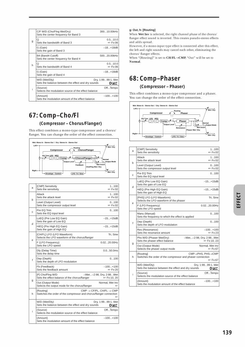
EFFE
CT
67: Comp–Cho/Fl(Compressor – Chorus/Flanger)
This effect combines a mono-type compressor and a chorus/flanger. You can change the order of the effect connection.
g: Out, h: [Routing]When Wet Inv is selected, the right channel phase of the chorus/flanger effect sound is inverted. This creates pseudo-stereo effects and adds spread.However, if a mono-input type effect is connected after this effect, the left and right sounds may cancel each other, eliminating the chorus/flanger effects.When “[Routing]” is set to CH/FL→CMP, “Out” will be set to Normal.
68: Comp–Phaser(Compressor – Phaser)
This effect combines a mono-type compressor and a phaser. You can change the order of the effect connection.
g
C/F W/D (Cho/Flng Wet/Dry)Sets the center frequency for Band 3
300...10.00kHz
QSets the bandwidth of Band 3
0.5...10.0☞ Fx:06
G (Gain)Sets the gain of Band 3
–18...+18dB
h
B4 (Band4 Cutoff)Sets the center frequency for Band 4
500...20.00kHz
QSets the bandwidth of Band 4
0.5...10.0☞ Fx:06
G (Gain)Sets the gain of Band 4
–18...+18dB
i
W/D (Wet/Dly) Dry, 1:99...99:1, WetSets the balance between the effect and dry sounds
(Source) Off...TempoSelects the modulation source of the effect balance
(Amount)Sets the modulation amount of the effect balance
–100...+100
a [CMP] SensitivitySets the sensitivity
1...100☞ Fx:02
b
AttackSets the attack level
1...100☞ Fx:02
Level (Output Level)Sets the compressor output level
0...100☞ Fx:02
c Pre EQ TrimSets the EQ input level
0...100
d
LoEQ (Pre Low EQ Gain)Sets the gain of Low EQ
–15...+15dB
HiEQ (Pre High EQ Gain)Sets the gain of High EQ
–15...+15dB
e
[CH/FL] LFO (LFO Waveform)Selects the LFO waveform of the chorus/flanger
Tri, Sine
F (LFO Frequency)Sets the LFO speed
0.02...20.00Hz
f
Dly (Delay Time)Sets the delay time
0.0...50.0ms
Dep (Depth)Sets the depth of LFO modulation
0...100
Fb (Feedback)Sets the feedback amount
–100...+100☞ Fx:20
g
[F] Cho/Flng W/D –Wet...–2:98, Dry, 2:98...WetSets the effect balance of the chorus/flanger ☞ Fx:10, 20
Out (Output Mode) Normal, Wet InvSelects the output mode for the chorus/flanger ☞
h[Routing] CMP → CF/FL, CH/FL → CMPSwitches the order of the compressor and chorus/flanger connection
☞
i
W/D (Wet/Dly) Dry, 1:99...99:1, WetSets the balance between the effect and dry sounds
(Source) Off...TempoSelects the modulation source of the effect balance
(Amount)Sets the modulation amount of the effect balance
–100...+100
Left
Right
Wet / Dry
Wet / Dry
Wet: Mono In - Stereo Out / Dry: Stereo In - Stereo Out
+
RoutingCompressor Chorus/Flanger
Chorus/Flanger
Feedback
LFO: Tri / Sine
Cho/Flng Wet / Dry
Normal
Wet Invert
Output Mode–+
LEQ HEQEQ TrimComp
Output Level
Envelope - Control
a [CMP] SensitivitySets the sensitivity
1...100☞ Fx:02
b
AttackSets the attack level
1...100☞ Fx:02
Level (Output Level)Sets the compressor output level
0...100☞ Fx:02
c Pre EQ TrimSets the EQ input level
0...100
d
LoEQ (Pre Low EQ Gain)Sets the gain of Low EQ
–15...+15dB
HiEQ (Pre High EQ Gain)Sets the gain of High EQ
–15...+15dB
e
[PHS] LFO (LFO Waveform)Selects the LFO waveform of the phaser
Tri, Sine
F (LFO Frequency)Sets the LFO speed
0.02...20.00Hz
f
Manu (Manual)Sets the frequency to which the effect is applied
0...100
Dep (Depth)Sets the depth of LFO modulation
0...100
Res (Resonance)Sets the resonance amount
–100...+100☞ Fx:23
g
Phs W/D (Phaser Wet/Dry) –Wet...–2:98, Dry, 2:98...WetSets the phaser effect balance ☞ Fx:10, 23
Out (Output Mode) Normal, Wet InvSelects the phaser output mode ☞ Fx:67
h[Routing] CMP→PHS, PHS→CMPSwitches the order of the compressor and phaser connection
☞ Fx:67
i
W/D (Wet/Dly) Dry, 1:99...99:1, WetSets the balance between the effect and dry sounds
(Source) Off...TempoSelects the modulation source of the effect balance
(Amount)Sets the modulation amount of the effect balance
–100...+100
Left
Right
Wet / Dry
Wet / Dry
Wet: Mono In - Stereo Out / Dry: Stereo In - Stereo Out
+
RoutingCompressor
LEQ HEQEQ Trim
Comp
Output Level
Envelope - Control
Phaser
Phaser
Resonance
LFO: Tri / Sine
Phaser Wet / Dry
Normal
Wet InvertOutput Mode
–+
139

140
69: Comp–M.Dly(Compressor – Multitap Delay)
This effect combines a mono-type compressor and a multitap delay. You can change the order of the effect connection.
70: Limit–P4EQ(Limiter – Parametric 4-Band EQ)
This effect combines a mono-type limiter and a four-band parametric equalizer. You can change the order of the effect connection.
a [CMP] SensitivitySets the sensitivity
1...100☞ Fx:02
b
AttackSets the attack level
1...100☞ Fx:02
Level (Output Level)Sets the compressor output level
0...100☞ Fx:02
c Pre EQ TrimSets the EQ input level
0...100
d
LoEQ (Pre Low EQ Gain)Sets the gain of Low EQ
–15...+15dB
HiEQ (Pre High EQ Gain)Sets the gain of High EQ
–15...+15dB
e
[DLY] T1 (Tap1 Delay)Sets the Tap1 delay time
0...680msec
T2 (Tap2 Delay)Sets the Tap2 delay time
0...680msec
f
T1 Level (Tap1 Level)Sets the Tap1 output level
0...100☞ Fx:45
T2 (Tap2 Delay)Sets the Tap2 feedback amount
–100...+100
g
Dly W/D (Delay Wet/Dry) Dry, 1:99...99:1, WetSets the multitap delay effect balance
HiDamp (High Damp)Sets the damping amount in the high range
0...100%☞ Fx:43
h [Routing] CMP→DLY, DLY→CMPSwitches the order of the compressor and multitap delay connection
i
W/D (Wet/Dly) Dry, 1:99...99:1, WetSets the balance between the effect and dry sounds
(Source) Off...TempoSelects the modulation source of the effect balance
(Amount)Sets the modulation amount of the effect balance
–100...+100
Left
Right
Wet / Dry
Wet / Dry
Wet: Mono In - Mono Out / Dry: Stereo In - Stereo Out
+
RoutingCompressor
LEQ HEQEQ Trim
Output Level
Envelope - Control
Multitap Delay
Feedback
High Damp
Delay(2)
(1)Mt.Dly Wet / Dry
Comp
a [LMT] Ratio 1.0:1...50.0:1, Inf:1Sets the signal compression ratio ☞ Fx:03
b
Threshld (Threshold) –40...0dBSets the level above which the compressor is applied ☞ Fx:03
G.Adj (Gain Adjust)Sets the limiter output gain
–Inf, –38...+24dB☞ Fx:03
c
AttackSets the attack time
1...100☞ Fx:03
ReleaseSets the release time
1...100☞ Fx:03
d [PEQ] TrimSets the parametric EQ input level
0...100
e [Routing] LMT→PEQ, PEQ→LMTSwitches the order of the limiter and parametric EQ connection
f
B1 (Band1 Cutoff)Sets the center frequency of Band 1
20...1.00kHz
QSets the bandwidth of Band 1
0.5...10.0☞ Fx:06
G (Gain)Sets the gain of Band 1
–18...+18dB
g
B2 (Band2 Cutoff)Sets the center frequency of Band 2
50...5.00kHz
QSets the bandwidth of Band 2
0.5...10.0☞ Fx:06
G (Gain)Sets the gain of Band 2
–18...+18dB
h
B3 (Band3 Cutoff)Sets the center frequency for Band 3
300...10.00kHz
QSets the bandwidth of Band 3
0.5...10.0☞ Fx:06
G (Gain)Sets the gain of Band 3
–18...+18dB
i
B4 (Band4 Cutoff)Sets the center frequency for Band 4
500...20.00kHz
QSets the bandwidth of Band 4
0.5...10.0☞ Fx:06
G (Gain)Sets the gain of Band 4
–18...+18dB
j
W/D (Wet/Dly) Dry, 1:99...99:1, WetSets the balance between the effect and dry sounds
(Source) Off...TempoSelects the modulation source of the effect balance
(Amount)Sets the modulation amount of the effect balance
–100...+100
Left
Right
Wet / Dry
Wet / Dry
Wet: Mono In - Mono Out / Dry: Stereo In - Stereo Out
+
RoutingLimiter
Trim
Parametric 4Band EQ
Limiter
Gain Adjust
Envelope - Control

EFFE
CT
71: Limit–Cho/Fl(Limiter – Chorus/Flanger)
This effect combines a mono-type limiter and a chorus/flanger. You can change the order of the effect connection.
72: Limit–Phaser(Limiter – Phaser)
This effect combines a mono-type limiter and a phaser. You can change the order of the effect connection.
a [LMT] Ratio 1.0:1...50.0:1, Inf:1Sets the signal compression ratio ☞ Fx:03
b
Threshld (Threshold) –40...0dBSets the level above which the compressor is applied ☞ Fx:03
G.Adj (Gain Adjust)Sets the limiter output gain
–Inf, –38...+24dB☞ Fx:03
c
AttackSets the attack time
1...100☞ Fx:03
ReleaseSets the release time
1...100☞ Fx:03
d
[CH/FL] LFO (LFO Waveform)Selects the LFO waveform of the chorus/flanger
Tri, Sine
F (LFO Frequency)Sets the LFO speed
0.02...20.00Hz
e
Dly (Delay Time)Sets the delay time
0.0...50.0ms
Dep (Depth)Sets the depth of LFO modulation
0...100
FeedbackSets the feedback amount
–100...+100☞ Fx:20
f [F] EQ TrimSets the EQ input level
0...100
g
[F] Pre LEQ Gain [dB]Sets the gain of Low EQ
–15...+15dB
Pre HEQ Gain [dB]Sets the gain of High EQ
–15...+15dB
h
[F] Cho/Flng W/D –Wet...–2:98, Dry, 2:98...WetSets the effect balance of the chorus/flanger ☞ Fx:10, 20
Output Mode Normal, Wet InvSelects the output mode for the chorus/flanger ☞ Fx:67
iRouting LMT→CH/FL, CH/FL→LMTSwitches the order of the limiter and chorus/flanger connection
☞ Fx:67
j
W/D (Wet/Dly) Dry, 1:99...99:1, WetSets the balance between the effect and dry sounds
(Source) Off...TempoSelects the modulation source of the effect balance
(Amount)Sets the modulation amount of the effect balance
–100...+100
Left
Right
Wet / Dry
Wet / Dry
Wet: Mono In - Stereo Out / Dry: Stereo In - Stereo Out
+
RoutingChorus/Flanger
FeedbackCho/Flng Wet / Dry
Normal
Wet InvertOutput Mode
–+
Limiter
Limiter
Gain Adjust
Envelope - Control
LEQ HEQEQ TrimChorus/Flanger
LFO: Tri / Sine
a [LMT] Ratio 1.0:1...50.0:1, Inf:1Sets the signal compression ratio ☞ Fx:03
b
Threshld (Threshold) –40...0dBSets the level above which the compressor is applied ☞ Fx:03
G.Adj (Gain Adjust)Sets the limiter output gain
–Inf, –38...+24dB☞ Fx:03
c
AttackSets the attack time
1...100☞ Fx:03
ReleaseSets the release time
1...100☞ Fx:03
d
[PHS] LFO (LFO Waveform)Selects the LFO waveform of the phaser
Tri, Sine
F (LFO Frequency)Sets the LFO speed
0.02...20.00Hz
e
Manu (Manual)Sets the frequency to which the effect is applied
0...100
Dep (Depth)Sets the depth of LFO modulation
0...100
ResonanceSets the resonance amount
–100...+100☞ Fx:23
f
[P] Phaser W/D –Wet...–2:98, Dry, 2:98...WetSets the phaser effect balance ☞ Fx:10, 23
Output Mode Normal, Wet InvSelects the phaser output mode ☞ Fx:67
g Routing LMT→PHS, PHS→LMTSwitches the order of the limiter and phaser connection ☞ Fx:67
h
W/D (Wet/Dly) Dry, 1:99...99:1, WetSets the balance between the effect and dry sounds
(Source) Off...TempoSelects the modulation source of the effect balance
(Amount)Sets the modulation amount of the effect balance
–100...+100
Left
Right
Wet / Dry
Wet / Dry
Wet: Mono In - Stereo Out / Dry: Stereo In - Stereo Out
+
RoutingLimiter
LimiterGain Adjust
Envelope - Control
Phaser
Phaser
Resonance
LFO: Tri / Sine
Phaser Wet / Dry
Normal
Wet InvertOutput Mode
–+
141

142
73: Limit–M.Dly (Limiter – Multitap Delay)
This effect combines a mono-type limiter and a multitap delay. You can change the order of the effect connection.
74: Exct–Comp (Exciter – Compressor)
This effect combines a mono-type exciter and a compressor. You can change the order of the effect connection.
75: Exct–Limiter (Exciter – Limiter)
This effect combines a mono-type exciter and a limiter. You can change the order of the effect connection.
a [LMT] Ratio 1.0:1...50.0:1, Inf:1Sets the signal compression ratio ☞ Fx:03
b
Threshld (Threshold) –40...0dBSets the level above which the compressor is applied ☞ Fx:03
G.Adj (Gain Adjust)Sets the limiter output gain
–Inf, –38...+24dB☞ Fx:03
c
AttackSets the attack time
1...100☞ Fx:03
ReleaseSets the release time
1...100☞ Fx:03
d
[DLY] T1 (Tap1 Delay)Sets the Tap1 delay time
0...680ms
T2 (Tap2 Delay)Sets the Tap2 delay time
0...680ms
e
T1 Level (Tap1 Level)Sets the Tap1 output level
0...100☞ Fx:45
T2 Fb (Tap2 Feedback)Sets the Tap2 feedback amount
–100...+100
f
Dly W/D (Delay Wet/Dry) Dry, 1:99...99:1, WetSets the multitap delay effect balance
HiDamp (High Damp)Sets the damping amount in the high range
0...100%☞ Fx:43
g [Routing] LMT→DLY, DLY→LMTSwitches the order of the limiter and multitap delay connection
h
W/D (Wet/Dly) Dry, 1:99...99:1, WetSets the balance between the effect and dry sounds
(Source) Off...TempoSelects the modulation source of the effect balance
(Amount)Sets the modulation amount of the effect balance
–100...+100
a [XCT] Blend (Exciter Blend)Sets the intensity (depth) of the Exciter effect
–100...+100☞ Fx:11
b Emphatic PointSets the frequency range to be emphasized
0...70☞ Fx:11
c Pre EQ TrimSets the EQ input level
0...100
Left
Right
Wet / Dry
Wet / Dry
Wet: Mono In - Mono Out / Dry: Stereo In - Stereo Out
+
RoutingMultitap Delay
Feedback
High Damp
Delay(2)
(1)Mt.Dly Wet / Dry
Limiter
LimiterGain Adjust
Envelope - Control
Left
Right
Wet / Dry
Wet / Dry
Wet: Mono In - Mono Out / Dry: Stereo In - Stereo Out
+
RoutingCompressor
LEQ HEQEQ Trim
CompOutput Level
Envelope - Control
Exciter
Exciter
d
LoEQ (Pre Low EQ Gain)Sets the gain of Low EQ
–15...+15dB
HiEQ (Pre High EQ Gain)Sets the gain of High EQ
–15...+15dB
e [CMP] SensitivitySets the sensitivity
1...100☞ Fx:02
f
AttackSets the attack level
1...100☞ Fx:02
Level (Output Level)Sets the compressor output level
0...100☞ Fx:02
g [Routing] XCT→CMP, CMP→XCTSwitches the order of the exciter and compressor connection
h
W/D (Wet/Dly) Dry, 1:99...99:1, WetSets the balance between the effect and dry sounds
(Source) Off...TempoSelects the modulation source of the effect balance
(Amount)Sets the modulation amount of the effect balance
–100...+100
a [XCT] Blend (Exciter Blend)Sets the intensity (depth) of the Exciter effect
–100...+100☞ Fx:11
b Emphatic PointSets the frequency range to be emphasized
0...70☞ Fx:11
c Pre EQ TrimSets the EQ input level
0...100
d
LoEQ (Pre Low EQ Gain)Sets the gain of Low EQ
–15...+15dB
HiEQ (Pre High EQ Gain)Sets the gain of High EQ
–15...+15dB
e [LMT] Ratio 1.0:1...50.0:1, Inf:1Sets the signal compression ratio ☞ Fx:03
f
Threshld (Threshold) –40...0dBSets the level above which the compressor is applied ☞ Fx:03
G.Adj (Gain Adjust)Sets the limiter output gain
–Inf, –38...+24dB☞ Fx:03
g
AttackSets the attack time
1...100☞ Fx:03
ReleaseSets the release time
1...100☞ Fx:03
h [Routing] XCT→LMT, LMT→XCTSwitches the order of the exciter and limiter connection
i
W/D (Wet/Dly) Dry, 1:99...99:1, WetSets the balance between the effect and dry sounds
(Source) Off...TempoSelects the modulation source of the effect balance
(Amount)Sets the modulation amount of the effect balance
–100...+100
Left
Right
Wet / Dry
Wet / Dry
Wet: Mono In - Mono Out / Dry: Stereo In - Stereo Out
+
Routing
LEQ HEQEQ Trim
Exciter
Exciter Limiter
Limiter
Gain Adjust
Envelope - Control

EFFE
CT
76: Exct–Cho/Fl(Exciter – Chorus/Flanger)
This effect combines a mono-type limiter and a chorus/flanger.
77: Exct–Phaser (Exciter – Phaser)
This effect combines a mono-type limiter and a phaser.
78: Exct–M.Dly(Exciter – Multitap Delay)
This effect combines a mono-type exciter and a multitap delay.
a [XCT] Blend (Exciter Blend)Sets the intensity (depth) of the Exciter effect
–100...+100☞ Fx:11
b Emphatic PointSets the frequency range to be emphasized
0...70☞ Fx:11
c Pre EQ TrimSets the EQ input level
0...100
d
LoEQ (Pre Low EQ Gain)Sets the gain of Low EQ
–15...+15dB
HiEQ (Pre High EQ Gain)Sets the gain of High EQ
–15...+15dB
e
[CH/FL] LFO (LFO Waveform)Selects the LFO waveform of the chorus/flanger
Tri, Sine
F (LFO Frequency)Sets the LFO speed
0.02...20.00Hz
f
Dly (Delay Time)Sets the delay time
0.0...50.0ms
Dep (Depth)Sets the depth of LFO modulation
0...100
Fb (Feedback)Sets the feedback amount
–100...+100☞ Fx:20
g
C/F W/D (Cho/Flng Wet/Dry) –Wet...–2:98, Dry, 2:98...WetSets the effect balance of the chorus/flanger ☞ Fx:10, 20
Out (Output Mode) Normal, Wet InvSelects the output mode for the chorus/flanger ☞ Fx:60
h
W/D (Wet/Dly) Dry, 1:99...99:1, WetSets the balance between the effect and dry sounds
(Source) Off...TempoSelects the modulation source of the effect balance
(Amount)Sets the modulation amount of the effect balance
–100...+100
a [XCT] Blend (Exciter Blend)Sets the intensity (depth) of the Exciter effect
–100...+100☞ Fx:11
b Emphatic PointSets the frequency range to be emphasized
0...70☞ Fx:11
c Pre EQ TrimSets the EQ input level
0...100
Left
Right
Wet / Dry
Wet / Dry
Wet: Mono In - Stereo Out / Dry: Stereo In - Stereo Out
+
Chorus/Flanger
Chorus/Flanger
Feedback
LFO: Tri / Sine
Cho/Flng Wet / Dry
Normal
Wet InvertOutput Mode
–+
LEQ HEQEQ Trim
Exciter
Exciter
Left
Right
Wet / Dry
Wet / Dry
Wet: Mono In - Stereo Out / Dry: Stereo In - Stereo Out
+LEQ HEQEQ Trim
Exciter
Exciter Phaser
Phaser
Resonance
LFO: Tri / Sine
Phaser Wet / Dry
Normal
Wet InvertOutput Mode
–+
d
LoEQ (Pre Low EQ Gain)Sets the gain of Low EQ
–15...+15dB
HiEQ (Pre High EQ Gain)Sets the gain of High EQ
–15...+15dB
e
[PHS] LFO (LFO Waveform)Selects the LFO waveform of the phaser
Tri, Sine
F (LFO Frequency)Sets the LFO speed
0.02...20.00Hz
f
Manu (Manual)Sets the frequency to which the effect is applied
0...100
Dep (Depth)Sets the depth of LFO modulation
0...100
Res (Resonance)Sets the resonance amount
–100...+100☞ Fx:23
g
Phs W/D (Phaser Wet/Dry) –Wet...–2:98, Dry, 2:98...WetSets the phaser effect balance ☞ Fx:10, 23
Out (Output Mode) Normal, Wet InvSelects the phaser output mode ☞ Fx:60
h
W/D (Wet/Dly) Dry, 1:99...99:1, WetSets the balance between the effect and dry sounds
(Source) Off...TempoSelects the modulation source of the effect balance
(Amount)Sets the modulation amount of the effect balance
–100...+100
a [XCT] Blend (Exciter Blend)Sets the intensity (depth) of the Exciter effect
–100...+100☞ Fx:11
b Emphatic PointSets the frequency range to be emphasized
0...70☞ Fx:11
c Pre EQ TrimSets the EQ input level
0...100
d
LoEQ (Pre Low EQ Gain)Sets the gain of Low EQ
–15...+15dB
HiEQ (Pre High EQ Gain)Sets the gain of High EQ
–15...+15dB
e
[DLY] T1 (Tap1 Delay)Sets the Tap1 delay time
0...680ms
T2 (Tap2 Delay)Sets the Tap2 delay time
0...680ms
f
T1 Level (Tap1 Level)Sets the Tap1 output level
0...100☞ Fx:45
T2 Fb (Tap2 Feedback)Sets the Tap2 feedback amount
–100...+100
g
Dly W/D (Delay Wet/Dry) Dry, 1:99...99:1, WetSets the multitap delay effect balance
HiDamp (High Damp)Sets the damping amount in the high range
0...100%☞ Fx:43
h
W/D (Wet/Dly) Dry, 1:99...99:1, WetSets the balance between the effect and dry sounds
(Source) Off...TempoSelects the modulation source of the effect balance
(Amount)Sets the modulation amount of the effect balance
–100...+100
Left
Right
Wet / Dry
Wet / Dry
Wet: Mono In - Mono Out / Dry: Stereo In - Stereo Out
+
Multitap Delay
Feedback
High Damp
Delay(2)
(1)Mt.Dly Wet / Dry
LEQ HEQEQ Trim
Exciter
Exciter
143
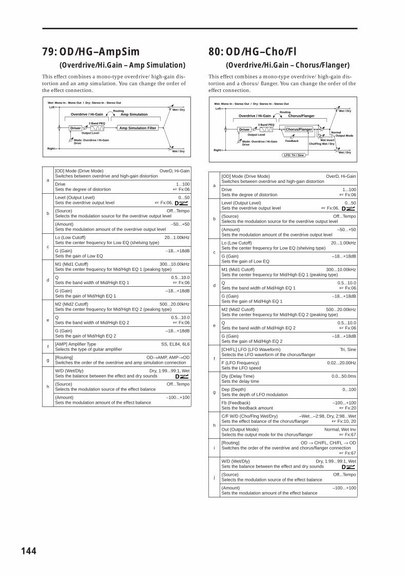
144
79: OD/HG–AmpSim(Overdrive/Hi.Gain – Amp Simulation)
This effect combines a mono-type overdrive/high-gain dis-tortion and an amp simulation. You can change the order of the effect connection.
80: OD/HG–Cho/Fl(Overdrive/Hi.Gain – Chorus/Flanger)
This effect combines a mono-type overdrive/high-gain dis-tortion and a chorus/flanger. You can change the order of the effect connection.
a
[OD] Mode (Drive Mode) OverD, Hi-GainSwitches between overdrive and high-gain distortion
DriveSets the degree of distortion
1...100☞ Fx:06
b
Level (Output Level) 0...50Sets the overdrive output level ☞ Fx:06,
(Source) Off...TempoSelects the modulation source for the overdrive output level
(Amount) –50...+50Sets the modulation amount of the overdrive output level
c
Lo (Low Cutoff) 20...1.00kHzSets the center frequency for Low EQ (shelving type)
G (Gain)Sets the gain of Low EQ
–18...+18dB
d
M1 (Mid1 Cutoff) 300...10.00kHzSets the center frequency for Mid/High EQ 1 (peaking type)
QSets the band width of Mid/High EQ 1
0.5...10.0☞ Fx:06
G (Gain)Sets the gain of Mid/High EQ 1
–18...+18dB
e
M2 (Mid2 Cutoff) 500...20.00kHzSets the center frequency for Mid/High EQ 2 (peaking type)
QSets the band width of Mid/High EQ 2
0.5...10.0☞ Fx:06
G (Gain)Sets the gain of Mid/High EQ 2
–18...+18dB
f [AMP] Amplifier TypeSelects the type of guitar amplifier
SS, EL84, 6L6
g [Routing] OD→AMP, AMP→ODSwitches the order of the overdrive and amp simulation connection
h
W/D (Wet/Dly) Dry, 1:99...99:1, WetSets the balance between the effect and dry sounds
(Source) Off...TempoSelects the modulation source of the effect balance
(Amount)Sets the modulation amount of the effect balance
–100...+100
Left
Right
Wet / Dry
Wet / Dry
Wet: Mono In - Mono Out / Dry: Stereo In - Stereo Out
+
RoutingAmp Simulation
Amp Simulation Filter
Overdrive / Hi-Gain
3 Band PEQ
Output Level
Mode: Overdrive / Hi-GainDrive
Driver
a
[OD] Mode (Drive Mode) OverD, Hi-GainSwitches between overdrive and high-gain distortion
DriveSets the degree of distortion
1...100☞ Fx:06
b
Level (Output Level) 0...50Sets the overdrive output level ☞ Fx:06,
(Source) Off...TempoSelects the modulation source for the overdrive output level
(Amount) –50...+50Sets the modulation amount of the overdrive output level
c
Lo (Low Cutoff) 20...1.00kHzSets the center frequency for Low EQ (shelving type)
G (Gain)Sets the gain of Low EQ
–18...+18dB
d
M1 (Mid1 Cutoff) 300...10.00kHzSets the center frequency for Mid/High EQ 1 (peaking type)
QSets the band width of Mid/High EQ 1
0.5...10.0☞ Fx:06
G (Gain)Sets the gain of Mid/High EQ 1
–18...+18dB
e
M2 (Mid2 Cutoff) 500...20.00kHzSets the center frequency for Mid/High EQ 2 (peaking type)
QSets the band width of Mid/High EQ 2
0.5...10.0☞ Fx:06
G (Gain)Sets the gain of Mid/High EQ 2
–18...+18dB
f
[CH/FL] LFO (LFO Waveform)Selects the LFO waveform of the chorus/flanger
Tri, Sine
F (LFO Frequency)Sets the LFO speed
0.02...20.00Hz
g
Dly (Delay Time)Sets the delay time
0.0...50.0ms
Dep (Depth)Sets the depth of LFO modulation
0...100
Fb (Feedback)Sets the feedback amount
–100...+100☞ Fx:20
h
C/F W/D (Cho/Flng Wet/Dry) –Wet...–2:98, Dry, 2:98...WetSets the effect balance of the chorus/flanger ☞ Fx:10, 20
Out (Output Mode) Normal, Wet InvSelects the output mode for the chorus/flanger ☞ Fx:67
i[Routing] OD → CH/FL, CH/FL → ODSwitches the order of the overdrive and chorus/flanger connection
☞ Fx:67
j
W/D (Wet/Dly) Dry, 1:99...99:1, WetSets the balance between the effect and dry sounds
(Source) Off...TempoSelects the modulation source of the effect balance
(Amount)Sets the modulation amount of the effect balance
–100...+100
Left
Right
Wet / Dry
Wet / Dry
Wet: Mono In - Stereo Out / Dry: Stereo In - Stereo Out
+
RoutingChorus/Flanger
Chorus/Flanger
Feedback
LFO: Tri / Sine
Cho/Flng Wet / Dry
Normal
Wet Invert
Output Mode–+
Overdrive / Hi-Gain
3 Band PEQ
Output Level
Mode: Overdrive / Hi-GainDrive
Driver

EFFE
CT
81: OD/HG–Phaser(Overdrive/Hi.Gain – Phaser)
This effect combines a mono-type overdrive/high-gain dis-tortion and a phaser. You can change the order of the effect connection.
82: OD/HG–M.Dly (Overdrive/Hi.Gain – Multitap Delay)
This effect combines a mono-type overdrive/high-gain dis-tortion and a multitap delay.
a
[OD] Mode (Drive Mode) OverD, Hi-GainSwitches between overdrive and high-gain distortion
DriveSets the degree of distortion
1...100☞ Fx:06
b
Level (Output Level) 0...50Sets the overdrive output level ☞ Fx:06,
(Source) Off...TempoSelects the modulation source for the overdrive output level
(Amount) –50...+50Sets the modulation amount of the overdrive output level
c
Lo (Low Cutoff) 20...1.00kHzSets the center frequency for Low EQ (shelving type)
G (Gain)Sets the gain of Low EQ
–18...+18dB
d
M1 (Mid1 Cutoff) 300...10.00kHzSets the center frequency for Mid/High EQ 1 (peaking type)
QSets the band width of Mid/High EQ 1
0.5...10.0☞ Fx:06
G (Gain)Sets the gain of Mid/High EQ 1
–18...+18dB
e
M2 (Mid2 Cutoff) 500...20.00kHzSets the center frequency for Mid/High EQ 2 (peaking type)
QSets the band width of Mid/High EQ 2
0.5...10.0☞ Fx:06
G (Gain)Sets the gain of Mid/High EQ 2
–18...+18dB
f
[PHS] LFO (LFO Waveform)Selects the LFO waveform of the phaser
Tri, Sine
F (LFO Frequency)Sets the LFO speed
0.02...20.00Hz
g
Manu (Manual)Sets the frequency to which the effect is applied
0...100
Dep (Depth)Sets the depth of LFO modulation
0...100
Res (Resonance)Sets the resonance amount
–100...+100☞ Fx:23
h
Phs W/D (Phaser Wet/Dry) –Wet...–2:98, Dry, 2:98...WetSets the phaser effect balance ☞ Fx:10, 23
Out (Output Mode) Normal, Wet InvSelects the phaser output mode ☞ Fx:67
i[Routing] OD → PHS, PHS → ODSwitches the order of the overdrive and phaser connection
☞ Fx:67
j
W/D (Wet/Dly) Dry, 1:99...99:1, WetSets the balance between the effect and dry sounds
(Source) Off...TempoSelects the modulation source of the effect balance
(Amount)Sets the modulation amount of the effect balance
–100...+100
Left
Right
Wet / Dry
Wet / Dry
Wet: Mono In - Stereo Out / Dry: Stereo In - Stereo Out
+
RoutingOverdrive / Hi-Gain
3 Band PEQ
Output Level
Mode: Overdrive / Hi-GainDrive
Driver
Phaser
Phaser
Resonance
LFO: Tri / Sine
Phaser Wet / Dry
Normal
Wet InvertOutput Mode
–+
a
[OD] Mode (Drive Mode) OverD, Hi-GainSwitches between overdrive and high-gain distortion
DriveSets the degree of distortion
1...100☞ Fx:06
b
Level (Output Level) 0...50Sets the overdrive output level ☞ Fx:06,
(Source) Off...TempoSelects the modulation source for the overdrive output level
(Amount) –50...+50Sets the modulation amount of the overdrive output level
c
Lo (Low Cutoff) 20...1.00kHzSets the center frequency for Low EQ (shelving type)
G (Gain)Sets the gain of Low EQ
–18...+18dB
d
M1 (Mid1 Cutoff) 300...10.00kHzSets the center frequency for Mid/High EQ 1 (peaking type)
QSets the band width of Mid/High EQ 1
0.5...10.0☞ Fx:06
G (Gain)Sets the gain of Mid/High EQ 1
–18...+18dB
e
M2 (Mid2 Cutoff) 500...20.00kHzSets the center frequency for Mid/High EQ 2 (peaking type)
QSets the band width of Mid/High EQ 2
0.5...10.0☞ Fx:06
G (Gain)Sets the gain of Mid/High EQ 2
–18...+18dB
f
[DLY] T1 (Tap1 Delay)Sets the Tap1 delay time
0...680ms
T2 (Tap2 Delay)Sets the Tap2 delay time
0...680ms
g
T1 Level (Tap1 Level)Sets the Tap1 output level
0...100☞ Fx:45
T2 Fb (Tap2 Feedback)Sets the Tap2 feedback amount
–100...+100
h
Dly W/D (Delay Wet/Dry) Dry, 2:98...98:2, WetSets the multitap delay effect balance
HiDamp (High Damp)Sets the damping amount in the high range
0...100%☞ Fx:43
i
W/D (Wet/Dly) Dry, 1:99...99:1, WetSets the balance between the effect and dry sounds
(Source) Off...TempoSelects the modulation source of the effect balance
(Amount)Sets the modulation amount of the effect balance
–100...+100
Left
Right
Wet / Dry
Wet / Dry
Wet: Mono In - Mono Out / Dry: Stereo In - Stereo Out
+
Multitap Delay
Feedback
High Damp
Delay(2)
(1)
Mt.Dly Wet / Dry
Overdrive / Hi-Gain
3 Band PEQ
Output Level
Mode: Overdrive / Hi-GainDrive
Driver
145

146
83: Wah–AmpSim(Wah/Auto Wah – Amp Simulation)
This effect combines a mono-type wah and an amp simula-tion. You can change the order of the effect connection.
84: Deci–AmpSim(Decimator – Amp Simulation)
This effect combines a mono-type decimator and an amp sim-ulation. You can change the order of the effect connection.
85: Deci–Comp(Decimator – Compressor)
This effect combines a mono-type decimator and a compres-sor. You can change the order of the effect connection.
a
[WAH] Freq Btm (Frequency Bottom)Sets the lower limit of the wah center frequency
0...100☞ Fx:09
Top (Frequency Top)Sets the upper limit of the wah center frequency
0...100☞ Fx:09
b
Swp Mode (Sweep Mode) Auto, Dmod, LFOSelects the control from auto-wah, modulation source, and LFO
☞ Fx:09,
Src (Source) Off...TempoSelects the modulation source for the wah when Swp Mode=Dmod
c lfoF (LFO Frequency)Sets the LFO speed
0.02...20.00Hz
d
ResonanceSets the resonance amount
0...100
LPF (Low Pass Filter)Switches the wah low pass filter on and off
Off, On
e [AMP] Amplifier TypeSelects the type of guitar amplifier
SS, EL84, 6L6
f [Routing] WAH → AMP, AMP → WAHSwitches the order of the wah and amp simulation connection
g
W/D (Wet/Dly) Dry, 1:99...99:1, WetSets the balance between the effect and dry sounds
(Source) Off...TempoSelects the modulation source of the effect balance
(Amount)Sets the modulation amount of the effect balance
–100...+100
a[DECI] Pre LPF Off, OnTurn the harmonic noise caused by lowered sampling on and off
☞ Fx:14
b High DampSets the ratio of high-range damping
0...100%
c Sampling Freq (Sampling Frequency)Sets the sampling frequency
1.00k...48.00kHz
d ResolutionSets the data bit length
4...24☞ Fx:14
Left
Right
Wet / Dry
Wet / Dry
Wet: Mono In - Mono Out / Dry: Stereo In - Stereo Out
+
RoutingAmp Simulation
Amp Simulation Filter
Wah/Auto Wah
Wah
D-mod
EnvelopeSweep Mode
D-modAuto
LFO
LFO
Left
Right
Wet / Dry
Wet / Dry
Wet: Mono In - Mono Out / Dry: Stereo In - Stereo Out
+
DecimatorRouting
Amp Simulation
Amp Simulation FilterPre LPF High Damp
Output Level
DecimatorResolution
e Level (Output Level)Sets the decimator output level
0...100☞ Fx:14
f [AMP] Amplifier TypeSelects the type of guitar amplifier
SS, EL84, 6L6
g [Routing] DECI→AMP, AMP→DECISwitches the order of the wah and amp simulation connection
h
W/D (Wet/Dly) Dry, 1:99...99:1, WetSets the balance between the effect and dry sounds
(Source) Off...TempoSelects the modulation source of the effect balance
(Amount)Sets the modulation amount of the effect balance
–100...+100
a
[DECI] Pre LPF Off, OnTurn the harmonic noise caused by lowered sampling on and off
☞ Fx:14
High DampSets the ratio of high-range damping
0...100%
b Sampling Freq (Sampling Frequency)Sets the sampling frequency
1.00k...48.00kHz
c ResolutionSets the data bit length
4...24☞ Fx:14
d Level (Output Level)Sets the decimator output level
0...100☞ Fx:14
e [CMP] SensitivitySets the sensitivity
1...100☞ Fx:02
f
AttackSets the attack level
1...100☞ Fx:02
Level (Output Level)Sets the compressor output level
0...100☞ Fx:02
g [Routing] DECI→CMP, CMP→DECISwitches the order of the decimator and compressor connection
h
W/D (Wet/Dly) Dry, 1:99...99:1, WetSets the balance between the effect and dry sounds
(Source) Off...TempoSelects the modulation source of the effect balance
(Amount)Sets the modulation amount of the effect balance
–100...+100
Left
Right
Wet / Dry
Wet / Dry
Wet: Mono In - Mono Out / Dry: Stereo In - Stereo Out
+
DecimatorRouting
Pre LPF High Damp
Output Level
DecimatorResolution
Compressor
CompOutput Level
Envelope - Control

EFFE
CT
86: AmpSim–Trml(Amp Simulation – Tremolo)
This effect combines a mono-type amp simulation and a trem-olo.
87: Cho/Fl–M.Dly(Chorus/Flanger – Multitap Delay)
This effect combines a mono-type chorus/flanger and a mult-itap delay.
a [AMP] Amplifier TypeSelects the type of guitar amplifier
SS, EL84, 6L6
b [TRML] LFO Wave (LFO Waveform) Triangle, Sine, Vintage, Up, DownSelects LFO Waveform ☞ Fx:32
c LFO Shape –100...+100Determines how much the LFO waveform is changed ☞ Fx:20
d Freq (LFO Frequency)Sets the LFO speed
0.02...20.00Hz
e DepthSets the depth of LFO modulation
0...100
f
W/D (Wet/Dly) Dry, 1:99...99:1, WetSets the balance between the effect and dry sounds
(Source) Off...TempoSelects the modulation source of the effect balance
(Amount)Sets the modulation amount of the effect balance
–100...+100
Left
Right
Wet / Dry
Wet / Dry
Wet: Mono In - Mono Out / Dry: Stereo In - Stereo Out
+
Amp Simulation Tremolo
Amp Simulation Filter Tremolo
LFO: Tri/Sin/Vintage/Up/Down LFO Shape
a
[CH/FL] LFO (LFO Waveform)Selects the LFO waveform of the chorus/flanger
Tri, Sine
F (LFO Frequency)Sets the LFO speed
0.02...20.00Hz
b
Dly (Delay Time)Sets the delay time
0.0...50.0ms
Dep (Depth)Sets the depth of LFO modulation
0...100
Fb (Feedback)Sets the feedback amount
–100...+100☞ Fx:20
c Pre EQ TrimSets the EQ input level
0...100
d
LoEQ (Pre Low EQ Gain)Sets the gain of Low EQ
–15...+15dB
HiEQ (Pre High EQ Gain)Sets the gain of High EQ
–15...+15dB
e C/F W/D (Cho/Flng Wet/Dry) –Wet...–2:98, Dry, 2:98...WetSets the effect balance of the chorus/flanger ☞ Fx:10, 20
f
[DLY]T1 (Tap1 Delay)Sets the Tap1 delay time
0...680ms
T2 (Tap2 Delay)Sets the Tap2 delay time
0...680ms
g
T1 Level (Tap1 Level)Sets the Tap1 output level
0...100☞ Fx:45
T2 Fb (Tap2 Feedback)Sets the Tap2 feedback amount
–100...+100
h
Dly W/D (Delay Wet/Dry) Dry, 1:99...99:1, WetSets the multitap delay effect balance
HiDamp (High Damp)Sets the damping amount in the high range
0...100%☞ Fx:43
i
W/D (Wet/Dly) Dry, 1:99...99:1, WetSets the balance between the effect and dry sounds
(Source) Off...TempoSelects the modulation source of the effect balance
(Amount)Sets the modulation amount of the effect balance
–100...+100
Left
Right
Wet / Dry
Wet / Dry
Wet: Mono In - Mono Out / Dry: Stereo In - Stereo Out
+LEQ HEQEQ
Trim
Multitap Delay
Feedback
High Damp
Delay(2)
(1)
Chorus/Flanger
Cho/FlngWet / Dry
Mt.DlyWet / Dry
Chorus/Flanger
Feedback
LFO: Tri / Sine
147
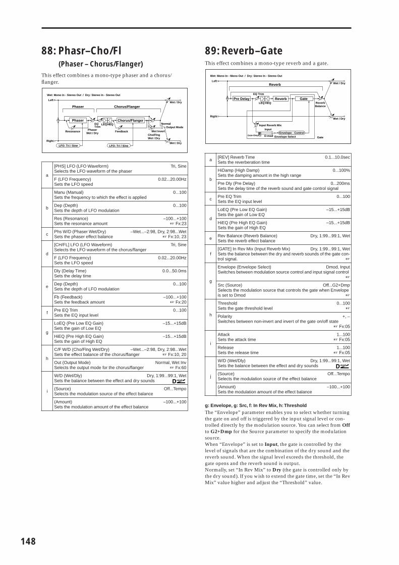
148
88: Phasr–Cho/Fl(Phaser – Chorus/Flanger)
This effect combines a mono-type phaser and a chorus/flanger.
89: Reverb–GateThis effect combines a mono-type reverb and a gate.
g: Envelope, g: Src, f: In Rev Mix, h: ThresholdThe “Envelope” parameter enables you to select whether turning the gate on and off is triggered by the input signal level or con-trolled directly by the modulation source. You can select from Off to G2+Dmp for the Source parameter to specify the modulation source. When “Envelope” is set to Input, the gate is controlled by the level of signals that are the combination of the dry sound and the reverb sound. When the signal level exceeds the threshold, the gate opens and the reverb sound is output.Normally, set “In Rev Mix” to Dry (the gate is controlled only by the dry sound). If you wish to extend the gate time, set the “In Rev Mix” value higher and adjust the “Threshold” value.
a
[PHS] LFO (LFO Waveform)Selects the LFO waveform of the phaser
Tri, Sine
F (LFO Frequency)Sets the LFO speed
0.02...20.00Hz
b
Manu (Manual)Sets the frequency to which the effect is applied
0...100
Dep (Depth)Sets the depth of LFO modulation
0...100
Res (Resonance)Sets the resonance amount
–100...+100☞ Fx:23
c Phs W/D (Phaser Wet/Dry) –Wet...–2:98, Dry, 2:98...WetSets the phaser effect balance ☞ Fx:10, 23
d
[CH/FL] LFO (LFO Waveform)Selects the LFO waveform of the chorus/flanger
Tri, Sine
F (LFO Frequency)Sets the LFO speed
0.02...20.00Hz
e
Dly (Delay Time)Sets the delay time
0.0...50.0ms
Dep (Depth)Sets the depth of LFO modulation
0...100
Fb (Feedback)Sets the feedback amount
–100...+100☞ Fx:20
f Pre EQ TrimSets the EQ input level
0...100
g
LoEQ (Pre Low EQ Gain)Sets the gain of Low EQ
–15...+15dB
HiEQ (Pre High EQ Gain)Sets the gain of High EQ
–15...+15dB
h
C/F W/D (Cho/Flng Wet/Dry) –Wet...–2:98, Dry, 2:98...WetSets the effect balance of the chorus/flanger ☞ Fx:10, 20
Out (Output Mode) Normal, Wet InvSelects the output mode for the chorus/flanger ☞ Fx:60
i
W/D (Wet/Dly) Dry, 1:99...99:1, WetSets the balance between the effect and dry sounds
(Source) Off...TempoSelects the modulation source of the effect balance
(Amount)Sets the modulation amount of the effect balance
–100...+100
Left
Right
Wet / Dry
Wet / Dry
Wet: Mono In - Stereo Out / Dry: Stereo In - Stereo Out
+
Chorus/Flanger
Cho/FlngWet / Dry
LEQHEQEQTrim
Chorus/Flanger
Feedback
Phaser
PhaserWet / Dry
Phaser
Resonance
LFO: Tri / Sine LFO: Tri / Sine
Normal
Wet InvertOutput Mode
–+
a [REV] Reverb TimeSets the reverberation time
0.1...10.0sec
b
HiDamp (High Damp)Sets the damping amount in the high range
0...100%
Pre Dly (Pre Delay) 0...200msSets the delay time of the reverb sound and gate control signal
c Pre EQ TrimSets the EQ input level
0...100
d
LoEQ (Pre Low EQ Gain)Sets the gain of Low EQ
–15...+15dB
HiEQ (Pre High EQ Gain)Sets the gain of High EQ
–15...+15dB
e Rev Balance (Reverb Balance) Dry, 1:99...99:1, WetSets the reverb effect balance
f[GATE] In Rev Mix (Input Reverb Mix) Dry, 1:99...99:1, WetSets the balance between the dry and reverb sounds of the gate con-trol signal. ☞
g
Envelope (Envelope Select) Dmod, InputSwitches between modulation source control and input signal control
☞
Src (Source) Off...G2+DmpSelects the modulation source that controls the gate when Envelope is set to Dmod ☞
h
ThresholdSets the gate threshold level
0...100☞
Polarity +, –Switches between non-invert and invert of the gate on/off state
☞ Fx:05
i
AttackSets the attack time
1...100☞ Fx:05
ReleaseSets the release time
1...100☞ Fx:05
j
W/D (Wet/Dly) Dry, 1:99...99:1, WetSets the balance between the effect and dry sounds
(Source) Off...TempoSelects the modulation source of the effect balance
(Amount)Sets the modulation amount of the effect balance
–100...+100
Left
Right
Wet / Dry
Wet / Dry
ReverbBalance
Wet: Mono In - Mono Out / Dry: Stereo In - Stereo Out
+LEQ HEQ
EQ Trim
ReverbPre Delay
Envelope - ControlD-mod
Input
Envelope Select
Gate
Input Reverb Mix
Reverb
GateGate+Dmpr

EFFE
CT
Master EQ
Master EQUse the 9–4 MasterFX MEQ page in the Program, Combina-tion, and Multi modes
You cannot use the Master EQ as the Insert Effect or as one of the Master Effects.
a: Gain, b: Gain, c: GainThese parameters are linked with the “Master EQ Gain [dB]” (9–1c) parameter of the MasterFX.
d: Low Gain Mod-SrcFor example, when this parameter is set to Kb1#17, you can con-trol the EQ gain in the range from –18dB to +18dB during perfor-mance using the [REALTIME CONTROLS] knob. At this time, set Knob 1-B to Knob Mod1 (CC#17) for “Knob B-Assign” (PROG 7–3a, COMBI 7–5a, MULTI 7–6a). The 12 o’clock position of the knob corresponds to the “Low Gain” value here.
e: High Gain Mod-SrcFor example, when this parameter is set to Kb2#19, you can con-trol the EQ gain in the range from –18dB to +18dB during perfor-mance using the [REALTIME CONTROLS] knob. At this time, set Knob 2-B to Knob Mod2 (CC#19) for “Knob B-Assign” (PROG 7–3a, COMBI 7–5a, MULTI 7–6a). The 12 o’clock position of the knob corresponds to the High Gain value here.
a
Low Cutoff 20...1.00KHzSets the cutoff frequency of Low EQ (shelving type)
Gain –18.0...+18.0 (0.5step)dBSets the gain of Low EQ
b
Mid Cutoff 300...10.00KHzSets the cutoff frequency of Mid EQ (peaking type)
Q 0.5...10.0 (0.1step)Sets the band width of Mid EQ. With a higher value, the band become narrower.
Gain –18.0...+18.0 (0.5step)dBSets the gain of Mid EQ
c
High Cutoff 500...20.00KHzSets the cutoff frequency of High EQ (shelving type)
Gain –18.0...+18.0 (0.5step)dBSets the gain of High EQ
d Low Gain Mod-SrcSelects the modulation source for Low Gain
Off...Tempo
e High Gain Mod-SrcSelects the modulation source for High Gain
Off...Tempo
Left
Right
Low Mid High
D-mod
D-mod
LEQ
Low Gain Mod.
Low Gain Mod - Src
High Gain Mod - Src
High Gain Mod.
PEQ HEQ
LEQ PEQ HEQ
L/Mono
R
149

150

7. Appendices
Ap
pen
dic
es
Alternate Modulation Source (AMS)
About Alternate ModulationAn Alternate Modulation Source can be specified for each of the 55 Alternate Modulation destinations shown in the dia-gram below. (Pitch EG is common to OSC 1 and 2.)The AMS (Alternate Modulation Source) and amount can be selected independently for each of these destinations.
About Alternate Modulation SourcesThere are 42 Alternate Modulation sources (AMS) that can control Alternate Modulation destinations.If you select two or more Alternate Modulation destinations to be controlled by the same AMS, a single source will apply modulation to each of the specified destinations.
Frequently used assignments such as using the joystick (X) or [PITCH] wheel to control pitch are already provided as dedicated parameters, so it is not necessary to use Alternate Modulation to accomplish this type of modulation routing.
OSC1 Filter1 A Filter1 B Amp 1
Pitch EG
Level Mod 1Level Mod 2Time Mod
Intensity Mod
Filter1 EG
Intensity Mod to A Intensity Mod to B
Level ModTime Mod 1Time Mod 2
Amp1 EG
Level ModTime Mod 1Time Mod 2
Cutoff Mod 1Cutoff Mod 2
Cutoff Mod 1Cutoff Mod 2
Pan Mod
LFO1 LFO2
Intensity ModIntensity Mod Intensity Mod to A
Intensity Mod to AIntensity Mod to BIntensity Mod to B Intensity Mod
Intensity Mod
Pitch Mod Resonance Mod
Frequency Mod 2Frequency Mod 1
Frequency Mod 2Frequency Mod 1
Amp Mod
OSC 1
OSC 2
Alternate Modulation
151

152
AMS (Alternate Modulation Source) List
In the above table, the parentheses ( ) indicate the type of source that can be used for each AMS.For example, the “AMS (Pitch AMS)” value for OSC1 Pitch (PROG 2–1a) can be [Off, (FEG, AEG, EXT)] (☞p.10). This means that you can select Off, and (FEG), (AEG), or (EXT) sources.
CC#: This is the control change number.*: This indicates a controller not present on the X50/microX that can be received via MIDI, such as the ribbon controller
on the TRITON Extreme etc. The controller and the type of MIDI messages it transmits will depend on the type of con-nected MIDI instrument or device.
Off do not use Alternate Modulation
(PEG) Pitch EG pitch EG
(FEG) Filter EG filter EG within the same oscillator
(AEG) Amp EG amp EG within the same oscillator
(LFO) LFO1 LFO1 within the same oscillator
(LFO) LFO2 LFO2 within the same oscillator
(KT) Flt KT +/+ (Filter Keyboard Track +/+) filter keyboard tracking within the same oscillator (☞p.153)
(KT) Flt KT +/– (Filter Keyboard Track +/–) filter keyboard tracking within the same oscillator (☞p.153)
(KT) Flt KT 0/+ (Filter Keyboard Track 0/+) filter keyboard tracking within the same oscillator (☞p.153)
(KT) Flt KT +/0 (Filter Keyboard Track +/0) filter keyboard tracking within the same oscillator (☞p.153)
(KT) Amp KT +/+ (Amp Keyboard Track +/+) amp keyboard tracking within the same oscillator (☞p.153)
(KT) Amp KT +/– (Amp Keyboard Track +/–) amp keyboard tracking within the same oscillator (☞p.153)
(KT) Amp KT 0/+ (Amp Keyboard Track 0/+) amp keyboard tracking within the same oscillator (☞p.153)
(KT) Amp KT +/0 (Amp Keyboard Track +/0) amp keyboard tracking within the same oscillator (☞p.153)
(KT) Note No. (Note Number) note number
(EXT) Velocity velocity
(EXT) MIDI Poly AT (MIDI Poly After Touch) polyphonic aftertouch received from the MIDI IN/USB connector
(EXT) MIDI AfterT (MIDI After Touch) Aftertouch (channel aftertouch) received from the MIDI IN/USB connector
(EXT) X50: Pitch Bend/microX: JS X (Joy Stick X) X50: [PITCH] wheelmicroX: Joystick X axis (horizontal)
(EXT) X50: Mod.Whl#01/microX: JS+Y #01 (Joy Stick +Y: CC#01)
X50: [MOD] wheel up direction (CC#01)microX: Joystick +Y axis (up) (CC#01)
(EXT) JS–Y #02 (Joy Stick –Y: CC#02) microX: Joystick –Y axis (down) (CC#02)
(EXT) X50: M.Whl&AT/2/microX: JS+Y&AT/2 (Joy Stick +Y & After Touch/2)
X50: [MOD] wheel up direction, and aftertouch received from the MIDI connectormicroX: Joystick +Y axis (up), and aftertouch received from the MIDI connector
(☞p.153)
(EXT) JS–Y&AT/2 (Joy Stick –Y & After Touch/2) microX: Joystick –Y axis (down), and aftertouch received from the MIDI connector (☞p.153)
(EXT) Pedal #04 (Foot Pedal: CC#04) assignable foot pedal (CC#04) (☞p.153)
(EXT) Ribbon #16 (Ribbon: CC#16) MIDI CC#16: controller (ribbon controller*)
(EXT) Slider #18 (Value Slider: CC#18) MIDI CC#18: Controller (Value Slider*)
(EXT) KnobM1#17 (Knob Mod1: CC#17) realtime control knob 1 in B-mode (knob modulation 1 CC#17) (☞p.153)
(EXT) KnobM2#19 (Knob Mod2: CC#19) realtime control knob 2 in B-mode (knob modulation 2 CC#19) (☞p.153)
(EXT) KnobM3#20 (Knob Mod3: CC#20) realtime control knob 3 in B-mode (knob modulation 3 CC#20) (☞p.153)
(EXT) KnobM4#21 (Knob Mod4: CC#21) realtime control knob 4 in B-mode (knob modulation 4 CC#21) (☞p.153)
(EXT) KnobM1 [+] (Knob Mod1: CC#17 [+]) realtime control knob 1 in B-mode [+] (☞p.153)
(EXT) KnobM2 [+] (Knob Mod2: CC#19 [+]) realtime control knob 2 in B-mode [+] (☞p.153)
(EXT) KnobM3 [+] (Knob Mod3: CC#20 [+]) realtime control knob 3 in B-mode [+] (☞p.153)
(EXT) KnobM4 [+] (Knob Mod4: CC#21 [+]) realtime control knob 4 in B-mode [+] (☞p.153)
(EXT) Damper#64 (Damper: CC#64) damper pedal (CC#64)
(EXT) Prta.SW#65 (Portamento Switch: CC#65) portamento switch (CC#65)
(EXT) Soste.#66 (Sostenuto: CC#66) sostenuto pedal (CC#66)
(EXT) Soft #67 (Soft Pedal: CC#67) soft pedal (CC#67)
(EXT) SW 1 #80 (SW1 Mod.: CC#80) X50: Assignable switch 1 (SW1 modulation CC#80) (☞p.153)
(EXT) SW 2 #81 (SW2 Mod.: CC#81) X50: Assignable switch 2 (SW2 modulation CC#81)microX: CC#81 received from the MIDI connector
(☞p.153)
(EXT) FootSW#82 (Foot Switch: CC#82) assignable foot switch (CC#82) (☞p.153)
(EXT) MIDI CC#83 MIDI control change (CC#83)
(EXT) Tempo tempo (tempo data from internal clock or external MIDI clock)

Ap
pen
dic
es
Flt KT +/+ (Filter Keyboard Track +/+)Flt KT +/– (Filter Keyboard Track +/–)Flt KT 0/+ (Filter Keyboard Track 0/+)Flt KT +/0 (Filter Keyboard Track +/0)Amp KT +/+ (Amp Keyboard Track +/+)Amp KT +/– (Amp Keyboard Track +/–)Amp KT 0/+ (Amp Keyboard Track 0/+)Amp KT +/0 (Amp Keyboard Track +/0)+/+: The direction of the effect will be determined by the sign (positive or negative) of the “Ramp Low” or “Ramp High” setting.+/–: The direction of the effect will be determined by the sign of the “Ramp Low” setting, and by the opposite sign of the “Ramp High” setting (–50 for a setting of +50, and +50 for a setting of –50).0/+: “Ramp Low” will have no AMS effect. The sign of the “Ramp High” setting will determine the direction of its effect.+/0: The sign of the “Ramp Low” setting will determine the direction of its effect. “Ramp High” will have no AMS effect.
X50: M.Whl&AT/2microX: JS+Y&AT/2 (Joy Stick +Y & After Touch/2)
X50: The effect is applied by [MOD] wheel movement in the “up” direction and by aftertouch received from the MIDI IN or USB connector. In this case, the aftertouch will pro-duce half of the specified intensity
microX: The effect is applied by joystick +Y (up) move-ment and by aftertouch received from the MIDI IN/USB
connector. In this case, the aftertouch will produce half of the specified intensity.
JS–Y&AT/2 (Joy Stick–Y & After Touch/2)
X50: The effect is applied by CC#02 and by aftertouch received from the MIDI IN/USB connector. In this case, the aftertouch will produce half of the specified intensity.
microX: The effect is applied by joystick –Y (down) move-ment, and by aftertouch received from the MIDI IN/USB connector. In this case, the aftertouch will produce half of the specified intensity.
Pedal #04 (Foot Pedal: CC#04)If you wish to use the assignable foot pedal as an AMS, set “Foot Pedal Assign” (GLOBAL 0–3a) to Foot Pedal (CC#04) (☞p.165 “Foot Pedal Assign”).A foot controller etc. connected to the ASSIGNABLE PEDAL jack will control the effect.
KnobM1#17 (Knob Mod1: CC#17)KnobM2#19 (Knob Mod2: CC#19)KnobM3#20 (Knob Mod3: CC#20)KnobM4#21 (Knob Mod4: CC#21)If you wish to use a REALTIME CONTROLS knob [1]–[4] as an AMS, make settings in program, combination, or multi set to set the Ctrls tab parameter “Knobs B Assign” to the following settings respectively: “Knob1-B” to Knob Mod.1 (CC#17), “Knob2-B” to Knob Mod.2 (CC#19), “Knob3–B” to Knob Mod.3 (CC#20), or “Knob4-B” to Knob Mod.4 (CC#21). (☞p.162 “Knob 1...4 B Assign”)When you set REALTIME CONTROLS to B-mode and oper-ate knobs [1]–[4], the specified modulation will apply.If AMS intensity is set to a positive (+) value, moving the knob to the 12 o’clock position will produce an AMS effect of 0. Rotating the knob toward the right will produce a positive change in the effect, and rotating it toward the left will pro-duce a negative change. (With negative (–) settings, the opposite effect will result.)
KnobM1 [+] (Knob Mod1: CC#17 [+] )KnobM2 [+] (Knob Mod2: CC#19 [+] )KnobM3 [+] (Knob Mod3: CC#20 [+] )KnobM4 [+] (Knob Mod4: CC#21 [+] )These differ from KnobM1#17–KnobM4#21 in the knob position and direction of the effect. If AMS intensity is set to a positive (+) value, rotating the knob to the far left will pro-duce an AMS effect of 0. Rotating the knob toward the right will apply an effect only in the positive direction. (With neg-ative (–) settings, the opposite effect will result.)
SW 1 #80 (SW1 Mod.: CC#80)SW 2 #81 (SW2 Mod.: CC#81)
X50: If you wish to use either [SW1] or [SW2] as an AMS, make settings in the program, combination, or multi set to set the Ctrls page parameter “SW1/2 Assign” to the follow-ing values respectively: “SW1” to SW1 Mod.(CC#80), or “SW2” to SW2 Mod.(CC#81) (☞p.161 “X50: SW1/2 Assign”). These are controlled by [SW1] or [SW2].
Foot SW #82 (Foot Switch: CC#82)If you wish to use an assignable foot switch as an AMS, set “Foot SW Assign” (GLOBAL 0–3a) to Foot SW (CC#82) (☞p.164 “Foot Switch Assign”).The effect will be controlled when you operate a foot switch etc. connected to the ASSIGNABLE SWITCH jack.
Note Number
Amp
Key Low Key High
AMS = Amp KT +/+AMS Intensity = positive (+) value
Ramp Low= +50
Ramp High= +50
Depth and direction of modulation
zero
+ max
- max
example of Amp Keyboard Track settings
AMS = Amp KT +/–AMS Intensity = positive (+) value
Depth and direction of modulation
zero
+ max
- max
AMS = Amp KT 0/+AMS Intensity = positive (+) value
Depth and direction of modulation
zero
+ max
- max
AMS = Amp KT +/0AMS Intensity = positive (+) value
Depth and direction of modulation
zero
+ max
- max
153

154
Alternate Modulation settingsWhen you operate an AMS (Alternate Modulation Source), the modulation destination will be affected as shown in the table below.
By using alternate modulation, you can create complex sys-tems of modulation in which EG, LFO, keyboard tracks, and controllers work together.
• You can apply complex change to an LFO or EG, for example by using the pitch/filter/amp EG to control the frequency or intensity of an LFO that modulates the pitch/filter/amp, or by using LFO2 to control the frequency of LFO1.
• The tone, EG, and LFO etc. can be controlled not only by velocity or joystick (or [PITCH] wheel), but also from a switch, knob, or pedal etc.
• Panning can be controlled in realtime from a controller, EG, or LFO etc.
• The filter EG can also be used to control pitch or volume at the same time as it controls the filter.
• Controllers etc. can be used to control EG levels or times. This lets you shape the EG in realtime.
• Filter/amp keyboard tracking or note number can be used to control the EG or LFO according to the keyboard pitch that is played.
• Pitch, tone, EG or LFO can be controlled by the tempo of the arpeggiator.
Notes for the table on the lower right*1 If Note No. is selected as an “AMS,” the base value will
be C4.*2 EXT(+) : Velocity, MIDI PolyAT, MIDI AfterT, Mod.
Whl#01/JS+Y #01, JS–Y #02, JS+Y&AT/2, M.Whl&AT/2/JS –Y&AT/2, Pedal #04, Slider #18, KnobM1[+], KnobM2[+], KnobM3[+], KnobM4[+], Damper #64, Porta.SW #65, Soste. #66, Soft #67, SW 1 #80, SW 2 #81, MIDI CC#83
*3 EXT(+–): KnobM1 #17, KnobM2 #19, KnobM3 #20, KnobM4 #21
*4 If Tempo is selected as an AMS, the base value will be � =120. For example if the AMS for “Pitch” is set to Tempo, and “AMS Intensity” is set to 12.00, doubling the tempo value (� =120 → 240) will raise the pitch one octave, and halving the tempo (� =120 → 60) will lower the pitch one octave.
*5 A dedicated parameter is also provided.*6 This will be added to the “Filter Frequency” value. As
the “Filter Frequency” value increases by 10, the cutoff frequency will double (rise one octave).
*7 This will be added to the “Pan” setting.*8 It is possible to control LFO “Frequency” by using
Tempo and “AMS Intensity.” However if you use the “Sync. (MIDI/Tempo Sync.)” function (PROG 3–1c), the LFO frequency can be synchronized to the tempo and note value.
The effect of alternate modu-lation on various parameters, and example applications
Pitch (PROG 2–1a)Pitch can be controlled by the filter/amp EG, controllers, or tempo etc.
• If you select Filter EG or Amp EG as the “AMS (Pitch AMS)” and set “Intensity (AMS Intensity)” to +12.00, the pitch will change up to ±1 octave in synchronization with the EG.
• If you select Tempo as the “AMS (Pitch AMS)” and set “Intensity (AMS Intensity)” to +12.00, doubling the tempo (based on � =120) will raise the pitch one octave, and halving the tempo will lower the pitch one octave.
Pitch EG Intensity (PROG 2–1b)Pitch EG intensity can be controlled by keyboard tracking, controllers, or tempo.
• X50: If you set “AMS” (Pitch EG AMS) to Mod.Whl#01, and set “Intensity (AMS Intensity)” to +12.00, moving the [MOD] wheel up will gradually increase the effect of the Pitch EG up to a maximum of ±1 octave. Setting “Intensity (AMS Intensity)” to a negative value will invert the effect of the Pitch EG.
• microX: If you select JS+Y#01 as the “AMS (Pitch EG AMS)” and set “Intensity (AMS Intensity)” to +12.00, moving the joystick, in the +Y direction will gradually increase the effect of the Pitch EG to a maximum of ±1 octave. If “Intensity (AMS Intensity)” has a negative value, the effect of the Pitch EG will be inverted.
Pitch LFO1/2 Intensity (PROG 2–2a) Pitch modulation intensity of the LFO1/2 can be controlled by an EG, keyboard tracking, controllers, or tempo etc.
• If you select EG as the “AMS (LFO1/2 AMS),” the pitch change width of LFO modulation etc. can be controlled in synchronization with the level changes of the EG. With positive (+) settings of “Intensity (AMS Intensity),” the vibrato effect will gradually deepen as the EG level rises, or gradually lessen as the EG level decreases. With negative (–) settings of “Intensity (AMS Intensity),” the LFO phase will be inverted.
• X50: If you select a controller such as SW1 or SW2 as the “AMS (LFO 1/2 AMS),” you can press when desired to turn on the vibrato effect.
• microX: If you set “AMS (LFO1/2 AMS)” to a controller such as Foot SW#82, you can apply a vibrato effect on when desired by simply stepping on a foot switch connected to the ASSIGNABLE SWITCH jack.
Parameter
AMS →AMS Value →
AMS Intensity
PEG/FEG –99...0...+99
AEG 0...+99
PitchPitch EG Int.Pitch LFO1/2 Int.
(+12.00)(+12.00)(+12.00)
–1...0...+1[Octave] –
–1...0...+1[Octave]
0...+1[Octave] –
0...+1[Octave]
Filter Frequency *6ResonanceFilter EG Int.Filter LFO1/2 Int.
(+99)(+99)(+99)(+99)
–99...0...+99 –99...0...+99
– –99...0...+99
0...+990...+99
–0...+99
AmpAmp LFO1/2 Int.Pan *7
(+99)(+99)(+50)
value x(0...1...8) –99...0...+99 –63...0...+63
–0...+990...+63
EG LevelEG TimeLFO Frequency
(+66)(+49)(+99)
– –
value x(1/64...1...64)
– –
value x(1...64)

Ap
pen
dic
es
Filter (Cutoff) Frequency (PROG 4–1b, 5–1b)The cutoff frequency of filter A/B can be controlled by the pitch/amp EG, controllers, or tempo. Set “AMS 1/2 (Filter A/B AMS1/2)” and “AMS 1/2 Intensity” for Filter A or B.
• X50: If you set “AMS1 (Filter A AMS1)” to Pitch Bend, and set “Intensity (A AMS1 Intensity)” to a positive (+) value, moving the [PITCH] wheel in the up direction will raise the cutoff, and moving it in the down direction will lower the cutoff. Negative (–) settings will produce the opposite effect.
• microX: If you set “AMS1 (Filter A AMS1)” to JS X, and set “Intensity (A AMS1 Intensity)” to a positive (+) value, moving the joystick toward the right will raise the cutoff frequency, and moving it toward the left will lower the cutoff frequency. Negative (–) settings will have the opposite result.
• If you select the same controller for “AMS” and set the Filter A (Low Pass Filter) “Intensity (A AMS 1/2 Intensity)” parameter and Filter B (High Pass Filter) “Intensity (B AMS 1/2 Intensity)” parameter to different values, a single controller operation will simultaneously control the cutoff frequencies of the two filters.
Resonance (PROG 4–1b)This can be used when the “Type (Filter1/2 Type)” is Low Pass Resonance. The resonance level can be controlled by EG, LFO, keyboard tracking, controllers or tempo etc.
• If you select Filter KT or Amp KT as the “Reso.AMS (Resonance AMS),” you can use the filter or amp keyboard tracking settings to control the resonance level. For example if the amp keyboard tracking parameters “Low (KBDTrk Ramp Low)” and “High (KBDTrk Ramp High)” are set to positive (+) values, Amp KT +/+ is selected as the “Reso.AMS (Resonance AMS),” and “Intensity (AMS Intensity)” it set to a positive (+) value, playing toward either end of the keyboard will cause amp keyboard tracking to increase the volume, and “Reso.AMS (Resonance AMS)” to raise the resonance level.
• You can select a controller as the “Reso.AMS (Resonance AMS),” and apply resonance when desired by operating the controller.
• You can select LFO1 or 2 as the “Reso.AMS (Resonance AMS),” and use the LFO to modulate the resonance level.
Filter EG Intensity (PROG 4–2b)Filter EG intensity can be controlled by a controller or tempo etc. You can use “Int. to A (AMS Int. to A)” and “Int. to B (AMS Int. to B)” to independently specify the intensity for Filter A and B.
• X50: If you set “AMS (Filter EG AMS)” to Mod.Whl#01, and set “Int. to A/B (AMS Int. to A/B)” to a positive (+) value, moving the [MOD] wheel up will gradually increase the effect of the Filter EG. Setting “Int. to A/B (AMS Int. to A/B)” to a negative (–) value will invert the effect of the Filter EG.
• microX: If you select JS–Y#02 as the “AMS (Filter EG AMS)” and set “Int. to A/B (AMS Int. to A/B)” to a positive (+) value, moving the joystick down (the –Y direction) will gradually increase the effect of the Filter EG. If you set “Int. to A/B (AMS Int. to A/B)” to a negative (–) value, the effect of the Filter EG will be inverted.
• If you select Ribbon#16 as the “AMS (Filter EG AMS)” and set “Int. to A/B (AMS Int. to A/B)” to a positive (+) value, operating the ribbon controller on a connected MIDI instrument, such as the TRITON Extreme, toward the right will gradually increase the effect of the Filter EG. Operating the ribbon controller on a connected MIDI instrument, such as the TRITON Extreme, toward the left will gradually increase the effect of the Filter EG with an inverted phase.
Filter LFO 1/2 Intensity (PROG 4–4a)The LFO 1/2 filter modulation intensity can be controlled by EG, keyboard tracking, controller, or tempo. You can use “Int. to A (LFO1/2 AMS Int. to A)” and “Int. to B (LFO1/2 AMS Int. to B)” to independently specify the intensity for Filter A and B.
• If you select EG as the “AMS (LFO1/2 AMS),” the auto-wah effect produced by LFO modulation will be controlled by the changes in EG level. If you set “Int. to A (LFO1/2 AMS Int. to A)”/“Int. to B (LFO1/2 AMS Int. to B)” to a positive (+) value, the wah effect will deepen as the EG level rises, and will lessen as the EG level falls. With negative (–) values of “Int. to A (LFO1/2 AMS Int. to A)”/“Int. to B (LFO1/2 AMS Int. to B),” the phase of the LFO will be inverted.
• X50: If you use a controller such as SW1 or 2 as the “AMS (LFO1/2 AMS),” you can apply the auto-wah effect when desired by pressing [SW1] or [SW2].
• microX: If you set “AMS (LFO1/2 AMS)” to a controller such as Foot SW#82, you can apply an auto wah effect by using a foot switch connected to the ASSIGNABLE SWITCH jack.
LFO1/2 –99...0...+99
KT(Flt KT, Amp KT) –99...0...+99
KT(Note No.) *1...36(C2)...60(C4)...84(C6)
...
Pitch Bend/JS X/Ribbon#16 –Max...0...+Max
EXT(+) *20...127
EXT(+–) *3 –Max...0...+Max
EXT(Tempo) *4( � ) = ...60...120...240...
dedicated parameter – –
–1...0...+1[Octave] –1...0...+1[Octave] –1...0...+1[Octave]
dedicated parameter ...–1...0...+1...[Octave] ...–1...0...+1...[Octave]
–1...0...+1[Octave] *5 –1...0...+1[Octave] –1...0...+1[Octave]
0...+1[Octave]0...+1[Octave]0...+1[Octave]
–1...0...+1[Octave]–1...0...+1[Octave]–1...0...+1[Octave]
...–1...0...+1...[Octave]
...–1...0...+1...[Octave]
...–1...0...+1...[Octave]
dedicated parameter –99x2...0...+99x2
– –
– –99...0...+99
– –99...0...+99
–...–99...0...+99...
–...–99...0...+99...
–99...0...+99 –99...0...+99 –99...0...+99 –99...0...+99
0...+990...+990...+990...+99
–99...0...+99 –99...0...+99 –99...0...+99 –99...0...+99
...–99...0...+99...
...–99...0...+99...
...–99...0...+99...
...–99...0...+99...
dedicated parameter –
–127...0...+127
– –99...0...+99 –63...0...+63
–...–99...0...+99... ...–63...0...+63...
value x(0...1...8) –99...0...+99 –63...0...+63
value x(1...8)0...+990...+63
value x(0...1...8) –99...0...+99 –63...0...+63
value x(0...1...8...) ...–99...0...+99... ...–63...0...+63...
– –
value x(1/128...1...128)
–99...0...+99value x(1/64...1...64)value x(1/64...1...64)
–99...0...+99value x(...1/64...1...64...)value x(...1/64...1...64...)
–99...0...+99value x(1/64...1...64)value x(1/64...1...64)
0...+99value x(1...64)value x(1...64)
–99...0...+99value x(1/64...1...64)value x(1/64...1...64)
–99...0...+99value x(...1/64...1...64...)
value x(...1/64...1...64...) *8
155

156
Amp (PROG 6–2(5)b)The volume can be controlled by the pitch/filter EG, con-trollers, or tempo etc.
• If an EG or controller that changes with a positive (+) value (Amp EG, EXT(+), EXT(SW)) is selected as the “AMS (Amp AMS),” setting the “Int (AMS Intensity)” to +99 will allow you to increase the volume to a maximum of eight times that of the current volume.
• If an EG, LFO, or controller that changes with a ± value (Pitch EG, Filter EG, LFO, KT, EXT(+–) is selected as the “AMS (Amp AMS),” setting the “Int (AMS Intensity)” to +99 will allow you to increase the volume to a maximum of eight times that of the current volume (for positive (+) changes of the AMS), or to decrease the volume to zero (for negative (–) changes of the AMS).
• In addition to the time-variant changes in volume produced by the amp EG, you can also make the volume change in synchronization with the pitch/filter EG. Select PitchEG or FilterEG as the “AMS (Amp AMS),” and adjust “Int (AMS Intensity).” If you wish to cancel the effect of the AmpEG and use the pitch/filter EG to control the volume, set all levels of the AmpEG to +99.
Amp LFO 1/2 Intensity (PROG 6–2(5)b)The amp modulation intensity of LFO 1/2 can be controlled by EG, keyboard tracking, controllers, or tempo etc.
• If you select EG as the “AMS (LFO1/2 AMS),” the depth of the tremolo effect produced by LFO modulation will change in synchronization with the changes in EG level. If you set “Int. (AMS Intensity)” to a positive (+) value, the tremolo effect will deepen as the EG level rises, and lessen as the EG level falls. If “Int. (AMS Intensity)” is set to a negative (–) value, the phase of the LFO will be inverted.
• X50: If select a controller such as SW1 or 2 as the “AMS (LFO1/2 AMS),” you can apply the tremolo effect by pressing [SW1] or [SW2] when desired.
• microX: If you set “AMS (LFO1/2 AMS)” to a controller such as Foot SW#82, you can apply a tremolo effect just when you want by using a foot switch connected to the ASSIGNABLE SWITCH jack.
Pan (PROG 6–1(4)b)The oscillator pan can be controlled by EG, LFO, keyboard tracking, controllers, or tempo etc.
• If you select Note No. as the “AMS (Pan AMS)” and set “Intensity” to +50, panning will be controlled by the keyboard position: center at the C4 note, far right at C6 or above, and far left at C2 or below.
• If EG is selected as the “AMS (Pan AMS),” the oscillator pan will be controlled in synchronization with the changes in EG level. If “Intensity” is set to a positive (+) value, the pan will move toward the right as the EG level increases, and toward the left as the EG level decreases. If “Intensity” is set to a negative (–) value, the opposite effect will occur.
EG Level – Pitch EG (PROG 2–5b)– Filter EG (PROG 4–5b, 5–5b)– Amp EG (PROG 6–3b)
EG levels can be controlled by keyboard tracking, control-lers, or tempo etc.
Set the “I (AMS Intensity)” value, and select +/–/0 for each EG segment (“S” start, “A” attack, “B” break) to specify the direction of the effect (if any) on that segment.+: AMS will function according to the Intensity setting. –: The sign of the Intensity setting will be inverted.0: AMS will have no effect.If “I (AMS Intensity)” is set to +66, the various EG levels can be controlled over a maximum range of ±99.
• Set “AMS” to Velocity for Amp EG Level Modulation, “I (AMS Intensity)” to +66, “S” to 0, “A” to +, and “B” to –. Set all Amp EG levels to +00. As you play with increasing velocity, the EG levels will change more greatly. At the maximum velocity, the Start Level will stay at +00, but the Attack Level will change to +99 and the Break Level will change to –99.
EG Time – Pitch EG (PROG 2–5c)– Filter EG (PROG 4–5c, 5–5c)– Amp EG (PROG 6–3c)
EG times can be controlled by keyboard tracking, control-lers, or tempo etc. Set the “I (AMS Intensity)” value, and select +/–/0 for each EG segment (“A” attack, D” decay, “S” slope, “R” release) to specify the direction of the effect (if any) on that segment.+: AMS will function according to the Intensity setting.–: The sign of the Intensity setting will be inverted. 0: AMS will have no effect.Each EG time is determined by the Alternate Modulation value at the moment that the corresponding EG point is reached. For example, the Alternate Modulation value at the moment that the Attack Level is reached will determine the Decay Time.If “I (AMS Intensity)” is set to a value of 8, 17, 25, 33, 41, or 49, the corresponding time can be multiplied by a maximum of 2, 4, 8, 16, 32, or 64 times (or divided by 1/2, 1/4, 1/8, 1/16, 1/32, 1/64).
• X50: Suppose that you set “AMS” to Mod.Whl#01, “I (AMS Intensity)” to +8, “A” to +, “D” to –, and “S” and “R” to 0. Moving the [MOD] wheel up will lengthen the attack time to a maximum of double its original length. The Decay Time will be shortened by a maximum of 1/2. The Slope and Release times will not change.
• microX: Select JS+Y#01 for “AMS,” and set “I (AMS Intensity)” to +8, “A” to +, “D” to –, and “S” and “R” to 0. When you move the joystick in the +Y direction, the Attack Time will be lengthened by a maximum of 2 times. The Decay Time will be shortened by a maximum of 1/2. The Slope and Release times will not change.

Ap
pen
dic
es
LFO Frequency (PROG 3–1b)The frequency of LFO 1 or 2 can be controlled by EG, key-board tracking, controllers, or tempo etc., You can even use the LFO2 frequency to modulate the LFO1 frequency.If “Int (AMS 1/2 Intensity)” is set to a value of 16, 33, 49, 66, 82, or 99, the corresponding frequency can be multiplied by a maximum of 2, 4, 8, 16, 32, or 64 times (or divided by 1/2, 1/4, 1/8, 1/16, 1/32, 1/64).
• X50: If you set “AMS 1/2 (Freq. AMS 1/2)” to Mod.Whl#01 and set “Int (AMS 1/2 Intensity)” to +16, moving the [MOD] wheel in the up direction will lengthen the LFO cycle to a maximum of double its original length. If you set “Int (AMS 1/2 Intensity)” to –16, moving the [MOD] wheel in the up direction will shorten the LFO cycle to as little as half of its original length.
• microX: Select JS+Y#01 for “AMS1/2 (Freq. AMS1/2),” and set “Int (AMS1/2 Intensity)” to +16. When you move the joystick in the +Y direction, the LFO frequency will be increased by a maximum of 2 times. If you set “Int (AMS1/2 Intensity)” to –16 and move the joystick in the +Y direction, the LFO frequency will be decreased by up to 1/2.
Dynamic Modulation Source (Dmod)
You can control certain effect parameters using the joystick (or [MOD] wheel), REALTIME CONTROLS knobs, etc. “on the fly.” Controlling effects in this way is referred to as Dynamic Modulation. This lets you use effects expressively as a part of the instrument. For example you can use a pedal connected to the X50/microX to speed up the LFO of a cho-rus or flanger, or use the joystick (or [MOD] wheel) to con-trol wah.Most of the parameters for dynamic modulation consist of parameter values for “(Source)” and “(Amount).” The “(Source)” field selects the modulation source, and “(Amount)” sets the amount of dynamic modulation effect. When the modulation source is set to the maximum value, the actual degree of the effect will be the parameter value plus the “(Amount)” value.
Example: “W/D (Wet/Dry)” 10:90, “(Source)” Pdl#4, “(Amount)” +50
In this case, the effect balance is 10:90. As you apply After Touch, the percentage of the effect sound will increase. When After Touch is at its maximum, the effect balance will be 60:40.
The dynamic modulation effect will not be affected if you modify the “(Amount)” value while dynamic mod-ulation is being applied. The change will become effec-tive when you operate the dynamic modulation source again.
Refer to the corresponding effect section for an explanation of other dynamic modulation parameters.In the table of parameters for each effect, dynamic modula-tion parameters are marked by a symbol at the right of the parameter.
Wet / Dry
MaxZero Higher
D-mod
Dry
Wet
60:40
10:90
Dynamic Modulation (Example)
Wet / Dry=10:90Amt= +50
Wet / Dry=60:40Amt= –50
157

158
Dynamic Modulation Source List
CC#: This is the control change number.*: This indicates a controller not present on the X50/
microX that can be received via MIDI, such as the ribbon controller on the TRITON Extreme etc. The controller and the type of MIDI messages it transmits will depend on the type of connected MIDI instrument or device.
In Program mode, dynamic modulation of the insert effect and master effects is controlled on the global MIDI channel.In Combination mode and Multi mode, dynamic mod-ulation of the insert effect and master effects are con-trolled on the MIDI channel that has been specified as the “Control Channel” for IFX, MFX1, and MFX2 respectively.
Source name Explanation
Off dynamic modulation is not used
Gate1 note on/off (☞p.159)
G1+Dmp (Gate1+Damper) note on + damper on/off (☞p.159)
Gate2 note on/off (retrigger) (☞p.159)
G2+Dmp (Gate2+Damper) note on + damper on/off (retrigger) (☞p.159)
Note No. (Note Number) note number
Vel (Velocity) Velocity
AfterT (After Touch) after touch (Channel After Touch)
X50: PBend/microX: JS X (Joy Stick X) X50: [PITCH] wheel microX: Joystick X axis (horizontal)
X50: M.Whl#1/microX: JS+Y#1 (Joy Stick +Y: CC#01) X50: [MOD] wheel microX: Joystick +Y (up) (CC#01)
JS–Y#2 (Joy Stick –Y: CC#02) X50: CC#02*microX: Joystick –Y (down) (CC#02)
Pdl#4 (Foot Pedal: CC#04) assignable foot pedal (CC#04) (☞p.159)
FX1#12 (FX Control1: CC#12) MIDI effect control 1(CC#12)
FX2#13 (FX Control2: CC#13) MIDI effect control 2(CC#13)
Rbn#16 (Ribbon: CC#16) MIDI CC#16: controller (ribbon controller*)
Sld#18 (Value Slider: CC#18) MIDI CC#18: Controller (Value Slider*)
Kb1#17 (Knob Mod1: CC#17) realtime control knob 1 in B-mode (knob modulation 1 CC#17) (☞p.159)
Kb2#19 (Knob Mod2: CC#19) realtime control knob 2 in B-mode (knob modulation 2 CC#19) (☞p.159)
Kb3#20 (Knob Mod3: CC#20) realtime control knob 3 in B-mode (knob modulation 3 CC#20) (☞p.159)
Kb4#21 (Knob Mod4: CC#21) realtime control knob 4 in B-mode (knob modulation 4 CC#21) (☞p.159)
Kb1[+] (Knob Mod1: CC#17 [+]) realtime control knob 1 in B-mode [+] (☞p.159)
Kb2[+] (Knob Mod2: CC#19 [+]) realtime control knob 2 in B-mode [+] (☞p.159)
Kb3[+] (Knob Mod3: CC#20 [+]) realtime control knob 3 in B-mode [+] (☞p.159)
Kb4[+] (Knob Mod4: CC#21 [+]) realtime control knob 4 in B-mode [+] (☞p.159)
Dmp#64 (Damper: CC#64) damper pedal (CC#64)
Prt#65 (Portamento Switch: CC#65) portamento switch (CC#65)
Sos#66 (Sostenuto: CC#66) sostenuto pedal (CC#66)
SW1#80 (SW1 Mod.: CC#80) assignable panel switch 1 (SW1 modulation CC#80) (☞p.159)
SW2#81 (SW2 Mod.: CC#81) assignable panel switch 2 (SW2 modulation CC#81) (☞p.159)
FSW#82 (Foot Switch: CC#82) assignable foot switch (CC#82)
CC#83 MIDI Control Change (CC#83)
Tempo tempo (internal clock or external MIDI clock tempo data) (☞p.159)

Ap
pen
dic
es
Gate1, G1+Dmp (Gate1+Damper)The effect is at maximum during note-on, and will stop when all keys are released. With G1+Dmp, the effect will remain at maximum even after the keys are released, as long as the damper (sustain) pedal is pressed.
Gate2, G2+Dmp (Gate2+Damper)This is essentially the same as for Gate 1 or G1+Dmp. How-ever when Gate 2 or G2+Dmp are used as a dynamic modu-lation source for the EG of 22: St.Env.Flanger etc. or the AUTOFADE of 27: St.Vibrato, a trigger will occur at each note-on. (In the case of Gate 1 and G1+Dmp, the trigger occurs only for the first note-on.)
Pdl#4 (Foot Pedal: CC#04)If you wish to use the assignable foot pedal as a dynamic modulation source, set “Foot Pedal Assign” (GLOBAL 0–3a) to Foot Pedal (CC#04). (☞p.165 “Foot Pedal Assign”)A foot controller etc. connected to the ASSIGNABLE PEDAL jack can be used to control an effect.
Kb1#17 (Knob Mod1: CC#17)Kb2#19 (Knob Mod2: CC#19)Kb3#20 (Knob Mod3: CC#20)Kb4#21 (Knob Mod4: CC#21)If you want to use the REALTIME CONTROLS [1]–[4] knobs as dynamic modulation sources in Pattern, Combination, Multi modes, access the 7: Ed–Arp/Ctrls page, and in “Knob B Assign,” set “Knob1-B” to Knob Mod.1 (CC#17), “Knob2-B Assign” to Knob Mod.2 (CC#19), “Knob3-B Assign” to Knob Mod.3 (CC#20), and “Knob4-B Assign” to Knob Mod.4 (CC#21). (☞p.162 “Knob 1...4 B Assign”)When you set REALTIME CONTROLS to B-mode and oper-ate knobs [1]–[4], the effect will be controlled.Moving the knob to the 12 o’clock position will produce a effect of 0 as the dynamic modulation source. If “(Amount)” is a positive (+) value, rotating the knob toward the right will produce a positive change in the effect, and rotating it toward the left will produce a negative change. (With nega-tive (–) values, the opposite effect will result.)
Kb1[+] (Knob Mod1: CC#17 [+] )Kb2[+] (Knob Mod2: CC#19 [+] )Kb3[+] (Knob Mod3: CC#20 [+] )Kb4[+] (Knob Mod4: CC#21 [+] )These differ from Kb1#17 (Knob Mod1: CC#17)–Kb4#21 (Knob Mod4: CC#21) in the knob position and direction of the effect. If “(Amount)” is set to a positive (+) value, rotat-ing the knob to the far right will produce an effect of 0 as the dynamic modulation source. Rotating the knob toward the right will apply an effect only in the positive direction. (With negative (–) settings, the opposite effect will result.)
SW1#80 (SW1 Mod.: CC#80)SW2#81 (SW2 Mod.: CC#81)
X50: If you want to use [SW1] and [SW2] as dynamic mod-ulation sources in Program, Combination, Multi modes, access the 7: Ed–Arp/Ctrls page, and in “SW1/2 Assign,” set “SW1” to SW1 Mod. (CC#80) and “SW2” to SW2 Mod. (CC#81). (☞p.161 “X50: SW1/2 Assign”)The effect will be controlled when you operate [SW1] or [SW2].
FSW#82 (Foot Switch: CC#82)If you wish to use an assignable foot switch as a dynamic modulation source, set “Foot SW Assign” (GLOBAL 0–3a) to Foot SW (CC#82) (☞p.164 “Foot Switch Assign”).The effect will be controlled when you operate a foot switch etc. connected to the ASSIGNABLE SWITCH jack.
TempoModulation sources other than Tempo are internally pro-cessed as a value of 0–127 (–128 – +127). In contrast, Tempo uses the tempo data (BPM value) of the internal clock or the external MIDI clock. This means that when “� ” is 127 (BPM), it will have the same result as the maximum value (+127) of other modulation sources.
Gate1, G1+Dmp
Gate1
Note
Dmpr1 2 31 2 3
Damper Pedal
G1+Dmp
Time
OnOff
Gate2, G2+Dmp
Gate2
Note
Dmpr1 2 31 2 3
Damper Pedal
G2+Dmp
Time
OnOff
159

160
About the BPM/MIDI SYNC functionBPM/MIDI SYNC can be used for most effects that have an LFO, such as 09:St. Wah/Auto Wah, and for some delay-type effects such as 49:L/C/R BPM Delay. You can apply modulation that is synchronized to the tempo, or specify the delay time in terms of a note value so that the effect will syn-chronize to the tempo of the arpeggiator during a live per-formance even if you change the tempo.Parameters that allow BPM/MIDI SYNC to be used are marked by a symbol at their right in the list of param-eters for each effect.
Example 1. LFO“BPM/MIDI Sync” On“Base (Base Note)“ �“Times” 1In this case, each cycle of the LFO will be as long as one quarter note.
If “BPM” is set to MIDI, the effect will synchronize to the tempo of the arpeggiator or to an external MIDI clock. If “BPM” is in the range of 40–240, the specified value will be used.
Example 2. Delay Time“L Bs (Base Note)” �“Times” 1“R Bs (Base Note)” �“Times” 3In this case, the delay time of the left channel will be the duration of an eighth note, and the delay time of the right channel will be the duration of a sixteenth note triplet.
When “BPM” is set to MIDI, the effect will synchronize to the tempo of the arpeggiator or to an external MIDI clock. If “BPM” is in the range of 40–240, the specified value will be used.If the tempo, “Bs (Base Note),” and “Times” settings in con-junction would cause the maximum delay time to be exceeded, the warning “TimeOver? >OVER!” will appear in the display. Please modify your settings so that this setting does not appear. (The maximum delay time will depend on the effect type.)
BPM/MIDI Sync: LFOLFO
BPM/MIDI Sync: Delay Time
Lch
Rch
Dry Wet
Dry Wet
Ap
pen
dic
es
X50: SW1/2 Assign
The following functions can be assigned to the assignable switches [SW1] and [SW2].
• For a program, combination, or multi set make the settings in 7: Ed–Arp/Ctrls page “SW1/2 Assign” (PROG 7–3a, COMBI 7–5b, MULTI 7–5b).
This can be set for each program in Program mode, each combination in Combination mode, and each multi set in Multi mode.
SW1, SW2 Assign List
SW1 Mod.(CC#80) (SW1 Modulation:CC#80)SW2 Mod.(CC#81) (SW2 Modulation:CC#81)This effect differs between SW1 and SW2. SW1 is handled as CC#80, and SW2 is handled as CC#81.
Porta.SW(CC#65) (Portamento Switch:CC#65)When “Mode (Oscillator Mode)” (PROG 1–1a) is Single, turning the switch on (LED lit) will apply portamento regardless of the “Enable (Porta. Enable)” (PROG 2–1c) set-ting, and turning the switch off (LED off) will not apply por-tamento.If “Mode (Oscillator Mode)” is Double, and if the “Enable (Porta. Enable)” setting is the same for OSC1 and 2 (i.e., Enable or Disable for both OSC1 and 2), then portamento will be applied to OSC1 and 2 when the switch is turned on (LED lit), and portamento will not be applied to OSC1 and 2 when the switch is turned off (LED off).If the “Enable (Porta. Enable)” setting is different for OSC1 and 2 (i.e., OSC1 is Enable and OSC2 is Disable, or OSC1 is Disable and OSC2 is Enable), then portamento will be applied to the OSC whose setting is Enable when the switch is turned on (LED lit), and portamento will be applied to neither OSC when the switch is turned off (LED off).
Pitch Bend LockThe state of the [PITCH] wheel will alternate between Lock and Unlock (Lock when the LED is lit).While the [PITCH] wheel is being operated, turning Lock on will lock (fix) the effect at the current position of that con-troller.
For example if you move the [PITCH] wheel in the up direc-tion and turn Lock on, the [PITCH] wheel movement will be locked (held) at that position, so that modulation will con-tinue to be applied even if you return the [PITCH] wheel to its original position. By continuing to operate the [PITCH] wheel, you can apply both types of modulation simulta-neously.
When you Lock the [PITCH] wheel will be halted, but reception will still occur.
Off no function
SW1 Mod.(CC#80) (SW1 Modulation:CC#80)SW2 Mod.(CC#81) (SW2 Modulation:CC#81)
Select this when using the switch as an Alternate Modulation or Effect Dynamic Modulation source. In this case, you must first specify the control destination. Each time the switch is turned On/Off, a CC#80 (or CC#81) message will be transmitted (Off: 0, On: 127).
Porta.SW(CC#65) (Portamento Switch:CC#65) When you press SW1 (or SW2) to turn it on (LED lit), portamento will be applied. Each time this is turned On/Off, CC#65 will be transmitted (Off: 0, On: 127).
Octave Down Each time you press SW1 (or SW2), the pitch will alternate between 1 octave lower and the original octave setting (1 octave down when the LED is lit).
Octave Up Each time you press SW1 (or SW2), the pitch will alternate between 1 octave higher and the origi-nal octave setting (1 octave up when the LED is lit).
Pitch Bend Lock the effect of [PITCH] wheel
161

162
Knob 1...4 B Assign
The following functions can be assigned to the REALTIME CONTROLS [1]–[4] knobs in B-mode.
• For program, combination, or multi set, make these settings in 7: Ed–Arp/Ctrls page “Knob B Assign.”
This can be set for each program in Program mode, each combination in Combination mode, and each multi set in Multi mode.
Realtime Control Knobs B Assign ListOff No function
Knob Mod. 1 (CC#17) General purpose controller. Alternate Modulation or Effect Dynamic Modulation can be controlled. To use this, select KnobM1#17 for “AMS,” or Kb1#17 for “Dmod Src.” Simultaneously, CC#17 will be transmitted.
Knob Mod. 2 (CC#19) General purpose controller. Alternate Modulation or Effect Dynamic Modulation can be controlled. To use this, select KnobM2#19 for “AMS,” or Kb2#19 for “Dmod Src.” Simultaneously, CC#19 will be transmitted.
Knob Mod. 3 (CC#20) General purpose controller. Alternate Modulation or Effect Dynamic Modulation can be controlled. To use this, select KnobM3#20 for “AMS,” or Kb3#20 for “Dmod Src.” Simultaneously, CC#20 will be transmitted.
Knob Mod. 4 (CC#21) General purpose controller. Alternate Modulation or Effect Dynamic Modulation can be controlled. To use this, select KnobM4#21 for “AMS,” or Kb4#21 for “Dmod Src.” Simultaneously, CC#21 will be transmitted.
Master Volume Control the volume. Simultaneously, the universal system exclusive message Master Volume [F0H, 7FH, nn, 04, 01, vv, mm, F7H] will be transmitted to adjust the volume of all tracks or timbres (while preserving the volume bal-ance between tracks or timbres).
Porta. Time (CC#05) Control the portamento time. Simultaneously, CC#5 will be transmitted.
Volume (CC#07) Control the volume. Simultaneously, CC#7 will be transmitted.
IFX Pan (CC#08) Control the panning after the insertion effect. Simultaneously, CC#8 will be transmitted.
Pan (CC#10) Control the oscillator panning. Simultaneously, CC#10 will be transmitted.
Expression (CC#11) Control the expression. Simultaneously, CC#11 will be transmitted.
FX Ctrl 1 (CC#12) Control Effect Dynamic Modulation. When controlling this, set “Dmod Src” to FX1#12. Simultaneously, CC#12 will be transmitted.
FX Ctrl 2 (CC#13) Control Effect Dynamic Modulation. When controlling this, set “Dmod Src” to FX2#13. Simultaneously, CC#13 will be transmitted.
Flt Cutoff (CC#74) Control the cutoff frequency of the Filter (low pass filter). Simultaneously, CC#74 will be transmitted.
Flt Reso. (CC#71) Control the resonance of the Filter, or the cutoff frequency of the high pass filter. If the program’s “Type (Filter1/2 Type)” is Low Pass Resonance, the resonance level will be controlled. If it is Low Pass & High Pass, the cutoff frequency of the high pass filter will be controlled. Simultaneously, CC#71 will be transmitted.
Flt EG Int. (CC#79) Control the EG intensity of the Filter. Simultaneously, CC#79 will be transmitted.
F/A Attack (CC#73) Control the EG attack of the Filter and Amplifier. Simultaneously, CC#73 will be transmitted.
F/A Decay (CC#75) Control the EG decay time and slope time of the Filter and Amplifier. Simultaneously, CC#75 will be transmitted.
F/A Sus. (CC#70) Control the EG sustain level of the Filter and Amplifier. Simultaneously, CC#70 will be transmitted.
F/A Rel. (CC#72) Control the EG release time of the Filter and Amplifier. Simultaneously, CC#72 will be transmitted.
P LFO1 Spd (CC#76) Control the frequency of LFO1. Simultaneously, CC#76 will be transmitted.
P LFO1 Dep (CC#77) Control the LFO1 intensity of the pitch. Simultaneously, CC#77 will be transmitted.
P LFO1 Dly (CC#78) Control the delay of LFO1. Simultaneously, CC#78 will be transmitted.
SW 1 Mod. (CC#80) General-purpose controller. Alternate Modulation or Effect Dynamic Modulation can be controlled. To control these, set “AMS” or “Dmod Src” to SW 1 #80. Simultaneously, CC#80 will be transmitted.
SW 2 Mod. (CC#81) General-purpose controller. Alternate Modulation or Effect Dynamic Modulation can be controlled. To control these, set “AMS” or “Dmod Src” to SW 2 #81. Simultaneously, CC#81 will be transmitted.
Foot SW (CC#82) General-purpose controller. Alternate Modulation or Effect Dynamic Modulation can be controlled. To use this, select FootSW#82 for “AMS,” or FSW#82 for “Dmod Src.” Simultaneously, CC#82 will be transmitted.
MIDI CC#83 (CC#83) General-purpose controller. Alternate Modulation or Effect Dynamic Modulation can be controlled. To use this, select MIDI CC#83 for “AMS,” or CC#83 for “Dmod Src.” Simultaneously, CC#83 will be transmitted.
MFX Send 1 (CC#93) Control the send level to Master Effect1. Simultaneously, CC#93 will be transmitted.
MFX Send 2 (CC#91) Control the send level to Master Effect2. Simultaneously, CC#91 will be transmitted.
MIDI CC#00...CC#95 The specified MIDI control change (CC#) will be transmitted. If this instrument is set so as to be controlled by the control change message, the corresponding control will occur.

Ap
pen
dic
es
The A-mode functions of the REALTIME CONTROLS are fixed.
Knob1-A: LPF Cutoff (Filter LPF Cutoff: CC#74)Control the low pass filter cutoff frequency of the filter. Simultaneously, CC#74 will be transmitted.
Knob2-A: Resonance/HPF (Filter Resonance/HPF Cutoff: CC#71)
Control the resonance level or the cutoff frequency of the high pass filter. If the program “Filter Type” is Low Pass Resonance, the resonance level will be controlled. If “Filter Type” is Low Pass & High Pass, the cutoff frequency of the high pass filter will be controlled. Simultaneously, CC#71 will be transmitted.
Knob3-A: EG-Intensity (Filter EG Intensity: CC#79)Control the filter EG intensity. Simultaneously, CC#79 will be transmitted.
Knob4-A: EG-Release (Filter, Amplifier EG Release: CC#72)
Control the release time of the filter and amplifier EG. Simultaneously, CC#72 will be transmitted.
163

164
Foot Switch Assign
You can assign the function of an assignable switch (sepa-rately sold Korg PS-1 option) connected to the ASSIGN-ABLE SWITCH jack.
• This setting is made in GLOBAL 0: System Foot page “Foot SW Assign” (0–3a).
If you select a function that includes a CC#, that MIDI control change message will be transmitted each time the switch is turned on/off. (Off: 0, On: 127)
Foot Switch Assign List
Portamento SW (CC#65)When the “Mode (Oscillator Mode)” (PROG 1–1a) is Single, turning the switch on will apply portamento regardless of the “Enable (Porta. Enable)” (PROG 2–1c) setting, and turn-ing the switch off will not apply portamento.If “Mode (Oscillator Mode)” is Double, and if the “Enable (Porta. Enable)” setting is the same for OSC1 and 2 (i.e., Enable or Disable for both OSC1 and 2), then portamento will be applied to OSC1 and 2 when the switch is turned on, and portamento will not be applied to OSC1 and 2 when the switch is turned off.If the “Enable (Porta. Enable)” setting is different for OSC1 and 2 (i.e., OSC1 is Enable and OSC2 is Disable, or OSC1 is Disable and OSC2 is Enable), then portamento will be applied to the OSC whose setting is Enable when the switch is turned on, and portamento will be applied to neither OSC when the switch is turned off.
Even if you set “Foot SW Assign” to Knob1...4, you can-not use a connected foot switch to control the REAL-TIME CONTROLS C-mode arpeggiator effect. Nor will it transmit MIDI control messages.
Tap tempo control can be used whenever the [TEMPO] knob can be operated.
Off The connected foot switch will not function.
Foot SW (CC#82) Alternate Modulation or Effect Dynamic Modulation can be controlled. To control these, select Foot SW:#82 for “AMS” or FSW#82 for “Dmod Src.”
Portamento SW (CC#65) Control portamento on/off.
Sostenuto (CC#66) Control the sostenuto effect (which holds only the keys (Note No.) that were being held at the moment that the pedal switch was turned on).
Soft (CC#67) Turn the soft pedal effect on/off.
Arpeggio SW Turn the arpeggiator on/off. The NRPN message [Bn 63 00 Bn 62 02 Bn 06 00 (off) or 7F (on)] will be transmitted each time this is turned on/off.
Program Up The switch can be used to select programs or combinations. When in PROG 0: Play, the program that follows the currently selected program will be selected. When in COMBI 0: Play, the combina-tion that follows the currently selected combination will be selected. Simultaneously, a Bank Select message and Program Change message will be transmitted.
Program Down The switch can be used to select programs or combinations. When in PROG 0: Play, the program that precedes the currently selected program will be selected. When in COMBI 0: Play, the combi-nation that precedes the currently selected combination will be selected. Simultaneously, a Bank Select message and Program Change message will be transmitted.
X50: Mod.Wheel (CC#01)/microX: JS+Y (CC#01)
X50: The switch will control the effect of the “up” direction of the [MOD] wheel.microX: The switch will control the effect of the +Y (up) direction of the joystick.
JS–Y (CC#02) X50: The switch will control Alternate Modulation or Effect Dynamic Modulation. To control these, choose JS–Y#2 for “AMS,” or JS–Y#2 for “Dmod Src.”microX: The switch will control the effect of the –Y (down) direction of the joystick.
After Touch The switch will control aftertouch.
Knob 1...4 The switch will control the effect of REALTIME CONTROLS knobs [1]–[4]. (On produces the same effect as when the knob is rotated fully right, and Off as when it is rotated fully left.)
X50: SW1, 2/microX: SW1 (CC#80), SW2 (CC#82)
X50: The switch will control the effect of [SW1] or [SW2].microX: The switch will control Alternate Modulation or Effect Dynamic Modulation. To control these, choose SW1 #80 or SW2 #81.
TAP TEMPO This switch can be used to control the tempo of the arpeggiator in realtime.

Ap
pen
dic
es
Foot Pedal Assign
You can assign the function that will be controlled by an assignable pedal (separately sold Korg XVP-10 or EXP-2 option) connected to the ASSIGNABLE PEDAL jack.
• This setting is made in GLOBAL 0: System Foot page “Foot Pedal Assign” (0–3a).
If you select a function that includes a CC#, that MIDI control change message will be transmitted each time the pedal is operated. (min: 0, max: 127)
Foot Pedal Assign List
Even if you set “Foot Pedal Assign” to Knob1...4, you cannot use a connected foot switch to control the REAL-TIME CONTROLS C-mode arpeggiator effect. Nor will it transmit MIDI control messages.
Off The connected pedal will not function.
Master Volume Control the volume. Simultaneously, the universal exclusive message Master Volume [F0H, 7FH, nn, 04, 01, vv, mm, F7H] will be transmitted to control the volume of all timbres or tracks (while pre-serving the volume balance between timbres or tracks).
Foot Pedal (CC#04) Alternate Modulation or Effect Dynamic Modulation can be controlled. To control these, set “AMS” to Pedal #04 or “Dmod Src” to Pdl#04.
Portamento Time (CC#05) Control the speed at which portamento will change the pitch.
Volume (CC#07) Control the volume of a Program, of a timbre in a Combination, or of a track in Multi mode.
Post IFX Pan (CC#08) Control the pan after passing through the insertion effect.
Pan (CC#10) Control the pan of a Program, of a timbre in a Combination, or of a track in Multi mode.
Expression (CC#11) Control the volume of a Program, of a timbre in a Combination, or of a track in Multi mode. Expres-sion is multiplied with the Volume value to determine the actual volume level.
FX Control 1 (CC#12) Control Effect Dynamic Modulation. To control this, set Dmod Src to FX1#12.
FX Control 2 (CC#13) Control Effect Dynamic Modulation. To control this, set Dmod Src to FX2#13.
MFX Send 1 (CC#93) Control the send level to master effect 1 (MFX1) from a Program, a timbre in a Combination, or a track in Multi mode. Simultaneously, this will also control the send level to master effect 1 (MFX1) from after the insertion effect of the matching MIDI channel.
MFX Send 2 (CC#91) Control the send level to master effect 2 (MFX2) from a Program, a timbre in a Combination, or a track in Multi mode. Simultaneously, this will also control the send level to master effect 2 (MFX2) from after the insertion effect of the matching MIDI channel.
X50: Mod.Wheel (CC#01)/microX: JS+Y (CC#01)
X50: The pedal will control the effect of the “up” direction of the [MOD] wheel.microX: The pedal will control the effect of the +Y (up) direction of the joystick.
JS–Y (CC#02) X50: The pedal will control Alternate Modulation or Effect Dynamic Modulation. To control these, choose JS–Y#2 for “AMS,” or JS–Y#2 for “Dmod Src.”microX: The pedal will control the effect of the –Y (down) direction of the joystick.
After Touch The pedal will control aftertouch.
Knob 1...4 Pedal operation will control the effect of REALTIME CONTROLS knobs [1]–[4].
165

166
MIDI transmission when the X50/microX’s control-lers are operated
The following table shows the relation between the MIDI messages that are transmitted when the X50/microX’s con-trollers are operated, and the AMS (alternate modulation source) or DMS (dynamic modulation source) that corre-spond to each MIDI message. # indicates a fixed function, and * indicates an assignable function.When one of the X50/microX’s controllers is operated, the corresponding or the assigned control change will be trans-mitted. Pitch bend messages are transmitted only when you operate the X-axis of the joystick (microX) or the [PITCH] wheel (X50). Operation in each mode is described below. (The explanation mentions only control changes, but the same applies to pitch bend messages.)
Program modeWhen one of the X50/microX’s controllers is operated, a control change message will be transmitted on the global MIDI channel.
If a REALTIME CONTROLS B-mode knob [1]–[4] is set to Master Volume, the universal exclusive message Master Volume will be transmitted.
Combination modeWhen one of the X50/microX’s controllers is operated, a control change message will be transmitted on the global MIDI channel.Simultaneously, the message will also be transmitted on the MIDI channel (“MIDI Channel” COMBI 2–1a) of any timbre whose “Status” (COMBI 2–1a) is EXT or EX2.When one of the X50/microX’s controllers is operated, its effect will apply to any timbre whose “Status” is INT and whose “MIDI Channel” setting is either Gch or the same as the global MIDI channel.
In the case of Master Volume, the universal exclusive message Master Volume will be transmitted only on the global MIDI channel.
You can make settings for MIDI Filter (COMBI 3, 4) to enable or disable control changes and controllers for each timbre. When checked, the above operations will be enabled.
Effect dynamic modulation can be controlled when the “Control Ch (Control Channel)” (COMBI 8–1b) setting for IFX, MFX1, 2, or MEQ is either set to Gch or to the same channel as the global MIDI channel. (In the case of All Rt., control is possible on the MIDI channel of any routed tim-bre.)
Multi modeWhen one of the X50/microX’s controllers is operated, its effect will apply to the track 1–16 that is selected by “Control Track” (MULTI 0–1a).
If the “Status” (MULTI 2–1a/2a) of the track selected by “Control Track” is EXT, EX2, or BTH, a control change mes-sage will be transmitted on the MIDI channel specified by “MIDI Channel” (MULTI 2–1a/2a).If the “Status” is INT or BTH, operating one of the X50/microX’s controllers will affect only that track. Simulta-neously, the same effect will also apply to any track with the same “MIDI Channel” setting.
In the case of Master Volume, the universal exclusive message Master Volume will be transmitted.
You can make settings for MIDI Filter (MULTI 3, 4) to enable or disable control changes and controllers for each track. When checked, the operations effective for a “Status” of INT or BTH will be enabled. Tracks whose “Status” is EXT, EX2, or BTH will transmit control changes regardless of this setting.
Effect dynamic modulation can be controlled when the “Control Ch (Control Channel)” (MULTI 8–1b) setting for IFX, MFX1, 2, or MEQ matches the MIDI channel of the track selected by “Control Track.” (In the case of All Rt., control is possible on the MIDI channel of all routed tracks.)If one of the X50/microX’s controllers is operated during realtime recording, the corresponding or assigned control change will be recorded on the external MIDI seuencer etc.

Ap
pen
dic
es
The following table shows the relation between the MIDI messages that are transmitted when the X50/microX’s con-trollers are operated, and the AMS (alternate modulation
source) or DMS (dynamic modulation source) that corre-spond to each MIDI message. # indicates a fixed function, and ✽ indicates an assignable function.
X50/microX controller Available for AMS
Available for DMODJoy
Stick(microX)
[PITCH] Wheel (X50)
[MOD] Wheel (X50)
R.T.C.A
R.T.C.B
R.T.C. Value
Valve On/Off
Gate Knob
Velocity Knob
SW1,2(X50)
ARP On/Off
Damper Switch Pedal
MIDI channel messagesNote-offNote-on (note number) ✽ ✽
Note-on (velocity) ✽ ✽
Poly after touch ✽
CC#0 Bank select (MSB) ✽
1 Modulation 1 # (+Y) # ✽ ✽ ✽ ✽ ✽
2 Modulation 2 # (–Y) ✽ ✽ ✽ ✽ ✽
3 – ✽
4 Foot controller ✽ ✽ ✽ ✽
5 Portamento time ✽ ✽
6 Data entry (MSB) ✽
7 Volume ✽ ✽
8 Post insertion effect pan ✽ ✽
9 – ✽
10 Pan ✽ ✽
11 Expression ✽ ✽
12 Effect control 1 ✽ ✽ ✽
13 Effect control 2 ✽ ✽ ✽
14...15 ✽
16 Ribbon controller ✽ ✽ ✽ ✽ ✽
17 Knob modulation 1 ✽ ✽ ✽
18 Controller (CC#18) # ✽ ✽ ✽ ✽ ✽
19 Knob modulation 2 ✽ ✽ ✽
20 Knob modulation 3 ✽ ✽ ✽
21 Knob modulation 4 ✽ ✽ ✽
22...31 – ✽
32 Bank select (LSB) ✽
33...37 – ✽
38 Data entry (LSB) ✽
39...63 – ✽
64 Damper ✽ # ✽ ✽
65 Portamento On/Off ✽ ✽ ✽ ✽ ✽
66 Sostenuto On/Off ✽ ✽ ✽ ✽
67 Soft ✽ ✽ ✽
68...69 – ✽
70 Sustain level ✽
71 Filter resonance level/High pass filter cutoff frequency
✽ (Knob2) ✽
72 Release time ✽ (Knob4) ✽
73 Attack time ✽
74 Low pass filter cutoff frequency ✽ (Knob1) ✽
75 Decay time ✽
76 LFO1 speed ✽
77 LFO1 depth (pitch) ✽
78 LFO1 delay ✽
79 Filter EG intensity ✽ (Knob3) ✽
80 SW1 modulation On/Off ✽ ✽ (SW1) ✽ ✽ ✽
81 SW2 modulation On/Off ✽ ✽ (SW2) ✽ ✽ ✽
82 Foot switch On/Off ✽ ✽ ✽ ✽
83 Controller (CC#83) ✽ ✽ ✽
84...90 - ✽
91 Effect depth 1 (send 2 level) ✽ ✽
92 Effect depth 2 (insertion effect On/Off) ✽
93 Effect depth 3 (send 1 level) ✽ ✽
94 Effect depth 4 (master effect 1 On/Off) ✽
95 Effect depth 5 (master effect 2 On/Off) ✽
96 Data increment97 Data decrement98 NRPN(LSB)
2: Arpeggiator on/off switch # ✽
10: Arpeggiator gate control #11: Arpeggiator velocity control #
99 NRPN(MSB) 0 # # # # # ✽
100 RPN(LSB)0: Bend range1: Fine tune2: Coarse tune
101 RPN(MSB) 0102...127 -
Program change ✽
Channel after touch ✽ ✽ ✽ ✽
Bender change # (X) # ✽ ✽
Universal exclusiveMaster volume ✽ ✽
Master balanceMaster fine tuneMaster coarse tune
167

168
X50/microX operations when control changes are transmitted/received
The following table shows the operations that the X50/microX will perform when control change messages are
received, and the relation between settings and controller movements on this instrument
CC# Control Value Function
0 Bank select (MSB) 0...127 bank select message MSB
1 Modulation 1 0...127 X50: Corresponds to [MOD] wheel movement in the up directionmicroX: Corresponds to joystick movement in the +Y (up ) direction
2 Modulation 2 0...127 X50: Used to control Alternate Modulation (corresponds to AMS: JS–Y #02) or Effect Dynamic Modulation (corresponds to Dmod Src: JS–Y#2)microX: Corresponds to joystick movement in the –Y direction (down)
4 Foot controller 0...127 corresponds to when the assignable pedal function is set to Foot Pedal
5 Portamento time 0...127 portamento time
6 Data entry (MSB) 0...127 MSB of RPN and NRPN data *1
7 Volume 0...127 volume *2
8 Post insertion effect pan 0...127 pan after the insertion effect
10 Pan 0...127 pan
11 Expression 0...127 volume *2
12 Effect control 1 0...127 for controlling Effect Dynamic Modulation (same as Dmod Src: FX1 #12)
13 Effect control 2 0...127 for controlling Effect Dynamic Modulation (same as Dmod Src: EX2 #13)
16 Controller (CC#16) 0...127 for controlling Modulation, Alternate Modulation (same as AMS: Ribbon #16), Effect Dynamic Modulation (same as Dmod Src Rbn#16)
17 Knob modulation 1 0...127 corresponds to when Knob Mod.1 is assigned as the B-mode function of a REALTIME CONTROLS knob
18 Controller (CC#18) 0...127 for controlling Alternate Modulation (same as AMS: Slider #18), Effect Dynamic Modula-tion (same as Dmod Src: Sld #18)
19 Knob modulation 2 0...127 corresponds to when Knob Mod.2 is assigned as the B-mode function of a REALTIME CONTROLS knob
20 Knob modulation 3 0...127 corresponds to when Knob Mod.3 is assigned as the B-mode function of a REALTIME CONTROLS knob
21 Knob modulation 4 0...127 corresponds to when Knob Mod.4 is assigned as the B-mode function of a REALTIME CONTROLS knob
32 Bank select (LSB) 0...127 LSB of bank select message
38 Data entry (LSB) 0...127 LSB of RPN or NRPN data *1
64 Damper 0...127 damper effect
65 Portamento On/Off 0...63(Off), 64...127(On) turn the portamento effect on/off
66 Sostenuto On/Off 0...63(Off), 64...127(On) turn the sostenuto effect on/off
67 Soft 0...127 soft pedal effect
70 Sustain level 0...127 sustain levels of the filter EG and amp EG *3
71 Filter resonance levelHigh pass filter cutoff frequency
0...127 resonance level of the filtercutoff frequency of the high pass filter
*4*3
72 Release time 0...127 release times of the filter EG and amp EG *3
73 Attack time 0...127 attack times of the filter EG and amp EG *3
74 Low pass filter cutoff frequency 0...127 cutoff frequency of the low pass filter *3
75 Decay time 0...127 decay times/slope times of the filter EG and amp EG *3
76 LFO1 speed 0...127 LFO1 speed *3
77 LFO1 depth 0...127 pitch LFO1 intensity *3
78 LFO1 delay 0...127 LFO1 delay *3
79 Filter EG intensity 0...127 filter EG intensity *3
80 Panel switch1 On/Off 0...63(Off), 64...127(On) X50: Corresponds to On/Off when the SW1 function is set to SW1 Mod.microX: Used to control Alternate Modulation and Effect Dynamic Modulation
81 Panel switch2 On/Off 0...63(Off), 64...127(On) X50: Corresponds to On/Off when the SW2 function is set to SW2 Mod.microX: Used to control Alternate Modulation and Effect Dynamic Modulation
82 Foot switch On/Off 0...63(Off), 64...127(On) corresponds to on/off when the function of the assignable foot switch is set to Foot SW
83 Controller (CC#83) 0...127 for controlling Alternate Modulation (same as AMS: MIDI CC#8), Effect Dynamic Modulation (same as Dmod Src: CC#83)
91 Effect depth 1 (send 2 level) 0...127 send 2 level
92 Effect depth 2 (insertion effect On/Off) 0(Off), 1...127(On) turn insertion effect on/off *5
93 Effect depth 3 (send 1 level) 0...127 send 1 level
94 Effect depth 4 (master effect 1 On/Off) 0(Off), 1...127(On) master effect 1 on/off *5
95 Effect depth 5 (master effect 2 On/Off) 0(Off), 1...127(On) master effect 2 on/off *5
96 Data increment 0
97 Data decrement 0
98 NRPN(LSB) 21011
corresponds to the arpeggiator on/off switchcorresponds to the arpeggiator Gate control knobcorresponds to the arpeggiator Velocity control knob
*6*6*6
99 NRPN (MSB) 0 MSB of NRPN
100 RPN(LSB) 012
select the pitch bend rangeselect Fine Tuneselect Coarse Tune
*1*1*1
101 RPN(MSB) 0 MSB of RPN

Ap
pen
dic
es
Any control change number (CC#00–95) can be assigned as the B-mode function of a REALTIME CON-TROLS knob. In this case, the transmitted values will all be 0–127.
*1 Unlike conventional control changes, pitch bend range, fine tune, and coarse tune settings are made using RPC (Registered Parameter Control) messages. In Program, Combination, and Multi modes, you can use RPC mes-sages to control the bend range and tuning for each pro-gram, combination (Combination), or track (Multi). The procedure is to use an RPN (Registered Parameter Num-ber) message to select the parameter that you wish to edit, and then use Data Entry to input a value for that parameter. To select the parameter, use CC#100 (with a value of 00–02) and CC#101 (with a value of 00). use CC#06 and CC#38 to enter the data.The data entry values for each parameter and the corre-sponding settings are as follows.
For example, if in Multi mode you wish to set a track that is receiving channel 1 to a transpose (coarse tuning) value of –12, you would first transmit [B0, 64, 02] (64H=CC#100) and [B0, 65, 00] (65H=CC#101) to this instrument to select the RPN coarse tune. Then you would set this to –12 by transmitting [B0, 06, 34] (06H=CC#6), 34H=52 (corresponds to –12), and [B0, 26, 00] (26H=CC#38, 00H=0).
*2 The volume of the X50/microX is determined by sum-ming the Volume (CC#07) with the Expression (CC#11).
*3 A value of 64 will correspond to the value specified by the program parameter. 0 will be the minimum, and 127 will be the maximum. Changing from 63–1 or from 65–126 will adjust the effect from the program parameter setting toward the minimum value or maximum value. The internal program parameters listed in (*3, *4) will be con-trolled.
*4 If the filter type of the corresponding program is Low Pass Resonance, the filter resonance level will be con-trolled. If the filter type is Low Pass & High Pass, the cutoff frequency of the high pass filter will be controlled.
*3, *4CC#70–79 correspond to the following program parame-ters of the X50/microX.
In Program mode, when CC#70–79 is received on the global MIDI channel (“MIDI Channel” GLOBAL 1–1a), or when a REALTIME CONTROLS [1]–[4] knob is oper-ated in A-mode or in B-mode when the function is assigned to CC#70–79, the corresponding program parameter will be edited temporarily. You can execute “Write Program” (PROG 0–1) to save that state (except for some parameters). When you execute “Write Pro-gram,” the values of the corresponding program param-eters will be rewritten.
In Combination, Multi modes, the program parameters of the program for the timbre and track of the corre-sponding MIDI channel will change, but this state can not be saved directly in the program.
CC#70: Sustain levelCorresponds to “Filter/Amp EG Sustain Level” (PROG 4/5: Ed–Filter1/2, EG page, 6: Ed–Amp1/2, EG page).
CC#71: Filter resonance level/High pass filter cutoff frequencyCorresponds to “Filter A Resonance” (PROG 4/5: Ed–Filter1/2, Basic page).Corresponds to “Filter B Frequency” (PROG 4/5: Ed–Filter1/2, Basic page).
CC#72: Release timeCorresponds to “Filter/Amp EG Release Time” (PROG 4/5: Ed–Filter1/2, EG page, 6: Ed–Amp1/2, EG page).
CC#73: Attack timeCorresponds to Filter/Amp EG Attack Time” (PROG 4/5: Ed–Filter1/2, EG page, 6: Ed–Amp1/2, EG page)Corresponds to “Amp EG Start Level” (PROG 6: Ed–Amp1/2, EG page).Corresponds to “Amp EG Attack Level” (PROG 6: Ed–Amp1/2, EG page).Corresponds to “Amp EG Level Modulation Start” (PROG 6: Ed–Amp1/2, EG page).Corresponds to “Amp EG Time Modulation Attack” (PROG 6: Ed–Amp1/2, EG page).
CC#74: Low pass filter cutoff frequencyCorresponds to “Filter A Frequency” (PROG 4/5: Ed–Filter1/2, EG page).Corresponds to “Filter B Frequency” (PROG 4/5: Ed–Filter1/2, EG page).
CC#75: Decay timeCorresponds to “Filter/Amp EG Decay Time” (PROG 4/5: Ed–Filter1/2, EG page, 6: Ed–Amp1/2, EG page)Corresponds to “Filter/Amp EG Slope Time” (PROG 4/5: Ed–Filter1/2, EG page, 6: Ed–Amp1/2, EG page)
CC#76: LFO1 speedCorresponds to “LFO 1 Frequency” (PROG 3: Ed–LFOs, OSC1/2, LFO1 page).
CC#77: LFO1 depth (pitch LFO1 intensity)Corresponds to “Pitch LFO1 Intensity” (PROG 2: Ed–Pitch, OSC1LFO page).
CC#78: LFO1 delayCorresponds to “LFO1 Delay” (PROG 3: Ed–LFOs, OSC1/2, LFO1 page).
CC#79: Filter EG intensityCorresponds to “Filter EG Intensity to A, B” (PROG 4/5: Ed–Filter1/2, Mod.1 page).
CC#06 CC#38
0001
12
0000
0
0+ 1
+12
CC#06 CC#3840
52
64
88
00
00
00
00
–24
–12
0
+24
CC#06 CC#38
32
48
64
96
00
00
00
00
–50
–25
0
+50
RPN=0 (Pitch bend range)
RPN=1 (Fine tune)
RPN=2 (Coarse tune)
Parameter value (Semitone steps)
Parameter value (Semitone steps)
Parameter value (1 cent steps)
169

170
*5 Controlled on the global MIDI channel.*6 NRPN (Non Registered Parameter Number) and Data
Entry can be used to control the following parameters.
Arpeggiator on/off[Bn 63 00 Bn 62 02 Bn 06 nn] (nn:00–3F off, 40–7F on)
Arpeggiator gate control[Bn 63 00 Bn 62 0A Bn 06 nn] (nn:00–7F)
Arpeggiator velocity control[Bn 63 00 Bn 62 0B Bn 06 nn] (nn:00–7F)

Ap
pen
dic
es
MIDI applications
■ Messages transmitted and received by this instrument
[...] indicates hexadecimal notation
MIDI channelsMIDI messages can be exchanged when the transmitting and receiving devices are set to the same MIDI channel. MIDI uses sixteen channels, numbered 1–16. The way in which channels are handled will differ depending on the mode.
Program mode• Transmission/reception is performed on the global
MIDI channel*.
* The global MIDI channel is the basic channel that this instrument uses for MIDI transmission/reception, and is set by “MIDI Channel” (GLOBAL 1–1a).
Combination mode• The global MIDI channel is used to transmit/receive
messages for selecting a combination and turning effects on/off, and to transmit/receive exclusive data.
• The MIDI channel specified for each timbre (in COMBI 2–1a) is used to transmit/receive MIDI data for each timbre.
• The MIDI channel specified for the insert effect and master effects (in MIDI channel “Control Ch (control Channel)” (COMBI 8–2b)) is used to control dynamic modulation, and to control the pan and send 1/2 after the sound has passed through the insert effects.
• When you operate the keyboard or controllers of the X50/microX, messages will be transmitted on the global MIDI channel, and will also be transmitted on the MIDI channel of any timbre whose “Status” (COMBI 2–1a) is set to EXT or EX2.
• Channel messages will be received if they match the MIDI channel of a timbre whose “Status” is set to INT (☞p.40 “Status” and “MIDI Channel”).
Multi mode• The global MIDI channel is used to transmit/receive
exclusive data and for messages that switch effects on/off.
• MIDI data of each track is transmitted/received on the MIDI channel specified for each track (In Multi mode, this will be the settings of MULTI 2–1(2)a.)
• The MIDI channel specified for the insert effect and master effects (in MULTI 8–3b) is used to control dynamic modulation, and to control the pan and send 1/2 after the sound has passed through the insert effect.
• When you operate the keyboard or controllers of the X50/microX, messages will be transmitted on the MIDI channel selected by “Control Track” (MULTI 0–1a). However, messages will be transmitted only if the track selected by “Control Track” has a “Status” of BTH, EXT, or EX2. ( ☞p.56 “Control Track”– )
• Tracks whose “Status” is INT or BTH will receive channel messages of the matching MIDI channel (☞p.61 “Status” and “MIDI Channel”).
Note on/off
Note-on [9n, kk, vv]Note-off [8n, kk, vv](n: channel, kk: note number, vv: velocity)
When you play a note on the X50/microX’s keyboard, it will transmit note-on/off messages. When the arpeggiator is running, note-on/off messages will be transmitted by the arpeggiator. (If Local Control is off, the arpeggiator will not transmit note-on/off data. ☞OG p.32 “Local Control On set-tings”)Most devices do not transmit or receive note-off velocity, and the X50/microX does not transmit or receive this data either.
Program Change/Bank Select
Changing the program/bank
Program change [Cn, pp](n: channel, pp: program number that allows 128 sounds to be selected)
• Programs 000–127 in banks (X50: A–D, microX: A–E) correspond to program changes [Cn, 00]–[Cn, 7F].
• Programs 001–128 in banks G and g(d) correspond to program changes [Cn, 00]–[Cn, 7F].
Bank select MSB (CC#0) [Bn, 00, mm],Bank select LSB (CC#32) [Bn, 20, bb](n: channel, mm: bank number upper byte, bb: bank number lower byte)
• The internal banks that correspond to each bank select number will depend on the “Bank Map” setting (GLOBAL 0–2a). With the factory settings, this will be GM. (☞p.78 “Bank Map”)
Simply receiving a Bank Select message will not cause the program or bank to change. The program or bank will actually change when a Program Change message is received.
Program mode• In PROG 0: Play, program change and bank select
messages are transmitted and received on the global MIDI channel. These messages are not received in PROG 1: Ed–Basic – PROG 9: Ed–MasterFX.
Combination, Multi mode• Program change and bank select messages can be
received on the MIDI channel specified for each timbre/track to select programs on that timbre/track.
• When you select a combination, program change and bank select messages will be transmitted by timbres whose “Status” is EXT or EX2.In Multi mode when you change the “Program Select” (MULTI 0–2(3)a) setting or reselect a multi set (“Multi Mode” (GLOBAL 0–2a) set to “for Master”), program change and bank select messages are transmitted on tracks whose “Status” is set to BTH, EXT, or EX2. (☞p.57 “Program Select”– )
• In Combination and Multi modes, transmission/reception can be switched on/off for each timbre/track. (☞p.42, 64 “Program Change”).
171
172
Selecting combinationsYou can use program change and bank select messages to select combinations in the same way that you select programs.
• Combinations 000–127 in banks A, B, and C correspond to program changes [Cn, 00]–[Cn, 7F].
• Similarly as for program banks, the internal banks that correspond to each bank select number will depend on the “Bank Map” setting (GLOBAL 0–2a). (☞p.78 “Bank Map”)
• In COMBI 0: Play, program change and bank select messages are transmitted/received on the global MIDI channel. They are not received in COMBI 0: Ed–Prog/Mixer – COMBI 9: Ed–MasterFX.
All program changes can be turned off in “MIDI Filter” (GLOBAL 1–1b).
As needed, you can independently turn all program changes on/off, specify whether or not incoming messages will be able to change combinations, and turn reception/transmis-sion of bank select messages on/off.
• If “Combi (Combi Change)” (GLOBAL 1–1b) is unchecked, the combination will not change even if a program change on the global MIDI channel is received in COMBI 0: Play. In this case, the program of the timbre that matches the MIDI channel of the received message will change.
• If “Bank (Bank Change)” (GLOBAL 1–1b) is unchecked, bank select messages will not be transmitted or received.
After touch
Channel after touch [Dn, vv](n: channel, vv: value)
When you apply pressure to the keyboard after playing a note, an after touch effect will be applied, and Channel After Touch messages will be transmitted. When these messages are received, an after touch effect will be applied.
• After touch for the entire X50/microX can be turned off in “AfterT (After Touch)” (GLOBAL 1–1b).
• In Combination and Multi modes, after touch can be switched on/off independently for each timbre/track (☞p.42, 64 “After Touch” COMBI/MULTI 3–1(2)a).
Polyphonic key pressure [An, kk, vv](n: channel, kk: note number, vv: value)
There is another type of after touch called Polyphonic Key Pressure, which allows after touch to be applied indepen-dently for individual keys. You can use this message as an Alternate Modulation Source, but it is not transmitted from the keyboard of the X50/microX (the same is true for Chan-nel Aftertouch). In order to use this message, it must be received from an external device.
The after touch mentioned in this manual refers to Channel After Touch.
Pitch bender
Pitch bend change [En, bb, mm](n: channel, bb: lower byte of the value, mm: upper byte of the value, together expressing a value of 16,384 steps where 8,192 [bb, mm = 00H, 40H] is the center value)
X50: When you move the X50’s [PITCH] wheel in the up direction, pitch bend will be applied, and pitch bend change
messages will also be transmitted. If these messages are received, pitch bend will be applied.
microX: When this instrument’s joystick is moved in the X axis (left/right), a pitch bend effect will be applied, and pitch bender messages will also be transmitted. When these messages are received, a pitch bend effect will be applied.
The range of pitch change that is produced by pitch bend messages can also be adjusted via MIDI. (☞p.176 “Changing the pitch bend range”)
Control change
[Bn, cc, vv]Transmitted and received as (n: channel, cc: control change no., vv: value)
Refer to “MIDI transmission when the X50/microX’s con-trollers are operated” (☞p.166) and “X50/microX operations when control changes are transmitted/received” (☞p.168).
• Control changes can be turned on/off as a whole in “Ctrl Change (Control Change)” (GLOBAL 1–1b).
• In Combination and Multi modes, the COMBI/MULTI 3–4: Ed–MIDI Filter 1–2 settings allow transmission/reception of control changes to be individually turned on/off for each timbre/track. For the assignable controllers (REALTIME CONTROLS [1]–[4] knobs, etc.), MIDI filter settings will apply to the control change number to which each controller is assigned. “Other Control Change” applies to control changes that are not covered by the items of the other check boxes (☞p.42, 64).
MIDI CC#00–CC#95 can be selected for the B-mode of REALTIME CONTROLS [1]–[4] knobs.
Selecting program/combination banks
Bank select (CC#00, CC#32)☞p.171 “Program Change/Bank Select”
Using the [MOD] wheel, joystick to apply modulation
Modulation 1 depth (CC#01) [Bn, 01, vv]
X50: When you move the X50’s [MOD] wheel in the up direction, Modulation 1 Depth messages will be transmitted. If these messages are received, the result will be the same as when the X50’s [MOD] wheel is operated. Normally, a vibrato effect (pitch LFO) is applied.
microX: When you move the microX’s joystick in the +Y direction (up), Modulation 1 Depth messages will be trans-mitted. When these messages are received, the same effect will be applied as when the microX’s joystick is operated. Normally this will apply a vibrato effect (pitch LFO).
• In Combination and Multi modes, transmission/reception can be switched on/off for each timbre/track (☞“JS+Y/M.Whl CC#01” COMBI 3–5(6)a).
Modulation 2 depth (CC#02) [Bn, 02, vv]
X50: If you assign the above CC# as the function of the ASSIGNABLE PEDAL or a REALTIME CONTROLS [1]–[4] knob B-mode function, operating that control of the X50 will transmit Modulation 2 Depth messages. If these messages are received, the result will be the same as when the X50’s

Ap
pen
dic
es
joystick is operated. Normally, a wah effect (filter LFO) is applied.
microX: When you move the microX’s joystick in the –Y direction (down), Modulation 2 Depth messages will be transmitted. When these messages are received, the same effect will be applied as when the X50/microX’s joystick is operated. Normally this will apply a wah effect (filter LFO).
• In Combination and Multi modes, transmission/reception can be switched on/off for each timbre/track. (☞“JS–Y CC#02” COMBI 3–2a, MULTI 3–5(6)a)
Other manufacturers use this message for other pur-poses (e.g., breath controller, etc.)
Controlling the portamento effect
Portamento time (CC#05) [Bn, 05, vv]When the above CC# is assigned as a B-mode function for one of the REALTIME CONTROLS [1]–[4] knobs, rotating that knob will transmit Portamento Time messages, and will modify the speed at which the portamento pitch changes. When this message is received, the result will be the same as when the controller is operated.
Portamento switch (CC#65) [Bn, 41, vv]When the above CC# is assigned to ASSIGNABLE SWITCH etc., operating that switch will transmit vv=127 [7F] for ON or vv=0 [00] for OFF, and the portamento effect will be switched on/off. When this message is received, the result will be the same as when the controller is operated. (vv of 63 [3F] or less will be OFF, and 64 [40] or greater will be ON.) (☞p.161 “SW1, SW2 Assign List”)
• In Combination and Multi modes, transmission/reception of this message can be turned on/off independently for each timbre/track. (“Portamento SW CC#65” COMBI 3–2a, MULTI 3–3(4)a)
• In Multi mode, portamento time/switch messages will be transmitted by each track whose “Status” is BTH, EXT, or EX2 when you set “Portamento” (MULTI 3–3(4)a), re-select a multi set (when “MULTI mode” (GLOBAL 0–2a) is for Master). (☞p.62)
Controlling the volume
Volume (CC#07) [Bn, 07, vv]When the above CC# is assigned to the ASSIGNABLE PEDAL or as the B-mode function of a REALTIME CON-TROL knob [1]–[4], operating that controller will transmit Volume messages, and the volume will change. When this message is received, the result will be the same as when the controller is operated.
Expression (CC#11) [Bn, 0B, vv]When the above CC# is assigned to the ASSIGNABLE PEDAL or as the B-mode function of a REALTIME CON-TROL knob [1]–[4], operating that controller will transmit Expression messages, and the volume will change. When this message is received, the result will be the same as when the controller is operated.
The volume of the X50/microX is determined by summing the value of the Volume message with the value of the Expression message.
If adjusting the Volume message does not increase the vol-ume as you expect, or if there is no sound, transmit MIDI messages from an external device to reset the value of the Expression message (set vv to 127).
• In Combination mode, Volume messages will be transmitted by each timbre whose “Status” is EXT or EX2 when you re-select the combination.
• When you change the “Volume” setting (MULTI 0–4(5)) in Multi mode, or when you re-select the multi set (when “Multi mode” (GLOBAL 0–2a) is for Master) in Multi mode, volume messages will be transmitted by each track whose “Status” is BTH, EXT, or EX2.
Regardless of the “Status” settings, re-selecting a multi set, or returning to the beginning will reset the internal Volume value to the value specified by each track, and will reset the Expression value to the maximum.
You can control the volume independently for each track. You will normally use Volume messages to set the initial volume level for each track, and use Expression messages to create changes in dynamics within the musical data of the song.
By using the universal exclusive Master Volume message, you can adjust the overall volume without changing the vol-ume balance between timbres or tracks. (☞p.176 “About system exclusive messages”)
Controlling panning (stereo position)
Pan (CC#10) [Bn, 0A, vv](vv: value, where 00 is far left, 64 is center, and 127 is far right)
When the above CC# is assigned to the ASSIGNABLE PEDAL or as the B-mode function of a REALTIME CON-TROLS knob [1]–[4], operating that controller will transmit Pan messages, and the panning will change. When this mes-sage is received, the result will be the same as when the con-troller is operated.
• When you set the “Pan” (MULTI 0–4(5)) in Multi mode, or when you re-select the multi set (when “Multi mode” (GLOBAL 0–2a) is for Master) in Multi mode, Pan messages (except for RND) will be transmitted by each track whose “Status” is BTH, EXT, or EX2 (☞p.58).
Post insert effect pan (CC#08) [Bn, 08, vv](vv: value, where 00 is far left, 64 is center, and 127 is far right)
When the above CC# is assigned to the ASSIGNABLE PEDAL or as the B-mode function of a REALTIME CON-TROLS knob [1]–[4], operating that controller will transmit Post Insert Effect Pan messages, and the panning of the sound following the insert effect will change. When this message is received, the result will be the same as when the controller is operated.
• In Program mode, this message is transmitted and received on the global MIDI channel. In Combination and Multi modes, this is transmitted and received on the MIDI channel specified for each insert effect.
• When you set “Pan (CC#8)” (MULTI 8–3a) in Multi mode, or when you re-select the multi set (when “Multi mode” (GLOBAL 0–2a) is for Master) in Multi mode, Post Insert Effect Pan message will be transmitted by each track whose “Status” is BTH, EXT, or EX2 (☞p.72).
Effect control
Effect control 1 (CC#12) [Bn, 0C, vv]Effect control 2 (CC#13) [Bn, 0D, vv]When the above CC# is assigned to the ASSIGNABLE PEDAL or as the B-mode function of a REALTIME CON-
173

174
TROLS knob [1]–[4], operating that controller will transmit Effect Control 1/2 messages, and the specified dynamic modulation will be controlled. When this message is received, the result will be the same as when the controller is operated.Although various types of control change can be selected as dynamic modulation sources, Effect Control 1 (CC#12) and 2 (CC#13) are dedicated for dynamic modulation.
Effect 1 depth (Send 2) (CC#91) [Bn, 5B, vv]Effect 3 depth (Send 1) (CC#93) [Bn, 5D, vv]When the above CC# is assigned to the ASSIGNABLE PEDAL or as the B-mode function of a REALTIME CON-TROL knob [1]–[4], operating that controller will transmit Effect 1 Depth (Send 2) or Effect 3 Depth (Send 1) messages, and the send level 1 or 2 to the master effects MFX1 or MFX2 will be controlled respectively. When this message is received, the result will be the same as when the controller is operated.
On the corresponding MIDI channels, this will simulta-neously control the timbre/track setting as well as the set-ting following the insertion effect.
• In Combination and Multi, the actual send level of the timbre/track is determined by summing this value with the send 1/2 settings for each oscillator (PROG 8–1a). (☞p.28 “OSC Send 1/2,” ☞p.51, p.72 “S1 (Send1(MFX1)),” “S2 (Send2(MFX2))”)
• When you adjust “S1 (Send1(MFX1))” or “S2 (Send2(MFX2))” (MULTI 8–1(2)a) in Multi mode, or when you re-select a multi set (when “Multi mode” (GLOBAL 0–2a) is for Master) in Multi mode, Send 1/2 will be transmitted by each track whose “Status” is BTH, EXT, or EX2. (☞p.72).
Effect 2 depth (IFX on/off) (CC#92) [Bn, 5C, vv]Effect 4 depth (MFX1 on/off) (CC#94) [Bn, 5E, vv]Effect 5 depth (MFX2 on/off) (CC#95) [Bn, 5F, vv]Separately from the effect on/off settings in each mode, “FX SW” (GLOBAL 0–1b) allows you to turn off insert effect IFX and master effects MFX1 and MFX2. If you check “IFX Off,” “MFX1 Off” or “MFX2 Off,” the corresponding message will be transmitted with vv=0 [00]. If you uncheck these settings, the corresponding message will be transmitted with vv=127 [7F]. If you check these settings, the corresponding effect(s) will be turned off as a group. If you uncheck these settings, the on/off settings of each mode will be used. The same applies to reception. (vv of 00 is off, and 01 or greater is the original setting.) These messages are transmitted/received on the global MIDI channel. (☞p.29, p.30 “FX On/Off”)
These messages are defined simply for use in adjusting the effect levels, and may not have the same function on another instrument connected to the X50/microX.
Using various controllers for control
Foot controller (CC#04) [Bn, 04, vv]If the above CC# is assigned as the ASSIGNABLE PEDAL function, this message will be transmitted when the control-ler is operated.
• In Combination and Multi modes, transmission/reception of this message can be turned on/off independently for each timbre/track. ☞“Foot Pedal/Switch” (COMBI 4–2a, MULTI 4–3(4)a)
Knob modulation 1, 2, 3, 4 (CC#17, 19, 20, 21)[Bn, 11, vv], [Bn, 13, vv], [Bn, 14, vv], [Bn, 15, vv]If the above CC# are assigned to the B-mode of REALTIME CONTROLS [1]–[4] knobs, these messages will be transmit-ted when the knobs are operated.
• In Combination and Multi modes, transmission/reception of this message can be turned on/off independently for each timbre/track (“Realtime Control Knob1, 2, 3, 4” COMBI 4–1(2)a, MULTI 4–1 (2)(3)(4)a).
Controller (CC#83) [Bn, 53, vv]If the above CC# is assigned to the B-mode of REALTIME CONTROLS [1]–[4] knobs, this message will be transmitted when the knob is operated.
SW1 modulation (CC#80) [Bn, 50, vv]SW2 modulation (CC#81) [Bn, 51, vv]
X50: If the above CC# are assigned as the function of [SW1] or [SW2], operating the switch will transmit this message with vv=127 [7F] for ON, and vv=00 [00] for OFF. (These can also be set as the B-mode functions of the REALTIME CON-TROL knobs [1]–[4].)
microX: If you assign the above CC# as the function of the ASSIGNABLE SWITCH or a REALTIME CONTROLS [1]–[4] knob B-mode function, operating that control of the microX will transmit the specified CC#.
• In Combination and Multi modes, transmission/reception of these messages can be turned on/off independently for each timbre/track (“SW1/2” COMBI 4–3a, MULTI 4–5(6)a)
Foot switch (CC#82) [Bn, 52, vv]If the above CC# is assigned as the function of the ASSIGN-ABLE SWITCH, operating the switch will transmit this mes-sage with vv=127 [7F] for ON, and vv=00 [00] for OFF. (This can also be set as a B-mode function of the REALTIME CONTROL knobs [1]–[4].)
• In Combination and Multi modes, transmission/reception of this message can be turned on/off independently for each timbre/track (“Foot Pedal/Switch” microX: COMBI 4–3a, MULTI 4–5(6)a, X50: COMBI 4–4a, MULTI 4–7(8)a).
When “Foot controller (CC#04)”–”Foot switch (CC#82)” are operated on the X50/microX, the specified alternate modu-lation or dynamic modulation etc. will be controlled. When these messages are received, the result will be the same as if the controller had been operated. For “SW1 modulation (CC#80)”–”Foot switch (CC#82),” vv of 63 [3F] or less will be OFF, and 64 [40] or greater will be ON.
Damper pedal (CC#64) [Bn, 40, vv]This message is transmitted when you operate a damper pedal (separately sold Korg DS-1H etc.) connected to the DAMPER jack, and the damper effect will be turned on/off. If the DS-1H is used, a half-damper effect can be applied.
• In Combination and Multi modes, transmission/reception of this message can be turned on/off independently for each timbre/track (“Damper CC#64” COMBI 3–2a, MULTI 3–3(4)a).
Sostenuto (CC#66) [Bn, 42, vv]If the above CC# is assigned as the function of the ASSIGN-ABLE SWITCH, operating the switch will transmit this mes-sage with vv=127 [7F] for ON, and vv=0 [00] for OFF, and the sostenuto effect will be turned on/off. When this mes-

Ap
pen
dic
es
sage is received, the result will be the same as when the con-troller is operated (OFF for vv=63 [3F] or below, and ON for vv=64 [40] or above).
Soft pedal (CC#67) [Bn, 43, vv]If the above CC# is assigned as the function of the ASSIGN-ABLE SWITCH, the soft pedal effect will be turned on/off. When this message is received, the result will be the same as when the controller is operated.
Using the controllers of a connected MIDI instrument such as the TRITON Extreme
Ribbon Controller (CC#16) [Bn, 10, vv]When a control change is received from the ribbon controller or other assigned controller of a MIDI instrument (such as the TRITON Extreme), the specified effect (e.g., alternate modulation or dynamic modulation) will be applied.
• In Combination or Multi modes, transmission and reception can be turned on/off for each timbre/track. (“Ribbon CC#16” COMBI 3–4a, MULTI 3–7(8)a)
Controller (CC#18) [Bn, 12, vv]When the [VALUE] slider of MIDI instruments such as the TRITON Extreme, or a control change assigned to a control-ler is received, the specified alternate modulation or dynamic modulation effect will be applied.
Controlling the tone/envelope of a programCC#70 control specific parameters of a program. For details on the program parameters that correspond to each control change, and how this instrument will respond in each mode when these are received, refer to “X50/microX operations when control changes are transmitted/received” (☞p.168).
Low pass filter cutoff (CC#74) [Bn, 4A, vv]Resonance level/High pass filter cutoff (CC#71) [Bn, 47, vv]Filter EG intensity (CC#79) [Bn, 4F, vv]Release time (CC#72) [Bn, 48, vv]These messages are transmitted when you operate this instrument’s REALTIME CONTROLS [1]–[4] knobs in A-mode. (They can also be set as B-mode functions.)
Sustain level (CC#70) [Bn, 46, vv]Attack time (CC#73) [Bn, 49, vv]Decay time (CC#75) [Bn, 4B, vv]LFO 1 speed (CC#76) [Bn, 4C, vv]LFO 1 depth (pitch) (CC#77) [Bn, 4D, vv]LFO 1 delay (CC#78) [Bn, 4E, vv]These messages are transmitted when assign the above CC# to the REALTIME CONTROLS [1]–[4] knobs in B-mode and operate them.
When you operate these, the corresponding program parameters will be controlled, and the sound and envelope will change. When these messages are received, the result will be the same as when the controller is operated. (When the message has a value vv=64 [40], the setting will have the value that was set by the program parameter.)
• In Combination and Multi modes, transmission/reception can be turned on/off independently for each timbre/track (“Realtime Control Knob1, 2, 3, 4” COMBI 4–1(2)a, MULTI 4–1(2)(3)(4)a).
In Program mode, the corresponding program parame-ters will be temporarily edited by these messages. You can Write the program to save the modified state (except for certain parameters). The Write operation can also be performed by a MIDI exclusive Program Write Request message, in addition to the usual method of using the X50/microX’s switches. When you write the data, the values of the corresponding program parame-ters will be rewritten.
The results of receiving these messages will depend on the instrument. The operation may be different when a device other than the X50/microX is connected.
Silencing all notes on a specific channel
All note off (CC#123) [Bn, 7B, 00] (value 00)When this is received, all currently-sounding notes on that channel will be turned off (as though the keys had been released). However, the release portion of the notes will remain.
All sound off (CC#120) [Bn, 78, 00] (value 00)When this is received, all currently-sounding notes on that channel will be silenced. While the All Note Off message allows the release portion of the notes to remain, the All Sound Off message will silence the notes immediately.
However, these messages are provided for emergency use, and are not something that you will use while performing.
Resetting all controllers on a specific channel
Reset all controllers (CC#121) [Bn, 79, 00] (value 00)When this is received, the value of all controllers on that channel will be reset.
Using RPN to editRPN (Registered Parameter Number) is a type of message that allows settings to be made in a way that is common between instrument manufacturers. (NRPN (Non-registered Parameter Numbers) and exclusive messages can be freely used in non-compatible ways by different manufacturers and models of instrument.)
RPN messages can be used for editing with the following procedure.
1 Use RPN MSB (CC#101) [Bn, 65, mm] and RPN LSB (CC#100) [Bn, 64, rr] (n: channel, mm, rr: upper and lower bytes of the parameter number) messages to select the parameter.
2 Use data entry MSB (CC#6) [Bn, 06, mm] and data entry LSB (CC#38) [Bn, 26, vv] (n: channel, mm, vv: upper and lower bytes of the value, together expressing 16,384 lev-els) to specify the value.
3 You can use data increment (CC#96) [Bn, 60,00] or data decrement (CC#97) [Bn, 61, 00] (n: channel, value is fixed at 00) to change the value in steps of one.
The X50/microX can receive the following three RPN mes-sages (tuning, transpose, and pitch bend range).
175

176
Tuning
RPN fine tune [Bn, 65, 00, 64, 01]This RPN message can be used to adjust the detuning for a program or timbre (in Combination mode), or for a track (in Multi mode).
The procedure is as follows.
1 [Bn, 65, 00, 64, 01]: Select RPN parameter 01.2 [Bn, 06, mm, 26, vv]: Use data entry to set the value. A
value of 8192 [mm, vv=40, 00] is center, 0 [mm, vv=00, 00] is –100 cents, and 16383 [mm, vv=7F, 7F] is +99 cents.
You can use the universal exclusive Fine Tune message to adjust the overall tuning that corresponds to the “Master Tune” (GLOBAL 0–1a) parameter. (“About system exclusive messages”)
Transposing
RPN coarse tune [Bn, 65, 00, 64, 02]This RPN message can be used to adjust the transposition for a program or timbre (in Combination mode), or for a track (in Multi mode).
The procedure is as follows.
1 [Bn, 65, 00, 64, 02]: Select RPN parameter 02.2 [Bn, 06, mm, 26, vv]: Use data entry to set the value.
Normally only the upper byte is used.A value of 8192 [mm, vv=40, 00] is center, 6656 [mm, vv=34, 00] is –12 semitones, and 9728 [mm, vv=4C, 00] is +12 semi-tones.
You can use the universal exclusive Coarse Tune mes-sage to adjust the overall tuning that corresponds to the “Key Transpose” (GLOBAL 0–1a) parameter. (“About system exclusive messages”)
Changing the pitch bend range
RPN pitch bend range [Bn, 64, 00, 65, 00]This RPN message can be used to adjust the pitch bend range for a program or timbre (in Combination mode) or for a track (in Multi mode).
The procedure is as follows.
1 [Bn, 65, 00, 64, 00]: Select RPN parameter 00.2 [Bn, 06, mm, 26, vv]: Use data entry to set the value.
Normally only the upper byte is used.A value of 0 [mm, vv=00, 00] is +00, and a value of 1536 [mm, vv=0C, 00] is +12 (one octave). Although it is possible to set a negative value for a timbre/track, only positive val-ues can be set using RPN messages.
Controlling the arpeggiator (NPRN)Arpeggiator operations can be controlled using NRPN (Non Registered Parameter Number) messages. NRPN messages can be freely used in non-compatible ways by different man-ufacturers and models of instrument.
The procedure for using NRPN messages is the same as for RPN, but you will use NRPN MSB (CC#99) [Bn, 63, mm] and NRPN LSB (CC#98) [Bn, 62, rr] messages (n: channel, mm, rr: upper and lower bytes of the parameter number) to specify the parameter.
NRPN arpeggiator on/off[Bn, 63, 00, Bn, 62, 02, Bn, 06, mm]This message will be transmitted when you press the [ARP ON/OFF] button. When the switch is turned ON the data will be mm=127 [7F], and when turned OFF the data will be mm=0 [00], and the arpeggiator will be turned on/off accordingly.
Similarly, the arpeggiator will be turned on/off when this message is received. (ON when mm is 64 [40] or greater, and OFF when 63 [3F] or less.)
NRPN arpeggiator gate control[Bn, 63, 00, Bn, 62, 0A, Bn, 06, mm]This message will be transmitted when you operate the [ARP-GATE] knob (REALTIME CONTROLS [2] knob in C-mode), and the arpeggiator gate will change. The same effect will be applied when this message is received.
NRPN arpeggiator velocity control[Bn, 63, 00, Bn, 62, 0B, Bn, 06, mm]This message will be transmitted when you operate the [ARP-VELOCITY] knob (REALTIME CONTROLS [3] knob in C-mode), and the arpeggiator velocity will change. The same effect will be applied when this message is received.
About system exclusive messagesSince the way in which these messages are used is left up to each manufacturer, they are mainly used to transmit and receive sound data and editing data for parameters that are unique to a particular instrument. the X50/microX’s system exclusive message format is [F0, 42, 3n, 63, ff, ..... F7]
F0: exclusive status42: Korg ID3n: [n=0–F] global MIDI channel 1–167A: Future model IDff: function ID (type of message)– ...F7: end of exclusive
To obtain a copy of the “MIDI Implementation” which includes MIDI exclusive format information, please contact your Korg distributor.
Universal system exclusiveCertain of the system exclusive messages are publicly defined for a specific use, and these are called universal sys-tem exclusive messages.The X50/microX uses the following six universal system exclusive messages.
Inquiry message request [F0, 7E, nn, 06, 01, F7]Inquiry message [F0, 7E, nn, 06, 02, (nine bytes), F7]When an inquiry message request is received, this instrument will respond by transmitting an inquiry message that means “I am a Korg Future instrument, with system version ...”
GM system on [F0, 7E, nn, 09, 01, F7]When this message is received in Multi mode, this instru-ment will be initialized for GM playback.
Master volume [F0, 7F, nn, 04, 01, vv, mm, F7](vv: lower byte of the value, mm: upper byte of the value, together indicating 16384 steps)
This message is transmitted if you assign Master Volume as the function of the ASSIGNABLE PEDAL or as a B-mode function of a REALTIME CONTROLS [1]–[4] knob and operate the controller. This will adjust the overall volume

Ap
pen
dic
es
balance without changing the relative volume balance between timbres/tracks. When this message is received, the result will be the same as when the controller is operated.
Master balance [F0, 7F, nn, 04, 02, vv, mm, F7](vv: lower byte of the value, mm: upper byte of the value, together indicating 16384 steps, where 8192 is the default position, and lower values will move the sound toward the left)When this is received, the overall panning will be adjusted without changing the relative panning between timbres/tracks.
Master fine tuning [F0, 7F, nn, 04, 03, vv, mm, F7](A value of 8192 [mm, vv=40, 00] is center, 4096 [mm, vv=20, 00] is –50 cents, and 12288 [mm, vv=60, 00] is +50 cents.)
When this is received, “Master Tune” (GLOBAL 0–1a) parameter will be set.
Master coarse tuning [F0, 7F, nn, 04, 04, vv, mm, F7](Normally only the upper byte mm is used. A value of 8192 [mm, vv=40, 00] is center, 6656 [mm, vv=34, 00] is –12 semi-tones, and 9728 [mm, vv=4C, 00] is +12 semitones.)
When this is received, “Key Transpose” (GLOBAL 0–1a) parameter will be set.
Transmitting sound settings data (Data Dump)Data for programs, combinations, multi sets, drum kits, user arpeggio patterns, and global settings can be transmitted as MIDI exclusive messages. The operation of sending this sys-tem exclusive data to an external device is called a “data dump.”
By performing a data dump, you can store the X50/microX’s sounds and settings on an external device, or rewrite the sounds and settings of another Future instrument.
There are the following three types of data dump.
• When you use the utility menu command “Dump” (GLOBAL 1–1c) to dump data, various types of internal memory data will be transmitted. If this data is received by the X50/microX, the data will be written directly into internal memory, and it will not be necessary to perform the Write operation. (☞p.83, 84 “Transmission,” “Reception”)
• If “Exclusive” (GLOBAL 1–1b) setting is checked, selecting a combination in COMBI 0: Play will transmit data for one combination. Selecting a program in PROG 0: Play will transmit data for one program.
This data is the edit buffer data for the currently selected combination or program. If this data is received by the X50/microX, the data will be written into the edit buffer, so if you wish to save it to internal memory, you will need to perform the Write operation. The Write operation can also be performed by a MIDI exclusive Program Write Request or Combination Write Request message, in addition to the usual method of using the X50/microX’s switches. (☞OG X50: p.115, microX: p.117 “Saving data”)
• If “Exclusive” (GLOBAL 1–1b) setting is checked, data will also be dumped in response to a Dump Request message. This data is transmitted and received on the global MIDI channel.
Editing sounds etc.By using various MIDI exclusive data dumps, you can rewrite all programs or an individual program. By using parameter change messages, you can edit individual param-eters as follows.
Parameter changes• In Program mode, all parameters other than the program
name can be edited. Performance editor parameters are included.
• In Combination mode, parameters other than the combination name can be edited.
• In Multi mode, track parameters and effect parameters can be edited. When you have an external sequencer connected and are using the X50/microX in Multi mode as a 16-track multi-timbral sound module, these parameters can be controlled via MIDI.Parameters on the pages listed below can be individually edited by sending/receiving system exclusive parameter change messages.
The “Control Track,” and “PLAY/MUTE,” parameters cannot be edited.
Drum kit parameter change/User arpeggio pattern parameter change• In Global mode you can edit drum kits and user
arpeggio patterns (external control sets on the microX).
Since other global parameters cannot be edited, you will use data dumps to handle these.
The global MIDI channel is used to transmit and receive this data.
First check “Enable Exclusive” (GLOBAL 1–1b), so that exclusive data can be transmitted and received. When you change modes on the X50/microX, a mode change message will transmitted. When you change programs or combina-tions, the parameters for one program or one combination will be transmitted together with the program change. When you edit individual parameters, parameter change, drum kit parameter change, or user arpeggio pattern param-eter change messages will be transmitted.
MULTI 0: PlayMulti pageProg..8/Prog..16 pagesMix..8/Mix..16 pages
MULTI 2: Track Param
MIDI..8/MIDI..16 pagesOSC..8/OSC..16 pagesPtch..8/Ptch..16 pagesOthr..8/Othr..16 pages
MULTI 3: MIDI Filter1
M1..8/1–1..16 pages1–2..8/1–2..16 pages1–3..8/1–3..16 pages1–4..8/1–4..16 pages
MULTI 4: MIDI Filter2
M2–1..8/2–1..16 pages2–2..8/2–2..16 pages2–3..8/2–3..16 pages2–4..8/2–4..16 pages
MULTI 5: Key Zone Key..8/Key..16 pagesSlp..8/Slp..16 pages
MULTI 6: Vel Zone Vel..8/Vel..16 pagesSlp..8/Slp..16 pages
MULTI 7: Arp/Ctrls
Set..8/Set..16 pagesArp. A/Arp. B pagesZone pageCtrls page
MULTI 8: InsertFXBUS..8/BUS..16 pagesSetup pageIFX page
MULTI 9: MasterFXSetup pageMFX 1/MFX 2 pagesMEQ page
177

178
When these messages are received, the same editing opera-tion will be performed as on the transmitted device.
After MIDI exclusive data has been received and processed, a Data Load Completed message will be transmitted. The control master device must not transmit the next message until this message is received (or until a sufficient interval of time has elapsed).
When you change programs, combinations or multi set, or use parameter changes to edit, the changes will affect the data in the edit buffer and will not be stored in internal memory unless you Write, so that the changes will be lost if you re-select the program, combination or multi set. The Write operation can be performed by a MIDI exclusive Pro-gram Write Request or Combination Write Request message, in addition to the usual method of using this instrument’s switches. (☞OG X50: p.115, microX: p.117 “Saving data”)
If notes are “stuck”If for some reason, notes become “stuck” and will not stop sounding, you can usually stop the sound by changing the mode. If notes played via MIDI are stuck, you can discon-nect the MIDI cable.
MIDI transmits a message called Active Sensing [FE] at reg-ular intervals. A device that receives this message will be aware that an external MIDI device is transmitting to it. Sub-sequently, if no MIDI messages are received for a certain interval of time, the receiving device will decide that the connection has been broken, and will turn off any notes that had been sounded via MIDI and reset its controller values.
Playing the X50/microX multi-timbrally from an external device
The X50/microX can be connected to an external device and played multi-timbrally in the following ways.
• MIDI messages from the external device can play a combination (8-part multi-timbral performance). You can change the overall settings (programs, levels, and effects) by using program change messages to switch combinations.
• MIDI messages from the external device can be used to play a multi set (16-part multi-timbral performance). Overall settings (programs, levels, effects etc.) can be changed by using a Song Select message to switch multi sets.If you’re using Multi mode as a 16-channel multi-timbral sound module, you will normally set “Multi Mode” (GLOBAL 0–2a) to Ext-Seq.
Synchronizing the playback of the arpeggiator
The choice of whether the X50/microX will be the master (the controlling device) or the slave (the controlled device) is made by “MIDI Clock” (GLOBAL 1–1a).
Using this instrument as master and the computer as slaveConnect the MIDI OUT connector of the X50/microX to the MIDI IN connector of your external MIDI device (☞OG p.32). Alternatively, connect the USB connector of the X50/microX to the USB connector of your computer.
• When you set “MIDI Clock” to Internal, this instrument will be the master device, and will transmit MIDI timing clock messages.
The tempo can be controlled from this instrument. Simul-taneously, the performance of the arpeggiator will be transmitted via MIDI. (In Combination, Multi modes, data will be transmitted by timbres/tracks whose “Sta-tus” is BTH, EXT, or EX2.) An external tone generator connected to the MIDI OUT will sound, and the tempo of an external sequencer can be controlled.
Using the computer as master and this instrument as slaveConnect the MIDI IN connector of the X50/microX to the MIDI OUT connector of your external MIDI device (☞OG p.32). Alternatively, connect the USB connector of the X50/microX to the USB connector of your computer.
• When you set “MIDI Clock” to Ext-MIDI, Ext-USB, or Auto the X50/microX will be the slave device.
The tempo will follow the MIDI timing clock. If you play-back the external sequencer, the X50/microX’s arpeggia-tor will synchronize to the external timing clock. (☞OG p.105)Even if “MIDI Clock” is Ext-MIDI, Ext-USB, or Auto and the X50/microX is being controlled from the external device, the performance of the arpeggiator performance will still be transmitted via MIDI. (In Combination and Multi modes, the arpeggiator performance will be trans-mitted from timbres/tracks whose “Status” is BTH, EXT, or EX2.)
Recording the MIDI output of this instru-ment’s controllers, arpeggiator, and internal sequencer to an external sequencer/computer
If you wish to record the MIDI output of the X50/microX’s controllers, arpeggiator, and internal sequencer on an exter-nal sequencer or computer and use the X50/microX as the monitoring and playback tone generator while you record, you must turn off the X50/microX’s Local Control setting (“Local Control On” GLOBAL 1–1a), and set your external sequencer/computer for echo-back (a function by which the data received at the MIDI IN is retransmitted without change from the MIDI OUT) so that the data from the X50/microX’s controllers, arpeggiator and internal sequencer will not be applied in duplicate to the tone generator.
Using the REALTIME CONTROLS [1]–[4] knobs to record MIDI control changes on an external MIDI sequencer/computerSet the X50/microX to Local Control Off. Set the external MIDI sequencer/computer to Echo Back On. With these set-tings, recording and playback will occur correctly, and the control changes will not be applied to the tone generator in duplicate.
Recording the arpeggiator on an external MIDI sequencer/computerWhen the arpeggiator is on, playing the keyboard or operat-ing the controllers of the X50/microX will operate and con-trol the arpeggiator. The arpeggiator will operate and be controlled in the same way in response to MIDI messages received at the MIDI IN. The MIDI messages generated from the arpeggiator will be transmitted from the MIDI OUT according to the Local Control setting (“Local Control On” GLOBAL 1–1a) as described below.

Ap
pen
dic
es
Local Control On: Notes from the arpeggiator will be trans-mitted from the MIDI OUT. Normally you will use this set-ting.
Local Control Off: Notes from the arpeggiator will not be transmitted from the MIDI OUT. The arpeggiator will only sound the notes (on this instrument).
Setting example 1Record the note messages generated by the arpeggiator on the external MIDI sequencer/computerTurn on this instrument’s arpeggiator. Set this instrument to Local Control On.Turn Local Control On for this instrument.Turn Echo Back Off on your external sequencer/computer.By turning echo back off, you will prevent the arpeggiator from performing duplicate processing on the monitored notes during recording.During playback, turn off the arpeggiator of this instrument.
Setting example 2Use the external MIDI sequencer/computer to record only the notes that trigger the arpeggiator, and operate this instrument’s arpeggiator for monitoring while recording, and during playback.Turn on the X50/microX’s arpeggiator. Set the X50/microX to Local Control Off. The note messages generated by the arpeggiator will not be output. On your external MIDI sequencer/computer, turn echo back on. With these set-tings, the data will be recorded and played correctly, and the arpeggiator will not be applied in duplicate.
About GM/GS/XGthe X50/microX supports the GM standard. It also supports the GM sound map (including bank select) with 128 pro-grams and 9 drum programs provided in ROM banks G, and g(d). (g(d) contains drum programs.)
GM is a standard that ensures basic compatibility of sounds etc. between different GM-compatible instruments made by different manufacturers, but you need to be aware of the fol-lowing.
• The GM System On message is received only in Multi mode. (“GM Initialize” MULTI 0–1)
• When a GM System On message is received, the system will be initialized for GM compatibility. (☞p.57 “GM Initialize”)
Roland GS and Yamaha XG are specifications by which these respective manufacturers have extended the GM standard.
The X50/microX automatically converts the GS/XG sound maps to the GM sound map, and supports some of their messages. In Multi mode etc., GS/XG music data can be played back.
Since the X50/microX does not support all of the GS/XG sound maps or messages, some data may not be played back correctly.
If you wish to play music data from an external GM/GS/XG compatible sequencer, or to load it into a pattern (multi), set “Bank Map” (GLOBAL 0–2a) to GM.
Converting the GS/XG bank/program maps to the GM2 bank/program map• When bank select/program change messages used by
GS/XG are received, they will automatically be converted to the G, g(d) bank/program map of this instrument.
For banks that are used in common by GS/XG, GS Reset/XG System ON will be received to automatically convert to the optimal bank/program map for each.
Support for GS/XG part mode exclusive mes-sages• In Multi mode when GS/XG part mode exclusive
messages Drum or MDrm 1–4 are received, bank g(d) (GM drum bank) will be selected for the specified track.
Until this part mode state is defeated, bank select mes-sages will no longer be received for the specified track.
Support for NRPN messages used in GS/XG music dataThe following NRPN messages can be received to modify the sound.
kk: Drum Inst No. ([0C...6C] corresponds to C0...C8)* [00, 01...7f] corresponds to Random, L000...R127)
About standard MIDI filesStandard MIDI files (SMF) make it possible for different computer programs or musical instruments made by differ-ent manufacturers to exchange time-based MIDI data.
When playing back SMF data, the program bank that is selected will depend on the “Bank Map” setting (GLOBAL 0–2a). If you are playing back SMF data that complies with the GM/GS/XG specifications, set “Bank Map” to GM.
Vibrato Rate [Bn, 63, 01, Bn, 62, 08, Bn, 06, mm]
Vibrato Depth [Bn, 63, 01, Bn, 62, 09, Bn, 06, mm]
Vibrato Delay [Bn, 63, 01, Bn, 62, 0A, Bn, 06, mm]
Filter Cutoff [Bn, 63, 01, Bn, 62, 20, Bn, 06, mm]
Resonance [Bn, 63, 01, Bn, 62, 21, Bn, 06, mm]
EG Attack Time [Bn, 63, 01, Bn, 62, 63, Bn, 06, mm]
EG Decay Time [Bn, 63, 01, Bn, 62, 64, Bn, 06, mm]
EG Release Time [Bn, 63, 01, Bn, 62, 66, Bn, 06, mm]
Drum Filter Cutoff [Bn, 63, 14, Bn, 62, kk, Bn, 06, mm]
Drum Filter Resonance [Bn, 63, 15, Bn, 62, kk, Bn, 06, mm]
Drum EG Attack Time [Bn, 63, 16, Bn, 62, kk, Bn, 06, mm]
Drum EG Decay Time [Bn, 63, 17, Bn, 62, kk, Bn, 06, mm]
Drum Coarse Tune [Bn, 63, 18, Bn, 62, kk, Bn, 06, mm]
Drum Fine Tune [Bn, 63, 19, Bn, 62, kk, Bn, 06, mm]
Drum Volume [Bn, 63, 1A, Bn, 62, kk, Bn, 06, mm]
Drum Pan [Bn, 63, 1C, Bn, 62, kk, Bn, 06, mm]*
Drum Rev Send (Send2) [Bn, 63, 1D, Bn, 62, kk, Bn, 06, mm]
Drum Cho Send (Send1) [Bn, 63, 1E, Bn, 62, kk, Bn, 06, mm]
179

180
Various messages
A
Are you sure?
C
Can’t calibrate
Completed
M
Memory protected
MIDI data receiving error
N
Now Writing into internal memory
• While writing (updating) Programs, Combinations, Multi set, Multi set, Global Settings, Drum Kits, or Arpeggio Patterns
• While receiving a MIDI data dump of Program, Combination, Multi set, Global Setting, Drum Kit, or Arpeggio Pattern data
• If writing to internal memory could not be completed successfully because the power was turned off while writing (or for any other reason), the X50/microX will automatically initialize the internal memory the next time the power is turned on, in order to ensure that the memory is in the correct state. This message will be displayed while the data is being written.
Now receiving MIDI dataA data dump or other large quantity of MIDI data is being received.
Now transmitting dataA data dump or other large quantity of MIDI data is being received.
Meaning: This message asks you to confirm execution. To executepress the [MENU/OK] button. To cancel, press the [EXIT/CANCEL] button.
Meaning: Calibration could not be performed correctly.Action: Try again.
Meaning: Execution of the command ended normally.
Meaning: The internal program, combination, multi set, or drum kit is protected.
Action: In Global mode, turn off write-protect, and exe-cute the write or load operation once again.
Meaning: While receiving MIDI System Exclusive data, the format of the received data was invalid, for exam-ple because the size of the data was incorrect.
Meaning: This message will appear while data is being writ-ten into internal memory. It will appear in the fol-lowing situations.

Ap
pen
dic
es
1-1 CHANNEL MESSAGES [H] :Hex, [D] :Decimal
+------+---------+-------------------+-----------------------------------------------------------+----+
|Status| Second | Third | Description ( Transmitted by ....) |ENA |
|[Hex] |[H] [D] | [H] [D] | | |
+------+---------+-------------------+-----------------------------------------------------------+----+
| 8n | kk (kk) | 40 (64) | Note Off ( Key Off ) *1| A |
| 9n | kk (kk) | vv (vv) | Note On (vv)=1-127 ( Key On ) *1| A |
| Bn | 00 (00) | mm (mm) | Bank Select(MSB) ( BANK keys, Prog/Combi change ) *2| PB |
| Bn | 01 (01) | vv (vv) | Modulation1 ( microX:JoyStick+Y / X50:MOD.Wheel) | C |
| Bn | 02 (02) | vv (vv) | Modulation2 ( microX:JoyStick-Y / X50:A.Pdl=JS-Y) | C |
| Bn | 04 (04) | vv (vv) | Foot Pedal ( A.Pdl = Foot Pedal ) | C |
| Bn | 05 (05) | vv (vv) | Portamento Time ( A.Pdl/Knob-B = Porta.Time,M Chg ) | C |
| Bn | 06 (06) | vv (vv) | Data Entry (MSB) ( ARP ON/OFF,GATE,VELOCITY,LENGTH ) *3| C |
| Bn | 07 (07) | vv (vv) | Volume ( A.Pdl/Knob-B = Volume,M/C Chg ) | C |
| Bn | 08 (08) | vv (vv) | Post IFX Panpot ( A.Pdl/Knob-B = IFX Pan,M Chg ) | C |
| Bn | 0A (10) | vv (vv) | Panpot ( A.Pdl/Knob-B = Pan,M Chg ) | C |
| Bn | 0B (11) | vv (vv) | Expression ( A.Pdl/Knob-B = Expression ) | C |
| Bn | 0C (12) | vv (vv) | Effect Control 1 ( A.Pdl/Knob-B = FX Control1 ) | C |
| Bn | 0D (13) | vv (vv) | Effect Control 2 ( A.Pdl/Knob-B = FX Control2 ) | C |
| Bn | 10 (16) | vv (vv) | Multi Purpose Ctrl1 ( Knob-B = MIDI CC#16 ) | C |
| Bn | 11 (17) | vv (vv) | Multi Purpose Ctrl2 ( Knob-B = Knob Mod1 ) | C |
| Bn | 12 (18) | vv (vv) | Multi Purpose Ctrl3 ( Knob-B = MIDI CC#18 ) | C |
| Bn | 13 (19) | vv (vv) | Multi Purpose Ctrl4 ( Knob-B = Knob Mod2 ) | C |
| Bn | 14 (20) | vv (vv) | ( Knob-B = Knob Mod3 ) | C |
| Bn | 15 (21) | vv (vv) | ( Knob-B = Knob Mod4 ) | C |
| Bn | 20 (32) | bb (bb) | Bank Select(LSB) ( BANK keys, Prog/Combi change ) *2| PB |
| Bn | 40 (64) | vv (vv) | Hold1 ( Damper ) | C |
| Bn | 41 (65) |00/7F (00/127) | Portamento Off/On ( SW1/SW2/A.SW = Porta.SW, M Chg ) | C |
| Bn | 42 (66) |00/7F (00/127) | Sostenuto Off/On ( A.SW = Sostenuto ) | C |
| Bn | 43 (67) | vv (vv) | Soft Pedal ( A.SW = Soft ) | C |
| Bn | 46 (70) | vv (vv) | Sound Controller 1 ( Knob-B = F/A Sustain ) | C |
| Bn | 47 (71) | vv (vv) | Sound Controller 2 ( Knob-2A/Knob-B = Resonance/HPF ) | C |
| Bn | 48 (72) | vv (vv) | Sound Controller 3 ( Knob-4A/Knob-B = F/A Release ) | C |
| Bn | 49 (73) | vv (vv) | Sound Controller 4 ( Knob-B = F/A Attack ) | C |
| Bn | 4A (74) | vv (vv) | Sound Controller 5 ( Knob-1A/Knob-B = LPF Cutoff ) | C |
| Bn | 4B (75) | vv (vv) | Sound Controller 6 ( Knob-B = F/A Decay ) | C |
| Bn | 4C (76) | vv (vv) | Sound Controller 7 ( Knob-B = Pitch LFO1 Spd ) | C |
| Bn | 4D (77) | vv (vv) | Sound Controller 8 ( Knob-B = Pitch LFO1 Dep ) | C |
| Bn | 4E (78) | vv (vv) | Sound Controller 9 ( Knob-B = Pitch LFO1 Dly ) | C |
| Bn | 4F (79) | vv (vv) | Sound Controller 10 ( Knob-3A/Knob-B = Filter EG Int ) | C |
| Bn | 50 (80) |00/7F (00/127) | Multi Purpose Ctrl5 ( SW1/Knob-B = SW1 Mod. ) | C |
| Bn | 51 (81) |00/7F (00/127) | Multi Purpose Ctrl6 ( SW2/Knob-B = SW2 Mod. ) | C |
| Bn | 52 (82) |00/7F (00/127) | Multi Purpose Ctrl7 ( A.SW/Knob-B = Foot SW ) | C |
| Bn | 53 (83) | vv (vv) | Multi Purpose Ctrl8 ( Knob-B = MIDI CC#83 ) | C |
| Bn | 5B (91) | vv (vv) | Effect 1 Depth ( A.Pdl/Knob-B = MFX Send2, M Chg ) | C |
| Bg | 5C (92) |00/7F (00/127) | Effect 2 Depth ( Insert FX Off/On ) | C |
| Bn | 5D (93) | vv (vv) | Effect 3 Depth ( A.Pdl/Knob-B = MFX Send1, M Chg ) | C |
| Bg | 5E (94) |00/7F (00/127) | Effect 4 Depth ( Master FX1 Off/On ) | C |
| Bg | 5F (95) |00/7F (00/127) | Effect 5 Depth ( Master FX2 Off/On ) | C |
| Bn | cc (cc) | vv (vv) | Control (cc)=0-95 ( Knob-B = MIDI CC#00-95 ) | C |
| Bn | 62 (98) | ss (ss) | NRPN Param No.(LSB) ( ARP ON/OFF,GATE,VELOCITY,LENGTH ) *3| C |
| Bn | 63 (99) | tt (tt) | NRPN Param No.(MSB) ( ARP ON/OFF,GATE,VELOCITY,LENGTH ) *3| C |
| Bn | cc (cc) | vv (vv) | Control (cc)=0-119 ( microX:Ext.Control data) | EX |
| Cn | pp (pp) | -- -- | Program Change ( Prog/Combi change ) *2| P |
| Dn | vv (vv) | -- -- | Channel Pressure ( A.SW/A.Pdl = After Touch ) | T |
| En | bb (bb) | bb (bb) | Bender Change ( microX:JoyStickX / X50:PITCH Wheel) | C |
+------+---------+-------------------+-----------------------------------------------------------+----+
A.Pdl : Assignable Pedal
A.SW : Assignable Switch
M Chg : Transmitted when change a Multi No. (Track's Status = EXT,EX2,BTH)
C/M Chg : Transmitted when change a Combination or Multi No. (Track's Status = EXT,EX2,BTH)
n : MIDI Channel No. (0 - 15) ...... Usually Global Channel.
When in Combination/Multi mode, each timbre's/track's channel.(Status = EXT,EX2 or BTH)
g : Always Global Channel No. (0 - 15)
ENA = A : Always Enabled
C : Enabled when Enable Control Change in Global mode is checked
P : Enabled when Enable Program Change in Global mode is checked
PB: Enabled when Enable Program and Bank Change in Global mode is checked
T : Enabled when Enable After Touch in Global mode is checked
EX: Enabled when EXT. CONTROL is turned on, at microX
Consult your local Korg dealer for more information on MIDI System Exclusive implementation.
12,DEC,2005
*1 : kk = 24 - 108 : X50 (61keys + Transpose)
= 00 - 127 : microX (25keys + Transpose + OCTAVE UP/DOWN KEYS)
*2 : Program Combination MIDI Out[Hex] (Bank Map is KORG) (Bank Map is GM(2))
BankA 000 - 127 : BankA 000 - 127 : mm,bb,pp = 00,00, 00 - 7F = 3F,00, 00 - 7F
B 000 - 127 : B 000 - 127 : 00,01, 00 - 7F 3F,01, 00 - 7F
C 000 - 127 : C 000 - 127 : 00,02, 00 - 7F 3F,02, 00 - 7F
D 000 - 127 : : 00,03, 00 - 7F 3F,03, 00 - 7F
E 000 - 127 : : 00,04, 00 - 7F 3F,04, 00 - 7F (Enabled with microX)
G 001 - 128 : 79,00, 00 - 7F 79,00, 00 - 7F
g(d) 001 - 128 : 78,00, 00 - 7F 78,00, 00 - 7F
*3 : ARP ON/OFF :[ Bn,63,00,Bn,62,02,Bn,06,mm] mm = 00(Off),7F(On)
ARP-GATE (REALTIME CONTROLS C Knob1) :[ Bn,63,00,Bn,62,0A,Bn,06,mm] mm = 00-7F
ARP-VELOCITY (REALTIME CONTROLS C Knob2) :[ Bn,63,00,Bn,62,0B,Bn,06,mm] mm = 00-7F
ARP-LENGTH (REALTIME CONTROLS C Knob3) :[ Bn,63,00,Bn,62,0C,Bn,06,mm] mm = 00-7F
When in Program/Combination mode, Global channel.
When in Multi mode, Control Track's channel.
1-2 SYSTEM COMMON MESSAGES [H] :Hex, [D] :Decimal
+------+--------+--------------------+--------------------------------------------------------+
|Status| Second | Third | Description ( Transmitted when ) |
|[Hex] |[H] [D] | [H] [D] | |
+------+--------+--------------------+--------------------------------------------------------+
| F3 | ss (ss)| | Song Select (Multi is selected) |
| | | | ss : Multi(0-127) No. |
+------+--------+--------------------+--------------------------------------------------------+
Transmits Song Select message when in Multi mode
1-3 SYSTEM REALTIME MESSAGES
+------------+----------------------------------------------------------------------+
|Status[Hex] | Description ( Transmitted when ... ) |
+------------+----------------------------------------------------------------------+
| F8 | Timing Clock ( Always in Prog/Combi/Seq/Global mode ) * |
| FE | Active Sensing ( Always ) |
+------------+----------------------------------------------------------------------+
* Transmits these messages when MIDI Clock in Global mode is Internal.
1-4 SYSTEM EXCLUSIVE
1-4-1 UNIVERSAL SYSTEM EXCLUSIVE MESSAGES ( NON REALTIME )
DEVICE INQUlRY REPLY ( Transmits when received a INQUIRY MESSAGE REQUEST )
[ F0,7E,0g,06,02,42,7A,00,mm,00,vv,nn,rr,bb,F7 ] 3rd byte g : Global Channel
6th byte 42 : KORG ID
7th byte 7A : X50/microX Music Synthesizer ID
9th byte mm : X50/microX Music Synthesizer Member Code
X50 mm = 01
microX mm = 09
11th byte vv : Major Version ( 01 - )
12th byte nn : Minor Version ( 00 - )
13th byte rr : Release Version( 01 - )
14th byte bb : Build No. ( 01 - )
1-4-2 UNIVERSAL SYSTEM EXCLUSIVE MESSAGES ( REALTIME )
Master Volume
[ F0,7F,0g,04,01,vv,mm,F7 ] 3rd byte g : Global Channel
6th byte vv : Value(LSB)
7th byte mm : Value(MSB)
mm,vv = 00,00 - 7F,7F : Min - Max
X5
0, m
icro
X M
USI
C S
YN
THSI
ZER
MID
I IM
PLE
MEN
TATI
ON
181
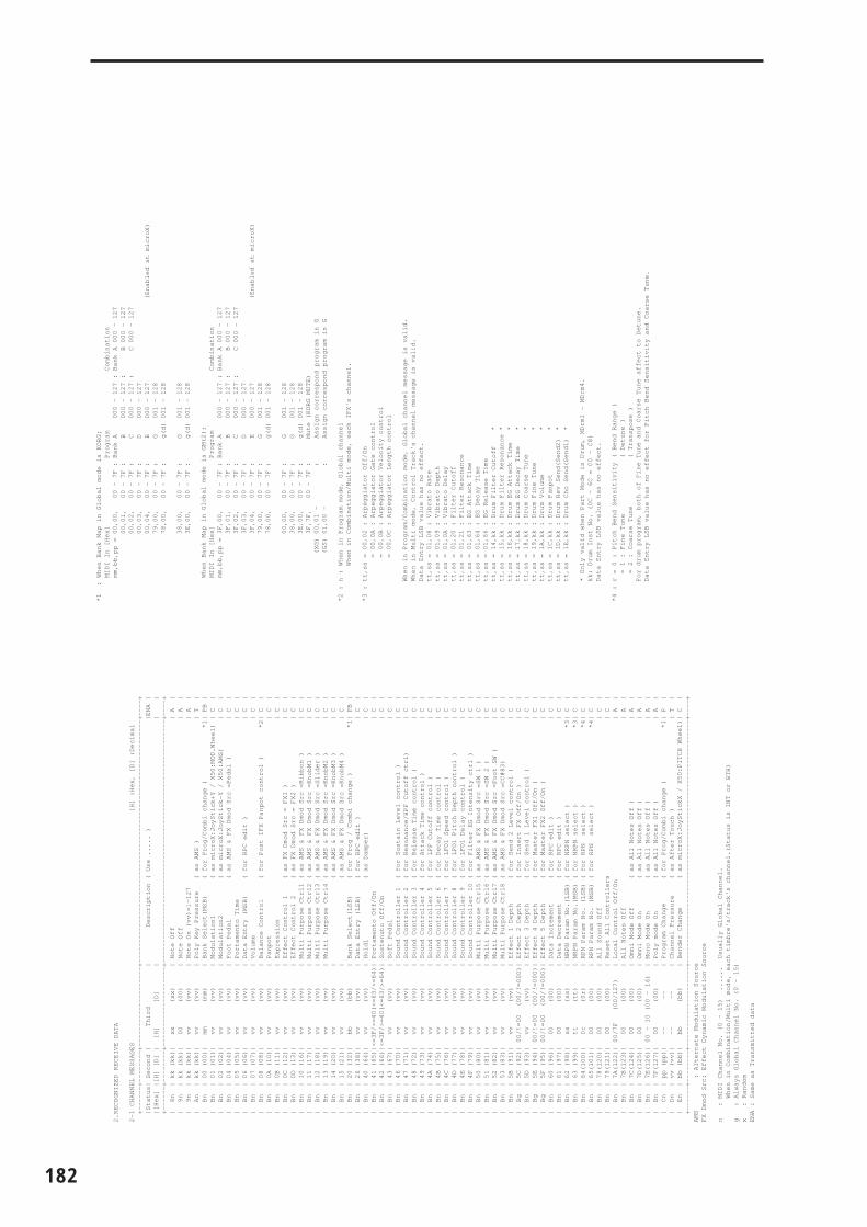
182
2.RECOGNIZED RECEIVE DATA
2-1 CHANNEL MESSAGES [H] :Hex, [D] :Decimal
+------+--------+--------------------+-------------------------------------------------------------+----+
|Status| Second | Third | Description ( Use ..... ) |ENA |
|[Hex] |[H] [D] | [H] [D] | | |
+------+--------+--------------------+-------------------------------------------------------------+----+
| 8n | kk (kk)| xx (xx) | Note Off | A |
| 9n | kk (kk)| 00 (00) | Note Off | A |
| 9n | kk (kk)| vv (vv) | Note On (vv)=1-127 | A |
| An | kk (kk)| vv (vv) | Poly Key Pressure ( as AMS ) | T |
| Bn | 00 (00)| mm (mm) | Bank Select(MSB) ( for Prog/Combi change ) *1| PB |
| Bn | 01 (01)| vv (vv) | Modulation1 ( as microX:JoyStick+Y / X50:MOD.Wheel) | C |
| Bn | 02 (02)| vv (vv) | Modulation2 ( as microX:JoyStick-Y / X50:AMS) | C |
| Bn | 04 (04)| vv (vv) | Foot Pedal ( as AMS & FX Dmod Src =Pedal ) | C |
| Bn | 05 (05)| vv (vv) | Portamento Time | C |
| Bn | 06 (06)| vv (vv) | Data Entry (MSB) ( for RPC edit ) | C |
| Bn | 07 (07)| vv (vv) | Volume | C |
| Bn | 08 (08)| vv (vv) | Balance Control ( for Post IFX Panpot control ) *2| C |
| Bn | 0A (10)| vv (vv) | Panpot | C |
| Bn | 0B (11)| vv (vv) | Expression | C |
| Bn | 0C (12)| vv (vv) | Effect Control 1 ( as FX Dmod Src = FX1 ) | C |
| Bn | 0D (13)| vv (vv) | Effect Control 2 ( as FX Dmod Src = FX2 ) | C |
| Bn | 10 (16)| vv (vv) | Multi Purpose Ctrl1 ( as AMS & FX Dmod Src =Ribbon ) | C |
| Bn | 11 (17)| vv (vv) | Multi Purpose Ctrl2 ( as AMS & FX Dmod Src =KnobM1 ) | C |
| Bn | 12 (18)| vv (vv) | Multi Purpose Ctrl3 ( as AMS & FX Dmod Src =Slider ) | C |
| Bn | 13 (19)| vv (vv) | Multi Purpose Ctrl4 ( as AMS & FX Dmod Src =KnobM2 ) | C |
| Bn | 14 (20)| vv (vv) | ( as AMS & FX Dmod Src =KnobM3 ) | C |
| Bn | 15 (21)| vv (vv) | ( as AMS & FX Dmod Src =KnobM4 ) | C |
| Bn | 20 (32)| bb (bb) | Bank Select(LSB) ( for Prog / Combi change ) *1| PB |
| Bn | 26 (38)| vv (vv) | Data Entry (LSB) ( for RPC edit ) | C |
| Bn | 40 (64)| vv (vv) | Hold1 ( as Damper) | C |
| Bn | 41 (65)|<=3F/>=40(<=63/>=64)| Portamento Off/On | C |
| Bn | 42 (66)|<=3F/>=40(<=63/>=64)| Sostenuto Off/On | C |
| Bn | 43 (67)| vv (vv) | Soft Pedal | C |
| Bn | 46 (70)| vv (vv) | Sound Controller 1 ( for Sustain Level control ) | C |
| Bn | 47 (71)| vv (vv) | Sound Controller 2 ( for Resonance/HPF Cutoff ctrl) | C |
| Bn | 48 (72)| vv (vv) | Sound Controller 3 ( for Release Time control ) | C |
| Bn | 49 (73)| vv (vv) | Sound Controller 4 ( for Attack Time control ) | C |
| Bn | 4A (74)| vv (vv) | Sound Controller 5 ( for LPF Cutoff control ) | C |
| Bn | 4B (75)| vv (vv) | Sound Controller 6 ( for Decay Time control ) | C |
| Bn | 4C (76)| vv (vv) | Sound Controller 7 ( for LFO1 Speed control ) | C |
| Bn | 4D (77)| vv (vv) | Sound Controller 8 ( for LFO1 Pitch Depth control ) | C |
| Bn | 4E (78)| vv (vv) | Sound Controller 9 ( for LFO1 Delay control ) | C |
| Bn | 4F (79)| vv (vv) | Sound Controller 10 ( for Filter EG Intensity ctrl ) | C |
| Bn | 50 (80)| vv (vv) | Multi Purpose Ctrl5 ( as AMS & FX Dmod Src =SW 1 ) | C |
| Bn | 51 (81)| vv (vv) | Multi Purpose Ctrl6 ( as AMS & FX Dmod Src =SW 2 ) | C |
| Bn | 52 (82)| vv (vv) | Multi Purpose Ctrl7 ( as AMS & FX Dmod Src =Foot SW ) | C |
| Bn | 53 (83)| vv (vv) | Multi Purpose Ctrl8 ( as AMS & FX Dmod Src =CC#83) | C |
| Bn | 5B (91)| vv (vv) | Effect 1 Depth ( for Send 2 Level control ) | C |
| Bg | 5C (92)| 00/!=00 (00/!=000)| Effect 2 Depth ( for Insert FX Off/On ) | C |
| Bn | 5D (93)| vv (vv) | Effect 3 Depth ( for Send 1 Level control ) | C |
| Bg | 5E (94)| 00/!=00 (00/!=000)| Effect 4 Depth ( for Master FX1 Off/On ) | C |
| Bg | 5F (95)| 00/!=00 (00/!=000)| Effect 5 Depth ( for Master FX2 Off/On ) | C |
| Bn | 60 (96)| 00 (00) | Data Increment ( for RPC edit ) | C |
| Bn | 61 (97)| 00 (00) | Data Decrement ( for RPC edit ) | C |
| Bn | 62 (98)| ss (ss) | NRPN Param No.(LSB) ( for NRPN select ) *3| C |
| Bn | 63 (99)| tt (tt) | NRPN Param No.(MSB) ( for NRPN select ) *3| C |
| Bn | 64(100)| 0r (0r) | RPN Param No. (LSB) ( for RPN select ) *4| C |
| Bn | 65(101)| 00 (00) | RPN Param No. (MSB) ( for RPN select ) *4| C |
| Bn | 78(120)| 00 (00) | All Sound Off | C |
| Bn | 79(121)| 00 (00) | Reset All Controllers | C |
| Bn | 7A(122)| 00/7F (00/127) | Local Control Off/On | A |
| Bn | 7B(123)| 00 (00) | All Notes Off | A |
| Bn | 7C(124)| 00 (00) | Omni Mode Off ( as All Notes Off ) | A |
| Bn | 7D(125)| 00 (00) | Omni Mode On ( as All Notes Off ) | A |
| Bn | 7E(126)| 00 - 10 (00 - 16) | Mono Mode On ( as All Notes Off ) | A |
| Bn | 7F(127)| 00 (00) | Poly mode On ( as All Notes Off ) | A |
| Cn | pp (pp)| -- -- | Program Change ( for Prog/Combi change ) *1| P |
| Dn | vv (vv)| -- -- | Channel Pressure ( as After Touch ) | T |
| En | bb (bb)| bb (bb) | Bender Change ( as microX:JoyStickX / X50:PITCH Wheel)| C |
+------+--------+--------------------+-------------------------------------------------------------+----+
AMS : Alternate Modulation Source
FX Dmod Src: Effect Dynamic Modulation Source
n : MIDI Channel No. (0 - 15) ...... Usually Global Channel.
When in Combination/Multi mode, each timbre's/track's channel.(Status is INT or BTH)
g : Always Global Channel No. (0 - 15)
x : Random
ENA : Same as Transmitted data
*1 : When Bank Map in Global mode is KORG;
MIDI In [Hex] Program Combination
mm,bb,pp = 00,00, 00 - 7F : Bank A 000 - 127 : Bank A 000 - 127
00,01, 00 - 7F : B 000 - 127 : B 000 - 127
00,02, 00 - 7F : C 000 - 127 : C 000 - 127
00,03, 00 - 7F : D 000 - 127
00,04, 00 - 7F : E 000 - 127 (Enabled at microX)
79,00, 00 - 7F : G 001 - 128
78,00, 00 - 7F : g(d) 001 - 128
38,00, 00 - 7F : G 001 - 128
3E,00, 00 - 7F : g(d) 001 - 128
When Bank Map in Global mode is GM(2);
MIDI In [Hex] Program Combination
mm,bb,pp = 3F,00, 00 - 7F : Bank A 000 - 127 : Bank A 000 - 127
3F,01, 00 - 7F : B 000 - 127 : B 000 - 127
3F,02, 00 - 7F : C 000 - 127 : C 000 - 127
3F,03, 00 - 7F : D 000 - 127
3F,04, 00 - 7F : E 000 - 127 (Enabled at microX)
79,00, 00 - 7F : G 001 - 128
78,00, 00 - 7F : g(d) 001 - 128
00,00, 00 - 7F : G 001 - 128
38,00, 00 - 7F : G 001 - 128
3E,00, 00 - 7F : g(d) 001 - 128
3F,7F, 00 - 7F : Mute (KORG MUTE)
(XG) 00,01 - : Assign correspond program in G
(GS) 01,00 - : Assign correspond program in G
*2 : n : When in Program mode, Global channel
When in Combination/Multi mode, each IFX's channel.
*3 : tt,ss = 00,02 : Arpeggiator Off/On
= 00,0A : Arpeggiator Gate control
= 00,0B : Arpeggiator Velocity control
= 00,0C : Arpeggiator Length control
When in Program/Combination mode, Global channel message is valid.
When in Multi mode, Control Track's channel message is valid.
Data Entry LSB value has no effect.
tt,ss = 01,08 : Vibrato Rate
tt,ss = 01,09 : Vibrato Depth
tt,ss = 01,0A : Vibrato Delay
tt,ss = 01,20 : Filter Cutoff
tt,ss = 01,21 : Filter Resonance
tt,ss = 01,63 : EG Attack Time
tt,ss = 01,64 : EG Decay Time
tt,ss = 01,66 : EG Release Time
tt,ss = 14,kk : Drum Filter Cutoff *
tt,ss = 15,kk : Drum Filter Resonance *
tt,ss = 16,kk : Drum EG Attack Time *
tt,ss = 17,kk : Drum EG Decay Time *
tt,ss = 18,kk : Drum Coarse Tune *
tt,ss = 19,kk : Drum Fine Tune *
tt,ss = 1A,kk : Drum Volume *
tt,ss = 1C,kk : Drum Panpot *
tt,ss = 1D,kk : Drum Rev Send(Send2) *
tt,ss = 1E,kk : Drum Cho Send(Send1) *
* Only valid when Part Mode is Drum, MDrm1 - MDrm4.
kk: Drum Inst No. (0C - 6C = C0 - C8)
Data Entry LSB value has no effect.
*4 : r = 0 : Pitch Bend Sensitivity ( Bend Range )
= 1 : Fine Tune ( Detune )
= 2 : Coarse Tune ( Transpose )
For drum program, both of Fine Tune and Coarse Tune affect to Detune.
Data Entry LSB value has no effect for Pitch Bend Sensitivity and Coarse Tune.

Ap
pen
dic
es
2-2 SYSTEM COMMON MESSAGES [H] :Hex, [D] :Decimal
+------+--------+--------------------+-------------------------------------------------------------+
|Status| Second | Third | Description ( Use for ..... ) |
|[Hex] |[H] [D] | [H] [D] | |
+------+--------+--------------------+-------------------------------------------------------------+
| F3 | ss (ss)| | Song Select |
| | | | ss : Multi(0-127) No. |
+------+--------+--------------------+-------------------------------------------------------------+
Receive Song Select when in Multi mode.
2-3 SYSTEM REALTIME MESSAGES
+------------+--------------------------------------------------------------+
|Status[Hex] | Description ( Use for..... ) |
+------------+--------------------------------------------------------------+
| F8 | Timing Clock ( Tempo, AMS. & FX Dmod Src ) *5|
| FA | Start ( Arpeggiator Control ) *5|
| FB | Continue ( Arpeggiator Control ) *5|
| FC | Stop ( Arpeggiator Control ) *5|
| FE | Active Sensing ( MIDI Connect check ) |
+------------+--------------------------------------------------------------+
*5 : Receive when system is operating by external clock.
2-4 SYSTEM EXCLUSIVE
2-4-1 UNIVERSAL SYSTEM EXCLUSIVE MESSAGES ( NON REALTIME )
DEVICE INQUlRY ( When received this message, transmits INQUlRY MESSAGE REPLY )
[ F0,7E,nn,06,01,F7 ] 3rd byte nn : Channel = 0 - F : Global Channel
= 7F : Any Channel
GM System On ( Receive when in Multi mode )
[ F0,7E,nn,09,01,F7 ] 3rd byte nn : Channel = 0 - F : Global Channel
= 7F : Any Channel
2-4-2 UNIVERSAL SYSTEM EXCLUSIVE MESSAGES ( REALTIME )
Master Volume
[ F0,7F,0g,04,01,vv,mm,F7 ] 3rd byte g : Global Channel
6th byte vv : Value(LSB)
7th byte mm : Value(MSB)
mm,vv = 00,00 - 7F,7F : Min - Max
Master Balance
[ F0,7F,0g,04,02,vv,mm,F7 ] 3rd byte g : Global Channel
6th byte vv : Value(LSB)
7th byte mm : Value(MSB)
mm,vv = 00,00:Left, 40,00:Center, 7F,7F:Right
Master Fine Tune ( Control Master Tune(cent) in Global )
[ F0,7F,0g,04,03,vv,mm,F7 ] 3rd byte g : Global Channel
6th byte vv : Value(LSB)
7th byte mm : Value(MSB)
mm,vv = 20,00:-50, 40,00:+00, 60,00:+50
Master Coarse Tune ( Control Transpose (chromatic step) in Global )
[ F0,7F,0g,04,04,vv,mm,F7 ] 3rd byte g : Global Channel
6th byte vv : Value(LSB)
7th byte mm : Value(MSB)
mm,vv = 34,00:-12, 40,00:+00, 4C,00:+12
183

184
Index
Numerics
10’s Hold...................................... 2, 34
A
Alternate Modulation ....... 13, 14, 15, 18, 20, 23, 151, 154, 174, 175
Alternate Modulation Source ..... 151
AmpSetup............................................. 21
Amp EG ........................................... 23
Amp Level ................................... 4, 21
Amp Modulation............................ 22
AMS(Alternate Modulation Source)Amp AMS.................................... 22Filter AMS.................................... 18Filter EG AMS ............................. 18Freq. AMS .................................... 14JS X/PBend as AMS ............. 43, 65Level Mod. AMS............. 13, 20, 23LFO AMS ................... 11, 12, 19, 23Pan AMS ...................................... 21Pitch AMS .................................... 10Pitch EG AMS.............................. 11Resonance AMS .......................... 16Time Mod. AMS.............. 13, 20, 24
Arabic ................................................. 6
Arpeggiator ......... 5, 25, 37, 47, 69, 89Arpeggiator Run............. 37, 47, 69Arpeggio Type ............................ 90Auto Arpeggiator ....................... 76Control ....................................... 176Pattern .................................... 25, 90Setup................................. 25, 47, 69
Arpeggio pattern ...................... 25, 90
Assign............................. 27, 47, 50, 86Arpeggiator ........................... 47, 69Foot Pedal .................................... 80Foot Switch .................................. 80REALTIME CONTROLS Knob B .
27, 50, 71SW1, SW2......................... 27, 50, 71
Attack Level ........................ 12, 19, 23Amp EG ....................................... 23Filter EG ....................................... 19Pitch EG........................................ 12
Attack Time .............. 4, 12, 19, 23, 87, 156, 175Amp EG........................................ 23Filter EG........................................ 19Pitch EG........................................ 12
AUDITION ........................................ 9
Audition Riff...................................... 9
B
Bank ................. 1, 7, 33, 35, 77, 78, 83, 164, 168, 179
Bank (Bank Select) ...................... 1, 33
Bank select ..................................... 172
Bend Range .......................... 10, 41, 62
BPM/MIDI Sync function ..... 97, 160
Break Point Level ...................... 19, 23Amp EG........................................ 23Filter EG........................................ 19
BUS Select ......... 28, 29, 30, 50, 72, 89, 98, 99, 100, 101, 103
C
Cat. HOLD (Category Hold) ..... 2, 34
Category ............ 2, 3, 9, 34, 36, 58, 86, 87, 88
Category name setup ..................... 86
Chain................................... 30, 72, 102
Combination category.................... 34
Combination mode......................... 33
Combination Select................. 33, 172
Contrast ............................................ 79
Control change .......... 76, 78, 168, 172
Control ChannelInsertFX .................................. 51, 73MasterEQ................................ 53, 74MasterFX ................................ 52, 73
Control Track................................... 56
Convert Position ................. 75, 76, 82
Copy.................................................... 7Copy Arpeggiator ................. 26, 48Copy Drum Kit............................ 88Copy From Combi ...................... 56Copy Insert Effect.................. 28, 72Copy Key Setup........................... 88Copy Master Effect ......... 30, 53, 74Copy Oscillator.............................. 7Copy Scale.................................... 85
Cutoff.................. 38, 87, 155, 162, 163
Cutoff frequency........................16, 87
D
Data Dump.....................................177
Decay Time.......................4, 12, 19, 23Amp EG ........................................23Filter EG ........................................19Pitch EG ........................................12
Demo Song .......................................95
Drum kit ............6, 8, 9, 50, 51, 75, 77, 79, 83, 86, 88, 177Create ............................................86
Drum program.......6, 8, 50, 51, 73, 89
Drums ...........................4, 6, 16, 21, 28
Drumsample ....................................87
Dump ........................................83, 177
Dynamic modulation.........29, 31, 42, 51, 52, 72, 73, 74, 97, 100, 157, 158, 166, 171, 174, 175
E
Effect control ..................................173
EGAmp EG ........................................23Filter EG ........................................19Pitch EG ........................................12
Equal Temperament..........................6
External Control ..............5, 37, 59, 93
External control set ...............5, 37, 59
External MIDI clock ......152, 159, 160
F
Filter ..................................................16
Filter EG............................................18
Filter LFO Modulation....................18
Filter Modulation ......................17, 18
Foot Pedal Assign..........................165
Foot Switch Assign........................164
Foot Switch Polarity........................80
Frequency Modulation ...................14
G
GainMEQ...............................30, 102, 149
Gate time ..........................................26

Ap
pen
dic
es
Global MIDI channel......... 21, 28, 29, 30, 31, 35, 36, 40, 41, 52, 53, 74, 75, 81, 82, 84, 158, 166, 169, 170, 171, 173, 174, 177
Global mode .................................... 75
GM Initialize.................................... 57
GM System On message .............. 179
GS.............................................. 78, 179
H
Half Damper Calibration............... 77
High pass filter........... 16, 21, 44, 162, 163, 168, 169, 175
I
Insert Effect............. 28, 36, 50, 51, 72, 158, 173Setup ................................. 29, 51, 72
K
Key.................................................... 87
Keyboard........................ 26, 37, 48, 90
Keyboard Track........ 17, 22, 152, 154, 155, 156, 157
Key Split........................................... 45
Key Transpose................................. 75
Key Zone.................................... 45, 67
Kirnberger (Kirnberger III).............. 6
L
Layer........................................... 45, 46
LCD Contrast .................................. 79
Legato........................................... 6, 11
LevelAmp EG........................................ 23Amp Level ............................... 4, 21Attack Level................................. 19Filter EG ....................................... 19Level (Chain Level)............... 30, 52Multisample................................... 8OSC Bal (OSC Balance) ................ 4Pitch EG........................................ 12Rtn 1, 2 (Return 1, 2) ............. 30, 52Send .................................. 28, 51, 89Volume ......................................... 58
Level Modulation ............... 13, 20, 23
LFO................................................6, 14OSC..........................................11, 14Pitch...............................................12
LFO Modulation..............................18
LFO setup.........................................14
LFO waveform.................................14
Load Preload Data ..........................77
Local Control ...................................82
Local Control On.............................82
Low pass filter ............16, 21, 44, 163, 168, 175
M
Master Effect ..............4, 30, 52, 73, 74Setup..................................30, 52, 73
Master EQ.....................31, 53, 74, 149Master EQ Gain[dB]............30, 102
Master Fine Tuning message.........75
Master Tune .....................................75
Memory Protect...............................79
MIDI Channel ...........1, 35, 37, 40, 51, 52, 62, 81, 171
MIDI Clock...........................34, 81, 90
MIDI Filter............4, 42, 44, 64, 65, 82Setup..................................16, 42, 64
MIDI RPN coarse tune message ...75
MIDI RPN fine tune message........76
MIDI universal system exclusive message.........................................75
Modulation ...........154, 155, 156, 160, 161, 172
Monophonic.......................................6
Multi mode.......................................55
Multisample...................6, 7, 8, 41, 86
Multi set select .................................55
O
Octave .....................4, 8, 26, 41, 76, 90Adjustment.....................................4
OscillatorSetup................................................6
OSC LFO...........................................14
P
PAGE MENU .................. 1, 33, 55, 75
Pan .... 21, 22, 28, 29, 36, 38, 51, 58, 89
PatternArpeggio pattern .......... 47, 89, 177
Pelog ................................................... 6
Performance Editor .......................... 3
Pitch...................... 7, 10, 11, 12, 14, 41
Pitch bend .......................... 41, 62, 172
Pitch bend change ........................ 172
Pitch EG ........................................... 12
Pitch LFO Modulation ................... 11
Pitch modulation ........ 10, 11, 12, 154
Polyphonic/Monophonic.......... 6, 40
Portamento ................... 11, 40, 62, 64, 161, 164, 165, 168, 173
Portamento time ............................. 11
Positional Cross-fade ..................... 45
Program bank.................................... 1
Program category ............................. 2
Program Change........................... 171MIDI Filter ................................... 64
Program change message...... 42, 164
Program mode .................................. 1
Program Select ................ 2, 35, 38, 57
Pure Major ......................................... 6
Pure Minor......................................... 6
Pythagoras ......................................... 6
R
REALTIME CONTROLS ........ 25, 27, 34, 44, 50, 65, 90, 149, 153, 157, 162, 163, 166, 168, 172, 173, 174, 176, 178
Release Level ............................. 12, 19Pitch EG........................................ 12
Release Time........................ 12, 20, 23Amp EG........................................ 23Filter EG ................................. 19, 20Pitch EG........................................ 12
Resolution........................................ 26
Resonance ........... 17, 44, 87, 155, 162, 163, 168, 169, 175
Return level ..................................... 30
Rhythm loop.................................... 41
Routing................... 29, 51, 73, 98, 101
RPN ................................................ 175
185
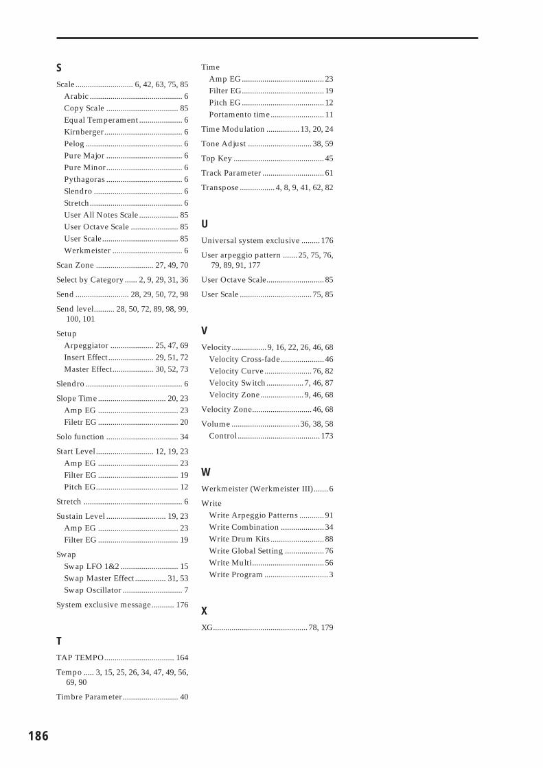
186
S
Scale............................ 6, 42, 63, 75, 85Arabic ............................................. 6Copy Scale ................................... 85Equal Temperament..................... 6Kirnberger...................................... 6Pelog ............................................... 6Pure Major ..................................... 6Pure Minor..................................... 6Pythagoras ..................................... 6Slendro ........................................... 6Stretch............................................. 6User All Notes Scale................... 85User Octave Scale ....................... 85User Scale..................................... 85Werkmeister .................................. 6
Scan Zone ............................ 27, 49, 70
Select by Category...... 2, 9, 29, 31, 36
Send .......................... 28, 29, 50, 72, 98
Send level.......... 28, 50, 72, 89, 98, 99, 100, 101
SetupArpeggiator ..................... 25, 47, 69Insert Effect...................... 29, 51, 72Master Effect.................... 30, 52, 73
Slendro ............................................... 6
Slope Time................................. 20, 23Amp EG ....................................... 23Filetr EG ....................................... 20
Solo function ................................... 34
Start Level............................ 12, 19, 23Amp EG ....................................... 23Filter EG ....................................... 19Pitch EG........................................ 12
Stretch ................................................ 6
Sustain Level ............................. 19, 23Amp EG ....................................... 23Filter EG ....................................... 19
SwapSwap LFO 1&2 ............................ 15Swap Master Effect............... 31, 53Swap Oscillator ............................. 7
System exclusive message........... 176
T
TAP TEMPO.................................. 164
Tempo ..... 3, 15, 25, 26, 34, 47, 49, 56, 69, 90
Timbre Parameter........................... 40
TimeAmp EG........................................ 23Filter EG........................................ 19Pitch EG........................................ 12Portamento time.......................... 11
Time Modulation ................ 13, 20, 24
Tone Adjust ............................... 38, 59
Top Key ............................................ 45
Track Parameter .............................. 61
Transpose ................. 4, 8, 9, 41, 62, 82
U
Universal system exclusive ......... 176
User arpeggio pattern ....... 25, 75, 76, 79, 89, 91, 177
User Octave Scale............................ 85
User Scale ................................... 75, 85
V
Velocity................. 9, 16, 22, 26, 46, 68Velocity Cross-fade..................... 46Velocity Curve....................... 76, 82Velocity Switch.................. 7, 46, 87Velocity Zone..................... 9, 46, 68
Velocity Zone............................. 46, 68
Volume ................................. 36, 38, 58Control........................................ 173
W
Werkmeister (Werkmeister III) ....... 6
WriteWrite Arpeggio Patterns ............ 91Write Combination ..................... 34Write Drum Kits.......................... 88Write Global Setting ................... 76Write Multi................................... 56Write Program............................... 3
X
XG.............................................. 78, 179

2005 KORG INC.
This product has been manufactured according to strict specifications and voltage requirements that are applicable in the country in which it is intended that this product should be used. If you have purchased this product via the internet, through mail order, and/or via a telephone sale, you must verify that this product is intended to be used in the country in which you reside.WARNING: Use of this product in any country other than that for which it is intended could be dangerous and could invalidate the manufacturer’s or distributor’s warranty.Please also retain your receipt as proof of purchase otherwise your product may be disqualified from the manufacturer’s or distributor’s warranty.
IMPORTANT NOTICE TO CONSUMERS
4015-2 Yanokuchi, Inagi-city, Tokyo 206-0812 Japan