Embed Size (px)
Citation preview
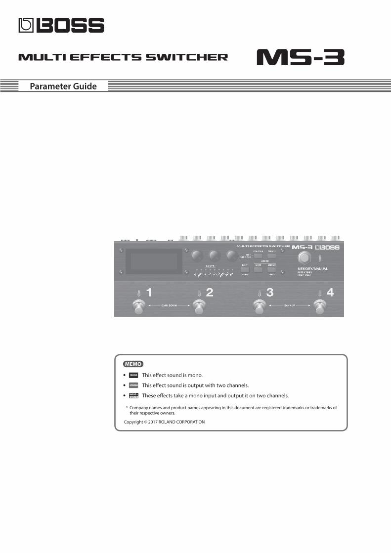
Parameter Guide
MEMO
5 This effect sound is mono.
5 This effect sound is output with two channels.
5 These effects take a mono input and output it on two channels.
* Company names and product names appearing in this document are registered trademarks or trademarks of their respective owners.
Copyright © 2017 ROLAND CORPORATION
2
ContentsBasic Operation 3
Basic Procedure for Effect Editing 3
Changing the Effect Connection Order 4
Changing the CTL/ASSIGN/MIDI Settings 4
Saving a Patch (Write) 4
Exchanging Patches 5
Initializing a Patch 5
EFFECT 6
FX1/FX2 6
COMPRESSOR 7
LIMITER 7
T. WAH 8
BASS T. WAH 8
AUTO WAH 8
WAH 8
BASS WAH 9
OD/DS 9
BASS OD/DS 10
GRAPHIC EQ 10
PARAMETRIC EQ 10
AC. GUITAR SIMULATOR 10
DEFRETTER 10
SITAR SIM 11
SLOW GEAR 11
BASS SLOW GEAR 11
OCTAVE 11
BASS OCTAVE 11
PITCH SHIFTER 11
BASS PITCH SHIFTER 12
HARMONIST 12
BASS HARMONIST 13
OVERTONE 13
PEDAL BEND 13
BASS PEDAL BEND 13
SOUND HOLD 13
S-BEND 13
BASS S-BEND 14
WARP 14
FEEDBACKER 14
SUB DELAY 14
MOD1/MOD2 15
CHORUS 15
2X2 CHORUS 16
PHASER 16
FLANGER 17
BASS FLANGER 17
TREMOLO 17
PAN 17
ROTARY 18
UNI-V 18
SLICER 18
VIBRATO 18
RING MOD 19
DLY (DELAY) 19
SINGLE 20
PAN 20
STEREO 20
DUAL-S (DUAL-SERIES) 20
DUAL-P (DUAL-PARALLE) 21
DUAL-L/R 21
REVERSE 21
ANALOG 21
TAPE (TAPE ECHO) 22
MODULATE 22
TERA ECHO 22
REV (REVERB) 23
AMBIENCE 23
ROOM 23
HALL1 23
HALL2 24
PLATE 24
SPRING 24
MODULATE 24
DELAY 24
L1 (LOOP 1) 25
L2 (LOOP 2) 25
L3 (LOOP 3) 25
NS (NOISE SUPPRESSOR) 25
FV (FOOT VOLUME) 26
MST (MASTER SETTING) 26
PATCH LVL (PATCH LEVEL) 26
OUTPUT (OUTPUT SETTING) 27
CTL (CTL,ASSIGN&MIDI SETTING) 28
NUM1–4 (NUMBER SW1–4) 28
MEMORY MANUAL (MEMORY/MANUAL SW) 29
CURRENT NUMBER (CURRENT NUMBER SW) 30
EXP 1, EXP 2 31
CTL IN1–4 31
ASSIGN 1–8 32
Virtual Expression Pedal System (Internal Pedal/Wave Pedal) 38
PATCH MIDI 1–4 39
MENU 40
DISPLAY 40
GLOBAL (GLOBAL EQ) 40
PLAY (PLAY OPTION) 40
CTLOUT (CTL OUT MODE SETTING) 40
KNOB (KNOB SETTING) 41
MIDI (MIDI SETTING) 41
PREF (PREFERENCE) 41
AUTO OFF 42
F.RESET (FACTORY RESET) 42
Other Settings 43
TUNER 43
Patch List 44
3
Basic Operation
Basic Procedure for Effect Editing
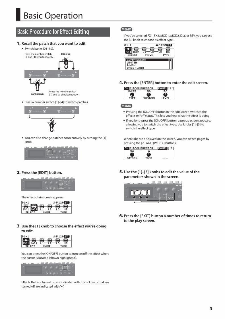
1 Recall the patch that you want to edit. 5 Switch banks (01–50).
Bank down
Bank up
Press the number switch [1] and [2] simultaneously.
Press the number switch [3] and [4] simultaneously.
5 Press a number switch [1]–[4] to switch patches.
5 You can also change patches consecutively by turning the [1] knob.
2 Press the [EDIT] button.
The effect chain screen appears.
3 Use the [1] knob to choose the effect you’re going to edit.
You can press the [ON/OFF] button to turn on/off the effect where the cursor is located (shown highlighted).
Effects that are turned on are indicated with icons. Effects that are turned off are indicated with “5.”
MEMO
If you’ve selected FX1, FX2, MOD1, MOD2, DLY, or REV, you can use the [3] knob to choose its effect type.
4 Press the [ENTER] button to enter the edit screen.
MEMO
5 Pressing the [ON/OFF] button in the edit screen switches the effect’s on/off status. This lets you hear what the effect is doing.
5 If you long-press the [ON/OFF] button, a popup screen appears, allowing you to switch the effect type. Use knobs [1]–[3] to switch the effect type.
When tabs are displayed on the screen, you can switch pages by pressing the [< PAGE] [PAGE >] buttons.
5 Use the [1]–[3] knobs to edit the value of the parameters shown in the screen.
6 Press the [EXIT] button a number of times to return to the play screen.
4
Basic Operation
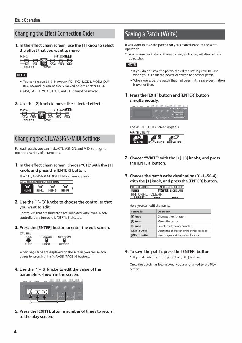
Changing the Effect Connection Order
1 In the effect chain screen, use the [1] knob to select the effect that you want to move.
NOTE
5 You can’t move L1–3. However, FX1, FX2, MOD1, MOD2, DLY, REV, NS, and FV can be freely moved before or after L1–3.
5 MST, PATCH LVL, OUTPUT, and CTL cannot be moved.
2 Use the [2] knob to move the selected effect.
Changing the CTL/ASSIGN/MIDI SettingsFor each patch, you can make CTL, ASSIGN, and MIDI settings to operate a variety of parameters.
1 In the effect chain screen, choose “CTL” with the [1] knob, and press the [ENTER] button.The CTL, ASSIGN & MIDI SETTING screen appears.
2 Use the [1]–[3] knobs to choose the controller that you want to edit.Controllers that are turned on are indicated with icons. When controllers are turned off, “OFF” is indicated.
3 Press the [ENTER] button to enter the edit screen.
When page tabs are displayed on the screen, you can switch pages by pressing the [< PAGE] [PAGE >] buttons.
4 Use the [1]–[3] knobs to edit the value of the parameters shown in the screen.
5 Press the [EXIT] button a number of times to return to the play screen.
Saving a Patch (Write)If you want to save the patch that you created, execute the Write operation.* You can use dedicated software to save, exchange, initialize, or back
up patches.
NOTE
5 If you do not save the patch, the edited settings will be lost when you turn off the power or switch to another patch.
5 When you save, the patch that had been in the save-destination is overwritten.
1 Press the [EXIT] button and [ENTER] button simultaneously.
The WRITE UTILITY screen appears.
2 Choose “WRITE” with the [1]–[3] knobs, and press the [ENTER] button.
3 Choose the patch write destination (01-1–50-4) with the [1] knob, and press the [ENTER] button.
Here you can edit the name.
Controller Operation
[1] knob Changes the character
[2] knob Moves the cursor
[3] knob Selects the type of characters
[EDIT] button Delete the character at the cursor location
[MENU] button Insert a space at the cursor location
4 To save the patch, press the [ENTER] button.* If you decide to cancel, press the [EXIT] button.
Once the patch has been saved, you are returned to the Play screen.
5
Basic Operation
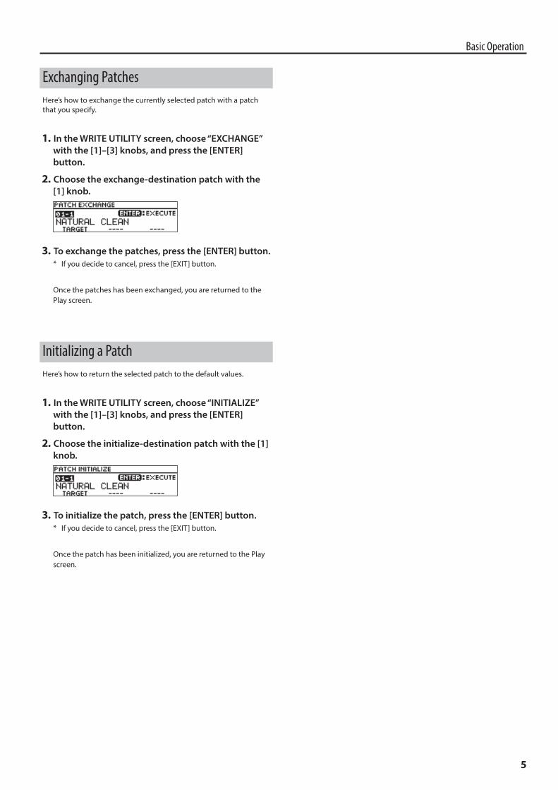
Exchanging PatchesHere’s how to exchange the currently selected patch with a patch that you specify.
1 In the WRITE UTILITY screen, choose “EXCHANGE” with the [1]–[3] knobs, and press the [ENTER] button.
2 Choose the exchange-destination patch with the [1] knob.
3 To exchange the patches, press the [ENTER] button.* If you decide to cancel, press the [EXIT] button.
Once the patches has been exchanged, you are returned to the Play screen.
Initializing a PatchHere’s how to return the selected patch to the default values.
1 In the WRITE UTILITY screen, choose “INITIALIZE” with the [1]–[3] knobs, and press the [ENTER] button.
2 Choose the initialize-destination patch with the [1] knob.
3 To initialize the patch, press the [ENTER] button.* If you decide to cancel, press the [EXIT] button.
Once the patch has been initialized, you are returned to the Play screen.
6
EFFECT
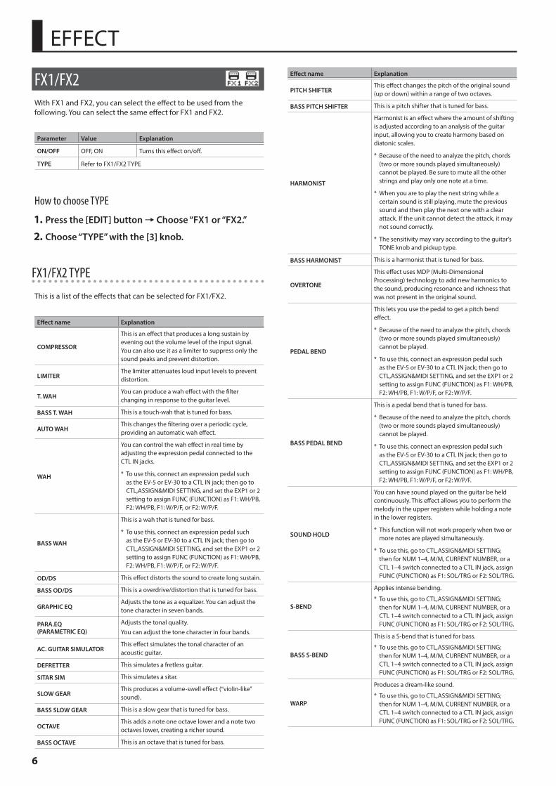
FX1/FX2With FX1 and FX2, you can select the effect to be used from the following. You can select the same effect for FX1 and FX2.
Parameter Value Explanation
ON/OFF OFF, ON Turns this effect on/off.
TYPE Refer to FX1/FX2 TYPE
How to choose TYPE
1 Press the [EDIT] button0Choose “FX1 or “FX2.”
2 Choose “TYPE” with the [3] knob.
FX1/FX2 TYPE
This is a list of the effects that can be selected for FX1/FX2.
Effect name Explanation
COMPRESSOR
This is an effect that produces a long sustain by evening out the volume level of the input signal. You can also use it as a limiter to suppress only the sound peaks and prevent distortion.
LIMITERThe limiter attenuates loud input levels to prevent distortion.
T. WAHYou can produce a wah effect with the filter changing in response to the guitar level.
BASS T. WAH This is a touch-wah that is tuned for bass.
AUTO WAHThis changes the filtering over a periodic cycle, providing an automatic wah effect.
WAH
You can control the wah effect in real time by adjusting the expression pedal connected to the CTL IN jacks.
* To use this, connect an expression pedal such as the EV-5 or EV-30 to a CTL IN jack; then go to CTL,ASSIGN&MIDI SETTING, and set the EXP1 or 2 setting to assign FUNC (FUNCTION) as F1: WH/PB, F2: WH/PB, F1: W/P/F, or F2: W/P/F.
BASS WAH
This is a wah that is tuned for bass.
* To use this, connect an expression pedal such as the EV-5 or EV-30 to a CTL IN jack; then go to CTL,ASSIGN&MIDI SETTING, and set the EXP1 or 2 setting to assign FUNC (FUNCTION) as F1: WH/PB, F2: WH/PB, F1: W/P/F, or F2: W/P/F.
OD/DS This effect distorts the sound to create long sustain.
BASS OD/DS This is a overdrive/distortion that is tuned for bass.
GRAPHIC EQAdjusts the tone as a equalizer. You can adjust the tone character in seven bands.
PARA.EQ (PARAMETRIC EQ)
Adjusts the tonal quality. You can adjust the tone character in four bands.
AC. GUITAR SIMULATORThis effect simulates the tonal character of an acoustic guitar.
DEFRETTER This simulates a fretless guitar.
SITAR SIM This simulates a sitar.
SLOW GEARThis produces a volume-swell effect (“violin-like” sound).
BASS SLOW GEAR This is a slow gear that is tuned for bass.
OCTAVEThis adds a note one octave lower and a note two octaves lower, creating a richer sound.
BASS OCTAVE This is an octave that is tuned for bass.
Effect name Explanation
PITCH SHIFTERThis effect changes the pitch of the original sound (up or down) within a range of two octaves.
BASS PITCH SHIFTER This is a pitch shifter that is tuned for bass.
HARMONIST
Harmonist is an effect where the amount of shifting is adjusted according to an analysis of the guitar input, allowing you to create harmony based on diatonic scales.
* Because of the need to analyze the pitch, chords (two or more sounds played simultaneously) cannot be played. Be sure to mute all the other strings and play only one note at a time.
* When you are to play the next string while a certain sound is still playing, mute the previous sound and then play the next one with a clear attack. If the unit cannot detect the attack, it may not sound correctly.
* The sensitivity may vary according to the guitar’s TONE knob and pickup type.
BASS HARMONIST This is a harmonist that is tuned for bass.
OVERTONE
This effect uses MDP (Multi-Dimensional Processing) technology to add new harmonics to the sound, producing resonance and richness that was not present in the original sound.
PEDAL BEND
This lets you use the pedal to get a pitch bend effect.
* Because of the need to analyze the pitch, chords (two or more sounds played simultaneously) cannot be played.
* To use this, connect an expression pedal such as the EV-5 or EV-30 to a CTL IN jack; then go to CTL,ASSIGN&MIDI SETTING, and set the EXP1 or 2 setting to assign FUNC (FUNCTION) as F1: WH/PB, F2: WH/PB, F1: W/P/F, or F2: W/P/F.
BASS PEDAL BEND
This is a pedal bend that is tuned for bass.
* Because of the need to analyze the pitch, chords (two or more sounds played simultaneously) cannot be played.
* To use this, connect an expression pedal such as the EV-5 or EV-30 to a CTL IN jack; then go to CTL,ASSIGN&MIDI SETTING, and set the EXP1 or 2 setting to assign FUNC (FUNCTION) as F1: WH/PB, F2: WH/PB, F1: W/P/F, or F2: W/P/F.
SOUND HOLD
You can have sound played on the guitar be held continuously. This effect allows you to perform the melody in the upper registers while holding a note in the lower registers.
* This function will not work properly when two or more notes are played simultaneously.
* To use this, go to CTL,ASSIGN&MIDI SETTING; then for NUM 1–4, M/M, CURRENT NUMBER, or a CTL 1–4 switch connected to a CTL IN jack, assign FUNC (FUNCTION) as F1: SOL/TRG or F2: SOL/TRG.
S-BEND
Applies intense bending.
* To use this, go to CTL,ASSIGN&MIDI SETTING; then for NUM 1–4, M/M, CURRENT NUMBER, or a CTL 1–4 switch connected to a CTL IN jack, assign FUNC (FUNCTION) as F1: SOL/TRG or F2: SOL/TRG.
BASS S-BEND
This is a S-bend that is tuned for bass.
* To use this, go to CTL,ASSIGN&MIDI SETTING; then for NUM 1–4, M/M, CURRENT NUMBER, or a CTL 1–4 switch connected to a CTL IN jack, assign FUNC (FUNCTION) as F1: SOL/TRG or F2: SOL/TRG.
WARP
Produces a dream-like sound.
* To use this, go to CTL,ASSIGN&MIDI SETTING; then for NUM 1–4, M/M, CURRENT NUMBER, or a CTL 1–4 switch connected to a CTL IN jack, assign FUNC (FUNCTION) as F1: SOL/TRG or F2: SOL/TRG.
7
EFFECT
Effect name Explanation
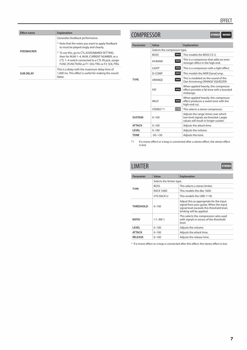
FEEDBACKER
Generates feedback performance.
* Note that the notes you want to apply feedback to must be played singly and cleanly.
* To use this, go to CTL,ASSIGN&MIDI SETTING; then for NUM 1–4, M/M, CURRENT NUMBER, or a CTL 1–4 switch connected to a CTL IN jack, assign FUNC (FUNCTION) as F1: SOL/TRG or F2: SOL/TRG.
SUB DELAYThis is a delay with the maximum delay time of 1,000 ms. This effect is useful for making the sound fatter.
COMPRESSORParameter Value Explanation
TYPE
Selects the compressor type.
BOSS This models the BOSS CS-3.
HI-BAND This is a compressor that adds an even stronger effect in the high end.
LIGHT This is a compressor with a light effect.
D-COMP This models the MXR DynaComp.
ORANGE This is modeled on the sound of the Dan Armstrong ORANGE SQUEEZER.
FATWhen applied heavily, this compressor effect provides a fat tone with a boosted midrange.
MILDWhen applied heavily, this compressor effect produces a sweet tone with the high end cut.
STEREO *1 This selects a stereo compressor.
SUSTAIN 0–100Adjusts the range (time) over which low-level signals are boosted. Larger values will result in longer sustain.
ATTACK 0–100 Adjusts the attack time.
LEVEL 0–100 Adjusts the volume.
TONE -50–+50 Adjusts the tone.
*1 If a mono effect or a loop is connected after a stereo effect, the stereo effect is lost.
LIMITERParameter Value Explanation
TYPE
Selects the limiter type.
BOSS This selects a stereo limiter.
RACK 160D This models the dbx 160X.
VTG RACK U This models the UREI 1178.
THRESHOLD 0–100
Adjust this as appropriate for the input signal from your guitar. When the input signal level exceeds this threshold level, limiting will be applied.
RATIO 1:1–INF:1This selects the compression ratio used with signals in excess of the threshold level.
LEVEL 0–100 Adjusts the volume.
ATTACK 0–100 Adjusts the attack time.
RELEASE 0–100 Adjusts the release time.
* If a mono effect or a loop is connected after this effect, the stereo effect is lost.
8
EFFECT
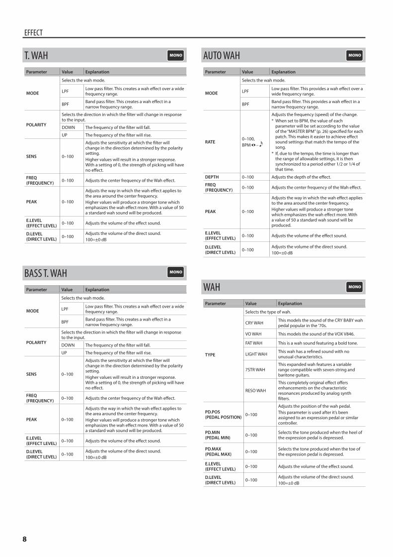
T. WAHParameter Value Explanation
MODE
Selects the wah mode.
LPF Low pass filter. This creates a wah effect over a wide frequency range.
BPF Band pass filter. This creates a wah effect in a narrow frequency range.
POLARITY
Selects the direction in which the filter will change in response to the input.
DOWN The frequency of the filter will fall.
UP The frequency of the filter will rise.
SENS 0–100
Adjusts the sensitivity at which the filter will change in the direction determined by the polarity setting.Higher values will result in a stronger response. With a setting of 0, the strength of picking will have no effect.
FREQ(FREQUENCY) 0–100 Adjusts the center frequency of the Wah effect.
PEAK 0–100
Adjusts the way in which the wah effect applies to the area around the center frequency.Higher values will produce a stronger tone which emphasizes the wah effect more. With a value of 50 a standard wah sound will be produced.
E.LEVEL(EFFECT LEVEL) 0–100 Adjusts the volume of the effect sound.
D.LEVEL(DIRECT LEVEL) 0–100
Adjusts the volume of the direct sound.100=±0 dB
BASS T. WAHParameter Value Explanation
MODE
Selects the wah mode.
LPF Low pass filter. This creates a wah effect over a wide frequency range.
BPF Band pass filter. This creates a wah effect in a narrow frequency range.
POLARITY
Selects the direction in which the filter will change in response to the input.
DOWN The frequency of the filter will fall.
UP The frequency of the filter will rise.
SENS 0–100
Adjusts the sensitivity at which the filter will change in the direction determined by the polarity setting.Higher values will result in a stronger response. With a setting of 0, the strength of picking will have no effect.
FREQ(FREQUENCY) 0–100 Adjusts the center frequency of the Wah effect.
PEAK 0–100
Adjusts the way in which the wah effect applies to the area around the center frequency.Higher values will produce a stronger tone which emphasizes the wah effect more. With a value of 50 a standard wah sound will be produced.
E.LEVEL(EFFECT LEVEL) 0–100 Adjusts the volume of the effect sound.
D.LEVEL(DIRECT LEVEL) 0–100
Adjusts the volume of the direct sound.100=±0 dB
AUTO WAHParameter Value Explanation
MODE
Selects the wah mode.
LPF Low pass filter. This provides a wah effect over a wide frequency range.
BPF Band pass filter. This provides a wah effect in a narrow frequency range.
RATE0–100, BPM –
Adjusts the frequency (speed) of the change.* When set to BPM, the value of each
parameter will be set according to the value of the “MASTER BPM” (p. 26) specified for each patch. This makes it easier to achieve effect sound settings that match the tempo of the song.
* If, due to the tempo, the time is longer than the range of allowable settings, it is then synchronized to a period either 1/2 or 1/4 of that time.
DEPTH 0–100 Adjusts the depth of the effect.
FREQ(FREQUENCY) 0–100 Adjusts the center frequency of the Wah effect.
PEAK 0–100
Adjusts the way in which the wah effect applies to the area around the center frequency.Higher values will produce a stronger tone which emphasizes the wah effect more. With a value of 50 a standard wah sound will be produced.
E.LEVEL(EFFECT LEVEL) 0–100 Adjusts the volume of the effect sound.
D.LEVEL(DIRECT LEVEL) 0–100
Adjusts the volume of the direct sound.100=±0 dB
WAHParameter Value Explanation
TYPE
Selects the type of wah.
CRY WAH This models the sound of the CRY BABY wah pedal popular in the ’70s.
VO WAH This models the sound of the VOX V846.
FAT WAH This is a wah sound featuring a bold tone.
LIGHT WAH This wah has a refined sound with no unusual characteristics.
7STR WAHThis expanded wah features a variable range compatible with seven-string and baritone guitars.
RESO WAH
This completely original effect offers enhancements on the characteristic resonances produced by analog synth filters.
PD.POS (PEDAL POSITION) 0–100
Adjusts the position of the wah pedal.This parameter is used after it’s been assigned to an expression pedal or similar controller.
PD.MIN (PEDAL MIN) 0–100 Selects the tone produced when the heel of
the expression pedal is depressed.
PD.MAX (PEDAL MAX) 0–100 Selects the tone produced when the toe of
the expression pedal is depressed.
E.LEVEL(EFFECT LEVEL) 0–100 Adjusts the volume of the effect sound.
D.LEVEL(DIRECT LEVEL) 0–100
Adjusts the volume of the direct sound.100=±0 dB
9
EFFECT
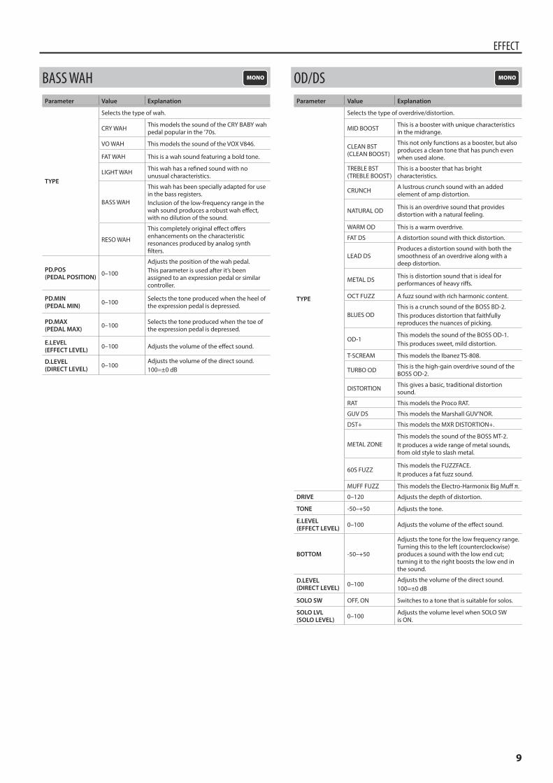
BASS WAHParameter Value Explanation
TYPE
Selects the type of wah.
CRY WAH This models the sound of the CRY BABY wah pedal popular in the ’70s.
VO WAH This models the sound of the VOX V846.
FAT WAH This is a wah sound featuring a bold tone.
LIGHT WAH This wah has a refined sound with no unusual characteristics.
BASS WAH
This wah has been specially adapted for use in the bass registers.Inclusion of the low-frequency range in the wah sound produces a robust wah effect, with no dilution of the sound.
RESO WAH
This completely original effect offers enhancements on the characteristic resonances produced by analog synth filters.
PD.POS (PEDAL POSITION) 0–100
Adjusts the position of the wah pedal.This parameter is used after it’s been assigned to an expression pedal or similar controller.
PD.MIN (PEDAL MIN) 0–100 Selects the tone produced when the heel of
the expression pedal is depressed.
PD.MAX (PEDAL MAX) 0–100 Selects the tone produced when the toe of
the expression pedal is depressed.
E.LEVEL(EFFECT LEVEL) 0–100 Adjusts the volume of the effect sound.
D.LEVEL(DIRECT LEVEL) 0–100
Adjusts the volume of the direct sound.100=±0 dB
OD/DSParameter Value Explanation
TYPE
Selects the type of overdrive/distortion.
MID BOOST This is a booster with unique characteristics in the midrange.
CLEAN BST (CLEAN BOOST)
This not only functions as a booster, but also produces a clean tone that has punch even when used alone.
TREBLE BST (TREBLE BOOST)
This is a booster that has bright characteristics.
CRUNCH A lustrous crunch sound with an added element of amp distortion.
NATURAL OD This is an overdrive sound that provides distortion with a natural feeling.
WARM OD This is a warm overdrive.
FAT DS A distortion sound with thick distortion.
LEAD DSProduces a distortion sound with both the smoothness of an overdrive along with a deep distortion.
METAL DS This is distortion sound that is ideal for performances of heavy riffs.
OCT FUZZ A fuzz sound with rich harmonic content.
BLUES ODThis is a crunch sound of the BOSS BD-2.This produces distortion that faithfully reproduces the nuances of picking.
OD-1This models the sound of the BOSS OD-1.This produces sweet, mild distortion.
T-SCREAM This models the Ibanez TS-808.
TURBO OD This is the high-gain overdrive sound of the BOSS OD-2.
DISTORTION This gives a basic, traditional distortion sound.
RAT This models the Proco RAT.
GUV DS This models the Marshall GUV’NOR.
DST+ This models the MXR DISTORTION+.
METAL ZONEThis models the sound of the BOSS MT-2.It produces a wide range of metal sounds, from old style to slash metal.
60S FUZZThis models the FUZZFACE.It produces a fat fuzz sound.
MUFF FUZZ This models the Electro-Harmonix Big Muff π.
DRIVE 0–120 Adjusts the depth of distortion.
TONE -50–+50 Adjusts the tone.
E.LEVEL(EFFECT LEVEL) 0–100 Adjusts the volume of the effect sound.
BOTTOM -50–+50
Adjusts the tone for the low frequency range. Turning this to the left (counterclockwise) produces a sound with the low end cut; turning it to the right boosts the low end in the sound.
D.LEVEL(DIRECT LEVEL) 0–100
Adjusts the volume of the direct sound.100=±0 dB
SOLO SW OFF, ON Switches to a tone that is suitable for solos.
SOLO LVL (SOLO LEVEL) 0–100 Adjusts the volume level when SOLO SW
is ON.
10
EFFECT
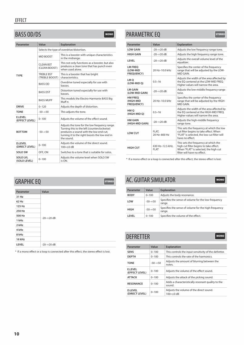
BASS OD/DSParameter Value Explanation
TYPE
Selects the type of overdrive/distortion.
MID BOOST This is a booster with unique characteristics in the midrange.
CLEAN BST (CLEAN BOOST)
This not only functions as a booster, but also produces a clean tone that has punch even when used alone.
TREBLE BST (TREBLE BOOST)
This is a booster that has bright characteristics.
BASS OD Overdrive tuned especially for use with basses.
BASS DST Distortion tuned especially for use with basses.
BASS MUFF This models the Electro-Harmonix BASS Big Muff π.
DRIVE 0–120 Adjusts the depth of distortion.
TONE -50–+50 This adjusts the tone.
E.LEVEL(EFFECT LEVEL) 0–100 Adjusts the volume of the effect sound.
BOTTOM -50–+50
Adjusts the tone for the low frequency range. Turning this to the left (counterclockwise) produces a sound with the low end cut; turning it to the right boosts the low end in the sound.
D.LEVEL(DIRECT LEVEL) 0–100
Adjusts the volume of the direct sound.100=±0 dB
SOLO SW OFF, ON Switches to a tone that is suitable for solos.
SOLO LVL (SOLO LEVEL) 0–100 Adjusts the volume level when SOLO SW
is ON.
GRAPHIC EQParameter Value
31 Hz
-20–+20 dB
62 Hz
125 Hz
250 Hz
500 Hz
1 kHz
2 kHz
4 kHz
8 kHz
16 kHz
LEVEL -20–+20 dB
* If a mono effect or a loop is connected after this effect, the stereo effect is lost.
PARAMETRIC EQParameter Value Explanation
LOW GAIN -20–+20 dB Adjusts the low frequency range tone.
HIGH GAIN -20–+20 dB Adjusts the high frequency range tone.
LEVEL -20–+20 dB Adjusts the overall volume level of the equalizer.
LM FREQ (LOW-MID FREQUENCY)
20 Hz–10.0 kHzSpecifies the center of the frequency range that will be adjusted by the LOW-MID GAIN.
LM Q(LOW-MID Q) 0.5–16
Adjusts the width of the area affected by the EQ centered at the LOW-MID FREQ. Higher values will narrow the area.
LM GAIN(LOW-MID GAIN) -20–+20 dB Adjusts the low-middle frequency range
tone.
HM FREQ(HIGH-MID FREQUENCY)
20 Hz–10.0 kHzSpecifies the center of the frequency range that will be adjusted by the HIGH-MID GAIN.
HM Q (HIGH-MID Q) 0.5–16
Adjusts the width of the area affected by the EQ centered at the HIGH-MID FREQ. Higher values will narrow the area.
HM GAIN(HIGH-MID GAIN) -20–+20 dB Adjusts the high-middle frequency
range tone.
LOW CUT FLAT, 20 Hz–800 Hz
This sets the frequency at which the low cut filter begins to take effect. When “FLAT” is selected, the low cut filter will have no effect.
HIGH CUT 630 Hz–12.5 kHz, FLAT
This sets the frequency at which the high cut filter begins to take effect. When “FLAT” is selected, the high cut filter will have no effect.
* If a mono effect or a loop is connected after this effect, the stereo effect is lost.
AC. GUITAR SIMULATORParameter Value Explanation
BODY 0–100 Adjusts the body resonance.
LOW -50–+50 Specifies the sense of volume for the low-frequency range.
HIGH -50–+50 Specifies the sense of volume for the high-frequency range.
LEVEL 0–100 Specifies the volume of the effect.
DEFRETTERParameter Value Explanation
SENS 0–100 This controls the input sensitivity of the defretter.
DEPTH 0–100 This controls the rate of the harmonics.
TONE -50–+50 Adjusts the amount of blurring between the notes.
E.LEVEL (EFFECT LEVEL) 0–100 Adjusts the volume of the effect sound.
ATTACK 0–100 Adjusts the attack of the picking sound.
RESONANCE 0–100 Adds a characteristically resonant quality to the sound.
D.LEVEL(DIRECT LEVEL) 0–100
Adjusts the volume of the direct sound.100=±0 dB
11
EFFECT
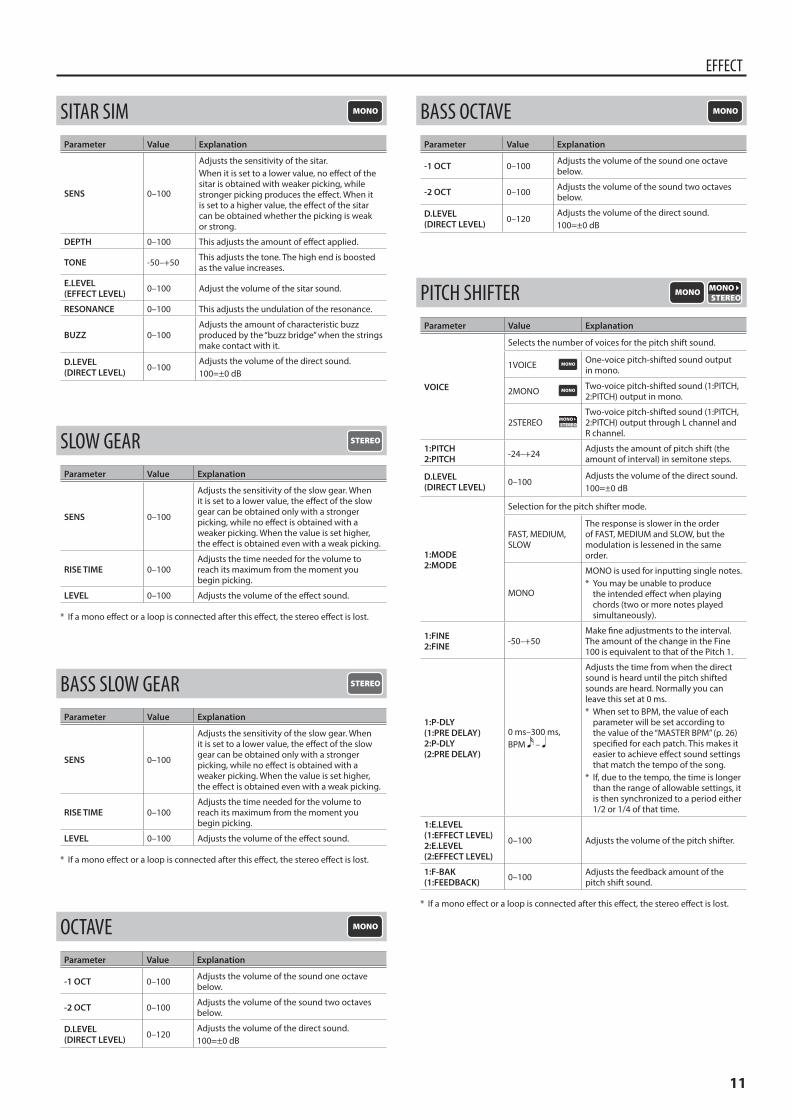
SITAR SIMParameter Value Explanation
SENS 0–100
Adjusts the sensitivity of the sitar.When it is set to a lower value, no effect of the sitar is obtained with weaker picking, while stronger picking produces the effect. When it is set to a higher value, the effect of the sitar can be obtained whether the picking is weak or strong.
DEPTH 0–100 This adjusts the amount of effect applied.
TONE -50–+50 This adjusts the tone. The high end is boosted as the value increases.
E.LEVEL (EFFECT LEVEL) 0–100 Adjust the volume of the sitar sound.
RESONANCE 0–100 This adjusts the undulation of the resonance.
BUZZ 0–100Adjusts the amount of characteristic buzz produced by the “buzz bridge” when the strings make contact with it.
D.LEVEL(DIRECT LEVEL) 0–100
Adjusts the volume of the direct sound.100=±0 dB
SLOW GEARParameter Value Explanation
SENS 0–100
Adjusts the sensitivity of the slow gear. When it is set to a lower value, the effect of the slow gear can be obtained only with a stronger picking, while no effect is obtained with a weaker picking. When the value is set higher, the effect is obtained even with a weak picking.
RISE TIME 0–100Adjusts the time needed for the volume to reach its maximum from the moment you begin picking.
LEVEL 0–100 Adjusts the volume of the effect sound.
* If a mono effect or a loop is connected after this effect, the stereo effect is lost.
BASS SLOW GEARParameter Value Explanation
SENS 0–100
Adjusts the sensitivity of the slow gear. When it is set to a lower value, the effect of the slow gear can be obtained only with a stronger picking, while no effect is obtained with a weaker picking. When the value is set higher, the effect is obtained even with a weak picking.
RISE TIME 0–100Adjusts the time needed for the volume to reach its maximum from the moment you begin picking.
LEVEL 0–100 Adjusts the volume of the effect sound.
* If a mono effect or a loop is connected after this effect, the stereo effect is lost.
OCTAVEParameter Value Explanation
-1 OCT 0–100 Adjusts the volume of the sound one octave below.
-2 OCT 0–100 Adjusts the volume of the sound two octaves below.
D.LEVEL (DIRECT LEVEL) 0–120
Adjusts the volume of the direct sound.100=±0 dB
BASS OCTAVEParameter Value Explanation
-1 OCT 0–100 Adjusts the volume of the sound one octave below.
-2 OCT 0–100 Adjusts the volume of the sound two octaves below.
D.LEVEL (DIRECT LEVEL) 0–120
Adjusts the volume of the direct sound.100=±0 dB
PITCH SHIFTERParameter Value Explanation
VOICE
Selects the number of voices for the pitch shift sound.
1VOICE One-voice pitch-shifted sound output in mono.
2MONO Two-voice pitch-shifted sound (1:PITCH, 2:PITCH) output in mono.
2STEREOTwo-voice pitch-shifted sound (1:PITCH, 2:PITCH) output through L channel and R channel.
1:PITCH2:PITCH -24–+24 Adjusts the amount of pitch shift (the
amount of interval) in semitone steps.
D.LEVEL(DIRECT LEVEL) 0–100
Adjusts the volume of the direct sound.100=±0 dB
1:MODE2:MODE
Selection for the pitch shifter mode.
FAST, MEDIUM, SLOW
The response is slower in the order of FAST, MEDIUM and SLOW, but the modulation is lessened in the same order.
MONO
MONO is used for inputting single notes.* You may be unable to produce
the intended effect when playing chords (two or more notes played simultaneously).
1:FINE2:FINE -50–+50
Make fine adjustments to the interval. The amount of the change in the Fine 100 is equivalent to that of the Pitch 1.
1:P-DLY(1:PRE DELAY)2:P-DLY(2:PRE DELAY)
0 ms–300 ms, BPM –
Adjusts the time from when the direct sound is heard until the pitch shifted sounds are heard. Normally you can leave this set at 0 ms.* When set to BPM, the value of each
parameter will be set according to the value of the “MASTER BPM” (p. 26) specified for each patch. This makes it easier to achieve effect sound settings that match the tempo of the song.
* If, due to the tempo, the time is longer than the range of allowable settings, it is then synchronized to a period either 1/2 or 1/4 of that time.
1:E.LEVEL(1:EFFECT LEVEL)2:E.LEVEL(2:EFFECT LEVEL)
0–100 Adjusts the volume of the pitch shifter.
1:F-BAK(1:FEEDBACK) 0–100 Adjusts the feedback amount of the
pitch shift sound.
* If a mono effect or a loop is connected after this effect, the stereo effect is lost.
12
EFFECT
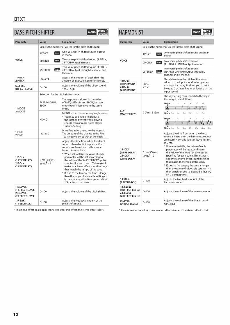
BASS PITCH SHIFTERParameter Value Explanation
VOICE
Selects the number of voices for the pitch shift sound.
1VOICE One-voice pitch-shifted sound output in mono.
2MONO Two-voice pitch-shifted sound (1:PITCH, 2:PITCH) output in mono.
2STEREOTwo-voice pitch-shifted sound (1:PITCH, 2:PITCH) output through L channel and R channel.
1:PITCH2:PITCH -24–+24 Adjusts the amount of pitch shift (the
amount of interval) in semitone steps.
D.LEVEL(DIRECT LEVEL) 0–100
Adjusts the volume of the direct sound.100=±0 dB
1:MODE2:MODE
Selection for the pitch shifter mode.
FAST, MEDIUM, SLOW
The response is slower in the order of FAST, MEDIUM and SLOW, but the modulation is lessened in the same order.
MONO
MONO is used for inputting single notes.* You may be unable to produce
the intended effect when playing chords (two or more notes played simultaneously).
1:FINE2:FINE -50–+50
Make fine adjustments to the interval. The amount of the change in the Fine 100 is equivalent to that of the Pitch 1.
1:P-DLY(1:PRE DELAY)2:P-DLY(2:PRE DELAY)
0 ms–300 ms, BPM –
Adjusts the time from when the direct sound is heard until the pitch shifted sounds are heard. Normally you can leave this set at 0 ms.* When set to BPM, the value of each
parameter will be set according to the value of the “MASTER BPM” (p. 26) specified for each patch. This makes it easier to achieve effect sound settings that match the tempo of the song.
* If, due to the tempo, the time is longer than the range of allowable settings, it is then synchronized to a period either 1/2 or 1/4 of that time.
1:E.LEVEL(1:EFFECT LEVEL)2:E.LEVEL(2:EFFECT LEVEL)
0–100 Adjusts the volume of the pitch shifter.
1:F-BAK(1:FEEDBACK) 0–100 Adjusts the feedback amount of the
pitch shift sound.
* If a mono effect or a loop is connected after this effect, the stereo effect is lost.
HARMONISTParameter Value Explanation
VOICE
Selects the number of voices for the pitch shift sound.
1VOICE One-voice pitch-shifted sound output in mono.
2MONO Two-voice pitch-shifted sound (1:HARM, 2:HARM) output in mono.
2STEREOTwo-voice pitch-shifted sound (1:HARM, 2:HARM) output through L channel and R channel.
1:HARM(1:HARMONY)2:HARM(2:HARMONY)
-2oct–+2oct
This determines the pitch of the sound added to the input sound, when you are making a harmony. It allows you to set it by up to 2 octaves higher or lower than the input sound.
KEY (MASTER KEY) C (Am)–B (G#m)
The key setting corresponds to the key of the song (¾, ²) as follows.
Major
Major
Minor
Minor
1:P-DLY(1:PRE DELAY)2:P-DLY(2:PRE DELAY)
0 ms–300 ms, BPM –
Adjusts the time from when the direct sound is heard until the harmonist sounds are heard. Normally you can leave this set at 0 ms.* When set to BPM, the value of each
parameter will be set according to the value of the “MASTER BPM” (p. 26) specified for each patch. This makes it easier to achieve effect sound settings that match the tempo of the song.
* If, due to the tempo, the time is longer than the range of allowable settings, it is then synchronized to a period either 1/2 or 1/4 of that time.
1:F-BAK(1:FEEDBACK) 0–100 Adjusts the feedback amount of the
harmonist sound.
1:E.LEVEL(1:EFFECT LEVEL)2:E.LEVEL(2:EFFECT LEVEL)
0–100 Adjusts the volume of the harmony sound.
D.LEVEL (DIRECT LEVEL) 0–100
Adjusts the volume of the direct sound.100=±0 dB
* If a mono effect or a loop is connected after this effect, the stereo effect is lost.
13
EFFECT
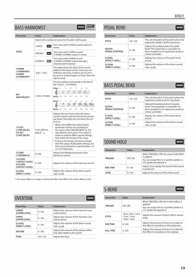
BASS HARMONISTParameter Value Explanation
VOICE
Selects the number of voices for the pitch shift sound.
1VOICE One-voice pitch-shifted sound output in mono.
2MONO Two-voice pitch-shifted sound (1:HARM, 2:HARM) output in mono.
2STEREOTwo-voice pitch-shifted sound (1:HARM, 2:HARM) output through L channel and R channel.
1:HARM(1:HARMONY)2:HARM(2:HARMONY)
-2oct–+2oct
This determines the pitch of the sound added to the input sound, when you are making a harmony. It allows you to set it by up to 2 octaves higher or lower than the input sound.
KEY (MASTER KEY) C (Am)–B (G#m)
The key setting corresponds to the key of the song (¾, ²) as follows.
Major
Major
Minor
Minor
1:P-DLY(1:PRE DELAY)2:P-DLY(2:PRE DELAY)
0 ms–300 ms, BPM –
Adjusts the time from when the direct sound is heard until the harmonist sounds are heard. Normally you can leave this set at 0 ms.* When set to BPM, the value of each
parameter will be set according to the value of the “MASTER BPM” (p. 26) specified for each patch. This makes it easier to achieve effect sound settings that match the tempo of the song.
* If, due to the tempo, the time is longer than the range of allowable settings, it is then synchronized to a period either 1/2 or 1/4 of that time.
1:F-BAK(1:FEEDBACK) 0–100 Adjusts the feedback amount of the
harmonist sound.
1:E.LEVEL(1:EFFECT LEVEL)2:E.LEVEL(2:EFFECT LEVEL)
0–100 Adjusts the volume of the harmony sound.
D.LEVEL (DIRECT LEVEL) 0–100
Adjusts the volume of the direct sound.100=±0 dB
* If a mono effect or a loop is connected after this effect, the stereo effect is lost.
OVERTONEParameter Value Explanation
LOWER(LOWER LEVEL) 0–100 Adjusts the volume of the harmonic one
octave below.
UPPER(UPPER LEVEL) 0–100 Adjusts the volume of the harmonic one
octave above.
D.LEVEL (DIRECT LEVEL) 0–100
Adjusts the volume of the direct sound.100=±0 dB
DETUNE 0–100 Adjusts the amount of the detune effect that adds depth to the sound.
TONE -50–+50 Adjusts the tone.
PEDAL BENDParameter Value Explanation
PITCH -24–+24 This sets the pitch at the point where the expression pedal is all the way down.
PD.POS(PEDAL POSITION) 0–100
Adjusts the pedal position for pedal bend. This parameter is used after it’s been assigned to an expression pedal or similar controller.
E.LEVEL (EFFECT LEVEL) 0–100 Adjusts the volume of the pitch bend
sound.
D.LEVEL (DIRECT LEVEL) 0–100
Adjusts the volume of the direct sound.100=±0 dB
BASS PEDAL BENDParameter Value Explanation
PITCH -24–+24 This sets the pitch at the point where the expression pedal is all the way down.
PD.POS(PEDAL POSITION) 0–100
Adjusts the pedal position for pedal bend. This parameter is used after it’s been assigned to an expression pedal or similar controller.
E.LEVEL (EFFECT LEVEL) 0–100 Adjusts the volume of the pitch bend
sound.
D.LEVEL (DIRECT LEVEL) 0–100
Adjusts the volume of the direct sound.100=±0 dB
SOUND HOLDParameter Value Explanation
TRIGGER OFF, ON
When TRIGGER is ON, the sound hold effect is applied.You can assign this to a number pedal or a CTL pedal and operate it.
RISE TIME 0–100 Adjusts how rapidly the Sound Hold sound is produced.
LEVEL 0–120 Adjusts the volume of the hold sound.
S-BENDParameter Value Explanation
TRIGGER OFF, ON
When TRIGGER is ON, the S-bend effect is applied.You can assign this to a number pedal or a CTL pedal and operate it.
PITCH-3oct, -2oct, -1oct, +1oct, +2oct, +3oct, +4oct
Adjusts the amount of pitch shift in octave steps.
RISE TIME 0–100 Adjusts the amount of time it is to take for the effect to transition to the maximum.
FALL TIME 0–100 Adjusts the amount of time it is to take for the effect to transition to the original.
14
EFFECT
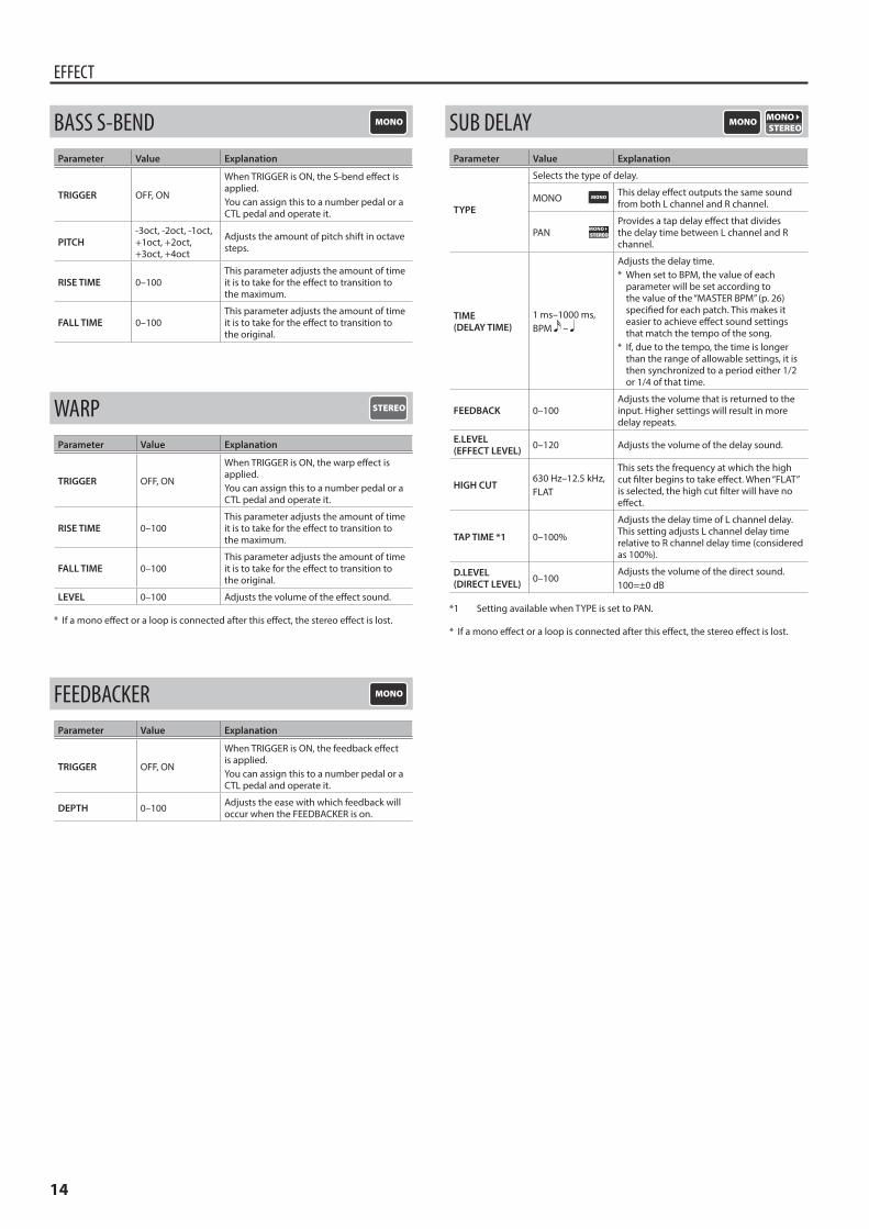
BASS S-BENDParameter Value Explanation
TRIGGER OFF, ON
When TRIGGER is ON, the S-bend effect is applied.You can assign this to a number pedal or a CTL pedal and operate it.
PITCH-3oct, -2oct, -1oct, +1oct, +2oct, +3oct, +4oct
Adjusts the amount of pitch shift in octave steps.
RISE TIME 0–100This parameter adjusts the amount of time it is to take for the effect to transition to the maximum.
FALL TIME 0–100This parameter adjusts the amount of time it is to take for the effect to transition to the original.
WARPParameter Value Explanation
TRIGGER OFF, ON
When TRIGGER is ON, the warp effect is applied.You can assign this to a number pedal or a CTL pedal and operate it.
RISE TIME 0–100This parameter adjusts the amount of time it is to take for the effect to transition to the maximum.
FALL TIME 0–100This parameter adjusts the amount of time it is to take for the effect to transition to the original.
LEVEL 0–100 Adjusts the volume of the effect sound.
* If a mono effect or a loop is connected after this effect, the stereo effect is lost.
FEEDBACKERParameter Value Explanation
TRIGGER OFF, ON
When TRIGGER is ON, the feedback effect is applied.You can assign this to a number pedal or a CTL pedal and operate it.
DEPTH 0–100 Adjusts the ease with which feedback will occur when the FEEDBACKER is on.
SUB DELAYParameter Value Explanation
TYPE
Selects the type of delay.
MONO This delay effect outputs the same sound from both L channel and R channel.
PANProvides a tap delay effect that divides the delay time between L channel and R channel.
TIME (DELAY TIME)
1 ms–1000 ms, BPM –
Adjusts the delay time.* When set to BPM, the value of each
parameter will be set according to the value of the “MASTER BPM” (p. 26) specified for each patch. This makes it easier to achieve effect sound settings that match the tempo of the song.
* If, due to the tempo, the time is longer than the range of allowable settings, it is then synchronized to a period either 1/2 or 1/4 of that time.
FEEDBACK 0–100Adjusts the volume that is returned to the input. Higher settings will result in more delay repeats.
E.LEVEL (EFFECT LEVEL) 0–120 Adjusts the volume of the delay sound.
HIGH CUT630 Hz–12.5 kHz, FLAT
This sets the frequency at which the high cut filter begins to take effect. When “FLAT” is selected, the high cut filter will have no effect.
TAP TIME *1 0–100%
Adjusts the delay time of L channel delay. This setting adjusts L channel delay time relative to R channel delay time (considered as 100%).
D.LEVEL (DIRECT LEVEL) 0–100
Adjusts the volume of the direct sound.100=±0 dB
*1 Setting available when TYPE is set to PAN.
* If a mono effect or a loop is connected after this effect, the stereo effect is lost.
15
EFFECT
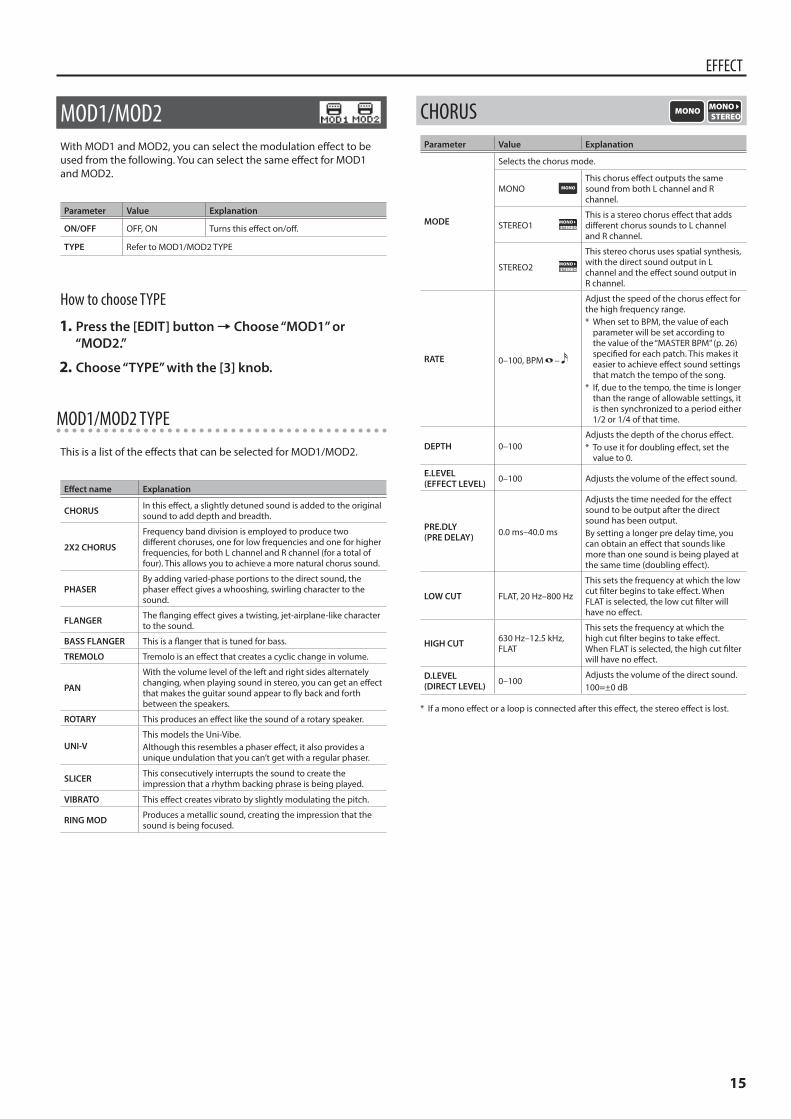
MOD1/MOD2With MOD1 and MOD2, you can select the modulation effect to be used from the following. You can select the same effect for MOD1 and MOD2.
Parameter Value Explanation
ON/OFF OFF, ON Turns this effect on/off.
TYPE Refer to MOD1/MOD2 TYPE
How to choose TYPE
1 Press the [EDIT] button0Choose “MOD1” or “MOD2.”
2 Choose “TYPE” with the [3] knob.
MOD1/MOD2 TYPE
This is a list of the effects that can be selected for MOD1/MOD2.
Effect name Explanation
CHORUS In this effect, a slightly detuned sound is added to the original sound to add depth and breadth.
2X2 CHORUS
Frequency band division is employed to produce two different choruses, one for low frequencies and one for higher frequencies, for both L channel and R channel (for a total of four). This allows you to achieve a more natural chorus sound.
PHASERBy adding varied-phase portions to the direct sound, the phaser effect gives a whooshing, swirling character to the sound.
FLANGER The flanging effect gives a twisting, jet-airplane-like character to the sound.
BASS FLANGER This is a flanger that is tuned for bass.
TREMOLO Tremolo is an effect that creates a cyclic change in volume.
PAN
With the volume level of the left and right sides alternately changing, when playing sound in stereo, you can get an effect that makes the guitar sound appear to fly back and forth between the speakers.
ROTARY This produces an effect like the sound of a rotary speaker.
UNI-VThis models the Uni-Vibe.Although this resembles a phaser effect, it also provides a unique undulation that you can’t get with a regular phaser.
SLICER This consecutively interrupts the sound to create the impression that a rhythm backing phrase is being played.
VIBRATO This effect creates vibrato by slightly modulating the pitch.
RING MOD Produces a metallic sound, creating the impression that the sound is being focused.
CHORUSParameter Value Explanation
MODE
Selects the chorus mode.
MONOThis chorus effect outputs the same sound from both L channel and R channel.
STEREO1This is a stereo chorus effect that adds different chorus sounds to L channel and R channel.
STEREO2
This stereo chorus uses spatial synthesis, with the direct sound output in L channel and the effect sound output in R channel.
RATE 0–100, BPM –
Adjust the speed of the chorus effect for the high frequency range.* When set to BPM, the value of each
parameter will be set according to the value of the “MASTER BPM” (p. 26) specified for each patch. This makes it easier to achieve effect sound settings that match the tempo of the song.
* If, due to the tempo, the time is longer than the range of allowable settings, it is then synchronized to a period either 1/2 or 1/4 of that time.
DEPTH 0–100Adjusts the depth of the chorus effect.* To use it for doubling effect, set the
value to 0.
E.LEVEL (EFFECT LEVEL) 0–100 Adjusts the volume of the effect sound.
PRE.DLY(PRE DELAY) 0.0 ms–40.0 ms
Adjusts the time needed for the effect sound to be output after the direct sound has been output. By setting a longer pre delay time, you can obtain an effect that sounds like more than one sound is being played at the same time (doubling effect).
LOW CUT FLAT, 20 Hz–800 Hz
This sets the frequency at which the low cut filter begins to take effect. When FLAT is selected, the low cut filter will have no effect.
HIGH CUT 630 Hz–12.5 kHz, FLAT
This sets the frequency at which the high cut filter begins to take effect. When FLAT is selected, the high cut filter will have no effect.
D.LEVEL (DIRECT LEVEL) 0–100
Adjusts the volume of the direct sound.100=±0 dB
* If a mono effect or a loop is connected after this effect, the stereo effect is lost.
16
EFFECT
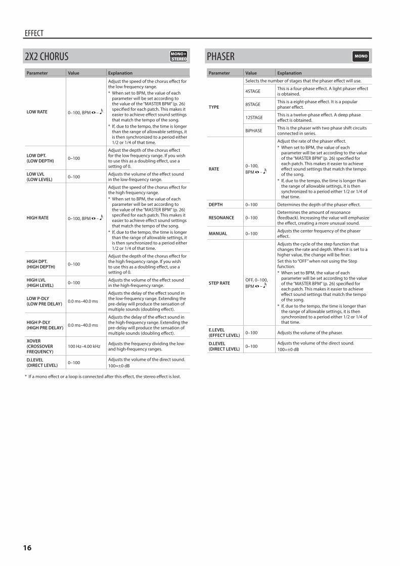
2X2 CHORUSParameter Value Explanation
LOW RATE 0–100, BPM –
Adjust the speed of the chorus effect for the low frequency range.* When set to BPM, the value of each
parameter will be set according to the value of the “MASTER BPM” (p. 26) specified for each patch. This makes it easier to achieve effect sound settings that match the tempo of the song.
* If, due to the tempo, the time is longer than the range of allowable settings, it is then synchronized to a period either 1/2 or 1/4 of that time.
LOW DPT.(LOW DEPTH) 0–100
Adjust the depth of the chorus effect for the low frequency range. If you wish to use this as a doubling effect, use a setting of 0.
LOW LVL(LOW LEVEL) 0–100 Adjusts the volume of the effect sound
in the low-frequency range.
HIGH RATE 0–100, BPM –
Adjust the speed of the chorus effect for the high frequency range.* When set to BPM, the value of each
parameter will be set according to the value of the “MASTER BPM” (p. 26) specified for each patch. This makes it easier to achieve effect sound settings that match the tempo of the song.
* If, due to the tempo, the time is longer than the range of allowable settings, it is then synchronized to a period either 1/2 or 1/4 of that time.
HIGH DPT.(HIGH DEPTH) 0–100
Adjust the depth of the chorus effect for the high frequency range. If you wish to use this as a doubling effect, use a setting of 0.
HIGH LVL(HIGH LEVEL) 0–100 Adjusts the volume of the effect sound
in the high-frequency range.
LOW P-DLY(LOW PRE DELAY) 0.0 ms–40.0 ms
Adjusts the delay of the effect sound in the low-frequency range. Extending the pre-delay will produce the sensation of multiple sounds (doubling effect).
HIGH P-DLY(HIGH PRE DELAY) 0.0 ms–40.0 ms
Adjusts the delay of the effect sound in the high-frequency range. Extending the pre-delay will produce the sensation of multiple sounds (doubling effect).
XOVER(CROSSOVER FREQUENCY)
100 Hz–4.00 kHz Adjusts the frequency dividing the low- and high-frequency ranges.
D.LEVEL(DIRECT LEVEL) 0–100
Adjusts the volume of the direct sound.100=±0 dB
* If a mono effect or a loop is connected after this effect, the stereo effect is lost.
PHASERParameter Value Explanation
TYPE
Selects the number of stages that the phaser effect will use.
4STAGE This is a four-phase effect. A light phaser effect is obtained.
8STAGE This is a eight-phase effect. It is a popular phaser effect.
12STAGE This is a twelve-phase effect. A deep phase effect is obtained.
BiPHASE This is the phaser with two phase shift circuits connected in series.
RATE0–100, BPM –
Adjust the rate of the phaser effect.* When set to BPM, the value of each
parameter will be set according to the value of the “MASTER BPM” (p. 26) specified for each patch. This makes it easier to achieve effect sound settings that match the tempo of the song.
* If, due to the tempo, the time is longer than the range of allowable settings, it is then synchronized to a period either 1/2 or 1/4 of that time.
DEPTH 0–100 Determines the depth of the phaser effect.
RESONANCE 0–100Determines the amount of resonance (feedback). Increasing the value will emphasize the effect, creating a more unusual sound.
MANUAL 0–100 Adjusts the center frequency of the phaser effect.
STEP RATEOFF, 0–100, BPM –
Adjusts the cycle of the step function that changes the rate and depth. When it is set to a higher value, the change will be finer. Set this to “OFF” when not using the Step function.* When set to BPM, the value of each
parameter will be set according to the value of the “MASTER BPM” (p. 26) specified for each patch. This makes it easier to achieve effect sound settings that match the tempo of the song.
* If, due to the tempo, the time is longer than the range of allowable settings, it is then synchronized to a period either 1/2 or 1/4 of that time.
E.LEVEL (EFFECT LEVEL) 0–100 Adjusts the volume of the phaser.
D.LEVEL (DIRECT LEVEL) 0–100
Adjusts the volume of the direct sound.100=±0 dB
17
EFFECT
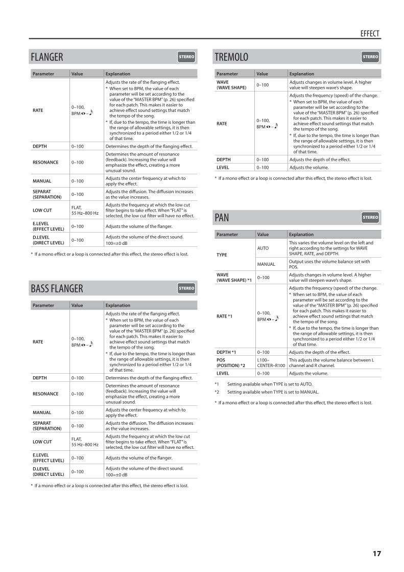
FLANGERParameter Value Explanation
RATE0–100, BPM –
Adjusts the rate of the flanging effect.* When set to BPM, the value of each
parameter will be set according to the value of the “MASTER BPM” (p. 26) specified for each patch. This makes it easier to achieve effect sound settings that match the tempo of the song.
* If, due to the tempo, the time is longer than the range of allowable settings, it is then synchronized to a period either 1/2 or 1/4 of that time.
DEPTH 0–100 Determines the depth of the flanging effect.
RESONANCE 0–100
Determines the amount of resonance (feedback). Increasing the value will emphasize the effect, creating a more unusual sound.
MANUAL 0–100 Adjusts the center frequency at which to apply the effect.
SEPARAT(SEPARATION) 0–100 Adjusts the diffusion. The diffusion increases
as the value increases.
LOW CUT FLAT, 55 Hz–800 Hz
Adjusts the frequency at which the low cut filter begins to take effect. When “FLAT” is selected, the low cut filter will have no effect.
E.LEVEL (EFFECT LEVEL) 0–100 Adjusts the volume of the flanger.
D.LEVEL (DIRECT LEVEL) 0–100
Adjusts the volume of the direct sound.100=±0 dB
* If a mono effect or a loop is connected after this effect, the stereo effect is lost.
BASS FLANGERParameter Value Explanation
RATE0–100, BPM –
Adjusts the rate of the flanging effect.* When set to BPM, the value of each
parameter will be set according to the value of the “MASTER BPM” (p. 26) specified for each patch. This makes it easier to achieve effect sound settings that match the tempo of the song.
* If, due to the tempo, the time is longer than the range of allowable settings, it is then synchronized to a period either 1/2 or 1/4 of that time.
DEPTH 0–100 Determines the depth of the flanging effect.
RESONANCE 0–100
Determines the amount of resonance (feedback). Increasing the value will emphasize the effect, creating a more unusual sound.
MANUAL 0–100 Adjusts the center frequency at which to apply the effect.
SEPARAT(SEPARATION) 0–100 Adjusts the diffusion. The diffusion increases
as the value increases.
LOW CUT FLAT, 55 Hz–800 Hz
Adjusts the frequency at which the low cut filter begins to take effect. When “FLAT” is selected, the low cut filter will have no effect.
E.LEVEL (EFFECT LEVEL) 0–100 Adjusts the volume of the flanger.
D.LEVEL (DIRECT LEVEL) 0–100
Adjusts the volume of the direct sound.100=±0 dB
* If a mono effect or a loop is connected after this effect, the stereo effect is lost.
TREMOLOParameter Value Explanation
WAVE(WAVE SHAPE) 0–100 Adjusts changes in volume level. A higher
value will steepen wave’s shape.
RATE0–100, BPM –
Adjusts the frequency (speed) of the change.* When set to BPM, the value of each
parameter will be set according to the value of the “MASTER BPM” (p. 26) specified for each patch. This makes it easier to achieve effect sound settings that match the tempo of the song.
* If, due to the tempo, the time is longer than the range of allowable settings, it is then synchronized to a period either 1/2 or 1/4 of that time.
DEPTH 0–100 Adjusts the depth of the effect.
LEVEL 0–100 Adjusts the volume.
* If a mono effect or a loop is connected after this effect, the stereo effect is lost.
PANParameter Value Explanation
TYPEAUTO
This varies the volume level on the left and right according to the settings for WAVE SHAPE, RATE, and DEPTH.
MANUAL Output uses the volume balance set with POS.
WAVE(WAVE SHAPE) *1 0–100 Adjusts changes in volume level. A higher
value will steepen wave’s shape.
RATE *10–100, BPM –
Adjusts the frequency (speed) of the change.* When set to BPM, the value of each
parameter will be set according to the value of the “MASTER BPM” (p. 26) specified for each patch. This makes it easier to achieve effect sound settings that match the tempo of the song.
* If, due to the tempo, the time is longer than the range of allowable settings, it is then synchronized to a period either 1/2 or 1/4 of that time.
DEPTH *1 0–100 Adjusts the depth of the effect.
POS(POSITION) *2
L100–CENTER–R100
This adjusts the volume balance between L channel and R channel.
LEVEL 0–100 Adjusts the volume.
*1 Setting available when TYPE is set to AUTO.
*2 Setting available when TYPE is set to MANUAL.
* If a mono effect or a loop is connected after this effect, the stereo effect is lost.
18
EFFECT
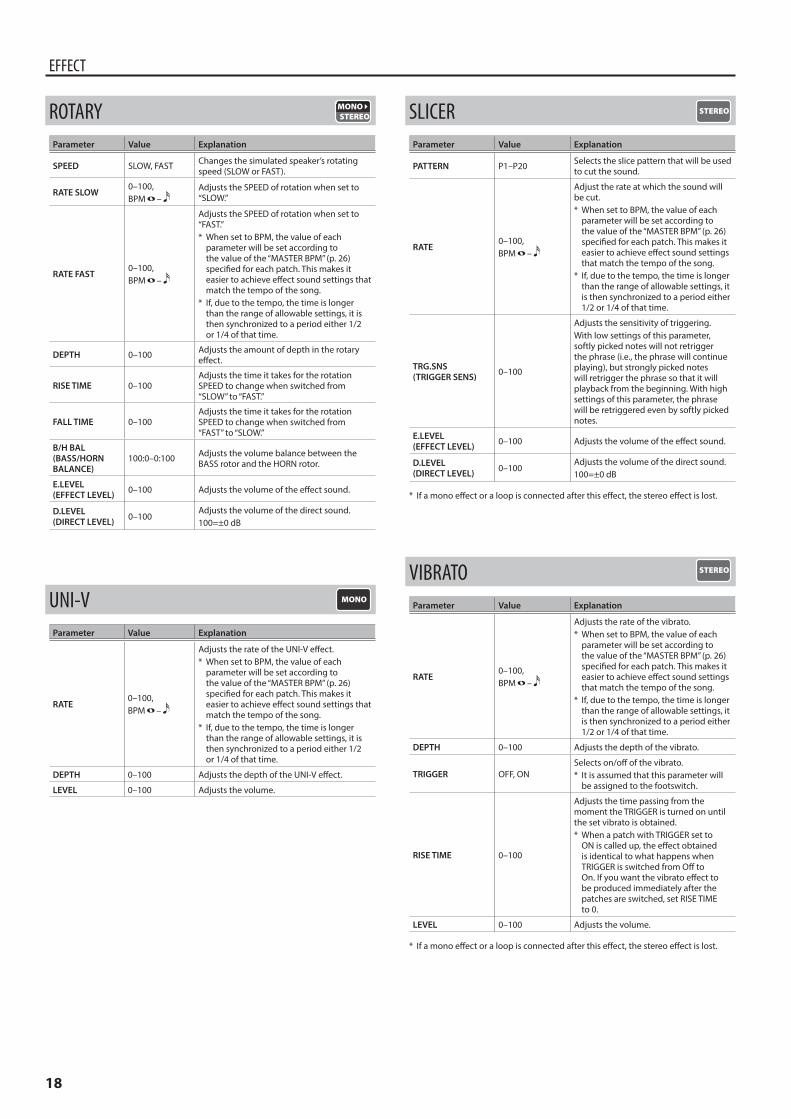
ROTARYParameter Value Explanation
SPEED SLOW, FAST Changes the simulated speaker’s rotating speed (SLOW or FAST).
RATE SLOW0–100, BPM –
Adjusts the SPEED of rotation when set to “SLOW.”
RATE FAST0–100, BPM –
Adjusts the SPEED of rotation when set to “FAST.”* When set to BPM, the value of each
parameter will be set according to the value of the “MASTER BPM” (p. 26) specified for each patch. This makes it easier to achieve effect sound settings that match the tempo of the song.
* If, due to the tempo, the time is longer than the range of allowable settings, it is then synchronized to a period either 1/2 or 1/4 of that time.
DEPTH 0–100 Adjusts the amount of depth in the rotary effect.
RISE TIME 0–100Adjusts the time it takes for the rotation SPEED to change when switched from “SLOW” to “FAST.”
FALL TIME 0–100Adjusts the time it takes for the rotation SPEED to change when switched from “FAST” to “SLOW.”
B/H BAL(BASS/HORN BALANCE)
100:0–0:100 Adjusts the volume balance between the BASS rotor and the HORN rotor.
E.LEVEL (EFFECT LEVEL) 0–100 Adjusts the volume of the effect sound.
D.LEVEL (DIRECT LEVEL) 0–100
Adjusts the volume of the direct sound.100=±0 dB
UNI-VParameter Value Explanation
RATE0–100, BPM –
Adjusts the rate of the UNI-V effect.* When set to BPM, the value of each
parameter will be set according to the value of the “MASTER BPM” (p. 26) specified for each patch. This makes it easier to achieve effect sound settings that match the tempo of the song.
* If, due to the tempo, the time is longer than the range of allowable settings, it is then synchronized to a period either 1/2 or 1/4 of that time.
DEPTH 0–100 Adjusts the depth of the UNI-V effect.
LEVEL 0–100 Adjusts the volume.
SLICERParameter Value Explanation
PATTERN P1–P20 Selects the slice pattern that will be used to cut the sound.
RATE0–100, BPM –
Adjust the rate at which the sound will be cut.* When set to BPM, the value of each
parameter will be set according to the value of the “MASTER BPM” (p. 26) specified for each patch. This makes it easier to achieve effect sound settings that match the tempo of the song.
* If, due to the tempo, the time is longer than the range of allowable settings, it is then synchronized to a period either 1/2 or 1/4 of that time.
TRG.SNS(TRIGGER SENS) 0–100
Adjusts the sensitivity of triggering.With low settings of this parameter, softly picked notes will not retrigger the phrase (i.e., the phrase will continue playing), but strongly picked notes will retrigger the phrase so that it will playback from the beginning. With high settings of this parameter, the phrase will be retriggered even by softly picked notes.
E.LEVEL (EFFECT LEVEL) 0–100 Adjusts the volume of the effect sound.
D.LEVEL (DIRECT LEVEL) 0–100
Adjusts the volume of the direct sound.100=±0 dB
* If a mono effect or a loop is connected after this effect, the stereo effect is lost.
VIBRATOParameter Value Explanation
RATE0–100, BPM –
Adjusts the rate of the vibrato.* When set to BPM, the value of each
parameter will be set according to the value of the “MASTER BPM” (p. 26) specified for each patch. This makes it easier to achieve effect sound settings that match the tempo of the song.
* If, due to the tempo, the time is longer than the range of allowable settings, it is then synchronized to a period either 1/2 or 1/4 of that time.
DEPTH 0–100 Adjusts the depth of the vibrato.
TRIGGER OFF, ONSelects on/off of the vibrato.* It is assumed that this parameter will
be assigned to the footswitch.
RISE TIME 0–100
Adjusts the time passing from the moment the TRIGGER is turned on until the set vibrato is obtained.* When a patch with TRIGGER set to
ON is called up, the effect obtained is identical to what happens when TRIGGER is switched from Off to On. If you want the vibrato effect to be produced immediately after the patches are switched, set RISE TIME to 0.
LEVEL 0–100 Adjusts the volume.
* If a mono effect or a loop is connected after this effect, the stereo effect is lost.
19
EFFECT
RING MODParameter Value Explanation
MODE
Selects the mode for the ring modulator.
NORMAL This is a normal ring modulator.
INTELLIGENT
By ring-modulating the input signal, a bell like sound is created. The intelligent ring modulator changes the oscillation frequency according to the pitch of the input sound and therefore produces a sound with the sense of pitch, which is quite different from NORMAL.This effect does not give a satisfactory result if the pitch of the guitar sound is not correctly detected. So, you must use single notes, not chords.
FREQ(FREQUENCY) 0–100 Adjusts the frequency of the internal
oscillator.
E.LEVEL (EFFECT LEVEL) 0–100 Adjusts the volume of the effect sound.
D.LEVEL (DIRECT LEVEL) 0–100
Adjusts the volume of the direct sound.100=±0 dB
* If a mono effect or a loop is connected after this effect, the stereo effect is lost.
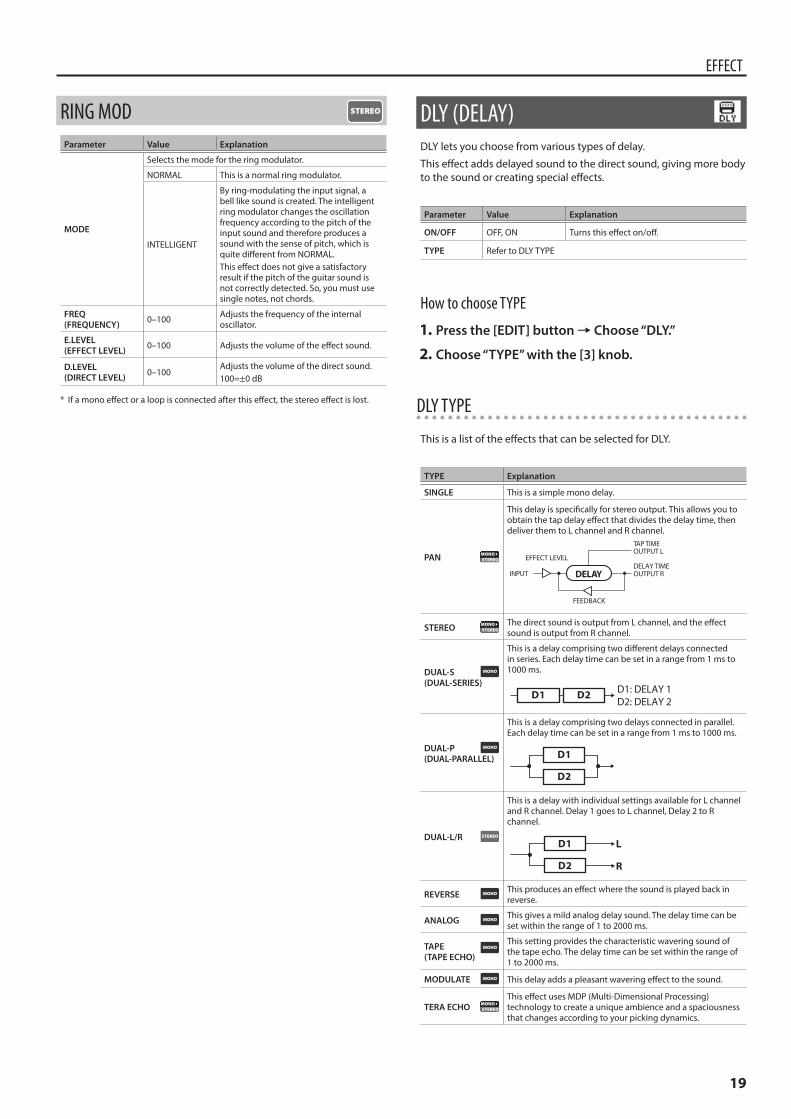
DLY (DELAY)DLY lets you choose from various types of delay.
This effect adds delayed sound to the direct sound, giving more body to the sound or creating special effects.
Parameter Value Explanation
ON/OFF OFF, ON Turns this effect on/off.
TYPE Refer to DLY TYPE
How to choose TYPE
1 Press the [EDIT] button0Choose “DLY.”
2 Choose “TYPE” with the [3] knob.
DLY TYPE
This is a list of the effects that can be selected for DLY.
TYPE Explanation
SINGLE This is a simple mono delay.
PAN
This delay is specifically for stereo output. This allows you to obtain the tap delay effect that divides the delay time, then deliver them to L channel and R channel.
INPUT
OUTPUT L
OUTPUT R
FEEDBACK
DELAY TIMEEFFECT LEVEL
DELAY
TAP TIME
STEREO The direct sound is output from L channel, and the effect sound is output from R channel.
DUAL-S(DUAL-SERIES)
This is a delay comprising two different delays connected in series. Each delay time can be set in a range from 1 ms to 1000 ms.
D1 D2 D1: DELAY 1 D2: DELAY 2
DUAL-P(DUAL-PARALLEL)
This is a delay comprising two delays connected in parallel. Each delay time can be set in a range from 1 ms to 1000 ms.
D1
D2
DUAL-L/R
This is a delay with individual settings available for L channel and R channel. Delay 1 goes to L channel, Delay 2 to R channel.
D1
D2
L
R
REVERSE This produces an effect where the sound is played back in reverse.
ANALOG This gives a mild analog delay sound. The delay time can be set within the range of 1 to 2000 ms.
TAPE (TAPE ECHO)
This setting provides the characteristic wavering sound of the tape echo. The delay time can be set within the range of 1 to 2000 ms.
MODULATE This delay adds a pleasant wavering effect to the sound.
TERA ECHOThis effect uses MDP (Multi-Dimensional Processing) technology to create a unique ambience and a spaciousness that changes according to your picking dynamics.
20
EFFECT
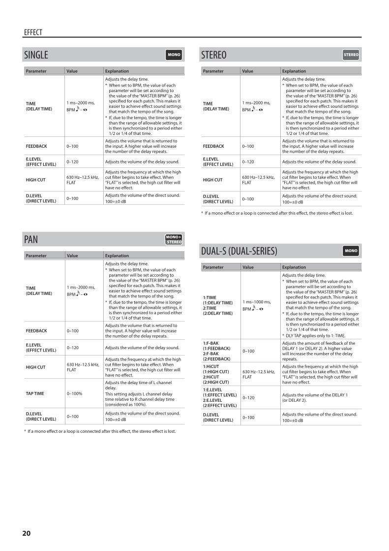
SINGLEParameter Value Explanation
TIME(DELAY TIME)
1 ms–2000 ms,
BPM –
Adjusts the delay time.* When set to BPM, the value of each
parameter will be set according to the value of the “MASTER BPM” (p. 26) specified for each patch. This makes it easier to achieve effect sound settings that match the tempo of the song.
* If, due to the tempo, the time is longer than the range of allowable settings, it is then synchronized to a period either 1/2 or 1/4 of that time.
FEEDBACK 0–100Adjusts the volume that is returned to the input. A higher value will increase the number of the delay repeats.
E.LEVEL(EFFECT LEVEL) 0–120 Adjusts the volume of the delay sound.
HIGH CUT 630 Hz–12.5 kHz, FLAT
Adjusts the frequency at which the high cut filter begins to take effect. When “FLAT” is selected, the high cut filter will have no effect.
D.LEVEL(DIRECT LEVEL) 0–100
Adjusts the volume of the direct sound.100=±0 dB
PANParameter Value Explanation
TIME(DELAY TIME)
1 ms–2000 ms,
BPM –
Adjusts the delay time.* When set to BPM, the value of each
parameter will be set according to the value of the “MASTER BPM” (p. 26) specified for each patch. This makes it easier to achieve effect sound settings that match the tempo of the song.
* If, due to the tempo, the time is longer than the range of allowable settings, it is then synchronized to a period either 1/2 or 1/4 of that time.
FEEDBACK 0–100Adjusts the volume that is returned to the input. A higher value will increase the number of the delay repeats.
E.LEVEL(EFFECT LEVEL) 0–120 Adjusts the volume of the delay sound.
HIGH CUT 630 Hz–12.5 kHz, FLAT
Adjusts the frequency at which the high cut filter begins to take effect. When “FLAT” is selected, the high cut filter will have no effect.
TAP TIME 0–100%
Adjusts the delay time of L channel delay. This setting adjusts L channel delay time relative to R channel delay time (considered as 100%).
D.LEVEL(DIRECT LEVEL) 0–100
Adjusts the volume of the direct sound.100=±0 dB
* If a mono effect or a loop is connected after this effect, the stereo effect is lost.
STEREOParameter Value Explanation
TIME(DELAY TIME)
1 ms–2000 ms,
BPM –
Adjusts the delay time.* When set to BPM, the value of each
parameter will be set according to the value of the “MASTER BPM” (p. 26) specified for each patch. This makes it easier to achieve effect sound settings that match the tempo of the song.
* If, due to the tempo, the time is longer than the range of allowable settings, it is then synchronized to a period either 1/2 or 1/4 of that time.
FEEDBACK 0–100Adjusts the volume that is returned to the input. A higher value will increase the number of the delay repeats.
E.LEVEL(EFFECT LEVEL) 0–120 Adjusts the volume of the delay sound.
HIGH CUT 630 Hz–12.5 kHz, FLAT
Adjusts the frequency at which the high cut filter begins to take effect. When “FLAT” is selected, the high cut filter will have no effect.
D.LEVEL(DIRECT LEVEL) 0–100
Adjusts the volume of the direct sound.100=±0 dB
* If a mono effect or a loop is connected after this effect, the stereo effect is lost.
DUAL-S (DUAL-SERIES)Parameter Value Explanation
1:TIME(1:DELAY TIME)2:TIME(2:DELAY TIME)
1 ms–1000 ms,
BPM –
Adjusts the delay time.* When set to BPM, the value of each
parameter will be set according to the value of the “MASTER BPM” (p. 26) specified for each patch. This makes it easier to achieve effect sound settings that match the tempo of the song.
* If, due to the tempo, the time is longer than the range of allowable settings, it is then synchronized to a period either 1/2 or 1/4 of that time.
* DLY TAP applies only to 1: TIME.
1:F-BAK(1:FEEDBACK)2:F-BAK(2:FEEDBACK)
0–100
Adjusts the amount of feedback of the DELAY 1 (or DELAY 2). A higher value will increase the number of the delay repeats.
1:HiCUT(1:HIGH CUT)2:HiCUT(2:HIGH CUT)
630 Hz–12.5 kHz, FLAT
Adjusts the frequency at which the high cut filter begins to take effect. When “FLAT” is selected, the high cut filter will have no effect.
1:E.LEVEL(1:EFFECT LEVEL)2:E.LEVEL(2:EFFECT LEVEL)
0–120 Adjusts the volume of the DELAY 1 (or DELAY 2).
D.LEVEL(DIRECT LEVEL) 0–100
Adjusts the volume of the direct sound.100=±0 dB
21
EFFECT
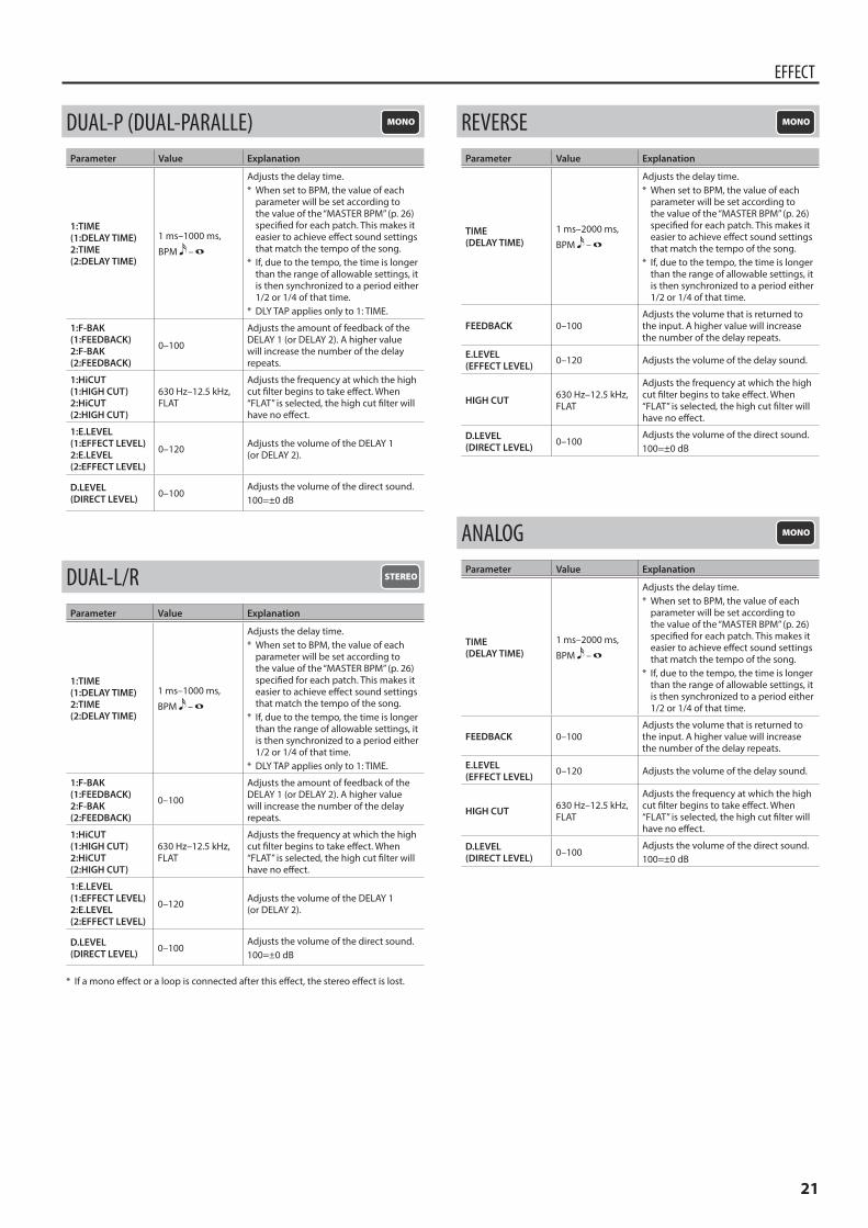
DUAL-P (DUAL-PARALLE)Parameter Value Explanation
1:TIME(1:DELAY TIME)2:TIME(2:DELAY TIME)
1 ms–1000 ms,
BPM –
Adjusts the delay time.* When set to BPM, the value of each
parameter will be set according to the value of the “MASTER BPM” (p. 26) specified for each patch. This makes it easier to achieve effect sound settings that match the tempo of the song.
* If, due to the tempo, the time is longer than the range of allowable settings, it is then synchronized to a period either 1/2 or 1/4 of that time.
* DLY TAP applies only to 1: TIME.
1:F-BAK(1:FEEDBACK)2:F-BAK(2:FEEDBACK)
0–100
Adjusts the amount of feedback of the DELAY 1 (or DELAY 2). A higher value will increase the number of the delay repeats.
1:HiCUT(1:HIGH CUT)2:HiCUT(2:HIGH CUT)
630 Hz–12.5 kHz, FLAT
Adjusts the frequency at which the high cut filter begins to take effect. When “FLAT” is selected, the high cut filter will have no effect.
1:E.LEVEL(1:EFFECT LEVEL)2:E.LEVEL(2:EFFECT LEVEL)
0–120 Adjusts the volume of the DELAY 1 (or DELAY 2).
D.LEVEL(DIRECT LEVEL) 0–100
Adjusts the volume of the direct sound.100=±0 dB
DUAL-L/RParameter Value Explanation
1:TIME(1:DELAY TIME)2:TIME(2:DELAY TIME)
1 ms–1000 ms,
BPM –
Adjusts the delay time.* When set to BPM, the value of each
parameter will be set according to the value of the “MASTER BPM” (p. 26) specified for each patch. This makes it easier to achieve effect sound settings that match the tempo of the song.
* If, due to the tempo, the time is longer than the range of allowable settings, it is then synchronized to a period either 1/2 or 1/4 of that time.
* DLY TAP applies only to 1: TIME.
1:F-BAK(1:FEEDBACK)2:F-BAK(2:FEEDBACK)
0–100
Adjusts the amount of feedback of the DELAY 1 (or DELAY 2). A higher value will increase the number of the delay repeats.
1:HiCUT(1:HIGH CUT)2:HiCUT(2:HIGH CUT)
630 Hz–12.5 kHz, FLAT
Adjusts the frequency at which the high cut filter begins to take effect. When “FLAT” is selected, the high cut filter will have no effect.
1:E.LEVEL(1:EFFECT LEVEL)2:E.LEVEL(2:EFFECT LEVEL)
0–120 Adjusts the volume of the DELAY 1 (or DELAY 2).
D.LEVEL(DIRECT LEVEL) 0–100
Adjusts the volume of the direct sound.100=±0 dB
* If a mono effect or a loop is connected after this effect, the stereo effect is lost.
REVERSEParameter Value Explanation
TIME(DELAY TIME)
1 ms–2000 ms,
BPM –
Adjusts the delay time.* When set to BPM, the value of each
parameter will be set according to the value of the “MASTER BPM” (p. 26) specified for each patch. This makes it easier to achieve effect sound settings that match the tempo of the song.
* If, due to the tempo, the time is longer than the range of allowable settings, it is then synchronized to a period either 1/2 or 1/4 of that time.
FEEDBACK 0–100Adjusts the volume that is returned to the input. A higher value will increase the number of the delay repeats.
E.LEVEL(EFFECT LEVEL) 0–120 Adjusts the volume of the delay sound.
HIGH CUT 630 Hz–12.5 kHz, FLAT
Adjusts the frequency at which the high cut filter begins to take effect. When “FLAT” is selected, the high cut filter will have no effect.
D.LEVEL(DIRECT LEVEL) 0–100
Adjusts the volume of the direct sound.100=±0 dB
ANALOGParameter Value Explanation
TIME(DELAY TIME)
1 ms–2000 ms,
BPM –
Adjusts the delay time.* When set to BPM, the value of each
parameter will be set according to the value of the “MASTER BPM” (p. 26) specified for each patch. This makes it easier to achieve effect sound settings that match the tempo of the song.
* If, due to the tempo, the time is longer than the range of allowable settings, it is then synchronized to a period either 1/2 or 1/4 of that time.
FEEDBACK 0–100Adjusts the volume that is returned to the input. A higher value will increase the number of the delay repeats.
E.LEVEL(EFFECT LEVEL) 0–120 Adjusts the volume of the delay sound.
HIGH CUT 630 Hz–12.5 kHz, FLAT
Adjusts the frequency at which the high cut filter begins to take effect. When “FLAT” is selected, the high cut filter will have no effect.
D.LEVEL(DIRECT LEVEL) 0–100
Adjusts the volume of the direct sound.100=±0 dB
22
EFFECT
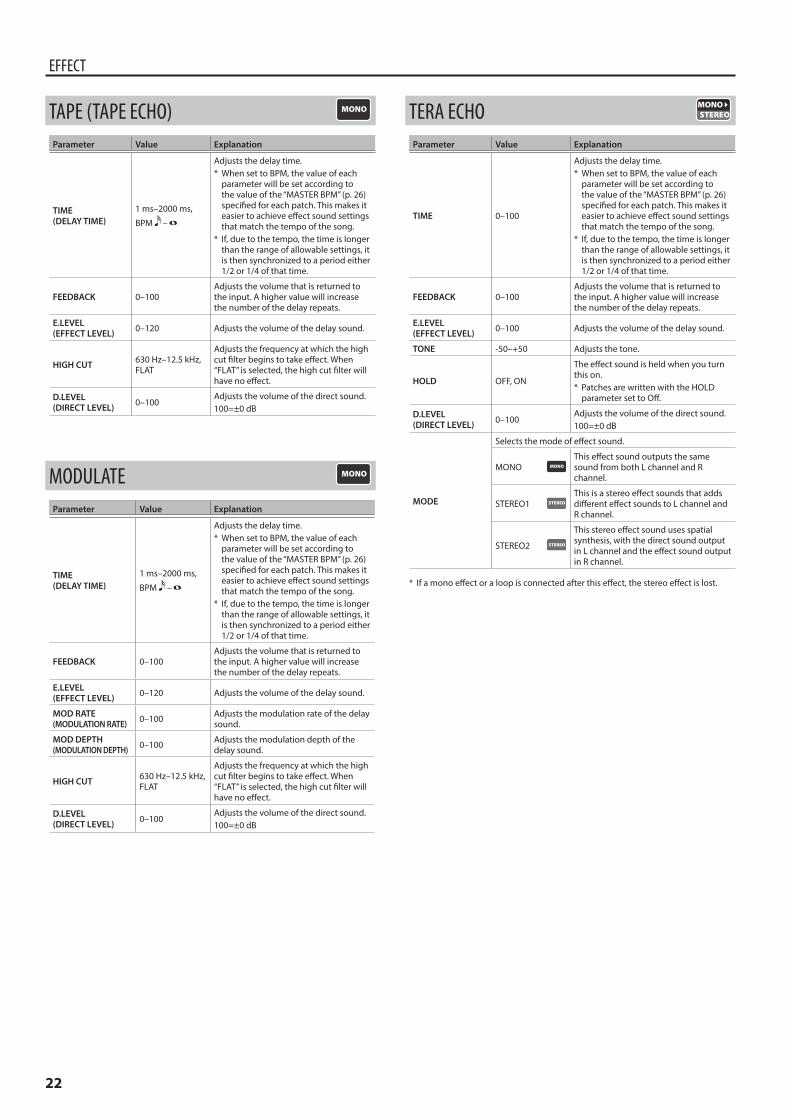
TAPE (TAPE ECHO)Parameter Value Explanation
TIME(DELAY TIME)
1 ms–2000 ms,
BPM –
Adjusts the delay time.* When set to BPM, the value of each
parameter will be set according to the value of the “MASTER BPM” (p. 26) specified for each patch. This makes it easier to achieve effect sound settings that match the tempo of the song.
* If, due to the tempo, the time is longer than the range of allowable settings, it is then synchronized to a period either 1/2 or 1/4 of that time.
FEEDBACK 0–100Adjusts the volume that is returned to the input. A higher value will increase the number of the delay repeats.
E.LEVEL(EFFECT LEVEL) 0–120 Adjusts the volume of the delay sound.
HIGH CUT 630 Hz–12.5 kHz, FLAT
Adjusts the frequency at which the high cut filter begins to take effect. When “FLAT” is selected, the high cut filter will have no effect.
D.LEVEL(DIRECT LEVEL) 0–100
Adjusts the volume of the direct sound.100=±0 dB
MODULATEParameter Value Explanation
TIME(DELAY TIME)
1 ms–2000 ms,
BPM –
Adjusts the delay time.* When set to BPM, the value of each
parameter will be set according to the value of the “MASTER BPM” (p. 26) specified for each patch. This makes it easier to achieve effect sound settings that match the tempo of the song.
* If, due to the tempo, the time is longer than the range of allowable settings, it is then synchronized to a period either 1/2 or 1/4 of that time.
FEEDBACK 0–100Adjusts the volume that is returned to the input. A higher value will increase the number of the delay repeats.
E.LEVEL(EFFECT LEVEL) 0–120 Adjusts the volume of the delay sound.
MOD RATE(MODULATION RATE) 0–100 Adjusts the modulation rate of the delay
sound.
MOD DEPTH(MODULATION DEPTH) 0–100 Adjusts the modulation depth of the
delay sound.
HIGH CUT 630 Hz–12.5 kHz, FLAT
Adjusts the frequency at which the high cut filter begins to take effect. When “FLAT” is selected, the high cut filter will have no effect.
D.LEVEL(DIRECT LEVEL) 0–100
Adjusts the volume of the direct sound.100=±0 dB
TERA ECHOParameter Value Explanation
TIME 0–100
Adjusts the delay time.* When set to BPM, the value of each
parameter will be set according to the value of the “MASTER BPM” (p. 26) specified for each patch. This makes it easier to achieve effect sound settings that match the tempo of the song.
* If, due to the tempo, the time is longer than the range of allowable settings, it is then synchronized to a period either 1/2 or 1/4 of that time.
FEEDBACK 0–100Adjusts the volume that is returned to the input. A higher value will increase the number of the delay repeats.
E.LEVEL(EFFECT LEVEL) 0–100 Adjusts the volume of the delay sound.
TONE -50–+50 Adjusts the tone.
HOLD OFF, ON
The effect sound is held when you turn this on.* Patches are written with the HOLD
parameter set to Off.
D.LEVEL(DIRECT LEVEL) 0–100
Adjusts the volume of the direct sound.100=±0 dB
MODE
Selects the mode of effect sound.
MONOThis effect sound outputs the same sound from both L channel and R channel.
STEREO1This is a stereo effect sounds that adds different effect sounds to L channel and R channel.
STEREO2
This stereo effect sound uses spatial synthesis, with the direct sound output in L channel and the effect sound output in R channel.
* If a mono effect or a loop is connected after this effect, the stereo effect is lost.
23
EFFECT
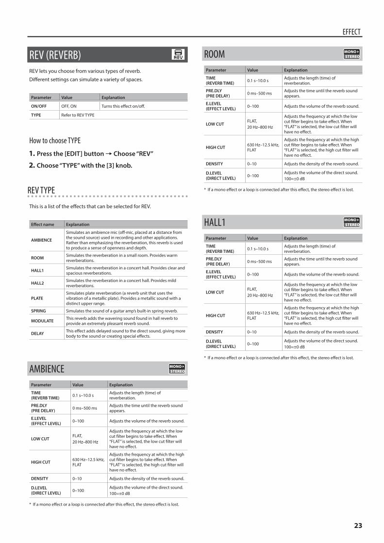
REV (REVERB)REV lets you choose from various types of reverb.
Different settings can simulate a variety of spaces.
Parameter Value Explanation
ON/OFF OFF, ON Turns this effect on/off.
TYPE Refer to REV TYPE
How to choose TYPE
1 Press the [EDIT] button0Choose “REV”
2 Choose “TYPE” with the [3] knob.
REV TYPE
This is a list of the effects that can be selected for REV.
Effect name Explanation
AMBIENCE
Simulates an ambience mic (off-mic, placed at a distance from the sound source) used in recording and other applications. Rather than emphasizing the reverberation, this reverb is used to produce a sense of openness and depth.
ROOM Simulates the reverberation in a small room. Provides warm reverberations.
HALL1 Simulates the reverberation in a concert hall. Provides clear and spacious reverberations.
HALL2 Simulates the reverberation in a concert hall. Provides mild reverberations.
PLATESimulates plate reverberation (a reverb unit that uses the vibration of a metallic plate). Provides a metallic sound with a distinct upper range.
SPRING Simulates the sound of a guitar amp’s built-in spring reverb.
MODULATE This reverb adds the wavering sound found in hall reverb to provide an extremely pleasant reverb sound.
DELAY This effect adds delayed sound to the direct sound, giving more body to the sound or creating special effects.
AMBIENCEParameter Value Explanation
TIME(REVERB TIME) 0.1 s–10.0 s Adjusts the length (time) of
reverberation.
PRE.DLY(PRE DELAY) 0 ms–500 ms Adjusts the time until the reverb sound
appears.
E.LEVEL(EFFECT LEVEL) 0–100 Adjusts the volume of the reverb sound.
LOW CUTFLAT, 20 Hz–800 Hz
Adjusts the frequency at which the low cut filter begins to take effect. When “FLAT” is selected, the low cut filter will have no effect.
HIGH CUT 630 Hz–12.5 kHz, FLAT
Adjusts the frequency at which the high cut filter begins to take effect. When “FLAT” is selected, the high cut filter will have no effect.
DENSITY 0–10 Adjusts the density of the reverb sound.
D.LEVEL(DIRECT LEVEL) 0–100
Adjusts the volume of the direct sound.100=±0 dB
* If a mono effect or a loop is connected after this effect, the stereo effect is lost.
ROOMParameter Value Explanation
TIME(REVERB TIME) 0.1 s–10.0 s Adjusts the length (time) of
reverberation.
PRE.DLY(PRE DELAY) 0 ms–500 ms Adjusts the time until the reverb sound
appears.
E.LEVEL(EFFECT LEVEL) 0–100 Adjusts the volume of the reverb sound.
LOW CUTFLAT, 20 Hz–800 Hz
Adjusts the frequency at which the low cut filter begins to take effect. When “FLAT” is selected, the low cut filter will have no effect.
HIGH CUT 630 Hz–12.5 kHz, FLAT
Adjusts the frequency at which the high cut filter begins to take effect. When “FLAT” is selected, the high cut filter will have no effect.
DENSITY 0–10 Adjusts the density of the reverb sound.
D.LEVEL(DIRECT LEVEL) 0–100
Adjusts the volume of the direct sound.100=±0 dB
* If a mono effect or a loop is connected after this effect, the stereo effect is lost.
HALL1Parameter Value Explanation
TIME(REVERB TIME) 0.1 s–10.0 s Adjusts the length (time) of
reverberation.
PRE.DLY(PRE DELAY) 0 ms–500 ms Adjusts the time until the reverb sound
appears.
E.LEVEL(EFFECT LEVEL) 0–100 Adjusts the volume of the reverb sound.
LOW CUTFLAT, 20 Hz–800 Hz
Adjusts the frequency at which the low cut filter begins to take effect. When “FLAT” is selected, the low cut filter will have no effect.
HIGH CUT 630 Hz–12.5 kHz, FLAT
Adjusts the frequency at which the high cut filter begins to take effect. When “FLAT” is selected, the high cut filter will have no effect.
DENSITY 0–10 Adjusts the density of the reverb sound.
D.LEVEL(DIRECT LEVEL) 0–100
Adjusts the volume of the direct sound.100=±0 dB
* If a mono effect or a loop is connected after this effect, the stereo effect is lost.
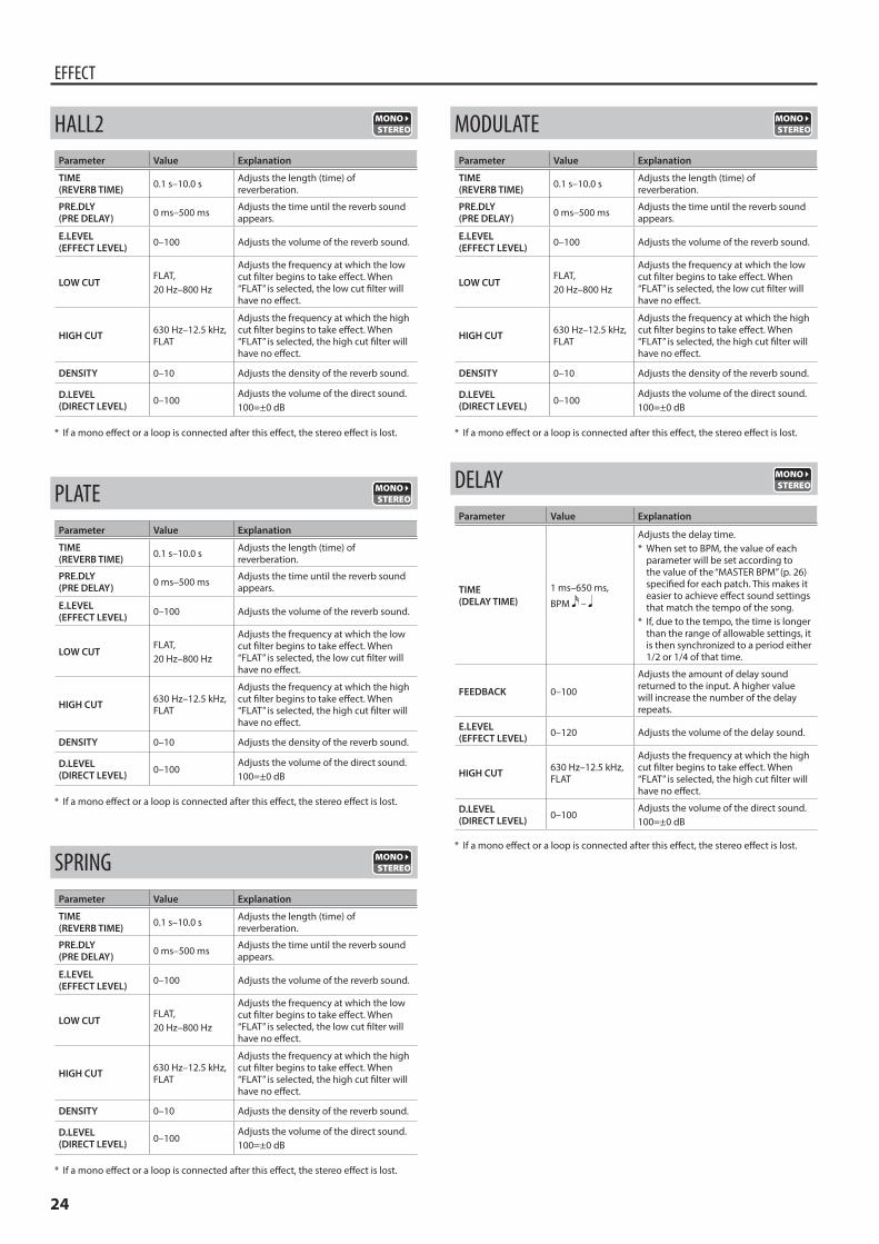
24
EFFECT
HALL2Parameter Value Explanation
TIME(REVERB TIME) 0.1 s–10.0 s Adjusts the length (time) of
reverberation.
PRE.DLY(PRE DELAY) 0 ms–500 ms Adjusts the time until the reverb sound
appears.
E.LEVEL(EFFECT LEVEL) 0–100 Adjusts the volume of the reverb sound.
LOW CUTFLAT, 20 Hz–800 Hz
Adjusts the frequency at which the low cut filter begins to take effect. When “FLAT” is selected, the low cut filter will have no effect.
HIGH CUT 630 Hz–12.5 kHz, FLAT
Adjusts the frequency at which the high cut filter begins to take effect. When “FLAT” is selected, the high cut filter will have no effect.
DENSITY 0–10 Adjusts the density of the reverb sound.
D.LEVEL(DIRECT LEVEL) 0–100
Adjusts the volume of the direct sound.100=±0 dB
* If a mono effect or a loop is connected after this effect, the stereo effect is lost.
PLATEParameter Value Explanation
TIME(REVERB TIME) 0.1 s–10.0 s Adjusts the length (time) of
reverberation.
PRE.DLY(PRE DELAY) 0 ms–500 ms Adjusts the time until the reverb sound
appears.
E.LEVEL(EFFECT LEVEL) 0–100 Adjusts the volume of the reverb sound.
LOW CUTFLAT, 20 Hz–800 Hz
Adjusts the frequency at which the low cut filter begins to take effect. When “FLAT” is selected, the low cut filter will have no effect.
HIGH CUT 630 Hz–12.5 kHz, FLAT
Adjusts the frequency at which the high cut filter begins to take effect. When “FLAT” is selected, the high cut filter will have no effect.
DENSITY 0–10 Adjusts the density of the reverb sound.
D.LEVEL(DIRECT LEVEL) 0–100
Adjusts the volume of the direct sound.100=±0 dB
* If a mono effect or a loop is connected after this effect, the stereo effect is lost.
SPRINGParameter Value Explanation
TIME(REVERB TIME) 0.1 s–10.0 s Adjusts the length (time) of
reverberation.
PRE.DLY(PRE DELAY) 0 ms–500 ms Adjusts the time until the reverb sound
appears.
E.LEVEL(EFFECT LEVEL) 0–100 Adjusts the volume of the reverb sound.
LOW CUTFLAT, 20 Hz–800 Hz
Adjusts the frequency at which the low cut filter begins to take effect. When “FLAT” is selected, the low cut filter will have no effect.
HIGH CUT 630 Hz–12.5 kHz, FLAT
Adjusts the frequency at which the high cut filter begins to take effect. When “FLAT” is selected, the high cut filter will have no effect.
DENSITY 0–10 Adjusts the density of the reverb sound.
D.LEVEL(DIRECT LEVEL) 0–100
Adjusts the volume of the direct sound.100=±0 dB
* If a mono effect or a loop is connected after this effect, the stereo effect is lost.
MODULATEParameter Value Explanation
TIME(REVERB TIME) 0.1 s–10.0 s Adjusts the length (time) of
reverberation.
PRE.DLY(PRE DELAY) 0 ms–500 ms Adjusts the time until the reverb sound
appears.
E.LEVEL(EFFECT LEVEL) 0–100 Adjusts the volume of the reverb sound.
LOW CUTFLAT, 20 Hz–800 Hz
Adjusts the frequency at which the low cut filter begins to take effect. When “FLAT” is selected, the low cut filter will have no effect.
HIGH CUT 630 Hz–12.5 kHz, FLAT
Adjusts the frequency at which the high cut filter begins to take effect. When “FLAT” is selected, the high cut filter will have no effect.
DENSITY 0–10 Adjusts the density of the reverb sound.
D.LEVEL(DIRECT LEVEL) 0–100
Adjusts the volume of the direct sound.100=±0 dB
* If a mono effect or a loop is connected after this effect, the stereo effect is lost.
DELAYParameter Value Explanation
TIME(DELAY TIME)
1 ms–650 ms,
BPM –
Adjusts the delay time.* When set to BPM, the value of each
parameter will be set according to the value of the “MASTER BPM” (p. 26) specified for each patch. This makes it easier to achieve effect sound settings that match the tempo of the song.
* If, due to the tempo, the time is longer than the range of allowable settings, it is then synchronized to a period either 1/2 or 1/4 of that time.
FEEDBACK 0–100
Adjusts the amount of delay sound returned to the input. A higher value will increase the number of the delay repeats.
E.LEVEL(EFFECT LEVEL) 0–120 Adjusts the volume of the delay sound.
HIGH CUT 630 Hz–12.5 kHz, FLAT
Adjusts the frequency at which the high cut filter begins to take effect. When “FLAT” is selected, the high cut filter will have no effect.
D.LEVEL(DIRECT LEVEL) 0–100
Adjusts the volume of the direct sound.100=±0 dB
* If a mono effect or a loop is connected after this effect, the stereo effect is lost.
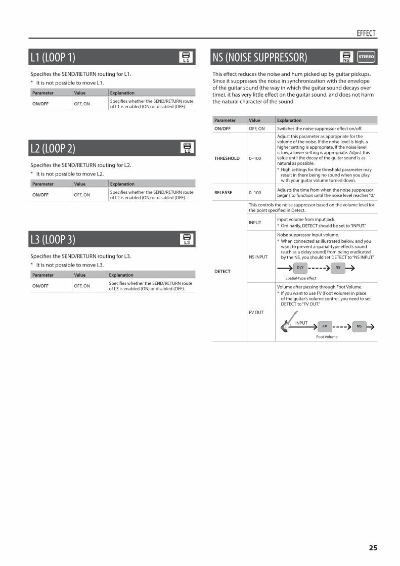
25
EFFECT
L1 (LOOP 1)Specifies the SEND/RETURN routing for L1.* It is not possible to move L1.
Parameter Value Explanation
ON/OFF OFF, ON Specifies whether the SEND/RETURN route of L1 is enabled (ON) or disabled (OFF).
L2 (LOOP 2)Specifies the SEND/RETURN routing for L2.* It is not possible to move L2.
Parameter Value Explanation
ON/OFF OFF, ON Specifies whether the SEND/RETURN route of L2 is enabled (ON) or disabled (OFF).
L3 (LOOP 3)Specifies the SEND/RETURN routing for L3.* It is not possible to move L3.
Parameter Value Explanation
ON/OFF OFF, ON Specifies whether the SEND/RETURN route of L3 is enabled (ON) or disabled (OFF).
NS (NOISE SUPPRESSOR)This effect reduces the noise and hum picked up by guitar pickups. Since it suppresses the noise in synchronization with the envelope of the guitar sound (the way in which the guitar sound decays over time), it has very little effect on the guitar sound, and does not harm the natural character of the sound.
Parameter Value Explanation
ON/OFF OFF, ON Switches the noise suppressor effect on/off.
THRESHOLD 0–100
Adjust this parameter as appropriate for the volume of the noise. If the noise level is high, a higher setting is appropriate. If the noise level is low, a lower setting is appropriate. Adjust this value until the decay of the guitar sound is as natural as possible.* High settings for the threshold parameter may
result in there being no sound when you play with your guitar volume turned down.
RELEASE 0–100 Adjusts the time from when the noise suppressor begins to function until the noise level reaches “0.”
DETECT
This controls the noise suppressor based on the volume level for the point specified in Detect.
INPUTInput volume from input jack.* Ordinarily, DETECT should be set to “INPUT.”
NS INPUT
Noise suppressor input volume.* When connected as illustrated below, and you
want to prevent a spatial-type effects sound (such as a delay sound) from being eradicated by the NS, you should set DETECT to “NS INPUT.”
Spatial-type effect
NSDLY
FV OUT
Volume after passing through Foot Volume.* If you want to use FV (Foot Volume) in place
of the guitar’s volume control, you need to set DETECT to “FV OUT.”
INPUT
Foot Volume
NSFV
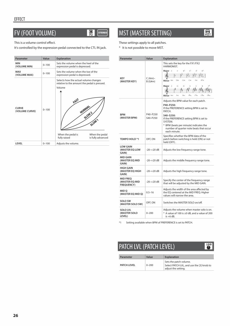
26
EFFECT
FV (FOOT VOLUME)This is a volume control effect.
It’s controlled by the expression pedal connected to the CTL IN jack.
Parameter Value Explanation
MIN(VOLUME MIN) 0–100 Sets the volume when the heel of the
expression pedal is depressed.
MAX(VOLUME MAX) 0–100 Sets the volume when the toe of the
expression pedal is depressed.
CURVE(VOLUME CURVE) 0–100
Selects how the actual volume changes relative to the amount the pedal is pressed.
NORMAL
SLOW 2
SLOW 1
FAST
When the pedal is fully raised
When the pedal is fully advanced
Volume
LEVEL 0–100 Adjusts the volume.
MST (MASTER SETTING)These settings apply to all patches.* It is not possible to move MST.
Parameter Value Explanation
KEY(MASTER KEY)
C (Am)– B (G#m)
This sets the key for the FX1/FX2 HARMONIST.
Major
Major
Minor
Minor
BPM(MASTER BPM)
P40–P250S40–P250
Adjusts the BPM value for each patch.
P40–P250:If the PREFERENCE setting BPM is set to PATCH.
S40–S250:If the PREFERENCE setting BPM is set to SYSTEM.* BPM (beats per minute) indicates the
number of quarter note beats that occur each minute.
TEMPO HOLD *1 OFF, ONSpecifies whether the BPM data of the patch before switching is held (ON) or not held (OFF).
LOW GAIN(MASTER EQ LOW GAIN)
-20–+20 dB Adjusts the low frequency range tone.
MID GAIN(MASTER EQ MID GAIN)
-20–+20 dB Adjusts the middle frequency range tone.
HIGH GAIN(MASTER EQ HIGH GAIN)
-20–+20 dB Adjusts the high frequency range tone.
MID FREQ(MASTER EQ MID FREQUENCY)
-20–+20 dB Specify the center of the frequency range that will be adjusted by the MID GAIN.
MID Q(MASTER EQ MID Q) 0.5–16
Adjusts the width of the area affected by the EQ centered at the MID FREQ. Higher values will narrow the area.
SOLO SW(MASTER SOLO SW) OFF, ON Switches the MASTER SOLO on/off.
SOLO LVL(MASTER SOLO LEVEL)
0–200Adjusts the volume when master solo is on.* A value of 100 is ±0 dB, and a value of 200
is +6 dB.
*1 Setting available when BPM of PREFERENCE is set to PATCH.
PATCH LVL (PATCH LEVEL)Parameter Value Explanation
PATCH LEVEL 0–200Sets the patch volume.Select PATCH LVL, and use the [3] knob to adjust the setting.
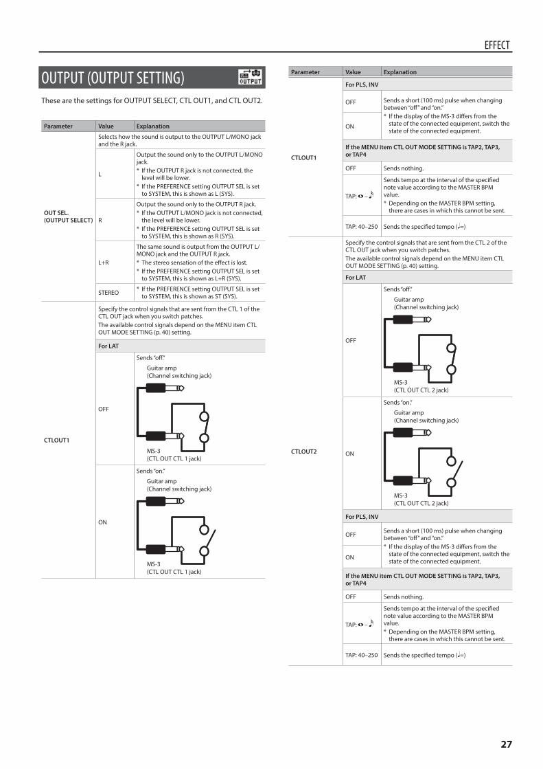
27
EFFECT
OUTPUT (OUTPUT SETTING)These are the settings for OUTPUT SELECT, CTL OUT1, and CTL OUT2.
Parameter Value Explanation
OUT SEL.(OUTPUT SELECT)
Selects how the sound is output to the OUTPUT L/MONO jack and the R jack.
L
Output the sound only to the OUTPUT L/MONO jack.* If the OUTPUT R jack is not connected, the
level will be lower.* If the PREFERENCE setting OUTPUT SEL is set
to SYSTEM, this is shown as L (SYS).
R
Output the sound only to the OUTPUT R jack.* If the OUTPUT L/MONO jack is not connected,
the level will be lower.* If the PREFERENCE setting OUTPUT SEL is set
to SYSTEM, this is shown as R (SYS).
L+R
The same sound is output from the OUTPUT L/MONO jack and the OUTPUT R jack.* The stereo sensation of the effect is lost.* If the PREFERENCE setting OUTPUT SEL is set
to SYSTEM, this is shown as L+R (SYS).
STEREO * If the PREFERENCE setting OUTPUT SEL is set to SYSTEM, this is shown as ST (SYS).
CTLOUT1
Specify the control signals that are sent from the CTL 1 of the CTL OUT jack when you switch patches.The available control signals depend on the MENU item CTL OUT MODE SETTING (p. 40) setting.
For LAT
OFF
Sends “off.”
Guitar amp(Channel switching jack)
MS-3(CTL OUT CTL 1 jack)
ON
Sends “on.”
Guitar amp(Channel switching jack)
MS-3(CTL OUT CTL 1 jack)
Parameter Value Explanation
CTLOUT1
For PLS, INV
OFF Sends a short (100 ms) pulse when changing between “off” and “on.”* If the display of the MS-3 differs from the
state of the connected equipment, switch the state of the connected equipment.
ON
If the MENU item CTL OUT MODE SETTING is TAP2, TAP3, or TAP4
OFF Sends nothing.
TAP: –
Sends tempo at the interval of the specified note value according to the MASTER BPM value.* Depending on the MASTER BPM setting,
there are cases in which this cannot be sent.
TAP: 40–250 Sends the specified tempo (¸=)
CTLOUT2
Specify the control signals that are sent from the CTL 2 of the CTL OUT jack when you switch patches.The available control signals depend on the MENU item CTL OUT MODE SETTING (p. 40) setting.
For LAT
OFF
Sends “off.”
Guitar amp(Channel switching jack)
MS-3(CTL OUT CTL 2 jack)
ON
Sends “on.”
Guitar amp(Channel switching jack)
MS-3(CTL OUT CTL 2 jack)
For PLS, INV
OFFSends a short (100 ms) pulse when changing between “off” and “on.”* If the display of the MS-3 differs from the
state of the connected equipment, switch the state of the connected equipment.
ON
If the MENU item CTL OUT MODE SETTING is TAP2, TAP3, or TAP4
OFF Sends nothing.
TAP: –
Sends tempo at the interval of the specified note value according to the MASTER BPM value.* Depending on the MASTER BPM setting,
there are cases in which this cannot be sent.
TAP: 40–250 Sends the specified tempo (¸=)
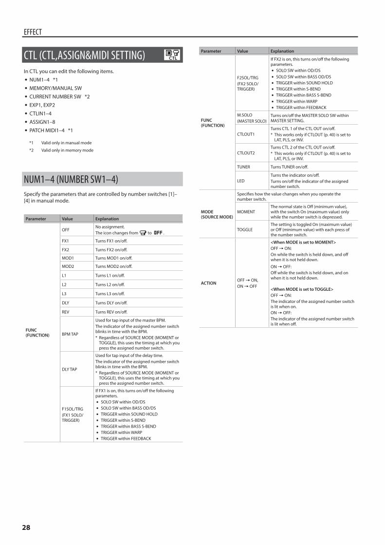
28
EFFECT
CTL (CTL,ASSIGN&MIDI SETTING) In CTL you can edit the following items.
5 NUM1–4 *1 5 MEMORY/MANUAL SW 5 CURRENT NUMBER SW *2 5 EXP1, EXP2 5 CTLIN1–4 5 ASSIGN1–8 5 PATCH MIDI1–4 *1
*1 Valid only in manual mode
*2 Valid only in memory mode
NUM1–4 (NUMBER SW1–4)Specify the parameters that are controlled by number switches [1]–[4] in manual mode.
Parameter Value Explanation
FUNC(FUNCTION)
OFFNo assignment.The icon changes from to .
FX1 Turns FX1 on/off.
FX2 Turns FX2 on/off.
MOD1 Turns MOD1 on/off.
MOD2 Turns MOD2 on/off.
L1 Turns L1 on/off.
L2 Turns L2 on/off.
L3 Turns L3 on/off.
DLY Turns DLY on/off.
REV Turns REV on/off.
BPM TAP
Used for tap input of the master BPM. The indicator of the assigned number switch blinks in time with the BPM.* Regardless of SOURCE MODE (MOMENT or
TOGGLE), this uses the timing at which you press the assigned number switch.
DLY TAP
Used for tap input of the delay time. The indicator of the assigned number switch blinks in time with the BPM.* Regardless of SOURCE MODE (MOMENT or
TOGGLE), this uses the timing at which you press the assigned number switch.
F1SOL/TRG(FX1 SOLO/TRIGGER)
If FX1 is on, this turns on/off the following parameters.
5 SOLO SW within OD/DS 5 SOLO SW within BASS OD/DS 5 TRIGGER within SOUND HOLD 5 TRIGGER within S-BEND 5 TRIGGER within BASS S-BEND 5 TRIGGER within WARP 5 TRIGGER within FEEDBACK
Parameter Value Explanation
FUNC(FUNCTION)
F2SOL/TRG(FX2 SOLO/TRIGGER)
If FX2 is on, this turns on/off the following parameters.
5 SOLO SW within OD/DS 5 SOLO SW within BASS OD/DS 5 TRIGGER within SOUND HOLD 5 TRIGGER within S-BEND 5 TRIGGER within BASS S-BEND 5 TRIGGER within WARP 5 TRIGGER within FEEDBACK
M.SOLO(MASTER SOLO)
Turns on/off the MASTER SOLO SW within MASTER SETTING.
CTLOUT1Turns CTL 1 of the CTL OUT on/off.* This works only if CTLOUT (p. 40) is set to
LAT, PLS, or INV.
CTLOUT2Turns CTL 2 of the CTL OUT on/off.* This works only if CTLOUT (p. 40) is set to
LAT, PLS, or INV.
TUNER Turns TUNER on/off.
LEDTurns the indicator on/off.Turns on/off the indicator of the assigned number switch.
MODE(SOURCE MODE)
Specifies how the value changes when you operate the number switch.
MOMENTThe normal state is Off (minimum value), with the switch On (maximum value) only while the number switch is depressed.
TOGGLEThe setting is toggled On (maximum value) or Off (minimum value) with each press of the number switch.
ACTIONOFF0ON, ON0OFF
<When MODE is set to MOMENT>OFF0ON:On while the switch is held down, and off when it is not held down.
ON0OFF:Off while the switch is held down, and on when it is not held down.
<When MODE is set to TOGGLE>OFF0ON:The indicator of the assigned number switch is lit when on.ON0OFF:The indicator of the assigned number switch is lit when off.
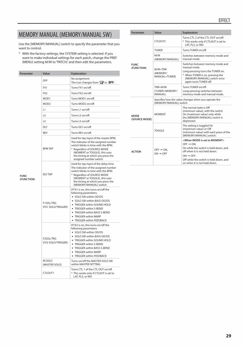
29
EFFECT
MEMORY MANUAL (MEMORY/MANUAL SW)Use the [MEMORY/MANUAL] switch to specify the parameter that you want to control.* With the factory settings, the SYSTEM setting is selected. If you
want to make individual settings for each patch, change the PREF (MENU) setting M/M to “PATCH,” and then edit the parameters.
Parameter Value Explanation
FUNC(FUNCTION)
OFFNo assignment.The icon changes from to .
FX1 Turns FX1 on/off.
FX2 Turns FX2 on/off.
MOD1 Turns MOD1 on/off.
MOD2 Turns MOD2 on/off.
L1 Turns L1 on/off.
L2 Turns L2 on/off.
L3 Turns L3 on/off.
DLY Turns DLY on/off.
REV Turns REV on/off.
BPM TAP
Used for tap input of the master BPM. The indicator of the assigned number switch blinks in time with the BPM.* Regardless of SOURCE MODE
(MOMENT or TOGGLE), this uses the timing at which you press the assigned number switch.
DLY TAP
Used for tap input of the delay time. The indicator of the assigned number switch blinks in time with the BPM.* Regardless of SOURCE MODE
(MOMENT or TOGGLE), this uses the timing at which you press the [MEMORY/MANUAL] switch.
F1SOL/TRG(FX1 SOLO/TRIGGER)
If FX1 is on, this turns on/off the following parameters.
5 SOLO SW within OD/DS 5 SOLO SW within BASS OD/DS 5 TRIGGER within SOUND HOLD 5 TRIGGER within S-BEND 5 TRIGGER within BASS S-BEND 5 TRIGGER within WARP 5 TRIGGER within FEEDBACK
F2SOL/TRG(FX2 SOLO/TRIGGER)
If FX2 is on, this turns on/off the following parameters.
5 SOLO SW within OD/DS 5 SOLO SW within BASS OD/DS 5 TRIGGER within SOUND HOLD 5 TRIGGER within S-BEND 5 TRIGGER within BASS S-BEND 5 TRIGGER within WARP 5 TRIGGER within FEEDBACK
M.SOLO(MASTER SOLO)
Turns on/off the MASTER SOLO SW within MASTER SETTING.
CTLOUT1Turns CTL 1 of the CTL OUT on/off.* This works only if CTLOUT is set to
LAT, PLS, or INV.
Parameter Value Explanation
FUNC(FUNCTION)
CTLOUT2Turns CTL 2 of the CTL OUT on/off.* This works only if CTLOUT is set to
LAT, PLS, or INV.
TUNER Turns TUNER on/off.
M/M(MEMORY/MANUAL)
Switches between memory mode and manual mode.
M/M+TNR(MEMORY/MANUAL+TUNER)
Switches between memory mode and manual mode.Long-pressing turns the TUNER on.* When TUNER is on, pressing the
[MEMORY/MANUAL] switch once again turns TUNER off.
TNR+M/M(TUNER+MEMORY/MANUAL)
Turns TUNER on/off.Long-pressing switches between memory mode and manual mode.
MODE(SOURCE MODE)
Specifies how the value changes when you operate the [MEMORY/MANUAL] switch.
MOMENT
The normal state is Off (minimum value), with the switch On (maximum value) only while the [MEMORY/MANUAL] switch is depressed.
TOGGLE
The setting is toggled On (maximum value) or Off (minimum value) with each press of the [MEMORY/MANUAL] switch.
ACTIONOFF0ON, ON0OFF
<When MODE is set to MOMENT>OFF0ON:On while the switch is held down, and off when it is not held down.
ON0OFF:Off while the switch is held down, and on when it is not held down.
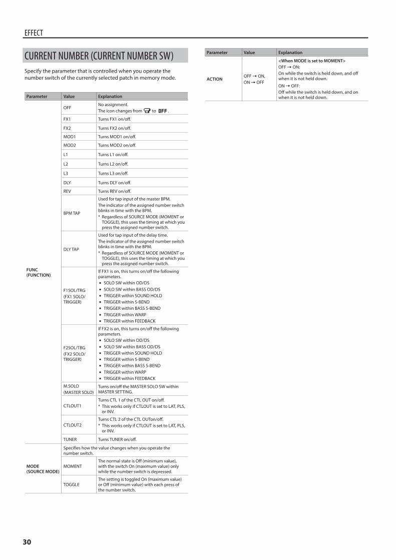
30
EFFECT
CURRENT NUMBER (CURRENT NUMBER SW)Specify the parameter that is controlled when you operate the number switch of the currently selected patch in memory mode.
Parameter Value Explanation
FUNC(FUNCTION)
OFFNo assignment.The icon changes from to .
FX1 Turns FX1 on/off.
FX2 Turns FX2 on/off.
MOD1 Turns MOD1 on/off.
MOD2 Turns MOD2 on/off.
L1 Turns L1 on/off.
L2 Turns L2 on/off.
L3 Turns L3 on/off.
DLY Turns DLY on/off.
REV Turns REV on/off.
BPM TAP
Used for tap input of the master BPM. The indicator of the assigned number switch blinks in time with the BPM.* Regardless of SOURCE MODE (MOMENT or
TOGGLE), this uses the timing at which you press the assigned number switch.
DLY TAP
Used for tap input of the delay time. The indicator of the assigned number switch blinks in time with the BPM.* Regardless of SOURCE MODE (MOMENT or
TOGGLE), this uses the timing at which you press the assigned number switch.
F1SOL/TRG(FX1 SOLO/TRIGGER)
If FX1 is on, this turns on/off the following parameters.
5 SOLO SW within OD/DS 5 SOLO SW within BASS OD/DS 5 TRIGGER within SOUND HOLD 5 TRIGGER within S-BEND 5 TRIGGER within BASS S-BEND 5 TRIGGER within WARP 5 TRIGGER within FEEDBACK
F2SOL/TRG(FX2 SOLO/TRIGGER)
If FX2 is on, this turns on/off the following parameters.
5 SOLO SW within OD/DS 5 SOLO SW within BASS OD/DS 5 TRIGGER within SOUND HOLD 5 TRIGGER within S-BEND 5 TRIGGER within BASS S-BEND 5 TRIGGER within WARP 5 TRIGGER within FEEDBACK
M.SOLO(MASTER SOLO)
Turns on/off the MASTER SOLO SW within MASTER SETTING.
CTLOUT1Turns CTL 1 of the CTL OUT on/off.* This works only if CTLOUT is set to LAT, PLS,
or INV.
CTLOUT2Turns CTL 2 of the CTL OUTon/off.* This works only if CTLOUT is set to LAT, PLS,
or INV.
TUNER Turns TUNER on/off.
MODE(SOURCE MODE)
Specifies how the value changes when you operate the number switch.
MOMENTThe normal state is Off (minimum value), with the switch On (maximum value) only while the number switch is depressed.
TOGGLEThe setting is toggled On (maximum value) or Off (minimum value) with each press of the number switch.
Parameter Value Explanation
ACTIONOFF0ON, ON0OFF
<When MODE is set to MOMENT>OFF0ON:On while the switch is held down, and off when it is not held down.
ON0OFF:Off while the switch is held down, and on when it is not held down.
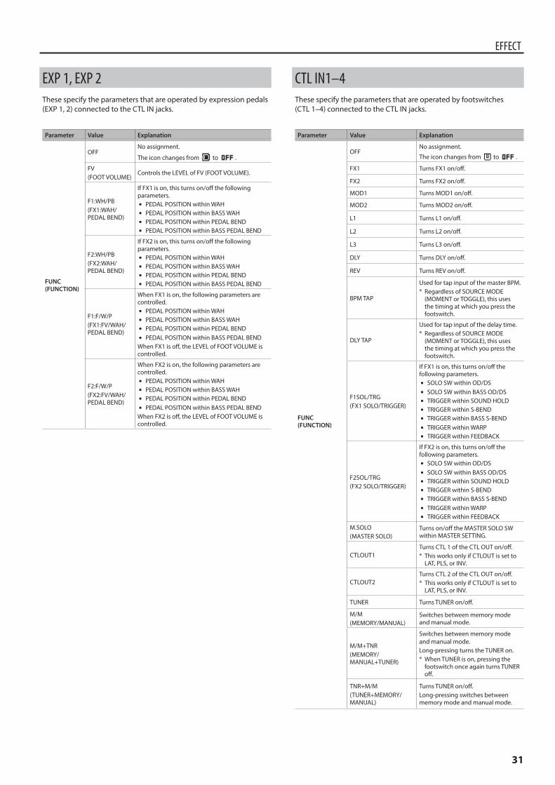
31
EFFECT
EXP 1, EXP 2These specify the parameters that are operated by expression pedals (EXP 1, 2) connected to the CTL IN jacks.
Parameter Value Explanation
FUNC(FUNCTION)
OFFNo assignment.
The icon changes from to .
FV(FOOT VOLUME)
Controls the LEVEL of FV (FOOT VOLUME).
F1:WH/PB(FX1:WAH/PEDAL BEND)
If FX1 is on, this turns on/off the following parameters.
5 PEDAL POSITION within WAH 5 PEDAL POSITION within BASS WAH 5 PEDAL POSITION within PEDAL BEND 5 PEDAL POSITION within BASS PEDAL BEND
F2:WH/PB(FX2:WAH/PEDAL BEND)
If FX2 is on, this turns on/off the following parameters.
5 PEDAL POSITION within WAH 5 PEDAL POSITION within BASS WAH 5 PEDAL POSITION within PEDAL BEND 5 PEDAL POSITION within BASS PEDAL BEND
F1:F/W/P(FX1:FV/WAH/PEDAL BEND)
When FX1 is on, the following parameters are controlled.
5 PEDAL POSITION within WAH 5 PEDAL POSITION within BASS WAH 5 PEDAL POSITION within PEDAL BEND 5 PEDAL POSITION within BASS PEDAL BEND
When FX1 is off, the LEVEL of FOOT VOLUME is controlled.
F2:F/W/P(FX2:FV/WAH/PEDAL BEND)
When FX2 is on, the following parameters are controlled.
5 PEDAL POSITION within WAH 5 PEDAL POSITION within BASS WAH 5 PEDAL POSITION within PEDAL BEND 5 PEDAL POSITION within BASS PEDAL BEND
When FX2 is off, the LEVEL of FOOT VOLUME is controlled.
CTL IN1–4These specify the parameters that are operated by footswitches (CTL 1–4) connected to the CTL IN jacks.
Parameter Value Explanation
FUNC(FUNCTION)
OFFNo assignment.
The icon changes from to .
FX1 Turns FX1 on/off.
FX2 Turns FX2 on/off.
MOD1 Turns MOD1 on/off.
MOD2 Turns MOD2 on/off.
L1 Turns L1 on/off.
L2 Turns L2 on/off.
L3 Turns L3 on/off.
DLY Turns DLY on/off.
REV Turns REV on/off.
BPM TAP
Used for tap input of the master BPM. * Regardless of SOURCE MODE
(MOMENT or TOGGLE), this uses the timing at which you press the footswitch.
DLY TAP
Used for tap input of the delay time. * Regardless of SOURCE MODE
(MOMENT or TOGGLE), this uses the timing at which you press the footswitch.
F1SOL/TRG(FX1 SOLO/TRIGGER)
If FX1 is on, this turns on/off the following parameters.
5 SOLO SW within OD/DS 5 SOLO SW within BASS OD/DS 5 TRIGGER within SOUND HOLD 5 TRIGGER within S-BEND 5 TRIGGER within BASS S-BEND 5 TRIGGER within WARP 5 TRIGGER within FEEDBACK
F2SOL/TRG(FX2 SOLO/TRIGGER)
If FX2 is on, this turns on/off the following parameters.
5 SOLO SW within OD/DS 5 SOLO SW within BASS OD/DS 5 TRIGGER within SOUND HOLD 5 TRIGGER within S-BEND 5 TRIGGER within BASS S-BEND 5 TRIGGER within WARP 5 TRIGGER within FEEDBACK
M.SOLO(MASTER SOLO)
Turns on/off the MASTER SOLO SW within MASTER SETTING.
CTLOUT1Turns CTL 1 of the CTL OUT on/off.* This works only if CTLOUT is set to
LAT, PLS, or INV.
CTLOUT2Turns CTL 2 of the CTL OUT on/off.* This works only if CTLOUT is set to
LAT, PLS, or INV.
TUNER Turns TUNER on/off.
M/M(MEMORY/MANUAL)
Switches between memory mode and manual mode.
M/M+TNR(MEMORY/MANUAL+TUNER)
Switches between memory mode and manual mode.Long-pressing turns the TUNER on.* When TUNER is on, pressing the
footswitch once again turns TUNER off.
TNR+M/M(TUNER+MEMORY/MANUAL)
Turns TUNER on/off.Long-pressing switches between memory mode and manual mode.
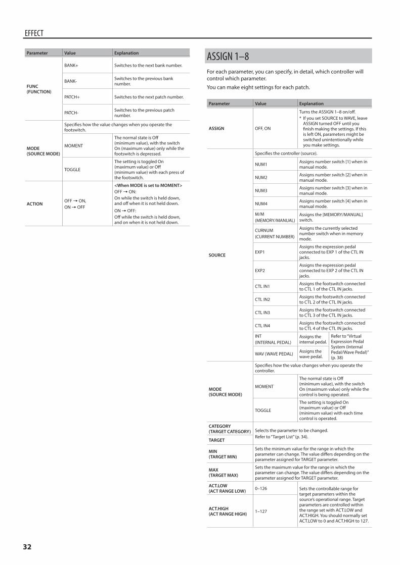
32
EFFECT
Parameter Value Explanation
FUNC(FUNCTION)
BANK+ Switches to the next bank number.
BANK- Switches to the previous bank number.
PATCH+ Switches to the next patch number.
PATCH- Switches to the previous patch number.
MODE(SOURCE MODE)
Specifies how the value changes when you operate the footswitch.
MOMENT
The normal state is Off (minimum value), with the switch On (maximum value) only while the footswitch is depressed.
TOGGLE
The setting is toggled On (maximum value) or Off (minimum value) with each press of the footswitch.
ACTIONOFF0ON, ON0OFF
<When MODE is set to MOMENT>OFF0ON:On while the switch is held down, and off when it is not held down.
ON0OFF:Off while the switch is held down, and on when it is not held down.
ASSIGN 1–8For each parameter, you can specify, in detail, which controller will control which parameter.
You can make eight settings for each patch.
Parameter Value Explanation
ASSIGN OFF, ON
Turns the ASSIGN 1–8 on/off.* If you set SOURCE to WAVE, leave
ASSIGN turned OFF until you finish making the settings. If this is left ON, parameters might be switched unintentionally while you make settings.
SOURCE
Specifies the controller (source).
NUM1 Assigns number switch [1] when in manual mode.
NUM2 Assigns number switch [2] when in manual mode.
NUM3 Assigns number switch [3] when in manual mode.
NUM4 Assigns number switch [4] when in manual mode.
M/M(MEMORY/MANUAL)
Assigns the [MEMORY/MANUAL] switch.
CURNUM(CURRENT NUMBER)
Assigns the currently selected number switch when in memory mode.
EXP1Assigns the expression pedal connected to EXP 1 of the CTL IN jacks.
EXP2Assigns the expression pedal connected to EXP 2 of the CTL IN jacks.
CTL IN1 Assigns the footswitch connected to CTL 1 of the CTL IN jacks.
CTL IN2 Assigns the footswitch connected to CTL 2 of the CTL IN jacks.
CTL IN3 Assigns the footswitch connected to CTL 3 of the CTL IN jacks.
CTL IN4 Assigns the footswitch connected to CTL 4 of the CTL IN jacks.
INT(INTERNAL PEDAL)
Assigns the internal pedal.
Refer to “Virtual Expression Pedal System (Internal Pedal/Wave Pedal)” (p. 38)
WAV (WAVE PEDAL) Assigns the wave pedal.
MODE(SOURCE MODE)
Specifies how the value changes when you operate the controller.
MOMENT
The normal state is Off (minimum value), with the switch On (maximum value) only while the control is being operated.
TOGGLE
The setting is toggled On (maximum value) or Off (minimum value) with each time control is operated.
CATEGORY(TARGET CATEGORY) Selects the parameter to be changed.
Refer to “Target List” (p. 34).TARGET
MIN(TARGET MIN)
Sets the minimum value for the range in which the parameter can change. The value differs depending on the parameter assigned for TARGET parameter.
MAX(TARGET MAX)
Sets the maximum value for the range in which the parameter can change. The value differs depending on the parameter assigned for TARGET parameter.
ACT.LOW(ACT RANGE LOW) 0–126 Sets the controllable range for
target parameters within the source’s operational range. Target parameters are controlled within the range set with ACT.LOW and ACT.HIGH. You should normally set ACT.LOW to 0 and ACT.HIGH to 127.
ACT.HIGH(ACT RANGE HIGH) 1–127
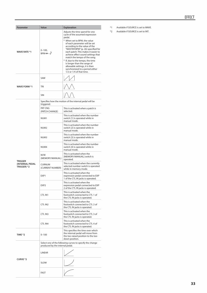
33
EFFECT
Parameter Value Explanation
WAVE RATE *10–100, BPM –
Adjusts the time spend for one cycle of the assumed expression pedal.* When set to BPM, the value
of each parameter will be set according to the value of the “MASTER BPM” (p. 26) specified for each patch. This makes it easier to achieve effect sound settings that match the tempo of the song.
* If, due to the tempo, the time is longer than the range of allowable settings, it is then synchronized to a period either 1/2 or 1/4 of that time.
WAVE FORM *1
SAW
TRI
SIN
TRIGGER(INTERNAL PEDAL TRIGGER) *2
Specifies how the motion of the internal pedal will be triggered.
PAT CNG(PATCH CHANGE)
This is activated when a patch is selected.
NUM1This is activated when the number switch [1] is operated while in manual mode.
NUM2This is activated when the number switch [2] is operated while in manual mode.
NUM3This is activated when the number switch [3] is operated while in manual mode.
NUM4This is activated when the number switch [4] is operated while in manual mode.
M/M(MEMORY/MANUAL)
This is activated when the [MEMORY/MANUAL] switch is operated.
CURNUM(CURRENT NUMBER)
This is activated when the currently selected number switch is operated while in memory mode.
EXP1This is activated when the expression pedal connected to EXP 1 of the CTL IN jacks is operated.
EXP2This is activated when the expression pedal connected to EXP 2 of the CTL IN jacks is operated.
CTL IN1This is activated when the footswitch connected to CTL 1 of the CTL IN jacks is operated.
CTL IN2This is activated when the footswitch connected to CTL 2 of the CTL IN jacks is operated.
CTL IN3This is activated when the footswitch connected to CTL 3 of the CTL IN jacks is operated.
CTL IN4This is activated when the footswitch connected to CTL 4 of the CTL IN jacks is operated.
TIME *2 0–100
This specifies the time over which the internal pedal will move from the toe-raised position to the toe-down position.
CURVE *2
Select one of the following curves to specify the change produced by the internal pedal.
LINEAR
SLOW
FAST
*1 Available if SOURCE is set to WAVE.
*2 Available if SOURCE is set to INT.
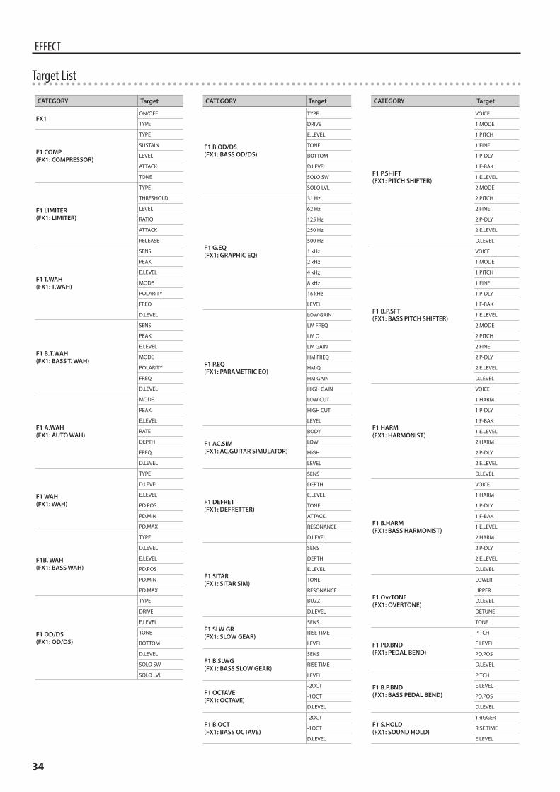
34
EFFECT
CATEGORY Target
FX1ON/OFF
TYPE
F1 COMP(FX1: COMPRESSOR)
TYPE
SUSTAIN
LEVEL
ATTACK
TONE
F1 LIMITER(FX1: LIMITER)
TYPE
THRESHOLD
LEVEL
RATIO
ATTACK
RELEASE
F1 T.WAH(FX1: T.WAH)
SENS
PEAK
E.LEVEL
MODE
POLARITY
FREQ
D.LEVEL
F1 B.T.WAH(FX1: BASS T. WAH)
SENS
PEAK
E.LEVEL
MODE
POLARITY
FREQ
D.LEVEL
F1 A.WAH(FX1: AUTO WAH)
MODE
PEAK
E.LEVEL
RATE
DEPTH
FREQ
D.LEVEL
F1 WAH(FX1: WAH)
TYPE
D.LEVEL
E.LEVEL
PD.POS
PD.MIN
PD.MAX
F1B. WAH(FX1: BASS WAH)
TYPE
D.LEVEL
E.LEVEL
PD.POS
PD.MIN
PD.MAX
F1 OD/DS(FX1: OD/DS)
TYPE
DRIVE
E.LEVEL
TONE
BOTTOM
D.LEVEL
SOLO SW
SOLO LVL
CATEGORY Target
F1 B.OD/DS(FX1: BASS OD/DS)
TYPE
DRIVE
E.LEVEL
TONE
BOTTOM
D.LEVEL
SOLO SW
SOLO LVL
F1 G.EQ(FX1: GRAPHIC EQ)
31 Hz
62 Hz
125 Hz
250 Hz
500 Hz
1 kHz
2 kHz
4 kHz
8 kHz
16 kHz
LEVEL
F1 P.EQ(FX1: PARAMETRIC EQ)
LOW GAIN
LM FREQ
LM Q
LM GAIN
HM FREQ
HM Q
HM GAIN
HIGH GAIN
LOW CUT
HIGH CUT
LEVEL
F1 AC.SIM(FX1: AC.GUITAR SIMULATOR)
BODY
LOW
HIGH
LEVEL
F1 DEFRET(FX1: DEFRETTER)
SENS
DEPTH
E.LEVEL
TONE
ATTACK
RESONANCE
D.LEVEL
F1 SITAR(FX1: SITAR SIM)
SENS
DEPTH
E.LEVEL
TONE
RESONANCE
BUZZ
D.LEVEL
F1 SLW GR(FX1: SLOW GEAR)
SENS
RISE TIME
LEVEL
F1 B.SLWG(FX1: BASS SLOW GEAR)
SENS
RISE TIME
LEVEL
F1 OCTAVE(FX1: OCTAVE)
-2OCT
-1OCT
D.LEVEL
F1 B.OCT(FX1: BASS OCTAVE)
-2OCT
-1OCT
D.LEVEL
CATEGORY Target
F1 P.SHIFT(FX1: PITCH SHIFTER)
VOICE
1:MODE
1:PITCH
1:FINE
1:P-DLY
1:F-BAK
1:E.LEVEL
2:MODE
2:PITCH
2:FINE
2:P-DLY
2:E.LEVEL
D.LEVEL
F1 B.P.SFT(FX1: BASS PITCH SHIFTER)
VOICE
1:MODE
1:PITCH
1:FINE
1:P-DLY
1:F-BAK
1:E.LEVEL
2:MODE
2:PITCH
2:FINE
2:P-DLY
2:E.LEVEL
D.LEVEL
F1 HARM(FX1: HARMONIST)
VOICE
1:HARM
1:P-DLY
1:F-BAK
1:E.LEVEL
2:HARM
2:P-DLY
2:E.LEVEL
D.LEVEL
F1 B.HARM(FX1: BASS HARMONIST)
VOICE
1:HARM
1:P-DLY
1:F-BAK
1:E.LEVEL
2:HARM
2:P-DLY
2:E.LEVEL
D.LEVEL
F1 OvrTONE(FX1: OVERTONE)
LOWER
UPPER
D.LEVEL
DETUNE
TONE
F1 PD.BND(FX1: PEDAL BEND)
PITCH
E.LEVEL
PD.POS
D.LEVEL
F1 B.P.BND(FX1: BASS PEDAL BEND)
PITCH
E.LEVEL
PD.POS
D.LEVEL
F1 S.HOLD(FX1: SOUND HOLD)
TRIGGER
RISE TIME
E.LEVEL
Target List
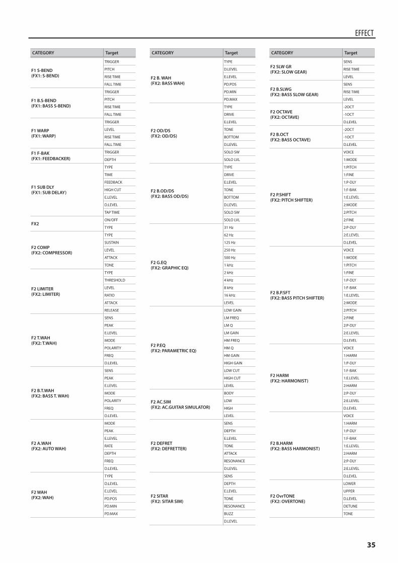
35
EFFECT
CATEGORY Target
F1 S-BEND(FX1: S-BEND)
TRIGGER
PITCH
RISE TIME
FALL TIME
F1 B.S-BEND(FX1: BASS S-BEND)
TRIGGER
PITCH
RISE TIME
FALL TIME
F1 WARP(FX1: WARP)
TRIGGER
LEVEL
RISE TIME
FALL TIME
F1 F-BAK(FX1: FEEDBACKER)
TRIGGER
DEPTH
F1 SUB DLY(FX1: SUB DELAY)
TYPE
TIME
FEEDBACK
HIGH CUT
E.LEVEL
D.LEVEL
TAP TIME
FX2ON/OFF
TYPE
F2 COMP(FX2: COMPRESSOR)
TYPE
SUSTAIN
LEVEL
ATTACK
TONE
F2 LIMITER(FX2: LIMITER)
TYPE
THRESHOLD
LEVEL
RATIO
ATTACK
RELEASE
F2 T.WAH(FX2: T.WAH)
SENS
PEAK
E.LEVEL
MODE
POLARITY
FREQ
D.LEVEL
F2 B.T.WAH(FX2: BASS T. WAH)
SENS
PEAK
E.LEVEL
MODE
POLARITY
FREQ
D.LEVEL
F2 A.WAH(FX2: AUTO WAH)
MODE
PEAK
E.LEVEL
RATE
DEPTH
FREQ
D.LEVEL
F2 WAH(FX2: WAH)
TYPE
D.LEVEL
E.LEVEL
PD.POS
PD.MIN
PD.MAX
CATEGORY Target
F2 B. WAH(FX2: BASS WAH)
TYPE
D.LEVEL
E.LEVEL
PD.POS
PD.MIN
PD.MAX
F2 OD/DS(FX2: OD/DS)
TYPE
DRIVE
E.LEVEL
TONE
BOTTOM
D.LEVEL
SOLO SW
SOLO LVL
F2 B.OD/DS(FX2: BASS OD/DS)
TYPE
DRIVE
E.LEVEL
TONE
BOTTOM
D.LEVEL
SOLO SW
SOLO LVL
F2 G.EQ(FX2: GRAPHIC EQ)
31 Hz
62 Hz
125 Hz
250 Hz
500 Hz
1 kHz
2 kHz
4 kHz
8 kHz
16 kHz
LEVEL
F2 P.EQ(FX2: PARAMETRIC EQ)
LOW GAIN
LM FREQ
LM Q
LM GAIN
HM FREQ
HM Q
HM GAIN
HIGH GAIN
LOW CUT
HIGH CUT
LEVEL
F2 AC.SIM(FX2: AC.GUITAR SIMULATOR)
BODY
LOW
HIGH
LEVEL
F2 DEFRET(FX2: DEFRETTER)
SENS
DEPTH
E.LEVEL
TONE
ATTACK
RESONANCE
D.LEVEL
F2 SITAR(FX2: SITAR SIM)
SENS
DEPTH
E.LEVEL
TONE
RESONANCE
BUZZ
D.LEVEL
CATEGORY Target
F2 SLW GR(FX2: SLOW GEAR)
SENS
RISE TIME
LEVEL
F2 B.SLWG(FX2: BASS SLOW GEAR)
SENS
RISE TIME
LEVEL
F2 OCTAVE(FX2: OCTAVE)
-2OCT
-1OCT
D.LEVEL
F2 B.OCT(FX2: BASS OCTAVE)
-2OCT
-1OCT
D.LEVEL
F2 P.SHIFT(FX2: PITCH SHIFTER)
VOICE
1:MODE
1:PITCH
1:FINE
1:P-DLY
1:F-BAK
1:E.LEVEL
2:MODE
2:PITCH
2:FINE
2:P-DLY
2:E.LEVEL
D.LEVEL
F2 B.P.SFT(FX2: BASS PITCH SHIFTER)
VOICE
1:MODE
1:PITCH
1:FINE
1:P-DLY
1:F-BAK
1:E.LEVEL
2:MODE
2:PITCH
2:FINE
2:P-DLY
2:E.LEVEL
D.LEVEL
F2 HARM(FX2: HARMONIST)
VOICE
1:HARM
1:P-DLY
1:F-BAK
1:E.LEVEL
2:HARM
2:P-DLY
2:E.LEVEL
D.LEVEL
F2 B.HARM(FX2: BASS HARMONIST)
VOICE
1:HARM
1:P-DLY
1:F-BAK
1:E.LEVEL
2:HARM
2:P-DLY
2:E.LEVEL
D.LEVEL
F2 OvrTONE(FX2: OVERTONE)
LOWER
UPPER
D.LEVEL
DETUNE
TONE
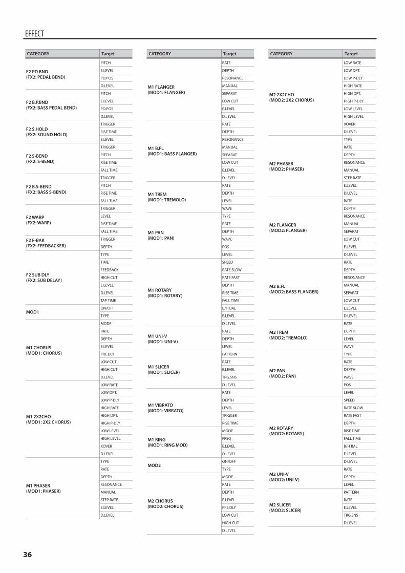
36
EFFECT
CATEGORY Target
F2 PD.BND(FX2: PEDAL BEND)
PITCH
E.LEVEL
PD.POS
D.LEVEL
F2 B.P.BND(FX2: BASS PEDAL BEND)
PITCH
E.LEVEL
PD.POS
D.LEVEL
F2 S.HOLD(FX2: SOUND HOLD)
TRIGGER
RISE TIME
E.LEVEL
F2 S-BEND(FX2: S-BEND)
TRIGGER
PITCH
RISE TIME
FALL TIME
F2 B.S-BEND(FX2: BASS S-BEND)
TRIGGER
PITCH
RISE TIME
FALL TIME
F2 WARP(FX2: WARP)
TRIGGER
LEVEL
RISE TIME
FALL TIME
F2 F-BAK(FX2: FEEDBACKER)
TRIGGER
DEPTH
F2 SUB DLY(FX2: SUB DELAY)
TYPE
TIME
FEEDBACK
HIGH CUT
E.LEVEL
D.LEVEL
TAP TIME
MOD1ON/OFF
TYPE
M1 CHORUS(MOD1: CHORUS)
MODE
RATE
DEPTH
E.LEVEL
PRE.DLY
LOW CUT
HIGH CUT
D.LEVEL
M1 2X2CHO(MOD1: 2X2 CHORUS)
LOW RATE
LOW DPT.
LOW P-DLY
HIGH RATE
HIGH DPT.
HIGH P-DLY
LOW LEVEL
HIGH LEVEL
XOVER
D.LEVEL
M1 PHASER(MOD1: PHASER)
TYPE
RATE
DEPTH
RESONANCE
MANUAL
STEP RATE
E.LEVEL
D.LEVEL
CATEGORY Target
M1 FLANGER(MOD1: FLANGER)
RATE
DEPTH
RESONANCE
MANUAL
SEPARAT
LOW CUT
E.LEVEL
D.LEVEL
M1 B.FL(MOD1: BASS FLANGER)
RATE
DEPTH
RESONANCE
MANUAL
SEPARAT
LOW CUT
E.LEVEL
D.LEVEL
M1 TREM(MOD1: TREMOLO)
RATE
DEPTH
LEVEL
WAVE
M1 PAN(MOD1: PAN)
TYPE
RATE
DEPTH
WAVE
POS
LEVEL
M1 ROTARY(MOD1: ROTARY)
SPEED
RATE SLOW
RATE FAST
DEPTH
RISE TIME
FALL TIME
B/H BAL
E.LEVEL
D.LEVEL
M1 UNI-V(MOD1: UNI-V)
RATE
DEPTH
LEVEL
M1 SLICER(MOD1: SLICER)
PATTERN
RATE
E.LEVEL
TRG.SNS
D.LEVEL
M1 VIBRATO(MOD1: VIBRATO)
RATE
DEPTH
LEVEL
TRIGGER
RISE TIME
M1 RING(MOD1: RING MOD)
MODE
FREQ
E.LEVEL
D.LEVEL
MOD2ON/OFF
TYPE
M2 CHORUS(MOD2: CHORUS)
MODE
RATE
DEPTH
E.LEVEL
PRE.DLY
LOW CUT
HIGH CUT
D.LEVEL
CATEGORY Target
M2 2X2CHO(MOD2: 2X2 CHORUS)
LOW RATE
LOW DPT.
LOW P-DLY
HIGH RATE
HIGH DPT.
HIGH P-DLY
LOW LEVEL
HIGH LEVEL
XOVER
D.LEVEL
M2 PHASER(MOD2: PHASER)
TYPE
RATE
DEPTH
RESONANCE
MANUAL
STEP RATE
E.LEVEL
D.LEVEL
M2 FLANGER(MOD2: FLANGER)
RATE
DEPTH
RESONANCE
MANUAL
SEPARAT
LOW CUT
E.LEVEL
D.LEVEL
M2 B.FL(MOD2: BASS FLANGER)
RATE
DEPTH
RESONANCE
MANUAL
SEPARAT
LOW CUT
E.LEVEL
D.LEVEL
M2 TREM(MOD2: TREMOLO)
RATE
DEPTH
LEVEL
WAVE
M2 PAN(MOD2: PAN)
TYPE
RATE
DEPTH
WAVE
POS
LEVEL
M2 ROTARY(MOD2: ROTARY)
SPEED
RATE SLOW
RATE FAST
DEPTH
RISE TIME
FALL TIME
B/H BAL
E.LEVEL
D.LEVEL
M2 UNI-V(MOD2: UNI-V)
RATE
DEPTH
LEVEL
M2 SLICER(MOD2: SLICER)
PATTERN
RATE
E.LEVEL
TRG.SNS
D.LEVEL
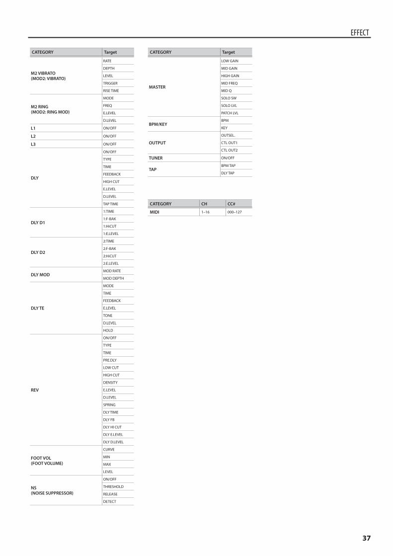
37
EFFECT
CATEGORY Target
M2 VIBRATO(MOD2: VIBRATO)
RATE
DEPTH
LEVEL
TRIGGER
RISE TIME
M2 RING(MOD2: RING MOD)
MODE
FREQ
E.LEVEL
D.LEVEL
L1 ON/OFF
L2 ON/OFF
L3 ON/OFF
DLY
ON/OFF
TYPE
TIME
FEEDBACK
HIGH CUT
E.LEVEL
D.LEVEL
TAP TIME
DLY D1
1:TIME
1:F-BAK
1:HiCUT
1:E.LEVEL
DLY D2
2:TIME
2:F-BAK
2:HiCUT
2:E.LEVEL
DLY MODMOD RATE
MOD DEPTH
DLY TE
MODE
TIME
FEEDBACK
E.LEVEL
TONE
D.LEVEL
HOLD
REV
ON/OFF
TYPE
TIME
PRE.DLY
LOW CUT
HIGH CUT
DENSITY
E.LEVEL
D.LEVEL
SPRING
DLY TIME
DLY FB
DLY HI CUT
DLY E.LEVEL
DLY D.LEVEL
FOOT VOL(FOOT VOLUME)
CURVE
MIN
MAX
LEVEL
NS(NOISE SUPPRESSOR)
ON/OFF
THRESHOLD
RELEASE
DETECT
CATEGORY Target
MASTER
LOW GAIN
MID GAIN
HIGH GAIN
MID FREQ
MID Q
SOLO SW
SOLO LVL
PATCH LVL
BPM/KEYBPM
KEY
OUTPUT
OUTSEL.
CTL OUT1
CTL OUT2
TUNER ON/OFF
TAPBPM TAP
DLY TAP
CATEGORY CH CC#
MIDI 1–16 000–127
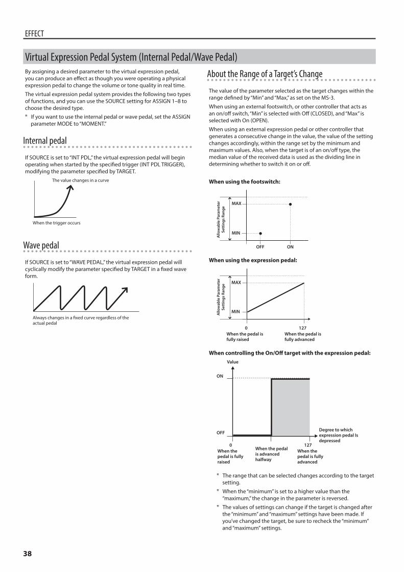
38
EFFECT
By assigning a desired parameter to the virtual expression pedal, you can produce an effect as though you were operating a physical expression pedal to change the volume or tone quality in real time.
The virtual expression pedal system provides the following two types of functions, and you can use the SOURCE setting for ASSIGN 1–8 to choose the desired type.* If you want to use the internal pedal or wave pedal, set the ASSIGN
parameter MODE to “MOMENT.”
Internal pedal
If SOURCE is set to “INT PDL,” the virtual expression pedal will begin operating when started by the specified trigger (INT PDL TRIGGER), modifying the parameter specified by TARGET.
The value changes in a curve
When the trigger occurs
Wave pedal
If SOURCE is set to “WAVE PEDAL,” the virtual expression pedal will cyclically modify the parameter specified by TARGET in a fixed wave form.
Always changes in a fixed curve regardless of the actual pedal
About the Range of a Target’s Change
The value of the parameter selected as the target changes within the range defined by “Min” and “Max,” as set on the MS-3.
When using an external footswitch, or other controller that acts as an on/off switch, “Min” is selected with Off (CLOSED), and “Max” is selected with On (OPEN).
When using an external expression pedal or other controller that generates a consecutive change in the value, the value of the setting changes accordingly, within the range set by the minimum and maximum values. Also, when the target is of an on/off type, the median value of the received data is used as the dividing line in determining whether to switch it on or off.
When using the footswitch:
Allo
wab
le P
aram
eter
Sett
ings
Ran
ge
OFF ON
MAX
MIN
When using the expression pedal:
When the pedal isfully raised
When the pedal isfully advanced
0 127
MAX
MINAllo
wab
le P
aram
eter
Sett
ings
Ran
ge
When controlling the On/Off target with the expression pedal:Value
ON
OFF
When the pedal is fully raised
When the pedal is advanced halfway
When the pedal is fully advanced
Degree to which expression pedal Is depressed
0 127
* The range that can be selected changes according to the target setting.
* When the “minimum” is set to a higher value than the “maximum,” the change in the parameter is reversed.
* The values of settings can change if the target is changed after the “minimum” and “maximum” settings have been made. If you’ve changed the target, be sure to recheck the “minimum” and “maximum” settings.
Virtual Expression Pedal System (Internal Pedal/Wave Pedal)
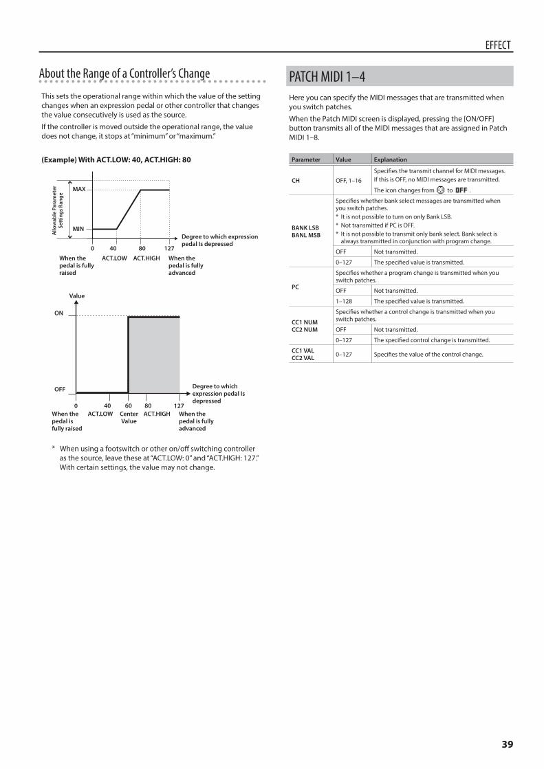
39
EFFECT
About the Range of a Controller’s Change
This sets the operational range within which the value of the setting changes when an expression pedal or other controller that changes the value consecutively is used as the source.
If the controller is moved outside the operational range, the value does not change, it stops at “minimum” or “maximum.”
(Example) With ACT LOW: 40, ACT HIGH: 80
Allo
wab
le P
aram
eter
Sett
ings
Ran
ge
When the pedal is fully raised
ACT.LOW ACT.HIGH When the pedal is fully advanced
Degree to which expression pedal Is depressed
0 12740 80
MAX
MIN
40 8060
Value
ON
OFF Degree to which expression pedal Is depressed
0 127When the pedal is fully raised
ACT.LOW ACT.HIGH When the pedal is fully advanced
CenterValue
* When using a footswitch or other on/off switching controller as the source, leave these at “ACT.LOW: 0” and “ACT.HIGH: 127.” With certain settings, the value may not change.
PATCH MIDI 1–4Here you can specify the MIDI messages that are transmitted when you switch patches.
When the Patch MIDI screen is displayed, pressing the [ON/OFF] button transmits all of the MIDI messages that are assigned in Patch MIDI 1–8.
Parameter Value Explanation
CH OFF, 1–16
Specifies the transmit channel for MIDI messages.If this is OFF, no MIDI messages are transmitted.
The icon changes from to .
BANK LSBBANL MSB
Specifies whether bank select messages are transmitted when you switch patches.* It is not possible to turn on only Bank LSB.* Not transmitted if PC is OFF.* It is not possible to transmit only bank select. Bank select is
always transmitted in conjunction with program change.
OFF Not transmitted.
0–127 The specified value is transmitted.
PC
Specifies whether a program change is transmitted when you switch patches.
OFF Not transmitted.
1–128 The specified value is transmitted.
CC1 NUMCC2 NUM
Specifies whether a control change is transmitted when you switch patches.
OFF Not transmitted.
0–127 The specified control change is transmitted.
CC1 VALCC2 VAL 0–127 Specifies the value of the control change.
40
MENU
DISPLAYHere you can adjust the brightness of the characters in the display.
Parameter Value Explanation
CONTRAST 1–16 Higher values increase the brightness.
GLOBAL (GLOBAL EQ)This adjusts the tone of the OUTPUT regardless of the equalizer on/off settings of individual patches.
Parameter Value Explanation
LOW GAIN -20–+20 dB Adjusts the low frequency range tone.
MID GAIN -20–+20 dB Adjusts the middle frequency range tone.
HIGH GAIN -20–+20 dB Adjusts the high frequency range tone.
MID FREQ(MID FREQUENCY) 20.0 Hz–10.0 kHz
Specifies the center of the frequency range that will be adjusted by the MID GAIN.
MID Q 0.5–16Adjusts the width of the area affected by the EQ centered at the MID FREQ. Higher values will narrow the area.
EQ LVL (EQ LEVEL) -20–+20 dB Adjusts the GLOBAL EQ level.
PLAY (PLAY OPTION)Here you can specify what happens when you operate the pedals or switches while performing, the range of banks that are used, and whether the beat indicator is shown.
Parameter Value Explanation
EXP1 HLD(EXP1 PEDAL HOLD)EXP2 HLD(EXP2 PEDAL HOLD)
OFFWhen you switch patches, the state of FUNCTION operations for EXP 1 and EXP 2 is not applied.
ON
When you switch patches, the state of FUNCTION operations for EXP 1 and EXP 2 is applied if the state is the same as for the previous patch.For example, if the FUNCTION of EXP 1 is FOOT VOLUME for both the previous patch and the newly selected patch, the pedal position at the moment the patch was switched will continue to control the volume after the patch is switched.
SW MODE(SWITCH MODE)
Specifies the timing at which the bank or patch is changed when you operate the switch.* This is valid only for NUM 1–4 in memory mode.
PUSH The change happens when you press the switch.
RELEASE The change happens when you release the switch.
BNK.CNG(BANK CHANGE MODE)
Specifies how patches are switched.
WAIT
Although the indication in the display is updated to reflect the change in the bank, the patch will not change until a number switch has been pressed.
IMMED(IMMEDIATE)
The patch changes immediately when you change banks.
(Example)01-1 0 02-1, 01-3 0 02-3
Parameter Value Explanation
BNK.MIN(BANK EXTENT MIN)BNK.MAX(BANK EXTENT MAX)
(MIN) 01–50(MAX) 01–50
Specify the lower and upper limit of the banks that can be selected. Only the specified range of banks are available for selection.
1+2(press simultaneously NUM1+NUM2)
OFF, BANK DOWN
Specifies whether bank-down occurs when you press number switches [1] and [2] simultaneously.* Valid only in memory mode.
2+3(press simultaneously NUM2+NUM3)
OFF, TUNER
Specifies whether tuner on/off occurs when you press number switches [2] and [3] simultaneously.* Valid only in memory mode.
3+4(press simultaneously NUM3+NUM4)
OFF, BANK UP
Specifies whether bank-up occurs when you press number switches [3] and [4] simultaneously.* Valid only in memory mode.
BEAT LED(BEAT INDICATOR) OFF, ON
If this is ON, the MEMORY/MANUAL indicator blinks in time with the BPM setting.The indicator blinks blue in memory mode, and blinks red in manual mode.
CTLOUT (CTL OUT MODE SETTING)Specifies the operation of the CTL OUT 1/2 jacks.
Parameter Value Explanation
1 MODE(CTL OUT1 MODE)2 MODE(CTL OUT2 MODE)
LAT
(LATCH)Latch operation
PLS (PULSE) Send a pulse when changing patches.
Patch change Patch change
PLS
Patch change Patch change
INVINV (INVERT)
TAP2 Turns on/off twice at the Master BPM setting when the patch changes.
TAP3 Turns on/off three times at the Master BPM setting when the patch changes
TAP4 Turns on/off four times at the Master BPM setting when the patch changes
41
MENU
KNOB (KNOB SETTING)Here you can assign the desired parameters to knobs [1]–[3] in the play screen.* The settings you make here are only for the knobs in the play
screen.
Parameter
KNOB1–KNOB3
Value(Parameter)
Display name Explanation
OFF OFF No assignment.
PATCH PATCH Change patches.
MASTER BPM BPM Changes the MASTER BPM.
MASTER KEY KEY Changes the MASTER KEY.
PATCH LEVEL PATCH LVL Adjusts the patch level.
MASTER EQ LOW GAIN M.EQ:LG Adjusts the MASTER EQ LOW GAIN.
MASTER EQ MID GAIN M.EQ:MG Adjusts the MASTER EQ MID GAIN.
MASTER EQ MID FREQUENCY M.EQ:MF Adjusts the MASTER EQ MID FREQUENCY.
MASTER EQ MID Q M.EQ:MQ Adjusts the MASTER EQ MID Q.
MASTER EQ HIGH GAIN M.EQ:HG Adjusts the MASTER EQ HIGH GAIN.
MASTER SOLO SW M.SOLO SW Switches the MASTER SOLO SW on/off.
MASTER SOLO LEVEL M.SOLO LVL Adjusts the volume when master solo is on.
OUTPUT SELECT OUTSEL. Switches the output setting of the OUTPUT L/MONO jack and R jack.
CTLOUT1 CTLOUT1
Changes the control signal setting for CTL 1 of the CTL OUT jack.The control signal that can be selected depends on the CTL OUT MODE SETTING in MENU.
CTLOUT2 CTLOUT2
Changes the control signal setting for CTL 2 of the CTL OUT jack.The control signal that can be selected depends on the CTL OUT MODE SETTING in MENU.
GLOBAL EQ LOW GAIN G.EQ:LG Adjusts the GLOBAL EQ LOW GAIN.
GLOBAL EQ MID GAIN G.EQ:MG Adjusts the GOBAL EQ MID GAIN.
GLOBAL EQ MID FREQUENCY G.EQ:MF Adjusts the GLOBAL EQ MID FREQUENCY.
GLOBAL EQ MID Q G.EQ:MQ Adjusts the GLOBAL EQ MID Q.
GLOBAL EQ HIGH GAIN G.EQ:HG Adjusts the GLOBAL EQ HIGH GAIN.
GLOBAL EQ LEVEL G.EQ:LVL Adjusts the GLOBAL EQ LEVEL.
FOOT VOLUME LEVEL FV:LVL Adjusts the FOOT VOLUME LEVEL.
BEAT INDICATOR BEAT LED Switches the BEAT INDICATOR on/off.
MEMORY/MANUAL M/M Switches between memory mode and manual mode.
MIDI (MIDI SETTING)Specifies whether MIDI clock messages are transmitted from the MIDI OUT connector.
Parameter Value
CLK OUT (CLOCK OUT) OFF, ON
PREF (PREFERENCE)Here you can specify whether the settings for the switches, external footswitches, and external expression pedals of the MS-3, and the OUTPUT SELECT and BPM settings, will use separate settings for each patch, or whether the same settings will be shared by all patches.
Parameter Value Explanation
NUM1(NUMBER 1 SW)
PATCH, SYSTEM
Operation of number switch [1] in manual mode
NUM2(NUMBER 2 SW)
Operation of number switch [2] in manual mode
NUM3(NUMBER 3 SW)
Operation of number switch [3] in manual mode
NUM4(NUMBER 4 SW)
Operation of number switch [4] in manual mode
M/M(MEMORY/MANUAL SW) Operation of [MEMORY/MANUAL] switch
CURNUM(CURRENT NUMBER SW)
Operation when the currently selected number switch is operated in memory mode(Example)Operation of number switch [1] when 01-1 is selected
EXP1Operation when the expression pedal connected to EXP 1 of the CTL IN jacks is operated
EXP2Operation when the expression pedal connected to EXP 2 of the CTL IN jacks is operated
CTLIN1Operation when the expression pedal connected to CTL 1 of the CTL IN jacks is operated
CTLIN2Operation when the expression pedal connected to CTL 2 of the CTL IN jacks is operated
CTLIN3Operation when the expression pedal connected to CTL 3 of the CTL IN jacks is operated
CTLIN4Operation when the expression pedal connected to CTL 4 of the CTL IN jacks is operated
OUTPUTSEL(OUTPUT SELECT)
How sound is output from the OUTPUT L/MONO jack and R jack
BPM MASTER BPM
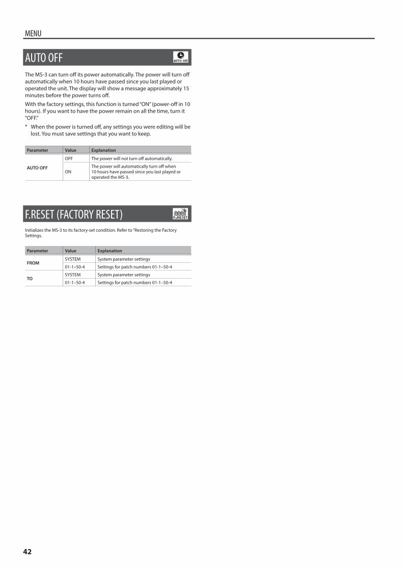
42
MENU
AUTO OFFThe MS-3 can turn off its power automatically. The power will turn off automatically when 10 hours have passed since you last played or operated the unit. The display will show a message approximately 15 minutes before the power turns off.
With the factory settings, this function is turned “ON” (power-off in 10 hours). If you want to have the power remain on all the time, turn it “OFF.”* When the power is turned off, any settings you were editing will be
lost. You must save settings that you want to keep.
Parameter Value Explanation
AUTO OFF
OFF The power will not turn off automatically.
ONThe power will automatically turn off when 10 hours have passed since you last played or operated the MS-3.
F.RESET (FACTORY RESET)Initializes the MS-3 to its factory-set condition. Refer to “Restoring the Factory Settings.
Parameter Value Explanation
FROMSYSTEM System parameter settings
01-1–50-4 Settings for patch numbers 01-1–50-4
TOSYSTEM System parameter settings
01-1–50-4 Settings for patch numbers 01-1–50-4
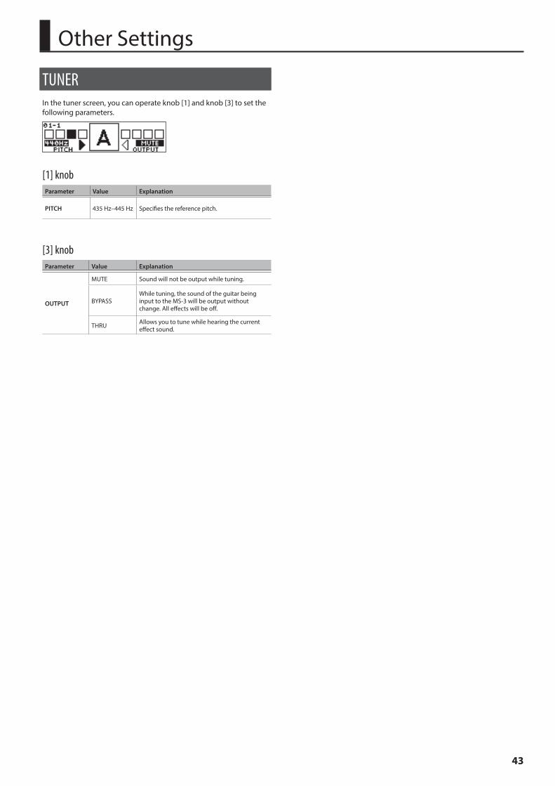
43
Other Settings
TUNERIn the tuner screen, you can operate knob [1] and knob [3] to set the following parameters.
[1] knobParameter Value Explanation
PITCH 435 Hz–445 Hz Specifies the reference pitch.
[3] knobParameter Value Explanation
OUTPUT
MUTE Sound will not be output while tuning.
BYPASSWhile tuning, the sound of the guitar being input to the MS-3 will be output without change. All effects will be off.
THRU Allows you to tune while hearing the current effect sound.
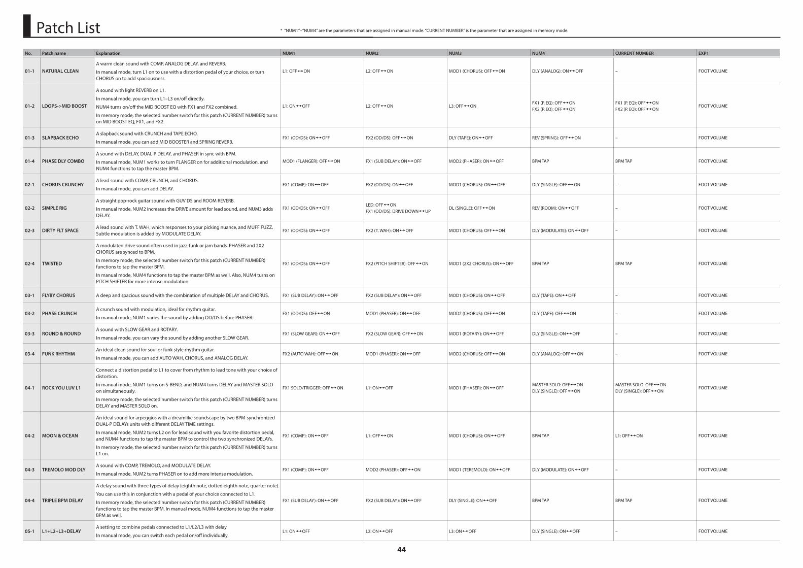
44
No. Patch name Explanation NUM1 NUM2 NUM3 NUM4 CURRENT NUMBER EXP1
01-1 NATURAL CLEANA warm clean sound with COMP, ANALOG DELAY, and REVERB.
In manual mode, turn L1 on to use with a distortion pedal of your choice, or turn CHORUS on to add spaciousness.
L1: OFF,ON L2: OFF,ON MOD1 (CHORUS): OFF,ON DLY (ANALOG): ON,OFF – FOOT VOLUME
01-2 LOOPS->MID BOOST
A sound with light REVERB on L1.
In manual mode, you can turn L1–L3 on/off directly.
NUM4 turns on/off the MID BOOST EQ with FX1 and FX2 combined.
In memory mode, the selected number switch for this patch (CURRENT NUMBER) turns on MID BOOST EQ, FX1, and FX2.
L1: ON,OFF L2: OFF,ON L3: OFF,ONFX1 (P. EQ): OFF,ONFX2 (P. EQ): OFF,ON
FX1 (P. EQ): OFF,ONFX2 (P. EQ): OFF,ON
FOOT VOLUME
01-3 SLAPBACK ECHOA slapback sound with CRUNCH and TAPE ECHO.
In manual mode, you can add MID BOOSTER and SPRING REVERB.FX1 (OD/DS): ON,OFF FX2 (OD/DS): OFF,ON DLY (TAPE): ON,OFF REV (SPRING): OFF,ON – FOOT VOLUME
01-4 PHASE DLY COMBOA sound with DELAY, DUAL-P DELAY, and PHASER in sync with BPM.
In manual mode, NUM1 works to turn FLANGER on for additional modulation, and NUM4 functions to tap the master BPM.
MOD1 (FLANGER): OFF,ON FX1 (SUB DELAY): ON,OFF MOD2 (PHASER): ON,OFF BPM TAP BPM TAP FOOT VOLUME
02-1 CHORUS CRUNCHYA lead sound with COMP, CRUNCH, and CHORUS.
In manual mode, you can add DELAY.FX1 (COMP): ON,OFF FX2 (OD/DS): ON,OFF MOD1 (CHORUS): ON,OFF DLY (SINGLE): OFF,ON – FOOT VOLUME
02-2 SIMPLE RIGA straight pop-rock guitar sound with GUV DS and ROOM REVERB.
In manual mode, NUM2 increases the DRIVE amount for lead sound, and NUM3 adds DELAY.
FX1 (OD/DS): ON,OFFLED: OFF,ONFX1 (OD/DS): DRIVE DOWN,UP
DL (SINGLE): OFF,ON REV (ROOM): ON,OFF – FOOT VOLUME
02-3 DIRTY FLT SPACEA lead sound with T. WAH, which responses to your picking nuance, and MUFF FUZZ. Subtle modulation is added by MODULATE DELAY.
FX1 (OD/DS): ON,OFF FX2 (T. WAH): ON,OFF MOD1 (CHORUS): OFF,ON DLY (MODULATE): ON,OFF – FOOT VOLUME
02-4 TWISTED
A modulated drive sound often used in jazz-funk or jam bands. PHASER and 2X2 CHORUS are synced to BPM.
In memory mode, the selected number switch for this patch (CURRENT NUMBER) functions to tap the master BPM.
In manual mode, NUM4 functions to tap the master BPM as well. Also, NUM4 turns on PITCH SHIFTER for more intense modulation.
FX1 (OD/DS): ON,OFF FX2 (PITCH SHIFTER): OFF,ON MOD1 (2X2 CHORUS): ON,OFF BPM TAP BPM TAP FOOT VOLUME
03-1 FLYBY CHORUS A deep and spacious sound with the combination of multiple DELAY and CHORUS. FX1 (SUB DELAY): ON,OFF FX2 (SUB DELAY): ON,OFF MOD1 (CHORUS): ON,OFF DLY (TAPE): ON,OFF – FOOT VOLUME
03-2 PHASE CRUNCHA crunch sound with modulation, ideal for rhythm guitar.
In manual mode, NUM1 varies the sound by adding OD/DS before PHASER.FX1 (OD/DS): OFF,ON MOD1 (PHASER): ON,OFF MOD2 (CHORUS): OFF,ON DLY (TAPE): OFF,ON – FOOT VOLUME
03-3 ROUND & ROUNDA sound with SLOW GEAR and ROTARY.
In manual mode, you can vary the sound by adding another SLOW GEAR.FX1 (SLOW GEAR): ON,OFF FX2 (SLOW GEAR): OFF,ON MOD1 (ROTARY): ON,OFF DLY (SINGLE): ON,OFF – FOOT VOLUME
03-4 FUNK RHYTHMAn ideal clean sound for soul or funk style rhythm guitar.
In manual mode, you can add AUTO WAH, CHORUS, and ANALOG DELAY.FX2 (AUTO WAH): OFF,ON MOD1 (PHASER): ON,OFF MOD2 (CHORUS): OFF,ON DLY (ANALOG): OFF,ON – FOOT VOLUME
04-1 ROCK YOU LUV L1
Connect a distortion pedal to L1 to cover from rhythm to lead tone with your choice of distortion.
In manual mode, NUM1 turns on S-BEND, and NUM4 turns DELAY and MASTER SOLO on simultaneously.
In memory mode, the selected number switch for this patch (CURRENT NUMBER) turns DELAY and MASTER SOLO on.
FX1 SOLO/TRIGGER: OFF,ON L1: ON,OFF MOD1 (PHASER): ON,OFFMASTER SOLO: OFF,ONDLY (SINGLE): OFF,ON
MASTER SOLO: OFF,ONDLY (SINGLE): OFF,ON
FOOT VOLUME
04-2 MOON & OCEAN
An ideal sound for arpeggios with a dreamlike soundscape by two BPM-synchronized DUAL-P DELAYs units with different DELAY TIME settings.
In manual mode, NUM2 turns L2 on for lead sound with you favorite distortion pedal, and NUM4 functions to tap the master BPM to control the two synchronized DELAYs.
In memory mode, the selected number switch for this patch (CURRENT NUMBER) turns L1 on.
FX1 (COMP): ON,OFF L1: OFF,ON MOD1 (CHORUS): ON,OFF BPM TAP L1: OFF,ON FOOT VOLUME
04-3 TREMOLO MOD DLYA sound with COMP, TREMOLO, and MODULATE DELAY.
In manual mode, NUM2 turns PHASER on to add more intense modulation.FX1 (COMP): ON,OFF MOD2 (PHASER): OFF,ON MOD1 (TEREMOLO): ON,OFF DLY (MODULATE): ON,OFF – FOOT VOLUME
04-4 TRIPLE BPM DELAY
A delay sound with three types of delay (eighth note, dotted eighth note, quarter note).
You can use this in conjunction with a pedal of your choice connected to L1.
In memory mode, the selected number switch for this patch (CURRENT NUMBER) functions to tap the master BPM. In manual mode, NUM4 functions to tap the master BPM as well.
FX1 (SUB DELAY): ON,OFF FX2 (SUB DELAY): ON,OFF DLY (SINGLE): ON,OFF BPM TAP BPM TAP FOOT VOLUME
05-1 L1+L2+L3+DELAYA setting to combine pedals connected to L1/L2/L3 with delay.
In manual mode, you can switch each pedal on/off individually.L1: ON,OFF L2: ON,OFF L3: ON,OFF DLY (SINGLE): ON,OFF – FOOT VOLUME
Patch List * “NUM1”–“NUM4” are the parameters that are assigned in manual mode. “CURRENT NUMBER” is the parameter that are assigned in memory mode.
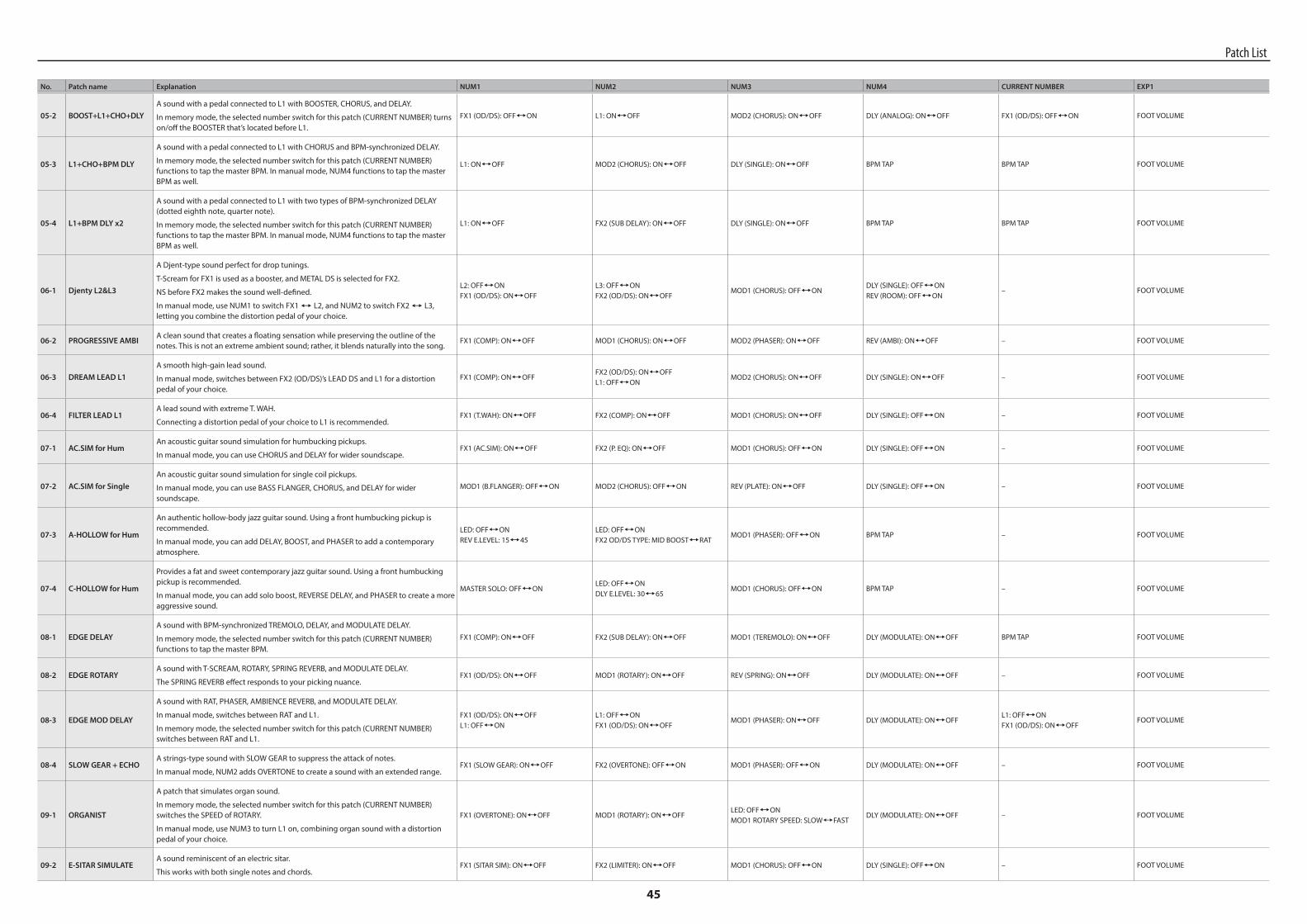
45
No. Patch name Explanation NUM1 NUM2 NUM3 NUM4 CURRENT NUMBER EXP1
05-2 BOOST+L1+CHO+DLYA sound with a pedal connected to L1 with BOOSTER, CHORUS, and DELAY.
In memory mode, the selected number switch for this patch (CURRENT NUMBER) turns on/off the BOOSTER that’s located before L1.
FX1 (OD/DS): OFF,ON L1: ON,OFF MOD2 (CHORUS): ON,OFF DLY (ANALOG): ON,OFF FX1 (OD/DS): OFF,ON FOOT VOLUME
05-3 L1+CHO+BPM DLY
A sound with a pedal connected to L1 with CHORUS and BPM-synchronized DELAY.
In memory mode, the selected number switch for this patch (CURRENT NUMBER) functions to tap the master BPM. In manual mode, NUM4 functions to tap the master BPM as well.
L1: ON,OFF MOD2 (CHORUS): ON,OFF DLY (SINGLE): ON,OFF BPM TAP BPM TAP FOOT VOLUME
05-4 L1+BPM DLY x2
A sound with a pedal connected to L1 with two types of BPM-synchronized DELAY (dotted eighth note, quarter note).
In memory mode, the selected number switch for this patch (CURRENT NUMBER) functions to tap the master BPM. In manual mode, NUM4 functions to tap the master BPM as well.
L1: ON,OFF FX2 (SUB DELAY): ON,OFF DLY (SINGLE): ON,OFF BPM TAP BPM TAP FOOT VOLUME
06-1 Djenty L2&L3
A Djent-type sound perfect for drop tunings.
T-Scream for FX1 is used as a booster, and METAL DS is selected for FX2.
NS before FX2 makes the sound well-defined.
In manual mode, use NUM1 to switch FX1 , L2, and NUM2 to switch FX2 , L3, letting you combine the distortion pedal of your choice.
L2: OFF,ONFX1 (OD/DS): ON,OFF
L3: OFF,ONFX2 (OD/DS): ON,OFF
MOD1 (CHORUS): OFF,ONDLY (SINGLE): OFF,ONREV (ROOM): OFF,ON
– FOOT VOLUME
06-2 PROGRESSIVE AMBIA clean sound that creates a floating sensation while preserving the outline of the notes. This is not an extreme ambient sound; rather, it blends naturally into the song.
FX1 (COMP): ON,OFF MOD1 (CHORUS): ON,OFF MOD2 (PHASER): ON,OFF REV (AMBI): ON,OFF – FOOT VOLUME
06-3 DREAM LEAD L1A smooth high-gain lead sound.
In manual mode, switches between FX2 (OD/DS)’s LEAD DS and L1 for a distortion pedal of your choice.
FX1 (COMP): ON,OFFFX2 (OD/DS): ON,OFFL1: OFF,ON
MOD2 (CHORUS): ON,OFF DLY (SINGLE): ON,OFF – FOOT VOLUME
06-4 FILTER LEAD L1A lead sound with extreme T. WAH.
Connecting a distortion pedal of your choice to L1 is recommended.FX1 (T.WAH): ON,OFF FX2 (COMP): ON,OFF MOD1 (CHORUS): ON,OFF DLY (SINGLE): OFF,ON – FOOT VOLUME
07-1 AC.SIM for HumAn acoustic guitar sound simulation for humbucking pickups.
In manual mode, you can use CHORUS and DELAY for wider soundscape.FX1 (AC.SIM): ON,OFF FX2 (P. EQ): ON,OFF MOD1 (CHORUS): OFF,ON DLY (SINGLE): OFF,ON – FOOT VOLUME
07-2 AC.SIM for SingleAn acoustic guitar sound simulation for single coil pickups.
In manual mode, you can use BASS FLANGER, CHORUS, and DELAY for wider soundscape.
MOD1 (B.FLANGER): OFF,ON MOD2 (CHORUS): OFF,ON REV (PLATE): ON,OFF DLY (SINGLE): OFF,ON – FOOT VOLUME
07-3 A-HOLLOW for Hum
An authentic hollow-body jazz guitar sound. Using a front humbucking pickup is recommended.
In manual mode, you can add DELAY, BOOST, and PHASER to add a contemporary atmosphere.
LED: OFF,ONREV E.LEVEL: 15,45
LED: OFF,ONFX2 OD/DS TYPE: MID BOOST,RAT
MOD1 (PHASER): OFF,ON BPM TAP – FOOT VOLUME
07-4 C-HOLLOW for Hum
Provides a fat and sweet contemporary jazz guitar sound. Using a front humbucking pickup is recommended.
In manual mode, you can add solo boost, REVERSE DELAY, and PHASER to create a more aggressive sound.
MASTER SOLO: OFF,ONLED: OFF,ONDLY E.LEVEL: 30,65
MOD1 (CHORUS): OFF,ON BPM TAP – FOOT VOLUME
08-1 EDGE DELAYA sound with BPM-synchronized TREMOLO, DELAY, and MODULATE DELAY.
In memory mode, the selected number switch for this patch (CURRENT NUMBER) functions to tap the master BPM.
FX1 (COMP): ON,OFF FX2 (SUB DELAY): ON,OFF MOD1 (TEREMOLO): ON,OFF DLY (MODULATE): ON,OFF BPM TAP FOOT VOLUME
08-2 EDGE ROTARYA sound with T-SCREAM, ROTARY, SPRING REVERB, and MODULATE DELAY.
The SPRING REVERB effect responds to your picking nuance.FX1 (OD/DS): ON,OFF MOD1 (ROTARY): ON,OFF REV (SPRING): ON,OFF DLY (MODULATE): ON,OFF – FOOT VOLUME
08-3 EDGE MOD DELAY
A sound with RAT, PHASER, AMBIENCE REVERB, and MODULATE DELAY.
In manual mode, switches between RAT and L1.
In memory mode, the selected number switch for this patch (CURRENT NUMBER) switches between RAT and L1.
FX1 (OD/DS): ON,OFFL1: OFF,ON
L1: OFF,ONFX1 (OD/DS): ON,OFF
MOD1 (PHASER): ON,OFF DLY (MODULATE): ON,OFFL1: OFF,ONFX1 (OD/DS): ON,OFF
FOOT VOLUME
08-4 SLOW GEAR + ECHOA strings-type sound with SLOW GEAR to suppress the attack of notes.
In manual mode, NUM2 adds OVERTONE to create a sound with an extended range.FX1 (SLOW GEAR): ON,OFF FX2 (OVERTONE): OFF,ON MOD1 (PHASER): OFF,ON DLY (MODULATE): ON,OFF – FOOT VOLUME
09-1 ORGANIST
A patch that simulates organ sound.
In memory mode, the selected number switch for this patch (CURRENT NUMBER) switches the SPEED of ROTARY.
In manual mode, use NUM3 to turn L1 on, combining organ sound with a distortion pedal of your choice.
FX1 (OVERTONE): ON,OFF MOD1 (ROTARY): ON,OFFLED: OFF,ONMOD1 ROTARY SPEED: SLOW,FAST
DLY (MODULATE): ON,OFF – FOOT VOLUME
09-2 E-SITAR SIMULATEA sound reminiscent of an electric sitar.
This works with both single notes and chords.FX1 (SITAR SIM): ON,OFF FX2 (LIMITER): ON,OFF MOD1 (CHORUS): OFF,ON DLY (SINGLE): OFF,ON – FOOT VOLUME
Patch List
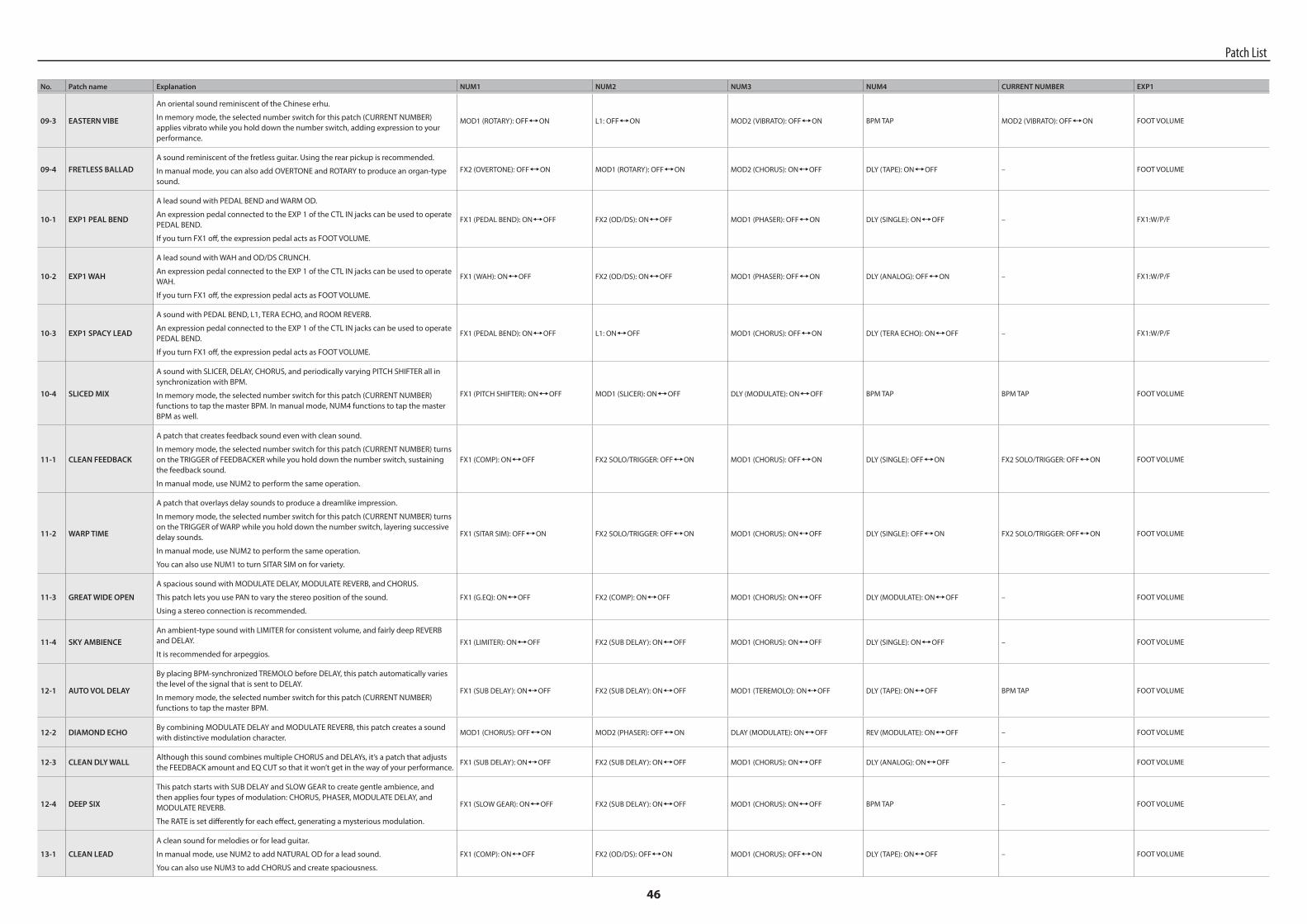
46
No. Patch name Explanation NUM1 NUM2 NUM3 NUM4 CURRENT NUMBER EXP1
09-3 EASTERN VIBE
An oriental sound reminiscent of the Chinese erhu.
In memory mode, the selected number switch for this patch (CURRENT NUMBER) applies vibrato while you hold down the number switch, adding expression to your performance.
MOD1 (ROTARY): OFF,ON L1: OFF,ON MOD2 (VIBRATO): OFF,ON BPM TAP MOD2 (VIBRATO): OFF,ON FOOT VOLUME
09-4 FRETLESS BALLADA sound reminiscent of the fretless guitar. Using the rear pickup is recommended.
In manual mode, you can also add OVERTONE and ROTARY to produce an organ-type sound.
FX2 (OVERTONE): OFF,ON MOD1 (ROTARY): OFF,ON MOD2 (CHORUS): ON,OFF DLY (TAPE): ON,OFF – FOOT VOLUME
10-1 EXP1 PEAL BEND
A lead sound with PEDAL BEND and WARM OD.
An expression pedal connected to the EXP 1 of the CTL IN jacks can be used to operate PEDAL BEND.
If you turn FX1 off, the expression pedal acts as FOOT VOLUME.
FX1 (PEDAL BEND): ON,OFF FX2 (OD/DS): ON,OFF MOD1 (PHASER): OFF,ON DLY (SINGLE): ON,OFF – FX1:W/P/F
10-2 EXP1 WAH
A lead sound with WAH and OD/DS CRUNCH.
An expression pedal connected to the EXP 1 of the CTL IN jacks can be used to operate WAH.
If you turn FX1 off, the expression pedal acts as FOOT VOLUME.
FX1 (WAH): ON,OFF FX2 (OD/DS): ON,OFF MOD1 (PHASER): OFF,ON DLY (ANALOG): OFF,ON – FX1:W/P/F
10-3 EXP1 SPACY LEAD
A sound with PEDAL BEND, L1, TERA ECHO, and ROOM REVERB.
An expression pedal connected to the EXP 1 of the CTL IN jacks can be used to operate PEDAL BEND.
If you turn FX1 off, the expression pedal acts as FOOT VOLUME.
FX1 (PEDAL BEND): ON,OFF L1: ON,OFF MOD1 (CHORUS): OFF,ON DLY (TERA ECHO): ON,OFF – FX1:W/P/F
10-4 SLICED MIX
A sound with SLICER, DELAY, CHORUS, and periodically varying PITCH SHIFTER all in synchronization with BPM.
In memory mode, the selected number switch for this patch (CURRENT NUMBER) functions to tap the master BPM. In manual mode, NUM4 functions to tap the master BPM as well.
FX1 (PITCH SHIFTER): ON,OFF MOD1 (SLICER): ON,OFF DLY (MODULATE): ON,OFF BPM TAP BPM TAP FOOT VOLUME
11-1 CLEAN FEEDBACK
A patch that creates feedback sound even with clean sound.
In memory mode, the selected number switch for this patch (CURRENT NUMBER) turns on the TRIGGER of FEEDBACKER while you hold down the number switch, sustaining the feedback sound.
In manual mode, use NUM2 to perform the same operation.
FX1 (COMP): ON,OFF FX2 SOLO/TRIGGER: OFF,ON MOD1 (CHORUS): OFF,ON DLY (SINGLE): OFF,ON FX2 SOLO/TRIGGER: OFF,ON FOOT VOLUME
11-2 WARP TIME
A patch that overlays delay sounds to produce a dreamlike impression.
In memory mode, the selected number switch for this patch (CURRENT NUMBER) turns on the TRIGGER of WARP while you hold down the number switch, layering successive delay sounds.
In manual mode, use NUM2 to perform the same operation.
You can also use NUM1 to turn SITAR SIM on for variety.
FX1 (SITAR SIM): OFF,ON FX2 SOLO/TRIGGER: OFF,ON MOD1 (CHORUS): ON,OFF DLY (SINGLE): OFF,ON FX2 SOLO/TRIGGER: OFF,ON FOOT VOLUME
11-3 GREAT WIDE OPEN
A spacious sound with MODULATE DELAY, MODULATE REVERB, and CHORUS.
This patch lets you use PAN to vary the stereo position of the sound.
Using a stereo connection is recommended.
FX1 (G.EQ): ON,OFF FX2 (COMP): ON,OFF MOD1 (CHORUS): ON,OFF DLY (MODULATE): ON,OFF – FOOT VOLUME
11-4 SKY AMBIENCEAn ambient-type sound with LIMITER for consistent volume, and fairly deep REVERB and DELAY.
It is recommended for arpeggios.FX1 (LIMITER): ON,OFF FX2 (SUB DELAY): ON,OFF MOD1 (CHORUS): ON,OFF DLY (SINGLE): ON,OFF – FOOT VOLUME
12-1 AUTO VOL DELAY
By placing BPM-synchronized TREMOLO before DELAY, this patch automatically varies the level of the signal that is sent to DELAY.
In memory mode, the selected number switch for this patch (CURRENT NUMBER) functions to tap the master BPM.
FX1 (SUB DELAY): ON,OFF FX2 (SUB DELAY): ON,OFF MOD1 (TEREMOLO): ON,OFF DLY (TAPE): ON,OFF BPM TAP FOOT VOLUME
12-2 DIAMOND ECHOBy combining MODULATE DELAY and MODULATE REVERB, this patch creates a sound with distinctive modulation character.
MOD1 (CHORUS): OFF,ON MOD2 (PHASER): OFF,ON DLAY (MODULATE): ON,OFF REV (MODULATE): ON,OFF – FOOT VOLUME
12-3 CLEAN DLY WALLAlthough this sound combines multiple CHORUS and DELAYs, it’s a patch that adjusts the FEEDBACK amount and EQ CUT so that it won’t get in the way of your performance.
FX1 (SUB DELAY): ON,OFF FX2 (SUB DELAY): ON,OFF MOD1 (CHORUS): ON,OFF DLY (ANALOG): ON,OFF – FOOT VOLUME
12-4 DEEP SIX
This patch starts with SUB DELAY and SLOW GEAR to create gentle ambience, and then applies four types of modulation: CHORUS, PHASER, MODULATE DELAY, and MODULATE REVERB.
The RATE is set differently for each effect, generating a mysterious modulation.
FX1 (SLOW GEAR): ON,OFF FX2 (SUB DELAY): ON,OFF MOD1 (CHORUS): ON,OFF BPM TAP – FOOT VOLUME
13-1 CLEAN LEAD
A clean sound for melodies or for lead guitar.
In manual mode, use NUM2 to add NATURAL OD for a lead sound.
You can also use NUM3 to add CHORUS and create spaciousness.
FX1 (COMP): ON,OFF FX2 (OD/DS): OFF,ON MOD1 (CHORUS): OFF,ON DLY (TAPE): ON,OFF – FOOT VOLUME
Patch List
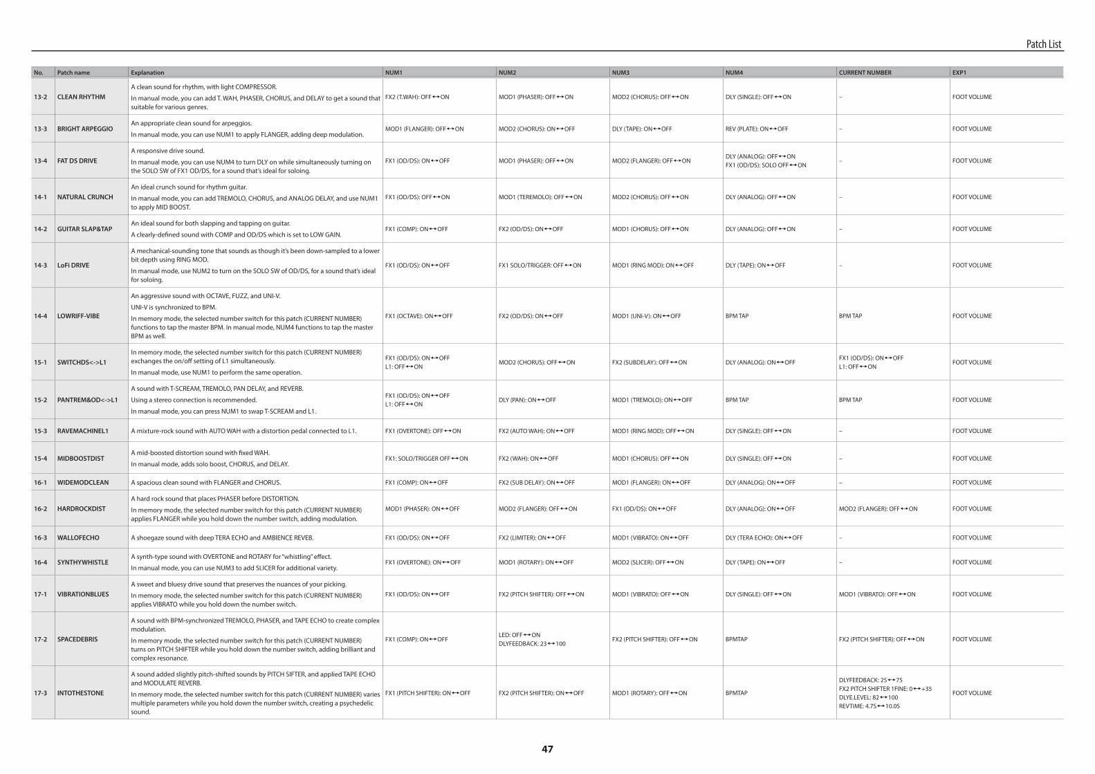
47
No. Patch name Explanation NUM1 NUM2 NUM3 NUM4 CURRENT NUMBER EXP1
13-2 CLEAN RHYTHMA clean sound for rhythm, with light COMPRESSOR.
In manual mode, you can add T. WAH, PHASER, CHORUS, and DELAY to get a sound that suitable for various genres.
FX2 (T.WAH): OFF,ON MOD1 (PHASER): OFF,ON MOD2 (CHORUS): OFF,ON DLY (SINGLE): OFF,ON – FOOT VOLUME
13-3 BRIGHT ARPEGGIOAn appropriate clean sound for arpeggios.
In manual mode, you can use NUM1 to apply FLANGER, adding deep modulation.MOD1 (FLANGER): OFF,ON MOD2 (CHORUS): ON,OFF DLY (TAPE): ON,OFF REV (PLATE): ON,OFF – FOOT VOLUME
13-4 FAT DS DRIVEA responsive drive sound.
In manual mode, you can use NUM4 to turn DLY on while simultaneously turning on the SOLO SW of FX1 OD/DS, for a sound that’s ideal for soloing.
FX1 (OD/DS): ON,OFF MOD1 (PHASER): OFF,ON MOD2 (FLANGER): OFF,ONDLY (ANALOG): OFF,ONFX1 (OD/DS): SOLO OFF,ON
– FOOT VOLUME
14-1 NATURAL CRUNCHAn ideal crunch sound for rhythm guitar.
In manual mode, you can add TREMOLO, CHORUS, and ANALOG DELAY, and use NUM1 to apply MID BOOST.
FX1 (OD/DS): OFF,ON MOD1 (TEREMOLO): OFF,ON MOD2 (CHORUS): OFF,ON DLY (ANALOG): OFF,ON – FOOT VOLUME
14-2 GUITAR SLAP&TAPAn ideal sound for both slapping and tapping on guitar.
A clearly-defined sound with COMP and OD/DS which is set to LOW GAIN.FX1 (COMP): ON,OFF FX2 (OD/DS): ON,OFF MOD1 (CHORUS): OFF,ON DLY (ANALOG): OFF,ON – FOOT VOLUME
14-3 LoFi DRIVE
A mechanical-sounding tone that sounds as though it’s been down-sampled to a lower bit depth using RING MOD.
In manual mode, use NUM2 to turn on the SOLO SW of OD/DS, for a sound that’s ideal for soloing.
FX1 (OD/DS): ON,OFF FX1 SOLO/TRIGGER: OFF,ON MOD1 (RING MOD): ON,OFF DLY (TAPE): ON,OFF – FOOT VOLUME
14-4 LOWRIFF-VIBE
An aggressive sound with OCTAVE, FUZZ, and UNI-V.
UNI-V is synchronized to BPM.
In memory mode, the selected number switch for this patch (CURRENT NUMBER) functions to tap the master BPM. In manual mode, NUM4 functions to tap the master BPM as well.
FX1 (OCTAVE): ON,OFF FX2 (OD/DS): ON,OFF MOD1 (UNI-V): ON,OFF BPM TAP BPM TAP FOOT VOLUME
15-1 SWITCHDS<->L1In memory mode, the selected number switch for this patch (CURRENT NUMBER) exchanges the on/off setting of L1 simultaneously.
In manual mode, use NUM1 to perform the same operation.
FX1 (OD/DS): ON,OFFL1: OFF,ON
MOD2 (CHORUS): OFF,ON FX2 (SUBDELAY): OFF,ON DLY (ANALOG): ON,OFFFX1 (OD/DS): ON,OFFL1: OFF,ON
FOOT VOLUME
15-2 PANTREM&OD<->L1
A sound with T-SCREAM, TREMOLO, PAN DELAY, and REVERB.
Using a stereo connection is recommended.
In manual mode, you can press NUM1 to swap T-SCREAM and L1.
FX1 (OD/DS): ON,OFFL1: OFF,ON
DLY (PAN): ON,OFF MOD1 (TREMOLO): ON,OFF BPM TAP BPM TAP FOOT VOLUME
15-3 RAVEMACHINEL1 A mixture-rock sound with AUTO WAH with a distortion pedal connected to L1. FX1 (OVERTONE): OFF,ON FX2 (AUTO WAH): ON,OFF MOD1 (RING MOD): OFF,ON DLY (SINGLE): OFF,ON – FOOT VOLUME
15-4 MIDBOOSTDISTA mid-boosted distortion sound with fixed WAH.
In manual mode, adds solo boost, CHORUS, and DELAY.FX1: SOLO/TRIGGER OFF,ON FX2 (WAH): ON,OFF MOD1 (CHORUS): OFF,ON DLY (SINGLE): OFF,ON – FOOT VOLUME
16-1 WIDEMODCLEAN A spacious clean sound with FLANGER and CHORUS. FX1 (COMP): ON,OFF FX2 (SUB DELAY): ON,OFF MOD1 (FLANGER): ON,OFF DLY (ANALOG): ON,OFF – FOOT VOLUME
16-2 HARDROCKDISTA hard rock sound that places PHASER before DISTORTION.
In memory mode, the selected number switch for this patch (CURRENT NUMBER) applies FLANGER while you hold down the number switch, adding modulation.
MOD1 (PHASER): ON,OFF MOD2 (FLANGER): OFF,ON FX1 (OD/DS): ON,OFF DLY (ANALOG): ON,OFF MOD2 (FLANGER): OFF,ON FOOT VOLUME
16-3 WALLOFECHO A shoegaze sound with deep TERA ECHO and AMBIENCE REVEB. FX1 (OD/DS): ON,OFF FX2 (LIMITER): ON,OFF MOD1 (VIBRATO): ON,OFF DLY (TERA ECHO): ON,OFF – FOOT VOLUME
16-4 SYNTHYWHISTLEA synth-type sound with OVERTONE and ROTARY for “whistling” effect.
In manual mode, you can use NUM3 to add SLICER for additional variety.FX1 (OVERTONE): ON,OFF MOD1 (ROTARY): ON,OFF MOD2 (SLICER): OFF,ON DLY (TAPE): ON,OFF – FOOT VOLUME
17-1 VIBRATIONBLUESA sweet and bluesy drive sound that preserves the nuances of your picking.
In memory mode, the selected number switch for this patch (CURRENT NUMBER) applies VIBRATO while you hold down the number switch.
FX1 (OD/DS): ON,OFF FX2 (PITCH SHIFTER): OFF,ON MOD1 (VIBRATO): OFF,ON DLY (SINGLE): OFF,ON MOD1 (VIBRATO): OFF,ON FOOT VOLUME
17-2 SPACEDEBRIS
A sound with BPM-synchronized TREMOLO, PHASER, and TAPE ECHO to create complex modulation.
In memory mode, the selected number switch for this patch (CURRENT NUMBER) turns on PITCH SHIFTER while you hold down the number switch, adding brilliant and complex resonance.
FX1 (COMP): ON,OFFLED: OFF,ONDLYFEEDBACK: 23,100
FX2 (PITCH SHIFTER): OFF,ON BPMTAP FX2 (PITCH SHIFTER): OFF,ON FOOT VOLUME
17-3 INTOTHESTONE
A sound added slightly pitch-shifted sounds by PITCH SIFTER, and applied TAPE ECHO and MODULATE REVERB.
In memory mode, the selected number switch for this patch (CURRENT NUMBER) varies multiple parameters while you hold down the number switch, creating a psychedelic sound.
FX1 (PITCH SHIFTER): ON,OFF FX2 (PITCH SHIFTER): ON,OFF MOD1 (ROTARY): OFF,ON BPMTAP
DLYFEEDBACK: 25,75FX2 PITCH SHIFTER 1FINE: 0,+35DLYE.LEVEL: 82,100REVTIME: 4.7S,10.0S
FOOT VOLUME
Patch List
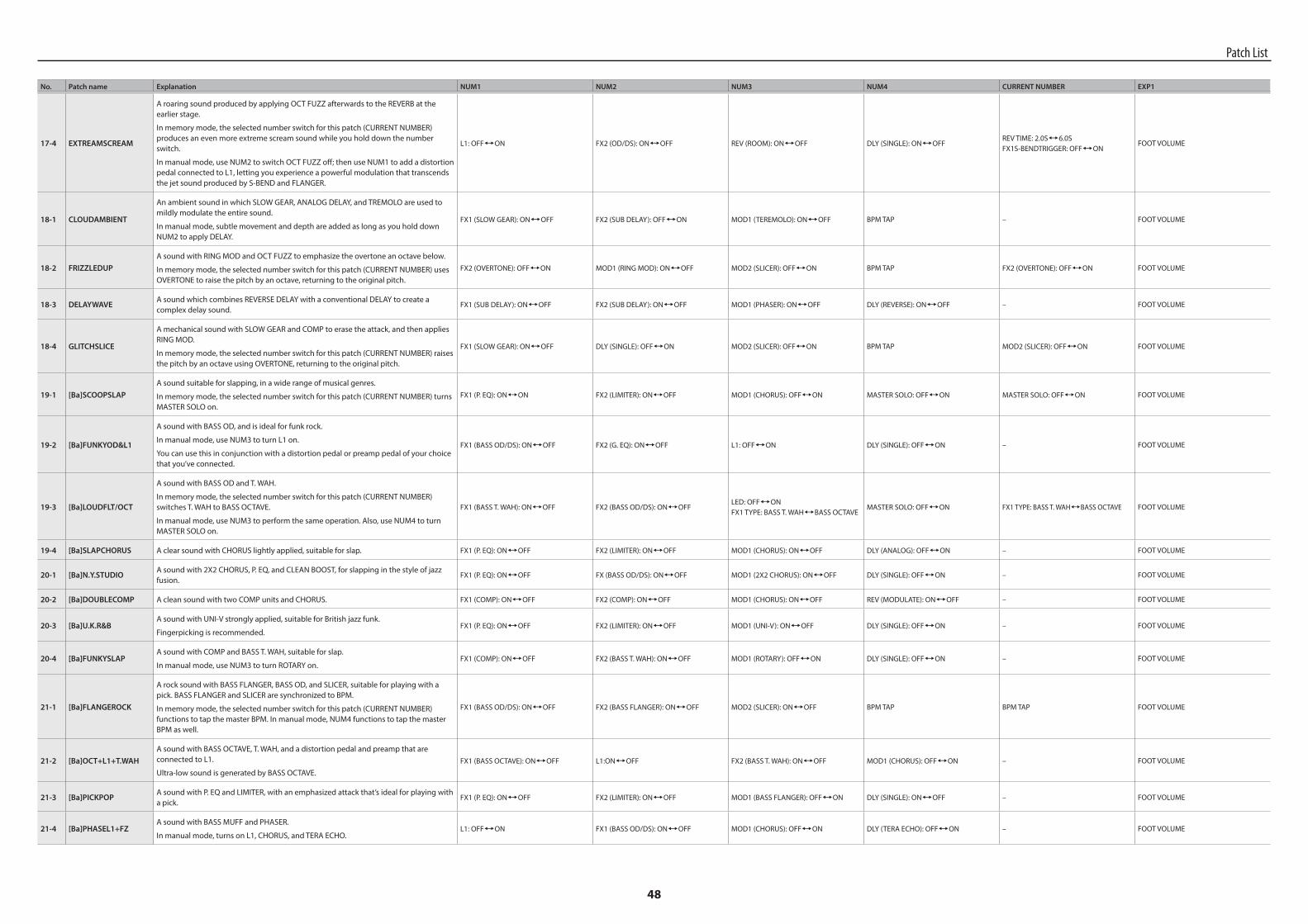
48
No. Patch name Explanation NUM1 NUM2 NUM3 NUM4 CURRENT NUMBER EXP1
17-4 EXTREAMSCREAM
A roaring sound produced by applying OCT FUZZ afterwards to the REVERB at the earlier stage.
In memory mode, the selected number switch for this patch (CURRENT NUMBER) produces an even more extreme scream sound while you hold down the number switch.
In manual mode, use NUM2 to switch OCT FUZZ off; then use NUM1 to add a distortion pedal connected to L1, letting you experience a powerful modulation that transcends the jet sound produced by S-BEND and FLANGER.
L1: OFF,ON FX2 (OD/DS): ON,OFF REV (ROOM): ON,OFF DLY (SINGLE): ON,OFFREV TIME: 2.0S,6.0SFX1S-BENDTRIGGER: OFF,ON
FOOT VOLUME
18-1 CLOUDAMBIENT
An ambient sound in which SLOW GEAR, ANALOG DELAY, and TREMOLO are used to mildly modulate the entire sound.
In manual mode, subtle movement and depth are added as long as you hold down NUM2 to apply DELAY.
FX1 (SLOW GEAR): ON,OFF FX2 (SUB DELAY): OFF,ON MOD1 (TEREMOLO): ON,OFF BPM TAP – FOOT VOLUME
18-2 FRIZZLEDUPA sound with RING MOD and OCT FUZZ to emphasize the overtone an octave below.
In memory mode, the selected number switch for this patch (CURRENT NUMBER) uses OVERTONE to raise the pitch by an octave, returning to the original pitch.
FX2 (OVERTONE): OFF,ON MOD1 (RING MOD): ON,OFF MOD2 (SLICER): OFF,ON BPM TAP FX2 (OVERTONE): OFF,ON FOOT VOLUME
18-3 DELAYWAVEA sound which combines REVERSE DELAY with a conventional DELAY to create a complex delay sound.
FX1 (SUB DELAY): ON,OFF FX2 (SUB DELAY): ON,OFF MOD1 (PHASER): ON,OFF DLY (REVERSE): ON,OFF – FOOT VOLUME
18-4 GLITCHSLICE
A mechanical sound with SLOW GEAR and COMP to erase the attack, and then applies RING MOD.
In memory mode, the selected number switch for this patch (CURRENT NUMBER) raises the pitch by an octave using OVERTONE, returning to the original pitch.
FX1 (SLOW GEAR): ON,OFF DLY (SINGLE): OFF,ON MOD2 (SLICER): OFF,ON BPM TAP MOD2 (SLICER): OFF,ON FOOT VOLUME
19-1 [Ba]SCOOPSLAPA sound suitable for slapping, in a wide range of musical genres.
In memory mode, the selected number switch for this patch (CURRENT NUMBER) turns MASTER SOLO on.
FX1 (P. EQ): ON,ON FX2 (LIMITER): ON,OFF MOD1 (CHORUS): OFF,ON MASTER SOLO: OFF,ON MASTER SOLO: OFF,ON FOOT VOLUME
19-2 [Ba]FUNKYOD&L1
A sound with BASS OD, and is ideal for funk rock.
In manual mode, use NUM3 to turn L1 on.
You can use this in conjunction with a distortion pedal or preamp pedal of your choice that you’ve connected.
FX1 (BASS OD/DS): ON,OFF FX2 (G. EQ): ON,OFF L1: OFF,ON DLY (SINGLE): OFF,ON – FOOT VOLUME
19-3 [Ba]LOUDFLT/OCT
A sound with BASS OD and T. WAH.
In memory mode, the selected number switch for this patch (CURRENT NUMBER) switches T. WAH to BASS OCTAVE.
In manual mode, use NUM3 to perform the same operation. Also, use NUM4 to turn MASTER SOLO on.
FX1 (BASS T. WAH): ON,OFF FX2 (BASS OD/DS): ON,OFFLED: OFF,ONFX1 TYPE: BASS T. WAH,BASS OCTAVE
MASTER SOLO: OFF,ON FX1 TYPE: BASS T. WAH,BASS OCTAVE FOOT VOLUME
19-4 [Ba]SLAPCHORUS A clear sound with CHORUS lightly applied, suitable for slap. FX1 (P. EQ): ON,OFF FX2 (LIMITER): ON,OFF MOD1 (CHORUS): ON,OFF DLY (ANALOG): OFF,ON – FOOT VOLUME
20-1 [Ba]N.Y.STUDIOA sound with 2X2 CHORUS, P. EQ, and CLEAN BOOST, for slapping in the style of jazz fusion.
FX1 (P. EQ): ON,OFF FX (BASS OD/DS): ON,OFF MOD1 (2X2 CHORUS): ON,OFF DLY (SINGLE): OFF,ON – FOOT VOLUME
20-2 [Ba]DOUBLECOMP A clean sound with two COMP units and CHORUS. FX1 (COMP): ON,OFF FX2 (COMP): ON,OFF MOD1 (CHORUS): ON,OFF REV (MODULATE): ON,OFF – FOOT VOLUME
20-3 [Ba]U.K.R&BA sound with UNI-V strongly applied, suitable for British jazz funk.
Fingerpicking is recommended.FX1 (P. EQ): ON,OFF FX2 (LIMITER): ON,OFF MOD1 (UNI-V): ON,OFF DLY (SINGLE): OFF,ON – FOOT VOLUME
20-4 [Ba]FUNKYSLAPA sound with COMP and BASS T. WAH, suitable for slap.
In manual mode, use NUM3 to turn ROTARY on. FX1 (COMP): ON,OFF FX2 (BASS T. WAH): ON,OFF MOD1 (ROTARY): OFF,ON DLY (SINGLE): OFF,ON – FOOT VOLUME
21-1 [Ba]FLANGEROCK
A rock sound with BASS FLANGER, BASS OD, and SLICER, suitable for playing with a pick. BASS FLANGER and SLICER are synchronized to BPM.
In memory mode, the selected number switch for this patch (CURRENT NUMBER) functions to tap the master BPM. In manual mode, NUM4 functions to tap the master BPM as well.
FX1 (BASS OD/DS): ON,OFF FX2 (BASS FLANGER): ON,OFF MOD2 (SLICER): ON,OFF BPM TAP BPM TAP FOOT VOLUME
21-2 [Ba]OCT+L1+T.WAHA sound with BASS OCTAVE, T. WAH, and a distortion pedal and preamp that are connected to L1.
Ultra-low sound is generated by BASS OCTAVE.FX1 (BASS OCTAVE): ON,OFF L1:ON,OFF FX2 (BASS T. WAH): ON,OFF MOD1 (CHORUS): OFF,ON – FOOT VOLUME
21-3 [Ba]PICKPOPA sound with P. EQ and LIMITER, with an emphasized attack that’s ideal for playing with a pick.
FX1 (P. EQ): ON,OFF FX2 (LIMITER): ON,OFF MOD1 (BASS FLANGER): OFF,ON DLY (SINGLE): ON,OFF – FOOT VOLUME
21-4 [Ba]PHASEL1+FZA sound with BASS MUFF and PHASER.
In manual mode, turns on L1, CHORUS, and TERA ECHO.L1: OFF,ON FX1 (BASS OD/DS): ON,OFF MOD1 (CHORUS): OFF,ON DLY (TERA ECHO): OFF,ON – FOOT VOLUME
Patch List
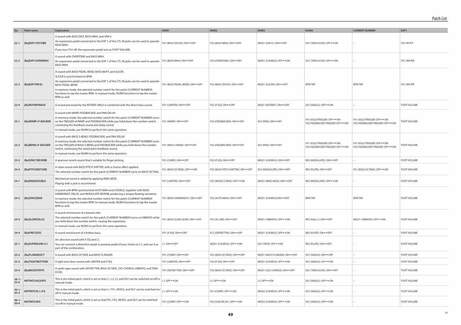
49
No. Patch name Explanation NUM1 NUM2 NUM3 NUM4 CURRENT NUMBER EXP1
22-1 [Ba]EXP1CRYVIBE
A sound with BASS DIST, BASS WAH, and UNI-V.
An expression pedal connected to the EXP 1 of the CTL IN jacks can be used to operate BASS WAH.
If you turn FX2 off, the expression pedal acts as FOOT VOLUME.
FX1 (BASS OD/DS): ON,OFF FX2 (BASS WAH): ON,OFF MOD1 (UNI-V): ON,OFF DLY (TERA ECHO): OFF,ON – FX2: W/P/F
22-2 [Ba]EXP1OVERWAHA sound with OVERTONE and BASS WAH.
An expression pedal connected to the EXP 1 of the CTL IN jacks can be used to operate BASS WAH.
FX1 (BASS WAH): ON,OFF FX2 (OVERTONE): ON,OFF MOD1 (CHORUS): OFF,ON DLY (TERA ECHO): OFF,ON – FX1: WH/PB
22-3 [Ba]EXP1PB/SL
A sound with BASS PEDAL BEND, BASS MUFF, and SLICER.
SLICER is synchronized to BPM.
An expression pedal connected to the EXP 1 of the CTL IN jacks can be used to operate BASS PEDAL BEND.
In memory mode, the selected number switch for this patch (CURRENT NUMBER) functions to tap the master BPM. In manual mode, NUM4 functions to tap the master BPM as well.
FX1 (BASS PEDAL BEND): ON,OFF FX2 (BASS OD/DS): ON,OFF MOD1 (SLICER): ON,OFF BPM TAP BPM TAP FX1: WH/PB
22-4 [Ba]ROTARYBASS A sound processed by the ROTARY effect is combined with the direct bass sound. FX1 (LIMITER): ON,OFF FX2 (P. EQ): ON,OFF MOD1 (ROTARY): ON,OFF DLY (SINGLE): OFF,ON – FOOT VOLUME
23-1 [Ba]WARP+F-BACKER
A sound with WARP, FEEDBACKER, and PAN DELAY.
In memory mode, the selected number switch for this patch (CURRENT NUMBER) turns on the TRIGGER of WARP and FEEDBACKER while you hold down the number switch, continuing the feedback sound and delay sound.
In manual mode, use NUM4 to perform the same operation.
FX1 (WARP): ON,OFF FX2 (FEEDBACKER): ON,OFF DLY (PAN): ON,OFFFX1 SOLO/TRIGGER: OFF,ONFX2 FEEDBACKER TRIGGER: OFF,ON
FX1 SOLO/TRIGGER: OFF,ONFX2 FEEDBACKER TRIGGER: OFF,ON
FOOT VOLUME
23-2 [Ba]BEND+F-BACKER
A sound with BASS S-BEND, FEEDBACKER, and PAN DELAY.
In memory mode, the selected number switch for this patch (CURRENT NUMBER) turns on the TRIGGER of BASS S-BEND and FEEDBACKER while you hold down the number switch, continuing the raised-pitch feedback sound.
In manual mode, use NUM4 to perform the same operation.
FX1 (BASS S-BEND): ON,OFF FX2 (FEEDBACKER): ON,OFF DLY (PAN): ON,OFFFX1 SOLO/TRIGGER: OFF,ONFX2 FEEDBACKER TRIGGER: OFF,ON
FX1 SOLO/TRIGGER: OFF,ONFX2 FEEDBACKER TRIGGER: OFF,ON
FOOT VOLUME
23-3 [Ba]SPACYREVERB A spacious reverb sound that’s suitable for finger picking. FX1 (COMP): ON,OFF FX2 (P. EQ): ON,OFF MOD1 (CHORUS): ON,OFF REV (MODULATE): ON,OFF – FOOT VOLUME
23-4 [Ba]PITCHDETUNEA clean sound with BASS PITCH SHIFTER, with a chorus effect applied.
The selected number switch for this patch (CURRENT NUMBER) turns on BASS OCTAVE.FX1 (BASS OCTAVE): OFF,ON FX2 (BASS PITCH SHIFTER): ON,OFF DLY (MODULATE): ON,OFF REV (PLATE): ON,OFF FX1 (BASS OCTAVE): OFF,ON FOOT VOLUME
24-1 [Ba]RINGDOUBLEMechanical sound is added by applying RING MOD.
Playing with a pick is recommend.FX1 (LIMITER): ON,OFF FX2 (BASSO CTAVE): OFF,ON MOD1 (RING MOD): ON,OFF REV (MODULATE): OFF,ON – FOOT VOLUME
24-2 [Ba]SPACEBAR
A sound with BPM-synchronized AUTO WAH and CHORUS, together with BASS HARMONIST, DELAY, and MODULATE REVERB, producing a unique floating sensation.
In memory mode, the selected number switch for this patch (CURRENT NUMBER) functions to tap the master BPM. In manual mode, NUM4 functions to tap the master BPM as well.
FX1 (BASS HARMONIST): ON,OFF FX2 (AUTO WAH): ON,OFF MOD1 (CHORUS):ON,OFF BPM TAP BPM TAP FOOT VOLUME
24-3 [Ba]SLOWCELLO
A sound reminiscent of a bowed cello.
The selected number switch for this patch (CURRENT NUMBER) turns on VIBRATO while you hold down the number switch, varying the expression.
In manual mode, use NUM3 to perform the same operation.
FX1 (BASS SLOW GEAR): ON,OFF FX2 (AC.SIM): ON,OFF MOD1 (VIBRATO): OFF,ON REV (HALL1): ON,OFF MOD1 (VIBRATO): OFF,ON FOOT VOLUME
24-4 [Ba]FRETLESS A sound reminiscent of a fretless bass. FX1 (P. EQ): ON,OFF FC2 (DEFRETTER): ON,OFF MOD1 (CHORUS): OFF,ON REV (PLATE): ON,OFF – FOOT VOLUME
25-1 [Ba]SUPERLOW+L1An ultra-low sound with P. EQ and L1.
You can connect a distortion pedal or preamp pedal of your choice to L1, and use it as part of the combination.
L1: ON,OFF MOD1 (CHORUS): OFF,ON DLY (TAPE): OFF,ON REV (PLATE): ON,OFF – FOOT VOLUME
25-2 [Ba]FLANGEOCT A sound with BASS OCTAVE and BASS FLANGER. FX1 (COMP): ON,OFF FX2 (BASS OCTAVE): ON,OFF MOD1 (BASS FLANGER): ON,OFF DLY (SINGLE): ON,OFF – FOOT VOLUME
25-3 [Ba]TIGHTBOTTOM A tight and clean sound with LIMITER and P. EQ. FX1 (LIMITER): ON,OFF FX2 (P. EQ): ON,OFF MOD1 (CHORUS): OFF,ON DLY (SINGLE): OFF,ON – FOOT VOLUME
25-4 [Ba]BASSSYNTHA synth-type sound with DEFRETTER, BASS OCTAVE, 2X2 CHORUS, VIBRATO, and TERA ECHO.
FX1 (DEFRETTER): ON,OFF FX2 (BASS OCTAVE): ON,OFF MOD1 (2X2 CHORUS): ON,OFF DLY (TERA ECHO): ON,OFF – FOOT VOLUME
26-1–35-4 INITPATCHLOOPS
This is the initial patch, which is set so that L1, L2, L3, and DLY can be switched on/off in manual mode.
L1: OFF,ON L2: OFF,ON L3: OFF,ON DLY (SINGLE): OFF,ON – FOOT VOLUME
36-1–45-4 INITPATCHL1+FX
This is the initial patch, which is set so that L1, FX1, MOD2, and DLY can be switched on/off in manual mode.
L1: OFF,ON FX1 (COMP): OFF,ON MOD2 (CHORUS): OFF,ON DLY (SINGLE): OFF,ON – FOOT VOLUME
46-1–50-4 INITPATCHFX
This is the initial patch, which is set so that FX1, FX2, MOD2, and DLY can be switched on/off in manual mode.
FX1 (COMP): OFF,ON FX2 (SUB DELAY): OFF,ON MOD2 (CHORUS): OFF,ON DLY (SINGLE): OFF,ON – FOOT VOLUME
Patch List
01