Embed Size (px)
Citation preview
PARALLEL TESSELLATION USING COMPUTE SHADERS
Team Members: David Sierra Erwin Holzhauser Matt Faller
Project Sponsors: Mangesh Nijasure
Todd MartinSaad Arrabi
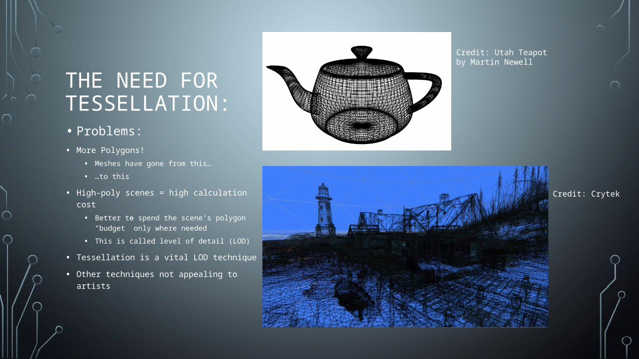
THE NEED FOR TESSELLATION:• Problems:• More Polygons!
• Meshes have gone from this…
• …to this
• High-poly scenes = high calculation cost
• Better to spend the scene’s polygon “budget” only where needed
• This is called level of detail (LOD)
• Tessellation is a vital LOD technique
• Other techniques not appealing to artists
Credit: Utah Teapot by Martin Newell
Credit: Crytek
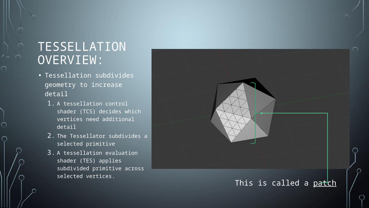
TESSELLATION OVERVIEW:• Tessellation subdivides
geometry to increase detail1. A tessellation control shader
(TCS) decides which vertices need additional detail
2. The Tessellator subdivides a selected primitive
3. A tessellation evaluation shader (TES) applies subdivided primitive across selected vertices.
This is called a patch
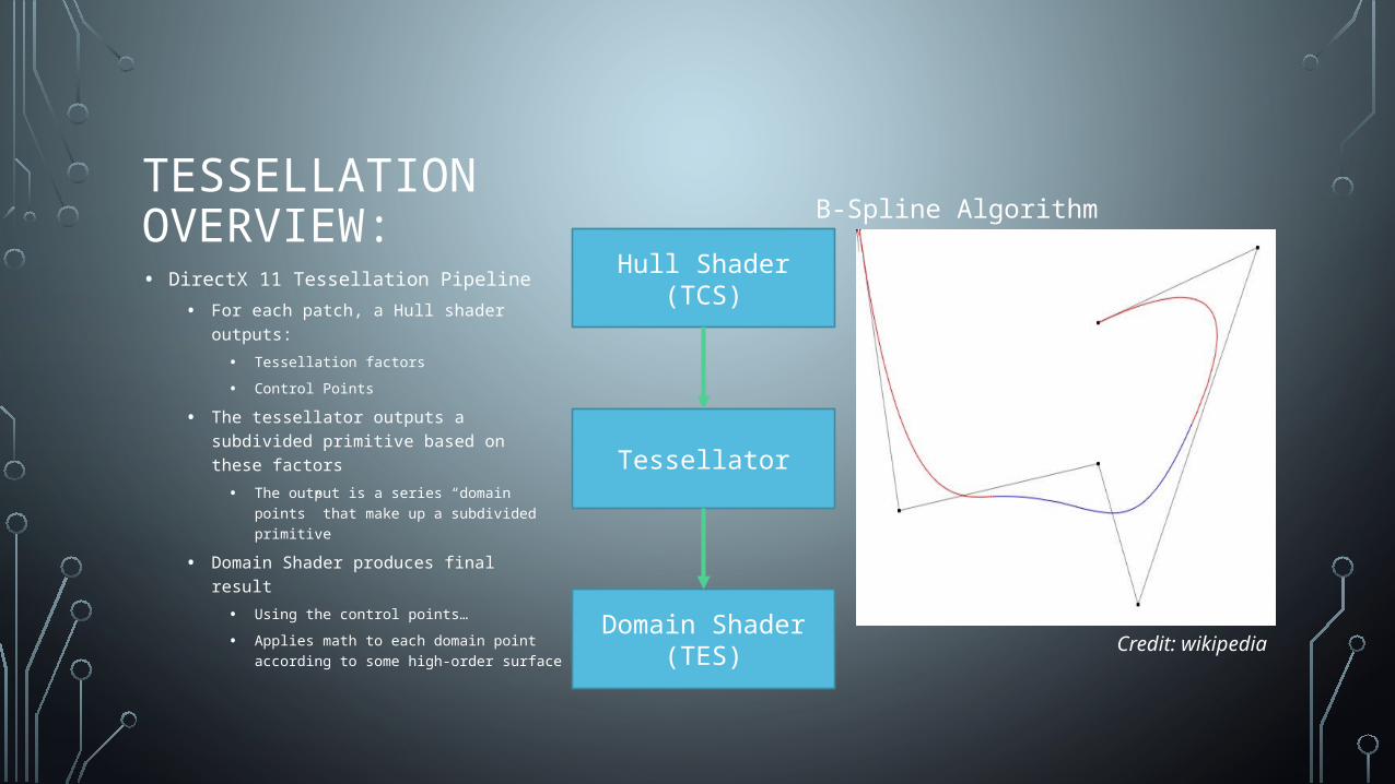
TESSELLATION OVERVIEW:• DirectX 11 Tessellation Pipeline
• For each patch, a Hull shader outputs:
• Tessellation factors
• Control Points
• The tessellator outputs a subdivided primitive based on these factors
• The output is a series “domain points” that make up a subdivided primitive
• Domain Shader produces final result
• Using the control points…
• Applies math to each domain point according to some high-order surface Domain Shader (TES)
Tessellator
Hull Shader (TCS)
B-Spline Algorithm
Credit: wikipedia
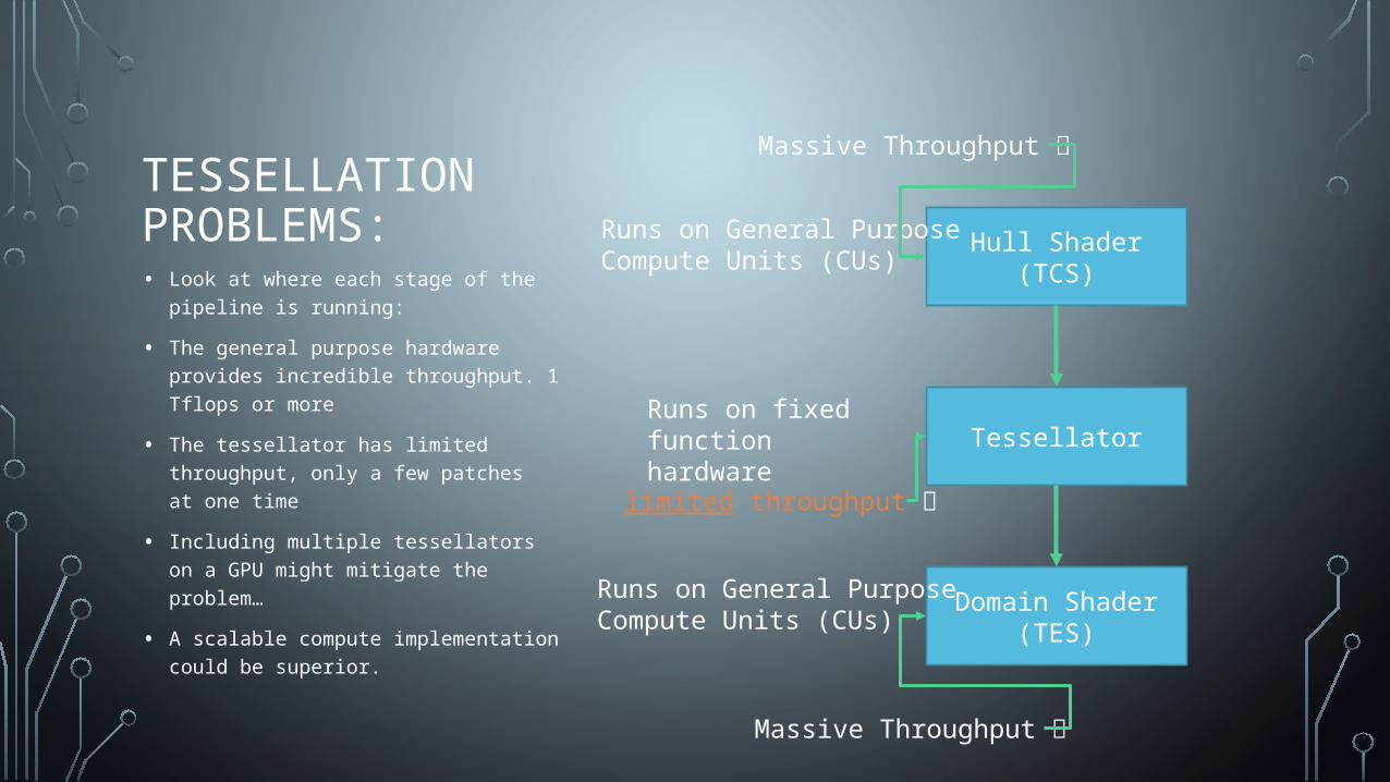
TESSELLATION PROBLEMS:• Look at where each stage of the pipeline
is running:
• The general purpose hardware provides incredible throughput. 1 Tflops or more
• The tessellator has limited throughput, only a few patches at one time
• Including multiple tessellators on a GPU might mitigate the problem…
• A scalable compute implementation could be superior.
Domain Shader (TES)
Tessellator
Hull Shader (TCS)Runs on General PurposeCompute Units (CUs)
Runs on General PurposeCompute Units (CUs)
Runs on fixed functionhardware
Massive Throughput
Massive Throughput
limited throughput
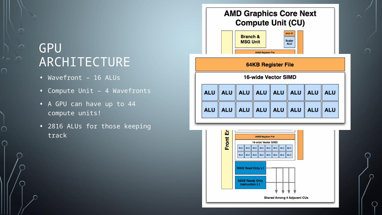
GPU ARCHITECTURE• Wavefront – 16 ALUs
• Compute Unit – 4 Wavefronts
• A GPU can have up to 44 compute units!
• 2816 ALUs for those keeping track
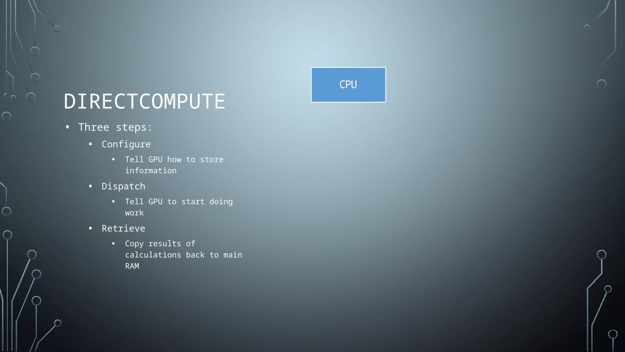
DIRECTCOMPUTE• Three steps:
• Configure
• Tell GPU how to store information
• Dispatch
• Tell GPU to start doing work
• Retrieve
• Copy results of calculations back to main RAM
CPUCPU GPU
Configure Buffers
Dispatch
Copy Results
Data
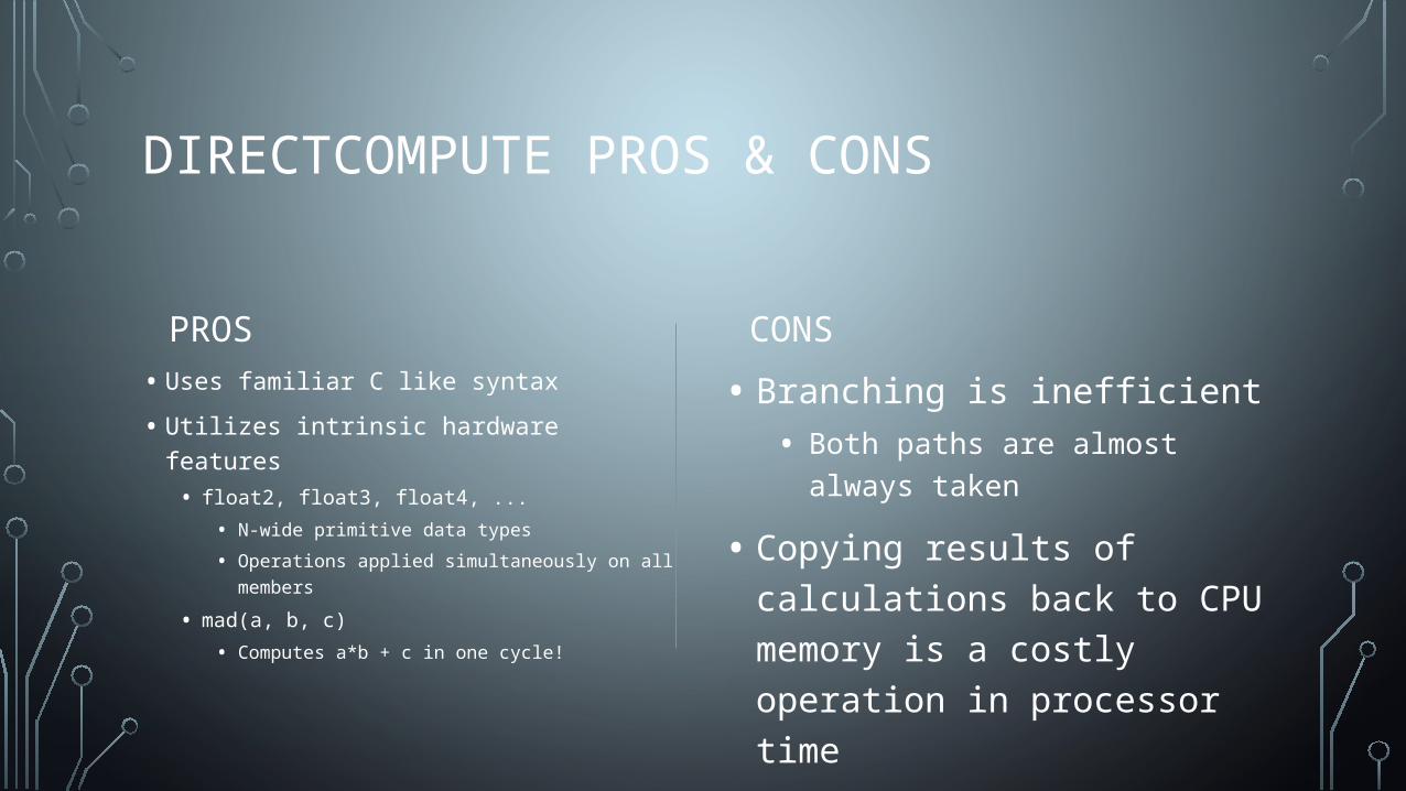
DIRECTCOMPUTE PROS & CONS
PROS
• Uses familiar C like syntax
• Utilizes intrinsic hardware features• float2, float3, float4, ...
• N-wide primitive data types
• Operations applied simultaneously on all members
• mad(a, b, c)
• Computes a*b + c in one cycle!
CONS
• Branching is inefficient• Both paths are almost always taken
• Copying results of calculations back to CPU memory is a costly operation in processor time
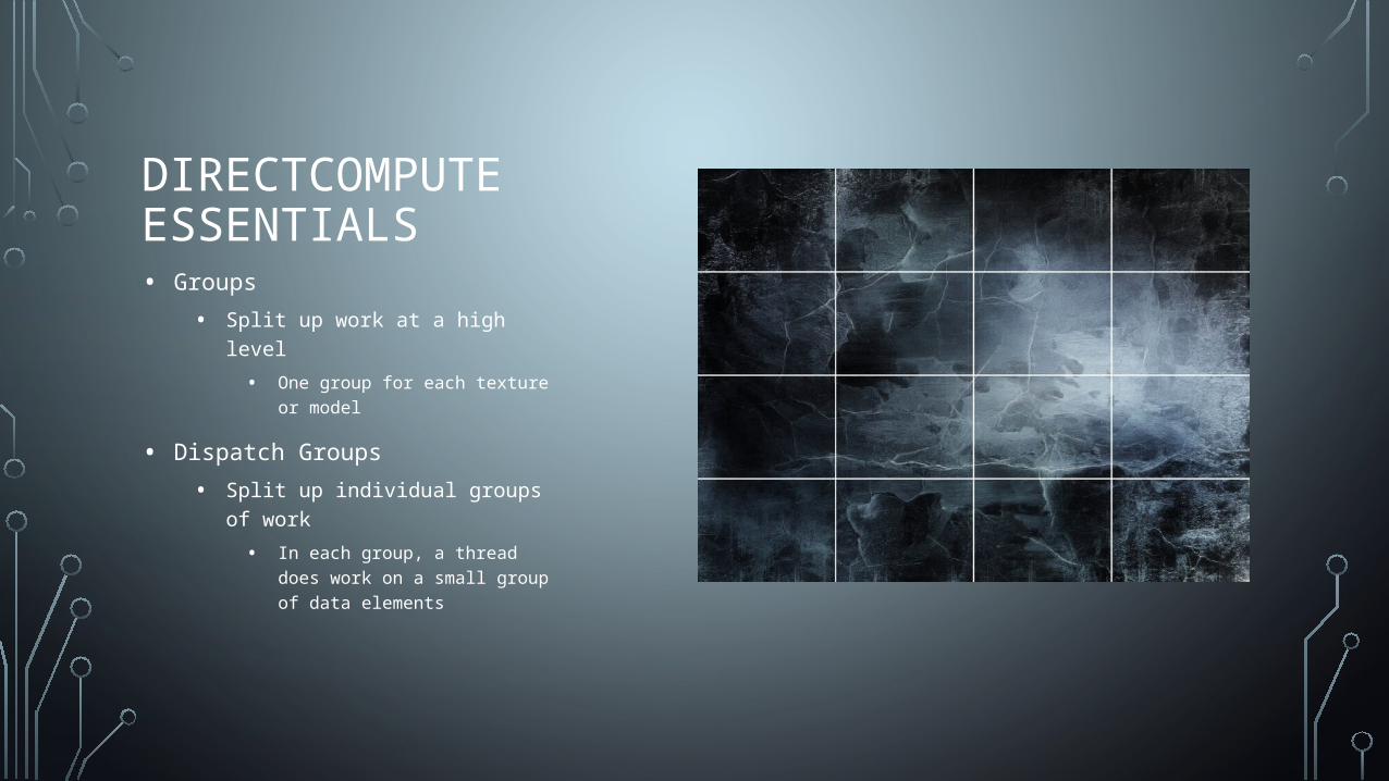
DIRECTCOMPUTE ESSENTIALS• Groups
• Split up work at a high level
• One group for each texture or model
• Dispatch Groups
• Split up individual groups of work
• In each group, a thread does work on a small group of data elements
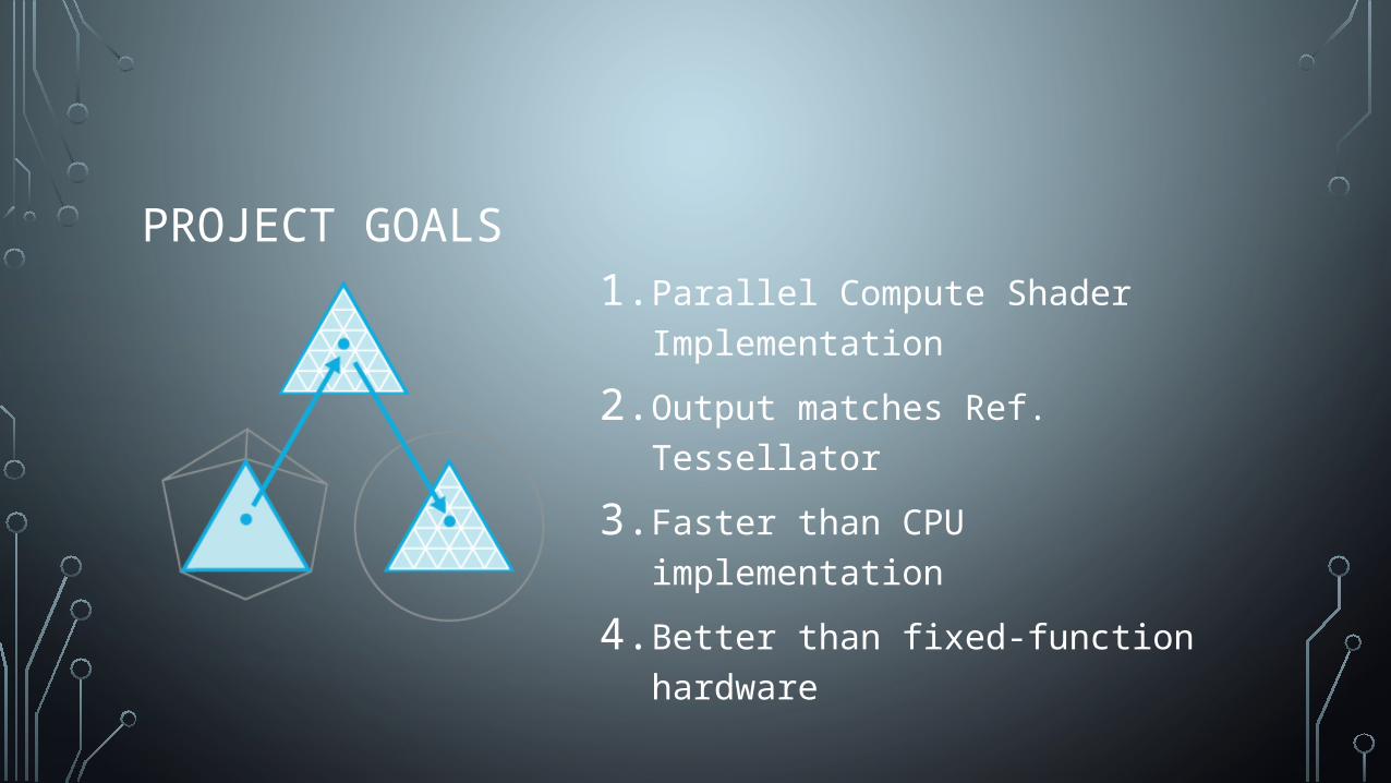
PROJECT GOALS1. Parallel Compute Shader Implementation
2. Output matches Ref. Tessellator
3. Faster than CPU implementation
4. Better than fixed-function hardware
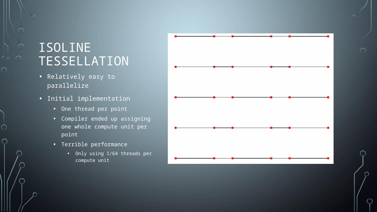
ISOLINE TESSELLATION• Relatively easy to parallelize
• Initial implementation
• One thread per point
• Compiler ended up assigning one whole compute unit per point
• Terrible performance
• Only using 1/64 threads per compute unit
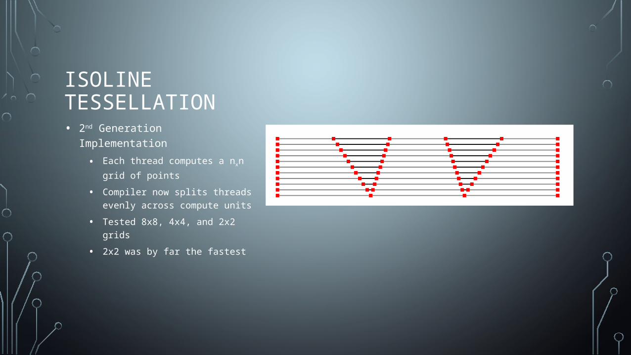
ISOLINE TESSELLATION• 2nd Generation Implementation
• Each thread computes a nxn grid of
points
• Compiler now splits threads evenly across compute units
• Tested 8x8, 4x4, and 2x2 grids
• 2x2 was by far the fastest

ISOLINE TESSELLATION• 3rd Generation Implementation
• Each thread computes 1 point
• Launch these threads 64 at a time to minimize resources used.
• Very fast
• Threads are launched 8x8 or 64x1

TRI TESSELLATION
• 4 Tess. Factors• Partitioning Mode
PointGeneration
Shader
Vertex Buffer Index Buffer
1st Outer = 2
2nd Outer = 5
3rd Outer = 1
Inner = 4PointConnectivity
Shader
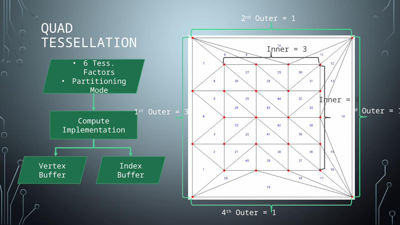
QUAD TESSELLATION
• 6 Tess. Factors• Partitioning Mode
Compute Implementation
Vertex Buffer Index Buffer
1st Outer = 3
2nd Outer = 1
3rd Outer = 1
4th Outer = 1
Inner = 3
Inner = 4
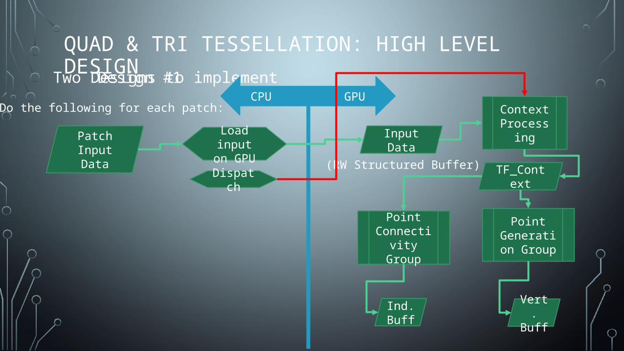
QUAD & TRI TESSELLATION: HIGH LEVEL DESIGNTwo Designs to implementDesign #1
Context Processing
Point Generation
Group
Point Connectivity
Group
Do the following for each patch:
Patch Input Data
Load input on GPU
CPUGPU
Input Data
(RW Structured Buffer)Dispatch TF_Context
Vert. Buff
Ind. Buff
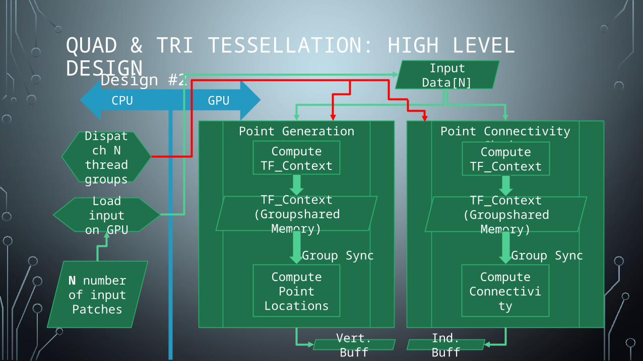
QUAD & TRI TESSELLATION: HIGH LEVEL DESIGNDesign #2
Point Generation Shader
N number of input Patches
Load input on GPU
CPUGPU
Input Data[N]
Dispatch N thread groups
TF_Context (Groupshared Memory)
Vert. Buff Ind. Buff
Point Connectivity Shader
Compute TF_Context
TF_Context (Groupshared Memory)
Compute TF_Context
ComputePoint Locations
ComputeConnectivity
Group Sync Group Sync
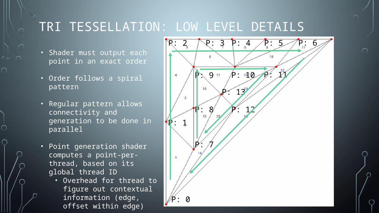
TRI TESSELLATION: LOW LEVEL DETAILS
P: 0
P: 1
P: 2 P: 3 P: 4 P: 5 P: 6
P: 7
P: 8
P: 9 P: 10 P: 11
P: 12
P: 13
• Shader must output each point in an exact order
• Order follows a spiral pattern
• Regular pattern allows connectivity and generation to be done in parallel
• Point generation shader computes a point-per-thread, based on its global thread ID• Overhead for thread to figure out
contextual information (edge, offset within edge)
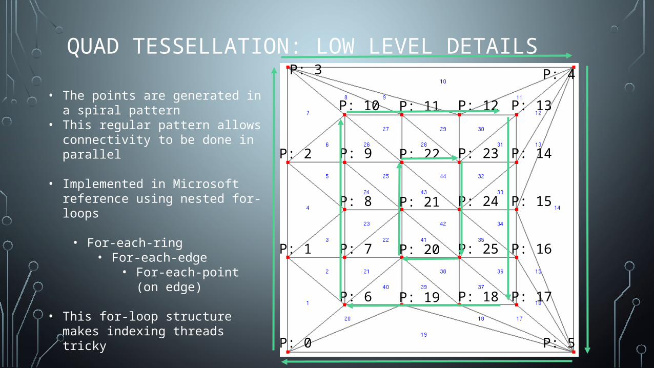
QUAD TESSELLATION: LOW LEVEL DETAILS
P: 0
P: 1
P: 2
P: 3 P: 4
P: 5
P: 6
P: 7
P: 8
P: 9
P: 10
P: 19
P: 20
P: 21
P: 22
P: 11
P: 18
P: 25
P: 24
P: 23
P: 12
P: 17
P: 16
P: 15
P: 14
P: 13• The points are generated in a spiral
pattern• This regular pattern allows connectivity
to be done in parallel
• Implemented in Microsoft reference using nested for-loops
• For-each-ring• For-each-edge
• For-each-point (on edge)
• This for-loop structure makes indexing threads tricky
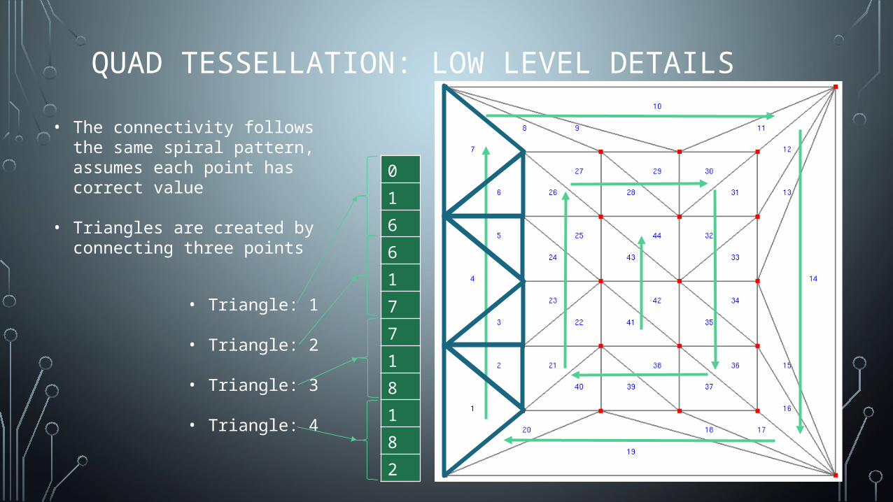
QUAD TESSELLATION: LOW LEVEL DETAILS
• The connectivity follows the same spiral pattern, assumes each point has correct value
• Triangles are created by connecting three points
0
1
6
6
1
7
7
1
8
1
8
2
• Triangle: 1
• Triangle: 2
• Triangle: 3
• Triangle: 4
QUAD & TRI TESSELLATION: LOW LEVEL DETAILS
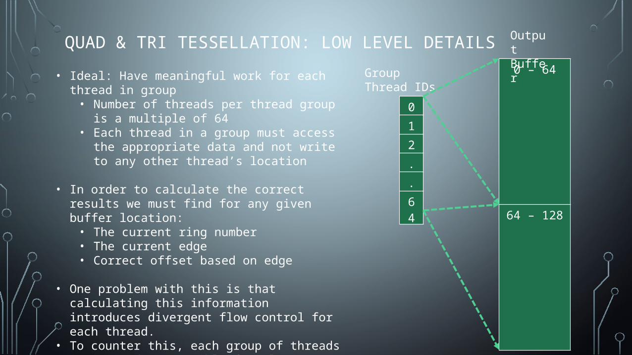
• Ideal: Have meaningful work for each thread in group• Number of threads per thread group is a multiple of
64• Each thread in a group must access the appropriate
data and not write to any other thread’s location
• In order to calculate the correct results we must find for any given buffer location:• The current ring number• The current edge• Correct offset based on edge
• One problem with this is that calculating this information introduces divergent flow control for each thread.
• To counter this, each group of threads is instead responsible for placing points and connections on each edge. (although this sacrifices cache performance)
Group Thread IDs
0
1
2
.
.
64
0 – 64
64 – 128
OutputBuffer
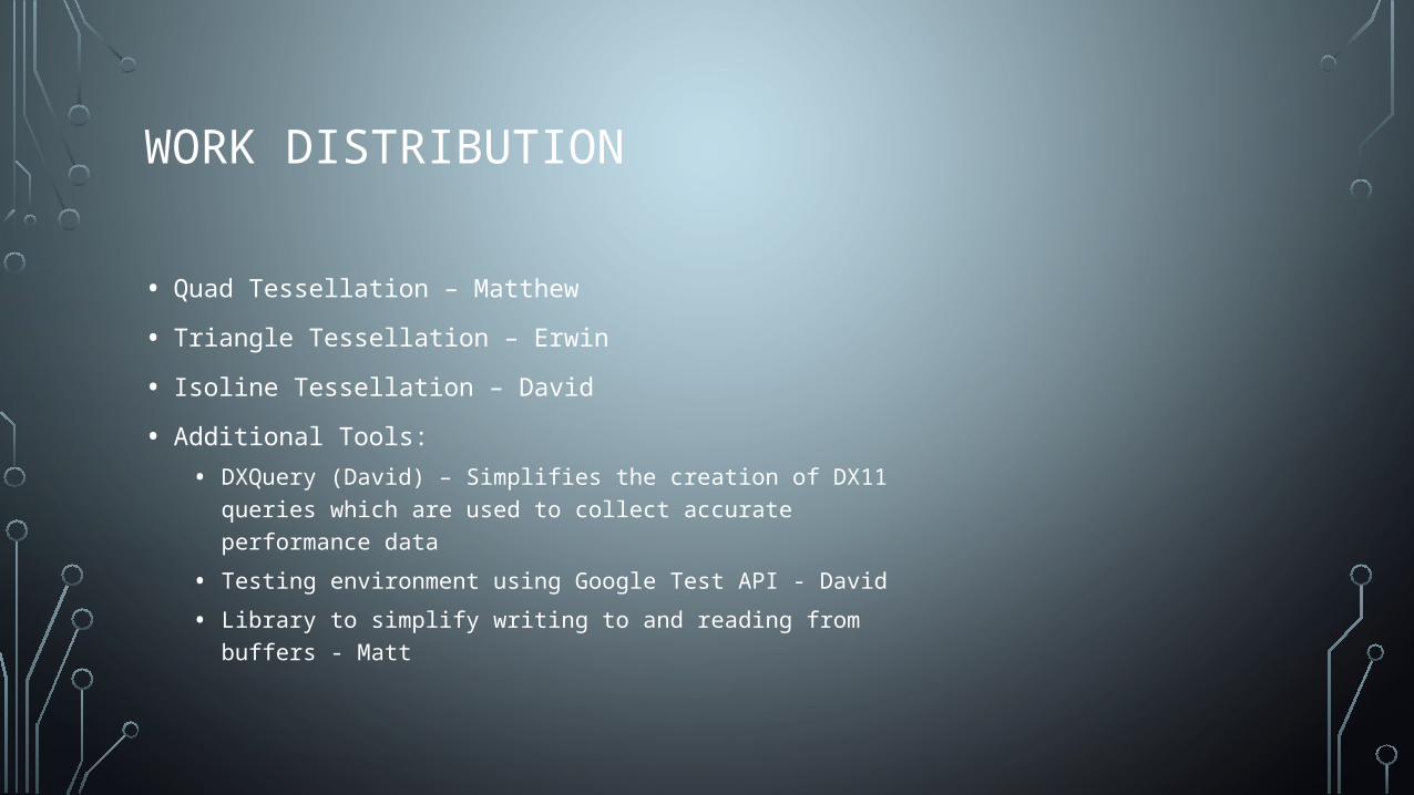
WORK DISTRIBUTION
• Quad Tessellation – Matthew
• Triangle Tessellation – Erwin
• Isoline Tessellation – David
• Additional Tools:
• DXQuery (David) – Simplifies the creation of DX11 queries which are used to collect accurate performance data
• Testing environment using Google Test API - David
• Library to simplify writing to and reading from buffers - Matt

BUDGET
• Radeon R9 290X Graphics Card – The cheapest runs from $360 on Newegg, bought with AMD donation
• Practical Rendering and Computation with Direct3D 11 – Runs from ~$50 on Amazon
• Bitbucket – Free for teams under 5 users
• Private code repository
• Visual Studio Professional - Free through UCF’s DreamSpark membership
Credit: Newegg.com
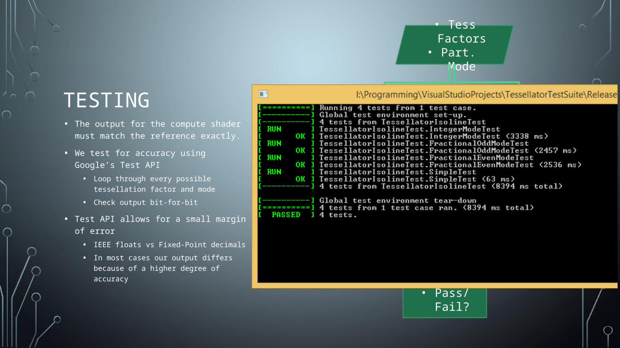
TESTING• The output for the compute shader must
match the reference exactly.
• We test for accuracy using Google’s Test API
• Loop through every possible tessellation factor and mode
• Check output bit-for-bit
• Test API allows for a small margin of error
• IEEE floats vs Fixed-Point decimals
• In most cases our output differs because of a higher degree of accuracy
Reference Implementation
Shader Implementation
• Tess Factors• Part. Mode
Google Test• Pass/Fail?
• Vertex Buff• Index Buff
• Vertex Buff• Index Buff
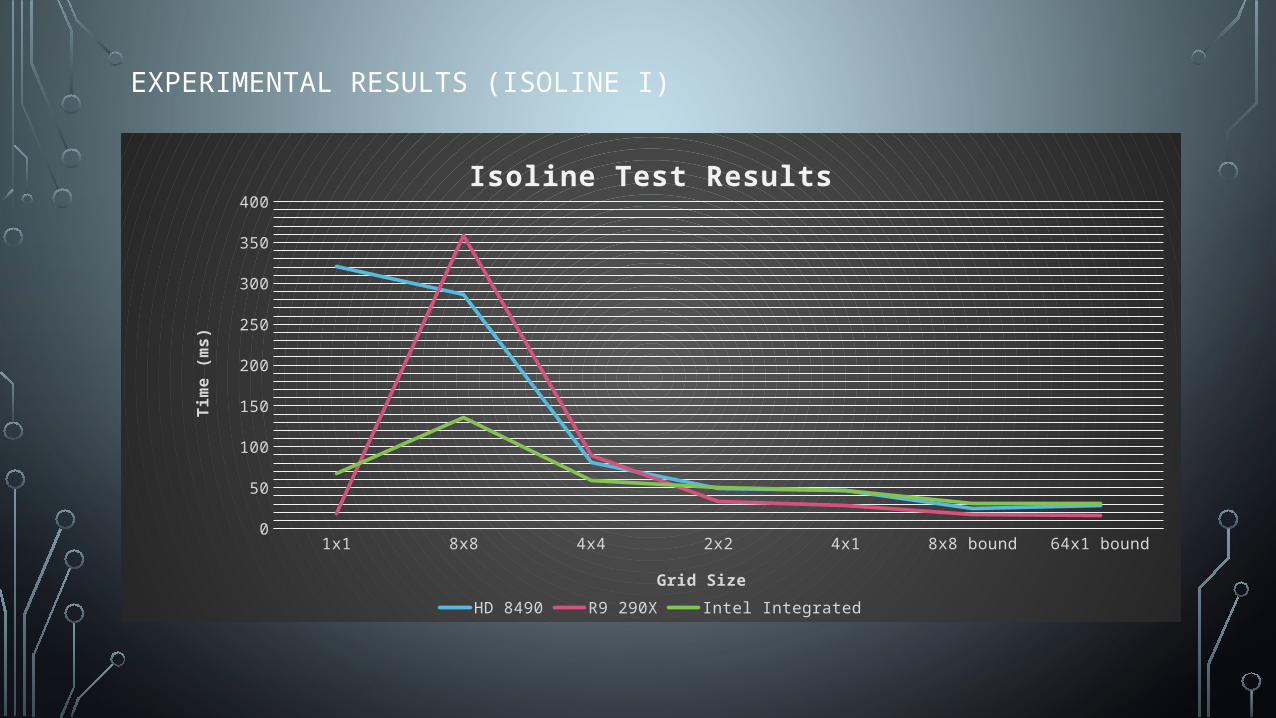
EXPERIMENTAL RESULTS (ISOLINE I)
1x1 8x8 4x4 2x2 4x1 8x8 bound 64x1 bound0
50
100
150
200
250
300
350
400
Isoline Test Results
HD 8490 R9 290X Intel Integrated
Grid Size
Tim
e (m
s)
EXPERIMENTAL RESULTS (ISOLINE II)
16x16 32x16 64x15 32x32 48x48 64x640
0.005
0.01
0.015
0.02
0.025
Isoline Test Results
CPU GPU
Grid Size
Tim
e (m
s)
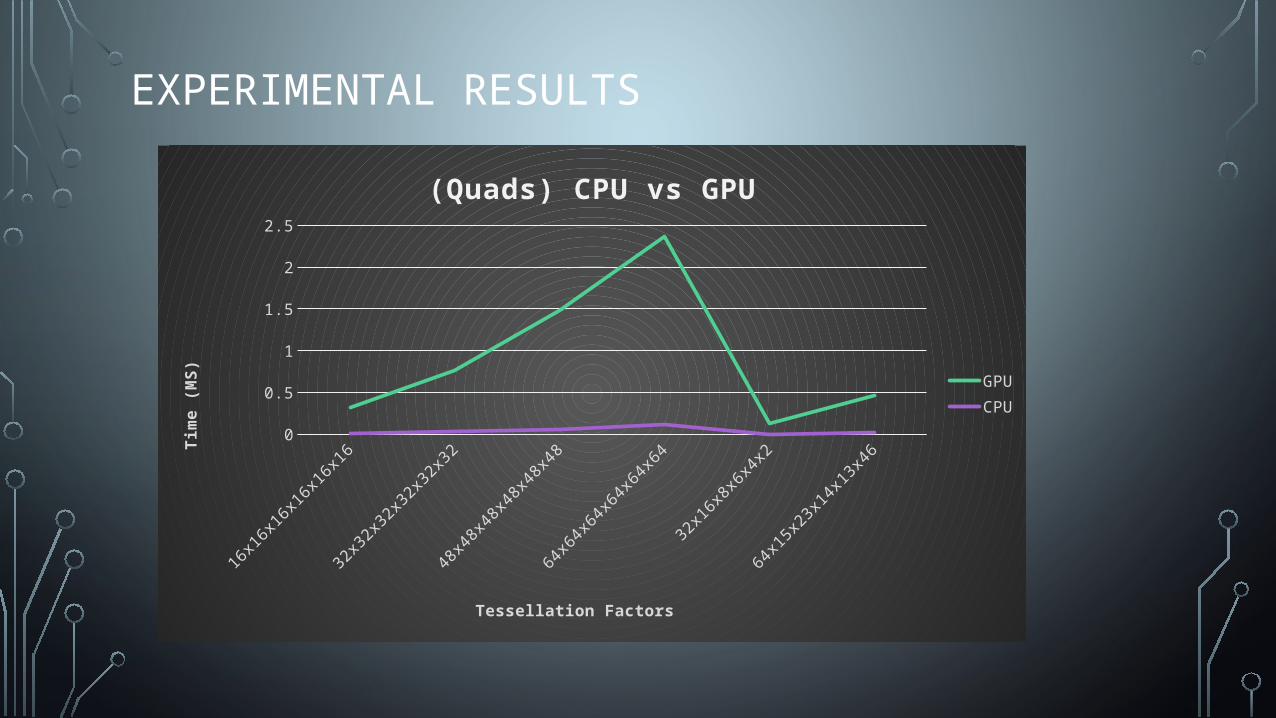
EXPERIMENTAL RESULTS
16x16x1
6x16x1
6x16
32x32x3
2x32x3
2x32
48x48x4
8x48x4
8x48
64x64x6
4x64x6
4x64
32x16x8
x6x4
x2
64x15x2
3x14x1
3x46
0
0.5
1
1.5
2
2.5
(Quads) CPU vs GPU
GPUCPU
Tessellation Factors
Tim
e (M
S)
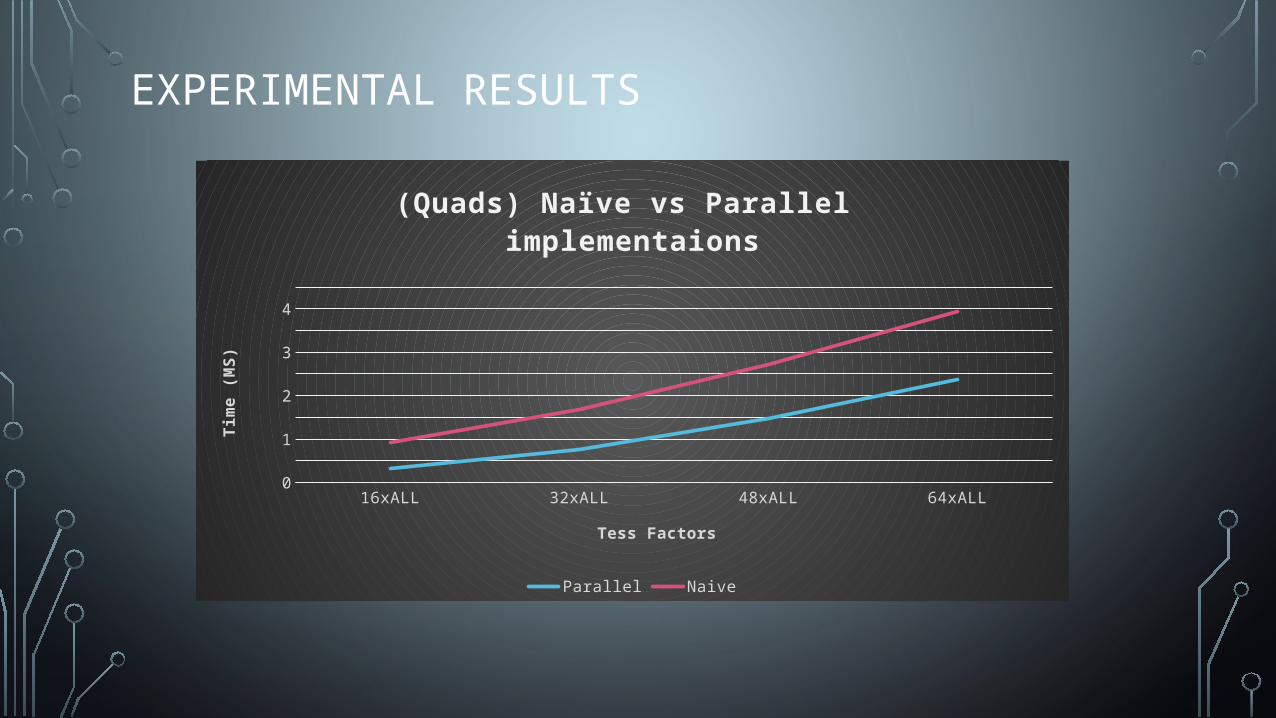
EXPERIMENTAL RESULTS
16xALL 32xALL 48xALL 64xALL0
0.5
1
1.5
2
2.5
3
3.5
4
4.5
(Quads) Naïve vs Parallel implementaions
Parallel Naive
Tess Factors
Tim
e (M
S)
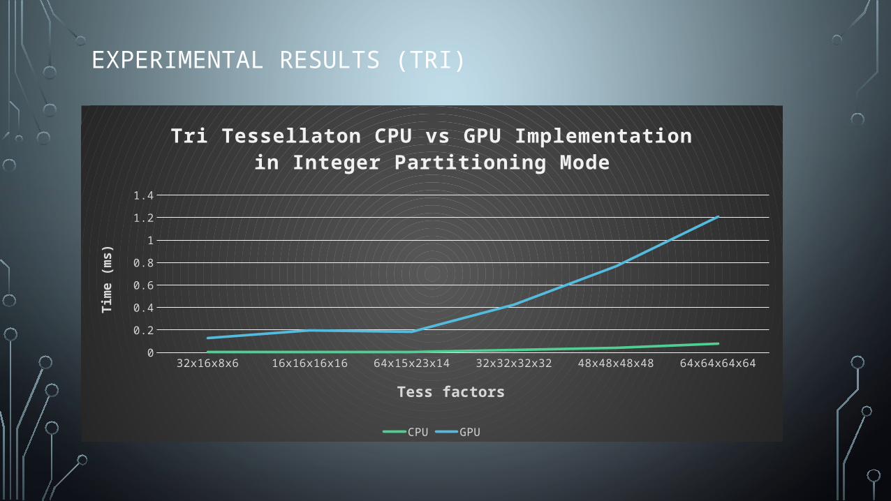
EXPERIMENTAL RESULTS (TRI)
32x16x8x6 16x16x16x16 64x15x23x14 32x32x32x32 48x48x48x48 64x64x64x640
0.2
0.4
0.6
0.8
1
1.2
1.4
Tri Tessellaton CPU vs GPU Implementation in Integer Par -titioning Mode
CPU GPU
Tess factors
Tim
e (m
s)

QUESTIONS?