Embed Size (px)
Citation preview

PARALLEL SEISMIC IMAGING IN OIL EXPLORATION
Imagenología Sísmica Paralela en Exploración Petrolera
JOSÉ COLMENARES, JORGE RODRÍGUEZ y GERMÁN LARRAZÁVALCentro Multidisciplinario de Visualización y Cómputo Científico (CeMViCC)
Universidad de Carabobo. Facultad Experimental de Ciencia y Tecnología.Carabobo. Venezuela.
{fjcolmenares5, jrodrigu, glarraza}@uc.edu.ve
Fecha de Recepción: 07/05/2009, Fecha de Revisión: 01/03/2010, Fecha de Aceptación: 15/07/2010
Abstract
In this work, we present an efficient parallel implementation of a depth migration RTM (Reverse Time Migration) method to obtain a seismic image. This migration technique is based on the parallel solution of the acoustic wave propagation in 2D using a finite difference scheme. We have implemented a domain decomposition on the geological section and exploit an efficient asynchronous communication between processors using MPI library. We test our implementation on a theoretical model from Tupure-Carora reservoir, Venezuela. We have applied HPC technique on a Sun Grid Cluster belongs to CEMVICC. This cluster has 16 dual AMD opteron processors, having a total of 32 processors. We have obtained a cuasi–linear speed–up.
Keywords: Acoustic wave propagation, Depth migration, Domain decomposition.
Resumen
En este trabajo, se presenta una implementación eficiente paralela de un algoritmo de migración en profundidad llamado RTM (Reverse Time Migration) para obtener una imagen sísmica. Esta técnica de migración está basada en la solución paralela de la propagación de la onda acústica en 2D usando un esquema de diferencias finitas. Se implementó una descomposición de dominio sobre la sección geológicay se exploto una eficiente comunicación asíncrona estre los procesadores usando la libraría MPI. La implementación fue probada usando un modelo teórico del yacimiento Tupure-Carora, Venezuela. Se aplicaron técnicas de HPC sobre un Cluster de computadores Sun Grid pertenecientes al CEMVICC. Este cluster tiene 16 nodos duales AMD opteron, teniendo un total de 32 procesadores. Se ha obtenido una aceleración cuasi-lineal.
Palabra Claves: Descomposición en dominios, Migración en profundidad, Propagación de onda acústica.
ISSN 1698 - 7418Depósito Legal PP200402CA1617FARAUTE Ciens. y Tec., 5(1): 40-46, 2010 José Colmenares, Jorge Rodríguez y Germán Larrazával
FARAUTE Ciens. y Tec., 5(1). 2010
1. Introduction memory is important in any implementation of seismic migration technique. In Oldfield et al.,
Seismic modeling is an important part of (1998) is presented an approach in handling the seismic processing, because it provides the massive I/O requirements of seismic processing seismic answer given a terrain model. The and they shows the performance of their image algorithms used for seismic wave modeling to code on Intel Paragom computer. They solved the compute the seismic answer for a given terrain 3D wave equation to use a depth migration model, require large CPU times and memory prestack technique. In Ho Kim et al. (2005) is (Phadke et al., 1998). Methods based on the wave introduced a parallel algorithm which can equation (Phadke et al., 1998) have been gaining calculate the traveltime and amplitude for popularity in recent years, because they provide Kirchhoff migration that is one of seismic more detailed and fine geological features than imaging technique. In this work, we have tested other conventional techniques, and also preserve our parallel RTM algorithm from Tupure–Carora the amplitude of the information. The most reservoir, Venezuela. The obtained result shows commonly employed numerical techniques are the good perfomance of the algorithm.seismic migration and forward modeling. Migration is the last and more intensive step in the 2. Reverse Time Migrationlong chain of processing seismic data. Migration can be executed in time-domain as well as in The RTM is based on the full acoustic wave depth-domain. If there are strong lateral equation. It is based solely on the symmetry of the variations of the velocity, time migration acoustic wave equation in time, which makes it followed by time to depth conversion does not possible to use basically the same finite–difference represent the reflected energy in its true code for extrapolating the recorded wavefields subsurface position. Depth-migration is essential backward in time as in forward modeling. The in these cases, because it compensates for the ray RTM can treat arbitrarily complex velocity bending, lateral velocity pullups and structure. A variations and is particularly well suited for dealing natural advantage of depth-migration is that the with abrupt velocity changes at saltsediment output image is shown as a function of depth, and interfaces. The steps to RTM algorithm are:thus it can be used directly in geological interpretation. All these types of migration can be 1. A model of the subsurface is constructed that applied in 2D and 3D datasets. For obvious mimics the true spatial variation of the seismic reasons, the resolution is far better in 3D velocity in the survey area in x, y and z. Such migration, at the expense of a larger models are normally constructed based on computational cost. In this work, we have initial interpretations of the seismic data, developed a parallel algorithm based on reverse velocity analysis, and well data, if available.time migration (RTM) to obtain a seismic image. The RTM has been described by many authors 2. The one-way travel times from surface (Baysal et al., 1983; Loewenthal & Mufti, 1983; source locations to a grid of subsurface McMechan, 1983; Whitmore, 1983), and since points is determined by forward wave then it has been implemented in many cases propagation using the exploding re?ectors (Chang & McMechan, 1994). These works model, and while doing so saving the wave stablished RTM as a very general imaging tool for front at the source locations. In this work, seismic reflection data. The RTM is accurate, but this is done using a finite difference method.expensive. Therefore, to reduce the CPU time and
40 41

Parallel Seismic Imaging in Oil Exploration
FARAUTE Ciens. y Tec., 5(1). 2010
3. The migrated depth section is constructed by where Äx = Äz is the distance between the sampling the reversely propagating wave field horizontal and vertical nodes, respectively, and at the extraction time at each subsur-face point. the Eq. (5) is satisfied.The extraction time associated with a depth point corresponds to the time at which a re?ection refocuses at the true reflector position. In the reversely propagating wave field the recorded wave front at the source locations is Solving for the next time step (k + 1), and used as boundary condition at the surface. using the average to approximate the value of the
density for the nodal points, the final finite 2.1. Forward wave propagation model differences approximation isexpressed in Eq. (6).
The RTM model implemented in this work is based on (Bordin, 1995; Bordin & Lines, 1999).We consider the acoustic wave equation in heterogeneous media. This equation is obtained from Euler’s relation and continuity equation
The criterion of stability is given by the Eq. (7).
where P is the acoustic pressure, p is the density, and c is where c is the maximum velocity in the media and the wave velocity on the medium and the src(t) is the √2 results from the model dimension, 2D in this source function at the time t. We use a finite difference case. According to Alford et al. (1974). the method to discretize the Eq. (1). The second derivative following relation will be used in order to minimize with respect to time can be approximated using the dispersion in the model the relationship of the centered differences :Eq. (8) will be used.
where the term ë represents the dominant dominantwhere Ät is the time step. The spacial derivatives wavelength in the model. We need to de?ne also can be approximated by an equation in absorbing and nonre?ecting boundary conditions differences, as is shown for the component x and the in order to avoid undesirable re?ection. We use component z (Eq. (3) and Eq. (4) respectively.attenuation conditions on the left, right, bottom and top (Reynolds, 1978). Applying some algebraic manipulations, these boundary conditions are expressed by Eq. (9), (10), (11) and (12)
left boundary
expressed as Eq. (1).
as Eq. (2) shows
(2)
(3)
(4)
(6)
(7)
(8)
(9)
(5)
(1)
FARAUTE Ciens. y Tec., 5(1). 2010
José Colmenares, Jorge Rodríguez y Germán Larrazával
Fig. 2. MPI communication
Fig. 1. Problem domain, partition in z-direction
right boundary
top boundary
process of propagation of the wave is carried out, and then a message is sent with the values of
bottom boundary pressure of the last row that was evaluated the following node; it receives a message from the following node with the values of pressure of the first row that evaluated this node.
.c(i,j) t?where cb(i, j) = . Also, we use the function ? x
of weights presented by Cerjan et al., (1985) as nonre?ecting boundary conditions. The pressure amplitudes outside the boundary lines must be multiplied by G factor (see Eq. (13)).
2-[0,015(20-i) ]G = exp
A source function is required to generate the seismic wave. The method used in this work will beto simulate a dynamite explosion to generate the seismic waves. In our case, a ricker wavelet If it is an intermediate node, the process of was used. wave propagation is also executed, but two
messages are sent, the first one with the values of 2.2. Parallel Algorithm pressure on the first row to the previous node and
the second message with the data of pressure of the The parallel implementation of the last row to the following node; at the same time two
algorithm is based on domain decomposition messages are received, first from the previous node using MPI library. Domain decomposition in that corresponds to the values of pressure of its last volves assigning sub-domains of the computational row and the second message is received from the domain to different processors and solving the following node with the data of pressure of its first equations for each sub-domain concurrently. row. If it is the last node, it happens exactly the same Here, the domain is partitioned in z–direction with the propagation process, the difference is that (Fig. 1). this one send a message to the previous node with
the values of pressure of its first row, and receives a We use an asynchronous comunication to message from that previous node with the data of
obtain a good performance. If it is the node zero case, pressure of its last row. All this process can be memory is assigned for the seismogram data, the visualized in the Fig. 2.
(10)
(11)
(12)
(13)
42 43

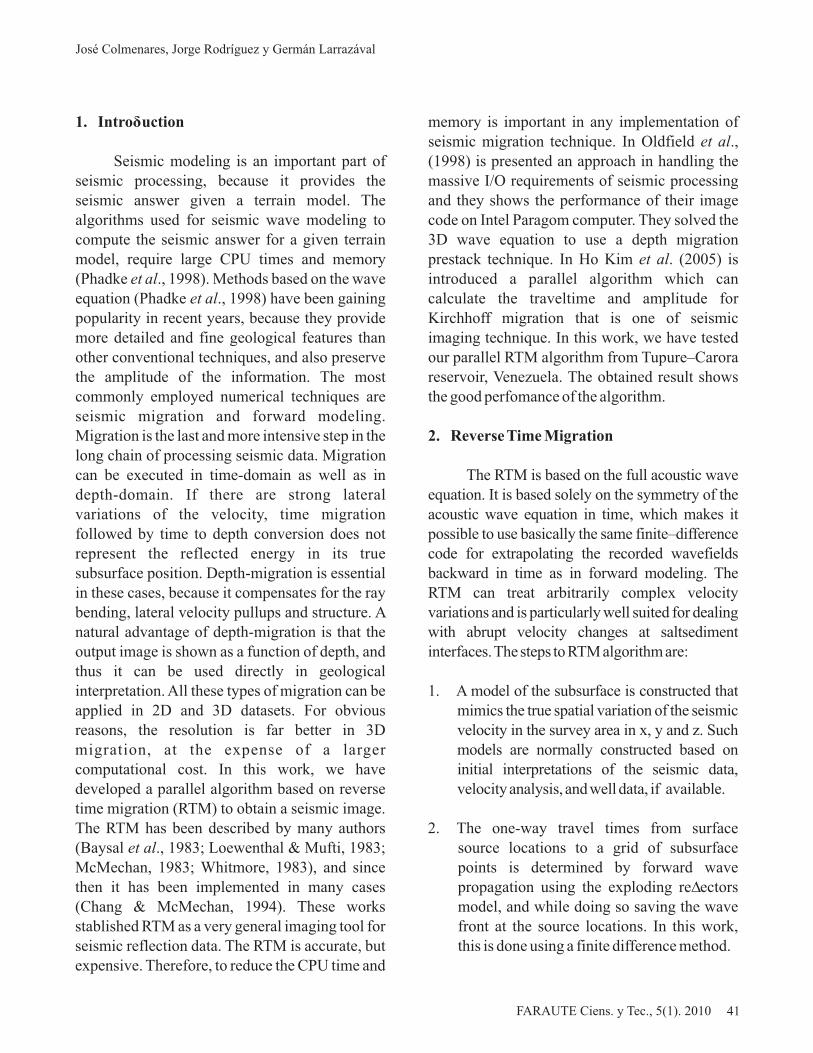
Fig. 3. Tupure–Carora reservoir, Venezuela: 2D uniformvelocity model.
Fig. 6. Synthetic seismogram.
Fig. 7. 2D seismic image from RTM.
a) CPU time.
Fig. 5. P wave propagation.
b) Speed–up.
Fig. 4. RTM performance.
3. Test Problem and Performance
The hardware platform is a Sun Grid Cluster machine with 16 Opteron 248 dual nodes, having a total of 32 processors. The parallel RTM code was developed in ANSI C applying HPC techniques, specially optimization flags and blocking (minimization of cache misses). The parameters file of the code has the following values: simulation time (in seconds), time step (in seconds), frecuency (in Hz.) and sample of seismic record.We have used our parallel RTMalgorithm to tune the seismic acquisition parameters of a theoretical-geological section of Tupure–Carora reservoir. The section has 119,200 meters in–line and 22,400 meters in depht. We have used 2,384 gathers/shots on the section. The simulation time was 5 seconds and we used 60 Hz of maximal frequency, using a Ricker wavelet.
We can observe a 2D uniform velocity model from Tupure–Carora reservoir in the Fig. 3. The maximal velocity is 5,100 m/s and the minimal velocity is 2,500m/s. Themodel has constant density.
A 2D seismic image is generated running the parallel code. In Fig. 4 we can observe the CPU time and speed-up obtained. We can see a cuasi–linear speed–up until 32 processors.
Fig. 5 shows the snapshot for the P wave propagation at 5 seconds, the shot was at 60,000 meters and the Fig. 6 presents the synthetic seismogram, respectively. Fig. 7 shows the seismic image from RTM
Parallel Seismic Imaging in Oil Exploration
FARAUTE Ciens. y Tec., 5(1). 2010 FARAUTE Ciens. y Tec., 5(1). 2010
Fig. 8. 2D seismic image from sumiggbzo.
implementation. We can observe some structures 6. Bibliographypresented in the Fig. 3, and the Fig. 8 shows the image obtained by PDVSA using sumiggbzo Alford R., K. Kelly & D. Boore. (1974). Accuracy routine (migration via Gaussian Beams of Zero- of finite–difference modeling of the acoustic wave Offset data) from the Seismic Un*x package equation. Geophysics. 39(6): 834-842.developed at Colorado School of Mines.
Baysal E., D. Kosloff & J. Sherwood. (1983). Reverse time migration. Geophysics. 48(11): 1514-1524.
Bordin R. (1995). Seismic wave propagation modeling and inversion. Computational Sciences Educational Project. Stanford University. USA.
Comparing the Fig. 7 and 8 with initial uniform velocity model is clear that the RTM Bordin R. & L. Lines. (1999). Seismic modeling methodology offers best resolution. and imaging with the complete wave equation.
Society of Exploration Geophysicists (SEG) 4. Conclusions Publication. Tulsa. Oklahoma.
In this work, we have presented an efficient Cerjan C., D. Kosloff, R. Kosloff & M. Reshef. parallel implementation of a depth migration RTM (1985). A nonreflecting boundary condition for (Reverse Time Migration) method to obtain a discrete acosutic and elastic wave equations. seismic image. We have implemented a domain Geophysics. 50(8): 705-708.decomposition on the geological section and exploit an efficient asynchronous communication Chang W. & G. McMechan. (1994). 3D elastic between processors using MPI library. We have prestack reverse time depth migration. Geophysics. tested our implementation for a theoretical model 59(4): 597-609. from Tupure-Carora reservoir, Venezuela. We have applied HPC techniques on a Sun Grid Cluster Ho Kim J., D. Yang & C. Shin. (2005). 3D seismic belongs to CEMVICC, obtaining a cuasi–linear imaging using high–performance parallel direct speed–up until 32 processors. solver for large–scale finite element analysis.
Proceedings of Eighth Int. Conference on 5. Acknowledgements High–Performance Computing in Asia–Pacific
Region (HPCASIA’05). IEEE Computer Society. We want to thank to Victor Pereyra and Pedro Beijing. China. 187-194.
Linares by their right suggestions in the development of this work. Also, we want to thank to Loewenthal D. & I. Mufti. (1983). Reverse time Rafael Borges and Maikel Vera by their migration in spatial frequency domain. colaboration in this project. A special thank to Geophysics. 48: 627-635.PDVSA Company to permit to use the data from Tupure–Carora reservoir. Also, this work is McMechan G. (1983). Migration by extrapolation sponsored by CDCH–UC under No. 2005-010 and of time–dependent boundary values. Geophys. Sun Microsystems Inc. under Center of Excellence Prosp. 31(2): 413-420.project: HPC and Grid for Oil Exploration.
José Colmenares, Jorge Rodríguez y Germán Larrazával
44 45

Oldfield R., D. Womble & D. Ober. (1998). Efficient parallel I/O in seismic imaging, Int. J. High Perform. Comput. Appl. 12(3): 333-344.
Phadke, S., D. Bhardwaj & S. Yerneni. (1998). Wave equation based migration and modellingalgorithms on parallel computers. Proceedings of SPG´98. Chennai. India. 55-59.
Reynolds A. (1978). Boundary conditions for the numerical solution of wave propagation problems. Geophysics. 43(6): 1099-1110.
Whitmore N. (1983). Iterative depth migration by backward time propagation. 53rd Ann. Internat. Mtg. Soc. Expl. Geophys. Expanded Abstract.Las Vegas. USA. 382-385.
Parallel Seismic Imaging in Oil Exploration
FARAUTE Ciens. y Tec., 5(1). 2010
ADAPTACIÓN DEL DRIVER DE LA TARJETA DE RED D-LINK DGE-530T PARA GAMMA
D-Link DGE-530T Network Interface Card Driver Adaptation for GAMMA
KIARA A. OTTOGALLI F., DANIEL H. ROSQUETE DE M., AMADÍS A. MARTÍNEZ M. y FREDDY J. PEROZO R.
Departamento de ComputaciónFacultad Experimental de Ciencias y Tecnología. Universidad de Carabobo
Valencia, Estado Carabobo, Venezuela{kottogal, dhrosquete, aamartin, fperozo}@uc.edu.ve
Fecha de Recepción: 08/07/2009, Fecha de Revisión: 16/06/2010, Fecha de Aceptación: 30/07/2010
Resumen
Un cluster es un sistema de computo formado por varios computadores con hardware similar, que se comunican a través de una red de alta velocidad, que funciona como un único computador. Se puede construir un cluster de PCs, pero la velocidad de comunicación entre sus nodos es notablemente menor en comparación a la de un cluster especializado de alto costo, debido al uso de controladores (drivers) no especializados para tarjetas (Gigabit) en cluster que utilizan la pila de protocolos TCP/IP. En este artículo se describe la adaptación de un controlador para la NIC (Network Interface Card) D-Link DGE-530T compatible con GAMMA (Genoa Active Message MAchine) y los resultados que comprueban que dicho controlador mejora el rendimiento del cluster de bajo costo del Departamento de Computación de la FaCyT-UC, denominado Mangosta.
Palabras clave: Cluster, Driver, GAMMA, Optimización de comunicaciones, Tarjetas de red.
Abstract
A cluster is a computer system formed by several computers with similar hardware, which maintains the communication among them through a high-speed network, working together as a single integrated resource. It is possible to built a cluster of PCs, but the communication speed among its nodes is considerably slower compared with the communication speed of a high-cost specialized one due to the use of non-specialized (Gigabit) network card drivers that uses the TCP/IP protocol stack for communication purposes. In this article are described the adaptation of a D-Link DGE-530T NIC (Network Interface Card) driver compatible with GAMMA (Genoa Active Message MAchine) and the tests that con?rm that the driver improves the performance of the low-cost cluster of the Department of Computer Science of the FaCyT-UC, known as Mangosta.
Keywords: Cluster, Communication optimization, Driver, GAMMA, Network card.
ISSN 1698 - 7418Depósito Legal PP200402CA1617FARAUTE Ciens. y Tec., 5(1): 47-58, 2010
46 47