Embed Size (px)
Citation preview

CONCURRENCY: PRACTICE AND EXPERIENCE, VOL. 9(10), 947–965 (OCTOBER 1997)
Parallel implementation of a ray tracing algorithmfor distributed memory parallel computersTONG-YEE LEE1, C. S. RAGHAVENDRA2 AND JOHN B. NICHOLAS3
1Department of Information Management, Nantai Institute of Technology, Tainan County, Taiwan, Republic ofChina
2School of Electrical Engineering and Computer Science, Washington State University, Pullman, WA 99164, USA
3Environmental Molecular Science Laboratory, Pacific Northwest Laboratory Richland, WA 99352, USA
SUMMARYRay tracing is a well known technique to generate life-like images. Unfortunately, ray trac-ing complex scenes can require large amounts of CPU time and memory storage. Distributedmemory parallel computers with large memory capacities and high processing speeds are idealcandidates to perform ray tracing. However, the computational cost of rendering pixels andpatterns of data access cannot be predicted until runtime. To parallelize such an application effi-ciently on distributed memory parallel computers, the issues of database distribution, dynamicdata management and dynamic load balancing must be addressed. In this paper, we presenta parallel implementation of a ray tracing algorithm on the Intel Delta parallel computer. Inour database distribution, a small fraction of database is duplicated on each processor, whilethe remaining part is evenly distributed among groups of processors. In the system, there aremultiple copies of the entire database in the memory of groups of processors. Dynamic datamanagement is acheived by an ALRU cache scheme which can exploit image coherence to re-duce data movements in ray tracing consecutive pixels. We balance load among processors bydistributing subimages to processors in a global fashion based on previous workload requests.The success of our implementation depends crucially on a number of parameters which areexperimentally evaluated. 1997 by John Wiley & Sons, Ltd.
1. INTRODUCTION
Ray tracing is a popular rendering technique in the generation of realistic images. Itsimulates simple optics by tracing light rays (the primary rays) backwards from the eyepoint,through each pixel of the virtual 2D screen space, and onto a 3D object world space[1].Of all objects which intersect a primary ray, the closest of these will primarily contributethe color intensity of the corresponding pixel. If the closest intersected object is made ofa reflective or transparent material, then the secondary rays are traced in the direction ofreflection or refraction. If these rays also intersect with other objects, then a contributionof the illumination of the closest objects is added into the intensity of the original pixel.Therefore, ray tracing can embrace many natural phenomena, such as reflections andrefractions.
However, one disadvantage of ray tracing is that it is computationally intensive; most ofthe time is spent in finding intersection points between millions of rays and thousands ofobjects. There were many sequential algorithms proposed to decrease the computationalcomplexity of ray tracing[2]. However, they were still too slow to make ray tracing practicalon a general purpose workstation; it can take several hours to ray trace a 512×512 resolutionpixel image which contains thousands of objects on current workstations. The sizes of the
CCC 1040–3108/97/100947–19 $17.50 Received 15 April 19951997 by John Wiley & Sons, Ltd. Revised 15 July 1995
948 T.-Y. LEE, C. S. RAGHAVENDRA AND J. B. NICHOLAS
complex scene that are used today ranges from hundreds of megabytes to gigabytes.Such large memory requirements are often too great for current workstations. The useof massively parallel computers can potentially alleviate both the greater computing andmemory requirements for ray tracing.
Since the computation of each pixel is independent of the others, ray tracing is highlysuitable for parallelization. However, the pixel calculation time can vary significantly andcannot be predicted until runtime. The key to achieving efficient parallel ray tracing is toensure that the processors have approximately equivalent amounts of computation load toperform. In processing the image, there is no prior knowledge to determine which parts ofthe scene database individual pixels will access. Therefore, each pixel computation couldpotentially access the entire database. Since the size of the database can be very largeand the memory on each processor is limited, the scene database must be distributed. Ifsome data which are necessary for ray tracing the current pixel are not available at a localprocessor, data must be remotely fetched from other processors in the system. This increasesthe communication cost required for the pixel computations. We must judiciously choosethe data distribution scheme to avoid excessive data movements. This paper describesapproaches for parallelizing a ray tracing algorithm on the Intel Delta parallel computer,emphasizing efficient data movement, database distribution, dynamic data management,and load balancing strategies.
In this paper, a load balancing scheme is presented which is based on our earlier work[3].In this method, balanced load is achieved through global workload servers. Initially, agiven image screen is subdivided into as many rectangular subimages as the number ofprocessors and each processor raytraces its assigned subimages. During ray tracing, anidle processor will request extra load from potential candidate workload servers based onprevious workload requests. This scheme achieves dynamic load balance through efficientglobal distribution of pixel calculations.
Our parallel ray tracing implementation is based on the hierarchical bounding volumetree algorithm proposed by Kay et al.[4]. The scene represented by this tree structure isdecomposed into two levels. The upper level of subtrees, which are frequently used insearching for ray and object intersections, are duplicated on all processors and the lowerlevel subtrees are evenly decomposed among the groups of processors. We form manygroups with a given number of processors and thus multiple copies of the entire treestructure exist in the system. Since image coherence is inherent in adjacent pixels, thesepixels usually need the same set of data to ray trace them. An efficient cache scheme isvery useful to exploit image coherence to reduce the amount of data movement[5–9]. Inour implementation, a variable size cache scheme called ALRU is used for this purpose.We determine the best subtree size to be moved around within each group according tothe communication overhead and the probability the subtree would be intersected. Manyimportant parameters such as cache size and group size are also examined experimentally.Our results show that there is a critical cache size, optimal extra region size and group sizefor a scene to be efficiently rendered.
2. PREVIOUS WORK
There have been several implementations of ray tracing on parallel machines. Most of theseapproaches can be classified according to whether they exploit parallelism in object spaceor image space[6,10]. In the object space method, each processor is assigned one part of

IMPLEMENTATION OF A RAY TRACING ALGORITHM 949
the whole database. During ray tracing, the paths of rays will likely traverse most of thedatabase and the ray information must be communicated to the processors assigned to theparticular portion of the database through which the rays propagate.
In [11–15], the 3D space of the scene was partitioned into many subvolumes. Eachprocessor is assigned one or more subvolumes. In Dippe et al.[11], the size and shapeof each subvolume is changed dynamically (i.e. objects must be moved) to balance theworkload among the neighboring nodes. In this method, when the load is moved bymoving any vertex, there are eight regions to be reshaped. This scheme suffers from heavyoverhead, and it is hard to determine the correct update frequency. An improvement on thisapproach was proposed by Nemoto et al.[12]. In their method, the shape of rectangularsubvolumes is maintained by only sliding the axis-aligned boundaries. This compromiseallowed for more efficiency and lower overhead than Dippe’s scheme, but at the cost ofless effective load balancing.
In another object space scheme, Jevan[15] evenly divided the space into equal sizesubvolumes and then statically scattered these subvolumes among processors in an attemptto achieve load balancing. This scheme often gives marginal performance. It lacks theflexibility required to handle overloaded or underloaded processors. Boutouch et al.[14]adopted a different static load balancing scheme by exploiting ray coherence. In thisscheme, the load associated with each subvolume can be estimated by subsampling theimage (i.e. only a subset of pixels are ray traced) due to the ray coherence property. Afterthis stage, a clustering technique using the median-cut method is used to partition 3Dspace into two sets of subvolumes with almost the same load. Partitioning is continuedrecursively until the number of subvolumes is equal to the number of processors. Finally,the subvolumes are mapped onto the processors such that the adjacent subvolumes areassigned to neighboring processors, thereby reducing some of the communication overhead.However, their experimental results showed that this method suffers from an imbalance ofload when several processors were used.
In Kobayashi et al.[13], the space is divided recursively into octree subvolumes to makesure that each processor is assigned almost the same number of objects. They assumed thatthe rays will evenly traverse through all objects in order to justify this static load balancing.However, this assumption does not hold in real life examples. For example, zooming in onsome part of a scene will lead to very serious load imbalances.
In the image space methods, the screen is split into many subimages which are dis-tributed either statically or dynamically among available processors. In many previousstudies[3,9,16–19] each processor was assumed to have access to the whole scene database,so each processor can compute any subimage. Carter et al.[9] used a ‘pixel region modulonumber of processors’ scattering decomposition method to achieve static load balancing.However, their method only works well when the number of regions is much greater thanthe number of processors. Packer[17] and May[18] used a master/slave model in whichthe size of subimages can be easily changed to control the granularity of tasks. The masterprocessor will become the bottleneck when the number of processors increases. To alleviatethis drawback, we proposed two schemes[3]. In local distributed control (LDC) we dis-tribute load imbalances among local neighboring processors only, and in global distributedcontrol (GDC) a mechanism to allow redistribution of load in a global fashion is devel-oped. In both schemes, the task of scheduling is distributed among all processors, and thusthe drawback of central scheduling is eliminated. These two schemes are complementary:LDC works well for low computational complexity images and GDC performs well for
950 T.-Y. LEE, C. S. RAGHAVENDRA AND J. B. NICHOLAS
high computational complexity images.The drawback of image space methods discussed above is that the size of the scene
database is limited by the size of the local memory of each processor. There have beenmany schemes proposed to solve this problem. For example, Green et al.[5,6] organizedthe topology of the processors as a tree structure, in which a rooted host processor containsthe whole database and the other descending processors use their local memory as a cachememory to reduce the data communication between other processors. When an object ismissed locally, a processor will request this object from its parent processor. If this objectis also missed at the parent processor, this request message will traverse the tree upwarduntil the missed object is found. A problem pointed out by the author was the potential forthe root processor to become a bottleneck, which limits the scalability of the method.
In Badouel’s solution[7,8], a shared virtual memory (SVM) invented by [20] was imple-mented on distributed memory parallel machines to provide a mechanism to have globalaccess to the whole database. In SVM, the whole system memory is divided into manyobject pages, where an object only belongs to one page. Each page contains a group ofobjects. All pages are scattered among the processors such that each processor will haveabout the same number of pages in its local memory. In each processor, the remaining localmemory will serve as cache to dynamically capture the most recently used objects. In thecase that an object is missed locally, the local processor will send a request to the targetprocessor to bring back an object page that contains the requested object, and then store thispage in its local cache memory. Since each object is only located on a single object pagestored on a single processor, there is a potential for communication bottlenecks. In addition,the object pages are moved across the whole system, causing additional communicationproblems. In Carter’s approach[9], the bounding hierarchy tree, except for the leaf nodes, isreplicated in all processors. The leaf nodes are distributed among the processors. A cacheis also used to maintain a set of objects at each processor. Unfortunately, the duplication ofall non-leaf nodes cannot allow the rendering of very large databases. In the above threemethods, the cache memory is all maintained by the least recently used (LRU) policy. Thesuccess of this caching scheme is strongly related to the extent of image coherence inherentin ray tracing adjacent pixels.
3. SEQUENTIAL ALGORITHM
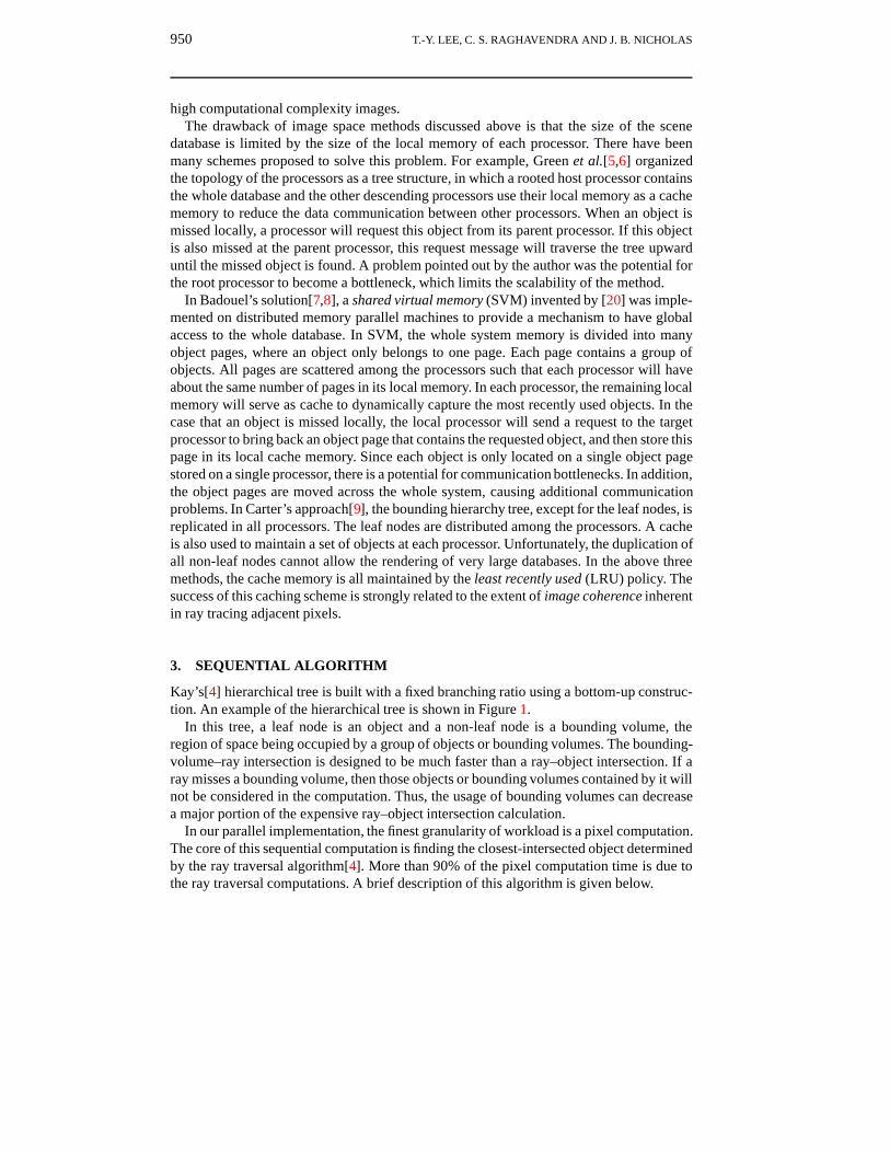
Kay’s[4] hierarchical tree is built with a fixed branching ratio using a bottom-up construc-tion. An example of the hierarchical tree is shown in Figure 1.
In this tree, a leaf node is an object and a non-leaf node is a bounding volume, theregion of space being occupied by a group of objects or bounding volumes. The bounding-volume–ray intersection is designed to be much faster than a ray–object intersection. If aray misses a bounding volume, then those objects or bounding volumes contained by it willnot be considered in the computation. Thus, the usage of bounding volumes can decreasea major portion of the expensive ray–object intersection calculation.
In our parallel implementation, the finest granularity of workload is a pixel computation.The core of this sequential computation is finding the closest-intersected object determinedby the ray traversal algorithm[4]. More than 90% of the pixel computation time is due tothe ray traversal computations. A brief description of this algorithm is given below.
IMPLEMENTATION OF A RAY TRACING ALGORITHM 951
Bounding Volume Object Primitive
Root
Figure 1. A hierarchical bounding volume tree
Ray traversal algorithmAn incoming rayt =∞p = nil
while the heap is non-empty and the distance to top node < tExtract a candidate node from the heapif this candidate node is a leaf
Compute the ray-primitive intersectionif the ray hits this candidate node and the distance < t
t = distancep = candidate node
endifelse
for each child of the candidate nodeCompute the ray-bounding volume intersectionif the ray hits the bounding volume
Insert the child into the heapendif
endforendif
endwhile
For each ray, we start with a ray traversal from the root of the tree and a priorityqueue implemented via a heap structure is used to order the bounding volume tests. Onlythose children nodes intersected with the ray will be considered further. This traversal willcontinue recursively and will terminate when either no intersections with objects are found,or the closest bounding volume on the top of queue has a larger estimated distance thanthat of currently found intersected object.
4. INTEL TOUCHSTONE DELTA PARALLEL COMPUTER
We performed our implementation on the Intel Touchstone Delta machine. The Delta isa high-speed concurrent multicomputer, consisting of an ensemble of 512 computational

952 T.-Y. LEE, C. S. RAGHAVENDRA AND J. B. NICHOLAS
nodes arranged as a 16×32 mesh[21]. The nodes are Intel i860 microprocessors, each withits own memory space. Groups of nodes can work on the same problem and communicatewith each other by message passing. The Delta architecture has three kinds of messagepassing methods: synchronous, asynchronous and interrupt handler.
5. PARALLEL IMPLEMENTATION OF RAY TRACING ALGORITHM
The problem in our ray tracing parallelization is to find an optimal load and databasedistribution such that the parallel execution cost for the independent task t0, t1, . . . , tn−1
on N processors is minimum. Each ti is the task to calculate the (R,G,B) value at theith pixel on the image screen. The total execution cost of a task ti on the processor isCti +CCti , whereCti is the processing cost of executing ti on a processor andCCti is thecommunication cost incurred by executing ti on that scheduled processor. In our cost model,the communication cost includes the overheads incurred in scheduling ti and in fetchingremote data required by ti. The computational characteristics of tis and their patterns ofdata access cannot be predicted until runtime. Finding an optimal data distribution is verydifficult, and therefore only heuristic approaches can be employed for this class of problems.The main steps of our parallel implementation are the following:
Parallel implementation of ray tracingstep0: Host parses database file and does database partition.step1: Load data onto the memory of the processors.step2: Construct the hierarchical tree extents.step3: Ray trace the assigned pixel regions.step4: Collect rendered results and display image.
The heuristic methods used in our implementation are given in the following subsections.
5.1. Database partitioning and distribution
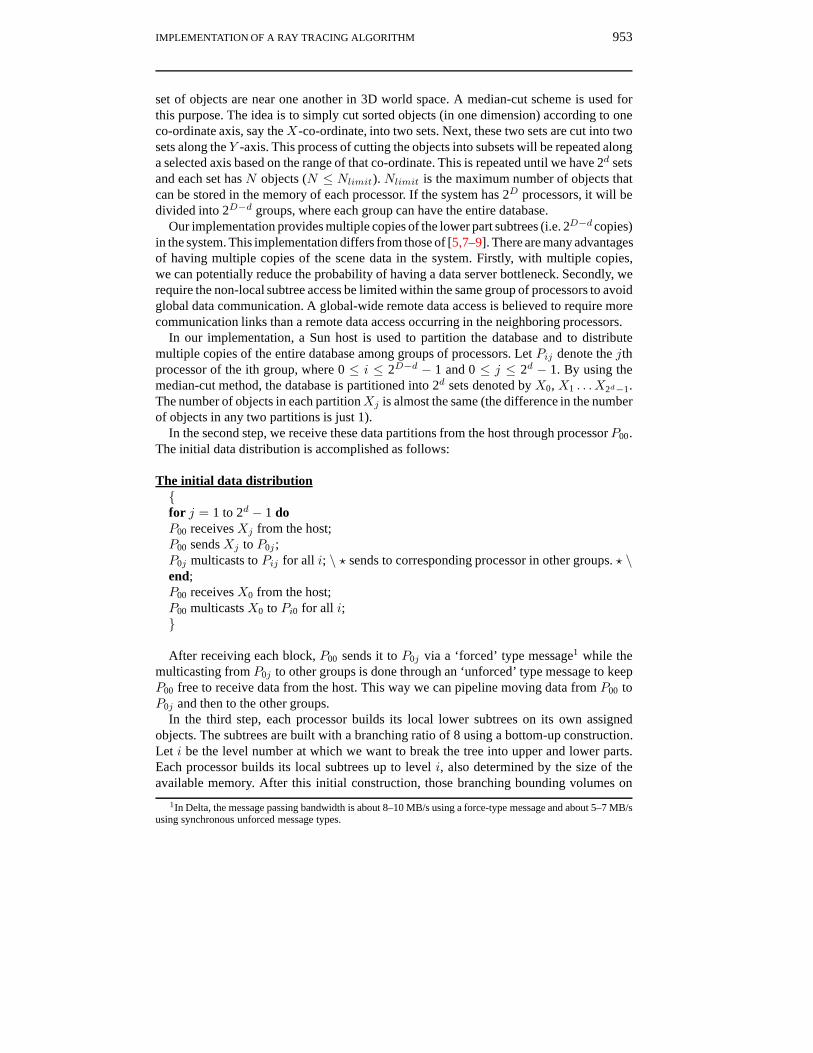
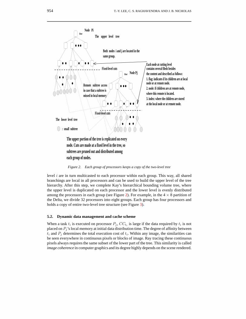
In our implementation, the scene is represented by a hierarchical bounding volume treestructure. To compute the (R,G,B) values for a pixel, the ray traversal algorithm is used toparse this tree structure. It can be seen that bounding volumes near the root node will betested against an incoming ray more often than nodes at lower levels. As the ray intersectiontesting moves down the tree, the number of objects or bounding volumes tested againstwill be smaller. Therefore, it is expected that the major portion of the intersections of raytracing will occur in the upper part of the tree hierarchy. We also know that the storagerequirements increase exponentially as we travel down the tree. The lower portion of thetree is responsible for more than 90% of the total memory requirements. Therefore, wedecided to duplicate all bounding volumes of the upper part of the tree in each processor(which will be referenced more frequently) and hold only a small portion of the lower partin each processor. Using this distribution, we remove the cost of fetching the upper part ofthe tree from CCti . Later, we describe the cache scheme to decrease the cost of accessingthe lower part of the tree. Since there is no prior way to decide which part of the lowerlevel tree is used most frequently, the best way is to distribute these lower level subtreesevenly among the processors. To achieve this initial data distribution, three steps are used.
In the first step, the whole database is sorted and partitioned into 2d sets, where each
IMPLEMENTATION OF A RAY TRACING ALGORITHM 953
set of objects are near one another in 3D world space. A median-cut scheme is used forthis purpose. The idea is to simply cut sorted objects (in one dimension) according to oneco-ordinate axis, say theX-co-ordinate, into two sets. Next, these two sets are cut into twosets along the Y -axis. This process of cutting the objects into subsets will be repeated alonga selected axis based on the range of that co-ordinate. This is repeated until we have 2d setsand each set has N objects (N ≤ Nlimit). Nlimit is the maximum number of objects thatcan be stored in the memory of each processor. If the system has 2D processors, it will bedivided into 2D−d groups, where each group can have the entire database.
Our implementation provides multiple copies of the lower part subtrees (i.e. 2D−d copies)in the system. This implementation differs from those of [5,7–9]. There are many advantagesof having multiple copies of the scene data in the system. Firstly, with multiple copies,we can potentially reduce the probability of having a data server bottleneck. Secondly, werequire the non-local subtree access be limited within the same group of processors to avoidglobal data communication. A global-wide remote data access is believed to require morecommunication links than a remote data access occurring in the neighboring processors.
In our implementation, a Sun host is used to partition the database and to distributemultiple copies of the entire database among groups of processors. Let Pij denote the jthprocessor of the ith group, where 0 ≤ i ≤ 2D−d − 1 and 0 ≤ j ≤ 2d − 1. By using themedian-cut method, the database is partitioned into 2d sets denoted by X0, X1 . . . X2d−1.The number of objects in each partitionXj is almost the same (the difference in the numberof objects in any two partitions is just 1).
In the second step, we receive these data partitions from the host through processorP00.The initial data distribution is accomplished as follows:
The initial data distribution{for j = 1 to 2d − 1 doP00 receives Xj from the host;P00 sends Xj to P0j ;P0j multicasts to Pij for all i; \ ? sends to corresponding processor in other groups. ? \end;P00 receives X0 from the host;P00 multicasts X0 to Pi0 for all i;}
After receiving each block, P00 sends it to P0j via a ‘forced’ type message1 while themulticasting from P0j to other groups is done through an ‘unforced’ type message to keepP00 free to receive data from the host. This way we can pipeline moving data from P00 toP0j and then to the other groups.
In the third step, each processor builds its local lower subtrees on its own assignedobjects. The subtrees are built with a branching ratio of 8 using a bottom-up construction.Let i be the level number at which we want to break the tree into upper and lower parts.Each processor builds its local subtrees up to level i, also determined by the size of theavailable memory. After this initial construction, those branching bounding volumes on
1In Delta, the message passing bandwidth is about 8–10 MB/s using a force-type message and about 5–7 MB/susing synchronous unforced message types.
954 T.-Y. LEE, C. S. RAGHAVENDRA AND J. B. NICHOLAS
3. index: where the children are stored
Root
Root
The upper level tree
The lower level tree
Remote subtree access
: small subtree
Fixed-level cuts
Fixed-level cuts
Node Pi
Node Pj
Both nodes i and j are located in the same group.
in case that a subtree ismissed in local memory
The upper portion of the tree is replicated on every
each group of nodes.subtrees are pruned out and distributed among node. Cuts are made at a fixed level in the tree, so
Each node at cutting levelcontains several fileds besidesthe content and described as follows:
node or at remote node.
where this remote is located.
at the local node or at remote node.
1. flag: indicates if its children are at local
2. node: if children are at remote node,
Figure 2. Each group of processors keeps a copy of the two-level tree
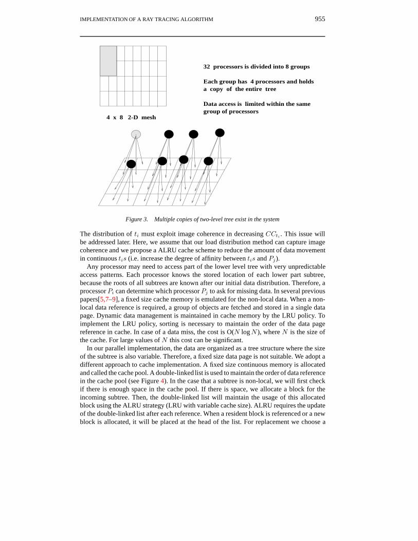
level i are in turn multicasted to each processor within each group. This way, all sharedbranchings are local in all processors and can be used to build the upper level of the treehierarchy. After this step, we complete Kay’s hierarchical bounding volume tree, wherethe upper level is duplicated on each processor and the lower level is evenly distributedamong the processors in each group (see Figure 2). For example, in the 4× 8 partition ofthe Delta, we divide 32 processors into eight groups. Each group has four processors andholds a copy of entire two-level tree structure (see Figure 3).
5.2. Dynamic data management and cache scheme
When a task ti is executed on processor Pj , CCti is large if the data required by ti is notplaced onPj’s local memory at initial data distribution time. The degree of affinity betweenti and Pj determines the total execution cost of ti. Within any image, the similarities canbe seen everywhere in continuous pixels or blocks of image. Ray tracing these continuouspixels always requires the same subset of the lower part of the tree. This similarity is calledimage coherence in computer graphics and its degree highly depends on the scene rendered.
IMPLEMENTATION OF A RAY TRACING ALGORITHM 955
a copy of the entire tree
32 processors is divided into 8 groups
Each group has 4 processors and holds
Data access is limited within the same group of processors
4 x 8 2-D mesh
Figure 3. Multiple copies of two-level tree exist in the system
The distribution of ti must exploit image coherence in decreasing CCti . This issue willbe addressed later. Here, we assume that our load distribution method can capture imagecoherence and we propose a ALRU cache scheme to reduce the amount of data movementin continuous tis (i.e. increase the degree of affinity between tis and Pj).
Any processor may need to access part of the lower level tree with very unpredictableaccess patterns. Each processor knows the stored location of each lower part subtree,because the roots of all subtrees are known after our initial data distribution. Therefore, aprocessor Pi can determine which processor Pj to ask for missing data. In several previouspapers[5,7–9], a fixed size cache memory is emulated for the non-local data. When a non-local data reference is required, a group of objects are fetched and stored in a single datapage. Dynamic data management is maintained in cache memory by the LRU policy. Toimplement the LRU policy, sorting is necessary to maintain the order of the data pagereference in cache. In case of a data miss, the cost is O(N logN ), where N is the size ofthe cache. For large values of N this cost can be significant.
In our parallel implementation, the data are organized as a tree structure where the sizeof the subtree is also variable. Therefore, a fixed size data page is not suitable. We adopt adifferent approach to cache implementation. A fixed size continuous memory is allocatedand called the cache pool. A double-linked list is used to maintain the order of data referencein the cache pool (see Figure 4). In the case that a subtree is non-local, we will first checkif there is enough space in the cache pool. If there is space, we allocate a block for theincoming subtree. Then, the double-linked list will maintain the usage of this allocatedblock using the ALRU strategy (LRU with variable cache size). ALRU requires the updateof the double-linked list after each reference. When a resident block is referenced or a newblock is allocated, it will be placed at the head of the list. For replacement we choose a

956 T.-Y. LEE, C. S. RAGHAVENDRA AND J. B. NICHOLAS
A cache pool:
S 1 S2 S3 S i+1 Si+2S i
Header
Tail
Double-linked list
Each item in double-linked list is a pointer to a corresponding subtree S i
a nonlocal subtree Si is temporily stored in a cache pool
and is maintained by a double-linked list.
Figure 4. Dynamic data management for non-local subtrees
cache block starting from the tail of the list. Therefore, using ALRU, blocks in the cachelist are always in the most to least recently referenced order, without the exact sortingoverhead incurred in LRU (see Figure 5). However, ALRU needs to adjust the pointerswhen a reference is made to each cache block.
The ALRU cache scheme is adopted to capture the most recently used non-local subtrees.It can greatly reduce CCtis for executing continuous tis tasks with a stronger degree ofimage coherence. However, the degree of image coherence depends on many factors, suchas the scene data and view point. It is difficult to model this effect formally; therefore, it ishard to find the best cache size automatically for any scene. However, the key to selecting
points to S j
Old header
New header old tail
old tail
a block reference
Update after any block reference
points to Sk
points to Sk
points to S i points to St
points to Stpoints to S i
points to S j
In double-linked list, each subtree S is always kept in
most to least recently referenced order
Figure 5. ALRU policy
IMPLEMENTATION OF A RAY TRACING ALGORITHM 957
a good cache is to make sure that the cache is large enough to hold the lower part of thesubtrees for a given ray that is assigned to each processor. This will at least avoid thrashingin the cache system. In Kay’s ray traversal algorithm in the worst case, a ray will travelthrough all lower subtrees. Fortunately, this is very rare in real data. We will show the effectof cache size on performance in our discussion of the experimental performance evaluationsection.
5.3. Efficient data movement strategy
Next, we need to decide the most efficient size of the subtree to be transferred at one time.It is not wise to transfer the subtree whole at one time. This can exhaust the cache pool veryquickly and may result in unnecessary cache block swapping. In the ray traversal algorithm,if a bounding volume is hit, the ray will test against all of its children (eight children in ourimplementation). In a message passing system such as the Intel Delta, there is a higher cost incommunication setup time, plus a smaller cost for each byte transferred. In order to decreasethe overall cost of message passing, long messages are preferred. Therefore, it makes senseto transfer all the children at one time, rather than one by one. We need to know the optimalmessage size, and to this end we measured the time necessary for transferring data fromone node to another in the Delta. In our implementation, a processor uses asynchronoussend/receive to request data servers, which use message handler routines to transfer therequested data. We measured this round trip time experimentally by the following steps:
The measure of round trip timeNodei: starts the clock; sends a request to Nodej (i 6= j).Nodej: as the request message arrives, a message handler routine sends reply message
back.Nodei: stops the clock after receiving the reply.
We tested different sizes of reply message varying from 1K to 512K bytes and averagedover 10,000 runs. The round trip time cost (in µs) can be modeled by:
Cost(l) = 286.4 + 0.133l (1)
In Equation (1), 286.4 µs is the setup time for this round trip and its cost is a factor 0.133of the message size l. Each non-leaf bounding volume needs 100 bytes of storage in ourimplementation. Hence, we let:
• T (1) = Cost(8 × 100) and is the time to transfer eight children of one boundingvolume at one time (i.e. 81). This single level subtree is called S(1).• T (2) = Cost(72 × 100) and is the time to transfer a 2-level bounding volume
subtree, which is called S(2) at one time (i.e. 81 + 82).• T (n) is the time to transfer an n-level bounding volume subtree, which is called
S(n), at one time.
We find the condition when it is efficient to transfer messages by S(2) rather than multipleS(1) messages by the equation:
T (2) ≤ T (1) + k × T (1) (2)

958 T.-Y. LEE, C. S. RAGHAVENDRA AND J. B. NICHOLAS
We find k ≥ 2.163, which means that if more than two of eight bounding volumes onone level are hit, we should use S(2). The probability that Equation (2) is true is high, so weadopt S(2). To transfer subtree S(n ≥ 3) as a message, the storage requirements increasesexponentially and it is hard to predict their future usage. Thus, we consider the S(2) subtreeto be the most reasonable size. Therefore, in our tree representation, each subtree of thelower part of the tree hierarchy is decomposed into many S(2) subtrees. Each S(2) subtreeis stored in continuous storage and is ready to be fetched. Traveling S(2) by the depth-firstor breadth-first order, S(2) can be stored easily in continuous storage. Each element of S(2)contains the index of each child by which it can find a specific child in this storage.
5.4. Load distribution and load balancing
Our load distribution has two steps: a static load initialization where image coherence isconsidered, and a run time load redistribution which smoothes out load imbalances incurredin the first step. In the first step, givenN processors, the image screen is partitioned into Nrectangular subimages of comparable size. Each subimage is further subdivided into fixedsquare regions which are the units of load redistribution. The first step attempts to give aroughly balanced load among processors. More importantly, in each subimage, pixels arecontinuous or regions are close in 2D. Therefore, better image coherence is maintained andthe possibility of non-local data movement is reduced. For load redistribution, square pixelregions are preferred in that they have more potential for exploiting image coherence thanthe long and skinny rectangular regions[10]. After the database and initial load distribution,each processor begins to ray trace its allocated subimage. At run time, a load balancingscheme is used to achieve a global balanced load.
1 2 3
8 10 11
assigned to Processor i
7
i Region
Screen space
45
12131415
9
0
6
Figure 6. Snake mapping assignment
We logically organize theN processors of the Intel Delta in a ring topology (see an exam-ple in Figure 6). Two neighboring processors will be assigned two neighboring subimages,also due to image coherence. When a particular node becomes idle, say Pi, it requestsextra work from successive nodes on the ring, Pi+1, . . . , PN , P1, . . . , Pi−1, until it finds anode that is busy. This busy node, say Pj , dispatches a square pixel region (a× a) to thisrequest. The node Pi will remember that node Pj was the last node from which a requestwas made. The next time it is idle, it will start requesting work from node Pj , bypassingnodes between Pi and Pj . An additional feature of this strategy is that if, in the meantime,node Pj becomes idle and Pj remembers that it received work from node Pk, node Pi will
IMPLEMENTATION OF A RAY TRACING ALGORITHM 959
jump from Pj directly to Pk without asking for work from nodes between Pj and Pk. Inthis strategy, node Pi stops its search for work if it ends up at itself or at some node that ithas already visited or skipped in a search step. This ensures that the search will end whenall nodes are idle.
In our implementation, the initial subimage is stored at the task queue of the processorallocated that subimage. Each processor will fetch an a× a (a bundle of tis pixels) regionfor execution at one time. When it becomes idle, it will try to find an extra a × a regionfrom other busy processors along the ring. The size of the a× a region is used to controlthe granularity of the load distribution. This size depends greatly on the scene rendered andother factors, and it is hard to find the optimal value for all images. From our experiencewith test scenes, the optimal size ranges from 4× 4 to 8× 8.
6. EXPERIMENTAL RESULTS AND DISCUSSIONS
We used a set of standard scenes from Eric Haines’s database to perform our experimentalevaluation[22]. Table 1 shows the geometric characteristics of three scenes. These testscenes have been used in many previous studies and are believed to be a good representationof real data[6,7].
Table 1. Database characteristics
Scene Number of triangles Number of light sources
Ball 157441 3Mountain 33536 1Tree 57122 7
To evaluate our scheme, we make the assumption that the maximum available memorysize to store the database is 4 MB. This size is about 0.25 times the available memorysize of each processor on the Delta. This allows us to experiment with distributing thedatabase. We divide this 4 MB into two parts: 2.5 MB (called PM) is used to store both theentire upper level tree and part of the lower level subtrees, while 1.5 MB (CM) is used ascache memory. In this configuration, the maximum number of primitives is approximately6000 triangles and the number of bounding volumes on the cutting level is less than 4096(84 = 4096). Table 2 shows how we store three test scenes. In this table, the memoryrequirement is the size of the whole hierarchical tree, N -way is the number of processorsrequired to store the whole tree, and the ratio is CM over the memory requirement. Of thethree scenes, the Balls scenes is the largest, and the available cache memory is small. Thesmall cache can potentially lead to more data communication overhead in the processingof rays.
Table 2. Data distribution for three test scenes
Scenes Balls Tree Mountain
Memory requirement, bytes 48404088 17074408 10124216N -way 32 16 8Ratio of CM to total memory requirement, % 3.25 9.2 15.5
960 T.-Y. LEE, C. S. RAGHAVENDRA AND J. B. NICHOLAS
0.98
1
1.02
1.04
1.06
1.08
1.1
1.12
1.14
1.16
2 3 4 5 6 7 8 9 10
*
* *
*
*
o
oo
o
o
+
+
+
+
+
Pixel size used for load sharing
Rela
tive P
rocess
or
x T
ime
Mountain : - + - +
Tree : - o - o
Balls : - * - *
Normalized line: - - - -
Figure 7. Relative time for 3 scenes for different square region sizes (pixel size × pixel size).
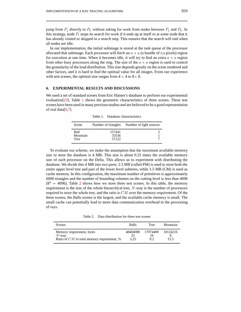
In our experimental evaluation, several key parameters affect the performance of ourparallel ray tracer. These parameters include the size of the square region used in load sharingamong processors, the type of load balancing scheme employed, the size of software cachein each processor, and the number of copies of the entire database (group size). In order tostudy scalability, we ran our experiments on the Delta machine using 16 to 512 nodes. Allrendering timings are for an image size of 512× 512 with no anti-aliasing. Unless statedotherwise, the following values are used in the experimentation: 2.5 MB for PM, 1.5 MBfor CM and 4× 4 for a region size. If we do not need the entire 2.5 MB for PM, then theremaining memory is also allocated to CM.
The results of our experiments regarding pixel region size used in load sharing areshown in Figure 7. For each region size selected, we ran experiments with the number ofprocessors varying from 16 to 512. We calculated the total processor time product (PT) as∑9i=4 or 5 2iT2i , where T2i is the time taken for parallel rendering with 2i processors. The
total processor time product with a 4 × 4 pixel region is used to normalize the results ofother region sizes. As evidenced by Figure 7, the parallel rendering time was best for allthree scenes with a small size square region for load sharing; a region size in the range4× 4 to 8× 8 gives the best overall performance for the three scenes studied.
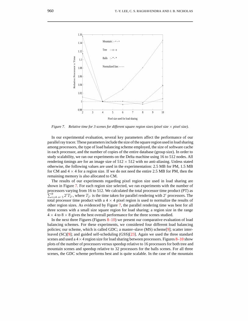
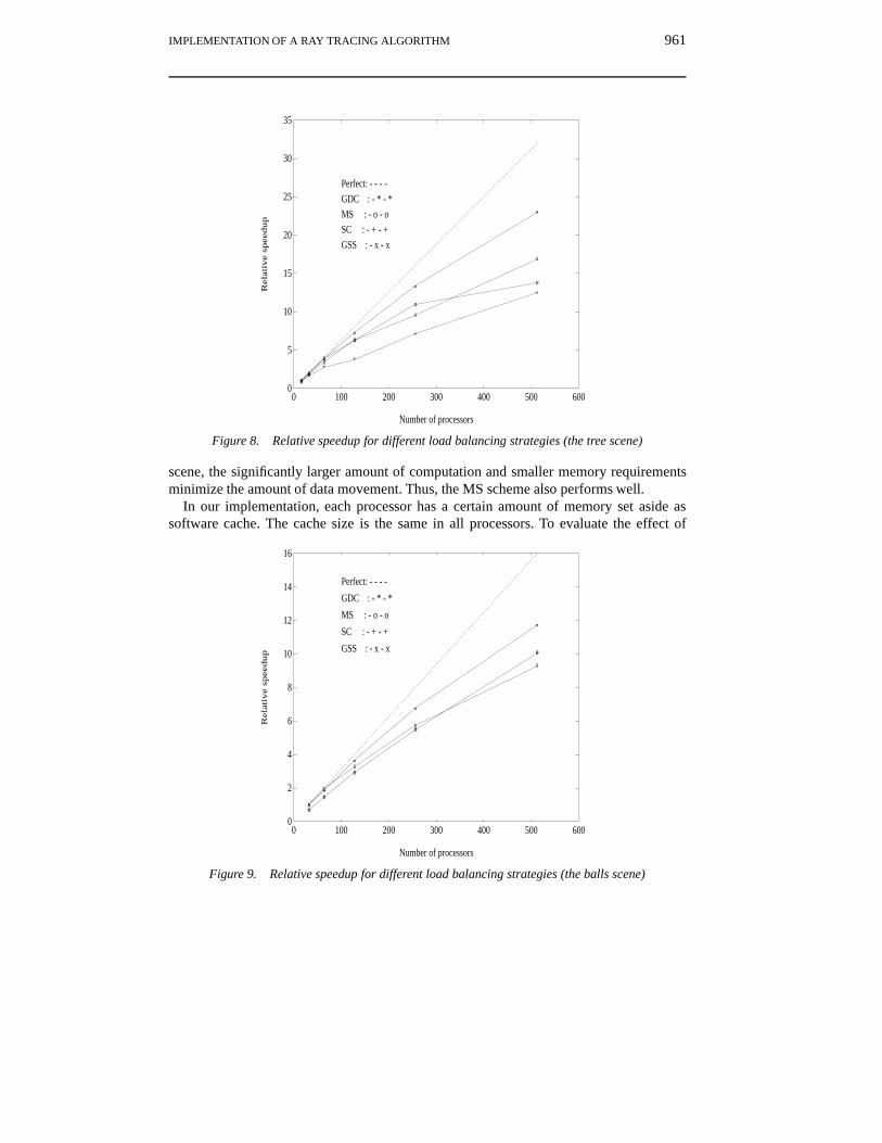
In the next three Figures (Figures 8–10) we present our comparative evaluation of loadbalancing schemes. For these experiments, we considered four different load balancingpolicies; our scheme, which is called GDC; a master–slave (MS) scheme[9]; scatter inter-leaved (SC)[9]; and guided self-scheduling (GSS)[23]. Again we used the three standardscenes and used a 4×4 region size for load sharing between processors. Figures 8–10 showplots of the number of processors versus speedup relative to 16 processors for both tree andmountain scenes and speedup relative to 32 processors for the balls scenes. For all threescenes, the GDC scheme performs best and is quite scalable. In the case of the mountain
IMPLEMENTATION OF A RAY TRACING ALGORITHM 961
0
5
10
15
20
25
30
35
0 100 200 300 400 500 600
**
*
*
*
*
oo
o
o
o
o
++
++
+
+
xx
x
x
x
x
Number of processors
Rela
tive s
peedup
Perfect: - - - -
GDC : - * - *
MS : - o - o
SC : - + - +
GSS : - x - x
Figure 8. Relative speedup for different load balancing strategies (the tree scene)
scene, the significantly larger amount of computation and smaller memory requirementsminimize the amount of data movement. Thus, the MS scheme also performs well.
In our implementation, each processor has a certain amount of memory set aside assoftware cache. The cache size is the same in all processors. To evaluate the effect of
0
2
4
6
8
10
12
14
16
0 100 200 300 400 500 600
*
*
*
*
*
o
o
o
o
o
+
+
+
+
+
x
x
x
x
x
Number of processors
Rela
tive s
peedup
Perfect: - - - -
GDC : - * - *
MS : - o - o
SC : - + - +
GSS : - x - x
Figure 9. Relative speedup for different load balancing strategies (the balls scene)
962 T.-Y. LEE, C. S. RAGHAVENDRA AND J. B. NICHOLAS
0
5
10
15
20
25
30
35
0 100 200 300 400 500 600
**
*
*
*
*
oo
o
o
o
o
++
+
+
+
+
xx
x
x
x
x
Number of processors
Rela
tive s
peedup
Perfect: - - - -
GDC : - * - *
MS : - o - o
SC : - + - +
GSS : - x - x
Figure 10. Relative speedup for different load balancing strategies (the mountain scene)
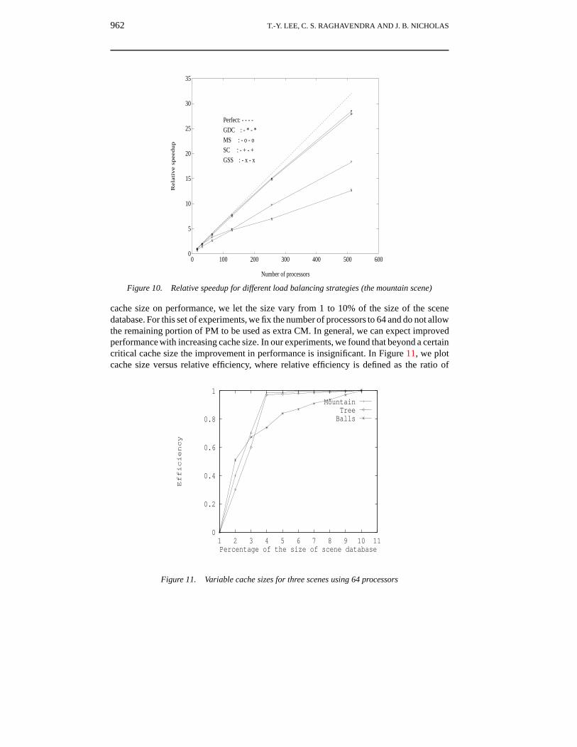
cache size on performance, we let the size vary from 1 to 10% of the size of the scenedatabase. For this set of experiments, we fix the number of processors to 64 and do not allowthe remaining portion of PM to be used as extra CM. In general, we can expect improvedperformance with increasing cache size. In our experiments, we found that beyond a certaincritical cache size the improvement in performance is insignificant. In Figure 11, we plotcache size versus relative efficiency, where relative efficiency is defined as the ratio of
0
0.2
0.4
0.6
0.8
1
1 2 3 4 5 6 7 8 9 10 11
Efficiency
Percentage of the size of scene database
MountainTree
Balls
Figure 11. Variable cache sizes for three scenes using 64 processors
IMPLEMENTATION OF A RAY TRACING ALGORITHM 963
0.8
0.85
0.9
0.95
1
1.05
0 100 200 300 400 500 600
o o oo
o o
*
** *
*
*
++
+ + +
+
Number of processors
Impro
vem
ent
rati
o
Mountain: - + - +
Tree : - o - o
Balls : - * - *
Reference line: - - - -
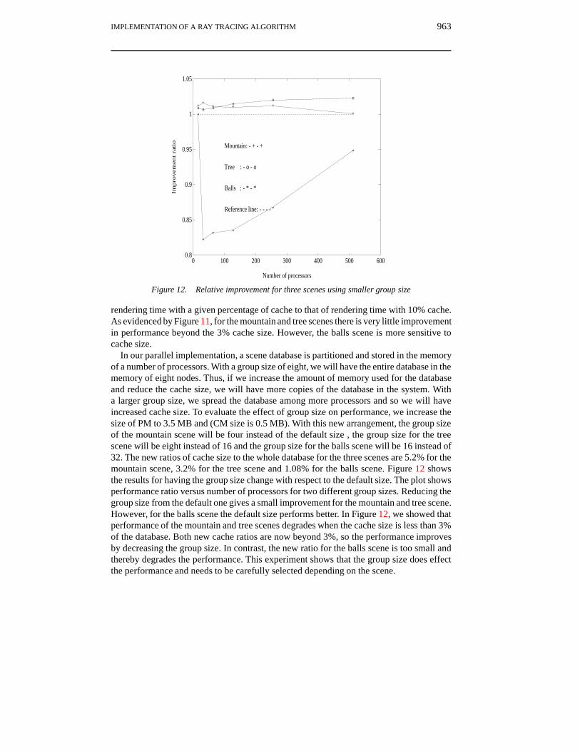
Figure 12. Relative improvement for three scenes using smaller group size
rendering time with a given percentage of cache to that of rendering time with 10% cache.As evidenced by Figure 11, for the mountain and tree scenes there is very little improvementin performance beyond the 3% cache size. However, the balls scene is more sensitive tocache size.
In our parallel implementation, a scene database is partitioned and stored in the memoryof a number of processors. With a group size of eight, we will have the entire database in thememory of eight nodes. Thus, if we increase the amount of memory used for the databaseand reduce the cache size, we will have more copies of the database in the system. Witha larger group size, we spread the database among more processors and so we will haveincreased cache size. To evaluate the effect of group size on performance, we increase thesize of PM to 3.5 MB and (CM size is 0.5 MB). With this new arrangement, the group sizeof the mountain scene will be four instead of the default size , the group size for the treescene will be eight instead of 16 and the group size for the balls scene will be 16 instead of32. The new ratios of cache size to the whole database for the three scenes are 5.2% for themountain scene, 3.2% for the tree scene and 1.08% for the balls scene. Figure 12 showsthe results for having the group size change with respect to the default size. The plot showsperformance ratio versus number of processors for two different group sizes. Reducing thegroup size from the default one gives a small improvement for the mountain and tree scene.However, for the balls scene the default size performs better. In Figure 12, we showed thatperformance of the mountain and tree scenes degrades when the cache size is less than 3%of the database. Both new cache ratios are now beyond 3%, so the performance improvesby decreasing the group size. In contrast, the new ratio for the balls scene is too small andthereby degrades the performance. This experiment shows that the group size does effectthe performance and needs to be carefully selected depending on the scene.
964 T.-Y. LEE, C. S. RAGHAVENDRA AND J. B. NICHOLAS
7. CONCLUSIONS
In this paper, we presented experimental results for a load balanced, distributed memoryparallel ray tracer on the Intel Delta. Several important parameters affect the performanceof parallel ray tracing with a distributed database. Our implementation uses a hierarchicaltree decomposition approach to store the scene database in a group of processors. We de-veloped the software cache scheme to take advantage of locality in pixel computations, andthus improve the performance. Experiments were conducted extensively to investigate thescalability of various parameters on the performance of parallel ray tracer. Our conclusionsare that there is a critical cache size which depends on the scene being rendered, and thatthere is an optimal group size and region size in load sharing for a given scene. In ourearlier work, we developed the GDC load balancing policy for ray tracing with each nodehaving a copy of the database[3]. Here, we showed that GDC with some modification alsoperforms well and is scalable for a distributed database.
ACKNOWLEDGEMENTS
This research was performed in part using the Intel Touchstone Delta System operated byCalifornia Institute of Technology on behalf of the Concurrent Supercomputing Consor-tium. Access to this facility was provided by Pacific Northwest Laboratory, a multipurposenational laboratory which is operated for the US Department of Energy by Battelle Memo-rial Institute under contract DE-AC06-76RLO 1830. This research is supported by theBoeing Centennial Chair Professor funds.
REFERENCES
1. Turner, ‘An improved illumination model for shaded display’, Commun. ACM, 23, (6), (1980).2. An Introduction to Ray Tracing, A. S. Glassner (Ed.), Academic Press, 1989.3. T. Lee, C. S. Raghavendra and J. B. Nicholas, ‘Experimental evaluation of load balancing strate-
gies for ray tracing on parallel processors’, in International Conference on Parallel Processing,1994.
4. T. L. Kay and J. T. Kajiya, ‘Ray tracing complex scenes’, ACM SIGGRAPH 1986, August 1986.5. S. Green et al., ‘Exploiting coherence for multiprocessor ray tracing’, IEEE Comput. Graph.
Appl., 9, (6), (1989).6. S. Green, Parallel Processing for Computer Graphics, MIT Press, 1991.7. Badouel et al., ‘Ray tracing on distributed memory parallel computers’, SIGGRAPH 1990.8. Badouel et al., ‘Distributed data and control for ray tracing in parallel’, IEEE Comput. Graph.
Appl., July 1994.9. M. B. Carter and K. A. Teague, ‘The hypercube ray tracer’, in Proc. of the 5th Distributed
Memory Computing Conference, 1990.10. S. Whitman, Multiprocessor Methods for Computer Graphics Rendering, Jones and Bartlett,
1992.11. M. Dippe and J. Swensen, ‘An adaptive subdivision algorithm and parallel architecture for
realistic image synthesis’, Comput. Graphics, (July 1984).12. K. Nemoto and T. Omachi, ‘An adaptive subdivision by sliding boundary surfaces for fast ray
tracing’, in Proceedings of Graphics Interface ’86, 1986.13. H. Kobayashi et al., ‘Parallel processing of an object space for image synthesis using ray tracing’,
Vis. Comput., 2, (1), (1987).14. K. Bouatoch and T. Priol, ‘Parallel space tracing: An experience on an iPSC hypercube’, in
N. Magnenat-Thalmann and D. Thalmann (Eds.),New Trends in Computer Graphics, 1988.15. D. A. J. Jevans, ‘Optimistic multi-processor ray tracing’, in R. A. Earnshaw and B. Wyvill
(Eds.), New Advances in Computer Graphics, Springer Verlag, 1989.
IMPLEMENTATION OF A RAY TRACING ALGORITHM 965
16. M. J. Muuss RT and REMRT, ‘Shared memory parallel and network distributed ray tracingprograms’, Proc. USENIX Assoc. Comput. Graph. Workshop, 1987.
17. J. Packer, ‘Exploiting concurrency: a ray tracing example’, in The Transputer ApplicationNotebook, Inmos, 1989.
18. D. May, Toward General Purpose Parallel Computers, MIT Press, Cambridge, 1989.19. M. Potmesil et al., ‘A parallel image computer with distributed frame buffer: system architecture
and programming’, in Eurographics 89, North Holland, Hamburg, 1989.20. K. Li, Shared Virtual Memory on Loosely Couple Multiprocessor, PhD dissertation, Yale Univ.,
1986.21. Touchstone Delta User’s Guide, Intel Corporation, October 1991.22. E. Haines, ‘A proposal for standard graphics environments’, IEEE Comput. Graph. Appl.,7, (4),
(1987).23. C. Polychronopoulos et al., ‘Guided self-scheduling: A practical scheduling scheme for parallel
computers’, IEEE Trans. Comput., (12), (1987).