Embed Size (px)
Citation preview
John Mellor-Crummey
Department of Computer Science Rice University
Parallel Computing Platforms Network Topologies
COMP 422/534 Lecture 14 28 February 2017
2
Topics for Today
Interconnection networks
• Taxonomy
• Metrics
• Topologies
• Characteristics —cost —performance
3
Interconnection Networks
• Carry data —between processors —between processors and memory
• Interconnect components —switches —links (wires, fiber)
• Interconnection network flavors —static networks: point-to-point communication links
– AKA direct networks —dynamic networks: switches and communication links
– AKA indirect networks
4
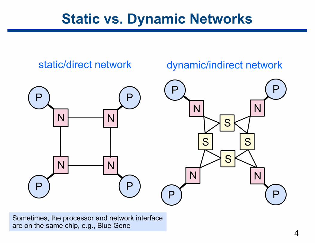
Static vs. Dynamic Networks
P P
P P
NN
NN
static/direct network dynamic/indirect network
P
N
P
N
P
N
P
N
S
SSS
Sometimes, the processor and network interface are on the same chip, e.g., Blue Gene
5
Dynamic Network Switch
• Maps a fixed number of inputs to outputs
• Number of ports on a switch = degree of the switch
• Switch cost —grows as the square of switch degree —packaging cost grows linearly with the number of pins
• Key property: blocking vs. non-blocking —blocking
– path from p to q may conflict with path from r to s for independent p, q, r, s
—non-blocking – disjoint paths between each pair of independent sources and sinks
6
Network Interface
Processor node’s link to the interconnect
• Network interface responsibilities — packetizing communication data — computing routing information — buffering incoming/outgoing data
• Network interface connection — I/O: e.g., Peripheral Component Interface Express (PCIe) — memory: e.g., AMD HyperTransport, Intel QuickPath
– higher bandwidth and tighter coupling than I/O bus
• Network performance — depends on relative speeds of I/O and memory links
Network Topologies
• Many network topologies
• Tradeoff: performance vs. cost
• Machines often implement hybrids of multiple topologies —why?
– packaging – cost – available components
7
Metrics for Interconnection Networks
• Degree —number of links per node
• Diameter —longest distance between two nodes in the network
• Bisection width —min # of wire cuts to divide the network in 2 halves
• Cost: —~ # links and switches
8
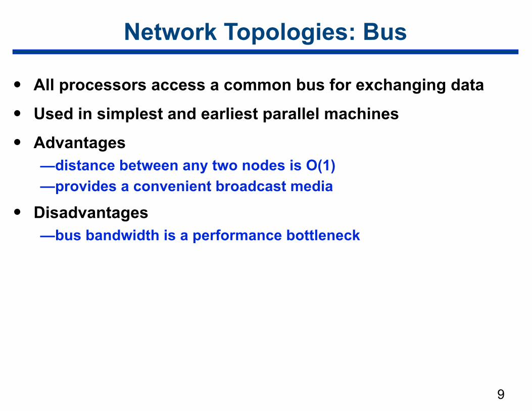
Network Topologies: Bus
• All processors access a common bus for exchanging data
• Used in simplest and earliest parallel machines
• Advantages —distance between any two nodes is O(1) —provides a convenient broadcast media
• Disadvantages —bus bandwidth is a performance bottleneck
9
10
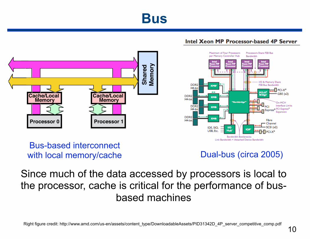
Bus
Bus-based interconnect with local memory/cache
Since much of the data accessed by processors is local to the processor, cache is critical for the performance of bus-
based machines
Right figure credit: http://www.amd.com/us-en/assets/content_type/DownloadableAssets/PID31342D_4P_server_competitive_comp.pdf
Dual-bus (circa 2005)Sh
ared
M
emor
y
Processor 1Processor 0
Cache/LocalMemory
Cache/LocalMemory
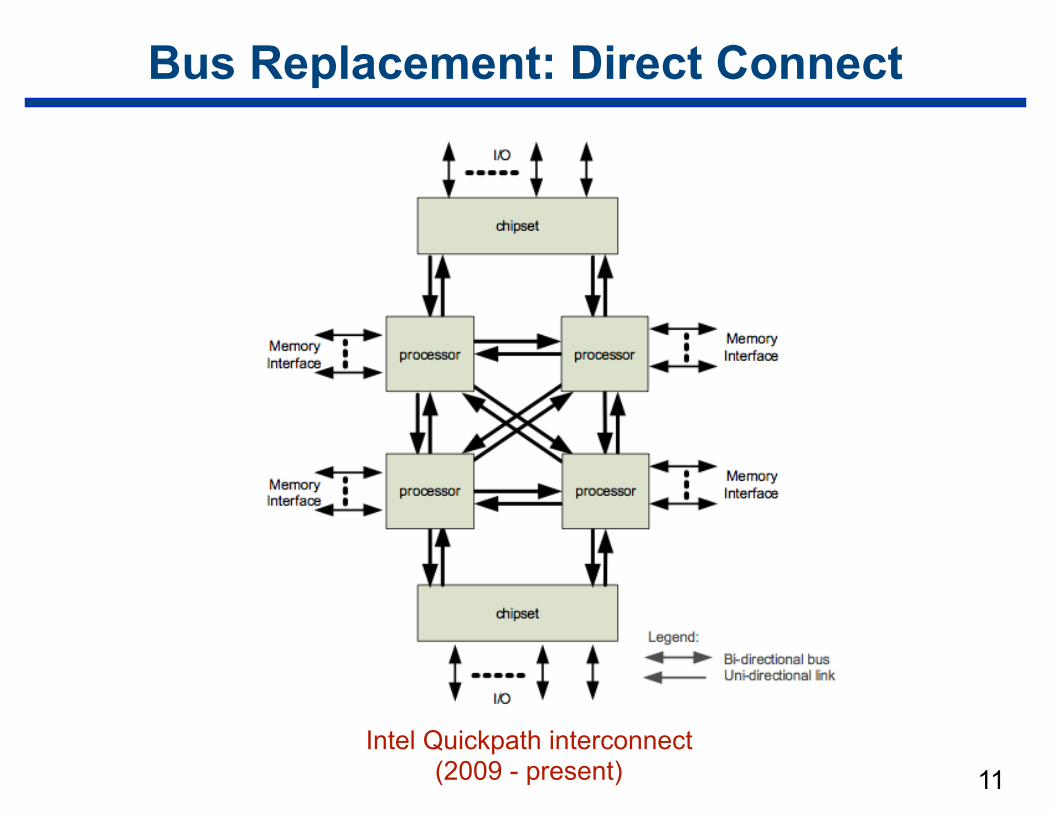
Bus Replacement: Direct Connect
11Intel Quickpath interconnect
(2009 - present)
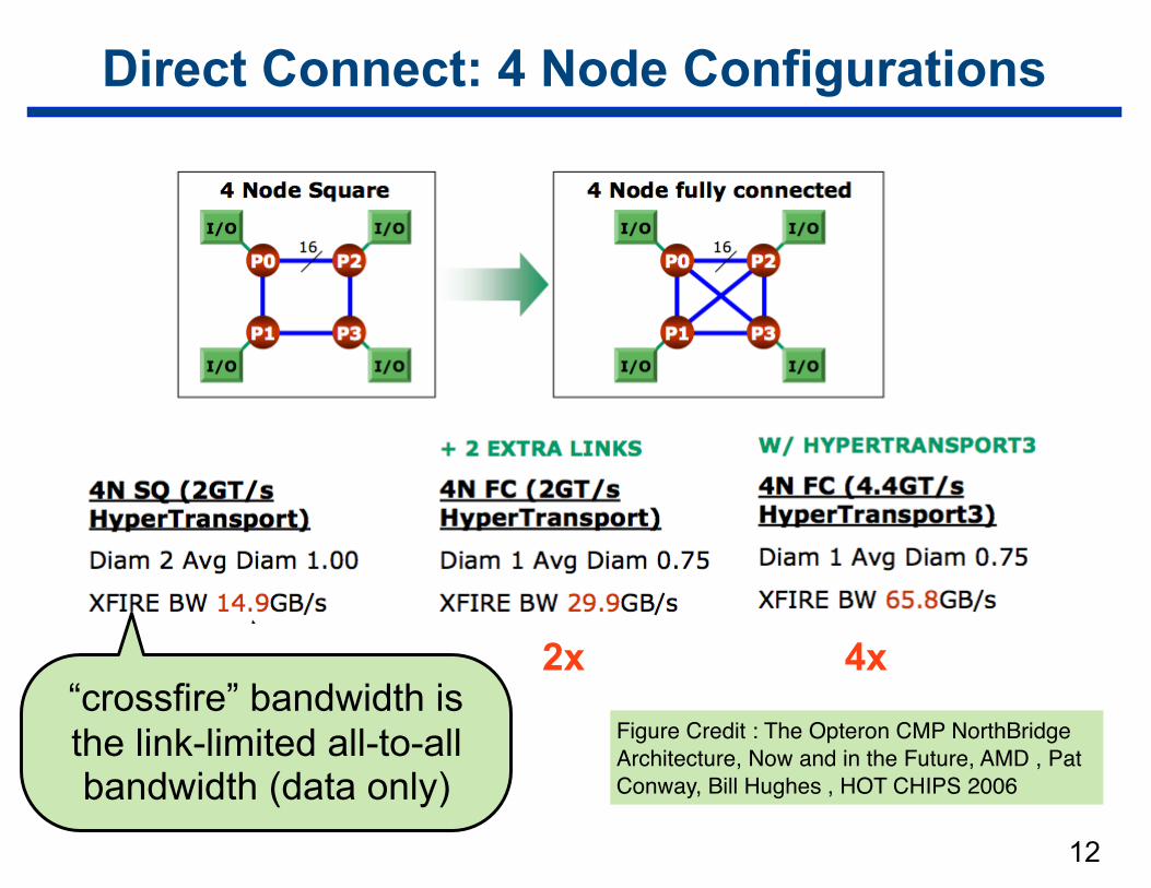
Direct Connect: 4 Node Configurations
12
2x 4x“crossfire” bandwidth is the link-limited all-to-all bandwidth (data only)
Figure Credit : The Opteron CMP NorthBridge Architecture, Now and in the Future, AMD , Pat Conway, Bill Hughes , HOT CHIPS 2006
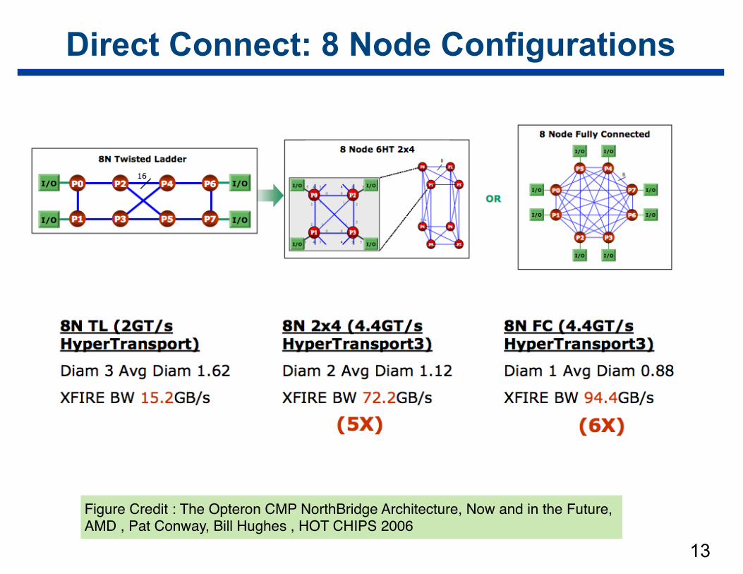
Direct Connect: 8 Node Configurations
13
Figure Credit : The Opteron CMP NorthBridge Architecture, Now and in the Future, AMD , Pat Conway, Bill Hughes , HOT CHIPS 2006
14
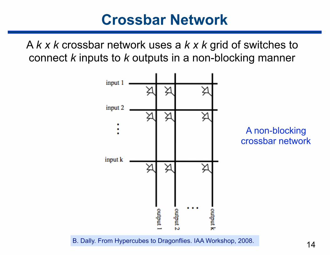
Crossbar NetworkA k x k crossbar network uses a k x k grid of switches to connect k inputs to k outputs in a non-blocking manner
A non-blocking crossbar network
B. Dally. From Hypercubes to Dragonflies. IAA Workshop, 2008.
15
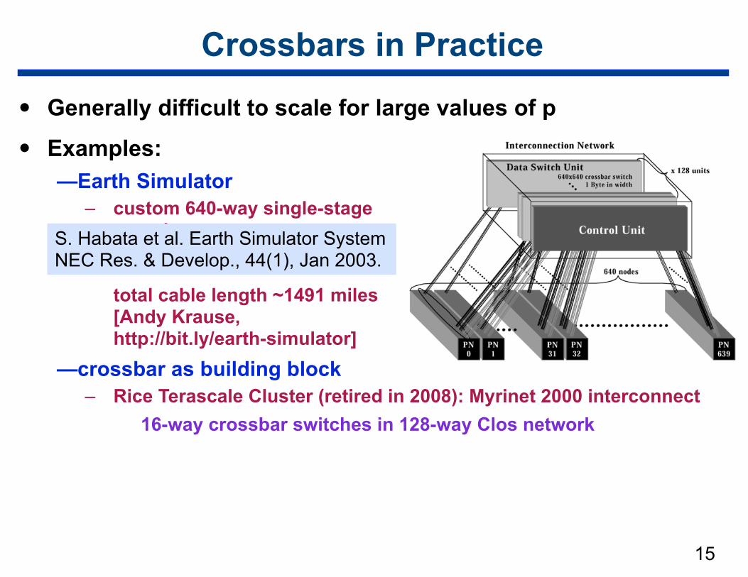
Crossbars in Practice
• Generally difficult to scale for large values of p
• Examples: —Earth Simulator
– custom 640-way single-stage crossbartotal cable length ~1491 miles [Andy Krause, http://bit.ly/earth-simulator]
—crossbar as building block – Rice Terascale Cluster (retired in 2008): Myrinet 2000 interconnect
16-way crossbar switches in 128-way Clos network
S. Habata et al. Earth Simulator System NEC Res. & Develop., 44(1), Jan 2003.
16
Assessing Network Alternatives
• Buses — excellent cost scalability — poor performance scalability
• Crossbars — excellent performance scalability — poor cost scalability
• Multistage interconnects — compromise between these extremes
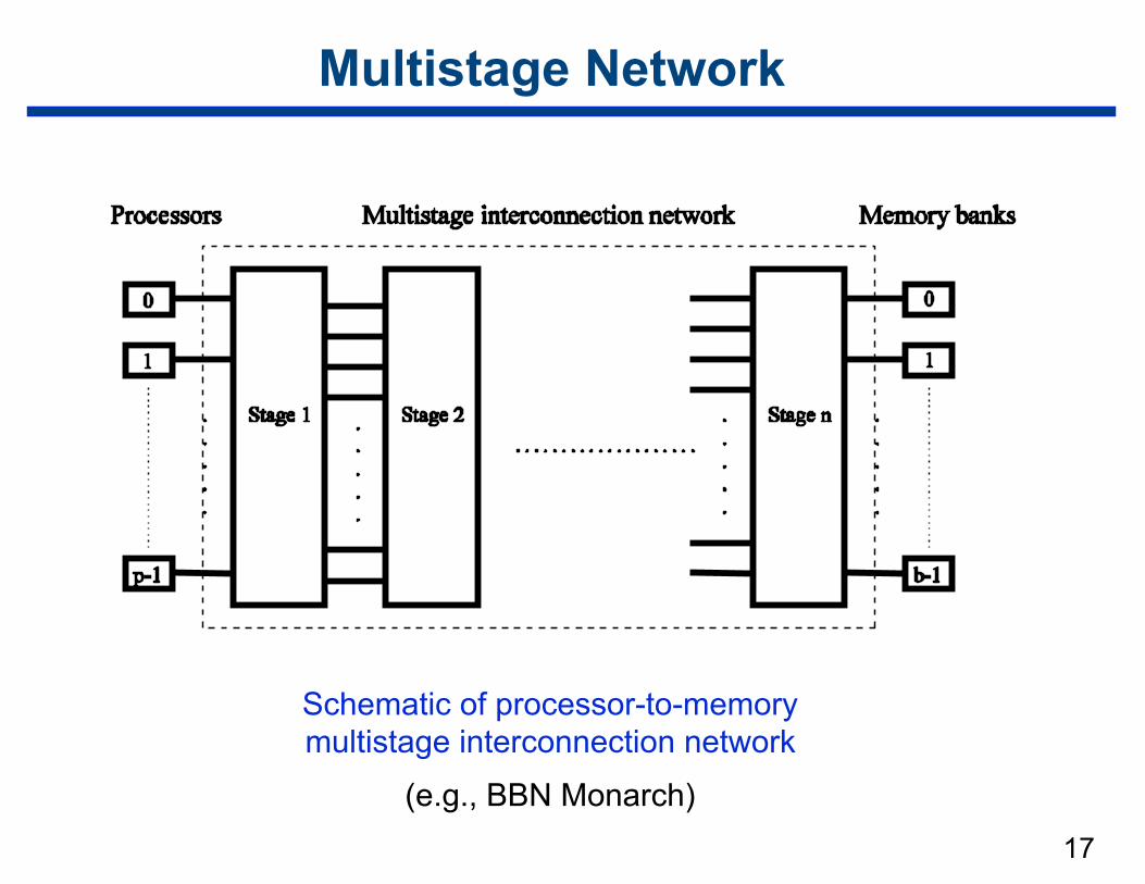
17
Multistage Network
Schematic of processor-to-memory multistage interconnection network
(e.g., BBN Monarch)
18
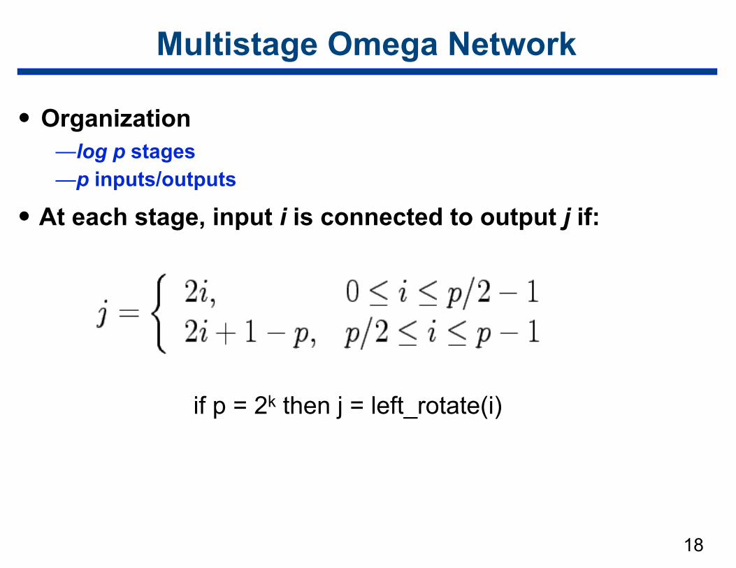
Multistage Omega Network
• Organization —log p stages —p inputs/outputs
• At each stage, input i is connected to output j if:
if p = 2k then j = left_rotate(i)
19
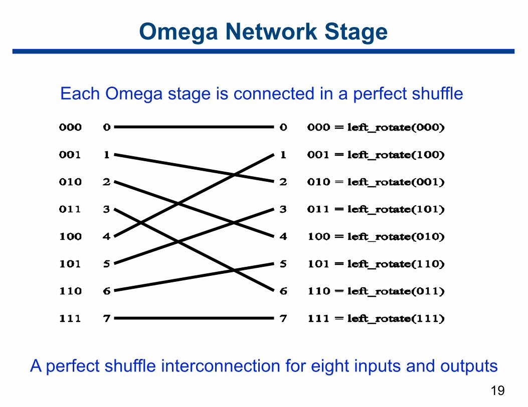
Omega Network Stage
Each Omega stage is connected in a perfect shuffle
A perfect shuffle interconnection for eight inputs and outputs
20
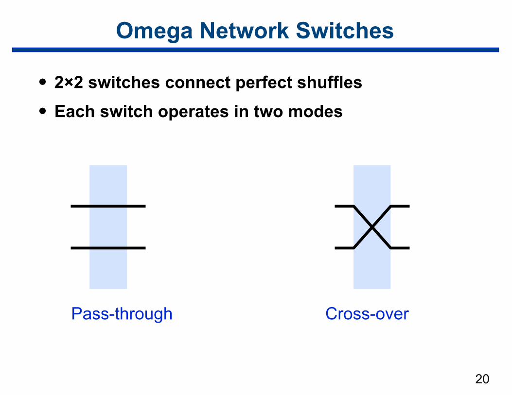
Omega Network Switches
• 2×2 switches connect perfect shuffles
• Each switch operates in two modes
Pass-through Cross-over
21
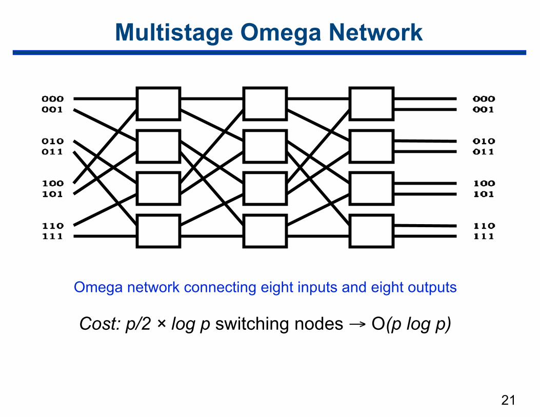
Multistage Omega Network
Omega network connecting eight inputs and eight outputs
Cost: p/2 × log p switching nodes → O(p log p)
22
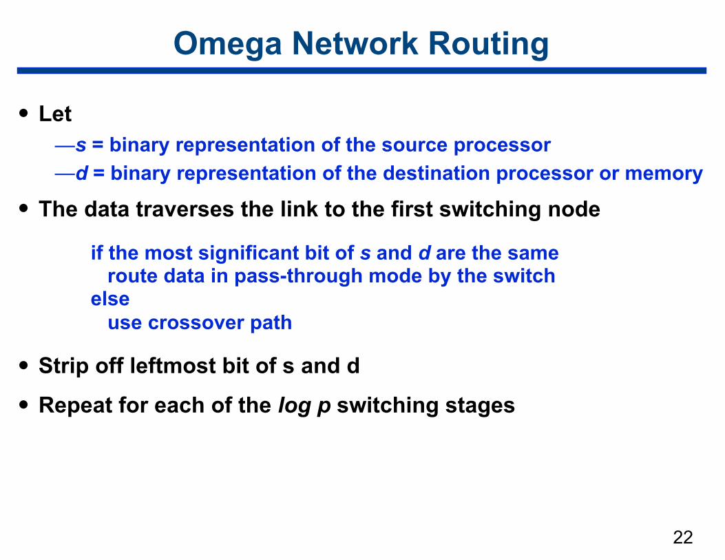
Omega Network Routing
• Let —s = binary representation of the source processor —d = binary representation of the destination processor or memory
• The data traverses the link to the first switching node
• Strip off leftmost bit of s and d
• Repeat for each of the log p switching stages
if the most significant bit of s and d are the same route data in pass-through mode by the switch else use crossover path
23
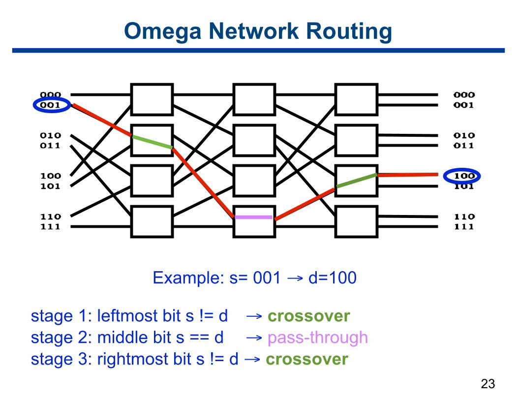
Omega Network Routing
Example: s= 001 → d=100
stage 1: leftmost bit s != d → crossover stage 2: middle bit s == d → pass-through stage 3: rightmost bit s != d → crossover
24
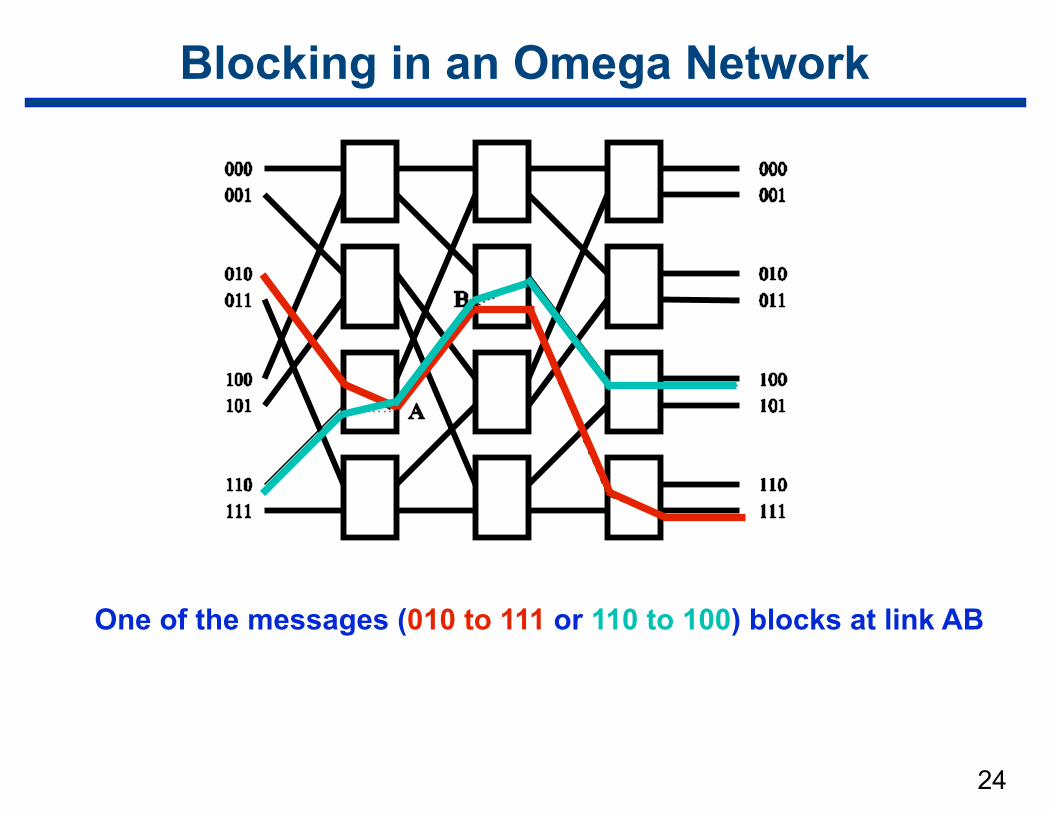
Blocking in an Omega Network
One of the messages (010 to 111 or 110 to 100) blocks at link AB
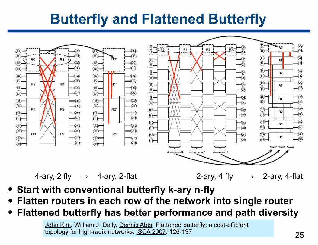
Butterfly and Flattened Butterfly
• Start with conventional butterfly k-ary n-fly • Flatten routers in each row of the network into single router • Flattened butterfly has better performance and path diversity
25
4-ary, 2 fly → 4-ary, 2-flat 2-ary, 4 fly → 2-ary, 4-flat
John Kim, William J. Dally, Dennis Abts: Flattened butterfly: a cost-efficient topology for high-radix networks. ISCA 2007: 126-137
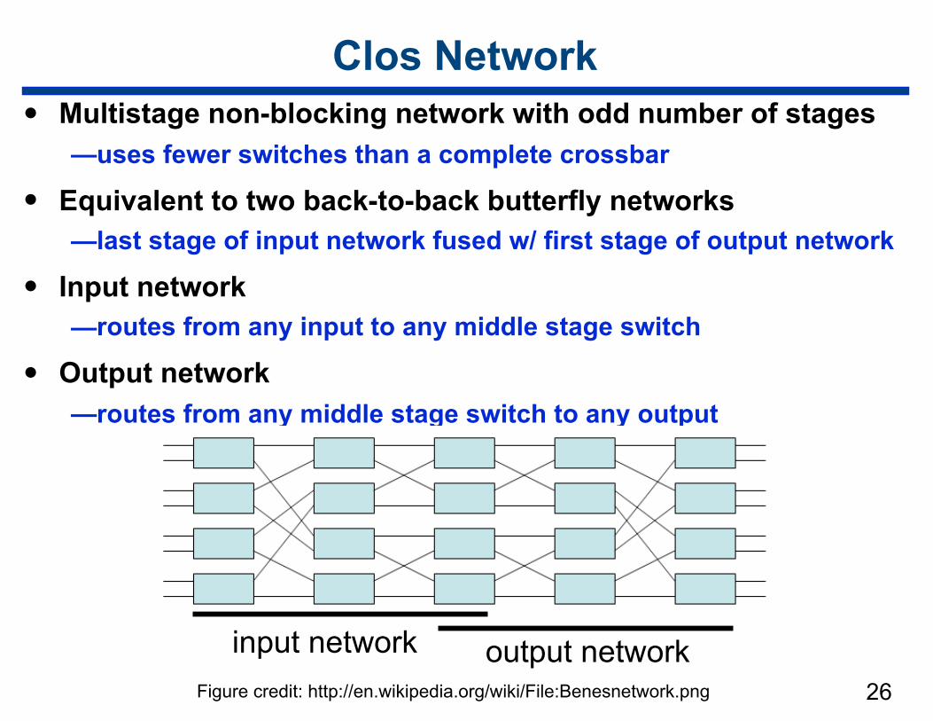
Clos Network• Multistage non-blocking network with odd number of stages
—uses fewer switches than a complete crossbar
• Equivalent to two back-to-back butterfly networks —last stage of input network fused w/ first stage of output network
• Input network —routes from any input to any middle stage switch
• Output network —routes from any middle stage switch to any output
26output networkinput network
Figure credit: http://en.wikipedia.org/wiki/File:Benesnetwork.png
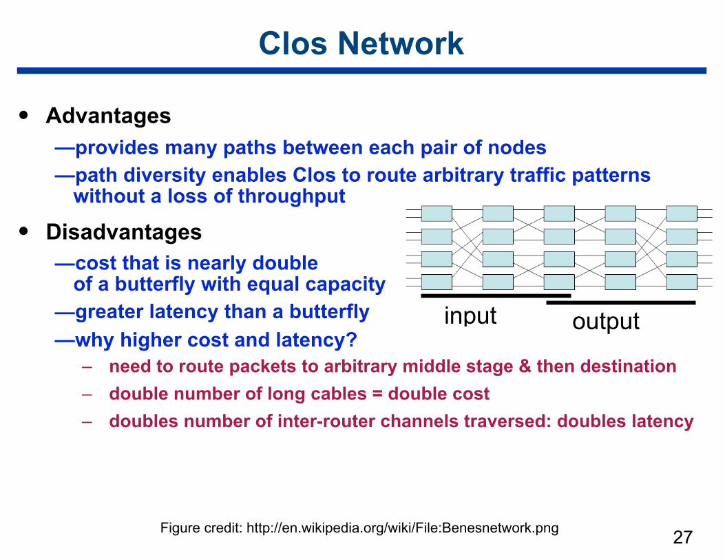
Clos Network
• Advantages —provides many paths between each pair of nodes —path diversity enables Clos to route arbitrary traffic patterns
without a loss of throughput
• Disadvantages —cost that is nearly double
of a butterfly with equal capacity —greater latency than a butterfly —why higher cost and latency?
– need to route packets to arbitrary middle stage & then destination – double number of long cables = double cost – doubles number of inter-router channels traversed: doubles latency
27
output input
Figure credit: http://en.wikipedia.org/wiki/File:Benesnetwork.png
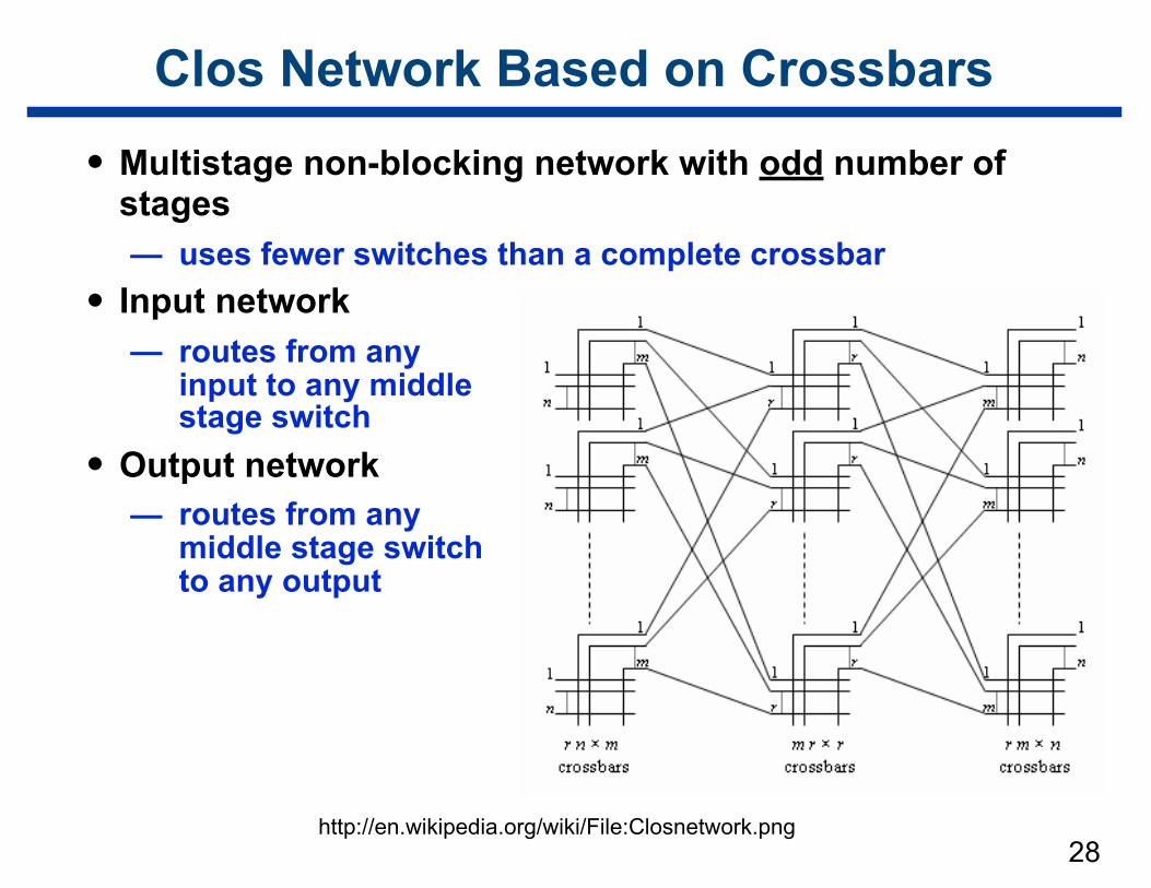
Clos Network Based on Crossbars
• Multistage non-blocking network with odd number of stages — uses fewer switches than a complete crossbar
• Input network — routes from any
input to any middle stage switch
• Output network — routes from any
middle stage switch to any output
28http://en.wikipedia.org/wiki/File:Closnetwork.png
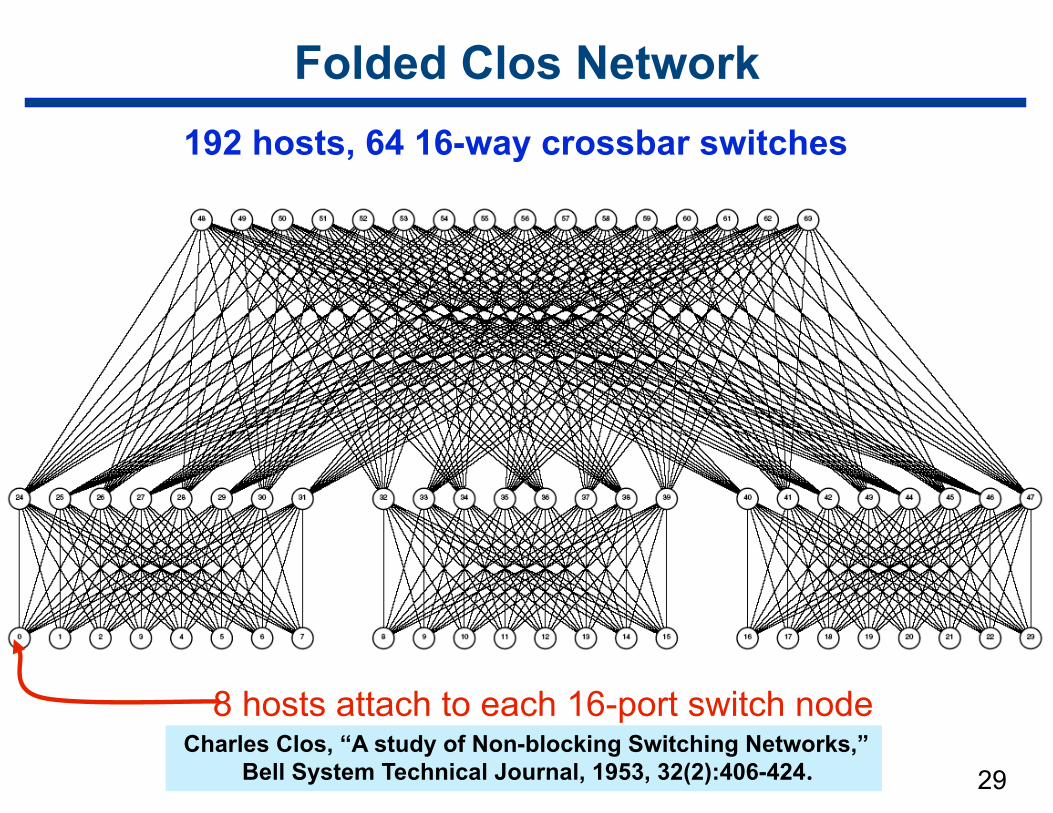
29
Folded Clos Network192 hosts, 64 16-way crossbar switches
8 hosts attach to each 16-port switch nodeCharles Clos, “A study of Non-blocking Switching Networks,”
Bell System Technical Journal, 1953, 32(2):406-424.
30
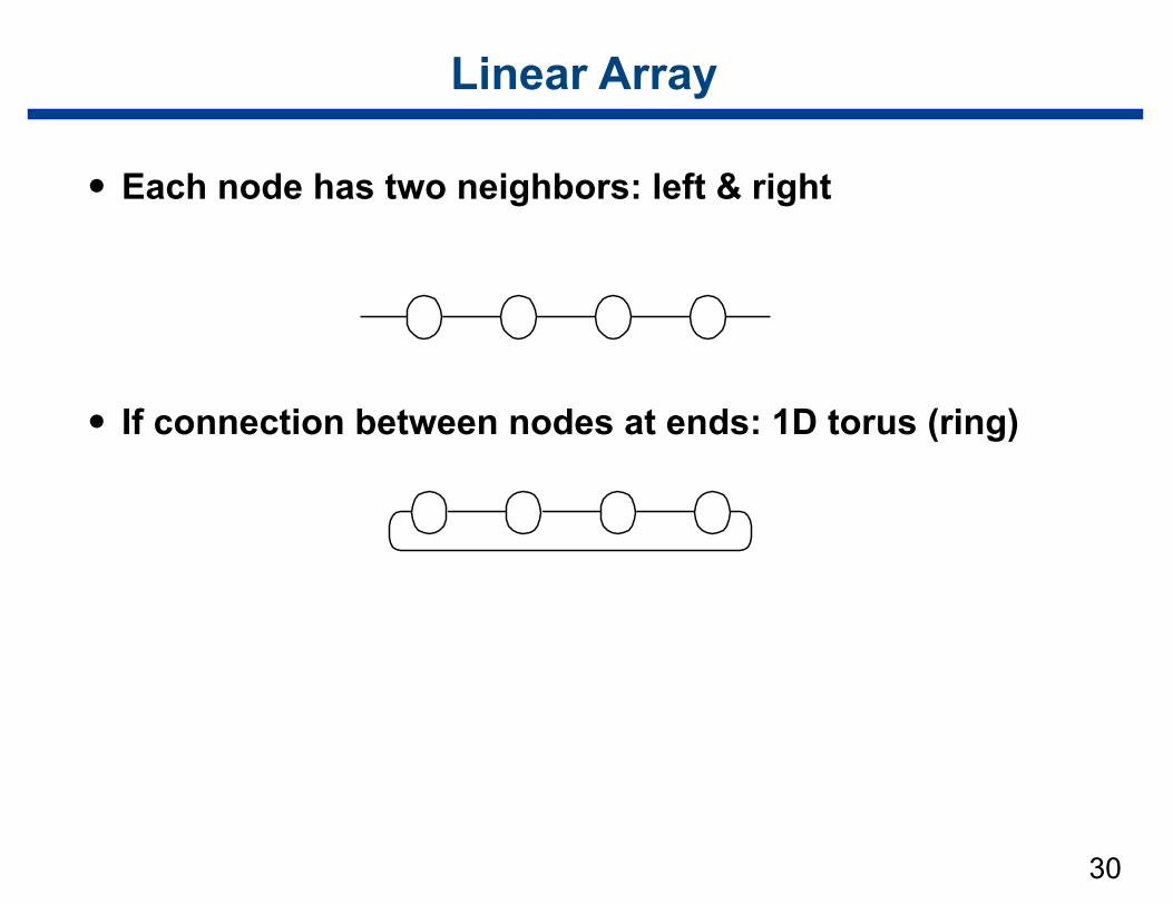
Linear Array
• Each node has two neighbors: left & right
• If connection between nodes at ends: 1D torus (ring)
31
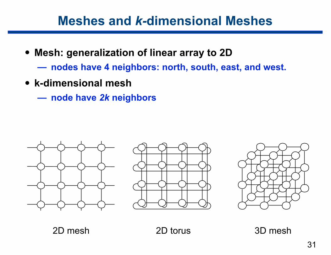
Meshes and k-dimensional Meshes
• Mesh: generalization of linear array to 2D — nodes have 4 neighbors: north, south, east, and west.
• k-dimensional mesh — node have 2k neighbors
2D mesh 2D torus 3D mesh
32
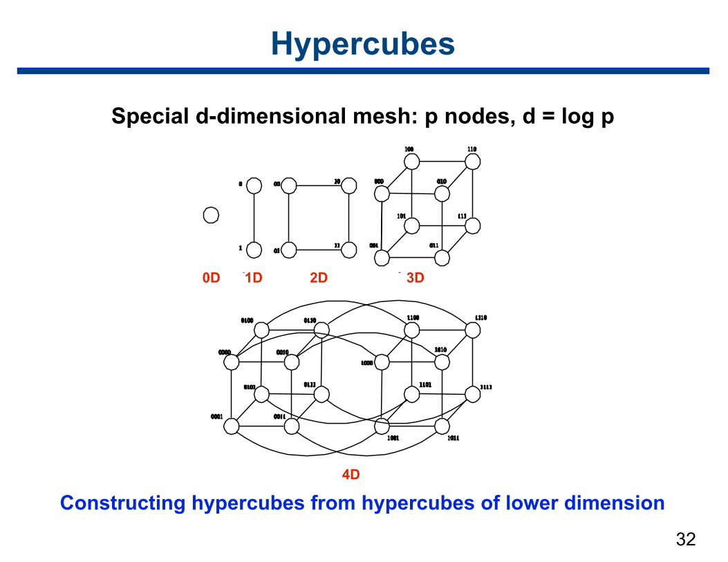
Constructing hypercubes from hypercubes of lower dimension
Hypercubes
Special d-dimensional mesh: p nodes, d = log p
0D 1D 2D 3D
4D
33
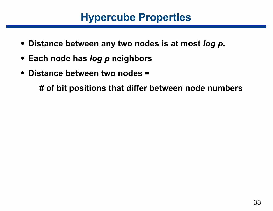
Hypercube Properties
• Distance between any two nodes is at most log p.
• Each node has log p neighbors
• Distance between two nodes =
# of bit positions that differ between node numbers
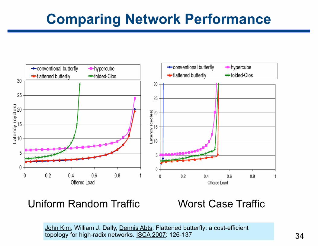
Comparing Network Performance
34
Uniform Random Traffic Worst Case Traffic
John Kim, William J. Dally, Dennis Abts: Flattened butterfly: a cost-efficient topology for high-radix networks. ISCA 2007: 126-137
35
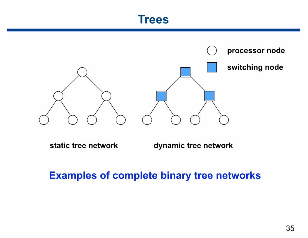
Trees
Examples of complete binary tree networks
processor node
switching node
static tree network dynamic tree network
36
Tree Properties
• Distance between any two nodes is no more than 2 log p
• Trees can be laid out in 2D with no wire crossings
• Problem — links closer to root carry > traffic than those at lower levels
• Solution: fat tree — widen links as depth gets shallower
– copes with higher traffic on links near root
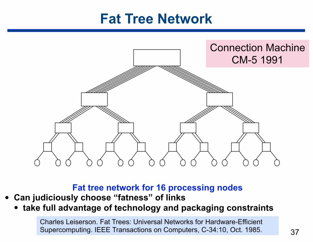
37
Fat Tree Network
Fat tree network for 16 processing nodes • Can judiciously choose “fatness” of links
• take full advantage of technology and packaging constraintsCharles Leiserson. Fat Trees: Universal Networks for Hardware-Efficient Supercomputing. IEEE Transactions on Computers, C-34:10, Oct. 1985.
Connection Machine CM-5 1991
Fat Tree Properties
“We prove that for any given amount of communications hardware, a fat-tree built from that amount of hardware can simulate every other network built from the same amount of hardware, using only slightly more time (a polylogarithmic
factor greater). The basic assumption we make of competing networks is the following. In unit time, at most O(a) bits can
enter or leave a closed 3D region with surface area a.”
This paper proves the universality result for off-line simulations only.
38
Charles Leiserson. Fat Trees: Universal Networks for Hardware-Efficient Supercomputing. IEEE Transactions on Computers, C-34:10, Oct. 1985.
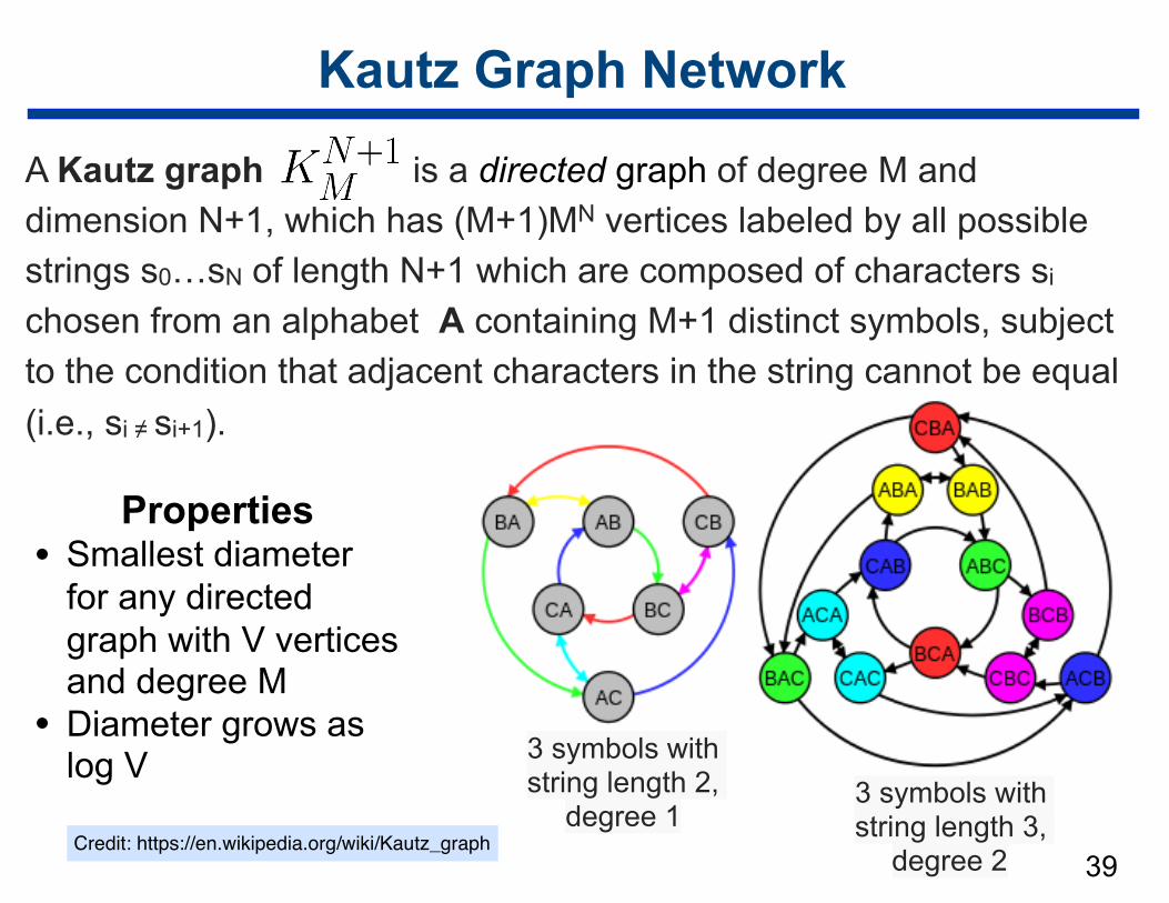
Kautz Graph Network
A Kautz graph is a directed graph of degree M and dimension N+1, which has (M+1)MN vertices labeled by all possible strings s0…sN of length N+1 which are composed of characters si chosen from an alphabet A containing M+1 distinct symbols, subject to the condition that adjacent characters in the string cannot be equal (i.e., si ≠ si+1).
39
Properties • Smallest diameter
for any directed graph with V vertices and degree M
• Diameter grows as log V 3 symbols with
string length 2, degree 1
3 symbols with string length 3,
degree 2 Credit: https://en.wikipedia.org/wiki/Kautz_graph
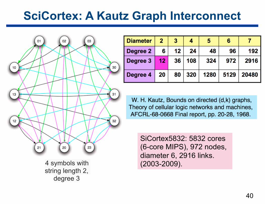
SciCortex: A Kautz Graph Interconnect
40
SiCortex5832: 5832 cores (6-core MIPS), 972 nodes, diameter 6, 2916 links. (2003-2009).4 symbols with
string length 2, degree 3

Case Study: SGI Altix UV
41
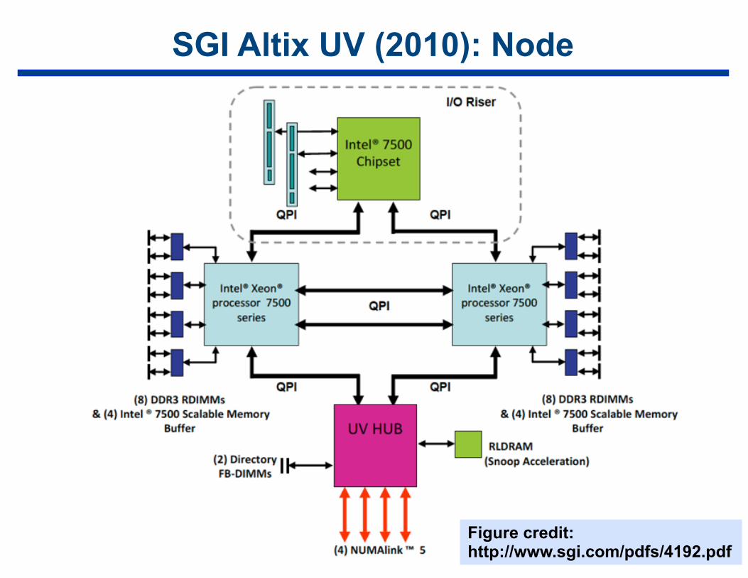
SGI Altix UV (2010): Node
42Figure credit: http://www.sgi.com/pdfs/4192.pdf
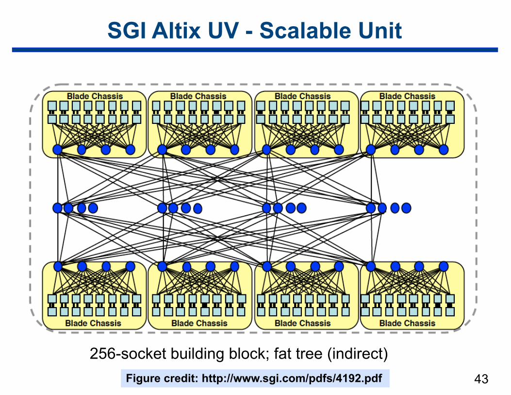
SGI Altix UV - Scalable Unit
43
256-socket building block; fat tree (indirect)Figure credit: http://www.sgi.com/pdfs/4192.pdf
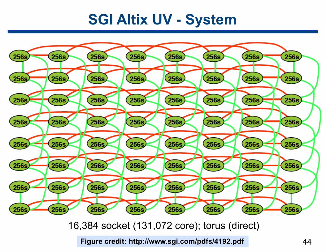
SGI Altix UV - System
44
16,384 socket (131,072 core); torus (direct)Figure credit: http://www.sgi.com/pdfs/4192.pdf
Dragonfly
45
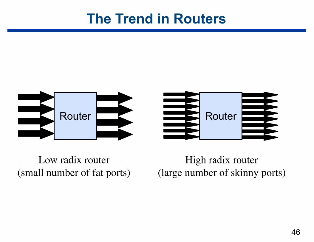
The Trend in Routers
46
Router
Low radix router(small number of fat ports)
Router
High radix router(large number of skinny ports)
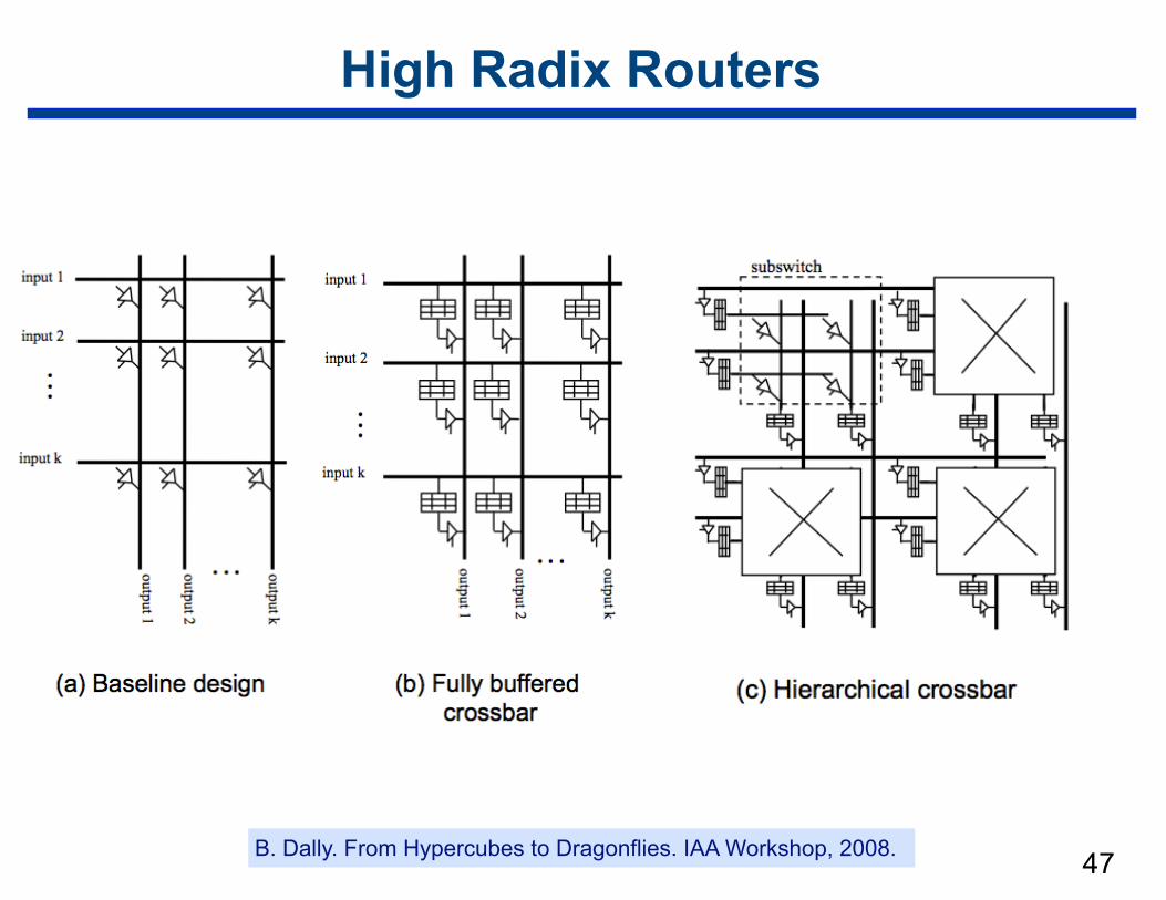
High Radix Routers
47B. Dally. From Hypercubes to Dragonflies. IAA Workshop, 2008.
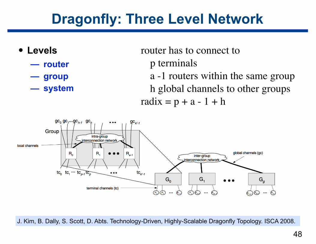
Dragonfly: Three Level Network
• Levels — router — group — system
48
router has to connect to p terminalsa -1 routers within the same grouph global channels to other groups
radix = p + a - 1 + h
J. Kim, B. Dally, S. Scott, D. Abts. Technology-Driven, Highly-Scalable Dragonfly Topology. ISCA 2008.
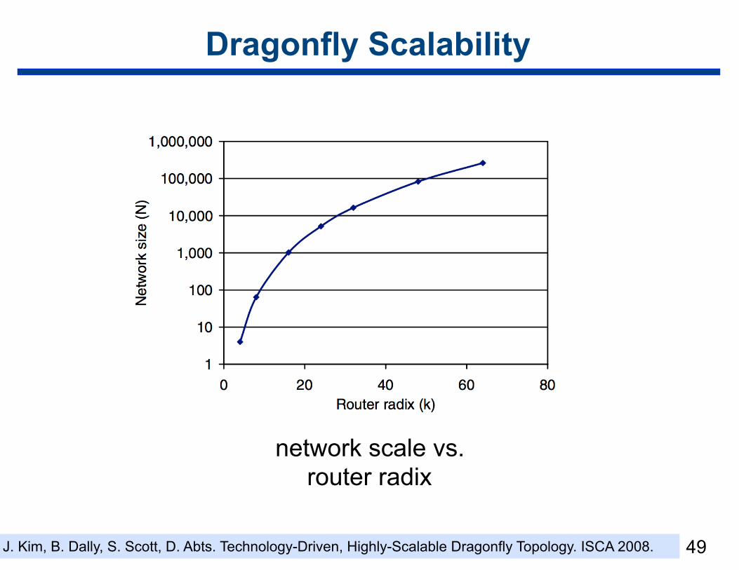
Dragonfly Scalability
49
network scale vs. router radix
J. Kim, B. Dally, S. Scott, D. Abts. Technology-Driven, Highly-Scalable Dragonfly Topology. ISCA 2008.
50
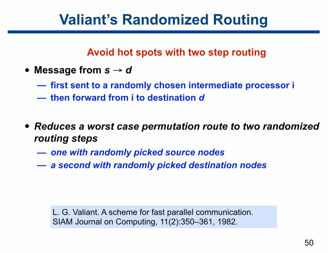
Valiant’s Randomized Routing
Avoid hot spots with two step routing
• Message from s → d — first sent to a randomly chosen intermediate processor i — then forward from i to destination d
• Reduces a worst case permutation route to two randomized routing steps — one with randomly picked source nodes — a second with randomly picked destination nodes
L. G. Valiant. A scheme for fast parallel communication. SIAM Journal on Computing, 11(2):350–361, 1982.
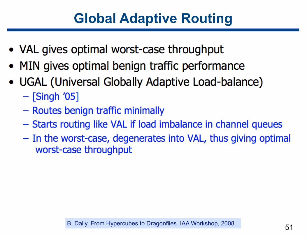
Global Adaptive Routing
51B. Dally. From Hypercubes to Dragonflies. IAA Workshop, 2008.
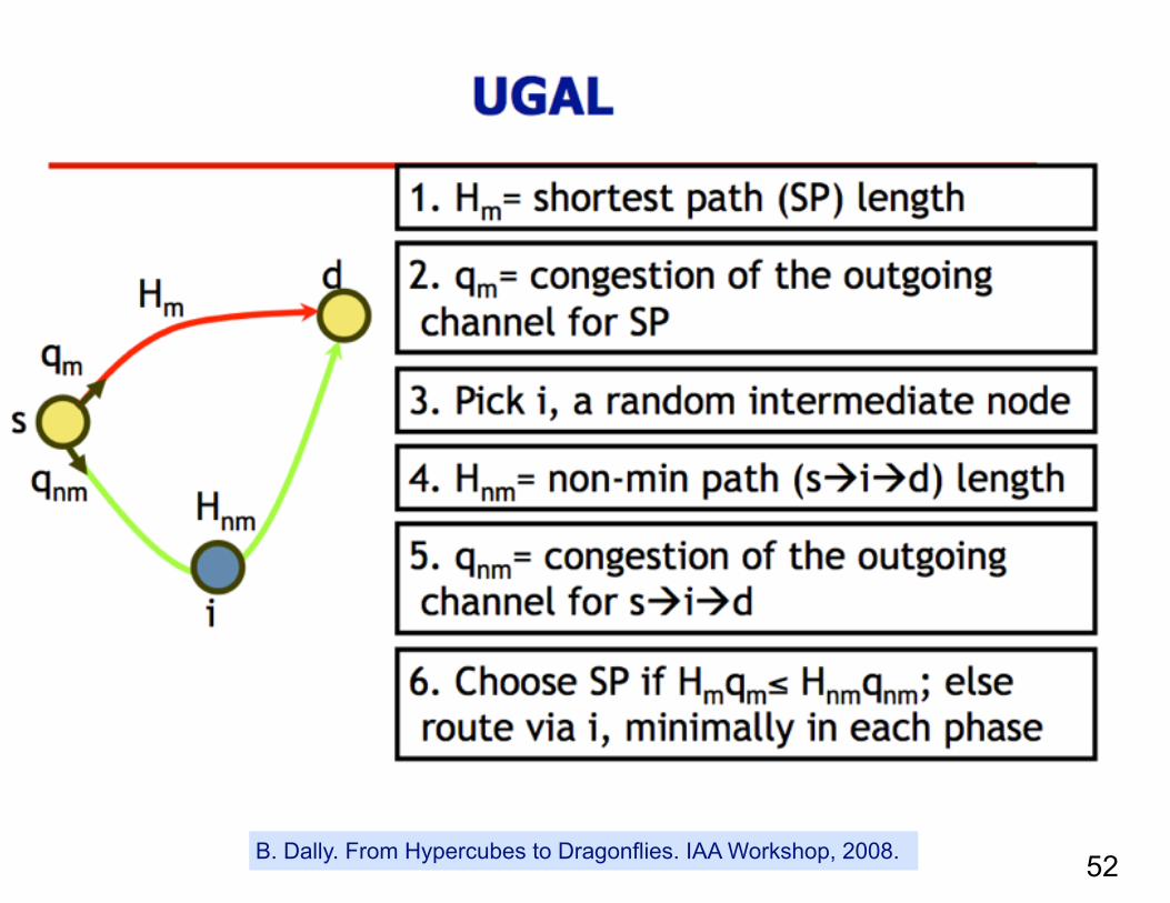
52B. Dally. From Hypercubes to Dragonflies. IAA Workshop, 2008.
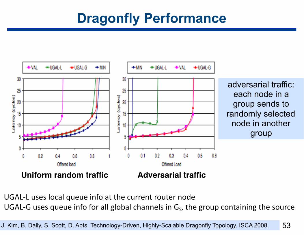
Dragonfly Performance
53
UGAL-LuseslocalqueueinfoatthecurrentrouternodeUGAL-GusesqueueinfoforallglobalchannelsinGs,thegroupcontainingthesource
J. Kim, B. Dally, S. Scott, D. Abts. Technology-Driven, Highly-Scalable Dragonfly Topology. ISCA 2008.
adversarial traffic: each node in a group sends to
randomly selected node in another
group
Uniform random traffic Adversarial traffic
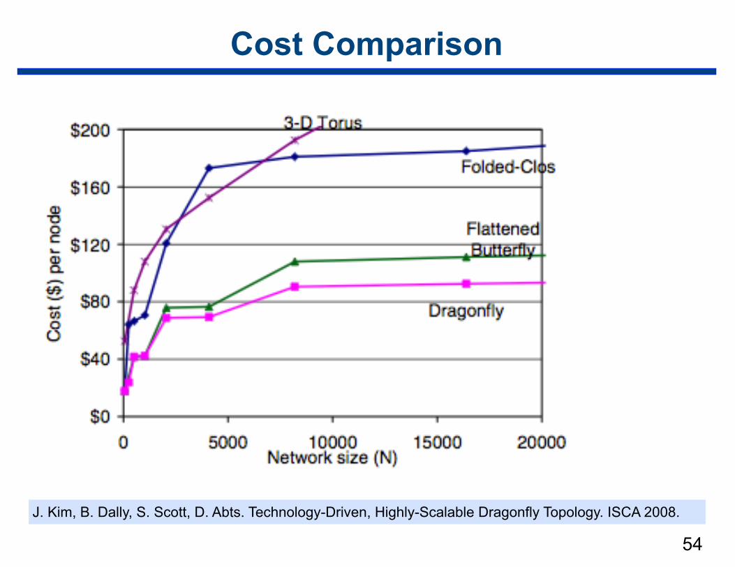
Cost Comparison
54
J. Kim, B. Dally, S. Scott, D. Abts. Technology-Driven, Highly-Scalable Dragonfly Topology. ISCA 2008.
55
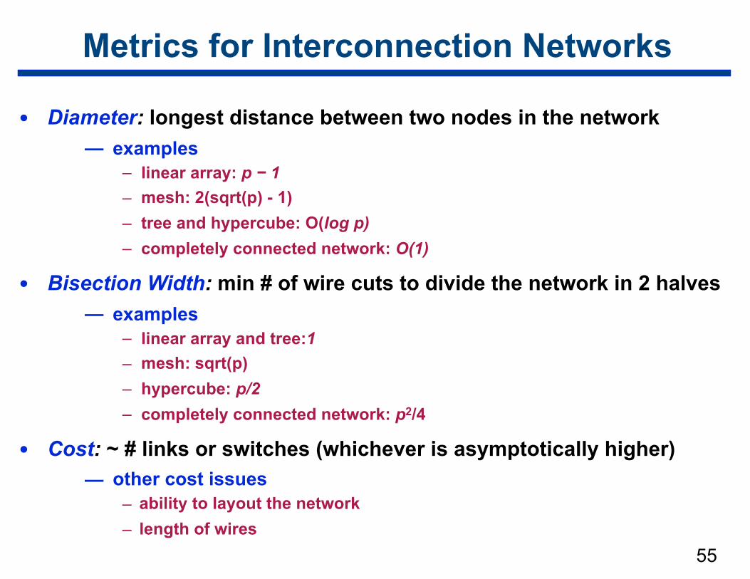
Metrics for Interconnection Networks
• Diameter: longest distance between two nodes in the network — examples
– linear array: p − 1 – mesh: 2(sqrt(p) - 1) – tree and hypercube: O(log p) – completely connected network: O(1)
• Bisection Width: min # of wire cuts to divide the network in 2 halves — examples
– linear array and tree:1 – mesh: sqrt(p) – hypercube: p/2 – completely connected network: p2/4
• Cost: ~ # links or switches (whichever is asymptotically higher) — other cost issues
– ability to layout the network – length of wires
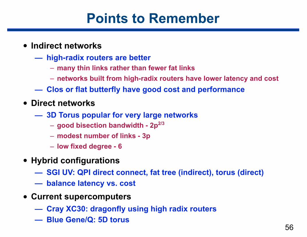
Points to Remember
• Indirect networks — high-radix routers are better
– many thin links rather than fewer fat links – networks built from high-radix routers have lower latency and cost
— Clos or flat butterfly have good cost and performance
• Direct networks — 3D Torus popular for very large networks
– good bisection bandwidth - 2p2/3 – modest number of links - 3p – low fixed degree - 6
• Hybrid configurations — SGI UV: QPI direct connect, fat tree (indirect), torus (direct) — balance latency vs. cost
• Current supercomputers — Cray XC30: dragonfly using high radix routers — Blue Gene/Q: 5D torus
56
57
References
• Adapted from slides “Parallel Programming Platforms” by Ananth Grama
• Based on Chapter 2 of “Introduction to Parallel Computing” by Ananth Grama, Anshul Gupta, George Karypis, and Vipin Kumar. Addison Wesley, 2003
• John Kim, William J. Dally, Dennis Abts: Flattened butterfly: a cost-efficient topology for high-radix networks. ISCA 2007: 126-137.
• Lawrence C. Stewart and David Gingold. A New Generation of Cluster Interconnect . SiCortex White Paper. December 2006/revised April 2008.
• Technical Advances in the SGI® Altix® UV Architecture. http://www.sgi.com/pdfs/4192.pdf