Embed Size (px)
Citation preview
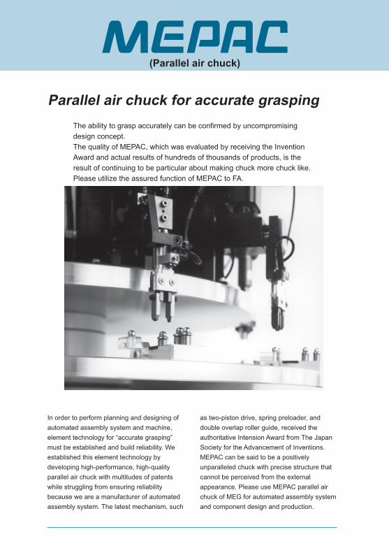
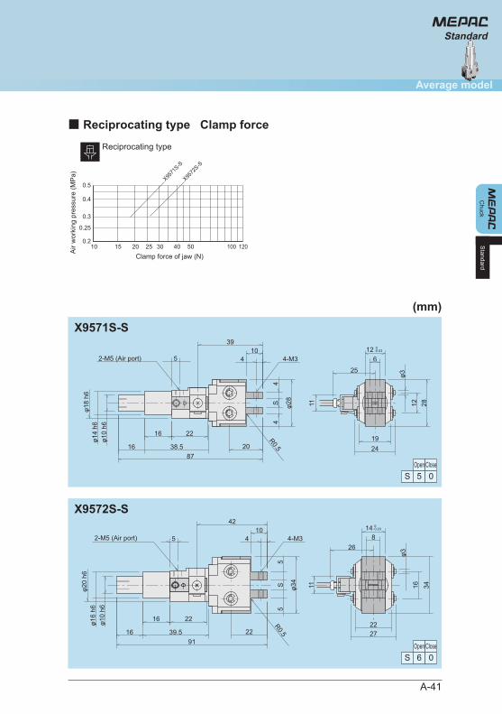
In order to perform planning and designing of automated assembly system and machine, element technology for “accurate grasping” must be established and build reliability. We established this element technology by developing high-performance, high-quality parallel air chuck with multitudes of patents while struggling from ensuring reliability because we are a manufacturer of automated assembly system. The latest mechanism, such
as two-piston drive, spring preloader, and double overlap roller guide, received the authoritative Intension Award from The Japan Society for the Advancement of Inventions. MEPAC can be said to be a positively unparalleled chuck with precise structure that cannot be perceived from the external appearance. Please use MEPAC parallel air chuck of MEG for automated assembly system and component design and production.
The ability to grasp accurately can be confirmed by uncompromising design concept. The quality of MEPAC, which was evaluated by receiving the Invention Award and actual results of hundreds of thousands of products, is the result of continuing to be particular about making chuck more chuck like. Please utilize the assured function of MEPAC to FA.
Parallel air chuck for accurate grasping
(Parallel air chuck)
A-1
ChuckMEG parallel air chuck
PageIndex
A-2Model selection
A-30
A-42
A-46
A-52
Standard
Taste
All-purpose
Smart
A-6
A-14
A-24
Eco
ECO-Multi
Motorized (Unclamp)
A-56
A-60
A-66
Micro
Short
Floating
A-72
A-76
A-80
A-82
A-84
A-86
A-88
A-90
A-95
A-96
A-98
Design precautions
Mounting precautions
Piping precautions
Handling precautions
Sensor band for sensor VR15
Applications
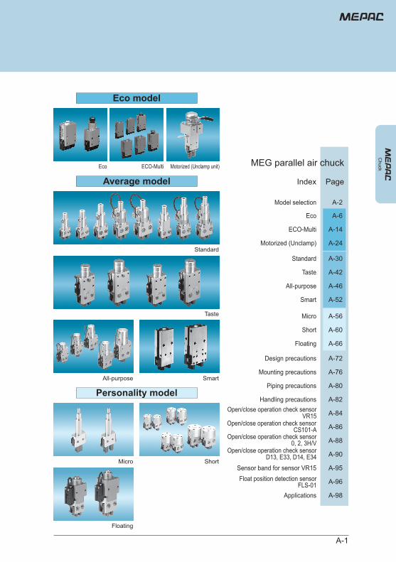
Micro
Floating
Short
Eco model
Personality model
Standard
Taste
All-purpose
Average modelECO-MultiEco Motorized (Unclamp unit)
Smart
Open/close operation check sensorD13, E33, D14, E34
Open/close operation check sensor0, 2, 3H/V
Open/close operation check sensorCS101-A
Open/close operation check sensorVR15
Float position detection sensorFLS-01
Perso
nality
mode
l
A-2
(Parallel air chuck)
Model selection
Chu
ck
Sing
le ac
tion
Smart
All-purpose
Standard
Taste
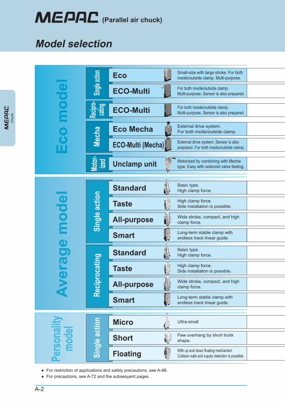
Basic type. High clamp force.
High clamp force. Side installation is possible.
Long-term stable clamp with endless track linear guide.
Wide stroke, compact, and high clamp force.
Recip
roca
ting
Smart
All-purpose
Standard
Taste
Basic type. High clamp force.
High clamp force. Side installation is possible.
Long-term stable clamp with endless track linear guide.
Wide stroke, compact, and high clamp force.Av
erag
e m
odel
Sing
le ac
tion Micro Ultra-small
Short Few overhang by short trunk shape.
Floating With up and down floating mechanism. Collision safe and supply detection is possible.
Eco
mod
el Single
action
Mech
a
ECO-Multi (Mecha) External drive system. Sensor is also prepared. For both inside/outside clamp.
Recipro
-cat
ing ECO-Multi For both inside/outside clamp. Multi-purpose. Sensor is also prepared.
ECO-Multi For both inside/outside clamp. Multi-purpose. Sensor is also prepared.
Eco Small-size with large stroke. For both inside/outside clamp. Multi-purpose.
Motor
-ize
d Unclamp unit Motorized by combining with Mecha type. Easy with solenoid valve feeling.
Eco Mecha External drive system. For both inside/outside clamp.
●●
For restriction of applications and safety precautions, see A-98. For precautions, see A-72 and the subsequent pages.
A-3
Model selection
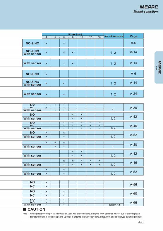
Stroke (mm)No. of sensors Page4 5 6 8 10 12 16
With sensor××
×× 1, 2 A-42
With sensor××
××
××
××
×× 1, 2 A-46
With sensor××
×× 1, 2 A-52
NONC
×× A-56
NONC
××
×× A-60
× × A-14
NO & NC
With sensorNO & NC
× × A-6
NO & NC ×
×
A-6
With sensor × ×
×
× A-14
1, 2
1, 2
With sensor × × A-241, 2
1, 2 A-14
With sensor × ×××
× ×
Each x1A-66
NONC
NOWith sensor × ×
×××× ×
1A-30
With sensor××
×× 1, 2 A-42
With sensor××
××× 1 A-30
NOWith sensor
××
×× 1, 2 A-52
NONC
With sensor ××× ×
××
××× ×
×
××××
1, 2A-46
NONC
Chuck
With sensorNO & NC
Note 1. Although reciprocating of standard can be used with the open hand, clamping force becomes weaker due to the thin piston diameter in order to increase opening velocity. In order to use with open hand, select from all-purpose type as far as possible.
■ CAUTION
×
A-4
X9558
X9559
X9560
X9561
X9562
X9563T
X9564T
X9558B
X9559B
X9560B
X9562B
X9560FL
X9562FL
X9670
X9672
X9660
X9661
X9662
X9663
X9664
X9600
X9605
4
4
4
5
6
8
10
4
4
4
6
4
6
4
6
6
8
10
12
16
4
4
5.0
8.5 10.0
13.0 13.5
18.0
24.0 27.0
38.0
68.0
5.0 4.5
8.5 10.0
13.0 13.5
24.0 27.0
13.0 13.5
24.0 27.0
16.0
31.0
10.5 18.0
18.0 24.0
26.0 32.0
40.0 50.0
70.0 80.0
3.0
3.0
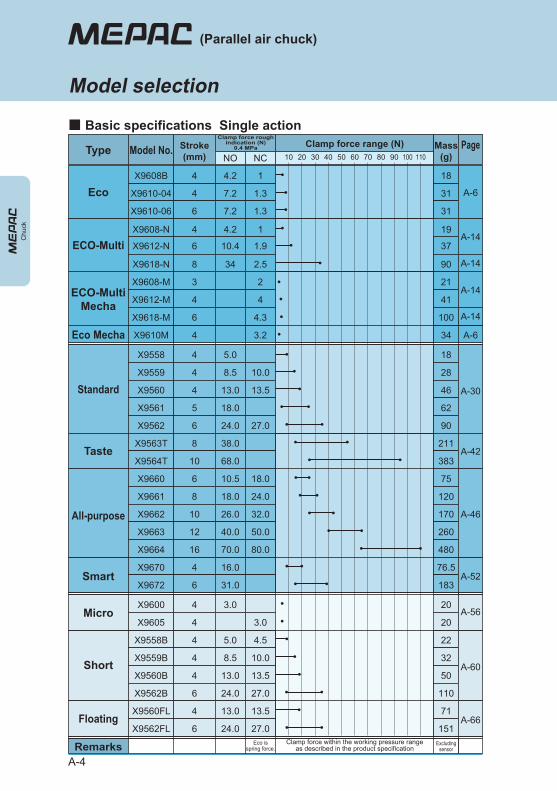
Clamp force within the working pressure rangeas described in the product specification
Excludingsensor
Eco isspring force.
NO NC 10 20 30 40 50 60 70 80 90 100 110
18
28
46
62
90
211
383
22
32
50
110
71
151
76.5
183
75
120
170
260
480
20
20
(Parallel air chuck)
Model selection
■ Basic specifications Single action
Type
Standard
Taste
Short
Floating
Smart
All-purpose
Micro
Remarks
Clamp force roughindication (N)
0.4 MPa Clamp force range (N)Model No. Stroke(mm)
Mass(g)
A-30
A-42
A-60
A-66
A-52
A-46
A-56
Page
X9608-M
X9612-M
3
4ECO-Multi
Mecha
X9610-04
X9610-06
4
6
7.2
7.2
1.3
1.3
31
X9608B 4 4.2 1 18
31
Eco A-6
ECO-MultiX9608-N 4 4.2 1 19
X9618-N 8 34 2.5 90
X9612-N 6 10.4 1.9 37A-14
21
41A-14
X9610M 4 34Eco Mecha A-6
A-14
A-14
2
4
X9618-M 6 1004.3
3.2
Chu
ck
A-5
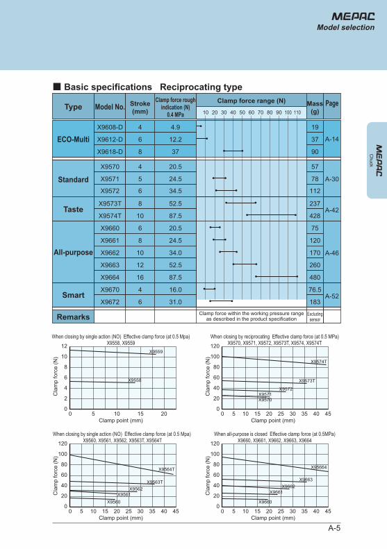
X9570
X9571
X9572
X9573T
X9574T
X9670
X9672
X9660
X9661
X9662
X9663
X9664
4
5
6
8
10
4
6
6
8
10
12
16
20.5
24.5
34.5
52.5
87.5
16.0
31.0
20.5
24.5
34.0
52.5
87.5
Clamp force within the working pressure rangeas described in the product specification
Excludingsensor
10 20 30 40 50 60 70 80 90 100 110
57
78
112
237
428
76.5
183
75
120
170
260
480
Model selection
Type
Standard
Taste
Smart
All-purpose
Remarks
Clamp force roughindication (N)
0.4 MPa
Clamp force range (N)Model No. Stroke
(mm)Mass
(g)
■ Basic specifications Reciprocating type
A-42
A-52
A-46
A-30
Page
Chuck
X9608-D
X9612-D
4
6
4.9
12.2ECO-Multi19
37
X9618-D 8 37 90
A-14
2
00
4
6
8
10
12
5 10 15 20
Cla
mp
forc
e (N
)
When closing by single action (NO) Effective clamp force (at 0.5 Mpa)X9558, X9559
Clamp point (mm)
20
050
40
60
80
100
120
10 15 20 25 30 35 40 45
Cla
mp
forc
e (N
)
When closing by reciprocating Effective clamp force (at 0.5 MPa)X9570, X9571, X9572, X9573T, X9574, X9574T
Clamp point (mm)
X9559
X9558
X9570X9571
X9572
X9573T
X9574T
When all-purpose is closed Effective clamp force (at 0.5MPa)X9660, X9661, X9662, X9663, X9664
20
050
40
60
80
100
120
10 15 20 25 30 35 40 45
Cla
mp
forc
e (N
)
When closing by single action (NO) Effective clamp force (at 0.5 Mpa) X9560, X9561, X9562, X9563T, X9564T
Clamp point (mm)
X9560X9561
X9562X9563T
X9564T
20
050
40
60
80
100
120
10 15 20 25 30 35 40 45
Cla
mp
forc
e (N
)
Clamp point (mm)
X9660
X9661X9662
X9663
X95664
A-6
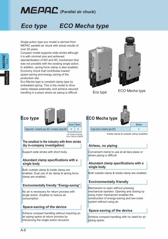
Single-action type eco model is derived from MEPAC parallel air chuck with actual results of over 20 years. Compact model supports wide stroke although it is with minimal size and achieved standardization of NO and NC mechanism that was not possible with the existing single action. In addition, spring force clamp is also enabled. Economy chuck that contributes toward space-saving and energy saving of the production site. Eco Mecha type is constant clamp type by embedded spring. This is the model to drive clamp release externally, and achieve assured handling in a place where air piping is difficult.
Chu
ckEc
o/Ec
o M
echa
(Parallel air chuck)
Eco type ECO Mecha type
Eco type ECO Mecha type
Support wide stroke with short body.
The smallest in the industry with 6mm stroke (by in-company investigation)
Both outside clamp & inside clamp are enabled. Dual use of air clamp & spring force clamp are enabled.
Abundant clamp specifications with a single body
No air is necessary for return process with single action. Enables to reduce air consumption.
Environmentally friendly “Energy-saving”
Achieve compact handling without requiring an air piping space at return process by introducing the single action structure.
Space-saving of the device
4mmSingle action Constantly open (NO), Constantly closed (NC) ×
6mm×
Convenient clamp to use at air-less place or where piping is difficult.
Airless, no piping
Both outside clamp & inside clamp are enabled.
Abundant clamp specifications with a single body
Mechanism to open without pressing mechanical operator. Opening and closing by using motor mechanism enables the construction of energy-saving and low-noise system without using air.
Environmentally friendly
Achieve compact handling with no need for air piping space.
Space-saving of the device
Single action Constantly open (NO)Inside clamp & outside clamp enabled
4mm×
Eco type ECO Mecha type
Air clamp & spring force clamp enabled

A-7
Chuck
Eco model
Eco/Eco Mecha
Eco/Eco Mecha
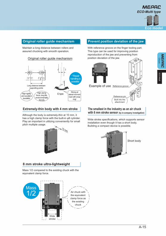
Maintain a long distance between rollers and assured chucking with smooth operation.
Original roller guide mechanismWith reference groove on the finger tooling part. This type can be used for improving position reproduction of the jaw and preventing from position deviation of the jaw.
Prevent position deviation of the jaw
Example of useReferencegroove
Reference pin
Original roller guide mechanism
ECO-Multi existing product E type
Long distance betweensupporting points
With E type snap ring
* Repair handling is possible.
High clampforce, long life,environmentally
friendly
Eco type■ Clamp specifications
■ Open/Close motions
Outside clamp Inside clamp
Air IN
Air clamp
Air OUT
Spring clamp Air clamp Spring clamp
Air IN Air OUT
ECO Mecha type
When the mechanical operator is pressed externally, the piston is slided and the drive roller pushes the finger tooling to release the clamp.
Pus
h
Piston
Mechanical operator
Finger tooling
Drive roller
Outside clamp Inside clamp
Spring clamp Spring clamp
High rigidity and excellent
durability!
Strong at horizontal moment load!
Built into the attachment
With snap ring
X9610E (E type)
A-8
●
●
●
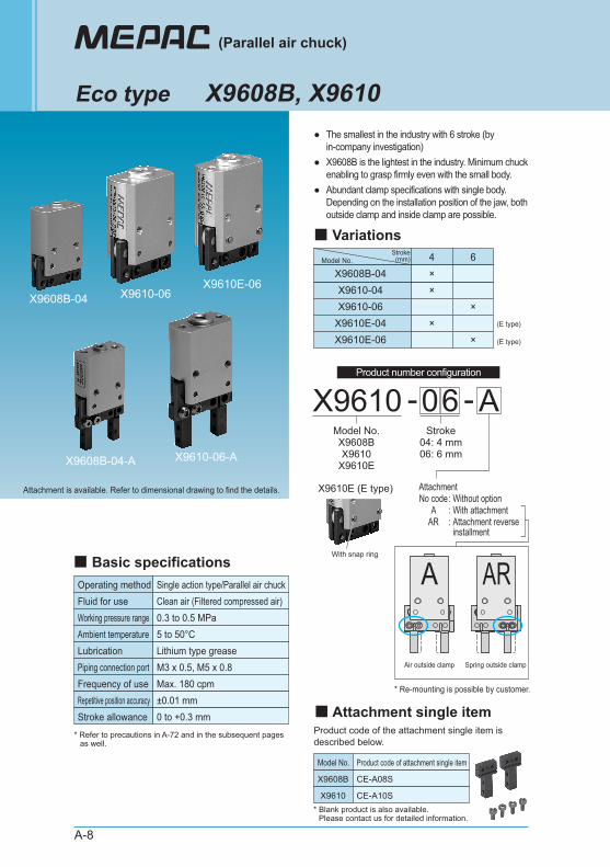
The smallest in the industry with 6 stroke (by in-company investigation) X9608B is the lightest in the industry. Minimum chuck enabling to grasp firmly even with the small body. Abundant clamp specifications with single body. Depending on the installation position of the jaw, both outside clamp and inside clamp are possible.
(Parallel air chuck)
Eco type X9608B, X9610
4 6
X9610-04 ×X9608B-04 ×
X9610-06 ×X9610E-04 ×X9610E-06 ×
Model No.
(E type)
(E type)
Stroke(mm)
■ Variations
X9610 06-Model No.X9608BX9610
X9610E
Stroke04: 4 mm06: 6 mm
■ Basic specificationsOperating method Single action type/Parallel air chuck
Model No. Product code of attachment single item
X9608B CE-A08S
X9610 CE-A10S
Clean air (Filtered compressed air)0.3 to 0.5 MPa
Max. 180 cpm±0.01 mm
Fluid for useWorking pressure range
5 to 50°CAmbient temperatureLithium type greaseLubrication
Frequency of useM3 x 0.5, M5 x 0.8Piping connection port
Repetitive position accuracy0 to +0.3 mmStroke allowance
A-
Attachment No code : Without option A : With attachment AR : Attachment reverse
installment
Attachment is available. Refer to dimensional drawing to find the details.
* Refer to precautions in A-72 and in the subsequent pages as well.
X9610-06
X9610-06-A
X9608B-04
X9608B-04-A
X9610E-06
Air outside clamp Spring outside clamp
* Re-mounting is possible by customer.
ARA
■ Attachment single itemProduct code of the attachment single item is described below.
* Blank product is also available. Please contact us for detailed information.
Product number configuration
A-9
Chuck
Eco model
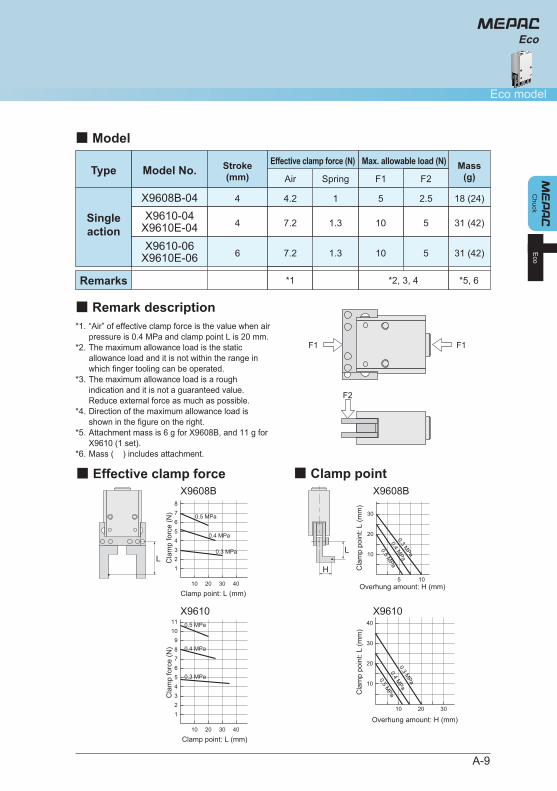
■ Remark description
■ Model
X9608B-04X9610-04
X9610E-04
4
4
5
10
2.5
5
18 (24)
31 (42)
F1 F2
*2, 3, 4 *5, 6
1
1.3
SpringType
Singleaction
Remarks
Model No.Max. allowable load (N)
4.2
7.2
X9610-06X9610E-06 6 10 5 31 (42)1.37.2
Air
*1
Effective clamp force (N)Stroke(mm)
Mass(g)
*1.
*2.
*3.
*4.
*5.
*6.
“Air” of effective clamp force is the value when air pressure is 0.4 MPa and clamp point L is 20 mm. The maximum allowance load is the static allowance load and it is not within the range in which finger tooling can be operated. The maximum allowance load is a rough indication and it is not a guaranteed value. Reduce external force as much as possible. Direction of the maximum allowance load is shown in the figure on the right. Attachment mass is 6 g for X9608B, and 11 g for X9610 (1 set). Mass ( ) includes attachment.
F2
F1 F1
Eco
Eco
■ Effective clamp force ■ Clamp point
LH
L
Cla
mp
forc
e (N
)
Clamp point: L (mm)
123456789
1011
20 4010 30
0.3 MPa
0.4 MPa
0.5 MPa
Cla
mp
forc
e (N
)
Clamp point: L (mm)
12345678
20 4010 30
0.3 MPa
0.4 MPa
0.5 MPa
Cla
mp
poin
t: L
(mm
)
Overhung amount: H (mm)
10
20
30
40
10 20 30
0.3 MPa
0.4 MPa
0.5 MPa
Cla
mp
poin
t: L
(mm
)
Overhung amount: H (mm)
10
20
30
5 10
0.3 MPa
0.4 MPa
0.5 MPa
X9608B X9608B
X9610 X9610

A-10
Chu
ck
(Parallel air chuck)
Eco type
Eco
X9608B-04
X9608B-04-A
■ Dimensional drawing (mm)
Jaw mounting
(Air port)
12
2.5
5±0
.1
95±0
.1
2.5
24±0
.1
2.513
15.5
32 1.533.5
2-M3 (Through)
R0.3 or less
φ22
5.51.5
3.1
0 -0.1
1.5
4
13.6
1313
26
C0.2
φ6h7
0 -0.0
12
3.6
1.2+0
.02
0
142 x 4-φ2.2
2-M3 Depth 6
M3
10 0 -0
.05
4
(16
to) 2
0
11
4
2.5 5
22
4 0 -0.0
5
2 x 2-M2 12
*
*
*
The figure indicates the state when the air is out. Two finger toolings are the same parts. The finger tooling moves 2 mm each towards the arrow direction by the air through the port.
* The attachment installation direction of X9608B-04-AR becomes opposite to what is shown in the figure.
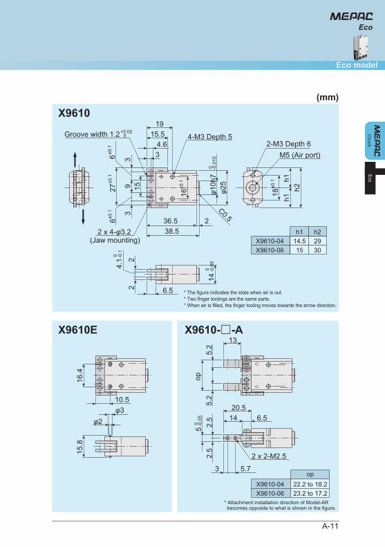
X9610
A-11
Chuck
Eco model
* The figure indicates the state when air is out. * Two finger toolings are the same parts. * When air is filled, the finger tooling moves towards the arrow direction.
X9610E X9610-□-A
Eco
Eco
(Jaw mounting)
14
18±0
.1
h1h1
h2
2-M3 Depth 6
36.5 238.5
3
6±0.1
9 15
6±0.1
3
27±0
.1
φ10h
7 0 -0
.015
0 -0.0
5
0 -0.1
φ25
C0.5
4-M3 Depth 5
16±0
.1
6.52
4.1 2
M5 (Air port)
Groove width 1.2 15.519
4.63
+0.02 0
2 x 4-φ3.2
5.2
5.2
op
13
2.5
2.5
5 0 -0
.05 14 6.5
20.5
3 5.7
2 x 2-M2.5
φ2φ3
15.8
16.4
10.5
X9610-04 14.5 29h1 h2
X9610-06 15 30
X9610-04 22.2 to 18.2op
X9610-06 23.2 to 17.2* Attachment installation direction of Model-AR becomes opposite to what is shown in the figure.
(mm)
A-12
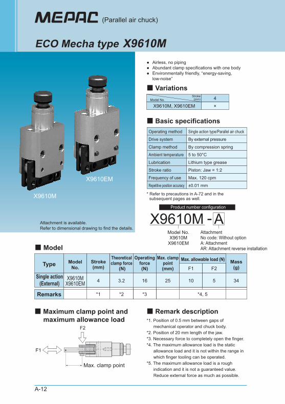
●●●
Airless, no piping Abundant clamp specifications with one bodyEnvironmentally friendly, “energy-saving, low-noise”
(Parallel air chuck)
ECO Mecha type
Attachment is available.Refer to dimensional drawing to find the details.
X9610M
4X9610M, X9610EM ×
Model No.Stroke
(mm)
■ Variations
X9610MModel No.X9610M
X9610EM
■ Basic specificationsOperating method Single action type/Parallel air chuck
By external pressure
By compression spring
Max. 120 cpm
±0.01 mm
Drive system
Clamp method
5 to 50°CAmbient temperature
Lithium type greaseLubrication
Frequency of use
Piston: Jaw = 1:2Stroke ratio
Repetitive position accuracy
■ ModelMax. allowable load (N)
X9610MX9610EM 4 10 5 34
F1 F2
*4, 5
Type
Max. clamp point
Single action(External)
Remarks
ModelNo.
*1 *2 *3
Stroke(mm)
3.2
Theoreticalclamp force
(N)
16
Operatingforce(N)
25
Max. clamppoint(mm)
Mass(g)
* Refer to precautions in A-72 and in the subsequent pages as well.
■ Remark description■ Maximum clamp point and maximum allowance load *1. Position of 0.5 mm between gaps of
mechanical operator and chuck body. *2. Position of 20 mm length of the jaw. *3. Necessary force to completely open the finger. *4. The maximum allowance load is the static
allowance load and it is not within the range in which finger tooling can be operated.
*5. The maximum allowance load is a rough indication and it is not a guaranteed value. Reduce external force as much as possible.
F1
F2
A-AttachmentNo code: Without optionA: AttachmentAR: Attachment reverse installation
X9610M
X9610EM
Product number configuration
X9610M
X9610EM X9610M-A
A-13
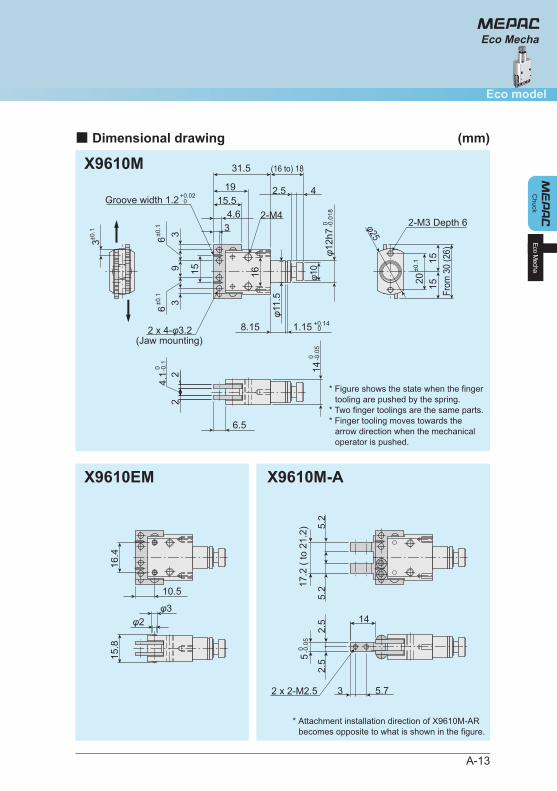
■ Dimensional drawing (mm)
Chuck
Eco model
Eco Mecha
Eco Mecha
(Jaw mounting)
16 φ10
φ25
φ12h
7 0 -0
.018
1515 From
30
(26)
6.5
31.5 (16 to) 18
8.15 1.15 +0.14 0
φ11.
5
2.5 4
3±0.1
36±0
.1
9 15
6±0.1
32
4.1 2
Groove width 1.2 +0.02 0 15.5
19
4.63
2 x 4-φ3.2
2-M42-M3 Depth 6
20±0
.1
14 0 -0
.05
0 -0.1
φ2φ3
15.8
16.4
10.5
5.2
5.2
2.5
2.5
3 5.7
14
2 x 2-M2.5
5 0 -0
.05
17.2
( to
21.
2)
* Attachment installation direction of X9610M-AR becomes opposite to what is shown in the figure.
* Figure shows the state when the finger tooling are pushed by the spring.
* Two finger toolings are the same parts. * Finger tooling moves towards the
arrow direction when the mechanical operator is pushed.
4 mm stroke 6 mm stroke 8 mm stroke
A-14
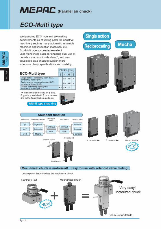
We launched ECO type and are making achievements as chucking parts for industrial machinery such as many automatic assembly machines and inspection machines, etc. Eco-Multi type succeeded excellent user-friendliness such as “enabling dual use of outside clamp and inside clamp”, and was developed as a chuck to support more extensive clamp specifications and usability.
Chu
ckEC
O-M
ulti
(Parallel air chuck)
ECO-Multi type
Stroke (mm)
Single action constantly open (NO), constantly closed (NC)
ECO-Multi type
Unclamp unit Mechanical chuck
Very easy! Motorized chuck
××Reciprocating constantly open (NO), constantly closed (NC) ××Mecha constantly open (NO), constantly closed (NC) ×× ×× ×
××3 4 6
×××8
×
With E type snap ring
Single action
Reciprocating Mecha
Main body Center portoptionOperating method
Unclamp unit that motorizes the mechanical chuck.
See A-24 for details.
Sensor optionCenter port
Attachment
Attachment
Single actionWithout
φ8
φ12
φ18With
Reciprocating
Mecha
Abundant function
Mechanical chuck is motorized! Easy to use with solenoid valve feeling.
Sensor option
Without
With
Without
1 sensor
2 sensors
NEW
NEWVariation
×× indicates that there is an E type.E type is a model with E type retainer ring to the finger tooling guide pin.
A-15
Chuck
Eco model
ECO-M
ulti
ECO-Multi type
Although the body is extremely-thin at 10 mm, it has a high clamp force with the built-in φ8 cylinder. Play an important in utilizing conveniently for small pitch multiple usage.
Extremely-thin body with 4 mm stroke
Wide stroke specifications, which supports sensor installation even though it has a short body. Building a compact device is possible.
The smallest in the industry as an air chuckwith 6 mm stroke sensor (by in-company investigation)
10 mm
Short body
With reference groove on the finger tooling part. This type can be used for improving position reproduction of the jaw and preventing from position deviation of the jaw.
Prevent position deviation of the jaw
Example of use Reference groove
Reference pin
Maintain a long distance between rollers and assured chucking with smooth operation.
Original roller guide mechanism
Original roller guide mechanism
Long distance betweensupporting points
High clampforce, long life,
environmentallyfriendly
E type
Mass 1/2 compared to the existing chuck with the equivalent clamp force.
8 mm stroke ultra-lightweight
Mass1/2
NEWVariation
NEWVariation
High rigidity and excellent
durability!
Strong at lateral moment load with snap
ring!
* Repair handling is possible.
Built into the attachment
Air chuck with the equivalent clamp force as
the existing chuck
Wide stroke
A-16
Chu
ckEC
O-M
ulti
(Parallel air chuck)
ECO-Multi type
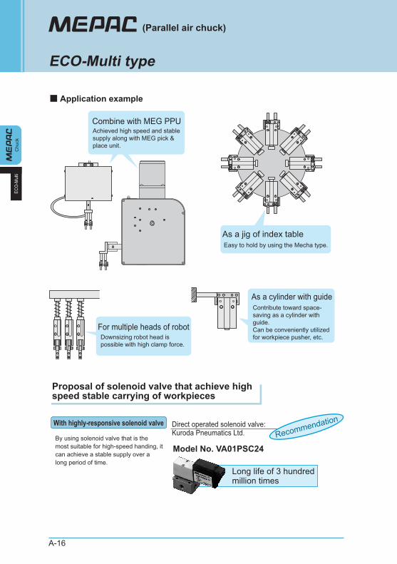
Proposal of solenoid valve that achieve high speed stable carrying of workpieces
■ Application example
As a jig of index tableEasy to hold by using the Mecha type.
As a cylinder with guide
For multiple heads of robot
Combine with MEG PPU
By using solenoid valve that is the most suitable for high-speed handing, it can achieve a stable supply over a long period of time.
With highly-responsive solenoid valve
Long life of 3 hundred million times
Direct operated solenoid valve: Kuroda Pneumatics Ltd.
Model No. VA01PSC24Recommendation
Achieved high speed and stable supply along with MEG pick & place unit.
Downsizing robot head is possible with high clamp force.
Contribute toward space- saving as a cylinder with guide. Can be conveniently utilized for workpiece pusher, etc.
A-17
Chuck
Eco model
ECO-M
ulti
ECO-Multi type
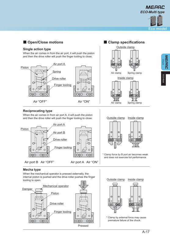
Single action type
Air port B Air “OFF” Air port A Air “ON”
Pressed
■ Open/Close motions ■ Clamp specifications
When the air comes in from the air port, it will push the piston and then the drive roller will push the finger tooling to close.
Reciprocating typeWhen the air comes in from air port A, it will push the piston and then the drive roller will push the finger tooling to close.
Mecha typeWhen the mechanical operator is pressed externally, the internal piston is pushed and the drive roller pushes the finger tooling to open.
PistonAir port A
Air port B
Drive roller
Finger tooling
Mechanical operator
Piston
Drive roller
Finger tooling
Damper
Pus
h
Air clamp Spring clamp
Inside clamp
Air “OFF” Air “ON”
PistonAir port A
Spring
Drive roller
Finger tooling
Outside clamp
Air clamp Spring clamp
Outside clamp Inside clamp
Outside clamp Inside clamp
NEWVariation
* Clamp force by B port air becomes weak and does not exercise full performance.
* Clamp by external force may cause premature failure of the chuck.
With E type snap ring
A-18
●
●
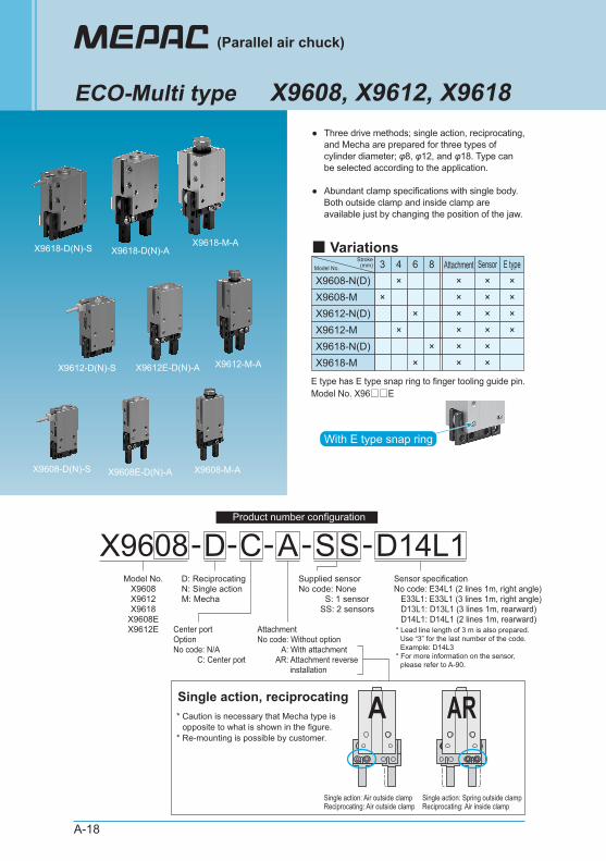
Three drive methods; single action, reciprocating, and Mecha are prepared for three types of cylinder diameter; φ8, φ12, and φ18. Type can be selected according to the application.
Abundant clamp specifications with single body. Both outside clamp and inside clamp are available just by changing the position of the jaw.
(Parallel air chuck)
ECO-Multi type X9608, X9612, X9618
3 SensorX9608-N(D)
4×
6
×X9608-M ×
Attachment
××X9612-N(D) ××
×X9612-M ××X9618-N(D) ××
×
8
×X9618-M ××
×E type
×××
××Model No.
Stroke(mm)
■ Variations
Center portOptionNo code: N/A C: Center port
AttachmentNo code: Without option A: With attachment AR: Attachment reverse installation
X9612-D(N)-S X9612-M-AX9612E-D(N)-A
X9618-D(N)-S X9618-M-AX9618-D(N)-A
X9608E-D(N)-AX9608-D(N)-S X9608-M-A
Single action: Air outside clampReciprocating: Air outside clamp
Single action: Spring outside clampReciprocating: Air inside clamp
* Lead line length of 3 m is also prepared. Use “3” for the last number of the code. Example: D14L3* For more information on the sensor, please refer to A-90.
E type has E type snap ring to finger tooling guide pin. Model No. X96□□E
X9608-Model No.
X9608X9612X9618
X9608EX9612E
D: ReciprocatingN: Single actionM: Mecha
Supplied sensorNo code: None S: 1 sensor SS: 2 sensors
D-C -S -D14L1S-ASensor specificationNo code: E34L1 (2 lines 1m, right angle) E33L1: E33L1 (3 lines 1m, right angle) D13L1: D13L1 (3 lines 1m, rearward) D14L1: D14L1 (2 lines 1m, rearward)
ARASingle action, reciprocating* Caution is necessary that Mecha type is
opposite to what is shown in the figure. * Re-mounting is possible by customer.
Product number configuration
A-19
Chuck
Eco model
■ Attachment single item
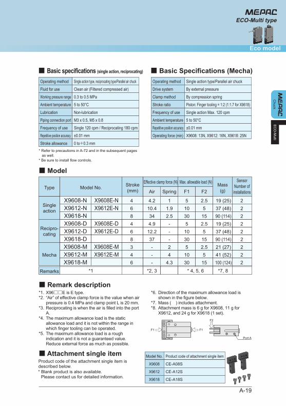
■ Model
X9608-NX9612-N
46
510
2.55
19 (25)37 (48)
F1 F2
* 4, 5, 6
11.9
SpringType
Singleaction
Remarks
Model No.Max. allowable load (N)
4.210.4
Air
*2, 3*1 *7, 8
Effective clamp force (N)Stroke(mm)
Mass(g)
22
X9618-N 8 30 15 90 (114)2.534 2
X9608-MX9612-M
34
510
2.55
21 (27)41 (52)
24Mecha
--
22
X9618-M 6 30 15 100 (124)4.3- 2
X9608-DX9612-D
46
510
2.55
19 (25)37 (48)
--
Recipro-cating
4.912.2
22
X9618-D
X9608E-NX9612E-N
X9608E-MX9612E-M
X9608E-DX9612E-D
8 30 15 90 (114)-37 2
SensorNumber of
installations
EC
O-M
ulti
ECO-Multi type
F2
F1 F1
Port A
Product code of the attachment single item is described below.
■ Remark description*1.*2.
*3.
*4.
*5.
X96□□E is E type. “Air” of effective clamp force is the value when air pressure is 0.4 MPa and clamp point L is 20 mm. Reciprocating is when the air is filled into the port A. The maximum allowance load is the static allowance load and it is not within the range in which finger tooling can be operated. The maximum allowance load is a rough indication and it is not a guaranteed value. Reduce external force as much as possible.
*6.
*7.*8.
Direction of the maximum allowance load is shown in the figure below. Mass ( ) includes attachment. Attachment mass is 6 g for X9608, 11 g for X9612, and 24 g for X9618 (1 set).
■ Basic specifications (single action, reciprocating)
Operating method Single action type, reciprocating type/Parallel air chuck
Clean air (Filtered compressed air)
0.3 to 0.5 MPa
Single 120 cpm / Reciprocating 180 cpm
±0.01 mm
Fluid for use
Working pressure range
5 to 50°CAmbient temperature
Non-lubricationLubrication
Frequency of use
M3 x 0.5, M5 x 0.8Piping connection port
Repetitive position accuracy
0 to+0.3 mmStroke allowance
■ Basic Specifications (Mecha)Operating method Single action type/Parallel air chuck
By external pressure
By compression spring
Single action Max. 120 cpm
±0.01 mm
Drive system
Clamp method
Piston: Finger tooling = 1:2 (1:1.7 for X9618) Stroke ratio
5 to 50°CAmbient temperature
Frequency of use
Repetitive position accuracy
X9608: 13N, X9612: 16N, X9618: 25NOperating force (min)
* Refer to precautions in A-72 and in the subsequent pages as well. * Be sure to install flow controls.
Model No. Product code of attachment single item
X9608 CE-A08S
X9612 CE-A12S
X9618 CE-A18S
* Blank product is also available. Please contact us for detailed information.

A-20
Chu
ckEC
O-M
ulti
(Parallel air chuck)
ECO-Multi type
■ Effective clamp force
■ Clamp point
H
L
Cla
mp
forc
e (N
)
Cla
mp
forc
e (N
)
Cla
mp
forc
e (N
)
Clamp point: L (mm) Clamp point: L (mm) Clamp point: L (mm)
X9608-N
2
4
6
8
20 4010 30
0.3 MPa
0.4 MPa
0.5 MPa
Cla
mp
forc
e (N
)
Cla
mp
forc
e (N
)
Cla
mp
forc
e (N
)Clamp point: L (mm) Clamp point: L (mm) Clamp point: L (mm)
* In case of spring force clamp, L dimension is X9608: 20mm, X9612: 30mm, X9618: 40mm (max)
X9608-D
X9608 X9612
2
4
6
8
20 4010 30
0.3 MPa
0.4 MPa
0.5 MPa
X9612-N
5
10
15
20
20 40 5010 30
0.3 MPa
0.4 MPa0.5 MPa
X9618-N
10
20
30
40
50
20 40 50 6010 30
0.3 MPa
0.4 MPa
0.5 MPa
X9612-D
5
10
15
20
20 40 5010 30
0.3 MPa
0.4 MPa
0.5 MPa
X9618-D
10
20
30
40
50
20 40 50 6010 30
0.3 MPa0.4 MPa
0.5 MPa
Cla
mp
poin
t: L
(mm
)
Overhung amount: H (mm)
10
20
30
5 10
0.3 MPa
0.4 MPa
0.5 MPa
Cla
mp
poin
t: L
(mm
)
Overhung amount: H (mm)
20
40
10
30
50
60
10 20
0.3 MPa
0.4 MPa
0.5 MPa
X9618
Cla
mp
poin
t: L
(mm
)
Overhung amount: H (mm)
20
40
10
30
50
60
10 20 30
0.3 MPa0.4 MPa
0.5 MPa
L
A-21
EC
O-M
ulti
ECO-Multi typeC
huck
Eco model
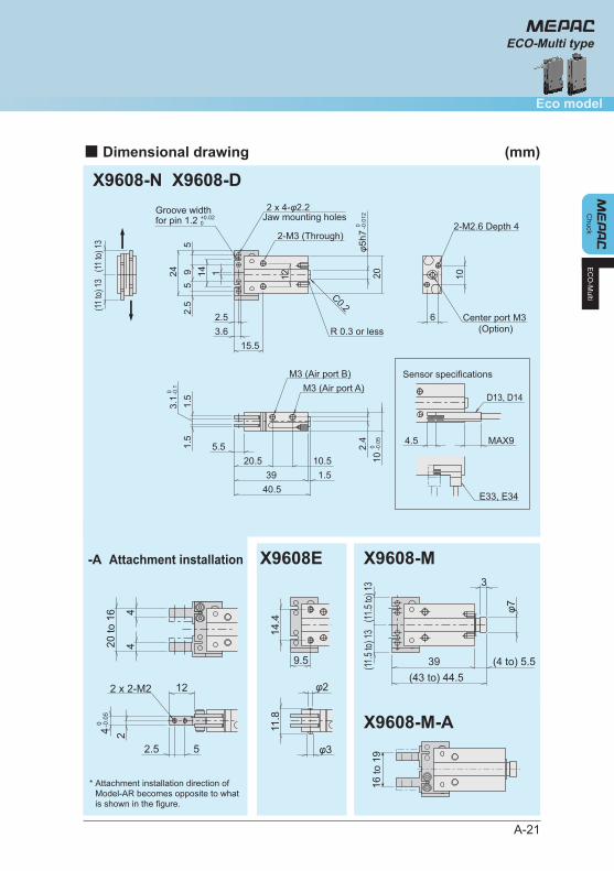
■ Dimensional drawing (mm)
X9608-N X9608-D
X9608-M
X9608-M-A
X9608E-A Attachment installation
Sensor specifications
Jaw mounting holes
(Option)
(11 to
) 13
(11 to
) 13
1142.
55
95
24
2.53.6
12
φ5h7
20
C0.2
R 0.3 or less6
10
2-M2.6 Depth 4
Groove width for pin 1.2
2 x 4-φ2.2
2-M3 (Through)
1.5
3.1
1.5
5.520.5 10.5
39 1.540.5
2.4
10M3 (Air port A)
M3 (Air port B)
15.5
MAX94.5
D13, D14
E33, E34
0 -0.1
0 -0.0
5
Center port M3
0 -0.0
12+0.020
39 (4 to) 5.5(43 to) 44.5
φ7
3
44
20 to
16
2.5 5
12
9.5
24 0 -0.0
5
2 x 2-M2
14.4
11.8
φ2
φ3
(11.5
to) 13
(11.5
to) 13
16 to
19
* Attachment installation direction of Model-AR becomes opposite to what is shown in the figure.
A-22
Chu
ck
(Parallel air chuck)
ECO-Multi type
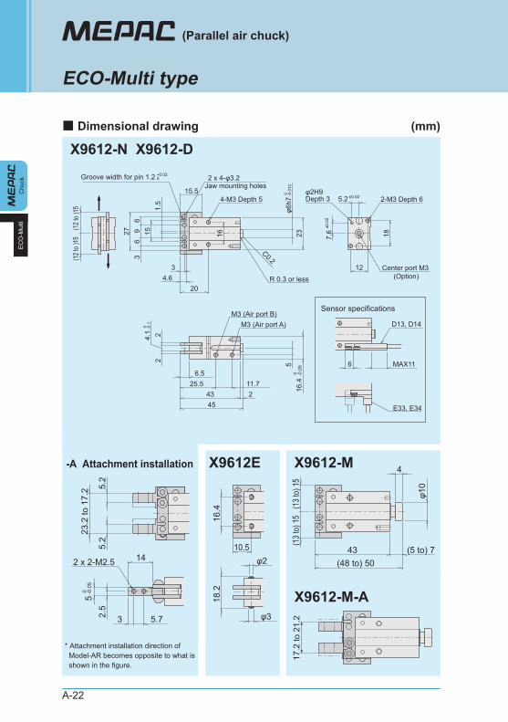
■ Dimensional drawing (mm)
EC
O-M
ulti
X9612-N X9612-D
X9612-M
X9612-M-A
X9612E-A Attachment installation
Sensor specifications
Jaw mounting holes
(Option)
1.5
153
69
627
4-M3 Depth 5
2 x 4-φ3.2
C0.2
23
R 0.3 or lessφ6
h7
34.6
20
15.5
16
2-M3 Depth 65.2
7.6
12
18
φ2H9Depth 3
(12
to )1
5(1
2 to
)15
Groove width for pin 1.2 +0.020
0 -0.0
12
0 -0.1
±0.0
2
±0.02
6.525.5 11.7
43 245
24.
1 2
M3 (Air port A)M3 (Air port B)
516
.4
6 MAX11
D13, D14
E33, E34
Center port M3
0 -0.0
5
5.2
5.2
23.2
to 1
7.2
2.5
5
1410.5
3 5.7
2 x 2-M2.543 (5 to) 7
(48 to) 50
φ10
4
16.4
φ2
φ3
18.2
(13
to) 1
5(1
3 to
) 15
* Attachment installation direction of Model-AR becomes opposite to what is shown in the figure.
0 -0.0
517
.2 to
21.
2
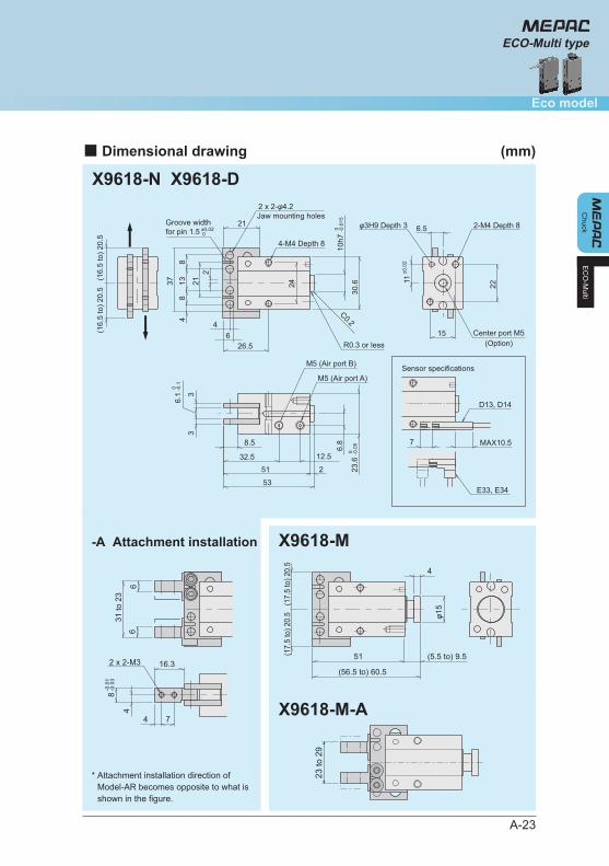
X9618-N X9618-D
X9618-M
X9618-M-A
-A Attachment installation
A-23
EC
O-M
ulti
ECO-Multi typeC
huck
Eco model
■ Dimensional drawing (mm)
Jaw mounting holes
(Option)
Sensor specifications
37
221
48
138
30.6
46
26.5
21
4-M4 Depth 8
2 x 2-φ4.2
10h7
C0.2
R0.3 or less
Groove widthfor pin 1.5 0 -0
.015
0 -0.1
0 -0.0
5
±0.0
2
22
15
11
6.5±0.02 0
(16.
5 to
) 20.
5(1
6.5
to) 2
0.5
32.5 12.5
6.8
23.6
2-M4 Depth 8φ3H9 Depth 3
Center port M5
24
51 2
53
3
6.1 3
MAX10.5
D13, D14
E33, E34
7
M5 (Air port A)
M5 (Air port B)
8.5φ1
5
51 (5.5 to) 9.5
(56.5 to) 60.5
4
4
8
16.3
4 7
2 x 2-M3
31 to
23
66
(17.
5 to
) 20.
5(1
7.5
to) 2
0.5
-0.0
1-0
.03
23 to
29
* Attachment installation direction of Model-AR becomes opposite to what is shown in the figure.
A-24
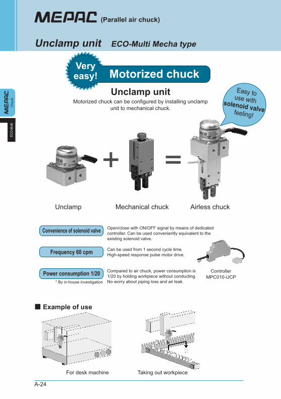
Open/close with ON/OFF signal by means of dedicated controller. Can be used conveniently equivalent to the existing solenoid valve.
Chu
ckEC
O-M
ulti
(Parallel air chuck)
Unclamp unit ECO-Multi Mecha type
Motorized chuckVeryeasy!
Convenience of solenoid valve
Can be used from 1 second cycle time. High-speed response pulse motor drive.Frequency 60 cpm
Compared to air chuck, power consumption is 1/20 by holding workpiece without conducting. No worry about piping loss and air leak.
Power consumption 1/20
Unclamp unit
Airless chuckMechanical chuckUnclamp
Easy touse withsolenoid valve feeling!
■ Example of use
For desk machine
ControllerMPC010-UCP
Taking out workpiece
* By in-house investigation
Motorized chuck can be configured by installing unclamp unit to mechanical chuck.
A-25
Chuck
Eco model
ECO-M
ulti
Unclamp unit
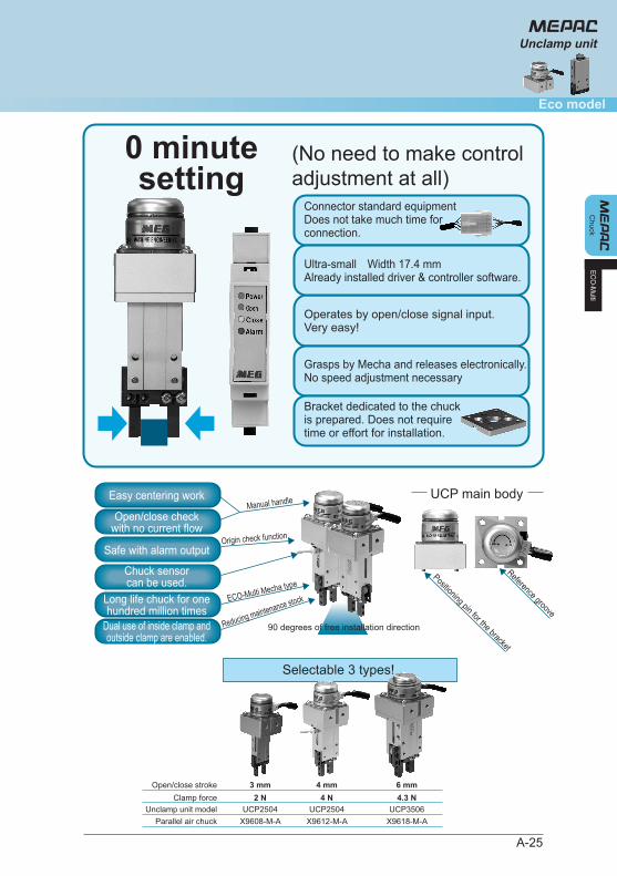
0 minutesetting
(No need to make control adjustment at all)
Connector standard equipmentDoes not take much time for connection.
Easy centering work
Open/close checkwith no current flow
Safe with alarm output
Chuck sensorcan be used.
Long life chuck for onehundred million times
Dual use of inside clamp andoutside clamp are enabled.
Operates by open/close signal input.Very easy!
Grasps by Mecha and releases electronically.No speed adjustment necessary
Bracket dedicated to the chuckis prepared. Does not requiretime or effort for installation.
Ultra-small Width 17.4 mmAlready installed driver & controller software.
UCP main bodyManual handle
Origin check function
ECO-Multi Mecha type
Reducing maintenance stock
Positioning pin for the bracket
Reference groove
90 degrees of free installation direction
Selectable 3 types!
Open/close stroke 3 mm 4 mm 6 mmClamp force 2 N 4 N 4.3 N
Unclamp unit model UCP2504 UCP2504 UCP3506Parallel air chuck X9608-M-A X9612-M-A X9618-M-A
A-26
●
●
●
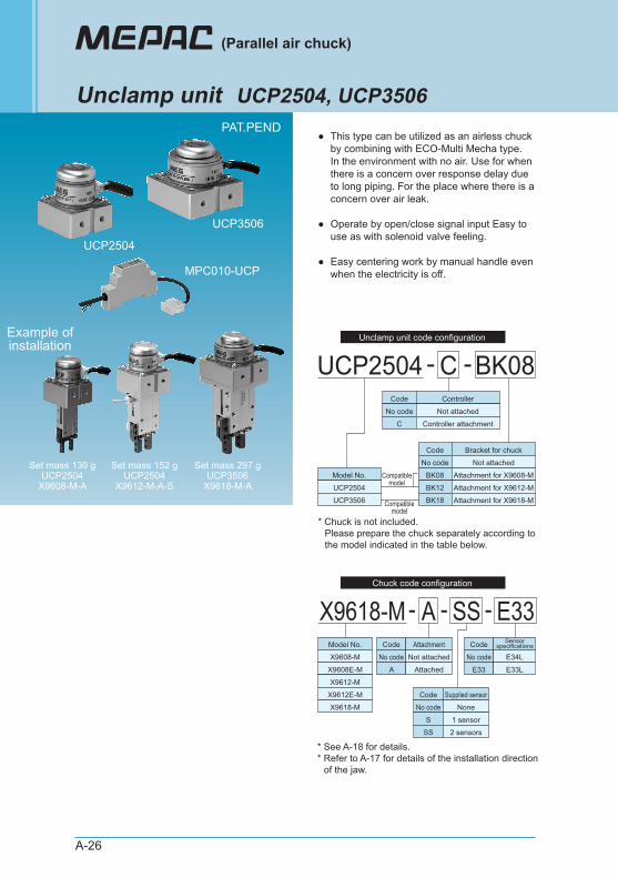
This type can be utilized as an airless chuck by combining with ECO-Multi Mecha type. In the environment with no air. Use for when there is a concern over response delay due to long piping. For the place where there is a concern over air leak.
Operate by open/close signal input Easy to use as with solenoid valve feeling.
Easy centering work by manual handle even when the electricity is off.
(Parallel air chuck)
Unclamp unit UCP2504, UCP3506
UCP2504 - -C BK08
MPC010-UCP
UCP2504
UCP3506
Set mass 130 gUCP2504
X9608-M-A
Set mass 152 gUCP2504
X9612-M-A-S
Example ofinstallation
Set mass 297 gUCP3506
X9618-M-A
PAT.PEND
Unclamp unit code configuration
Code Controller
Model No.
* Chuck is not included. Please prepare the chuck separately according to the model indicated in the table below.
* See A-18 for details. * Refer to A-17 for details of the installation direction of the jaw.
UCP2504
UCP3506
No code Not attached
C Controller attachment
Code Bracket for chuck
No code Not attached
BK08 Attachment for X9608-M
BK12 Attachment for X9612-M
BK18 Attachment for X9618-M
Compatiblemodel
Compatiblemodel
X9618-M- -A SSChuck code configuration
- E33Code AttachmentModel No.
X9608-M
X9608E-M
X9612-M
X9612E-M
X9618-M
No code Not attached
A Attached
Code Supplied sensor
No code None
S 1 sensor
SS 2 sensors
Code Sensorspecifications
No code E34L
E33 E33L
A-27
Chuck
Eco model
ECO-M
ulti
Unclamp unit
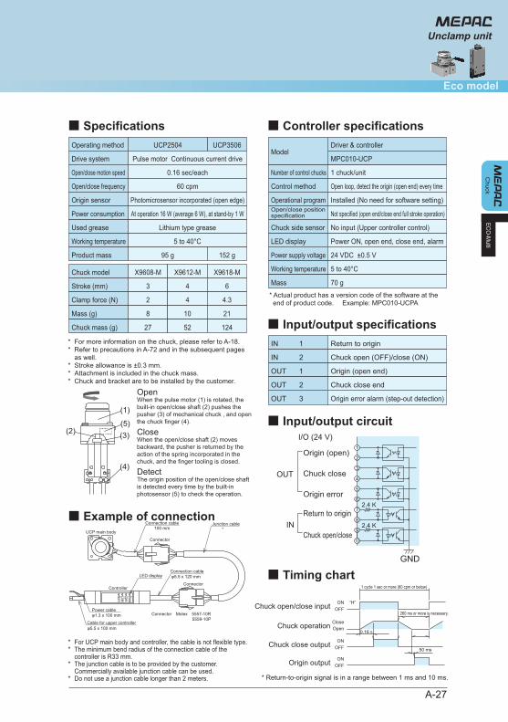
■ Specifications
■ Example of connection
Operating method UCP3506UCP2504
Drive system Pulse motor Continuous current drive
Open/close motion speed 0.16 sec/each
Open/close frequency 60 cpm
Origin sensor Photomicrosensor incorporated (open edge)
Power consumption At operation 16 W (average 6 W), at stand-by 1 W
Used grease Lithium type grease
Working temperature 5 to 40°C
Product mass 95 g 152 g
Chuck model X9608-M X9612-M X9618-M
Stroke (mm) 3 4 6
Clamp force (N) 2 4 4.3
Mass (g) 8 10 21
Chuck mass (g) 27 52 124
**
***
For more information on the chuck, please refer to A-18. Refer to precautions in A-72 and in the subsequent pages as well. Stroke allowance is ±0.3 mm. Attachment is included in the chuck mass. Chuck and bracket are to be installed by the customer.
**
* *
For UCP main body and controller, the cable is not flexible type. The minimum bend radius of the connection cable of the controller is R33 mm. The junction cable is to be provided by the customer. Commercially available junction cable can be used. Do not use a junction cable longer than 2 meters.
■ Controller specifications
Number of control chucks 1 chuck/unit
ModelDriver & controller
MPC010-UCP
Open loop, detect the origin (open end) every time
Installed (No need for software setting)
No input (Upper controller control)
24 VDC ±0.5 V
Control method
Operational program
Not specified (open end/close end full stroke operation)Open/close positionspecification
Power ON, open end, close end, alarmLED display
Chuck side sensor
■ Input/output specifications
■ Input/output circuit
■ Timing chart
IN Return to origin
Chuck open (OFF)/close (ON)
Origin (open end)
Origin error alarm (step-out detection)
IN
OUT
Chuck close endOUT
OUT
1
2
1
2
3
Power supply voltage
5 to 40°CWorking temperature
70 gMass
(4)
(2)
(1)
(3)(5)
φ1.3 x 100 mm
Controller
φ5.5 x 100 mm
UCP main body
Connector
Connector
φ5.5 x 120 mm
100 mm
Connector Molex 5557-10R5559-10P
Power cable
Cable for upper controller
Junction cable*
Connection cable
Connection cableLED display
PowerOpenCloseAlarm
When the pulse motor (1) is rotated, the built-in open/close shaft (2) pushes the pusher (3) of mechanical chuck , and open the chuck finger (4).
Open
When the open/close shaft (2) moves backward, the pusher is returned by the action of the spring incorporated in the chuck, and the finger tooling is closed.
Close
The origin position of the open/close shaft is detected every time by the built-in photosensor (5) to check the operation.
Detect
I/O (24 V)
2.4 K
1
2
3
4
7
8
Origin (open)
Chuck close
5
6Origin error
OUT
Return to originIN 2.4 K
9
10Chuck open/close
GND
Chuck open/close input ON “H”OFF
CloseChuck operation Open
ONOFFChuck close output
ONOFFOrigin output
50 ms
0.16s
1 cycle 1 sec or more (60 cpm or below)
* Return-to-origin signal is in a range between 1 ms and 10 ms.
260 ms or more is necessary.
* Actual product has a version code of the software at the end of product code. Example: MPC010-UCPA
A-28
Chu
ck
(Parallel air chuck)
Unclamp unit
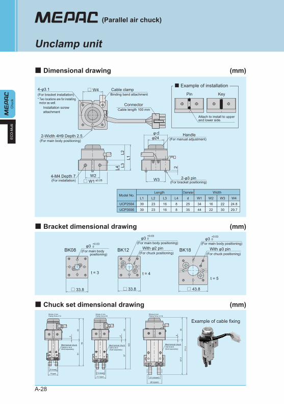
■ Dimensional drawing (mm)
■ Bracket dimensional drawing (mm)
■ Chuck set dimensional drawing (mm)
■ Example of installation
EC
O-M
ulti
2L3L2
L1
L4
W2□ W1 ±0.05
□ W4
W34-M4 Depth 7 2-φ3 pin
φd2-Width 4H9 Depth 2.5 φ24
Handle
4-φ3.1 Cable clamp
Connector
Pin Key
Cable length 100 mm
(For manual adjustment)
(For bracket positioning)(For installation)
(For main body positioning)
(For bracket installation)* Two locations are for installing motor as well.
Installation screwattachment
Binding band attachment
Attach to install to upperand lower side.
L1 L2 L3 L4 d W1 W2 W3 W4
39 23 16 8 25 34 16 22 24.8
39 23 16 8 35 44 22 30 29.7
Length WidthDiameterModel No.
UCP2504
UCP3506
With φ2 pinφ3
□ 33.8
t = 3 t = 4t = 5
BK08 BK12 BK18
□ 33.8 □ 43.8
With φ3 pin(For main body positioning)
φ3(For main body positioning)
φ3(For main body positioning)
(For chuck positioning) (For chuck positioning)
Clamp force 2 NStroke 3 mm
Clamp force 4NStroke 4 mm
Clamp force 4.3 NStroke 6 mm
X9608-E-M-A(Sold separately)
X9612-M-A(Sold separately) (Sold separately)
X9618-M-A
17.2 (closed)
21.2 (open)
16 (closed)
19 (open)
Mechanical chuck Mechanical chuck
23 (closed)
29 (open)
Mechanical chuck
67.3
44
111.
3
5743
100
5142
93
543
Example of cable fixing
+0.030
+0.030
+0.030
A-29
Chuck
Eco model
ECO-M
ulti
Unclamp unit
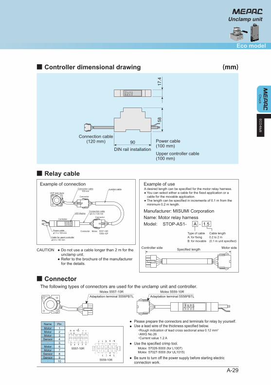
■ Controller dimensional drawing (mm)
■ Relay cable
■ Connector
CAUTION ● Do not use a cable longer than 2 m for the unclamp unit.
● Refer to the brochure of the manufacturer for the details.
●●
Please prepare the connectors and terminals for relay by yourself. Use a lead wire of the thickness specified below.
● Use the specified crimp tool.
● Be sure to turn off the power supply before starting electric connection work.
17.4
58
DIN rail installation90
Upper controller cable(100 mm)
Power cable(100 mm)
Connection cable(120 mm)
Powe
rOp
enClo
seAla
rm
φ1.3 x 100 mm
Controller
φ5.5 x 100 mm
UCP main body
Example of connection Example of use
Manufacturer: MISUMI CorporationName: Motor relay harnessModel: STOP-AS1- -A
Type of cableA: for fixingB: for movable
Cable length0.2 to 2 m(0.1 m unit specified)
Connector
Connector
φ5.5 x 120 mm
100 mm
Connector Molex 5557-10R5559-10P
Power cable
Cable for upper controller
Junction cable*
Connection cable
Connection cableLED display
PowerOpenCloseAlarm
Controller side Specified length Motor side
1.5
Power
Open
Close
Alarm
The following types of connectors are used for the unclamp unit and controller.Molex 5557-10R
Adaptation terminal 5556PBTLMolex 5559-10R
Adaptation terminal 5558PBTL
・Rough indication of lead cross sectional area 0.12 mm2
・AWG No.26・Current value 1.2 A
Molex 57026-5000 (for L1007) Molex 57027-5000 (for UL1015)
Pin12
NameMotorMotor
34
MotorSensor
56
‐Motor
78
MotorSensor
910
Sensor‐
5557-10R
5559-10R
A desired length can be specified for the motor relay harness. ● You can select either a cable for the fixed application or a
cable for the movable application. ● The length can be specified in increments of 0.1 m from the
minimum 0.2 m length.
A-30
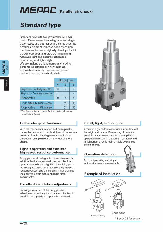
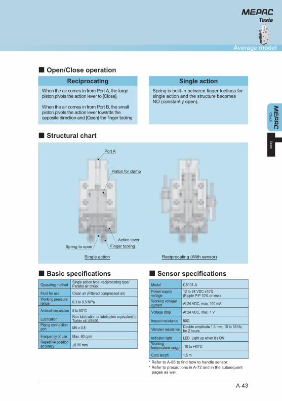
Standard type with two jaws called MEPAC basic. There are reciprocating type and single action type, and both types are highly accurate parallel slide air chuck developed by original mechanism that was originally developed not to burden operation and precision machining. Achieved light and assured action and downsizing and lightweight. We are making achievements as chucking parts for industrial machinery such as automatic assembly machine and carrier device, including industrial robots.
(Parallel air chuck)
Standard type
With the mechanism to open and close parallel, the contact surface of the chuck to workpiece stays constant. Stable chucking even when there is variation in clamp dimension and with different shape.
Stable clamp performance
Apply parallel air swing action lever structure. In addition, built in super-small precise roller that operates smoothly and lightly in the sliding parts. No engaging phenomena, excellent high-speed responsiveness, and a mechanism that provides the ability to obtain sufficient clamp force concurrently.
Light in operation and excellent high-speed response performance.
By fixing shank part of the body, position adjustment of the height and rotation direction is possible and speedy set-up can be achieved.
Excellent installation adjustment
Achieved high performance with a small body of the original structure. Downsizing of device is possible. No unreasonable force is applied to operation direction, and excellent durability and initial performance is maintainable over a long period of time.
Small, light, and long life
Both reciprocating and single action with sensor are available.
Operation detection
Example of installation
5Single action Constantly open (NO)
Stroke (mm)
×4×
6×
Single action Constantly closed (NC) × ×
Single action (NO) With sensorReciprocating With sensor
* The figure within ( ) stands for the number of sensor installations (max).
(1) (1)(1)
Reciprocating ×× ×
Chu
ckS
tand
ard
(1)
ReciprocatingSingle action
* See A-74 for details.
A-31
Standard
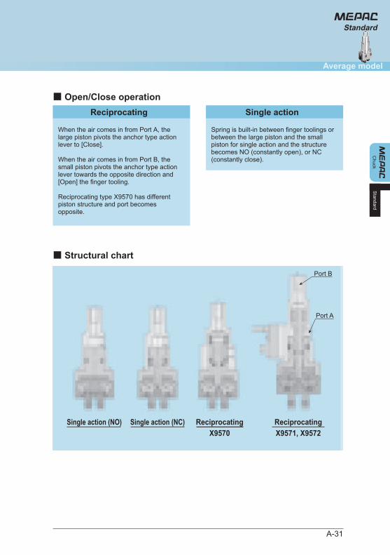
■ Open/Close operation
■ Structural chart
Standard
Chuck
Reciprocating
When the air comes in from Port A, the large piston pivots the anchor type action lever to [Close].
When the air comes in from Port B, the small piston pivots the anchor type action lever towards the opposite direction and [Open] the finger tooling.
Reciprocating type X9570 has different piston structure and port becomes opposite.
Single action
Spring is built-in between finger toolings or between the large piston and the small piston for single action and the structure becomes NO (constantly open), or NC (constantly close).
Single action (NO) Single action (NC) ReciprocatingX9570
ReciprocatingX9571, X9572
Average model
Port A
Port B

A-32
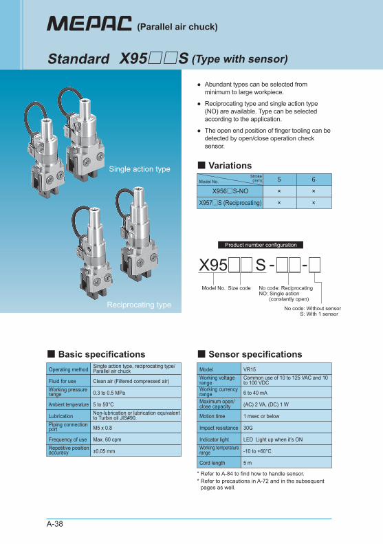
●
●
Abundant types can be selected from minimum to large workpiece.
Reciprocating type and single action type (NO, NC) are available. Type can be selected according to the application.
Operating methodSingle action type, reciprocating type/Parallel air chuck
Clean air (Filtered compressed air)
0.3 to 0.5 MPa
Max. 60 cpm
±0.05 mm
Fluid for use
Working pressure range
5 to 50°CAmbient temperatureNon-lubrication or lubrication equivalent to Turbin oil JIS#90.Lubrication
Frequency of use
M5 x 0.8Piping connection port
Repetitive position accuracy
X95 -Model No. Size code No code: Reciprocating
NO: Single action (constantly open)NC: Single action (constantly closed)
4 5 6
X95□□-NO × × ×
X95□□-NC × ×
X95□□ (Reciprocating) × × ×
Model No.Stroke
(mm)
(Parallel air chuck)
Standard X95□□ (Type without sensor)
■ Basic specifications
■ Variations
* Refer to A-38 to find the type with sensor.Single action type
Reciprocating type
* Refer to precautions in A-72 and in the subsequent pages as well.
Product number configuration
A-33
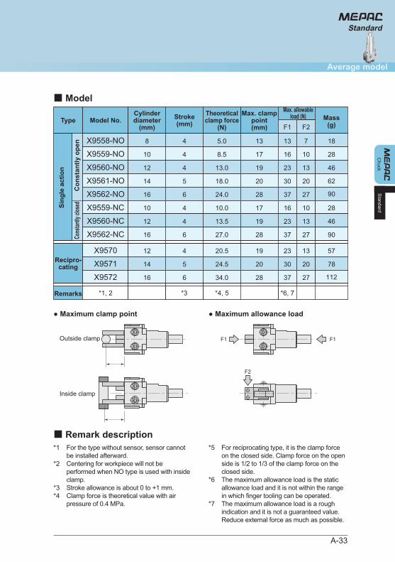
● Maximum clamp point ● Maximum allowance load
*1
*2
*3*4
For the type without sensor, sensor cannot be installed afterward. Centering for workpiece will not be performed when NO type is used with inside clamp. Stroke allowance is about 0 to +1 mm. Clamp force is theoretical value with air pressure of 0.4 MPa.
*5
*6
*7
For reciprocating type, it is the clamp force on the closed side. Clamp force on the open side is 1/2 to 1/3 of the clamp force on the closed side. The maximum allowance load is the static allowance load and it is not within the range in which finger tooling can be operated. The maximum allowance load is a rough indication and it is not a guaranteed value. Reduce external force as much as possible.
X9570
X9571
4
5
20.5
24.5
19
20
23
30
13
20
57
78
X9572
X9558-NO
6
4
34.0
5.0
28
13
37
13
27
7 18
X9559-NO
X9560-NO
4
4
8.5
13.0
17
19
16
23
10
13
28
X9561-NO
X9562-NO
5
6
18.0
24.0
20
28
30
37
20
27
X9559-NC
X9560-NC
4
4
10.0
13.5
17
19
16
23
10
13
28
X9562-NC 6 27.0 28 37 27 90
*1, 2
F1 F2
*4, 5*3 *6, 7
112
62
90
46
46
F1
F2
F1Outside clamp
Inside clamp
Type
Recipro-cating
Sing
le a
ctio
n
Remarks
Model No.Max. allowable
load (N)Stroke(mm)
12
14
16
8
10
12
14
16
10
12
16
Cylinderdiameter
(mm)Mass
(g)
Max. clamppoint(mm)
Theoreticalclamp force
(N)
■ Model
■ Remark description
Con
stan
tly o
pen
Cons
tantly
clos
ed
Standard
Chuck
Average model
Standard
A-34
0.2
0.25
0.3
0.40.5
3 4 5 10 20 30 40 50 100
Clamp force of jaw (N)A
ir w
orki
ng p
ress
ure
(MP
a)
X9559
-NCX95
60-NC
X9562
-NC
Single action type - NC (open force)
0.2
0.25
0.3
0.40.5
3 4 5 10 20 30 40 50 100
Clamp force of jaw (N)
Air
wor
king
pre
ssur
e (M
Pa)
X9558-NO
X9559-NO
X9560-NO
X9561-NO
X9562-NO
Single action type - NO (close force)
Chu
ckS
tand
ard
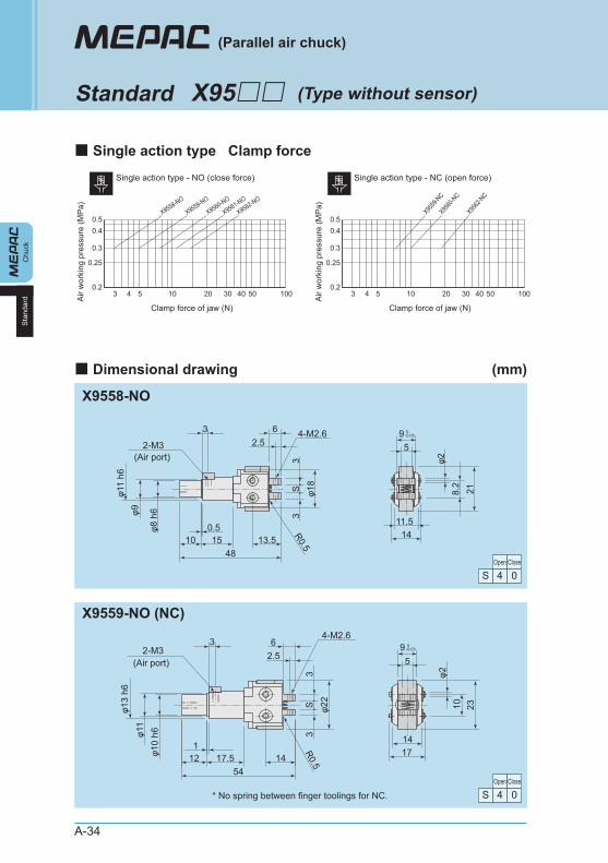
(Type without sensor)
(Parallel air chuck)
Standard X95□□
■ Single action type Clamp force
■ Dimensional drawing (mm)
X9558-NO
* No spring between finger toolings for NC.
X9559-NO (NC)
Open Close
4S 0
Open Close
4S 0
2-M3 5
1411.5
R0.5φ1
83
S3
φ11
h6φ9
φ8 h
6
218.2
φ24-M2.6
(Air port)
3 62.5
4813.51510
0.5
2-M35
1714
φ13
h6φ1
1φ1
0 h6
φ22
3S
3R0.5
2310φ2
4-M2.66
2.5(Air port)
3
541417.512
1
0-0.039
0-0.059
A-35
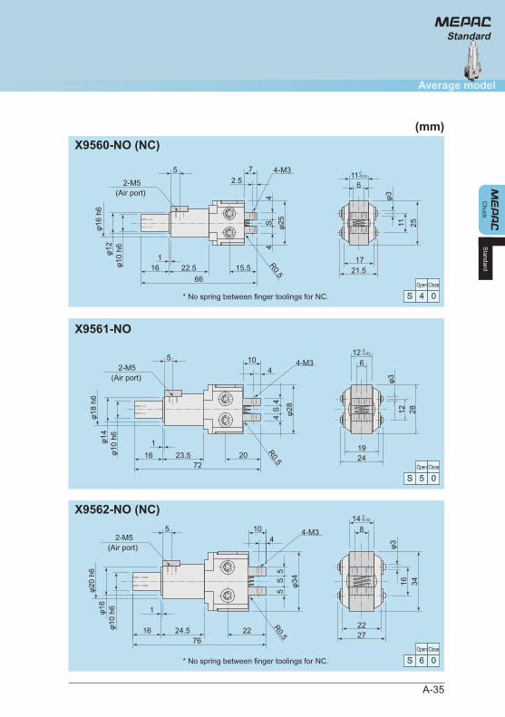
X9560-NO (NC)
X9561-NO
X9562-NO (NC)
Open Close
4S 0
Open Close
5S 0
Open Close
6S 0
Standard
Chuck
Average model
Standard
* No spring between finger toolings for NC.
* No spring between finger toolings for NC.
2-M5
R0.5
116
4S
4φ2
5
φ16
h6φ1
2φ1
0 h6
4-M3
2511φ3
21.517
72.5
(Air port)
5
6615.522.516
1
0-0.03
2419
φ3
104
φ18
h6φ1
4φ1
0 h6
1
7223.516
2812
1264-M3
φ284
S4
5
20
R0.5
2-M5(Air port)
0-0.03
2722
φ3
φ20
h6φ1
6φ1
0 h6
104
7624.516
4-M3
148
3416φ34
5
22
1
R0.5
2-M5(Air port)
5S
5
0-0.03
(mm)
A-36
Chu
ckS
tand
ard
(Type without sensor)
(Parallel air chuck)
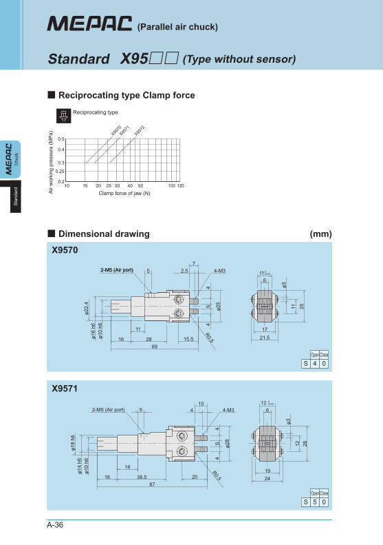
Standard X95□□
■ Reciprocating type Clamp force
■ Dimensional drawing (mm)
X9570
X9571
Open Close4S 0
Open Close5S 0
0.2
0.25
0.3
0.4
0.5
10 15 20 25 30 40 50 100 120Clamp force of jaw (N)A
ir w
orki
ng p
ress
ure
(MP
a) X9570
X9571
X9572
Reciprocating type
116
21.517R0.5
φ25
4S
4
φ22.
4φ1
6 h6
φ10
h6
6915.52816
11
2511
φ3
2-M5 (Air port)2-M5 (Air port) 4-M357
2.5
R0.5
104
φ28
4S
4
φ18
h6φ1
4 h6
φ10
h6
2087
38.516
2812
φ3
126
2419
5 4-M3
16
2-M5 (Air port)
0-0.03
0-0.03
A-37
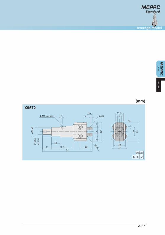
X9572
Open Close6S 0
Standard
104
R0.5
φ34
5S
5
912239.516
φ20
h6φ1
6 h6
φ10
h6
2722
1485 4-M3
16
3416
φ3
2-M5 (Air port)
0-0.03
StandardC
huck
Average model
(mm)
A-38
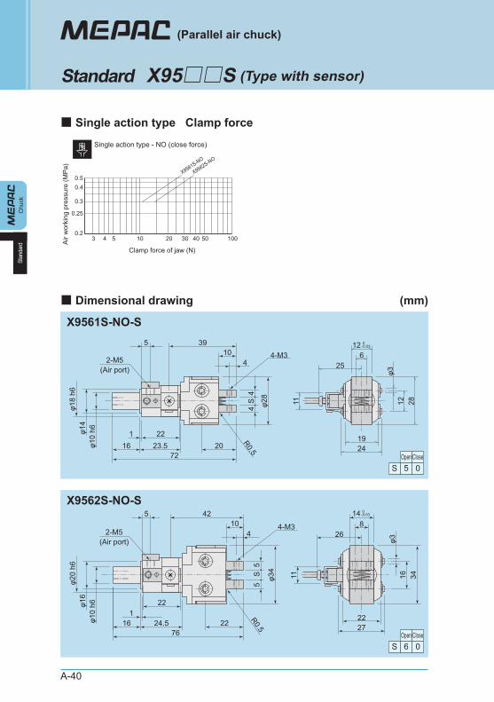
●
●
●
Abundant types can be selected from minimum to large workpiece.
Reciprocating type and single action type (NO) are available. Type can be selected according to the application.
The open end position of finger tooling can be detected by open/close operation check sensor.
Operating method Single action type, reciprocating type/Parallel air chuck
Clean air (Filtered compressed air)
0.3 to 0.5 MPa
Max. 60 cpm
±0.05 mm
Fluid for useWorking pressurerange
5 to 50°CAmbient temperatureNon-lubrication or lubrication equivalent to Turbin oil JIS#90.Lubrication
Frequency of use
M5 x 0.8Piping connectionport
Repetitive positionaccuracy
Model VR15Common use of 10 to 125 VAC and 10to 100 VDC
6 to 40 mA
LED Light up when it’s ON
-10 to +60°C
5 m
Working voltagerangeWorking currencyrange
(AC) 2 VA, (DC) 1 WMaximum open/close capacity
1 msec or belowMotion time
Indicator light
30GImpact resistance
Working temperature range
Cord length
* Refer to A-84 to find how to handle sensor.
X95 S -Model No. Size code No code: Reciprocating
NO: Single action (constantly open)
No code: Without sensor S: With 1 sensor
-
5 6
X956□S-NO × ×
X957□S (Reciprocating) × ×
Model No.Stroke
(mm)
(Type with sensor)
(Parallel air chuck)
Standard X95□□S
■ Basic specifications
Single action type
Reciprocating type
■ Sensor specifications
■ Variations
* Refer to precautions in A-72 and in the subsequent pages as well.
Product number configuration
A-39
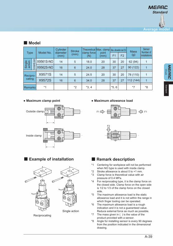
● Maximum clamp point ● Maximum allowance load
*1
*2*3
*4
*5
*6
*7
*8
Centering for workpiece will not be performed when NO type is used with inside clamp. Stroke allowance is about 0 to +1 mm. Clamp force is theoretical value with air pressure of 0.4 MPa. For reciprocating type, it is the clamp force on the closed side. Clamp force on the open side is 1/2 to 1/3 of the clamp force on the closed side. The maximum allowance load is the static allowance load and it is not within the range in which finger tooling can be operated. The maximum allowance load is a rough indication and it is not a guaranteed value. Reduce external force as much as possible. The mass given in ( ) is the value of the product provided with a sensor. Angle for installing sensor is every 90 degrees from the position indicated in the dimensional drawing.
X9571S 5 24.5 20 30 20 78 (110)
X9572S 6 34.0 28 37 27
X9561S-NO
X9562S-NO
5
6
18.0
24.0
20
28
30
37
20
27
*1
F1 F2
*3, 4*2 *5, 6 *7 *8
112 (144)
62 (94)
90 (122)
F1
F2
F1Outside clamp
Inside clamp
Type
Recipro-cating
Sin
gle
actio
n
Remarks
Model No.Max. allowable load (N)Stroke
(mm)
14
16
14
16
Cylinderdiameter
(mm)Mass
(g)
Max. clamppoint(mm)
1
1
1
1
SensorNumber of
installations
Theoreticalclamp force
(N)
■ Model
■ Remark description
Const
antly
open
Standard
Chuck
Average model
Standard
■ Example of installation
ReciprocatingSingle action
A-40
0.2
0.25
0.3
0.40.5
3 4 5 10 20 30 40 50 100
Clamp force of jaw (N)
Air
wor
king
pre
ssur
e (M
Pa)
X9561S-NO
X9562S-NO
Single action type - NO (close force)
X9561S-NO-S
X9562S-NO-S
Open Close5S 0
Open Close6S 0
2419
φ3
11
3910
4
φ18
h6φ1
4φ1
0 h6 221
7223.516
2812
25
1264-M3
φ284
S4
5
20
R0.5
2-M5(Air port)
0-0.03
2722
φ3
11
φ20
h6φ1
6φ1
0 h6
4210
4
7624.516
22
4-M326
148
3416φ34
5
221 R0.5
2-M5(Air port)
5S
5
0-0.03
Chu
ckSt
anda
rd
(Type with sensor)X95□□S
(Parallel air chuck)
Standard
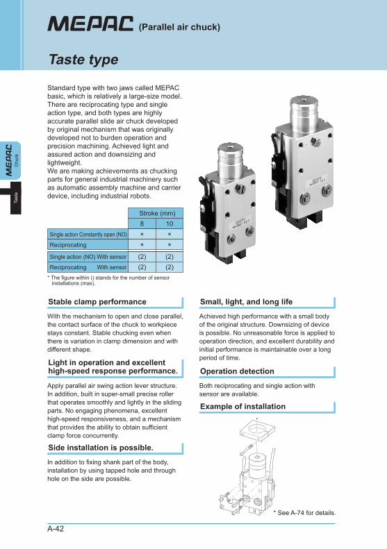
■ Single action type Clamp force
■ Dimensional drawing (mm)
A-41
■ Reciprocating type Clamp force
X9571S-S
Open Close5S 0
0.2
0.25
0.3
0.4
0.5
10 15 20 25 30 40 50 100 120Clamp force of jaw (N)
Air
wor
king
pre
ssur
e (M
Pa)
X9571
S-SX95
72S-S
Reciprocating type
11
R0.5
3910
4
φ28
4S
4
φ18
h6φ1
4 h6
φ10
h6
2087
38.516
222812
φ3
25
126
2419
5 4-M3
16
2-M5 (Air port)
0-0.03
X9572S-S
Open Close6S 0
4210
4
R0.5
φ34
5S
5
912239.516
22
φ20
h6φ1
6 h6
φ10
h6
26
11
2722
1485 4-M3
16
3416
φ3
2-M5 (Air port)
0-0.03
Standard
Chuck
Average model
Standard
(mm)
A-42
Standard type with two jaws called MEPAC basic, which is relatively a large-size model. There are reciprocating type and single action type, and both types are highly accurate parallel slide air chuck developed by original mechanism that was originally developed not to burden operation and precision machining. Achieved light and assured action and downsizing and lightweight. We are making achievements as chucking parts for general industrial machinery such as automatic assembly machine and carrier device, including industrial robots.
Chu
ckTa
ste
(Parallel air chuck)
Taste type
With the mechanism to open and close parallel, the contact surface of the chuck to workpiece stays constant. Stable chucking even when there is variation in clamp dimension and with different shape.
Stable clamp performance
Apply parallel air swing action lever structure. In addition, built in super-small precise roller that operates smoothly and lightly in the sliding parts. No engaging phenomena, excellent high-speed responsiveness, and a mechanism that provides the ability to obtain sufficient clamp force concurrently.
Light in operation and excellent high-speed response performance.
In addition to fixing shank part of the body, installation by using tapped hole and through hole on the side are possible.
Side installation is possible.
Achieved high performance with a small body of the original structure. Downsizing of device is possible. No unreasonable force is applied to operation direction, and excellent durability and initial performance is maintainable over a long period of time.
Small, light, and long life
Both reciprocating and single action with sensor are available.
Operation detection
Example of installation
8Single action Constantly open (NO)
Stroke (mm)
×10×
Single action (NO) With sensor
Reciprocating With sensor
* The figure within () stands for the number of sensor installations (max).
(2) (2)(2)
Reciprocating × ×
(2)
* See A-74 for details.
A-43
Chuck
Average model
Taste
■ Open/Close operationReciprocating
When the air comes in from Port A, the large piston pivots the action lever to [Close].
When the air comes in from Port B, the small piston pivots the action lever towards the opposite direction and [Open] the finger tooling.
Single actionSpring is built-in between finger toolings for single action and the structure becomes NO (constantly open).
■ Structural chart
Operating method Single action type, reciprocating type/Parallel air chuck
Clean air (Filtered compressed air)
0.3 to 0.5 MPa
Max. 60 cpm
±0.05 mm
Fluid for useWorking pressurerange
5 to 50°CAmbient temperatureNon-lubrication or lubrication equivalent toTurbin oil JIS#90.Lubrication
Frequency of use
M5 x 0.8Piping connectionport
Repetitive positionaccuracy
Model CS101-A12 to 24 VDC ±10%(Ripple P-P 10% or less)
At 24 VDC, max. 100 mA
LED Light up when it’s ON
-10 to +60°C
1.5 m
Power supplyvoltageWorking voltage/current
At 24 VDC, max. 1 VVoltage drop
50GImpact resistance
Indicator light
Double amplitude 1.5 mm, 10 to 55 Hz, for 2 hoursVibration resistance
Workingtemperature range
Cord length
* Refer to A-86 to find how to handle sensor.
■ Basic specifications ■ Sensor specifications
* Refer to precautions in A-72 and in the subsequent pages as well.
Taste
Single action Reciprocating (With sensor)
Port A
Action leverFinger toolingSpring to open
Piston for clamp
A-44
●
●
●
Side installation is possible by using the mounting hole for the main body.
Reciprocating type and single action type (NO) are available. Type can be selected according to the application.
Position of finger tooling can be detected by open/close operation check sensor.
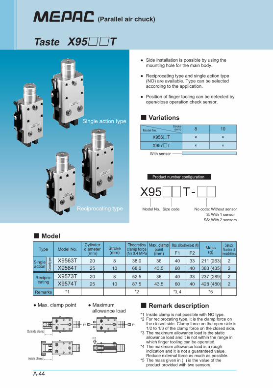
X95 T-Model No. Size code No code: Without sensor
S: With 1 sensor SS: With 2 sensors
With sensor
8 10
X956□T × ×
X957□T × ×
Model No.Stroke
(mm)
(Parallel air chuck)
Taste X95□□T
■ VariationsSingle action type
Reciprocating type
X9573TX9574T
810
52.587.5
3643.5
4060
3340
237 (289)428 (480)
X9563T 8 38.0 36 40 33X9564T 10 68.0 43.5 60 40
*1 *2 *3, 4 *5
211 (263)383 (435)
● Max. clamp point ● Maximum allowance load
F1
F2
F1
Outside clamp
Inside clamp
F1 F2Type Model No.
Max. allowable load (N)Stroke(mm)
2025
2025
Cylinderdiameter
(mm)Mass
(g)
22
22
SensorNumber ofinstallations
Max. clamppoint(mm)
Theoreticaclamp force(N) 0.4 MPa
■ Model
Recipro-cating
Singleaction
Remarks
Consta
ntly op
en
*1*2
*3
*4
*5
Inside clamp is not possible with NO type. For reciprocating type, it is the clamp force on the closed side. Clamp force on the open side is 1/2 to 1/3 of the clamp force on the closed side. The maximum allowance load is the static allowance load and it is not within the range in which finger tooling can be operated. The maximum allowance load is a rough indication and it is not a guaranteed value. Reduce external force as much as possible. The mass given in ( ) is the value of the product provided with two sensors.
■ Remark description
Product number configuration
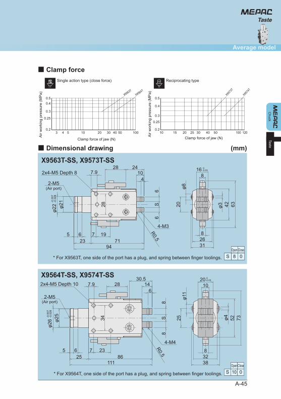
■ Dimensional drawing (mm)
X9563T-SS, X9573T-SS
Open Close8S 0* For X9563T, one side of the port has a plug, and spring between finger toolings.
4-M3
28
2x4-M5 Depth 8 107.9
2-M5(Air port)
(Air port)
31268
168
6342φ320φ8
2428
4
φ22
-0.0
07-0
.028
φ26
-0.0
07-0
.028
φ21
R0.5
6S
6
947123
65 197
0-0.03
X9564T-SS, X9574T-SS
Open Close10S 0* For X9564T, one side of the port has a plug, and spring between finger toolings.
2x4-M5 Depth 10
2-M5
4-M4
147.9
34
2010
38328
7352φ425φ1
1
φ25
R0.5
8S
8
30.5
628
1118625
65 237
0-0.03
A-45
Chuck
Average model
Taste
Taste
0.2
0.25
0.3
0.40.5
3 4 5 10 20 30 40 50 100
Clamp force of jaw (N)
Air
wor
king
pre
ssur
e (M
Pa) X9563T
X9564T
Single action type (close force)
0.2
0.25
0.3
0.4
0.5
10 15 20 25 30 40 50 100 120Clamp force of jaw (N)A
ir w
orki
ng p
ress
ure
(MP
a) X9573
T
X9574
T
Reciprocating type
■ Clamp force
Chu
ckA
ll-pu
rpos
e
All-purpose type
A-46
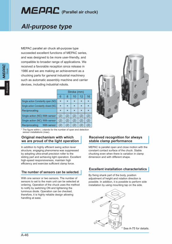
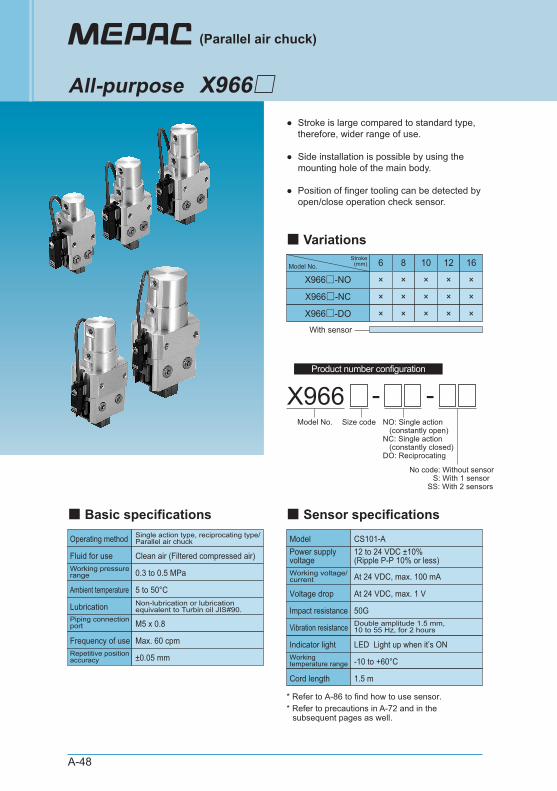
MEPAC parallel air chuck all-purpose type succeeded excellent functions of MEPAC series, and was designed to be more user-friendly, and compatible to broader range of applications. We received a favorable reception since release in 1986 and we are making an achievement as a chucking parts for general industrial machinery such as automatic assembly machine and carrier devices, including industrial robots.
In addition to highly efficient swing action lever structure, engaging phenomena was suppressed by adopting ultra-small precision roller to the sliding part and achieving light operation. Excellent high-speed responsiveness, maintain high efficiency and exercise sufficient clamp force.
With one sensor or two sensors. The number of sensors to set to the main unit can be selected at ordering. Operation of the chuck uses the method to notify by switching ON and lightening the luminous diode. Operation can be checked, therefore, it is highly reliable design allowing handling at ease.
MEPAC is parallel open and close motion with the constant contact surface of the chuck. Stable chucking even when there is variation in clamp dimension and with different shape.
By fixing shank part of the body, position adjustment of height and rotation direction is possible. In addition, it is possible to perform side installation by using mounting tap on the side.
(Parallel air chuck)
6Single action Constantly open (NO)
Stroke (mm)
×8×
Single action (NO) With sensor
Single action (NC) With sensor
* The figure within ( ) stands for the number of open end detection sensor installations (max).
(2) (2)(2)
Single action Constantly closed (NC) × ×
(2)
10×
(2)
×
(2)
12×
(2)
×
(2)
16×
(2)
×Reciprocating × × × × ×
(2)Reciprocating With sensor (2) (2) (2) (2) (2)
Original mechanism with which we are proud of the light operation
Received recognition for always stable clamp performance
The number of sensors can be selected.Excellent installation characteristics
* See A-75 for details.
Chuck
Average model
All-purpose
A-47
All-purpose
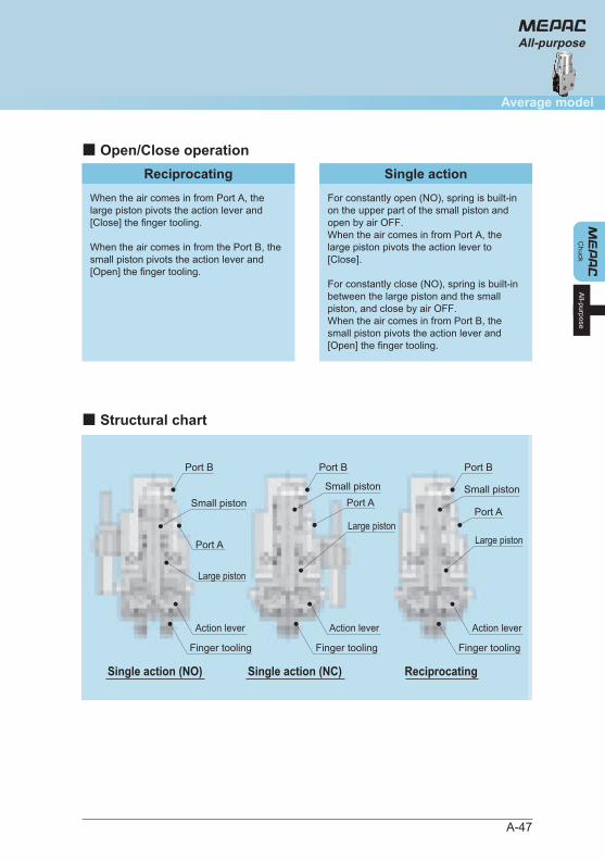
■ Open/Close operation
When the air comes in from Port A, the large piston pivots the action lever and [Close] the finger tooling.
When the air comes in from the Port B, the small piston pivots the action lever and [Open] the finger tooling.
Single actionReciprocatingFor constantly open (NO), spring is built-in on the upper part of the small piston and open by air OFF. When the air comes in from Port A, the large piston pivots the action lever to [Close].
For constantly close (NO), spring is built-in between the large piston and the small piston, and close by air OFF. When the air comes in from Port B, the small piston pivots the action lever and [Open] the finger tooling.
■ Structural chart
Single action (NO) Single action (NC) Reciprocating
Port B
Small piston
Action lever
Large piston
Finger tooling
Action lever
Finger tooling
Action lever
Finger tooling
Port B
Small piston
Large piston
Port A
Port A
Port B
Small piston
Large piston
Port A
A-48
●
●
●
Stroke is large compared to standard type, therefore, wider range of use.
Side installation is possible by using the mounting hole of the main body.
Position of finger tooling can be detected by open/close operation check sensor.
Operating method Single action type, reciprocating type/Parallel air chuck
Clean air (Filtered compressed air)
0.3 to 0.5 MPa
Max. 60 cpm
±0.05 mm
Fluid for useWorking pressurerange
5 to 50°CAmbient temperatureNon-lubrication or lubrication equivalent to Turbin oil JIS#90.Lubrication
Frequency of use
M5 x 0.8Piping connectionport
Repetitive positionaccuracy
X966 -Model No. Size code NO: Single action
(constantly open)NC: Single action (constantly closed)DO: Reciprocating
-
No code: Without sensor S: With 1 sensor SS: With 2 sensors
Model No.Stroke
(mm) 6 8
X966□-NO × ×
X966□-NC × ×
10 12
× ×
× ×
16
×
×
X966□-DO × × × × ×
With sensor
Model CS101-A12 to 24 VDC ±10%(Ripple P-P 10% or less)
At 24 VDC, max. 100 mA
LED Light up when it’s ON
-10 to +60°C
1.5 m
Power supply voltageWorking voltage/current
At 24 VDC, max. 1 VVoltage drop
50GImpact resistance
Indicator light
Double amplitude 1.5 mm, 10 to 55 Hz, for 2 hoursVibration resistance
Workingtemperature range
Cord length
* Refer to A-86 to find how to use sensor.
(Parallel air chuck)
All-purpose X966□
■ Basic specifications ■ Sensor specifications
■ Variations
* Refer to precautions in A-72 and in the subsequent pages as well.
Product number configuration
Chuck
Average model
All-purpose
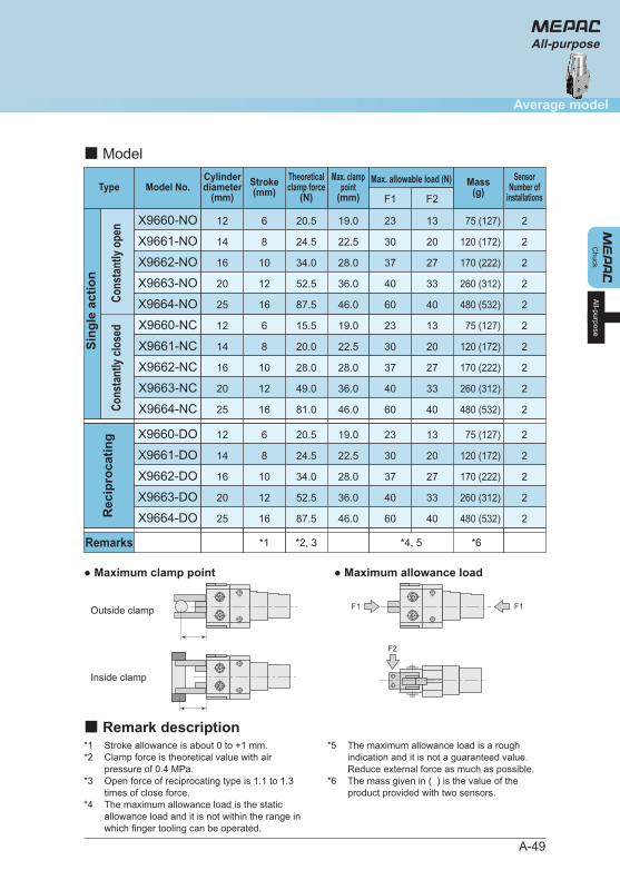
A-49
*1*2
*3
*4
Stroke allowance is about 0 to +1 mm. Clamp force is theoretical value with air pressure of 0.4 MPa. Open force of reciprocating type is 1.1 to 1.3 times of close force. The maximum allowance load is the static allowance load and it is not within the range in which finger tooling can be operated.
*5
*6
The maximum allowance load is a rough indication and it is not a guaranteed value. Reduce external force as much as possible. The mass given in ( ) is the value of the product provided with two sensors.
X9660-NO 6 20.5 19.0 23 13
X9664-DO 16 87.5 46.0 60 40 480 (532)
*2, 3*1
F1 F2
*6*4, 5
X9660-DO
X9661-DO
6
8
20.5
24.5
19.0
22.5
23
30
13
20
75 (127)
75 (127)
120 (172)
X9662-DO 10 34.0 28.0 37 27
X9663-DO 12 52.5 36.0 40 33
170 (222)
260 (312)
X9664-NC 16 81.0 46.0 60 40 480 (532)
X9660-NC
X9661-NC
6
8
15.5
20.0
19.0
22.5
23
30
13
20
75 (127)
120 (172)
X9662-NC 10 28.0 28.0 37 27
X9663-NC 12 49.0 36.0 40 33
170 (222)
260 (312)
X9664-NO 16 87.5 46.0 60 40 480 (532)
X9661-NO 8 24.5 22.5 30 20 120 (172)
X9662-NO 10 34.0 28.0 37 27
X9663-NO 12 52.5 36.0 40 33
170 (222)
260 (312)
● Maximum clamp point ● Maximum allowance load
F1
F2
F1Outside clamp
Inside clamp
All-purpose
Model No.TypeMax. allowable load (N)Stroke
(mm)
12
25
12
14
16
20
25
12
14
16
20
25
14
16
20
Cylinderdiameter
(mm)Mass
(g)Max. clamp
point(mm)
2
2
2
2
2
2
2
2
2
2
2
2
2
2
2
SensorNumber of
installations
Theoreticalclamp force
(N)
■ Model
■ Remark description
Cons
tant
ly op
enCo
nsta
ntly
close
d
Remarks
Rec
ipro
catin
gSi
ngle
act
ion
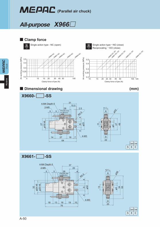
Chu
ckAl
l-pur
pose
A-50
Single action type-NO (close)Reciprocating -DO (close)
Single action type - NC (open)
Clamp force of jaw (N)A
ir w
orki
ng p
ress
ure
(MP
a)Clamp force of jaw (N)
Air
wor
king
pre
ssur
e (M
Pa)
0.2
0.25
0.3
0.4
0.5
5 10 15 20 30 40 50 100
X9660-NC
X9661-NC
X9662-NC
X9663-NC
X9664-NC
0.2
0.25
0.3
0.4
0.5
10 15 20 25 30 40 50 100 120
X9660
-DO, N
O
X9661
-DO, N
O
X9662
-DO, N
O
X9663
-DO, N
O
X9664
-DO, N
O
(Parallel air chuck)
■ Clamp force
■ Dimensional drawing (mm)
All-purpose X966□
X9660- -SS
28
18
φ32
116
228
4927φ3
1127φ1
8 h6
R0.5
φ25
4S
4
5 5
647162714 4-M3
2.5
3115.5
4-M4 Depth 6
(Port side close end detection)
(Port side close end detection)
2-M5
28
20
φ36
5534φ313
258
R0.5
φ32
4S
4
32φ2
4 h6
φ20
h6
3720
761019161318
4-M4 Depth 6
126
4-M3
2-M55 5 4
Open Close6S 0
Open Close8S 0
0-0.03
0-0.03
X9661- -SS
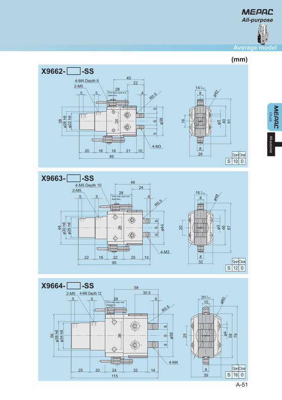
A-51
Chuck
Average model
All-purpose
All-purpose
28
24
φ42
6140φ316
288
148
38φ2
6 h6
φ22
h6
R0.5
φ38
5S
5
4022
851021181620
4-M4 Depth 62-M5
5 5
4-M3
4
28
28
φ48
6746φ320
328
168
R0.5
4624
44φ3
0 h6
φ26
h6
φ44
6S
6
951025221622
4-M5 Depth 102-M5
5 5
4-M3
4
28
φ6020
10
398
7958φ4253656φ3
8 h6
φ34
h6
R0.5
φ56
8S
8
5830.5
1151432242025
4-M4
64-M6 Depth 122-M5
5 5
Open Close10S 0
Open Close12S 0
Open Close16S 0
0-0.03
0-0.03
0-0.03
X9662- -SS
X9663- -SS
X9664- -SS
(Port side close end detection)
(Port side close end detection)
(Port side open end detection)
(mm)
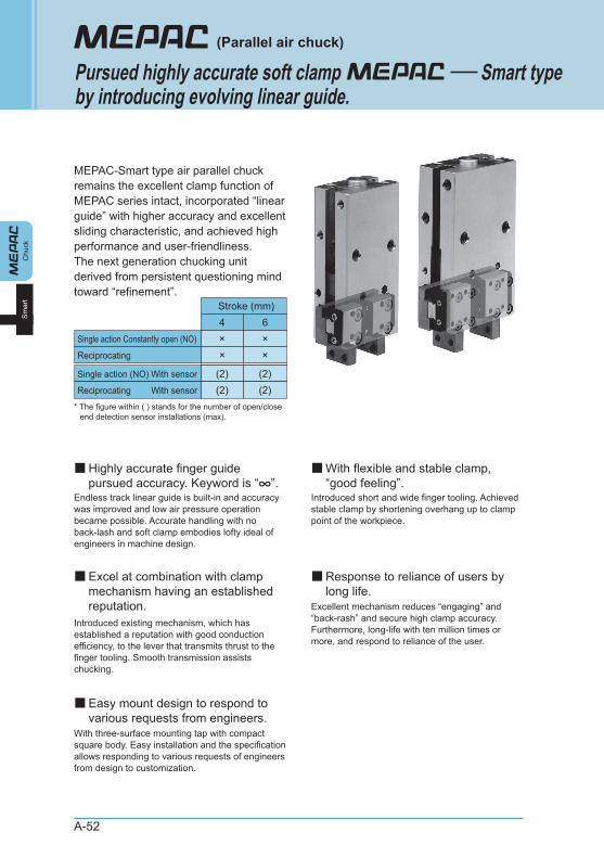
A-52
MEPAC-Smart type air parallel chuck remains the excellent clamp function of MEPAC series intact, incorporated “linear guide” with higher accuracy and excellent sliding characteristic, and achieved high performance and user-friendliness. The next generation chucking unit derived from persistent questioning mind toward “refinement”.
Endless track linear guide is built-in and accuracy was improved and low air pressure operation became possible. Accurate handling with no back-lash and soft clamp embodies lofty ideal of engineers in machine design.
Introduced existing mechanism, which has established a reputation with good conduction efficiency, to the lever that transmits thrust to the finger tooling. Smooth transmission assists chucking.
Introduced short and wide finger tooling. Achieved stable clamp by shortening overhang up to clamp point of the workpiece.
Excellent mechanism reduces “engaging” and “back-rash” and secure high clamp accuracy. Furthermore, long-life with ten million times or more, and respond to reliance of the user.
With three-surface mounting tap with compact square body. Easy installation and the specification allows responding to various requests of engineers from design to customization.
Chu
ckS
mar
t
(Parallel air chuck)
Pursued highly accurate soft clampby introducing evolving linear guide.
Smart type
■Highly accurate finger guide pursued accuracy. Keyword is “∞”.
■With flexible and stable clamp, “good feeling”.
■Excel at combination with clamp mechanism having an established reputation.
■Easy mount design to respond to various requests from engineers.
■Response to reliance of users by long life.
4Single action Constantly open (NO)
Stroke (mm)
×6×
Single action (NO) With sensor
Reciprocating With sensor
* The figure within ( ) stands for the number of open/close end detection sensor installations (max).
(2) (2)(2)
Reciprocating × ×
(2)
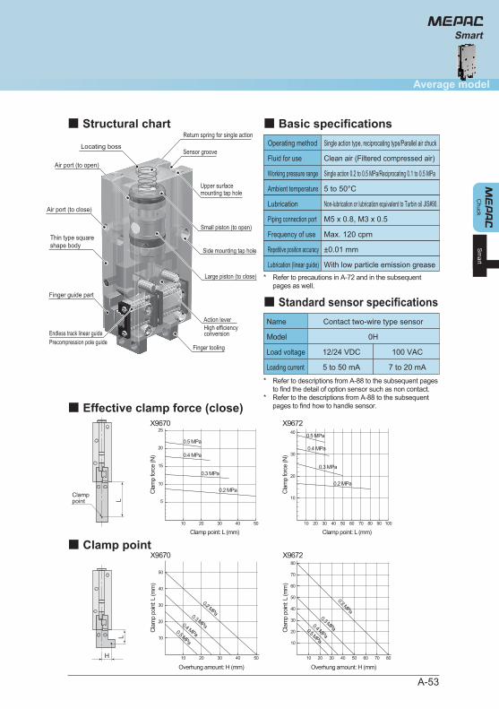
A-53
Chuck
Average model
Sm
art
Smart
Thin type squareshape body
Precompression pole guideEndless track linear guide
Finger tooling
Air port (to open)
Air port (to close)
Finger guide part
Action leverHigh efficiency conversion
Large piston (to close)
Small piston (to open)
Side mounting tap hole
Upper surface mounting tap hole
Return spring for single action
Sensor grooveLocating boss Operating method Single action type, reciprocating type/Parallel air chuck
Clean air (Filtered compressed air)
Single action 0.2 to 0.5 MPa/Reciprocating 0.1 to 0.5 MPa
Max. 120 cpm
±0.01 mm
Fluid for use
Working pressure range
5 to 50°CAmbient temperature
Non-lubrication or lubrication equivalent to Turbin oil JIS#90.Lubrication
Frequency of use
M5 x 0.8, M3 x 0.5Piping connection port
With low particle emission greaseLubrication (linear guide)
Repetitive position accuracy
Name Contact two-wire type sensor
0HModel
12/24 VDCLoad voltage 100 VAC
5 to 50 mALoading current 7 to 20 mA
■ Basic specifications■ Structural chart
■ Standard sensor specifications
*
*
Refer to descriptions from A-88 to the subsequent pages to find the detail of option sensor such as non contact. Refer to the descriptions from A-88 to the subsequent pages to find how to handle sensor.
L
Clamppoint
Clamp point: L (mm)
Cla
mp
forc
e (N
)
10
0.2 MPa
0.3 MPa
0.4 MPa
0.5 MPa
5
10
15
20
25
20 30 40 50
X9670
Clamp point: L (mm)
X9672
Cla
mp
forc
e (N
)
20
10
20
30
40
40 60 80 10010 30 50 70 90
0.2 MPa
0.3 MPa
0.4 MPa
0.5 MPa
L
H
Overhung amount: H (mm)
Cla
mp
poin
t: L
(mm
)
10
0.2 MPa0.3 MPa0.4 MPa0.5 MPa10
20 30 40 50
20
30
40
50
X9670
Overhung amount: H (mm)
Cla
mp
poin
t: L
(mm
)
10 20 30 40 50 60 70 80
0.2 MPa
0.3 MPa0.4 MPa0.5 MPa10
20
30
40
50
60
70
80X9672
■ Effective clamp force (close)
■ Clamp point
* Refer to precautions in A-72 and in the subsequent pages as well.
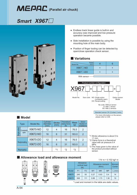
A-54
●
●
●
Endless track linear guide is built-in and accuracy was improved and low pressure operation became possible.
Side installation is possible by using the mounting hole of the main body.
Position of finger tooling can be detected by open/close operation check sensor.
X967 - -Model No. Size code Option sensor
ModelNO: Single action (constantly open)DO: Reciprocating
-
No code: Without sensor S: With 1 sensor SS: With 2 sensors
Standard sensor 0H (Contact 2-wire)
For more information on the sensor,please refer to A-88.
4 6
X967□-NO × ×
X967□-DO × ×
Model No.Stroke
(mm)
With sensor
(Parallel air chuck)
Smart X967□
■ Variations
*1 Stroke allowance is about 0 to +1 mm.
*2 Clamp force is a theoretical value with air pressure 0.4 MPa.
*3 The mass given is the value of the product provided without sensor.
X9670-DO
X9672-DO
16
31
76.5
183.0
*2*1 *3
X9670-NO
X9672-NO
16
31
4
6
4
6
76.5
183.0
Model No.Type
Remarks
Reciprocating
Stroke(mm)
12
16
12
16
Cylinderdiameter
(mm)Mass
(g)
2
2
2
2
SensorNumber of
installations
Theoreticalclamp force
(N)
■ Model
Constantlyopen
Single
actio
n
F1F2 MY MR
MP
L
Allowancevertical load
(N)
Allowance moment(N•m)
Model F1 F2 MY MR MP
245 55 0.27 0.63 0.4
568 111 0.88 1.73 1.36
X9670
X9672
L (mm)
14
19
MomentCenter
1 N・m = 0.102 kgf・m
* Load and moment in the table are static values.
■ Allowance load and allowance moment
Product number configuration
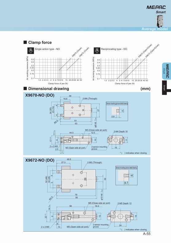
X9672-NO (DO)
9.7
2-M5 Depth 12
2-sensor mounting grooveM5 (Open side air port)2 x 2-M3
M5 (Close side air port)
2-M5 (Through)
614
24
1322
148
104
16.356
26
R0.5
39φ1
0 h6
52 (4
6)34
(28)
55
8078
49.527.3
Sensor mounting groove detail drawing
0 -0.0
09
0 -0.0
5
±0.1
A-55
Chuck
Average model
Sm
art
Smart
Reciprocating type - DOSingle action type - NO
Clamp force of jaw (N)
Air
wor
king
pre
ssur
e (M
Pa)
Clamp force of jaw (N)
Air
wor
king
pre
ssur
e (M
Pa) X96
70 (C
lose)
X9672
(Clos
e)
0.1
0.15
0.20.25
0.3
0.40.5
1.5 2 2.5 3 4 5 6 7 8 910 15 20 2530 40 500.1
1.5 2 2.5 3 4 5 6 7 8 910 15 20 25 30 40 50
0.15
0.20.25
0.3
0.40.5
X9670
(Ope
n/Clos
e)
X9672
(Ope
n/Clos
e)■ Clamp force
■ Dimensional drawing (mm)X9670-NO (DO)
Sensor mounting groove detail drawing
* ( ) indicates when closing.
* ( ) indicates when closing.
5.9
2-sensor mountinggroove
2-M4 Depth 10M3 (Close side air port)
M3 (Open side air port)2 x 2-M3
34 (3
0)23
(19)
2-M4 (Through)
0 -0.0
09
0 -0.0
5
±0.0
5
φ8 h
6
6
11
16
18
1017
116
72.5
12.544.5
R0.5
44
27
6361
3919.8
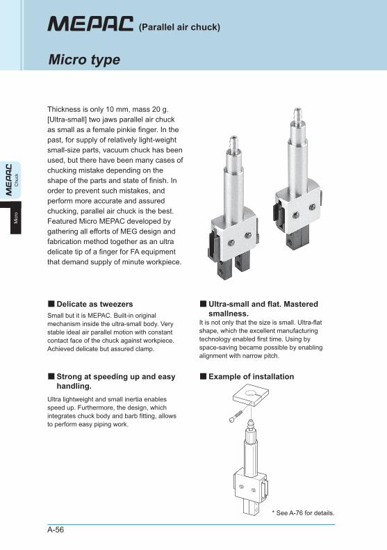
Micro type
A-56
Thickness is only 10 mm, mass 20 g. [Ultra-small] two jaws parallel air chuck as small as a female pinkie finger. In the past, for supply of relatively light-weight small-size parts, vacuum chuck has been used, but there have been many cases of chucking mistake depending on the shape of the parts and state of finish. In order to prevent such mistakes, and perform more accurate and assured chucking, parallel air chuck is the best. Featured Micro MEPAC developed by gathering all efforts of MEG design and fabrication method together as an ultra delicate tip of a finger for FA equipment that demand supply of minute workpiece.
Small but it is MEPAC. Built-in original mechanism inside the ultra-small body. Very stable ideal air parallel motion with constant contact face of the chuck against workpiece. Achieved delicate but assured clamp.
Ultra lightweight and small inertia enables speed up. Furthermore, the design, which integrates chuck body and barb fitting, allows to perform easy piping work.
It is not only that the size is small. Ultra-flat shape, which the excellent manufacturing technology enabled first time. Using by space-saving became possible by enabling alignment with narrow pitch.
(Parallel air chuck)
■Delicate as tweezers ■Ultra-small and flat. Mastered smallness.
■Example of installation■Strong at speeding up and easy handling.
Chu
ckM
icro
* See A-76 for details.
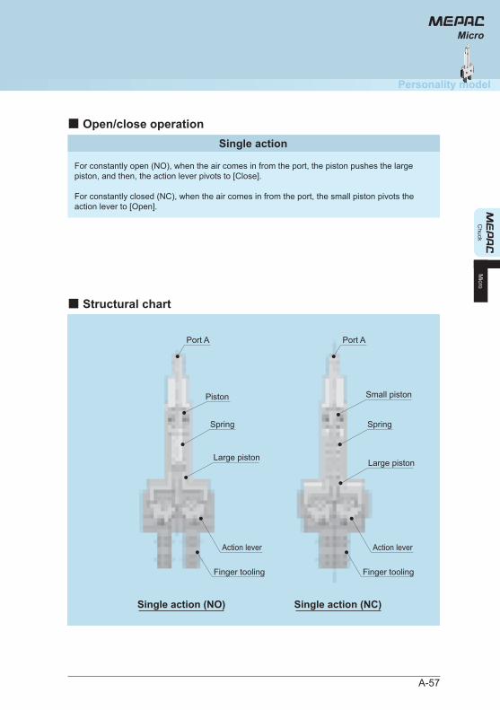
A-57
■ Open/close operationSingle action
For constantly open (NO), when the air comes in from the port, the piston pushes the large piston, and then, the action lever pivots to [Close].
For constantly closed (NC), when the air comes in from the port, the small piston pivots the action lever to [Open].
Chuck
Personality model
Micro
Micro
■ Structural chart
Port A Port A
Spring Spring
Large piston Large piston
Small pistonPiston
Action lever Action lever
Finger tooling Finger tooling
Single action (NO) Single action (NC)
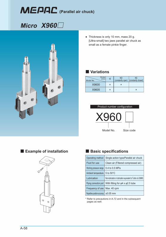
A-58
● Thickness is only 10 mm, mass 20 g. [Ultra-small] two jaws parallel air chuck as small as a female pinkie finger.
Operating method Single action type/Parallel air chuck
Clean air (Filtered compressed air)
0.4 to 0.5 MPa
Max. 40 cpm
±0.05 mm
Fluid for use
Working pressure range
5 to 50°CAmbient temperature
Non-lubrication or lubrication equivalent to Turbin oil JIS#90.Lubrication
Frequency of use
With fitting for φ4 x φ2.5 tubePiping connection port
Repetitive position accuracy
X960Model No. Size code
4 NO(constantly open)
X9600 × ×
X9605 ×
NC(constantly closed)
×
Model No.
Stroke(mm)
(Parallel air chuck)
Micro X960□
■ Basic specifications■ Example of installation
■ Variations
* Refer to precautions in A-72 and in the subsequent pages as well.
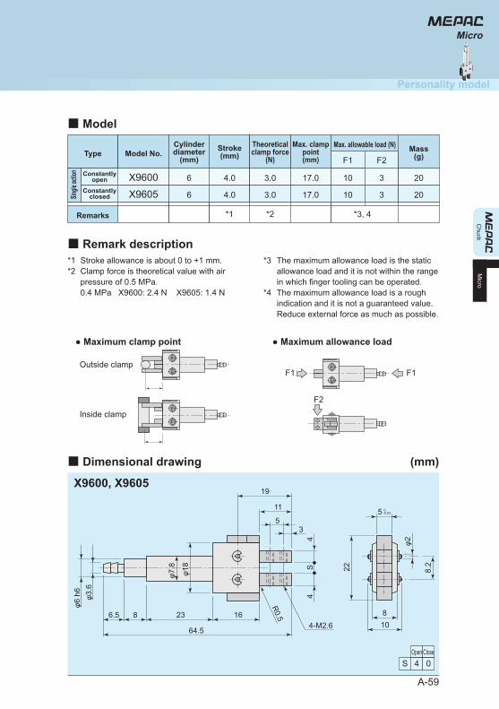
Chuck
Personality model
Micro
R0.5
φ6 h
6φ3
.6
4S
4
φ7.8
φ18
4-M2.664.5
6.5 8 23 16
19
22 8.2
φ2
11
108
55
3
■ Dimensional drawing (mm)
X9600, X9605
Open Close4S 0
0-0.03
A-59
*1*2
Stroke allowance is about 0 to +1 mm. Clamp force is theoretical value with air pressure of 0.5 MPa. 0.4 MPa X9600: 2.4 N X9605: 1.4 N
*3
*4
The maximum allowance load is the static allowance load and it is not within the range in which finger tooling can be operated. The maximum allowance load is a rough indication and it is not a guaranteed value. Reduce external force as much as possible.
X9600 4.0 3.0 17.0 10 3 20
*2*1
F1 F2
*3, 4
X9605 4.0 3.0 17.0 10 3 20
● Maximum clamp point ● Maximum allowance load
F1
F2
F1Outside clamp
Inside clamp
Micro
Model No.TypeMax. allowable load (N)Stroke
(mm)
6
6
Cylinderdiameter
(mm)Mass
(g)Max. clamp
point(mm)
Theoreticalclamp force
(N)
■ Model
■ Remark description
Constantlyopen
ConstantlyclosedSin
gle ac
tion
Remarks
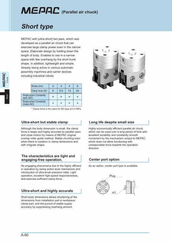
A-60
MEPAC with [ultra-short] two jaws, which was developed as a parallel air chuck that can exercise large clamp power even in the narrow space. Elaborate design by holding down the length of body. Enables to use in a narrow space with few overhang by the short trunk shape. In addition, lightweight and simple. Already being active in various automatic assembly machines and carrier devices including industrial robots.
Chu
ckS
hort
(Parallel air chuck)
Short type
Although the body dimension is small, the clamp force is larger and highly accurate by parallel open and close motion by means of MEPAC original overlap roller guide method. Stable chucking even when there is variation in clamp dimensions and with irregular shape.
Ultra-short but stable clamp
No engaging phenomena due to the highly efficient in operation by swing action lever mechanism and introduction of ultra-small precision roller. Light operation, excellent high-speed responsiveness, and exercise sufficient clamp force.
The characteristics are light and engaging-free operation.
Short body dimensions allows shortening of the dimensions from installation part to workpiece clamp part, and the pursuit of stable supply accuracy by suppressing overhang amount.
Ultra-short and highly accurate
Highly economically efficient parallel air chuck, which can be used over a long period of time with excellent durability and constantly smooth movement by the mechanism unique to MEPAC, which does not allow functioning with unreasonable force towards the operation direction.
Long life despite small size
As an option, center port type is available.
Center port option
13
Single action Constantlyopen (NO)
Stroke (mm)
Clamp force (N)*
×
24
×
* Clamp force is the value for NO type at 0.4 MPa.
Single action Constantlyclosed (NC) × ×
5
×
8.5
4 64 4
×
× ×
m1
Plug
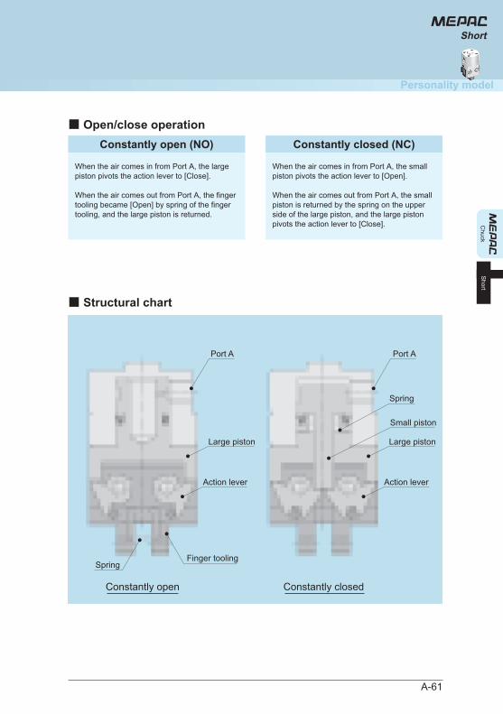
A-61
Chuck
Personality model
Short
Short
■ Open/close operationConstantly open (NO)
When the air comes in from Port A, the large piston pivots the action lever to [Close].
When the air comes out from Port A, the finger tooling became [Open] by spring of the finger tooling, and the large piston is returned.
Constantly closed (NC)
When the air comes in from Port A, the small piston pivots the action lever to [Open].
When the air comes out from Port A, the small piston is returned by the spring on the upper side of the large piston, and the large piston pivots the action lever to [Close].
■ Structural chart
Constantly closedConstantly open
Port A
Action lever
Port A
Action lever
Large piston
Small piston
Spring
Finger toolingSpring
Large piston
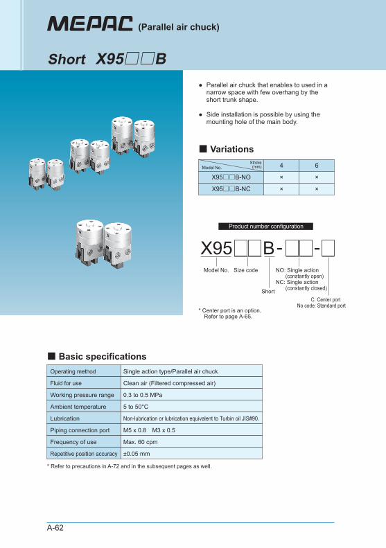
A-62
●
●
Parallel air chuck that enables to used in a narrow space with few overhang by the short trunk shape.
Side installation is possible by using the mounting hole of the main body.
Operating method Single action type/Parallel air chuck
Clean air (Filtered compressed air)
0.3 to 0.5 MPa
Max. 60 cpm
±0.05 mm
Fluid for use
Working pressure range
5 to 50°CAmbient temperature
Non-lubrication or lubrication equivalent to Turbin oil JIS#90.Lubrication
Frequency of use
M5 x 0.8 M3 x 0.5Piping connection port
Repetitive position accuracy
X95 B-Model No. Size code
Short
NO: Single action (constantly open)NC: Single action (constantly closed)
-
C: Center portNo code: Standard port
* Center port is an option. Refer to page A-65.
4 6
X95□□B-NO × ×
X95□□B-NC × ×
Model No.Stroke
(mm)
(Parallel air chuck)
Short X95□□B
■ Basic specifications
■ Variations
* Refer to precautions in A-72 and in the subsequent pages as well.
Product number configuration
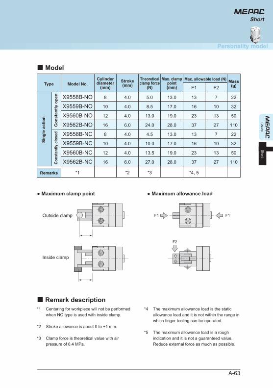
A-63
*1
*2
*3
Centering for workpiece will not be performed when NO type is used with inside clamp.
Stroke allowance is about 0 to +1 mm.
Clamp force is theoretical value with air pressure of 0.4 MPa.
*4
*5
The maximum allowance load is the static allowance load and it is not within the range in which finger tooling can be operated.
The maximum allowance load is a rough indication and it is not a guaranteed value. Reduce external force as much as possible.
X9558B-NO
X9559B-NO
4.0
4.0
5.0
8.5
13.0
17.0
13
16
7
10
22
32
X9560B-NO 4.0 13.0 19.0 23 13
X9562B-NO 6.0 24.0 28.0 37 27
*1 *3*2 *4, 5
50
110
X9558B-NC
X9559B-NC
4.0
4.0
4.5
10.0
13.0
17.0
13
16
7
10
22
32
X9560B-NC 4.0 13.5 19.0 23 13
X9562B-NC 6.0 27.0 28.0 37 27
50
110
● Maximum clamp point ● Maximum allowance load
Outside clamp
Inside clamp
F1 F1
F2
F1 F2Type Model No.
Max. allowable load (N)Stroke(mm)
8
10
12
16
8
10
12
16
Cylinderdiameter
(mm)Mass
(g)Max. clamp
point(mm)
Theoreticalclamp force
(N)
■ Model
■ Remark description
Sing
le a
ctio
n
Con
stan
tly o
pen
Cons
tant
ly c
lose
d
Remarks
Chuck
Personality model
Short
Short
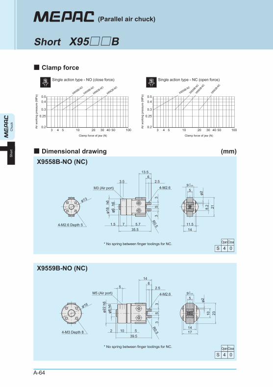
A-64
0.2
0.25
0.3
0.40.5
3 4 5 10 20 30 40 50 100Clamp force of jaw (N)
Air
wor
king
pre
ssur
e (M
Pa)
X9559
B-NC
X9558B-NC
X9560
B-NC
X9562
B-NC
Single action type - NC (open force)
0.2
0.25
0.3
0.40.5
3 4 5 10 20 30 40 50 100Clamp force of jaw (N)
Air
wor
king
pre
ssur
e (M
Pa)
X9558B-NO
X9559B-NO
X9560B-NO
X9562B-NO
Single action type - NO (close force)
■ Clamp force
■ Dimensional drawing (mm)
Chu
ckS
hort
(Parallel air chuck)
Short X95□□B
X9558B-NO (NC)
X9559B-NO (NC)
* No spring between finger toolings for NC.
M5 (Air port)
φ16
2310φ2
95
1714
14
2.5
φ22
h6φ8
h6
R0.5
3S
3
4-M3 Depth 8
4-M2.6
65
39.55102
* No spring between finger toolings for NC.
M3 (Air port)
218.2
φ2φ13
R0.5
13.5
2.5
3S
3
h6φ1
8h6
φ6
4-M2.69
5
1411.54-M2.6 Depth 5
3.56
35.55.771.5
Open Close4S 0
Open Close4S 0
0-0.05
0-0.03
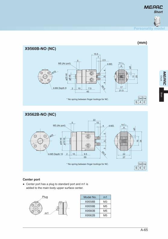
A-65
X9560B-NO (NC)
X9562B-NO (NC)
Chuck
Personality model
Short
Short
* No spring between finger toolings for NC.
φ18
φ3
2511
116
21.517
R0.55
φ25
h6φ8
h6
4S
4
457.51024-M4 Depth 8
4-M3
15.5
2.57
M5 (Air port)
* No spring between finger toolings for NC.
3416φ3
148
2722
φ25
R0.5
5S
5
22
45
φ34
h6φ1
0 h6
559.51024-M5 Depth 10
4-M310
M5 (Air port)
Open Close4S 0
Open Close6S 0
0-0.03
0-0.03
m1
● Center port has a plug to standard port and m1 is added to the main body upper surface center.
Center port
Plug Model No.X9558B
m1M3
X9559B M5X9560B M5X9562B M5
(mm)
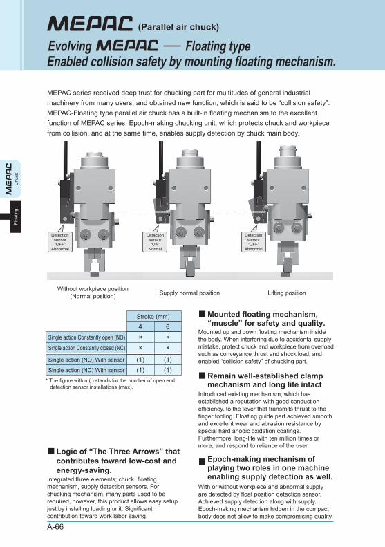
A-66
MEPAC series received deep trust for chucking part for multitudes of general industrial machinery from many users, and obtained new function, which is said to be “collision safety”. MEPAC-Floating type parallel air chuck has a built-in floating mechanism to the excellent function of MEPAC series. Epoch-making chucking unit, which protects chuck and workpiece from collision, and at the same time, enables supply detection by chuck main body.
Mounted up and down floating mechanism inside the body. When interfering due to accidental supply mistake, protect chuck and workpiece from overload such as conveyance thrust and shock load, and enabled “collision safety” of chucking part.
Introduced existing mechanism, which has established a reputation with good conduction efficiency, to the lever that transmits thrust to the finger tooling. Floating guide part achieved smooth and excellent wear and abrasion resistance by special hard anodic oxidation coatings. Furthermore, long-life with ten million times or more, and respond to reliance of the user.
With or without workpiece and abnormal supply are detected by float position detection sensor. Achieved supply detection along with supply. Epoch-making mechanism hidden in the compact body does not allow to make compromising quality.
Integrated three elements; chuck, floating mechanism, supply detection sensors. For chucking mechanism, many parts used to be required, however, this product allows easy setup just by installing loading unit. Significant contribution toward work labor saving.
Detectionsensor“OFF”
Abnormal
Detectionsensor“ON”
Normal
Detectionsensor“OFF”
Abnormal
Without workpiece position(Normal position) Supply normal position Lifting position
Chu
ckFl
oatin
g
(Parallel air chuck)
EvolvingEnabled collision safety by mounting floating mechanism.
Floating type
■Epoch-making mechanism of playing two roles in one machine enabling supply detection as well.
■Mounted floating mechanism, “muscle” for safety and quality.
■Logic of “The Three Arrows” that contributes toward low-cost and energy-saving.
■Remain well-established clamp mechanism and long life intact
4Single action Constantly open (NO)
Stroke (mm)
×6×
Single action (NO) With sensor
Single action (NC) With sensor
* The figure within ( ) stands for the number of open end detection sensor installations (max).
(1) (1)(1)
Single action Constantly closed (NC) × ×
(1)
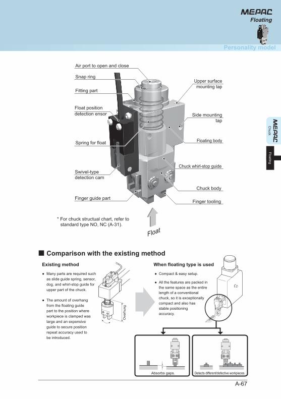
A-67
Chuck
Personality model
Floating
Floating
Finger guide part
Swivel-type detection cam
Float
Finger tooling
Chuck body
Spring for float
Chuck whirl-stop guide
Upper surfacemounting tap
Side mountingtap
Floating body
Fitting part
Air port to open and close
Snap ring
Existing method When floating type is used
Many parts are required such as slide guide spring, sensor, dog, and whirl-stop guide for upper part of the chuck.
The amount of overhang from the floating guide part to the position where workpiece is clamped was large and an expensive guide to secure position repeat accuracy used to be introduced.
●
●
Compact & easy setup.
All the features are packed in the same space as the entire length of a conventional chuck, so it is exceptionally compact and also has stable positioning accuracy.
●
●
Ove
rhun
g
■ Comparison with the existing method
Absorbs gaps. Detects different/defective workpieces.
* For chuck structual chart, refer to standard type NO, NC (A-31).
Float position detection ensor
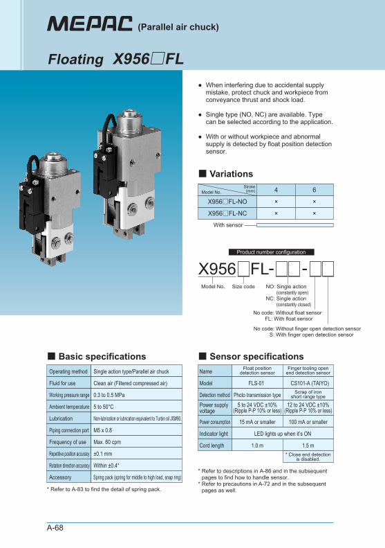
A-68
●
●
●
When interfering due to accidental supply mistake, protect chuck and workpiece from conveyance thrust and shock load.
Single type (NO, NC) are available. Type can be selected according to the application.
With or without workpiece and abnormal supply is detected by float position detection sensor.
Operating method Single action type/Parallel air chuck
Clean air (Filtered compressed air)
0.3 to 0.5 MPa
Max. 60 cpm
±0.1 mm
Fluid for use
Working pressure range
5 to 50°CAmbient temperature
Non-lubrication or lubrication equivalent to Turbin oil JIS#90.Lubrication
Frequency of use
M5 x 0.8Piping connection port
Repetitive position accuracy
Within ±0.4°Rotation direction accuracy
Spring pack (spring for middle to high load, snap ring)Accessory
X956 FL -Model No. Size code
No code: Without finger open detection sensor S: With finger open detection sensor
No code: Without float sensor FL: With float sensor
-NO: Single action (constantly open)NC: Single action (constantly closed)
With sensor
4 6
X956□FL-NO × ×
X956□FL-NC × ×
Name Float positiondetection sensor
5 to 24 VDC ±10%(Ripple P-P 10% or less)
FLS-01
1.0 m
Power supply voltage
Model
Photo transmission typeDetection method
15 mA or smallerPower consumption
Finger tooling openend detection sensor
12 to 24 VDC ±10%(Ripple P-P 10% or less)
CS101-A (TAIYO)
1.5 m
Scrap of ironshort range type
100 mA or smaller
LED lights up when it’s ONIndicator light
Cord length* Close end detection
is disabled.
* Refer to A-83 to find the detail of spring pack.
* Refer to descriptions in A-86 and in the subsequent pages to find how to handle sensor.
* Refer to precautions in A-72 and in the subsequent pages as well.
Model No.Stroke
(mm)
(Parallel air chuck)
Floating X956□FL
■ Basic specifications ■ Sensor specifications
■ Variations
Product number configuration
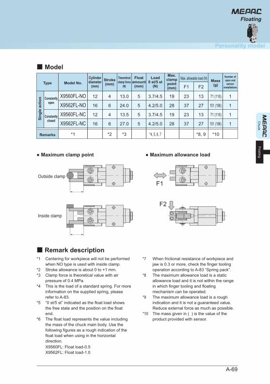
A-69
*1
*2*3
*4
*5
*6
Centering for workpiece will not be performed when NO type is used with inside clamp. Stroke allowance is about 0 to +1 mm. Clamp force is theoretical value with air pressure of 0.4 MPa. This is the load of a standard spring. For more information on the supplied spring, please refer to A-83. “0 st/5 st” indicated as the float load shows the free state and the position on the float end. The float load represents the value including the mass of the chuck main body. Use the following figures as a rough indication of the float load when using in the horizontal direction.X9560FL: Float load-0.5X9562FL: Float load-1.0
*7
*8
*9
*10
When frictional resistance of workpiece and jaw is 0.3 or more, check the finger tooling operation according to A-83 “Spring pack”. The maximum allowance load is a static allowance load and it is not within the range in which finger tooling and floating mechanism can be operated. The maximum allowance load is a rough indication and it is not a guaranteed value. Reduce external force as much as possible. The mass given in ( ) is the value of the product provided with sensor.
X9560FL-NO
X9562FL-NO
13.0
24.0
19
28
23
37
13
27
71 (116)
151 (196)
*1
F1 F2
*3*2 *8, 9
X9560FL-NC
X9562FL-NC
13.5
27.0
5
5
5
5
3.7/4.5
4.2/5.0
*4, 5, 6, 7 *10
3.7/4.5
4.2/5.0
19
28
23
37
13
27
71 (116)
151 (196)
● Maximum clamp point ● Maximum allowance load
Outside clamp
Inside clamp
F1
F2
4
6
4
6
Model No.TypeMax. allowable load (N)Stroke
(mm)
12
16
12
16
Cylinderdiameter
(mm)Mass
(g)
Max.clamppoint(mm)
1
1
1
1
Number ofopen end
sensorinstallations
Floatamount
(mm)
Theoreticalclamp force
(N)
Load0 st/5 st
(N)
■ Model
■ Remark description
Constantlyopen
Constantlyclosed
Remarks
Sing
le a
ctio
n
Chuck
Personality model
Floating
Floating
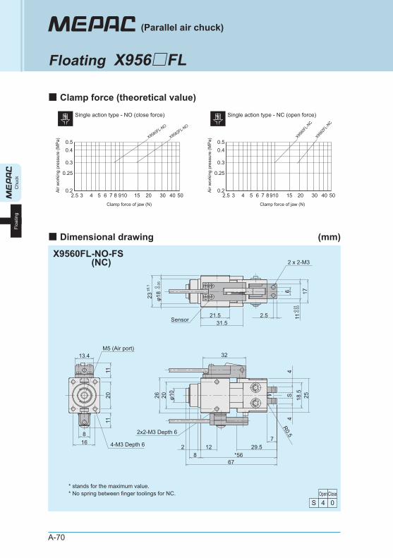
Chu
ckFl
oatin
g
A-70
Single action type - NC (open force)Single action type - NO (close force)
0.2
0.25
0.3
0.40.5
32.5 4 5 6 7 8910 15 20 30 40 50Clamp force of jaw (N)
Air
wor
king
pre
ssur
e (M
Pa)
X9560
FL-N
CX95
62FL
-NC
0.2
0.25
0.3
0.40.5
32.5 4 5 6 7 8 910 15 20 30 40 50Clamp force of jaw (N)
Air
wor
king
pre
ssur
e (M
Pa)
X9560FL-NO
X9562FL-NO
(Parallel air chuck)
Floating X956□FL
■ Clamp force (theoretical value)
■ Dimensional drawing (mm)
X9560FL-NO-FS(NC)
Open Close4S 0
* stands for the maximum value. * No spring between finger toolings for NC.
R0.5
168
13.4
20
31.521.5
23 φ18 17
11
6
26 20 φ10
4S
4
2518.5
122
67*568
32
2.5
2 x 2-M3
2x2-M3 Depth 6
4-M3 Depth 6
1111
Sensor
29.57
M5 (Air port)
±0.1 0 -0.0
5
-0.0
1-0
.03
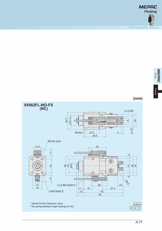
A-71
Chuck
Personality model
Floating
Floating
X9562FL-NO-FS(NC)
* stands for the maximum value. * No spring between finger toolings for NC.
24
188
13.4
±0.1
30φ1
8 2214
8
38.527.5
R0.5
34265
S5
35 24 φ10
32
83*7010
16228
4
4-M4 Depth 8
M5 (Air port)
1111
Sensor
2 x 2-M3
2 x 2-M4 Depth 837.5
10
0 -0.0
5
-0.0
1-0
.03
Open Close6S 0
(mm)
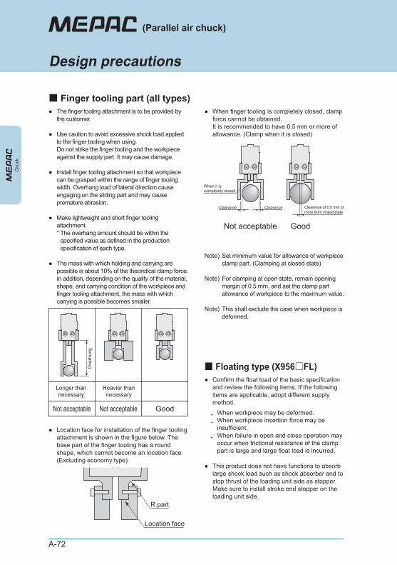
A-72
●
●
●
●
●
The finger tooling attachment is to be provided by the customer.
Use caution to avoid excessive shock load applied to the finger tooling when using. Do not strike the finger tooling and the workpiece against the supply part. It may cause damage.
Install finger tooling attachment so that workpiece can be grasped within the range of finger tooling width. Overhang load of lateral direction cause engaging on the sliding part and may cause premature abrasion.
Make lightweight and short finger tooling attachment. * The overhang amount should be within the
specified value as defined in the production specification of each type.
The mass with which holding and carrying are possible is about 10% of the theoretical clamp force. In addition, depending on the quality of the material, shape, and carrying condition of the workpiece and finger tooling attachment, the mass with which carrying is possible becomes smaller.
● When finger tooling is completely closed, clamp force cannot be obtained. It is recommended to have 0.5 mm or more of allowance. (Clamp when it is closed)
Note)
Note)
Note)
Set minimum value for allowance of workpiece clamp part. (Clamping at closed state)
For clamping at open state, remain opening margin of 0.5 mm, and set the clamp part allowance of workpiece to the maximum value.
This shall exclude the case when workpiece is deformed.
● Location face for installation of the finger tooling attachment is shown in the figure below. The base part of the finger tooling has a round shape, which cannot become an location face. (Excluding economy type)
Longer thannecessary
Heavier thannecessary
Not acceptable GoodNot acceptable
Ove
rhun
g
R part
Location face
ClearanceClearance
When it is completely closed
Not acceptable Good
Chu
ck
(Parallel air chuck)
Design precautions
■ Finger tooling part (all types)
● Confirm the float load of the basic specification and review the following items. If the following items are applicable, adopt different supply method.
・・
・
When workpiece may be deformed. When workpiece insertion force may be insufficient. When failure in open and close operation may occur when frictional resistance of the clamp part is large and large float load is incurred.
■ Floating type (X956□FL)
● This product does not have functions to absorb large shock load such as shock absorber and to stop thrust of the loading unit side as stopper. Make sure to install stroke end stopper on the loading unit side.
Clearance of 0.5 mm or more from closed state
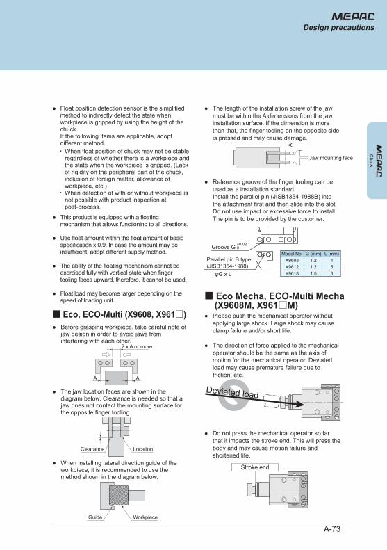
A-73
Chuck
● Float position detection sensor is the simplified method to indirectly detect the state when workpiece is gripped by using the height of the chuck. If the following items are applicable, adopt different method.・
・
When float position of chuck may not be stable regardless of whether there is a workpiece and the state when the workpiece is gripped. (Lack of rigidity on the peripheral part of the chuck, inclusion of foreign matter, allowance of workpiece, etc.)When detection of with or without workpiece is not possible with product inspection at post-process.
●
●
●
●
This product is equipped with a floating mechanism that allows functioning to all directions.
Use float amount within the float amount of basic specification x 0.9. In case the amount may be insufficient, adopt different supply method.
The ability of the floating mechanism cannot be exercised fully with vertical state when finger tooling faces upward, therefore, it cannot be used.
Float load may become larger depending on the speed of loading unit.
Design precautions
■ Eco Mecha, ECO-Multi Mecha (X9608M, X961□M)●
●
Please push the mechanical operator without applying large shock. Large shock may cause clamp failure and/or short life.
The direction of force applied to the mechanical operator should be the same as the axis of motion for the mechanical operator. Deviated load may cause premature failure due to friction, etc.
● When installing lateral direction guide of the workpiece, it is recommended to use the method shown in the diagram below.
● Do not press the mechanical operator so far that it impacts the stroke end. This will press the body and may cause motion failure and shortened life.
■ Eco, ECO-Multi (X9608, X961□)● Before grasping workpiece, take careful note of
jaw design in order to avoid jaws from interfering with each other.
● The jaw location faces are shown in the diagram below. Clearance is needed so that a jaw does not contact the mounting surface for the opposite finger tooling.
2 x A or more
A A
A
Clearance Location
WorkpieceGuide
● The length of the installation screw of the jaw must be within the A dimensions from the jaw installation surface. If the dimension is more than that, the finger tooling on the opposite side is pressed and may cause damage.
● Reference groove of the finger tooling can be used as a installation standard. Install the parallel pin (JISB1354-1988B) into the attachment first and then slide into the slot. Do not use impact or excessive force to install. The pin is to be provided by the customer.
Jaw mounting face
Deviated load
Stroke end
Parallel pin B type(JISB1354-1988)
Groove G
φG x L
+0.020
Model No. G (mm) L (mm)X9608 1.2 4X9612 1.2 5X9618 1.5 8
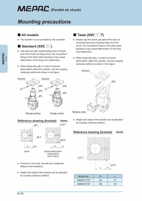
A-74
●
●
Please use the shank part φda of the body or mounting face and mounting holes to fix the chuck. Do not perform fixing on the other parts because it may cause deformation of the body and malfunction.
When fixing with φda, in order to prevent deformation within the cylinder, use the coupling clamping method as shown in the figure.
● Height and angle of the bracket can be adjusted by coupling clamping method.
Reference drawing (bracket)
φD1H8
φ6.5L1 6
φda
Bracket
Retainer plate
Model No.X9563T/73TX9564T/74T
D1
2226
L1
1719
Chu
ck
(Parallel air chuck)
Mounting precautions
■ All models● The bracket is to be provided by the customer.
■ Standard (X95□□)●
●
Use φda and φdb (reciprocating only) of shank part of the body for fixing chuck. Do not perform fixing on the other parts because it may cause deformation of the body and malfunction.
When fixing with φdb, in order to prevent deformation within the cylinder, use the coupling clamping method as shown in the figure.
●
●
If sensor is not used, use φdc as a supporter (fitting of anti-vibration).
Height and angle of the bracket can be adjusted by coupling clamping method.
φda
Bracket
φdc
φda
φdb
Bracket
φdc
Reciprocating Single action
Reference drawing (bracket) (mm)φ8H8
φ4.5
8 4.5
φ10H8
10 5
X9558 X9559/X9560/X9561X9562/X9570X9571/X9572
φ5.5
■ Taste (X95□□T)
(mm)
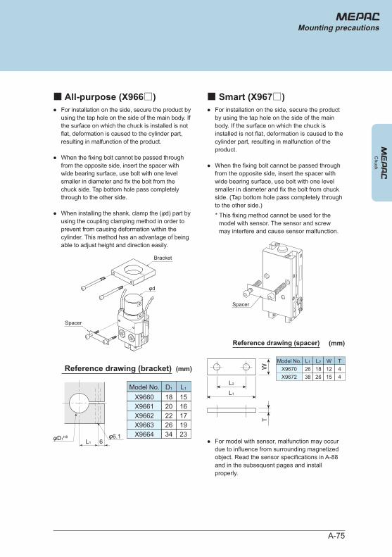
A-75
Chuck
Mounting precautions
■ All-purpose (X966□)●
●
●
For installation on the side, secure the product by using the tap hole on the side of the main body. If the surface on which the chuck is installed is not flat, deformation is caused to the cylinder part, resulting in malfunction of the product.
When the fixing bolt cannot be passed through from the opposite side, insert the spacer with wide bearing surface, use bolt with one level smaller in diameter and fix the bolt from the chuck side. Tap bottom hole pass completely through to the other side.
When installing the shank, clamp the (φd) part by using the coupling clamping method in order to prevent from causing deformation within the cylinder. This method has an advantage of being able to adjust height and direction easily.
Reference drawing (bracket)
φD1H8 φ6.1L1 6
Model No.X9660X9661
D1
1820
L1
1516
X9662X9663
2226
1719
X9664 34 23
Bracket
Spacer
φd
■ Smart (X967□)●
●
For installation on the side, secure the product by using the tap hole on the side of the main body. If the surface on which the chuck is installed is not flat, deformation is caused to the cylinder part, resulting in malfunction of the product.
When the fixing bolt cannot be passed through from the opposite side, insert the spacer with wide bearing surface, use bolt with one level smaller in diameter and fix the bolt from chuck side. (Tap bottom hole pass completely through to the other side.)* This fixing method cannot be used for the
model with sensor. The sensor and screw may interfere and cause sensor malfunction.
● For model with sensor, malfunction may occur due to influence from surrounding magnetized object. Read the sensor specifications in A-88 and in the subsequent pages and install properly.
Spacer
L2
WT
L1
Model No. L1 L2 W TX9670 26 18 12 4X9672 38 26 15 4
Reference drawing (spacer)
(mm)
(mm)
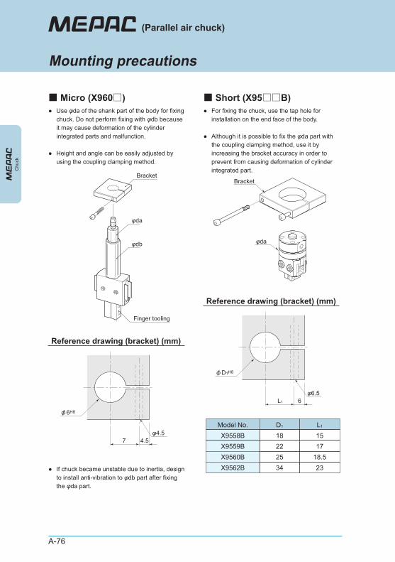
A-76
Chu
ck
(Parallel air chuck)
Mounting precautions
■ Micro (X960□)●
●
Use φda of the shank part of the body for fixing chuck. Do not perform fixing with φdb because it may cause deformation of the cylinder integrated parts and malfunction.
Height and angle can be easily adjusted by using the coupling clamping method.
● If chuck became unstable due to inertia, design to install anti-vibration to φdb part after fixing the φda part.
Reference drawing (bracket) (mm)
φ4.57 4.5
Bracket
φda
φdb
Finger tooling
■ Short (X95□□B)●
●
For fixing the chuck, use the tap hole for installation on the end face of the body.
Although it is possible to fix the φda part with the coupling clamping method, use it by increasing the bracket accuracy in order to prevent from causing deformation of cylinder integrated part.
Reference drawing (bracket) (mm)
φ6.5L1 6
Model No.X9558BX9559B
D1
1822
L1
1517
X9560BX9562B
2534
18.523
Bracket
φda
6H8
D1H8
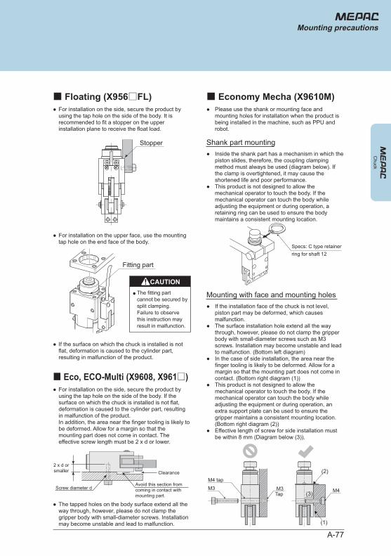
A-77
Chuck
Mounting precautions
■ Floating (X956□FL)● For installation on the side, secure the product by
using the tap hole on the side of the body. It is recommended to fit a stopper on the upper installation plane to receive the float load.
● For installation on the upper face, use the mounting tap hole on the end face of the body.
● If the surface on which the chuck is installed is not flat, deformation is caused to the cylinder part, resulting in malfunction of the product.
Stopper
Fitting part
CAUTION● The fitting part
cannot be secured by split clamping. Failure to observe this instruction may result in malfunction.
■ Economy Mecha (X9610M)● Please use the shank or mounting face and
mounting holes for installation when the product is being installed in the machine, such as PPU and robot.
●
●
Inside the shank part has a mechanism in which the piston slides, therefore, the coupling clamping method must always be used (diagram below). If the clamp is overtightened, it may cause the shortened life and poor performance. This product is not designed to allow the mechanical operator to touch the body. If the mechanical operator can touch the body while adjusting the equipment or during operation, a retaining ring can be used to ensure the body maintains a consistent mounting location.
● The tapped holes on the body surface extend all the way through, however, please do not clamp the gripper body with small-diameter screws. Installation may become unstable and lead to malfunction.
■ Eco, ECO-Multi (X9608, X961□)● For installation on the side, secure the product by
using the tap hole on the side of the body. If the surface on which the chuck is installed is not flat, deformation is caused to the cylinder part, resulting in malfunction of the product. In addition, the area near the finger tooling is likely to be deformed. Allow for a margin so that the mounting part does not come in contact. The effective screw length must be 2 x d or lower.
Clearance
Screw diameter d
2 x d orsmaller
Shank part mounting
●
●
●
●
●
If the installation face of the chuck is not level, piston part may be deformed, which causes malfunction. The surface installation hole extend all the way through, however, please do not clamp the gripper body with small-diameter screws such as M3 screws. Installation may become unstable and lead to malfunction. (Bottom left diagram)In the case of side installation, the area near the finger tooling is likely to be deformed. Allow for a margin so that the mounting part does not come in contact. (Bottom right diagram (1))This product is not designed to allow the mechanical operator to touch the body. If the mechanical operator can touch the body while adjusting the equipment or during operation, an extra support plate can be used to ensure the gripper maintains a consistent mounting location. (Bottom right diagram (2)) Effective length of screw for side installation must be within 8 mm (Diagram below (3)).
Mounting with face and mounting holes
M4 tap
Specs: C type retainer ring for shaft 12
M3 M3Tap
M4
(2)
(3)
(1)
Avoid this section from coming in contact with mounting part.
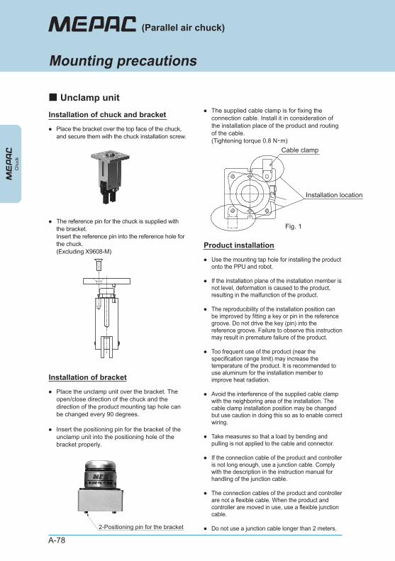
A-78
2-Positioning pin for the bracket
Chu
ck
(Parallel air chuck)
Mounting precautions
■ Unclamp unit
● Place the bracket over the top face of the chuck, and secure them with the chuck installation screw.
● The reference pin for the chuck is supplied with the bracket. Insert the reference pin into the reference hole for the chuck. (Excluding X9608-M)
Cable clamp
Installation location
Installation of chuck and bracket
●
●
Place the unclamp unit over the bracket. The open/close direction of the chuck and the direction of the product mounting tap hole can be changed every 90 degrees.
Insert the positioning pin for the bracket of the unclamp unit into the positioning hole of the bracket properly.
● The supplied cable clamp is for fixing the connection cable. Install it in consideration of the installation place of the product and routing of the cable. (Tightening torque 0.8 N・m)
Installation of bracket
●
●
●
●
●
●
●
●
●
Use the mounting tap hole for installing the product onto the PPU and robot.
If the installation plane of the installation member is not level, deformation is caused to the product, resulting in the malfunction of the product.
The reproducibility of the installation position can be improved by fitting a key or pin in the reference groove. Do not drive the key (pin) into the reference groove. Failure to observe this instruction may result in premature failure of the product.
Too frequent use of the product (near the specification range limit) may increase the temperature of the product. It is recommended to use aluminum for the installation member to improve heat radiation.
Avoid the interference of the supplied cable clamp with the neighboring area of the installation. The cable clamp installation position may be changed but use caution in doing this so as to enable correct wiring.
Take measures so that a load by bending and pulling is not applied to the cable and connector.
If the connection cable of the product and controller is not long enough, use a junction cable. Comply with the description in the instruction manual for handling of the junction cable.
The connection cables of the product and controller are not a flexible cable. When the product and controller are moved in use, use a flexible junction cable.
Do not use a junction cable longer than 2 meters.
Product installation
Fig. 1
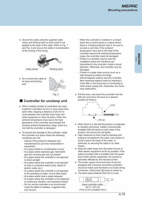
A-79
Chuck
Mounting precautions
● Secure the cable using the supplied cable clamp and binding band so that a load is not applied to the base of the cable. Refer to Fig. 1 and Fig. 2 and secure the cable in consideration of the routing of the wiring.
● When multiple number of controllers are used, install the controllers 20 mm or more away from each other, keeping a distance of 25 mm or more between the controller main body and other equipment or other structure. When the ambient temperature rises due to the heat generation of the controller and exceeds the working ambient temperature range, there is a risk that the controller is damaged.
●
●
●
●
●
When there is a risk that the product is subjected to vibration and shock, install a commercially available DIN rail clamp on both sides of the product, and secure the rail tightly. Take measures so that a load by bending and pulling is not applied to the cable. Use caution to avoid a load to the base of the cable, in particular, by securing the cable or by other means. Keep the cable away from the power source of other electric equipment as far as possible. If the cable is bundled with or installed near the power line of other electric equipment, the product is adversely affected by the induced current. The power supply circuit and input circuit are equipped with a reverse connection protection circuit but make sure that there is no faulty wiring connection. Check that LED lamp is turned on. The bend radius shall be R33 mm or more.
● Pull the lever, and insert the controller into the DIN rail, and return the lever at a desired position for fixing it.
● To prevent the damage to the controller, install the controller at a place where the following conditions are met.・
・・
・
・
・
・・
・
Indoors (This product is designed and manufactured so as to be incorporated in equipment)At a place where no condensation occursAt a place where explosive gas, flammable gas and corrosive gas are not presentAt a place where the controller is not exposed to direct sunlightAt a place where the controller is not exposed to dust or conductive debris (chip, debris of electric cable, etc.)At a place where the controller is not exposed to the sprinkling of water, oil and other liquidAt a place where heat is easily releasedAt a place where the controller is not subjected to continuous vibration, and excessive impactDo not use the controller in an environment under the effect of radiation, magnetic field, and vacuum.
・
・
・
When the controller is installed in a closed place like a control panel or a place where there is a heating element near it, be sure to provide a vent hole. If the ambient temperature rises due to the heat of the controller beyond the working temperature range, the controller could be damaged. If there is a vibration source near the installation place and vibrations are transmitted to the controller, install a shock absorber. Otherwise, the controller may be damaged. If there is a large noise source (such as a high-frequency welder and large electromagnetic switch) near the controller, take measures against noise by inserting a noise filter in the wiring line or connecting to other power supply line. Otherwise, the motor may malfunction.
● Do not bend the cable at its base and binding part.
Fig. 2
Binding bandCable clamp
■ Controller for unclamp unit
DIN rail
Lever
Pull
Upper controller cableφ5.5 x 100 mm
(This is not a shielded wire.)
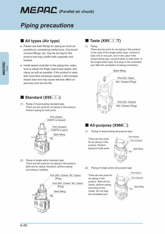
A-80
Chu
ck
(Parallel air chuck)
Piping precautions
● Please use barb fittings for piping as much as possible by considering inertia force. One-touch connect fittings, etc. may be too big for this product and may conflict with supporter and bracket.
(1) Piping of reciprocating standard typeThere are two ports for air piping in this product. Perform piping for both ports.
(2) Piping of single action standard typeThere are two ports for air piping in this product. Both are for clamp, therefore, perform piping according to usability.
● Install speed controller to the piping line, make sure to adjust the finger open/close speed, and clamp as soft as possible. If the product is used with more than necessary speed, it will increase impact load and may cause adverse effect on accuracy and service life.
Barb fitting
Port (NO: Closed NC: Open)(Plug)
Port (NO: Closed NC: Open)(Plug)
Barb fitting
Port (Open)(X9570 is closed)
Port (Closed)(X9570 is open)
■ All types (Air type)
■ Standard (X95□□)
■ Taste (X95□□T)
■ All-purpose (X966□)(1) Piping of reciprocating all-purpose type
There are two ports for air piping in this product. Perform piping for both ports.
(2) Piping of single action all-purpose type
There are two ports for air piping in this product. Both are for clamp, perform piping according to the model. Do not plug the unneeded port.
Barb fitting
Port (Open)
Port (Closed)
Barb fitting
Port (Open)
Port (Closed)
(1) PipingThere are two ports for air piping in this product. In the case of the single-action type, connect a tube only to one port, and in the case of the reciprocating type, connect tubes to both ports. In the single-action type, fit a plug on the unneeded port after the completion of piping connection.
Barb fitting
Port DO: OpenNO: Closed (Plug)
Port DO: ClosedNO: Closed (Plug)
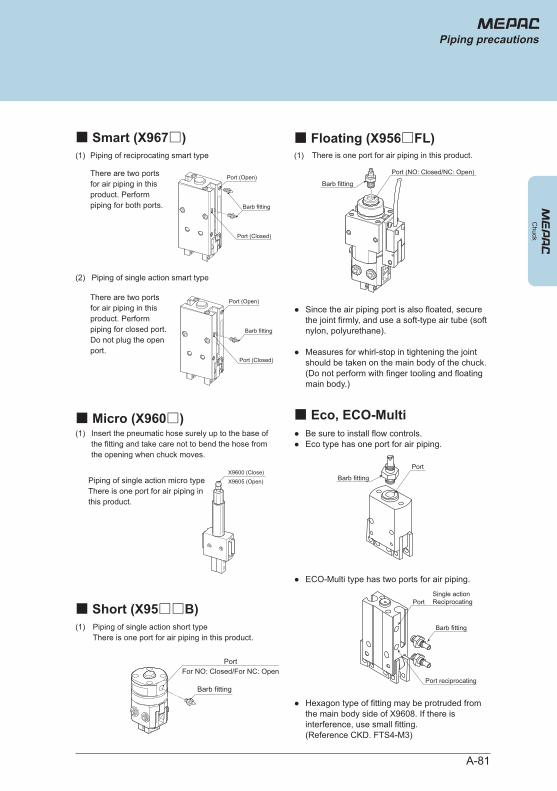
A-81
Chuck
Piping precautions
■ Smart (X967□)(1)
(1)
Piping of reciprocating smart type
There are two ports for air piping in this product. Perform piping for both ports.
There are two ports for air piping in this product. Perform piping for closed port. Do not plug the open port.
(2) Piping of single action smart type
Barb fitting
Port (Open)
Port (Closed)
Barb fitting
Port (Open)
Port (Closed)
■ Micro (X960□)
■ Short (X95□□B)
■ Floating (X956□FL)
■ Eco, ECO-Multi
There is one port for air piping in this product.
●
●
Since the air piping port is also floated, secure the joint firmly, and use a soft-type air tube (soft nylon, polyurethane).
Measures for whirl-stop in tightening the joint should be taken on the main body of the chuck. (Do not perform with finger tooling and floating main body.)
● Hexagon type of fitting may be protruded from the main body side of X9608. If there is interference, use small fitting. (Reference CKD. FTS4-M3)
●●
Be sure to install flow controls. Eco type has one port for air piping.
● ECO-Multi type has two ports for air piping.
Port (NO: Closed/NC: Open)
Barb fitting
Port
Port
Port reciprocating
Single actionReciprocating
Barb fitting
Barb fitting
Piping of single action short typeThere is one port for air piping in this product.
Barb fitting
PortFor NO: Closed/For NC: Open
(1)
(1)
Insert the pneumatic hose surely up to the base of the fitting and take care not to bend the hose from the opening when chuck moves.
Piping of single action micro typeThere is one port for air piping in this product.
X9600 (Close)X9605 (Open)
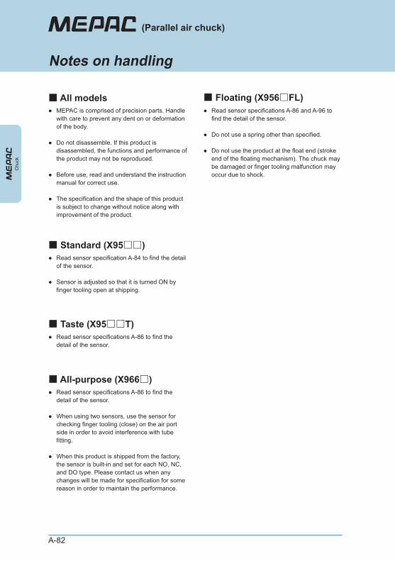
A-82
●
●
●
●
MEPAC is comprised of precision parts. Handle with care to prevent any dent on or deformation of the body.
Do not disassemble. If this product is disassembled, the functions and performance of the product may not be reproduced.
Before use, read and understand the instruction manual for correct use.
The specification and the shape of this product is subject to change without notice along with improvement of the product.
■ Standard (X95□□)●
●
Read sensor specification A-84 to find the detail of the sensor.
Sensor is adjusted so that it is turned ON by finger tooling open at shipping.
■ All-purpose (X966□)
■ Taste (X95□□T)● Read sensor specifications A-86 to find the
detail of the sensor.
■ All models
Chu
ck
(Parallel air chuck)
Notes on handling
●
●
●
Read sensor specifications A-86 to find the detail of the sensor.
When using two sensors, use the sensor for checking finger tooling (close) on the air port side in order to avoid interference with tube fitting.
When this product is shipped from the factory, the sensor is built-in and set for each NO, NC, and DO type. Please contact us when any changes will be made for specification for some reason in order to maintain the performance.
■ Floating (X956□FL)●
●
●
Read sensor specifications A-86 and A-96 to find the detail of the sensor.
Do not use a spring other than specified.
Do not use the product at the float end (stroke end of the floating mechanism). The chuck may be damaged or finger tooling malfunction may occur due to shock.
A-83
● If the spring load for the float is too large, operation of the finger tooling is adversely affected (slow motion, no motion). Therefore, check the following conditions.
Usable conditionFinger tooling open/close thrust > Float load x μ x S
μ: Friction coefficient of workpiece and jawS: Safety rate 1.5 to 2
3. Precautions for use
Normal open (NO)Chuck modelFinger tooling open/close thrust
Normal close (NC)
(N)
X9560FLX9562FL
59
35
●
●
●
●
●
The spring for the float can be replaced only by a maintenance personnel. Turn off the power supply and air supply, and then remove this product from the equipment. The replacement should be performed in an environment where cutting chips or the like do not get into the product. After the replacement, perform the centering of the chuck, which was re-installed on the equipment and sensor adjustment correctly. During the replacement, use caution not to scratch or damage the surface of the chuck main body and floating main body.
4. Replacement of spring for float
1. Description of spring pack
When the spring load of the floating mechanism is too weak in the use of this product and it is not possible to achieve the intended function of the product, use the spring supplied with the product for efficient use of this product. (The standard spring is incorporated in this product at the time of purchase.)
Chuck model Description of spring pack
X9560FL
X9562FL
Middle load (blue) (1), snap ring (1)
Middle load (blue), high load (yellow) 1 for each, snap ring (1)
2. Basic usage
Middle load (blue)Chuck model
Spring type Float load 0 st/5 st
High load (yellow)
(N)
X9560FL
X9562FL
5.7 / 7
6.2 / 7.5 7.9 / 10
*
*
“0 st/5 st” indicated as the float load shows the free state and the position on the float end.
The float load represents the value including the mass of the chuck main body. Use the following figures as a rough indication of the float load when using in the horizontal direction.
X9560FL: Float load - 0.5X9562FL: Float load - 1.0
Spring pack
Chuck
Notes on handling
■ Floating (option)
* Explanation of spring replacement is described in the instruction manual.・ Put a mark as shown as a guide to show the
direction of rotation of the floating main body and chuck.
・ Pull out the chuck from the floating main body.
・
Grip the snap ring firmly with longnose pliers (JIS B4631 Nominal size 150) with the chuck floated, hold it firmly and gently pull it out. In doing this, use caution not to damage the shaft. Damage to the shaft may decrease the life of the product due to malfunction and premature abrasion of the product.
*
*
When the snap ring is removed, the chuck is popped out by the force of the spring. Hold the chuck by hand firmly during replacement work. Dispose of the removed snap ring because it may have been damaged or deformed.
* Do not wipe off grease adhered to the chuck main body.
・ Replace the spring.
・ Insert the chuck into the floating main body with the mark aligned.
・ Insert the supplied snap ring into the groove and push it by hand all the way to the full depth.
・ Check that the float moves smoothly.
* Make sure that snap ring is not wobbling.
* If the float movement is jerky, there is a possibility of the inclusion of foreign matter. If this happens, remove the chuck again, remove the cause for the abnormal condition on the sliding part.
5. Procedure of replacement
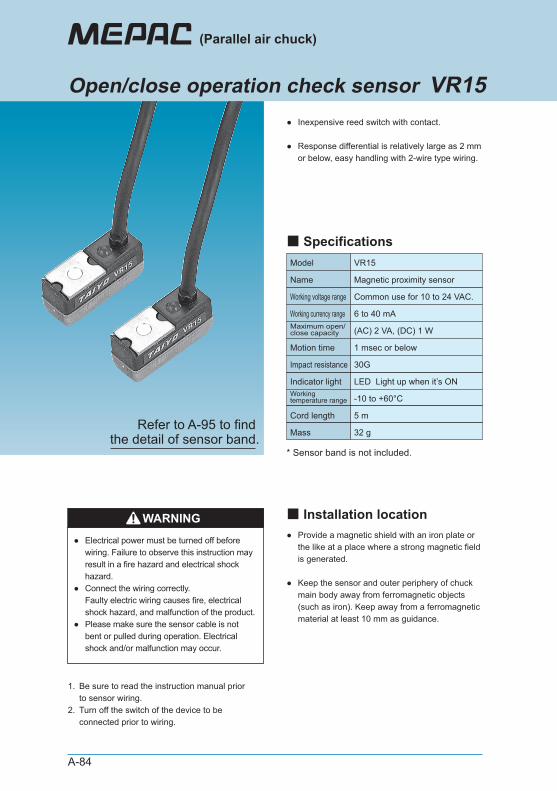
A-84
●
●
Inexpensive reed switch with contact.
Response differential is relatively large as 2 mm or below, easy handling with 2-wire type wiring.
●
●
Provide a magnetic shield with an iron plate or the like at a place where a strong magnetic field is generated.
Keep the sensor and outer periphery of chuck main body away from ferromagnetic objects (such as iron). Keep away from a ferromagnetic material at least 10 mm as guidance.
1.
2.
Be sure to read the instruction manual prior to sensor wiring. Turn off the switch of the device to be connected prior to wiring.
Model VR15
Name Magnetic proximity sensor
Common use for 10 to 24 VAC.
6 to 40 mA
LED Light up when it’s ON
-10 to +60°C
5 m
Working voltage range
Working currency range
(AC) 2 VA, (DC) 1 WMaximum open/close capacity
1 msec or belowMotion time
Indicator light
30GImpact resistance
Workingtemperature range
Cord length
32 gMass
WARNING
●
●
●
Electrical power must be turned off before wiring. Failure to observe this instruction may result in a fire hazard and electrical shock hazard. Connect the wiring correctly. Faulty electric wiring causes fire, electrical shock hazard, and malfunction of the product. Please make sure the sensor cable is not bent or pulled during operation. Electrical shock and/or malfunction may occur.
(Parallel air chuck)
Open/close operation check sensor VR15
■ Installation location
■ Specifications
* Sensor band is not included.
Refer to A-95 to find the detail of sensor band.
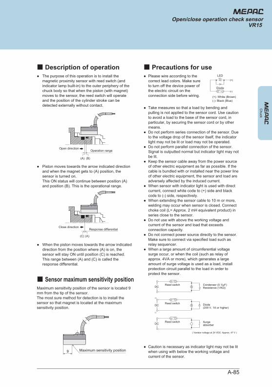
A-85
● The purpose of this operation is to install the magnetic proximity sensor with reed switch (and indicator lamp built-in) to the outer periphery of the chuck body so that when the piston (with magnet) moves to the sensor, the reed switch will operate and the position of the cylinder stroke can be detected externally without contact.
● Please wire according to the correct lead colors. Make sure to turn off the device power of the electric circuit on the connection side before wiring.
●
●
●
●
●
●
●
●
●
Take measures so that a load by bending and pulling is not applied to the sensor cord. Use caution to avoid a load to the base of the sensor cord, in particular, by securing the sensor cord or by other means. Do not perform series connection of the sensor. Due to the voltage drop of the sensor itself, the indicator light may not be lit or load may not be operated. Do not perform parallel connection of the sensor. Signal is outputted normal but indicator light may not be lit. Keep the sensor cable away from the power source of other electric equipment as far as possible. If the cable is bundled with or installed near the power line of other electric equipment, the sensor and load are adversely affected by the induced current. When sensor with indicator light is used with direct current, connect white code to (+) side and black code to (-) side, respectively. When extending the sensor cable to 10 m or more, welding may occur when sensor is closed. Connect choke coil (L= Approx. 2 mH equivalent product) in series close to the sensor. Do not use with above the working voltage and current of the sensor and load that exceeds connection capacity. Do not connect power source directly to the sensor. Make sure to connect via specified load such as relay sequencer. When a large amount of circumferential voltage surge occur, or when the coil (such as relay of approx. 4VA or more), which generates a large amount of surge voltage is used as a load, install protection circuit parallel to the load in order to protect the sensor.
● Caution is necessary as indicator light may not be lit when using with below the working voltage and current of the sensor.
Maximum sensitivity position of the sensor is located 9 mm from the tip of the sensor. The most sure method for detection is to install the sensor so that magnet is located at the maximum sensitivity position.
● Piston moves towards the arrow indicated direction and when the magnet gets to (A) position, the sensor is turned on. This ON status will continue between position (A) and position (B). This is the operational range.
● When the piston moves towards the arrow indicated direction from the position where (A) is on, the sensor will stay ON until position (C) is reached. This range between (A) and (C) is called the response differential.
Close directionResponse differential
(C) (A)
Open directionOperation range
(A) (B)
Maximum sensitivity position9
Reed switch Condenser (0.1/μF)Resistance (1/KΩ)
Diode(200 V, 1A or higher)
( Varistor voltage at 24 VDC: Approx. 47 V )
Surgeabsorber
DC R
Reed switch
(+)
(-)
DC R
Reed switchDC
Diode
LED (+)
(+): White (Brown)(-): Black (Blue)
(-)
Chuck
Open/close operation check sensorVR15
■ Description of operation ■ Precautions for use
■ Sensor maximum sensitivity position
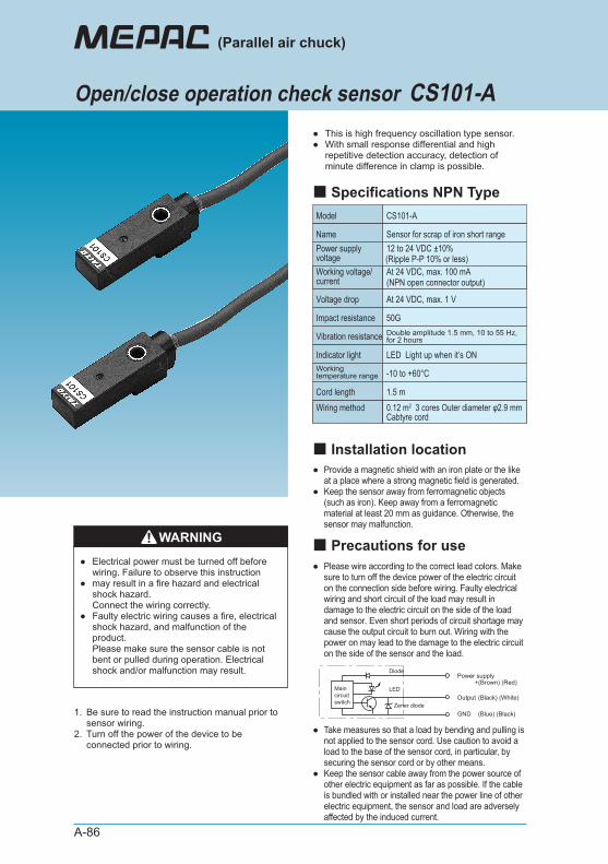
A-86
●●
This is high frequency oscillation type sensor. With small response differential and high repetitive detection accuracy, detection of minute difference in clamp is possible.
●
●
Provide a magnetic shield with an iron plate or the like at a place where a strong magnetic field is generated. Keep the sensor away from ferromagnetic objects (such as iron). Keep away from a ferromagnetic material at least 20 mm as guidance. Otherwise, the sensor may malfunction.
1.
2.
Be sure to read the instruction manual prior to sensor wiring. Turn off the power of the device to be connected prior to wiring.
● Please wire according to the correct lead colors. Make sure to turn off the device power of the electric circuit on the connection side before wiring. Faulty electrical wiring and short circuit of the load may result in damage to the electric circuit on the side of the load and sensor. Even short periods of circuit shortage may cause the output circuit to burn out. Wiring with the power on may lead to the damage to the electric circuit on the side of the sensor and the load.
●
●
Take measures so that a load by bending and pulling is not applied to the sensor cord. Use caution to avoid a load to the base of the sensor cord, in particular, by securing the sensor cord or by other means. Keep the sensor cable away from the power source of other electric equipment as far as possible. If the cable is bundled with or installed near the power line of other electric equipment, the sensor and load are adversely affected by the induced current.
WARNING
●
●
●
Electrical power must be turned off before wiring. Failure to observe this instruction may result in a fire hazard and electrical shock hazard. Connect the wiring correctly. Faulty electric wiring causes a fire, electrical shock hazard, and malfunction of the product. Please make sure the sensor cable is not bent or pulled during operation. Electrical shock and/or malfunction may result.
Model CS101-A
Name Sensor for scrap of iron short range12 to 24 VDC ±10%(Ripple P-P 10% or less)At 24 VDC, max. 100 mA(NPN open connector output)
LED Light up when it’s ON
-10 to +60°C
1.5 m
Power supply voltageWorking voltage/current
At 24 VDC, max. 1 VVoltage drop
50GImpact resistance
Indicator light
Double amplitude 1.5 mm, 10 to 55 Hz, for 2 hoursVibration resistance
Working temperature range
Cord length0.12 m2 3 cores Outer diameter φ2.9 mmCabtyre cord
Wiring method
Diode
Zener diode
LED
Power supply
Output
GND
+(Brown) (Red)
(Black) (White)
(Blue) (Black)
(Parallel air chuck)
Open/close operation check sensor CS101-A
■ Installation location
■ Precautions for use
■ Specifications NPN Type
Main circuit switch
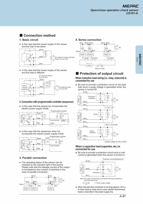
A-87
1. Basic circuit● In the case that the power supply of the sensor
and the load is the same
When inductive load wiring (i.e. relay, solenoid) is connected for use● Be sure to provide a protection circuit on the load
side since a surge voltage is generated when the sensor is turned off.
When a capacitive load (capacitor, etc.) is connected for use● Be sure to provide a protection circuit since a rush
current is generated when the sensor is turned on.
● When the lead wire connection is too long (approx. 20 m), or when there is noise due to a poor electric environment, insert a noise filter in the power supply line.
3. Parallel connection● The operating status of the sensor can be
checked by the indicator light of the sensor. Please note that the leakage current of the output is increased by the number of switches in the case of parallel connection.
2. Connection with programmable controller (sequencer)● In the case that the sequencer incorporates the
electric power supply inside
● In the case that the sequencer does not incorporate the electric power supply inside
● In the case that the power supply of the sensor and the load is different
4. Series connection
Brown
Black
Blue
DC supply for load12 to 24 VDC
DC supply for sensor12 to 24 VDC
Brown
Black
Blue
Programmable controllerDC
InternalpowerInput terminal
COM
Mai
n ci
rcui
tsw
itch
Mai
n cir
cuit
switc
h
Brown
Black
Blue
Programmable controller
DC
Input terminal
COM
BrownBrown
Brown
BlackBlackBlack
BlueBlueBlue
DC
Switch 1 Switch 2 Switch n
Load
BrownBrown
Brown
BlackBlackBlack
BlueBlueBlue
DC
Power for load
Switch 1 Switch 2 Switch n
R1 R2 Rn
Load
R1 contact R2 contact Rn contact
Brown
Black
Blue
DC
0.1 μF, 1 KΩ
Condenserresistance Lo
ad
Sw
itch
non-
cont
act
Brown
Black
Blue
DC
200 V, 1 A or more
Diode
Load
Sw
itch
non-
cont
act
Brown
Black
Blue
DC
Varistor voltage 30 VDC or below
Surgeabsorber Lo
ad
Sw
itch
non-
cont
act
Brown
Black
Blue
DC
Condenser
Protection circuit (Resistance R)
Sw
itch
non-
cont
act
IC
Note) The value of R [Ω] must not be below the value obtained by the following formula.
R= [Ω] V: Power supply voltage0.2V
Chuck
Open/close operation check sensorCS101-A
■ Connection method
■ Protection of output circuit
Main circuit switch
Main circuit switch
Load
Load
Brown
Black
Blue
DC supply for sensor and loadPower 12 to 24 VDC
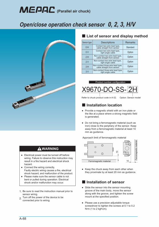
A-88
●
●
Provide a magnetic shield with an iron plate or the like at a place where a strong magnetic field is generated.
Do not bring a ferromagnetic material (such as iron) close to the periphery of the sensor. Keep away from a ferromagnetic material at least 10 mm as guidance.
● Keep the chuck away from each other when they proximate by at least 20 mm as guidance.
1.
2.
Be sure to read the instruction manual prior to sensor wiring. Turn off the power of the device to be connected prior to wiring.
●
●
Slide the sensor into the sensor mounting groove of the main body, move the sensor along with the groove, and tighten the screw mount at the specified position.
Please use a precision adjustable torque screwdriver to tighten the screws at 0.1 to 0.2 N•m (1 to 2 kgf•cm).
WARNING●
●
●
Electrical power must be turned off before wiring. Failure to observe this instruction may result in a fire hazard and electrical shock hazard. Connect the wiring correctly. Faulty electric wiring causes a fire, electrical shock hazard, and malfunction of the product. Please make sure the sensor cable is not bent or pulled during operation. Electrical shock and/or malfunction may occur.
Sensor type Descriptions
0 H
Remarks
StandardContact two-wire lead type,cable straight from sensor
0 V OptionContact two-wire lead type,right angle cable
2 H Non-contact two-wire lead type,cable straight from sensor
2 V Non-contact two-wire lead type, right angle cable
3 H Non-contact three-wire lead type, cable straight from sensor
3 V Non-contact three-wire lead type,right angle cable
X9670-DO-SS-Refer to chuck product code in A-52. Option: Sensor model
2H
Approach limit of ferromagnetic material
10
10Ferromagnetic material
Ferro
mag
netic
mat
eria
l
(Parallel air chuck)
Open/close operation check sensor 0, 2, 3, H/V
■ Installation location
■ List of sensor and display method
■ Installation of sensor
Option
Option
Option
Option
Product number configuration
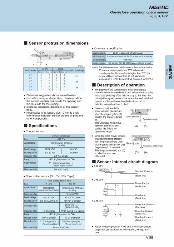
A-89
● The purpose of this operation is to install the magnetic proximity sensor with reed switch (and indicator lamp built-in) to the outer periphery of the cylinder body so that when the piston (with magnet) moves to the sensor, the reed switch will operate and the position of the cylinder stroke can be detected externally without contact.
● Refer to descriptions in A-92 and in the subsequent pages for precautions for connection, wiring, and use.
● Piston moves towards the arrow indicated direction and when the magnet gets to (A) position, the sensor is turned on. This ON status will continue between position (A) and position (B). This is the operational range.
● When the piston moves towards the arrow indicated direction from the position where (A) is on, the sensor will stay ON until the position (C) is reached. This range between (A) and (C) is called the response differential.
●●
●
●
Distances suggested above are estimates. For safest setup and operation, please position the sensor towards minus side for opening and the plus side for the closing. Indicates protrusion dimension of the sensor body. Keep space of at least L plus 10 mm to avoid interference between sensor protrusion part and other components.
V
HL
+ -
Sensor model
0 H 6 -3 0 -822.5
X9670Open end Close end Open end Close end
X9672Sensor body length
0 V 6 -3 0 -82 H 6 -3 -1 -8 18.52 V 5 -3 -3 -73 H 5 -3 -2 -6 18.53 V 7 -3 -1 -9
(mm)
Internal drop voltage
Leakage current
Note 1) The above mentioned load current is the maximum value: 20 mA is at the temperature of 25°C When switch operating ambient temperature is higher than 25°C, the current will become lower than 20 mA. (When the temperature is 60°C, the current will become 5 to 10 mA.)
● Non-contact sensor (3H, 3V NPN Type)
ItemNon-contact sensor type
2H, 2V 3H, 3V
-10 to 30 VDC
5 to 20 mA (Note 1)
-
4 V or smallerLED (Light up when it’s ON)
1mA or smaller
At 24 VDC 10mA or below (When it is ON)
10 to 28 VDC30 VDC or below100 mA or smaller
At 100 mA 0.5 V or smaller
10 μA or smaller
Internal drop voltage
● Contact sensor
ItemContact sensor type
0 H, 0 VProgrammable controller,
for relay
12/24 VDC5 to 50 mA
100 VAC7 to 20 mA
2.4 V or smallerLED (Light up when it’s ON)
294 m/S2 (30G)
980 m/S2 (100G)
Applications
Applications
Load voltage
Load voltage
Loading current
Loading current
Consumption current
Power supply voltage
Lamp
Lamp
Cable length
Cable length
Maximum shock
Maximum shock
1 m Oil proof type vinyl capTire cord 2 cores 0.2 mm2
1 m Oil proof type vinyl capTire cord 2 cores 0.2 mm2
● Common specification20 MΩ or greater with 500 VDC meggerInsulation resistance
Apply pressure for 1 minute with 1000 VAC and there must be no abnormality.Dielectric strength voltage-10 to +60°CAmbient temperature
IEC standard IP67, JIS C0920 (waterproof type), oil proofProtective construction
Open directionOperation range
(A) (B)
Close directionResponse differential
(A)(C)
● 2 H, 2 V
● 3 H, 3 V
● 0 H, 0 V
Brown line (+)(White line)
Blue line (-)(Black line)
Brown line (Power +)(Red line)
Black line (Output)
Brown line(White line)
(White line)Blue line (Power -)
Blue line (Power -)
(Black line)
(Black line)
Chuck
Open/close operation check sensor0, 2, 3, H/V
■ Sensor protrusion dimensions
■ Specifications
■ Description of operation
■ Sensor internal circuit diagram
Dedicated to programmable controller
Programmable controller, for relay
Main circuit switch
Main circuit switch
1 m Oil proof type vinyl capTire cord 3 cores 0.2 mm2
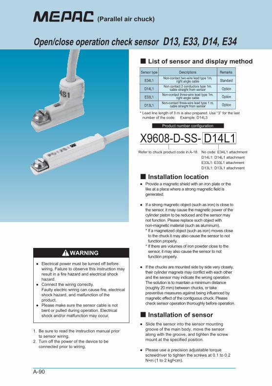
A-90
●
●
●
Provide a magnetic shield with an iron plate or the like at a place where a strong magnetic field is generated.
If a strong magnetic object (such as iron) is close to the sensor, it may cause the magnetic power of the cylinder piston to be reduced and the sensor may not function. Please replace such object with non-magnetic material (such as aluminum). * If a magnetized object (such as iron) moves close
to the chuck it may also cause the sensor to not function properly.
* If there are volumes of iron powder close to the sensor, it may also cause the sensor to not function properly.
If the chucks are mounted side by side very closely, their cylinder magnets may conflict with each other and the sensor may indicate the wrong operation. The solution is to maintain a minimum distance (roughly 20 mm) between chucks, or take preventive measures against being influenced by magnetic effect of the contiguous chuck. Please check sensor operation thoroughly before operation.
1.
2.
Be sure to read the instruction manual prior to sensor wiring. Turn off the power of the device to be connected prior to wiring.
●
●
Slide the sensor into the sensor mounting groove of the main body, move the sensor along with the groove, and tighten the screw mount at the specified position.
Please use a precision adjustable torque screwdriver to tighten the screws at 0.1 to 0.2 N•m (1 to 2 kgf•cm).
WARNING●
●
●
Electrical power must be turned off before wiring. Failure to observe this instruction may result in a fire hazard and electrical shock hazard. Connect the wiring correctly. Faulty electric wiring can cause fire, electrical shock hazard, and malfunction of the product. Please make sure the sensor cable is not bent or pulled during operation. Electrical shock and/or malfunction may occur.
Sensor type Descriptions
E34L1
Remarks
StandardNon-contact two-wire lead type 1m,right angle cable
D14L1 OptionNon contact 2 conductors type 1m,cable straight from sensor
E33L1 OptionNon-contact three-wire lead type 1m,right angle cable
D13L1 OptionNon-contact three-wire lead type 1 m,cable straight from sensor
X9608-D-SS-Refer to chuck product code in A-18. No code: E34L1 attachment
D14L1: D14L1 attachmentE33L1: E33L1 attachmentD13L1: D13L1 attachment
D14L1
Open/close operation check sensor D13, E33, D14, E34
(Parallel air chuck)
■ Installation location
■ List of sensor and display method
■ Installation of sensor
* Lead line length of 3 m is also prepared. Use “3” for the last number of the code. Example: D14L3
Product number configuration
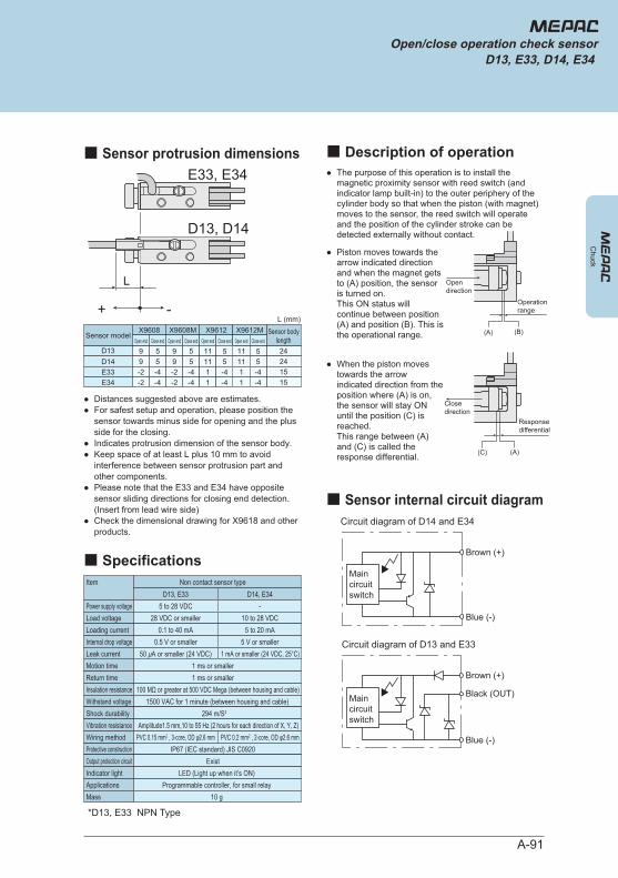
A-91
● The purpose of this operation is to install the magnetic proximity sensor with reed switch (and indicator lamp built-in) to the outer periphery of the cylinder body so that when the piston (with magnet) moves to the sensor, the reed switch will operate and the position of the cylinder stroke can be detected externally without contact.
● Piston moves towards the arrow indicated direction and when the magnet gets to (A) position, the sensor is turned on. This ON status will continue between position (A) and position (B). This is the operational range.
● When the piston moves towards the arrow indicated direction from the position where (A) is on, the sensor will stay ON until the position (C) is reached. This range between (A) and (C) is called the response differential.
●●
●●
●
●
Distances suggested above are estimates. For safest setup and operation, please position the sensor towards minus side for opening and the plus side for the closing. Indicates protrusion dimension of the sensor body. Keep space of at least L plus 10 mm to avoid interference between sensor protrusion part and other components. Please note that the E33 and E34 have opposite sensor sliding directions for closing end detection. (Insert from lead wire side)Check the dimensional drawing for X9618 and other products.
Sensor model
D13 9 5 24241515
X9608Open end Close end Open end Close end
X9608M Sensor bodylength
D14 9 5E33 -2 -4E34 -2 -4
9 59 5-2 -4-2 -4
11 5
X9612Open end Close end Open end Close end
X9612M
11 51 -41 -4
11 511 51 -41 -4
L (mm)
Item Non contact sensor typeD13, E33 D14, E34
5 to 28 VDC28 VDC or smaller
0.1 to 40 mA
1 ms or smaller
-10 to 28 VDC
5 to 20 mA
Power supply voltageLoad voltageLoading current
0.5 V or smaller 5 V or smaller
PVC 0.15 mm2 , 3-core, OD φ2.6 mm PVC 0.2 mm2 , 2-core, OD φ2.6 mm
Internal drop voltage50 μA or smaller (24 VDC) 1 mA or smaller (24 VDC, 25°C)Leak current
Motion time1 ms or smallerReturn time
IP67 (IEC standard) JIS C0920Protective constructionExistOutput protection circuit
LED (Light up when it’s ON)Indicator lightProgrammable controller, for small relayApplications
10 gMass
100 MΩ or greater at 500 VDC Mega (between housing and cable)Insulation resistance1500 VAC for 1 minute (between housing and cable)Withstand voltage
294 m/S2Shock durabilityAmplitude1.5 mm,10 to 55 Hz (2 hours for each direction of X, Y, Z)Vibration resistance
Wiring method
Chuck
Open/close operation check sensorD13, E33, D14, E34
■ Sensor protrusion dimensions
■ Specifications
■ Description of operation
■ Sensor internal circuit diagram
L
+ -
D13, D14
E33, E34
Operationrange
Responsedifferential
(A) (B)
(C) (A)
Closedirection
Opendirection
Blue (-)
Brown (+)
Black (OUT)
Blue (-)
Brown (+)
Circuit diagram of D14 and E34
Circuit diagram of D13 and E33
*D13, E33 NPN Type
Main circuit switch
Main circuit switch
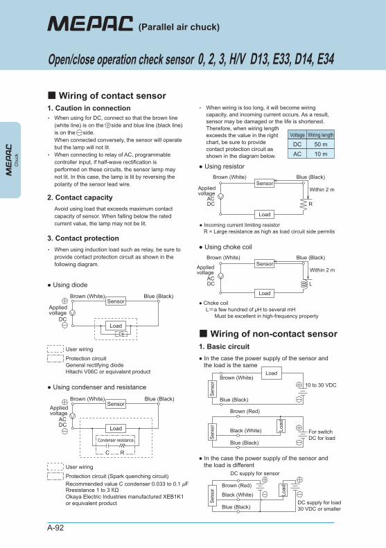
A-92
1. Caution in connection
1. Basic circuit
・
・
When using for DC, connect so that the brown line (white line) is on the side and blue line (black line) is on the side. When connected conversely, the sensor will operate but the lamp will not lit. When connecting to relay of AC, programmable controller input, if half-wave rectification is performed on these circuits, the sensor lamp may not lit. In this case, the lamp is lit by reversing the polarity of the sensor lead wire.
・ When wiring is too long, it will become wiring capacity, and incoming current occurs. As a result, sensor may be damaged or the life is shortened. Therefore, when wiring length exceeds the value in the right chart, be sure to provide contact protection circuit as shown in the diagram below.
3. Contact protection・ When using induction load such as relay, be sure to
provide contact protection circuit as shown in the following diagram.
2. Contact capacityAvoid using load that exceeds maximum contact capacity of sensor. When falling below the rated current value, the lamp may not be lit.
● Using diode
● Using condenser and resistance
Appliedvoltage
DC
Brown (White)
User wiring
Protection circuitGeneral rectifying diodeHitachi V06C or equivalent product
Blue (Black)Sensor
Load
Appliedvoltage
ACDC
Brown (White)
Condenser resistance
User wiring
Protection circuit (Spark quenching circuit)Recommended value C condenser 0.033 to 0.1 μFRresistance 1 to 3 KΩOkaya Electric Industries manufactured XEB1K1 or equivalent product
Blue (Black)Sensor
Load
RC
Voltage Wiring length
DC 50 mAC 10 m
● Using resistor
● Incoming current limiting resistorR = Large resistance as high as load circuit side permits
Brown (White) Blue (Black)
Within 2 mAppliedvoltage
ACDC
Sensor
Load
R
● Using choke coil
● Choke coilL=a few hundred of μH to several mH
Must be excellent in high-frequency property
Brown (White) Blue (Black)
Within 2 mAppliedvoltage
ACDC
Sensor
Load
L
Brown (White)
Blue (Black)
Brown (Red)
Black (White)
Blue (Black)
Sens
orSe
nsor Lo
ad
10 to 30 VDC
For switchDC for load
Load
● In the case the power supply of the sensor and the load is the same
Brown (Red)
Black (White)
Blue (Black)
Sens
or Load
DC supply for load30 VDC or smaller
DC supply for sensor
● In the case the power supply of the sensor and the load is different
Open/close operation check sensor 0, 2, 3, H/V D13, E33, D14, E34
(Parallel air chuck)
■ Wiring of contact sensor
■ Wiring of non-contact sensor
Chu
ck
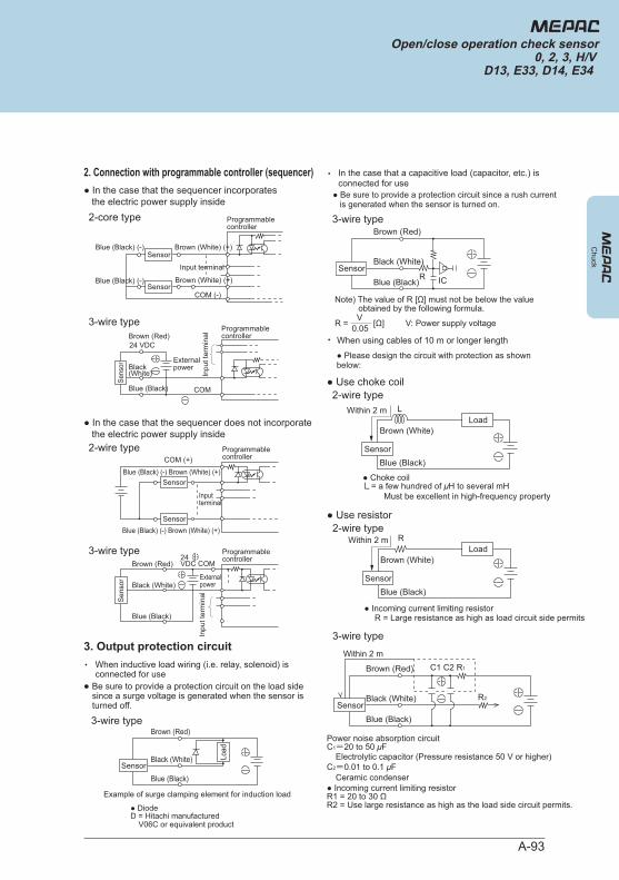
A-93
3-wire type
● In the case that the sequencer does not incorporate the electric power supply inside2-wire type
3-wire type
Inputterminal
Blue (Black) (-) Brown (White) (+)
Blue (Black) (-) Brown (White) (+)
COM (+)Programmablecontroller
Sensor
Sensor
Inpu
t ter
min
al
Brown (Red)
Black (White)Externalpower
Blue (Black)
24VDC COM
Programmablecontroller
Sen
sor
Brown (Red)
Black(White)
Blue (Black)
Sens
or
Inpu
t ter
min
al
Programmablecontroller
Externalpower
COM
24 VDC
3. Output protection circuit・ When inductive load wiring (i.e. relay, solenoid) is
connected for use
3-wire typeBrown (Red)
Black (White)
Example of surge clamping element for induction load
● DiodeD = Hitachi manufactured
V06C or equivalent product
Blue (Black)
Load
Sensor
● Be sure to provide a protection circuit on the load side since a surge voltage is generated when the sensor is turned off.
3-wire type
Note) The value of R [Ω] must not be below the value obtained by the following formula.
R = [Ω] V: Power supply voltage0.05V
Brown (Red)
ICR
Black (White)
Blue (Black)Sensor
● Incoming current limiting resistor
Power noise absorption circuitC1=20 to 50 μF
Electrolytic capacitor (Pressure resistance 50 V or higher)C2=0.01 to 0.1 μF
● Incoming current limiting resistorR1 = 20 to 30 ΩR2 = Use large resistance as high as the load side circuit permits.
Ceramic condenser
R = Large resistance as high as load circuit side permits
● Use choke coil
● Use resistor
Brown (Red)
Within 2 mC1 C2 R1
R2Black (White)
Blue (Black)Sensor
● Choke coilL= a few hundred of μH to several mH
Must be excellent in high-frequency property
Within 2 m L
Brown (White)
Blue (Black)Sensor
Within 2 m R
Brown (White)
Blue (Black)Sensor
Load
2-wire type
2-wire type
3-wire type
・ When using cables of 10 m or longer length
● Please design the circuit with protection as shown below:
・ In the case that a capacitive load (capacitor, etc.) is connected for use
● Be sure to provide a protection circuit since a rush current is generated when the sensor is turned on.
2. Connection with programmable controller (sequencer)● In the case that the sequencer incorporates the electric power supply inside2-core type
SensorCOM (-)
Input terminal
Brown (White) (+)
Blue (Black) (-)
Blue (Black) (-)
Brown (White) (+)
Programmablecontroller
Sensor
Load
Chuck
Open/close operation check sensor0, 2, 3, H/V
D13, E33, D14, E34

A-94
● Use caution in wiring connection so that the lead wire is not subjected to repeated bending stress and tensile force. Use high-flex cables such as electric wire for robot for the movable part.
● Parallel connection [0, 2, 3, H/V only]
● Series connection [0, 2, 3, H/V only]
・
・
・
When multiple two-wire type sensors are connected for use, leakage current will increase by the number of connections. Therefore, make sure to confirm the specification of the load and determine the number of connections. However, the lamp of the sensor may become darker or may not be lit.
For two-wire type sensor, up until one sensor is turned on and turned off, the voltage of both ends of the sensor, which was connected in parallel, will drop up to the internal drop voltage value when the sensor is ON and fall below the load voltage range. As a result, other sensors will not be turned on. Therefore, make sure to check input specification of the programmable controller, which is the connection load, before use.
Leakage current value of the three-wire non-connection type sensor is very small (10 μA or smaller), therefore, it will not cause problem during the normal use.
● There is a case when D13, E33, D14, and E34 cannot be used by combining with load, therefore, avoid connecting multiple sensors (direct and parallel connection).
・
・
・
When multiple two-wire type sensors are connected in series, voltage drop at the sensor becomes the total of voltage drop at all connected sensors. The voltage applied to the load side is the power voltage minus the voltage drop at the sensors. Make sure to check the specification of the load and determine the number of connections.
When multiple three-wire type sensors are connected for use in series, voltage drop at the sensor becomes the total of voltage drop at all connected sensors, same as the above two-wire type sensors. In addition, the current flows in the sensor is the total of consumption current and load current of the connected sensor as shown in the diagram below. Therefore, in order to avoid exceeding maximum load current of the sensor, make sure to check the specification of the load and determine the number of connections.
The lamp is lit when all sensors are turned ON.
Brown (Red)
Black(White)
Blue (Black)Loading current + Consumption current x (n - 2)
Sen
sor
No. n
Sen
sor
No. 2
Sen
sor
No. 1
Load
Brown (Red)Black
(White)
Blue (Black)
Loading current + Consumption current x 2
Brown (Red)
Black (White)
Blue (Black)
Loading current
For sensorDC supply for load
Consumptioncurrent
Consumptioncurrent
Consumptioncurrent
Loading current + Consumption current
●
●
Please wire according to the correct lead colors. Make sure to turn off the device power of the electric circuit on the connection side before wiring. Faulty electrical wiring and short circuit of the load may result in damage to the electric circuit on the side of the load and sensor. Even short periods of circuit shortage may cause the output circuit to burn out. Wiring with the power on may lead to the damage to the electric circuit on the side of the sensor and the load.
Take measures so that a load by bending and pulling is not applied to the sensor cord. Use caution to avoid a load to the base of the sensor cord, in particular, by securing the sensor cord or by other means. Keep the sensor cable away from the power source of other electric equipment as far as possible. If the cable is bundled with or installed near the power line of other electric equipment, the sensor and load are adversely affected by the induced current.
Chu
ck
(Parallel air chuck)
Open/close operation check sensor 0, 2, 3, H/V D13, E33, D14, E34
■ Wiring precautions
■ Precautions for use
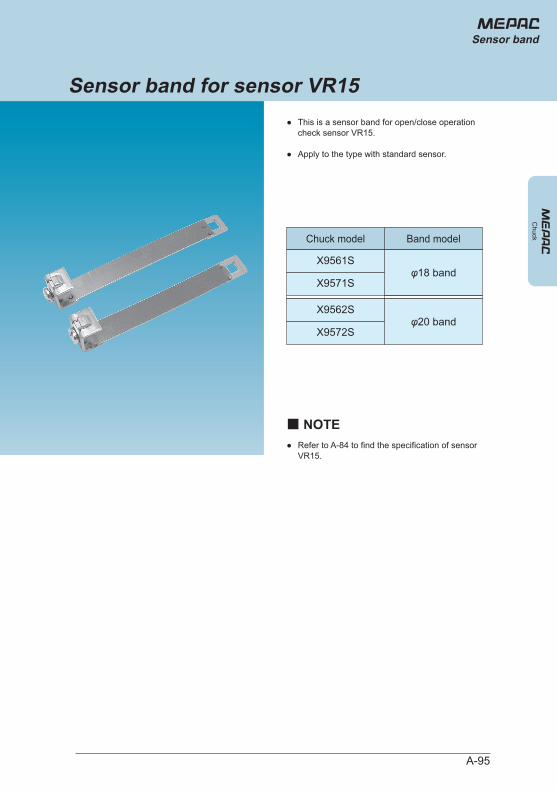
Chuck
●
●
This is a sensor band for open/close operation check sensor VR15.
Apply to the type with standard sensor.
● Refer to A-84 to find the specification of sensor VR15.
Chuck model Band model
X9561S
X9571Sφ18 band
X9562S
X9572Sφ20 band
Sensor band for sensor VR15
■ NOTE
A-95
Sensor band
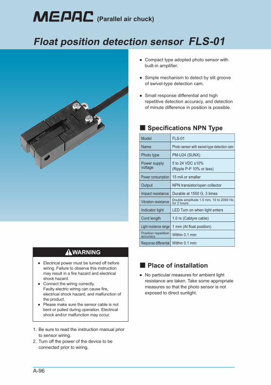
A-96
●
●
●
Compact type adopted photo sensor with built-in amplifier.
Simple mechanism to detect by slit groove of swivel-type detection cam.
Small response differential and high repetitive detection accuracy, and detection of minute difference in position is possible.
● No particular measures for ambient light resistance are taken. Take some appropriate measures so that the photo sensor is not exposed to direct sunlight.
1.
2.
Be sure to read the instruction manual prior to sensor wiring. Turn off the power of the device to be connected prior to wiring.
WARNING
●
●
●
Electrical power must be turned off before wiring. Failure to observe this instruction may result in a fire hazard and electrical shock hazard. Connect the wiring correctly. Faulty electric wiring can cause fire, electrical shock hazard, and malfunction of the product. Please make sure the sensor cable is not bent or pulled during operation. Electrical shock and/or malfunction may occur.
Model FLS-01
Name Photo sensor with swivel-type detection cam
Photo type PM-U24 (SUNX)
5 to 24 VDC ±10%(Ripple P-P 10% or less)
15 mA or smaller
LED Turn on when light enters
Within 0.1 mm
1.0 m (Cabtyre cable)
Power supply voltage
Power consumption
NPN transistor/open collectorOutput
Durable at 1500 G, 3 timesImpact resistance
Indicator light
Double amplitude 1.5 mm, 10 to 2000 Hz,for 2 hoursVibration resistance
Position repetitionaccuracy
Within 0.1 mmResponse differential
Cord length
1 mm (At float position)Light incidence range
(Parallel air chuck)
Float position detection sensor FLS-01
■ Place of installation
■ Specifications NPN Type
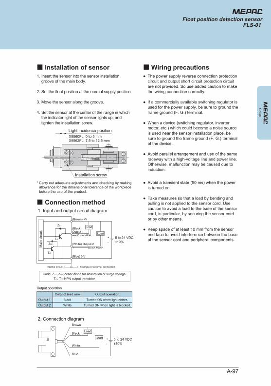
A-97
1.
2.
3.
4.
Insert the sensor into the sensor installation groove of the main body.
Set the float position at the normal supply position.
Move the sensor along the groove.
Set the sensor at the center of the range in which the indicator light of the sensor lights up, and tighten the installation screw.
●
●
●
●
The power supply reverse connection protection circuit and output short circuit protection circuit are not provided. So use added caution to make the wiring connection correctly.
If a commercially available switching regulator is used for the power supply, be sure to ground the frame ground (F. G.) terminal.
When a device (switching regulator, inverter motor, etc.) which could become a noise source is used near the sensor installation place, be sure to ground the frame ground (F. G.) terminal of the device.
Avoid parallel arrangement and use of the same raceway with a high-voltage line and power line. Otherwise, malfunction may be caused due to induction.
●
●
●
Avoid a transient state (50 ms) when the power is turned on.
Take measures so that a load by bending and pulling is not applied to the sensor cord. Use caution to avoid a load to the base of the sensor cord, in particular, by securing the sensor cord or by other means.
Keep space of at least 10 mm from the sensor end face to avoid interference between the base of the sensor cord and peripheral components.
Installation screw
Light incidence positionX9560FL: 0 to 5 mmX9562FL: 7.5 to 12.5 mm
1. Input and output circuit diagram
2. Connection diagram
5 to 24 VDC±10%
Brown
Blue
Black
White
Load
Load +-
Mai
n ci
rcui
t
5 to 24 VDC±10%
ZD1
(Brown) +V
(Blue) 0 V
(Black) Output 1
(White) Output 2
Tr1
Tr2
ZD2
Load
Load50 mA MAX
Example of external connectionInternal circuit
50 mA MAX
+-
Code: ZD1, ZD2: Zener diode for absorption of surge voltageTr1, Tr2: NPN output transistor
Color of lead wire Output operation
Output 1
Output 2Black
White
Turned ON when light enters.
Turned ON when light is blocked.
Output operation
Chuck
Float position detection sensorFLS-01
■ Installation of sensor ■ Wiring precautions
■ Connection method
* Carry out adequate adjustments and checking by making allowance for the dimensional tolerance of the workpiece before the use of the product.
Chu
ck
A-98
(Parallel air chuck)
This MEPAC (parallel air chuck) is a product to clamp workpiece installed by automatic machine by clamp unit, which is operated by compressed air. (Mecha type is external drive.)
DANGER
CAUTION
● Do not use the product for the following applications.
● Do not use the product in a place where hazardous substances such as combustible or flammable substances exist. There is a possibility of the product catching fire.
● Do to apply force to the main body and press fit or draw out the workpiece. Product may be damaged and injury may occur.
● Do not spin the body with high speed. Due to the decrease in clamp force by centrifugal force, the workpiece falls off, which may result in a personal injury.
● Do not apply exponential shock. Otherwise, the chuck may be damaged or the finger malfunctions, and the workpiece falls off due to decrease in clamp force, which may result in a personal injury.
● When mounting the product, ensure reliable retention and securing. Otherwise, fall or abnormal operation of the product may cause injury.
● Do not use this product in places subjected to direct sunlight (ultraviolet light) or dust, iron, iron powder, or in an atmosphere containing organic solvent, phosphate-ester hydraulic oil, sulphurous acid gas, chlorine gas, acids, etc. The product may stop functioning in a short period of time, or the performance may be deteriorated and the lifetime of the product may be significantly reduced.
● Be sure to confirm the safety of the operating range of devices before supplying air to and operating the product. If the air is supplied improperly, there is a risk of injury caused by contact with a movable part.
● Keep away from the operating range of machinery when a product is in operation or ready to operate. Failure to do so may result in injury due to unexpected operation of the product.
● Be sure to completely remove the supply of air before performing various tasks such as maintenance, inspection, service, or replacement.
● Do not use the floating type at the float end(stroke end of the floating mechanism). If it is used at the float end, the chuck may be damaged or the finger malfunctions, and the workpiece falls off, which may result in a personal injury.
● Never modify the product. Doing so may cause injury due to abnormal operation, electric shock, fire, etc.
● Do not perform improper disassembly/assembly that affects the product's basic structure, performance, or functions.
● Do not pour water on the product. Pouring water on the product, washing it or using it immersed in water may cause injury due to abnormal operation, electric shock, fire, etc.
1.
2.
3.
Medical devices related to the support and maintenance of human life and bodyMechanisms and machinery used for the purpose of moving and transporting peopleImportant security components of machineryThis product is not developed or designed for applications that require a high degree of safety. Use of this product for such applications may cause death.
WARNING● Do not throw the product into the fire.
Product may be damaged or poisonous gases may be discharged.
Applications
1. Restriction of applications
2. Safety precautions
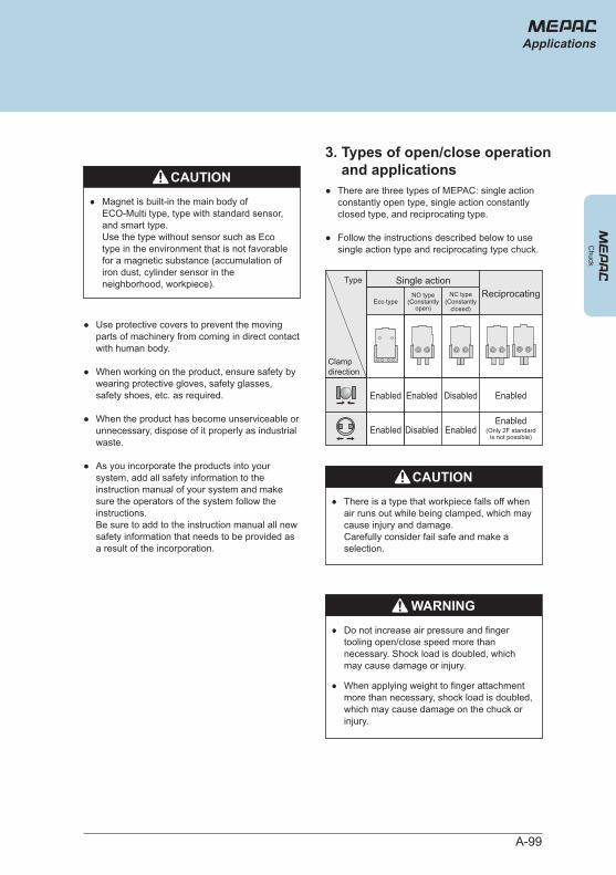
A-99
Chuck
●
●
There are three types of MEPAC: single action constantly open type, single action constantly closed type, and reciprocating type.
Follow the instructions described below to use single action type and reciprocating type chuck.
●
●
●
●
Use protective covers to prevent the moving parts of machinery from coming in direct contact with human body.
When working on the product, ensure safety by wearing protective gloves, safety glasses, safety shoes, etc. as required.
When the product has become unserviceable or unnecessary, dispose of it properly as industrial waste.
As you incorporate the products into your system, add all safety information to the instruction manual of your system and make sure the operators of the system follow the instructions. Be sure to add to the instruction manual all new safety information that needs to be provided as a result of the incorporation.
(Only 2F standardis not possible)
WARNING● Do not increase air pressure and finger
tooling open/close speed more than necessary. Shock load is doubled, which may cause damage or injury.
● When applying weight to finger attachment more than necessary, shock load is doubled, which may cause damage on the chuck or injury.
CAUTION● There is a type that workpiece falls off when
air runs out while being clamped, which may cause injury and damage. Carefully consider fail safe and make a selection.
CAUTION● Magnet is built-in the main body of
ECO-Multi type, type with standard sensor, and smart type. Use the type without sensor such as Eco type in the environment that is not favorable for a magnetic substance (accumulation of iron dust, cylinder sensor in the neighborhood, workpiece). Single action
Enabled
Disabled
Disabled
Enabled
Enabled
Enabled
Type
Clampdirection
NO type(Constantly
open)
NC type(Constantly
closed)
Enabled
Enabled
Eco typeReciprocating
Applications
3. Types of open/close operation and applications