Embed Size (px)
Citation preview

PARABOLIDA AND HALF TUBES BAFFLE BLOCK
PERFORMANCE TO REDUCE OF LENGTH ENERGY FLOW, AND
HYDRAULIC JUMP ON USBR TYPE II STILLING BASIN.
FINAL PROJECT
Requirements reached bachelor
degree of S-1 Civil Engineering
Submitted by :
Muhammad Yogi Prasetyo
NIM: D 100 112 012
CIVIL ENGINEERING DEPARTMEN
ENGINEERING FACULTY
UNIVERSITAS MUHAMMADIYAH SURAKARTA
2016
i
ii

iii
1
PARABOLIDA AND HALF TUBES BAFFLE BLOCK
PERFORMANCE TO REDUCE OF LENGTH ENERGY FLOW,
AND HYDRAULIC JUMP ON USBR TYPE II STILLING BASIN.
Abstract
Scouring that occurs downstream of the stilling basin weir respective
common. stilling basin scour downstream of the weir will cause damage not only
to the base and the river bank, but also can damage the floor of the stilling basin
weir, so it could damage the structure of the weir, so the age of the weir is not in
compatible with the age of the plan. Stilling basin scouring on downstream is
caused by several factors such as the energy flow and the height of the flow rate.
The presence of hydraulic jump planned in stilling basin of the weir actually can
reduce the flow of energy, but the real reality on the ground is still occur scouring
downstream stilling basin.
This study determine to know baffle block performance types parabolaida
(parabolic three-dimensional) and baffle block half tube to reduce the energy flow
of water and reduce the length of hydraulic jump. With presence of the reduction
energy flow and the length of hydraulic jump, the water hazard scouring
downstream weir can be reduced significantly, so that damage the base and the
cliffs of channels (streams) or damage stilling basin weir on stilling basin can be
avoided.
This research was conducted using the open channel flow flume facility in
the Department of Civil Engineering, Faculty of Engineering UMS, the flume
length of 10m, width of 60 cm and a maximum discharge of flow of 6000 cm3/s.
Ogee spillway weir design using an stilling basin USBR type II and shaped of
baffle block design parabolaida and half tubes. Baffle blocks placement in two
layers and placed in 3 place on the stilling basin of the weir, at the 1/3 beginning,
middle, 1/3 the end of stilling basin of the weir. The discharge that use varies from
3500 cm3/s - 6000 cm
3/s (as many as 6 variations of discharge). Baffle blocks
performance to reduce the energy and length hydraulic jump of water use the ogee
spillway and stilling basin USBR II (without baffle block). From the comparison
we can conclude effectively shape of baffle block and baffle blocks placement
most optimal to reduce the energy flow water and the length of hydraulic jump.
Key words: Parabolida baffle block, Half tubes baffle block,Hydraulika, Reduce
Energy Flow, Hydraulic Jump, Stilling Basin USBR Type
Abstract
Gerusan yang terjadi di hilir kolam olak suatu bendung masing sering
terjadi. Gerusan kolam olak dihilir bendung ini akan menyebabkan kerusakan
tidak saja pada dasar dan tebing sungai, akan tetapi juga dapat merusakkan lantai
kolam olak bendung, sehingga dapat merusakkan struktur bendung, sehingga

2
umur bendung tidak sesuai dengan umur rencananya. Gerusan di hilir kolam olak
disebabkan oleh beberapa faktor antara lain faktor energi aliran, dan kecepatan
aliran yang masih tinggi. Adanya loncatan air yang direncanakan di kolam olak
suatu bendung di satu sisi dapat meredam energi aliran, akan tetapi kenyataan
real di lapangan masih terjadi gerusan di hilir kolam olak.
Penelitian ini berusaha mengetahui unjukkerja dari baffle block jenis
parabolaida (parabola 3 dimensi) dan baffle block setengah tabung untuk meredam
energi aliran, maupun meredam panjang loncat air. Dengan adanya peredaman
dari energi aliran, serta panjang loncat air maka bahaya gerusan di hilir bendung
dapat direduksi secara signifikan, sehingga kerusakan dasar dan tebing saluran
(sungai) maupun kerusakan lantai kolam olak bendung dapat dihindari.
Penelitian ini dilakukan dengan menggunakan fasilitas flume aliran
saluran terbuka di Jurusan Teknik Sipil Fakultas Teknik UMS, dengan panjang
flume 10m, lebar 60 cm dan debit maksimum 5000 cm3/dt. Desain bendung
menggunakan pelimpah ogee dan kolam olak tipe USBR tipe 2 dan desain baffle
block berbentuk parabolaida serta setengah tabung. Susunan baffle block disusun
secara 2 lapis dan diletakkan di 4 tempat pada lantai kolam olak, yaitu pada kaki
bendung (awal kolam olak), sepertiga awal kolam olak, tengah-tengah kolam olak
dan duapertiga kolam olak. Debit yang dipergunakan debit yang bervariasi dari
3500 cm3/dt – 5000 cm
3/dt (sebanyak 4 variasi debit). Unjukkerja baffle block
untuk meredam energi dan panjang loncat air dibandingkan dengan unjukkerja
bendung pelimpah ogee serta kolam olak USBR tipe 2 (tanpa baffle block). Dari
perbandingan tersebut dapat disimpulkan jenis baffle block dan susunan baffle
block yang paling optimal untuk meredam energi aliran, serta meredam panjang
loncat air.
Key words: Parabolida baffle block, Half tubes baffle block,Hydraulika, Reduce
Energy Flow, Hydraulic Jump, Stilling Basin USBR Type.
1. INTRODUCTION
The water avaibility is plentiful and the rapid development in the field of irrigation in Indonesia
needs to be managed properly, so that water functions can be utilized optimally. One of the
infrastructures of water is used to optimize the use of water resources is a weir.
Weirs is ones of many a waterworks were built across the river to elevate the river water
level and stem the flow of the river so that the river flow can be tapped and channeled by gravity to
the needed area .
The elevation of river water level velocity and the water depth reduce results the rapids
flow at downstream of the weir. In the stilling basin occur the change flow type, from subcritical to
supercritical, couse hydraulic jump. The length of the hydraulic jump depends on the velocity,
discharge of the flow, channel bottom slope and roughness of the channel. The hydraulic jump
result loss of energy flow, so that the velocity of downstream becomes lower. But the reality on the
2
ground are often scour the riverbed downstream the stilling basin. In order to reduce energy flow,
length hydraulic jump and turbulence of flow, then added parabolaida and half-tube baffle block in
stilling basin. With the placement of baffle blocks, it is expected the energy flow, length jump water
and turbulence become lower and scouring at the downstream stilling basin is getting smaller.
This study sought to know the composition of the double baffle block half tube or
parabolaida most optimal in reduce the flow of energy, the length of hydraulic jump and the water
flow turbulence.
1.1 Problem States
The problem states presented as follows:
1. Effect the performance parabolaida concave baffle block, and the half-tubes baffle block to
reduce the turbulence of flow on stilling basin USBR II.
2. Effect the performance parabolaida concave baffle block, and the half-tube baffle block to
reduce the length of hydraulic jump on a stilling basin USBR II.
3. Effect the performance parabolaida concave baffle block, and the half- tubes baffle block to
reduce the energy flow.
1.2 Research Object
The purpose of this research proposal is to determine the type and placement half- tube or
parabolaidaof baffle blocks most effective to reduce the flow of energy, water turbulence and the
length of hydraulic jump on a stilling basin USBR II.
1.3 Limitation of Problem
To limit the scope of the object of this research that systematic and purposeful stride, it is necessary
limitations problem as follows:
1. Experiments in this study conducted at the Laboratory of Hydraulics Civil Engineering
Program Faculty of Engineering, University of Muhammadiyah Surakarta by using a
channel / flume of flexy glass material which becomes an open channel model with a size of
30 cm x 60 cm x 1000 cm.
2. The flume is considered waterproof and resistant to erosion.
3. Slope of the flume is 0,0058.
4. The type of flow is steady uniform flow
5. Roughness models and channels were not reviewed.
6. The kinematic viscosity throughout the flow being equal.
3
7. Experiment only use four variations of discharge: 3500 cm3/s, 4000 cm
3/s, 4500 cm
3/s, 5000
cm3/s, 5500 cm
3/s and 6000 cm
3/s
8. Experiment using only one kind of variation of the slope of the downstream Ogee spillway.
9. Using a 4 variation of placement of 2 layers of baffle blocks, parabolaida and half tube.
10. Using ogeespillway and thestilling basin USBR II with the addition of parabolaida and half
tube baffle block.
1.3 Benefits Research
The benefits of this research trials are expected this following:
1. Being considerations in planning spillway weir especially on models with stilling basin
USBR II
2. Being reference baffle arrangement blocks the use of the most effective and economical as
energy absorbers.
2. LITERATURE REVIEW
Some similar research about energy reducer on the stilling basin that has been conducted is as
follows:
Pembra (20l3) studied the effect of slope variations in the downstream of weir and the
placement of baffle blocks on the solid roller bucket stilling basin affect the length hydraulic jump
and energy flow reduction. From the results is obtained that baffle blocks which are placed in the
middle of the arch radius is the most effective for reducing the turbulent flow on the downstream of
stilling basin.
Ardian (2014) studied the effect of slope variations in downstream of the spillway and the
placement of baffle blocks on the trajectory bucket stilling basin affect the length hydraulic jump
and energy flow reduction. The result is showed that baffle blocks which is the most effective to
reduce the stilling basin length of hydraulic jump is on the position at the end of an arch of stilling
basin.
Nurrizal (2015) studied the effect of the placement of the concave half circle and parabolic
baffle block on the weir with the solid roller bucket stilling basin affect the length of hydraulic jump
and energy flow loss. And the most effective baffle block to reduce the energy flow and reduce the
length of hydraulic jump is the baffle block with the concave parabolic shaped, with its position is
between the beginning and the middle of the stilling basin curved.

4
While, this research conducted by the author is original and has never been conducted by
anyothers, namely research is aboutParabolida and Half Tubes Baffle Block Performance to
Reduce Energy Flow, and Hydraulic Jump on Stilling Basin USBR Type II.
3. BASIC THEORY
3.1 Flow in Weirs
Type of flow in weirs is stream channel open channel water, the classification type of flow that
occurs in open channels can be based on various criteria including water depth (h), time (t), and
slope (s).
Based on a time function, the flow can be differences into:
1. Steady flow
Steady flow where water depth (h) unchanged in one interval of time as well velocity (v)
does not change according to the time. An example of a fixed flow is a flow on irrigation
drainage channels for long periods
2. Unsteady Flow
That is when the water depth (h) change according to the time also commands to velocity
changed according to time. An example of this flow is on the River flow during flood
discharge with distinction.
Based on a function space, the flow can be differences into:
1. Uniform flow
Unchanged flow average velocity, depth, flow, and discharge cross-section trajectory.
2. Non-uniform flow
Changing flow average velocity, depth, flow, and discharge cross-section trajectory.
4. RESEARCH METHODS
4.1 Research Location
This research is conducted in the hydraulic laboratory of CivilEngineeringDepartment, Universitas
Muhammadiyah Surakarta.
4.2 Research Implementation
Experimental research steps are as follows:
5
1. Prepare tools and materials research
2.Baffle block placement on spillway with the appropriate form of variation
3. Drain the water in the flume with the setted discharge.
4. Set the tail gate to keep water levels in flume, in order to stable the flow.
5. Measure the height of water on the upstream (h1)
6. Measure the height of water in the downstream (h2)
7. Measure the water long jump (Lj) by reading the bubbles and the profile of the flow that
occurs.
8.Repeat step 1st-7th with the position of the baffle block on the 1/3 length of the stilling
basin, on the middle of stilling basin, and on the 2/3 length of stilling basin, with the
parabolaida and half of the tubebaffle block.
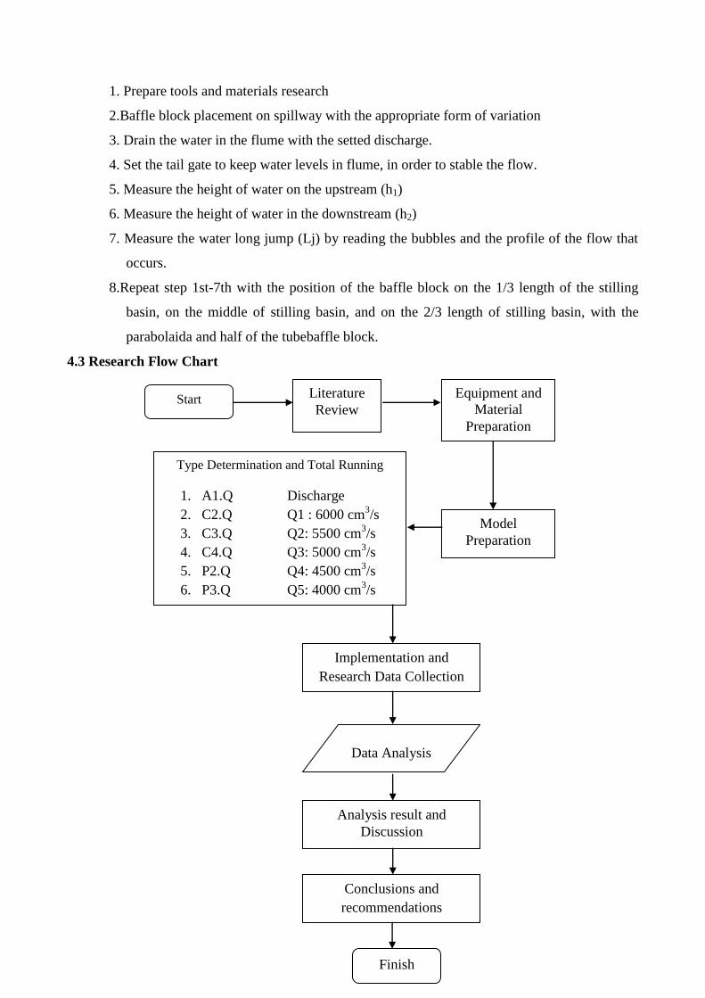
4.3 Research Flow Chart
Start Literature
Review
Equipment and
Material
Preparation
Model
Preparation
Type Determination and Total Running
1. A1.Q Discharge
2. C2.Q Q1 : 6000 cm3/s
3. C3.Q Q2: 5500 cm3/s
4. C4.Q Q3: 5000 cm3/s
5. P2.Q Q4: 4500 cm3/s
6. P3.Q Q5: 4000 cm3/s
7. P4.Q Q6: 3500 cm3/s
Implementation and
Research Data Collection
Data Analysis
Analysis result and
Discussion
Conclusions and
recommendations
Finish

6
Table IV.1 Flow Chart of the Research
5. RESULT AND DISCUSSION
5.1 Testing Result
Discharge tests on the spillway carried by flowing water passing through the flume with six
discharge variations using a water pump. The calculation of the discharge amount is set by opening
the valves regulating discharge at the water pump. The flow rate was measured using the equation
v-notch.
The water depth (h) the flume set such as value the discharge plan (Q). Discharge
determination set such as Vnotch can flowing discharge from the smallest to the largest. Range of
discharge from 3500 cm3/s, until 6000 cm
3/s. In preliminary experiments conducted with steady
uniform flow. The trial found depth of steady uniform flow according with the discharge flow.
Discharge and flow test experimental data conducted at the flume can be seen in full in the
appendix.
5.2 Data Analysis dan Discussion.
Flowing on the stilling basin USBR II was first performed after in steady uniform flow condision.
The analysis conducted on the experimental results in the laboratory include the calculation of
the flow velocity at the upstream spillway (V1), the velocity of the downstream spillway (V2), the
Reynolds number in the downstream stilling basin (Re), the energy loss in the flowing spilway of
the weir until past the stilling basin water (hf ) and the lenght of hydraulic jump (Lj).
5.2.1 Velocity Flow Relationship with Discharge Variation Analysis
The velocity flow in the upstream weir counted from (2x high weir) 40 cm after called (h1), (hd) is
water depth flowing over crest of the weir, while the (d2) is the water depth in the downstream
stilling basin after the hydraulic jump water. A detailed explanation flow depth observation
locations are presented in the following figure.

7
Figure V.1 Velocity Location in the Upstream of the Weir (V1), Flowing the Weir (Vd) and
Downstream Stilling Basin (V2) USBR II
To calculate the velocity flow on the upstream and downstream of the weir using the
following equation. Detailed calculations are presented in Table V.1 below.
Table V.1 Velocity Flow
Seri No Q b h1 h2 hd v1 v2 vd
(cm3/dt) (cm) (cm) (cm) (cm) (cm/dt) (cm/dt) (cm/dt)
A1.Q
1 6000.00 30 25.3 9.6 5.30 7.9051 20.8333 37.7358
2 5500.00 30 25 8.5 4.90 7.3333 21.5686 37.4150
3 5000.00 30 24.5 7.9 4.30 6.8027 21.0970 38.7597
4 4500.00 30 24 7.3 4.00 6.2500 20.5479 37.5000
5 4000.00 30 23.7 6.6 3.60 5.6259 20.2020 37.0370
6 3500.00 30 23.5 6 3.40 4.9645 19.4444 34.3137
(Source : Resech Value)
The water depth at the upstream weir is the greatest depth, because of backwater effect
(such as weirs function is to raise the water level of the river/canal), the flow depth is also raise
when the discharge flowing increase. Flow depth h2 is the water depth after a hydraulic jump of
water. In this condition, the water flow is subcritical, after the water flow is supercritical (when the
water flowing flow through the weir body after going through an top of spillway). Figure V.2 shows
that the water depth in upstream top of weir and downstream stilling basin. That figure show that
the water depth increasing if the discharge greater.
Figure V.2 Relationship Betwen Discharge Variation Q (cm3/dt) with Depth
Flow h (m)
Velocity at the upstream weir is lowest, because occure the reducing followed velocity after
hydraulic jump of water and velocity before hydraulic jump of water is the highest velocity.
Decrease velocity occurs in an stilling basin couse the hydraulic jump the flow characteristic will

8
change from the supercritical to subcritical flow. Events hydraulic jump of water is also reduced the
energy flow, so that energy flow after the hydraulic jump water is relatively lower. Information
water velocity in the upstream weir, discharge and velocity after hydraulic jump of water is
presented, in Figure V.3.
Figure V.3 Relationship Betwen Discharge Variation Q (cm3/dt) with
velocity Flow v (cm/dt).
5.2.2 Reynolds Numbers Relationship with Discharge Variations Analysis
To calculate Reynolds number in the downstream stilling basin using equation (III.5). With an
average water temperature 25C then value equal to 0,0089 cm2/s.
Table V.2 Reynolds Number Downstream Stilling Basin.
b h1 h2 hd v1 v2 vd Re
(cm) (cm) (cm) (cm) (cm/dt) (cm/dt) (cm/dt)
30 25.3 9.6 5.3 7.90514 20.8333 37.7358 5199.32
30 25 8.5 4.9 7.33333 21.5686 37.415 4470.48
30 24.5 7.9 4.3 6.80272 21.097 38.7597 3955.26
30 24 7.3 4 6.25 20.5479 37.5 3448.25
30 23.7 6.6 3.6 5.62588 20.202 37.037 2897.22
30 23.5 6 3.4 4.96454 19.4444 34.3137 2390.63

9
Figure V.4 Relationship Discharge Variation (cm
3/s) with Reynolds Number
Figure V.4 shows the relationship between discharge variations with the Reynolds number.
Reynolds Numbers at Open channel flow is based on three condition, Laminar having a Reynolds
Numbers (Re) <500, turbulent Re> 1000, and between 500-1000 is a transition flow. Figure V.4
can be seen that all of the flow that occurred on all treatments are turbulent flow, because it has a
Reynolds number (Re)> 1000. Really relations of discharge variation (cm3/sec) with the Reynolds
number can already be seen in the discussion of the relationship between discharge variations
(cm3/sec) with a downstream hydraulic jump velocity (cm/sec). Because the greater velocity in the
downstream stilling basin in this research for kinematic viscosity is equal in all flows.From the
figure also seen increasing discharge flow, the Reynolds number in the downstream stilling basin
getting bigger.
5.2.3 Energy Loss Relationship with the Discharge Variation Analysis
Stilling basin made to reduced the energy, the greater energy loss in channel means the best energy
reduction. Energy loss in spillway of the weir flows through until past the stilling basin water is the
result of the energy calculation in the weir upstream minus energy at the end of stilling basin. This
is done because the authors difficult to count energy loss of water flow in the stilling basin. To
calculate the height of the energy flow in the upstream and downstream stilling basin using equation
V.3.
The shape and placement of the baffle block on an stilling basin most effective to reduce
energy from the reserch, as follows:

10
1. In the greatest discharge variation 6000 cm3/s (Q) occure large loss energy, and the smaller
discharge variation 3500 cm3/s (Q) water flow in the flume get the smaller number energy
loss that occurs.
2. Baffle blocks performance to reduce energy is increase, cause the momentum of flow in the
begining stilling basin higher than placement another.
3. Parabolaida baffle block effectively reduced energy than another, couse the shape from the
parabolaida can be reduce from the flowing of energy of water.
Baffle blocks placement an effective reduced the energy flow is a baffles block series C2.Q
and P2.Q. Than placement baffle block serially C2.Q, P2.Q, C3.Q, P3.Q, C4.Q, P4.Q, and A1.Q.
5.2.4 Lenght of Hydraulic Jump Water Relationship with Discharge Analysis.
The length of the hydraulic jump (Lj) measured from the frist of hydraulic jump to the longgest
point of the hydraulic jump of water. The relationship between water discharge with a lenght of
hydraulic jump can be seen in (Figure V.7), shows that the increasing flow rate, the greater the
lenght of hydraulic jump water. The figure also shows the baffle block placement at the end of an
stilling basin most effective for reducing the length of the water jump. Form baffle blocks on an
stilling basin best to reduce the length of the water jump is due to the shorter stepping P4.Q water
then energy reduction, the better, for the baffle block placement P4.Q produce lenght of hydraulic
jump most water-short.
Figure V.8 Relationship Discharge Variation (cm3/s) with Lenght of Hydraulic Jump Water(cm)

11
The shape and palcement of the baffle block seri on an stilling basin most effective to reduce
lenght of hydraulic jump from the reserch, as follows:
1. In the greatest discharge variation 6000 cm3/s (Q) occure large lenght of hydraulic jump,
and the smaller discharge variation 3500 cm3/s (Q) water flow in the flume get the smaller
number lenght of hydraulic jump that occurs.
2. Baffle blocks performance lenght of hydraulic jump is increase, cause the momentum
lenght of hydraulic jump of flow in the begining stilling basin higher than placement
another.
3. Parabolaida baffle block effectively reduced lenght of hydraulic jump than another, couse
the shape from the parabolaida can be reduce from the flowing of hydraulic jump of water.
Table V.3 Length of Hydraulic Jump Correction Water with Energy Loss.
No Baffle block
postition hf on E1 (%)
Lj on Lj without
baffle block (%) Chek
1 A1.Q 68.71% 0.00% 0.00%
2 C2.Q 73.26% 25.11% 18.39%
3 C3.Q 70.02% 24.13% 16.90%
4 C4.Q 68.70% 40.24% 27.65%
5 P2.Q 73.19% 26.75% 19.58%
6 P3.Q 70.13% 32.13% 22.53%
7 P4.Q 69.42% 49.28% 34.21%
From table V3 correction hydraulic water jump with a energy loss, then the performance of the
most effective baffle block of reduced energy flow and reduces the length of the hydraulic water
jump is P4.Q position (with performance 34.21%), which baffle block parabolaida with the form at
the end stilling basin placement. Because velocity flow is large relative (cause pressure from the
momentum of flow in the beginner placement is bigger than another). Than placement baffle block
serially P4.Q, C4.Q, P3.Q, C3.Q, P2.Q, C2.Q, and A1.Q.
6. CONCLUSION AND RECOMMENDATIONS
6.1 Conclusion
Based on research data analysis and discussion, can conclude as follows:

12
1. The order baffle block performance effectively to reduce energy flow is half tube baffle
block in the beginning stilling basin, available for all of the discharge (Seri C2.Q). Than
placement baffle block serially C2.Q, P2.Q, C3.Q, P3.Q, C4.Q, P4.Q, and A1.Q.
2. The order baffle block performance effectively to reduce length jump of water is
parabolaida baffle block with position in the end of stilling basin, available for all discharge
value (Seri P4.Q). Then placement baffle block serially P4.Q, C4.Q, P3.Q, C3.Q, P2.Q,
C2.Q, and A1.Q.
3. Shaped and position performance effectively baffle block for reduce energy and reduce
length hydraulic jump of water is parabolaida baffle block with the position in the end of the
stilling basin, available for all discharge value (Seri P4.Q). Then P4.Q, C4.Q, P3.Q, C3.Q,
P2.Q, C2.Q, and A1.Q.
6.2 Recommendations
Recommendation that can be given with the value on this research following as:
1. For the next research can do with the variation shape of baffle block and slope of the
spillway in the downstream of the weir diverse and use variation height of the weir.
2. For the next research additional about the scour in the downstream hydraulic jump of water
3. For the next research can do the variation slope of the flow
4. For the next research temperature effect (kinematic viscosity) can be considered.
BIBLIOGRAPHY
Anggrahaini. 1997. Hidrolika Saluran Terbuka. Surabaya: CV Citra Media.
Anonim. 2001. Pedoman Penyusunan “Laporan Tugas Akhir”. Surakarta: Jurusan Teknik Sipil
Fakultas Teknik Universitas Muhammadiyah Surakarta.
Anonim. 1986. Standar Perencanaan Irigasi. Kriteria Perencanaan Bagian Bangunan Utama KP-
02. Jakarta: Yayasan Badan Penerbit Pekerjaan Umum.
Anonim. 2014. Module 4 Hydraulic Structures for Flow Diversion and Storage.
http://nptel.iitm.ac.in/courses/Webcourse-
contents/IIT%20Kharagpur/Water%20Resource%20Engg/pdf/m4l08.pdf, IITM, Kharagpur,
Diakses 25 Oktober 2014.
Ardian, P.W. 2014. “Pengaruh Variasi Kemiringan Tubuh Hilir Spilway dan Penempatan Baffle
Blocks Pada Kolam Olak Tipe Trajectory Bucket Terhadap Loncatan Hidrolis dan
Peredaman Energi.” Skripsi (not publish). Surakarta: Universitas Muhammadiyah
Surakarta.
Chow, V.T. 1985. Hidrolika Saluran Terbuka. Jakarta: Erlangga.
Nurrizal, Dwi Setyo 2015. Pengaruh Penempatan Baffle Blocks Tipe Cekung Setengah Lingkaran
Dan Parabolik Pada Bendung Dengan Kolam Olak Tipe Solid Roller Bucket Terhadap

13
Panjang Loncat Air Dan Kehilangan Energi. Skripsi thesis, Universitas Muhammadiyah
Surakarta.
Pembra, J.A. 2013. “Pengaruh Variasi Kemiringan Tubuh Hilir Bendung dan Penempatan Baffle
Blocks pada Kolam Olak Tipe Solid Roller Bucket Terhadap Loncatan Hidrolis dan
Peredaman Energi.” Skripsi (not publish). Surakarta: Universitas Muhammadiyah
Surakarta.
Peterka, A.J. 1974. Hydraulics Design Of Stilling Basin And Energy Disipaters. Colorado: United
States Department Of Interior, Bureau Of Reclamation, Denver.
Triatmodjo, B. 1995. Hidraulika II. Yogyakarta: Beta Offset.