Embed Size (px)
Citation preview
Parabolic Curve fitting as an 3D Trajectory Estimation of the Soccer Ball
Kyuhyoung Choi and Yongduek Seo
Sogang University, {Kyu, Yndk}@sogang.ac.kr
Abstract A soccer ball is projected to an image as a small whitish round blob. With multiplesynchronized views, its 3D position can be estimated. In this paper, the ball trajectory ismodeled as a sequence of 3D parabolic(ballistic) curves from multiple views. With this trajectoryestimation method, lossless tracking is guaranteed for pretty long video clips as shown in ourexperiments.
1 Introduction
The most difficulty in visual tracking of soccer ballcomes from its size. Its small size with fast motionmakes its features useless becoming small whitishand noisy ellipse which makes it hard to keep track-ing the ball without aid of noise removal [1, 2]. An-other difficulty is from its interaction with playerswhich makes it generally accepted that ball trackinghas two modes of status, that is, visible and invisi-ble. During visible mode, it shows ballistic motionof elastic sphere while it is occluded by players andhardly separated as independent image blob duringthe other mode. So tracking ball becomes findingthe trajectory for each visible mode. For extractionof 2D ball trajectory, [3] used triplet seeds grow-ing to trajectory candidates. One of the candidatesbest satisfying constant acceleration model is se-lected as the trajectory for the segment. However,constant acceleration in 2D does not mean any ofthe ball’s physics though it is the best choice. In oursetting, we use 3D ball trajectory as an 3D paraboliccurve with the acceleration of gravity. Some land-marks on the pitch gives clues to reconstruct 3Dinformation which leads to 3D ball tracking [4]. Ifthe ball can be viewed from the multiple cameras,ideally the 3D rays from each camera centers willmeet at one point which is the center of the ball.However, this can be applied to clutters too. Wehave to exclude less probable 3D points(clutters)one by one until we get the most probable one(true3D ball point). This can be done by evaluating theconsistency of a sequence of 3D points. As applica-tions, 3D tracking results can be further processedto lead to enriched broadcast and game analysis [5].The purpose of our trajectory estimation approachis to achieve lossless tracking given a batch of longvideo sequence such as a half soccer match. Therest of this paper is organized as following: Section 2
deals with our soccer tracking environment and pre-image processing. The ball trajectory extraction al-gorithm is discussed in Section 3. Section 4 providesexperimental results and finally Section 5 concludesthis paper.
2 Getting Observation Data
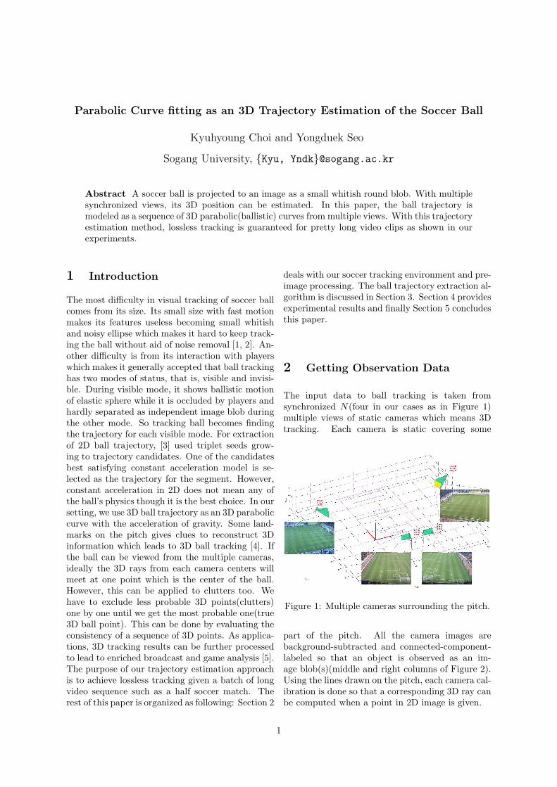
The input data to ball tracking is taken fromsynchronized N(four in our cases as in Figure 1)multiple views of static cameras which means 3Dtracking. Each camera is static covering some
Figure 1: Multiple cameras surrounding the pitch.
part of the pitch. All the camera images arebackground-subtracted and connected-component-labeled so that an object is observed as an im-age blob(s)(middle and right columns of Figure 2).Using the lines drawn on the pitch, each camera cal-ibration is done so that a corresponding 3D ray canbe computed when a point in 2D image is given.
1
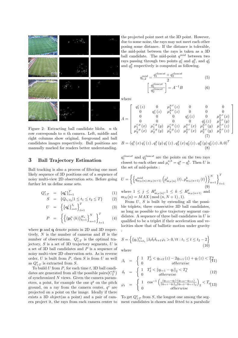
Figure 2: Extracting ball candidate blobs. n throw corresponds to n th camera. Left, middle andright columns show original, foreground and ballcandidates images respectively. Ball positions aremanually marked for readers better understanding.
3 Ball Trajectory Estimation
Ball tracking is also a process of filtering one mostlikely sequence of 3D positions out of a sequence ofnoisy multi-view 2D observation sets. Before goingfurther let us define some sets.
Q∗1:T = {q∗t }Tt=1 (1)
S = {Qt1:t2 |1 ≤ t1 ≤ t2 ≤ T} (2)
U ={{
qit
}It
i=1
}T
t=1(3)
P ={{
{pnt (h)}Hn
h=1
}N
n=1
}T
t=1
(4)
where p and q denote points in 2D and 3D respec-tively, N is the number of cameras and H is thenumber of observations. Q∗1:T is the optimal tra-jectory, S is a set of 3D trajectory segments, U isa set of 3D ball candidates and P is a sequence ofnoisy multi-view 2D observation sets. As in reverseorder, U is built from P , then S is from U as wellas Q∗1:T is extracted from S.
To build U from P , for each time t, 3D ball candi-dates are generated from all the possible pairs
(CN
2
)of synchronized N views. Given the camera param-eters, a point, for example the one qg on the pitchground, on a ray from the camera center, qc areprojected on a point on the image. Ideally if thereexists a 3D object(as a point) and a pair of cam-era project it, the rays from each camera center to
the projected point meet at the 3D point. However,due to some noise, the rays may not meet each otherposing some distance. If the distance is tolerable,the mid-point between the rays is taken as a 3Dball candidate. The mid-point qmid between tworays passing through two points qc
1 and qg1 , and qc
2
and qg2 respectively is computed as following.
qmid1,2 =
qclosest1 + qclosest
2
2(5)
[qclosest1
qclosest2
]= A−1B (6)
where
A =
qc1 (z) 0 µg,c
1 (z) 0 0 00 qc
1 (z) µg,c1 (z) 0 0 0
0 0 0 qc2 (z) 0 µg,c
2 (x)0 0 0 0 qc
2 (z) µg,c2 (y)
µc,g1 (x) µc,g
1 (y) µc,g1 (z) µg,c
1 (x) µg,c1 (y) µg,c
1 (z)µc,g
2 (x) µc,g2 (y) µc,g
2 (z) µg,c2 (x) µg,c
2 (y) µg,c2 (z)
(7)
B = (qg1 (x) qc
1 (z) , qg1 (y) qc
1 (z) , qg2 (x) qc
2 (z) , qg2 (y) qc
2 (z) , 0, 0)T
(8)
qclosest1 and qclosest
2 are the points on the two raysclosest to each other and µa,b
i = qai − qb
i . Then U isthe set of mid-points :
U ={{
qmidmN (n),mN (n+1)
(pjmN (n) (t) , pk
mN (n+1) (t))}N
n=1
}T
t=1(9)
where 1 ≤ j ≤ HtmN (n), 1 ≤ k ≤ Ht
mN (n+1) andmN (n) = MAX (mod (n,N + 1) , 1).
From U , S is built by extending all the possi-ble triplets, three consecutive 3D ball candidates,as long as possible to give trajectory segment can-didates. A sequence of three ball candidates in U isqualified to be a triplet if their acceleration and ve-locities show that of ballistic motion under gravity:
S ={{qt}t2
t=t1|βtδtδt+1ϕt > 0,∀t : t1 ≤ t ≤ t2 − 2
}
(10)where
βt ={
1 T lβ < qt+2 (z)− 2qt+1 (z) + qt (z) < Tu
β
0 otherwise(11)
δt ={
1 T lδ < ‖qt+1 − qt‖2 < Tu
δ
0 otherwise(12)
ϕt =
{1 cos−1
((qt+1−qt)·(qt+2−qt+1)‖qt+1−qt‖2‖qt+2−qt+1‖2
)2
< Tϕ
0 otherwise(13)
To get Q∗1:T from S, the longest one among the seg-ment candidates is chosen and fitted to a parabolic
curve parameterized by Θ.
Θ = {a, b, c, d, e, f, g|qt (x) = at + b, qt (y) = cq (x) + d,
qt (z) = eq (x)2 + fq (x) + g}(14)
The nearest segments to the both ends of thelongest are merged into the longest if its fitness tothe curve is tolerable, then the curve is updated con-sidering the new support. After iterations as shownin Algorithm 1, is estimated a parabolic represen-tative of the ball motion for a certain period bothends of which correspond to the points where the3D curve meets the pitch ground. Since the coeffi-cients of 3D parabolic curve equation is estimatedQ∗1:T is a function of time.
Algorithm 1 Growing a sequence of 3D points sup-porting a 3D parabolic curveRequire:{q}S = arg max
{qt}jt=i∈S
(j − i)
Equation 14Ensure:
AreOverlapped(a, b) returns T (true) if the se-quences a and b are temporally overlapped.AreConsistent(a, b) returns T if the sequences aand b are qualified to be parts of the same se-quence.while isChanged = T and isOutOfRange = Fdo
isChanged := FisOutOfRange := Ffor i, {q}i ∈ S do
if AreOverlapped({q}i, {q}S) = T andAreConsistent({q}i, {q}S) = T then{q}S := {q}S ∪ {q}i
ΘS := arg maxΘ
p ({q}S |Θ)
isChanged := Tif S = ∅ or qS
1 (z) ≤ 0 and qS|{q}S | (z) ≤ 0
thenisOutOfRange := T
end ifbreak
end ifend for
end while
4 Experiments
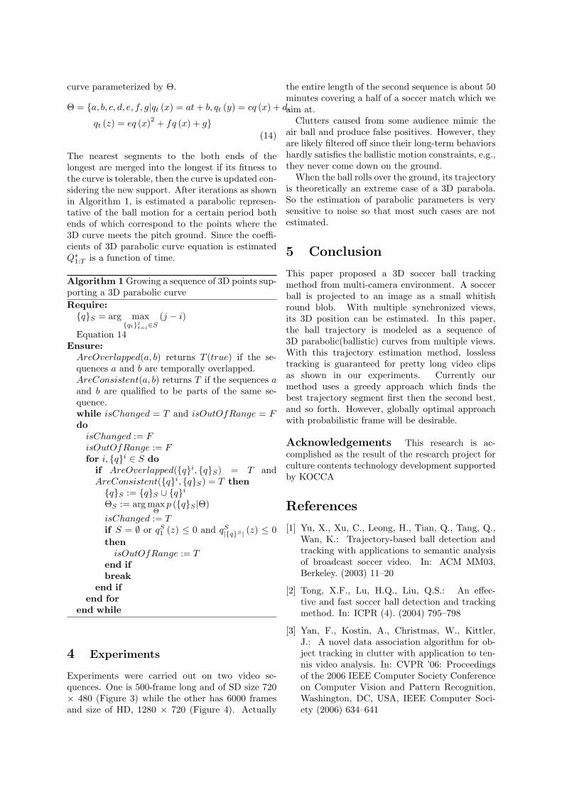
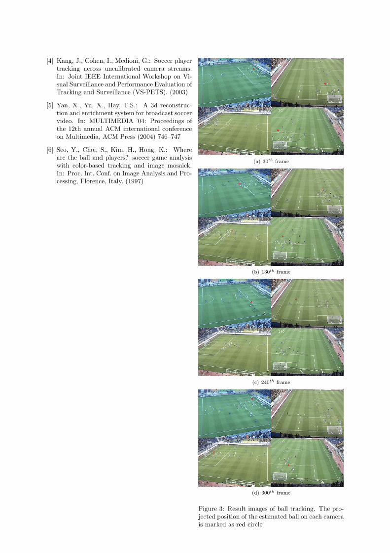
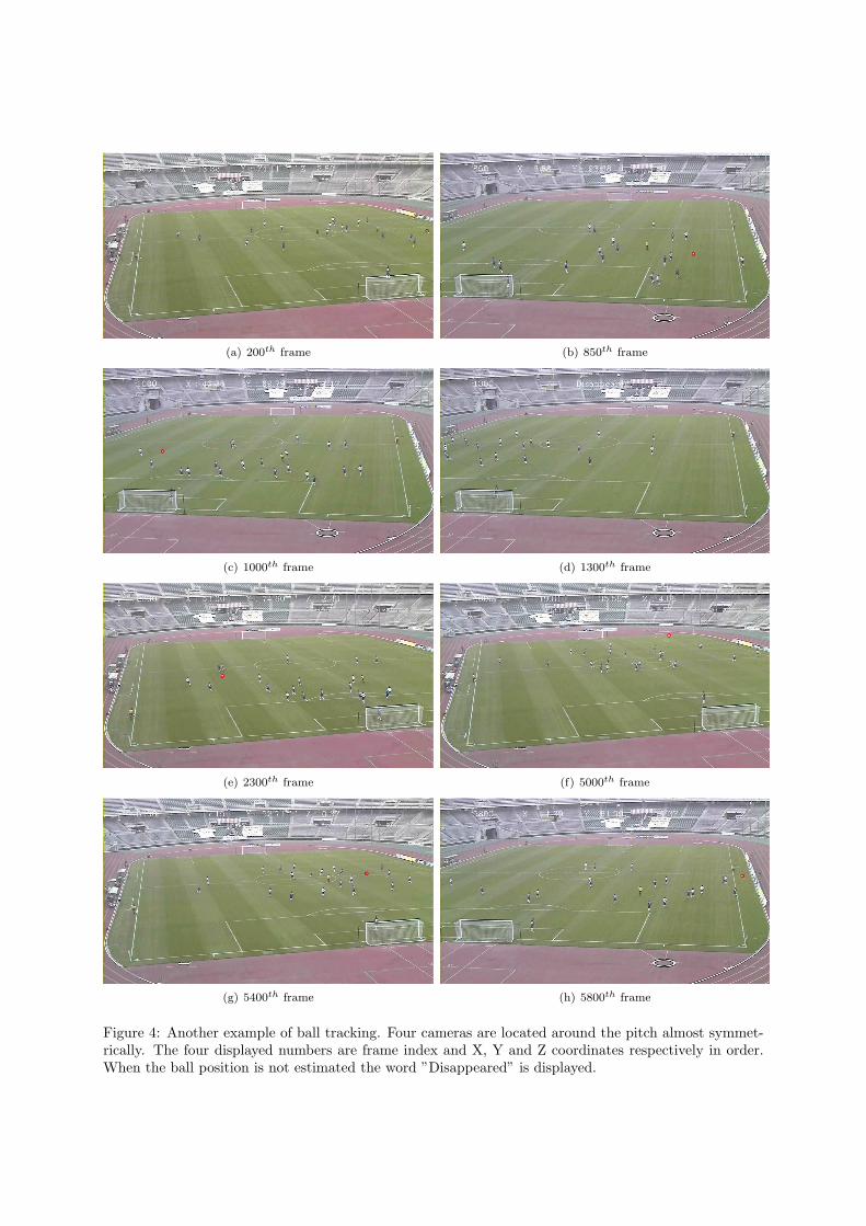
Experiments were carried out on two video se-quences. One is 500-frame long and of SD size 720× 480 (Figure 3) while the other has 6000 framesand size of HD, 1280 × 720 (Figure 4). Actually
the entire length of the second sequence is about 50minutes covering a half of a soccer match which weaim at.
Clutters caused from some audience mimic theair ball and produce false positives. However, theyare likely filtered off since their long-term behaviorshardly satisfies the ballistic motion constraints, e.g.,they never come down on the ground.
When the ball rolls over the ground, its trajectoryis theoretically an extreme case of a 3D parabola.So the estimation of parabolic parameters is verysensitive to noise so that most such cases are notestimated.
5 Conclusion
This paper proposed a 3D soccer ball trackingmethod from multi-camera environment. A soccerball is projected to an image as a small whitishround blob. With multiple synchronized views,its 3D position can be estimated. In this paper,the ball trajectory is modeled as a sequence of3D parabolic(ballistic) curves from multiple views.With this trajectory estimation method, losslesstracking is guaranteed for pretty long video clipsas shown in our experiments. Currently ourmethod uses a greedy approach which finds thebest trajectory segment first then the second best,and so forth. However, globally optimal approachwith probabilistic frame will be desirable.
Acknowledgements This research is ac-complished as the result of the research project forculture contents technology development supportedby KOCCA
References
[1] Yu, X., Xu, C., Leong, H., Tian, Q., Tang, Q.,Wan, K.: Trajectory-based ball detection andtracking with applications to semantic analysisof broadcast soccer video. In: ACM MM03,Berkeley. (2003) 11–20
[2] Tong, X.F., Lu, H.Q., Liu, Q.S.: An effec-tive and fast soccer ball detection and trackingmethod. In: ICPR (4). (2004) 795–798
[3] Yan, F., Kostin, A., Christmas, W., Kittler,J.: A novel data association algorithm for ob-ject tracking in clutter with application to ten-nis video analysis. In: CVPR ’06: Proceedingsof the 2006 IEEE Computer Society Conferenceon Computer Vision and Pattern Recognition,Washington, DC, USA, IEEE Computer Soci-ety (2006) 634–641
[4] Kang, J., Cohen, I., Medioni, G.: Soccer playertracking across uncalibrated camera streams.In: Joint IEEE International Workshop on Vi-sual Surveillance and Performance Evaluation ofTracking and Surveillance (VS-PETS). (2003)
[5] Yan, X., Yu, X., Hay, T.S.: A 3d reconstruc-tion and enrichment system for broadcast soccervideo. In: MULTIMEDIA ’04: Proceedings ofthe 12th annual ACM international conferenceon Multimedia, ACM Press (2004) 746–747
[6] Seo, Y., Choi, S., Kim, H., Hong, K.: Whereare the ball and players? soccer game analysiswith color-based tracking and image mosaick.In: Proc. Int. Conf. on Image Analysis and Pro-cessing, Florence, Italy. (1997)
(a) 30th frame
(b) 130th frame
(c) 240th frame
(d) 300th frame
Figure 3: Result images of ball tracking. The pro-jected position of the estimated ball on each camerais marked as red circle
(a) 200th frame (b) 850th frame
(c) 1000th frame (d) 1300th frame
(e) 2300th frame (f) 5000th frame
(g) 5400th frame (h) 5800th frame
Figure 4: Another example of ball tracking. Four cameras are located around the pitch almost symmet-rically. The four displayed numbers are frame index and X, Y and Z coordinates respectively in order.When the ball position is not estimated the word ”Disappeared” is displayed.