Embed Size (px)
Citation preview

Appendix A - Life cycle inventory
Structures and improvements
The structures and improvements of the solar tower power plant include the clearing of the power
plant site of all vegetation prior to site work, the building of a road infrastructure at the power plant
site and the fencing of the area. The yard piping necessary to ensure drainage, domestic water, piping
for fire protection, primary water treatment, raw water and sanitary sewer accounts for 5.2 km and
requires excavation and backfill during installation. Additionally the basic structure at the power plant
site comprises maintenance and warehouse buildings, control and administration buildings, a water
treatment facility, the turbine generator control building, the cooling tower control building and the
gatehouse. During operation of the power plant the occupation of industrial area is considered. For the
end of life of this section it is assumed that the piping system stays in ground, whereas dismantling
LCA data for all other processes was found in the ecoinvent database and can be obtained from Table
A.1.
Table A.1 Process and material demand for the section “Structures and Improvements” and
corresponding LCA datasetsLife cycle phase Component Material/Process Corresponding LCA process Value Unit
Manufacturing Site Improvements Clearing of power plant site Transformation, to industrial area, RER 12.5 [km²]
Site Improvements Road infrastructure road, CH 423.6 [km∙a]
Site Improvements Site fences wire drawing, steel, RER 36.4 [t]
steel, converter, unalloyed, at plant,
RER 36.4 [t]
Piping
Yard piping (domestic water,
fire protection, primary water
treatment, raw water, sanitary
sewer and drains water supply network, CH 5.2 [km]
Piping Yard Piping - Excavation excavation, hydraulic digger, RER 11468 [m³]
Piping Yard Piping - Back Fill excavation, hydraulic digger, RER 11468 [m³]
Buildings Buildings building, hall, steel construction, CH 2411 [m²]
Use phase
Occupation of power plant
site Occupation, industrial area, RER 319.4 [km²∙a]
End of life Disposal road infrastructure disposal, road, RER 423.6 [km∙a]
Recycling “Structures and
Improvements”
disposal, building, reinforcement steel,
to recycling, CH 12.8 [t]
Disposal “Structures and
Improvements”
disposal, building, reinforcement steel,
to final disposal, CH 23.7 [t]
Collector systems
1
1
2
3
4
5
6
7
8
9
10
11
12
13
14
1516
1718
19

The LCI datasets of the three heliostat concepts include processes which describe the life cycle of
the heliostat, the main wiring, the subordinate wiring, the transformers, the emergency generators, the
components of the autonomous solar heliostat systems, the operational and maintenance efforts, the
transport services and the disposal services.
The heliostat is modelled based on the weight of steel per aperture area reported as 10.18 kg/m2 of
aperture area (von Reeken, 2015). LCI -data on gear drives is obtained from technical datasets of the
manufacturers of slew gear units (AUMA, 2016; GFC, 2012). The mass of motors and control units
are estimated by extrapolating the values given in Kolb et al. (2007) based on the aperture area of the
heliostat. The material demand for mirrors is calculated from the geometry of the LH2.3 Brightsource
heliostat reflector and the specific density of glass mirrors (2430 kg/m3) (Koretz, 2014). The
connection between the steel structure and the reflective mirrors is achieved by an industrial adhesive
tape along six vertical supporting arms. Data on weight and composition of the adhesive tape is
derived from technical datasheets (3M, 2004). It is assumed that the width of the adhesive tape is
40 mm, whereas the length per heliostat equals the length of the six cantilever arms. The concrete
foundation of the heliostat is cylindrical and its mass is dimensioned according to the investigated
reflector area, extrapolated from the foundation of the Abengoa 66 heliostat (Weinrebe, 2000).
Moreover, the excavation of the foundation holes and the welding of the steel structure (1.3 m welding
per heliostat) are considered (Kolb et al., 2007).
The conventional wiring concept can be divided into main field wiring and subordinate field wiring
consisting of two-core copper cables with polyvinyl chloride (PVC) insulation. For main field wiring
and the subordinate field wiring copper cable dimensions of 2x10re (re = round-solid core) and 2x4re
are used (Lapp Kabel, 2016). The total masses of copper and PVC are calculated based on required
length of main field wiring and subordinate wiring in section Error: Reference source not found. The
wiring processes include standard LCA processes for the manufacturing of cables and the extrusion of
PVC pipes.
To operate the heliostat field continuously and to ensure system reliability auxiliary systems are
needed, which were originally allocated to the inventory list of the EPGS of (Kelly et al., 2010). These
auxiliary systems comprise three 1.0/1,12 MVA 13.8 kV/480 V load centre transformers and three
1 MW diesel emergency generators. To electrify the heliostats in the conventional field design two
2.5 MVA load centre transformers are used. The transformer LCI data is derived by creating a
parameterised dataset from EPDs of the transformer manufacturer ABB (ABB, 2003a, 2003b, 2003c,
2003d, 2003e, 2003f, 2003g).
The electricity supply of the investigated autonomous solar heliostat concepts is modelled by a
standard LCI dataset of a photovoltaic panel according to (Ecoinvent, 2010).
The battery systems are analysed by using the LCI datasets on LiFPO4 batteries and LiNMC
batteries reported in Majeau-Bettez et al. (2011a, 2011b). Based on the energy density of the total
2
1
2
3
4
5
6
7
8
9
10
11
12
13
14
15
16
17
18
19
20
21
22
23
24
25
26
27
28
29
30
31
32
33
34
35
36

battery packs (88 Wh/kg and 112 Wh/kg of LiFPO4 and LiNMC, respectively) and the battery
capacities investigated in this study, an adjusted LCI dataset of the two battery systems is generated.
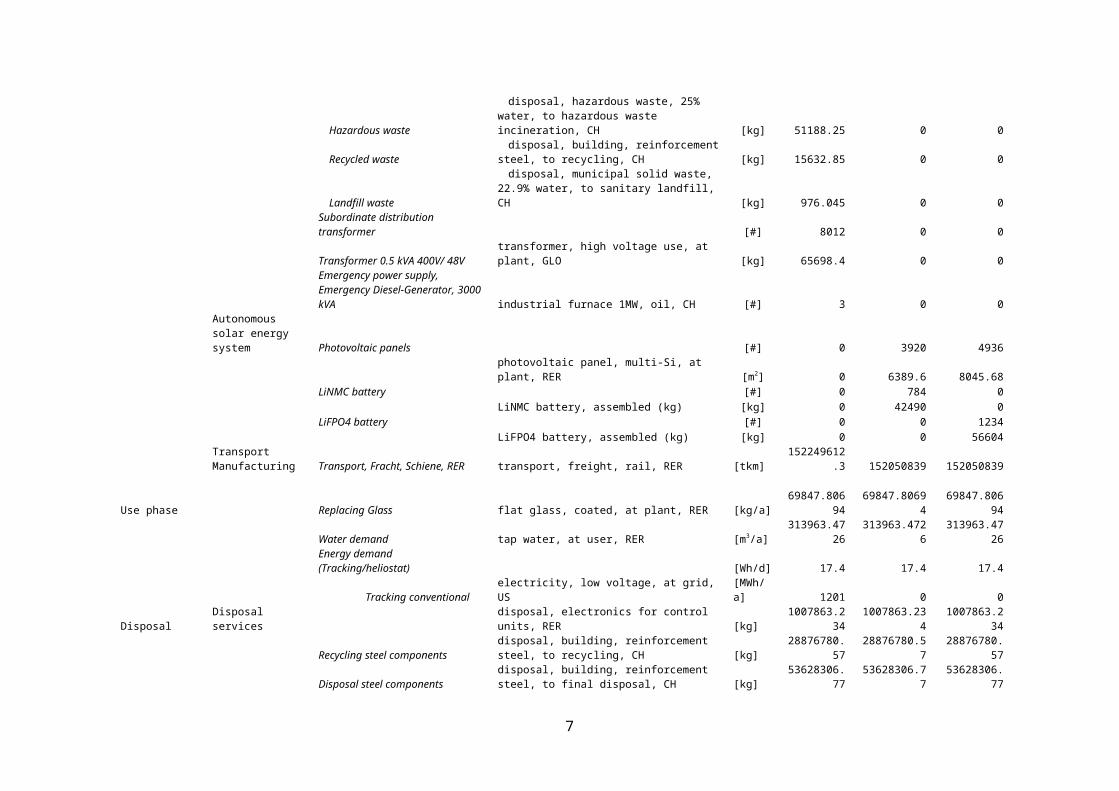
Operational demands during the use phase of the plants life cycle encompass the replacing of
reflector glass (0.1% of aperture area per year), the water demand (0.044 m³ per m² aperture area and
year) for cleaning the reflectors and the calculated energy demand for tracking (Turchi and Heath,
2013; Viebahn et al., 2008).
Additional end-of-life transport processes are modelled for LCA processes which do not include
transport to disposal.
3
1
2
3
4
5
6
7
8

Table A.2 Process and material demand for the three investigated collector concepts and used LCA datasets
Life cycle phase Part of system Components Corresponding LCA process unit
Solar collector field with
conventional energy supply
Solar collector field with
autonomous solar energy supply (a)
Solar collector field
with autonomous solar energy supply (b)
Manufacturing HeliostatStructural steel (Pylon, Torque Tube, supports) reinforcing steel, at plant, RER [kg] 73145674.18 73145674.18 73145674.18Gear drives (slew gear units) reinforcing steel, at plant, RER [kg] 9359413.16 9359413.16 9359413.16Motors & Controls (Steel, Copper) electronics for control units, RER [kg] 1007863.234 1007863.234 1007863.234Glass mirrors flat glass, coated, at plant, RER [kg] 69847806.94 69847806.94 69847806.94Adhesives adhesive for metals, at plant, DE [kg] 207333.4 207333.4 207333.4Foundation (concrete) concrete, normal, at plant, CH [m3] 190517.5475 190517.5475 190517.5475Excavation/drilling of holes excavation, hydraulic digger, RER [m3] 190517.5475 190517.5475 190517.5475Welding (20min =10m) welding, arc, steel, RER [m] 488295 488295 488295
WiringMain wiring Field wiring (copper) copper, at regional storage, RER [kg] 662577.60 0 0
Field wiring (wire drawing) wire drawing, copper, RER [kg] 662577.60 0 0PVC Coating/Insulation polyethylene, HDPE, granulate, at plant, RER [kg] 1076212.57 0 0Extrusion of insulation extrusion, plastic pipes, RER [kg] 1076212.57 0.00 0.00
Subordinate wiring Field wiring (copper) copper, at regional storage, RER [kg] 72216.32 72216.32 72216.32
Field wiring (wire drawing) wire drawing, copper, RER [kg] 72216.32 72216.32 72216.32PVC Coating/Insulation polyethylene, HDPE, granulate, at plant, RER [kg] 206764.83 206764.83 206764.83Extrusion of insulation extrusion, plastic pipes, RER [kg] 206764.83 206764.83 206764.83
Auxiliary systems Load Center Transformer - 12kV / 400 V, 2.5 MVA [#] 2 0 0Electrical steel, steel sheet, steel
profiles/construction steel reinforcing steel, at plant, RER [kg] 21671.60625 0 0Glass fiber glass fibre, at plant, RER [kg] 978.8805 0 0Kraft paper kraft paper, unbleached, at plant, RER [kg] 931.7395 0 0Copper wire wire drawing, copper, RER [kg] 10008.10125 0 0
copper, at regional storage, RER [kg] 10008.10125Presspan/ Wood particle board, cement bonded, at plant, RER [m3] 0.6922 0 0Porcelain ceramic tiles, at regional storage, CH [kg] 10531.6225 0 0Aluminium aluminium, primary, at plant, RER [kg] 282.46925 0 0Paint alkyd paint, white, 60% in solvent, at plant, RER [kg] 376.0565 0 0Transformer oil silicone product, at plant, RER [kg] 10531.6225 0 0Resin polyurethane, rigid foam, at plant, RER [kg] 0 0 0
4
12

Red brass brass, at plant, CH [kg] 0 0 0Insulation material expanded perlite, at plant, CH [kg] 934.89 0 0Silver silver, at regional storage, RER [kg] 0 0 0Electrical energy electricity mix, CH [kWh] 0 0 0Heat energy heat, unspecific, in chemical plant, RER [kWh] 0 0 0
Hazardous wastedisposal, hazardous waste, 25% water, to
hazardous waste incineration, CH [kg] 690.02 0 0
Regular Waste (incl. Waste water)disposal, municipal solid waste, 22.9% water, to
municipal incineration, CH [kg] 1765758 0 0Energy losses [kWh] 0 0 0
Hazardous wastedisposal, hazardous waste, 25% water, to
hazardous waste incineration, CH [kg] 1765758 0 0
Regular Waste (incl. Waste water)disposal, municipal solid waste, 22.9% water, to
municipal incineration, CH [kg] 690.02 0 0
Hazardous wastedisposal, hazardous waste, 25% water, to
hazardous waste incineration, CH [kg] 51188.25 0 0
Recycled wastedisposal, building, reinforcement steel, to
recycling, CH [kg] 15632.85 0 0
Landfill wastedisposal, municipal solid waste, 22.9% water, to
sanitary landfill, CH [kg] 976.045 0 0Subordinate distribution transformer [#] 8012 0 0Transformer 0.5 kVA 400V/ 48V transformer, high voltage use, at plant, GLO [kg] 65698.4 0 0Emergency power supply, Emergency Diesel-Generator, 3000 kVA industrial furnace 1MW, oil, CH [#] 3 0 0
Autonomous solar energy system Photovoltaic panels [#] 0 3920 4936
photovoltaic panel, multi-Si, at plant, RER [m2] 0 6389.6 8045.68LiNMC battery [#] 0 784 0
LiNMC battery, assembled (kg) [kg] 0 42490 0LiFPO4 battery [#] 0 0 1234
LiFPO4 battery, assembled (kg) [kg] 0 0 56604Transport Manufacturing Transport, Fracht, Schiene, RER transport, freight, rail, RER [tkm] 152249612.3 152050839 152050839
Use phase Replacing Glass flat glass, coated, at plant, RER [kg/a] 69847.80694 69847.80694 69847.80694Water demand tap water, at user, RER [m3/a] 313963.4726 313963.4726 313963.4726Energy demand (Tracking/heliostat) [Wh/d] 17.4 17.4 17.4
Tracking conventional electricity, low voltage, at grid, US[MWh/a] 1201 0 0
Disposal Disposal services disposal, electronics for control units, RER [kg] 1007863.234 1007863.234 1007863.234
Recycling steel componentsdisposal, building, reinforcement steel, to recycling, CH [kg] 28876780.57 28876780.57 28876780.57
Disposal steel componentsdisposal, building, reinforcement steel, to final disposal, CH [kg] 53628306.77 53628306.77 53628306.77
Disposal concrete components disposal, building, concrete, not reinforced, to final [kg] 419138604.5 419138604.5 419138604.5
5

disposal, CH
Disposal copper componentsdisposal, copper, 0% water, to municipal incineration, CH [kg] 734793.92 72216.32 72216.32
Transport Disposal Transport services [tkm] 220438.176 34411.9544 38646.1608
6
1
Receiver system
In the receiver system pumps are used to pump the heat transfer fluid (‘cold’ salt at 292°C) to the
receiver, which is located at the top of the solar tower. Each of the two receiver systems is fed by three
pumps with a power capacity of 3.4 MW capable to deliver 1380 m3/h of molten salt. Additionally the
power plant is equipped with a spare pump at a rated capacity of 1.9 MW. Inventory data for all inputs
of process pumping devices were found in the environmental product declarations (EPD) of the pump
manufacturer Sulzer (Sulzer, 2012a, 2012b, 2012c, 2012d, 2012e, 2012f, 2012g, 2012h, 2012i, 2012j,
2012k). These datasets were used to create synthetic datasets at the respective power capacity of the
pumps via parametrisation of all input flows.
The two molten salt receivers have each a thermal power of 910 MWth and are made of nickel alloy
steel tubes (Inconel 625), to prevent damage during operation through high temperatures. The
corresponding LCA data was found in the ecoinvent database and considers all life cycle stages for the
provision of material and the manufacturing of the receiver components. For the manufacturing of the
receivers, an average metal product manufacturing ecoinvent process was used. Additionally the
welding of the receiver tubes onto the header was modelled. Therefore the number of tube-to-header
welds and the outer tube diameter were obtained from (Kelly et al., 2010) and the length of all welds
was calculated by assuming that each tube’s circumference is welded.
The vertical piping describes the part of the piping infrastructure which delivers the heat transfer
fluid and compressed air up to (riser) and down from (downcomer) the receivers in the tower. Pipe
dimensions of carbon steel and stainless steel pipes in this subsection range between 2” and 28” for the
compressed air supply and the downcomer, respectively (Kelly et al., 2010). The material demand of
these different steel pipes was calculated by considering the pipe dimensions and weight factors of the
alloy according to the formula for standardised steel pipes (Multalloy, 2015):
mpipe=(d−s )⋅( s⋅10 . 68 )⋅f metal (11)
where, mpipe denotes the specific mass of the pipe [lbs/feet], d is the pipe outer diameter [inch], s
stands for the wall thickness of the pipe [inch] and f metal is the weight factor of the alloy (e.g. steel =
1, carbon steel = 0.993, nickel alloy= 1.146). The horizontal piping, which is located before the riser
and after the downcomer, was modelled. Pipe dimensions of carbon steel pipes range between 2” and
30” for the compressed air supply and the downcomer, respectively. Moreover, the drawing of pipes
was considered and the number of welds for vertical and horizontal piping was used to calculate the
total length of welds. Valves for the reported dimensions of vertical and horizontal piping have
pressure ratings between 150 lbs and 900 lbs. In the LCA model the valves were considered based on
their weight, which is reported by the valve manufacturer Powell Valves (PowellValves, 2015). For
simplification it is assumed that the main components of the valves are made of cast iron, the
appropriate process was found in the ecoinvent database.
7
1
2
3
4
5
6
7
8
9
10
11
12
13
14
15
16
17
18
19
20
21
22
23
24
25
26
27
28
29
30
31
32
33
34

Structural steel in form of low-alloyed steel and chromium steel sheets (deck plates) is used for the
scaffolding and staircases. All major piping in the receiver system requires insulation to prevent heat
losses. The insulation is made of calcium silicate blocks and coats the horizontal and vertical pipes in a
thickness between 6” to 8”. Based on the volume and density of the insulation coating the mass was
calculated and suitable LCA data for the insulation was found in the ecoinvent database.
The electrical engineering of the receiver component includes the power distribution systems, the
electric heat tracing, wire and cable, cable trays, and the electric infrastructure for lighting,
communication, fire-smoke detectors and grounding. The power distribution includes a
4000/5000 kVA substation transformer, which was modelled based on the transformer weight and data
obtained from the electric component manufacturer Schneider Electric (SchneiderElectric, 2013). The
power distribution of the heat tracing infrastructure comprises 15 heat trace power transformers with a
rated capacity of 50 kVA each, specific data for modelling was found in (SWGR, 2015). Electric heat
tracing cables are attached onto all pipes which transport fluids to ensure freeze protection. This
results in a total length of 95 km of heat tracing cables. It was assumed that heat tracing cables are
made of an iron-nickel-chromium alloy (Alloy 825) with a density of 8140 kg/m3 (Thermon, 2013).
The material demand of the electric infrastructure for lighting, communication, fire-smoke detectors,
grounding and general wiring is mainly made of copper cables.
The concrete work in the receiver system stems from the construction of the receiver towers and the
tower foundations. The sitework includes excavation and backfill at the tower construction sites. LCA
process data on concrete, the embedded materials and sitework was obtained from ecoinvent database.
8
1
2
3
4
5
6
7
8
9
10
11
12
13
14
15
16
17
18
19
20
21

Table A.3 Process and material demand for the section “Receiver System” and used LCA datasets
Life cycle phase Component Material/Process Corresponding LCA process Value UnitManufacturing Pumps Cast iron cast iron, at plant, RER 24.7 [t]
Pumps Chromium steel chromium steel 18/8, at plant, RER 35.3 [t]Pumps Oil silicone product, at plant, RER 0.8 [t]
Receiver Nickel alloy steel (Inconel 625)
iron-nickel-chromium alloy, at plant, RER 130.8 [t]
Receiver Metal product manufacturing metal product manufacturing, average metal working 130.8 [t]
Receiver Welding “Receiver” welding, arc, steel, RER 295.6 [m]Receiver Maintenance Crane reinforcing steel, at plant, RER 5 [t]
Vertical Piping Steel and stainless steel pipes (2” to 28”) reinforcing steel, at plant, RER 911.1 [t]
Vertical Piping Drawing of steel pipes (2” to 28”) drawing of pipes, steel, RER 911.1 [t]
Vertical Piping Welding “Vertical piping” welding, arc, steel, RER 2780.3 [m]Vertical Valves Valves (150lbs to 900lbs) cast iron, at plant, RER 46.8 [t]
Horizontal Piping Steel and stainless steel pipes (2” to 30”) reinforcing steel, at plant, RER 1777.4 [t]
Horizontal Piping Drawing of steel pipes (2” to 30”) drawing of pipes, steel, RER 1777.4 [t]
Horizontal Piping Welding “Horizontal piping” welding, arc, steel, RER 7734.4 [m]Horizontal Valves Valves (150lbs to 900lbs) cast iron, at plant, RER 29.7 [t]Structural Steel Light structural steel steel, low-alloyed, at plant, RER 100 [t]
Structural Steel Deck plates tin plated chromium steel sheet, 2 mm, at plant, RER 278.7 [m2]
Insulation Pipe insulation (thickness 6” to 8”) expanded perlite, at plant, CH 1817.1 [t]
ElectricalPower distribution substation transformer 4000/5000 kVA, 4.16kV-480V, OA/FA
transformer, high voltage use, at plant, GLO 14.8 [t]
Electrical15 heat trace power transformers, 50 kVA, 480 V- 50 V, AA
transformer, high voltage use, at plant, GLO 4.1 [t]
Electrical 480 V motor control centre control cabinet cogen unit 160kWe, RER 1 [#]
Electrical Switchgears control cabinet cogen unit 160kWe, RER 2 [#]
Electrical Electric heat tracing (Alloy 825)
iron-nickel-chromium alloy, at plant, RER 3859.1 [t]
Electrical Steel conduit reinforcing steel, at plant, RER 45.0 [t]Electrical Drawing of steel conduit drawing of pipes, steel, RER 45.0 [t]
Electrical
Wire and Cable (Electric power distribution, lighting, communication, fire-smoke detectors, grounding and general wiring)
copper, at regional storage, RER 7.5 [t]
Electrical Wire drawing “Receiver” wire drawing, copper, RER 7.5 [t]
Concrete work Reinforced steel “receiver tower” reinforcing steel, at plant, RER 4967.0 [t]
Concrete work Concrete “receiver tower” concrete, normal, at plant, CH 22337 [m3]
Concrete work Embedded metals “receiver tower” reinforcing steel, at plant, RER 132.5 [t]
Concrete work Reinforced steel “tower foundation” reinforcing steel, at plant, RER 2591.0 [t]
Concrete work Concrete “tower foundation” concrete, normal, at plant, CH 19810 [m3]
Concrete work Embedded metals “tower foundation” reinforcing steel, at plant, RER 132.5 [t]
Sitework Excavation excavation, hydraulic digger, RER 23772 [m3]Sitework Backfill and compaction excavation, hydraulic digger, RER 3962 [m3]
Transport Transport services transport, freight, rail, RER 59.9 [106 tkm]
Use phase Pumps Particle board particle board, cement bonded, at plant, RER 2423.8 [m²]
Pumps Tap water tap water, at user, RER 221.4 [t]Pumps Oil silicone product, at plant, RER 18.3 [t]Pumps Cast iron cast iron, at plant, RER 2.8 [t]Pumps Disposal hazardous waste disposal, hazardous waste, 25% water, 2.6 [t]
9
1

to hazardous waste incineration, CH
Pumps Disposal municipal solid waste
disposal, municipal solid waste, 22.9% water, to municipal incineration, CH 1.6 [t]
Pumps Recycling disposal, building, reinforcement steel, to recycling, CH 9.3 [t]
End of life Pumps Disposal hazardous waste “Pumps”
disposal, hazardous waste, 25% water, to hazardous waste incineration, CH 2.1 [t]
Pumps Recycling “Pumps” disposal, building, reinforcement steel, to recycling, CH 63.4 [t]
Recycling steel components disposal, building, reinforcement steel, to recycling, CH 4276.9 [t]
Disposal steel components disposal, building, reinforcement steel, to final disposal, CH 7942.9 [t]
Disposal concrete components disposal, building, concrete, not reinforced, to final disposal, CH 187x103 [t]
Disposal copper components disposal, copper, 0% water, to municipal incineration, CH 7.1 [t]
Additional transport services Disposal transport, freight, rail, RER 2135 [tkm]
Thermal Storage System
The thermal storage system is used to extend the plant’s operation during the night-time or times of
lower insulation. The investigated storage system stores the energy in three pairs of molten salt storage
tanks. The storage tanks containing molten salt are vertical cylindrical tanks with a self-supporting
roof. The tanks containing the hot and cold molten salt have a diameter of 41.2 m and 43.0 m,
respectively. The height of the storage tanks is 12.2 m. The hot storage tanks including the internal salt
distribution system are made of stainless steel with a weight of 517.1 tons each. The cold storage tanks
are made of carbon steel and have a weight of 476.2 tons each (Kelly et al., 2010). For both tanks LCA
data was found in the ecoinvent database.
As no detailed LCA dataset was available for the molten salt inventory, the modelling of the heat
transfer fluid was made by performing a stoichiometric calculation. The nitrate salt is a composition of
60% sodium nitrate (NaNO3) and 40% potassium nitrate (KNO3). Sodium nitrate is synthesized
industrially by neutralizing nitric acid with sodium carbonate
Na2 CO3+2 HNO3→2 NaNO3+ H 2 O+CO2 (12)
where, one gram of NaNO3 requires 0.62 g Na2 CO3 and 0.74 g HNO3 . Analogously, the
production of potassium nitrate is modelled
K2CO3+2HNO3→2 KNO3+H2 O+CO2 (13)
where, one gram of KNO3 requires 0.68 g K2 CO3 and 0.62 g HNO3 . LCA data for sodium
carbonate, nitric acid and potassium carbonate was found in the ecoinvent database. Additionally the
amount of heat necessary to melt the salt was obtained from (Viebahn et al., 2008) and accounts for
0.38 MJ/kg.
10
1
2
3
4
5
6
7
8
9
10
11
12
13
14
15
16
17
18
19
20

Structural steel in form of low-alloyed steel and chromium steel sheets (deck plates) is used for the
scaffolding and staircases. Moreover the elevated platforms in the thermal storage system are made of
heavy structural steel.
The storage tanks are insulated using a 12” (cold tank) to 16” (hot tank) thick lagging made of
calcium silicate and mineral wool. Appropriate LCA data on the insulation of the tanks was found in
the ecoinvent database.
Similar to the electrical engineering of the receiver component, the thermal storage system includes
a power distribution system for the electric heat tracing, wire and cable, cable trays, and the electric
infrastructure for lighting, communication, fire-smoke detectors and grounding. The power
distribution includes a 4000/5000 kVA substation transformer, which was modelled based on the
transformer weight and data obtained from the electric component manufacturer Schneider Electric
(SchneiderElectric, 2013). The material demand of the electric infrastructure for lighting,
communication, fire-smoke detectors, grounding and general wiring is mainly made of copper cables
and ¾” steel conduits.
The concrete work and the site work of the storage system stems from the construction of elevated
platforms and the construction of the storage foundations. This includes the excavation and backfill
works, concrete, embedded metals, reinforced steel and foamglas, sand and refractory bricks for the
tank foundations.
11
1
2
3
4
5
6
7
8
9
10
11
12
13
14
15
16
17
18
19
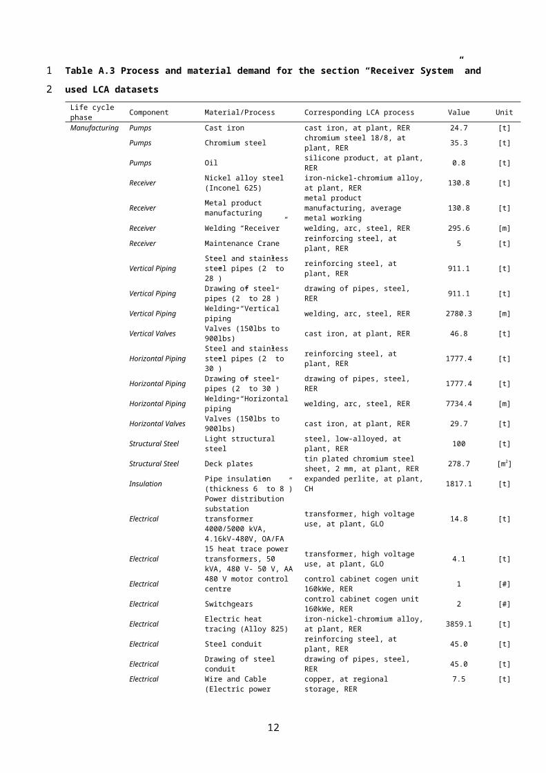
Table A.4 Process and material demand for the section “Thermal Storage System” and used LCA datasets
Life cycle phase Component Material/Process Corresponding LCA process Value Unit
Manufacturing Tanks 3 cold salt storage tanks, vertical cylindrical tank, carbon steel reinforcing steel, at plant, RER 1429 [t]
Tanks 3 hot salt storage tanks, vertical cylindrical tank, stainless steel
chromium steel 18/8, at plant, RER 1551 [t]
Molten salt Sodium nitrate (NaNO3) [t]
Molten salt Sodium carbonate (Na2CO3)
sodium carbonate from ammonium chloride production, at plant, GLO
30409 [t]
Molten salt Nitric acid (HNO3) nitric acid, 50% in H2O, at plant , RER 36143 [t]
Molten salt Potassium nitrate (KNO3)
Molten salt Potassium carbonate (K2CO3)
potassium carbonate, at plant, GLO 22221 [t]
Molten salt Nitric acid (HNO3) nitric acid, 50% in H2O, at plant , RER 20259 [t]
Molten salt Energy demand for initial melting of heat transfer fluid (salt)
diesel, burned in building machine, GLO 31.2 [TJ]
Structural Steel Light structural steel steel, low-alloyed, at plant, RER 57 [t]
Structural Steel Deck plates tin plated chromium steel sheet, 2 mm, at plant, RER 204 [m2]
Structural Steel Heavy steel (elevated platforms) reinforcing steel, at plant, RER 372 [t]Insulation Cold tank insulation (thickness 12”) Rock wool, at plant, CH 476 [t]Insulation Hot tank insulation (thickness 14”) Rock wool, at plant, CH 596 [t]
ElectricalPower distribution substation transformer 4000/5000 kVA, 4.16kV-480V, OA/FA
transformer, high voltage use, at plant, GLO 14.8 [t]
Electrical 480 V motor control center control cabinet cogen unit 160kWe, RER 1 [#]
Electrical Steel conduit reinforcing steel, at plant, RER 2.1 [t]Electrical Drawing of steel conduit drawing of pipes, steel, RER 2.1 [t]Electrical Cable trays reinforcing steel, at plant, RER 90.0 [t]
Electrical
Wire and Cable (Electric power distribution, lighting, communication, fire-smoke detectors, grounding and general wiring)
copper, at regional storage, RER 1.3 [t]
Electrical Wire drawing “Receiver” wire drawing, copper, RER 1.3 [t]Concrete work Reinforced steel “Storage” reinforcing steel, at plant, RER 54.0 [t]Concrete work Concrete “Storage” concrete, normal, at plant, CH 414.4 [m3]Concrete work Embedded metals “Storage” reinforcing steel, at plant, RER 2.6 [t]
Sitework Excavation excavation, hydraulic digger, RER 6682.0 [m3]
Sitework Backfill and compaction excavation, hydraulic digger, RER 4454.3 [m3]
Sitework Tank foundation insulation (foam glass) foam glass, at plant, RER 262.9 [t]
Sitework Refactory bricks (tank perimeter foundation)
refractory, basic, packed, at plant, DE 930.9 [t]
Sitework Sand (tank foundation) sand, at mine, CH 261.5 [t]
Painting Painting of structural steel alkyd paint, white, 60% in solvent, at plant, RER 1.6 [t]
Transport Transport services transport, freight, rail, RER 26.4 [106 tkm]
End of life Recycling steel components disposal, building, reinforcement steel, to recycling, CH 1245 [t]
Disposal steel components disposal, building, reinforcement steel, to final disposal, CH 2312 [t]
Disposal concrete components disposal, building, concrete, not reinforced, to final disposal, CH 1843 [t]
Disposal “Molten salt” disposal, inert waste, 5% water, to inert material landfill 81 [103 t]
Disposal copper components disposal, copper, 0% water, to municipal incineration, CH 1.3 [t]
Disposal glass components disposal, glass, 0% water, to inert material landfill, CH 263 [t]
Disposal mineral wool components disposal, building, mineral wool, to final disposal, CH 1072 [t]
Disposal paint disposal, paint, 0% water, to inert 1.6 [t]
12
1

material landfill, CHTransport services transport, freight, rail, RER 24.5 [106 tkm]
Steam Generation System
The two steam generators were modelled based on the heat exchanger area of the preheaters, the
superheaters, the reheaters and the evaporators. Based on the dimensions of these components the
weight of the steam generator was calculated.
The pumps in the storage system comprise hot salt pumps, spare pumps, attemperation pumps, a
startup boiler feedwater pump and two evaporation recirculation pumps. Each of the two steam
generating systems use pumps with power capacities between 200 kW and 1 MW. Inventory data for
all inputs of process pumping devices were found in the environmental product declarations (EPD) of
the pump manufacturer Sulzer (Sulzer, 2012a, 2012b, 2012c, 2012d, 2012e, 2012f, 2012g, 2012h,
2012i, 2012j, 2012k). These datasets were used to create synthetic datasets at the respective power
capacity of the pumps via parametrisation of all input flows.
The piping includes the nitrate salt pipes in the steam generation system and the recirculation water
pipes which are the inlets, outlets and connections between the superheater, the evaporator, the
reheater, the preheater and the steam drum.
Pipes are made of carbon and stainless steel at dimensions between 6” and 30”. Moreover, the
drawing of pipes was considered and the number of welds was used to calculate the total length of
welds. The valves used in the steam generation system have pressure ratings between 300 lbs and
900 lbs. In the LCA model the valves were considered based on their weight which is reported by the
valve manufacturer Powell Valves (PowellValves, 2015). For simplification it is assumed that the
main components of the valves are made of cast iron, the appropriate process was found in the
ecoinvent database.
Insulation is needed for all major piping systems and the heat exchangers. Therefor a 4” to 8” thick
isolation made of calcium silicate is used as a coating.
Electrical components of the steam generating system cover the power distribution of the pumps by
a distribution 500/600 kVA transformer, a motor control center and two switchgears. Moreover all
piping is equipped with electric heat tracing cables (Thermon, 2013). The power distribution
components were modelled based on their mass found in SWGR (2015). The material demand of the
electric infrastructure for lighting, communication, fire-smoke detectors, grounding and general wiring
is mainly made of copper cables and steel conduits.
The concrete work and the sitework include the construction of the foundations of the steam
generator, heat exchangers and the excavation and backfill works.
13
12
3
4
5
6
7
8
9
10
11
12
13
14
15
16
17
18
19
20
21
22
23
24
25
26
27
28
29
30
31
32
33

Table A.5 Process and material demand for the section “Steam Generation System” and corresponding
LCA datasets
Life cycle phase Component Material/Process Corresponding LCA process Value Unit
Manufacturing Heat exchangers2 steam generators (preheater,superheater, reheater, evaporator)
reinforcing steel, at plant, RER 535 [t]
Pumps Cast iron cast iron, at plant, RER 4.9 [t]Pumps Chromium steel chromium steel 18/8, at plant, RER 16.9 [t]Pumps Oil silicone product, at plant, RER 127 [kg]
Piping Steel and stainless steel pipes (6” to 30”) reinforcing steel, at plant, RER 73.2 [t]
Piping Drawing of steel pipes (6” to 30”) drawing of pipes, steel, RER 73.2 [t]
Piping Welding “Piping” welding, arc, steel, RER 355.6 [m]Valves Valves (300lbs to 900lbs) cast iron, at plant, RER 37.3 [t]
Insulation Pipe insulation (thickness 4” to 8”) expanded perlite, at plant, CH 123.9 [t]
ElectricalPower distribution substation transformer 500/600 kVA, 4.16kV-480V, AA/FA
transformer, high voltage use, at plant, GLO 1.2 [t]
Electrical 480 V motor control centre control cabinet cogen unit 160kWe, RER 3 [#]
Electrical Switchgears control cabinet cogen unit 160kWe, RER 2 [#]
Electrical Electric heat tracing (Alloy 825) iron-nickel-chromium alloy, at plant, RER 194.8 [t]
Electrical Steel conduit reinforcing steel, at plant, RER 5.0 [t]Electrical Drawing of steel conduit drawing of pipes, steel, RER 5.0 [t]Electrical Cable trays reinforcing steel, at plant, RER 11.1 [t]
Electrical
Wire and Cable (Electric power distribution, lighting, communication, fire-smoke detectors, grounding and general wiring)
copper, at regional storage, RER 1.8 [t]
Electrical Wire drawing “Steam Generation System” wire drawing, copper, RER 1.8 [t]
Concrete work Reinforced steel “Steam Generation System” reinforcing steel, at plant, RER 14.0 [t]
Concrete work Concrete “Steam Generation System” concrete, normal, at plant, CH 147.6 [m3]
Concrete work Embedded metals “Steam Generation System” reinforcing steel, at plant, RER 0.4 [t]
Sitework Excavation excavation, hydraulic digger, RER 73.4 [m3]Sitework Backfill excavation, hydraulic digger, RER 36.7 [m3]
Painting Painting of structural steel alkyd paint, white, 60% in solvent, at plant, RER 1.6 [t]
Transport Transport services transport, freight, rail, RER 411 [103 tkm]
Use phase Pumps Particle board particle board, cement bonded, at plant, RER 0.8 [m²]
Pumps Tap water tap water, at user, RER 190.3 [t]Pumps Oil silicone product, at plant, RER 80 [kg]Pumps Cast iron cast iron, at plant, RER 0.8 [t]
Pumps Disposal hazardous wastedisposal, hazardous waste, 25% water, to hazardous waste incineration, CH
0.6 [t]
Pumps Disposal municipal solid wastedisposal, municipal solid waste, 22.9% water, to municipal incineration, CH
1.1 [t]
Pumps Recycling disposal, building, reinforcement steel, to recycling, CH 7.0 [t]
End of life Pumps Disposal hazardous waste “Pumps”
disposal, hazardous waste, 25% water, to hazardous waste incineration, CH
80 [kg]
Pumps Recycling “Pumps” disposal, building, reinforcement steel, to recycling, CH 45.8 [t]
Recycling steel components disposal, building, reinforcement steel, to recycling, CH 320.7 [t]
Disposal steel components disposal, building, reinforcement steel, to final disposal, CH 595.6 [t]
14
12

Disposal concrete components disposal, building, concrete, not reinforced, to final disposal, CH 450.2 [t]
Disposal copper components disposal, copper, 0% water, to municipal incineration, CH 1.8 [t]
Disposal paint disposal, paint, 0% water, to inert material landfill, CH 0.6 [t]
Additional transport services disposal transport, freight, rail, RER 696 [tkm]
Electric Power Generation System
To ensure the operation of the Electric Power Generation System (EPGS) several pressurised
columns and vessels are used. These include air filters, compressed air receivers, an air dryer, a liquid
N2-storage and an open deaerating feedwater heater. Background data on the material composition and
weight of these vessels were found in the technical data sheets and the technical drawings of Aircel
(2016), Balston (2016), Express (2016) and Manchester (2016). All operational fluids of the power
block are buffered in tanks. The tank materials used are dependent on the proprieties of the fluid stored
and range from standard carbon steel and fiber glass tanks for fuels to PVC tanks to store chemicals
(e.g. chlorine or natrium carbonate).
In the water-steam cycle of the power plant heat exchangers are used as feedwater heaters,
condenser or gland steam condenser. Based on the dimensions of these components the weights of the
heat exchangers were calculated. Moreover, the component heat exchanger includes the dry cooling
towers. Basic process data on the dry cooling system was derived from Adam (2011) and up-scaled to
the exhaust steam mass flow at the condenser of the investigated solar tower configuration. It was
assumed that the material demand of the dry cooling system increases linearly with the exhaust steam
flow that has to be cooled.
Pumps supplying the feedwater, the condensate, the circulating water and the fire water were
modelled based on the LCA data given in the environmental product declarations (EPD) of the pump
manufacturer Sulzer (Sulzer, 2012a, 2012b, 2012c, 2012d, 2012e, 2012f, 2012g, 2012h, 2012i, 2012j,
2012k). The compressors used in the EPGS were modelled based on two ecoinvent datasets of
compressors. These datasets were used to create synthetic datasets at the respective power capacity of
the pumps and compressors investigated in this study via parametrisation of all input flows.
The analysis of the steam turbine and the generator set was performed by applying the material
dataset of Parthey (2010). A parametrisation to the capacity of the investigated components of this
dataset was made for all processes of the turbine and the generator. For the up-scaling of the datasets a
constant steam flow per cross-sectional area was assumed.
Pipes are made of carbon steel at dimensions between 1” and 54”. The material demand of these
different steel pipes was calculated by considering the pipe dimensions and weight factors of carbon
steel according to the formula for standardised steel pipes (Multalloy, 2015). Moreover, the drawing of
pipes was considered and the number of welds was used to calculate the total length of welds. The
material demand of the pneumatic tubing in the EPGS was calculated by assuming that all pneumatic
15
12
3
4
5
6
7
8
9
10
11
12
13
14
15
16
17
18
19
20
21
22
23
24
25
26
27
28
29
30
31
32

pipes have a diameter of 12.7 mm and a thickness of 1.5 mm (SMC, 2013). Together with the total
length of pneumatic tubes in this system and the density of polyethylene the total mass was obtained.
Structural steel is used for the supports, pipe racks, cable trays, gratings and ladders of the EPGS.
The insulation of major equipment components (e.g. feedwater pumps, feedwater heaters,
deaerator) and piping infrastructure in the EPGS is made by using calcium silicate. The thickness of
the insulation coatings varies from 4” to 6”.
A major contributor to the overall material demand can be found in the electrical engineering of the
EPGS. Especially the power distribution requires significant resources. The power distribution
comprises a main transformer and an auxiliary transformer and three load centre transformers. The
main transformer is operating at a power rating of 490/540 MVA with a primary and secondary
voltage level of 13.8 kV and 230 kV, respectively. The auxiliary transformer has a power rating of
44/50 MVA with a primary and secondary voltage level of 230 kV and 13.8 kV, respectively. Each of
the load-centre transformers is operating at a power rating of 1.0/1.12 MVA and at voltage levels of
13.8 kV and 4160 V. High voltage transformers distributing the electricity at different voltage levels in
the EPGS were modelled based on the LCA data given in the environmental product declarations
(EPD) of the transformer manufacturer ABB (ABB, 2003a, 2003b, 2003c, 2003d, 2003e, 2003f,
2003g). These datasets were used to create synthetic datasets at the respective power rating of the
transformers via parametrisation of all input flows. Additionally the bulk materials used for the
electrical engineering encompass switchgears, circuit breakers, low voltage transformers and cable and
wiring. Based on the dimensions and density of these components masses were calculated and the
corresponding LCA data was found in the ecoinvent database.
The concrete work in this section of the power plant stems from the construction of the turbine-
generator foundation, the cooling tower foundations and the fuel oil tank foundation. The sitework
includes excavation and backfill at the construction sites. LCA process data on concrete, the embedded
materials and sitework was obtained from ecoinvent database.
16
1
2
3
4
5
6
7
8
9
10
11
12
13
14
15
16
17
18
19
20
21
22
23
24
25
26

Table A.6 Process and material demand for the section “Electric Power Generation System” and
corresponding LCA datasets
17
12
Life cycle phase Component Material/Process Corresponding LCA process Value UnitManufacturing Columns and vessels Instrument air filters
Columns and vessels Casing aluminium, primary, at plant, RER 0.6 [kg]Columns and vessels Internals nylon 6, at plant, RER 0.6 [kg]Columns and vessels Compressed air receivers reinforcing steel, at plant, RER 2.4 [t]Columns and vessels Air dryer reinforcing steel, at plant, RER 0.4 [t]Columns and vessels Liquid N2-storage reinforcing steel, at plant, RER 2.8 [t]
Columns and vessels Open deaerating feedwater heater reinforcing steel, at plant, RER 14.1 [t]
Tanks Fuel oil storage glass fibre, at plant, RER 1.2 [t]Tanks Diesel generator tank reinforcing steel, at plant, RER 0.1 [t]Tanks Lubricating Oil Conditioner reinforcing steel, at plant, RER 2.2 [t]Tanks Demineralizer reinforcing steel, at plant, RER 1.9 [t]
Tanks Hyprochlorinator polyvinylchloride, bulk polymerised, at plant, RER 33.1 [kg]
Tanks Sand filtersTanks glass fibre, at plant, RER 2.9 [t]Sand sand, at mine, CH 0.8 [t]
Tanks Soda Ash Mixing polyvinylchloride, bulk polymerised, at plant, RER 17.7 [kg]
Tanks Liquid Coagulant Mixing polyvinylchloride, bulk polymerised, at plant, RER 17.7 [kg]
Tanks Chemical Feed tank chromium steel 18/8, at plant; RER 0.4 [kg]
Tanks Sodium Phosphate Dissolving Funnel chromium steel 18/8, at plant; RER 45.4 [kg]
Tanks Lime Soda Softener reinforcing steel, at plant, RER 7.1 [t]Tanks Service Water Storage glass fibre, at plant, RER 1.4 [t]Tanks Sludge Thickener reinforcing steel, at plant, RER 0.5 [t]Tanks Supernatant Storage reinforcing steel, at plant, RER 0.3 [t]Tanks Sulfuric Acid Storage reinforcing steel, at plant, RER 1.9 [t]Tanks Potable Water Storage reinforcing steel, at plant, RER 0.6 [t]Tanks Liquid Coagulant Storage reinforcing steel, at plant, RER 0.3 [t]Tanks Caustic Soda Storage reinforcing steel, at plant, RER 1.7 [t]Tanks Soda Ash Storage Bin reinforcing steel, at plant, RER 0.7 [t]Tanks Quick Lime Storage Bin reinforcing steel, at plant, RER 0.7 [t]Heat Exchangers Feed water Heaters reinforcing steel, at plant, RER 118.3 [t]Heat Exchangers Main condenser reinforcing steel, at plant, RER 241.3 [t]Heat Exchangers Gland steam condenser reinforcing steel, at plant, RER 0.1 [t]Cooling Towers Tube fins aluminium, primary, at plant, RER 1046.6 [t]
Cooling Towers
Connecting steam pipe, reinforcing steel, piping, condenser piping, condenser tank
reinforcing steel, at plant, RER
3377.8 [t]
Cooling Towers Light structural steel (scaffolding) steel, low-alloyed, at plant, RER 629.9 [t]
Cooling Towers Ventilation walls, ventilator, base plate
glass fibre reinforced plastic, polyamide, injection moulding, at plant, RER 1008.4 [t]
Cooling Towers Motors and pumps cast iron, at plant, RER 103.8 [t]Cooling Towers Zinc for galvanising zinc, primary, at regional storage, RER 2.5 [t]Cooling Towers Foundation concrete, normal, at plant, CH 35748 [m3]Cooling Towers Manufacturing of scaffolds
Section bar rolling section bar rolling, steel, RER 629.9 [t]Galvanising zinc coating, coils, RER 40.3 [m2]
Cooling Towers Manufacturing of finned tubes (tubes) drawing of pipes, steel, RER 3377.8 [t]
Cooling Towers Manufacturing of finned tubes (fins)
aluminium product manufacturing, average metal working, RER 1046.6 [t]
Pumps Cast iron cast iron, at plant, RER 23.9 [t]Pumps Chromium steel chromium steel 18/8, at plant, RER 41.6 [t]Pumps Oil silicone product, at plant, RER 0.7 [t]Pumps Low alloyed steel steel, low-alloyed, at plant, RER 14.4 [t]
CompressorsAir compressors, vacuum pumps, gland steam condenser air exhauster
Printed wiring printed wiring board, surface mount, at 2.5 [m2]
18

board plant, GLO
19

Aluminium aluminium, production mix, at plant, RER 0.9 [t]Aluminium sheet rooling sheet rolling, aluminium, RER 0.9 [t]Chromium steel sheet rolling sheet rolling, chromium steel, RER 0.9 [t]Steel sheet rolling sheet rolling, steel, RER 5.2 [t]Chromium steel chromium steel 18/8, at plant, RER 0.9 [t]Wire drawing wire drawing, copper, RER 1.1 [t]Synthetic rubber synthetic rubber, at plant, RER 57.4 [kg]Cast iron cast iron, at plant, RER 4.1 [t]Copper copper, at regional storage, RER 1.1 [t]
Polystyrene polystyrene, high impact, HIPS, at plant, RER 0.2 [t]
Injection moulding injection moulding, RER 0.2 [t]Low alloyed steel steel, low-alloyed, at plant, RER 5.2 [t]Transport freight train transport, freight, rail, RER 2613.6 [tkm]Transport lorry transport, lorry >16t, fleet average, RER 1306.8 [tkm]
Steam Turbine
Turbine Generator Package: Steam Turbine - 2 cylinder (HP and IP/LP), downward exhaust440 MWe
Reinforcing steel, reinforcing steel, at plant, RER 209.1 [t]Low alloyed steel steel, low-alloyed, at plant, RER 5.9 [t]Molybdenum molybdenum, at regional storage, RER 2.7 [t]Chromium steel chromium steel 18/8, at plant, RER 51.1 [t]Iron-nickel-chromium alloy iron-nickel-chromium alloy, at plant, RER 98.4 [t]Cast iron cast iron, at plant, RER 148.2 [t]Milling of steel components milling, steel, average, RER 49.5 [t]Milling of chromium steel components
milling, chromium steel, average, RER35.0 [t]
Milling of cast iron components milling, cast iron, average, RER 34.1 [t]
Generator Generator - 2 pole, air cooled, 490 MVA
Reinforcing steel, reinforcing steel, at plant, RER 37.5 [t]Low alloyed steel steel, low-alloyed, at plant, RER 249.4 [t]Chromium steel chromium steel 18/8, at plant, RER 0.8 [t]Iron-nickel-chromium alloy iron-nickel-chromium alloy, at plant, RER 9.4 [t]Cast iron cast iron, at plant, RER 4.4 [t]Copper copper, at regional storage, RER 47.3 [t]Ceramic tiles ceramic tiles, at regional storage, CH 0.7 [t]
Polyethylene polyethylene, HDPE, granulate, at plant, RER 5.0 [t]
Milling of steel components milling, steel, average, RER 66.0 [t]Milling of chromium steel components
milling, chromium steel, average, RER2.4 [t]
Milling of cast iron components milling, cast iron, average, RER 1.0 [t]
Cranes Turbine crane, warehouse crane reinforcing steel, at plant, RER 66 [t]
Piping Steel pipes (1” to 72”) reinforcing steel, at plant, RER 531.4 [t]Drawing of steel pipes (1” to 72”) drawing of pipes, steel, RER 531.4 [t]Welding “Vertical piping” welding, arc, steel, RER 2043.3 [m]
Pneumatic tubing polyethylene, HDPE, granulate, at plant, RER 1100.4 [kg]
Extrusion of plastic pipes extrusion, plastic pipes, RER 1100.4 [kg]
Structural Steel Supports, Pipe Racks, Cable Trays reinforcing steel, at plant, RER 290 [t]
Structural Steel Gratings and Ladders reinforcing steel, at plant, RER 26 [t]
20

Insulation Pipe and equipment insulation (thickness 6” to 8”) expanded perlite, at plant, CH 362.3 [t]
Electrical
1 x Main Transformer - 13.8 / 230 kV, 490 / 540 MVA, OA1 x Auxiliary Transformer - 230 / 13.8 kV, 44 / 50 MVA, OA3 x Load Center Transformer - 13.8 kV / 4160 V, 1.0 / 1.12 MVA, AA
Electrical steel reinforcing steel, at plant, RER 250.2 [t]Steel sheet reinforcing steel, at plant, RER 8.3 [t]Steel profile/Construction steel
reinforcing steel, at plant, RER61.2 [t]
Glass fiber glass fibre, at plant, RER 1.9 [t]Kraft paper kraft paper, unbleached, at plant, RER 1.8 [t]Copper wire copper, at regional storage, RER 54.7 [t]Wire drawing “Electric Power Generation System”
wire drawing, copper, RER
54.7 [t]Copper profile copper, at regional storage, RER 8.8 [t]
Pressspan/Wood particle board, cement bonded, at plant, RER 27.9 [m3]
Porcelain ceramic tiles, at regional storage, CH 17.5 [t]Aluminium aluminium, primary, at plant, RER 0.5 [t]
Paint alkyd paint, white, 60% in solvent, at plant, RER 2.8 [t]
Transformer oil silicone product, at plant, RER 93.2 [t]Resin polyurethane, rigid foam, at plant, RER 6 [kg]Red brass brass, at plant, CH 41 [kg]Insulation material expanded perlite, at plant, CH 7.9 [t]Heat energy heat, unspecific, in chemical plant, RER 347 [MWh]Hazardous waste “Electrical”
disposal, hazardous waste, 25% water, to hazardous waste incineration, CH 4.1 [t]
Regular waste (incl. waste water) “Electrical”
disposal, municipal solid waste, 22.9% water, to municipal incineration, CH 11083 [t]
Metalclad Switchgear - 4160 V control cabinet cogen unit 160kWe, RER 1 [#]Air Circuit Breakers - 480 V control cabinet cogen unit 160kWe, RER 1 [#]480-208/120V Dry Type Transformers
transformer, high voltage use, at plant, GLO 4.3 [t]
2 x Lighting Transformer, 30 kVA, 3 phase 480 / 277 V, Indoor
transformer, high voltage use, at plant, GLO 0.3 [t]
3 x Lighting Transformer, 30 kVA, 3 phase, 480 / 277 V, Outdoor
transformer, high voltage use, at plant, GLO 0.4 [t]
Cable trays reinforcing steel, at plant, RER 35.0 [t]Steel conduit reinforcing steel, at plant, RER 65.6 [t]Wire and Cable (Power cable, instrument and control wiring, lighting, communication, grounding and general wiring)
copper, at regional storage, RER
4.4 [t]Wire drawing “Electric Power Generation System” wire drawing, copper, RER 4.4 [t]
Concrete work Reinforced steel “turbine-generator foundation” reinforcing steel, at plant, RER 72.0 [t]Concrete “turbine-generator foundation” concrete, normal, at plant, CH 917.5 [m3]Embedded metals “turbine-generator foundation” reinforcing steel, at plant, RER 8.2 [t]Reinforced steel “Miscellaneous Footings and Foundations”
reinforcing steel, at plant, RER180 [t]
Concrete “Miscellaneous Footings and Foundations” concrete, normal, at plant, CH 2293.7 [m3]Embedded metals reinforcing steel, at plant, RER 6.8 [t]
21

“Miscellaneous Footings and Foundations”
Sitework
Excavation (Turbine generator foundation, Miscellaneous Footings and Foundations, fuel oil tank)
excavation, hydraulic digger, RER
4808 [m3]Backfill and compaction (Turbine generator foundation, Miscellaneous Footings and Foundations, fuel oil tank)
excavation, hydraulic digger, RER
1798 [m3]Transport Transport services transport, freight, rail, RER 5.0 [106 tkm]
Use phase Pumps Particle board particle board, cement bonded, at plant, RER 1754.0 [m²]
Pumps Tap water tap water, at user, RER 355.6 [t]Pumps Oil silicone product, at plant, RER 13.8 [t]Pumps Cast iron cast iron, at plant, RER 2.3 [t]
Pumps Disposal hazardous waste disposal, hazardous waste, 25% water, to hazardous waste incineration, CH 2.3 [t]
Pumps Disposal municipal solid waste
disposal, municipal solid waste, 22.9% water, to municipal incineration, CH 2.3 [t]
Pumps Recycling disposal, building, reinforcement steel, to recycling, CH 36.4 [t]
Electrical Hazardous waste “Electrical” disposal, hazardous waste, 25% water, to hazardous waste incineration, CH 5072 [t]
Electrical Regular waste (incl. waste water) “Electrical”
disposal, municipal solid waste, 22.9% water, to municipal incineration, CH 2272 [t]
End of life Cooling Tower Recycling “Cooling Tower” disposal, building, reinforcement steel, to recycling, CH 5158.1 [t]
Pumps Disposal hazardous waste “Pumps”
disposal, hazardous waste, 25% water, to hazardous waste incineration, CH 0.3 [t]
Pumps Recycling “Pumps” disposal, building, reinforcement steel, to recycling, CH 59.3 [t]
Compressors Disposal rubber “Compressors”
disposal, rubber, unspecified, 0% water, to municipal incineration, CH 57.4 [kg]
Compressors Disposal polystyrene “Compressors”
disposal, polystyrene, 0.2% water, to municipal incineration, CH 149.5 [kg]
Electrical Hazardous waste “Electrical” disposal, hazardous waste, 25% water, to hazardous waste incineration, CH 5072 [t]
Electrical Regular waste (incl. waste water) “Electrical”
disposal, municipal solid waste, 22.9% water, to municipal incineration, CH 2272 [t]
Disposal paint disposal, paint, 0% water, to inert material landfill, CH 2.8 [t]
Recycling steel components disposal, building, reinforcement steel, to recycling, CH 1067.5 [t]
Disposal steel components disposal, building, reinforcement steel, to final disposal, CH 1982.5 [t]
Disposal concrete components
disposal, building, concrete, not reinforced, to final disposal, CH 11372 [t]
Disposal copper components disposal, copper, 0% water, to municipal incineration, CH 61.6 [t]
Disposal glass disposal, glass, 0% water, to inert material landfill, CH 7.4 [t]
Disposal aluminium disposal, aluminium, 0% water, to municipal incineration, CH 1048 [t]
Disposal plasticsdisposal, building, polyethylene/polypropylene products, to final disposal, CH 1014.8 [t]
Transport services transport, freight, rail, RER 336 [103 tkm]
Fossil Co-firing during power plant operation
Significant demands during the use phase of a CSP plant stem from the co-firing depicted in Error:
Reference source not found. To prevent the molten salt heat transfer fluid from freezing and to avoid
part-load behaviour in the thermal process, a fossil-co-firing unit is added to the system. Today CSP
plants are using fired heaters with waste heat recovery system as reported in Hunold (2012). The
amount of co-firing used in CSP plants is dependent on the CSP configuration type, the costs and
22
12
3
4
5
6
7

availability of fossil fuels at the power plant site and existing renewable energy policies. For the co-
firing rate we assume as an upper boundary 12% of the yearly electricity production similar to the
renewable energy regulations regarding CSP plants in the Spanish energy system, where most of the
current CSP capacity is installed (RoyalDecree, 2004). The minimum co-firing rate assumed in this
study is determined at 2%, reported as co-firing amount necessary to allow CSP plant operation at
distant CSP plant locations in Southern Africa (Geyer, 2014). To include these co-firing shares into
the existing power plant concept, the electricity generation given in Error: Reference source not found is
increased based on the additional electricity generation from fossil fuels. The resulting net electricity
yields of the solar power plant including the minimum and maximum co-firing shares account for
1600 GWhel/a and 1780 GWhel/a, respectively. In both cases it is assumed that diesel is used for co-
firing and that the diesel transport is achieved by freight train. No information was found on the
construction materials necessary to build the fired heaters.
Based on these assumptions the minimum and maximum co-firing amounts were calculated and the
corresponding LCA data was found in the ecoinvent database.
Table A.7 Minimum and maximum process and material demands for the section “Fossil co-firing” and
used LCA datasets
Life cycle phase Component Material/Process Corresponding LCA process Value Unit
Use phase Co-Firing (max) Co-firing diesel burneddiesel, burned in diesel-electric generating set, GLO 1875 [TJ/a]
Co-Firing (max) Transport diesel transport, freight, rail, RER 13.0 [106 tkm]
Use phase Co-Firing (min) Co-firing diesel burneddiesel, burned in diesel-electric generating set, GLO 313 [TJ]
Co-Firing (min) Transport diesel transport, freight, rail, RER 2.2 [106 tkm]
23
1
2
3
4
5
6
7
8
9
10
11
12
13
14
1516
17
18192021