Embed Size (px)
Citation preview
Design of a FOD Inspection System for the Aircraft Production Process
Justin Amoyal, Roman Garber, Marwan Karama, Meba Kassahun, Anoosha Koohi
Abstract— Fighter jets provide the super powers of this day and age with unmatched military capabilities in the skies over the battlefield. The continuously growing capabilities of these aircrafts are constantly driving the demand. Yet as time advances the fighter jet production industry has experienced exceedingly high price rises. This creates a matched and constantly growing demand for ways to improve the production process of these fighter jets to ultimately reduce costs, and increase safety.
Foreign Object Debris (FOD) can simply be defined as objects left behind or overlooked during production that are not supposed to be there. Examples of FOD include items such as nuts, bolts, screws and even trash left behind by mechanics working on the production line. The further these items are contained in aircraft sub-assembly components through the production process the more detrimental they are to the aircraft production corporation. The current inspection is manual, and provides a large potential for human error.
An enhanced FOD inspection system has been proposed that will combine X-ray imaging technology and differential imaging software. The X-ray imaging software will provide a multi-layer view while the differential imaging software will assist the system operator in decision making. A simulation has been developed that will assist Aircraft Production Corporations in selecting the best X-ray alternative for the inspection stations within their specific production process. This simulation will be capable of adapting to any aircraft production process and will accept inputs to match the production statistics; providing a means of comparison for analysis with the proposed system.
I. CONTEXT
This Fighter and Attack aircraft are the most exciting machines in the sphere of military power because of their design, speed, and weaponry. Designed with the overall battle space in mind, the F-35 Lightning II is the most technologically sophisticated multirole fighter built in history. The advanced capabilities that the F-35 is equipped with will enable its pilots to be six to eight times more effective in air-to-air missions, air-to-ground missions and surveillance missions. These and other similar properties makes it to be the dominant aircraft for the next 50 years and our project mainly focuses on its production.
Due to the complexity involved in creating the most advanced fighter jet in history, the F-35 production process utilizes the resources of 1400 suppliers nation-wide [14]. A method called the Fighter Production Process (FPP) was established to separate the production process into two teams – The Factory Flow Team and the Supplier Collaboration and
Development Team. The Factory Flow Team is responsible for preparing and enabling the production line to deliver F35 exact manufacturing standards and predictable tact or cadence time. 5000 kits containing 25000 parts are delivered to the F35 flow center where they are put through a robust provisioning process established to ensure regulated flow. The Supplier Collaboration and Development Team has three main objectives; meeting throughput demands, affordability targets, and reducing supply chain risks.
The production process of this unique and advanced fighter jet kicks off with four stages that occur simultaneously. As the fighter jet advances throughout production other stages are met simultaneously prior to the system reaching the Electronic Mate and Alignment System. (EMAS) These stages mark the initial assembly of the multiple fuselages (Aft, Center, Forward), inner wing module, right and left wings, and nose of the F35. Post-EMAS the aircraft will reach Final Assembly where the engine will be inputted into the fighter jet. Lastly, the aircraft will go to Final Finishes and complete its final tests prior to delivery.
We have displayed a flow diagram of the key production stages of the F-35.
Throughout each of these stages of production there are many complicated procedures that take place, which inherently present an opportunity for foreign object debris (FOD). Foreign object debris refers to any object that is not supposed to be there and that can cause damage to it. FOD damage is
estimated to cost the aerospace industry $4 billion a year. It can be anything from screws, bolts, tools that are used to build the aircraft to trash. FOD can be placed in the aircraft pre-production, during production and post-production. For this project, post production FOD’s which includes runway debris and birds are out scope. This project focuses FOD generated during the production of the F-35 in Fort Worth, Texas.
0
1
2
3
4
5
0.1 0.2 0.3 0.4 0.5 0.6 0.7 0.8 0.9 1
p(Search Sucess)
Num
ber o
f Ins
pect
ors
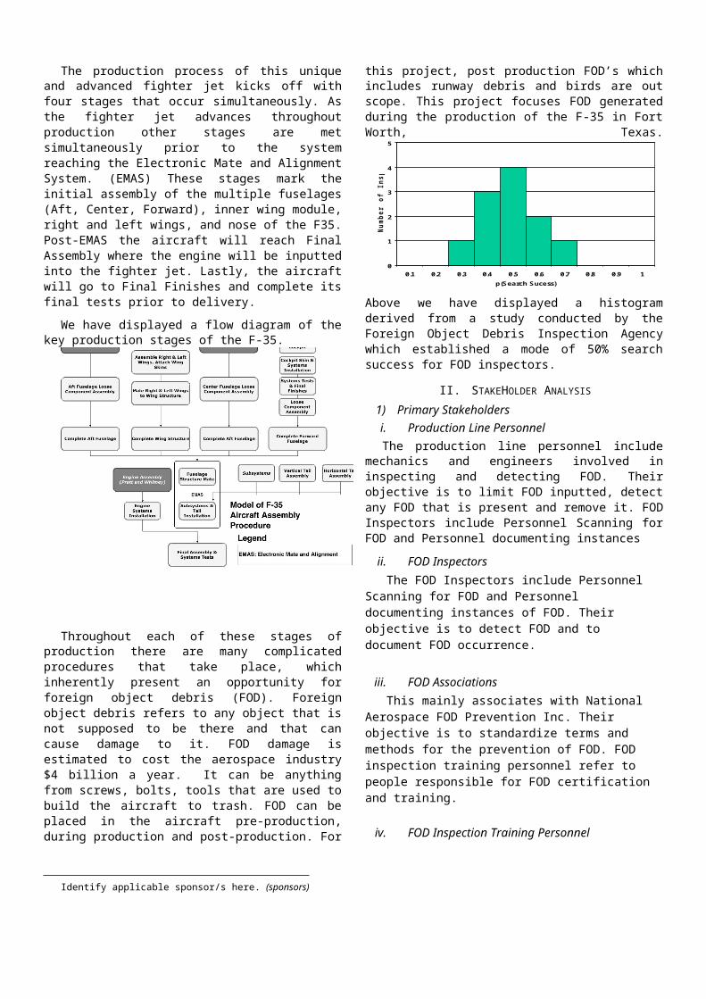
Above we have displayed a histogram derived from a study conducted by the Foreign Object Debris Inspection Agency which established a mode of 50% search success for FOD inspectors.
II. STAKEHOLDER ANALYSIS 1) Primary Stakeholdersi. Production Line PersonnelThe production line personnel include mechanics and
engineers involved in inspecting and detecting FOD. Their objective is to limit FOD inputted, detect any FOD that is present and remove it. FOD Inspectors include Personnel Scanning for FOD and Personnel documenting instances
ii. FOD Inspectors The FOD Inspectors include Personnel Scanning for FOD
and Personnel documenting instances of FOD. Their objective is to detect FOD and to document FOD occurrence.
iii. FOD AssociationsThis mainly associates with National Aerospace FOD
Prevention Inc. Their objective is to standardize terms and methods for the prevention of FOD. FOD inspection training personnel refer to people responsible for FOD certification and training.
iv. FOD Inspection Training PersonnelFOD inspection training personnel refer to people
responsible for FOD certification and training. Their objective is to teach FOD prevention to employees.
2) Secondary StakeholdersAircraft Production Coroporation
Lockheed Martin as a corporation will go under this category. As a company its objective is to Eliminate FOD during customer delivery. This has to be done in efficient and quick manner such as limiting rework and repair time.
Aircraft Customers Aircraft customers include three US Government Branches
and international F-35 Customers. Their objective is safety, advanced aircraft capabilities and to get delivery in timely manner.
Aircraft PilotsAircraft pilots refers to test pilots and pilots after testing.
Their objective is to test aircraft and complete mission safely.
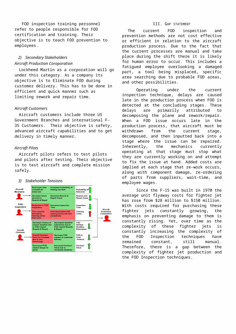
3) Stakeholder Tensions
III. GAP STATEMENT The current FOD inspection and prevention methods are
not cost effective or efficient in relation to the aircraft production process. Due to the fact that the current processes are manual and take place during the shift there it is likely for human error to occur. This includes a fatigued employee overlooking a damaged part, a tool being misplaced, specific area searching due to probable FOD areas, and other possibilities.
Operating under the current inspection technique, delays are caused late in the production process when FOD is detected at the concluding stages. These delays are primarily attributed to decomposing the plane and rework/repair. When a FOD issue occurs late in the production process, that aircraft must be withdrawn from the current stage, decomposed, and then inputted back into a stage where the issue can be repaired. Inherently, the mechanics currently operating at that stage must stop what they are currently working on and attempt to fix the issue at hand. Added costs are implied at each stage that re-work occurs, along with component damage, re-ordering of parts from suppliers, wait-time, and employee wages.
Since the F-15 was built in 1970 the average unit flyaway costs for fighter jet has rose from $28 million to $150 million. With costs required for purchasing these fighter jets constantly growing, the emphasis on preventing damage to them is constantly rising. Yet, over time as the complexity of these fighter jets is constantly increasing the complexity of the
Identify applicable sponsor/s here. (sponsors)
FOD Inspection techniques have remained constant, still manual. Therefore, there is a gap between the complexity of fighter jet production and the FOD Inspection techniques.
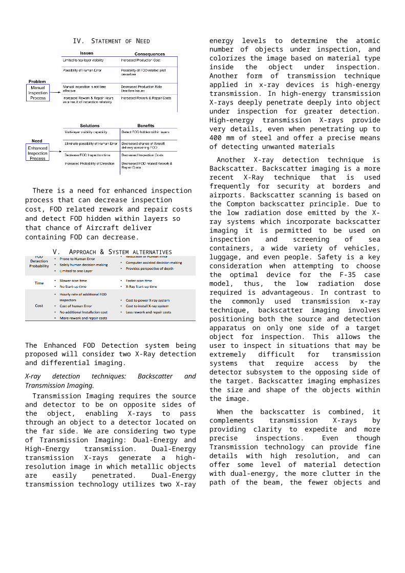
IV. STATEMENT OF NEED
There is a need for enhanced inspection process that can decrease inspection cost, FOD related rework and repair costs and detect FOD hidden within layers so that chance of Aircraft deliver containing FOD can decrease.
V. APPROACH & SYSTEM ALTERNATIVES
The Enhanced FOD Detection system being proposed will consider two X-Ray detection and differential imaging.
X-ray detection techniques: Backscatter and Transmission Imaging.
Transmission Imaging requires the source and detector to be on opposite sides of the object, enabling X-rays to pass through an object to a detector located on the far side. We are considering two type of Transmission Imaging: Dual-Energy and High-Energy transmission. Dual-Energy transmission X-rays generate a high-resolution image in which metallic objects are easily penetrated. Dual-Energy transmission technology utilizes two X-ray energy levels to determine the atomic number of objects under inspection, and colorizes the image based on material type inside the object under inspection. Another form of transmission technique applied in x-ray devices is high-energy transmission. In high-energy transmission X-rays deeply penetrate deeply into object under inspection for greater detection. High-energy transmission X-rays provide very details, even when penetrating up to 400 mm
of steel and offer a precise means of detecting unwanted materials
Another X-ray detection technique is Backscatter. Backscatter imaging is a more recent X-Ray technique that is used frequently for security at borders and airports. Backscatter scanning is based on the Compton backscatter principle. Due to the low radiation dose emitted by the X-ray systems which incorporate backscatter imaging it is permitted to be used on inspection and screening of sea containers, a wide variety of vehicles, luggage, and even people. Safety is a key consideration when attempting to choose the optimal device for the F-35 case model, thus, the low radiation dose required is advantageous. In contrast to the commonly used transmission x-ray technique, backscatter imaging involves positioning both the source and detection apparatus on only one side of a target object for inspection. This allows the user to inspect in situations that may be extremely difficult for transmission systems that require access by the detector subsystem to the opposing side of the target. Backscatter imaging emphasizes the size and shape of the objects within the image.
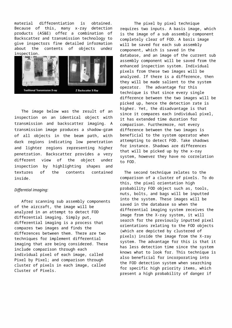
When the backscatter is combined, it complements transmission X-rays by providing clarity to expedite and more precise inspections. Even though Transmission technology can provide fine details with high resolution, and can offer some level of material detection with dual-energy, the more clutter in the path of the beam, the fewer objects and material differentiation is obtained. Because of this, many x-ray detection products (AS&E) offer a combination of Backscatter and transmission technology to give inspectors fine detailed information about the contents of objects under inspection.
The image below was the result of an inspection on an identical object with transmission and backscatter imaging. A transmission image produces a shadow-gram of all objects in the beam path, with dark regions indicating low penetration and lighter regions representing higher penetration. Backscatter provides a very different view of the object under inspection by highlighting shapes and textures of the contents contained inside.
Differntial imaging:
After scanning sub assembly components of the aircraft, the image will be analyzed in an attempt to detect FOD
differential imaging. Simply put, differential imaging is a process that compares two images and finds the differences between them. There are two techniques for implement differential imaging that are being considered. These include comparison through each individual pixel of each image, called Pixel by Pixel; and comparison through cluster of pixels in each image, called Cluster of Pixels.
The pixel by pixel technique requires two inputs. A basis image, which is the image of a sub assembly component completely clear of FOD. A basis image will be saved for each sub assembly component, which is saved in the database, and an image of the current sub assembly component will be saved from the enhanced inspection system. Individual pixels from these two images will be analyzed. If there is a difference, then they will be made salient to the system operator. The advantage for this technique is that since every single difference between the two images will be picked up, hence the detection rate is higher. Yet, the disadvantage is that since it compares each individual pixel, it has extended time duration for comparison. Furthermore, not every difference between the two images is beneficial to the system operator when attempting to detect FOD. Take shadows for instance. Shadows are differences that will be picked up by the x-ray system, however they have no correlation to FOD.
The second technique relates to the comparison of a cluster of pixels. To do this, the pixel orientation high probability FOD object such as, tools, nuts, bolts, and bags will be inputted into the system. These images will be saved in the database so when the differential imaging system receives the image from the X-ray system, it will search for the previously inputted pixel orientations relating to the FOD objects (which are depicted by clustered of pixels) inside the image from the X-ray system. The advantage for this is that it has less detection time since the system knows what to look for. This technique is also beneficial for incorporating into the FOD detection system when searching for specific high priority items, which present a high probability of danger if over looked in the production process. However, the disadvantage to this technique is that it is not possible to detect any difference if they are not previously inputted into the system.
The proposed solution of use concerning these methods is to evaluate the need and probability of each station where differential imaging could be used. The aircraft sub assembly components which have a high rate of FOD and probability of FOD detection have to be identified. Then a combination of multiple techniques in high probability areas where FOD is detected could be implemented. In the case of an area of high probability of FOD detection, pixel by pixel could produce a high reliability rate in detecting FOD. For areas where FOD is not highly probable to be detected, comparing clustered of pixels technique could be implemented due to its rapid comparison time. Also, differential imaging is a tool for the employees to analyze the image from the X-ray system not a decision making tool by itself.
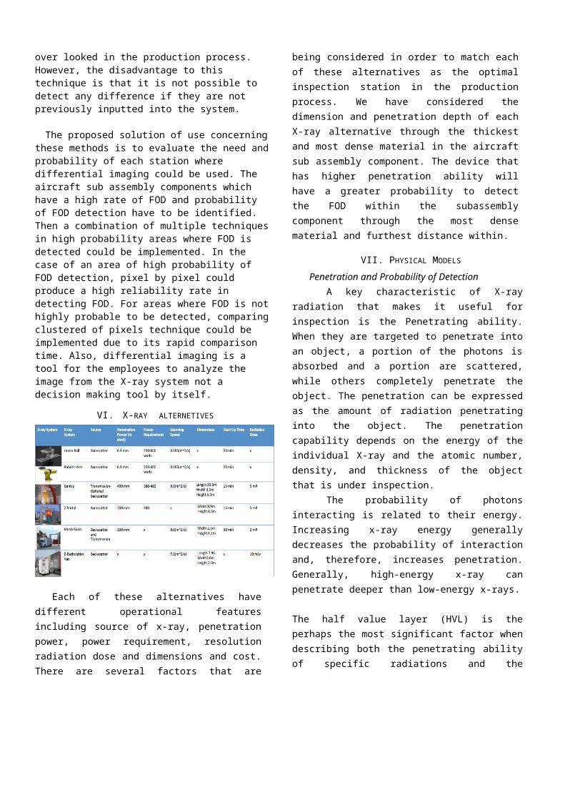
VI. X-RAY ALTERNETIVES
Each of these alternatives have different operational features including source of x-ray, penetration power, power requirement, resolution radiation dose and dimensions and cost. There are several factors that are being considered in order to match each of these alternatives as the optimal inspection station in the production process. We have considered the dimension and penetration depth of each X-ray alternative through the thickest and most dense material in the aircraft sub assembly component. The device that has higher penetration ability will have a greater probability to detect the FOD within the subassembly component through the most dense material and furthest distance within.
VII. PHYSICAL MODELS
Penetration and Probability of Detection A key characteristic of X-ray radiation that makes
it useful for inspection is the Penetrating ability. When they are targeted to penetrate into an object, a portion of the photons is absorbed and a portion are scattered, while others completely penetrate the object. The penetration can be expressed as the amount of radiation penetrating into the object. The penetration capability depends on the energy of the individual X-ray and the atomic number, density, and thickness of the object that is under inspection.
The probability of photons interacting is related to their energy. Increasing x-ray energy generally decreases the probability of interaction and, therefore, increases penetration. Generally, high-energy x-ray can penetrate deeper than low-energy x-rays.
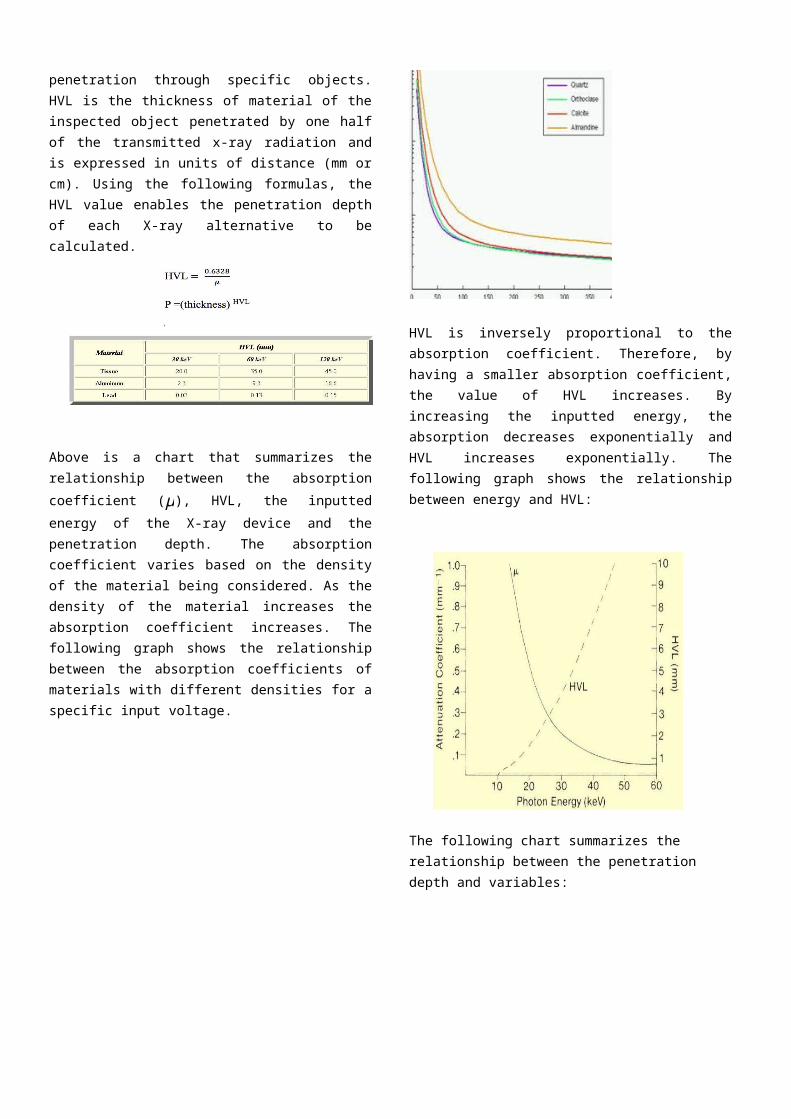
The half value layer (HVL) is the perhaps the most significant factor when describing both the penetrating ability of specific radiations and the penetration through specific objects. HVL is the thickness of material of the inspected object penetrated by one half of the transmitted x-
ray radiation and is expressed in units of distance (mm or cm). Using the following formulas, the HVL value enables the penetration depth of each X-ray alternative to be calculated.
Above is a chart that summarizes the relationship between the absorption coefficient (μ), HVL, the inputted energy of the X-ray device and the penetration depth. The absorption coefficient varies based on the density of the material being considered. As the density of the material increases the absorption coefficient increases. The following graph shows the relationship between the absorption coefficients of materials with different densities for a specific input voltage.
HVL is inversely proportional to the absorption coefficient. Therefore, by having a smaller absorption coefficient, the value of HVL increases. By increasing the inputted energy, the absorption decreases exponentially and HVL increases exponentially. The following graph shows the relationship between energy and HVL:
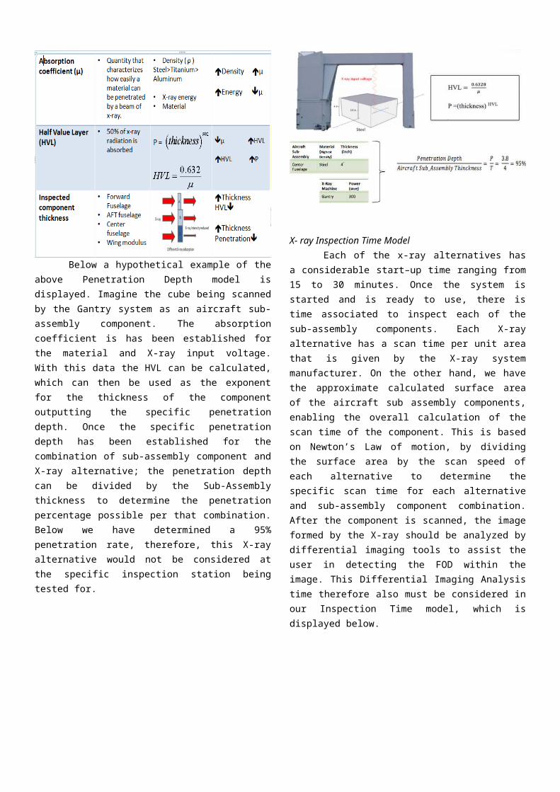
The following chart summarizes the relationship between the penetration depth and variables:
Below a hypothetical example of the above Penetration Depth model is displayed. Imagine the cube being scanned by the Gantry system as an aircraft sub-assembly component. The absorption coefficient is has been established for the material and X-ray input voltage. With this data the HVL can be calculated, which can then be used as the exponent for the thickness of the component outputting the specific penetration depth. Once the specific penetration depth has been established for the combination of sub-assembly component and X-ray alternative; the penetration depth can be divided by the Sub-Assembly thickness to determine the penetration percentage possible per that combination. Below we have determined a 95% penetration rate, therefore, this X-
ray alternative would not be considered at the specific inspection station being tested for.
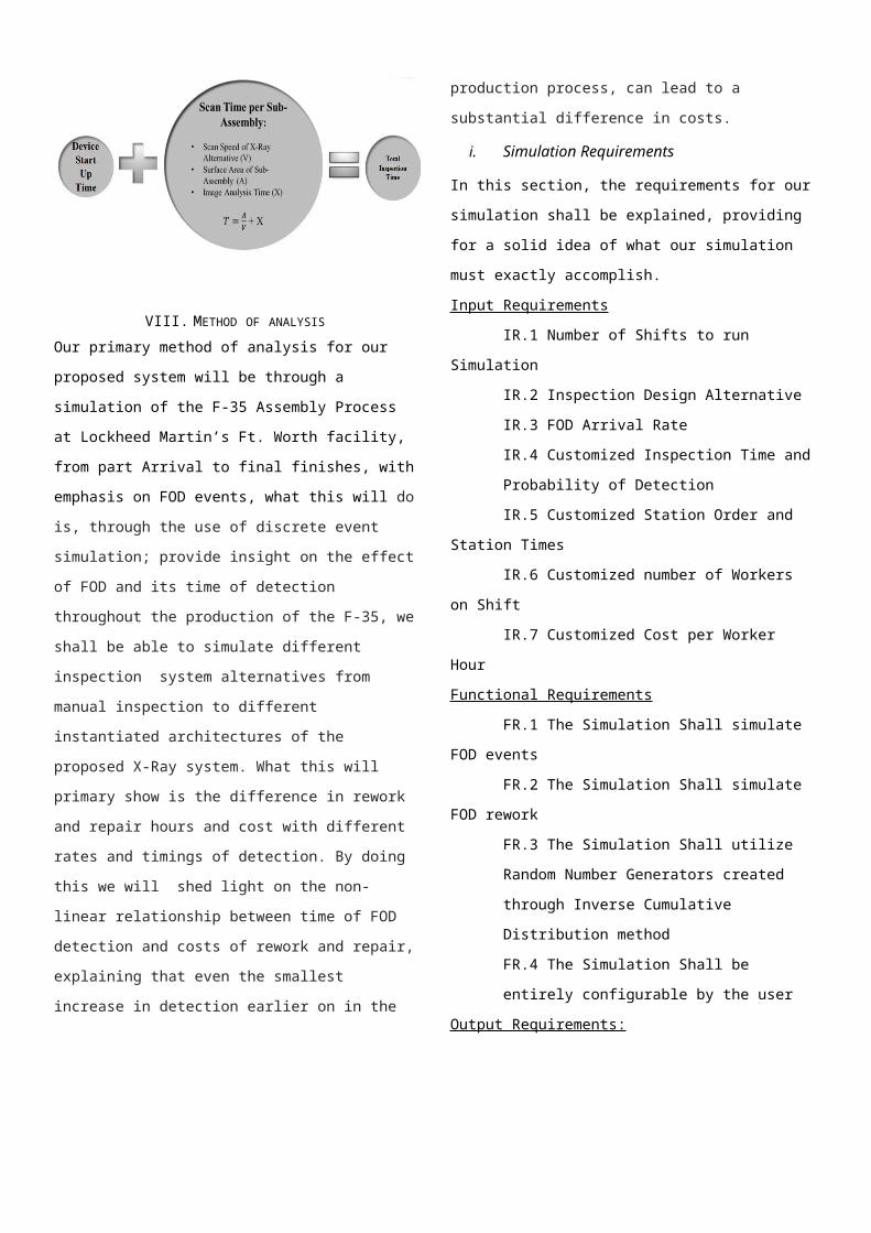
X- ray Inspection Time ModelEach of the x-ray alternatives has a considerable
start–up time ranging from 15 to 30 minutes. Once the system is started and is ready to use, there is time associated to inspect each of the sub-assembly components. Each X-ray alternative has a scan time per unit area that is given by the X-ray system manufacturer. On the other hand, we have the approximate calculated surface area of the aircraft sub assembly components, enabling the overall calculation of the scan time of the component. This is based on Newton’s Law of motion, by dividing the surface area by the scan speed of each alternative to determine the specific scan time for each alternative and sub-assembly component combination. After the component is scanned, the image formed by the X-ray should be analyzed by differential imaging tools to assist the user in detecting the FOD within the image. This Differential Imaging Analysis time therefore also must be considered in our Inspection Time model, which is displayed below.
VIII. METHOD OF ANALYSIS
Our primary method of analysis for our proposed system will
be through a simulation of the F-35 Assembly Process at
Lockheed Martin’s Ft. Worth facility, from part Arrival to
final finishes, with emphasis on FOD events, what this will do
is, through the use of discrete event simulation; provide
insight on the effect of FOD and its time of detection
throughout the production of the F-35, we shall be able to
simulate different inspection system alternatives from manual
inspection to different instantiated architectures of the
proposed X-Ray system. What this will primary show is the
difference in rework and repair hours and cost with different
rates and timings of detection. By doing this we will shed
light on the non-linear relationship between time of FOD
detection and costs of rework and repair, explaining that even
the smallest increase in detection earlier on in the production
process, can lead to a substantial difference in costs.
i. Simulation Requirements
In this section, the requirements for our simulation shall be
explained, providing for a solid idea of what our simulation
must exactly accomplish.
Input Requirements
IR.1 Number of Shifts to run Simulation
IR.2 Inspection Design Alternative
IR.3 FOD Arrival Rate
IR.4 Customized Inspection Time and Probability of
Detection
IR.5 Customized Station Order and Station Times
IR.6 Customized number of Workers on Shift
IR.7 Customized Cost per Worker Hour
Functional Requirements
FR.1 The Simulation Shall simulate FOD events
FR.2 The Simulation Shall simulate FOD rework
FR.3 The Simulation Shall utilize Random Number
Generators created through Inverse Cumulative
Distribution method
FR.4 The Simulation Shall be entirely configurable
by the user
Output Requirements:
OR.1 Total production time per Aircraft
OR.2 Total Labor hours & cost per Aircraft
OR.3 Total Rework & Repair hours per Aircraft
OR.4 Station Utilizations
OR.5 Queue Statistics for each part (Insight on Wait
Time)
ii. Simulation Variables
For our simulation, the variables and parameters shall be
derived in two ways, the first way being through random
number generation, and the second way being mathematical
and physical derivation using the methods from our Inspection
Time and Probability of Detection model and then generating
those variables by choosing an appropriate random number
generator.
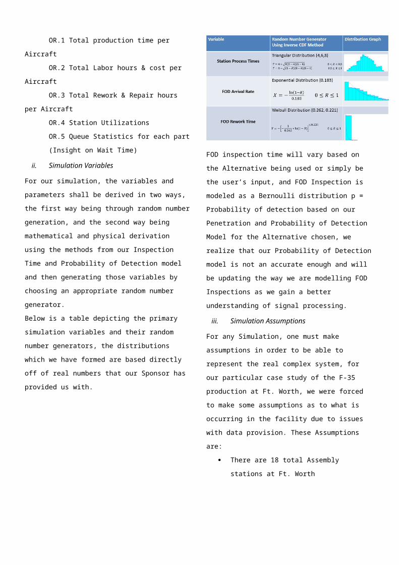
Below is a table depicting the primary simulation variables
and their random number generators, the distributions which
we have formed are based directly off of real numbers that our
Sponsor has provided us with.
FOD inspection time will vary based on the Alternative being
used or simply be the user’s input, and FOD Inspection is
modeled as a Bernoulli distribution p = Probability of
detection based on our Penetration and Probability of
Detection Model for the Alternative chosen, we realize that
our Probability of Detection model is not an accurate enough
and will be updating the way we are modelling FOD
Inspections as we gain a better understanding of signal
processing.
iii. Simulation Assumptions
For any Simulation, one must make assumptions in order to be
able to represent the real complex system, for our particular
case study of the F-35 production at Ft. Worth, we were
forced to make some assumptions as to what is occurring in
the facility due to issues with data provision. These
Assumptions are:
There are 18 total Assembly stations at Ft. Worth
There is always enough parts, essentially an
unlimited stack of beginning parts, meaning that
there are no varying arrival time at the beginning of
any Subassembly chain
Each Station has a FOD Arrival rate
Each Station has a chance to detect FOD (By Eye)
If FOD is detected rework is performed at the Station
that created the FOD
Inspection Stations do not produce FOD
iv. Simulation Flow
This diagram above depicts the flow of our simulation,
logically showing how the subassembly objects will run
through each station where they are worked on for a duration
determined by the Triangular distribution random number
generator, with a chance to create and detect FOD on sight,
modelled by exponential distribution and Bernoulli
distributions respectively. If FOD is missed, the subassembly
will continue forward to the next station, until it reaches an X-
Ray inspection station will have a significantly higher
probability of detection than the standard assembly stations. If
FOD is detected, it will be sent to have the rework and repair
necessary for it to be completed, which is modelled by the
Weibull distribution random number generator described
earlier.
v. Simulation Validation
The best way to validate our simulation would be to
allow the user to input their own station process times, FOD
arrival rate and rework time and running the simulation for a
controlled period that had already passed, and then comparing
the simulation output to their costs, if our simulation is
working correctly and the user had inputted accurate data,
then there will be correlation between the simulation output
and the actual costs that the company had expended.
IX. BUSINESS MODEL & THE RESULTS
Weighing the ResultsUsing the swing weights method, a weight will be
established for the various objectives attempting to be met through the implementation of this enhanced FOD inspection system. Aside from a weight, a preference (higher the better or lower the better) and a distribution will be associated with each of these objectives. Using research, a physical model, and simulation output a score will be established for each of the X-ray alternatives. Due to the fact that the needs and preferences per inspection station vary a different score will be calculated per inspection station on the viable X-ray alternatives at each location. Below we have displayed three score tables varied by results from research, physical model, and simulation output.
Return on Investment (ROI):
It is important to emphasize once again that a key feature of the simulation is the customizable capability, which enables it to adapt to any aircraft production corporation. Due to issues with proprietary data it is very difficult to attain realistic data points from our sponsor Lockheed Martin, yet once the simulation is completed, it can be provided as a tool for Lockheed Martin. This will enable them to evaluate whether or not the investment in the enhanced FOD inspection system is worth it.
Initially, Lockheed Martin will input their current production statistics into the simulation, which will output the data points to later be compared. This time when the simulation runs, all of the manual inspection stations will be operational. After receiving the output, the simulation will be run again yet this time with the implementation of the enhanced FOD inspection system. Using both outputs ROI analysis can be performed. By compiling total production costs from each simulation output with and without the enhanced FOD inspection system cost evaluation will be made possible. Several years of FOD related data per aircraft Production Corporation will be beneficial to the ROI analysis. By running the simulation for each year we can show the expectedly high amount of hours and costs that could have been saved by previously implementing the proposed system.
X. ACKNOWLEDGMENTS
XI. REFERENCES
[1] CombatAirCraft "Fighter/Attack Aircraft." Combataircraft.com. N.p., n.d. Web. 07 Nov. 2014.
[2] Lockheed Martin("About: F-35 Fast Facts | F-35 Lightning II." F-35 Lightning II. Lockheed Martin, n.d. Web. 28 Sept. 2014.)
[3] MiGFlug "MiGFlug.com Blog." MiGFlugcom Blog. MIGFLUG, 4 June 2014. Web. 27 Sept. 2014.)
[4] Aviation Weekly (See, inter alia, Bill Sweetman, “Denmark bails from JSF,” Aviation Week/Ares blog, March 15, 2010.)
[5] Congressional Budget Office"Congressional Budget Office." Replace the Joint Strike Fighter Program With F-16s and F/A-18s. Congressional Budget Office, 13 Nov. 2013. Web. 28 Sept. 2014.)
[6] American Science and Technology, “Z BACKSCATTER VAN,” AS&E, Massachusetts, USA, Tech. Report. ZBVDATA_080307, 2007.
[7] American Science and Technology, “MOBILESEARCH HE,” AS&E, Massachusetts, USA, Tech. Report. MSHEDATA_012711, 2011.
[8] American Science and Technology, “Omniview Gantry High-Performance Inspection System,” AS&E, Massachusetts, USA, Tech. Report. OVDATA_101711, 2011.
[9] American Science and Technology, “Z PORTAL,” AS&E, Massachusetts, USA, Tech. Report. ZPORTALDATA_052510, 2010.
[10] Aronstein and Piccirillo 1997, p. 267. Pae, Peter. "Stealth fighters fly off the radar". Los Angeles Times, 23 April 2008. Retrieved 27 April 2008.
[11] Batchel, B. 2014. “Foreign Object Debris and Damage Prevention” [Online] Available: http://www.boeing.com/commercial/aeromagazine/aero_01/textonly/s01txt.html
[12] Butler, Amy. "Last Raptor Rolls Off Lockheed Martin Line."Aviation Week, 27 December 2011. Retrieved: 10 April 2014.
[13] Parsons, Gary. "Final F-22 Delivered" Combat Aircraft Monthly, 3 May 2012. Retrieved: 10 April 2014. "FY 2011 Budget Estimates" (PDF). US: Air Force. February 2010. pp. 1–15..
[14] Callerame, , "X-Ray Back scatter Imaging: Photography Through Barriers". Retrieved September, 2014 Available: http://www.icdd.com
[15] CTOL SWBS Manufacturing Sequence Flow” 2011. [Online] Available: http://information2share.wordpress.com/2011/05/25/ctol-swbs-manufacturing-sequence-flow/
[16] Davies and Dildy 2007, p. 249. "McDonnell Douglas F-15 Streak Eagle fact sheet".National Museum of the United States Air Force. Retrieved24 September 2010.
[17] Garber, M , Diagnostic imaging and differential diagnosis in 2 case reports , J Orthop Sports
[18] Phys Ther. , vol 35 , no , p.745 – 754[19] Gemini® 7555". Retrieved September , 2014 Available: http://as-
e.com/products-solutions/parcel-inspection/gemini-6040[20] Fessle, C J, , "Physics of Projection Radiography ". RetrievedSeptember
, 2014 Available: http://web.eecs.umich.edu."Backscatter Radiography". RetrievedSeptember , 2014 Available: http://www.nucsafe.com
[21] FOREIGN OBJECT DAMAGE PREVENTION. [Online]. Available: http://
[22] www.lockheedmartin.com/content/dam/lockheed/data/aero/documents/scm/terms/fod/fod.pdf
[23][24] FOD PREVENTION GUIDELINE [Online]. Available:
http://www.nafpi.com/nafpiguideline.pdf
[25] Foreign Object Debris/Foreign Object Damage (FOD) Prevention Training
Program[Online].Available:http://www.ittaerospace.com/download/pdf/aerospace/fod_prevention_training_program.pdf
[26] F35.com "Iraq Accepts First Lockheed Martin F-16 Aircraft • Lockheed Martin". Retrieved 13 September 2014."F-16 Fact Sheet.". Retrieved 13 September 2014 Lockheed Martin. 2014. “Combining Teamwork and Technology” [Online] Available: https://www.f35.com/about/life-cycle/production
[27] Lieberman, J. 2012. “Reduction of rework at a large aerospace manufacturer” Available:http://hdl.handle.net/1721.1/73417
[28] Jean, G. 2008. “F-35 factory: One aircraft per day by 2016” [Online] Available: http://
[29] www.nationaldefensemagazine.org/archive/2008/July/Pages/F-35fact2282.aspx
[30] King, Samuel Jr. "First F-35 arrives at Eglin." U.S. Air Force, 15 July 2011. Retrieved: 20 July 2011. "BAE Systems completes 150th aircraft for F35 fighter programme".Butler, Amy. "F-35 Deal Targets Unit Cost Below $100 Million." Aviation Week. N.p., n.d. Web. 10 Nov. 2014.
[31] Procedure for the Control and Prevention of Foreign Object Debris [Online]. Available:
[32] http://theatlasgroup.biz/wp-content/uploads/2013/05/MF7P210-NC.pdf[33][34][35] Yang, H , "'jstack' - Stack Tracer of JVM Threads ".
RetrievedSeptember , 2014 Available: http://www.herongyang.com/Java-Tools/jstack-JVM-Thread-Dump-Stack-Strace.html


![A Comparison of Two Takeoff and Climb Out Flap Retraction ...catsr.ite.gmu.edu/pubs/ICNS_2016_CompareFlapRetract_12292015[1].pdf · Procedure Flap retraction is part of the takeoff](https://img.pdfslide.us/doc/110x75/5b3c16137f8b9a986e8cc9c4/a-comparison-of-two-takeoff-and-climb-out-flap-retraction-catsritegmuedupubsicns2016compareflapretract122920151pdf.jpg)