Embed Size (px)
Citation preview
International Journal of Enhanced Research Publications, ISSN: XXXX-XXXXVol. 2 Issue 4, April-2013, pp: (1-4), Available online at: www.erpublications.com
Smart Tracker Dual axes solar tracking using LDRs and Timer
Divya mereddy, Vijay Rama Raju .V, Tarun Sadula Electrical and Electronics Engineering
GRIET, Hyderbad [email protected]
Abstract: Photo voltaic cell (PV cells) is one of the methods of converting solar power to electric power. It consists of semi conductors which exhibit the photovoltaic effect and converts the solar energy to direct current. The output power of the PV cells depends on the angle of incidence of sunlight. These cells are able to produce maximum power only as long as the light rays are perpendicular to the panel’s surface. The position of the sun is not stationary so the angle of incidence also changes with time, thereby performance of solar panel also changes with time .If the panel is made to align itself perpendicularly to sun’s rays, the maximum efficiency can be achieved. This procedure is called solar tracking. Depending on the number of axes the panel is moving, trackers are differentiated as dual axes and single axis trackers. Single axis tracker can show good performance when the sun's path is stationary, but as the sun’s path always changes with season, Dual axes tracker which tracks the sun irrespective of the sun's path, can give more efficiency. The tracking mechanism mainly uses LDR sensors to detect the sun’s position but in cloudy atmosphere whenever the LDRs cannot locate the sun’s position, automatically activated timer controls the tracking. This paper elucidates the construction of a Dual Axes Solar Tracker using LDR sensors & Timer and it’s uses over conventional trackers. Keywords: Solar Tracking, Photovoltaic, Semiconductor, Dual Axes, Arduino
INTRODUCTION
Inventors unlocked the secrets of turning the sun’s rays into mechanical power more than a century ago. In olden days, mostly people used solar panels to produce thermal energy (concentrating method). After the invention of photo voltaic cells by using silicon, germanium type materials, solar history turned to a new generation, Solar also become an effective renewable energy source. The output of the solar panels mostly depends on the intensity of sun rays and the angle of incidence. As the sun is always moving the angle of incidence always changes. The output will be maximized whenever sun rays fall on the panel perpendicular. In initial days scientist used to arrange the solar panels in stationary position at a particular angle, such that the panel faces the sun most of the time. After the advanced experiments on the sun's path, scientists introduced one manual method, changing the solar panel tilting angle for every 3 months to improve output. Nowadays one best practice has come into the solar world that is solar tracking. A solar tracking is a method of orienting a PV panel toward the sun.
Fig. 1 Sun path
Page | 1

International Journal of Enhanced Research Publications, ISSN: XXXX-XXXXVol. 2 Issue 4, April-2013, pp: (1-4), Available online at: www.erpublications.com
Solar tracking decreases the angle of incidence of sun’s rays on the panel. This maximises the output power from a fixed amount of installed power generator. Tracking can be classified into two types: Dual axes and Single Axis. In Single axis solar tracker, solar panel moves in one direction (using 1 motor) where as in dual axes solar tracking panel moves in two directions (using two motors). The single axes tracker is very useful when the sun’s path is stationary but as the sun’s path changes with season as shown in figure, The Dual axes tracker, which follows the sun irrespective of its path, is very efficient.
DUAL AXES SOLAR TRACKING
Dual axis trackers have two degrees of freedom that act as axes of rotation. These axes are typically normal to one another. The axis that is fixed with respect to the ground can be considered as primary axis. The axis that is referenced to the primary axis can be considered as secondary axis. Dual axis trackers allow for optimum solar energy levels due to their ability to follow the sun vertically and horizontally. No matter where the sun is in the sky, dual axis trackers are able to angle themselves to be in direct contact with the sun.
SENSOR ANALOG SIGNAL
Fig. 2 Solar tracking block diagram
A. Solar photo voltaic panelThe photo Voltaic panel is the main component that produces electric power. It is a set of solar photovoltaic (PV) modules electrically connected and mounted on a supporting structure. Each module is rated by its DC output power under standard test conditions (STC), and typically ranges from 100 to 320 watts. The efficiency of a module determines the area of a module given the same rated output - an 8% efficient 230 watt module will have twice the area of a 16% efficient 230 watt module. There are a few solar panels available that are exceeding 19% efficiency. When the sun rays fall on it perpendicularly it produces more power. The objective here is to move the panel such that it is always perpendicular to sunrays.
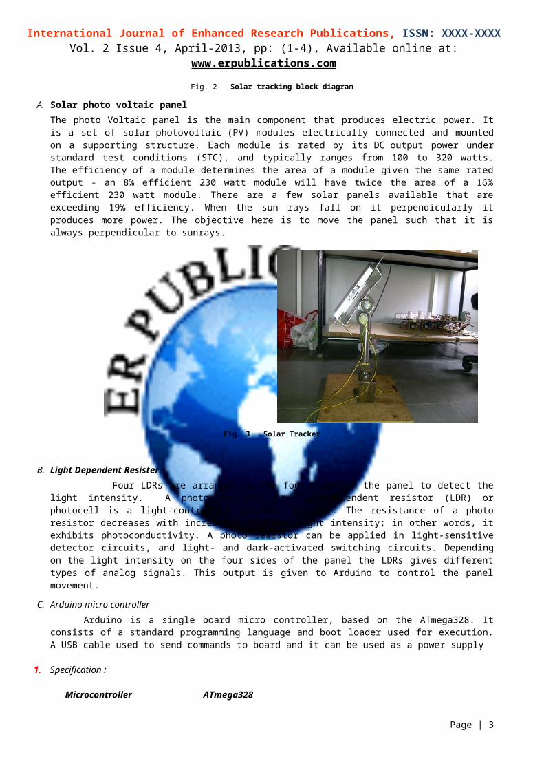
Fig. 3 Solar Tracker
B. Light Dependent Resister. Four LDRs are arranged at the four sides of the panel to detect the light intensity. A photo resistor or light-
dependent resistor (LDR) or photocell is a light-controlled variable resistor. The resistance of a photo resistor decreases
Page | 2
International Journal of Enhanced Research Publications, ISSN: XXXX-XXXXVol. 2 Issue 4, April-2013, pp: (1-4), Available online at: www.erpublications.com
with increasing incident light intensity; in other words, it exhibits photoconductivity. A photo resistor can be applied in light-sensitive detector circuits, and light- and dark-activated switching circuits. Depending on the light intensity on the four sides of the panel the LDRs gives different types of analog signals. This output is given to Arduino to control the panel movement.
C. Arduino micro controller Arduino is a single board micro controller, based on the ATmega328. It consists of a standard programming
language and boot loader used for execution. A USB cable used to send commands to board and it can be used as a power supply
1. Specification :
Microcontroller ATmega328 Operating Voltage 5V Input Voltage 7-12V Input Voltage (limits) 6-20V Digital I/O Pins 14 (of which 6 provide PWM output) Analog Input Pins 6 DC Current per I/O Pin 40 mA DC Current for 3.3V Pin 50 mA Flash Memory 32 KB (ATmega328) of which 0.5 KB used by bootloader SRAM 2 KB (ATmega328) EEPROM 1 KB (ATmega328)
Clock Speed 16 Hz
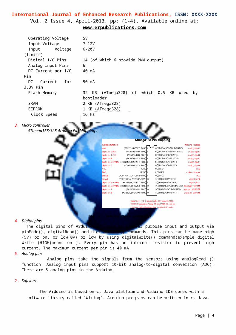
3. Micro controller ATmega168/328-Arduino Pin Mapping.
Fig. 4 Arduino micro controller4. Digital pins
The digital pins of Arduino are used as general purpose input and output via pinMode(), digitalRead() and digitalWrite() commands. This pins can be made high (5v) or on, or low(0v) or low by using digitalWrite() command(example digital Write (HIGH)means on ). Every pin has an internal resister to prevent high current. The maximum current per pin is 40 mA.
5. Analog pins Analog pins take the signals from the sensors using analogRead () function. Analog input pins support 10-bit analog-to-digital conversion (ADC). There are 5 analog pins in the Arduino.
2. Software
The Arduino is based on c, Java platform and Arduino IDE comes with a software library called "Wiring". Arduino programs can be written in c, Java.
FUNCTIONS WE WILL USE:
Page | 3
International Journal of Enhanced Research Publications, ISSN: XXXX-XXXXVol. 2 Issue 4, April-2013, pp: (1-4), Available online at: www.erpublications.com
ANALOG READ(): to read the output (analog value)of LDR
DIGITAL WRITE(): to load a 5v in a pin. That is to b connected to relay
The arduino takes the analog signals of LDRs and compares them. Depending on the compared result arduino give an instruction to relay card to move the desired value.
D. Relay card
Fig. 5 Relay connection
4-channel universal relay card works as a switch (digital switch). Arduino microcontroller controls the relay card there by switching of two motor triggers the relays such that the panel rotates to achieve maximum output.
E. Servo motor As per the fundamental operation servo motors are also same as normal motors, but with a servo mechanism is
included to achieve required performance. Servo motor is a combination of normal motor with a sensor to measure the actual output. Servo mechanism is nothing but a closed loop controlling mechanism. A servo motor can be started and stopped at any position. Simple servo motor just consists of the position sensor. In this tracking system depending on the switch of 4 channel relay card the panel rotates.
F. 555 TimerA timer 555 circuit is also used to give controlling input signals to micro controller Arduino. It will be activated in
cloudy weather conditions. It rotates the panel depending on time value.
OPERATING For example, for a dual axis horizontal and twisting solar tracking the solar panel moves in horizontal and in circular directions as shown in figures, when sensors signals are given to arduino analog pins A2,A3,A4,A5 and relay controlling pins are connected to digital pins 4,5,6,7 .the processing will be like this.
Fig. 6 solar tracking system
Page | 4

International Journal of Enhanced Research Publications, ISSN: XXXX-XXXXVol. 2 Issue 4, April-2013, pp: (1-4), Available online at: www.erpublications.com
LDR sensors detect the light intensity of the sun and Arduino compares the analog output values of LDRs. When A1 value is greater than A2. Arduino 4th pin becomes high. That means it’s giving a high signal to relay 1 of relay card. Then motor 1 moves the panel forward by given angle in horizontal direction.
In contrast to this if A2>A1 Arduino 5th pin becomes high, controller gives high signal to relay 2 of relay card. Motor moves anti clock wise. There by, the panel rotates backward.
Fig. 4 Twisting
Arduino compares the analog output values of A3,A4 LDRs. when A3 value is greater than A4.arduino 6th pin becomes high. It triggers relay 3 of relay card. Then motor 2 rotates the panel clock wise in circular direction.
When A4>A5, arduino 7th pin becomes high. That means it’s giving a high signal to relay 4 of relay card. Motor moves in anti clock wise. That means the panels rotates in anti clock wise direction in circular axis.
Thus the panel always rotes in dual axis to track the solar energy.
Fig. 7 Horizontal movement
USES OF SOLAR TRACKING By using tracking mechanism comparatively more power can be produced. CSP applications using dual axis tracking include solar power towers and dish (Stirling engine) systems. Dual axis
tracking is extremely important in solar tower applications due to the angle errors resulting from longer distances between the mirror and the central receiver located in the tower structure.
From morning to evening we can generate the electricity using solar energy whatever the sun’s direction is th Whenever LDRs cannot detect the sun’s position (light intensity in active hours is less than minimum limit)
automatically activated timer will be activated and controls the tracking as per that particular movement time.
I. EFFICEIENCY
Page | 5

International Journal of Enhanced Research Publications, ISSN: XXXX-XXXXVol. 2 Issue 4, April-2013, pp: (1-4), Available online at: www.erpublications.com
A dual axes solar tracker improves the panel output by 35 percentage which might not be useful in case of small panels but very useful in large panels where we have to rotate large amount of small panel units in the same direction.(By making a big construction) 11,2 kw dual axes tracker output 22000 Single axes tracker output 19000 No tracking involved 14000
Fig.8 Output of solar panel with respect to tracking
II. CONCLUSION
On one side we have been seeing the improving requirement of electrical energy and on the other hand improving pollution in this situation solar energy is good choice to produce power and increasing its efficiency is also important. Even through solar tracking does not affect the output of small panels, it is so helpful in improving the efficiency of large photo voltaic panels. The solar tracking system we have developed (horizontal-tilt type dual axis solar tracking) is so easy to construct and improving the efficiency of solar panel effectively.
ACKNOWLEDGMENT
We wish to acknowledge the contribution of IJERSTE on the similar topics.
REFERENCES
[1].Electrical machines by Bimbra [2]. http://en.wikipedia.org/wiki/Solar_energy[3].www.arduino.co . [4].http://www.premierpower.com/case_studies/wcwd.phph [5].http://www.hindawi.com/journals/jre/2014/629717/[6].http://htwww.naturalspublishing.com/files/published/9jx18n43q3d2ys.pdf[7].http://eds.ieee.org/education/319-introduction-to-physics-and-technology-of-solar-cells-abstract [8].http://www.ieee.org/conferences_events/conferences/conferencedetails/index.html?Conf_ID=20112 [9].http://eds.ieee.org/education/321-physics-and-technology-of-advanced-solar-cells-abstract
Page | 6