Embed Size (px)
Citation preview
8/6/2019 Paper on Use of in Situ Metallography for Plant Health Assessment Studies and Failure Investigations
http://slidepdf.com/reader/full/paper-on-use-of-in-situ-metallography-for-plant-health-assessment-studies-and 1/10
Paper No.
09012
Use of In-Situ Metallography for Plant HealthAssessment Studies and Failure Investigations
Paresh U. Haribhakti
TCR Arabia LLCKingdom of Saudi Arabia
Email: [email protected]
ABSTRACT
As a non-destructive technique, in-situ metallography is considered critical for assessing the integrityhealth of the equipment, which operates under various plant conditions. The acceptance of in-situ
microstructure assessment as a predictive maintenance approach has been dictated by the industry’s
needs for safe and reliable operations. In-situ metallography can be useful in microstructureassessments for monitoring in-service degradation of critical components of oil and petrochemical
refineries, power generation plants, fertilizers and chemical industries. In the past, inspection intervals
were based on historical experiences and engineering judgments but the recent development of in-situmetallography could prioritize the inspection locations on a risk base analysis by understanding the
damage mechanisms. Microstructure, if properly analyzed, can be utilized to find out the on-set of early
damage and corrective actions which may be initiated well in advance. A data-base for microstructuraldegradation was developed by understanding the failure mechanism and its microstructural signatures.
This paper includes case studies of microstructural degradation of components under high temperature
and high pressure. The in-situ metallography technique was discussed in detail for monitoring the plant
integrity.
1. INTRODUCTION
In-situ metallography is one of the most important NDT tools in assessing the condition and life of plant
facilities to avoid catastrophic failures and to ensure safe and reliable operations of critical engineering
equipment in power plants, petrochemical industry, fertilizer plants, cement plants, etc. Due torequirements of critical assessment of all those components under demanded working conditions, in-situ
microstructural evaluation has become an essential technique for conduction a plant integrity assessment
study. Previously, metallography was conducted by destructive means where it was required to cut-remove the sample. With advancement in the technology in development of portable equipments, the
conventional metallography has evolved as non destructive method. Now it is possible to monitorperiodically the integrity of the facilities through in-situ metallography.
The operating pressure and temperature play an important role for degradation mechanism of metals like
carbon steels and high alloy steels in the process industries. Adding alloying elements increases
component’s ability to withstand arduous process demands by improving metallurgical condition of analloy. Microstructure influences and governs properties like, Mechanical, Metallurgical, Physical and
Corrosion Resistance of an alloy. It records subtle evidences of manufacturing processes like casting,
forging, rolling and fabrication including welding. The evidences require to be decode with the help of
metallurgical knowledge, past experience and judgment, which are in form of tiny features of micro-constituents called as phases, grain shape etc. It is a result of the metallurgical processes a component
8/6/2019 Paper on Use of in Situ Metallography for Plant Health Assessment Studies and Failure Investigations
http://slidepdf.com/reader/full/paper-on-use-of-in-situ-metallography-for-plant-health-assessment-studies-and 2/10
had undergone to attain required properties. When a component is exposed to high temperature andpressure conditions its microstructure degrades. It is also influenced by operational abuses like thermal
fatigue, process up-sets, high temperature corrosion and creep, etc. All these damages get recorded in
in-situ metallography by way of change in microstructure. In-situ metallography, if properly applied canproduce valuable data, based on which forced outages can be avoided.
2. IN-SITU METALLOGRAPHY
The technique of in-situ metallography involves location selection, mechanical grinding and polishing
/electrolytic polishing, electrolytic etching or chemical etching, replication and microstructureobservations.
Equipment and consumables used in in-situ metallography are shown in Figure 1. The kit of in-situmetallography comprises of portable grinder, light grinder with variable speed controller, electrolytic
etcher/polisher, microscope and variety of consumables. The consumables are listed as self adhesive
polishing papers of different grit size, self adhesive sylvet cloth, solvents, water bottles, diamond paste,
suspended alumina, electrolytes and replica films.
To get the maximum benefit from this technique, selection of the location to gather microstructuredetails is of paramount importance. The selection has to be based on the judgment of the experienced
metallurgist who has adequate knowledge of the degradation mechanism pertaining to the system.Initially, small area is mechanically polished with rough grinding to remove oxide scales from the
surface. With the use of self adhesive papers from course to fine grain size about 1000 grit finish,
progressive mechanical polishing is done. Thereafter, suspended alumina is used with silvet cloth forfine polishing up to 5 micron finish. Finally, diamond paste is used for polishing to attain scratch free
mirror like finish. Either mechanical or electrolytic polishing is adopted for the final polishing process.
Figure 1 shows photographs of in situ metallography equipment.
Then the etching process is carried out to develop contrast to differentiate the micro-constituents
present. Normally, one to two etch-polishing are provided to get good microstructure without anydisturbance of the surface. It is essential to view the microstructure with a portable optical microscopehaving magnification up to 400X prior to replication. Replication is a last stage where wet cellulose
acetate tape is pressed on the etched surface. Gentle pressure is applied so that the microstructure
diligently gets transferred on the tape. It is then viewed under optical microscope by an experiencedmetallurgist. The tape can be self refractive or it can be painted. There are different methods of replica
techniques - castrastic techniques or extraction replica is some time used. Further enhancement in the
contrast is achieved by gold sputtering and then replica structure can be viewed under scanning electron
microscope for high resolutions. The main advantage of the extraction replica technique is carbideprecipitated at elevated temperatures can be found out. Figure 1 shows the flow chart of replication
process.
3. DAMAGE MECHANISMS
Commonly observed damage mechanisms in carbon steels and alloy steels are as follows:
3.1 Graphitization
Prolonged exposure of plain carbon steel to a temperature around 400C decomposes pearlite into ironand graphite and thereby reduces the mechanical strength. It can severely embrittle the steel when the
graphite nodules form in planar.
8/6/2019 Paper on Use of in Situ Metallography for Plant Health Assessment Studies and Failure Investigations
http://slidepdf.com/reader/full/paper-on-use-of-in-situ-metallography-for-plant-health-assessment-studies-and 3/10
3.2 Degradation of Pearlite & Bainite
Prolonged high temperature exposure of carbon and low- alloy steel material, result in pearlite coloniesgetting transformed to spheroids. Chromium retards the process of spheroidization. In some of the
power plant components having bainite in the microstructure is essential for the enhancement of creep
resistance. Nevertheless, bainite microstructure also degrades into globular carbides in ferrite after
prolonged exposure of the component at elevated temperatures.
3.3 Creep Damage
Time related, temperature dependent deformation under stress is known as creep. The degradation is
stage wise and it can reveal the initiation in the microstructure as creep voids, orientation of creep voids
and micro cracks.
3.4 Hydrogen Attack
Boiler feed water and steam corrosion and hydrogenated atmosphere can lead to formation of nascenthydrogen, some of the hydrogen atoms will then diffuse in the steel, where they react with iron carbide
to form ferrite and methane gas. This will lead to micro cracks and lowering of the strength of material.
3.5 Thermal Fatigue
Thermal cycling having repetitive expansion and contraction develop thermal stresses that may
eventually result into fatigue cracks. It is common with rotor shaft and batch type of reactors wherethere is wide variation of temperature.
3.6 High Temperature Oxidation
Oxidation occurs at the grain boundaries and then gradually penetrates inside. The thickening of grain
boundaries in plain carbon steel is easily noticed with its differed response to etching.
3.7 Decarburization
Removal carbon from the surface and edges is normally seen as formation of ferrite at the expense of pearlite.
3.8 Grain Coarsening
Prolonged high temperature exposure will result in grain boundary coarsening and thereby the strength
of the material is reduced.
3.9 Intergranular Corrosion
The weakening of the grain boundary takes place due to preferential corrosion on account of deposition
of chromium carbides. Depletion of chromium takes place in the vicinity where the corrosion resistancedrops drastically in a highly localized region of the grain boundary.
3.10 Stress Corrosion Cracking
Presence of internal stresses in stainless steel especially at welded joints or at cold worked regions can
induce network of fine micro cracks when either the steel is sensitized or surrounding is conducive to
8/6/2019 Paper on Use of in Situ Metallography for Plant Health Assessment Studies and Failure Investigations
http://slidepdf.com/reader/full/paper-on-use-of-in-situ-metallography-for-plant-health-assessment-studies-and 4/10
having chloride and other ions. It is one of the most heinous kinds of degradation mechanisms that canlead to catastrophic failures without any warning.
3.11 Sigma Phase
Sigma phase is an inter-metallic compound, non magnetic in nature which normally forms where the
steel is exposed in the temperature range of 580-960°C. The presence of delta ferrite makes it more
vulnerable for sigma phase formation. It is brittle in nature and undergoes contraction when it is
formed. Thus, micro cracks are likely to develop and steel becomes highly brittle.
3.12 Carbide Precipitation
The precipitation of alloy carbide takes place at the grain boundaries making the steel brittle with
reduced corrosion resistance.
Degradation by way of second phase formation is also more common in Nickel base and super alloys.
The technique of in-situ metallography is also applicable Titanium, Aluminum and copper base alloys.
However, bulk usage in industry revolves around steel and stainless steel.
Figures 1-4 show some of the microstructure damages and normal structures observed with the help of In-Situ Metallography.
4. CASE STUDIES
4.1 Sigma Phase Identification through In-Situ Metallography
Stainless steels are normally used in refineries in the range of service temperature where they are
susceptible to sigma phase formation. Normally, the temperature ranges between 580-960°C.Corrosion resistance is drastically reduced and its formation leads to brittle failure of the components
during start up and shut down of the plant. In-situ metallography is effectively used to find out presenceof sigma phase with electrolytic etching. If it is finely distributed spread uniformly in themicrostructure, then it is less harmful. However, if sigma phase is concentrated in form of lumps it is
highly detrimental – more so when inter connected. During shut downs, it can trigger onset of corrosion
finally leading to leakage. The percentage of sigma phase can be calculated using automatic imageanalyzer software that aids in taking a decision whether the component is to be replaced or used further.
Figures 6 & 7 show the microstructures indicating copious sigma phase formation after 8 years of
service of SS 304H pipe in FCC service of refinery. 15-20% of sigma in the weld metal was judged as
the criteria that increases the susceptibility towards cracking. However, the decision of replacementdepends on the morphology of the sigma phase and cracking tendency of the weld.
4.2 Reformer Tubes
Reformer tubes are used in fertilizer industries, refineries and petrochemical industries either for
hydrogen generation or reforming of hydrogen along with the steam. The tubes act as individual
reactors for the reforming process. The specific failure mechanism involves creep generated mid wallfissures that progress towards the OD. Mid wall fissures that were noticed under conventional NDT test
like UT, Radiography and Creep determination by OD measurements with judicious approach. In-situ
metallography was used to determine whether the tubes can be used further or be retired immediately.Figures 8 & 9 are the selected microstructures of in-situ metallographs from a reformer tube of HP
modified alloy; comparing control virgin tube microstructure versus the presence of micro cracks in a
8/6/2019 Paper on Use of in Situ Metallography for Plant Health Assessment Studies and Failure Investigations
http://slidepdf.com/reader/full/paper-on-use-of-in-situ-metallography-for-plant-health-assessment-studies-and 5/10
used tube having 12 years of service completed. This indicated the final stage of creep life and the tubewas retired from the service in order to avoid failures during service.
4.3 Fire Damage Assessment
With all the precautions and safety measures, accidents do take place in process plants. Accidental fire
damage is more common in refineries and petrochemical industries. The carbon and alloy steel
components are normally analyzed by replica microstructure analysis. The components having intact
pearlite are allowed for further use. Those having complete spheroidization of the pearlite arerecommended for replacements. Those having partial spheroidization of the pearlite are recommended
for further use with periodic monitoring through in-situ metallography. It requires great depth of metallurgical knowledge to judge the estimation of temperature based on physical metallurgy.
4.4 Remaining Life Assessment through Replica SEM for Boiler Components
Boiler pressure parts like super heater tubes, steam pipes and headers are operating in the creep range
and they are designed for certain minimum lifetime. These components deteriorate continuously during
the service, as a result of time dependent material degradation process like creep, fatigue, corrosion andoxidation. The limiting factors for the components operating at high temperature and pressure are creep
life. Creep life is considered exhausted when it reaches the macro cracks through cavitation stage.The damage takes place in four successive stages formation of cavities, alignment of creep cavities,
micro crakes and macro cracks. One can find out the life fraction consumed by identifying theprevailing stage in the microstructure. The successive stages are no creep cavities, isolated creep
cavities, oriented creep cavities and the final stage of micro-cracks. Next monitoring interval is based
on the level of degradation observed. Observing under SEM after gold sputtering can have most reliable judgments. Figures 10 & 11 are SEM micrographs of the main steam line showing oriented creep
cavities with initial stage of micro cracks. It was recommended to monitor the cracks after one year
through in-situ metallography and start planning for the replacement in next two years.
4.3 Sensitization in Stainless Steel
Austenitic Stainless steels are extensively used especially for high temperature and corrosion resistanceapplications. Carbide precipitation is more common while it undergoes processes like hot working and
welding and during operation. Alloys are supplied in solution annealed condition where the carbon
remains completely dissolved in austenite matrix and there is no carbide precipitation at the grainboundaries for better corrosion resistance. During the course of service or improper manufacturing it
may undergo damage by way of precipitation of carbides at the grain boundaries. This can be easily
detected by adopting in-situ metallography technique which can also assess the extent of damage.
Figures 12 & 13 show presence of chromium carbide precipitations at the grain boundaries and is termedas ditch structure. Such material is susceptible for IGC (Inter-granular corrosion) and IGSCC (Inter-
granular stress corrosion cracking) attack under favorable conditions.
5. CONCLUSIONS
In situ metallography when properly applied can generate valuable information for safe, reliableoperation of process plants. Periodic monitoring of microstructure can generate confidence in operation
and provides useful guidelines for timely replacement decisions or helps life extension evaluations.

8/6/2019 Paper on Use of in Situ Metallography for Plant Health Assessment Studies and Failure Investigations
http://slidepdf.com/reader/full/paper-on-use-of-in-situ-metallography-for-plant-health-assessment-studies-and 6/10
6. REFERENCES
1) ASM Handbook Vol.: 9: Metallography and Microstructure.
2) R. B. Setterlund and W. M. Buehler: Nondestructive Metallography, Metallurgical Consultants,
Inc., Houston, Texas.
3) R Viswanathan: Damage Mechanisms and Life Assessment of High-temperature Components.ASM International, 1989.
4) J. D. Parker& B. Wilshire: Non-destructive Life assessment of High temperature Components andWeldments, Journal of Press vessel and Piping 50 (1992) 337-347
5) B. Neubuer & U. Wedel: NDT Replication Avoids Unnecessary Replacement of Power Plant
Components. Power Engineering May1994.
6) J. L. Hau: Assessment of Fire Damage to Pressure Vessels in a Refinery Unit., Corrosion -
May 1993.
8/6/2019 Paper on Use of in Situ Metallography for Plant Health Assessment Studies and Failure Investigations
http://slidepdf.com/reader/full/paper-on-use-of-in-situ-metallography-for-plant-health-assessment-studies-and 7/10
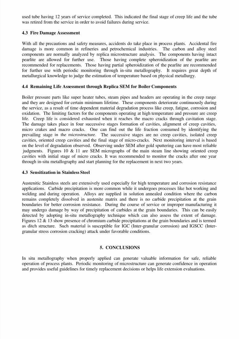
Figure 1 – Shows the Flow Chart of In-Situ Metallography Process
MECHANICAL FINISH UP TO 600 grit (Through 60, 80, 120, 240, 320, 400, 600 grit.)
ELECTROLYTIC POLISHING
LOCATION SELECTION
VISUAL EXAMINATION
ROUGH GRINDING
MANUAL POLISHING
MECHANICAL POLISHING UP TO 1000 grit THROUGH 800, 1000 grit.
POLISHING WITH DIAMOND PASTE (5 AND 1)
ALUMINA POLISHING (GRADE I, II AND III.)
ETCHING
MANUAL ELECTROLYTIC
MICROSTRUCTURE VIEWING
REPLICATION
RECORDING OF DETAILS
8/6/2019 Paper on Use of in Situ Metallography for Plant Health Assessment Studies and Failure Investigations
http://slidepdf.com/reader/full/paper-on-use-of-in-situ-metallography-for-plant-health-assessment-studies-and 8/10
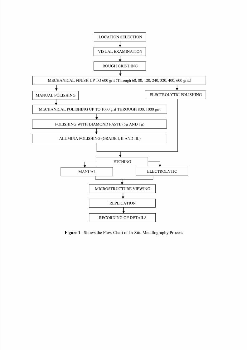
Figure 2 – The Equipment Used for In-Situ Metallography
with Electrolytic Etcher/Polisher, Portable Grinder, Microscope, etc.
Figure 3 – Shows the Replicated Microstructure
of Spheroidized Structure of SA 335 P11 Material,Exposed in the Service for 15 Years (400X)
Figure 4 – Shows Microstructure of Plain Carbon Steel
Material Showing the Grain Boundary Oxidation,Exposed to an Accidental Fire (400X)
Figure 5 – Replicated Microstructure of Cr-Mo-V,
HP Rotor Shaft Showing Bainitic Structure and
Prior-Austenitic Grain Boundary (100X)
Figure 6 – Replicated Microstructure of 304 SS
Reactor Showing Trans Granular Stress
Corrosion Damage at HAZ (400X)
8/6/2019 Paper on Use of in Situ Metallography for Plant Health Assessment Studies and Failure Investigations
http://slidepdf.com/reader/full/paper-on-use-of-in-situ-metallography-for-plant-health-assessment-studies-and 9/10
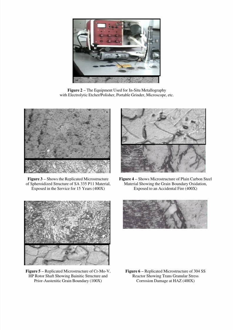
Figure – 6 PM (400X) Figure – 7 Weld (400X)
Figures 6 & 7 are microstructures of SS 304H material showing presence of sigma phase formation at the grainboundaries and within the grains of parent metal and at inter-dendrite regions of weld metal.
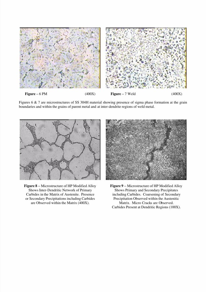
Figure 8 – Microstructure of HP Modified Alloy
Shows Inter-Dendritic Network of Primary
Carbides in the Matrix of Austenite. Presence
or Secondary Precipitations including Carbides
are Observed within the Matrix (400X).
Figure 9 – Microstructure of HP Modified Alloy
Shows Primary and Secondary Precipitates
including Carbides. Coarsening of Secondary
Precipitation Observed within the Austenitic
Matrix. Micro Cracks are Observed.Carbides Present at Dendritic Regions (100X).
8/6/2019 Paper on Use of in Situ Metallography for Plant Health Assessment Studies and Failure Investigations
http://slidepdf.com/reader/full/paper-on-use-of-in-situ-metallography-for-plant-health-assessment-studies-and 10/10
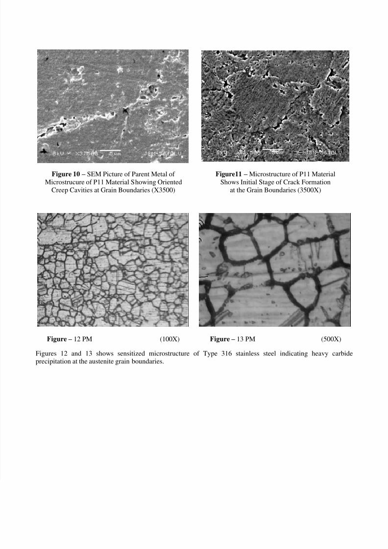
Figure 10 – SEM Picture of Parent Metal of
Microstrucure of P11 Material Showing Oriented
Creep Cavities at Grain Boundaries (X3500)
Figure11 – Microstructure of P11 Material
Shows Initial Stage of Crack Formation
at the Grain Boundaries (3500X)
Figure – 12 PM (100X) Figure – 13 PM (500X)
Figures 12 and 13 shows sensitized microstructure of Type 316 stainless steel indicating heavy carbideprecipitation at the austenite grain boundaries.