Embed Size (px)
Citation preview

Paper No. WAC-67Structural Concepts Study of Non-circularFuselage Configurations
Vivek MukhopadhyaySystems Analysis BranchAeronautical Systems Analysis DivisionMS 248, NASA Langley Research CenterHampton, Virginia 23681-0001
SAE/AIAA World Aviation CongressOctober 22-24, 1996
Los Angeles, CaliforniaFor permission to copy or republish, contact the American Institute of Aeronautics andAstronautics, 1801 Alexander Bell Dr. Suite 500, Reston, VA 22091

1
Structural Concepts Study of Non-circular Fuselage Configurations
Vivek Mukhopadhyay*Systems Analysis Branch,
Aeronautical Systems Analysis DivisionNASA Langley Research Center, Hampton, VA
ABSTRACT
A preliminary study of structural concepts for non-circular fuselage configurations is presented. For anunconventional flying-wing type aircraft, in which thefuselage is inside the wing, multiple fuselage bays withnon-circular sections need to be considered. In aconventional circular fuselage section, internal pressureis carried efficiently by a thin skin via hoop tension. Ifthe section is non-circular, internal pressure loads alsoinduce large bending stresses. The structure must alsowithstand additional bending and compression loadsfrom aerodynamic and gravitational forces. Flat andvaulted shell structural configurations for such anunconventional, non-circular pressurized fuselage of alarge flying-wing were studied. A deep honeycombsandwich-shell and a ribbed double-wall shellconstruction were considered. Combinations of thesestructural concepts were analyzed using both analyticaland simple finite element models of isolated sectionsfor a comparative conceptual study. Weight, stress, anddeflection results were compared to identify a suitableconfiguration for detailed analyses. The flat sandwich-shell concept was found preferable to the vaulted shellconcept due to its superior buckling stiffness. Vaulteddouble-skin ribbed shell configurations were found tobe superior due to their weight savings, load diffusion,and fail-safe features. The vaulted double-skin ribbedshell structure concept was also analyzed for anintegrated wing-fuselage finite element model.Additional problem areas such as wing-fuselagejunction and pressure-bearing spar were identified.
1. Introduction
Fuselage configuration and structural design of a verylarge transport aircraft is a major task. For such adesign, extensive experience and database exists1 forconventional aircraft. For an unconventional aircraftsuch as a flying-wing, in which the fuselage is part ofthe wing, partially circular or non-circular sections needto be considered. Efficient structural design of such anunconventional non-circular pressurized fuselageimposes a special challenge since extensive experienceand databases do not exist. Moreover, during theconceptual design stage, loading conditions, materialproperties, detailed configuration and structural---------------------------------------------------------------* Associate Fellow, AIAA
dimensions of the fuselage are usually not known.Hence, in this preliminary structural analysis stage, it isoften convenient to assume a representativeconfiguration with appropriate dimension andundertake a comparative study using simple finiteelement modeling and analysis2 for a typical set ofloads and material properties. Although this proceduremay initially lead to a conservative design, it oftenprovides guidance towards a better configurationthrough comparative weight and stress analysis, andcould be used to identify new concepts which mayimpose less weight penalty to this unconventionalconstruction in an otherwise efficient flying wing withaerodynamic advantages.
First, basic design issues of partially circular and noncircular load-bearing pressure vessels were discussed.Based on their relative advantages and disadvantages,two non-circular pressure vessel concepts were selectedfor analysis: a) a flat sandwich shell concept and b) avaulted sandwich shell concept, both with a honeycombcore. Simple structural finite element models (FEM)were used for displacement and stress analysis,followed by a limited sizing study. Next, an alternateconcept was investigated for weight reduction. In thisconcept, the honeycomb was replaced by a double-skinshell with vertical spanwise and chordwise ribstiffeners. Both the flat and vaulted double skin shellconstruction were analyzed and compared. Finally, oneintegrated cantilever wing-fuselage configuration usingthe vaulted ribbed shell concept was analyzed.
2. Basic Issues
For a very large conventional subsonic transport, ascaled-up fuselage with a double-deck circular crosssection is often considered as shown in Fig. 1, wherethe shaded area is the pressurized section. When thecross section of a fuselage is circular, the internalpressure is resisted efficiently by the thin skin via hooptension. The hoop stress, based on force equilibrium, isgiven by σ=pr.D/2t, where pr is the internal pressure, Dis the diameter and t is the skin thickness. Any bucklinginstability is prevented by stiffening the thin skin withframes and stringers. The fuselage end pressure andconcentrated loads from landing gear, engine and wingmount are carried by heavy bulkheads.

2
Fig. 1. Conventional circular fuselage.
For a very large flying-wing type transport, it may benecessary to place several non-circular fuselage bays intandem locations inside the wing. In such a situation,the fuselage could be built as a multi-bubble partially-circular section as shown in Fig. 2, where the shadedarea represents the pressurized section. Then the outerskin can carry pressure efficiently by hoop stress andthe cabin walls can be used to balance the verticalcomponent of the hoop stress of adjacent bubblesections as shown by arrows in Fig. 2. In general, if thefuselage section is non-circular, any internal pressureload would also induce substantial bending in thestructure. In addition, the tandem fuselage must alsowithstand additional spanwise bending andcompression load like a regular wing. Bending loadalong with any asymmetry usually induce large stress atthe bubble joints.
Fig. 2. Multi-bubble section and stress balance.
Vaulted Sandwich Shell : For a very large flying wing,the multi-bubble fuselage must be placed inside a wingwith smooth aerodynamic outer surface. A simplifiedcross -section sketch is shown in Fig. 3 where theshaded area represents the pressurized section. Thistandem fuselage configuration requires a double-skinconstruction which could be stiffened or filled withlight honeycomb filler in between to transmit theexternal aerodynamic load from the outer skin, and toprevent local buckling. This makes a load-bearing non-circular pressurized fuselage construction veryinefficient and imposes excessive weight penalty due tothe high volume of honeycomb filler material. It is alsonot very attractive from a fabrication complexityviewpoint.
Fig. 3. Multiple tandem vaulted shell fuselage sectionsinside flying wing.
Flat Sandwich Shell : A possible alternative is to useuniformly deep honeycomb or stiffened frameconstruction which follows the outer aerodynamiccontour as shown in Fig. 4. Although such nearly flatshells are not suitable for carrying large internalpressure, and have numerous highly stressed Tjunctions, with careful design this concept might bevery attractive due to the simplicity of construction, andreduced volume of honeycomb filler material. Thisconfiguration also does not need additional flooringwhich is essential for a partially circular or vaulted shellconstruction shown in Fig. 3. Hence, it would beinteresting to investigate this alternative structuralconfiguration.
Fig. 4. Uniform depth flat shell fuselage.
Advantages and Disadvantages : Both of theseconfigurations have other advantages anddisadvantages. The upper section of the vaultedfuselage is under compressive loading due to thecumulative bending moment from the wing load, andcan be assumed to act like a beam-column as shown inFig. 5a. The mid section, which carries a large bendingmoment, possesses the least bending stiffness. It mightbe possible to choose a shallow cylindrical arc for thevaulted contour to provide larger section moment ofinertia at mid span, and do an extensive optimizationstudy to determine a span-to-rise ratio and then selectthe best beam-column. However, a uniformly deephoneycomb shell structure might be better suited toresist such a combined bending and compressive load inthis situation as shown in Fig. 5b, due to its superiorbuckling stiffness.
Double-skin ribbed shell : In order to combine theadvantage of the partially circular section and removethe disadvantages of sandwich construction, anotherpossible alternative was considered. If the honeycomb

3
pressure
Lift
Lift
pressureFig. 5. Idealized loading on upper-section of a a)vaulted shell; and b) uniform depth shell fuselage.
core could be replaced with stiffening ribs and properlyspaced to prevent local buckling, then this configurationwould be significantly lighter. Such construction ismuch like a double-skin pressure bulkhead of a tankership, and could be well suited to prevent fatigue crackpropagation and increase buckling rigidity. In addition,in case of an inner-skin pressure leak, the double skinvaulted shell concept could be designed to be fail safe,because it would act like a suspension bridge, where theouter aerodynamic skin would take the pressure load,which would be transmitted through the ribs to put theinner vaulted-skin in tension, like a catenary. However,fabrication and splicing of such a structure could be amajor problem for both conventional and compositeconstruction. This double skin ribbed shell concept wasanalyzed for both the vaulted- and flat- shellconfigurations and compared with the sandwichconcept results.
Other problem areas : There are several other problemareas which became apparent during this analysis. If theend of the fuselage is terminated at the wing front orrear spar, the spars must also be designed to withstandboth pressure and bending. The most outboard sectionwhere the unpressurized outer wing is attached,appeared to be a highly stressed critical structure. Thusstresses at the wing-fuselage and wing-spar junctioncould be a major problem. Of course, other issues likelocal crippling, damage tolerance, crack propagation,splicing, moisture egress, corrosion, cut-out, fabricationand maintenance should also be addressed.
Two-dimensional beam-column analysis : Some initialsizing, load, stress and deflection data can be obtainedusing the analytical nonlinear beam-column solution3
for a simplified configuration of the cabin roof shownin the sketch, where P is axial load, pr is normal cabinpressure, l is column length, t is thickness of face skin,
PPpr
d l
t
t
and d is depth of honeycomb core. Assuming that thebending area moment of inertia of the sandwich beam
with core depth d, and width w is given by I=2tw(d/2)2,the critical bucking load Pcr for simply-supported
boundary condition is given by Pcr=π2EI/l2. Defining
µ=(π/2)(P/Pcr)0.5, the maximum deflection, bendingmoment and bending stress at mid span are given by
zmax = 5pr.l4
384EI
12(2secµ − 2 − µ 2 )5µ 4
Mmax = pr.l2
8+ 5pr.l4
384EI
12(2secµ − 2 − µ 2 )5µ 4 P
and
σmax = Mmaxd
2I where µ = π
2P
Pcr
Note that the expressions are singular at P=Pcr. Using acore depth of d=10 inches, face skin thickness of t=1/8
inch, Young's modulus of E=10x106 psi, beam lengthof l=150 inches, transverse pressure of pr=18.6 poundsper square inch (psi), the mid-span deflection Zmax,deflection shape Z, mid-span bending moment Mmaxand bending stress σmax were computed and plotted inFig. 6 as a function of axial load P from 1 to 5000pounds, for a simply-supported beam of unit width. Theplot of deflection Zmax and stress σmax indicate thatwhen the axial load P is 5000 pounds per inch, mid-span deflection Zmax=0.2 feet, and the maximumbending stress σmax=51450 psi. Although the bucklingload ratio P/Pcr=0.182, the nonlinear in-plane effect ofadditional bending moment caused by the deflectionand axial compressive load is to produce 23 percenthigher stress compared to the linear value of 41850 psidue to the transverse pressure load. If the depth of thebeam is 5 inches and P=5000 lb/inch, then P/Pcr is0.73, Zmax is 2.42 ft and σmax is 316,000 psi. If thedepth of the beam is 5 inches and P=1000 lb/inch, thenP/Pcr is 0.146, Zmax is 0.766 ft and σmax is 98,410psi. These simple calculations provide a basic idea ofsizing for a typical composite material with Young's
modulus of E=10x106 psi and yield stress of 50000 psi.

4
0 5 100
0.2
0.4
Z( ).5000 lb
Z( ).10000 lb
xa) Beam deflection shape (feet) vs. P (lb)
0 5000 1 1040.1
0.2
0.3
Zmax( )P
Pb) Mid Span deflection (feet) vs. P (lb)
0 5000 1 1044000
6000
8000
Mmax( )P
Pc) Mid span bending moment (ft-lb) vs. P (lb)
0 5000 1 1046 106
8 106
1 107
σmax( )P
Pd) Mid-span bending stress (psf) vs. P (lb)
Fig. 6. Beam deflection shape Z, mid-span deflectionZmax, bending moment Mmax and bending stressσmax variation with axial compressive load P.
For a typical face skin thickness of 1/8 inch, the 150inches long simply-supported beam depth must beabout 10 inches, to sustain a compressive load of 5000lb/inch and transverse pressure of 18.6 psi. A simply-supported beam which is 5 inches deep can barelysustain a compressive load of 1000 lb/inch when thetransverse pressure is 18.6 psi. This idealized studyindicates that a 5-inch deep honeycomb beam may notbe adequate. Hence, in the 3-D finite element analysisto be described next, a conservative 10-inches deep
shell construction was considered, although for actualboundary condition and fully stressed design, the depthcould be between 5 and 10 inches.
3. Structural configurations
Since the structural details of the entire wing-fuselagecombination are usually not known in the conceptualdesign stage, the comparison study was accomplishedby first analyzing two simple configurations, whichrepresented an outer bay of the wing-fuselagecombination shown in Figs. 3 and 4. The cross sectionsof the fuselage bay for the two proposed structuralconfigurations, namely a) uniform depth flat shell, andb) vaulted shallow cylindrical shell are shown in Fig. 7.For each of these configurations, both the c)honeycomb sandwich shell, and d) stiffened double-skin shell structural constructions were investigated.
200
150 150
160
175 R
10 4
FLAT SHELLCONCEPT
VAULTED SHELLCONCEPT
160
Fig. 7. Cross sections of a) Uniform-depth flat shell,and b) Vaulted shell fuselage concepts.
Sandwich Shell : All dimensions shown in Fig. 3 weretypical for a six-passenger abreast, single-aisle fuselagebay, but otherwise arbitrary. Based on the 2-D beam-column analysis in section 2, the flat sandwich shellswere assumed to have uniform core depth of 10 inches,with 1/8 inch thick composite face skins. The vaultedcylindrical shells were assumed to have a radius of 175inches and the center was placed such that the corethickness varied between 20 inches at the cabin sidewall to 4 inches at mid-cabin roof. This providedapproximately the same core volume as a uniform 10-inch depth flat honeycomb sandwich shell.
Pressure Bearing Spars : The fuselage bay is assumed tohave a trapezoidal planform with its ends at the frontand rear main spar of the swept flying wing. Therefore,the front and rear spars must also carry the cabinpressure load. The pressure-bearing part of the sparwere assumed to have a sandwich structure with a 10-inch thick honeycomb core and 1/8 inch thick face skin.Although the mid-deck floor carries only passenger

5
load and could have a conventional stiffened plateconstruction, they were assumed to have the sameuniform 10-inch deep honeycomb sandwichconstruction like the pressure bearing spars, for auniform conservative design.
Simply-supported boundary conditions : Initiallysimply-supported boundary conditions were analyzedfor an isolated section, in order to evaluate their effects.The fuselage section was assumed to be simplysupported at cabin top and bottom edge at inboard sidebut were unrestrained at the outboard side. Thisboundary condition may be realistic for the flat shellconcept shown in Fig. 4, where the T-junctions betweencabins may not have sufficient rigidity in rotation.However, as a part of the overall flexible wing, theoutboard section side generally translates upward withvery small rotation. Thus in later analysis, partiallyclamped boundary conditions were used as describednext.
Clamped boundary conditions : The simply-supportednodes at the cabin top and bottom edge at inboard sideswere restrained from rotation about chordwisedirection, as shown in Fig. 8. The corresponding nodesat the outboard sides were only restrained in rotationabout chordwise direction. The outboard side wasotherwise free to translate. Although these twoboundary condition assumptions were nonconservative,they were deliberately chosen in order to identifyregions of large deflections and stresses whereadditional buckling analysis would be needed. Ofcourse, the outcome of any comparison using isolatedcomponents of fuselage would be dependent on theassumed boundary conditions at the section ends. In
order to resolve this issue, a combined half wing andfuselage idealized structure was modeled and analyzedusing clamped boundary condition at the plane ofsymmetry. This will be discussed later in the paper.
Finite Element Model and Meshing : A desktop
computer based finite element analysis software2 wasused primarily for its rapid interactive modeling andpost processing graphic facilities. The fuselage skinsurface was modeled by four node flat plate elements.The honeycomb core was modeled by 3-dimensionaleight-node solid elements. Due to computer memorylimitation, initially a coarse 8x4x5 mesh finite elementmodel was used for comparative analysis of the twoconfigurations shown in Fig. 7. Later, a less coarse16x6x7 mesh 1340 element model as shown in the Fig.8 was used for obtaining better stress and deflectionvalues. However the analysis does not take into accountnonlinear effects or guarantee deflection or stressconvergence and should be used only for comparisonpurposes.
Material Properties : Isotropic. In the initial analysis, allface skins were assumed to be 1/8-inch thick isotropicgraphite epoxy composite material with 96 lb/cuft
density, with a Young's modulus of E=10x106 psi, and
a shear modulus of G=3x10⁶ psi. The allowable tensilestress was assumed to be 50,000 psi. The Nomexhoneycomb core material was assumed to have aYoung's modulus of E=20,000 psi, shear modulus ofG=7000 psi, with a density of 3.1 lb/cuft. The allowableshear stress was assumed to be 70 psi.Orthotropic. In the latter limited sizing study, a 12percent reduced thickness skin and a light density (1.6
No translationno rotation about x
no rotationabout x
No translationno rotation about x no rotation
about x
x (down stream)
y (spanwise)
z (up)
FLAT SHELL VAULTED SHELL
Fig. 8. Clamped boundary conditions and 1340 element 16x6x7 mesh description.

6
lb/cuft) core honeycomb were used in an attempt toreduce the weight. The following typical orthotropicmaterial properties were assumed for the composite
sandwich skin: Young's modulus Ex=9x10⁶ psi,
Ey=5x10⁶, Gxy=2x10⁶ psi, Poisson's ratio ν=0.4, andallowable tensile stress of 50,000 psi. The highermodulus direction was aligned spanwise. The lightaluminum honeycomb core properties were as follows:Young's modulus Ex= Ey=300 psi, Ez=30,000 psi,shear modulus Gx y =200 psi, Gxz=12,000 psi,G y z =20,000 psi, Poisson's ratio ν x y = 0 . 3 ,νxz=νyz=0.05. The allowable stresses in compressionand shear were 80 psi and 40 psi, respectively.
Loads : The critical flight condition for limit load wasassumed to be a 2.5g maneuver at maximum takeoffweight. A typical bending moment, shear force andtorque distribution based on elliptic spanwise loadingon a swept cantilever beam were determined for thecritical load case. The limit loads at the fuselage section
were estimated to be: bending moment 27x106 ft-lb,
shear load 25x104 lb, and torque 13x106 ft-lb, at theinboard side of the fuselage section. These loads weremultiplied by a safety factor of 1.5 to obtain ultimatedesign load. For finite element analysis purposes,bending moments were converted to equivalent tensionand compression forces at the upper- and lower-surfaceskin element nodes. The equivalent runningcompressive force on upper surface was close to 4000lb/inch for a 625-inch long fuselage. The shear andtorque loading were converted to equivalent forces atthe appropriate element nodes. The equivalent nodalforces due to bending, shear, torque and pressure
loading for the vaulted shell configuration are shown inFig. 9. The design ultimate cabin pressure differential atcruise condition was assumed to be 18.6 psi whichincluded all safety factors. The mid-deck floor loadingat 2.5g was assumed to be 0.625 psi. The aerodynamicpressure and cavity pressure loads on the fuselagesection were neglected compared to the 18.6 psiultimate cabin pressure for the fuselage sectionanalyses. The outside surface approximate aerodynamicpressure varying from 1.2 psi to 4 psi were included forthe integrated wing-fuselage analyses.
4. Conceptual Structural Analysis
The conceptual structural analysis was executed firstwith an initial set of data. These results were then usedto guide the next stage of analysis. The four analysisstages were as follows.
1. Analyze two concepts: a) Flat sandwich shell, and b)Vaulted sandwich shell construction, using isotropicmaterial with 1/8th inch thick skin and heavyhoneycomb core using a 8x4x5 mesh, 488 elementmodel. Both the simply-supported and clampedboundary conditions were investigated.
2. Conduct limited sizing study, using orthotropicadvanced composite face material with a 0.11 inchthick skin, light honeycomb core for the a) Flatsandwich shell, and b) Vaulted sandwich shellconstruction, using a 16x6x7 mesh, 1340 elementmodel.
3. Investigate an alternate ribbed shell concept toeliminate the honeycomb for weight reduction using a)Flat double-skin ribbed shell model with 16 spanwise
130,000 lb@2 nodes for torque
-71500 lb@34 nodes(compression)
71500 lb@34 nodes(tension)
-3400 lb shear@102 nodes
pressure0.625 psi
18.6 psi
pressure18.6 psi
160,000 lb@2 nodes for torque
160,000 lb@2 nodes for torque
130,000 lb@2 nodes for torque
77,800 lb@34 nodes(tension)
-77,800 lb@ 34 nodes(compression)
3700 lb shear@ 102 nodes
Fig. 9. Equivalent load application on element nodes of vaulted shell configuration for16x6x7 mesh model.

7
and 1 chordwise rib (16x6x7 mesh), and b) Vaulteddouble-skin ribbed shell model with 8 spanwise and 4chordwise ribs (8x4x5 mesh)
4. Finally, analyze a combined cantilever wing-fuselagefinite element model using the vaulted double-skinribbed shell configuration with pressurized fuselageinside flying wing and a basic outer-wing structure.
The resultant displacements from the stage 1 analysisusing isotropic material properties, heavy honeycomb
core, and 8x4x5 meshing are shown in Figs. 10 and 11.The displacements of the two structural configurationsare shown in Fig. 10 for the simply-supported boundarycondition. The deflections at the mid-cabin roof of theflat sandwich shell are consistent with the earlier 2-Danalysis. The deflections for the vaulted sandwich shellare, in general, almost twice for the same load.
The displacements for the clamped boundary condition(Fig. 8) are shown in Fig. 11, which indicate that theeffect of clamped boundary condition is much more
6
3
0
12
6
0
FLAT SANDWICH SHELL VAULTED SANDWICH SHELL
Displacement, inches
Fig. 10. Displacement vectors at maximum cabin pressure 18.6 psi at 2.5g for simply-supported boundary condition (isotropic material, heavy core, 8x4x5 mesh)
3.0
1.5
0.0
VAULTED SANDWICH SHELLFLAT SANDWICH SHELL
Displacement, inches
3.70
1.85
0.0
Fig. 11. Displacement vectors at maximum cabin pressure 18.6 psi at 2.5g for clamped-boundary condition (isotropic material, heavy core, 8x4x5 mesh).
8
significant for the vaulted shell compared to the flatshell due to the beneficial effect of the curvature. Thedeflections now are of the same order for both the caseswith the deflections for the flat shell being 20% percenthigher. For the flat sandwich shell, the maximumdeflections were at the mid-cabin roof due to pressure,while for the vaulted shell concept, beam-column typecompression loading caused significant deformation atthe free end. This confirms that for this structural size,the uniform deep honeycomb sandwich shell isprobably the better of the two concepts under combinedin-plane compression and normal pressure load.
Light aluminum honeycomb : In stage 2, a limitedsizing study using a thinner face material and a lighteraluminum honeycomb with 1.6 lb/cuft density wasconducted. In this stage, the orthotropic compositematerial properties were used. Using the same 8x4x5mesh 488 element model, the vaulted shell modelmaximum deflections with light core were generally 10to 15 percent higher that those obtained with heavy corein stage 1, but the total weight of the structure wasreduced by about 30 percent. The results using a16x6x7 mesh, 1340 element model and light aluminumcore for both the concepts were computed next. Thedeflection vectors and stresses are shown in Figs. 12
4
2
0
Displacement, inches
6.4
3.2
0
FLAT SANDWICH SHELL VAULTED SANDWICH SHELLFig. 12. Displacement vectors at maximum cabin pressure 18.6 psi at 2.5g (orthotropicmaterial, light core, clamped boundary condition, 16x6x7 mesh).
Nodal stress σY, psi
38,000
0
-45,000
35,000
0
-38,000
FLAT SANDWICH SHELL VAULTED SANDWICH SHELLx(backword)
y(spanwise)
z(up)
Fig. 13 Sandwich shell skin element nodal stress σy at maximum cabin pressure 18.6psi at 2.5g (orthotropic material, light core, clamped boundary condition, 16x6x7 mesh,0.11 inch skin thickness)

9
and 13. Figure 12 indicates that deflections weregenerally were 25 percent higher than the case shown inFig. 11. Although this was partially due to the meshingchange, the higher deflections and stresses indicate thatthe light core may not be adequate, particularly for thevaulted shell. The maximum deflections at mid cabinwere significant for both the concepts indicating thatthe long cabin would need additional stiffening at themiddle. Light aluminum core is also not suitable due tohandling and local crippling problems.
The membrane stress distribution at the element nodesin the spanwise y direction σy for the flat and vaultedsandwich shell are compared in Fig. 13. The outer topskins are seen to be in compression and the lowervaulted interior skins are in tension. Fig. 13 indicatedthat stress values were maximum at the clamped beamroot as expected, and were significantly higher for thevaulted shell concept. Core shear stress and stressresultants exceeded corresponding ultimate stresses atseveral places. Although the stress values of such acourse mesh are generally not fully reliable, theyprovide a good estimate of the general stress levelexpected. This again confirms that for the assumedstructural size, the uniformly deep honeycombsandwich shell is relatively more efficient than thevaulted shell concept under combined in-planecompression and normal pressure load, although thisconclusion was initially counter intuitive. Howeverneither concept offered any distinctive weightadvantage, since a heavier core would be necessary foroperational and safety considerations.
5. Double-skin Ribbed Shell
Since neither the vaulted sandwich shell concept nor theflat sandwich shell concept offered any distinctiveweight advantage, the flat shell concept could be abetter choice due to its simplicity for fabrication.However, from an operational view point, anyhoneycomb core in primary flight structure is usuallyavoided by aerospace industry and Navy due todebonding, local crippling, moisture egress, crackpropagation and inspection problems. So in stage 3, asdiscussed earlier, the "double-skin ribbed shell,”concept was studied to further reduce the structuralweight of the pressurized wing-fuselage. In thisconcept, the honeycomb core was replaced by spanwiseand chordwise ribs, much like a double-skin pressurebulkhead, as shown in Fig. 14. All ribs were modeledby 0.11 inches thick flat plate elements. The pressurizedfront and rear spar were modeled as before with a 10-inch thick core solid elements and 0.11 inches thickface skin plate elements.
Initial results of the ribbed-shell concept structuralanalysis are shown in Figs. 14 and 15, for the samecritical 2.5g maneuver load condition and maximum18.6 psi design cabin pressure. The deflections andstresses of the double-skin ribbed shell concept weregenerally lower or similar to those for thecorresponding honeycomb sandwich shell concept. Thestresses of the vaulted ribbed shell concept weregenerally lower than those of the flat ribbed shellconcept. Fig. 15 shows the ribbed shell skin elementnodal stress σy distribution. The maximum stressvalues were within allowable limits and significantlylower than those with honeycomb composite sandwichconstruction.
7.0
3.5
0.0
Displacement, inches
3.0
1.5
0.0
Flat ribbed shell Vaulted ribbed shell
Fig. 14. Flat and vaulted double skin ribbed shell displacement at maximum cabin pressure 18.6 psi at 2.5g(clamped boundary condition).

10
Weight comparison : Figure 16 shows a bar-chartcomparison of weight in pounds from all four conceptfinite element models as well as component weightbreakdown pie charts of the flat shell with lighthoneycomb core and double-skin ribbed shell concepts.The actual manufactured weights are conservativelyestimated at twice the idealized FEM weight, in order toaccount for the joints, splices, fasteners and adhesives.These results indicate that the vaulted ribbed-shellconcept could offer a 10 to 15 percent weight advantageover the uniform depth honeycomb sandwich conceptswith comparable level of stress and deflection at thecritical 2.5g maneuver load condition and maximum
18.6 psi design cabin pressure. Since the skin and theside walls comprise 45 to 50 percent of the total weight,additional weight savings could be achieved by a fullystressed design and optimization. However, manymanufacturing issues remain to be resolved for bothcases.
36,000
0
- 36,000
Stress σY, psi
Fig. 15. Vaulted ribbed-shell skin element nodal stress σy at maximum cabin pressure18.6 psi at 2.5g (clamped boundary condition).
0 5 0 0 0 1 0 0 0 0
1
2
3
4
0 5000 10000
Vaulted Ribbed
Flat Ribbed
Vaulted Light HC
Flat Light HC
skin
3 1 %
sidewall
1 9 %spars2 0 %
floor1 8 %
r ibs1 2 %
skin31%
ribs 12%
spars 20% sidewall19%
floor18%
skin
2 7 %
sidewall
1 6 %
spars1 7 %
floor
2 1 %
core1 9 %
floor21%
spars 17%
sidewall16%
skin27%core 19%
Fig. 16. Fuselage section structural weight comparison.

11
Suspension bridge concept and fail-safe design : Withthe deep sandwich concept, in case of an inner skinpuncture, the outer skin of the sandwich may not beable to withstand the pressure load and debond from thecore, resulting in a failure. However, in case of an innerskin puncture, the double skin vaulted shell conceptcould be designed to be fail-safe, because it would actlike a suspension bridge. The pressure on the outer skin
would be transmitted through the ribs, to put the innervaulted skin in tension, like a catenary. In order to testthe fail safe feature of the double-skin shell concept,additional results were obtained by applying the 18.6psi pressure load to the outer skin, for the 2.5gmaneuver load case. A second load case in which 21.9psi internal pressure is applied to the outer skin at sealevel, without any bending load, was also analyzed tounderstand the effect of internal pressure only. Theseresults are presented in Figs. 17 and 18. Note that thisanalysis used a 8x4x5 coarse mesh.
3
1.5
0
1.6
0.8
0
18.6 psi internal pressure on outer skin with bending and shear loads
21.9 psi internal pressureapplied on outer skin
Vaulted ribbed shelldisplacement, inches
Fig. 17. Deflections due to two load cases where the pressure loads are applied tothe outer skin of the vaulted ribbed shell to simulate inner skin pressure leak.
36700
0
-35000
23000
0
-15500
Vaulted ribbed shellstress σY, psi
18.6 psi internal pressure on outer skin with bending and shear loads
21.9 psi internal pressureapplied on outer skin
Fig. 18. Membrane stresses σy due to two load cases where the pressure loadsare applied to the outer skin of the vaulted ribbed shell.

12
Fig. 17 shows the resultant displacement vectors for thetwo load cases, which indicates that in case of a innerskin pressure leak, the outer skin can take the pressurewith same efficiency with the same level of deflection.Fig. 18 shows the membrane stress distribution on theskin in the spanwise direction for the two load cases.Note that the inner skin is mostly in tension and theouter skin is in compression. Figures 17 and 18 indicatethat about 50 percent of the deflections and stresses canbe attributed to pressure load and the rest tocompression load. Since the bending loads andboundary conditions for the isolated fuselage bayanalyses did not represent the actual condition, theintegrated conceptual wing-fuselage was modeled andanalyzed next for the vaulted double-skin ribbed shellconcept.
6. Wing-fuselage analysis
In view of the encouraging results in stage 3, for thevaulted double-skin shell concept, the integratedpressurized wing-body-fuselage was modeled withcomposite vaulted double-skin construction with deepspanwise and chordwise ribs for finite element analysisand weight estimation. Cantilever boundary conditionswere assumed at the airplane symmetry line edges. All
ribs, inner and outer skins are assumed to be 0.125inches thick. The skin of the outer wing and spar isassumed to have a 0.25 inches equivalent thickness toaccount for the effect of stringers and longirons. Thenumber of outer wing ribs were chosen arbitrarily to be25. The four bay fuselage section bays were subjectedto a 18.6 psi internal ultimate pressure load. The mid-deck floor passenger load distribution was assumed tobe 0.625 psi. Pressure load was not applied to the frontand rear spar, since they were modeled only as flatplates. A typical upward elliptic lift distribution for atotal elliptic lift load of 980,000 lb was applied to theupper skin. This represented half wing symmetric loaddistribution at 2.5g maneuver condition. Preliminarydeflection and stress distribution are shown in Figs. 19and 20.
Fig. 19 shows the ribbed fuselage-wing resultant displacement andVon-Mises stresses, when the liftload is applied to the top outer skin.It indicates that the stresses at thepressurized cabin area are wellwithin the allowable limits. Thewing tip deflection is close to 185inches. The maximum stresses occurbetween the kink region of the rearspar, where the outer wing begins.With the assumed ultimate loads ,mesh density and materialproperties, the stresses at the rearspar kink region exceeded allowablelimits by 10 percent. This is acritical region and needs detailedanalysis and design. Large stressesalso occurred at the wing fuselagejunction when the outer-most cabinended as a flat surface. The stresswas reduced substantially when theflat surface was replaced by acontinuous cylindrical surface asshown in Figs. 3 and 19 with a mid-chord stiffener. Unstiffened mid-deck floors also show largedeflection due to ultimate passengerload.
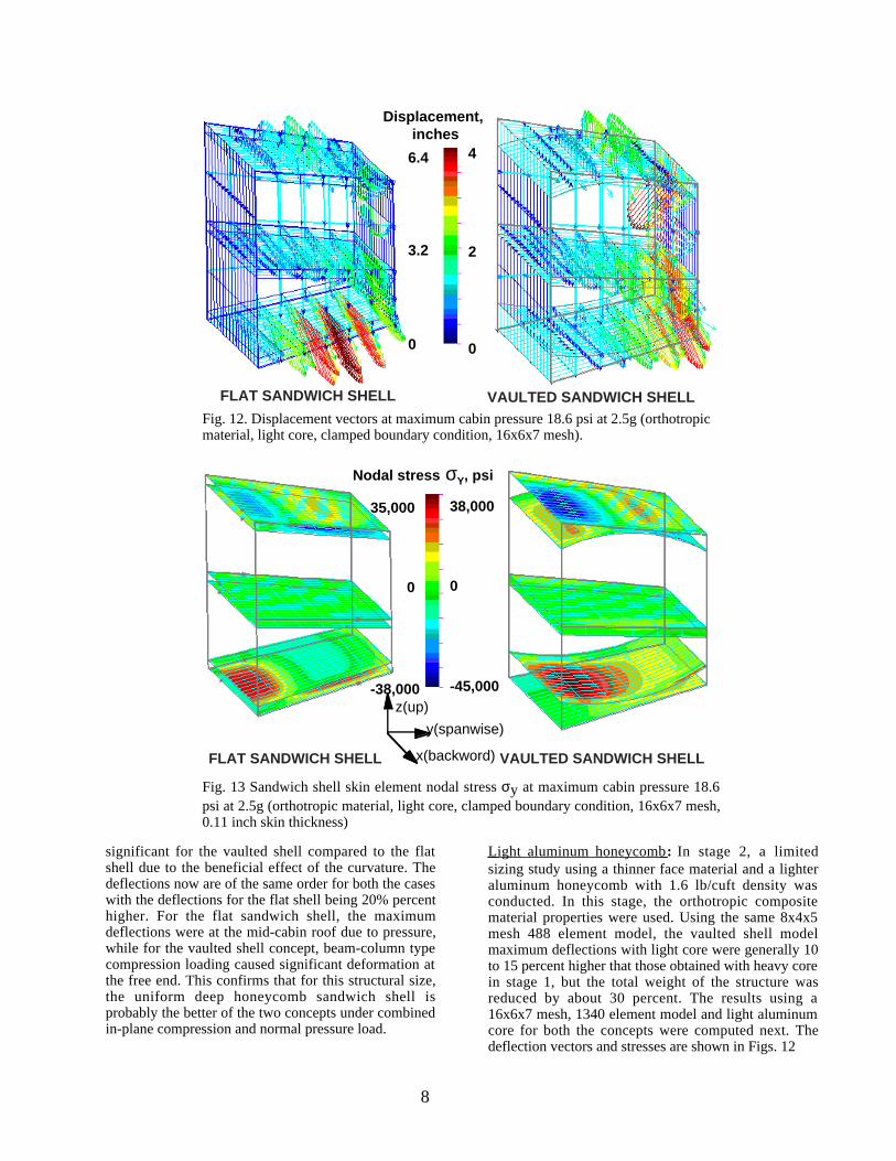
Figure 20 shows the side view ofdeformed shape and rear spar stresses on the top figure.The bottom figure shows the corresponding situationwhen the inner skin of the pressurized fuselage sectionhas a pressure leak, and the internal 18.6 psi pressure isapplied to the outer skin. The lift load is divided equallybetween upper and lower outer skin. The stresses anddeflections at the fuselage region and outer wingbasically remained at the same level. This demonstratedthe fail-safe feature of the vaulted double-skin shellconcept.
Displacement, inches Von Mises Stress, psi185
150
100
50
0
52,000
26,000
250
Fig. 19. Ribbed fuselage-wing displacement and Von-Mises stress distribution at18.6 psi internal pressure and elliptic lift load at 2.5g maneuver condition.
13
7. Concluding remarks
A structural concepts study of non-circular pressurizedfuselage configurations was presented for flying wingapplications. Initial sizing, load, deflection and stressdata were obtained using analytical nonlinear beam-column solution for a simplified configuration of thecabin roof. For a fixed set of geometry andrepresentative critical loading condition, a vaultedsandwich shell concept and a flat sandwich shellconcept were analyzed next using a coarse mesh finiteelement analysis. Since, neither of the concepts offeredany distinctive advantage, the flat shell sandwichconcept was considered to be a better choice due to itssimplicity and fabrication advantage. However, for anymetal-composite honeycomb concept, practical issueslike local crippling, damage tolerance, crackpropagation, splicing, moisture egress, corrosion, cut-out, fabrication and maintenance, also need to beaddressed.
Additional structural systems studies indicated that thestructural weight may be significantly reduced byreplacing the honeycomb core of the sandwich shell byspanwise and chordwise ribs, much like a double skinpressure bulkhead. This double-skin ribbed-shellconcept was analyzed for both the vaulted and flat shellconfigurations and compared with the sandwich
concept results. The results indicatethat a double-skin vaulted ribbed-shell concept could offer significantweight advantage over a flat ribbed-shell concept as well as the both thehoneycomb sandwich concepts withsimilar levels of stresses andd e f l e c t i o n s . H o w e v e r ,manufacturing and fabricationproblems of ribbed double-skin shellstructure need to be resolved forboth conventional and compositeconstruction.
The vaulted double-skin ribbed-shellconcept was also analyzed for anintegrated wing-fuselage finiteelement model. This conceptappeared to be most promising andwas demonstrated to have anadditional fail-safe feature in case ofan inner skin pressure leak. In such asituation this configuration operatesmuch like a suspension bridge totransfer transverse pressure load intotension. The fuselage region wherethe pressurized section ends andouter wing begins and the outerwing region between the wing kinks
were considered to be critically loaded areas whichwould need detailed analysis and design. From thestress distribution pattern, it was apparent that anonlinear buckling analysis as well as an optimizedfully stress design would be necessary for resizing inorder to achieve additional weight advantage.
8. References
1. Niu, M. C. Y., "Airframe Structural Design,"Conmilit Press Ltd., Hong Kong, 1993, pp. 376-428.
2. COSMOS/M Basic FEA System User's Guide,Structural research and Analysis Corporation, SantaMonica, CA, 1993.
3. Timoshenko, S. P. and Gere, J. M., "Theory ofElastic Stability , " McGraw Hill Book Co., New York,1961, pp. 1-11
55000
27500
500
52000
26000
250
Von Mises stress, psi
Von Mises stress, psib) 18.6 psi internal pressure on outer flat skin with aero loads at 2.5 g
a) 18.6 psi internal pressure on inner vaulted skin with aero loads at 2.5 g
Fig. 20. Deformation and Von-Mises stress distribution with 18.6 psi internalpressure applied to, a) inner skin, and b) outer skin of the vaulted ribbed shell tosimulate leak in the pressurized fuselage section (elliptic lift load at 2.5gmaneuver).
![leg.wa.govleg.wa.gov/CodeReviser/WACArchive/Documents/2012/WAC-296-826... · (2/17/09) [Ch. 296-826 WAC—p. 1] Chapter 296-826 Chapter 296-826 WAC ANHYDROUS AMMONIA WAC 296-826-100](https://img.pdfslide.us/doc/110x75/5b2b78217f8b9ae6278b475f/legwa-21709-ch-296-826-wacp-1-chapter-296-826-chapter-296-826-wac.jpg)
![WAC 415 - 02 CHAPTER - Washingtonleg.wa.gov/CodeReviser/WACArchive/Documents/2015/WAC 415 - 02... · (2/27/14) [Ch. 415-02 WAC p. 1] Chapter 415-02 Chapter 415-02 WAC GENERAL PROVISIONS](https://img.pdfslide.us/doc/110x75/5ad016617f8b9aca598d40d7/wac-415-02-chapter-415-0222714-ch-415-02-wac-p-1-chapter-415-02.jpg)

![Chapter 296-52 WAC - leg.wa.govleg.wa.gov/CodeReviser/WACArchive/Documents/2018/WAC 296 - 52 CHAPTER.… · (8/1/17) [ch. 296-52 wac p. 1] chapter 296-52 chapter 296-52 wac safety](https://img.pdfslide.us/doc/110x75/5e1c55c238ed802015030b5e/chapter-296-52-wac-legwa-296-52-chapter-8117-ch-296-52-wac-p-1.jpg)
![WAC 296 - 46B CHAPTERlawfilesext.leg.wa.gov/law/WACArchive/2014/WAC 296... · (11/5/13) [ch. 296-46b wac p. 1] chapter 296-46b chapter 296-46b wac electrical safety standards, administration,](https://img.pdfslide.us/doc/110x75/5f937088d75d77697316c60c/wac-296-46b-296-11513-ch-296-46b-wac-p-1-chapter-296-46b-chapter.jpg)
![WAC 182 - 12 CHAPTER - lawfilesext.leg.wa.govlawfilesext.leg.wa.gov/law/WACArchive/2014/WAC 182 - 12 CHAPTE… · (10/28/13) [Ch. 182-12 WAC p. 1] Chapter 182-12 Chapter 182-12 WAC](https://img.pdfslide.us/doc/110x75/5f937086d75d77697316c603/wac-182-12-chapter-182-12-chapte-102813-ch-182-12-wac-p-1-chapter.jpg)