Embed Size (px)
Citation preview

Presented at the 16th Symposium on Industrial Application of Gas Turbines (IAGT) Banff, Alberta, Canada - October 12-14, 2005
The IAGT Committee is sponsored by the Canadian Gas Association. The IAGT Committee shall not be responsible for statements or opinions advanced in technical papers or in Symposium or meeting discussions
Paper No: 05-IAGT-1.2
INDUSTRIAL APPLICATION OF GAS TURBINES COMMITTEE
New High Efficiency Simple Cycle Gas Turbine -GE’s LMS100����
by
Michael J. Reale GE Energy, Cincinnati, Ohio
James K. Prochaska
GE Energy, Houston, TX

GE Energy (09/05)
GE Energy
New High Efficiency Simple Cycle Gas Turbine – GE’s LMS100™ Authored by:
Michael J. Reale
GE Energy, Cincinnati, Ohio
James K. Prochaska
GE Energy, Houston, TX

GE Energy (09/05)
Biography
Jim Prochaska is Manager of Evaluations, Analysis & Pricing for GE Energy in their aeroderivative
packaging business located in Houston, TX. His organization assists potential customers in their
project development activities using a variety of technical, thermal cycle and economic analysis
models.
GE Energy’s facility in Houston builds and services GE gas turbine generator units in the 5 to 50 MW
range. Prime movers utilized are the GE5, GE10, LM2000, LM2500, LM2500+, LM6000 and LMS100
engines manufactured in Evendale, Ohio and Florence, Italy. The complete packages are built and
tested in Houston.
Jim joined GE Energy (Stewart & Stevenson at the time) in 1985, working in Account and Sales
Manager positions. Previously, he was with GE's Power Systems group since 1973, working in sales
and application engineering for power generation products.
Jim received a Bachelor's Degree in Mechanical Engineering from University of Houston in 1973,
and an MS, Electric Power from Union College in 1975. He holds a US Patent and is a registered
professional engineer in the State of Texas.
Jim and his wife, Vivian, live in Houston and have three daughters and two grandchildren.

New High Efficiency Simple Cycle Gas Turbine – GE’s LMS100™
Contents:
Abstract................................................................................................................................................1
Introduction........................................................................................................................................1
Gas Turbine Design..........................................................................................................................3
Intercooler System Design..........................................................................................................4
Package Design................................................................................................................................5
Reliability and Maintainability ...................................................................................................6
Configurations ..................................................................................................................................6
Performance ......................................................................................................................................7
Simple Cycle.................................................................................................................................... 10
Combined Heat and Power...................................................................................................... 12
Combined Cycle ............................................................................................................................ 12
Core Test ........................................................................................................................................... 12
Full Load Test .................................................................................................................................. 13
Schedule ........................................................................................................................................... 14
Summary.......................................................................................................................................... 14
References ....................................................................................................................................... 16

New High Efficiency Simple Cycle Gas Turbine – GE’s LMS100™
GE Energy (09/05) 1
Abstract
GE has introduced the first modern production gas turbine in the power generation industry to employ off-engine intercooling technology with the use of an external heat exchanger, the LMS100™. This gas turbine provides the highest simple cycle efficiency in the Industry today and comes on the heels of GE’s introduction of the highest combined cycle gas turbine system, the MS9001H. The LMS100™ system combines frame and aeroderivative gas turbine technology for gas fired power generation. This marriage provides customers with cyclic capability without maintenance impact, high simple cycle efficiency, fast starts, high availability and reliability, at low installed cost. The unique feature of this system is the use of intercooling within the compression section of the gas turbine, leveraging technology that has been used extensively in the gas and air compressor industry. Application of this technology to gas turbines has been evaluated by GE and others extensively over many years although it has never been commercialized for large power generation applications. In the past five years, GE has successfully used the SPRINT® patented spray intercooling, evaporative cooling technology between the low and high pressure compressors of the LM6000™ gas turbine. GE’s development of high pressure ratio aircraft gas turbines, like the GE90®, has provided the needed technology to take intercooling to production. The LMS100™ gas turbine intercooling technology provides outputs above 100MW, reaching simple cycle thermal efficiencies in excess of 46%. This represents a 10% increase over GE’s most efficient simple cycle gas turbine available today, the LM6000™.
Introduction
GE chose the intercooled cycle to meet customers’ need for high simple cycle efficiency. The approach to developing an intercooled gas turbine is the result of years of intercooled cycle evaluation along with knowledge developed with operation of SPRINT technology. Matching current technology with customer requirements results in a system approach to achieving a significant improvement in simple cycle efficiency.
The development program requirement was to use existing and proven technology from both GE Transportation (formerly GE Aircraft Engines) and GE Energy (formerly GE Power Systems), and combine them into a system that provides superior simple cycle performance at competitive installed cost. All component designs and materials, including the intercooler system, have been successfully operated in similar or more severe applications. The combination of these components and systems for a production gas turbine is new in the power generation industry.
The GE Transportation CF6-80C2/80E gas turbine provided the best platform from which to develop this new product. With over 100 million hours of operating experience in both aircraft engines and industrial applications, through the LM6000™ gas turbine, the CF6® gas turbine fits the targeted size class. The intercooling process allowed for a significant increase in mass flow compared to the current LM™ product capability. Therefore, GE Energy frame units were investigated for potential Low Pressure Compressors (LPC) due to their higher mass flow designs. The MS6001FA (6FA) gas turbine compressor operates at 460 lbm/sec (209 kg/sec) and provides the best match with the CF6-80C2 High Pressure Compressor (HPC) to meet the cycle needs.

New High Efficiency Simple Cycle Gas Turbine – GE’s LMS100™
GE Energy (09/05) 2
The LMS100™ system includes a 3-spool gas turbine that uses an intercooler between the LPC and the HPC as shown in Fig. 1.
Fig. 1. LMS100™ GT Configuration
Intercooling provides significant benefits to the Brayton cycle by reducing the work of compression for the HPC, which allows for higher pressure ratios, thus increasing overall efficiency. The cycle pressure ratio is 42:1. The reduced inlet temperature for the HPC allows increased mass flow resulting in higher specific power. The lower resultant compressor discharge temperature provides colder cooling air to the turbines, which in turn allows increased firing temperatures at metal temperatures
equivalent to the LM6000™ gas turbine producing increased efficiency. The LMS100™ system is a 2550°F (1380°C) firing temperature class design.
This product is particularly attractive for the peaking and mid-range dispatch applications where cyclic operation is required and efficiency becomes more important with increasing dispatch. With an aeroderivative core the LMS100™ system will operate in cyclic duty without maintenance impact. The high efficiency also provides unique capability for cogeneration applications due to the very high power-to-thermal energy ratio. Simple cycle baseload applications will benefit from the high efficiency, high availability, maintainability and low first cost.
GE is creating a product that changes the game in power generation.
Hot end drive Shaft to Generator
To Intercooler
From Intercooler
Low Pressure Compressor (LPC) First 6 stages of MS6001FA
LPC exit diffuser scroll case
HPC inlet collector scroll case
High Pressure Compressor (HPC)
Standard Annular Combustor (SAC)
2 Stage High Pressure Turbine (HPT)
2 Stage Intermediate Pressure Turbine (IPT)
5 Stage Power Turbine (PT)
Exhaust diffuser
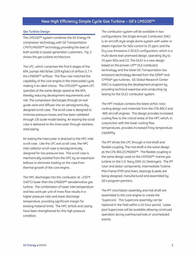
Fig. 2. LMS100TM Gas Turbine
New High Efficiency Simple Cycle Gas Turbine – GE’s LMS100™
GE Energy (09/05) 3
Gas Turbine Design
The LMS100™ system combines the GE Energy FA compressor technology with GE Transportation CF6®/LM6000™ technology providing the best of both worlds to power generation customers. Fig. 2 shows the gas turbine architecture.
The LPC, which comprises the first 6 stages of the 6FA, pumps 460 lb/sec (209 kg/sec) of airflow (1.7 X the LM6000™ airflow). This flow rate matched the capability of the core engine in the intercooled cycle, making it an ideal choice. The LMS100™ system LPC operates at the same design speed as the 6FA, thereby reducing development requirements and risk. The compressor discharges through an exit guide vane and diffuser into an aerodynamically designed scroll case. The scroll case is designed to minimize pressure losses and has been validated through 1/6 scale model testing. Air leaving the scroll case is delivered to the intercooler through stainless steel piping.
Air exiting the intercooler is directed to the HPC inlet scroll case. Like the LPC exit scroll case, the HPC inlet collector scroll case is aerodynamically designed for low pressure loss. This scroll case is mechanically isolated from the HPC by an expansion bellows to eliminate loading on the case from thermal growth of the core engine.
The HPC discharges into the combustor at ~250°F (140°C) lower than the LM6000™ aeroderivative gas turbine. The combination of lower inlet temperature and less work per unit of mass flow results in a higher pressure ratio and lower discharge temperature, providing significant margin for existing material limits. The HPC airfoils and casing have been strengthened for this high pressure condition.
The combustor system will be available in two configurations: the Single Annular Combustor (SAC) is an aircraft style single dome system with water or steam injection for NOx control to 25 ppm; and the Dry Low Emissions-2 (DLE2) configuration, which is a multi-dome lean premixed design, operating dry to 25 ppm NOx and CO. The DLE2 is a new design based on the proven LM™ DLE combustor technology and the latest GE Transportation low emissions technology derived from the GE90® and CFM56® gas turbines. GE Global Research Center (GRC) is supporting the development program by providing technical expertise and conducting rig testing for the DLE2 combustor system.
The HPT module contains the latest airfoil, rotor, cooling design and materials from the CF6-80C2 and -80E aircraft engines. This design provides increased cooling flow to the critical areas of the HPT, which, in conjunction with the lower cooling flow temperatures, provides increased firing temperature capability.
The IPT drives the LPC through a mid-shaft and flexible coupling. The mid-shaft is the same design as the CF6-80C2/LM6000™. The flexible coupling is the same design used on the LM2500™ marine gas turbine on the U.S. Navy DDG-51 Destroyers. The IPT rotor and stator components, Intermediate Turbine Mid-Frame (TMF) and liners, bearings & seals are being designed, manufactured and assembled by GE’s program partners.
The IPT rotor/stator assembly and mid-shaft are assembled to the core engine to create the ‘Supercore.’ This Supercore assembly can be replaced in the field within a 24-hour period. Lease pool Supercores will be available allowing continued operation during overhaul periods or unscheduled events.

New High Efficiency Simple Cycle Gas Turbine – GE’s LMS100™
GE Energy (09/05) 4
GE’s program partners are also designing and manufacturing the Power Turbine (PT) and casing, a 5-stage design based on the LM6000™ and CF6-80C2 designs. The Turbine Rear Frame (TRF) that supports the PT rotor/stator assembly and the Power Turbine Shaft Assembly (PTSA) is based on GE Energy’s frame technology. The PTSA consists of a rotor and hydrodynamic tilt-pad bearings, including a thrust bearing. This system was designed by GE Energy based on extensive frame gas turbine experience. The PT rotor/stator assembly is connected to the PTSA forming a free PT (aerodynamically coupled to the Supercore), which is connected to the generator via a flexible coupling.
The diffuser and exhaust collector combination was a collaborative design effort with the aero design provided by GE Transportation and the mechanical design provided by GE Energy. GE Transportation’s experience with marine modules and GE Energy’s experience with E and F technology diffuser/collector designs were incorporated.
Intercooler System Design
The intercooler system consists of a heat exchanger, piping, bellows expansion joints, moisture separator and variable bleed valve (VBV) system. All process air wetted components are made of stainless steel. The LMS100™ system will be offered with two types of intercooling systems, a wet system that uses an evaporative cooling tower and a dry system (no water required).
The wet system uses an air-to-water heat exchanger of the tube and shell design, as shown in Fig. 3.
Fig. 3. LMS100™ Wet Intercooler System
The tube and shell heat exchanger is used extensively throughout the compressed air and oil & gas industries, among others. The design conditions are well within industry standards of similar-sized heat exchangers with significant industrial operating experience. This design is in general conformance with API 660 and TEMA C requirements.
The intercooler lies horizontal on supports at grade level, making maintenance very easy (see Fig. 4). Applications that have rivers, lakes or the ocean nearby can take advantage of the available cooling water. This design provides plant layout flexibility. In multi-unit sites a series of evaporative cooling towers can be constructed together, away from the GT, if desirable, to optimize the plant design.
An optional configuration using closed loop secondary cooling to a finned tube heat exchanger (replacing the evaporative cooling towers) will also be available. This design uses the same primary heat exchanger (tube and shell), piping, bellows expansion joints and VBV system, providing commonality across product configurations. The secondary cooling system can be water or glycol. This system is beneficial in cold and temperate climates or where water is scarce or expensive.
Cooling tower
Tube & Shell heat exchanger

New High Efficiency Simple Cycle Gas Turbine – GE’s LMS100™
GE Energy (09/05) 5
Fig. 4. LMS100™ Wet Intercooler System with Air-to-Water Heat Exchanger
Package Design
The gas turbine is assembled inside a structural enclosure, which provides protection from the environment while also reducing noise (see Fig. 5). Many customer-sensing sessions were held to determine the package design requirements, which resulted in a design that has easy access for maintenance, quick replacement of the Supercore, high reliability and low installation time. Package design lessons learned from the highly successful LM6000™ gas turbine and GE’s experiences with the 9H installation at Baglan Bay have been incorporated into the LMS100™ system package design. The complete GT driver package can be shipped by truck.
This design significantly reduces installation time and increases reliability.
The auxiliary systems are mounted on a single skid in front of the GT driver package. This skid is pre-assembled and factory tested prior to shipment. The auxiliary skid connects with the base plate through short, flexible connectors. This design improves reliability and reduces interconnects and site installation cost (see Fig. 6).
Fig. 6. LMS100™ System Auxiliary Skid Location
The control system design is a collaboration of GE Transportation and GE Energy. It employs triple processors that can be replaced on-line with redundant instrumentations and sensors. The use of GE Transportation’s synthetic modeling will provide a third level of redundancy based on the successful Full Authority Digital Electronic Control (FADEC) design used in flight engines. The control system is GE Energy’s new Mark VI, which was first successfully proven earlier on the LM6000™ gas turbine in late 2004.
The inlet system is the MS6001FA design with minor modifications to adjust for the elimination of the front-mounted generator and ventilation requirements.
Inlet collector
Exhaust collector
To intercooler
From intercooler
LPC
Supercore engine
PT Drive shaft
Auxiliary Skid
GT Driver package
Fig. 5. LMS100™ System GT Driver

New High Efficiency Simple Cycle Gas Turbine – GE’s LMS100™
GE Energy (09/05) 6
The exhaust systems and intercooler systems are designed for right- or left-handed installation.
Reliability and Maintainability
The LMS100™ system is designed for high reliability and leverages LM™ and GE Energy frame technology and experience, along with GE Transportation technology. The use of Six Sigma processes and methods, and Failure Modes and Effects Analysis (FMEA) for all systems identified areas requiring redundancy or technology improvements.
The control system employs remote I/O (Input/Output) with the use of fiber optics for signal transmission between the package and control system. These connections are typically installed during site construction and have in the past been the source of many shutdowns due to Electro Magnetic Interference (EMI). The LMS100™ design reduces the number of these signal interconnects by 90% and eliminates EMI concerns with the use of fiber optic cables. In addition, the auxiliary skid design and location reduce the mechanical interconnects by 25%, further improving reliability. The use of an integrated system approach based on the latest reliability technology of the GE Transportation flight engine and GE Energy Frame GT is expected to drive the Mean Time Between Forced Outages (MTBFO) of the LMS100™ system up to the best frame gas turbine rate.
The LMS100™ system has the same maintenance philosophy as aeroderivative gas turbines – modular design for field replacement. Design maintenance intervals are the same as the LM6000™ – 25,000 hours hot section repair and 50,000 hours overhaul intervals.
The LPC requires very little maintenance with only periodic borescope inspections at the same time as
the core engine. No other significant maintenance is required.
The Supercore requires combustor, HPT airfoils and IPT airfoils inspection and on-condition repair or replacement at 25,000 hours, which can be accomplished on-site within a 4-day period. The package is designed for 24-hour removal and replacement of the Supercore. Rotable modules for the combustor, HPT and IPT will be used to replace existing hardware. The Supercore and PT rotor/stator module will be returned to the Depot for the 50,000-hour overhaul. During this period a leased Supercore and PT rotor/stator module will be available to continue revenue operation. The LMS100™ core is compatible with existing LM6000™ Depot capabilities.
The PT rotor/stator assembly only requires on-condition maintenance action at 50,000 hours. This module can be removed after the Supercore is removed and replaced with a new module or a leased module during this period.
The PT shaft assembly, like the LPC, needs periodic inspection only.
Configurations
The LMS100™ system is available as a Gas Turbine Generator set (GTG), which includes the complete intercooler system. An LMS100™ Simple Cycle power plant will also be offered. GTG will be offered with several choices of combustor configurations as shown in Table 1.
The GTG is available for 50 and 60 Hz applications and does not require the use of a gearbox.
Wet or dry intercooler systems are available with any of the configurations to best match the site conditions.

New High Efficiency Simple Cycle Gas Turbine – GE’s LMS100™
GE Energy (09/05) 7
Product Offering
Fuel Type
Diluent NOx Level
Power Augmentation
LMS100PA-SAC
(50 or 60 Hz)
Gas or
Dual
Water 25 None
LMS100PA-SAC (50 or 60 Hz)
Gas Steam 25 None
LMS100PA-SAC STIG
(50 or 60 Hz)
Gas Steam 25 Steam
LMS100PB-DLE2 (50 or 60 Hz)
Gas None 25 None
Table 1. LMS100™ System Product Configurations
Optional kits will be made available for cold weather applications and power augmentation for hot ambient when using the dry intercooler system.
All 50 Hz units will meet the requirements of applicable European design and emissions standards.
The generator is available in an air-cooled or TEWAC (totally enclosed, water-to-air cooled) configuration and is dual rated (50 and 60 Hz).
The GTG will be rated for 85-dBA average at 3 feet (1 meter). An option for 80-dBA average at 3 feet (1 meter) will be available after initial field experience.
Performance
The LMS100™ system cycle incorporates an intercooled compressor system. LPC discharge air is cooled prior to entering the HPC. This raises the specific work of the cycle from 150(kW/pps) to 210+(kW/pps). The LMS100™ system represents a significant shift in current power generation gas turbine technology (see Fig. 7 – data from Ref. 1).
Fig. 7. LMS100™ System Specific Work vs. Other Technology
As the specific work increases for a given power the gas turbine can produce this power in a smaller turbine. This increase in technical capability leads to reduced cost. The LMS100™ system changes the game by shifting the technology curve to provide higher efficiency and power in a smaller gas turbine for its class (i.e. relative firing temperature level).
The cycle design was based on matching the existing GE Transportation CF6-80C2 compressor with available GE Energy compressor designs. The firing temperature was increased to the point allowed by the cooled high pressure air to maintain the same maximum metal temperatures as the LM6000™ gas turbine. The result is a design compression ratio of 42:1 and a firing temperature class of 2550°F (1380°C) that produces greater than
E Class
F Class
G ClassLMS100
100
150
200
250
0 100 200 300 400
Power, MW
Spec
ific
Wor
k, K
W/p
psLM6000

New High Efficiency Simple Cycle Gas Turbine – GE’s LMS100™
GE Energy (09/05) 8
46% simple cycle gas turbine shaft efficiency. This represents a 10% increase over GE’s highest efficiency gas turbine available in the Industry today – the LM6000™ gas turbine @ 42% (see Fig. 8 – data from Ref. 1).
Fig. 8. LMS100™ System Competitive Positions
Intercooling provides unique attributes to the cycle. The ability to control the HPC inlet temperature to a desired temperature regardless of ambient temperatures provides operational flexibility and improved performance. The LMS100™ system with the SAC combustion system maintains a high power level up to an ambient temperature of ~80°F (27°C) (see Fig. 9). The lapse rate (rate of power reduction vs. ambient temperature) from 59°F (15°C) to 90°F (32°C) is only 2%, which is significantly less than a typical aeroderivative (~22%) or frame gas turbine (~12%).
The LMS100™ system has been designed for 50 and 60 Hz operations without the need for a speed reduction gearbox. This is achieved by providing a different PT Stage 1 nozzle that is mounted between the Supercore and PT for each speed. The PT design point is optimized to provide the best performance at both 3000 and 3600 rpm operating speeds. Fig. 9 shows that there is a very small difference in performance between the two operating speeds.
Fig. 9. LMS100™ System SAC Performance
Most countries today have increased their focus on environmental impact of new power plants and desire low emissions. Even with the high firing temperatures and pressures, the LMS100™ system is capable of 25ppm NOx at 15% O2 dry. Table 1 shows the emission levels for each configuration. The 25 ppm NOx emissions from an LMS100™ system represent a 30% reduction in pounds of NOx/kWh relative to LM6000™ levels. The high cycle efficiency results in low exhaust temperatures and the ability to use lower temperature SCRs (Selective Catalytic Reduction).
While GT NOx emissions will be controlled using water or steam injection, the levels of CO and UHC emissions are being verified in on-going testing programs. GE has been able to support current customer permitting activity for even the most stringent US regions, such as Southern California, through the planned use of SCR and COR systems in the GT exhaust stream.
Another unique characteristic of the LMS100™ system is the ability to achieve high part-power efficiency. Fig. 10 shows the part-power efficiency versus load. It should be noted that at 50% load the LMS100™ system heat rate (~40% efficiency) is better than most gas turbines at baseload. Also, the
50
70
90
110
0 20 40 60 80 100 120Inlet Temperature, o F
MW
-10 0 10 20 30 40 oC
SAC/Water
DLE
STIG
7EAGT11N2
W501D5A
M701V64.3A
Trent 60
FT8+TP
LM6000PD Sprint
9E
30%
35%
40%
45%
50%
40 80 120 160Genset Output, MW
Gen
set E
ffici
ency
, % SAC/Steam

New High Efficiency Simple Cycle Gas Turbine – GE’s LMS100™
GE Energy (09/05) 9
59°F (15°C) and 90°F (32°C) curves are identical. The LMS100™ system will be available in a STIG (steam injection for power augmentation) configuration providing significant efficiency improvements and power augmentation. Figs. 11 and 12 show the power output at the generator terminals and heat rate, respectively.
Fig. 10. LMS100™ System Part-Power Efficiency
Fig. 11. LMS100™ System STIG Electric Power vs Tambient
Fig. 12. LMS100™ System STIG Heat Rate (LHV)
vs Tambient
The use of STIG can be varied from full STIG to steam injection for NOx reduction only. The later allows steam production for process if needed. Fig. 13 – data from Ref. 1, compares the electrical power and steam production (@ 165 psi/365°F, 11.3 bar/185°C) of different technologies with the LMS100™ system variable STIG performance.
Fig. 13. LMS100™ System Variable STIG for Cogen
The STIG system’s steam-to-process can be varied to match heating or cooling needs for winter or summer, respectively. During the peak season, when
50
70
90
110
130
0 20 40 60 80 100 120Inlet Temperature, ºF
Out
put,
MW
-10 0 10 20 30 40ºC
50 Hz and 60 Hz
LMX SAC Variable STIG
Intercooled Technology Curve
140
120
100
80
60
40
20
0
LMX SACSteam
LMX SACw/Water
LMX DLE
Steam Production, KPPH
Aeroderivative Technology Curve
Frame Technology Curve
Frame 6B
LM6000 PD SPRINT 3
Cogen Technology Fit
Ele
ctric
al O
utpu
t, M
W
0 100 200 300 400 500
Economical Demand Variation Management
35
37
39
41
43
45
47
49
50 60 70 80 90 100% of Baseload
Effic
ienc
y (%
)
50 Hz & 60Hz
40%
6800
7000
7200
7400
0 20 40 60 80 100 120
Hea
t Rat
e, B
TU/K
WH -10 0 10 20 30 40
7200
7800
7500
KJ/
KW
H
50 Hz60 Hz
ºC
Inlet Temperature, ºF

New High Efficiency Simple Cycle Gas Turbine – GE’s LMS100™
GE Energy (09/05) 10
power is needed and electricity prices are high, the steam can be injected into the gas turbine to efficiently produce additional power. During other periods the steam can be used for process. This characteristic provides flexibility to the customer and economic operation under varying conditions.
Fig. 14. LMS100™ System Exhaust Temperatures
Fig. 15. LMS100™ System Exhaust Flow
The LMS100™ system cycle results in low exhaust temperature due to the high efficiency (see Figs. 14 and 15). Good combined cycle efficiency can be achieved with a much smaller steam plant than other gas turbines.
Table 2 shows a summary of the LMS100™ system configurations and their performance. The product flexibility provides the customer with multiple configurations to match their needs while at the same time delivering outstanding performance.
Power(Mwe)
60 HZ
Heat Rate (BTU/KWh)
60 Hz
Power (Mwe)
50 HZ
Heat Rate (KJ/KWh)
50 Hz
DLE 98.7 7509 99.0 7921
SAC w/Water
102.6 7813 102.5 8247
SAC w/Steam
104.5 7167 102.2 7603
STIG 112.2 6845 110.8 7263
Table 2. LMS100™ System Generator Terminal Performance
(ISO 59ºF/15ºC, 60% RH, zero losses, sea level)
Simple Cycle
The LMS100™ system was primarily designed for simple cycle mid-range dispatch. However, due to its high specific work, it has low installed cost, and with no cyclic impact on maintenance cost, it is also competitive in peaking applications. Fig. 16 shows the range of dispatch and power demand over which the LMS100™ system serves as an economical product choice. This evaluation was based on COE analysis at $5.00/MMBTU (HHV).
The LMS100™ will be available in a DLE configuration. This configuration with a dry intercooler system will provide an environmental simple cycle power plant combining high efficiency,
350
400
450
500
0 20 40 60 80 100 120Inlet Temperature, °F
Exha
ust F
low
, lb/
sec
-10 0 10 20 30 40°C
Kg/
Sec
220
19050 Hz and 60 Hz
700
720
740
760
780
800
820
0 20 40 60 80 100 120
Inlet Temperature, ºF
Exha
ust T
empe
ratu
re, º
F
-10 0 10 20 30 40
ºC
390
410
430
50 Hz60 Hz
ºC

New High Efficiency Simple Cycle Gas Turbine – GE’s LMS100™
GE Energy (09/05) 11
low mass emissions rate and without the usage of water.
Fig. 16. LMS100™ System Competitive Regions
In simple cycle applications all frame and aeroderivative gas turbines require tempering fans in the exhaust to bring the exhaust temperature within the SCR material capability. The exhaust temperature (shown in Fig. 14) of the LMS100™ system is low enough to eliminate the requirement for tempering fans and allows use of lower cost SCRs.
Many peaking units are operated in hot ambient conditions to help meet the power demand when air conditioning use is at its maximum. High ambient temperatures usually mean lower power for gas turbines. Customers tend to evaluate gas turbines at 90°F (32°C) for these applications. Typically, inlet chilling is employed on aeroderivatives or evap-orative cooling for heavy duty and aeroderivative engines to reduce the inlet temperature and increase power. This adds fixed cost to the power plant along with the variable cost adder for water usage. The power versus temperature profile for the LMS100™ system in Fig. 9 shows power to be increasing to 80°F (27°C) and shows a lower lapse rate beyond that point versus other gas turbines. This eliminates the need for inlet chilling thereby reducing the product cost and parasitic losses.
Evaporative cooling can be used above this point for additional power gain.
Simple cycle gas turbines, especially aeroderivatives, are typically used to support the grid by providing quick start (10 minutes to full power) and load following capability. The LMS100™ system is the only gas turbine in its size class with both of these capabilities. High part-power efficiency, as shown in Fig. 10, enhances load following by improving LMS100™ system operating economics.
Fig. 17. LMS100™ System Gas Turbine Grid Frequency Variations
Many countries require off-frequency operation without significant power loss in order to support the grid system. The United Kingdom grid code permits no reduction in power for 1% reduction in grid frequency (49.5 Hz) and 5% reduction in power for an additional 5% reduction in grid frequency (47 Hz). Fig. 17 shows the impact of grid frequency variation on 3 different gas turbines: a single shaft, a 2-shaft and the LMS100™ system. Typically, a single and 2-shaft engine will need to derate power in order to meet the UK code requirements.
The LMS100™ system can operate with very little power variation for up to 5% grid frequency variation. This product is uniquely capable of
-20%
-16%
-12%
-8%
-4%
0%
4%
45 47.5 50 52.5 55Grid Frequency
Dev
iatio
n in
GT
Out
put
2 Shaft GT
LMS100DLE
Single Shaft GT
LMS100 SAC/Water
UK Grid Code Requirement
Single
0
2000
4000
6000
8000
Peakers
BaseloadMultiple
50 100 150 200 250 300 350 400Plant Output
Dis
patc
h
*Based on COE studies @ $5.00/ mmbtu
LMS100 Region of Competitive

New High Efficiency Simple Cycle Gas Turbine – GE’s LMS100™
GE Energy (09/05) 12
supporting the grid in times of high demand and load fluctuations.
Combined Heat and Power
Combined Heat and Power (CHP) applications commonly use gas turbines. The exhaust energy is used to make steam for manufacturing processes and absorption chilling for air conditioning, among others. The LMS100™ system provides a unique characteristic for CHP applications. As shown in Fig. 13, the higher power-to-steam ratio can meet the demands served by 40-50MW aeroderivative and frame gas turbines and provide more than twice the power. From the opposite view, at 100MW the LMS100™ system can provide a lower amount of steam without suffering the significant efficiency reduction seen with similar size gas turbines at this steam flow. This characteristic creates opportunities for economical operation in conjunction with lower steam demand.
Fig. 18. LMS100™ System Intercooler Heat Rejections
Fig. 18 shows the intercooler heat dissipation, which ranges from 20-30MW of thermal energy. With an air-to-water intercooler system, the energy can be captured for low-grade steam or other applications, significantly raising the plant efficiency level. Using
exhaust and intercooler energy, an LMS100™ plant will have >85% thermal efficiency.
Combined Cycle
Even though the LMS100™ system was aimed at the mid-range dispatch segment, it is also attractive in the combined cycle segment. Frame gas turbines tend to have high combined cycle efficiency due to their high exhaust temperatures. In the 80-160MW class, combined cycle efficiencies range from 51–54%. The LMS100™ system produces 120MW at 53.8% efficiency in combined cycle.
A combined cycle plant based on a frame type gas turbine produces 60-70% of the total plant power from the gas turbine and 30-40% from the steam turbine. In combined cycle the LMS100™ system produces 85-90% of the total plant power from the gas turbine and 10-15% from the steam turbine. This results in a lower installed cost for the steam plant.
The lower exhaust temperature of the LMS100™ system also allows significantly more power from exhaust system duct firing for peaking applications. Typical frame gas turbines exhaust at 1000°F-1150°F (538°C-621°C) which leaves 300°F-350°F (149°C-177°C) for duct firing. With the LMS100™ exhaust temperatures at <825°F (440°C) and duct-firing capability to 1450°F (788°C) (material limit) an additional 30MW can be produced.
Core Test
The core engine, a gas generator consisting of the LMS100™ high-pressure compressor, single annular combustor and high-pressure turbine, completed testing in December 2004 at the high altitude test cell in GE Transportation’s test facility in Ohio. The testing confirmed aeromechanics, mechanical design and variable geometry optimization for performance, paving the way for full scale power plant validation testing.
50
70
90
110
130
0 20 40 60 80 100 120Inlet Temperature, oF
I/C H
eat D
issi
patio
n,
MM
BTU
/Hr
-10 0 10 20 30 40
oC
MW
ther
mal
15
25
3550 Hz60 Hz

New High Efficiency Simple Cycle Gas Turbine – GE’s LMS100™
GE Energy (09/05) 13
The unit ran for more than 66 hours, during which over 500 transient data and 800 steady state data readings using more than 2500 sensors were taken. The core engine achieved 100% start reliability, with 40 on natural gas and 34 on either Jet A or diesel fuel.
Testing included successful operation during each of the following:
Start fuel schedule optimisation on gas and liquid
Start, off-idle and open VSV stall mapping
Compressor aeromechanics at various IGV and VSV schedules and at varying inlet pressures.
Performance power calibrations
Rotor thrust control characterization
Bore cooling impact upon clearances / stall margins
Heat transfer mapping of rotors and structures
Cool down / bowed rotor restart characterization
Emissions testing on both gas and diesel fuel
Full Load Test
GE Energy has expanded it’s capabilities in Houston to include string testing new LMS100™ gas turbine generator sets. The test facility includes three foundations designed specifically for the LMS100™ -- two test bays to support full speed, partial load testing, and a third to support full load string testing with customer equipment. The facility civil works and mechanical and electrical construction to support the full load test bay and balance of plant equipment were completed in June, 2005.
The full-scale validation-testing phase of the LMS100™ program is now underway at GE Energy's Jacinto Port facility in Houston, Texas, Fig. 19. The initial phase will validate the gas turbine generator design including the intercooling system. More than
3000 pieces of instrumentation is used to measure key design parameters. Planned demonstrations include performance at full load and part power conditions, operability (including 10 minute starts), emissions, and noise.
The gas turbine was first fired on July 18th and has completed 3 fired starts in the first week with a 100% start success rate. All subsystems were verified, including lube oil, hydraulic, intercooler variable bleed valve system, controls operation and all test and production instrumentation. The subsystems main operation, back-up systems and emergency shutdown systems were also tested and validated.
Fig. 19. LMS100™ Full Load Test In Houston
In August, 2005, the unit successfully achieved sync idle operation, verifying combustor start-up operation, low speed booster operability, intercooler variable bleed valve operation and thermal studies at idle conditions. The gas turbine and supporting systems continue to perform as expected. Preliminary evaluations show all rotor and airfoil vibratory responses within expected ranges, with no identified anomalies.

New High Efficiency Simple Cycle Gas Turbine – GE’s LMS100™
GE Energy (09/05) 14
By mid September 2005, the LMS100™ has accumulated over 31 hours of operation with 26 starts at 100% starting reliability and has achieved a load of 94 MW at high ambient temperatures. The gas turbine is meeting or exceeding expectations and will continue testing as planned for the remainder of the year.
After testing is complete, the Supercore and PT rotor/stator assemblies will be replaced with production (uninstrumented) hardware. The complete system will be shipped to the demonstration customer site for endurance testing. This site will be the “Fleet Leader,” providing early evaluation of product reliability.
Schedule
The first production GTG will be available for shipment from GE Energy’s aeroderivative facility in Jacintoport, Texas by the end of this year. Configurations available at this time will be SAC gas fuel, with water injection, or dual fuel with water injection. Both configurations will be available for 50 and 60 Hz applications. Gas furl with steam injection and STIG will be available in mid-2008. The DLE2 combustion system development is scheduled to be complete in early 2008. Therefore, a LMS100™ system configured with DLE2 combustor in 50 or 60 Hz will be available in the second half of 2008.
Summary
The LMS100™ system provides significant benefits to power generation operators as shown in Table 3. The LMS100™ system represents a significant change in power generation technology. Having a significant experience base in both frame and aero technology allows GE to offer unparalleled advances in simple cycle efficiency and power generation flexibility.

New High Efficiency Simple Cycle Gas Turbine – GE’s LMS100™
GE Energy (09/05) 15
High simple cycle efficiency over a wide load range Low lapse rate for sustained hot day power
Low specific emissions (mass/kWh)
50 or 60 Hz capability without a gearbox
Fuel flexibility – multiple combustor configurations
Flexible power augmentation
Designed for cyclic operation:
- No maintenance cost impact
10-minute start to full power
- Improves average efficiency in cyclic applications
- Potential for spinning reserves credit
- Low start-up and shutdown emissions
Load following capability
Synchronous condenser operation
High availability:
- Enabled by modular design
- Rotable modules
- Supercore and PT lease pool
Low maintenance cost
Designed for high reliability
Flexible plant layout
- Left- or right-hand exhaust and/or intercooler installation
Operates economically across a wide range of dispatched hours
Table 3. LMS100™ Customer Benefits

New High Efficiency Simple Cycle Gas Turbine – GE’s LMS100™
GE Energy (09/05) 16
References:
Gas Turbine World (GTW); “2003 GTW Handbook,” Volume 23
LMS100 is a trademark of GE Energy.
GE90, CF6 and LM2500 are registered trademarks of General Electric Company.
LM6000 is a trademark of General Electric Company.
MS6001 is a trademark of GE Energy.
CFM56 is a registered trademark of CFM International, a joint company of Snecma Moteurs, France, and General Electric Company.
SPRINT is a registered trademark of General Electric Company.
© Copyright 2004 General Electric Company. All rights reserved.