Embed Size (px)
Citation preview
Copyright 2009, International Petroleum Technology Conference This paper was prepared for presentation at the International Petroleum Technology Conference held in Doha, Qatar, 7–9 December 2009. This paper was selected for presentation by an IPTC Programme Committee following review of information contained in an abstract submitted by the author(s). Contents of the paper, as presented, have not been reviewed by the International Petroleum Technology Conference and are subject to correction by the author(s). The material, as presented, does not necessarily reflect any position of the International Petroleum Technology Conference, its officers, or members. Papers presented at IPTC are subject to publication review by Sponsor Society Committees of IPTC. Electronic reproduction, distribution, or storage of any part of this paper for commercial purposes without the written consent of the International Petroleum Technology Conference is prohibited. Permission to reproduce in print is restricted to an abstract of not more than 300 words; illustrations may not be copied. The abstract must contain conspicuous acknowledgment of where and by whom the paper was presented. Write Librarian, IPTC, P.O. Box 833836, Richardson, TX 75083-3836, U.S.A., fax +1-972-952-9435.
ABSTRACT Drilling with a bottomhole pressure less than the formation pore pressure (Underbalanced Drilling, UBD) usually increase the risk of borehole instability due to yielding or failure of the rock adjacent to the borehole. But evaluation criterion of this failure mechanism is complex and very often diagnosis did not fit with field operational practices. It is believed that, shear and radial tensile failures with negligible chemical instability are the common mechanisms to cause mechanical instability in UBD in shales. In a mechanical borehole instability perspective, UBD causes lots of potential challenges and formation uncertainities due to facts like:
Insufficient case data related to borehole instability; Complex physics of borehole instability mechanisms ; Requirement to conduct excessive experimental work which is costly and time consuming; Scarcity of real shales specimen and reluctant for coring of shales; Reliability of fitting material constitutive model to analyse shales; Dependable model to predict wellbore collapse pressure; Uncertainty to predict pore pressure and permeability of shale formation; Variable pressure regimes (i.e., shale heterogeneity);
A detailed workflow in connection within physical, experimental, analytical and numerical investigation is required to understand and to diagnose borehole stability. Numerous studies have been carried out so far on borehole stability design, but UBD and shale instability is new research areas where more insight is needed. This paper discuss and presents mechanical borehole instability both analytically and numerically to quantify borehole collapse risk for inclined wells under in- situ stress state. In addition produce comparable results and therefore some physical models are also presented for in depth study of UBD. Results show that the developed analytical and numerical models are enabled to predict borehole collapse risk. Since several real- life situations were evaluated, the potential applicability of the models is apparent; the results could be used as cross checks for particular situations in the field. The generality of this study provided an overview along with standard workflow into borehole collapse assessment which may helps to obtain proper diagnosis of material failure state with respect to reduction of instability in drilling. Findings of this study can be useful for further research within the same area. KEYWORDS: UBD, shales, mechanical instability, collapse pressure, pore pressure, mud weight window.
IPTC 13826
Underbalanced Drilling in Shale - Perspective of Factors Influences Mechanical Borehole Instability *Md. Aminul Islam, Pål Skalle and Evgeniy Tantserev, Department of Petroleum Engineering and Applied Geophysics, NTNU
2 IPTC 13475
1.0 Introduction Underbalanced Drilling (UBD) means the wellbore pressure is intentionally set below the formation pressure. Moreover, during tripping or tool joint operation in Overbalanced Drilling (OBD), borehole annular pressure also goes through underbalanced (UB) situation compare to formation pore pressure. Thus, borehole underbalanced circumstances does not only concern UBD, but also matter for OBD. The consequence of the underbalanced state may lead to borehole instability. UBD technique has become an art in the modern oil industry, often applied to avoid or mitigate formation damage, reduce lost circulation risk, enhanced recovery and increase ROP. However, in recent years, several new challenge have appeared, making the stability issue in shales more difficult to handle, and thus also more important to solve. For operational benefit, there has been an increasing demand by the industry for better understanding of shale behavior in underbalanced drilling. Shale is specifically mentioned in this setting, due to the fact that borehole instability is more pronounced in such formations than any other formation. From field experience, it was found that shale make up more than 75 % of drilled formations, and more than 70 % of borehole problems are caused by shale instability. In addition, many fields are in a depleting trend, infill drilling would be a big challenge; the same is true for drilling in tectonically active areas, in deep sea, and in deep and geologically complex surroundings. In practice, infill drilling operation requires UBD to penetrate heterogeneous formation pressured zone. For several reasons, UBD can be a good tool in near futures. However; a reliability borehole stability material models is needed, one that can solve the following possible uncertainities:
Geo-pressured shale which is unstable and tends to slough into the wellbore when the high pore pressure is alleviated by the lower wellbore pressure;
Hole collapse or wellbore caving due to insufficient “support” by the wellbore pressure;
All this uncertainities is a result of mechanical borehole instability, it can result in hole enlargements or hole collapse which causes fill on trips, poor directional control, poor cementing, repeated reaming, or, in extreme conditions, stuck drill pipe.
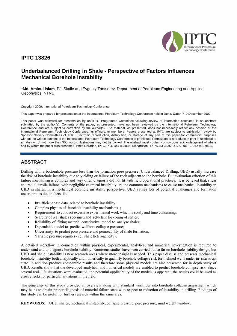
It is assumed that during UBD in shale, due to lack of mud support immediate shear failure may occur depending on type of shale formation and its rock strength. However, if the borehole would overcome the initial failure risk, instability risk may be reduced by equilibrating pore pressure [Chenevert et al 2002, Fjær et al, 2008]. But due to the extremely low permeability of shales, the pore fluid cannot flow freely, which causes redistribution of stresses and possibility wellbore instability [Chen and Ewy, 2002]. So, knowledge of collapse pressure model in addition to pore pressure behaviour in shales is considered the most crucial factors for wellbore design in UBD. Fig.1, presents the hypothesis of near wellbore stress pattern for UBD candidates. The critical region is located (blue shaded area) where shear and radial tensile failure are the resultant mechanisms. Shear failure of the borehole wall will take place when the stress concentration around the borehole exceeds the compressive strength of the rock [Fjær et al., 2008]. The strategy should therefore be to set the lowest mud weight possible in shale without collapse and simultaneously attempt to manage the losses in sand when drilling in interbedded formations. UBD is a relatively new technology, but its potential has yet to be fully realized by the industry. Particularly has borehole stability not been well addressed, as confirmed from a literature survey? It was found that most of the studies (Mody and Hale 1993, Van Oort 1997, Fonseca 2000, Anthony et al. 2002, Nobuo morita 2004) discussed perational challenges with potential benefits. Various field trials studied by Davison (2004) in the Brent field, reported that 700-900 psi is the maximum underbalance pressure for sub horizontal wells in shale which maintain a low risk of failure. This result can be used as reference, however, will be required a separate and more in-depth study of the zones where UBD is planned. As it is discussed, borehole collapse risk is the potential challange for UBD; hence for investigation of borehole instability, a suitable material model is essential to evaluate borehole collapse risk. Up until now, borehole collapse material model is apply on elastic – elastoplastic material model [Fairhurst et al. 1968, Bradely et al. 1987, Adanøy et al. 1987, 2002 & 2004, Al-Ajmi et al. 2006, Fjær et al. 2008]. It is observed that in- situ stress assessment and it used as input is the most exemplified weak
Fig.1 Borehole stresses in UBD condition
IPTC 13475 3
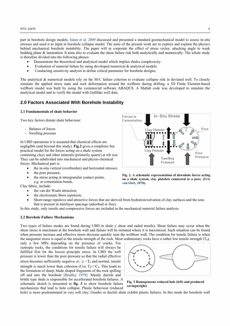
Fig. 3 Homogeneous reduced hole (left) and produced cavings(right)
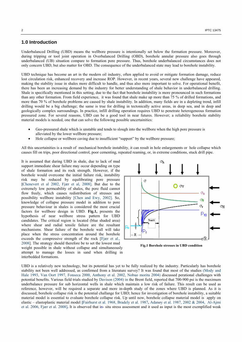
Fig. 2. A schematic representation of downhole forces acting on a shale system, clay platelets connected to a pore. (Eric van Oort, 1878).
part in borehole design models. Islam et al. 2009 discussed and presented a standard geomechanical model to assess in-situ stresses and used it as input in borehole collapse model. The aims of the present work are to explore and explain the physics behind mechanical borehole instability. The paper will in corporate the effect of stress vector, attacking angle to weak bedding plane & lamination. It aims also to evaluate the shear failure risk both analytically and numerically. The whole study is therefore divided into the following phases:
Demonstrate the theoretical and analytical model which implies shales complexicity. Evaluation of material failure by using developed numerical & analytical models. Conducting sensitivity analysis to define critical parameter for borehole designs;
The analytical & numerical models rely on the M-C failure criterion to evaluate collapse risk in deviated well. To closely simulate the applied stress state and rock deformation around the wellbore during drilling, a 3D Finite Element-based wellbore model was built by using the commercial software ABAQUS. A Matlab code was developed to simulate the analytical model and to verify the model with Gullfaks well data. 2.0 Factors Associated With Borehole Instability 2.1 Fundamentals of shale behavior Two key factors distate shale behaviour: - Balance of forces - Swelling pressure In UBD operations it is assumed that chemical effects are negligible (and beyond this study). Fig.2 gives a simplistic but practical model for the forces acting on a shale system containing clays and other minerals (primarily quartz) at silt size. They can be subdivided into mechanical and physio-chemical forces. Mechanical part is:
the in-situ vertical (overburden) and horizontal stresses; the pore pressure; the stress acting at intergranular contact points,
e.g. at cementation bonds. Clay fabric, include:
the van der Waals attraction; the electrostatic Born repulsion; Short-range repulsive and attractive forces that are derived from hydration/solvation of clay surfaces and the ions
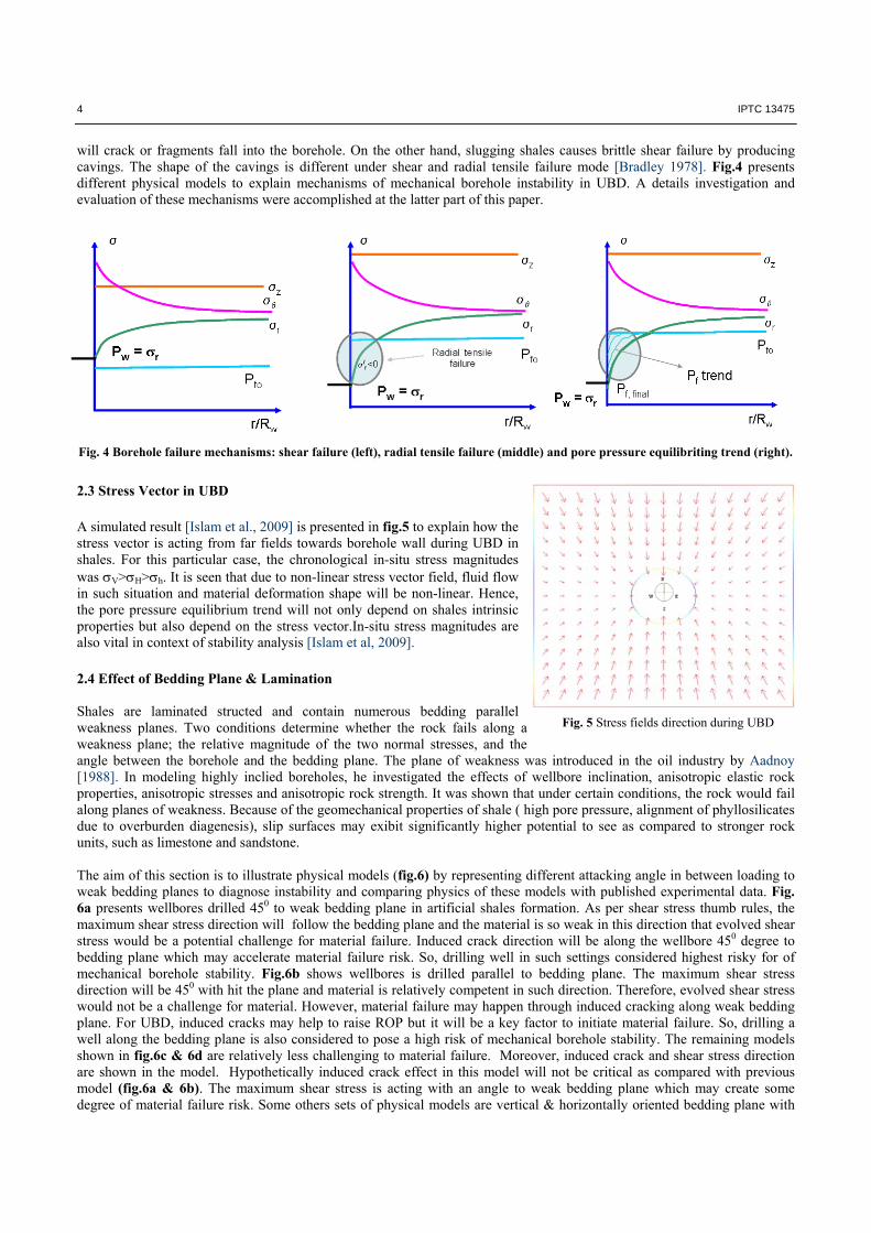
that is present in interlayer spacings (adsorbed or free). In this study, only tensile and compressive forces are included in the mechanical material failure analysis. 2.2 Borehole Failure Mechanisms Two types of failure modes are found during UBD in shale ;( shear and radial tensile). Shear failure may occur when the shear stress is maximum at the borehole wall and failure will be initiated where it is maximized. Such situation can be found when pressure increase and effective stress decrease quickly near the wellbore wall. The condition for tensile failure is when the tangential stress is equal to the tensile strength of the rock. Most sedimentary rocks have a rather low tensile strength (T0), only a few MPa depending on the presence of cracks. For isotropic rocks, the conditions for tensile failure will always be fulfilled first for the lowest principle stress. In UBD the well pressure is lower than the pore pressure so that the radial effective stress becomes sufficiently negative 0
/ r and normal, tensile strength is much lower than cohesion (Co), T0<<C0. This leads to the formation of sharp, blade shaped fragments of the rock spilling off and into the borehole [Bradley 1978]. Mainly ductile and brittle type shale is responsible for accellerated borehole failures. A schematic sketch is presented in fig. 3 to show borehole failure mechanisms that lead to hole collapse. Plastic behaviour (reduced hole) is more predominated in very soft clay; Gumbo or ductile shale exhibit plastic failures. In this mode the borehole wall
4 IPTC 13475
will crack or fragments fall into the borehole. On the other hand, slugging shales causes brittle shear failure by producing cavings. The shape of the cavings is different under shear and radial tensile failure mode [Bradley 1978]. Fig.4 presents different physical models to explain mechanisms of mechanical borehole instability in UBD. A details investigation and evaluation of these mechanisms were accomplished at the latter part of this paper.
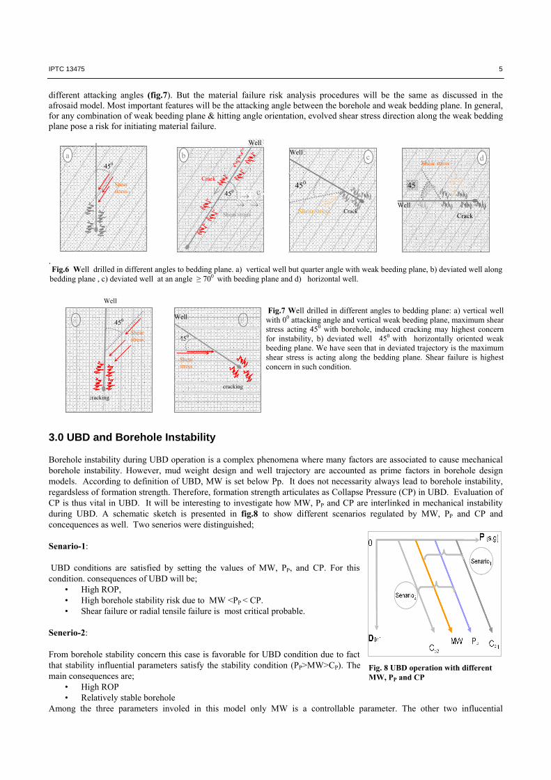
2.3 Stress Vector in UBD A simulated result [Islam et al., 2009] is presented in fig.5 to explain how the stress vector is acting from far fields towards borehole wall during UBD in shales. For this particular case, the chronological in-situ stress magnitudes was V>H>h. It is seen that due to non-linear stress vector field, fluid flow in such situation and material deformation shape will be non-linear. Hence, the pore pressure equilibrium trend will not only depend on shales intrinsic properties but also depend on the stress vector.In-situ stress magnitudes are also vital in context of stability analysis [Islam et al, 2009]. 2.4 Effect of Bedding Plane & Lamination Shales are laminated structed and contain numerous bedding parallel weakness planes. Two conditions determine whether the rock fails along a weakness plane; the relative magnitude of the two normal stresses, and the angle between the borehole and the bedding plane. The plane of weakness was introduced in the oil industry by Aadnoy [1988]. In modeling highly inclied boreholes, he investigated the effects of wellbore inclination, anisotropic elastic rock properties, anisotropic stresses and anisotropic rock strength. It was shown that under certain conditions, the rock would fail along planes of weakness. Because of the geomechanical properties of shale ( high pore pressure, alignment of phyllosilicates due to overburden diagenesis), slip surfaces may exibit significantly higher potential to see as compared to stronger rock units, such as limestone and sandstone. The aim of this section is to illustrate physical models (fig.6) by representing different attacking angle in between loading to weak bedding planes to diagnose instability and comparing physics of these models with published experimental data. Fig. 6a presents wellbores drilled 450 to weak bedding plane in artificial shales formation. As per shear stress thumb rules, the maximum shear stress direction will follow the bedding plane and the material is so weak in this direction that evolved shear stress would be a potential challenge for material failure. Induced crack direction will be along the wellbore 450 degree to bedding plane which may accelerate material failure risk. So, drilling well in such settings considered highest risky for of mechanical borehole stability. Fig.6b shows wellbores is drilled parallel to bedding plane. The maximum shear stress direction will be 450 with hit the plane and material is relatively competent in such direction. Therefore, evolved shear stress would not be a challenge for material. However, material failure may happen through induced cracking along weak bedding plane. For UBD, induced cracks may help to raise ROP but it will be a key factor to initiate material failure. So, drilling a well along the bedding plane is also considered to pose a high risk of mechanical borehole stability. The remaining models shown in fig.6c & 6d are relatively less challenging to material failure. Moreover, induced crack and shear stress direction are shown in the model. Hypothetically induced crack effect in this model will not be critical as compared with previous model (fig.6a & 6b). The maximum shear stress is acting with an angle to weak bedding plane which may create some degree of material failure risk. Some others sets of physical models are vertical & horizontally oriented bedding plane with
Fig. 5 Stress fields direction during UBD
Fig. 4 Borehole failure mechanisms: shear failure (left), radial tensile failure (middle) and pore pressure equilibriting trend (right).
IPTC 13475 5
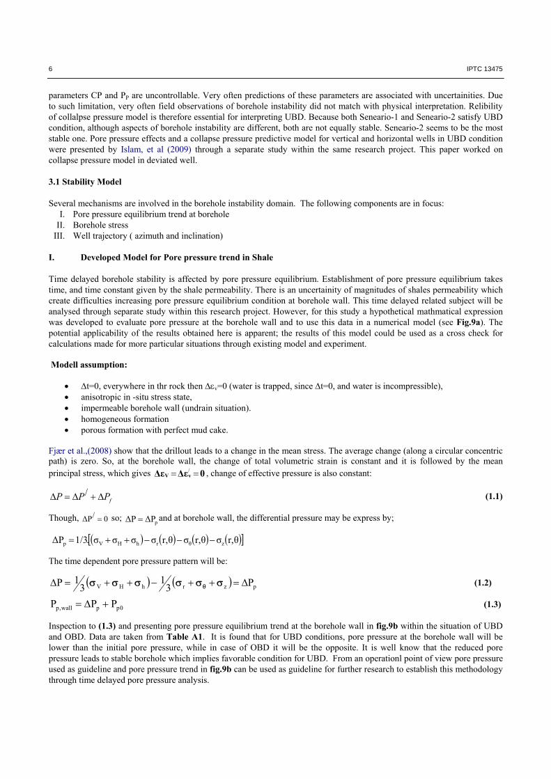
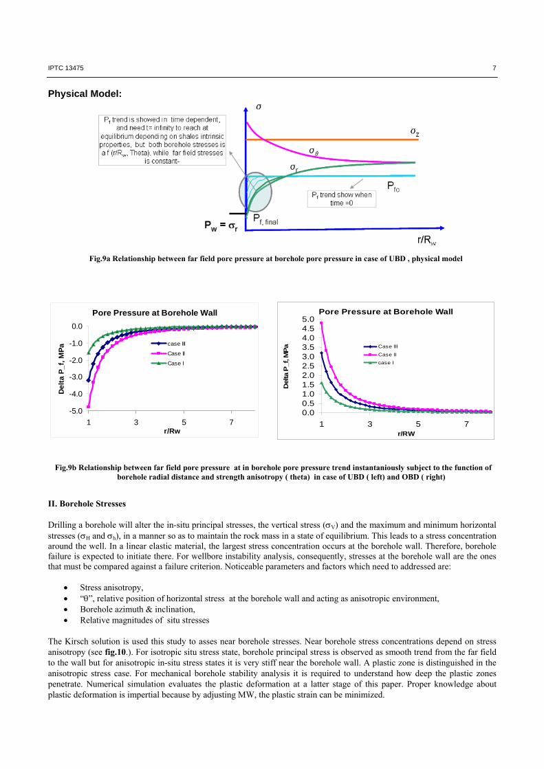
different attacking angles (fig.7). But the material failure risk analysis procedures will be the same as discussed in the afrosaid model. Most important features will be the attacking angle between the borehole and weak bedding plane. In general, for any combination of weak beeding plane & hitting angle orientation, evolved shear stress direction along the weak bedding plane pose a risk for initiating material failure. . 3.0 UBD and Borehole Instability Borehole instability during UBD operation is a complex phenomena where many factors are associated to cause mechanical borehole instability. However, mud weight design and well trajectory are accounted as prime factors in borehole design models. According to definition of UBD, MW is set below Pp. It does not necessarity always lead to borehole instability, regardsless of formation strength. Therefore, formation strength articulates as Collapse Pressure (CP) in UBD. Evaluation of CP is thus vital in UBD. It will be interesting to investigate how MW, PP and CP are interlinked in mechanical instability during UBD. A schematic sketch is presented in fig.8 to show different scenarios regulated by MW, PP and CP and concequences as well. Two senerios were distinguished; Senario-1: UBD conditions are satisfied by setting the values of MW, PP, and CP. For this condition. consequences of UBD will be;
• High ROP, • High borehole stability risk due to MW <PP < CP. • Shear failure or radial tensile failure is most critical probable.
Senerio-2: From borehole stability concern this case is favorable for UBD condition due to fact that stability influential parameters satisfy the stability condition (PP>MW>CP). The main consequences are;
• High ROP • Relatively stable borehole
Among the three parameters involed in this model only MW is a controllable parameter. The other two influcential
Fig.6 Well drilled in different angles to bedding plane. a) vertical well but quarter angle with weak beeding plane, b) deviated well along bedding plane , c) deviated well at an angle ≥ 700 with beeding plane and d) horizontal well.
Shear stress
Well
450
Crack
cShear stress
Well
45
Crack
d
Shear stress
Well
450
c
Crack
b
450
Shear stress
a
Fig.7 Well drilled in different angles to bedding plane: a) vertical well with 00 attacking angle and vertical weak beeding plane, maximum shear stress acting 450 with borehole, induced cracking may highest concern for instability, b) deviated well 450 with horizontally oriented weakbeeding plane. We have seen that in deviated trajectory is the maximum shear stress is acting along the bedding plane. Shear failure is highestconcern in such condition.
Well
450
Shear stress
cracking
450
Shear stress
cracking
Well a b
Fig. 8 UBD operation with different MW, PP and CP
6 IPTC 13475
parameters CP and PP are uncontrollable. Very often predictions of these parameters are associated with uncertainities. Due to such limitation, very often field observations of borehole instability did not match with physical interpretation. Relibility of collalpse pressure model is therefore essential for interpreting UBD. Because both Seneario-1 and Seneario-2 satisfy UBD condition, although aspects of borehole instability are different, both are not equally stable. Seneario-2 seems to be the most stable one. Pore pressure effects and a collapse pressure predictive model for vertical and horizontal wells in UBD condition were presented by Islam, et al (2009) through a separate study within the same research project. This paper worked on collapse pressure model in deviated well. 3.1 Stability Model Several mechanisms are involved in the borehole instability domain. The following components are in focus:
I. Pore pressure equilibrium trend at borehole II. Borehole stress
III. Well trajectory ( azimuth and inclination) I. Developed Model for Pore pressure trend in Shale Time delayed borehole stability is affected by pore pressure equilibrium. Establishment of pore pressure equilibrium takes time, and time constant given by the shale permeability. There is an uncertainity of magnitudes of shales permeability which create difficulties increasing pore pressure equilibrium condition at borehole wall. This time delayed related subject will be analysed through separate study within this research project. However, for this study a hypothetical mathmatical expression was developed to evaluate pore pressure at the borehole wall and to use this data in a numerical model (see Fig.9a). The potential applicability of the results obtained here is apparent; the results of this model could be used as a cross check for calculations made for more particular situations through existing model and experiment. Modell assumption:
t=0, everywhere in thr rock then v=0 (water is trapped, since t=0, and water is incompressible), anisotropic in -situ stress state, impermeable borehole wall (undrain situation). homogeneous formation porous formation with perfect mud cake.
Fjær et al.,(2008) show that the drillout leads to a change in the mean stress. The average change (along a circular concentric path) is zero. So, at the borehole wall, the change of total volumetric strain is constant and it is followed by the mean principal stress, which gives 0ΔεΔε vV / , change of effective pressure is also constant:
/fP P P (1.1)
Though, 0/ΔP so;
pΔPΔP and at borehole wall, the differential pressure may be express by; θr,σθr,σθr,σσσσ.1/3ΔΡ zθrhHVp The time dependent pore pressure pattern will be:
pzrhHV 31
31P (1.2)
0ppwall,p PPP (1.3) Inspection to (1.3) and presenting pore pressure equilibrium trend at the borehole wall in fig.9b within the situation of UBD and OBD. Data are taken from Table A1. It is found that for UBD conditions, pore pressure at the borehole wall will be lower than the initial pore pressure, while in case of OBD it will be the opposite. It is well know that the reduced pore pressure leads to stable borehole which implies favorable condition for UBD. From an operationl point of view pore pressure used as guideline and pore pressure trend in fig.9b can be used as guideline for further research to establish this methodology through time delayed pore pressure analysis.
IPTC 13475 7
Physical Model:
Pore Pressure at Borehole Wall
-5.0
-4.0
-3.0
-2.0
-1.0
0.0
1 3 5 7r/Rw
De
lta
P_
f, M
Pa case III
Case II
Case I
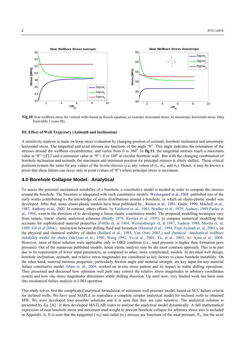
II. Borehole Stresses Drilling a borehole will alter the in-situ principal stresses, the vertical stress (V) and the maximum and minimum horizontal stresses (H and h), in a manner so as to maintain the rock mass in a state of equilibrium. This leads to a stress concentration around the well. In a linear elastic material, the largest stress concentration occurs at the borehole wall. Therefore, borehole failure is expected to initiate there. For wellbore instability analysis, consequently, stresses at the borehole wall are the ones that must be compared against a failure criterion. Noticeable parameters and factors which need to addressed are:
Stress anisotropy, “”, relative position of horizontal stress at the borehole wall and acting as anisotropic environment, Borehole azimuth & inclination, Relative magnitudes of situ stresses
The Kirsch solution is used this study to asses near borehole stresses. Near borehole stress concentrations depend on stress anisotropy (see fig.10.). For isotropic situ stress state, borehole principal stress is observed as smooth trend from the far field to the wall but for anisotropic in-situ stress states it is very stiff near the borehole wall. A plastic zone is distinguished in the anisotropic stress case. For mechanical borehole stability analysis it is required to understand how deep the plastic zones penetrate. Numerical simulation evaluates the plastic deformation at a latter stage of this paper. Proper knowledge about plastic deformation is impertial because by adjusting MW, the plastic strain can be minimized.
Fig.9b Relationship between far field pore pressure at in borehole pore pressure trend instantaniously subject to the function of borehole radial distance and strength anisotropy ( theta) in case of UBD ( left) and OBD ( right)
Pore Pressure at Borehole Wall
0.00.51.01.52.02.53.03.54.04.55.0
1 3 5 7r/RW
Delta P
_f, M
Pa Case III
Case II
case I
Fig.9a Relationship between far field pore pressure at borehole pore pressure in case of UBD , physical model
8 IPTC 13475
Fig.10 Near wellbore stress for vertical wells based on Kirsch equation, a) isotropic horizontal stress, b) anisotropic horizontal stress. Data from table 1 (case III).
2 4 6 8 1042
44
46
48
50
52
54
56
r/Rw
Str
ess
[MP
a]
Near Wellbore Stress Isotropic
Sigmar
Sigmat
Sigmaz
2 4 6 8 1040
45
50
55
60
65
r/Rw
Str
ess
[MP
a]
Near Wellbore Stress Anisotropic
Sigmar
Sigmat
Sigmaz
III. Effect of Well Trajectory (Azimuth and Inclination) A sensitivity analysis is made on hoop stress evaluation by changing position of azimuth, borehole inclination and anisotropic horizontal stress. The tangential and axial stresses are functions of the angle “”. This angle indicates the orientation of the stresses around the wellbore circumference, and varies from 0 to 3600. In fig.11, the tangential stresses reach a maximum value at “”=/2 and a minimum value at “”= 0 or 1800 at circular borehole wall. But with the changing combination of borehole inclination and azimuth, the maximum and minimum position for principal stresses is slitely shifted. These critical positions remain the same for any values of the in-situ stresses (i.e, any values of v, H, and h). Hence, it may be known a priori that shear failure can occur only at point (values of “”) where principal stress is maximum. 4.0 Borehole Collapse Model: Analytical To assess the potential mechanical instability of a borehole, a constitutive model is needed in order to compute the stresses around the borehole. The literature is adequated with such constitutive models. Westergaard et al.,1968 published one of the early works contributing to the knowledge of stress distributions around a borehole, in which an elasto-plastic model was developed. After that, many elasto-plastic models have been published by , Risnes et al,. 1981, Gnirk, 1990, Mitchell et al., 1987, Anthony et al., 2002. In contrast, others efforts by Fairhurst et. al., 1965, Bradley et al., 1979, Aadnoy, 1989 Paslay et al., 1994, went in the direction of to developing a linear elastic constitutive model. The proposed modelling tectniques vary from simple, linear- elastic analytical solutions (Bradly 1979, Kessler et al. 1993), to compare numerical modelling that accounts for sophisticated material properties (Polillo et. al 1984, Weissenburger et, al 1987, Aadnoy 1988, Morita et. al, 1989, Gil et al 2004,), interaction between drilling fluid and formation (Horsrud et al., 1994, Freji Ayaoub et, al, 2003,), on the physical and chemical stability of shales (Ballard et al., 1993, Van Oort, 2003,) and chemical –mechanical wellbore instability model for shales (McLean et al., 1990, Wang 1992, Yu et al., 2001, Yu, et al., 2003, Al- Ajmi et al., 2008. However, most of these solution were applicable only to OBD condition (i.e., mud pressure is higher than formation pore pressure). Out of the numerous published models, linear elastic analysis may be the most common approach. This is in part due to its requirement of fewer input parameters, as compared to other, more complicated, models. In deviated well design, borehole inclination, azimuth, and relative stress magnitudes are considered as key factors to cause borehole instability. On the other hand, material intrinsic properties, particularly friction angle and material strength, are key input for any material failure constitutive model. Islam et. al., 2009, worked on in-situ stress pattern and its impact in stable drilling operations. They presented and discussed how optimum well path may control the relative stress magnitudes in arbitrary coordinates system and how situ stress magnitudes determines stable drilling direction. Up until now, very limited work has been seen into mechanical failure analysis in UBD operation. This study solves first the complicated analytical formulation of minimum well pressure model, based on M-C failure criteria for inclined wells. We have used MAPLE to reproduce a complete simpler analytical model for inclined wells to obtained MW. We were developed four possible solutions and it is seen that they are case sensitive. The analytical solution is presented by Eq. [A]. It then developed MATLAB codes to analyse the analytical model dynamically. A full mathematical expression of near borehole stress and minimum mud weight to prevent borehole collapse for arbitrary stress axis is included in Appendix A. It is seen that the tangential ( ) and radial (r) stresses are functions of the mud pressure, Pw, but the axial
IPTC 13475 9
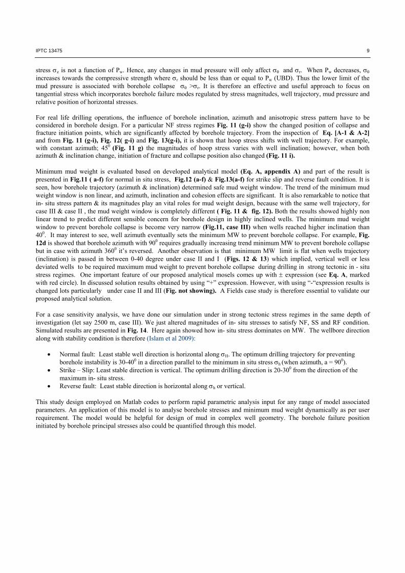
stress z is not a function of Pw. Hence, any changes in mud pressure will only affect and r. When Pw decreases,
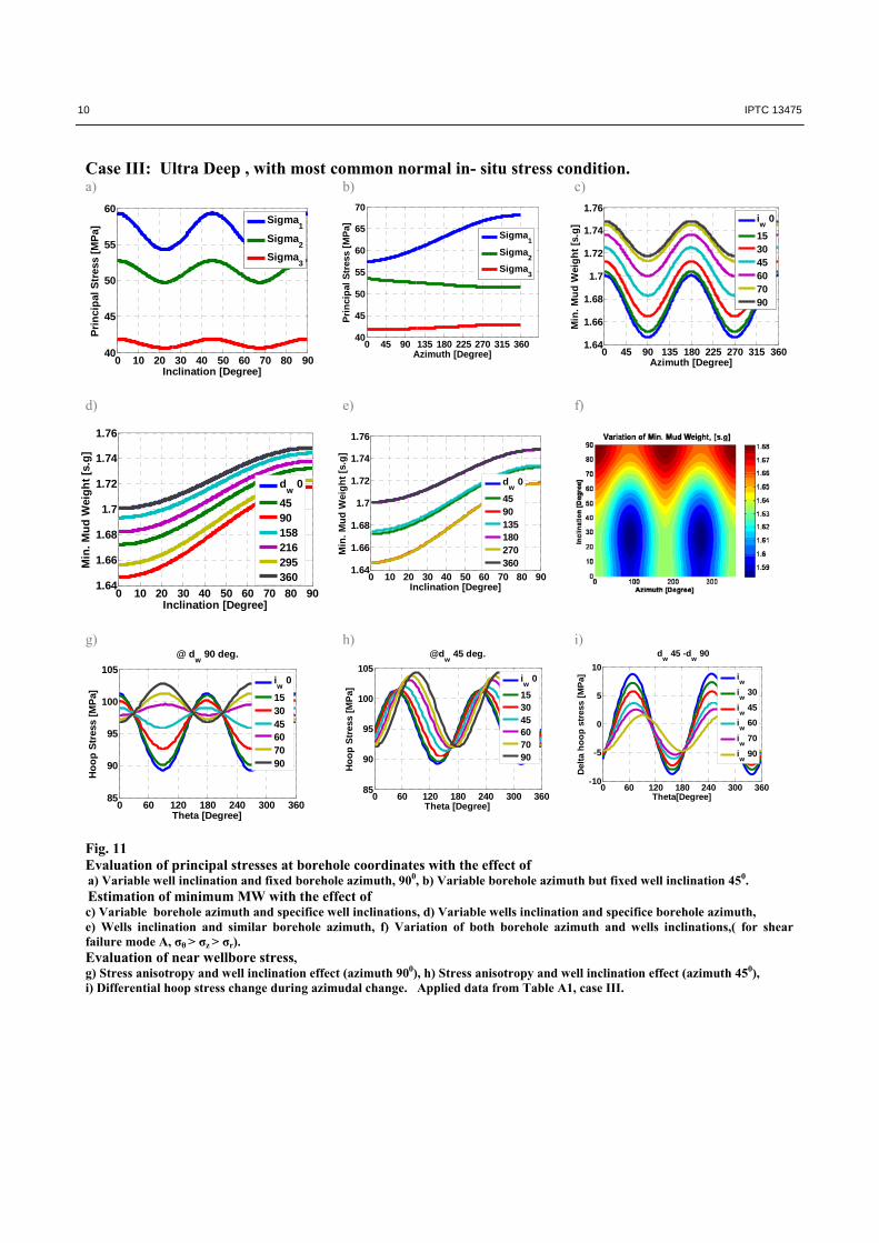
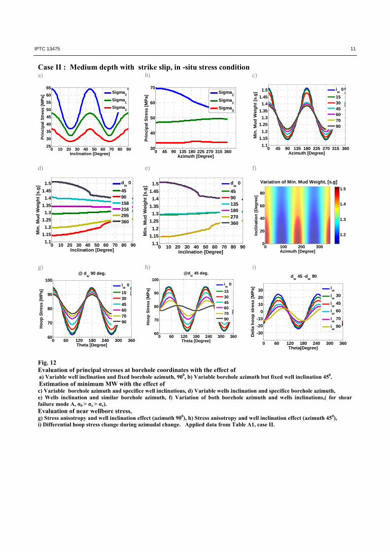
increases towards the compressive strength where r should be less than or equal to Pw (UBD). Thus the lower limit of the mud pressure is associated with borehole collapse >r. It is therefore an effective and useful approach to focus on tangential stress which incorporates borehole failure modes regulated by stress magnitudes, well trajectory, mud pressure and relative position of horizontal stresses. For real life drilling operations, the influence of borehole inclination, azimuth and anisotropic stress pattern have to be considered in borehole design. For a particular NF stress regimes Fig. 11 (g-i) show the changed position of collapse and fracture initiation points, which are significantly affected by borehole trajectory. From the inspection of Eq. [A-1 & A-2] and from Fig. 11 (g-i), Fig. 12( g-i) and Fig. 13(g-i), it is shown that hoop stress shifts with well trajectory. For example, with constant azimuth; 450 (Fig. 11 g) the magnitudes of hoop stress varies with well inclination; however, when both azimuth & inclination change, initiation of fracture and collapse position also changed (Fig. 11 i). Minimum mud weight is evaluated based on developed analytical model (Eq. A, appendix A) and part of the result is presented in Fig.11 ( a-f) for normal in situ stress, Fig.12 (a-f) & Fig.13(a-f) for strike slip and reverse fault condition. It is seen, how borehole trajectory (azimuth & inclination) determined safe mud weight window. The trend of the minimum mud weight window is non linear, and azimuth, inclination and cohesion effects are significant. It is also remarkable to notice that in- situ stress pattern & its magnitudes play an vital roles for mud weight design, because with the same well trajectory, for case III & case II , the mud weight window is completely different ( Fig. 11 & fig. 12). Both the results showed highly non linear trend to predict different sensible concern for borehole design in highly inclined wells. The minimum mud weight window to prevent borehole collapse is become very narrow (Fig.11, case III) when wells reached higher inclination than 400. It may interest to see, well azimuth eventually sets the minimum MW to prevent borehole collapse. For example, Fig. 12d is showed that borehole azimuth with 900 requires gradually increasing trend minimum MW to prevent borehole collapse but in case with azimuth 3600 it’s reversed. Another observation is that minimum MW limit is flat when wells trajectory (inclination) is passed in between 0-40 degree under case II and I (Figs. 12 & 13) which implied, vertical well or less deviated wells to be required maximum mud weight to prevent borehole collapse during drilling in strong tectonic in - situ stress regimes. One important feature of our proposed analytical mosels comes up with expression (see Eq. A, marked with red circle). In discussed solution results obtained by using “+” expression. However, with using “-“expression results is changed lots particularly under case II and III (Fig. not showing). A Fields case study is therefore essential to validate our proposed analytical solution. For a case sensitivity analysis, we have done our simulation under in strong tectonic stress regimes in the same depth of investigation (let say 2500 m, case III). We just altered magnitudes of in- situ stresses to satisfy NF, SS and RF condition. Simulated results are presented in Fig. 14. Here again showed how in- situ stress dominates on MW. The wellbore direction along with stability condition is therefore (Islam et al 2009):
Normal fault: Least stable well direction is horizontal along H. The optimum drilling trajectory for preventing borehole instability is 30-400 in a direction parallel to the minimum in situ stress h (when azimuth, a = 900).
Strike – Slip: Least stable direction is vertical. The optimum drilling direction is 20-300 from the direction of the maximum in- situ stress.
Reverse fault: Least stable direction is horizontal along h or vertical. This study design employed on Matlab codes to perform rapid parametric analysis input for any range of model associated parameters. An application of this model is to analyse borehole stresses and minimum mud weight dynamically as per user requirement. The model would be helpful for design of mud in complex well geometry. The borehole failure position initiated by borehole principal stresses also could be quantified through this model.
10 IPTC 13475
0 10 20 30 40 50 60 70 80 901.64
1.66
1.68
1.7
1.72
1.74
1.76
Inclination [Degree]
Min
. M
ud
Wei
gh
t [s
.g]
dw
0
4590135180270360
Case III: Ultra Deep , with most common normal in- situ stress condition. a) b) c)
d) e) f)
g) h) i)
Fig. 11 Evaluation of principal stresses at borehole coordinates with the effect of a) Variable well inclination and fixed borehole azimuth, 900, b) Variable borehole azimuth but fixed well inclination 450. Estimation of minimum MW with the effect of c) Variable borehole azimuth and specifice well inclinations, d) Variable wells inclination and specifice borehole azimuth, e) Wells inclination and similar borehole azimuth, f) Variation of both borehole azimuth and wells inclinations,( for shear failure mode A, σθ > σz > σr). Evaluation of near wellbore stress, g) Stress anisotropy and well inclination effect (azimuth 900), h) Stress anisotropy and well inclination effect (azimuth 450), i) Differential hoop stress change during azimudal change. Applied data from Table A1, case III.
0 45 90 135 180 225 270 315 3601.64
1.66
1.68
1.7
1.72
1.74
1.76
Azimuth [Degree]
Min
. M
ud
Wei
gh
t [s
.g]
iw
0
153045607090
0 45 90 135 180 225 270 315 36040
45
50
55
60
65
70
Azimuth [Degree] P
rin
cip
al S
tres
s [M
Pa]
Sigma1
Sigma2
Sigma3
0 10 20 30 40 50 60 70 80 9040
45
50
55
60
Inclination [Degree]
Pri
nci
pal
Str
ess
[MP
a]
Sigma1
Sigma2
Sigma3
0 10 20 30 40 50 60 70 80 901.64
1.66
1.68
1.7
1.72
1.74
1.76
Inclination [Degree]
Min
. M
ud
Wei
gh
t [s
.g]
dw
0
4590158216295360
0 60 120 180 240 300 36085
90
95
100
105
Theta [Degree]
Ho
op
Str
ess
[MP
a]
@ dw
90 deg.
iw
0
153045607090
0 60 120 180 240 300 36085
90
95
100
105
Theta [Degree]
Ho
op
Str
ess
[MP
a]
@dw
45 deg.
iw
0
153045607090
0 60 120 180 240 300 360-10
-5
0
5
10
Theta[Degree]
Del
ta h
oo
p s
tres
s [M
Pa]
dw
45 -dw
90
iw
iw
30
iw
45
iw
60
iw
70
iw
90
IPTC 13475 11
0 45 90 135 180 225 270 315 36030
40
50
60
70
Azimuth [Degree]
Pri
nci
pal
Str
ess
[MP
a]
Sigma2
Sigma1
Sigma3
0 10 20 30 40 50 60 70 80 9025
30
35
40
45
50
55
60
65
Inclination [Degree]
Pri
nci
pal
Str
ess
[MP
a]
Sigma2
Sigma1
Sigma3
Case II : Medium depth with strike slip, in -situ stress condition a) b) c)
d) e) f)
g) h) i)
Fig. 12 Evaluation of principal stresses at borehole coordinates with the effect of a) Variable well inclination and fixed borehole azimuth, 900, b) Variable borehole azimuth but fixed well inclination 450. Estimation of minimum MW with the effect of c) Variable borehole azimuth and specifice well inclinations, d) Variable wells inclination and specifice borehole azimuth, e) Wells inclination and similar borehole azimuth, f) Variation of both borehole azimuth and wells inclinations,( for shear failure mode A, σθ > σz > σr). Evaluation of near wellbore stress, g) Stress anisotropy and well inclination effect (azimuth 900), h) Stress anisotropy and well inclination effect (azimuth 450), i) Differential hoop stress change during azimudal change. Applied data from Table A1, case II.
0 60 120 180 240 300 360
-30
-20
-10
0
10
20
30
Theta[Degree]
Del
ta h
oo
p s
tres
s [M
Pa]
dw
45 -dw
90
iw
iw
30
iw
45
iw
60
iw
70
iw
90
0 60 120 180 240 300 36060
70
80
90
100
Theta [Degree]
Ho
op
Str
ess
[MP
a]
@dw
45 deg.
iw
0
153045607090
0 60 120 180 240 300 36060
70
80
90
100
Theta [Degree]
Ho
op
Str
ess
[MP
a]
@ dw
90 deg.
iw
0
153045607090
0 10 20 30 40 50 60 70 80 901.1
1.15
1.2
1.25
1.3
1.35
1.4
1.45
1.5
Inclination [Degree]
Min
. M
ud
Wei
gh
t [s
.g]
dw
0
4590135180270360
0 10 20 30 40 50 60 70 80 901.1
1.15
1.2
1.25
1.3
1.35
1.4
1.45
1.5
Inclination [Degree]
Min
. M
ud
Wei
gh
t [s
.g]
dw
0
4590158216295360
0 45 90 135 180 225 270 315 3601.1
1.15
1.2
1.25
1.3
1.35
1.4
1.45
1.5
Azimuth [Degree]
Min
. M
ud
Wei
gh
t [s
.g]
iw
0
153045607090
0 100 200 3000
20
40
60
80
Azimuth [Degree] I
ncl
inat
ion
[D
egre
e]
Variation of Min. Mud Weight, [s.g]
1.2
1.3
1.4
1.5
12 IPTC 13475
0 10 20 30 40 50 60 70 80 9015
20
25
30
35
40
Inclination [Degree]
Pri
nci
pal
Str
ess
[MP
a]
Sigma2
Sigma3
Sigma1
0 60 120 180 240 300 36040
45
50
55
60
Theta [Degree]
Ho
op
Str
ess
[MP
a]
@dw
45 deg.
iw
0
153045607090
0 100 200 3000
20
40
60
80
Azimuth [Degree] I
ncl
inat
ion
[D
egre
e]
Variation of Min. Mud Weight, [s.g]
0.75
0.8
0.85
0.9
0.95
Case I : Shallow depth with reverse fault condition a) b) c)
d) e) f)
Fig. 13 Evaluation of principal stresses at borehole coordinates with the effect of a) Variable well inclination and fixed borehole azimuth, 900, b) Variable borehole azimuth but fixed well inclination 450. Estimation of minimum MW with the effect of c) Variable borehole azimuth and specifice well inclinations, d) Variable wells inclination and specifice borehole azimuth, e) Wells inclination and similar borehole azimuth, f) Variation of both borehole azimuth and wells inclinations,( for shear failure mode A, σθ > σz > σr). Evaluation of near wellbore stress, g) Stress anisotropy and well inclination effect (azimuth 900), h) Stress anisotropy and well inclination effect (azimuth 450), i) Differential hoop stress change during azimudal change. Applied data from Table A1, case I.
a) b) c)
0 45 90 135 180 225 270 315 36015
20
25
30
35
40
45
Azimuth [Degree]
Pri
nci
pal
Str
ess
[MP
a]
Sigma2
Sigma3
Sigma1
0 60 120 180 240 300 36040
45
50
55
60
Theta [Degree]
Ho
op
Str
ess
[MP
a]
@ dw
90 deg.
iw
0
153045607090
0 60 120 180 240 300 360-12
-8
-4
0
4
8
12
Theta[Degree]
Del
ta h
oo
p s
tres
s [M
Pa]
dw
45 -dw
90
iw
iw
30
iw
45
iw
60
iw
70
iw
90
0 45 90 135 180 225 270 315 3600.72
0.76
0.8
0.84
0.88
0.92
0.96
Azimuth [Degree]
Min
. M
ud
Wei
gh
t [s
.g]
iw
0
153045607090
0 10 20 30 40 50 60 70 80 900.72
0.76
0.8
0.84
0.88
0.92
0.96
Inclination [Degree]
Min
. M
ud
Wei
gh
t [s
.g]
dw
0
4590158216295360
0 10 20 30 40 50 60 70 80 900.72
0.76
0.8
0.84
0.88
0.92
0.96
Inclination [Degree]
Min
. M
ud
Wei
gh
t [s
.g]
dw
0
4590135180270360
IPTC 13475 13
V
Hh
V
Hh
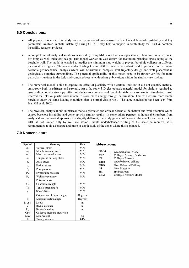
Fig.15 Loads applied to the model
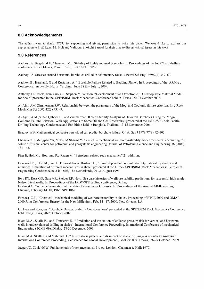
Fig.16 Boundary condition in a horizontal plane.
0 100 200 3000
20
40
60
80
Azimuth [Degree]
In
clin
atio
n [
Deg
ree]
Variation of Min. MW, SS, [s.g]
1.6
1.65
1.7
1.75
0 100 200 3000
20
40
60
80
Azimuth [Degree]
In
clin
atio
n [
Deg
ree]
Variation of Min. MW, RF, [s.g]
1.6
1.62
1.64
1.66
1.68
1.7
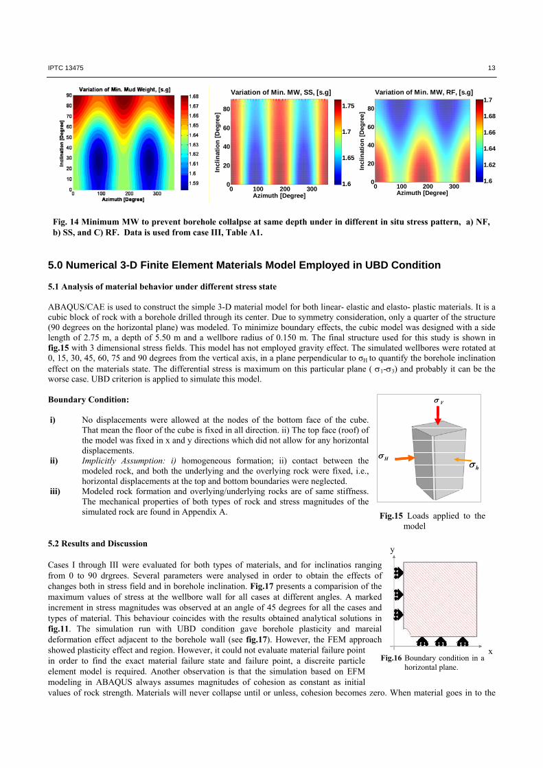
Fig. 14 Minimum MW to prevent borehole collalpse at same depth under in different in situ stress pattern, a) NF, b) SS, and C) RF. Data is used from case III, Table A1.
5.0 Numerical 3-D Finite Element Materials Model Employed in UBD Condition 5.1 Analysis of material behavior under different stress state ABAQUS/CAE is used to construct the simple 3-D material model for both linear- elastic and elasto- plastic materials. It is a cubic block of rock with a borehole drilled through its center. Due to symmetry consideration, only a quarter of the structure (90 degrees on the horizontal plane) was modeled. To minimize boundary effects, the cubic model was designed with a side length of 2.75 m, a depth of 5.50 m and a wellbore radius of 0.150 m. The final structure used for this study is shown in fig.15 with 3 dimensional stress fields. This model has not employed gravity effect. The simulated wellbores were rotated at 0, 15, 30, 45, 60, 75 and 90 degrees from the vertical axis, in a plane perpendicular to σH to quantify the borehole inclination effect on the materials state. The differential stress is maximum on this particular plane ( 1-3) and probably it can be the worse case. UBD criterion is applied to simulate this model. Boundary Condition: i) No displacements were allowed at the nodes of the bottom face of the cube.
That mean the floor of the cube is fixed in all direction. ii) The top face (roof) of the model was fixed in x and y directions which did not allow for any horizontal displacements.
ii) Implicitly Assumption: i) homogeneous formation; ii) contact between the modeled rock, and both the underlying and the overlying rock were fixed, i.e., horizontal displacements at the top and bottom boundaries were neglected.
iii) Modeled rock formation and overlying/underlying rocks are of same stiffness. The mechanical properties of both types of rock and stress magnitudes of the simulated rock are found in Appendix A.
5.2 Results and Discussion Cases I through III were evaluated for both types of materials, and for inclinatios ranging from 0 to 90 drgrees. Several parameters were analysed in order to obtain the effects of changes both in stress field and in borehole inclination. Fig.17 presents a comparision of the maximum values of stress at the wellbore wall for all cases at different angles. A marked increment in stress magnitudes was observed at an angle of 45 degrees for all the cases and types of material. This behaviour coincides with the results obtained analytical solutions in fig.11. The simulation run with UBD condition gave borehole plasticity and mareial deformation effect adjacent to the borehole wall (see fig.17). However, the FEM approach showed plasticity effect and region. However, it could not evaluate material failure point in order to find the exact material failure state and failure point, a discreite particle element model is required. Another observation is that the simulation based on EFM modeling in ABAQUS always assumes magnitudes of cohesion as constant as initial values of rock strength. Materials will never collapse until or unless, cohesion becomes zero. When material goes in to the
x
y

14 IPTC 13475
Fig.17 Numerical result of stresses at borehole wall under Normal in – situ stress stae condition. Elastic and elastoplastic material behaviour were quantified.
Borehole Stress
-70000
-60000
-50000
-40000
-30000
-20000
-10000
0
10000
0 2 4 6 8
Radial distance
Str
ess M
ag
nitu
des,
KP
a
radial
tangential
plastic zone, cohesion might be reduced. Moreover, pore pressure simulated trend in fig. 18c is in good agreement with developed pore pressure evaluation model (fig.9).
a)
b)
c)
Fig.18 Material failure state, a) Plasticity effect, b) Borehole displacement, c) Instantaneous pore pressure trend. Data are from Table1, case III
Plasticity effect
0 10 20 30 40 50 60 70 80 9010
20
30
40
50
60
70
80
90
Borehole Inclination, degree
S
tres
s a
t B
ore
ho
le w
all,
MP
a
Maximum stress at borehole
elastic3
ep3
elastic2
ep2
elastic1
ep1
Borehole Displacement
-0.01
-0.008
-0.006
-0.004
-0.002
0
0 1 2 3 4 5 6
Radial Distance to Borehole
Dis
pla
ce
me
nt,
str
ain
Pore Pressure Trend
05000
1000015000200002500030000350004000045000
0 1 2 3 4 5 6Radial Distance to Borehole
Po
re P
res
su
re, K
Pa
IPTC 13475 15
6.0 Conclusions:
All physical models in this study give an overview of mechanisms of mechanical borehole instability and key parameters involved in shale instability during UBD. It may help to support in-depth study for UBD & borehole instability research projects.
A complete set of analytical solutions is solved by using M-C model to develop a standard borehole collapse model
for complex well trajectory design. This model worked in well design for maximum principal stress acting at the borehole wall. The model is enabled to predict the minimum mud weight to prevent borehole collapse in different in- situ stress regimes. The considerable leading feature of this model is to evaluate and to provide more accurate borehole geomechanical analysis which will be useful in complex well trajectory design and well placement in geologically complex surroundings. The potential applicability of this model need to be further verified for more particular situations in the field and compared results with othors publications within the similar case studies.
The numerical model is able to capture the effect of plasticity with a certain limit, but it did not quantify material
anisotropy both in stiffness and strength. An orthotropic 3-D elastoplastic material model for shale is required to ensure directional anisotropy effect of shales to compare real borehole stability case studis. Simulation result inferred that elasto- plastic rock is able to store more energy through deformation. This will ensure more stable borehole under the same loading conditions than a normal elastic rock. The same conclusion has been seen from Ivan Gil et al. 2002.
The physical, analytical and numerical models predicted the critical borehole inclination and well direction which
caused borehole instability and come up with similar results. In some others perspect, although the numbers from analytical and numerical approach are slightly different, the study gave confidence in the conclusion that OBD or UBD is not limited only by well inclination. Should underbalanced drilling of the shale be required, it is recommended to do a separate and more in-depth study of the zones where this is planned.
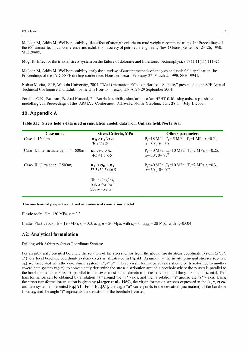
7.0 Nomenclature
Symbol Meaning Unit σV Vertical stress MPa σh Min. horizontal stress MPa σH Max. horizontal stress MPa σθ Tangential or hoop stress MPa σz Axial stress MPa σr Radial stress MPa Pp Pore pressure MPa Pfh Hydrostatic pressure MPa Pw Wellbore pressure MPa Poisons ratios Co Cohesion strength MPa To Tensile strength; Pa MPa Shear stress MPa
Orientation of failure angle Degrees α Material friction angle Degrees
D or h Depth m r Radial distance m
Rw Borehole radius m CPP Collapse pressure prediction MW Mud weight s.g
E Young modulud GPa
Abbreviation:
GMM : Geomechanical Model CPP : Collapse Pressure Prediction CP : Collapse Pressure UBD : underbalanced drilling OBD : Over Balanced Drilling OP : Over Pressure HC : Hydrocarbon CPM : Collapse Pressure Model
16 IPTC 13475
8.0 Acknowledgements The authors want to thank NTNU for supporting and giving permission to write this paper. We would like to express our appreciation to Prof. Rune. M. Holt and Valipour Shokohi Samad for their time to discuss critical issues in this work. 9.0 References Aadnoy BS, Rogaland U, Chenevert ME. Stability of highly inclined boreholes. In Proceedings of the IADC/SPE drilling conference, New Orleans, March 15–18, 1987. SPE 16052. Aadnoy BS. Stresses around horizontal boreholes drilled in sedimentary rocks. J Petrol Sci Eng 1989;2(4):349–60. Aadnoy, B., Hareland, G and Kustamsi, A. “ Borehole Failure Related to Bedding Plane”. In Proceedings of the ARMA , Conference, Asheville, North Carolina, June 28 th – July 1, 2009. Anthony J.L Crook, Jian- Guo Yu, Stephen M. Willson “Development of an Orthotropic 3D Elastoplastic Material Model for Shale” presented in the SPE/ISRM Rock Mechanics Conference held in Texas , 20-23 October 2002. Al-Ajmi AM, Zimmerman RW. Relationship between the parameters of the Mogi and Coulomb failure criterion. Int J Rock Mech Min Sci 2005;42(3):431–9. Al-Ajmi, A.M.,Sultan Qaboos U,; and Zimmerman, R.W.” Stability Analysis of Deviated Boreholes Using the Mogi-Coulomb Failure Criterion, With Applications to Some Oil and Gas Reservoirs” presented at the IADC/SPE Asia Pacific Drilling Technology Conference and Exhibition held in Bangkok, Thailand, 13-15 November 2006. Bradley WB. Mathematical concept-stress cloud can predict borehole failure. Oil & Gas J 1979;77(8):92–102. Chenevert E, Mengjiao Yu, Mukul M Sharma “ Chemical – mechanical wellbore instability model for shales: accounting for solute diffusion” center for petroleum and geosystems engineering, Journal of Petroleum Science and Engineering 38 (2003) 131-143. Fjær E, Holt M., Hoursrud P., Raaen M “Petroleum related rock mechanics” 2nd addition, Hoursrud, P., Holt M., and E. F. Sonstebo, & Bostrom B., “ Time dependent borehole stability: laboratory studies and numerical simulation of different mechanisms in shale” presented at the Eurock SPE/ISRM Rock Mechanics in Petroleum Engineering Conference held in Delft, The Netherlands, 29-31 August 1994. Ewy RT, Ross GD, Gast MR, Steiger RP. North Sea case histories of wellbore stability predictions for successful high-angle Nelson Field wells. In: Proceedings of the IADC/SPE drilling conference, Dallas, Fairhurst C. On the determination of the state of stress in rock masses. In: Proceedings of the Annual AIME meeting, Chicago, February 14–18, 1965. SPE 1062. Fonseca C.F., “Chemical– mechanical modeling of wellbore instability in shales. Proceeding of ETCE 2000 and OMAE 2000 Joint Conference: Energy for the New Millenium, Feb. 14– 17, 2000, New Orleans, LA.
Gil Ivan and Roegiers, “Borehole Design: Stability Considerations” presented at the SPE/ISRM Rock Mechanics Conference held inving Texas, 20-23 October 2002. Islam M.A , Skalle P., and Tantserev E., “ Prediction and evaluation of collapse pressure risk for vertical and horizontal wells in undervalanced drilling in shales” International Conference Proceeding, International Conference of mechanical Engineering ( ICME,09), Dhaka, 28-30 December 2009. Islam M.A, Skalle P and Mahmud H., “ In situ stress pattern and its impact on stable drilling – A sensitivity Analysis” Internationa Conference Proceeding, Geoscience for Global Development ( GeoDev, 09) , Dhaka, 26-29 October , 2009. Jaeger JC, Cook NGW. Fundamentals of rock mechanics. 3rd ed. London: Chapman & Hall; 1979.
IPTC 13475 17
McLean M, Addis M. Wellbore stability: the effect of strength criteria on mud weight recommendations. In: Proceedings of the 65th annual technical conference and exhibition, Society of petroleum engineers, New Orleans, September 23–26, 1990. SPE 20405. Mogi K. Effect of the triaxial stress system on the failure of dolomite and limestone. Tectonophysics 1971;11(11):111–27. McLean M, Addis M. Wellbore stability analysis: a review of current methods of analysis and their field application. In: Proceedings of the IADC/SPE drilling conference, Houston, Texas, February 27–March 2, 1990. SPE 19941. Nobuo Morita, SPE, Waseda University, 2004. “Well Orientation Effect on Borehole Stability” presented at the SPE Annual Technical Conference and Exhibition held in Houston, Texas, U.S.A, 26-29 September 2004. Søreide O.K., Bostrøm, B. And Horsrud, P “ Borehole stability simulations of an HPHT field using anisotropic shale modelling”, In Proceedings of the ARMA , Conference, Asheville, North Carolina, June 28 th – July 1, 2009. 10. Appendix A Table A1: Stress field’s data used in simulation model: data from Gulfask field, North Sea.
Case name Stress Criteria, MPa Others parameters Case-1, 1200 m VhH σσσ
302524 Pp=18 MPa, C0= 5 MPa , To=1 MPa, =0.2 , = 300, , = 900
Case-II, Intermediate depth ( 1800m) hVH σσσ 4641.535
Pp=30 MPa, C0=10 MPa , To=2 MPa, =0.25, = 300, = 900,
Case-III, Ultra deep (2500m) hHV σσσ 52.550.546.5 NF : 1>2>3 SS: 2>1>3 SS: 2>3>1
Pp=40 MPa ,C0=10 MPa , To=2 MPa, =0.3 , = 300, = 900
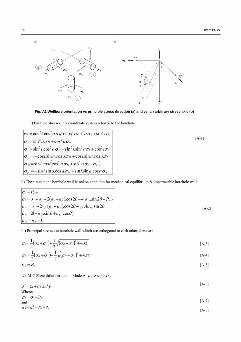
The mechanical properties: Used in numerical simulation model Elastic rock: E = 120 MPa, = 0.3 Elasto- Plastic rock: E = 120 MPa, = 0.3, σyield o = 20 Mpa, with p=0, σyield = 28 Mpa, with p=0.004 A2: Analytical formulation Drilling with Arbitrary Stress Coordinate System: For an arbitrarily oriented borehole the rotation of the stress tensor from the global in-situ stress coordinate system (x*,y*, z*) to a local borehole coordinate system(x,y,z) as illustrated in Fig.A1. Assume that the in situ principal stresses (V, H, h) are associated with the co-ordinate system (x*,y* z*). These virgin formation stresses should be transformed to another co-ordinate system (x,y,z), to conveniently determine the stress distribution around a borehole where the z- axis is parallel to the borehole axis, the x-axis is parallel to the lower most radial direction of the borehole, and the y- axis is horizontal. This transformation can be obtained by a rotation “a” around the “y*”-axis, and then a rotation “i” around the “z*”- axis. Using the stress transformation equation is given by (Jaeger et al., 1969), the virgin formation stresses expressed in the (x, y, z) co-ordinate system is presented Eq.[A1]. From Eq.[A1], the angle “a” corresponds to the deviation (inclination) of the borehole from H, and the angle “i” represents the deviation of the borehole from V.
18 IPTC 13475
a) b)
Fig. A1 Wellbore orientation vs principle stress direction (a) and vs. an arbitrary stress axis (b)
i) Far field stresses in a coordinate system referred to the borehole.
hHyz
VhHxz
hHxy
VhHz
hHy
VhHx
aaiaai
aaii
aaiaai
iaiai
aa
iaiai
..cossin.sin..cossin.sin
.sin.cos.cossin
..cossin.cos..cossin.cos
cossin.sin..cossin
.cos.sin
.sin.sin.cos..coscos
22
22222
22
22222
σ
ii) The stress at the borehole wall based on condition for mechanical equilibrium & impermeable borehole wall:
0
cossin2
2sin42cos2
2sin42cos2
rzrθ
yzxzθz
xyfryxfrzzz
wellxyyxyxθ
wellr
σσ
θ.σθ.σσ
θ.σ.νθ.σσ.νσσ
Ρθ..σθ.σσσσσ
Pσ
iii) Proncipal stresses at borehole wall which are orthogonal to each other; these are
221 4
2
1
2
1zzz
222 4
2
1
2
1zzz
wP3
iv) M-C Shear failure criteria: Mode A: rZσ
2/30
/1 tanC
Where;
f 1/
1 and
fwr P 1/3
[A-1]
[A-2]
[A-3]
[A-4]
[A-5]
[A-6]
[A-7]
[A-8]
V
h
H H
V
h H
h
V
I
III
II
Z*
Y*
X*
V
h
z
x
y
a
i
H
IPTC 13475 19
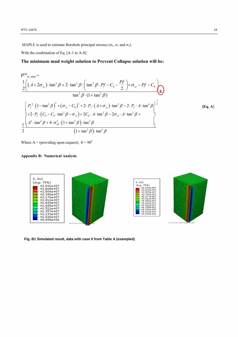
Fig. B1 Simulated result, data with case II from Table A (exampled)
MAPLE is used to estimate Borehole principal stresses (σ1, σ1 and σ3). With the combination of Eq. [A-1 to A-8]: The minimum mud weight solution to Prevent Collapse solution will be:
P(a)
w, min =
2 2 20 0
2 2
12 tan 2 tan tan
2 2
tan (1 tan )
zz zz
PfA Pf C Pf C
±
12 2 22 2 2 4
0
2 2 20 0 0
2 4 2 2 2
2 2
1 tan 2 tan 2 tan
2 tan 2 tan 2 tan
tan 4 1 tan tan1
2 1 tan tan
f zz f zz f
f zz zz
z
P C P A P A
P C C C A A
A
Where A = (providing upon request); = 900 Appendix B: Numerical Analysis
[Eq. A]