Embed Size (px)
DESCRIPTION
Kalibrasi
Citation preview

CALIBRATION OF DIGITAL CONSUMER CAMERAS FOR PHOTOGRAMMETRIC APPLICATIONS
Dr.-Ing. Manfred Wiggenhagen,
Institute for Photogrammetry and GeoInformation, University of Hannover,
Nienburger Str. 1, D-30167 Hannover, Germany [email protected]
Commission III, WG 5
KEY WORDS: Digital, Photogrammetry, Calibration ABSTRACT: This paper presents the results of a modified calibration method for the calculation of the interior orientation of digital consumer cameras. With a two-dimensional calibration field and the use of the CameraCalibrator 4.0 and PhotoModeler 4.0 software from EOS Systems Inc. an efficient and fast calculation method has been applied. The calibration results of the digital cameras Olympus E-10 and Nikon Coolpix 990 have been verified by repeated calibrations and the additional adjustment with the bundle adjustment software CAP. To show the important effect of full field calibration the results of a project are presented before and after calibration. KURZFASSUNG: Dieser Beitrag beschreibt die Ergebnisse einer modifizierten Kalibriermethode zur Berechnung der inneren Orientierung digitaler Gebrauchskameras. Mittels eines zweidimensionalen Testfeldes und der Software „CameraCalibrator 4.0“ sowie "PhotoModeler 4.0" von EOS Systems Inc. wurde eine wirtschaftliche und schnelle Berechnungsmethode eingesetzt. Die Kalibrierungsergebnisse für die Digitalkameras Olympus E-10 und Nikon Coolpix 990 wurden durch wiederholte Kalibrierungen und die zusätzliche Ausgleichung mit dem Bündelausgleichungsprogramm CAP überprüft. Um den wichtigen Effekt einer Feldkalibrierung zu demonstrieren, werden die Ergebnisse eines Projektes vor und nach der Kalibrierung vorgestellt.
1. INTRODUCTION
Digital high resolution consumer cameras have found large interest among photogrammetrists during the past few years. For current projects the Institute for Photogrammetry and GeoInformation of the University of Hannover (IPI) has tested several mirror reflex cameras as well as consumer digital cameras. For high precision output the cameras have to be calibrated with very high accuracy. This paper will clarify, whether a two-dimensional calibration field is sufficient for the calibration of photogrammetric digital cameras or not.
2. TECHNICAL DATA OF THE USED CAMERAS
The following digital cameras have been investigated.
2.1 Olympus E-10
Following the general tendency of higher resolution and more functionality the manufacturer Olympus offers today the improved camera model E-20. Table 1 compares some of the important parameters of the new model E-20 with the version E-10 which has been used in the tests at IPI.
E-20 E-10 Sensor pixels 5.2 megapixel 4.0 megapixel Output pixels 4.9 megapixel 3.8 megapixel Maximum image sizes
2560x1920 pixel 2240x1680 pixel
Image formats JPEG,TIF,RAW JPEG,TIF,RAW Exposure Modes
P, A, S, M P, A, S, M
Normal focus range
0.6 m - infinity 0.6 m - infinity
Macro focus range
0.2 m – 0.6 m 0.2 m – 0.6 m
Manual focus range
0.2 m - infinity 0.2 m - infinity
Smart media support
4 – 128 MB 4 – 128 MB
Compact flash support
up to 320 MB up to 320 MB
Table 1. Technical specification Olympus E-10/20
Important for the photogrammetric use is the manual exposure mode and the possibility to store the digital images without compression.
2.2 Nikon Coolpix 990 The compact digital camera Nikon Coolpix 990 has been choosen for architectural applications as well as for optical measurements of macro objects. The Coolpix 990 is equipped with a 3.34 megapixel sensor and stores the digital photos with a maximum image size of 2048 x 1536 pixels on a CompactFlash memory card. Using TIF format the images are uncompressed. The manual exposure mode was used for the investigations of this paper. 2.3 Kodak DCS 460 Since 1995 the Kodak DCS 460 is well known as one of Kodak's high-end models beside the newer DCS 660 and 760 (Maas, 1997). It is based on a Nikon N90 camera body with a 3060 x 2036 pixel Kodak CCD sensor with 9 µm pixel size. The camera has been calibrated several times with high accuracy using a three- and two-dimensional calibration field and was applied for the calculation of reference coordinates to verify the adjusted coordinates of the two consumer cameras.
3. SOFTWARE APPLICATION
For the camera calibration and the calculation of three-dimensional object coordinates the software modules CameraCalibrator 4.0 and PhotoModeler 4.0 from Eos Systems Inc. have been used (EOS, 2002). The following chapter describes the theory of the implemented calibration method and the functionality of the software modules.
3.1 Calibration
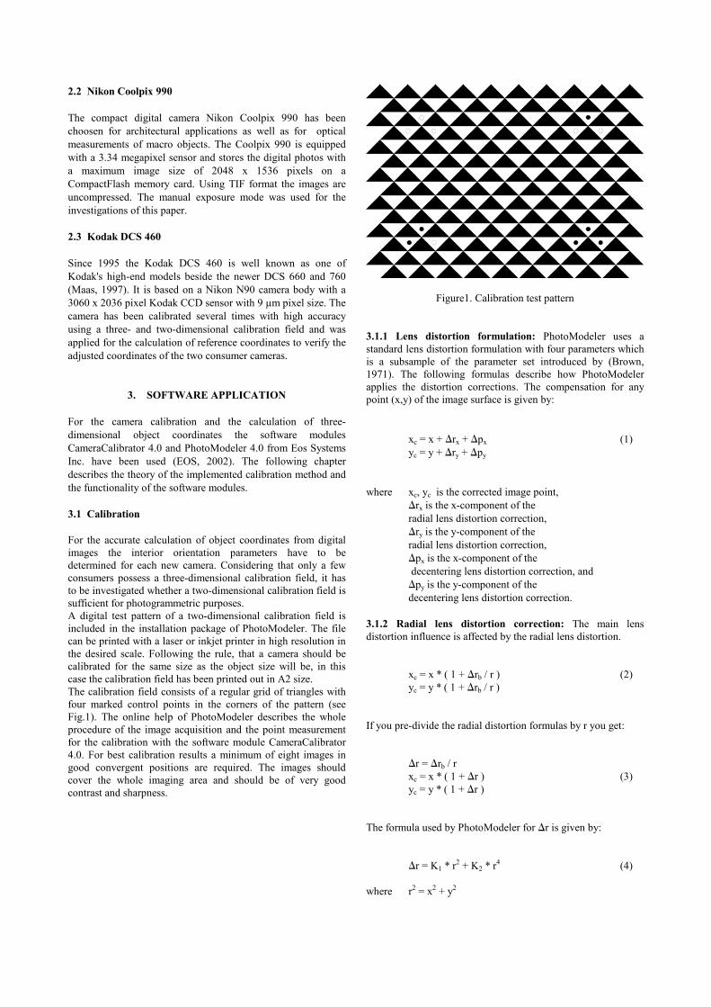
For the accurate calculation of object coordinates from digital images the interior orientation parameters have to be determined for each new camera. Considering that only a few consumers possess a three-dimensional calibration field, it has to be investigated whether a two-dimensional calibration field is sufficient for photogrammetric purposes. A digital test pattern of a two-dimensional calibration field is included in the installation package of PhotoModeler. The file can be printed with a laser or inkjet printer in high resolution in the desired scale. Following the rule, that a camera should be calibrated for the same size as the object size will be, in this case the calibration field has been printed out in A2 size. The calibration field consists of a regular grid of triangles with four marked control points in the corners of the pattern (see Fig.1). The online help of PhotoModeler describes the whole procedure of the image acquisition and the point measurement for the calibration with the software module CameraCalibrator 4.0. For best calibration results a minimum of eight images in good convergent positions are required. The images should cover the whole imaging area and should be of very good contrast and sharpness.
Figure1. Calibration test pattern 3.1.1 Lens distortion formulation: PhotoModeler uses a standard lens distortion formulation with four parameters which is a subsample of the parameter set introduced by (Brown, 1971). The following formulas describe how PhotoModeler applies the distortion corrections. The compensation for any point (x,y) of the image surface is given by:
xc = x + rx + px (1) yc = y + ry + py
where xc, yc is the corrected image point,
rx is the x-component of the radial lens distortion correction,
ry is the y-component of the radial lens distortion correction,
px is the x-component of the decentering lens distortion correction, and
py is the y-component of the decentering lens distortion correction.
3.1.2 Radial lens distortion correction: The main lens distortion influence is affected by the radial lens distortion.
xc = x * ( 1 + rb / r ) (2) yc = y * ( 1 + rb / r )
If you pre-divide the radial distortion formulas by r you get:
r = rb / r xc = x * ( 1 + r ) (3) yc = y * ( 1 + r )
The formula used by PhotoModeler for r is given by:
r = K1 * r2 + K2 * r4 (4) where r2 = x2 + y2

The standard balanced form for radial lens distortion is:
r = A0 + A1 * r2 + A2 * r4 (5) To convert this balanced form to PhotoModeler's unbalanced form you use:
s = (1 - A0) (6) f = f2 / s K1 = A1 / s K2 = A2 / s
where f2 is the focal length (principal distance) given in the original calibration with the balanced distortion and f is the focal length to be used in PhotoModeler. To convert PhotoModeler's unbalanced form to the balanced one you need to determine the balancing point defined by r0
A0 = - ( K1 * r02 + K2 * r0
4 ) s = (1 - A0) (7) f2 = f * s A1 = K1 * s A2 = K2 * s
3.1.3 Decentering lens distortion: The decentering distortion is often not modeled because its contribution is much smaller than the radial lens distortion. But for highest accuracy measurements it has to be considered. The formulas used by PhotoModeler for decentering lens distortion are:
px = P1 * (r2 + 2 * x2 ) + 2 * P2 * x * y (8) py = P2 * (r2 + 2 * y2 ) + 2 * P1 * x * y
3.2 Semi-automatic calibration In a new calibration project initial values for following parameters of the digital camera are required:
• focal length, • format width, format height, • x- and y- coordinate of the principal point, • image width and image height.
Considering following formulas it is possible to calculate the physical pixel size by measuring distances in object and image space:
pex = ( f * Sx ) / ( Z * sx' ) (9) pey = ( f * Sy ) / ( Z * sy' )
where pex and pey are the calculated pixel sizes
in x- and y-direction, f the used focal length,
Sx and Sy are known horizontal and vertical scales in object space, Z is the distance of the camera from the scales, and sx' and sy' are measured distances in image space.
PhotoModeler's online help suggests following steps to calculate the starting values of the CCD-sensor: 1.Take a picture of a piece of paper stuck to a wall. 2.Enter the distance the camera was from the piece of paper when the photo was taken. 3.Import and then mark the corners of this piece of paper using the wizard. With the known dimensions of the piece of paper, the used focal length and the measured distances in the image, the calibration software calculates the desired pixel size and CCD-format. For the calibration at least eight photos of the calibration target have to be taken. The camera positions should be close to 45 degrees from the horizontal and vertical to consider stable image bundles. After introducing the measured distance between two control points of the calibration target the user only has to mark the four control points in each image. The detection of tiepoints and calculation of the interior orientation parameters will be performed automatically. The calibration results are stored to use the calibrated digital camera in following projects. 3.3 Full field calibration The PhotoModeler 4.0 software also offers the possibility to calculate the interior orientation parameters by full field calibration. Minimizing the residuals in all tiepoints a good point distribution is required for a significant calculation of the lens distortion coefficients. Fig.2 shows the residuals before and after the full field calibration for the Olympus E-10.
Figure 2. Residuals before (on the top) and after (bottom) the full field calibration

Figure 3. Control distances of the test field
The results of this software module are still under investigation and will be published in the near future.
4. EXAMPLES The three-dimensional test field (see Fig.2) has been used for the verification of the results of the two consumer cameras Olympus E-10 and Nikon Coolpix 990 and the DCS 460 with a Nikkor 20 mm lens. The calculation of all image coordinates has been carried out with PhotoModeler's automatic point marking function which uses least squares matching methods to detect the white signalized dots in the images. To investigate the accuracy of the different digital cameras ten control distances have been defined and compared (see Fig.3).
4.1 Results of the calibration tests
Eight photos have been taken of the test field with each camera. 42 tiepoints have been measured with subpixel accuracy with Photomodeler's automatic target marking function. After the calculation of the exterior orientations of all images with a minimum of six tiepoints all other object points have been measured by the automatic referencing function. The adjustment has been carried out with pre-calibrated cameras. Normally the resulting three-dimensional object coordinates should be compared to detect systematic errors or to investigate the differences between several adjustments. In this case the definition of control distances has been chosen because PhotoModeler is only able to merge the coordinates of several projects, but will not process differences between the two data sets. The calculated differences between the measured distances and the control distances have been determined for all three cameras and are listed in the Table 2. The mean absolute differences between 0.038 and 0.064 mm are very good results for the tested cameras. The distances from number 1 to number 7 are horizontal controls (see Fig. 3). The distances 8 to 12 are near vertical or diagonal ones which are very sensible to errors in the calibration parameters. The last column of table 2 shows the result of such a poor calibration. 4.2 Verification of calibration results For the verification of the calibration results, the two consumer camera projects have been calculated with the bundle
adjustment program CAP, too. The software is more flexible as PhotoModeler and allows the adjustment of additional calibration parameters and observations but does not introduce extended parameter sets, as it is suggested by (Tecklenburg 2001). Therefore the interior orientation parameters adjusted with CAP were nearly identical with PhotoModeler's off-line calibration results.
distance DCS 460 Coolpix 990
E-10 E-10 decalib.
1 +0.046 -0.030 -0.043 -0.084 2 -0.067 -0.055 -0.092 -0.092 3 -0.035 -0.038 -0.083 -0.101 4 +0.057 +0.070 +0.039 -0.014 5 -0.018 -0.023 -0.062 -0.027 6 +0.019 -0.011 -0.012 -0.068 7 -0.050 -0.054 -0.077 -0.113 8 -0.046 -0.045 -0.087 -0.674 9 -0.070 -0.006 -0.095 -0.577
10 +0.006 -0.040 -0.079 -0.625 11 +0.022 +0.073 +0.055 -0.243 12 -0.020 -0.035 -0.042 -0.340
mean absolute
difference
0.038 mm
0.040 mm
0.064 mm
0.247 mm
Table 2. Differences of control distances
5. CONCLUSIONS
A two-dimensional test field has been successfully used for the offline-calibration of the three cameras. It could be shown, that PhotoModeler's lens distortion formulation is sufficient for the measurement of the tested object size of approximately 600 x 600 x 200 mm3. The definition of control distances were very helpful to detect poor offline calibrations. If the interior orientation has been calculated with poor accuracy the differences of the vertical control distances at once increase dramatically. Therefore a three-dimensional control point field is recommended to verify the triangulation results of a newly calibrated digital camera. 6. References Brown, D.C., (1971): Close-Range Camera Calibration, Photogrammetric Engineering, Vol.37, No. 8, pp.855-866. EOS Inc., (2002): Core technology of PhotoModeler 4.0, http://www.photomodeler.com/corp03.html (acc. 18.7.2002). Maas, H-G., Niederöst, M., (1997): The accuracy potential of large format stillvideo cameras. Videometrics V, SPIE Proceedings Series Vol. 3174, SPIE's 42nd Annual Meeting, San Diego. Tecklenburg, W., Luhmann, T., (2001): Kameramodellierung mit bildvarianten Parametern und Finiten Elementen. Publikationen der DGPF, Band 9, 2001, pp. 140-149.