Embed Size (px)
Citation preview

Please note that specifications may be changed for improvement purposes, etc. without prior notice. 1
HORIBA Advanced Techno Co., Ltd.
Panel mounted type Industrial pH Meter (4-wire type)
HP-480This instrument can be connected to pH electrodes to measure pH.The measurement values and various setting values are displayed on the LCD display, and errors in the instrument can be detected by the extensive self-diagnosis capabilities. The manual cleaning frequency of the pH electrodes can be extended by combining with a cleaner (ultrasound cleaner).
pH of solutions
Glass electrode method
Control and monitoring of drain water processing and production processes.
HP-480
Electrode cable
(On-site)
Contact Output (2-point)
(Measurement room)
Alarm, controller, etc.
Recorder
Power source
Power source
Transmission output (DC4-20mA)
AC power source (AC100 - 240V)Relay box
Relay cablepH electrode
Ultrasound cleaner
System Configuration
Overview
Measurement target
Measuring principle
Uses

2 Please note that specifications may be changed for improvement purposes, etc. without prior notice.
HORIBA Advanced Techno Co., Ltd.
HP-480 pH Indication Converter (overview)
・IP65 Splash-proof panel・Selectable simultaneous temperature display・All operations can be performed from front screen keys・ Compatible with 5 types of standard solutions (a combination of two of pH7
and pH2, 4, 9 or 10)・Full range of maintenance functions (self-diagnosis capabilities)・Free range of transmission output・Free power source (AC 100 - 240V, 50/60Hz)・Memory backup ・Easy-to-read display・Improved key operability through the use of embossed sheets・ Increased continuous load resistance value for transmission output (maximum 900 Ω )・Substantial status display utilizing icons・Compact size (20% lower volume compared to our conventional models)・Compatible with 5 types of temperature compensation coefficient electrodes
(350 Ω , 500 Ω , 6.8k Ω , 1k Ω , 10k Ω ), also compatible with no temperature compensation
48115
96
Features External dimensions
Measured value display(Displays the measured value.)
Status display lamp(Displays the output status.)
pH electrodeterminals
Power terminal
Contact output terminal (R1)
Transmission output terminals
Contact output terminal (R2)
Unit display
Mode display lamp
Front panel (front) Terminal block (rear)
Auxiliary Display(Displays various setting values and error codes.)
Operation key
10
9
7
8
6
20
19
17
18
16
4
5
3
2
1
14
15
13
12
11
Names of Parts/Configuration
・The instrument power source is a free power source with a rated voltage of AC100-240 V, 50/60Hz.The maximum output is 10VA.
Power Source
・One transmission output is included.A DC 4 - 20 mA signal compatible with the measurement range is output.
・ Receiving resistance on the receiving instrument side is a maximum of 900 Ω .
Transmission output
・Two contact outputs are included. ・The contact capacity is less than AC 240V and 3A or DC 30V and 3 A.
Contact output
・One pH electrode can be connected.pH electrode
pH can be measured using methods such as 1) indicator method, 2) hydrogen electrode method, 3) quinhydrone electrode method, 4) antimony electrode method, 5) glass electrode method, and 6) semiconducting sensor method. This instrument uses the glass electrode method to measure pH. The glass electrode method uses two electrodes, a glass electrode and a comparison electrode, and measures the pH of a solution by finding the voltage (potential difference) between the two electrodes.The glass electrode indicates the potential that is equivalent to the intensity of hydrogen ions. (The potential changes according to the pH.) On the other hand, the potential at the comparison electrode remains constant irrespective of the intensity of hydrogen ions in the sample. The potential difference that occurs between the two electrodes is measured as the pH value.When the sample temperature is 25 and the potential difference between the two electrodes is approximately 60mV, the pH is 1. When the potential difference between the two electrodes is approximately 0mV the pH is 7, when the potential difference is approximately 180mV the pH is 4, and when the potential difference is approximately -180mV the pH is 10.
V
Glass electrode
Ag/AgCl electrode Ag/AgCl electrode Ag/AgCl electrodeAg/AgCl electrode
Glass thin film Glass thin filmSample drop section Sample drop section
Reference electrode internal liquid Reference electrode
internal liquid
Sample
Glass electrode internal liquid
Glass electrode internal liquid
Reference electrodeV
Glass Electrode Principle Figure Standard pH Electrode
Glass electrode method

Please note that specifications may be changed for improvement purposes, etc. without prior notice. 3
HORIBA Advanced Techno Co., Ltd.
HP-480 pH Indication Converter (combination -1)
Below are combinations suitable for the specifications of products such as the converter, electrodes and holder.Refer to the section on each product for detailed specifications.
pH Converter
pH electrode
6108 6109 6110 6151 6152
Combination 1 (When using an immersion type holder)
6171 6172 6173 6174
Immersion type holder Immersion type holder
Immersion type holder (1.5m or less) Immersion type holder (2m or more) Immersion type holder (1.5m or less) Immersion type holder (2m or more)CH-101-0.5CH-101-1.0CH-101-1.5
CH-101-P-0.5CH-101-P-1.0CH-101-P-1.5
CH-101-PF-0.5CH-101-PF-1.0CH-101-PF-1.5
CH-101-2.0CH-101-2.5CH-101-3.0
CH-101-P-2.0CH-101-P-2.5CH-101-P-3.0
CH-101-PF-2.0CH-101-PF-2.5CH-101-PF-3.0
HIBP-0.5HIBP-1.0HIBP-1.5
HIBS-0.5HIBS-1.0HIBS-1.5
HIBP-2.0HIBP-2.5HIBP-3.0
HIBS-2.0HIBS-2.5HIBS-3.0
Mounting brackets LooseFlange
Support pipeMounting brackets Loose
FlangeSupport pipe
FK-1FK-1PFK-1S
SP-60-2.0SP-60-2.5SP-60-3.0
Pole standPS-50
Relay boxCT-25pHTB-25pH
Relay cableC-5A
RFS1SP-60-2.0SP-60-2.5SP-60-3.0
Mounting bracketsMH-65
Mounting bracketsMH-65
HP-480
BA-1ABA-1SMB-10
6108
Combination 2 (When using a pH flow chamber)
6171 6172 6173 6174
pH flow chamberCF-501
6109 6110
pH flow chamberCF-251
CF-251-T
pH flow chamberCF-251
CF-251-T
pH ConverterHP-480
*1, *2
*1: Pole stand for mounting the relay box (CT-25pH).*2: Pole stand for mounting the mounting brackets (MB-10, MH-65) and relay box (CT-25pH).
pH electrode
Pole standPS-50
Relay box
Relay cableC-5A
*1
*1: Pole stand for mounting the relay box (CT-25pH).
CF-301CF-401S
CT-25pHTB-25pH
BA-1ABA-1SMB-10
Mounting bracketsMB-10
KCI TankRR-22

4 Please note that specifications may be changed for improvement purposes, etc. without prior notice.
HORIBA Advanced Techno Co., Ltd.
Combination 3 (When using an immersion type cleaner)
UCH-101UCH-111+US-2
Immersion type holder (1m or more)
Immersion type ultrasound cleaner
CH-101 seriesCH-101P series
CH-101PF series
Mounting bracketsMH-65
pH electrode6108 6109 6110
Combination 4 (When using a flow type cleaner)
UCF-301UCH-311+US-2
Flow type ultrasound cleaner
HP-480 pH Indication Converter (combination -2)
pH ConverterHP-480
Pole standPS-50
Relay box
Relay cableC-5A
*3
*3: Contact HORIBA when the CH-101PF series is selected. (Special specifications are required.)*4: Pole stand for mounting the mounting brackets (MH-65) and relay box (CT-25pH).
pH ConverterHP-480
pH electrode6108
Pole standPS-50
Relay box
Relay cableC-5A
*1
*1: Pole stand for mounting the relay box (CT-25pH).
CT-25pHTB-25pH
CT-25pHTB-25pH
*4

Please note that specifications may be changed for improvement purposes, etc. without prior notice. 5
HORIBA Advanced Techno Co., Ltd.
Combination 5 (When using in suspension)
pH ConverterHP-480
pH electrode8300
Pole standPS-50
Relay box
Relay cableC-5A
*1
*1: Pole stand for mounting the relay box (CT-25pH).
Combination 6 (When using a drop-in type holder)
Pole standPS-50
Relay box
Relay cableC-5A
Drop-in holder
NH-10P-2.0NH-10P-3.0NH-10P-4.0
NH-10S-2.0NH-10S-3.0NH-10S-4.0
AdapterP-AD
Mounting bracketsMH-100
HP-480 pH Indication Converter (combination -3)
pH ConverterHP-480
pH electrode8300
*5
*5: Pole stand for mounting the mounting brackets (MH-100) and relay box (CT-25pH).
CT-25pHTB-25pH
CT-25pHTB-25pH

6 Please note that specifications may be changed for improvement purposes, etc. without prior notice.
HORIBA Advanced Techno Co., Ltd.
Combination 7 (When using a floating type holder)
Floating type holder
Vertical floating type holder
FH-101-P-2.0-PHFH-101-P-2.5-PHFH-101-P-3.0-PH
FH-101-S-2.0-PHFH-101-S-2.5-PHFH-101-S-3.0-PH
Inclined floating type holderFH-201-S-3.0-PH
pH ConverterHP-480
pH electrode8500
Pole standPS-50
Relay box
Relay cableC-5A
*6
*6: Holder stand for mounting the vertical floating type holder (FH-101 series) and relay box (CT-25pH).
HP-480 pH Indication Converter (combination -4)
CT-25pHTB-25pH

Please note that specifications may be changed for improvement purposes, etc. without prior notice. 7
HORIBA Advanced Techno Co., Ltd.
HP-480 pH Indication Converter (specification-1)
Product name Industrial pH MeterModel Name HP-480Measurable range pH 0 - 14
Temperature ( ) 0 - 100Resolution pH 0.01pH
Temperature 1 (Selection display)Repeatability Within ± 0.05pH (equivalent input)Linearity Within ± 0.05pH (equivalent input)Transmission output 4-20 mA DC input/output insulation type
Maximum load resistance
900Ω
Transmission output range
Desired setting can be configured within the measurable range
Contact output Number of output points
2
Contact output (R1, R2) Contact type Relay contact, SPDT (1c)Contact capacity
240 V AC 3A, 30 V DC 3A (resistance load)
Contact capability
Selection settings from upper and lower limit operations (ON/OFF control), error warning or during maintenance
Calibration function Two-point automatic calibration or manual calibrationTwo-point automatic calibration
Automatic potential stability judgment Types of standard solutions: pH 2, 4, 7, 9, 10 (JIS)Combination of standard solutions: pH7 and two other solutions
Manual calibration
Difference of more than 2pH over the desired
Temperature calibration
1
Transmission output hold capability
Select a setting from last value hold, arbitrary value hold or continuous (However, the setting is last value hold in maintenance mode)
Self-diagnosis capabilities Calibration error
Asymmetric potential error, sensitivity abnormality, response speed abnormality, standard solution abnormality
Electrode diagnosis
Short circuit or wire breakage in temperature sensor
Outside measurable rangeConverter error
Temperature compensation element
With compensation "500 Ω (25 ), 6.8k Ω (25 ), 1k Ω (0 ), 10k Ω (25 ), 350 Ω (25 )"No compensation setting selections
Temperature compensation range
0 - 100
Ambient temperature -5 - 45Relative humidity 20 - 85 (no condensation)Storage temperature -25 - 65Power source Rated voltage 100 - 240V AC 50/60Hz 10VA (max)Structure Indoor installation with panel installation
Panel case ABSTerminal section
PBT
Panel section Splash-proof constructionProtective construction Panel section IP65 (IEC60529, JIS C0920)
Rear case IP20 Terminal section
IP00
Class II instrument (IEC61010-1)Pollution degree (IEC61010-1)
Applicable standards CE marking EMC directives (2004/108/EC) Interface at immunity(industrial environment)Noise increase: ≦± 0.2pHEN61326-1:2006
Low voltage directives (2006/95/EC)EN61010-1:2001
FCC rules FCC Part 15External dimensions 48 (W) × 96 (H) × 115 (D)
Case depth: Approx. 105mm (when mounted on the panel)Mass Approx. 400g

8 Please note that specifications may be changed for improvement purposes, etc. without prior notice.
HORIBA Advanced Techno Co., Ltd.
HP-480 pH Indication Converter (external dimensions)
48(108.5) 6.5
11596
3434
(9.3
)11
.5
44
91.5 70
45 +0.6 0
130
92+0
.8 0
A
10
9
7
8
6
20
19
17
18
16
4
5
3
2
1
14
15
13
12
11
1 Terminal cover2
43
765
Case stopperCase packing
Case
Measured value displayStatus display lamp
Auxiliary Display8
109
Terminal (20)Operation keyMode display lamp
PC
ABS
EPDM
POM
7 Seg LED: Red
7 Seg LED: Green
M3.5
A Arrow view
(Mini
mum
)
(Minimum)
Panel thickness: 1.0 - 9.0mmPanel cut dimensions (1/5)
1 2 3 4 5
6
7
8
9
10
PART NO.NO. SPEC. REMARKS
HP-480 pH Indication Converter (external connection diagram)
F.G.NL
NO2C2
NO1C1
NC1
NC2
6108/6109
R1 Contact Output Capacity: 240V AC, 3A 30V DC, 3A (Load resistance)
R2 Contact Output Capacity: 240V AC, 3A 30V DC, 3A (Load resistance)
Transmission output DC4 - 20mA (Insulation output) Maximum load resistance: 900Ω
Power supply100 - 240V AC50/60Hz
(Shield)
S: Shield terminalG: Glass electrode terminal
R: Reference electrode terminalT: Temperature compensation element terminalT: Temperature compensation element terminal
E: Shield terminal(May not be as written above depending on the pH electrode used)
pH Electrode
Electrode cable
Please note that specifications may be changed for improvement purposes, etc. without prior notice. 9
HORIBA Advanced Techno Co., Ltd.
HP-480 pH Indication Converter (specification-2)
・The instrument power source is a free power source with a rated voltage of AC100-240 V, 50/60Hz. The maximum output is 10VA.
・The terminal screws are M3.5 screws.・The wire size is 2mm2 (AWG14) max.・This instrument does not have a power switch. Install a power switch or
circuit breaker near the instrument and ensure that the power source can be turned on and off.
! Check the voltage of the power source, as operating at a voltage outside the rated range causes malfunction. Also, thoroughly check that the range of fluctuations in supply voltage is within ± 10% of the rated voltage range.
! For safety reasons, be sure to ground the earth terminal. (The ground resistance may become 100 Ω or less for safety.) Ground separately from electrical equipment such as the motor.
Power Source
F.G.NL
Power supply100 - 240V AC50/60Hz
Grounding
Main SpecificationsRated Voltage 100 - 240V ACPower consumption Maximum 10VATerminal screw M3.5Applicable wiring 2mm2(AWG14)
・One transmission output is included.A DC 4 - 20 mA signal compatible with the measurement range is out-put.
・ Receiving resistance on the receiving instrument side is a maximum of 900 Ω .Select a receiving instrument whose input suits that of this instrument (recorder, meter relay).
! Install arresters on the output side and receiving instrument side of the instrument if there is a risk that it will be struck by lightning.
Transmission output
・One pH electrode can be used.
! Precautions for the electrode cableThe pH electrode cable is a high-insulation cable. Take the following precautions when handling.
! Be sure not to decrease the insulation by allowing the cable terminal and terminal block to come into contact with liquids such as water, soil them with finger marks or oil from hands or otherwise allow the insulation to decrease. A decrease in insulation causes indication to become unstable. Be sure to keep dry and clean. If soiled, wipe with alcohol etc. and dry thoroughly.
! Ensure a sufficient amount of electrode cable to allow inspection and replacement of the electrode and calibration of the standard solution.
! Do not wire the electrode cable or relay cable near equipment that supplies induction to parts such as the motor or the power cable of this equipment.
pH electrode
Main SpecificationsTransmission output 4 - 20mA DCMaximum load resistance
900Ω
Terminal screw M3.5Applicable wiring 2mm2(AWG14)
Transmission output DC4 - 20mA (Insulation output) Maximum load resistance: 900Ω
(Shield)
G: Glass electrode terminal
Electrode cable
(May not be as written above depending on the pH electrode used)(For details on the connection method when a relay box is used, see "Connection")
S: Shield terminalR: Reference electrode terminal
T: Temperature detection element terminalT: Temperature detection element terminal
E: Shield terminal
pH Electrode
Type of pH electrode terminal pH electrodeG terminal Glass electrode terminal 6108, 6109, 6110, 6151,
61526171, 6172, 6173, 61748300, 8500
S terminal Shield terminalR terminal Reference electrode terminalT, T terminal Temperature compensation
element terminalE terminal Shield terminal 6108, 6109, 6110, 6151, 6152SE terminal Liquid contact terminal 6171, 6172, 6173, 6174
10 Please note that specifications may be changed for improvement purposes, etc. without prior notice.
HORIBA Advanced Techno Co., Ltd.
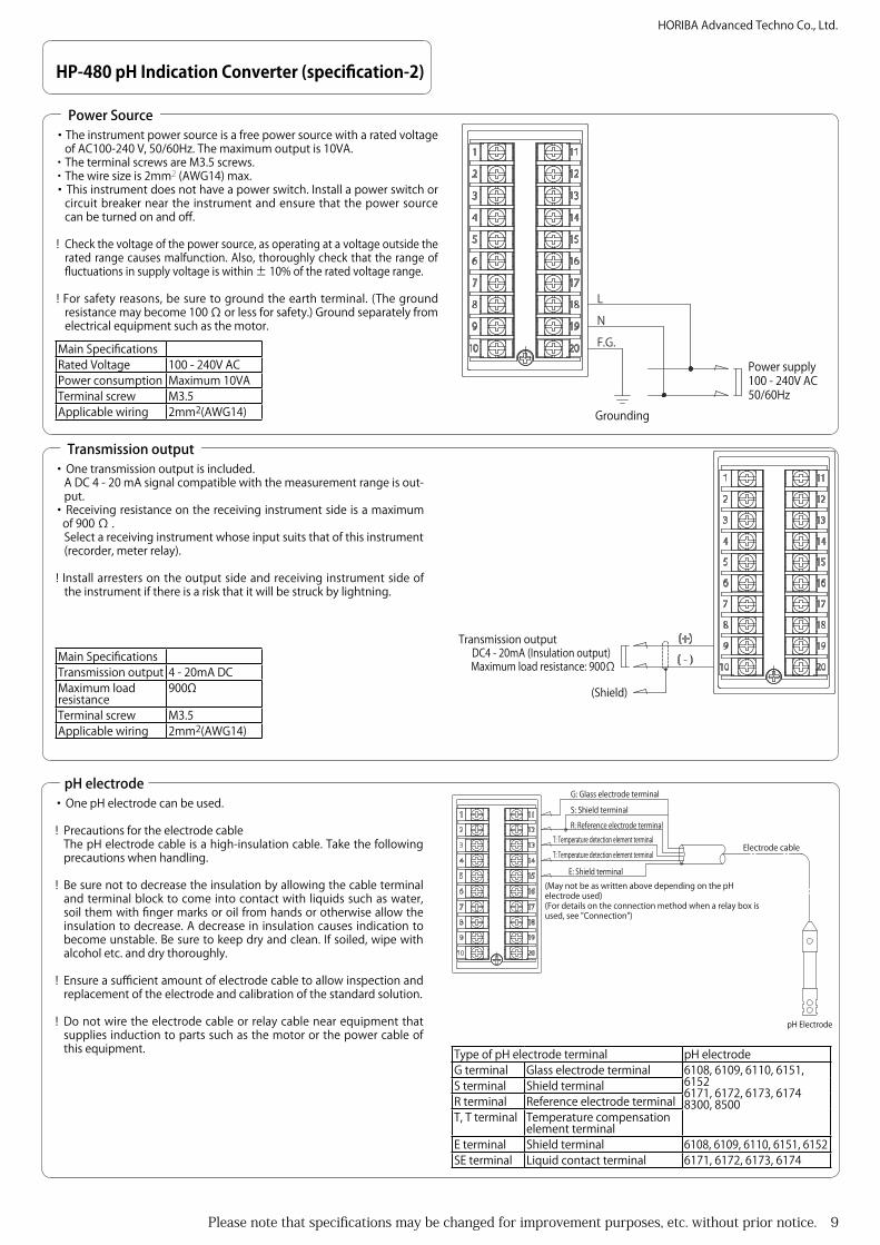
・Two contact outputs are included.・Can be selected from "Upper/lower limit operation (ON/OFF control)",
"Error warning (Error or FAIL)", "During maintenance (HOLD)" or "None". ・The contact capacity is less than AC 240V and 3A or DC 30V and 3 A.・The terminal screws are M3.5 screws.・The wire size is 2mm2 (AWG14) max.・Use a varistor or noise killer if noise occurs in the load.
! If connecting a load higher than the contact capacity or an inductive load (such as a motor or pump), be sure to connect the load through a power relay with a rating higher than that of the load.
! Take care when connecting a load, as the C-NC contact is shorted when the power source of this instrument is off.
Contact output
NO2C2
NO1C1
NC1
NC2
R1 Contact Output Capacity: 240V AC, 3A 30V DC, 3A (Load resistance)
R2 Contact Output Capacity: 240V AC, 3A 30V DC, 3A (Load resistance)
Main SpecificationsContact capacity Less than 240V AC, 3A or
less than 30V DC, 3AType of Contact Output
Upper/lower limit operation, error warning (Error or FAIL), during maintenance, none
Terminal screw M3.5Applicable wiring 2mm2(AWG14)
Types of contact (alarm) outputNo output No contact (alarm) output settings.Upper limit operation Performs ON/OFF control of the upper limit.Lower limit operation Performs ON/OFF control of the lower limit.Error warning
Error When an error code (E-23/E-24) is issued, the contact is output. However, a contact cannot be output as an error during calibration.
FAIL When an error code (E-21/E-22/E-90/E-91/E-92) is issued, the contact is output. However, a contact cannot be output as an error during calibration.
During maintenance (Hold) A contact is output when the mode is switched to maintenance mode (mode for configuring various settings such as measurement conditions and calibration).
pH 14
pH 0
ON
OFF
Control valueControl width
Time
1/2 control widthMeasuredvalue
Contact output
・Upper limit operation, lower limit operationThe control method, controlled values, type of control range (d.dif, S.dif), control range and delay time can be set.
Control method: Select whether to control by the upper limit operation or by lower limit operation.
Controlled values: Value that is the standard for operating the contact (alarm) output. Enter this value.
Type of control range: It is necessary to select the type of control range in order actually operate the contact (alarm) output. Select one of the two following types.
d.dif: Configures the settings centered on the controlled value so that the upper limit side and lower limit side are at the same width.
S.diF: Configures the settings based on the controlled value so that the upper limit side and lower limit side are at a different width.
Delay time: The operation and cancellation of the contact (alarm) output operation can be delayed for a fixed length of time. None of the operations are performed if the values that perform or cancel the operation fall below the controlled values during the delay time.
HP-480 pH Indication Converter (specification-3)
E.g.: When the control method is upper limit operation, controlled value is pH8, type of control range is d.dif and control range is 0.5
The contact (alarm) is made when the pH increases over pH8.25, and the contact (alarm) is broken when the pH decreases under pH7.75.

Please note that specifications may be changed for improvement purposes, etc. without prior notice. 11
HORIBA Advanced Techno Co., Ltd.
HP-480 pH Indication Converter (installation method -1)
45 +0.6 0
92+0
.8 0
Ensure that the space between the side panel cut is more than 70mm in the crosswise direction and more than 130mm in the longitudinal direction.
70
130
(Minimum)
(Minimum)
The installation method for this instrument is installation onto the control board (panel mount).The panel thickness is 1.0 - 9.0mm. Make a panel cut to the dimensions shown in the figure below.
Cut Dimensions, etc.
Groove (also on the base of the instrument)
Clip (also in the upper section of the inside of the mounting bracket)
Front panelPacking
Mounting bracket (after installation on the instrument)
Slide to front panel
Mounting bracket
Fit into the groove
Fit the panel between the front panel of the instrument unit and the mounting bracket (provided) and fix it in place.
Installation to the panel
Mounting bracket
Insertion section for flathead screwdriver
Disconnect the cables from the terminal block in advance.Remove one mounting bracket at a time, and remove the instrument unit from the panel.Insert a flathead screwdriver etc. in the gap between the mounting bracket and instrument unit on one side, and disconnect the clips.
Removal from the panel
Install following the conditions below to ensure the instrument is installed in stable conditions.・Well ventilated area・Ambient temperature is above -5°C and below 45°C・An area with no direct sunlight・An area where there is no direct high radiation heat・An area where the relative humidity of the surroundings is above 20% and less than 85%・An area where the instrument will not be splashed with water or chemicals・An area where there is little mechanical vibration・An area where maintenance and wiring work can be done・An area where there is no dust or corrosive gas・An area where there is little effect from electromagnetic fields・At an elevation less than 2000m・Where the range of fluctuations in supply voltage is within 10% of the rated voltage・An area that fulfills category II over-voltage (suitable for electrical equipment that supplies power from fixed equipment such as a panel board, etc.)
Installation environment

12 Please note that specifications may be changed for improvement purposes, etc. without prior notice.
HORIBA Advanced Techno Co., Ltd.
HP-480 pH Indication Converter (wiring method 1)
・The instrument power source is a free power source with a rated voltage of AC100-240 V, 50/60Hz. The maximum output is 10VA.
・The terminal screws are M3.5 screws.・The wire size is 2mm2 (AWG14) max.・This instrument does not have a power switch. Install a power switch
or circuit breaker near the instrument and ensure that the power source can be turned on and off.
! Check the voltage of the power source, as operating at a voltage outside the rated range causes malfunction. Also, thoroughly check that the range of fluctuations in supply voltage is within ± 10% of the rated voltage range.
! For safety reasons, be sure to ground the earth terminal. (The ground resistance may be 100 Ω or less for safety.) Ground separately from electrical equipment such as the motor.
! After completing wiring of the terminal block, be sure to install the terminal cover.
Power Source
F.G.NL
Power supply100 - 240V AC50/60Hz
Grounding
Main SpecificationsRated Voltage 100 - 240V ACPower consumption Maximum 10VATerminal screw M3.5Applicable wiring 2mm2(AWG14)
・One transmission output is included.A DC 4 - 20 mA signal compatible with the measurement range is output.
・ Receiving resistance on the receiving instrument side is a maximum of 900 Ω .Select a receiving instrument whose input suits that of this instrument (recorder, meter relay).
! Install arresters on the output side and receiving instrument side of the instrument if there is a risk that it will be struck by lightning.
Transmission output
Main SpecificationsTransmission output 4 - 20mA DCMaximum load resistance 900ΩTerminal screw M3.5Applicable wiring 2mm2(AWG14)
Transmission output DC4 - 20mA (Insulation output) Maximum load resistance: 900Ω
(Shield)
・Ground the shielded cable on the receiving instrument side.Receiver side
(+)
( - )
+
-Input from HP-480 →
Shield
Receiving instrument
Receiving resistance up to 900Ω
Earth terminal
・When serial connecting multiple receiving instruments as shown in the figure on the right.The total resistance for the connected receiving instrument is 900 Ω . (+)
( - )
+
-
+
-
Input from HP-480 →
Receiving instrument 1
Receiving resistance 1
Receiving resistance 2
Receiving instrument 2

Please note that specifications may be changed for improvement purposes, etc. without prior notice. 13
HORIBA Advanced Techno Co., Ltd.
HP-480 pH Indication Converter (wiring method 2)
・Two contact outputs are included.・Can be selected from "Upper/lower limit operation (ON/OFF control)",
"Error warning (Error or FAIL)", "During maintenance (HOLD)" or "None".
・The contact capacity is less than AC 240V and 3A or DC 30V and 3 A.・The terminal screws are M3.5 screws.・The wire size is 2mm2 (AWG14) max.・Use a varistor or noise killer if noise occurs in the load.
! If connecting a load higher than the contact capacity or an inductive load (such as a motor or pump), be sure to connect the load through a power relay with a rating higher than that of the load.
! Take care when connecting a load, as the C-NC contact is shorted when the power source of this instrument is off.
・Follow the diagram on the right and connect the contact outputs.
Contact output
NO2C2
NO1C1
NC1
NC2
R1 Contact Output Capacity: 240V AC, 3A 30V DC, 3A (Load resistance)
R2 Contact Output Capacity: 240V AC, 3A 30V DC, 3A (Load resistance)
Main SpecificationsContact capacity Less than 240V AC, 3A or
less than 30V DC, 3AType of Contact Output
Upper/lower limit operation, error warning (Error or FAIL), during maintenance, none
Terminal screw M3.5Applicable wiring 2mm2(AWG14)
・One pH electrode can be used.
! Precautions for the electrode cableThe pH electrode cable is a high-insulation cable. Take the following precautions when handling.
! Be sure not to decrease the insulation by allowing the cable terminal and terminal block to come into contact with liquids such as water, soil them with finger marks or oil from hands or otherwise allow the insulation to decrease. A decrease in insulation causes indication to become unstable. Be sure to keep dry and clean. If soiled, wipe with alcohol etc. and dry thoroughly.
! Ensure a sufficient amount of electrode cable to allow inspection and replacement of the electrode and calibration of the standard solution.
! Do not wire the electrode cable or relay cable near equipment that supplies induction to parts such as the motor or the power cable of this equipment.
Temperature compensated electrodeThis instrument can be used with the following 5 types of temperature compensated electrode.Resistance value at 25°C: 350 Ω , 500 Ω , 6.8 k Ω , 10 k ΩResistance value at 0°C: 1k ΩCheck the type of side temperature resistor used by the electrode, and set the temperature compensation on the instrument to an appropriate value.However, the initial temperature compensation setting for this instrument is 1kΩ.
Extending the electrode cableWhen extending the electrode cable, be sure to use the HORIBA・extension cable for electrode cables (C-5A)・Dedicated relay box (CT-25pH/TB-25pH).The maximum extension distance from the instrument unit to the electrode is 50m. Storing the dedicated relay cable in a conduit pipe is recommended to prevent issues such as static electricity caused by induction or vibration. In this case, run the wiring near the instrument through a flexible tube.
pH electrodeG: Glass electrode terminal
Electrode cable
(May not be as written above depending on the pH electrode used)(For details on the connection method when a relay box is used, see "Connection")
S: Shield terminalR: Reference electrode terminal
T: Temperature detection element terminalT: Temperature detection element terminal
E: Shield terminal
pH Electrode
Type of pH electrode terminal pH electrodeG terminal Glass electrode terminal 6108, 6109, 6110, 6151, 6152
6171, 6172, 6173, 61748300, 8500S terminal Shield terminal
R terminal Reference electrode terminal
T, T terminal Temperature detection element terminal
E terminal Shield terminal 6108, 6109, 6110, 6151, 6152SE terminal Liquid contact terminal 6171, 6172, 6173, 6174
14 Please note that specifications may be changed for improvement purposes, etc. without prior notice.
HORIBA Advanced Techno Co., Ltd.
HP-480 pH Indication Converter (wiring method 3)
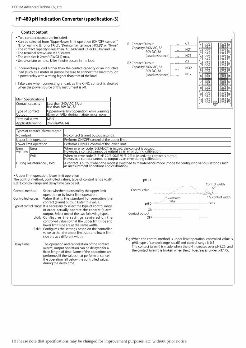
・The connection methods differ depend on the pH electrodes used.Connect as shown below.
pH electrode 2
G: Glass electrode terminalS: Shield terminalR: Reference electrode terminal
E: Outermost shield terminal
T: Temperature detection element terminalT: Temperature detection element terminal
《6108/6109/6110/6151/6152》pH Electrode
10 20
9
8
7
6
5
4
18
19
17
15
16
14
1
3
2
11
13
12
ET
ET
《CT-25pH/TB-25pH》
S
TR
S
TR
G G
C-5A-YT2-PSSRTT
E
G
《6108/6109/6110/6151/6152》
G: Glass electrode terminal
Relay box
Relay cableS: Shield terminalR: Reference electrode terminal
T: Temperature detection element terminalT: Temperature detection element terminal
E: Outermost shield terminal
G: Glass electrode terminalS: Shield terminalR: Reference electrode terminalT: Temperature detection element terminal
T: Temperature detection element terminal
E: Outermost shield terminal
pH Electrode
10 20
9
8
7
6
5
4
18
19
17
15
16
14
1
3
2
11
13
12
《6171/6172/6173/6174》
G: Glass electrode terminalS: Shield terminalR: Reference electrode terminalT: Temperature detection element terminalT: Temperature detection element terminalSE: Liquid contact terminal
pH Electrode
10 20
9
8
7
6
5
4
18
19
17
15
16
14
1
3
2
11
13
12
《6171/6172/6173/6174》
E/SET T
《CT-25pH/TB-25pH》
S
TR
S
TR
G G
C-5A-YT2-PSSRTT
E
G
E/SE
G: Glass electrode terminalS: Shield terminalR: Reference electrode terminal
T: Temperature detection element terminalT: Temperature detection element terminal
E: Outermost shield terminal
Relay box
Relay cableG: Glass electrode terminalS: Shield terminalR: Reference electrode terminalT: Temperature detection element terminalT: Temperature detection element terminalSE: Liquid contact terminal
pH Electrode
pH Electrode (6171, 6172, 6173, 6174) Connection Method
10 20
9
8
7
6
5
4
18
19
17
15
16
14
1
3
2
11
13
12
ET
ET
《CT-25pH/TB-25pH》
S
TR
S
TR
G G
C-5A-YT2-P RTT
E
G
《8300/8500》
G: Glass electrode terminalR: Reference electrode terminalT: Temperature detection element terminalT: Temperature detection element terminal
E: Outermost shield terminal
G: Glass electrode terminal
R: Reference electrode terminal
T: Temperature detection element terminalT: Temperature detection element terminal
E: Outermost shield terminal
Relay box
Relay cable
pH Electrode
G: Glass electrode terminalR: Reference electrode terminal
E: Outermost shield terminal
T: Temperature detection element terminalT: Temperature detection element terminal
《8300/8500》pH Electrode
pH Electrode (6108, 6109, 6110, 6151, 6152) Connection Method
pH Electrode (8300, 8500) Connection Method

Please note that specifications may be changed for improvement purposes, etc. without prior notice. 15
HORIBA Advanced Techno Co., Ltd.
HP-480 pH meter (Accessory)
・ Select the pH electrode according to the characteristics of the sample to be measured, installation location and other conditions, and whether various types of cleaners are used, etc.
・Electrical conductivity above 10mS/m (100 µS/cm) is required for pH measurement.
pH Electrode Overview
pH electrode
The following section contains specifications and other information on items other than the converter such as the pH electrode, holder and installation bracket.
pH electrode
Measurable range
Sample temperature (*1)
Sample pressure (*1) Cleaner Overview
6108 pH 0 - 14 -10 - 100 0-0.6 MPa Compatible Tough, difficult to break type.The tip section of the electrode is dome-shaped for easy cleaning.
6109 pH 0 - 14 -10 - 80 0 - 0.03 MPa CompatibleTough, difficult to break type.Uses a fixed sleeve (sample drop section). Ideal for use with highly viscous samples. (*2)
6110 pH 0 - 14 0 - 60 0 - 0.03 MPa Compatible
6151 pH 0 - 14 -10 - 60 0 - 0.2 MPa Not compatibleHydrofluoric acid resistant pH electrode.Life span of approximately 1 month in pH 3-4, 25 temperature and 1000ppm hydrofluoric acid. (*3)
6152 pH 0 - 14 -10 - 60 0 - 0.2 MPa Not compatible Alkali resistant pH electrode.3 months at pH 13, 60 temperature. (*3)
6171 pH 0 - 14 -10 - 60 0 - 0.03 MPa Not compatibleHydrofluoric acid resistant pH electrode.pH electrode, reference electrode has a replaceable tip.Approximately 1 month in pH 3-4, 25 temperature and 1000ppm hydrofluoric acid. (*3)
6172 pH 0 - 14 -10 - 60 0 - 0.03 MPa Not compatibleAlkali resistant pH electrode.pH electrode, reference electrode has a replaceable tip.3 months at pH 13, 60 temperature. (*3)
6173 pH 0 - 14 -10 - 60 0 - 0.03 MPa Not compatibleOil resistant pH electrode.pH electrode, reference electrode has a replaceable tip.Compatible with oil refining processes or samples for boiler circulating water that contain oil. (*4)
6174 pH 0 - 14 -10 - 100 0 - 0.03 MPa Not compatible pH electrode, reference electrode has a replaceable tip.
8300 pH 0 - 14 0 - 50 0 - 0.2 MPa Not compatible KCI no-supply type immersion pH electrode.8500 (*5) pH 0 - 14 0 - 50 0 - 0.2 MPa Not compatible KCI no-supply type immersion pH electrode.
*1: Differs depending on the specifications of the holder, etc. *2: Does not necessarily support all high viscosity samples. *3: The indicated life spans are just a guide. They are not guaranteed values.*4: Does not necessarily support all oils and samples containing oil.*5: pH electrode for vertical floating type holders and inclined floating type holders.

16 Please note that specifications may be changed for improvement purposes, etc. without prior notice.
HORIBA Advanced Techno Co., Ltd.
Accessories (pH electrode 1)
pH electrode
Model 6108-50BMeasurement method Glass electrode methodMeasurable range pH 0 -14Sample water conditions
Temperature range
-10 - 100 (no freezing)
Pressure 0 - 0.6 MPaReference electrode
Sample drop section
Multi-pore ceramic
Internal liquid 3.3 mol KCI (refilling type)Cable length Standard 5m (+5%)Combination Immersion
type holderCH-101/CH-101-P/CH-101-PF
pH flow chamber
CF-251/CF-251-T/CF-301/CF-401
Immersion type cleaner
UCH-101, UCH-111
pH flow cleaner
UCF-301, UCH-311
Model 6109-50BMeasurement method Glass electrode methodMeasurable range pH 0 -14Sample water conditions
Temperature range
-10 - 80 (no freezing)
Pressure 0 - 0.03 MPaReference electrode
Sample drop section
Glass sleeve
Internal liquid 3.3 mol KCI (refilling type)Cable length Standard 5m (+5%)Combination Immersion
type holderCH-101/CH-101-P/CH-101-PF
pH flow chamber
CF-251/CF-251-T
Immersion type cleaner
UCH-101, UCH-111
pH flow cleaner
None
Model 6110-50BMeasurement method Glass electrode methodMeasurable range pH 0 -14Sample water conditions
Temperature range
0 - 60 (no freezing)
Pressure 0 - 0.03 MPaReference electrode
Sample drop section
Multi-pore ceramic
Internal liquid 3.3 mol KCI (refilling type)Cable length Standard 5m (+5%)Combination Immersion type
holderCH-101/CH-101-P/CH-101-PF
pH flow chamber CF-251/CF-251-TImmersion type cleaner
UCH-101, UCH-111
pH flow cleaner None
pH electrode (6108)
pH electrode (6110)
pH electrode (6109)
Please note that specifications may be changed for improvement purposes, etc. without prior notice. 17
HORIBA Advanced Techno Co., Ltd.
Accessories (pH electrode 2)
pH electrode
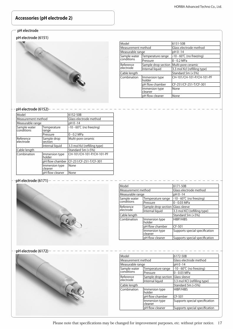
pH electrode (6151)
Model 6152-50BMeasurement method Glass electrode methodMeasurable range pH 0 -14Sample water conditions
Temperature range
-10 - 60 (no freezing)
Pressure 0 - 0.2 MPaReference electrode
Sample drop section
Multi-pore ceramic
Internal liquid 3.3 mol Kcl (refilling type)Cable length Standard 5m (+5%)Combination Immersion type
holderCH-101/CH-101-P/CH-101-PF
pH flow chamber CF-251/CF-251-T/CF-301Immersion type cleaner
None
pH flow cleaner None
Model 6171-50BMeasurement method Glass electrode methodMeasurable range pH 0 -14Sample water conditions
Temperature range -10 - 60 (no freezing)Pressure 0 - 0.03 MPa
Reference electrode
Sample drop section Glass sleeveInternal liquid 3.3 mol KCI (refilling type)
Cable length Standard 5m (+5%)Combination Immersion type
holderHIBP/HIBS
pH flow chamber CF-501Immersion type cleaner
Supports special specification
pH flow cleaner Supports special specification
Model 6172-50BMeasurement method Glass electrode methodMeasurable range pH 0 -14Sample water conditions
Temperature range -10 - 60 (no freezing)Pressure 0 - 0.03 MPa
Reference electrode
Sample drop section Glass sleeveInternal liquid 3.3 mol KCI (refilling type)
Cable length Standard 5m (+5%)Combination Immersion type
holderHIBP/HIBS
pH flow chamber CF-501Immersion type cleaner
Supports special specification
pH flow cleaner Supports special specification
Model 6151-50BMeasurement method Glass electrode methodMeasurable range pH 0 -14Sample water conditions
Temperature range -10 - 60 (no freezing)Pressure 0 - 0.2 MPa
Reference electrode
Sample drop section Multi-pore ceramicInternal liquid 3.3 mol Kcl (refilling type)
Cable length Standard 5m (+5%)Combination Immersion type
holderCH-101/CH-101-P/CH-101-PF
pH flow chamber CF-251/CF-251-T/CF-301Immersion type cleaner
None
pH flow cleaner None
pH electrode (6152)
pH electrode (6172)
pH electrode (6171)
18 Please note that specifications may be changed for improvement purposes, etc. without prior notice.
HORIBA Advanced Techno Co., Ltd.
Model 6174-50BMeasurement method Glass electrode methodMeasurable range pH 0 -14Sample water conditions
Temperature range -10 - 100 (no freezing)Pressure 0 - 0.03 MPa
Reference electrode Sample drop section Glass sleeveInternal liquid 3.3 mol KCI (refilling type)
Cable length Standard 5m (+5%)Combination Immersion type holder HIBP/HIBS
pH flow chamber CF-501Immersion type cleaner NonepH flow cleaner None
Model 6173-50BMeasurement method Glass electrode methodMeasurable range pH 0 -14Sample water conditions
Temperature range -10 - 60 (no freezing)Pressure 0 - 0.03 MPa
Reference electrode
Sample drop section Glass sleeveInternal liquid 3.3 mol KCI (refilling type)
Cable length Standard 5m (+5%)Combination Immersion type holder HIBP/HIBS
pH flow chamber CF-501Immersion type cleaner NonepH flow cleaner None
Accessories (pH electrode 2)
pH electrode
pH electrode (6173) pH electrode (6174)
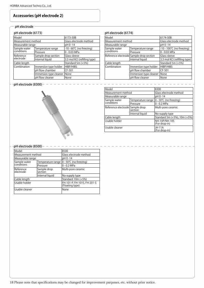
Model 8300Measurement method Glass electrode methodMeasurable range pH 0 -14Sample water conditions
Temperature range 0 - 50 (no freezing)Pressure 0 - 0.2 MPa
Reference electrode Sample drop section
Multi-pore ceramic
Internal liquid No-supply typeCable length Standard 5m (+5%), 10m (+5%)Usable holder NH-10P/NH-10S
(For drop-in)Usable cleaner JH-11A
(For drop-in)
Model 8500Measurement method Glass electrode methodMeasurable range pH 0 -14Sample water conditions
Temperature range 0 - 50 (no freezing)Pressure 0 - 0.2 MPa
Reference electrode
Sample drop section
Multi-pore ceramic
Internal liquid No-supply typeCable length Standard 10m (+5%)Usable holder FH-101-P, FH-101S, FH-201-S
(Floating type)Usable cleaner None
pH electrode (8500)
pH electrode (8300)

Please note that specifications may be changed for improvement purposes, etc. without prior notice. 19
HORIBA Advanced Techno Co., Ltd.
Accessories (immersion type holder)
Immersion type holder
Immersion type holder (CH-101 series)Model CH-101 CH-101P CH-101PFHolder material PP PVC PVDFConditions Temperature -5 - 80 -5 - 50 -5 - 100
Pressure Atmospheric pressureFlow velocity Less than 2m/sec
Holder length (m) 0.5, 1.0, 1.5, 2.0, 2.5, 3.0Combination pH electrode 6108, 6109,
61106108, 6109, 6110, 6151, 6152
6108
(There are cases when combinations cannot be made based on the sample characteristics and usage conditions, etc.)
Mounting brackets
BA-1A, BA-1S, MB-10(The combination above is limited to when an immersion type holder up to 1.5m is used. When using an immersion type holder of 2m or more, use a combination of the support type (SP-60) + mounting bracket (MH-65).)
LooseFlange
FK-1, FK-1P, FK-1S(The combination above is limited to when an immersion type holder up to 1.5m is used.)
-
Cleaner UCH-101(There are cases that cannot be used due to the sample characteristics, etc.)
Immersion type holder (HIB series)Model HIBP HIBSHolder material PP SUS316Temperature -5 - 80 -5 - 100Pressure Atmospheric pressureFlow velocity Less than 2m/secHolder length (m) 0.5, 1.0, 1.5, 2.0, 2.5, 3.0Combination pH
electrode6171, 6172, 6173, 6174(There are cases where this combination cannot be used due to the sample characteristics, etc.)
Mounting brackets
MB-10(The combination above is limited to when an immersion type holder up to 1.5m is used.When using an HIBP immersion type holder of 2m or more, use a combination of the support type (SP-60) + mounting bracket (MH-65).)Contact HORIBA to use a HIBP immersion type holder of 2m or more. Special specifications are required.)
LooseFlange
- RFS1(The combination above is limited to when an immersion type holder up to 1.5m is used.)
Cleaner Supports special specification

20 Please note that specifications may be changed for improvement purposes, etc. without prior notice.
HORIBA Advanced Techno Co., Ltd.
Accessories (pH flow chamber)
pH flow chamber
pH flow chamber (CF-251 series)Model CF-251 CF-251P CF-251SHolder material PP PVC SUS316Ambient temperature -5 - 60 -5 - 50 -5 - 60Conditions Temperature -5 - 80 -5 - 50 -5 - 100
(No freezing)Pressure Atmospheric pressureFlow rate 0.3-10L/min
Connector diameter JIS 10K 25A FF flangeCombination pH electrode 6108, 6109
61106108, 61096110
6108
(There are cases that cannot be used due to the sample characteristics, etc.)
Model CF-251-T CF-251P-T CF-251S-THolder material PP PVC SUS316Ambient temperature -5 - 60 -5 - 50 -5 - 60Conditions Temperature -5 - 80 -5 - 50 -5 - 100
(No freezing)Pressure Atmospheric pressureFlow rate 0.3-10L/min
Connector diameter JIS 10K 25A FF flangeCombination pH electrode 6108, 6109
61106108, 61096110
6108
(There are cases that cannot be used due to the sample characteristics, etc.)
pH flow chamber (CF-251-T series)
Model CF-301 CF-301P CF-301SpH flow chamber material PP PVC SUS316Ambient temperature -5 - 60 -5 - 50 -5 - 60Conditions Temperature -5 - 80 -5 - 50 -5 - 100
(No freezing)Pressure -5 - 40
: 0.30MPa 40 - 60 : 0.22MPa 60 - 80 : 0.15MPa
-5 - 40 : 0.30MPa 40 - 50 : 0.15MPa
-5 - 40 : 0.30MPa 40 - 60 : 0.25MPa 60 - 80 : 0.20MPa 80 - 100 : 0.15MPa
Flow rate 0.3-10L/minMeasurement liquid connection diameter
JIS 10K 25A FF flange
Pressurized opening in holder Rc 1/8Combination pH electrode 6108
pH flow chamber (CF-301 series)
pH flow chamber (CF-401S)Model CF-401SpH flow chamber material SUS316Ambient temperature -5 - 60Conditions Temperature -5 - 100
(No freezing)Pressure -5 - 40 : 0.60MPa
40 - 60 : 0.46MPa 60 - 90 : 0.26MPa 90 - 100 : 0.20MPa
Flow rate 0.5-10L/minConnector diameter JIS 10K 25A FF flangePressurized opening in holder Rc 1/8Combination pH electrode 6108
Model CF-501 CF-501P CF-501SHolder material PP PVC SUS316Ambient temperature -5 - 60 -5 - 50 -5 - 60Conditions Temperature -5 - 80 -5 - 60 -5 - 100
(No freezing)Pressure Atmospheric pressureFlow rate 0.3-10L/min
Measurement liquid connection diameter
JIS 10K 25A FF flange
Combination pH electrode 6174 6171, 61726173, 6174
6174
(There are cases that cannot be used due to the sample characteristics, etc.)
pH flow chamber (CF-501 series)

Please note that specifications may be changed for improvement purposes, etc. without prior notice. 21
HORIBA Advanced Techno Co., Ltd.
Accessories (Mounting brackets, support pipe, loose flange)
Mounting brackets
Mounting brackets (BA-1A)
Mounting brackets (BA-1S) Mounting brackets (MB-10)
Mounting brackets (MH-65) Mounting brackets (MH-100)
Model BA-1AMaterial ABS resinInstallation method Anchor installationCombination Immersion
holderCH-101/CH-101-P/CH-101-PF(An immersion type holder with a holder length of up to 1.5m can be used.)
Model BA-1SMaterial SUS304Installation method Anchor installationCombination Immersion
holderCH-101/CH-101-P/CH-101-PF(An immersion type holder with a holder length of up to 1.5m can be used.)
Model MB-10Material SUS304, SCS13Installation method Pole Mounting (50A) Combination Immersion
holderCH-101/CH-101-P/CH-101-PFHIBP/HIBS(An immersion type holder with a holder length of up to 1.5m can be used.)
Model MH-65Material SUS304Installation method Pole Mounting (50A)
Use when securing a support pipe (SP-60) or cleaner to the pole stand.
Combination Immersion holder
CH-101/CH-101-P/CH-101-PFHIBP/HIBS(Use together with an immersion holder that has a holder length greater than 2m and support pipe (SP-60).)
Cleaner UCH-101, UCH-111
Model MH-100Material SUS304Installation method Pole Mounting (50A)
Use when securing to the pole stand.Combination Drop-in
holderNH-10P, HN-100S
Support pipe
Support pipe (SP-60)Model SP-60Material SUS304, PVCCompatible holder lengths (m) 1.0, 1.5, 2.0, 2.5, 3.0Combination Immersion type
holderCH-101, CH-101P, CH-101PFHIBP
Mounting brackets MH-65If the flow speed is high even with a holder length less than 1.5m, a support pipe may be required.
Loose flange
Loose flange (FK-1 series)
Loose flange (RFS1)
Model FK-1 FK-1P FK-1SMaterial Flange PP PVC SUS316
Nuts PP PVC SUS304Washer PP PVC PPPacking FKM FKM FKM
Flange standards JIS 10K 50A FF, etc.Combination CH-101, CH-101-P
There are cases that cannot be used due to the sample characteristics.
Use with a holder length less than 1.5m. If the flow speed is high even with a holder length less than 1.5m, it may not be usable. In that case, it is recommended that a support pipe is used.
Model RFS1Material SUS316Flange standards JIS 10K 50A FF, etc.Combination HIBP/HIBS
There are cases that cannot be used due to the sample characteristics.
Use with a holder length less than 1.5m. If the flow speed is high even with a holder length less than 1.5m, it may not be usable. In that case, it is recommended that a support pipe is used.

22 Please note that specifications may be changed for improvement purposes, etc. without prior notice.
HORIBA Advanced Techno Co., Ltd.
Accessories (Pole stand, relay box, Relay cable, etc.)
Pole stand
Pole stand (PS-50)Model PS-60Material SUS316
Relay box
Relay box (CT-25pH)Model CT-25pHMaterial ABSIt has a rainproof structure, but should not be used in humid conditions.
Relay cable
Relay cable, etc. (C-5A)Model C-5AMaximum extension
Up to 50mHowever, this includes the pH electrode lead cable.
Terminal processed cable cordC-5A-Y-T2-P For pH electrode 8300, 8500C-5A-Y-T2-PS For pH electrode 6108, 6109, 6110, 6151, 6152C-5A-Y-T2-PSE For pH electrode 6171, 6172, 6173, 6174
Relay box (TB-25pH)Model TB-25pHMaterial PPOInstallation Conditions Temperature -5 - 40 (no freezing)
Splash-proof construction. Use this relay box in humid conditions.However, the desiccant inside the relay box needs to be replaced periodically (between 6 months to 1 year).

Please note that specifications may be changed for improvement purposes, etc. without prior notice. 23
HORIBA Advanced Techno Co., Ltd.
Accessories (cleaner-1)
Type Target Ultrasound cleanerSlime Food, paper, pulp, algae Microbes Bacteria (activated sludge), slag Oil Tar, heavy oil ×
Light oil Fatty acids, amines ×
Suspended solids
Earth and sand Fine metal powder Clay, lime
Scale Sediment clumps, neutralizing processing, calcium carbonate
Cleaners are comparatively effective on the types of sample characteristics described above. However, the effectiveness of cleaning differs according to various conditions and cannot be guaranteed. : Good : Possible × : Not possible
Comparison of cleaning effects according to sample characteristics
Depending on the characteristics of the sample to be measured, installing a cleaner may increase the maintenance frequency of electrodes.An ultrasound cleaner can be installed to this instrument. Also, cleaners whose installation methods can be used with immersion type and flow type electrodes are available.
Cleaner
Model UCH-101 (Integrated ultrasound oscillator)
Power source voltage 100 - 240V AC, 50/60HzAllowable voltage fluctuation range
90-100% of power source voltage
Power consumption 10 VACleaning method Continuous ultrasound emission methodControl method Burst method through oscillation timing
controlAmbient temperature -5 - 50Ambient humidity 5-90% relative humidity (no
condensation)Measured liquid temperature (*1)
-5 - 80 (no freezing)
Flow velocity of measured liquid
Less than 2m/sec
Measured liquid pressure Atmospheric pressureUsable holder length 0.5, 1.0, 1.5, 2.0, 2.5, 3.0Mass Approx. 4.0kg (if immersion holder length
is 1m)Combined pH electrodes (*1) 6108, 6109, 6110Combined immersion holder (*1)
CH-101, CH-101P, CH-101PF
Installable mounting bracket MH-65*1: The usage temperature range varies depending on the combined pH electrode and immersion holder.
Check the specified temperatures of each product.
Immersion type ultrasound cleaner (UCH-111)Model UCH-111 (Separate installation type ultrasound oscillator)Power source voltage 100 - 240V AC, 50/60HzAllowable voltage fluctuation range 90-100% of power source voltagePower consumption 10 VACleaning method Continuous ultrasound emission methodControl method Burst method through oscillation timing controlAmbient temperature -5 - 50Ambient humidity 5-90% relative humidity (no condensation)Measured liquid temperature (*1) -5 - 80 (no freezing)Flow velocity of measured liquid Less than 2m/secMeasured liquid pressure Atmospheric pressureUsable holder length 0.5, 1.0, 1.5, 2.0, 2.5, 3.0Mass Approx. 2.5kg (if immersion holder length is 1m)Ultrasound oscillator US-2Combined pH electrodes (*1) 6108, 6109, 6110Combined immersion holder (*1) CH-101, CH-101P, CH-101PFInstallable mounting bracket MH-65*1: The usage temperature range varies depending on the combined pH electrode and immersion holder.
Check the specified temperatures of each product.
Immersion type ultrasound cleaner
Immersion type ultrasound cleaner (UCH-101)

24 Please note that specifications may be changed for improvement purposes, etc. without prior notice.
HORIBA Advanced Techno Co., Ltd.
Accessories (cleaner-2)
Flow type ultrasound cleaner (UCF-311)
Flow type ultrasound cleaner
Flow type ultrasound cleaner (UCF-301)Model UCF-301 (Integrated ultrasound oscillator)Ambient temperature -5 - 50Ambient humidity 5-90% relative humidity (no condensation)Conditions Temperature
(*1)-5 - 80 (no freezing)
Pressure -5 - 40 : 0.30MPa 40 - 60 : 0.22MPa 60 - 80 : 0.15MPa
Flow rate 0.3-10L/minPower source voltage 100 - 240V AC, 50/60HzPower consumption 10 VACleaning method Continuous ultrasound emission methodControl method Burst method through oscillation timing
controlMeasurement liquid connector diameter
JIS 10K 25A FF flange
Pressurized opening in holder
Rc1/8
Mass Approx. 7.0kgCombined pH electrodes 6108*1: The usage temperature range varies depending on the combined electrode and holder. Check the specified temperatures of each product.
Model UCF-311 (Separate installation type ultrasound oscillator)Ambient temperature -5 - 50Ambient humidity 5-90% relative humidity (no condensation)Conditions Temperature (*1) -5 - 80 (no freezing)
Pressure -5 - 40 : 0.30MPa 40 - 60 : 0.22MPa 60 - 80 : 0.15MPa
Flow rate 0.3-10L/minPower source voltage 100 - 240V AC, 50/60HzPower consumption 10 VACleaning method Continuous ultrasound emission methodControl method Burst method through oscillation timing controlMeasurement liquid connector diameter JIS 10K 25A FF flangePressurized opening in holder Rc1/8Mass Oscillator: Approx. 2.0kg
Cleaning unit: Approx. 3.0kgUltrasound oscillator US-2Combined pH electrodes 6108*1: The usage temperature range varies depending on the combined electrode and holder. Check the specified temperatures of each product.
Ultrasound oscillator (US-2)Model US-2Ambient temperature -5 - 50Ambient humidity 5-90% relative humidity (no condensation)Oscillation frequency Approx. 70 kHz Power source voltage AC100-240V 50/60HzAllowable voltage fluctuation range
90-100% of power source voltage
Power consumption 10 VACleaning method Continuous ultrasound emission methodControl method Burst method through oscillation timing
controlMass Approx. 2.0kgProtection class IP54 (IEC60529, JIS C0920) (Category 2)Material AC4CSurface Epoxy glue degeneration melamine resin
painting (Mansell 10PB5/1)
Flow type ultrasound cleaner
Please note that specifications may be changed for improvement purposes, etc. without prior notice. 25
HORIBA Advanced Techno Co., Ltd.
HP-480 pH meter accessory (installation method -1)
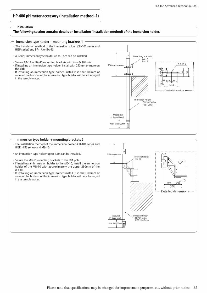
60
9030
58.5
135.5
(36)
2-∅10.5
(72)
250mm or more
Measured liquid level
More than 100mm
Mounting brackets BA-1A BA-1S
Immersion holder CH-101 Series HIBP Series
Detailed dimensions
・The installation method of the immersion holder (CH-101 series and HIBP series) and BA-1A or BA-1S.
・A (resin) immersion type holder up to 1.5m can be installed.
・Secure BA-1A or BA-1S mounting brackets with two Φ 10 bolts.・If installing an immersion type holder, install with 250mm or more on
the slab.・If installing an immersion type holder, install it so that 100mm or
more of the bottom of the immersion type holder will be submerged in the sample water.
Immersion type holder + mounting brackets 1
The following section contains details on installation (installation method) of the immersion holder.Installation
More than 100mm
Measured liquid level
Mounting brackets MB-10
Immersion holder CH-101 Series HIBP, HIBS Series
(50)(138)
(88)
250mm or more
Detailed dimensions
・The installation method of the immersion holder (CH-101 series and HIBP, HIBS series) and MB-10.
・An immersion type holder up to 1.5m can be installed.
・Secure the MB-10 mounting brackets to the 50A pole.・If installing an immersion holder to the MB-10, install the immersion
holder of the MB-10 with approximately the upper 250mm of the U-bolt.
・If installing an immersion type holder, install it so that 100mm or more of the bottom of the immersion type holder will be submerged in the sample water.
Immersion type holder + mounting brackets 2

26 Please note that specifications may be changed for improvement purposes, etc. without prior notice.
HORIBA Advanced Techno Co., Ltd.
HP-480 pH meter accessory (installation method -2)
Maintenance space to allow removal of the immersion holder is required
Measured liquid level
More than 100mm
Immersion holder CH-101 Series HIBP Series
・The installation method of the immersion holder (CH-101 series and HIBP series) and FK-1 series.
・A (resin) immersion type holder up to 1.5m can be installed.
・ The standard size of the FK-1 series is JIS 10K 50A FF. If installing a special specification loose flange, check the size before installation.
・ If installing an immersion type holder to the FK-1 series, install so that the holder is more than 200mm from the upper part of the loose flange cap nut.
・ If installing an immersion type holder, install it so that 100mm or more of the bottom of the immersion type holder will be submerged in the sample water.
Immersion holder + loose flange 1
Maintenance space to allow removal of the immersion holder is required
Measured liquid level
More than 200mm
Immersion holder HIBS series
・The installation method of the immersion holder (HIBP series) and RFS1 series.
・An immersion type holder up to 1.5m can be installed.
・The standard size of the RFS1 is 10K 50A FF. If installing a special specification loose flange, check the size before installation.
・If installing an immersion type holder to the RFS1, install so that the holder is more than 200mm from the upper part of the loose flange cap nut.
・If installing an immersion type holder, install it so that 200mm or more of the bottom of the immersion type holder will be submerged in the sample water.
Immersion holder + loose flange 2

Please note that specifications may be changed for improvement purposes, etc. without prior notice. 27
HORIBA Advanced Techno Co., Ltd.
HP-480 pH meter accessory (installation method -3)
Pole stand: PS-50
Mounting brackets: MH-65
Support pipe: SP-60
Measured liquid level
More than 100mm
Immersion holder CH-101 Series HIBP Series
・The installation method of the immersion holder (CH-101 series and HIBP series) support pile (SP-60) and mounting bracket (MH-65).
・This combination is used when the immersion holder to be installed is over 2m. (When using an immersion holder that is less than 2m, it is necessary to install in this combination if the flow speed is fast.)
・If installing an immersion type holder, install it so that 100mm or more of the bottom of the immersion type holder will be submerged in the sample water.
Immersion holder + support pipe + mounting brackets

28 Please note that specifications may be changed for improvement purposes, etc. without prior notice.
HORIBA Advanced Techno Co., Ltd.
Maintenance space: 150mm or more
pH flow chamber: CF-251 series: CF-251-T series
Do not install the output pipe vertically.
Open-air
Open-air
Main line
Sampling line
・Installation (plumbing) method for the pH flow chamber (CF-251 series and CF-251-T series).
・To install the pH flow chamber, install a sampling line to the main line and mount so that the measured liquid flows in from the bottom of the pH flow chamber and out from the side.
・Make the output plumbing from the pH flow chamber as short as possible, and always expose it to open-air once.
・Do not install the output pipe vertically. Otherwise, back pressure occurs inside the pH flow chamber, reverse leak of the measured liquid occurs in the electrode, and measurement cannot be made accurately. (Electrodes in which reverse leak has occurred can no longer be used.)
・Always install a valve on the inflow side. See [Fig.1].・If the flow rate of the measured liquid is too fast, capitation, etc. may
occur, or changes in the indication values may occur due to increased pressure in the electrode supply route due to the flow rate. However, if the flow rate is too low, delays occur in the response rate of the indication values. In this case, adjust the flow rate in accordance with the measurement fluid.
・In cases where there is a lot of floating matter in the measured liquid, attach a strainer to the inflow side of the holder. See [Fig.2].
HP-480 pH meter ph flow chamber(installation method -4)
pH flow chamber 1
Fig.1
Maintenance space: 150mm or more
pH flow chamber: CF-251 series: CF-251-T series
Do not install the output pipe vertically.
Main line
Strainer
Sampling line
Open-air
Open-air
Fig.2
Install following the conditions below to ensure the instrument is installed in stable conditions.・Install in an area where operations such as maintenance can be performed easily.・Allow maintenance space over the holder cap, upper section of the KCI tank lid and upper section of the pressurized holder. Also, allow space to
enable removal of the electrode cable for maintenance, etc. ・Do not install in locations where there is substantial vibration or a lot of dust. ・Install so that the measured liquid does not drain away from the pH flow chamber leaving the electrode exposed to the air even if the flow of
measured liquid stops.・Do not install in locations where corrosive liquid may be splashed or where corrosive gas may be in the atmosphere.・Avoid installing in areas where the surface or ambient temperature will exceed 50 , such as beside heating elements.・If air bubbles, slurry or solid matter that may damage the electrodes are contained in the measured liquid, remove these in advance. ・ Do not mount the pH flow chamber on the main line. Always install a sampling line and mount on the sampling line (otherwise maintenance will not
be possible without stopping the main line).
Installation Environment (common for pH flow chambers)

Please note that specifications may be changed for improvement purposes, etc. without prior notice. 29
HORIBA Advanced Techno Co., Ltd.
Bypass line
Maintenance space150mm or more
Bypass line
Main line
・Installation (plumbing) method for the pH flow chamber CF-301.
・To install the pH flow chamber, install a bypass line to the main line and mount so that the measured liquid flows in from the bottom of the pH flow chamber and out from the side.
・Always install valves on the inflow and outflow sides. If the flow rate of the measured liquid is too fast, capitation, etc. may occur, or changes in the indication values may occur due to increased pressure in the electrode supply route due to the flow rate. However, if the flow rate is too low, delays occur in the response rate of the indication values. In this case, adjust the flow rate in accordance with the measurement fluid.
・In cases where there is a lot of floating matter in the measured liquid, attach a strainer to the inflow side of the holder. See [Fig.3]
HP-480 pH meter ph flow chamber (installation method -5)
pH flow chamber 2
Bypass line
Bypass lineStrainer
Maintenance space150mm or more
Main lineBypass line
Bypass line
Maintenance space150mm or more
Main line
Fig.1
Fig.2 Fig.3
Pressurization Method・There are two types of pressurization.
Manual pressurization ・Prepare a union joint (screw diameter: Rc1/8) and air pump. (Available
from HORIBA as an option)・Pressurize to 0.03 - 0.05 MPa above the sample pressure. However,
do not pressurize above the specifications. (See temperature and pressure relationship chart)
・Check the pressure regularly. Air pressure reduces over time.
When using instrumentation air・To pressurize using instrumentation air, install a union joint. See [Fig.4]・Remove the pressurized holder for maintenance. Construct using a
flexible pipe.・Install a regulator (with filter) near the pressurized holder, and
connect between the pressurized holder with a tube ( Φ 4 × Φ 6). See [Fig.4]
- Caution - ・The Rc1/8 screw of the pressurized opening is made of a resin base,
and overtightening will damage the screw section. ・The pressurized holder may be removed for maintenance work, etc.
therefore be sure to allow space around the air pipes when fixing in place.
150 or more maintenance space
Screw diameter: Rc1/8
Pressurizing unit (optional) When using an air pumpTube coupling (optional) When using instrumentation air
Regulator (with filter)
Stop valve
Coil tube (optional) Φ4×Φ6
-50 10 25 40 55 10070 85
0.15
0.05
0.1
0.2
0.25
0.3
0.35
Relationship Between Temperature and Pressure
Measured liquid temperature ()
Usage range
Meas
ured
liquid
pres
sure
(MPa
)
May not be as indicated in the table on the left depending on the material of the selected holder. Check the specifications.
Fig.4

30 Please note that specifications may be changed for improvement purposes, etc. without prior notice.
HORIBA Advanced Techno Co., Ltd.
Bypass line
Bypass line
Bypass line
Either
Maintenance space200mm or more
Main line
・Installation (plumbing) method for the pH flow chamber CF-401.
・Install in an area where operations such as maintenance can be performed easily.
・Leave at least 20cm of maintenance space above the pressurized holder. Also, allow space to enable removal of the electrode cable for maintenance, etc.
・Do not install in locations where there is substantial vibration or a lot of dust.・Install so that the measured liquid does not drain away from the pH
flow chamber leaving the electrode exposed to the air even if the flow of measured liquid stops.
・Do not install in locations where corrosive liquid may be splashed or where corrosive gas may be in the atmosphere.
・Avoid installing in areas where the surface or ambient temperature will exceed 50 , such as beside heating elements.
HP-480 pH meter ph flow chamber (installation method -6)
pH flow chamber 3
Bypass lineStrainer
Bypass line
Maintenance space200mm or more
Main line
Fig.1 Fig.2
Pressurization Method・There are two types of pressurization.
Manual pressurization・Prepare a union joint (screw diameter: Rc1/8) and air pump. (Available
from HORIBA as an option)・Pressurize to 0.03 - 0.05 MPa above the sample pressure. However,
do not pressurize above the specifications. (See temperature and pressure relationship chart)
・Check the pressure regularly. Air pressure reduces over time.
When using instrumentation air・To pressurize using instrumentation air, install a union joint. See [Fig.4]・Remove the pressurized holder for maintenance. Construct using a
flexible pipe.・Install a regulator (with filter) near the pressurized holder, and
connect between the pressurized holder with a tube ( Φ 4 × Φ 6). See [Fig.3]
- Caution -・The Rc1/8 screw of the pressurized opening is made of a resin base,
and overtightening will damage the screw section.・The pressurized holder may be removed for maintenance work, etc.
therefore be sure to allow space around the air pipes when fixing in place.
150 or more maintenance space
Screw diameter: Rc1/8
Pressurizing unit (optional) When using an air pump
Tube coupling (optional) When using instrumentation air
Regulator (with filter)
Stop valve
Coil tube (optional) Φ4×Φ6
Relationship Between Temperature and Pressure
Usage range
Measured liquid temperature ()
Meas
ured
liquid
pres
sure
(MPa
)
0.4
0.3
0.2
-50
0.1
10 25 40 55 70 10085
0.7
0.5
0.6
Fig.3
・If air bubbles, slurry or solid matter that may damage the electrodes are contained in the measured liquid, remove these in advance.
・Do not mount the pH flow chamber on the main line. Always install a bypass line before installation. (Otherwise maintenance cannot be performed without stopping the main line.) To install the pH flow chamber, install a bypass line to the main line and mount so that the measured liquid flows in from the bottom of the pH flow chamber and out from the side. Always install valves on the inflow and outflow sides. See [Fig.1]
・If the flow rate of the measured liquid is too fast, capitation, etc. may occur, or changes in the indication values may occur due to increased pressure in the electrode supply route due to the flow rate. However, if the flow rate is too low, delays occur in the response rate of the indication values. In this case, adjust the flow rate in accordance with the measurement fluid.
・In cases where there is a lot of floating matter in the measured liquid, attach a strainer to the inflow side of the holder. See [Fig.2]

Please note that specifications may be changed for improvement purposes, etc. without prior notice. 31
HORIBA Advanced Techno Co., Ltd.
Maintenance space: 150mm or more
Do not install the output pipe vertically.
Open-air
Sampling line
Open-airMain line
KCI Tank (RR-22)Mounting pole (25A)
・Installation (plumbing) method for the pH flow chamber CF-501.
・Install in an area where operations such as maintenance can be performed easily.
・Leave at least 15 cm of maintenance space above the CF-501. Also, allow space to enable removal of the electrode cable for maintenance, etc.
・Do not install in locations where there is substantial vibration or a lot of dust.
・Install so that the measured liquid does not drain away from the pH flow chamber leaving the electrode exposed to the air even if the flow of measured liquid stops.
・Do not install in locations where corrosive liquid may be splashed or where corrosive gas may be in the atmosphere.
・Avoid installing in areas where the surface or ambient temperature will exceed 50 , such as beside heating elements.
・If air bubbles, slurry or solid matter that may damage the electrodes are contained in the measured liquid, remove these in advance.
・Do not mount the pH flow chamber on the main line. Always install a sampling line before installation. (Otherwise maintenance cannot be performed without stopping the main line.)
・When a CKI tank is used, install so that the base of the KCI tank is higher than the top of the plastic body sensor (tip of the tube coupling).
HP-480 pH meter ph flow chamber (installation method -7)
pH flow chamber 4
Fig.1
Fig.2
KCI Tank (RR-22)Mounting pole (25A)
Maintenance space: 150mm or more
Main line
Do not install the output pipe vertically.
Open-air
Open-air
Sampling line
Strainer

32 Please note that specifications may be changed for improvement purposes, etc. without prior notice.
HORIBA Advanced Techno Co., Ltd.
HP-480 pH meter Cleaner (installation method -8.1)
Exterior of the immersion type ultrasound cleaner (UCH-101)
Install following the conditions below to ensure the instrument is installed in stable conditions.・Install in an area where operations such as maintenance can be performed easily.・Install so that the electrode is always submerged in the measured liquid regardless of fluctuations in the level of the measured liquid.
(for immersion type ultrasound cleaner)・Avoid installing in areas with corrosive fluids or gases.・Avoid installing in areas where the surface or ambient temperature will exceed 50 , such as beside heating elements.
Installation environment
(Ø130)
2088
±10
40(6
)
(166)
(Ø21.7)
(164
)
(133
)※1
(200
0)
1
2
4
5
6
7
93
8
Ultrasonic oscillator
NO. PARTS NAME
SUS316
NOTES
SUS316
PVCBracket
Hook2
3
4
5
Conduit O.D Ø7 to Ø12Cable
SUS316Ultrasonic radiator holder
6
7
Ultrasonic radiator
SUS316Stopper9
Spacer PP
AC4C
Support hook SUS3168
1
Maintenance space: 2000 or more
Immersion type holder
Measured liquid level
150 or more
Maintenance space: 650 or more
Terminal block
Power switch
LED for power source
Conduit
With the oscillator cap removed.

Please note that specifications may be changed for improvement purposes, etc. without prior notice. 33
HORIBA Advanced Techno Co., Ltd.
HP-480 pH meter Cleaner (installation method -8.2)
Installation and removal of the immersion type ultrasound cleaner (UCH-101)
Immersion holder
Support hook
HookStopper
・The UCH-101 immersion type ultrasound cleaner and immersion holder can be installed and removed according to the following points.
Installation1. Fit the hook and support hook attached to the immersion holder
onto the immersion holder. 2. Align the hook with the immersion holder and gently lower.3. When the hook catches on the stopper, close the fixture of the
immersion holder.
Removal1. Open the fixture of the immersion holder. 2. Lift the immersion holder directly upward.3. Remove the hook and support hook from the oscillator holder.
Installation of the immersion type ultrasound cleaner (UCH-101)
Measuredliquid level
Ultrasound cleaner: UCH-101
Maintenance spaceMore than 650mm
Maintenance space: More than the holder length
Pole stand: PS-50
Mounting bracket: MH-65
Immersion holder:CH-101 Series
More than 150mm
・Install the UCH-101 immersion type ultrasound cleaner according to the following points.
・Install in an area where operations such as maintenance can be performed easily.・Install so that the electrode is always submerged in the measured liquid regardless of
fluctuations in the level of the measured liquid.・Avoid installing in areas with corrosive fluids or gases.・Avoid installing in areas where the surface or ambient temperature will exceed 50 ,
such as beside heating elements.
34 Please note that specifications may be changed for improvement purposes, etc. without prior notice.
HORIBA Advanced Techno Co., Ltd.
HP-480 pH meter Cleaner (installation method -8.3)
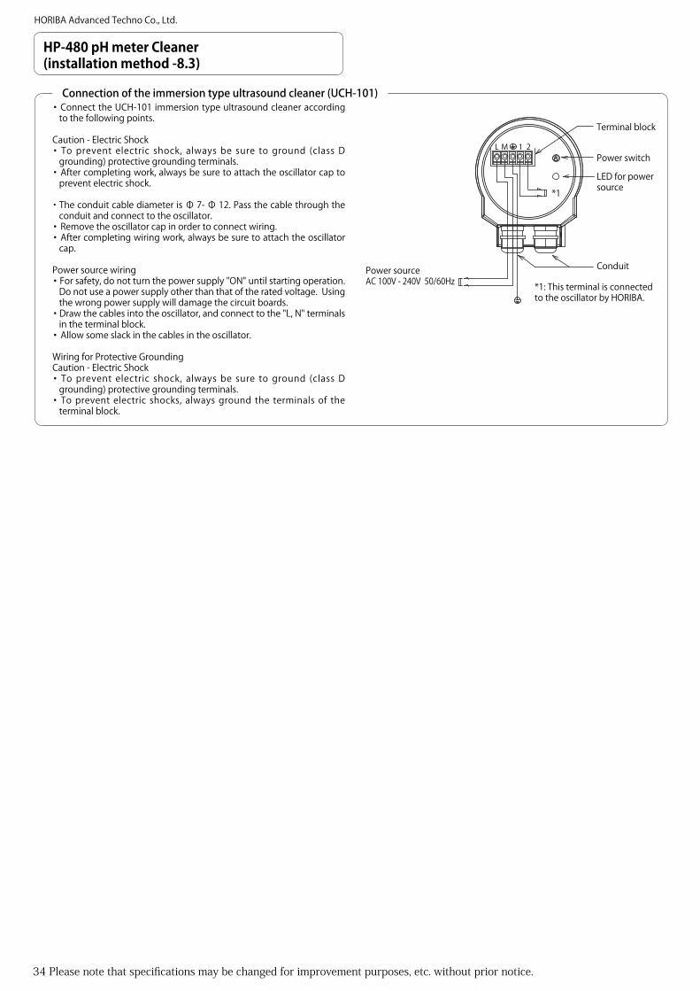
Connection of the immersion type ultrasound cleaner (UCH-101)・Connect the UCH-101 immersion type ultrasound cleaner according
to the following points.
Caution - Electric Shock・To prevent electric shock, always be sure to ground (class D
grounding) protective grounding terminals. ・After completing work, always be sure to attach the oscillator cap to
prevent electric shock.
・The conduit cable diameter is Φ 7- Φ 12. Pass the cable through the conduit and connect to the oscillator.
・Remove the oscillator cap in order to connect wiring.・After completing wiring work, always be sure to attach the oscillator
cap.
Power source wiring・For safety, do not turn the power supply "ON" until starting operation.
Do not use a power supply other than that of the rated voltage. Using the wrong power supply will damage the circuit boards.
・Draw the cables into the oscillator, and connect to the "L, N" terminals in the terminal block.
・Allow some slack in the cables in the oscillator.
Wiring for Protective GroundingCaution - Electric Shock・To prevent electric shock, always be sure to ground (class D
grounding) protective grounding terminals.・To prevent electric shocks, always ground the terminals of the
terminal block.
L M 1 2
*1
*1: This terminal is connected to the oscillator by HORIBA.
Power sourceAC 100V - 240V 50/60Hz
Terminal block
Power switch
LED for power source
Conduit

Please note that specifications may be changed for improvement purposes, etc. without prior notice. 35
HORIBA Advanced Techno Co., Ltd.
HP-480 pH meter Cleaner (installation method -9.1)
Exterior of the immersion type ultrasound cleaner (UCH-111)
Install following the conditions below to ensure the instrument is installed in stable conditions.・Install in an area where operations such as maintenance can be performed easily.・Install so that the electrode is always submerged in the measured liquid regardless of fluctuations in the level of the measured liquid.
(for immersion type ultrasound cleaner)・Avoid installing in areas with corrosive fluids or gases.・Avoid installing in areas where the surface or ambient temperature will exceed 50 , such as beside heating elements.
Installation environment
(Ø130)
55
105(115)
(168
)
1 2
4
5
Conduit
Bracket
U-Bolt5
4
3
Cover
Case2
1
NO. PARTS NAME
SUS304 M8
SUS304
NOTES
AC4C
AC4C
O.DØ7 to Ø12Cable
Maintenance space: 650 or more
50A Pole
NO. PARTS NAME
SUS316
NOTES
SUS316
PVCBracket
Hook2
3
4
5
Conduit O.D Ø7 to Ø12Cable
SUS316Ultrasonic radiator holder
6
7
Ultrasonic radiator
SUS316Stopper9
Spacer PP
Support hook SUS3168
1
AlTerminal box
Maintenance space: 2000 or more Maintenance space: 650 or more
Immersion type holder
Measured liquid level
150 or more
(83)
2028
±10
(110)
(180)
45
(Ø40)
(Ø34)
(72)
(Ø21.7)
(120
)
40(6
)
(133
)※1
(200
0)1
2
4
5
6
9
8
3
7
Exterior of the ultrasound oscillator (US-2)

36 Please note that specifications may be changed for improvement purposes, etc. without prior notice.
HORIBA Advanced Techno Co., Ltd.
HP-480 pH meter Cleaner (installation method -9.2)
Installation and removal of the immersion type ultrasound cleaner (UCH-111)
Immersion holder
Support hook
HookStopper
・The UCH-111 immersion type ultrasound cleaner and immersion holder can be installed and removed according to the following points.
Installation1. Fit the hook and support hook attached to the immersion holder
onto the immersion holder.2. Align the hook with the immersion holder and gently lower.3. When the hook catches on the stopper, close the fixture of the
immersion holder.
Removal1. Open the fixture of the immersion holder.2. Lift the immersion holder directly upward.3. Remove the hook and support hook from the oscillator holder.
Installation of the immersion type ultrasound cleaner (UCH-111)
Maintenance space: More than the holder length
Ultrasound oscillator: US-2
Pole stand: PS-50
Mounting bracket: MH-65
Immersion holder:CH-101 Series Measured
liquid level
More than 150mm
Ultrasound cleaner: UCH-111
Maintenance spaceMore than 650mm
・Install the UCH-111 immersion type ultrasound cleaner according to the following points.
・Install in an area where operations such as maintenance can be performed easily.
・Install so that the electrode is always submerged in the measured liquid regardless of fluctuations in the level of the measured liquid.
・Avoid installing in areas with corrosive fluids or gases.・Avoid installing in areas where the surface or ambient temperature will
exceed 50 , such as beside heating elements.

Please note that specifications may be changed for improvement purposes, etc. without prior notice. 37
HORIBA Advanced Techno Co., Ltd.
HP-480 pH meter Cleaner (installation method -9.3)
Connection of the immersion type ultrasound cleaner (UCH-111)
・Connect the UCH-111 immersion type ultrasound cleaner and US-2 ultrasound cleaner according to the following points.
Caution - Electric Shock・To prevent electric shock, always be sure to ground (class D
grounding) protective grounding terminals.・After completing work, always be sure to attach the oscillator cap to
prevent electric shock.
・The conduit cable diameter is Φ 7- Φ 12. Pass the cable through the conduit and connect to the oscillator.
Oscillator (US-2)・Pass the cable through the conduit and connect to the oscillator.・Remove the oscillator cap when connecting wiring.・Refer to the previous section for details on wiring connection work.・After completing wiring work, always be sure to attach the oscillator cap.Power source wiring・For safety, do not turn the power supply "ON" until starting operation.・Do not use a power supply other than that of the rated voltage. Using
the wrong power supply will damage the circuit boards.・Draw the cables into the oscillator, and connect to the "L, N" terminals
in the terminal block.・Allow some slack in the cables in the oscillator.
L M 1 2
Power sourceAC 100V - 240V 50/60Hz
Dedicated cable (accessory)
Ultrasound oscillator (US-2)Terminal block
Terminal block
Conduit Conduit Conduit
Relay Terminal Box: UCH-111
E1 2
Relay Terminal Box (UCH-111)・Pass the cable through the conduit and connect to the relay box.・Remove the relay box cap when connecting wiring.・Refer to the previous section for details on wiring connection work.・After completing wiring work, always be sure to attach the relay
box cap.

38 Please note that specifications may be changed for improvement purposes, etc. without prior notice.
HORIBA Advanced Techno Co., Ltd.
480±
5
(Ø125)
(14)
(Ø12
5)
(14)
Ø85
(305
)
(Ø130)
Rc1/8
PVC
PVC
SUS304
SUS304
PP
PPO
PPO
SUS304Range:0 to 0.5MPa
AC4C
SUS304
C3604
SUS316
O.D Ø7 to Ø12cable
PVDFFor φ6/φ4 tube
KCl reservoir
Pressurizing holder
Ultrasonic oscillator
Conduit
Cleaner mounting nut
Locking plate
Holder fixing nut
Flow chamber10
9
8
7
6
5
4
3
Pressure gauge
2
1NO. PARTS NAME NOTES
Cable clamp
Holder cap
Air inlet
Holder
Handy pump joint(option)15
14
13
12
11
Tube joint(option)16
KCl pouring port
2
9
8
6
3
1
210
(4-∅19)
(∅90)
11
12
13
145
7 10
15 16
(4-∅19)
(∅90)
110
115
97(189)
IN
OUT
Maintenance space: 150 or more
Electrode cable
JIS 10K 25A FF Flange
JIS 10K 25A FF Flange
Mai
nten
ance
spac
e65
0 or
mor
eM
aint
enan
ce sp
ace
150
or m
ore
Manual pressurization specifications (Pressurizing unit: Optional)
Instrument air specifications(Tube coupling: optional)
0.2
0.15
0.1
-50
0.05
10 25 40 55 70 10085
0.35
0.25
0.3
Relationship Between Temperature and Pressure
Usage range
Measured liquid temperature ()
Mea
sure
d liq
uid pr
essu
re (M
Pa)
HP-480 pH meter Cleaner (installation method -10.1)
Exterior of the flow type ultrasound cleaner (UCF-301)
・Install in an area where operations such as maintenance can be performed easily.・Leave at least 15 cm of maintenance space above the pressurized holder. Also, allow space to enable removal of the electrode cable.・Do not install in locations where there is substantial vibration or a lot of dust.・Install so that the measured liquid does not drain out of the line leaving the electrode exposed to the air even if the flow of measured liquid stops.・Avoid installing in areas with corrosive liquids or gases.・Avoid installing in areas where the surface or ambient temperature will exceed 50 , such as beside heating elements.・If air bubbles, slurry or solid matter that may damage the electrodes are contained in the measured liquid, remove these in advance.・Do not mount the pH flow chamber on the main line. Always install a bypass line or sampling line before installation. (Otherwise maintenance
cannot be performed without stopping the main line.)
Installation environment

Please note that specifications may be changed for improvement purposes, etc. without prior notice. 39
HORIBA Advanced Techno Co., Ltd.
HP-480 pH meter Cleaner (installation method -10.2)
Flow type ultrasound cleaner (UCF-301) plumbing
Bypass line
Bypass line Bypass line
Bypass line
Main line Main line
To install the pH flow chamber, install a bypass line in the main line and mount so that the measured liquid flows in from the bottom of the pH flow chamber and out from the side.Always install valves on the inflow and outflow sides. See [Fig.1]- If the flow rate of the measured liquid is too fast, capitation, etc. may occur, or changes in the indication values may occur due to increased pressure in the electrode supply route due to the flow rate. However, if the flow rate is too low, delays occur in the indication values. In this case, adjust the flow rate in accordance with the measurement fluid.
- In cases where there is a lot of floating matter in the measured liquid, attach a strainer to the inflow side of the holder. See [Fig.2]
Bypass line
Bypass lineStrainer
Main line
Fig.1
Fig.2Pressurization Method・There are two types of pressurization.
Manual pressurization・Prepare a pressurizing unit (screw diameter: Rc1/8) and air pump.
(Available from HORIBA as an option)・Pressurize to 0.03 - 0.05 MPa above the sample pressure. However,
do not pressurize above the specifications. (See temperature and pressure relationship chart)
・Check the pressure regularly. Air pressure reduces over time.
When using instrumentation air・To pressurize using instrumentation air, install a tube coupling. See
[Fig.3]・Remove the pressurized holder for maintenance. Construct using a
flexible pipe.・Install a regulator (with filter) near the pressurized holder, and
connect between the regulator and UCF-301 pressurized holder with a tube ( Φ 4 ×Φ 6). See [Fig.4]
・Pressurize to 0.03 - 0.05 MPa above the sample pressure. However, do not pressurize above the specifications. (See temperature and pressure relationship chart)
- Caution -・The Rc1/8 screw of the pressurized opening is made of a resin base,
and overtightening will damage the screw section.・The pressurized holder may be removed for maintenance work, etc.
therefore be sure to allow space around the air pipes when fixing in place.
150 or more maintenance space
Screw diameter: Rc1/8
Pressurizing unit (optional) When using an air pump
Tube coupling (optional) When using instrumentation air
Regulator (with filter)
Stop valve
Coil tube (optional) Φ4×Φ6
Fig.3
Fig.4
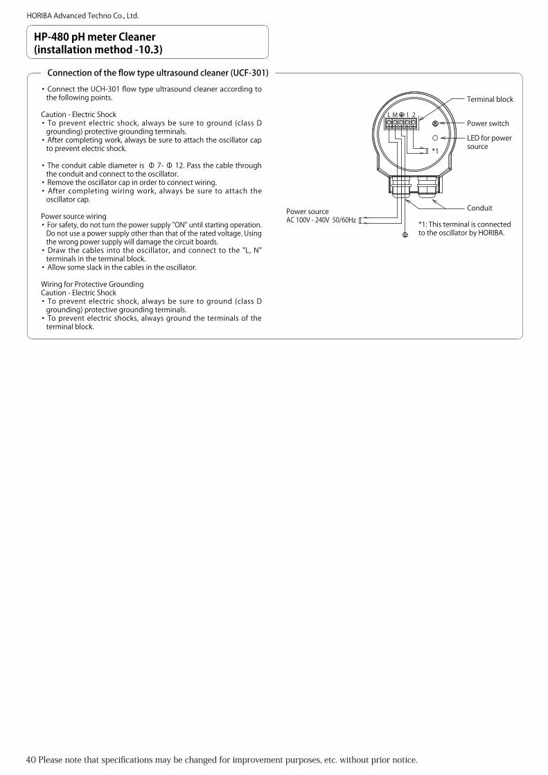
40 Please note that specifications may be changed for improvement purposes, etc. without prior notice.
HORIBA Advanced Techno Co., Ltd.
HP-480 pH meter Cleaner (installation method -10.3)
Connection of the flow type ultrasound cleaner (UCF-301)
・Connect the UCH-301 flow type ultrasound cleaner according to the following points.
Caution - Electric Shock・To prevent electric shock, always be sure to ground (class D
grounding) protective grounding terminals.・After completing work, always be sure to attach the oscillator cap
to prevent electric shock.
・The conduit cable diameter is Φ 7- Φ 12. Pass the cable through the conduit and connect to the oscillator.
・Remove the oscillator cap in order to connect wiring.・After completing wiring work, always be sure to attach the
oscillator cap.
Power source wiring・For safety, do not turn the power supply "ON" until starting operation.
Do not use a power supply other than that of the rated voltage. Using the wrong power supply will damage the circuit boards.
・Draw the cables into the oscillator, and connect to the "L, N" terminals in the terminal block.
・Allow some slack in the cables in the oscillator.
Wiring for Protective GroundingCaution - Electric Shock・To prevent electric shock, always be sure to ground (class D
grounding) protective grounding terminals.・To prevent electric shocks, always ground the terminals of the
terminal block.
L M 1 2
*1
*1: This terminal is connected to the oscillator by HORIBA.
Power sourceAC 100V - 240V 50/60Hz
Terminal block
Power switch
LED for power source
Conduit
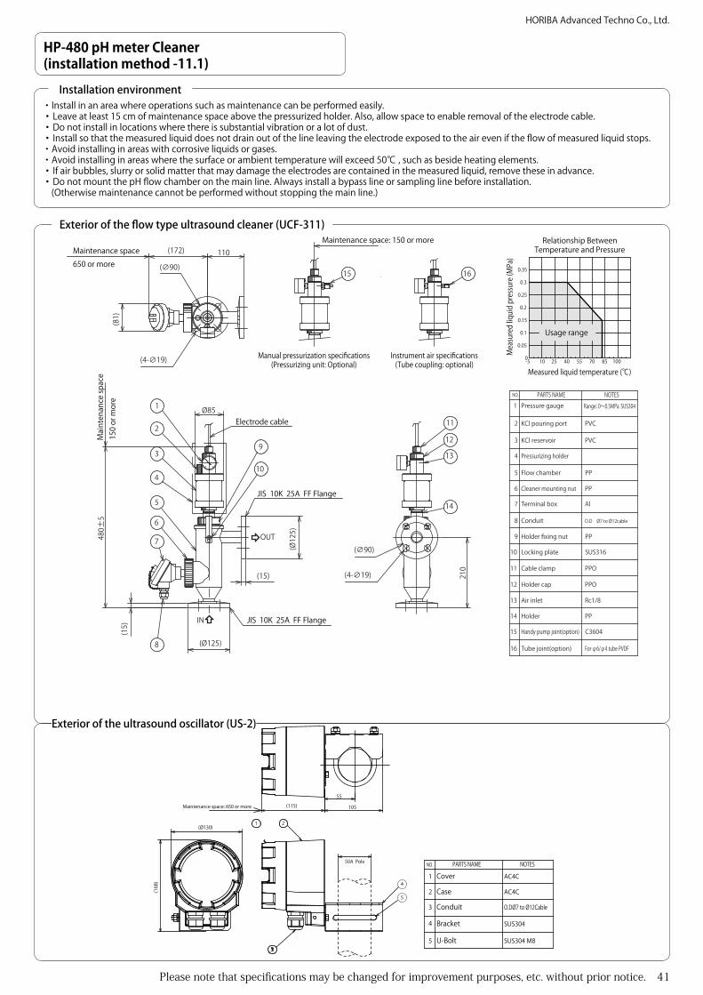
Please note that specifications may be changed for improvement purposes, etc. without prior notice. 41
HORIBA Advanced Techno Co., Ltd.
480±
5
110
(Ø125)
(15)
210
(4-∅19)
(Ø12
5)
(15)
Ø85
(4-∅19)
(∅90)
(∅90)
(172)
(81)
OUT
IN
Manual pressurization specifications (Pressurizing unit: Optional)
Instrument air specifications(Tube coupling: optional)
Maintenance space: 150 or moreMaintenance space650 or more
Mai
nten
ance
spac
e15
0 or
mor
e
Electrode cable
JIS 10K 25A FF Flange
JIS 10K 25A FF Flange
2
4
9
10
5
11
12
13
14
3
1
6
7
8
15 16
0.2
0.15
0.1
-50
0.05
10 25 40 55 70 10085
0.35
0.25
0.3
Relationship Between Temperature and Pressure
Measured liquid temperature ()
Mea
sure
d liq
uid pr
essu
re (M
Pa)
Usage range
Rc1/8
PVC
PVC
PP
PP
PPO
PPO
SUS304Range:0~0.5MPa
Al
C3604
SUS316
PVDFFor φ6/φ4 tube
KCl reservoir
Pressurizing holder
Terminal box
Holder fixing nut
Locking plate10
9
8
7
6
5
4
3
Pressure gauge
2
1NO. PARTS NAME NOTES
Cable clamp
Holder cap
Air inlet
Holder
Handy pump joint(option)15
14
13
12
11
Tube joint(option)16
PPFlow chamber
PPCleaner mounting nut
O.D Ø7 to Ø12cableConduit
KCl pouring port
HP-480 pH meter Cleaner (installation method -11.1)
Exterior of the flow type ultrasound cleaner (UCF-311)
・Install in an area where operations such as maintenance can be performed easily.・Leave at least 15 cm of maintenance space above the pressurized holder. Also, allow space to enable removal of the electrode cable.・Do not install in locations where there is substantial vibration or a lot of dust.・Install so that the measured liquid does not drain out of the line leaving the electrode exposed to the air even if the flow of measured liquid stops.・Avoid installing in areas with corrosive liquids or gases.・Avoid installing in areas where the surface or ambient temperature will exceed 50 , such as beside heating elements.・If air bubbles, slurry or solid matter that may damage the electrodes are contained in the measured liquid, remove these in advance.・Do not mount the pH flow chamber on the main line. Always install a bypass line or sampling line before installation.
(Otherwise maintenance cannot be performed without stopping the main line.)
Installation environment
(Ø130)
55
105(115)
(168
)
1 2
4
5
Conduit
Bracket
U-Bolt5
4
3
Cover
Case2
1
NO. PARTS NAME
SUS304 M8
SUS304
NOTES
AC4C
AC4C
O.DØ7 to Ø12Cable
Maintenance space: 650 or more
50A Pole
Exterior of the ultrasound oscillator (US-2)

42 Please note that specifications may be changed for improvement purposes, etc. without prior notice.
HORIBA Advanced Techno Co., Ltd.
HP-480 pH meter Cleaner (installation method -11.2)
Flow type ultrasound cleaner (UCF-311) plumbing
Bypass line
Bypass line Bypass line
Bypass line
Main line Main line
To install the pH flow chamber, install a bypass line in the main line and mount so that the measured liquid flows in from the bottom of the pH flow chamber and out from the side.Always install valves on the inflow and outflow sides. See [Fig.1]- If the flow rate of the measured liquid is too fast, capitation, etc. may occur, or changes in the indication values may occur due to increased pressure in the electrode supply route due to the flow rate. However, if the flow rate is too low, delays occur in the indication values. In this case, adjust the flow rate in accordance with the measurement fluid.
- In cases where there is a lot of floating matter in the measured liquid, attach a strainer to the inflow side of the holder. See [Fig.2]
Bypass line
Bypass line
Main line
Strainer
Fig.1
Fig.2Pressurization Method・There are two types of pressurization.
Manual pressurization・Prepare a pressurizing unit (screw diameter: Rc1/8) and air pump.
(Available from HORIBA as an option)・Pressurize to 0.03 - 0.05 MPa above the sample pressure. However,
do not pressurize above the specifications. (See temperature and pressure relationship chart)
・Check the pressure regularly. Air pressure reduces over time.
When using instrumentation air・To pressurize using instrumentation air, install a tube coupling. See
[Fig.3]・Remove the pressurized holder for maintenance. Construct using a
flexible pipe.・Install a regulator (with filter) near the pressurized holder, and
connect between the regulator and UCF-301 pressurized holder with a tube ( Φ 4 ×Φ 6). See [Fig.4]
・Pressurize to 0.03 - 0.05 MPa above the sample pressure. However, do not pressurize above the specifications. (See temperature and pressure relationship chart)
- Caution -・The Rc1/8 screw of the pressurized opening is made of a resin base,
and overtightening will damage the screw section.・The pressurized holder may be removed for maintenance work, etc.
therefore be sure to allow space around the air pipes when fixing in place.
150 or more maintenance space
Screw diameter: Rc1/8
Pressurizing unit (optional) When using an air pumpTube coupling (optional)When using instrumentation air
Regulator (with filter)
Stop valve
Coil tube (optional) Φ4×Φ6
Fig.3
Fig.4
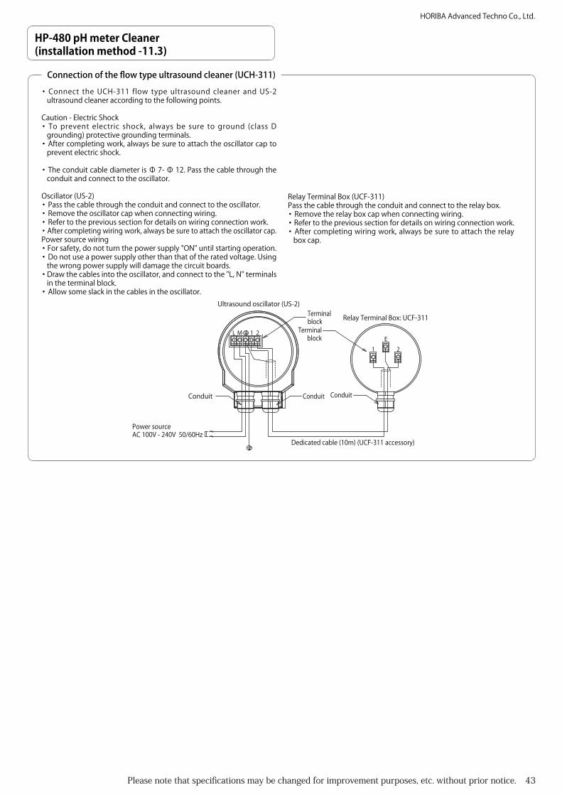
Please note that specifications may be changed for improvement purposes, etc. without prior notice. 43
HORIBA Advanced Techno Co., Ltd.
HP-480 pH meter Cleaner (installation method -11.3)
Connection of the flow type ultrasound cleaner (UCH-311)
・Connect the UCH-311 flow type ultrasound cleaner and US-2 ultrasound cleaner according to the following points.
Caution - Electric Shock・To prevent electric shock, always be sure to ground (class D
grounding) protective grounding terminals.・After completing work, always be sure to attach the oscillator cap to
prevent electric shock.
・The conduit cable diameter is Φ 7- Φ 12. Pass the cable through the conduit and connect to the oscillator.
Oscillator (US-2)・Pass the cable through the conduit and connect to the oscillator.・Remove the oscillator cap when connecting wiring.・Refer to the previous section for details on wiring connection work.・After completing wiring work, always be sure to attach the oscillator cap.Power source wiring・For safety, do not turn the power supply "ON" until starting operation.・Do not use a power supply other than that of the rated voltage. Using
the wrong power supply will damage the circuit boards.・Draw the cables into the oscillator, and connect to the "L, N" terminals
in the terminal block.・Allow some slack in the cables in the oscillator.
L M 1 2
Power sourceAC 100V - 240V 50/60Hz
Dedicated cable (10m) (UCF-311 accessory)
Ultrasound oscillator (US-2)
Relay Terminal Box: UCF-311
Conduit Conduit
Terminal block
Terminal block
Conduit
E1 2
Relay Terminal Box (UCF-311)Pass the cable through the conduit and connect to the relay box.・Remove the relay box cap when connecting wiring.・Refer to the previous section for details on wiring connection work.・After completing wiring work, always be sure to attach the relay
box cap.

44 Please note that specifications may be changed for improvement purposes, etc. without prior notice.
HORIBA Advanced Techno Co., Ltd.
(*L
2)
550+
H45
0
(230
)
1500
300
300
25 250 (25)
2525
0(2
5)
4-∅14900
(*L1
)
(Ø60.5)
(975)
∅230
Mini
mum
leve
l of m
easu
red l
iquid
: (*L3
)
Main
tena
nce s
pace
(*L4
)
H= M
ax. 1
00
(410~710) Pitch: 100
A Arrow view (Bolt fixing position)
1
2
Detector cable output
Pole stand
Maintenanceposition
Minimum level ofmeasured liquid
Detector
FloatBracket3
Holder
2
1NO. PARTS NAME NOTES
PVC
ABS,PVCSUS304
2.0m 2360 2020±50 1050-H 27002.5m 2860 2520±50 1550-H 32003.0m 3360 3020±50 2050-H 3700Units are mm. L3 length is approximate.L4 needs to be longer than the specified length.
A balancer is used in a 3m nominal length holder (FH-101-P-3.0-PH).(See the FH-101-S series exterior figure)Holder nominal length L1 L2 L3 L4
HP-480 pH meter floating type holder(Installation method - 12.1)
Exterior of the vertical floating type holder (FH-101-P series)
・Install in an area where operations such as maintenance can be performed easily.・Install so that the electrode is always submerged in the measured liquid regardless of fluctuations in the level of the measured liquid.・Avoid installing in areas with corrosive fluids or gases.・Avoid installing in areas where the surface or ambient temperature will exceed 50 , such as beside heating elements.Assembly・Details are written in the instruction manual.Mounting・ Install a movable section for the sensor cable between the holder and converter in preparation for fluctuations in the level of measured liquid
and maintenance work. ・When a balancer is installed, adjust the length of the wire so that the balancer is as the top position when the level of liquid is at the lowest.
Installation environment

Please note that specifications may be changed for improvement purposes, etc. without prior notice. 45
HORIBA Advanced Techno Co., Ltd.
(*L2
)
550+
H45
0
(320
)
1500
300
300
25 250 (25)
2525
0(2
5)
4-∅14900
(*L1
)
∅230
(Ø60.5)
(975)
Maintenanceposition
Fluctu
ation
wid
th (*
L4)
Fluctu
ation
wid
th (*
L4)
Mini
mum
leve
l of m
easu
red l
iquid
(*L3
)
H= M
ax. 1
00
Main
tena
nce s
pace
(*L5
)
(410~710) Pitch: 100
FloatBracketBalance weight5
43
HolderWire2
1NO. PARTS NAME NOTES
SUS304SUS304ABS,PVCSUS304SUS304
Detector cable output
Minimum level ofmeasured liquid
Detector
Pole stand
A Arrow view (Bolt fixing position)
2.0m 2445 2020±50 1050-H 700-H 25002.5m 2945 2520±50 1550-H 645-H 30003.0m 3445 3020±50 2050-H 590-H 3500Units are mm. L3 length is approximate.L5 needs to be longer than the specified length.
Holder nominal length L1 L2 L3 L4 L5
HP-480 pH meter floating type holder(Installation method - 12.2)
Exterior of vertical floating type holder (FH-101-S series)

46 Please note that specifications may be changed for improvement purposes, etc. without prior notice.
HORIBA Advanced Techno Co., Ltd.
Clamp
Bracket
U-Bolt5
4
3
Holder
2
1
NO. PARTS NAME NOTES
SUS304
SUS304
SUS304
SUS304
Float ABS,PVC
25A(OD 34) M8
Handrail, etc. (External diameter 34)
Fixe
d po
sitio
n
Operating range
Measured liquid level
Detector
Detector cable output
H
L
270
44
(930
)
100
400 0~11500~10505000~9506000~8507000~750800
500600700800600700800
200
300W(Working distance)HL
G:800
0~7500~8500~9500~1050
0~7500~8500~950
G:800
∅230
呼び長3.0m(3450±50)
30°
30°
30°
30°
45°
(R2450)
45°
20°
115°
(690)
Floa
t fol
low
-up
rang
e W
4-∅10 pore
2
1
HP-480 pH meter floating type holder(Installation method - 13.1)
Exterior of the inclined floating type holder (FH-201-S)
・Install in an area where operations such as maintenance can be performed easily.・Install so that the electrode is always submerged in the measured liquid regardless of fluctuations in the level of the measured liquid.・Avoid installing in areas with corrosive fluids or gases.・Avoid installing in areas where the surface or ambient temperature will exceed 50 , such as beside heating elements.Assembly・Details are written in the instruction manual.Mounting・ Install a movable section for the sensor cable between the holder and converter in preparation for fluctuations in the level of measured liquid
and maintenance work.・ Consider the weight of the instrument and flow speed of measured liquid for the attachment location (using the customer handrail, etc.) and
ensure there is sufficient strength to support the instrument.・ G:800 (holder installation dimensions) are the standard dimensions and can be changed to suit the installation environment. However, note that
in that case the float follow-up range changes. (Contact HORIBA for details.)
Installation environment
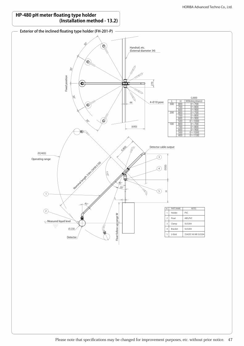
Please note that specifications may be changed for improvement purposes, etc. without prior notice. 47
HORIBA Advanced Techno Co., Ltd.
Clamp
Bracket
U-Bolt5
4
3
Holder
2
1
NO. PARTS NAME NOTES
PVC
SUS304
SUS304
SUS304
Float ABS,PVC
25A(OD 34) M8
100
400 0~11000~10005000~9006000~8007000~700800
500600700800600700800
200
300W(Working distance)HL
G:800
0~7000~8000~900
0~1000
0~7000~8000~900
Handrail, etc. (External diameter 34)
Fixe
d po
sitio
n
Operating range
Measured liquid level
Detector
Detector cable outputG:800
H
L
270
44
(930
)
45°
∅230
(R2400)
30°
30°
30°
30°
(690)
45°20°
115°
4-∅10 pore
Nominal length 3.0m (3
430±50)
Floa
t fol
low
-up
rang
e W
2
1
3
4
5
HP-480 pH meter floating type holder(Installation method - 13.2)
Exterior of the inclined floating type holder (FH-201-P)