Embed Size (px)
Citation preview
PANDUAN PROGRAM KOMPUTER UNTUK MENGHITUNG PERMEABILITAS DAN PERMITIVITAS
1. TEORI DASAR
A. Sample Preparation and Transmission Line Method
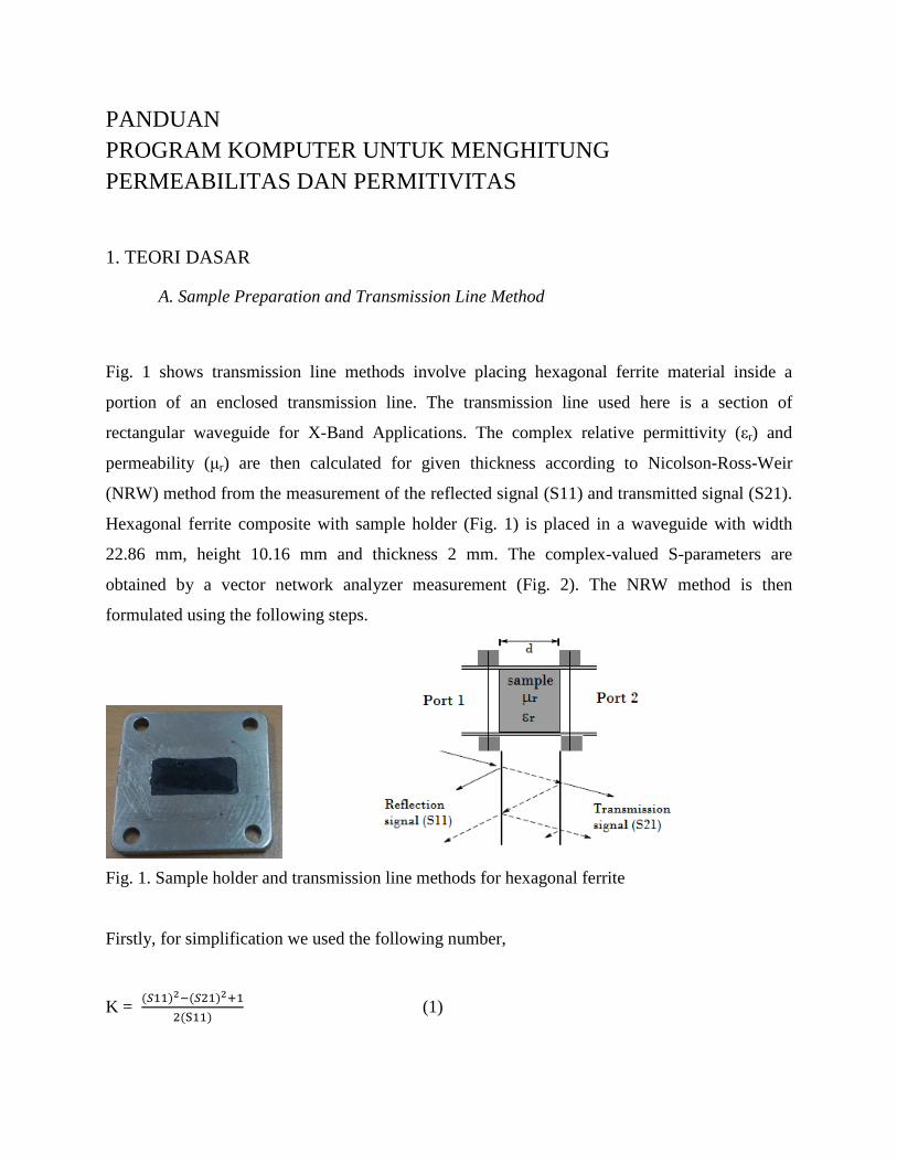
Fig. 1 shows transmission line methods involve placing hexagonal ferrite material inside a
portion of an enclosed transmission line. The transmission line used here is a section of
rectangular waveguide for X-Band Applications. The complex relative permittivity (εr) and
permeability (µr) are then calculated for given thickness according to Nicolson-Ross-Weir
(NRW) method from the measurement of the reflected signal (S11) and transmitted signal (S21).
Hexagonal ferrite composite with sample holder (Fig. 1) is placed in a waveguide with width
22.86 mm, height 10.16 mm and thickness 2 mm. The complex-valued S-parameters are
obtained by a vector network analyzer measurement (Fig. 2). The NRW method is then
formulated using the following steps.
Fig. 1. Sample holder and transmission line methods for hexagonal ferrite
Firstly, for simplification we used the following number,
K = (���)��(���)���
�(��) (1)
Then, the reflection coefficient ( Γ) is then given by
Γ = K ±√K� − 1 , |Γ|≤ 1, (2)
and the transmission coefficient (T) is given by equation
T = (��)�(��)���(�����)à (3)
Finally the complex relative permeability and permittivity of hexagonal ferrite can be formulated
by
µ = �� Γ
Λ(�� Γ)� �λ��� �
� (4)
ε = λ��� � �
λ�� − � ���� �� ��
����� (5)
where λo and λc are the free space and the cutoff wavelength and with
�Λ
� = �− � ���� �� ��
����� (6)
By equating the equation (4) and (5), The relative complex permeability can be determined and
hence thecomplex relative permittivity value.
The magnetic and electricloss tangent of a materialis defined as
tan δm = �!!�! (7)
and
tan δe = ε!!ε! , (8)
the greater the loss tangent of the material, the greater the attenuation as the wave travelsthrough
the material.
B. S-Parameter Measurement
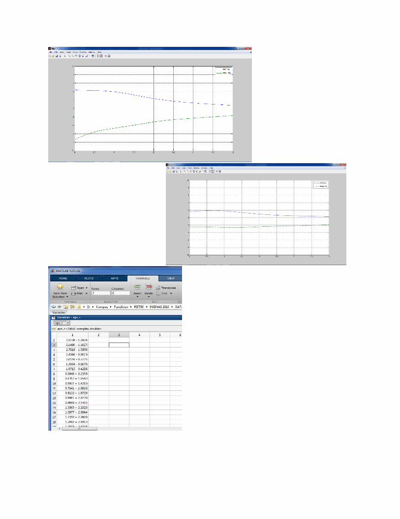
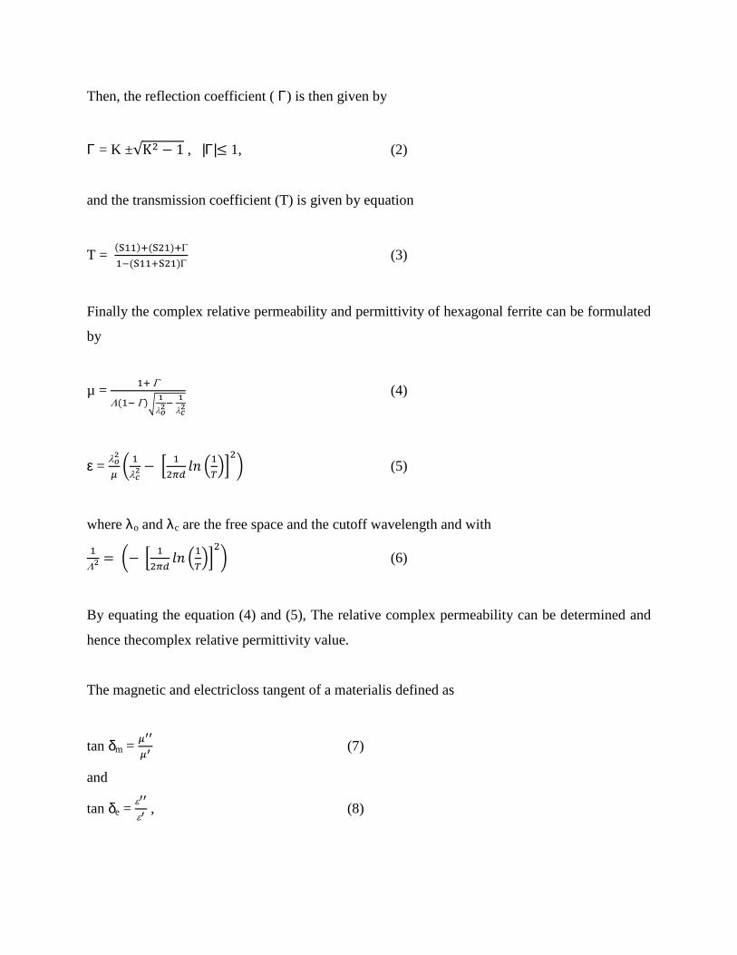
Fig. 2 shows the measurement results of s paramaters at frequencies ranging from 7 to 14 GHz.
S11 is intensities level as a function of frequency. The results confirm that in the range 7 to 14
GHz, barium hexaferrite absorb the wave which have various reflection intensity. Its suggested
from the reflection factor (S11) which has value between -10 dB to -15 dB. Further results show
there is no transmission detected in the range of frequencies 7 up to 14 GHz. It can be
understood from the transmission intensity which has value ranging from -20 to -25 GHz.
C. Magnetic and Dielectric Properties
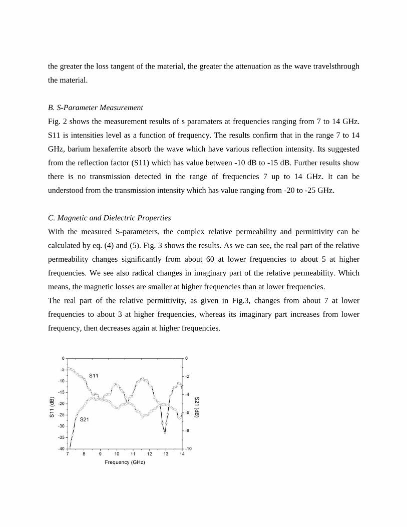
With the measured S-parameters, the complex relative permeability and permittivity can be
calculated by eq. (4) and (5). Fig. 3 shows the results. As we can see, the real part of the relative
permeability changes significantly from about 60 at lower frequencies to about 5 at higher
frequencies. We see also radical changes in imaginary part of the relative permeability. Which
means, the magnetic losses are smaller at higher frequencies than at lower frequencies.
The real part of the relative permittivity, as given in Fig.3, changes from about 7 at lower
frequencies to about 3 at higher frequencies, whereas its imaginary part increases from lower
frequency, then decreases again at higher frequencies.
Fig. 2. Results of measurement of the S-parameter of hexagonal ferrite
Fig. 3. Complex relative permeability and permittivity of hexagonal ferrite
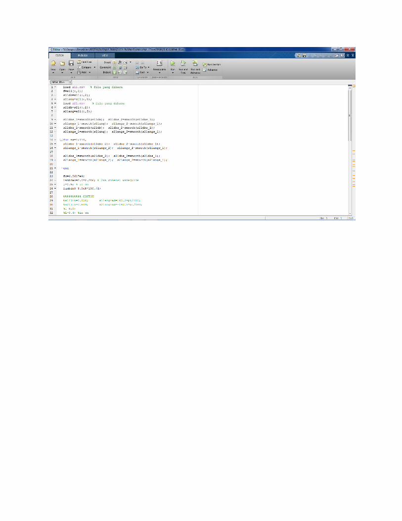
MENGHITUNG PERMEABILITAS DAN PERMITIVITAS DENGAN MAT LAB.