Embed Size (px)
Citation preview
907
Related Information
Selection Guide
Wafer Detection
Liquid Leak Detection
Liquid Level Detection
Water Detection
Color Mark Detection
Hot Melt Glue Detection
Ultrasonic
Small / Slim Object Detection
Obstacle Detection
Other Products
SQ4EX-F70/ EX-F60
FIBERSENSORS
LASERSENSORS
PHOTOELECTRICSENSORS
MICROPHOTOELECTRIC
SENSORS
AREASENSORS
LIGHT CURTAINS /SAFETY
COMPONENTSPRESSURE /
FLOWSENSORS
INDUCTIVEPROXIMITY
SENSORS
PARTICULARUSE SENSORS
SENSOROPTIONS
SIMPLEWIRE-SAVING
UNITS
WIRE-SAVING SYSTEMS
MEASUREMENTSENSORS
STATIC ELECTRICITYPREVENTION
DEVICES
LASERMARKERS
PLC
HUMAN MACHINE INTERFACES
ENERGY CONSUMPTION VISUALIZATION COMPONENTS
FA COMPONENTS
MACHINE VISION SYSTEMS
UV CURING SYSTEMS
LiquidSensor body
Leakage panLeakage pan
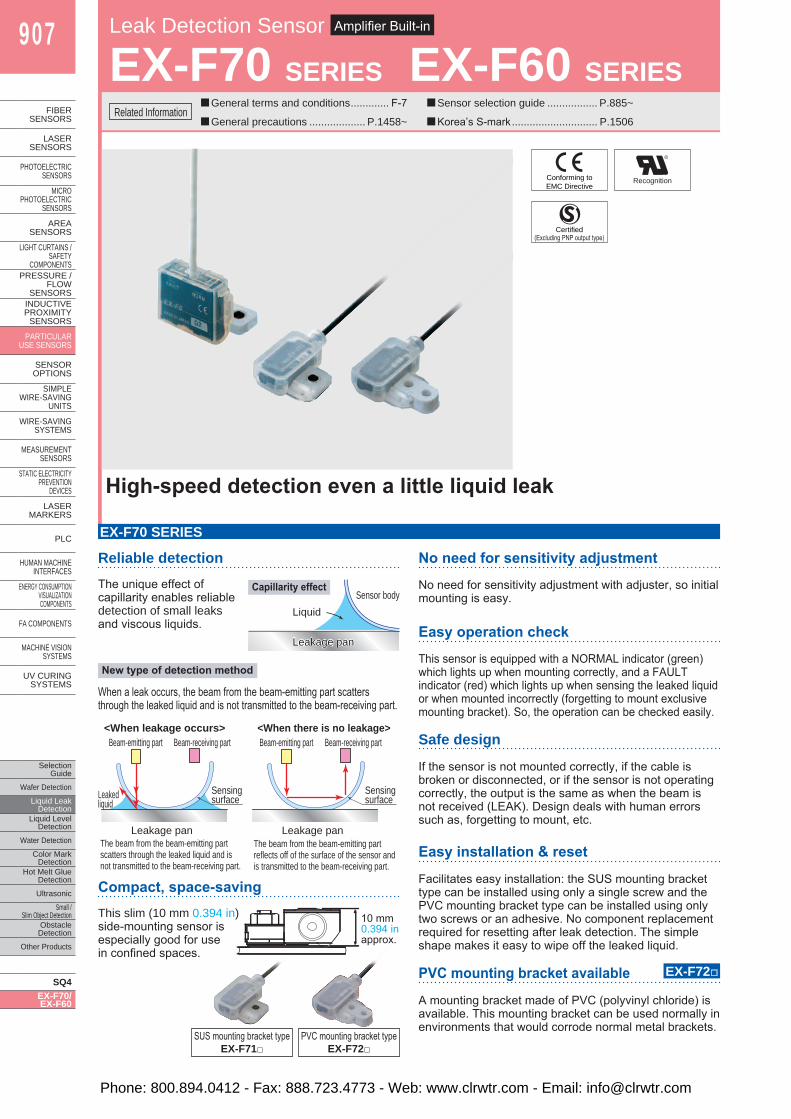
Leak Detection Sensor Amplifier Built-in
EX-F70 SERIES EX-F60 SERIES ■General terms and conditions ............. F-7
■General precautions ................... P.1458~
High-speed detection even a little liquid leak
Reliable detectionThe unique effect of capillarity enables reliable detection of small leaks and viscous liquids.
EX-F70 SERIES
No need for sensitivity adjustment
No need for sensitivity adjustment with adjuster, so initial mounting is easy.
Easy operation check
Safe design
If the sensor is not mounted correctly, if the cable is broken or disconnected, or if the sensor is not operating correctly, the output is the same as when the beam is not received (LEAK). Design deals with human errors such as, forgetting to mount, etc.
This sensor is equipped with a NORMAL indicator (green) which lights up when mounting correctly, and a FAULT indicator (red) which lights up when sensing the leaked liquid or when mounted incorrectly (forgetting to mount exclusive mounting bracket). So, the operation can be checked easily.
PVC mounting bracket available
A mounting bracket made of PVC (polyvinyl chloride) is available. This mounting bracket can be used normally in environments that would corrode normal metal brackets.
Easy installation & reset
Facilitates easy installation: the SUS mounting bracket type can be installed using only a single screw and the PVC mounting bracket type can be installed using only two screws or an adhesive. No component replacement required for resetting after leak detection. The simple shape makes it easy to wipe off the leaked liquid.
Capillarity effect
New type of detection method
When a leak occurs, the beam from the beam-emitting part scatters through the leaked liquid and is not transmitted to the beam-receiving part.
<When leakage occurs> <When there is no leakage>Beam-emitting part Beam-receiving part
Leakage pan
Leakedliquid
Sensingsurface
Beam-emitting part Beam-receiving part
Leakage pan
Sensingsurface
The beam from the beam-emitting partscatters through the leaked liquid and isnot transmitted to the beam-receiving part.
The beam from the beam-emitting partreflects off of the surface of the sensor andis transmitted to the beam-receiving part.
Compact, space-savingThis slim (10 mm 0.394 in) side-mounting sensor is especially good for use in confined spaces.
SUS mounting bracket type EX-F71□
PVC mounting bracket type EX-F72□
10 mm 0.394 in approx.
EX-F72□
Conforming toEMC Directive
Recognition
■Sensor selection guide ................. P.885~
■Korea’s S-mark ............................. P.1506
Certified(Excluding PNP output type)
Phone: 800.894.0412 - Fax: 888.723.4773 - Web: www.clrwtr.com - Email: [email protected]

Leak Detection Sensor EX-F70 SERIES EX-F60 SERIES 908
Selection GuideWafer DetectionLiquid Leak DetectionLiquid Level DetectionWater DetectionColor Mark DetectionHot Melt Glue Detection
Ultrasonic
Small / Slim Object DetectionObstacle DetectionOther Products
SQ4EX-F70/EX-F60
FIBERSENSORS
LASERSENSORS
PHOTO-ELECTRICSENSORSMICROPHOTO-ELECTRICSENSORS
AREASENSORS
LIGHTCURTAINS /SAFETYCOMPONENTSPRESSURE / FLOWSENSORS
INDUCTIVEPROXIMITYSENSORS
PARTICULARUSE SENSORS
SENSOROPTIONS
SIMPLEWIRE-SAVINGUNITS
WIRE-SAVING SYSTEMS
MEASURE-MENTSENSORSSTATIC ELECTRICITYPREVENTIONDEVICES
LASERMARKERS
PLC
HUMAN MACHINE INTERFACESENERGY CONSUMPTION VISUALIZATION COMPONENTS
FA COMPONENTS
MACHINE VISION SYSTEMS
UV CURING SYSTEMS
ORDER GUIDE
Type Appearance Sensing object Cable length Model No. Output
Gen
eral
pur
pose
SUS mounting bracket type
Water, FluorinertTM
(Note 1, 2) 2 m 6.562 ft
EX-F71 NPN open-collector transistor
EX-F71-PN PNP open-collector transistor
PVC mounting bracket type
EX-F72 NPN open-collector transistor
EX-F72-PN PNP open-collector transistor
Che
mic
al-r
esis
tant PFA mounting
bracket type Agent, such as Sulfuric acid, Hydrochloric acid, Phosphoric acid or Ammonia etc.(Note 1, 3, 4)
3 m 9.843 ft
EX-F61 NPN open-collector transistor
EX-F61-PN PNP open-collector transistor
PVC mounting bracket type
EX-F62 NPN open-collector transistor
EX-F62-PN PNP open-collector transistor
Notes: 1) Highly viscous liquid may not be detected stably.2) FluorinertTM is the world wide trademark of 3M.3) The agents mentioned above are examples.
For details, please contact our office.4) PVC mounting brackets may not be suitable for use depending on the
concentration of the detection target. For details, please contact our office.
Leak detection sensors
5 m 16.404 ft cable length type (standard: 2 m 6.562 ft or 3 m 9.843 ft) is also available.When ordering this type, suffix “-C5” to the model No. (e.g.) 5 m 16.404 ft cable length type of EX-F71-PN is “EX-F71-PN-C5”.
Simple wire-saving unit for leak detection sensor
Appearance Model No. Output
EX-FC1 Relay contact 1 a5 m 16.404 ft cable length type
PFA enclosure gives excellent chemical resistanceThe sensor enclosure and the cable sheath are made from PFA which is highly resistant to chemicals. Accurate sensing is achieved even if there are leaks of chemicals such as sulfuric acid, hydrochloric acid or ammonia.
EX-F60 SERIES
Compact, space-savingEven with its built-in amplifier, the size is compact at W26 × H19 × D9 mm W1.024 × H0.748 × D0.354 in, so that it can be used even in narrow spaces.
Wire-saving unit made especially for connecting leak detection sensors!
EX-FC1
Easy installation & resetThe simplified shape makes it easy to clean up after liquid leaks, simply by wiping off the liquid, and no parts need to be replaced.
Space savings are significant, as the ultra-thin & compact EX-FC1 has main unit body dimensions of only W20 × H80 × D52 mm W0.787 × H3.150 × D2.047 in.
Slim & compact
PFA coating
PFA case
26 mm 1.024 in 26 mm 1.024 in
19 mm 0.748 in19 mm 0.748 in9 mm
0.354 in 9 mm
0.354 in
Connects easily with one-touch connectorConnections are made by simply inserting the leak detection sensor cable leads into the snap male connector SL-CP1, then push until the connector snap-locks! This saves the time and the trouble of stripping the insulation from each lead before attaching to terminals.
Saves wiring! Now connects up to 8 leak detection sensorsEX-FC1 is a simple wire-saving unit for exclusive use with EX-F71/F72, EX-F61/F62 leak detection sensors.(It can be used with general sensors as well.)EX-FC1 integrates the outputs from up to 8 leak detection sensors into a single OR output, so significant wiring and space savings are achieved.* Even with only one leak detection sensor connected, an
OFF signal is output if the sensor detects liquid leakage,or if the unit has been installed incorrectly.
Phone: 800.894.0412 - Fax: 888.723.4773 - Web: www.clrwtr.com - Email: [email protected]
909 Leak Detection Sensor EX-F70 SERIES EX-F60 SERIES
Selection GuideWafer
DetectionLiquid Leak
DetectionLiquid Level
DetectionWater
DetectionColor Mark
DetectionHot Melt Glue
Detection
Ultrasonic
Small / Slim Object Detection
Obstacle Detection
Other Products
SQ4EX-F70/EX-F60
FIBERSENSORS
LASERSENSORS
PHOTO-ELECTRICSENSORS
MICROPHOTO-
ELECTRICSENSORS
AREASENSORS
LIGHTCURTAINS /
SAFETYCOMPONENTS
PRESSURE / FLOW
SENSORS
INDUCTIVEPROXIMITY
SENSORS
PARTICULARUSE
SENSORS
SENSOROPTIONS
SIMPLEWIRE-SAVING
UNITS
WIRE-SAVING SYSTEMS
MEASURE-MENT
SENSORSSTATIC
ELECTRICITYPREVENTION
DEVICES
LASERMARKERS
PLC
HUMAN MACHINE
INTERFACESENERGY
CONSUMPTION VISUALIZATION COMPONENTS
FA COMPONENTS
MACHINE VISION
SYSTEMS
UV CURING
SYSTEMS
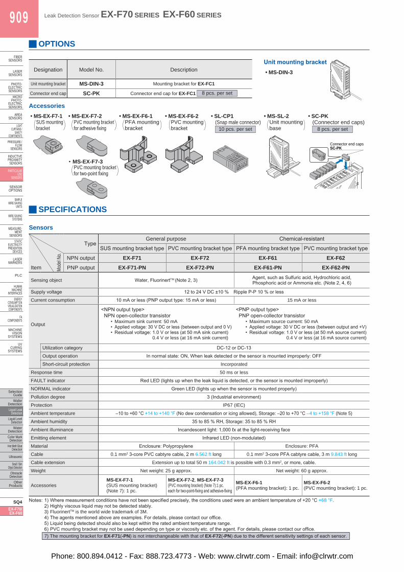
OPTIONS
Designation Model No. Description
Unit mounting bracket MS-DIN-3 Mounting bracket for EX-FC1
Connector end cap SC-PK Connector end cap for EX-FC1 8 pcs. per set
Unit mounting bracket• MS-DIN-3
• MS-SL-2
Accessories• MS-EX-F7-1 • MS-EX-F7-2 • MS-EX-F6-1 • MS-EX-F6-2 • SL-CP1
(Snap male connector)10 pcs. per set
• SC-PK(Connector end caps)
8 pcs. per set
• MS-EX-F7-31
23
4
Connector end capsSC-PK
SPECIFICATIONS
Sensors
TypeGeneral purpose Chemical-resistant
SUS mounting bracket type PVC mounting bracket type PFA mounting bracket type PVC mounting bracket type
Mode
l No. NPN output EX-F71 EX-F72 EX-F61 EX-F62
Item PNP output EX-F71-PN EX-F72-PN EX-F61-PN EX-F62-PN
Sensing object Water, FluorinertTM (Note 2, 3) Agent, such as Sulfuric acid, Hydrochloric acid,Phosphoric acid or Ammonia etc. (Note 2, 4, 6)
Supply voltage 12 to 24 V DC ±10 % Ripple P-P 10 % or less
Current consumption 10 mA or less (PNP output type: 15 mA or less) 15 mA or less
Output
<NPN output type>NPN open-collector transistor
• Maximum sink current: 50 mA• Applied voltage: 30 V DC or less (between output and 0 V)• Residual voltage: 1.0 V or less (at 50 mA sink current)
0.4 V or less (at 16 mA sink current)
<PNP output type>PNP open-collector transistor
• Maximum source current: 50 mA• Applied voltage: 30 V DC or less (between output and +V)• Residual voltage: 1.0 V or less (at 50 mA source current)
0.4 V or less (at 16 mA source current)
Utilization category DC-12 or DC-13
Output operation In normal state: ON, When leak detected or the sensor is mounted improperly: OFF
Short-circuit protection Incorporated
Response time 50 ms or less
FAULT indicator Red LED (lights up when the leak liquid is detected, or the sensor is mounted improperly)
NORMAL indicator Green LED (lights up when the sensor is mounted properly)
Pollution degree 3 (Industrial environment)
Protection IP67 (IEC)
Ambient temperature –10 to +60 °C +14 to +140 °F (No dew condensation or icing allowed), Storage: –20 to +70 °C – 4 to +158 °F (Note 5)
Ambient humidity 35 to 85 % RH, Storage: 35 to 85 % RH
Ambient illuminance Incandescent light: 1,000 ℓx at the light-receiving face
Emitting element Infrared LED (non-modulated)
Material Enclosure: Polypropylene Enclosure: PFA
Cable 0.1 mm2 3-core PVC cabtyre cable, 2 m 6.562 ft long 0.1 mm2 3-core PFA cabtyre cable, 3 m 9.843 ft long
Cable extension Extension up to total 50 m 164.042 ft is possible with 0.3 mm2, or more, cable.
Weight Net weight: 25 g approx. Net weight: 60 g approx.
AccessoriesMS-EX-F7-1(SUS mounting bracket)(Note 7): 1 pc.
MS-EX-F7-2, MS-EX-F7-3(PVC mounting bracket) (Note 7):1 pc. each for two-point-fixing and adhesive-fixing
MS-EX-F6-1(PFA mounting bracket): 1 pc.
MS-EX-F6-2(PVC mounting bracket): 1 pc.
Notes: 1) Where measurement conditions have not been specified precisely, the conditions used were an ambient temperature of +20 °C +68 °F.2) Highly viscous liquid may not be detected stably.3) FluorinertTM is the world wide trademark of 3M.4) The agents mentioned above are examples. For details, please contact our office.5) Liquid being detected should also be kept within the rated ambient temperature range.6) PVC mounting bracket may not be used depending on type or viscosity etc. of the agent. For details, please contact our office.7) The mounting bracket for EX-F71(-PN) is not interchangeable with that of EX-F72(-PN) due to the different sensitivity settings of each sensor.
SUS mounting bracket
PVC mounting bracket for adhesive fixing
PFA mounting bracket
PVC mounting bracket
Unit mounting base
PVC mounting bracketfor two-point fixing
Phone: 800.894.0412 - Fax: 888.723.4773 - Web: www.clrwtr.com - Email: [email protected]
Leak Detection Sensor EX-F70 SERIES EX-F60 SERIES 910
Selection GuideWafer DetectionLiquid Leak DetectionLiquid Level DetectionWater DetectionColor Mark DetectionHot Melt Glue Detection
Ultrasonic
Small / Slim Object DetectionObstacle DetectionOther Products
SQ4EX-F70/EX-F60
FIBERSENSORS
LASERSENSORS
PHOTO-ELECTRICSENSORSMICROPHOTO-ELECTRICSENSORS
AREASENSORS
LIGHTCURTAINS /SAFETYCOMPONENTSPRESSURE / FLOWSENSORS
INDUCTIVEPROXIMITYSENSORS
PARTICULARUSE SENSORS
SENSOROPTIONS
SIMPLEWIRE-SAVINGUNITS
WIRE-SAVING SYSTEMS
MEASURE-MENTSENSORSSTATIC ELECTRICITYPREVENTIONDEVICES
LASERMARKERS
PLC
HUMAN MACHINE INTERFACESENERGY CONSUMPTION VISUALIZATION COMPONENTS
FA COMPONENTS
MACHINE VISION SYSTEMS
UV CURING SYSTEMS
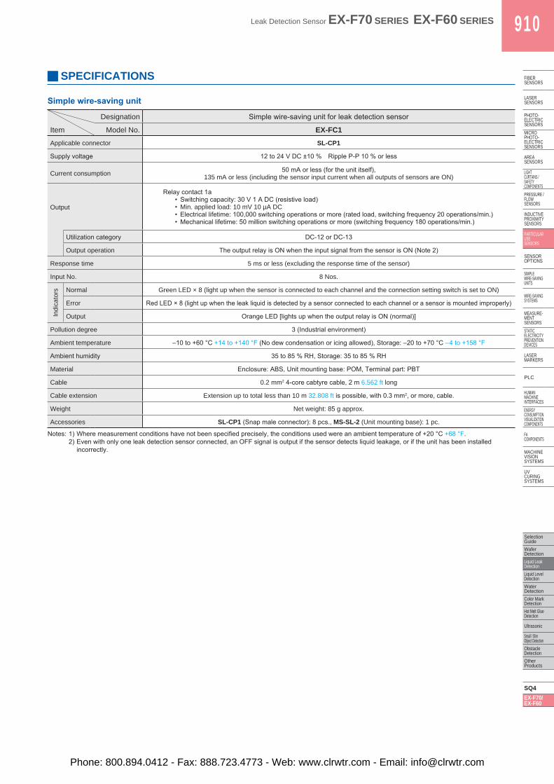
SPECIFICATIONS
Simple wire-saving unit
Designation Simple wire-saving unit for leak detection sensor
Item Model No. EX-FC1Applicable connector SL-CP1
Supply voltage 12 to 24 V DC ±10 % Ripple P-P 10 % or less
Current consumption 50 mA or less (for the unit itself),135 mA or less (including the sensor input current when all outputs of sensors are ON)
Output
Relay contact 1a• Switching capacity: 30 V 1 A DC (resistive load)• Min. applied load: 10 mV 10 µA DC• Electrical lifetime: 100,000 switching operations or more (rated load, switching frequency 20 operations/min.)• Mechanical lifetime: 50 million switching operations or more (switching frequency 180 operations/min.)
Utilization category DC-12 or DC-13
Output operation The output relay is ON when the input signal from the sensor is ON (Note 2)
Response time 5 ms or less (excluding the response time of the sensor)
Input No. 8 Nos.
Indi
cato
rs Normal Green LED × 8 (light up when the sensor is connected to each channel and the connection setting switch is set to ON)
Error Red LED × 8 (light up when the leak liquid is detected by a sensor connected to each channel or a sensor is mounted improperly)
Output Orange LED [lights up when the output relay is ON (normal)]
Pollution degree 3 (Industrial environment)
Ambient temperature –10 to +60 °C +14 to +140 °F (No dew condensation or icing allowed), Storage: –20 to +70 °C –4 to +158 °F
Ambient humidity 35 to 85 % RH, Storage: 35 to 85 % RH
Material Enclosure: ABS, Unit mounting base: POM, Terminal part: PBT
Cable 0.2 mm2 4-core cabtyre cable, 2 m 6.562 ft long
Cable extension Extension up to total less than 10 m 32.808 ft is possible, with 0.3 mm2, or more, cable.
Weight Net weight: 85 g approx.
Accessories SL-CP1 (Snap male connector): 8 pcs., MS-SL-2 (Unit mounting base): 1 pc.
Notes: 1) Where measurement conditions have not been specified precisely, the conditions used were an ambient temperature of +20 °C +68 °F.2) Even with only one leak detection sensor connected, an OFF signal is output if the sensor detects liquid leakage, or if the unit has been installed
incorrectly.
Phone: 800.894.0412 - Fax: 888.723.4773 - Web: www.clrwtr.com - Email: [email protected]
911 Leak Detection Sensor EX-F70 SERIES EX-F60 SERIES
Selection GuideWafer
DetectionLiquid Leak
DetectionLiquid Level
DetectionWater
DetectionColor Mark
DetectionHot Melt Glue
Detection
Ultrasonic
Small / Slim Object Detection
Obstacle Detection
Other Products
SQ4EX-F70/EX-F60
FIBERSENSORS
LASERSENSORS
PHOTO-ELECTRICSENSORS
MICROPHOTO-
ELECTRICSENSORS
AREASENSORS
LIGHTCURTAINS /
SAFETYCOMPONENTS
PRESSURE / FLOW
SENSORS
INDUCTIVEPROXIMITY
SENSORS
PARTICULARUSE
SENSORS
SENSOROPTIONS
SIMPLEWIRE-SAVING
UNITS
WIRE-SAVING SYSTEMS
MEASURE-MENT
SENSORSSTATIC
ELECTRICITYPREVENTION
DEVICES
LASERMARKERS
PLC
HUMAN MACHINE
INTERFACESENERGY
CONSUMPTION VISUALIZATION COMPONENTS
FA COMPONENTS
MACHINE VISION
SYSTEMS
UV CURING
SYSTEMS
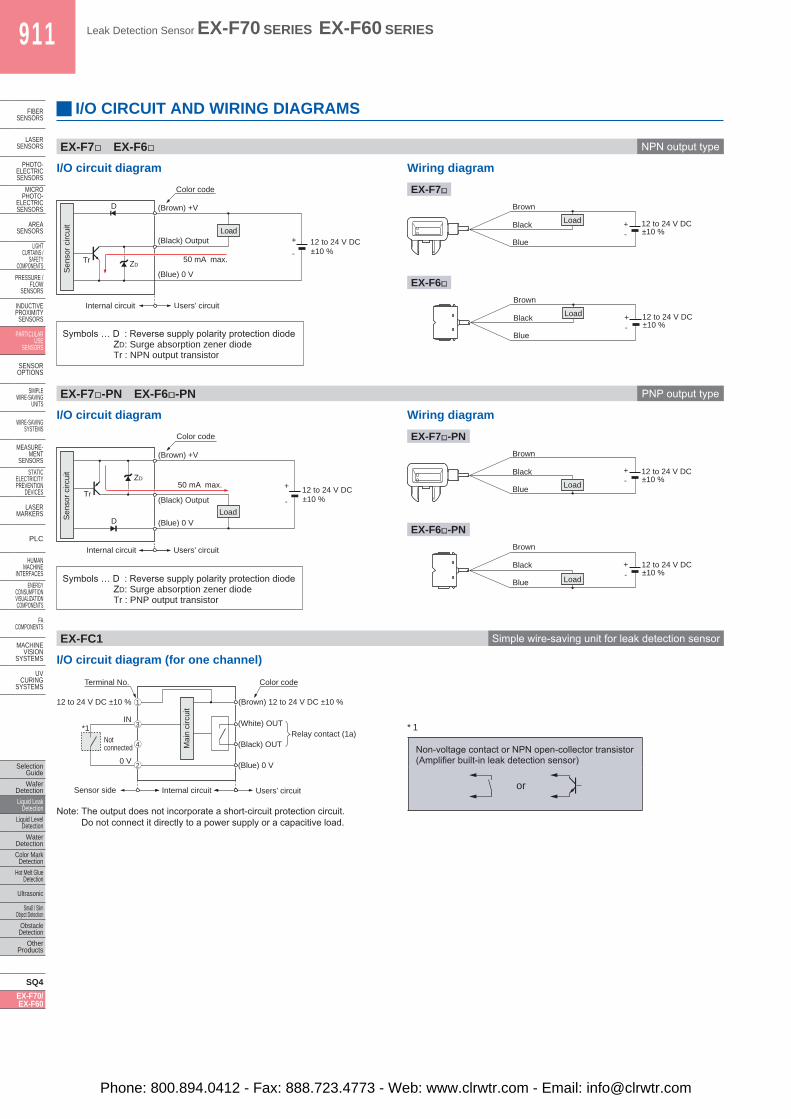
I/O CIRCUIT AND WIRING DIAGRAMS
EX-F7□ EX-F6□ NPN output type
I/O circuit diagram Wiring diagram
EX-F7□
EX-F6□
Symbols … D : Reverse supply polarity protection diodeZD: Surge absorption zener diodeTr : NPN output transistor
Users’ circuit Internal circuit
50 mA max.
(Blue) 0 V
(Brown) +V
(Black) Output
Color code
12 to 24 V DC±10 %
Tr
D
ZD
+
-
Load
Sen
sor c
ircui
t
Blue
Brown
Black 12 to 24 V DC ±10 %
Load + -
Blue
Brown
Black 12 to 24 V DC ±10 %
Load + -
EX-F7□-PN EX-F6□-PN PNP output type
I/O circuit diagram Wiring diagram
EX-F7□-PN
EX-F6□-PN
I/O circuit diagram (for one channel)
Note: The output does not incorporate a short-circuit protection circuit. Do not connect it directly to a power supply or a capacitive load.
* 1
Non-voltage contact or NPN open-collector transistor(Amplifier built-in leak detection sensor)
or
D
ZD
Tr +
-
Users’ circuit Internal circuit
(Brown) +V
(Black) Output
(Blue) 0 V
Color code
50 mA max.
Load
Sen
sor c
ircui
t
12 to 24 V DC±10 %
Blue
Brown
Black 12 to 24 V DC ±10 %
Load
+ -
Blue
Brown
Black 12 to 24 V DC ±10 %
Load
+ -
Mai
n ci
rcui
t
Internal circuit
Terminal No. Color code
(Brown) 12 to 24 V DC ±10 %12 to 24 V DC ±10 %
(White) OUT
(Black) OUT
(Blue) 0 V
Sensor side
IN
0 V
Not connected
1
3
2
4
Users’ circuit
*1 Relay contact (1a)
Symbols … D : Reverse supply polarity protection diodeZD: Surge absorption zener diodeTr : PNP output transistor
EX-FC1 Simple wire-saving unit for leak detection sensor
Phone: 800.894.0412 - Fax: 888.723.4773 - Web: www.clrwtr.com - Email: [email protected]
Leak Detection Sensor EX-F70 SERIES EX-F60 SERIES 912
Selection GuideWafer DetectionLiquid Leak DetectionLiquid Level DetectionWater DetectionColor Mark DetectionHot Melt Glue Detection
Ultrasonic
Small / Slim Object DetectionObstacle DetectionOther Products
SQ4EX-F70/EX-F60
FIBERSENSORS
LASERSENSORS
PHOTO-ELECTRICSENSORSMICROPHOTO-ELECTRICSENSORS
AREASENSORS
LIGHTCURTAINS /SAFETYCOMPONENTSPRESSURE / FLOWSENSORS
INDUCTIVEPROXIMITYSENSORS
PARTICULARUSE SENSORS
SENSOROPTIONS
SIMPLEWIRE-SAVINGUNITS
WIRE-SAVING SYSTEMS
MEASURE-MENTSENSORSSTATIC ELECTRICITYPREVENTIONDEVICES
LASERMARKERS
PLC
HUMAN MACHINE INTERFACESENERGY CONSUMPTION VISUALIZATION COMPONENTS
FA COMPONENTS
MACHINE VISION SYSTEMS
UV CURING SYSTEMS
PRECAUTIONS FOR PROPER USE
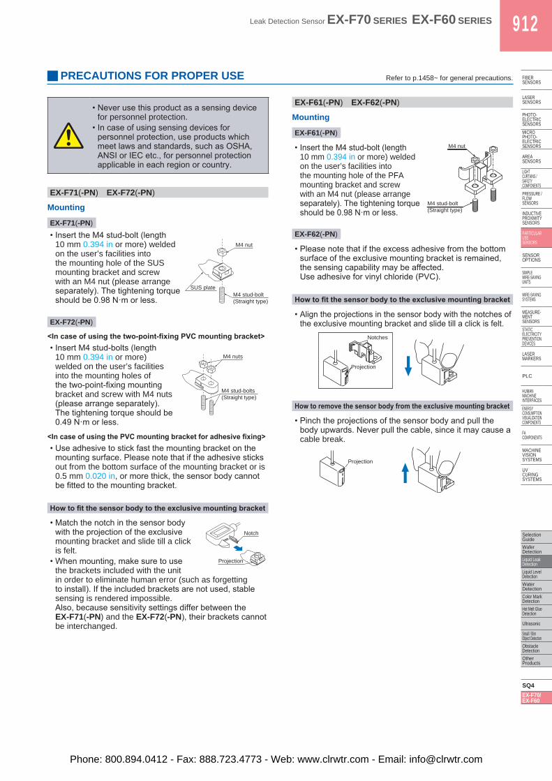
EX-F71(-PN) EX-F72(-PN)
Mounting
EX-F71(-PN)
• Insert the M4 stud-bolt (length10 mm 0.394 in or more) weldedon the user’s facilities intothe mounting hole of the SUSmounting bracket and screwwith an M4 nut (please arrangeseparately). The tightening torqueshould be 0.98 N·m or less.
EX-F72(-PN)
<In case of using the two-point-fixing PVC mounting bracket>• Insert M4 stud-bolts (length
10 mm 0.394 in or more)welded on the user’s facilitiesinto the mounting holes ofthe two-point-fixing mountingbracket and screw with M4 nuts(please arrange separately).The tightening torque should be0.49 N·m or less.
<In case of using the PVC mounting bracket for adhesive fixing>• Use adhesive to stick fast the mounting bracket on the
mounting surface. Please note that if the adhesive sticksout from the bottom surface of the mounting bracket or is0.5 mm 0.020 in, or more thick, the sensor body cannotbe fitted to the mounting bracket.
How to fit the sensor body to the exclusive mounting bracket
• Match the notch in the sensor bodywith the projection of the exclusivemounting bracket and slide till a clickis felt.
• When mounting, make sure to use the brackets included with the unitin order to eliminate human error (such as forgettingto install). If the included brackets are not used, stablesensing is rendered impossible.Also, because sensitivity settings differ between theEX-F71(-PN) and the EX-F72(-PN), their brackets cannotbe interchanged.
EX-F61(-PN) EX-F62(-PN)
Mounting
EX-F61(-PN)
• Insert the M4 stud-bolt (length10 mm 0.394 in or more) weldedon the user’s facilities intothe mounting hole of the PFAmounting bracket and screwwith an M4 nut (please arrangeseparately). The tightening torqueshould be 0.98 N·m or less.
EX-F62(-PN)
• Please note that if the excess adhesive from the bottomsurface of the exclusive mounting bracket is remained,the sensing capability may be affected.Use adhesive for vinyl chloride (PVC).
How to fit the sensor body to the exclusive mounting bracket
• Align the projections in the sensor body with the notches ofthe exclusive mounting bracket and slide till a click is felt.
How to remove the sensor body from the exclusive mounting bracket
• Pinch the projections of the sensor body and pull thebody upwards. Never pull the cable, since it may cause acable break.
M4 stud-bolt(Straight type)
M4 nut
SUS plate
M4 stud-bolts(Straight type)
M4 nuts
Notch
Projection
M4 nut
M4 stud-bolt(Straight type)
Projection
Notches
Projection
• Never use this product as a sensing devicefor personnel protection.
• In case of using sensing devices forpersonnel protection, use products whichmeet laws and standards, such as OSHA,ANSI or IEC etc., for personnel protectionapplicable in each region or country.
Refer to p.1458~ for general precautions.
Phone: 800.894.0412 - Fax: 888.723.4773 - Web: www.clrwtr.com - Email: [email protected]
913 Leak Detection Sensor EX-F70 SERIES EX-F60 SERIES
Selection GuideWafer
DetectionLiquid Leak
DetectionLiquid Level
DetectionWater
DetectionColor Mark
DetectionHot Melt Glue
Detection
Ultrasonic
Small / Slim Object Detection
Obstacle Detection
Other Products
SQ4EX-F70/EX-F60
FIBERSENSORS
LASERSENSORS
PHOTO-ELECTRICSENSORS
MICROPHOTO-
ELECTRICSENSORS
AREASENSORS
LIGHTCURTAINS /
SAFETYCOMPONENTS
PRESSURE / FLOW
SENSORS
INDUCTIVEPROXIMITY
SENSORS
PARTICULARUSE
SENSORS
SENSOROPTIONS
SIMPLEWIRE-SAVING
UNITS
WIRE-SAVING SYSTEMS
MEASURE-MENT
SENSORSSTATIC
ELECTRICITYPREVENTION
DEVICES
LASERMARKERS
PLC
HUMAN MACHINE
INTERFACESENERGY
CONSUMPTION VISUALIZATION COMPONENTS
FA COMPONENTS
MACHINE VISION
SYSTEMS
UV CURING
SYSTEMS
PRECAUTIONS FOR PROPER USE
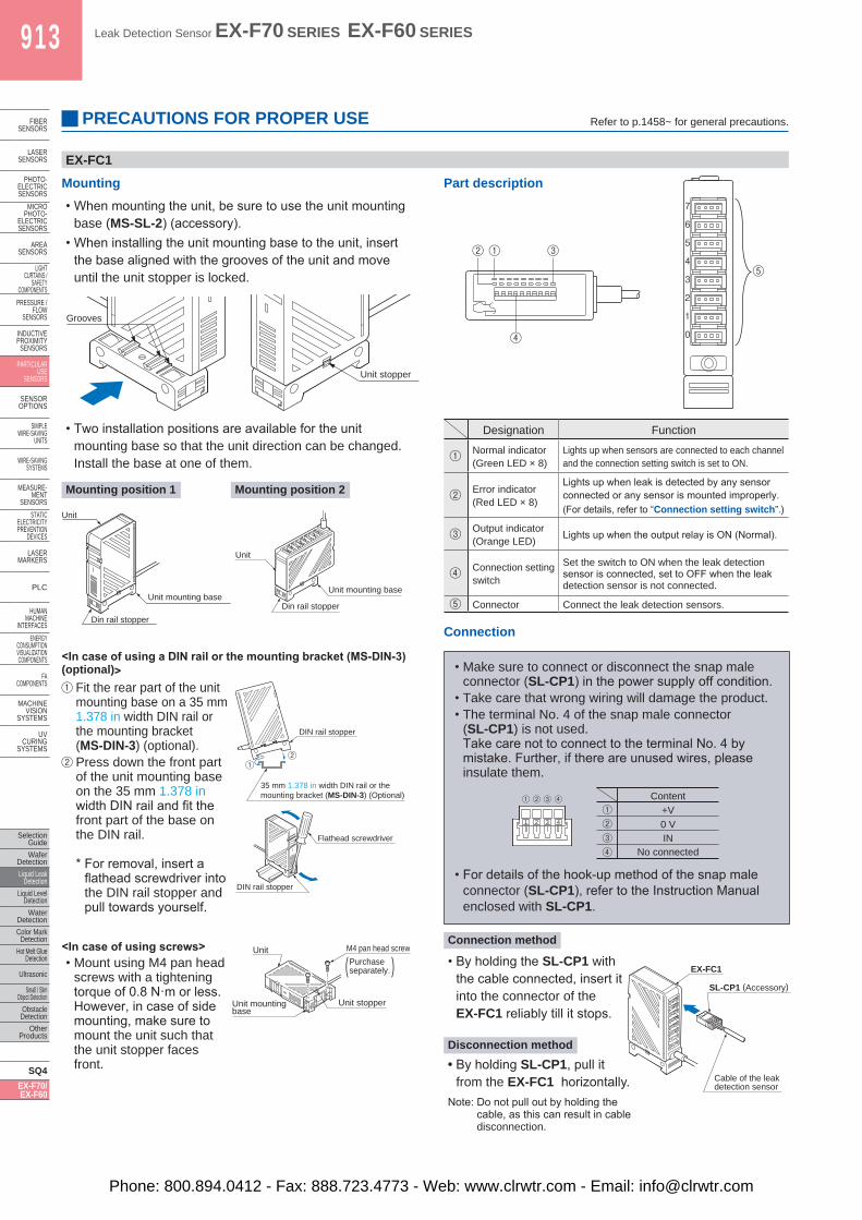
EX-FC1
Mounting• When mounting the unit, be sure to use the unit mounting
base (MS-SL-2) (accessory).• When installing the unit mounting base to the unit, insert
the base aligned with the grooves of the unit and moveuntil the unit stopper is locked.
• Two installation positions are available for the unitmounting base so that the unit direction can be changed.Install the base at one of them.
Mounting position 1 Mounting position 2
˂In case of using a DIN rail or the mounting bracket (MS-DIN-3) (optional)˃
Fit the rear part of the unit mounting base on a 35 mm 1.378 in width DIN rail or the mounting bracket (MS-DIN-3) (optional). Press down the front part of the unit mounting base on the 35 mm 1.378 in width DIN rail and fit the front part of the base on the DIN rail.
* For removal, insert aflathead screwdriver intothe DIN rail stopper andpull towards yourself.
Designation Function
Normal indicator(Green LED × 8)
Lights up when sensors are connected to each channel and the connection setting switch is set to ON.
Error indicator(Red LED × 8)
Lights up when leak is detected by any sensor connected or any sensor is mounted improperly.(For details, refer to “Connection setting switch”.)
Output indicator(Orange LED) Lights up when the output relay is ON (Normal).
Connection setting switch
Set the switch to ON when the leak detection sensor is connected, set to OFF when the leak detection sensor is not connected.
Connector Connect the leak detection sensors.
Part description
Grooves
Unit stopper
Unit
Unit mounting base
Din rail stopper
7
6
5
4
3
2
1
0
Unit
Unit mounting base
Din rail stopper
DIN rail stopper
35 mm 1.378 in width DIN rail or the mounting bracket (MS-DIN-3) (Optional)
Flathead screwdriver
DIN rail stopper
Unit stopperUnit mounting base
Unit
(Purchase separately.
M4 pan head screw
)
④
① ③ ②
⑤
7
6
5
4
3
2
1
0
Connection method
• Make sure to connect or disconnect the snap maleconnector (SL-CP1) in the power supply off condition.
• Take care that wrong wiring will damage the product.• The terminal No. 4 of the snap male connector
(SL-CP1) is not used.Take care not to connect to the terminal No. 4 bymistake. Further, if there are unused wires, pleaseinsulate them.
1 2 3 41 2 3 4
Content+V0 VIN
No connected
• For details of the hook-up method of the snap maleconnector (SL-CP1), refer to the Instruction Manualenclosed with SL-CP1.
• By holding the SL-CP1 withthe cable connected, insert itinto the connector of theEX-FC1 reliably till it stops.
Disconnection method• By holding SL-CP1, pull it
from the EX-FC1 horizontally.Note: Do not pull out by holding the
cable, as this can result in cable disconnection.
7
6
5
4
3
2
1
0
EX-FC1
SL-CP1 (Accessory)
Cable of the leak detection sensor
Connection
˂In case of using screws˃• Mount using M4 pan head
screws with a tighteningtorque of 0.8 N·m or less.However, in case of sidemounting, make sure tomount the unit such thatthe unit stopper facesfront.
Refer to p.1458~ for general precautions.
Phone: 800.894.0412 - Fax: 888.723.4773 - Web: www.clrwtr.com - Email: [email protected]
Leak Detection Sensor EX-F70 SERIES EX-F60 SERIES 914
Selection GuideWafer DetectionLiquid Leak DetectionLiquid Level DetectionWater DetectionColor Mark DetectionHot Melt Glue Detection
Ultrasonic
Small / Slim Object DetectionObstacle DetectionOther Products
SQ4EX-F70/EX-F60
FIBERSENSORS
LASERSENSORS
PHOTO-ELECTRICSENSORSMICROPHOTO-ELECTRICSENSORS
AREASENSORS
LIGHTCURTAINS /SAFETYCOMPONENTSPRESSURE / FLOWSENSORS
INDUCTIVEPROXIMITYSENSORS
PARTICULARUSE SENSORS
SENSOROPTIONS
SIMPLEWIRE-SAVINGUNITS
WIRE-SAVING SYSTEMS
MEASURE-MENTSENSORSSTATIC ELECTRICITYPREVENTIONDEVICES
LASERMARKERS
PLC
HUMAN MACHINE INTERFACESENERGY CONSUMPTION VISUALIZATION COMPONENTS
FA COMPONENTS
MACHINE VISION SYSTEMS
UV CURING SYSTEMS
PRECAUTIONS FOR PROPER USE
Operation
Connection state of the leak detection sensor
State of the connection
setting switch
Leak detected condition
Normal indicator (Green)
Errorindicator
(Red)
Outputindicator(Orange)
NormalConnected ON
Not leaked
Lights up
Turns off
Lights up
Leaked Turns off
Lights up
Turns off
Unconnected OFF ― Turns off
Turns off
Lights up
ErrorConnected OFF Not
leakedLights
upLights
upTurns
off
Unconnected ON ― Turns off
Lights up
Turns off
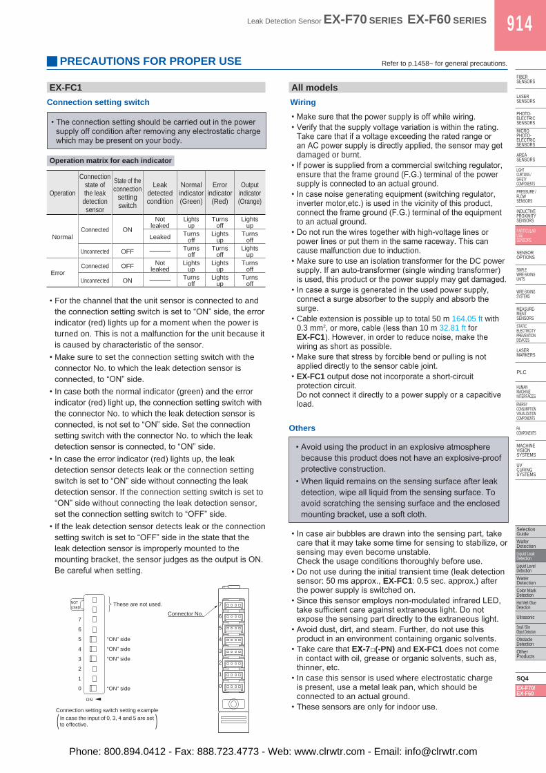
EX-FC1Connection setting switch
• The connection setting should be carried out in the powersupply off condition after removing any electrostatic chargewhich may be present on your body.
• For the channel that the unit sensor is connected to andthe connection setting switch is set to “ON” side, the errorindicator (red) lights up for a moment when the power isturned on. This is not a malfunction for the unit because itis caused by characteristic of the sensor.
• Make sure to set the connection setting switch with theconnector No. to which the leak detection sensor isconnected, to “ON” side.
• In case both the normal indicator (green) and the errorindicator (red) light up, the connection setting switch withthe connector No. to which the leak detection sensor isconnected, is not set to “ON” side. Set the connectionsetting switch with the connector No. to which the leakdetection sensor is connected, to “ON” side.
• In case the error indicator (red) lights up, the leakdetection sensor detects leak or the connection settingswitch is set to “ON” side without connecting the leakdetection sensor. If the connection setting switch is set to“ON” side without connecting the leak detection sensor,set the connection setting switch to “OFF” side.
• If the leak detection sensor detects leak or the connectionsetting switch is set to “OFF” side in the state that theleak detection sensor is improperly mounted to themounting bracket, the sensor judges as the output is ON.Be careful when setting.
All modelsWiring• Make sure that the power supply is off while wiring.• Verify that the supply voltage variation is within the rating.
Take care that if a voltage exceeding the rated range oran AC power supply is directly applied, the sensor may getdamaged or burnt.
• If power is supplied from a commercial switching regulator,ensure that the frame ground (F.G.) terminal of the powersupply is connected to an actual ground.
• In case noise generating equipment (switching regulator,inverter motor,etc.) is used in the vicinity of this product,connect the frame ground (F.G.) terminal of the equipmentto an actual ground.
• Do not run the wires together with high-voltage lines orpower lines or put them in the same raceway. This cancause malfunction due to induction.
• Make sure to use an isolation transformer for the DC powersupply. If an auto-transformer (single winding transformer)is used, this product or the power supply may get damaged.
• In case a surge is generated in the used power supply,connect a surge absorber to the supply and absorb thesurge.
• Cable extension is possible up to total 50 m 164.05 ft with0.3 mm2, or more, cable (less than 10 m 32.81 ft forEX-FC1). However, in order to reduce noise, make thewiring as short as possible.
• Make sure that stress by forcible bend or pulling is notapplied directly to the sensor cable joint.
• EX-FC1 output dose not incorporate a short-circuitprotection circuit.Do not connect it directly to a power supply or a capacitiveload.
( )
7
6
5
4
3
2
1
0
7
NOTUSED
6
5
4
3
2
1
0
ON
Connector No.
These are not used.
“ON” side
“ON” side
“ON” side
“ON” side
Connection setting switch setting exampleIn case the input of 0, 3, 4 and 5 are set to effective.
• In case air bubbles are drawn into the sensing part, takecare that it may take some time for sensing to stabilize, orsensing may even become unstable.Check the usage conditions thoroughly before use.
• Do not use during the initial transient time (leak detectionsensor: 50 ms approx., EX-FC1: 0.5 sec. approx.) afterthe power supply is switched on.
• Since this sensor employs non-modulated infrared LED,take sufficient care against extraneous light. Do notexpose the sensing part directly to the extraneous light.
• Avoid dust, dirt, and steam. Further, do not use thisproduct in an environment containing organic solvents.
• Take care that EX-7□(-PN) and EX-FC1 does not comein contact with oil, grease or organic solvents, such as,thinner, etc.
• In case this sensor is used where electrostatic chargeis present, use a metal leak pan, which should beconnected to an actual ground.
• These sensors are only for indoor use.
• Avoid using the product in an explosive atmospherebecause this product does not have an explosive-proofprotective construction.
• When liquid remains on the sensing surface after leakdetection, wipe all liquid from the sensing surface. Toavoid scratching the sensing surface and the enclosedmounting bracket, use a soft cloth.
Others
Operation matrix for each indicator
Refer to p.1458~ for general precautions.
Phone: 800.894.0412 - Fax: 888.723.4773 - Web: www.clrwtr.com - Email: [email protected]
915 Leak Detection Sensor EX-F70 SERIES EX-F60 SERIES
Selection GuideWafer
DetectionLiquid Leak
DetectionLiquid Level
DetectionWater
DetectionColor Mark
DetectionHot Melt Glue
Detection
Ultrasonic
Small / Slim Object Detection
Obstacle Detection
Other Products
SQ4EX-F70/EX-F60
FIBERSENSORS
LASERSENSORS
PHOTO-ELECTRICSENSORS
MICROPHOTO-
ELECTRICSENSORS
AREASENSORS
LIGHTCURTAINS /
SAFETYCOMPONENTS
PRESSURE / FLOW
SENSORS
INDUCTIVEPROXIMITY
SENSORS
PARTICULARUSE
SENSORS
SENSOROPTIONS
SIMPLEWIRE-SAVING
UNITS
WIRE-SAVING SYSTEMS
MEASURE-MENT
SENSORSSTATIC
ELECTRICITYPREVENTION
DEVICES
LASERMARKERS
PLC
HUMAN MACHINE
INTERFACESENERGY
CONSUMPTION VISUALIZATION COMPONENTS
FA COMPONENTS
MACHINE VISION
SYSTEMS
UV CURING
SYSTEMS
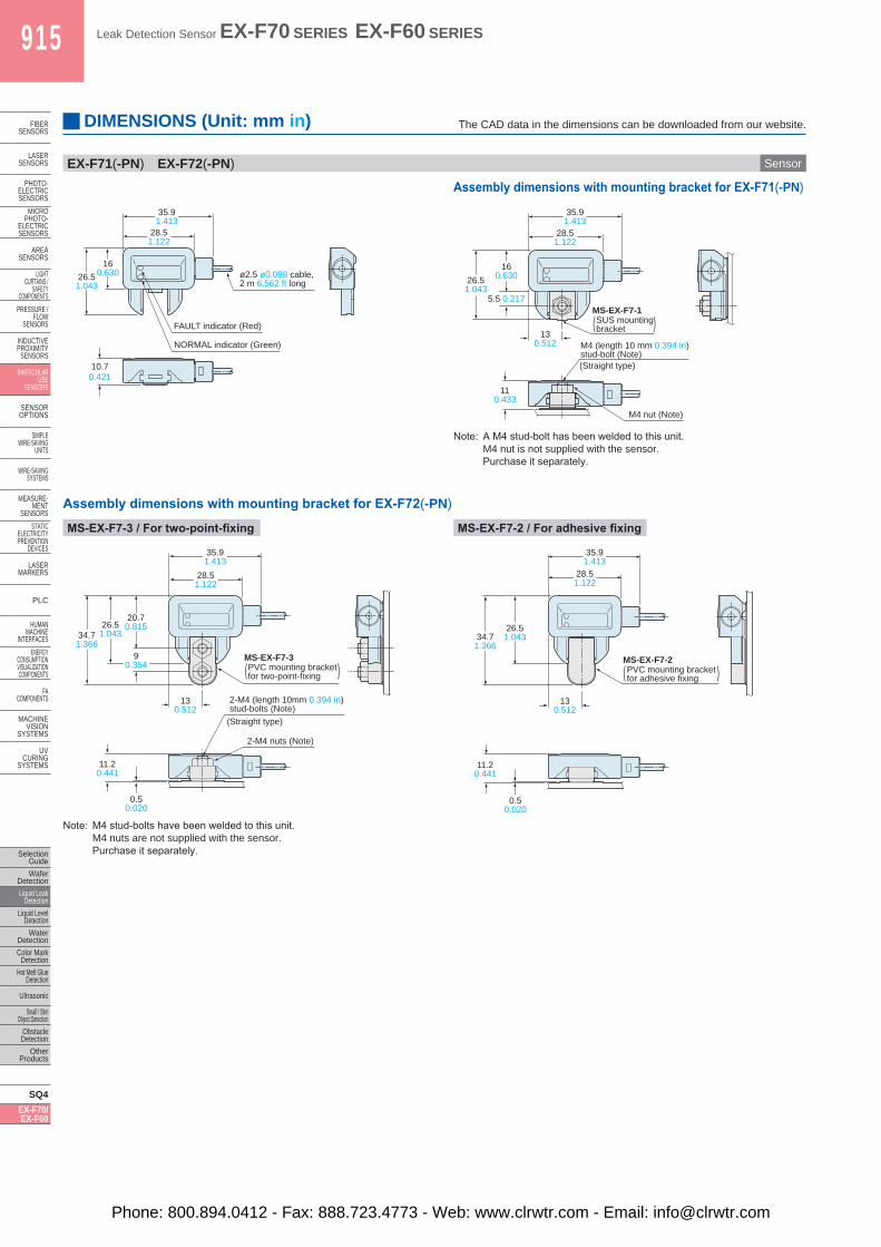
EX-F71(-PN) EX-F72(-PN) Sensor
Assembly dimensions with mounting bracket for EX-F71(-PN)
Assembly dimensions with mounting bracket for EX-F72(-PN)
MS-EX-F7-3 / For two-point-fixing MS-EX-F7-2 / For adhesive fixing
Note: A M4 stud-bolt has been welded to this unit.M4 nut is not supplied with the sensor.Purchase it separately.
Note: M4 stud-bolts have been welded to this unit.M4 nuts are not supplied with the sensor.Purchase it separately.
26.51.043
160.630
35.91.413
28.51.122
10.70.421
ø2.5 ø0.098 cable, 2 m 6.562 ft long
FAULT indicator (Red)
NORMAL indicator (Green)
28.51.122
160.63026.5
1.0435.5 0.217
130.512
110.433
35.91.413
(Straight type)
M4 (length 10 mm 0.394 in)stud-bolt (Note)
M4 nut (Note)
MS-EX-F7-1)(SUS mounting
bracket
26.51.043
0.50.020
35.91.413
28.51.122
34.71.366
90.354
20.70.815
11.20.441
130.512
2-M4 nuts (Note)
)(
(Straight type)
2-M4 (length 10mm 0.394 in)stud-bolts (Note)
PVC mounting bracketfor two-point-fixing
MS-EX-F7-3
26.51.043
0.50.020
35.91.413
28.51.122
34.71.366
11.20.441
130.512
MS-EX-F7-2)( PVC mounting bracket
for adhesive fixing
DIMENSIONS (Unit: mm in) The CAD data in the dimensions can be downloaded from our website.
Phone: 800.894.0412 - Fax: 888.723.4773 - Web: www.clrwtr.com - Email: [email protected]
Leak Detection Sensor EX-F70 SERIES EX-F60 SERIES 916
Selection GuideWafer DetectionLiquid Leak DetectionLiquid Level DetectionWater DetectionColor Mark DetectionHot Melt Glue Detection
Ultrasonic
Small / Slim Object DetectionObstacle DetectionOther Products
SQ4EX-F70/EX-F60
FIBERSENSORS
LASERSENSORS
PHOTO-ELECTRICSENSORSMICROPHOTO-ELECTRICSENSORS
AREASENSORS
LIGHTCURTAINS /SAFETYCOMPONENTSPRESSURE / FLOWSENSORS
INDUCTIVEPROXIMITYSENSORS
PARTICULARUSE SENSORS
SENSOROPTIONS
SIMPLEWIRE-SAVINGUNITS
WIRE-SAVING SYSTEMS
MEASURE-MENTSENSORSSTATIC ELECTRICITYPREVENTIONDEVICES
LASERMARKERS
PLC
HUMAN MACHINE INTERFACESENERGY CONSUMPTION VISUALIZATION COMPONENTS
FA COMPONENTS
MACHINE VISION SYSTEMS
UV CURING SYSTEMS
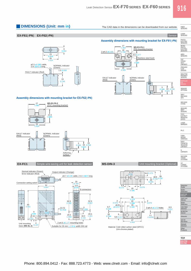
EX-F61(-PN) EX-F62(-PN) Sensor
Assembly dimensions with mounting bracket for EX-F61(-PN)
Assembly dimensions with mounting bracket for EX-F62(-PN)
EX-FC1 Simple wire-saving unit for leak detection sensor MS-DIN-3 Unit mounting bracket (Optional)
1.5 0.059
23 0.906
26 1.024
ø2.5 ø0.098 cable, 3 m 9.843 ft long NORMAL indicator
(Green)
FAULT indicator (Red)
19 0.748
9 0.354
3 0.188 14
0.551
19 0.748
FAULT indicator (Red)
NORMAL indicator (Green)
2-ø4.2 ø0.165 4.5 0.177
17 0.669
MS-EX-F6-1PFA mounting bracket
Stainless steel bush
18 0.709
27 1.063
26 1.024
Adhering surface
21.5 0.846
26 1.024
27 1.063
MS-EX-F6-2(PVC mounting bracket)
3 0.188 14
0.551
19 0.748
FAULT indicator (Red)
NORMAL indicator (Green)
(11.5)(0.453)
522.047
90.354
130.512
933.661
40.157
25.51.004
29.51.16118.3
0.720
14.60.575
200.787
7.5 0.295
52.52.067
60.52.382
Normal indicator (Green)Error indicator (Red)
Connection setting switch
Output indicator (Orange)
7
6
5
4
3
2
1
0401.575
ø3.7 ø0.146 cable, 2 m 6.562 ft long
2-ø4.5 ø0.177 mounting holesUnit mountingbase (MS-SL-2) Suitable for 35 mm 1.378 in width DIN rail
8 connectors
100.394
18.50.728
200.787
4.4 0.1732 0.079
150.591
150.591
ø1.8ø0.071
220.866
271.063
20.079
0.70.028
0.30.012
t 1t 0.039
20.079
351.378
5.5 0.217
4.40.173
20.079
2-ø4.4 ø0.173 holes
100.394
DIMENSIONS (Unit: mm in) The CAD data in the dimensions can be downloaded from our website.
Material: Cold rolled carbon steel (SPCC) (Uni-chrome plated)
Phone: 800.894.0412 - Fax: 888.723.4773 - Web: www.clrwtr.com - Email: [email protected]