Embed Size (px)
Citation preview
Panasonic Digital Business System - Programming ManualApril 1997 Issue 15
1
PanasonicDigital Business System
Programming Manual
Panasonic Digital Business System - Programming ManualApril 1997 Issue 15
2
Contents
HOW TO PROGRAM 3
OVERVIEW 3PROGRAMMING METHOD 3STORING ALPHA CHARACTERS IN THE MEMORY 5EXAMPLE OF PROGRAMMING 6
LIST OF PROGRAMMING FEATURES 7
SYSTEM FEATURES 7EXCHANGE LINE INTERFACE 10EXTENSION SETTING 11RINGING ASSIGNMENT 11FF KEY ASSIGNMENT 11STORING NAMES AND MESSAGES 11CALL BARRING 12COPY MODE 12SYSTEM SPEED DIAL MEMORY 12LCR 12
PROGRAMMING DETAILS 13
SYSTEM FEATURES 13EXCHANGE LINE INTERFACE 74EXTENSION FEATURES 89RINGING ASSIGNMENT 97FF KEY ASSIGNMENT 105STORING NAMES AND MESSAGES 107CALL BARRING 110COPY MODE 119SYSTEM SPEED DIAL MEMORY 121LCR 122
REMOTE PROGRAMMING 127
REMOTE PROGRAMMING OUTLINE 127STARTING REMOTE PROGRAMMING 128REMOTE PROGRAMMING MODES 128EFFECTIVE NUMBER OF DIGITS FOR INPUT 129COMPLETION OF REMOTE PROGRAMMING 129REMOTE PROGRAMMING DISPLAY - SAMPLE 129
Panasonic Digital Business System - Programming ManualApril 1997 Issue 15
3
How To Program
Overview
DBS programming is carried out from an operator telephone (connected to extension port 1) or aspecially enabled display keyset. This manual assumes that programming will be performed fromthe operator telephone , extension 200 connected to extension port 1.
After loading the default program, not all system features will be available. Therefore the systemmust be programmed to the users requirements.
Any programming changes from initial set must be recorded in the programming table formaintenance purposes.
Some programming features will require the system to be reset by switching it off and back on.This will cause the CPU to re-read the system’s programmed settings and adjust system operationaccordingly.
Programming method
Loading Default Data
The following procedure loads the default data settings.
1) Assure the RAM switch on the CPC card is set to the RAMCLR position.2) Switch ON the main unit. The LED Data lamp (Red) on the CPC card flickers for
between 10 and 20 seconds then goes out. The default settings are now loaded.3) Put the RAM switch to the HOLD side. Default data is protected in memory. Data lamp
flashes continuously.
The system will not function with the RAM switch in the RAMCLR position. Programming changesare made with RAM switch in the HOLD position.
Initialising The CPC-EX Card
Before programming the CPC-EX card it must be initialised in the same way as previous CPCcards, plus the system size and number of analogue line cards ( including private circuit cards )must be set so that the ports are powered up correctly. Use the DASSII steps FF1 6# 1# 1# & FF16# 1# 2# to do this.
Panasonic Digital Business System - Programming ManualApril 1997 Issue 15
4
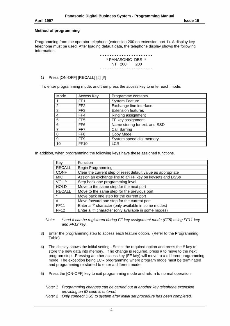
Method of programming
Programming from the operator telephone (extension 200 on extension port 1). A display keytelephone must be used. After loading default data, the telephone display shows the followinginformation,
- - - - - - - - - - - - - - - - - - - - - -* PANASONIC DBS *
INT 200 200- - - - - - - - - - - - - - - - - - - - - -
1) Press [ON-OFF] [RECALL] [#] [#]
To enter programming mode, and then press the access key to enter each mode.
Mode Access Key Programme contents.1 FF1 System Feature2 FF2 Exchange line interface3 FF3 Extension features4 FF4 Ringing assignment5 FF5 FF key assignment6 FF6 Name storing for ext. and SSD7 FF7 Call Barring8 FF8 Copy Mode9 FF9 System speed dial memory10 FF10 LCR
In addition, when programming the following keys have these assigned functions.
Key FunctionRECALL Begin ProgrammingCONF Clear the current step or reset default value as appropriateMIC Assign an exchange line to an FF key on keysets and DSSsVOL ^ Step back one programming levelHOLD Move to the same step for the next portRECALL Move to the same step for the previous port* Move back one step for the current port# Move forward one step for the current portFF11 Enter a ‘*’ character (only available in some modes)FF12 Enter a ‘#’ character (only available in some modes)
Note: * and # can be registered during FF key assignment mode (FF5) using FF11 keyand FF12 key.
3) Enter the programming step to access each feature option. (Refer to the ProgrammingTable)
4) The display shows the initial setting. Select the required option and press the # key tostore the new data into memory. If no change is required, press # to move to the nextprogram step. Pressing another access key (FF key) will move to a different programmingmode. The exception being LCR programming where program mode must be terminatedand programming re started to enter a different mode.
5) Press the [ON-OFF] key to exit programming mode and return to normal operation.
Note: 1 Programming changes can be carried out at another key telephone extensionproviding an ID code is entered.
Note: 2 Only connect DSS to system after initial set procedure has been completed.
Panasonic Digital Business System - Programming ManualApril 1997 Issue 15
5
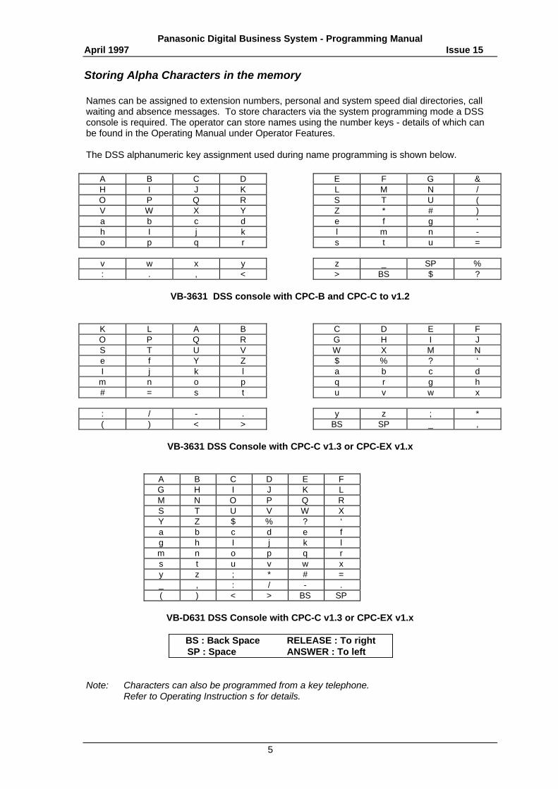
Storing Alpha Characters in the memory
Names can be assigned to extension numbers, personal and system speed dial directories, callwaiting and absence messages. To store characters via the system programming mode a DSSconsole is required. The operator can store names using the number keys - details of which canbe found in the Operating Manual under Operator Features.
The DSS alphanumeric key assignment used during name programming is shown below.
A B C D E F G &H I J K L M N /O P Q R S T U (V W X Y Z * # )a b c d e f g ‘h I j k l m n -o p q r s t u =
v w x y z _ SP %: . , < > BS $ ?
VB-3631 DSS console with CPC-B and CPC-C to v1.2
K L A B C D E FO P Q R G H I JS T U V W X M Ne f Y Z $ % ? ‘I j k l a b c d
m n o p q r g h# = s t u v w x
: / - . y z ; *( ) < > BS SP _ ,
VB-3631 DSS Console with CPC-C v1.3 or CPC-EX v1.x
A B C D E FG H I J K LM N O P Q RS T U V W XY Z $ % ? ‘a b c d e fg h I j k lm n o p q rs t u v w xy z ; * # =_ , : / - .( ) < > BS SP
VB-D631 DSS Console with CPC-C v1.3 or CPC-EX v1.x
BS : Back Space RELEASE : To rightSP : Space ANSWER : To left
Note: Characters can also be programmed from a key telephone.Refer to Operating Instruction s for details.
Panasonic Digital Business System - Programming ManualApril 1997 Issue 15
6
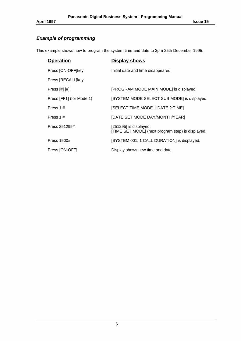
Example of programming
This example shows how to program the system time and date to 3pm 25th December 1995.
Operation Display shows
Press [ON-OFF]key Initial date and time disappeared.
Press [RECALL]key
Press [#] [#] [PROGRAM MODE MAIN MODE] is displayed.
Press [FF1] (for Mode 1) [SYSTEM MODE SELECT SUB MODE] is displayed.
Press 1 # [SELECT TIME MODE 1:DATE 2:TIME]
Press 1 # [DATE SET MODE DAY/MONTH/YEAR]
Press 251295# [251295] is displayed.[TIME SET MODE] (next program step) is displayed.
Press 1500# [SYSTEM 001: 1 CALL DURATION] is displayed.
Press [ON-OFF]. Display shows new time and date.
Panasonic Digital Business System - Programming ManualApril 1997 Issue 15
7
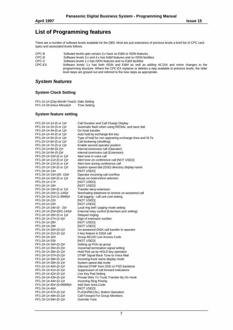
LLiisstt ooff PPrrooggrraammmmiinngg ffeeaattuurreess
There are a number of software levels available for the DBS. Most are just extensions of previous levels a breif list of CPC cardtypes and associated levels follows.
CPC-B Software levels upto version 3.x have no E&M or ISDN featuresCPC-B Software levels 3.x and 4.x has E&M features and no ISDN facilitiesCPC-C Software levels 1.x has ISDN features and no E&M facilitiesCPC-EX Software levels 1.x has both ISDN and E&M as well as adding AC15A and minor changes to the
programming structure. Where the CPC-EX replaces or deletes a step available to previous levels, the olderlevel steps are greyed out and referred to the new steps as appropriate.
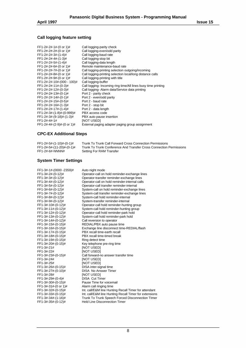
System features
System Clock Setting
FF1-1#-1#-(Day-Month-Year)# Date SettingFF1-1#-2#-(Hour-Minute)# Time Setting
System feature setting
FF1-2#-1#-1#-(0 or 1)# Call Duration and Call Charge DisplayFF1-2#-1#-2#-(0 or 1)# Automatic flash when using REDIAL and save dialFF1-2#-1#-3#-(0 or 1)# On hook transferFF1-2#-1#-4#-(0 or 1)# Auto hold by exchange line keyFF1-2#-1#-5#-(0 or 1)# Type of hold for non appearing exchange lines and SLTsFF1-2#-1#-6#-(0 or 1)# Call brokering (shuttling)FF1-2#-1#-7#-(0 or 1)# Enable second operator positionFF1-2#-1#-8#-(0-2)# Internal tone/voice call (Operator)FF1-2#-1#-9#-(0-2)# Internal tone/voice call (Extension)FF1-2#-1#-10#-(0 or 1)# Alert tone in voice callFF1-2#-1#-11#-(0 or 1)# Alert tone on conference call [NOT USED]FF1-2#-1#-12#-(0 or 1)# Alert tone during conference callFF1-2#-1#-13#-(0 or 1)# System speed dial (SSD) directory display-nameFF1-2#-1#-14# [NOT USED]FF1-2#-1#-15#-(00 -15)# Operator incoming call overflowFF1-2#-1#-16#-(0 or 1)# Music-on-hold-int/ext selectionFF1-2#-1#-17# [NOT USED]FF1-2#-1#-18# [NOT USED]FF1-2#-1#-19#-(0 or 1)# Transfer deny-extensionFF1-2#-1#-20#-(1-144)# Nominating telephone to receive un-answered callFF1-2#-1#-21#-(1-9999)# Call logging - call unit cost settingFF1-2#-1#-22# [NOT USED]FF1-2#-1#-23# [NOT USED]FF1-2#-1#-24#-(0 - 2)# Loud ring bell / paging mode settingFF1-2#-1#-25#-(001-144)# External relay control (Extension port setting)FF1-2#-1#-26#-(0 or 1)# Delayed ringingFF1-2#-1#-27#-(2-4)# Digit of extension numberFF1-2#-1#-28# [NOT USED]FF1-2#-1#-29# [NOT USED]FF1-2#-1#-30#-(0-1)# Un-answered DISA call transfer to operatorFF1-2#-1#-31#-(0-1)# # key feature in DISA callFF1-2#-1#-32# Group MCO0 Line Access CodeFF1-2#-1#-33# [NOT USED]FF1-2#-1#-34#-(0-2)# Setting up Pick-up groupFF1-2#-1#-35#-(0-2)# Voicemail termination signal settingFF1-2#-1#-36#-(0-1)# Hold Pick-up by HOLD key operationFF1-2#-1#-37#-(0-2)# DTMF Signal Back Tone to Voice MailFF1-2#-1#-38#-(0-1)# Incoming trunk name display modeFF1-2#-1#-39#-(0-1)# System speed dial modeFF1-2#-1#-40#-(0-1)# Internal DTMF from SSD or PSD backtoneFF1-2#-1#-41#-(0-1)# Suppression of call forward indicationsFF1-2#-1#-42#-(0-1)# Live Key Pad SettingFF1-2#-1#-43#-(0-1)# Private Wire To Trunk Transfer By On HookFF1-2#-1#-44#-(0-1)# Incoming Ring PriorityFF1-2#-1#-45#-(0-09999)# Add Own Area CodeFF1-2#-1#-46# [NOT USED]FF1-2#-1#-47#-(0-1)# FLASH/RECALL Button OperationFF1-2#-1#-48#-(0-1)# Call Forward For Group MembersFF1-2#-1#-94#-(0-1)# Override Tone
Panasonic Digital Business System - Programming ManualApril 1997 Issue 15
8
Call logging feature setting
FF1-2#-2#-1#-(0 or 1)# Call logging-parity checkFF1-2#-2#-2#-(0 or 1)# Call logging-even/odd parityFF1-2#-2#-3#-(1-4)# Call logging-baud rateFF1-2#-2#-4#-(1-3)# Call logging-stop bitFF1-2#-2#-5#-(1-4)# Call logging-data lengthFF1-2#-2#-6#-(0 or 1)# Remote maintenance-baud rateFF1-2#-2#-7#-(0 or 1)# Call logging-printing selection outgoing/incomingFF1-2#-2#-8#-(0 or 1)# Call logging-printing selection local/long distance callsFF1-2#-2#-9#-(0 or 1)# Call logging-printing with titleFF1-2#-2#-10#-(000 - 100)# Call logging-bufferFF1-2#-2#-11#-(0-3)# Call logging- Incoming ring time/All lines busy time printingFF1-2#-2#-12#-(0-3)# Call logging- Alarm data/Service data printingFF1-2#-2#-13#-(0-1)# Port 2 - parity checkFF1-2#-2#-14#-(0-1)# Port 2 - even/odd parityFF1-2#-2#-15#-(0-5)# Port 2 - baud rateFF1-2#-2#-16#-(1-3)# Port 2 - stop bitFF1-2#-2#-17#-(1-4)# Port 2 - data lengthFF1-2#-3#-(1-8)#-(0-999)# PBX access codeFF1-2#-3#-(9-18)#-(1-3)# PBX auto pause insertionFF1-2#-4#-1# [NOT USED]FF1-2#-4#-(2-9)#-(0 or 1)# External paging adapter paging group assignment
CPC-EX Additional Steps
FF1-2#-5#-(1-10)#-(0-1)# Trunk To Trunk Call Forward Cross Connection PermissionsFF1-2#-5#-(11-20)#-(0-1)# Trunk To Trunk Conference And Transfer Cross Connection PermissionsFF1-2#-6#-NNNN# Setting For RAM Transfer
System Timer Settings
FF1-3#-1#-(0000 -2359)# Auto night modeFF1-3#-2#-(0-12)# Operator-call on hold reminder-exchange linesFF1-3#-3#-(0-12)# Operator-transfer reminder-exchange linesFF1-3#-4#-(0-12)# Operator-call on hold reminder-internal callsFF1-3#-5#-(0-12)# Operator-call transfer reminder-internalFF1-3#-6#-(0-12)# System-call on hold reminder-exchange linesFF1-3#-7#-(0-12)# System-call transfer reminder-exchange linesFF1-3#-8#-(0-12)# System-call hold reminder-internalFF1-3#-9#-(0-12)# System-transfer reminder-internalFF1-3#-10#-(0-12)# Operator-call hold reminder-hunting groupFF1-3#-11#-(0-12)# System-call hold reminder-hunting groupFF1-3#-12#-(0-12)# Operator-call hold reminder-park holdFF1-3#-13#-(0-12)# System-call hold reminder-park holdFF1-3#-14#-(0-12)# Call reversion to operatorFF1-3#-15#-(0-15)# REDIAL/PBX auto pause timeFF1-3#-16#-(0-15)# Exchange line disconnect time-REDIAL/flashFF1-3#-17#-(0-15)# PBX recall time-earth recallFF1-3#-18#-(0-15)# PBX recall time-timed breakFF1-3#-19#-(0-15)# Ring detect timeFF1-3#-20#-(0-15)# Key telephone pre-ring timeFF1-3#-21# [NOT USED]FF1-3#-22# [NOT USED]FF1-3#-23#-(0-15)# Call forward-no answer transfer timeFF1-3#-24# [NOT USED]FF1-3#-25# [NOT USED]FF1-3#-26#-(0-15)# DISA inter-signal timeFF1-3#-27#-(0-10)# DISA No Answer TimerFF1-3#-28# [NOT USED]FF1-3#-29#-(0-4)# DISA Cut TimerFF1-3#-30#-(0-15)# Pause Time for voicemailFF1-3#-31#-(0 or 1)# Alarm call ringing timeFF1-3#-32#-(0-15)# Int. call/E&M line Hunting Recall Timer for attendantFF1-3#-33#-(0-15)# Int. call/E&M line Hunting Recall Timer for extensionsFF1-3#-34#-(1-16)# Trunk To Trunk Speech Forced Disconnection TImerFF1-3#-35#-(0-12)# Held Line Disconnection Timer
Panasonic Digital Business System - Programming ManualApril 1997 Issue 15
9
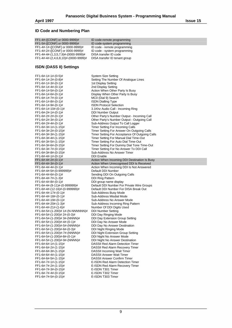
ID Code and Numbering Plan
FF1-4#-([CONF] or 0000-9999)# ID code-remote programmingFF1-5#-([CONF] or 0000-9999)# ID code-system programmingFF1-4#-1#-([CONF] or 0000-9999)# ID code - remote programmingFF1-4#-2#-([CONF] or 0000-9999)# ID code - system programmingFF1-4#-4#-(1,3,5,7,9)#-(0000-9999)# DISA transfer ID codeFF1-4#-4#-(2,4,6,8,10)#-(0000-9999)# DISA transfer ID tenant group
ISDN (DASS II) Settings
FF1-6#-1#-1#-(0-5)# System Size SettingFF1-6#-1#-2#-(0-8)# Setting The Number Of Analogue LinesFF1-6#-1#-3#-(0-1)# 1st Display SettingFF1-6#-1#-4#-(0-1)# 2nd Display SettingFF1-6#-1#-5#-(0-1)# Action When Other Party Is BusyFF1-6#-1#-6#-(0-1)# Display When Other Party Is BusyFF1-6#-1#-7#-(0-1)# MC0 (Dial 9) SearchFF1-6#-1#-8#-(0-1)# ISDN Dialling TypeFF1-6#-1#-9#-(0-1)# ISDN Protocol SelectionFF1-6#-1#-10#-(0-1)# 3.1Khz Audio Call - Incoming RingFF1-6#-2#-1#-(0-1)# DDI Number OutputFF1-6#-2#-2#-(0-1)# Other Party’s Number Output - Incoming CallFF1-6#-2#-3#-(0-1)# Other Party’s Number Output - Outgoing CallFF1-6#-2#-4#-(0-1)# Sub-Address Output To Call LoggerFF1-6#-3#-1#-(1-15)# Timer Setting For Incoming CallsFF1-6#-3#-2#-(0-15)# Timer Setting For Answer On Outgoing CallsFF1-6#-3#-3#-(1-15)# Timer Setting For Acceptance Of Outgoing CallsFF1-6#-3#-4#-(1-15)# Timer Setting For Manual Dial Time-OutFF1-6#-3#-5#-(1-15)# Timer Setting For Auto Dial Time-OutFF1-6#-3#-6#-(0-15)# Timer Setting For Dummy Dial Tone Time-OutFF1-6#-3#-7#-(0-15)# Timer Setting For No Answer To DDI CallFF1-6#-3#-8#-(0-15)# Sub-Address No Answer TimerFF1-6#-4#-1#-(0-1)# DDI EnableFF1-6#-4#-2#-(0-1)# Action When Incoming DDI Destination Is BusyFF1-6#-4#-3#-(0-1)# Action When Unrecognised DDI Is ReceivedFF1-6#-4#-4#-(0-1)# Action When Incoming DDI Is Not AnsweredFF1-6#-4#-5#-(0-999999)# Default DDI NumberFF1-6#-4#-6#-(0-1)# Sending DDI On Outgoing CallsFF1-6#-4#-7#-(1-3)# DDI Ring PatternFF1-6#-4#-8#-(0-1)# DDI group name display FF1-6#-4#-(9-11)#-(0-999999)# Default DDI Number For Private Wire GroupsFF1-6#-4#-(12-16)#-(0-999999)# Default DDI Number For DISA Break OutFF1-6#-4#-17#-(0-1)# Sub-Address Busy ModeFF1-6#-4#-18#-(0-1)# Sub-Address Misdial ModeFF1-6#-4#-19#-(0-1)# Sub-Address No Answer ModeFF1-6#-4#-20#-(1-3)# Sub-Address Incoming Ring PatternFF1-6#-4#-21#-(1-6)# Number Of DDI Digits UsedFF1-6#-5#-(1-200)# 1#-(N-NNNNNN)# DDI Number SettingFF1-6#-5#-(1-200)# 2#-(0-3)# DDI Day Ringing ModeFF1-6#-5#-(1-200)# 3#-(NNNN)# DDI Day Extension Group SettingFF1-6#-5#-(1-200)#-4#-(0-1)# DDI Day No Answer ModeFF1-6#-5#-(1-200)#-5#-(NNNN)# DDI Day No Answer DestinationFF1-6#-5#-(1-200)#-6#-(0-3)# DDI Night Ringing ModeFF1-6#-5#-(1-200)#-7#-(NNNN)# DDI Night Extension Group SettingFF1-6#-5#-(1-200)#-8#-(0-1)# DDI Night No Answer ModeFF1-6#-5#-(1-200)#-9#-(NNNN)# DDI Night No Answer DestinationFF1-6#-6#-1#-(1-15)# DASSII Red Alarm Detection TimerFF1-6#-6#-2#-(1-15)# DASSII Red Alarm Recovery TimerFF1-6#-6#-3#-(1-15)# DASSII Incoming Wait TimerFF1-6#-6#-4#-(1-15)# DASSII Answer Wait TimerFF1-6#-6#-5#-(1-15)# DASSII Answer Confirm TimerFF1-6#-7#-1#-(1-15)# E-ISDN Red Alarm Detection TimerFF1-6#-7#-2#-(1-15)# E-ISDN Red Alarm Recovery TimerFF1-6#-7#-3#-(0-15)# E-ISDN T301 TimerFF1-6#-7#-4#-(0-15)# E-ISDN T302 TimerFF1-6#-7#-5#-(0-15)# E-ISDN T303 Timer
Panasonic Digital Business System - Programming ManualApril 1997 Issue 15
10
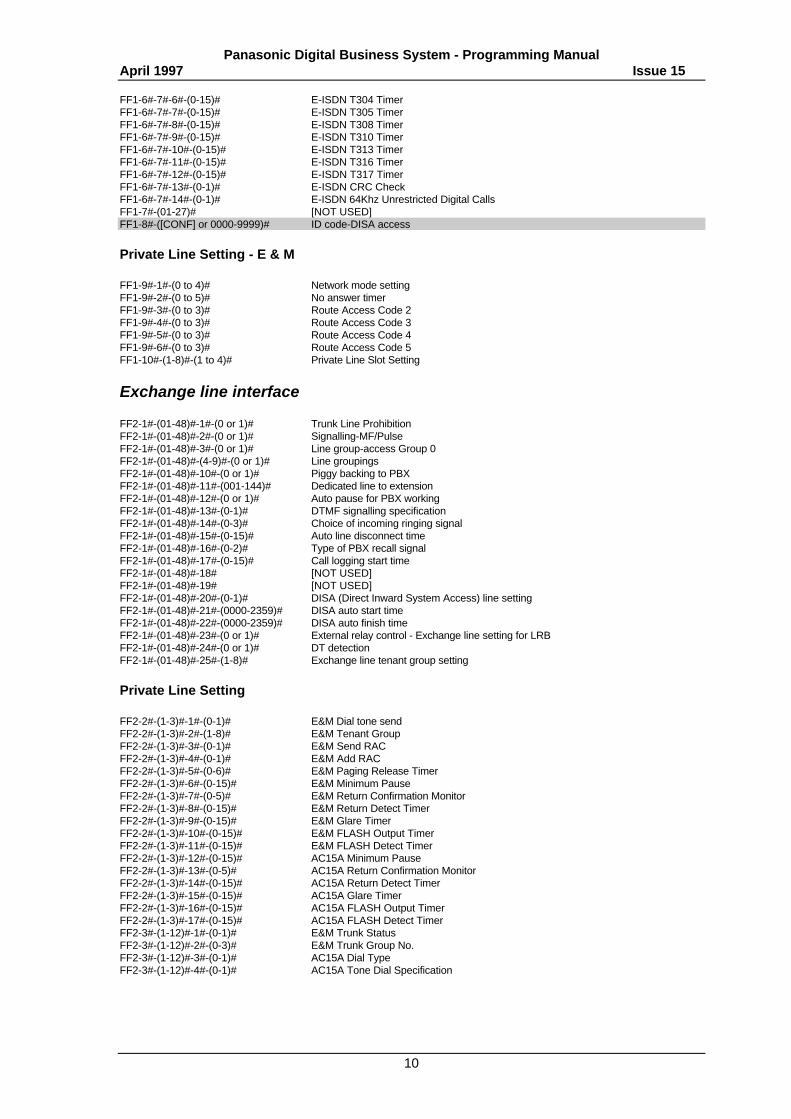
FF1-6#-7#-6#-(0-15)# E-ISDN T304 TimerFF1-6#-7#-7#-(0-15)# E-ISDN T305 TimerFF1-6#-7#-8#-(0-15)# E-ISDN T308 TimerFF1-6#-7#-9#-(0-15)# E-ISDN T310 TimerFF1-6#-7#-10#-(0-15)# E-ISDN T313 TimerFF1-6#-7#-11#-(0-15)# E-ISDN T316 TimerFF1-6#-7#-12#-(0-15)# E-ISDN T317 TimerFF1-6#-7#-13#-(0-1)# E-ISDN CRC CheckFF1-6#-7#-14#-(0-1)# E-ISDN 64Khz Unrestricted Digital CallsFF1-7#-(01-27)# [NOT USED]FF1-8#-([CONF] or 0000-9999)# ID code-DISA access
Private Line Setting - E & M
FF1-9#-1#-(0 to 4)# Network mode settingFF1-9#-2#-(0 to 5)# No answer timerFF1-9#-3#-(0 to 3)# Route Access Code 2FF1-9#-4#-(0 to 3)# Route Access Code 3FF1-9#-5#-(0 to 3)# Route Access Code 4FF1-9#-6#-(0 to 3)# Route Access Code 5FF1-10#-(1-8)#-(1 to 4)# Private Line Slot Setting
Exchange line interface
FF2-1#-(01-48)#-1#-(0 or 1)# Trunk Line ProhibitionFF2-1#-(01-48)#-2#-(0 or 1)# Signalling-MF/PulseFF2-1#-(01-48)#-3#-(0 or 1)# Line group-access Group 0FF2-1#-(01-48)#-(4-9)#-(0 or 1)# Line groupingsFF2-1#-(01-48)#-10#-(0 or 1)# Piggy backing to PBXFF2-1#-(01-48)#-11#-(001-144)# Dedicated line to extensionFF2-1#-(01-48)#-12#-(0 or 1)# Auto pause for PBX workingFF2-1#-(01-48)#-13#-(0-1)# DTMF signalling specificationFF2-1#-(01-48)#-14#-(0-3)# Choice of incoming ringing signalFF2-1#-(01-48)#-15#-(0-15)# Auto line disconnect timeFF2-1#-(01-48)#-16#-(0-2)# Type of PBX recall signalFF2-1#-(01-48)#-17#-(0-15)# Call logging start timeFF2-1#-(01-48)#-18# [NOT USED]FF2-1#-(01-48)#-19# [NOT USED]FF2-1#-(01-48)#-20#-(0-1)# DISA (Direct Inward System Access) line settingFF2-1#-(01-48)#-21#-(0000-2359)# DISA auto start timeFF2-1#-(01-48)#-22#-(0000-2359)# DISA auto finish timeFF2-1#-(01-48)#-23#-(0 or 1)# External relay control - Exchange line setting for LRBFF2-1#-(01-48)#-24#-(0 or 1)# DT detectionFF2-1#-(01-48)#-25#-(1-8)# Exchange line tenant group setting
Private Line Setting
FF2-2#-(1-3)#-1#-(0-1)# E&M Dial tone sendFF2-2#-(1-3)#-2#-(1-8)# E&M Tenant GroupFF2-2#-(1-3)#-3#-(0-1)# E&M Send RACFF2-2#-(1-3)#-4#-(0-1)# E&M Add RACFF2-2#-(1-3)#-5#-(0-6)# E&M Paging Release TimerFF2-2#-(1-3)#-6#-(0-15)# E&M Minimum PauseFF2-2#-(1-3)#-7#-(0-5)# E&M Return Confirmation MonitorFF2-2#-(1-3)#-8#-(0-15)# E&M Return Detect TimerFF2-2#-(1-3)#-9#-(0-15)# E&M Glare TimerFF2-2#-(1-3)#-10#-(0-15)# E&M FLASH Output TimerFF2-2#-(1-3)#-11#-(0-15)# E&M FLASH Detect TimerFF2-2#-(1-3)#-12#-(0-15)# AC15A Minimum PauseFF2-2#-(1-3)#-13#-(0-5)# AC15A Return Confirmation MonitorFF2-2#-(1-3)#-14#-(0-15)# AC15A Return Detect TimerFF2-2#-(1-3)#-15#-(0-15)# AC15A Glare TimerFF2-2#-(1-3)#-16#-(0-15)# AC15A FLASH Output TimerFF2-2#-(1-3)#-17#-(0-15)# AC15A FLASH Detect TimerFF2-3#-(1-12)#-1#-(0-1)# E&M Trunk StatusFF2-3#-(1-12)#-2#-(0-3)# E&M Trunk Group No.FF2-3#-(1-12)#-3#-(0-1)# AC15A Dial TypeFF2-3#-(1-12)#-4#-(0-1)# AC15A Tone Dial Specification
Panasonic Digital Business System - Programming ManualApril 1997 Issue 15
11
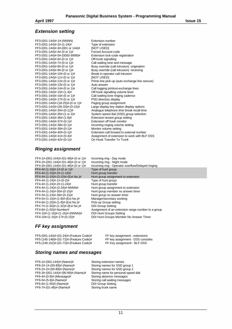
Extension setting
FF3-(001-144)#-1#-(NNNN) Extension numberFF3-(001-144)#-2#-(1-24)# Type of extensionFF3-(001-144)#-3#-(001 or 144)# [NOT USED]FF3-(001-144)#-4#-(0 or 1)# Forced Account codeFF3-(001-144)#-5#-(0000-9999)# Extension lock-code registrationFF3-(001-144)#-6#-(0 or 1)# Off-hook signallingFF3-(001-144)#-7#-(0 or 1)# Call waiting tone and messageFF3-(001-144)#-8#-(0 or 1)# Busy override (call intrusion) -originationFF3-(001-144)#-9#-(0 or 1)# Busy override (call intrusion) -receivingFF3-(001-144)#-10#-(0 or 1)# Break in-operator call intrusionFF3-(001-144)#-11#-(0 or 1)# [NOT USED]FF3-(001-144)#-12#-(0 or 1)# Prime line pick-up (auto exchange line seizure)FF3-(001-144)#-13#-(0 or 1)# Auto answerFF3-(001-144)#-14#-(0 or 1)# Call logging printout-exchange linesFF3-(001-144)#-15#-(1-4)# Off-hook signalling volume levelFF3-(001-144)#-16#-(0 or 1)# Call waiting tone ringing cadenceFF3-(001-144)#-17#-(0 or 1)# PSD directory displayFF3-(001-144)#-(18-25)#-(0 or 1)# Paging group assignmentFF3-(001-144)#-(26-33)#-(0-15)# Large display key station display optionsFF3-(001-144)#-34#-(0-12)# Analogue telephone time break recall timeFF3-(001-144)#-35#-(1 or 2)# System speed dial (SSD) group selectionFF3-(001-144)#-36#-(1-8)# Extension tenant group settingFF3-(001-144)#-37#-(0-1)# Extension off hook monitorFF3-(001-144)#-38#-(0-1)# Incoming ringing volume settingFF3-(001-144)#-39#-(0-1)# Monitor volume settingFF3-(001-144)#-40#-(0-1)# Extension call forward to external numberFF3-(001-144)#-41#-(0-4)# Assignment of extension to work with BLF DSSFF3-(001-144)#-42#-(0-1)# On Hook Transfer To Trunk
Ringing assignment
FF4-1#-(001-144)#-(01-48)#-(0 or 1)# Incoming ring - Day modeFF4-2#-(001-144)#-(01-48)#-(0 or 1)# Incoming ring - Night modeFF4-3#-(001-144)#-(01-48)#-(0 or 1)# Incoming ring - Operator overflow/Delayed ringingFF4-4#-(1-16)#-1#-(0 or 1)# Type of hunt groupFF4-4#-(1-16)#-2#-(1-16)# Hunt group transferFF4-4#-(1-16)#-(3-10)#-(Ext No.)# Hunt group assignment to extensionFF4-4#-(1-24)#-1#-(0-2)# Type of hunt groupFF4-4#-(1-24)#-2#-(1-24)# Hunt group transferFF4-4#-(1-24)#-(3-34)#-NNNN# Hunt group assignment to extensionFF4-4#-(1-24)#-35#-(0-15)# Hunt group member no answer timerFF4-4#-(1-24)#-36#-(0-15)# Hunt group no answer timerFF4-5#-(1-16)#-(1-8)#-(Ext No.)# Manager/secretary workingFF4-6#-(1-20)#-(1-8)#-(Ext No.)# Pick-up Group settingFF4 7#-(1-50)#-(1-32)#-(Ext No.)# DDI Group SettingFF4-8#-(1-50)#-Number# Assignment of an extension range number to a groupFF4-10#-(1-16)#-(1-16)#-(NNNN)# DDI Hunt Groups SettingFF4-10#-(1-16)#-17#-(0-15)# DDI Hunt Groups Member No Answer Timer
FF key assignment
FF5-(001-144)#-(01-24)#-(Feature Code)# FF key assignment - extensionsFF5-(145-148)#-(01-72)#-(Feature Code)# FF key assignment - DSS consolesFF5-(149-152)#-(01-72)#-(Feature Code)# FF Key assignment - BLF DSS
Storing names and messages
FF6-1#-(001-144)#-(Name)# Storing extension namesFF6-2#-1#-(00-89)#-(Name)# Storing names for SSD group 1FF6-2#-2#-(00-89)#-(Name)# Storing names for SSD group 2FF6-3#-(001-144)#-(90-99)#-(Name)# Storing name for personal speed dialFF6-4#-(0-9)#-(Message)# Storing absence messagesFF6-5#-(5-9)#-(Name)# Storing call waiting messagesFF6-6#-(1-50)#-(Name)# DDI Group SettingFF6-7#-(01-48)#-(Name)# Storing trunk name
Panasonic Digital Business System - Programming ManualApril 1997 Issue 15
12
Call barring
FF7-1#-1#-(0-9)# First digit for STD national callFF7-1#-2#-(0-9999)# Code for international diallingFF7-1#-3#-(0-9)# First digit for operator serviceFF7-1#-4#-(0 or 1)# Dialling restriction on incoming lineFF7-1#-5#-(0,3,4)# Digit restrictions - Special NumberFF7-(6-8)#-(0 or 3-15)# Digit restrictions - Local CallFF7-(9-10)#-(0 or 3-30)# Digit restrictions - Long Distance CallFF7-(11-13)#-(0 or 3-15)# Digit restrictions - Operator ServiceFF7-1#-(14-15)#-(0 or 1)# Local Call Dial RestrictionFF7-1#-17#-(0-5)# Extension class of service when lockedFF7-1#-18#-(00-89)# Restriction override using SSD code in group 1FF7-1#-19#-(00-89)# Restriction override using SSD code in group 2FF7-1#-(20-21)#-(0 or 1)# * restrictionFF7-1#-(22-23)#-(0 or 1)# # RestrictionFF7-1#-24#-(0-9)# 2nd digit of STD codeFF7-2#-(1-8)#-(000-999)# Storing 8 special service numbers (999 etc.)FF7-3#-(1-50)#-(0-99999999)# Local Call Dial RestrictionFF7-4#-(1-144)#-(01-48, 49)#-(1-5)# Class of service-day modeFF7-5#-(1-144)#-(01-48, 49)#-(1-5)# Class of service-night modeFF7-6#-(1-3)#-(0-999)#-(0 or 1)# Call barring look up table - operator serviceFF7-7#-(1-2)#-(0-999)#-(0 or 1)# Call barring look up table - STD nationalFF7-7#-3#-(1-16)#-(000-999)# Long Distance Call Restriction OverrideFF7-7#-(4-6)#-(1-32)#-(0-9999)# Restriction OverridesFF7-8#-(0-999)#-(0 or 1)# Call barring look up table - international callsFF7-9#-(1-144)#-(0 or 1)# SSD restriction overrideFF7-10#-1#-(1 to 3)#-(1 to 48)#-(1 to 5)# Setting the Daytime Private Line Restriction classFF7-10#-2#-(1 to 3)#-(1 to 48)#-(1 to 5)# Setting the Night-time Private Line Restriction class
Copy mode
FF8-1#-(01-48)#-(01-48)## Exchange line settingFF8-2#-(001-144)#-(001-144)## Extension settingFF8-3#-(001-144)#-(001-144)## FF (programmable) key settingFF8-4#-(1-2)#-(00-89)#-(00-89)## SSD group membersFF8-5#-(001-144)#-(001-144)## Personal speed dial
System speed dial memory
FF9-1#-1#-(0-89)#-(DIAL)# System speed dial group 1FF9-1#-2#-(0-89)#-(DIAL)# System speed dial group 2FF9-2#-(001-144)#-(90-99)#-(DIAL)# Personal speed dial
LCR
FF10-(Password)#-1#-1#-(0 or 1)# Use of LCRFF10-(Password)#-1#-2#-(0000-9999)# LCR programming passwordFF10-(Password)#-1#-3#-(1-15)# Pause after network access codeFF10-(Password)#-1#-(4-10)#-(0 or 1)# Registration of network carriersFF10-(Password)#-2#-(1-48)#-(1-7)#-(0 or 1)# Assignment of network operators to linesFF10-(Password)#-3#-1#-(1-8)#-(0-9999999999)# Storing access codes for each network operatorFF10-(Password)#-3#-2#-(1-8)#-(000-999)# Restricted numbersFF10-(Password)#-4#-(1-7)#-(1-48)#-(1-4)#-(0-255)# Call set-up protocolsFF10-(Password)#-5#-(1-7)#-(1-48)-(000-999)# Storing authorisation codes for network operatorsFF10-(Password)#-6#-(1-7)#-(000-999)#-(0 or 1)# LCR Look-up tablesFF10-(Password)#-7#-(1-4)#-(000-999)#-(1-8)# Priority Table settingFF10-(Password)#-8#-(1-4)#-1#-(00-24)# Time Priority start timeFF10-(Password)#-8#-(1-4)#-2#-(00-24)# Time Priority finish timeFF10-(Password)#-8#-(1-4)#-3#-(0-4)# Priority day of the week settingFF10-(Password)#-9#-1#-(0-1)# NCC switch
Panasonic Digital Business System - Programming ManualApril 1997 Issue 15
13
PPrrooggrraammmmiinngg DDeettaaiillss
Program Description Box Format:
Program Step Name From Software Version[2nd Line Display]
Program Step Key Sequence (P) Power off / on reset required
Options List (default underlined)
Description
Related Programming Steps
SSyysstteemm ffeeaattuurreess
Date Setting 2.x[DAY/MONTH/YEAR]
FF1-1#-1#-(DDMMYY)#
DD (01-31)MM (01-12)YY (89-99) or (00-20)[CONF]# to set default value 010190
The current day and date are displayed on telephones with a display, the date is also recorded onthe call logging output. The day of the week is automatically calculated and displayed on thesystem.
E.g. To set the date to October 25, 1995, enter 251095#
Time Setting 2.x[TIME SET MODE]
FF1-1#-2#-(HHMM)#
HH(00-23)MM(00-59)[CONF]# to set default value 0101
The current time is displayed on telephones with a display, and included on the call logging output.
E.g. To set the time to 3:28pm, enter 1528#
Panasonic Digital Business System - Programming ManualApril 1997 Issue 15
14
Call Duration and Call Charge Display 2.x[CALL DURATION]
FF1-2#-1#-1#-(0 or 1)#
0#: No display of call duration and call charges1#: Display of call duration / call charges (only with meter pulsing)
This setting specifies whether the call duration / call charge are displayed on a key telephone witha display.
Automatic flash when using REDIAL and save dial 2.x[AUTO FLASH CONT]
FF1-2#-1#-2#-(0 or 1)#
0#: No Auto Flash1#: Auto Flash
If the system is connected to a PBX, the PBX may see the flash time as a recall signal and put thecall on hold when the REDIAL or save dial feature is used. If this occurs the auto flash can beremoved or the flash time duration altered.
Note 1: There is no auto flash if a number isn't dialled.Note 2: Recall signals cannot be sent whilst using the REDIAL or save dial features.
Related step FF1-3#-16# Exchange line disconnect time-REDIAL/flash
On hook transfer 2.x[ON-HOOK TRANSF.]
FF1-2#-1#-3#-(0 or 1)#
0#: On hook transfer disable1#: On hook transfer enable
An exchange line call can be transferred to another extension by entering that extension’s numberand placeing the handset on hook.
Note: Un-supervised or Blind transfer allows calls to be passed to another extension regardlessof weither or not the extension is answered. Un-supervised transfer will also allow calls tobe passed to busy extensions and camped on so that the call ring the extension when it isplaced back on hook.
Note: When using the Voice Announce Unit this step must be left in default (1#)
Auto hold by exchange line key 2.x[AUTOMATIC HOLD]
FF1-2#-1#-4#-(0 or 1)#
0#: No auto hold1#: Auto hold
You can put an exchange line call on system hold automatically by pressing another exchange linekey, without having to push the hold key first.
Panasonic Digital Business System - Programming ManualApril 1997 Issue 15
15
Type of hold for non appearing exchange lines and SLTs 2.x[NON-AP.HOLD MOD]
FF1-2#-1#-5#-(0 or 1)#
0#: Exclusive Hold1#: System Hold
This specifies whether a call on an exchange line which is not represented on an FF key or on anSLT is held is put on system hold or exclusive hold . It is not possible to put one non-appearingexchange line on hold and seize another.
Note: When using the Voice Announce Unit it is recommended that this step be left set to default(0#) to prevent accidental pick up of the line by other system users.
Call brokering (shuttling) 2.x[SLT FLASH CONT.]
FF1-2#-1#-6#-(0 or 1)#
0#: Get new IDT1#: Retrieve held exchange line
On an SLT after an exchange line call is put on hold an internal call may be made, if busy tone isreceived, on pressing [RECALL]key, this program specifies whether to receive internal dial tone orto return to the held exchange line.
Related step FF3-34#, Simple telephone time break call time
Enable Second Operator Position 2.x[ALT.ATT MODE]
FF1-2#-1#-7#-(0 or 1)#
0#: No alternate mode1#: Alternate mode
This setting is for when 2 operator phones have been installed on the system. When the alternatemode is set and the first operator is busy, the call is automatically transferred to the secondoperator.
Internal tone/voice call (Operator) 2.x[ATT CALL MODE]
FF1-2#-1#-8#-(0-2)#
0#: Call extension using internal ringing tone1#: Call extension by voice2#: Disable choices (then call is always by tone call)
When the operator is calling an extension, the call can be invoked by voice, internal ringing tone,or set to tone call only by disabling the choices.
Panasonic Digital Business System - Programming ManualApril 1997 Issue 15
16
Internal tone/voice call (Extension) 2.x[EXT CALL MODE]
FF1-2#-1#-9#-(0-2)#
0#: Call extension using internal ringing tone1#: Call extension by voice2#: Disable choice (always tone call)
When an extension is calling another extension, the call can be invoked by voice, internal ringingtone, or set to tone call only by disabling the choices.
Note: When using the Voice Announce Unit this step must be set to default (0#) for correct VAUoperation.
Alert tone in voice call 2.x[SPT ON V-CALL]
FF1-2#-1#-10#-(0 or 1)#
0#: Alert tone does not sound for voice call1#: Alert tone sounds for voice call
When using voice call mode, an alert tone (Splash tone ) can be sounded first for 0.5 secondsfrom the called extension. Only applicable on voice calls.
Alert tone on conference call [Not Used] 2.x[NOT USED]
FF1-2#-1#-11#-(0 or 1)#
0#: Alert tone not sent out for conference1#: Alert tone sent out for conference
When beginning a conference call, an alert tone may be sent.
Alert tone during conference call 2.x[CONFTONE ON/OFF]
FF1-2#-1#-12#-(0-1)#
0#: Alert tone not sent out during conference1#: Alert tone sent out during conference
When on a conference call, an alert tone may be sent every 5 seconds.
System Speed Dial (SSD) directory display-name 2.x[SSD DISP. MODE]
FF1-2#-1#-13#-(0 or 1)#
0#: Display 1 SSD name on 1 line (5 names for 1 display)1#: Display 2 SSD names on 1 line (10 names for 1 display)
This specifies whether 1 SSD name or 2 SSD names appear on each line of the large display keytelephone.
Related Step FF3-17 ,PSD directory display -name",
FF1-2#-1#-14#- [NOT USED]

Panasonic Digital Business System - Programming ManualApril 1997 Issue 15
17
Operator incoming call overflow 2.x[ATT. OVERFLOW]
FF1-2#-1#-15#-(00 or 15)#
0#: No overflow1 - 15 # : Number of simultaneously ringing calls before overflow.
This specifies the maximum number of incoming, ringing exchange line calls that the operator canreceive simultaneously before the operator incoming call overflow assignment is used. Calls whichare Off Hook Signalling count as ringing.
Note: The same ringing assignment is used for both Operator incoming call overflow and delayedringing
Related steps FF4 3#, Operator Overflow / Delayed Ringing AssignmentFF1 2# 1# 26# , Delayed Ringing
Music-on-hold-int/ext selection 2.x[MOH TONE CHANGE]
FF1-2#-1#-16#-(0 or 1)# (P)
0#: Internal MOH1#: External MOH
This specifies whether internal or external MOH is played to call on hold.
Note: This setting requires a soft reset by switching the system off and back on.
FF1-2#-1#-17# [NOT USED]
FF1-2#-1#-18# [NOT USED]
Transfer deny-(extension) 2.x[TRANSF SETTING]
FF1-2#-1#-19#-(0 or 1)#
0#: Enable transfer1#: Disable transfer
This specifies whether extensions can transfer calls. This does not apply to operator extensions
Nominating telephone to receive un-answered call 2.x[NIGHT RING TEL]
FF1-2#-1#-20#-(1-144)#
[CONF]#: Operator phone rings1-144#: Nominated extension port number
This specifies which extension to ring with an un-answered call in Night Mode. The nominated portmust be a keyset.
Note: If the Operator extension will need to set call forward this step must be used to nominateanother extension. If there are no key stations which can be used enter a port number that isnot supported by any card E.g. 144
Panasonic Digital Business System - Programming ManualApril 1997 Issue 15
18
Call logging - call unit cost setting 2.x / 4.1 / ISDN 1.2[SET CHARGE]
FF1-2#-1#-21#-(1-9999)#
1-9999#: Charge unit: 0.1~999.9 penceInitial value: 4.4 pence
This specifies the unit cost in pence for each meter pulse and is used to calculate the call cost fordisplay key telephones and the call logging output.
Note: Meter Pulse Detection cards (VB3667) must be installed on each line and meter pulses sentfrom the network provider to use this facility
FF1-2#-1#-22# [NOT USED]
FF1-2#-1#-23# [NOT USED]
Loud ring bell / Paging Mode setting 2.x[EPI CTRL MODE]
FF1-2#-1#-24#-(0 - 2)#
0#: Paging mode1#: Control for exchange lines2#: Control for extension
This specifies the control source for the external bell option if an external bell is used.
Related steps FF2 1# 23# , External Relay Control - Exchange Line SettingFF1 1# 25# , External Relay Control - Extension Port Setting
External relay control - Extension port setting 2.x[EPI CTRL EXT]
FF1-2#-1#-25#-(001-144)#
This specifies the extension port which when ringing activates the optional external bell.
Related step FF1 2# 1# 24# - Loud ring bell / Paging mode setting
Delayed ringing 2.x[DELAYED RING]
FF1-2#-1#-26#-(0 or 1)#
0#: Inactivate1#: Activate
This specifies whether delayed ringing is active or not for incoming exchange line calls. The CallForward No Answer Timer is also the time which a call will ring before the Delayed Ringingassignment is used. If Call Forward No Answer is set the incoming call will still use the DelayedRinging assignment when this step is set to 1#.
Note1: The Operator overflow assignment is also used for Delayed Ring Assignment.Note2: Both Operator Overflow and Delayed Ringing can be active together.
Related steps FF1 3# 23# - Call Forward No Answer Transfer TimeFF4 3# - Operator Overflow Ring / Delayed Ring Assignment
Panasonic Digital Business System - Programming ManualApril 1997 Issue 15
19
Digits of extension number 2.x[INT CALL DIGIT]
FF1-2#-1#-27#-(2-4)# (P)
[CONF]: 3-digit extension number(2-4)#: 2-digit extension number ~ 4-digit extension number
This step sets the size of extension numbers to 2,3 or 4 digits. The maximum ranges are shownbelow. This setting applies system wide and is automatically set to 4 digits when E&M PrivateCircuits are installed.
Extension number ranges are:
2 digits 20 ~ 59 (40 extensions maximum on the system)3 digits 200 ~ 5994 digits 2000 ~ 5999E&M Used 2200 ~ 2599,3200 ~ 3599,4200 ~ 4599 or 5200 ~ 5599
Note: When this step is changed a soft reset must be performed by switching the system off andback on
Related step FF3 (001 - 144)# 1# - Extension Number
FF1-2#-1#-28# [NOT USED]
FF1-2#-1#-29# [NOT USED]
Un-answered DISA call transfer to operator 2.x[DISA ATT TRANSF]
FF1-2#-1#-30#-(0-1)#
0#: Transfer to the extensions which are assigned to ring.1#: Transfer to an operator telephone.
If a DISA incoming call is not answered within the specified time, the call can be transferred to anoperator telephone or the extensions which are assigned to ring where it will appear as a normalincoming call.
Related step FF1 3# 27# - DISA No Answer Timer
# key feature in DISA call 3.1[DISA DIAL ‘#’]
FF1-2#-1#-31#-(0-1)#
0#: To terminate a DISA call1#: To change to a normal incoming call
This specifies how the system will handle the # character when it is received from a DISA callbefore it has connected to an extension. If it is set to become a normal call it will ring as per un-answered DISA transfer to operator.
Related step FF1 2# 1# 30# - Un-answered DISA call transfer to operator
Panasonic Digital Business System - Programming ManualApril 1997 Issue 15
20
Group MCO0 Line Access Code CPC-EX 1.0
FF1 2# 1# 32# (0-1)#
(0-1)#0# Line access by 9 / Operator call by 01# Line access by 0 / Operator call by 9
The numbering plan of the DBS can be altered to allow dial 9 access to line group 0 or theoperator. For UK use it is recommended that this step be left in its default setting.
FF1-2#-1#-33# [NOT USED]
Setting up pick-up group 3.1[PICK UP GRP SEL]
FF1-2#-1#-34#-(0-2)#
0#: Paging Group1#: Hunting Group2#: Pick-up Group
This specifies which type of system group is used for the Group Call Pick-up (70) function.
Related steps FF3 18# 25# - Paging GroupFF4 4# - Hunting GroupFF4 6# - Pick-Up Group
Voicemail termination signal setting 4.0[V.M. EOT]
FF1-2#-1#-35#-(0-2)#
0#: No Tone1#: Continuous DTMF # Tone2#: Busy Tone
This programming option is dedicated to Voice Mail applications. It specifies the terminationsignal which is sent to Voice Mail ports when the internal calling party terminates the call byhanging up. The signal remains until the voice mail hangs up.
Hold Pick-up by HOLD key operation 4.0[HOLD IN RBT]
FF1-2#-1#-36#-(0 or 1)#
0#: Held call retrieval Not available1#: Available
This specifies how the HOLD key operates on digital keysets. When set to 1# pressing the HOLDkey when a call is on hold will return to the call otherwise the appropriate line key must be used.
Panasonic Digital Business System - Programming ManualApril 1997 Issue 15
21
DTMF Signal Back Tone to voice Mail 4.0[V.M. BACK TONE]
FF1-2#-1#-37#-(0-2)#
0#: Back Tone sent1#: No back Tone on Exchange line or E&M2#: No back Tone
This specifies weither the DTMF signal back tone/call forward ID can be heard by the calling partywhen the voice mail answers and the pre-programmed ID is sent out to the voice mail.
Incoming Line Name Display Mode ISDN 1.2 / 4.1[INCOM TRK NAME]
FF1 2# 1# 38# (0-1)#
0# Line name NOT displayed1# Line name displayed
Selects weither or not alphanumeric line names are displayed during incoming ringing.
System Speed Dial Mode ISDN 1.2 / 4.1[SSD NO. SELECT]
FF1 2# 1# 39# (0-1)# (P)
0# 2 x 90 SSD groups1# 1 x 180 SSD group
Selects weither 2 groups of 90 SSDs, numbered 00 ~ 89, are used or 1 group of 180, numbered100~189 and 200~289, is used. When changed a power off/on reset is required for the changes totake effect. Numbers stored in the SSDs will not be erased when this setting is changed.
Internal DTMF From SSD Or PSD Backtone ISDN 1.2 / 4.1[INT BACK TONE]
FF1 2# 1# 40# (0-1)#
0# Tones can be heard1# Tones cannot be heard
Sets weither memory dialled internal DTMF tones can be heard by the dialling extension user.
Suppression Of Call Forward Indication ISDN 1.2 / 4.1[CF NO ANS DISP]
FF1 2# 1# 41# (0-1)#
0# Indication Suppressed1# Indication NOT Suppressed
Selects weither call forward indicators on LCD and BLFs are displayed when the feature is used.This is a system mode setting.
Panasonic Digital Business System - Programming ManualApril 1997 Issue 15
22
Live Key Pad Setting CPC-EX 1.0
FF1 2# 1# 42# (0-1)#
(0-1)#0# Live key pad feature disabled1# Live key pad feature enabled
This step switches the live key pad facility of the VBD range of handsets on or off. It has no effecton other extensions. The live key pad allows dialling without having to go off hook or press theOn/Off key.
Note: When dialling out a line must still be selected using a line key, the LINE key or line accesscode.
Trunk To Trunk Transfer By On Hook CPC-EX 1.0
FF1 2# 1# 43# (0-1)#
(0-1)#0# Disable1# Enable
Enable or disable on hook transfer for trunk to trunk calls. If Enabled calls can be transferred fromtrunk to trunk by going on hook at then of transfer dialling or during conference modes. If disabledthe transfer key (*6) must be used to transfer from trunk to trunk.
Private Wire To Trunk Transfer CPC-EX v1.5
FF1 2# 1# 43# (0-1)#
0# Allow1# Barred
The operation of this step has been modified in software levels later than CPC-EX v1.5. It nowcontrols the connection of trunks to private circuits ( AC15 & DC5 ). When allowed Private Circuitscan access outgoing lines on the system to make and transfer calls.
Related Step: FF1 2# 5# - Cross Connection PermissionsFF3 42# - Trunk To Trunk Transfer By On Hook By Extension
Panasonic Digital Business System - Programming ManualApril 1997 Issue 15
23
Incoming Ring Priority CPC-EX 1.0
FF1 2# 1# 44# (0-1)#
(0-1)#0# Old table (External Calls Have Priority)1# New table (Internal Calls Have Priority
Old table New table
High Low High Low
Operator Internal Alarm Paging Internal Operator Alarm PagingCall Back DDI DDI Call BackExternal DISA DISA External
Recall RecallTransfer TransferGroup calls Group calls
Select the incoming call ringing priority for the system.
Incoming CLI Name Search - STD Code For A Local Call CPC-EX 1.0
FF1 2# 1# 45# (0-99999)#
(0 - 99999)# STD code to add to CLI
In areas where a local call with CLI does not present with an STD code this default STD code canbe added before a search of the SSDs is performed.
FF1-2#-1#-46# [NOT USED}
FLASH/RECALL Button Operation CPC-EX 1.0
FF1 2# 1# 47# (0-1)#
(0-1)#0# RECALL1# FLASH
Determine the function of the FL/R buttons on the VB3011 and VBD handsets.
Call Forward For Group Members CPC-EX v1.5
FF1 2# 1# 48# (0-1)#
0# Disabled1# Enabled
Allows ring group members to set a call forward for private calls and still ring from calls directed tothe group they are a member of.
Panasonic Digital Business System - Programming ManualApril 1997 Issue 15
24
Call logging-parity check 2.x[TTY PARITY]
FF1-2#-2#-1#-(0 or 1)#
0#: No parity check1#: Parity check
Call logging-even/odd parity 2.x[MODE ODD0/EVEN1]
FF1-2#-2#-2#-(0 or 1)#
0#: Odd parity1#: Even parity
Call logging-baud rate 2.x/CPC-EX v1.0[BAUD RATE1:4]
FF1-2#-2#-3#-(1-4)#
1#: 300 bps2#: 1200 bps3#: 4800 bps4#: 9600 bps5# 19200 bps (CPC-EX and later only)
Call logging-stop bit 2.x[STOP BIT1:3]
FF1-2#-2#-4#-(1-3)#
1#: 1 bit2#: 1.5 bit3#: 2 bit
Call logging-data length 2.x[DATA LENGTH 3:4]
FF1-2#-2#-5#-(1-4)#
1#: 5 bits (cannot be set)2#: 6 bits (cannot be set)3#: 7 bits4#: 8 bits
Remote maintenance-baud rate 2.x[RAI BAUD RATE]
FF1-2#-2#-6#-(0 or 1)#
0#: 300 bps1#: 1200 bps
This sets the baud rate for data transmission when carrying out remote programming using theRemote Administration Interface (RAI) card (VB3666A). This setting has no effect if the RAI cardis not fitted to the system.
Panasonic Digital Business System - Programming ManualApril 1997 Issue 15
25
Call logging-printing selection outgoing/incoming 2.x[SMDR OUT/INCOME]
FF1-2#-2#-7#-(0 or 1)#
0#: Outgoing exchange line calls only1#: Incoming and outgoing exchange line calls
This specifies whether only outgoing calls are logged or incoming and outgoing calls are logged.
Call logging-printing selection local/long distance calls 2.x[SMDR LONG/LOCAL]
FF1-2#-2#-8#-(0 or 1)#
0#: Long distance calls only1#: All calls
This specifies whether the call logger records all calls made or long distance calls only.
Call logging-printing with title 2.x[SMDR TITLE CONT]
FF1-2#-2#-9#-(0 or 1)#
0#: data only1#: titles in addition to data
This specifies weither or not to print titles every 60 lines. When only using a printer this will give aset of titles near the top of each page. If the data is being recorded by a call management systemthis step will usually be set for 0# as titles will not normally be required.
Call logging-buffer 2.x[SMDR BUF EMPTY]
FF1-2#-2#-10#-(000 - 100)#
000#: No check for overflow, hold last 100 calls only(001-100)# Prohibit dialling out when buffer fills to the preset capacity
The DBS will buffer the last 100 calls and send these details out when a call logger is connected. Ifno call records are to be lost this buffer can be ‘locked’ so that when it is full to the preset capacityno further calls can be made until the saved records have been output. Unless specificallyrequired this step should be left set to 0# to prevent unexpected system stoppages.
Call logging- Incoming ring time/All lines busy time printing 3.1[SMDR BUSY/NOANS]
FF1-2#-2#-11#-(0-3)#
0#: No output of incoming ring time, and all lines busy time1#: Only incoming Ring Time is output2#: Only all lines busy time is output3#: Output both incoming ring time and all lines busy time.
This specifies whether the incoming ring time and/or busy time on each exchange line is to beoutput to a call logger. The incoming ring time is placed in the dialled number field next to an ‘I’condition code and the all lines busy time is placed in the duration field next to a ‘B’ conditioncode when the first line becomes free.
Panasonic Digital Business System - Programming ManualApril 1997 Issue 15
26
Call logging - Alarm data/Service data output 4.0[SMDR ALM/SERVIC]
FF1-2#-2#-12#-(0-3)#
0#: Alarm data, Service data output1#: Alarm data output2#: Service data output3#: Alarm data, Service data output
This specifies whether the alarm data and/or service data is to be output to a call logger.
Port 2 - parity check CPC-EX 1.0[TTY PARITY]
FF1-2#-2#-13#-(0 or 1)#
0#: No parity check1#: Parity check
Port 2 - even/odd parity CPC-EX 1.0[MODE ODD0/EVEN1]
FF1-2#-2#-14#-(0 or 1)#
0#: Odd parity1#: Even parity
Port 2 - baud rate CPC-EX 1.0[BAUD RATE1:5]
FF1-2#-2#-15#-(1-4)#
1#: 300 bps2#: 1200 bps3#: 4800 bps4#: 9600 bps5# 19200 bps
Port 2 - stop bit CPC-EX 1.0[STOP BIT1:3]
FF1-2#-2#-16#-(1-3)#
1#: 1 bit2#: 1.5 bit3#: 2 bit
Port 2 - data length CPC-EX 1.0[DATA LENGTH 3:4]
FF1-2#-2#-17#-(1-4)#
1#: 5 bits (cannot be set)2#: 6 bits (cannot be set)3#: 7 bits4#: 8 bits
Panasonic Digital Business System - Programming ManualApril 1997 Issue 15
27
PBX access code 2.x[PBX CODE(XXX)]
FF1-2#-3#-(1-8)#-(0-999)#
(1-8)# Access code list number(0-999)# Access code to dialConf# Clear stored codeInitial value is code 1 stored as 9
A list of upto 8 PBX access codes can be stored, each consisting of one, two, or three digits.These codes are used when piggy-backing the DBS as a subsidiary system to a host PBX. Thestored code can contain the wild card character ‘*’ to represent any number 0-9 in the appropriateposition. The ‘*’ is entered by pressing the FF11 key NOT the keypad ‘*’.
e.g. When 0 * is set, 00-09 are set as PBX dialling codes.
Note: The same number cannot be stored in multiple locations.
PBX auto pause insertion 2.x[PAUSE POSITION1-0]
FF1-2#-3#-(9-18)#-(1-3)#
(9-18)# (1-3)#9# Insert pause after dialling 1 Conf# No Pause10# Insert pause after dialling 2 1# Pause after 1st digit11# Insert pause after dialling 3 2# Pause after 2nd digit12# Insert pause after dialling 4 3# Pause after 3rd digit13# Insert pause after dialling 514# Insert pause after dialling 615# Insert pause after dialling 716# Insert pause after dialling 817# Insert pause after dialling 918# Insert pause after dialling 0
When the system is piggy-backed behind a PBX the host PBX may require a pause inserted afterthe access code before further dialling takes place to prepare to receive the digits. This stepspecifies the location of the pause by first digit of the PBX access code. This setting will also beused when dialling from System Speed Dials and Personal Speed Dials.
Related steps FF1 2# 3# (1-8)# PBX access codeFF1 3# 15# REDIAL/PBX auto pause timeFF2 1# (00-48)# 10# Piggy Backing To PBXFF2 1# (00-48)# 12# Auto pause for PBX working
FF1-2#-4#-1# [Not Used]
Panasonic Digital Business System - Programming ManualApril 1997 Issue 15
28
External paging adapter paging group assignment 2.x[PAGEGROUP(#0-#7)]
FF1-2#-4#-(2-9)#-(0 or 1)#
(2-9)# (0-1)#2# Paging Group 00 0# External Paging Not Assigned3# Paging Group 01 1# External Paging Assigned4# Paging Group 025# Paging Group 03 Default setting is group 00 assigned6# Paging Group 047# Paging Group 058# Paging Group 069# Paging Group 07
External paging via an optional PA System can be assigned to system paging groups so that whena group is paged the page is also transmitted to the external PA system in addition to the speakersof idle key handsets.
Call Type Cross Connection Permissions - Call Forward CPC-EX 1.0
FF1 2# 5# (1-10)# (0-1)#
(1-10)# (0-1)#1# Analogue line to analogue line 0# Barred2# Analogue line to digital channel 1# Allowed3# Analogue line to private wire4# Reserved5# Digital channel to digital channel6# Digital channel to private wire7# Reserved8# Private wire to private wire9# Reserved10# Reserved
Before incoming calls can be cross connected the appropriate cross connection must be enabledusing this step. Options 3, 6 and 8 are allowed in default the others are barred.
Call Type Cross Connection Permissions - Conference And Transfer CPC-EX 1.0
FF1 2# 5# (11-20)# (0-1)#
(11-20)# (0-1)#11# Extension to 2 analogue lines 0# Barred12# Extension to 1 analogue line and 1 digital channel 1# Allowed13# Extension to 1 analogue line and 1 analogue private wire14# Reserved15# Extension to 2 digital channels16# Extension to 1 digital channel and 1 analogue private wire17# Reserved18# Extension to 2 analogue private wires19-20# Reserved
These setting determine which call types can be linked into conference calls or transferredbetween. 11, 13, 15, 16 and 18 are allowed by default.
Panasonic Digital Business System - Programming ManualApril 1997 Issue 15
29
Setting For RAM Transfer From CPC-B CPC-EX 1.0 / 1.5 / 2.1
FF1 2# 6# NNNN# (1-5)#
NNNN# (3-5)#DBS Programming ID Code 3# From v3.2 to CPC-EX
4# From v4.0 to CPC-EX5# From v4.1 to CPC-EX6# From CPC-EX v1.17# From CPC-EX v1.38# From CPC-EX v2.0
This step is used to set up the CPC-EX ready to accept a RAM transfer using the RAM TransferCard, from the earlier CPC-B v3.2, v4.x or CPC-EX central processor card when upgrading aDBS. RAM transfer from the CPC-C card or CPC-B v2.x, v3.0 and v3.1 is not possible.
To perform the transfer:1 Copy old software settings to the RAM transfer card2 Install CPC-EX and load default data settings3 Power off and install RAM transfer card set to upload its data to the CPC-EX4 Power on and allow transfer to take place5 Power off, remove RAM transfer card and power on6 System should be running normally and ready for additional programming7 Set this step according to the software level previously used and nothing else8 Power off and on to fully load programming
Auto night mode 2.x[NIGHT START TIM]
FF1-3#-1#-(HHMM)#
[CONF]#: No automatic switching to night mode(HHMM)#: Time in 24hr format to switch to night mode
Set the time for switching automatically from day mode to night mode. When this is not set theswitch over can only be made manually from the operator extension.
Related step FF4-2#-(001-144)#-(01-48)# , Incoming ring-night mode .
Operator-call on hold reminder-exchange lines 2.x[CO HOLD REC ATT]
FF1-3#-2#-(0-12)#
0#: No recall after an exchange line call put on hold by the operator.1#: Recall 20 secs2#: Recall 40 secs.3#: Recall 60 secs.4#: Recall 80 secs.5#: Recall 100 secs.6#: Recall 120 secs.7#: Recall 140 secs.8#: Recall 160 secs.9#: Recall 180 secs.
10#: Recall 200 secs.11#: Recall 220 secs.
12#: Recall 240 secs.
If an exchange line call is put on hold by the operator a hold recall warning sounds after the timespecified here. This setting is only applicable to the operator extensions.
Panasonic Digital Business System - Programming ManualApril 1997 Issue 15
30
Operator-transfer reminder-exchange lines 2.x[CO TRF REC ATT]
FF1-3#-3#-(0-12)#
0#: No recall after an exchange line call put on hold by the operator1#: Recall 20 secs.2#: Recall 40 secs.3#: Recall 60 secs.4#: Recall 80 secs.5#: Recall 100 secs.6#: Recall 120 secs.7#: Recall 140 secs.8#: Recall 160 secs.9#: Recall 180 secs.
10#: Recall 200 secs.11#: Recall 220 secs.
12#: Recall 240 secs.
If an exchange line call is not answered within the specified time after having been transferred bythe operator extension, the recall warning tone starts to sound to indicate that the call has not beenanswered. This setting is only applicable to the operator extensions.
Operator-call on hold reminder-internal calls 2.x[INT HLD REC ATT]
FF1-3#-4#-(0-12)#
0#: No recall after an exchange line call put on hold by the operator.1#: Recall 20 secs.2#: Recall 40 secs.3#: Recall 60 secs4#: Recall 80 secs.5#: Recall 100 secs.6#: Recall 120 secs.7#: Recall 140 secs.8#: Recall 160 secs.9#: Recall 180 secs.
10#: Recall 200 secs.11#: Recall 220 secs.
12#: Recall 240 secs.
If an internal call is put on hold by the operator extension , the hold recall warning tone starts tosound to indicate that the call is still holding after the time specified here. This setting is onlyapplicable to the operator extensions.
Panasonic Digital Business System - Programming ManualApril 1997 Issue 15
31
Operator-call transfer reminder-internal 2.x[INT TRF REC ATT]
FF1-3#-5#-(0-12)#
0#: No recall after an internal call is transferred by the operator.1#: Recall 20 secs.2#: Recall 40 secs.3#: Recall 60 secs.4#: Recall 80 secs.5#: Recall 100 secs6#: Recall 120 secs.7#: Recall 140 secs8#: Recall 160 secs.9#: Recall 180 secs.
10#: Recall 200 secs.11#: Recall 220 secs.
12#: Recall 240 secs.
If an internal call is not answered within the specified time after having been transferred by theoperator, the recall warning tone starts to sound to indicate that the call has not been answered.This setting is only applicable to the operator extensions.
System-call on hold reminder-exchange lines 2.x[CO HOLD REC EXT]
FF1-3#-6#-(0-12)#
0#: No recall after an exchange line call put on hold by an extension other than operator.1#: Recall 20 secs.2#: Recall 40 secs3#: Recall 60 secs4#: Recall 80 secs5#: Recall 100 secs6#: Recall 120 secs7#: Recall 140 secs8#: Recall 160 secs9#: Recall 180 secs
10#: Recall 200 secs11#: Recall 220 secs
12#: Recall 240 secs
If an exchange line call is not answered within the specified time after having been put on hold byan extension (other than operator extension), the recall warning tone starts to sound to indicatethat the call is still waiting. This setting is only applicable to extension phones.
Panasonic Digital Business System - Programming ManualApril 1997 Issue 15
32
System-call transfer reminder-exchange lines 2.x[CO TRF REC EXT]
FF1-3#-7#-(0-12)#
0#: No recall after an exchange line call is transferred1#: Recall 20 secs.2#: Recall 40 secs.3#: Recall 60 secs.4#: Recall 80 secs.5#: Recall 100 secs.6#: Recall 120 secs7#: Recall 140 secs.8#: Recall 160 secs.9#: Recall 180 secs.10#: Recall 200 secs.11#: Recall 220 secs.12#: Recall 240 secs.
If an exchange line call is not answered within the specified time after having been transferred byan extension (other than operator extension), the recall warning tone starts to sound to indicatethat the call has not been answered. This setting is only applicable to extension phones.
System-call hold reminder-internal 2.x[INT HLD REC EXT]
FF1-3#-8#-(0-12)#
0#: No recall after an internal call is put on hold by an extension other than the operator.1#: Recall 20 secs.2#: Recall 40 secs.3#: Recall 60 secs.4#: Recall 80 secs.5#: Recall 100 secs.6#: Recall 120 secs.7#: Recall 140 secs.8#: Recall 160 secs.9#: Recall 180 secs.
10#: Recall 200 secs.11#: Recall 220 secs.12#: Recall 240 secs.
If an internal call is not answered within the specified time after having been put on hold by anextension phone (other than operator extension), the recall warning tone starts to sound to indicatethat the call is still waiting. This setting is only applicable to extension phones.
Panasonic Digital Business System - Programming ManualApril 1997 Issue 15
33
System-call transfer reminder-internal 2.x[INT TRF REC EXT]
FF1-3#-9#-(0-15)#
0#: No recall after an internal call is transferred by an extension other than the operator.1#: Recall 20 seconds after an internal call is transferred
2#: Recall 40 secs. 3#: Recall 60 secs. 4#: Recall 80 secs. 5#: Recall 100 secs. 6#: Recall 120 secs. 7#: Recall 140 secs. 8#: Recall 160 secs. 9#: Recall 180 secs. 10#: Recall 200 secs. 11#: Recall 220 secs. 12#: Recall 240 secs.
If an internal call is not answered within the specified time after having been transferred by anextension phone (other than operator extension), the recall warning tone starts to sound to indicatethat the call has not been answered. This setting is only applicable to extension phones.
Operator-call hold reminder-hunting group 2.x[HNT RECALL ATT]
FF1-3#-10#-(0-12)#
0#: No call reversion to transferring operator after incoming call is transferred.1#: Recall 20 seconds after incoming call is transferred.2#: Recall 40 secs.3#: Recall 60 secs.4#: Recall 80 secs.5#: Recall 100 secs.6#: Recall 120 secs.7#: Recall 140 secs.8#: Recall 160 secs.9#: Recall 180 secs.
10#: Recall 200 secs.11#: Recall 220 secs.12#: Recall 240 secs.
If a transferred incoming call is not answered by a hunting group member within the specified timeafter having been put on hold from an operator phone , the call rings back to the operatorsextension. This setting is only applicable to operator extensions.
Panasonic Digital Business System - Programming ManualApril 1997 Issue 15
34
System-call hold reminder-hunting group 2.x[HNT RECALL EXT]
FF1-3#-11#-(0-12)#
0#: No call reversion to transferring extension after incoming call is transferred.1#: Recall 20 secs. after incoming call is transferred.2#: Recall 40 secs.3#: Recall 60 secs.4#: Recall 80 secs.5#: Recall 100 secs.6#: Recall 120 secs.7#: Recall 140 secs.8#: Recall 160 secs.9#: Recall 180 secs.
10#: Recall 200 secs.11#: Recall 220 secs.12#: Recall 240 secs.
If a transferred incoming call is not answered by a hunting group member within the specified timeafter having been put on hold from an extension , the call rings back to the transfer's extensionafter the specified time. This setting is only applies to extension phones.
Operator-call hold reminder-park hold 2.x[PARK RECALL ATT]
FF1-3#-12#-(0-12)#
0#: Recall 3 minutes after an exchange line call put on park hold by the operator.1#: Recall 20 seconds after an exchange line call put on park hold by the operator.2#: Recall 40 secs.3#: Recall 60 secs.4#: Recall 80 secs.5#: Recall 100 secs.6#: Recall 120 secs.7#: Recall 140 secs.8#: Recall 160 secs.9#: Recall 180 secs.
10#: Recall 200 secs.11#: Recall 220 secs.12#: Recall 240 secs.
If an exchange line call is put on park hold by the operator and not returned to within the specifiedtime, the warning tone starts to sound to indicate that the time has been exceeded. The holdreminder can be set within the range of 20-240 seconds.
Panasonic Digital Business System - Programming ManualApril 1997 Issue 15
35
System-call hold reminder-park hold 2.x[PARK RECALL EXT]
FF1-3#-13#-(0-12)#
0#: Recall 3 minutes after an exchange line call put on park hold by an extension.1#: Recall 20 secs. after an exchange line call put on park hold by an extension2#: Recall 40 secs.3#: Recall 60 secs.4#: Recall 80 secs.5#: Recall 100 secs.6#: Recall 120 secs.7#: Recall 140 secs.8#: Recall 160 secs.9#: Recall 180 secs.10#: Recall 200 secs.11#: Recall 220 secs.12#: Recall 240 secs.
If an exchange line is put on call park hold by an extension is not returned to within the specifiedtime after having been put on hold, the warning tone starts to sound to indicate that the time hasbeen exceeded. The hold reminder can be set within the range of 20-240 seconds.
Call reversion to operator 2.x[REVERSION TIMER]
FF1-3#-14#-(0-12)#
0#: No call reversion to the operator after an exchange line put on hold1#: Call reversion to the operator 20 seconds after an exchange line put on hold2#: After 40 secs.3#: After 60 secs.4#: After 80 secs.5#: After 100 secs.6#: After 120 secs.7#: After 140 secs.8#: After 160 secs.9#: After 180 secs.
10#: After 200 secs. 11#: After 220 secs.
12#: After 240 secs.
If an exchange line call which has been put on hold by an extension other than the operator, forlonger than the specified hold recall time it will sound a recall warning at the extension. If theextension does not answer the recall warning the call will revert to the operator extension after thetime specified here. and the extension recall warning stops.
Panasonic Digital Business System - Programming ManualApril 1997 Issue 15
36
REDIAL/PBX auto pause time 2.x[PAUSE TIMER]
FF1-3#-15#-(0-15)#
0#: No pause time1#: One pause time of 1 second2#: One pause time of 2 seconds3#: One pause time of 3 seconds4#: One pause time of 4 seconds5#: One pause time of 5 seconds6#: One pause time of 6 seconds7#: One pause time of 7 seconds8#: One pause time of 8 seconds9#: One pause time of 9 seconds
10#: One pause time of 10 seconds11#: One pause time of 11 seconds12#: One pause time of 12 seconds13#: One pause time of 13 seconds14#: One pause time of 14 seconds15#: One pause time of 15 seconds
The pause time which is inserted between the end of a PBX access code and the commencementof dialling. It is also possible to store pauses in System Speed Dial (SSD) and Personal SpeedDial (PSD) memories, by storing a press of the REDIAL key. When the REDIAL key press isencountered in the dialled digit stream this is the pause time inserted for each stored press.
E.g. If an 8 second pause time is required in an SSD or PSD memory, and the pause time isset to 2 seconds, push the [REDIAL]key 4 times.
Related Step FF1-2#-3#-9# PBX auto pause insertion.
Exchange line disconnect time-REDIAL/flash 2.x[CO FLASH TIMER]
FF1-3#-16#-(0-15)#
0#: No flash1#: > 369 ms2#: > 689 ms3#: > 1000 ms4#: > 1320 ms5#: > 1640 ms6#: > 1960 ms7#: > 2280 ms8#: > 2600 ms9#: > 2920 ms
10#: > 3240 ms11#: > 3560 ms12#: > 3880 ms13#: > 4200 ms14#: > 4520 ms15#: > 4840 ms
The time for which the exchange line is temporary disconnected when the [FLASH]key or[REDIAL]key is pressed. This operation results in the release of the current call and the immediatere-seizing of the same exchange line by the extension. This timer is applies when the exchangeline is set as "No Recall".
Note : This setting is invalid when operating with a single line telephone.
Related step FF2-1#-(01-48)#-16# , Type of PBX recall signal
Panasonic Digital Business System - Programming ManualApril 1997 Issue 15
37
PBX recall time-earth recall 2.x[EARTH RECALL]
FF1-3#-17#-(0-15)#
0#: No recall1#: 250 ms2#: 300 ms3#: 500 ms4#: 750 ms5#: 1000 ms6#: 1250 ms7#: 1500 ms8#: 1750 ms9#: 2000 ms
10#: 2250 ms11#: 2500 ms12#: 2750 ms13#: 3000 ms14#: 3250 ms15#: 3500 ms
This step sets the earth recall time for the system. It can only be set once enable earth recall isset.
Related step FF2 1# (01-48)# 16# , Type of PBX recall signalFF2 1# (01-48)# 10# , Piggy backing to PBX
PBX recall time-timed break 2.x[TIME BREAK TIME]
FF1-3#-18#-(0-15)#
0#: No break time1#: 70 ms2#: 90 ms3#: 110 ms4#: 130 ms5#: 150 ms6#: 170 ms7#: 190 ms8#: 210 ms9#: 230 ms10#: 250 ms11#: 270 ms12#: 290 ms13#: 310 ms14#: 329 ms15#: 349 ms
This sets the time break recall time for the system. It can only be set once time break recall hasbeen set.
Related step FF2 1# (01-48)# 16# ,Type of PBX recall signalFF2 1# (01-48)# 10# , Piggy backing to PBX
Panasonic Digital Business System - Programming ManualApril 1997 Issue 15
38
Ring detect time 2.x[CO CLOSE TIMER]
FF1-3#-19#-(0-15)#
0#: Ring time + pause time is less than 4 secs.1#: Ring time + pause time is less than 5 secs.2#: Ring time + pause time is less than 6 secs.3#: Ring time + pause time is less than 7 secs.4#: Ring time + pause time is less than 8 secs.5#: Ring time + pause time is less than 9 secs.6#: Ring time + pause time is less than 10 secs.7#: Ring time + pause time is less than 11 secs.8#: Ring time + pause time is less than 12 secs.9#: Ring time + pause time is less than 13 secs.
10#: Ring time + pause time is less than 14 secs.11#: Ring time + pause time is less than 15 secs.12#: Ring time + pause time is less than 16 secs.13#: Ring time + pause time is less than 17 secs.14#: Ring time + pause time is less than 18 secs.15#: Ring time + pause time is less than 19 secs.
To enable the auto answer function on non standard ring cadences, the ring detect time of thesystem may be altered to cover the range from 4-19 seconds.
Key telephone pre-ring time 2.x[1ST PRERING TIM]
FF1-3#-20#-(0-15)#
0#: Synchronised1#: Exchange line incoming call tone continues for 50 ms2#: Exchange line incoming call tone continues for 100 ms3#: Exchange line incoming call tone continues for 150ms4#: Exchange line incoming call tone continues for 200 ms5#: Exchange line incoming call tone continues for 250ms6#: Exchange line incoming call tone continues for 300 ms7#: Exchange line incoming call tone continues for 350 ms8#: Exchange line incoming call tone continues for 400 ms9#: Exchange line incoming call tone continues for 450 ms
10#: Exchange line incoming call tone continues for 500 ms11#: Exchange line incoming call tone continues for 550 ms12#: Exchange line incoming call tone continues for 600 ms13#: Exchange line incoming call tone continues for 650 ms14#: Exchange line incoming call tone continues for 700 ms15#: Exchange line incoming call tone continues for 750 ms
Synchronises the incoming exchange line ringing with extension ringing.
FF1-3#-21#-(0-7)# [NOT USED]
FF1-3#-22#-(0-15)# [NOT USED]
Panasonic Digital Business System - Programming ManualApril 1997 Issue 15
39
Call forward-no answer transfer time 2.x[CFWD NO-ANS TIM]
FF1-3#-23#-(0-15)#
0#: 0 secs1#: 4 secs.2#: 8 secs.3#: 12 secs.4#: 16 secs.5#: 20 secs.6#: 24 secs.7#: 28 secs.8#: 32 secs.9#: 36 secs.10#: 40 secs.11#: 44 secs.12#: 48 secs.13#: 52 secs.14#: 56 secs.15#: 60 secs.
If an incoming call is not answered by an extension within the specified time, the call will betransferred to another preset phone. This timer is also used for delayed ringing transfer up untilsoftware level CPC-EX v1.5, after which a separate timer FF1 3# 36# is used for delayed ringing..
Related steps FF1 2# 1# 26# - Delayed ringingFF1 3# 36# - Delayed Ring No Answer Timer
FF1-3#-24#-(0-15)# [NOT USED]
FF1-3#-25#-(0-15)# [NOT USED]
DISA inter-signal time 2.x[DISA DIGITS TIM]
FF1-3#-26#-(0-15)#
0#: Wait for 1 secs..1#: Wait for 2 secs.2#: Wait for 3 secs.3#: Wait for 4 secs.4#: Wait for 5 secs.5#: Wait for 6 secs.6#: Wait for 7 secs.7#: Wait for 8 secs.8#: Wait for 9 secs.9#: Wait for 10 secs.10#: Wait for 11 secs.11#: Wait for 12 secs.12#: Wait for 13 secs.13#: Wait for 14 secs.14#: Wait for 15 secs.15#: Wait for 16 secs.
This specifies how long to wait after receiving a DISA call, before accepting the next signal.
Panasonic Digital Business System - Programming ManualApril 1997 Issue 15
40
DISA no answer timer 2.x[DISA NO-ANS TIM]
FF1-3#-27#-(0-10)#
0#: Being routing if DISA call is not answered within 20 secs.1#: Being routing if DISA call is not answered within 21 secs.2#: Being routing if DISA call is not answered within 22 secs.3#: Being routing if DISA call is not answered within 23 secs.4#: Being routing if DISA call is not answered within 24 secs.5#: Being routing if DISA call is not answered within 25 secs.6#: Being routing if DISA call is not answered within 26 secs.7#: Being routing if DISA call is not answered within 27 secs.8#: Being routing if DISA call is not answered within 28 secs.9#: Being routing if DISA call is not answered within 29 secs.10#: Being routing if DISA call is not answered within 30 secs.
If a DISA call is not answered within a preset time period, the call is routed to an extension or theoperator by program setting. This specifies after what time to transfer the DISA call
Related step FF1 2# 1# 20#
FF1-3#-28# [NOT USED]
DISA Cut Timer 2.x[DISA CUT TIMER]
FF1-3#-29#-(0-4)#
0#: Doesn't terminate a DISA call.1#: 1 minute.2#: 3 minutes3#: 5 minutes4#: 10 minutes
This specifies the time to ring for a DISA call before automatically terminating it. It begins timingafter the No Answer Timer has transferred the DISA call to the operator or designated extension.After the incoming call is answered, this timer will be ignored.
Related step FF1 3# 27#
Panasonic Digital Business System - Programming ManualApril 1997 Issue 15
41
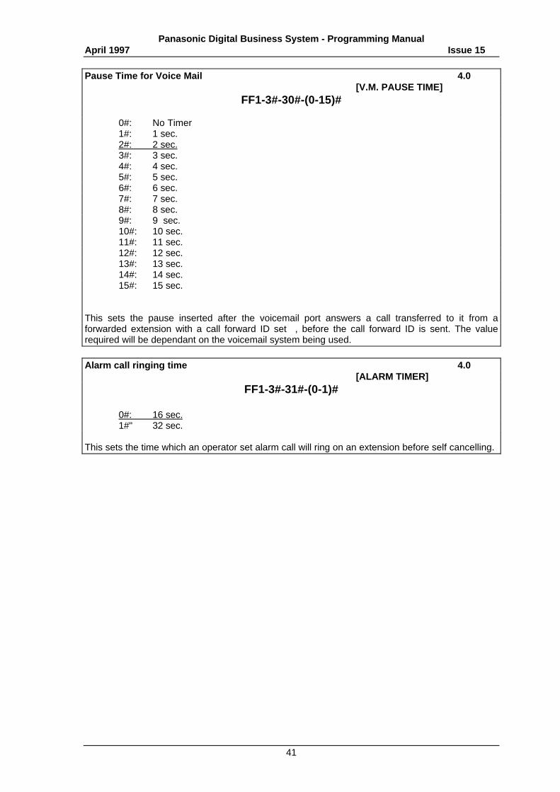
Pause Time for Voice Mail 4.0[V.M. PAUSE TIME]
FF1-3#-30#-(0-15)#
0#: No Timer1#: 1 sec.2#: 2 sec.3#: 3 sec.4#: 4 sec.5#: 5 sec.6#: 6 sec.7#: 7 sec.8#: 8 sec.9#: 9 sec.10#: 10 sec.11#: 11 sec.12#: 12 sec.13#: 13 sec.14#: 14 sec.15#: 15 sec.
This sets the pause inserted after the voicemail port answers a call transferred to it from aforwarded extension with a call forward ID set , before the call forward ID is sent. The valuerequired will be dependant on the voicemail system being used.
Alarm call ringing time 4.0[ALARM TIMER]
FF1-3#-31#-(0-1)#
0#: 16 sec.1#" 32 sec.
This sets the time which an operator set alarm call will ring on an extension before self cancelling.
Panasonic Digital Business System - Programming ManualApril 1997 Issue 15
42
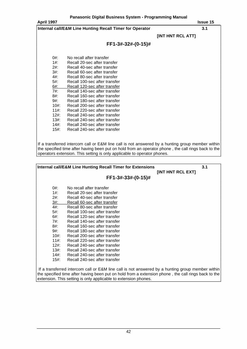
Internal call/E&M Line Hunting Recall Timer for Operator 3.1
[INT HNT RCL ATT]
FF1-3#-32#-(0-15)#
0#: No recall after transfer1#: Recall 20-sec after transfer2#: Recall 40-sec after transfer3#: Recall 60-sec after transfer4#: Recall 80-sec after transfer5#: Recall 100-sec after transfer6#: Recall 120-sec after transfer7#: Recall 140-sec after transfer8#: Recall 160-sec after transfer9#: Recall 180-sec after transfer10#: Recall 200-sec after transfer11#: Recall 220-sec after transfer12#: Recall 240-sec after transfer13#: Recall 240-sec after transfer14#: Recall 240-sec after transfer15#: Recall 240-sec after transfer
If a transferred intercom call or E&M line call is not answered by a hunting group member withinthe specified time after having been put on hold from an operator phone , the call rings back to theoperators extension. This setting is only applicable to operator phones.
Internal call/E&M Line Hunting Recall Timer for Extensions 3.1[INT HNT RCL EXT]
FF1-3#-33#-(0-15)#
0#: No recall after transfer1#: Recall 20-sec after transfer2#: Recall 40-sec after transfer3#: Recall 60-sec after transfer4#: Recall 80-sec after transfer5#: Recall 100-sec after transfer6#: Recall 120-sec after transfer7#: Recall 140-sec after transfer8#: Recall 160-sec after transfer9#: Recall 180-sec after transfer10#: Recall 200-sec after transfer11#: Recall 220-sec after transfer12#: Recall 240-sec after transfer13#: Recall 240-sec after transfer14#: Recall 240-sec after transfer15#: Recall 240-sec after transfer
If a transferred intercom call or E&M line call is not answered by a hunting group member withinthe specified time after having been put on hold from a extension phone , the call rings back to theextension. This setting is only applicable to extension phones.
Panasonic Digital Business System - Programming ManualApril 1997 Issue 15
43
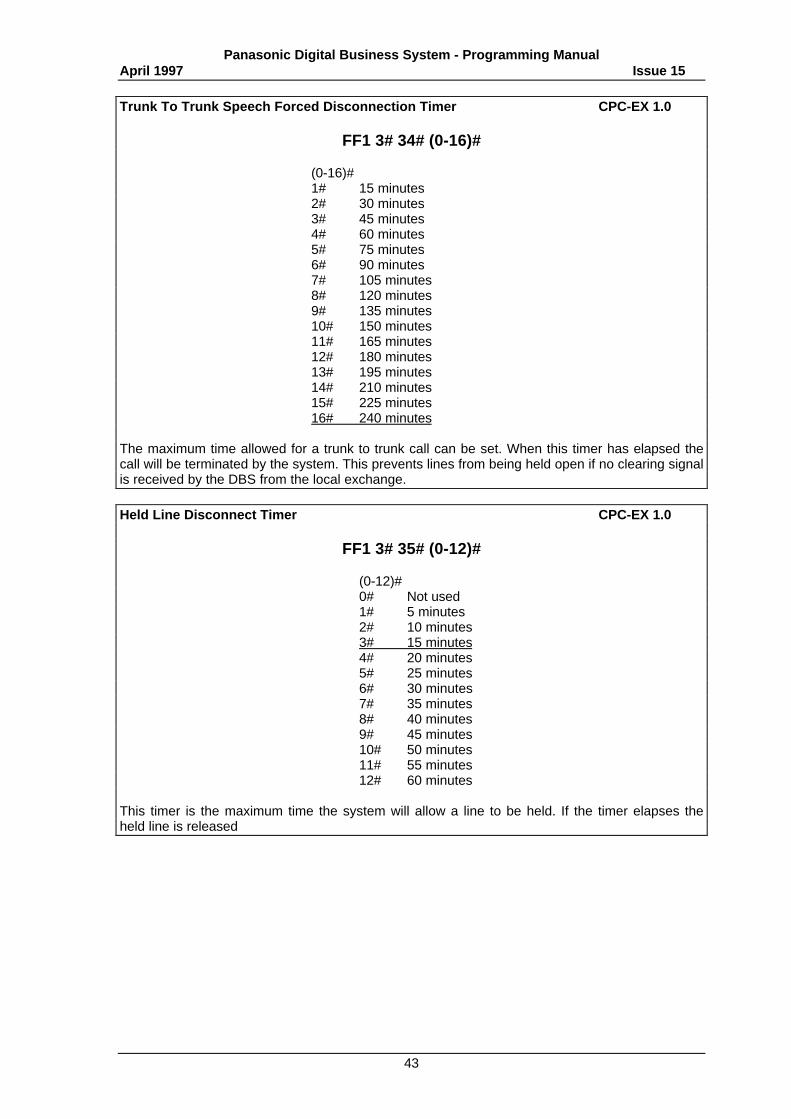
Trunk To Trunk Speech Forced Disconnection Timer CPC-EX 1.0
FF1 3# 34# (0-16)#
(0-16)#1# 15 minutes2# 30 minutes3# 45 minutes4# 60 minutes5# 75 minutes6# 90 minutes7# 105 minutes8# 120 minutes9# 135 minutes10# 150 minutes11# 165 minutes12# 180 minutes13# 195 minutes14# 210 minutes15# 225 minutes16# 240 minutes
The maximum time allowed for a trunk to trunk call can be set. When this timer has elapsed thecall will be terminated by the system. This prevents lines from being held open if no clearing signalis received by the DBS from the local exchange.
Held Line Disconnect Timer CPC-EX 1.0
FF1 3# 35# (0-12)#
(0-12)#0# Not used1# 5 minutes2# 10 minutes3# 15 minutes4# 20 minutes5# 25 minutes6# 30 minutes7# 35 minutes8# 40 minutes9# 45 minutes10# 50 minutes11# 55 minutes12# 60 minutes
This timer is the maximum time the system will allow a line to be held. If the timer elapses theheld line is released
Panasonic Digital Business System - Programming ManualApril 1997 Issue 15
44
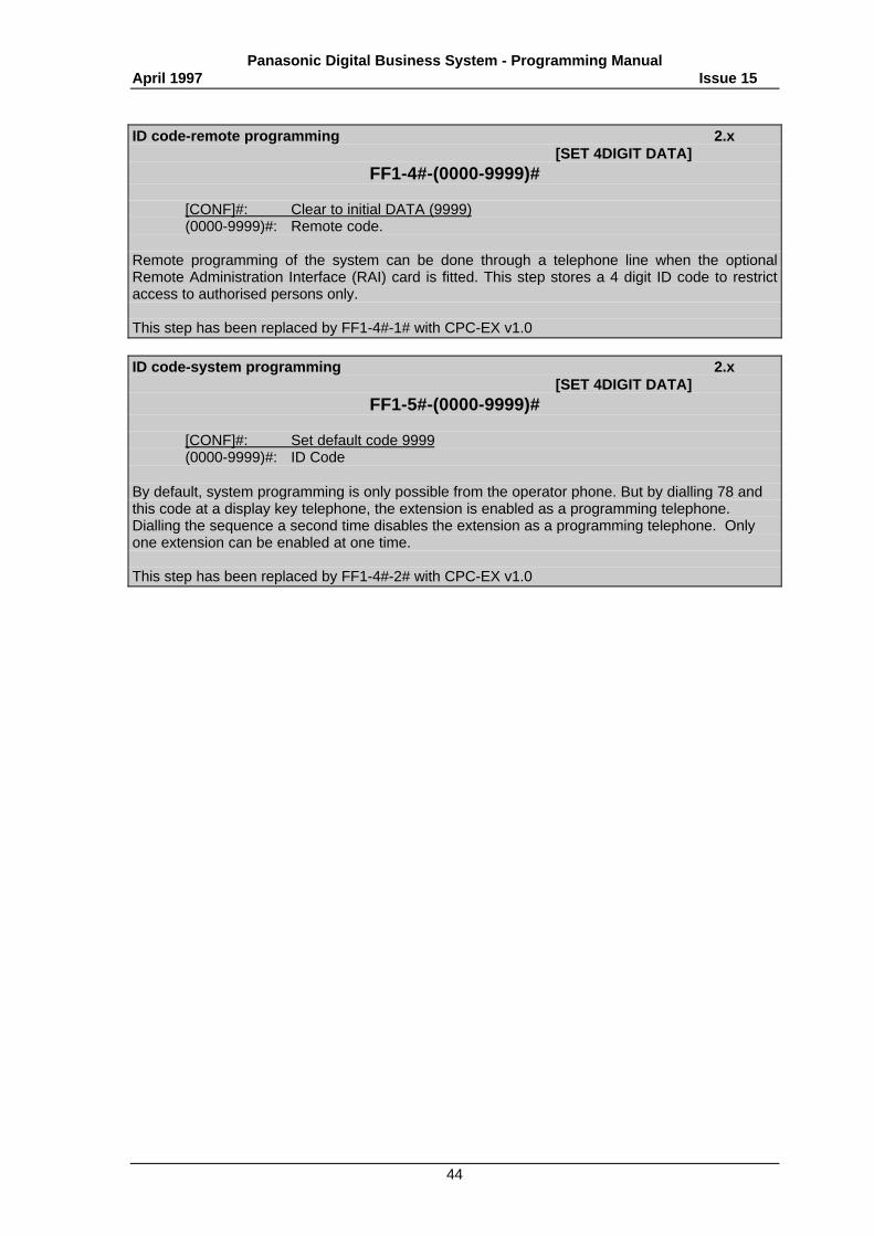
ID code-remote programming 2.x[SET 4DIGIT DATA]
FF1-4#-(0000-9999)#
[CONF]#: Clear to initial DATA (9999)(0000-9999)#: Remote code.
Remote programming of the system can be done through a telephone line when the optionalRemote Administration Interface (RAI) card is fitted. This step stores a 4 digit ID code to restrictaccess to authorised persons only.
This step has been replaced by FF1-4#-1# with CPC-EX v1.0
ID code-system programming 2.x[SET 4DIGIT DATA]
FF1-5#-(0000-9999)#
[CONF]#: Set default code 9999(0000-9999)#: ID Code
By default, system programming is only possible from the operator phone. But by dialling 78 andthis code at a display key telephone, the extension is enabled as a programming telephone.Dialling the sequence a second time disables the extension as a programming telephone. Onlyone extension can be enabled at one time.
This step has been replaced by FF1-4#-2# with CPC-EX v1.0
Panasonic Digital Business System - Programming ManualApril 1997 Issue 15
45
ID code-remote programming CPC-EX 1.0[SET 4DIGIT DATA]
FF1-4#-1#-(0000-9999)#
[CONF]#: Clear to initial DATA (9999)(0000-9999)#: Remote code.
Remote programming of the system can be done through a telephone line when the optionalRemote Administration Interface (RAI) card is fitted. This step stores a 4 digit ID code to restrictaccess to authorised persons only.
ID code-system programming CPC-EX 1.0[SET 4DIGIT DATA]
FF1-4#-2#-(0000-9999)#
[CONF]#: Set default code 9999(0000-9999)#: ID Code
By default, system programming is only possible from the operator phone. But by dialling 78 andthis code at a display key telephone, the extension is enabled as a programming telephone.Dialling the sequence a second time disables the extension as a programming telephone. Onlyone extension can be enabled at one time.
DISA Transfer ID CPC-EX 1.0
FF1 4# 4# (1,3,5,7,9)# (0000-9999)#
(1,3,5,7,9)# (0000-9999)#1# DISA TRF ID 1 4 digit ID code3# DISA TRF ID 25# DISA TRF ID 37# DISA TRF ID 49# DISA TRF ID 5
Store upto 5 DISA breakout IDs for use by external callers on DISA lines. This ID is required whenusing DISA to break out of the DBS. If no IDs are stored the DISA breakout facility is disabled.
DISA Transfer ID Tenant Group CPC-EX 1.0
FF1 4# 4# (2,4,6,8,10)# (1-8)#
(2,4,6,8,10)# (1-8)#1# DISA TRF ID 1 Tenant Group3# DISA TRF ID 25# DISA TRF ID 37# DISA TRF ID 49# DISA TRF ID 5
Assign a tenant group to use for each of the DISA TRF IDs in use. This is used to select a line by9 access when breaking out.
Panasonic Digital Business System - Programming ManualApril 1997 Issue 15
46
ID code-DISA access CPC-EX 1.0FF1-4#-3#-(0000-9999)#
[CONF]#: Clear data(0000-9999)# ID Code
When this step is set the ID code stored must be entered by the caller before the system willaccept extension routing digits from an incoming DISA call.
Note: To enable remote maintenance, it is necessary to input the remote program access codeseparately.
Related step FF2 1# (00-48)# 20# DISA line setting
System Size Setting ISDN 1.0 / CPC-EX 1.0
FF1 6# 1# 1# (0-5)# (P)
0# DBS 381# DBS 682# DBS 903# DBS 1284# DBS 1585# DBS 180
This sets the size of the system being installed to allow correct operation of the system software. Apower off / on reset is required when setting this step. This step must be set even if there is noDASS connection to ensure the connected line cards are correctly addressed by the software.
Setting The Number Of Analogue Lines ISDN 1.0 / CPC-EX 1.0
FF1 6# 1# 2# (0-8)# (P)
0# 0 Lines1# 6 Lines2# 12 Lines3# 18 Lines4# 24 Lines5# 30 Lines6# 36 Lines7# 42 Lines8# 48 Lines
This sets the number of analogue line cards and hence the maximum number of analogue lineswhich can be connected to the system. A power off / on reset is required when setting this step.This step must be correctly set even if there is no DASS connection to ensure all installed linecards are activated on the system. When counting the number of analogue cards work from slot 1upwards on the master CCU include the universal slot before moving onto the slave. (E.g.: DBS90slot 5 is the first line slot of the slave) When configuring the CCU there must be no gaps in thesequence of line card slots used or system capacity will be reduced unnecessarily as skipped slotswill still deduct line options from ISDN channel configuration options.
The number of analogue cards in the system includes all E&M, AC15A and TRK cards, all ofwhich count as analogue line cards.
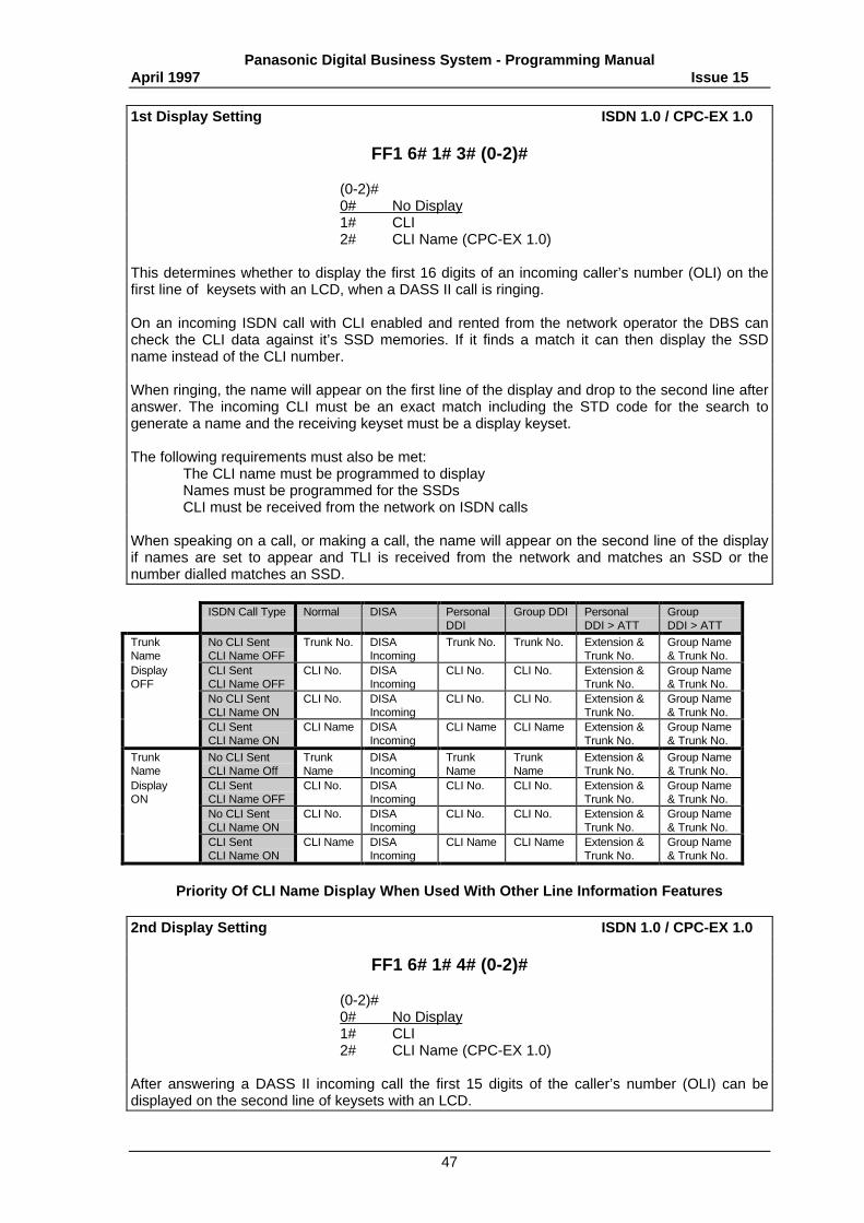
Panasonic Digital Business System - Programming ManualApril 1997 Issue 15
47
1st Display Setting ISDN 1.0 / CPC-EX 1.0
FF1 6# 1# 3# (0-2)#
(0-2)#0# No Display1# CLI2# CLI Name (CPC-EX 1.0)
This determines whether to display the first 16 digits of an incoming caller’s number (OLI) on thefirst line of keysets with an LCD, when a DASS II call is ringing.
On an incoming ISDN call with CLI enabled and rented from the network operator the DBS cancheck the CLI data against it’s SSD memories. If it finds a match it can then display the SSDname instead of the CLI number.
When ringing, the name will appear on the first line of the display and drop to the second line afteranswer. The incoming CLI must be an exact match including the STD code for the search togenerate a name and the receiving keyset must be a display keyset.
The following requirements must also be met:The CLI name must be programmed to displayNames must be programmed for the SSDsCLI must be received from the network on ISDN calls
When speaking on a call, or making a call, the name will appear on the second line of the displayif names are set to appear and TLI is received from the network and matches an SSD or thenumber dialled matches an SSD.
ISDN Call Type Normal DISA PersonalDDI
Group DDI PersonalDDI > ATT
GroupDDI > ATT
TrunkName
No CLI SentCLI Name OFF
Trunk No. DISAIncoming
Trunk No. Trunk No. Extension &Trunk No.
Group Name& Trunk No.
DisplayOFF
CLI SentCLI Name OFF
CLI No. DISAIncoming
CLI No. CLI No. Extension &Trunk No.
Group Name& Trunk No.
No CLI SentCLI Name ON
CLI No. DISAIncoming
CLI No. CLI No. Extension &Trunk No.
Group Name& Trunk No.
CLI SentCLI Name ON
CLI Name DISAIncoming
CLI Name CLI Name Extension &Trunk No.
Group Name& Trunk No.
TrunkName
No CLI SentCLI Name Off
TrunkName
DISAIncoming
TrunkName
TrunkName
Extension &Trunk No.
Group Name& Trunk No.
DisplayON
CLI SentCLI Name OFF
CLI No. DISAIncoming
CLI No. CLI No. Extension &Trunk No.
Group Name& Trunk No.
No CLI SentCLI Name ON
CLI No. DISAIncoming
CLI No. CLI No. Extension &Trunk No.
Group Name& Trunk No.
CLI SentCLI Name ON
CLI Name DISAIncoming
CLI Name CLI Name Extension &Trunk No.
Group Name& Trunk No.
Priority Of CLI Name Display When Used With Other Line Information Features
2nd Display Setting ISDN 1.0 / CPC-EX 1.0
FF1 6# 1# 4# (0-2)#
(0-2)#0# No Display1# CLI2# CLI Name (CPC-EX 1.0)
After answering a DASS II incoming call the first 15 digits of the caller’s number (OLI) can bedisplayed on the second line of keysets with an LCD.
Panasonic Digital Business System - Programming ManualApril 1997 Issue 15
48
Action When Other Party Is Busy ISDN 1.0
FF1 6# 1# 5# (0-1)#
0# Wait For Network Disconnect Signal1# Disconnect Without Waiting For Disconnect Signal
When an outgoing call on the DASS II channels receives busy the DBS can wait for the network tosend disconnect or disconnect without waiting for the network signal.
Display When Other Party Is Busy ISDN 1.0
FF1 6# 1# 6# (0-1)#
0# Display In Numbers1# Display In Characters
When the called party is busy the network will return status information to the DBS to show thereason. The DBS can display the numeric code or brief text explaining the cause to the LCD ofkeysets.
MC0 (Dial 9) Search ISDN 1.0
FF1 6# 1# 7# (0-1)#
0# Search DASS II Channels First1# Search Analogue Lines First
The DBS can search either the DASS II channels or analogue lines first when 9 is dialled to selecta line. If all lines of the preferred type are busy the search continues to the other lines.
DASS II Dialling Type CPC-EX 1.0 / 1.5
FF1 6# 1# 8# (0-1)#
(0-1)#0# Enblock dialling1# Overlap dialling
The DASS II signalling specification can be set for enblock ( all digits collected and sent in a singlemessage) or overlap (each digit is sent to the network as it is dialled).
The default setting of this step has been changed to Overlap dialling from this software level.
ISDN Protocol Selection CPC-EX v1.5
FF1 6# 1# 9# (0-1)#
0# Euro ISDN1# DASSII
Selection of the ISDN protocol to be connected to the system. If two ISDN cards are fitted theymust both use the same protocol.
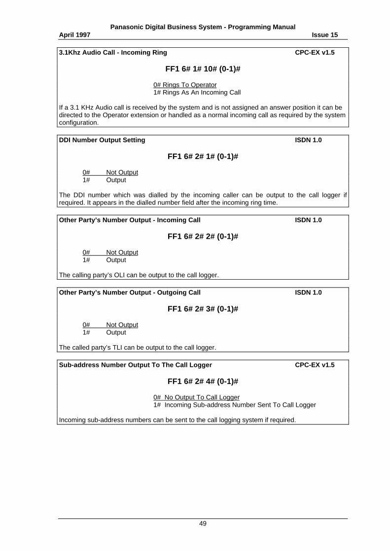
Panasonic Digital Business System - Programming ManualApril 1997 Issue 15
49
3.1Khz Audio Call - Incoming Ring CPC-EX v1.5
FF1 6# 1# 10# (0-1)#
0# Rings To Operator1# Rings As An Incoming Call
If a 3.1 KHz Audio call is received by the system and is not assigned an answer position it can bedirected to the Operator extension or handled as a normal incoming call as required by the systemconfiguration.
DDI Number Output Setting ISDN 1.0
FF1 6# 2# 1# (0-1)#
0# Not Output1# Output
The DDI number which was dialled by the incoming caller can be output to the call logger ifrequired. It appears in the dialled number field after the incoming ring time.
Other Party’s Number Output - Incoming Call ISDN 1.0
FF1 6# 2# 2# (0-1)#
0# Not Output1# Output
The calling party’s OLI can be output to the call logger.
Other Party’s Number Output - Outgoing Call ISDN 1.0
FF1 6# 2# 3# (0-1)#
0# Not Output1# Output
The called party’s TLI can be output to the call logger.
Sub-address Number Output To The Call Logger CPC-EX v1.5
FF1 6# 2# 4# (0-1)#
0# No Output To Call Logger1# Incoming Sub-address Number Sent To Call Logger
Incoming sub-address numbers can be sent to the call logging system if required.
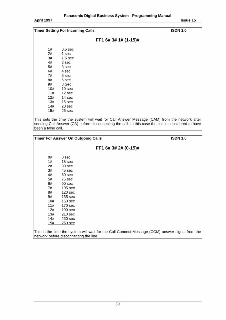
Panasonic Digital Business System - Programming ManualApril 1997 Issue 15
50
Timer Setting For Incoming Calls ISDN 1.0
FF1 6# 3# 1# (1-15)#
1# 0.5 sec2# 1 sec3# 1.5 sec4# 2 sec5# 3 sec6# 4 sec7# 5 sec8# 6 sec9# 8 Sec10# 10 sec11# 12 sec12# 14 sec13# 16 sec14# 20 sec15# 25 sec
This sets the time the system will wait for Call Answer Message (CAM) from the network aftersending Call Answer (CA) before disconnecting the call. In this case the call is considered to havebeen a false call.
Timer For Answer On Outgoing Calls ISDN 1.0
FF1 6# 3# 2# (0-15)#
0# 0 sec1# 15 sec2# 30 sec3# 45 sec4# 60 sec5# 75 sec6# 90 sec7# 105 sec8# 120 sec9# 135 sec10# 150 sec11# 170 sec12# 190 sec13# 210 sec14# 230 sec15# 250 sec
This is the time the system will wait for the Call Connect Message (CCM) answer signal from thenetwork before disconnecting the line.
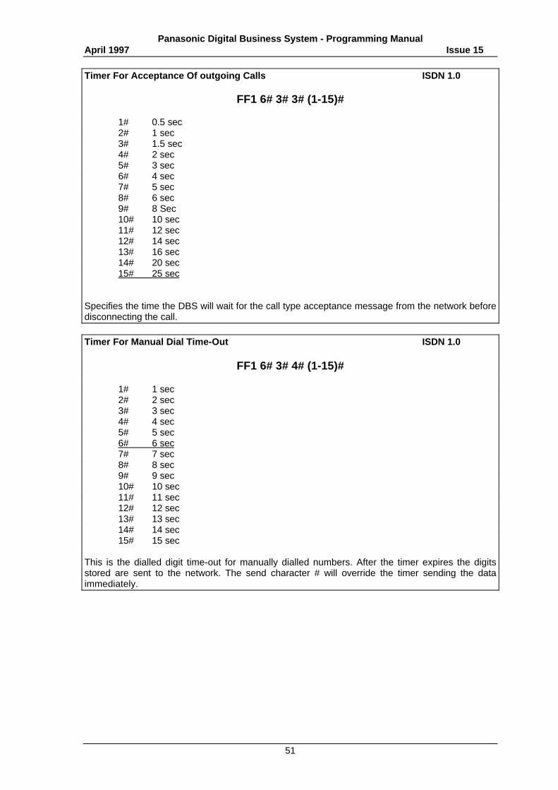
Panasonic Digital Business System - Programming ManualApril 1997 Issue 15
51
Timer For Acceptance Of outgoing Calls ISDN 1.0
FF1 6# 3# 3# (1-15)#
1# 0.5 sec2# 1 sec3# 1.5 sec4# 2 sec5# 3 sec6# 4 sec7# 5 sec8# 6 sec9# 8 Sec10# 10 sec11# 12 sec12# 14 sec13# 16 sec14# 20 sec15# 25 sec
Specifies the time the DBS will wait for the call type acceptance message from the network beforedisconnecting the call.
Timer For Manual Dial Time-Out ISDN 1.0
FF1 6# 3# 4# (1-15)#
1# 1 sec2# 2 sec3# 3 sec4# 4 sec5# 5 sec6# 6 sec7# 7 sec8# 8 sec9# 9 sec10# 10 sec11# 11 sec12# 12 sec13# 13 sec14# 14 sec15# 15 sec
This is the dialled digit time-out for manually dialled numbers. After the timer expires the digitsstored are sent to the network. The send character # will override the timer sending the dataimmediately.
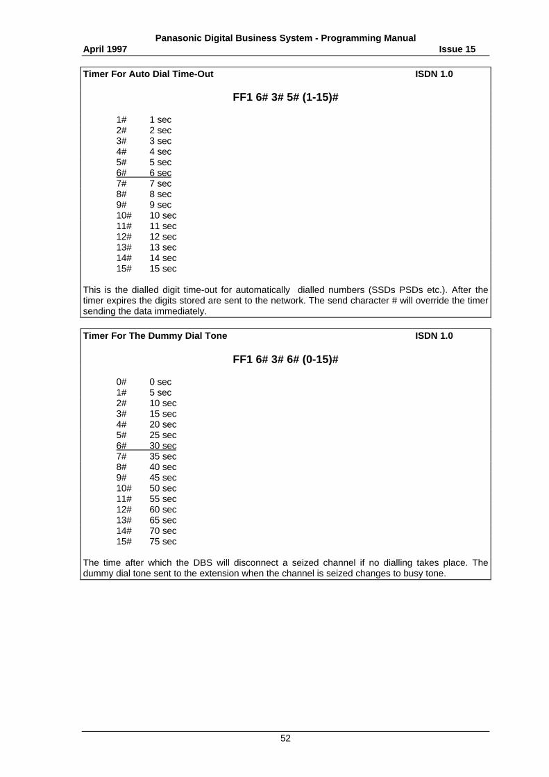
Panasonic Digital Business System - Programming ManualApril 1997 Issue 15
52
Timer For Auto Dial Time-Out ISDN 1.0
FF1 6# 3# 5# (1-15)#
1# 1 sec2# 2 sec3# 3 sec4# 4 sec5# 5 sec6# 6 sec7# 7 sec8# 8 sec9# 9 sec10# 10 sec11# 11 sec12# 12 sec13# 13 sec14# 14 sec15# 15 sec
This is the dialled digit time-out for automatically dialled numbers (SSDs PSDs etc.). After thetimer expires the digits stored are sent to the network. The send character # will override the timersending the data immediately.
Timer For The Dummy Dial Tone ISDN 1.0
FF1 6# 3# 6# (0-15)#
0# 0 sec1# 5 sec2# 10 sec3# 15 sec4# 20 sec5# 25 sec6# 30 sec7# 35 sec8# 40 sec9# 45 sec10# 50 sec11# 55 sec12# 60 sec13# 65 sec14# 70 sec15# 75 sec
The time after which the DBS will disconnect a seized channel if no dialling takes place. Thedummy dial tone sent to the extension when the channel is seized changes to busy tone.
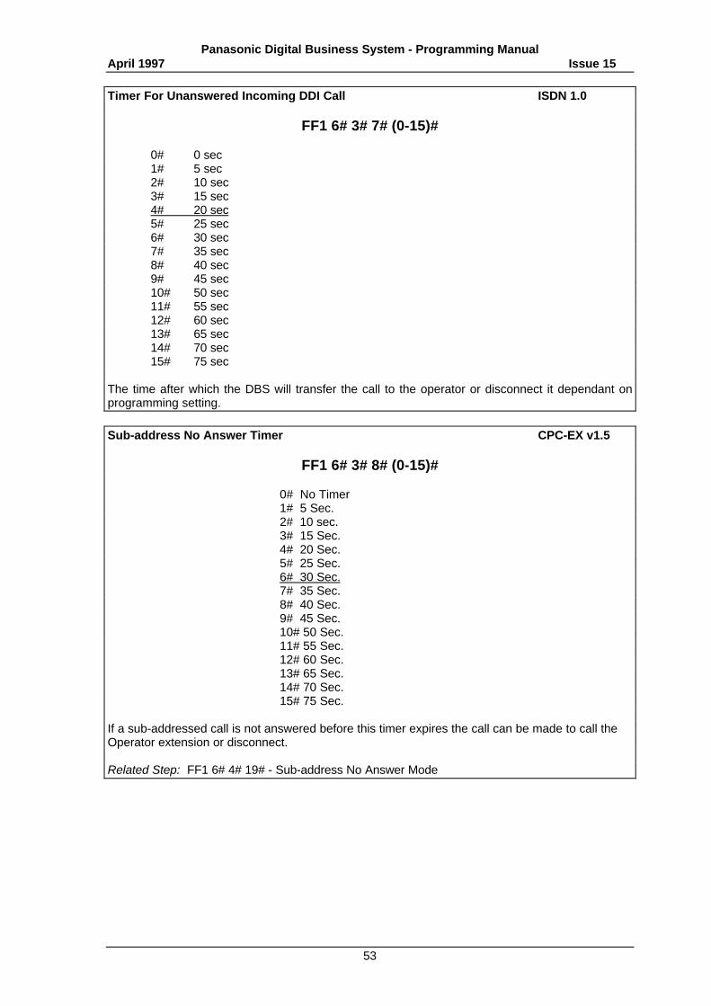
Panasonic Digital Business System - Programming ManualApril 1997 Issue 15
53
Timer For Unanswered Incoming DDI Call ISDN 1.0
FF1 6# 3# 7# (0-15)#
0# 0 sec1# 5 sec2# 10 sec3# 15 sec4# 20 sec5# 25 sec6# 30 sec7# 35 sec8# 40 sec9# 45 sec10# 50 sec11# 55 sec12# 60 sec13# 65 sec14# 70 sec15# 75 sec
The time after which the DBS will transfer the call to the operator or disconnect it dependant onprogramming setting.
Sub-address No Answer Timer CPC-EX v1.5
FF1 6# 3# 8# (0-15)#
0# No Timer1# 5 Sec.2# 10 sec.3# 15 Sec.4# 20 Sec.5# 25 Sec.6# 30 Sec.7# 35 Sec.8# 40 Sec.9# 45 Sec.10# 50 Sec.11# 55 Sec.12# 60 Sec.13# 65 Sec.14# 70 Sec.15# 75 Sec.
If a sub-addressed call is not answered before this timer expires the call can be made to call theOperator extension or disconnect.
Related Step: FF1 6# 4# 19# - Sub-address No Answer Mode
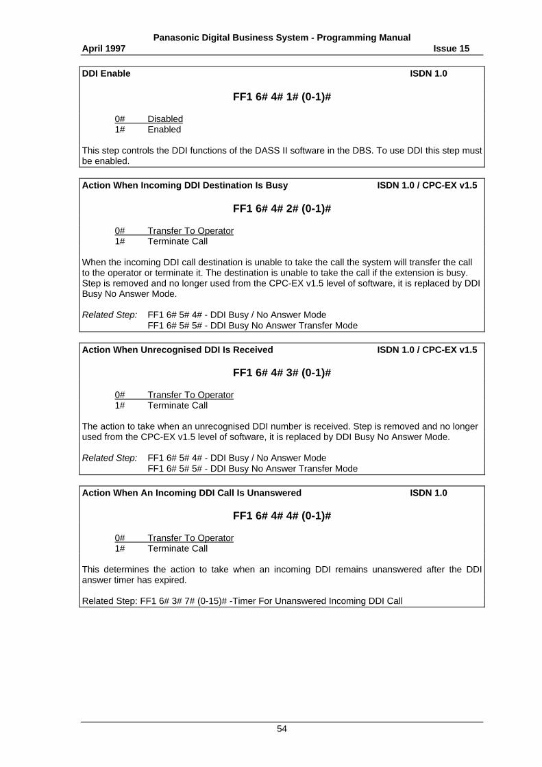
Panasonic Digital Business System - Programming ManualApril 1997 Issue 15
54
DDI Enable ISDN 1.0
FF1 6# 4# 1# (0-1)#
0# Disabled1# Enabled
This step controls the DDI functions of the DASS II software in the DBS. To use DDI this step mustbe enabled.
Action When Incoming DDI Destination Is Busy ISDN 1.0 / CPC-EX v1.5
FF1 6# 4# 2# (0-1)#
0# Transfer To Operator1# Terminate Call
When the incoming DDI call destination is unable to take the call the system will transfer the callto the operator or terminate it. The destination is unable to take the call if the extension is busy.Step is removed and no longer used from the CPC-EX v1.5 level of software, it is replaced by DDIBusy No Answer Mode.
Related Step: FF1 6# 5# 4# - DDI Busy / No Answer ModeFF1 6# 5# 5# - DDI Busy No Answer Transfer Mode
Action When Unrecognised DDI Is Received ISDN 1.0 / CPC-EX v1.5
FF1 6# 4# 3# (0-1)#
0# Transfer To Operator1# Terminate Call
The action to take when an unrecognised DDI number is received. Step is removed and no longerused from the CPC-EX v1.5 level of software, it is replaced by DDI Busy No Answer Mode.
Related Step: FF1 6# 5# 4# - DDI Busy / No Answer ModeFF1 6# 5# 5# - DDI Busy No Answer Transfer Mode
Action When An Incoming DDI Call Is Unanswered ISDN 1.0
FF1 6# 4# 4# (0-1)#
0# Transfer To Operator1# Terminate Call
This determines the action to take when an incoming DDI remains unanswered after the DDIanswer timer has expired.
Related Step: FF1 6# 3# 7# (0-15)# -Timer For Unanswered Incoming DDI Call
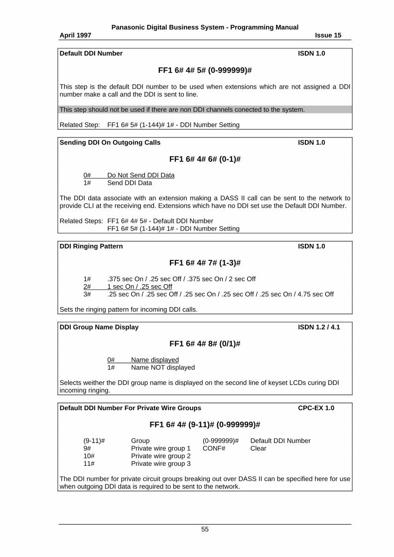
Panasonic Digital Business System - Programming ManualApril 1997 Issue 15
55
Default DDI Number ISDN 1.0
FF1 6# 4# 5# (0-999999)#
This step is the default DDI number to be used when extensions which are not assigned a DDInumber make a call and the DDI is sent to line.
This step should not be used if there are non DDI channels conected to the system.
Related Step: FF1 6# 5# (1-144)# 1# - DDI Number Setting
Sending DDI On Outgoing Calls ISDN 1.0
FF1 6# 4# 6# (0-1)#
0# Do Not Send DDI Data1# Send DDI Data
The DDI data associate with an extension making a DASS II call can be sent to the network toprovide CLI at the receiving end. Extensions which have no DDI set use the Default DDI Number.
Related Steps: FF1 6# 4# 5# - Default DDI NumberFF1 6# 5# (1-144)# 1# - DDI Number Setting
DDI Ringing Pattern ISDN 1.0
FF1 6# 4# 7# (1-3)#
1# .375 sec On / .25 sec Off / .375 sec On / 2 sec Off2# 1 sec On / .25 sec Off3# .25 sec On / .25 sec Off / .25 sec On / .25 sec Off / .25 sec On / 4.75 sec Off
Sets the ringing pattern for incoming DDI calls.
DDI Group Name Display ISDN 1.2 / 4.1
FF1 6# 4# 8# (0/1)#
0# Name displayed1# Name NOT displayed
Selects weither the DDI group name is displayed on the second line of keyset LCDs curing DDIincoming ringing.
Default DDI Number For Private Wire Groups CPC-EX 1.0
FF1 6# 4# (9-11)# (0-999999)#
(9-11)# Group (0-999999)# Default DDI Number9# Private wire group 1 CONF# Clear10# Private wire group 211# Private wire group 3
The DDI number for private circuit groups breaking out over DASS II can be specified here for usewhen outgoing DDI data is required to be sent to the network.
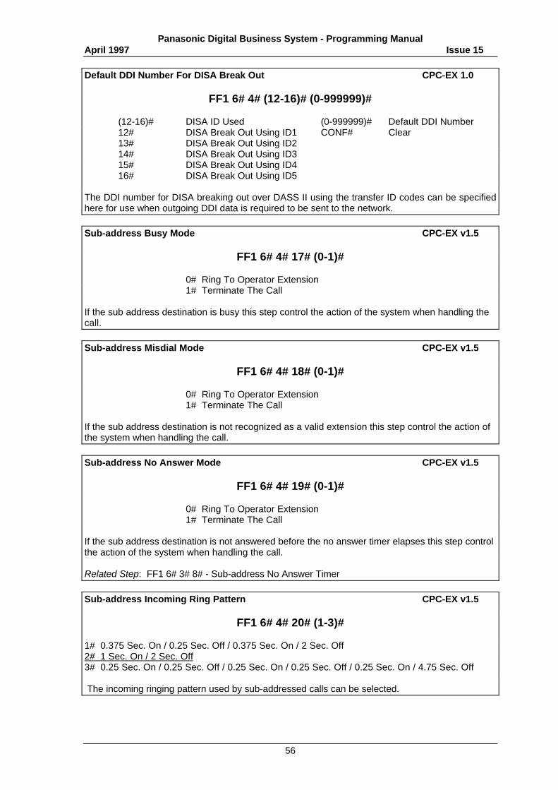
Panasonic Digital Business System - Programming ManualApril 1997 Issue 15
56
Default DDI Number For DISA Break Out CPC-EX 1.0
FF1 6# 4# (12-16)# (0-999999)#
(12-16)# DISA ID Used (0-999999)# Default DDI Number12# DISA Break Out Using ID1 CONF# Clear13# DISA Break Out Using ID214# DISA Break Out Using ID315# DISA Break Out Using ID416# DISA Break Out Using ID5
The DDI number for DISA breaking out over DASS II using the transfer ID codes can be specifiedhere for use when outgoing DDI data is required to be sent to the network.
Sub-address Busy Mode CPC-EX v1.5
FF1 6# 4# 17# (0-1)#
0# Ring To Operator Extension1# Terminate The Call
If the sub address destination is busy this step control the action of the system when handling thecall.
Sub-address Misdial Mode CPC-EX v1.5
FF1 6# 4# 18# (0-1)#
0# Ring To Operator Extension1# Terminate The Call
If the sub address destination is not recognized as a valid extension this step control the action ofthe system when handling the call.
Sub-address No Answer Mode CPC-EX v1.5
FF1 6# 4# 19# (0-1)#
0# Ring To Operator Extension1# Terminate The Call
If the sub address destination is not answered before the no answer timer elapses this step controlthe action of the system when handling the call.
Related Step: FF1 6# 3# 8# - Sub-address No Answer Timer
Sub-address Incoming Ring Pattern CPC-EX v1.5
FF1 6# 4# 20# (1-3)#
1# 0.375 Sec. On / 0.25 Sec. Off / 0.375 Sec. On / 2 Sec. Off2# 1 Sec. On / 2 Sec. Off3# 0.25 Sec. On / 0.25 Sec. Off / 0.25 Sec. On / 0.25 Sec. Off / 0.25 Sec. On / 4.75 Sec. Off
The incoming ringing pattern used by sub-addressed calls can be selected.
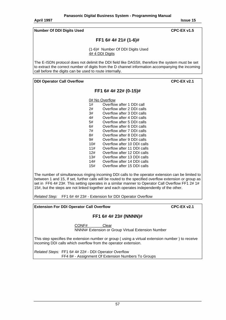
Panasonic Digital Business System - Programming ManualApril 1997 Issue 15
57
Number Of DDI Digits Used CPC-EX v1.5
FF1 6# 4# 21# (1-6)#
(1-6)# Number Of DDI Digits Used4# 4 DDI Digits
The E-ISDN protocol does not delimit the DDI field like DASSII, therefore the system must be setto extract the correct number of digits from the D channel information accompanying the incomingcall before the digits can be used to route internally.
DDI Operator Call Overflow CPC-EX v2.1
FF1 6# 4# 22# (0-15)#
0# No Overflow1# Overflow after 1 DDI call2# Overflow after 2 DDI calls3# Overflow after 3 DDI calls4# Overflow after 4 DDI calls5# Overflow after 5 DDI calls6# Overflow after 6 DDI calls7# Overflow after 7 DDI calls8# Overflow after 8 DDI calls9# Overflow after 9 DDI calls10# Overflow after 10 DDI calls11# Overflow after 11 DDI calls12# Overflow after 12 DDI calls13# Overflow after 13 DDI calls14# Overflow after 14 DDI calls15# Overflow after 15 DDI calls
The number of simultaneous ringing incoming DDI calls to the operator extension can be limited tobetween 1 and 15, If set, further calls will be routed to the specified overflow extension or group asset in FF6 4# 23#. This setting operates in a similar manner to Operator Call Overflow FF1 2# 1#15#, but the steps are not linked together and each operates independently of the other.
Related Step: FF1 6# 4# 23# - Extension for DDI Operator Overflow
Extension For DDI Operator Call Overflow CPC-EX v2.1
FF1 6# 4# 23# (NNNN)#
CONF# ClearNNNN# Extension or Group Virtual Extension Number
This step specifies the extension number or group ( using a virtual extension number ) to receiveincoming DDI calls which overflow from the operator extension.
Related Steps: FF1 6# 4# 22# - DDI Operator OverflowFF4 8# - Assignment Of Extension Numbers To Groups
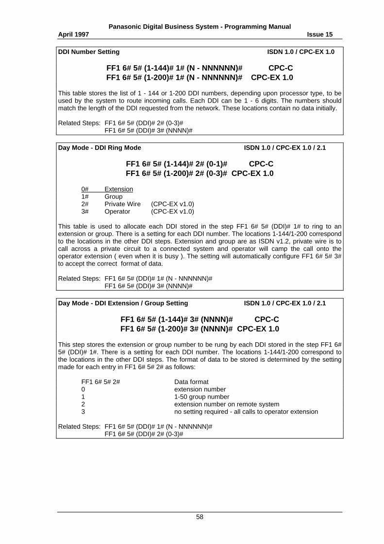
Panasonic Digital Business System - Programming ManualApril 1997 Issue 15
58
DDI Number Setting ISDN 1.0 / CPC-EX 1.0
FF1 6# 5# (1-144)# 1# (N - NNNNNN)# CPC-CFF1 6# 5# (1-200)# 1# (N - NNNNNN)# CPC-EX 1.0
This table stores the list of 1 - 144 or 1-200 DDI numbers, depending upon processor type, to beused by the system to route incoming calls. Each DDI can be 1 - 6 digits. The numbers shouldmatch the length of the DDI requested from the network. These locations contain no data initially.
Related Steps: FF1 6# 5# (DDI)# 2# (0-3)#FF1 6# 5# (DDI)# 3# (NNNN)#
Day Mode - DDI Ring Mode ISDN 1.0 / CPC-EX 1.0 / 2.1
FF1 6# 5# (1-144)# 2# (0-1)# CPC-CFF1 6# 5# (1-200)# 2# (0-3)# CPC-EX 1.0
0# Extension1# Group2# Private Wire (CPC-EX v1.0)3# Operator (CPC-EX v1.0)
This table is used to allocate each DDI stored in the step FF1 6# 5# (DDI)# 1# to ring to anextension or group. There is a setting for each DDI number. The locations 1-144/1-200 correspondto the locations in the other DDI steps. Extension and group are as ISDN v1.2, private wire is tocall across a private circuit to a connected system and operator will camp the call onto theoperator extension ( even when it is busy ). The setting will automatically configure FF1 6# 5# 3#to accept the correct format of data.
Related Steps: FF1 6# 5# (DDI)# 1# (N - NNNNNN)#FF1 6# 5# (DDI)# 3# (NNNN)#
Day Mode - DDI Extension / Group Setting ISDN 1.0 / CPC-EX 1.0 / 2.1
FF1 6# 5# (1-144)# 3# (NNNN)# CPC-CFF1 6# 5# (1-200)# 3# (NNNN)# CPC-EX 1.0
This step stores the extension or group number to be rung by each DDI stored in the step FF1 6#5# (DDI)# 1#. There is a setting for each DDI number. The locations 1-144/1-200 correspond tothe locations in the other DDI steps. The format of data to be stored is determined by the settingmade for each entry in FF1 6# 5# 2# as follows:
FF1 6# 5# 2# Data format0 extension number1 1-50 group number2 extension number on remote system3 no setting required - all calls to operator extension
Related Steps: FF1 6# 5# (DDI)# 1# (N - NNNNNN)#FF1 6# 5# (DDI)# 2# (0-3)#
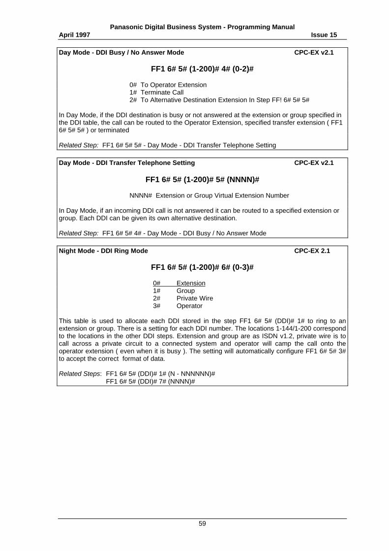
Panasonic Digital Business System - Programming ManualApril 1997 Issue 15
59
Day Mode - DDI Busy / No Answer Mode CPC-EX v2.1
FF1 6# 5# (1-200)# 4# (0-2)#
0# To Operator Extension1# Terminate Call2# To Alternative Destination Extension In Step FF! 6# 5# 5#
In Day Mode, if the DDI destination is busy or not answered at the extension or group specified inthe DDI table, the call can be routed to the Operator Extension, specified transfer extension ( FF16# 5# 5# ) or terminated
Related Step: FF1 6# 5# 5# - Day Mode - DDI Transfer Telephone Setting
Day Mode - DDI Transfer Telephone Setting CPC-EX v2.1
FF1 6# 5# (1-200)# 5# (NNNN)#
NNNN# Extension or Group Virtual Extension Number
In Day Mode, if an incoming DDI call is not answered it can be routed to a specified extension orgroup. Each DDI can be given its own alternative destination.
Related Step: FF1 6# 5# 4# - Day Mode - DDI Busy / No Answer Mode
Night Mode - DDI Ring Mode CPC-EX 2.1
FF1 6# 5# (1-200)# 6# (0-3)#
0# Extension1# Group2# Private Wire 3# Operator
This table is used to allocate each DDI stored in the step FF1 6# 5# (DDI)# 1# to ring to anextension or group. There is a setting for each DDI number. The locations 1-144/1-200 correspondto the locations in the other DDI steps. Extension and group are as ISDN v1.2, private wire is tocall across a private circuit to a connected system and operator will camp the call onto theoperator extension ( even when it is busy ). The setting will automatically configure FF1 6# 5# 3#to accept the correct format of data.
Related Steps: FF1 6# 5# (DDI)# 1# (N - NNNNNN)#FF1 6# 5# (DDI)# 7# (NNNN)#
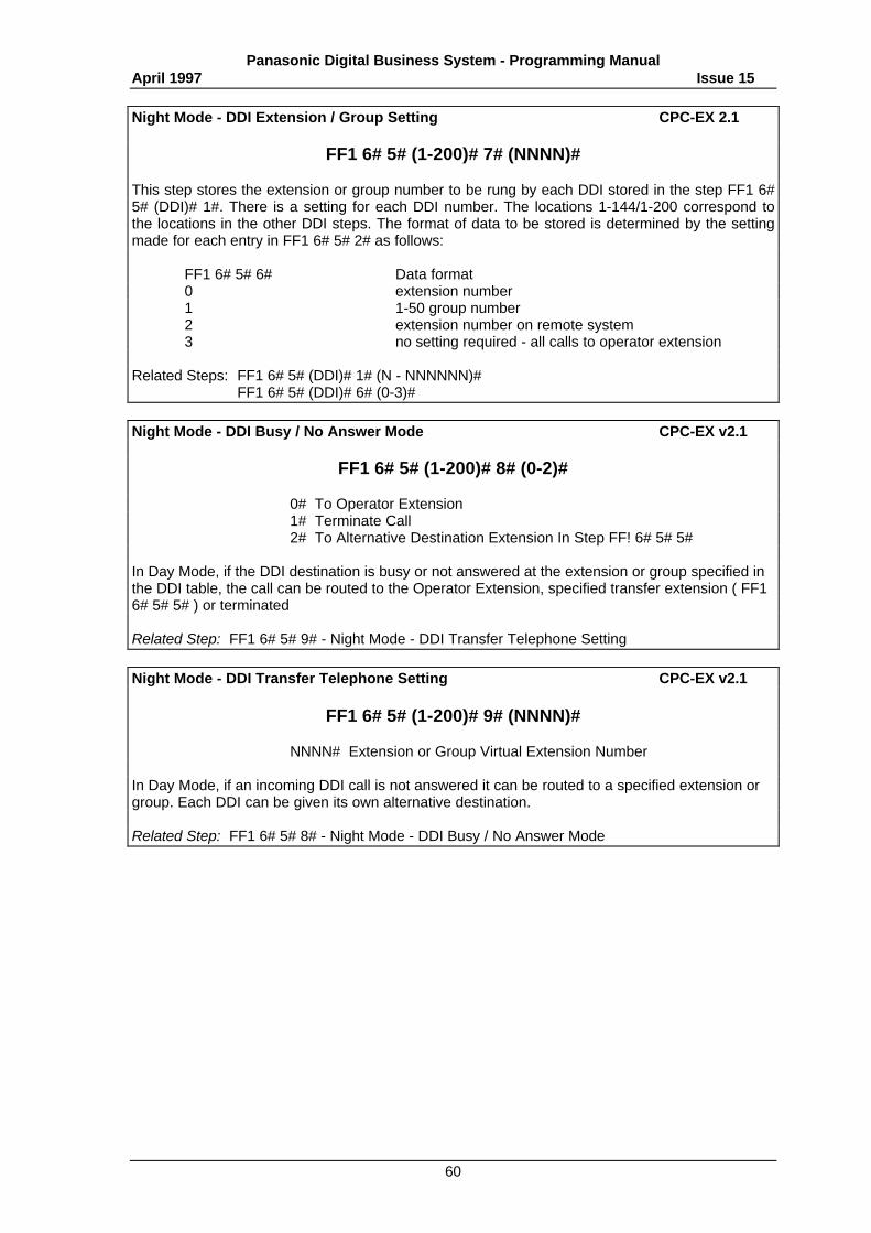
Panasonic Digital Business System - Programming ManualApril 1997 Issue 15
60
Night Mode - DDI Extension / Group Setting CPC-EX 2.1
FF1 6# 5# (1-200)# 7# (NNNN)#
This step stores the extension or group number to be rung by each DDI stored in the step FF1 6#5# (DDI)# 1#. There is a setting for each DDI number. The locations 1-144/1-200 correspond tothe locations in the other DDI steps. The format of data to be stored is determined by the settingmade for each entry in FF1 6# 5# 2# as follows:
FF1 6# 5# 6# Data format0 extension number1 1-50 group number2 extension number on remote system3 no setting required - all calls to operator extension
Related Steps: FF1 6# 5# (DDI)# 1# (N - NNNNNN)#FF1 6# 5# (DDI)# 6# (0-3)#
Night Mode - DDI Busy / No Answer Mode CPC-EX v2.1
FF1 6# 5# (1-200)# 8# (0-2)#
0# To Operator Extension1# Terminate Call2# To Alternative Destination Extension In Step FF! 6# 5# 5#
In Day Mode, if the DDI destination is busy or not answered at the extension or group specified inthe DDI table, the call can be routed to the Operator Extension, specified transfer extension ( FF16# 5# 5# ) or terminated
Related Step: FF1 6# 5# 9# - Night Mode - DDI Transfer Telephone Setting
Night Mode - DDI Transfer Telephone Setting CPC-EX v2.1
FF1 6# 5# (1-200)# 9# (NNNN)#
NNNN# Extension or Group Virtual Extension Number
In Day Mode, if an incoming DDI call is not answered it can be routed to a specified extension orgroup. Each DDI can be given its own alternative destination.
Related Step: FF1 6# 5# 8# - Night Mode - DDI Busy / No Answer Mode
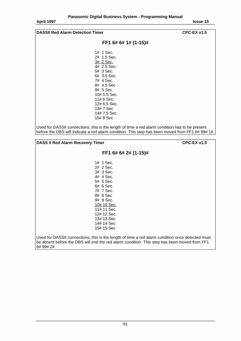
Panasonic Digital Business System - Programming ManualApril 1997 Issue 15
61
DASSII Red Alarm Detection Timer CPC-EX v1.5
FF1 6# 6# 1# (1-15)#
1# 1 Sec.2# 1.5 Sec.3# 2 Sec.4# 2.5 Sec.5# 3 Sec.6# 3.5 Sec.7# 4 Sec.8# 4.5 Sec9# 5 Sec.10# 5.5 Sec.11# 6 Sec.12# 6.5 Sec.13# 7 Sec14# 7.5 Sec15# 8 Sec
Used for DASSII connections, this is the length of time a red alarm condition has to be presentbefore the DBS will indicate a red alarm condition. This step has been moved from FF1 6# 99# 1#.
DASS II Red Alarm Recovery Timer CPC-EX v1.5
FF1 6# 6# 2# (1-15)#
1# 1 Sec.2# 2 Sec.3# 3 Sec.4# 4 Sec.5# 5 Sec.6# 6 Sec.7# 7 Sec.8# 8 Sec9# 9 Sec.10# 10 Sec.11# 11 Sec.12# 12 Sec.13# 13 Sec14# 14 Sec15# 15 Sec
Used for DASSII connections, this is the length of time a red alarm condition once detected mustbe absent before the DBS will end the red alarm condition. This step has been moved from FF16# 99# 2#.
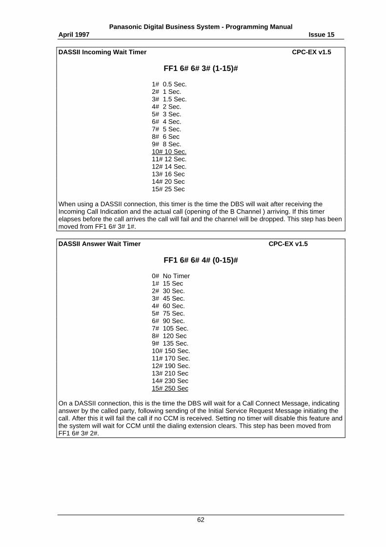
Panasonic Digital Business System - Programming ManualApril 1997 Issue 15
62
DASSII Incoming Wait Timer CPC-EX v1.5
FF1 6# 6# 3# (1-15)#
1# 0.5 Sec.2# 1 Sec.3# 1.5 Sec.4# 2 Sec.5# 3 Sec.6# 4 Sec.7# 5 Sec.8# 6 Sec9# 8 Sec.10# 10 Sec.11# 12 Sec.12# 14 Sec.13# 16 Sec14# 20 Sec15# 25 Sec
When using a DASSII connection, this timer is the time the DBS will wait after receiving theIncoming Call Indication and the actual call (opening of the B Channel ) arriving. If this timerelapses before the call arrives the call will fail and the channel will be dropped. This step has beenmoved from FF1 6# 3# 1#.
DASSII Answer Wait Timer CPC-EX v1.5
FF1 6# 6# 4# (0-15)#
0# No Timer1# 15 Sec2# 30 Sec.3# 45 Sec.4# 60 Sec.5# 75 Sec.6# 90 Sec.7# 105 Sec.8# 120 Sec9# 135 Sec.10# 150 Sec.11# 170 Sec.12# 190 Sec.13# 210 Sec14# 230 Sec15# 250 Sec
On a DASSII connection, this is the time the DBS will wait for a Call Connect Message, indicatinganswer by the called party, following sending of the Initial Service Request Message initiating thecall. After this it will fail the call if no CCM is received. Setting no timer will disable this feature andthe system will wait for CCM until the dialing extension clears. This step has been moved fromFF1 6# 3# 2#.
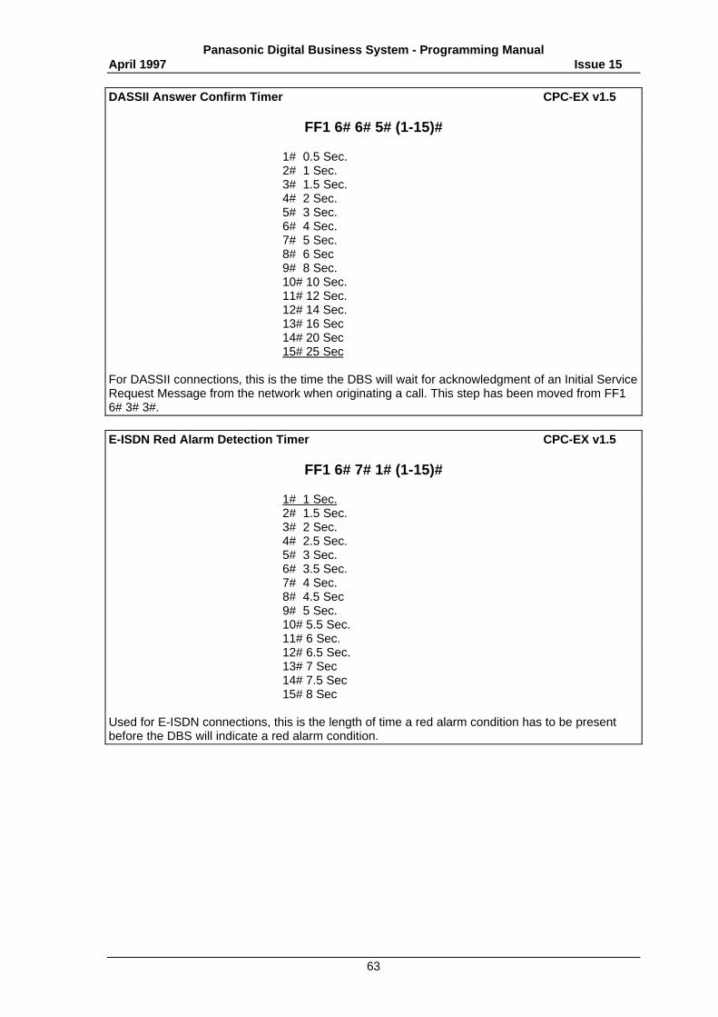
Panasonic Digital Business System - Programming ManualApril 1997 Issue 15
63
DASSII Answer Confirm Timer CPC-EX v1.5
FF1 6# 6# 5# (1-15)#
1# 0.5 Sec.2# 1 Sec.3# 1.5 Sec.4# 2 Sec.5# 3 Sec.6# 4 Sec.7# 5 Sec.8# 6 Sec9# 8 Sec.10# 10 Sec.11# 12 Sec.12# 14 Sec.13# 16 Sec14# 20 Sec15# 25 Sec
For DASSII connections, this is the time the DBS will wait for acknowledgment of an Initial ServiceRequest Message from the network when originating a call. This step has been moved from FF16# 3# 3#.
E-ISDN Red Alarm Detection Timer CPC-EX v1.5
FF1 6# 7# 1# (1-15)#
1# 1 Sec.2# 1.5 Sec.3# 2 Sec.4# 2.5 Sec.5# 3 Sec.6# 3.5 Sec.7# 4 Sec.8# 4.5 Sec9# 5 Sec.10# 5.5 Sec.11# 6 Sec.12# 6.5 Sec.13# 7 Sec14# 7.5 Sec15# 8 Sec
Used for E-ISDN connections, this is the length of time a red alarm condition has to be presentbefore the DBS will indicate a red alarm condition.
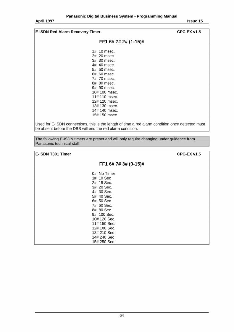
Panasonic Digital Business System - Programming ManualApril 1997 Issue 15
64
E-ISDN Red Alarm Recovery Timer CPC-EX v1.5
FF1 6# 7# 2# (1-15)#
1# 10 msec.2# 20 msec.3# 30 msec.4# 40 msec.5# 50 msec.6# 60 msec.7# 70 msec.8# 80 msec.9# 90 msec.10# 100 msec.11# 110 msec.12# 120 msec.13# 130 msec.14# 140 msec.15# 150 msec.
Used for E-ISDN connections, this is the length of time a red alarm condition once detected mustbe absent before the DBS will end the red alarm condition.
The following E-ISDN timers are preset and will only require changing under guidance fromPanasonic technical staff.
E-ISDN T301 Timer CPC-EX v1.5
FF1 6# 7# 3# (0-15)#
0# No Timer1# 10 Sec2# 15 Sec.3# 20 Sec.4# 30 Sec.5# 40 Sec.6# 50 Sec.7# 60 Sec.8# 80 Sec9# 100 Sec.10# 120 Sec.11# 150 Sec.12# 180 Sec.13# 210 Sec14# 240 Sec15# 250 Sec
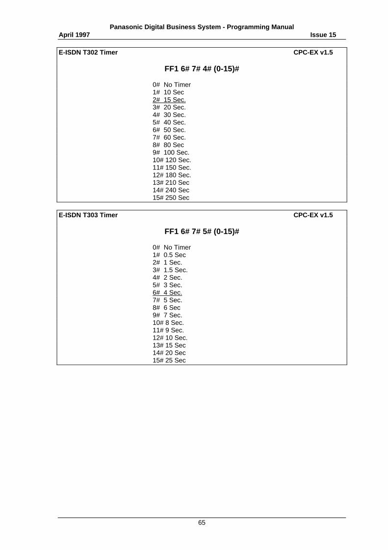
Panasonic Digital Business System - Programming ManualApril 1997 Issue 15
65
E-ISDN T302 Timer CPC-EX v1.5
FF1 6# 7# 4# (0-15)#
0# No Timer1# 10 Sec2# 15 Sec.3# 20 Sec.4# 30 Sec.5# 40 Sec.6# 50 Sec.7# 60 Sec.8# 80 Sec9# 100 Sec.10# 120 Sec.11# 150 Sec.12# 180 Sec.13# 210 Sec14# 240 Sec15# 250 Sec
E-ISDN T303 Timer CPC-EX v1.5
FF1 6# 7# 5# (0-15)#
0# No Timer1# 0.5 Sec2# 1 Sec.3# 1.5 Sec.4# 2 Sec.5# 3 Sec.6# 4 Sec.7# 5 Sec.8# 6 Sec9# 7 Sec.10# 8 Sec.11# 9 Sec.12# 10 Sec.13# 15 Sec14# 20 Sec15# 25 Sec

Panasonic Digital Business System - Programming ManualApril 1997 Issue 15
66
E-ISDN T304 Timer CPC-EX v1.5
FF1 6# 7# 6# (0-15)#
0# No Timer1# 10 Sec2# 15 Sec.3# 20 Sec.4# 30 Sec.5# 40 Sec.6# 50 Sec.7# 60 Sec.8# 80 Sec9# 100 Sec.10# 120 Sec.11# 150 Sec.12# 180 Sec.13# 210 Sec14# 240 Sec15# 250 Sec
E-ISDN T305 Timer CPC-EX v1.5
FF1 6# 7# 7# (0-15)#
0# No Timer1# 10 Sec2# 15 Sec.3# 20 Sec.4# 30 Sec.5# 40 Sec.6# 50 Sec.7# 60 Sec.8# 80 Sec9# 100 Sec.10# 120 Sec.11# 150 Sec.12# 180 Sec.13# 210 Sec14# 240 Sec15# 250 Sec
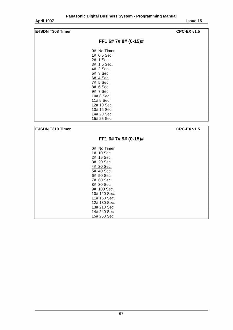
Panasonic Digital Business System - Programming ManualApril 1997 Issue 15
67
E-ISDN T308 Timer CPC-EX v1.5
FF1 6# 7# 8# (0-15)#
0# No Timer1# 0.5 Sec2# 1 Sec.3# 1.5 Sec.4# 2 Sec.5# 3 Sec.6# 4 Sec.7# 5 Sec.8# 6 Sec9# 7 Sec.10# 8 Sec.11# 9 Sec.12# 10 Sec.13# 15 Sec14# 20 Sec15# 25 Sec
E-ISDN T310 Timer CPC-EX v1.5
FF1 6# 7# 9# (0-15)#
0# No Timer1# 10 Sec2# 15 Sec.3# 20 Sec.4# 30 Sec.5# 40 Sec.6# 50 Sec.7# 60 Sec.8# 80 Sec9# 100 Sec.10# 120 Sec.11# 150 Sec.12# 180 Sec.13# 210 Sec14# 240 Sec15# 250 Sec

Panasonic Digital Business System - Programming ManualApril 1997 Issue 15
68
E-ISDN T313 Timer CPC-EX v1.5
FF1 6# 7# 10# (0-15)#
0# No Timer1# 0.5 Sec2# 1 Sec.3# 1.5 Sec.4# 2 Sec.5# 3 Sec.6# 4 Sec.7# 5 Sec.8# 6 Sec9# 7 Sec.10# 8 Sec.11# 9 Sec.12# 10 Sec.13# 15 Sec14# 20 Sec15# 25 Sec
E-ISDN T316 Timer CPC-EX v1.5
FF1 6# 7# 11# (0-15)#
0# No Timer1# 10 Sec2# 15 Sec.3# 20 Sec.4# 30 Sec.5# 40 Sec.6# 50 Sec.7# 60 Sec.8# 80 Sec9# 100 Sec.10# 120 Sec.11# 150 Sec.12# 180 Sec.13# 210 Sec14# 240 Sec15# 250 Sec
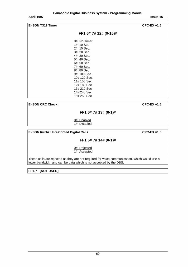
Panasonic Digital Business System - Programming ManualApril 1997 Issue 15
69
E-ISDN T317 Timer CPC-EX v1.5
FF1 6# 7# 12# (0-15)#
0# No Timer1# 10 Sec2# 15 Sec.3# 20 Sec.4# 30 Sec.5# 40 Sec.6# 50 Sec.7# 60 Sec.8# 80 Sec9# 100 Sec.10# 120 Sec.11# 150 Sec.12# 180 Sec.13# 210 Sec14# 240 Sec15# 250 Sec
E-ISDN CRC Check CPC-EX v1.5
FF1 6# 7# 13# (0-1)#
0# Enabled1# Disabled
E-ISDN 64Khz Unrestricted Digital Calls CPC-EX v1.5
FF1 6# 7# 14# (0-1)#
0# Rejected1# Accepted
These calls are rejected as they are not required for voice communication, which would use alower bandwidth and can be data which is not accepted by the DBS.
FF1-7 [NOT USED]
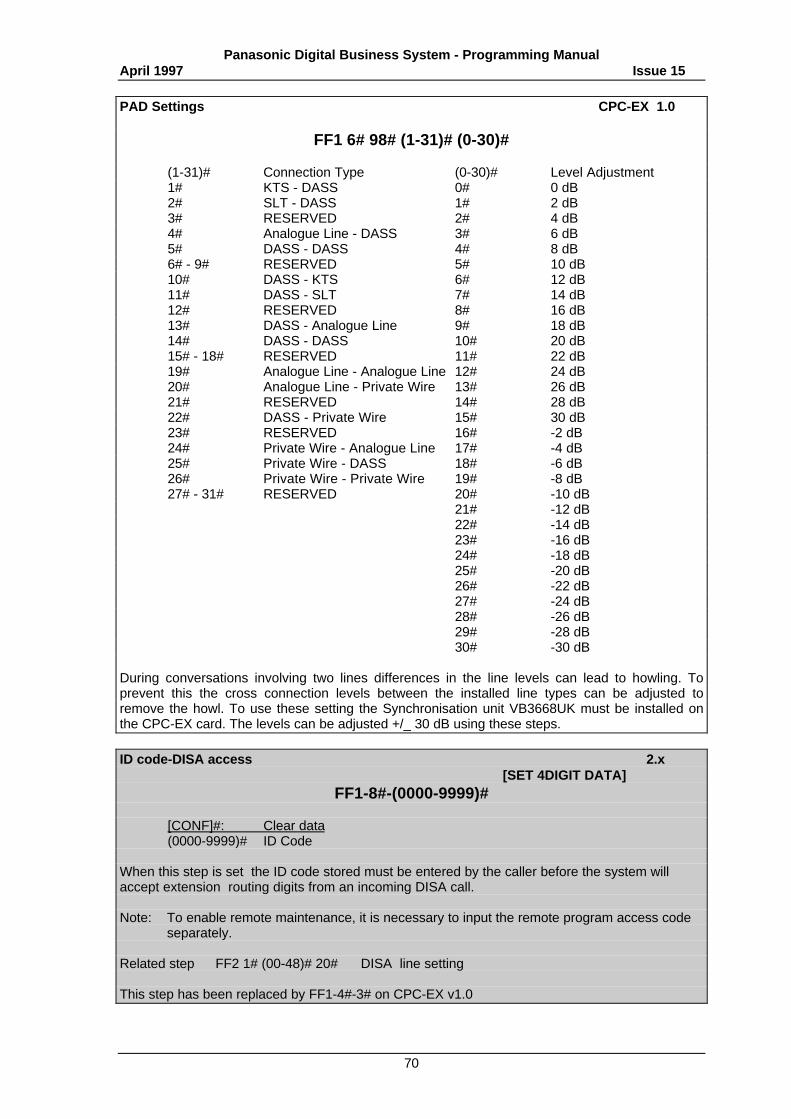
Panasonic Digital Business System - Programming ManualApril 1997 Issue 15
70
PAD Settings CPC-EX 1.0
FF1 6# 98# (1-31)# (0-30)#
(1-31)# Connection Type (0-30)# Level Adjustment1# KTS - DASS 0# 0 dB2# SLT - DASS 1# 2 dB3# RESERVED 2# 4 dB4# Analogue Line - DASS 3# 6 dB5# DASS - DASS 4# 8 dB6# - 9# RESERVED 5# 10 dB10# DASS - KTS 6# 12 dB11# DASS - SLT 7# 14 dB12# RESERVED 8# 16 dB13# DASS - Analogue Line 9# 18 dB14# DASS - DASS 10# 20 dB15# - 18# RESERVED 11# 22 dB19# Analogue Line - Analogue Line 12# 24 dB20# Analogue Line - Private Wire 13# 26 dB21# RESERVED 14# 28 dB22# DASS - Private Wire 15# 30 dB23# RESERVED 16# -2 dB24# Private Wire - Analogue Line 17# -4 dB25# Private Wire - DASS 18# -6 dB26# Private Wire - Private Wire 19# -8 dB27# - 31# RESERVED 20# -10 dB
21# -12 dB22# -14 dB23# -16 dB24# -18 dB25# -20 dB26# -22 dB27# -24 dB28# -26 dB29# -28 dB30# -30 dB
During conversations involving two lines differences in the line levels can lead to howling. Toprevent this the cross connection levels between the installed line types can be adjusted toremove the howl. To use these setting the Synchronisation unit VB3668UK must be installed onthe CPC-EX card. The levels can be adjusted +/_ 30 dB using these steps.
ID code-DISA access 2.x[SET 4DIGIT DATA]
FF1-8#-(0000-9999)#
[CONF]#: Clear data(0000-9999)# ID Code
When this step is set the ID code stored must be entered by the caller before the system willaccept extension routing digits from an incoming DISA call.
Note: To enable remote maintenance, it is necessary to input the remote program access codeseparately.
Related step FF2 1# (00-48)# 20# DISA line setting
This step has been replaced by FF1-4#-3# on CPC-EX v1.0
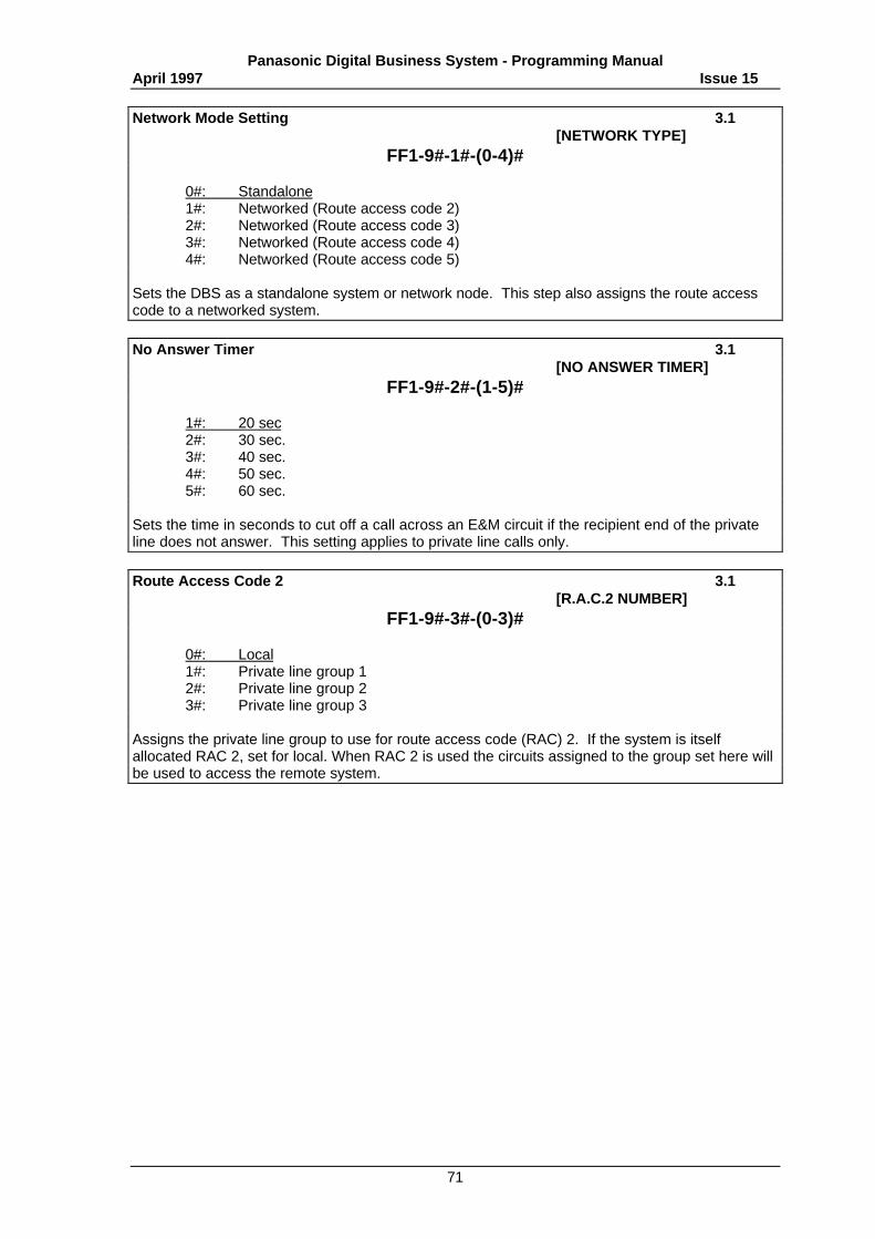
Panasonic Digital Business System - Programming ManualApril 1997 Issue 15
71
Network Mode Setting 3.1[NETWORK TYPE]
FF1-9#-1#-(0-4)#
0#: Standalone1#: Networked (Route access code 2)2#: Networked (Route access code 3)3#: Networked (Route access code 4)4#: Networked (Route access code 5)
Sets the DBS as a standalone system or network node. This step also assigns the route accesscode to a networked system.
No Answer Timer 3.1[NO ANSWER TIMER]
FF1-9#-2#-(1-5)#
1#: 20 sec2#: 30 sec.3#: 40 sec.4#: 50 sec.5#: 60 sec.
Sets the time in seconds to cut off a call across an E&M circuit if the recipient end of the privateline does not answer. This setting applies to private line calls only.
Route Access Code 2 3.1[R.A.C.2 NUMBER]
FF1-9#-3#-(0-3)#
0#: Local1#: Private line group 12#: Private line group 23#: Private line group 3
Assigns the private line group to use for route access code (RAC) 2. If the system is itselfallocated RAC 2, set for local. When RAC 2 is used the circuits assigned to the group set here willbe used to access the remote system.
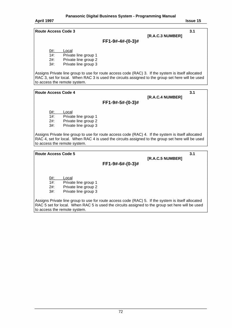
Panasonic Digital Business System - Programming ManualApril 1997 Issue 15
72
Route Access Code 3 3.1[R.A.C.3 NUMBER]
FF1-9#-4#-(0-3)#
0#: Local1#: Private line group 12#: Private line group 23#: Private line group 3
Assigns Private line group to use for route access code (RAC) 3. If the system is itself allocatedRAC 3, set for local. When RAC 3 is used the circuits assigned to the group set here will be usedto access the remote system.
Route Access Code 4 3.1[R.A.C.4 NUMBER]
FF1-9#-5#-(0-3)#
0#: Local1#: Private line group 12#: Private line group 23#: Private line group 3
Assigns Private line group to use for route access code (RAC) 4. If the system is itself allocatedRAC 4, set for local. When RAC 4 is used the circuits assigned to the group set here will be usedto access the remote system.
Route Access Code 5 3.1[R.A.C.5 NUMBER]
FF1-9#-6#-(0-3)#
0#: Local1#: Private line group 12#: Private line group 23#: Private line group 3
Assigns Private line group to use for route access code (RAC) 5. If the system is itself allocatedRAC 5 set for local. When RAC 5 is used the circuits assigned to the group set here will be usedto access the remote system.
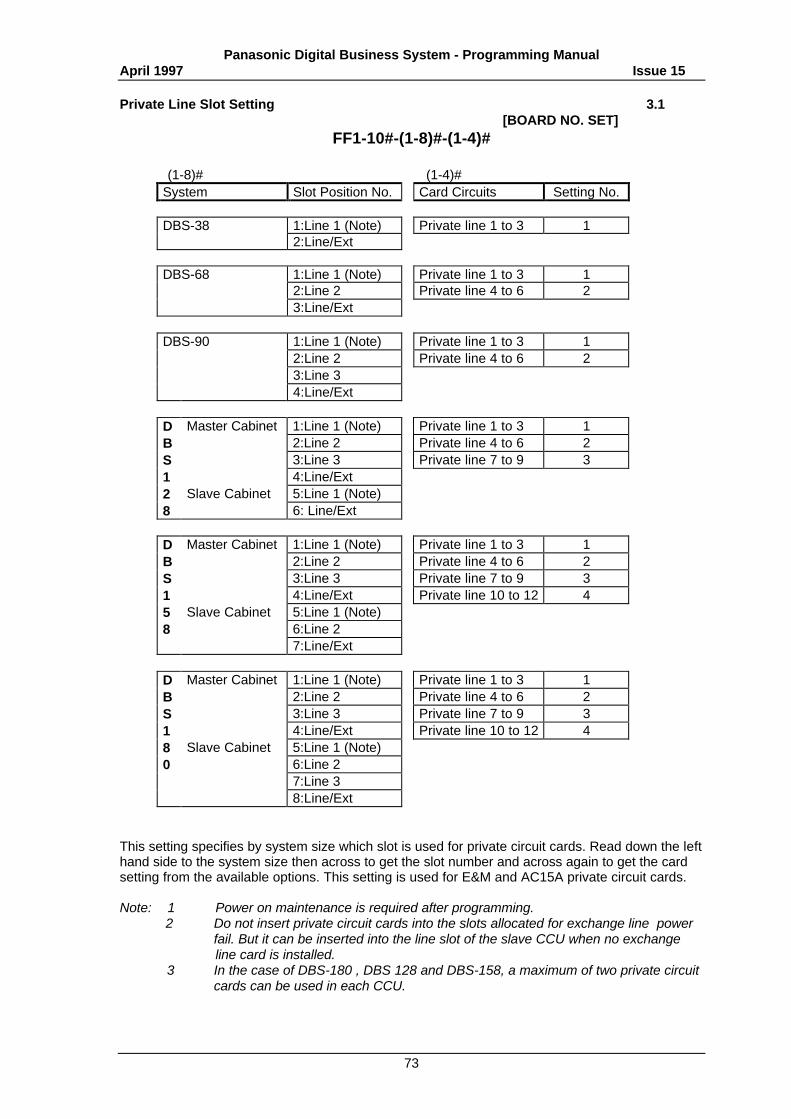
Panasonic Digital Business System - Programming ManualApril 1997 Issue 15
73
Private Line Slot Setting 3.1[BOARD NO. SET]
FF1-10#-(1-8)#-(1-4)#
(1-8)# (1-4)#System Slot Position No. Card Circuits Setting No.
DBS-38 1:Line 1 (Note) Private line 1 to 3 12:Line/Ext
DBS-68 1:Line 1 (Note) Private line 1 to 3 12:Line 2 Private line 4 to 6 23:Line/Ext
DBS-90 1:Line 1 (Note) Private line 1 to 3 12:Line 2 Private line 4 to 6 23:Line 34:Line/Ext
D Master Cabinet 1:Line 1 (Note) Private line 1 to 3 1B 2:Line 2 Private line 4 to 6 2S 3:Line 3 Private line 7 to 9 31 4:Line/Ext2 Slave Cabinet 5:Line 1 (Note)8 6: Line/Ext
D Master Cabinet 1:Line 1 (Note) Private line 1 to 3 1B 2:Line 2 Private line 4 to 6 2S 3:Line 3 Private line 7 to 9 31 4:Line/Ext Private line 10 to 12 45 Slave Cabinet 5:Line 1 (Note)8 6:Line 2
7:Line/Ext
D Master Cabinet 1:Line 1 (Note) Private line 1 to 3 1B 2:Line 2 Private line 4 to 6 2S 3:Line 3 Private line 7 to 9 31 4:Line/Ext Private line 10 to 12 48 Slave Cabinet 5:Line 1 (Note)0 6:Line 2
7:Line 38:Line/Ext
This setting specifies by system size which slot is used for private circuit cards. Read down the lefthand side to the system size then across to get the slot number and across again to get the cardsetting from the available options. This setting is used for E&M and AC15A private circuit cards.
Note: 1 Power on maintenance is required after programming. 2 Do not insert private circuit cards into the slots allocated for exchange line power
fail. But it can be inserted into the line slot of the slave CCU when no exchangeline card is installed.
3 In the case of DBS-180 , DBS 128 and DBS-158, a maximum of two private circuitcards can be used in each CCU.
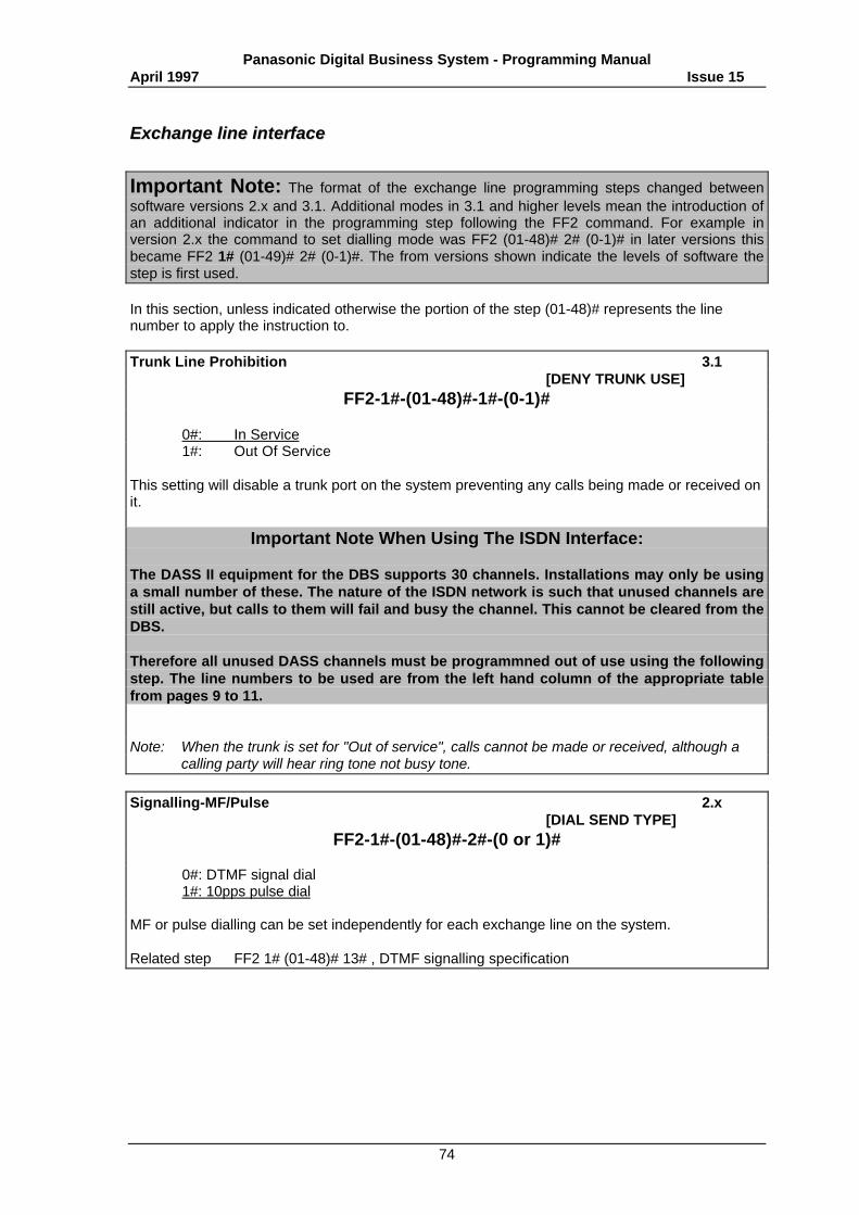
Panasonic Digital Business System - Programming ManualApril 1997 Issue 15
74
EExxcchhaannggee lliinnee iinntteerrffaaccee
Important Note: The format of the exchange line programming steps changed betweensoftware versions 2.x and 3.1. Additional modes in 3.1 and higher levels mean the introduction ofan additional indicator in the programming step following the FF2 command. For example inversion 2.x the command to set dialling mode was FF2 (01-48)# 2# (0-1)# in later versions thisbecame FF2 1# (01-49)# 2# (0-1)#. The from versions shown indicate the levels of software thestep is first used.
In this section, unless indicated otherwise the portion of the step (01-48)# represents the linenumber to apply the instruction to.
Trunk Line Prohibition 3.1[DENY TRUNK USE]
FF2-1#-(01-48)#-1#-(0-1)#
0#: In Service1#: Out Of Service
This setting will disable a trunk port on the system preventing any calls being made or received onit.
Important Note When Using The ISDN Interface:
The DASS II equipment for the DBS supports 30 channels. Installations may only be usinga small number of these. The nature of the ISDN network is such that unused channels arestill active, but calls to them will fail and busy the channel. This cannot be cleared from theDBS.
Therefore all unused DASS channels must be programmned out of use using the followingstep. The line numbers to be used are from the left hand column of the appropriate tablefrom pages 9 to 11.
Note: When the trunk is set for "Out of service", calls cannot be made or received, although acalling party will hear ring tone not busy tone.
Signalling-MF/Pulse 2.x[DIAL SEND TYPE]
FF2-1#-(01-48)#-2#-(0 or 1)#
0#: DTMF signal dial1#: 10pps pulse dial
MF or pulse dialling can be set independently for each exchange line on the system.
Related step FF2 1# (01-48)# 13# , DTMF signalling specification
Panasonic Digital Business System - Programming ManualApril 1997 Issue 15
75
Line Group 0 2.x[MCO GROUP ‘0’]
FF2-1#-(01-48)#-3#-(0 or 1)#
0#: Not subject to line group 01#: Accessible through line group 0
This program allocates which lines are available to line group 0. these lines are accessed bydialling "9". Lines which are allocated to this group can be sub divided into tenant groups to allowmultiple department systems to have each department access their own lines when members dial‘9’.
Note: A line already defined as Dedicated Line to an extension cannot be put in the Groups.
Related steps FF2 1# (01-48)# 25# , Exchange line tenant group settingFF3 (001-144)# 36# , Extension tenant group setting
Line groupings 2.x[MCO GROUP ‘1’-’6’]
FF2-1#-(01-48)#-(4-9)#-(0 or 1)#
(4-9)# (0-1)#4#: Line group 1 0#: Not subject to line group5#: Line group 2 1#: Accessible through line group6#: Line group 37#: Line group 48#: Line group 59#: Line group 6
Sets which exchange lines are available to which line group or groups. A line group can beselected for dialling using the command 81 followed by the group number (1-6).
Note: A line already defined as Dedicated Line to an extension cannot be put in the Groups.
Piggy backing to PBX 2.x[TRUNK TYPE]
FF2-1#-(01-48)#-10#-(0 or 1)#
0#: Exchange line1#: PBX line
This step determines the line type of each exchange line port. When the system is configured as asubsidiary to a host PBX set this to ‘PBX line’ for the system to handle PBX access codes,pauses, recall signals ,and call barring settings correctly.
Panasonic Digital Business System - Programming ManualApril 1997 Issue 15
76
Dedicated line to extension 2.x[PRIVATE PORT#]
FF2-1#-(01-48)#-11#-(001-144)#
[CONF]#: No dedicated line to extension(001-144)#: Dedicated line for set extension port number
Each extension can have an exclusive dedicated line. An incoming call from an exchange line setfor private use rings on the extension to which that line belongs only. While there can be a numberof dedicated lines belonging to one telephone, a single dedicated line cannot belong to a numberof telephones. Once set, other extensions can not make calls to or receive calls from thatexchange line port.
Note: Before you assign a line as a dedicated line to an extension, remove it from all LineGroups.
Auto pause for PBX working 2.x[AUTO PAUSE]
FF2-1#-(01-48)#-12#-(0 or 1)#
0#: No Auto pause1#: Auto pause used
When piggy backing a pause may to be set for each PBX line if required by the host..Related step FF2-1#-(01-48)#-10# , Piggy backing to PBX
FF1-3#-15# , REDIAL/PBX auto pause time
DTMF Signalling Specification 2.x[TONE SEND TIME]
FF2-1#-(01-48)#-13#-(0-1)#
0#: 125 ms ON/125ms OFF1#: 250 ms ON/250ms OFF
This step allows the duration of DTMF tone sent from the system to be lengthened. This may berequired if dial up services requiring further user commands have difficulty detecting the DTMFtones dialled from the system.
Choice of incoming ringing signal 2.x[INCOME TONE PTN]
FF2-1#-(01-48)#-14#-(0-3)#
0#: Incoming ring tone synchronised1#: 0.375 sec ON/0.25 sec OFF/0.375 sec ON/2 sec OFF2#: 1 sec ON/2 sec OFF3#: 0.25 sec ON/0.25 sec OFF/0.25 sec ON/0.25 sec OFF/0.25 sec ON/4.75 sec OFF
The ring tone cadence for incoming calls can be selected for each trunk port. If exchange lines areassigned for use by individuals, they will know who the call is for by the ring tone pattern.
Panasonic Digital Business System - Programming ManualApril 1997 Issue 15
77
Auto line disconnect time 2.x[DISCONNECT TIME]
FF2-1#-(01-48)#-15#-(0 -15)#
0#: No Loop down signal1#: Loop down signal after 50 ms2#: Loop down signal after 100 ms3#: Loop down signal after 150 ms4#: Loop down signal after 200 ms5#: Loop down signal after 250 ms6#: Loop down signal after 300 ms7#: Loop down signal after 350 ms8#: Loop down signal after 400 ms9#: Loop down signal after 450 ms10#: Loop down signal after 500 ms11#: Loop down signal after 550 ms12#: Loop down signal after 600 ms13#: Loop down signal after 650 ms14#: Loop down signal after 700 ms15#: Loop down signal after 750 ms
This specifies the pause time before sending out the LOOP DOWN signal to cut off an exchangeline when the line is busy or exchange line call is on hold following reception of an externaldisconnect signal.
Note: Setting this step to 1 will allow the DBS to recognise Calling Party Clear (CPC) signals fromthe exchange. This should be set when the Voice Announce Unit is installed on the linesringing to the VAU. Otherwise the VAU will not clear down correctly if a caller hangs up.
Note: CPC is not available on all exchanges
Type of PBX recall signal 2.x[FLASH TIMED SET]
FF2-1#-(01-48)#-16#-(0-2)#
0#: No recall1#: Enable time break2#: Enable earth recall
This sets each exchange line to time break, earth or no recall.
Related step FF1 3# 16# , Exchange line disconnect time REDIAL/flashFF1 3# 17# , PBX recall time - earth recallFF1 3# 18# , PBX recall time - time break recall
Panasonic Digital Business System - Programming ManualApril 1997 Issue 15
78
Call logging start time 2.x[CONNECT TIMER]
FF2-1#-(01-48)#-17#-(0-15)#
0#: No time interval set1#: 2 secs after dialling.2#: 4 secs.3#: 6 secs.4#: 8 secs.5#: 10 secs.6#: 12 secs.7#: 14 secs.8#: 16 secs.9#: 18 secs.10#: 20 secs.11#: 22 secs.12#: 24 secs.13#: 26 secs.14#: 28 secs.15#: 30 secs.
This specifies how soon after dialling the system starts to time an exchange line call and displaythe elapsed call time on a display keyset.
FF2-1#-(01-48)#-18# [NOT USED]
FF2-1#-(01-48)#-19#- [NOT USED]
DISA (Direct Inward System Access) line setting 2.x[ENABLE DISA]
FF2-1#-(01-48)#-20#-(0 or 1)
0#: DISA disabled1#: DISA enabled
This specifies whether a line port is a DISA line or standard PSTN line for incoming calls.Outgoing calls can made on the line as normal subject to call barring.
Related steps FF2 1# (01-48)# 21# , DISA auto start timeFF2 1# (01-48)# 22# , DISA auto finish timeFF1 2# 1# 30# , Un answered DISA call transferFF1 2# 1# 31# , # key feature in DISA callFF1 3# 26# , DISA inter-signal timeFF1 3# 27# , DISA no answer timerFF1 3# 30# , DISA cut timer
DISA auto start time 2.x[DISA START TIME]
FF2-1#-(01-48)#-21#-(0000-2359)#
[CONF]#: Clear start time: 0000(0000-2359)#: DISA function start time (24 hour)
This sets a start time for DISA working. DISA calls received prior to the DISA auto start time willbe handled as an ordinary line call.
Related step FF2 1# (01-48)# 20# , DISA line settingFF2 1# (01-48)# 22# , DISA auto finish time
Panasonic Digital Business System - Programming ManualApril 1997 Issue 15
79
DISA auto finish time 2.x[DISA END TIME]
FF2-1#-(01-48)#-22#-(0000-2359)#
[CONF]#: Clear finish time: 2359(0000-2359)#: DISA function finish time (24 hour)
This sets a finish time for DISA working. DISA calls received after the DISA auto finish time will behandled as an ordinary line call.
Related step FF2 1# (01-48)# 20# , DISA line settingFF2 1# (01-48)# 21# , DISA auto start time
External relay control - Exchange line setting for LRB (Loud Ringing Bell) 2.x[EPI CNTRL SET]
FF2-1#-(01-48)#-23#-(0 or 1)#
0#: External relay control and LRB are not set1#: External relay control and LRB are set
Sets which exchange lines are monitored by the LRB function.
Related step FF1 2# 1# 24# , External relay control
Dial tone detection 2.x[D/T DETECTION]
FF2-1#-(01-48)#-24#-(0 or 1)#
0#: DT detection not required.1#: DT detection required.
This sets whether dial tone detection is required before the system sends dialling digits.
Exchange line tenant group setting 3.1[SP. MCO TENANT]
FF2-1#-(01-48)#-25#-(0 or 8)#
1#: Tenant No.12#: Tenant No.23#: Tenant No.34#: Tenant No.45#: Tenant No.56#: Tenant No.67#: Tenant No.78#: Tenant No.8
This is specifies the Tenant Group number. for each outside line which is allocated to line Group0. When ‘9’ is dialled, a free line from the designated Tenant Group is seized automatically.
Related steps FF2 1# (01-48)# 3# , Line group 0FF3 (001-144)# 36# , Extension tenant group setting
Panasonic Digital Business System - Programming ManualApril 1997 Issue 15
80
E&M Dial tone send 3.1[I/C DIAL TONE]
FF2-2#-(1-3)#-1#-(0-1)#
(1-3)# (0-1)#E&M Group Number 0#: Dial tone not sent
1#: Dial tone sent
This setting specifies whether or not to send internal dial tone out across a network connection.
Related step FF2 3# (1-8)# 2# , E&M trunk group number
E&M tenant group 3.1[TENANT GROUP NO]
FF2-2#-(1-3)#-2#-(1-8)#
(1-3)# (1-8)#E&M group number 1#: Tenant group 1
2#: Tenant group 23#: Tenant group 34#: Tenant group 45#: Tenant group 56#: Tenant group 67#: Tenant group 78#: Tenant group 8
This step specifies the tenant group to use when an incoming E&M call requests and outside line.
Related step FF2 1# (01-48)# 25# , Exchange line tenant group setting
E&M Send RAC 3.1[DIAL DELETE]
FF2-2#-(1-3)#-3#-(0-1)#
(1-3)# (0-1)#E&M trunk group 0#: Send RAC
1#: Do not send RAC
Specifies whether or not to send out the route access code (RAC) as the first digit of the numberdialled when making an E&M call. This setting is for use when connecting to a system which is nota DBS and does not require the RAC.
E&M Add RAC 3.1[DIAL INSERT]
FF2-2#-(1-3)#-4#-(0-1)#
(1-3)# (0-1)#E&M trunk group 0#: Do not add RAC
1#: Add RAC
Specifies whether or not to add the route access code (RAC) of the system as the first digit to thereceived digits from an E&M circuit. This is for use when the remote system is not a DBS anddoes not send the RAC.
Panasonic Digital Business System - Programming ManualApril 1997 Issue 15
81
E&M paging release timer 3.1[NET PAG RELEASE]
FF2-2#-(1-3)#-5#-(0-6)#
(1-3)# (0-6)#E&M trunk group 0#: Not used
1#: 30 seconds2#: 60 seconds3#: 90 seconds4#: 120 seconds5#: 150 seconds6#: 180 seconds
Sets the time in seconds to release the E&M circuit when paging. This timer only takes effect if thepaging call goes unanswered and prevents the circuit from being kept unnecessarily busy.
E&M minimum pause 3.1[MIN INTERDIGIT]
FF2-2#-(1-3)#-6#-(0-7)#
(1-3)# (0-7)#E&M trunk group 0#: 300 msec
1#: 400 msec2#: 500 msec3#: 600 msec4#: 700 msec5#: 800 msec6#: 900 msec7#: 1000 msec
Sets the minimum pause between dial pulses when making an E&M call. The default setting is forDBS to DBS connection and may require adjustment when the remote system is not a DBS.
E&M return confirmation monitor 3.1[RELEASE ACK TIM]
FF2-2#(1-3)#-7#-(0-7)#
(1-3)# (0-7)#E&M trunk group 0#: 1 second
1#: 2 seconds2#: 3 seconds3#: 4 seconds4#: 5 seconds5#: 6 seconds6#: 7 seconds7#: 8 seconds
Sets the interval between sending out the release signal to the other party and receiving therelease acknowledge signal after ending an internal call via the E&M Card.
Panasonic Digital Business System - Programming ManualApril 1997 Issue 15
82
E&M return detect timer 3.1[RELEASE(E&M)]
FF2-2#-(1-3)#-8#-(0-15)#
(1-3)# (0-15)#E&M trunk group 0#: 100 msec
1#: 150 msec2#: 200 msec3#: 250 msec4#: 300 msec5#: 350 msec6#: 400 msec7#: 500 msec8#: 600 msec9#: 800 msec10#: 1000 msec11#: 1100 msec12#: 1300 msec13#: 1700 msec14#: 2300 msec15#: 3500 msec
This sets the time to detect the release signal
E&M anti collision timer 3.1[GLARE (E&M)]
FF2-2#-(1-3)#-9#-(0-15)#
(1-3)# (0-15)#E&M trunk group 0#: 10 msec
1#: 15 msec2#: 20 msec3#: 25 msec4#: 30 msec5#: 35 msec6#: 40 msec7#: 45 msec8#: 50 msec9#: 60 msec10#: 70 msec11#: 80 msec12#: 90 msec13#: 100 msec14#: 110 msec15#: 120 msec
This sets the time after E&M seizure in which both sending and receiving are prohibited to avoidcall collision between systems.
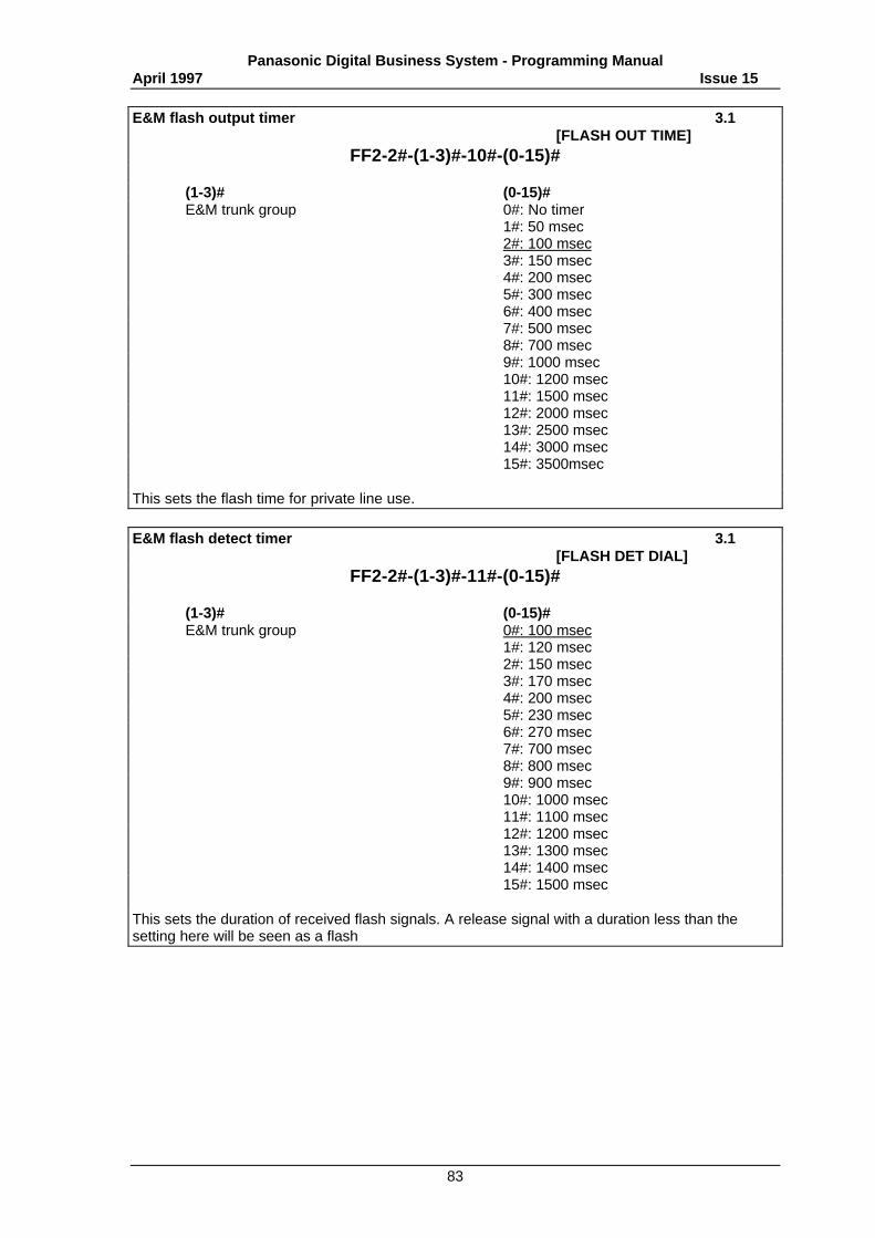
Panasonic Digital Business System - Programming ManualApril 1997 Issue 15
83
E&M flash output timer 3.1[FLASH OUT TIME]
FF2-2#-(1-3)#-10#-(0-15)#
(1-3)# (0-15)#E&M trunk group 0#: No timer
1#: 50 msec2#: 100 msec3#: 150 msec4#: 200 msec5#: 300 msec6#: 400 msec7#: 500 msec8#: 700 msec9#: 1000 msec10#: 1200 msec11#: 1500 msec12#: 2000 msec13#: 2500 msec14#: 3000 msec15#: 3500msec
This sets the flash time for private line use.
E&M flash detect timer 3.1[FLASH DET DIAL]
FF2-2#-(1-3)#-11#-(0-15)#
(1-3)# (0-15)#E&M trunk group 0#: 100 msec
1#: 120 msec2#: 150 msec3#: 170 msec4#: 200 msec5#: 230 msec6#: 270 msec7#: 700 msec8#: 800 msec9#: 900 msec10#: 1000 msec11#: 1100 msec12#: 1200 msec13#: 1300 msec14#: 1400 msec15#: 1500 msec
This sets the duration of received flash signals. A release signal with a duration less than thesetting here will be seen as a flash
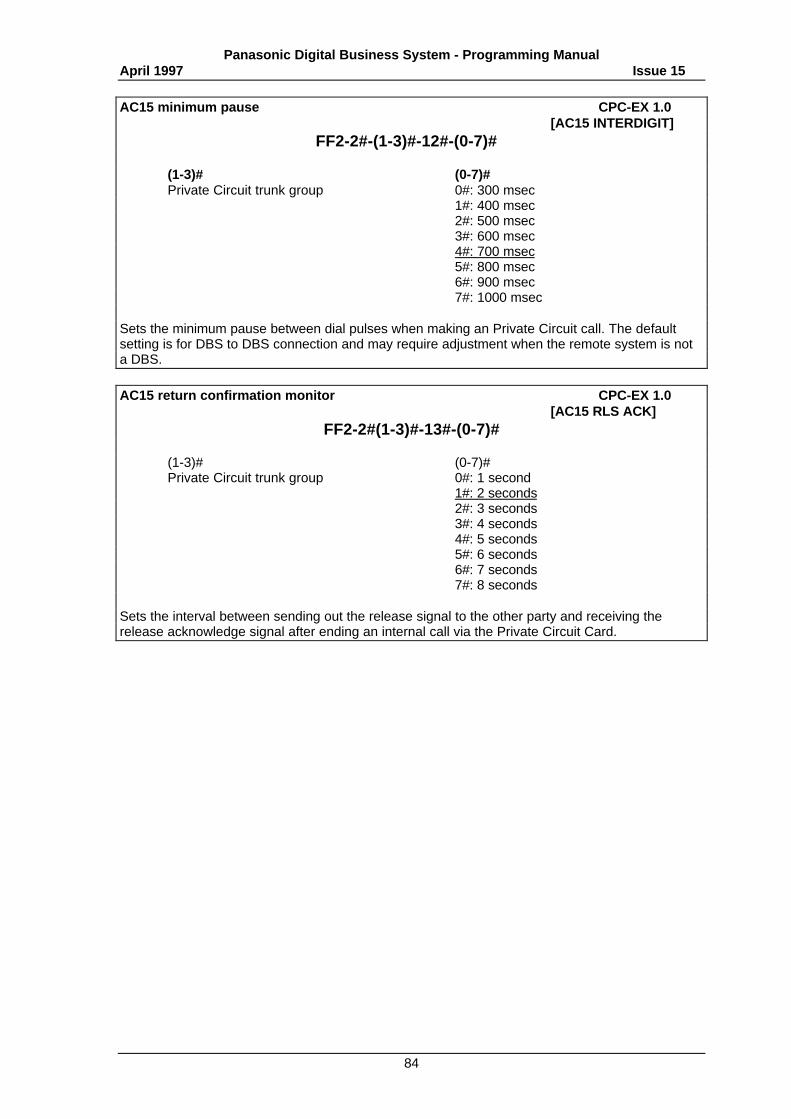
Panasonic Digital Business System - Programming ManualApril 1997 Issue 15
84
AC15 minimum pause CPC-EX 1.0[AC15 INTERDIGIT]
FF2-2#-(1-3)#-12#-(0-7)#
(1-3)# (0-7)#Private Circuit trunk group 0#: 300 msec
1#: 400 msec2#: 500 msec3#: 600 msec4#: 700 msec5#: 800 msec6#: 900 msec7#: 1000 msec
Sets the minimum pause between dial pulses when making an Private Circuit call. The defaultsetting is for DBS to DBS connection and may require adjustment when the remote system is nota DBS.
AC15 return confirmation monitor CPC-EX 1.0[AC15 RLS ACK]
FF2-2#(1-3)#-13#-(0-7)#
(1-3)# (0-7)#Private Circuit trunk group 0#: 1 second
1#: 2 seconds2#: 3 seconds3#: 4 seconds4#: 5 seconds5#: 6 seconds6#: 7 seconds7#: 8 seconds
Sets the interval between sending out the release signal to the other party and receiving therelease acknowledge signal after ending an internal call via the Private Circuit Card.
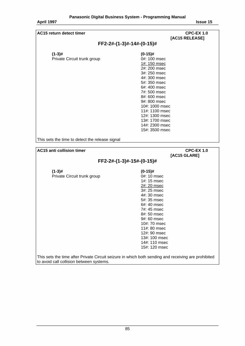
Panasonic Digital Business System - Programming ManualApril 1997 Issue 15
85
AC15 return detect timer CPC-EX 1.0[AC15 RELEASE]
FF2-2#-(1-3)#-14#-(0-15)#
(1-3)# (0-15)#Private Circuit trunk group 0#: 100 msec
1#: 150 msec2#: 200 msec3#: 250 msec4#: 300 msec5#: 350 msec6#: 400 msec7#: 500 msec8#: 600 msec9#: 800 msec10#: 1000 msec11#: 1100 msec12#: 1300 msec13#: 1700 msec14#: 2300 msec15#: 3500 msec
This sets the time to detect the release signal
AC15 anti collision timer CPC-EX 1.0[AC15 GLARE]
FF2-2#-(1-3)#-15#-(0-15)#
(1-3)# (0-15)#Private Circuit trunk group 0#: 10 msec
1#: 15 msec2#: 20 msec3#: 25 msec4#: 30 msec5#: 35 msec6#: 40 msec7#: 45 msec8#: 50 msec9#: 60 msec10#: 70 msec11#: 80 msec12#: 90 msec13#: 100 msec14#: 110 msec15#: 120 msec
This sets the time after Private Circuit seizure in which both sending and receiving are prohibitedto avoid call collision between systems.
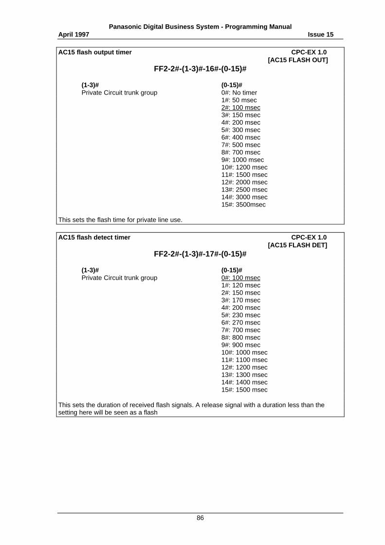
Panasonic Digital Business System - Programming ManualApril 1997 Issue 15
86
AC15 flash output timer CPC-EX 1.0[AC15 FLASH OUT]
FF2-2#-(1-3)#-16#-(0-15)#
(1-3)# (0-15)#Private Circuit trunk group 0#: No timer
1#: 50 msec2#: 100 msec3#: 150 msec4#: 200 msec5#: 300 msec6#: 400 msec7#: 500 msec8#: 700 msec9#: 1000 msec10#: 1200 msec11#: 1500 msec12#: 2000 msec13#: 2500 msec14#: 3000 msec15#: 3500msec
This sets the flash time for private line use.
AC15 flash detect timer CPC-EX 1.0[AC15 FLASH DET]
FF2-2#-(1-3)#-17#-(0-15)#
(1-3)# (0-15)#Private Circuit trunk group 0#: 100 msec
1#: 120 msec2#: 150 msec3#: 170 msec4#: 200 msec5#: 230 msec6#: 270 msec7#: 700 msec8#: 800 msec9#: 900 msec10#: 1000 msec11#: 1100 msec12#: 1200 msec13#: 1300 msec14#: 1400 msec15#: 1500 msec
This sets the duration of received flash signals. A release signal with a duration less than thesetting here will be seen as a flash
Panasonic Digital Business System - Programming ManualApril 1997 Issue 15
87
E&M trunk status 3.1[TRUNK STATUS]
FF2-3#-(1-12)#-1#-(0-1)#
(1-12)# (0-1)#Private circuit number 0#: Used1-3 card 1 1#: Not used4-6 card 27-9 card 310-12 card 4
Determines whether or not a private circuit is used. When a circuit is set to not used the tell-taleLED corresponding to it on the card will remain lit after system start up.
Related step FF1 10# (1-10)# (1-4)# , Slot setting
E&M trunk group number 3.1[TRUNK GROUP NO.]
FF2-3#-(1-12)#-2#-(0-3)#
(1-12)# (0-3)#Private circuit number 0#: Not assigned
1#: Group 12#: Group 23#: Group 3
Assigns private lines to private line groups. Circuits must be assigned to groups as all E&M accessis via group access and not independent circuits.
AC15 Dial Mode CPC-EX 1.0[AC15 DIAL TYPE]
FF2-3#-(1-12)#-3#-(0-1)# (P)
(1-12)# (0-1)#Private Circuit number 0#: DTMF1-3 card 1 1#: Pulse4-6 card 27-9 card 310-12 card 4
The dialling type for AC15 lines can be set to tone or pulse using this step. If changed a systempower Off/On reset is required. If set for DTMF an DTMF receiver card is required in the CCU.
This step will only take effect if the circuit specified is supported by an AC15 card (VB3673) it hasno effect when E&M cards are installed.
Panasonic Digital Business System - Programming ManualApril 1997 Issue 15
88
AC15 DTMF Specification CPC-EX 1.0[AC15 DIAL TIME]
FF2-3#-(1-12)#-4#-(0-1)#
(1-12)# (0-1)#Private Circuit number 0#: 125ms/125ms1-3 card 1 1#: 250ms/250ms4-6 card 27-9 card 310-12 card 4
This step sets the ON/OFF times for the DTMF signals when dialling on AC15.
This step will only take effect if the circuit specified is supported by an AC15 card (VB3673) it hasno effect when E&M cards are installed.
Panasonic Digital Business System - Programming ManualApril 1997 Issue 15
89
EExxtteennssiioonn ffeeaattuurreess
This section covers the setting of extension features. Unless otherwise specified (001-144)# ineach step represents the extension port number to which the command is to apply.
Extension number 2.x[EXT# NN(NN)]
FF3-(001-144)#-1#-(NNNN)#
[CONF]#: No setting(20-59)#: 2 digits number (20, 21 for operators)(200-599)#: 3 digits number (200, 201 for operators)(2000-5900)#: 2 digits number (2000, 2001 for operators)
This step specifies the extension number to be allocated to a specified port. The extension numberset must correspond to the number of digits specified in system programming. If there are morethan 40 extensions connected to the system, extension numbers with 3 or 4 digits must be used.If DSS units are connected, it is not necessary to store extension numbers for them. If operatorsare used they must connected to ports 1 and 2 and be the first extension numbers.
Note: A extension number cannot be used twice. If a number cannot be stored check that it isnot allocated to another extension port. If it is use CONF# to clear it from the other portthen re- store it in the required location.
Type of extension 2.x / 3.2 / 4.0 / CPC-EX 1.0 / CPC-EX v1.5[TEL TYPE SET]
FF3-(001-144)#-2#-(1-15)# CPC-B & CFF3-(001-144)#-2#-(1-24)# CPC-EX 1.0
(1-144)# (1-24)#Extension Port 1# Analogue
2# VB3011 Digital SLT3# VB3411 / VB3411D / VB3411DS4# VB3611D / VB3611DS
` 5# VBD3411 / VBD3411DS6# VBD3611D / VBD3611DS7# - 9# Reserved10# Voicemail Port11# DSS 1 for 1st operator12# DSS 2 for 1st operator13# DSS 1 for 2nd operator14# DSS 2 for 2nd operator15# - 16# Reserved17# 12 Key VBD Keyset18# 24 Key VBD Keyset19# Reserved20# E-ISDN 3.1Khz Modem21# BLF DSS 122# BLF DSS 223# BLF DSS 324# BLF DSS 4
The basic extension types are automatically sensed when the system is turned on. Some morespecialist ones require setting manually. These are DSS & BLF DSS consoles and voicemail ports, this arises because these ports have specialist functions and operations associated with themand their location within the system is not fixed.Note: When programming DSS, it is necessary either to turn the system power off and then turn
it on again, or to disconnect the module jacks for the DSS and then reinsert them.
Panasonic Digital Business System - Programming ManualApril 1997 Issue 15
90
FF3-(001-144)#-3# [NOT USED]
Forced Account code 3.1[FORCED ACC. CODE]
FF3-(001-144)#-4#-(0 or 1)#
0#: No need to input Account code to make an outside call1#: Need to input Account code to make an outside call
In situations where all calls must be allocated against an account this step will prevent anextension making an outgoing call unless an account number is entered first.
Extension lock-code registration 2.x[LOCK OUT CODE]
FF3-(001-144)#-5#-(0000-9999)#
[CONF]#: No extension lock function(0000-9999)#: Extension lock key code
A lock code can be stored for each extension, when this done the extension can be locked bydialling 74. When locked the extension can only make internal calls and outgoing call allowed byits locked class of service. It can be unlocked by 74 and the lock code stored here.
Related step FF7 1# 17# , Extension class of service when locked
Off-hook signalling 2.x[CO OFF-HK SIGNL]
FF3-(001-144)#-6#-(0 or 1)#
0#: No off hook signalling1#: Off hook signalling set
Each extension can be set to receive exchange line off hook signalling while busy.
Note: Off hook signalling when set will not function during conference calls, whilst the extensionis on hold or when using a non appearing (No line key) exchange line.
Related step FF3-(001-144)#-15#, Off Hook Signalling Volume
Call waiting tone and message 2.x[CALL WAITING]
FF3-(001-144)#-7#-(0 or 1)#
0#: Call waiting disabled1#: Call waiting enabled
This specifies whether or not an extension can receive call waiting tones and messages whenbusy.
Note: Call waiting tones will not be received when the extension is on hold, receiving a call, inconference or if "Absence" has been set.
Panasonic Digital Business System - Programming ManualApril 1997 Issue 15
91
Busy override (call intrusion) - originating 2.x[BUSY OVERRIDE]
FF3-(001-144)#-8#-(0 or 1)#
0#: Break in not allowed1#: Break in allowed
This sets whether an extension can originate a break in call or not.
Note: Busy override is not possible when the destination extension is set to reject it or by anextension involved in a conference call.
Busy override (call intrusion) - receiving 2.x[BUSY OVERRIDEN]
FF3-(001-144)#-9#-(0 or 1)#
0#: Break in call is rejected1#: Break in call is accepted
This sets whether an extension can receive a break in call or not.
Break in-operator call intrusion 2.x[ATT OVERRIDEN]
FF3-(001-144)#-10#-(0 or 1)#
0#: Operator break in is rejected1#: Break in is accepted.
This sets whether to accept break in from the operator or to reject it.
FF3-(001-144)#-11# [NOT USED]
Prime line pick-up (auto exchange line seizure) 2.x[PRIME LINE]
FF3-(001-144)#-12#-(0 or 1)#
0#: No prime line function1#: To pick up prime line
It is possible to program an extension to seize an exchange line when the handset is lifted.The exchange line to be used has to be programmed under the FF1 key. If line group access hasbeen set under the FF1 key, the highest available line in the group is selected.
Note: When prime line pick up is set for an extension, that extension must have an intercom keyset to enable intercom calls to be made. (See FF Key Assignment).
Panasonic Digital Business System - Programming ManualApril 1997 Issue 15
92
Auto answer 2.x[AUTO ANSWER]
FF3-(001-144)#-13#-(0 or 1)#
0#: Auto answer disabled1#: Auto answer enabled
When set the longest ringing call assigned to the extension is automatically answered when theextension goes off hook.
Note: This function will only operate with calls that are assigned to ring at the extension and callstransferred to it. If the extension is not set to ring no calls will be answered even if otherextensions are ringing.
Note: Ports used for Voice Annouce Units require auto answer enabled.
Call logging printout-exchange lines 2.x[SMDR PRINT Y/N]
FF3-(001-144)#-14#-(0 or 1)#
0#: Information from exchange line calls not printed out by call logger / printer1#: Information from exchange line calls printed out by call logger / printer
This sets whether information from exchange line calls made by the extension are to be output tothe call logging interface. This allow calls from selected extensions to be kept private.
Off-hook signalling volume level 2.x[I TONE VOLUME]
FF3-(001-144)#-15#-(1-4)#
1#: minimum2#: normal3#: middle4#: maximum
The Off-hook signalling tone can be set by extension to 4 different levels.
Note: A soft reset (switch system off and back on) is required after changing this step.
Call waiting tone ringing cadence 2.x[OFF-HK SIG PTN]
FF3-(001-144)#-16#-(0 or 1)#
0#: Call Waiting signal is sent out until the call is answered1#: Call Waiting signal is sent out once only
Personal Speed Dial (PSD) directory display 2.x[PSD DISP. MODE]
FF3-(001-144)#-17#-(0 or 1)#
0#: List 5 PSD names at one time1#: List 10 PSD names at one time
For key telephones with large display, a choice can be made to display either 5 or 10 personalspeed dial (PSD) names at one time under the ‘Personal Dial’ menu option.
Panasonic Digital Business System - Programming ManualApril 1997 Issue 15
93
Paging Group Assignment 2.x[PAGE GRPUP (#00-#07)]
FF3-(001-144)#-(18-25)#-(0 or 1)#
(18-25)# (0-1)#18#: Paging group 0 0#: Not a member19#: Paging group 1 1#: Is a member20#: Paging group 221#: Paging group 322#: Paging group 423#: Paging group 524#: Paging group 625#: Paging group 7
This step is used to assign extensions to paging groups. In default all extensions are in group 0.Extensions can belong to multiple paging groups.
Large display key station - display options 2.x[DISPLAY ON IDLE][DISPLAY ON IDT][DISPLAY ON INT][DISPLAY ON CO-1][DISPLAY ON CO-2][DISPLAY ON PAGE][DISPLAY ON WAIT][DISPLAY ON BUSY]
FF3-(001-144)#-(26-33)#-(0-15)#
(26-33)# (0-15)#26#: Idle mode 0#: No change27#: Internal dial tone 1#: Menu information28#: Internal call 2#: Personal speed dial index29#: External call before duration displayed 3#: System speed dial index30#: External call after duration displayed 4#: Extension index31#: Receiving paging call 5#: Guidance menu 132#: Receiving call waiting tone 6#: Guidance menu 233#: Receiving busy tone 7#: Guidance menu 3
8#: Guidance menu 49#: Guidance menu 510#: Guidance menu 611#: Guidance menu 712#: Function 113#: Function 214#: Function 315#: Function 4
This step sets the display screen to show on a large display key handset when it’s operating modematches that specified above left to the display specified above right. each extension can haveone display option specified for each mode. This will allow the most appropriate screen to bedisplayed automatically as the phone is used.
Panasonic Digital Business System - Programming ManualApril 1997 Issue 15
94
Analogue extension time break recall time 2.x[SLT HOOK FLASH]
FF3-(001-144)#-34#-(0-13)#
0#: Less than 20 ms 200-500 ms over 500 ms1#: Less than 20 ms 200-750 ms over 750 ms2#: Less than 20 ms 200-1000 ms over 1000 ms3#: Less than 20 ms 200-1200 ms over 1500 ms4#: Less than 20 ms 200-1500 ms over 200 ms5#: Less than 20 ms over 200 ms6#: Less than 20 ms 30-150 ms over 200 ms7#: Less than 20 ms 60-150 ms over 200 ms8#: Less than 20 ms 65-150 ms over 200 ms9#: Less than 20 ms 70-150 ms over 200 ms10#: Less than 20 ms 75-150 ms over 200 ms11#: Less than 20 ms 80-150 ms over 200 ms12#: Less than 20 ms 85-150 ms over 200 ms
This sets the time break recall time for analogue extensions. This step is useful to match the timebreak recall time generated by connected analogue equipment if problems are encountered usingrecall. The default setting is suitable for the majority of installations. This step has no effect on theoperation of digital extensions.
System speed dial (SSD) group selection 2.x[1:SSD-1 2:SSD-2]
FF3-(001-144)#-35#-(1 or 2)#
1#: SSD group 12#: SSD group 2
This specifies which group of system speed dials the extension has access too. The SSDs aredivided into two groups of 90 numbers. Each extension can have access to either group 1 or group2.
Extension tenant group setting 3.1[SP. MCO TENANT]
FF3-(001-144)#-36#-(1-8)#
1#: Tenant No.12#: Tenant No.23#: Tenant No.34#: Tenant No.45#: Tenant No.56#: Tenant No.67#: Tenant No.78#: Tenant No.8
This is specifies the tenant group number for each extension. A tenant group is a sub group oflines available to line group 0. When ‘9’ is dialled, a free line from the designated tenant group isseized automatically.
Related steps FF2 1# (01-48)# 3# , Line group assignment - group 0FF2 1# (01-48)# 25# , Exchange line tenant group setting
Panasonic Digital Business System - Programming ManualApril 1997 Issue 15
95
Extension Off Hook Monitor CPC-EX 1.0
FF3 (1-144)# 37# (0-1)#
(1-144)# (0-1)#Extension port 0# Disabled
1# Enabled
The extension off hook monitor facility of the VBD handsets can be individually switched on or offfor each extension. When enabled and extension user who presses the On/Off key when on a callwill hear the call via the speaker and handset at the same time.
Incoming Ringing Volume Setting CPC-EX 1.0
FF3 (1-144)# 38# (0-1)#
(1-144)# (0-1)#Extension port 0# Disabled
1# Enabled
The extension incoming ring volume facility of the VBD handsets can be individually switched onor off for each extension.
Monitor Volume Setting CPC-EX 1.0
FF3 (1-144)# 39# (0-1)#
(1-144)# (0-1)#Extension port 0# Disabled
1# Enabled
The extension monitor volume facility of the VBD handsets can be individually switched on or offfor each extension.
Call Forward To External Number CPC-EX 1.0
FF3 (1-144)# 40# (0-1)#
(1-144)# (0-1)#Extension port number 0# Not allowed
1# Allowed
This step can bar or allow an extension to set call forward to an external number.
Panasonic Digital Business System - Programming ManualApril 1997 Issue 15
96
Assignment Of Extension To Work With BLF DSS CPC-EX 1.0
FF3 (1-144)# 41# (0-4)#
(1-144)# (0-4)#Extension Port 0# No BLF DSS associated
1# Works with BLF DSS 12# Works with BLF DSS 23# Works with BLF DSS 34# Works with BLF DSS 4
The BLF DSS uses the existing DSS console as an extended BLF unit which can be assigned towork with any non-operator key station. The BLF DSS will not operate in conjunction with theVB3011 or an SLT and any keyset can only have 1 BLF DSS unit associated with it. Up to foursuch BLF DSS units can be assigned for the system. This is in addition to the Operator positionswhich can still have 2 fully functioning DSS consoles at each of the two Operator positions as withprevious software versions.
When used as a keyset BLF DSS the console will operate only as a BLF. Single key transfer willoperate, but extension pick up will not be supported.
On Hook Transfer To Trunk CPC-EX v1.5
FF3 (1-144)# 42# (0-1)#
0# Disabled1# Enabled
Transferring of calls to outgoing trunks can be disabled for extension users who do not require orare not permitted to use this feature.
Related Step: FF1 2# 5# - Cross Connection Permissions
Panasonic Digital Business System - Programming ManualApril 1997 Issue 15
97
RRiinnggiinngg aassssiiggnnmmeenntt
This section contains the programming steps which control the ringing of calls within the system.Unless otherwise specified (001-144)# represents the extension port number and (01-48)#represents the line port number.
Incoming ring - Day mode 2.x[DAY RING SET]
FF4-1#-(001-144)#-(01-48)#-(0 or 1)#
0#: No Ring1#: Rings
This sets which exchange lines ring on which extensions when in day mode.
Note: By default, operator telephones ring for all incoming exchange lines
Incoming ring - Night mode 2.x[NIGHT RING SET]
FF4-2#-(001-144)#-(01-48)#-(0 or 1)#
0#: No Ring1#: Rings
This sets which exchange lines ring on which extensions when in night mode.
Note: By default, operator telephones ring for all incoming exchange lines.
Related step FF1-3#-1# , Auto night mode
Incoming ring - Operator overflow / Delayed Ringing 2.x[ATT OV RING SET]
FF4-3#-(001-144)#-(01-48)#-(0 or 1)#
0#: No Ring1#: Rings
This step specifies the ring pattern to use when the operator overflow or delayed ringing functionsare active.
Related step FF1 2# 1# 15# , Operator call overflowFF1 2# 1# 26# , Delayed ringing
Panasonic Digital Business System - Programming ManualApril 1997 Issue 15
98
Type of hunt group 2.x[HUNTING MODE]
FF4-4#-(1-16)#-1#-(0 or 1)#
(1-16)# (0-1)#Hunt group number 0#: Terminate
1#: Circular
An incoming call to an extension within the hunt group which is busy, it is automatically transferredaccording to the order laid down in the hunt group table. The system supports 16 different huntgroups. There are two types of hunt group.
1) Circular: An incoming call to any extension within the hunt group which is busy willautomatically be transferred to the next extension in the hunt group table.
2) Terminal: A call to member number 1 in the hung group will be automatically transferred tothe next free extension in the hunt group. If the last group member is busy the callis terminated and the caller will receive busy tone. Call to other members of thegroup will not hunt.
Note1: An incoming exchange line which rings a busy hunt group will hear ringing and not busy.Note2: An extension can only belong to a single hunt group or single coverage group.
Hunt group transfer 2.x[NEXT HUNT GROUP]
FF4-4#-(1-16)#-2#-(1-16)# From To
To cancel the feature input [CONF]key.
If all the extensions in one hunting group are busy, the incoming call can be automaticallytransferred to another hunt group. A hunt group into which automatic transfer is actually operatingcannot receive a call from a further hunt group.
Hunt group assignment to extension 2.x[MEMBER EXT.#]
FF4-4#-(1-16)#-(3-10)#-(Ext No.)#
(1-16)# (3-10)# (Ext No.)#Hunt Group Number 3#: Member 1 Extension Number
4#: Member 2 Conf# to clear stored number5#: Member 36#: Member 47#: Member 58#: Member 69#: Member 710#: Member 8
A maximum of 8 extensions can belong to each hunt group. An incoming call to the group, istransferred to the first free extension according to the order in which the extensions are stored.An extension can only belong to one hunt group or one coverage group and cannot be storedmore than once. If an entry is rejected check that it has not been stored against another group.
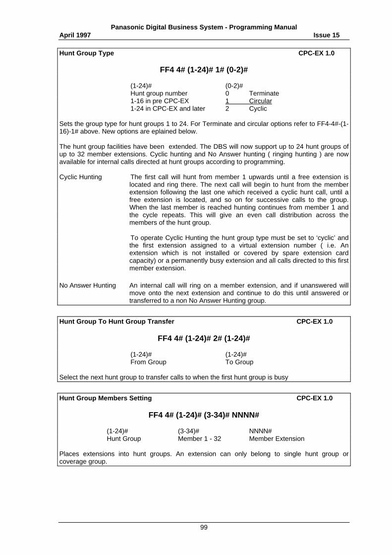
Panasonic Digital Business System - Programming ManualApril 1997 Issue 15
99
Hunt Group Type CPC-EX 1.0
FF4 4# (1-24)# 1# (0-2)#
(1-24)# (0-2)#Hunt group number 0 Terminate1-16 in pre CPC-EX 1 Circular1-24 in CPC-EX and later 2 Cyclic
Sets the group type for hunt groups 1 to 24. For Terminate and circular options refer to FF4-4#-(1-16)-1# above. New options are eplained below.
The hunt group facilities have been extended. The DBS will now support up to 24 hunt groups ofup to 32 member extensions. Cyclic hunting and No Answer hunting ( ringing hunting ) are nowavailable for internal calls directed at hunt groups according to programming.
Cyclic Hunting The first call will hunt from member 1 upwards until a free extension islocated and ring there. The next call will begin to hunt from the memberextension following the last one which received a cyclic hunt call, until afree extension is located, and so on for successive calls to the group.When the last member is reached hunting continues from member 1 andthe cycle repeats. This will give an even call distribution across themembers of the hunt group.
To operate Cyclic Hunting the hunt group type must be set to ‘cyclic’ andthe first extension assigned to a virtual extension number ( i.e. Anextension which is not installed or covered by spare extension cardcapacity) or a permanently busy extension and all calls directed to this firstmember extension.
No Answer Hunting An internal call will ring on a member extension, and if unanswered willmove onto the next extension and continue to do this until answered ortransferred to a non No Answer Hunting group.
Hunt Group To Hunt Group Transfer CPC-EX 1.0
FF4 4# (1-24)# 2# (1-24)#
(1-24)# (1-24)#From Group To Group
Select the next hunt group to transfer calls to when the first hunt group is busy
Hunt Group Members Setting CPC-EX 1.0
FF4 4# (1-24)# (3-34)# NNNN#
(1-24)# (3-34)# NNNN#Hunt Group Member 1 - 32 Member Extension
Places extensions into hunt groups. An extension can only belong to single hunt group orcoverage group.
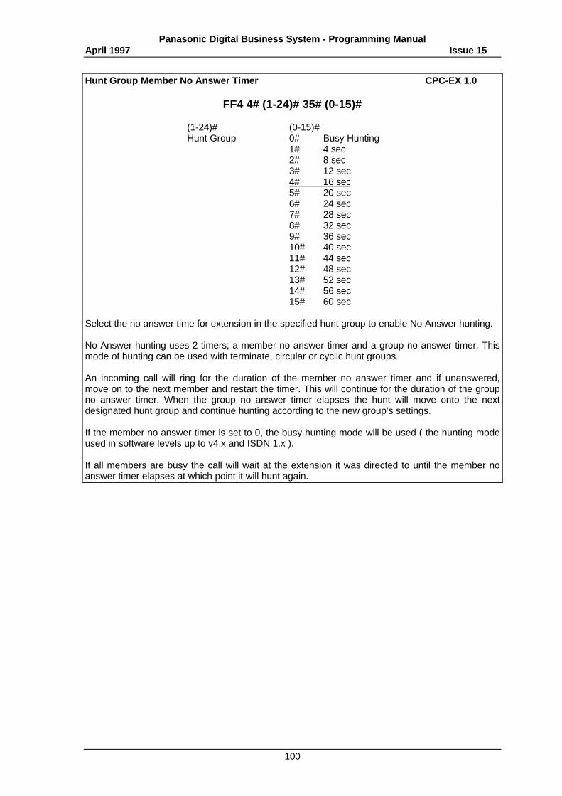
Panasonic Digital Business System - Programming ManualApril 1997 Issue 15
100
Hunt Group Member No Answer Timer CPC-EX 1.0
FF4 4# (1-24)# 35# (0-15)#
(1-24)# (0-15)#Hunt Group 0# Busy Hunting
1# 4 sec2# 8 sec3# 12 sec4# 16 sec5# 20 sec6# 24 sec7# 28 sec8# 32 sec9# 36 sec10# 40 sec11# 44 sec12# 48 sec13# 52 sec14# 56 sec15# 60 sec
Select the no answer time for extension in the specified hunt group to enable No Answer hunting.
No Answer hunting uses 2 timers; a member no answer timer and a group no answer timer. Thismode of hunting can be used with terminate, circular or cyclic hunt groups.
An incoming call will ring for the duration of the member no answer timer and if unanswered,move on to the next member and restart the timer. This will continue for the duration of the groupno answer timer. When the group no answer timer elapses the hunt will move onto the nextdesignated hunt group and continue hunting according to the new group’s settings.
If the member no answer timer is set to 0, the busy hunting mode will be used ( the hunting modeused in software levels up to v4.x and ISDN 1.x ).
If all members are busy the call will wait at the extension it was directed to until the member noanswer timer elapses at which point it will hunt again.
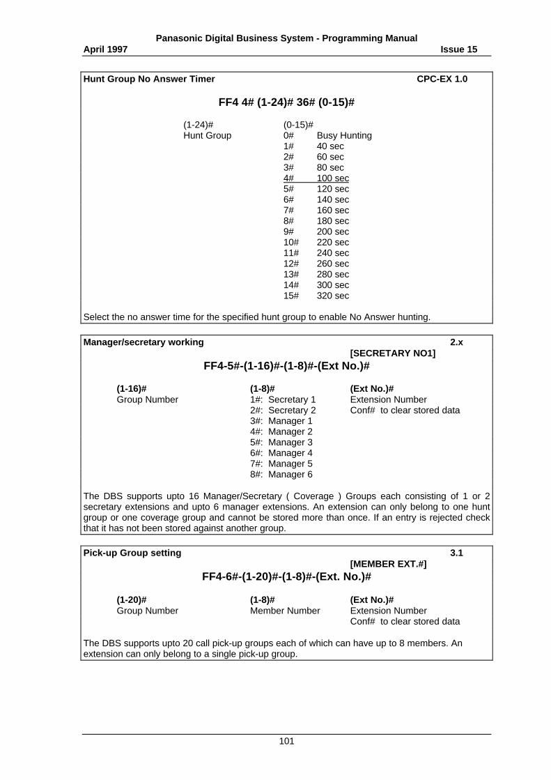
Panasonic Digital Business System - Programming ManualApril 1997 Issue 15
101
Hunt Group No Answer Timer CPC-EX 1.0
FF4 4# (1-24)# 36# (0-15)#
(1-24)# (0-15)#Hunt Group 0# Busy Hunting
1# 40 sec2# 60 sec3# 80 sec4# 100 sec5# 120 sec6# 140 sec7# 160 sec8# 180 sec9# 200 sec10# 220 sec11# 240 sec12# 260 sec13# 280 sec14# 300 sec15# 320 sec
Select the no answer time for the specified hunt group to enable No Answer hunting.
Manager/secretary working 2.x[SECRETARY NO1]
FF4-5#-(1-16)#-(1-8)#-(Ext No.)#
(1-16)# (1-8)# (Ext No.)#Group Number 1#: Secretary 1 Extension Number
2#: Secretary 2 Conf# to clear stored data3#: Manager 14#: Manager 25#: Manager 36#: Manager 47#: Manager 58#: Manager 6
The DBS supports upto 16 Manager/Secretary ( Coverage ) Groups each consisting of 1 or 2secretary extensions and upto 6 manager extensions. An extension can only belong to one huntgroup or one coverage group and cannot be stored more than once. If an entry is rejected checkthat it has not been stored against another group.
Pick-up Group setting 3.1[MEMBER EXT.#]
FF4-6#-(1-20)#-(1-8)#-(Ext. No.)#
(1-20)# (1-8)# (Ext No.)#Group Number Member Number Extension Number
Conf# to clear stored data
The DBS supports upto 20 call pick-up groups each of which can have up to 8 members. Anextension can only belong to a single pick-up group.
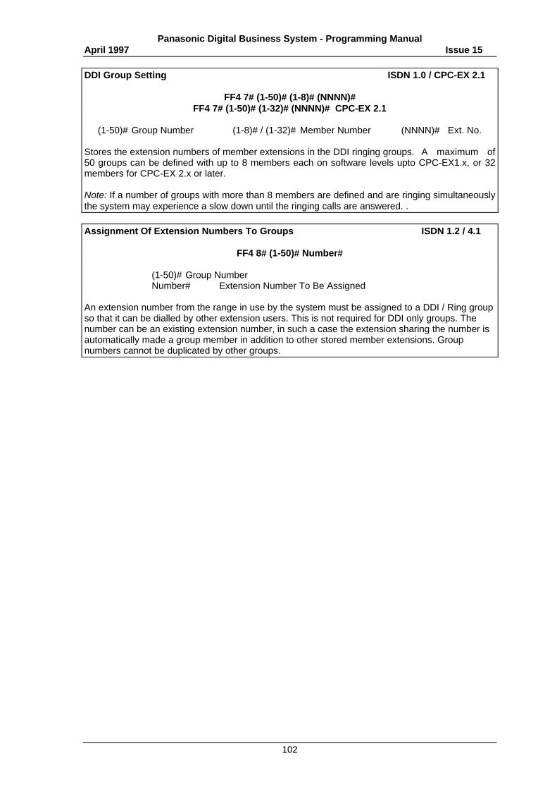
Panasonic Digital Business System - Programming ManualApril 1997 Issue 15
102
DDI Group Setting ISDN 1.0 / CPC-EX 2.1
FF4 7# (1-50)# (1-8)# (NNNN)#FF4 7# (1-50)# (1-32)# (NNNN)# CPC-EX 2.1
(1-50)# Group Number (1-8)# / (1-32)# Member Number (NNNN)# Ext. No.
Stores the extension numbers of member extensions in the DDI ringing groups. A maximum of50 groups can be defined with up to 8 members each on software levels upto CPC-EX1.x, or 32members for CPC-EX 2.x or later.
Note: If a number of groups with more than 8 members are defined and are ringing simultaneouslythe system may experience a slow down until the ringing calls are answered. .
Assignment Of Extension Numbers To Groups ISDN 1.2 / 4.1
FF4 8# (1-50)# Number#
(1-50)# Group NumberNumber# Extension Number To Be Assigned
An extension number from the range in use by the system must be assigned to a DDI / Ring groupso that it can be dialled by other extension users. This is not required for DDI only groups. Thenumber can be an existing extension number, in such a case the extension sharing the number isautomatically made a group member in addition to other stored member extensions. Groupnumbers cannot be duplicated by other groups.
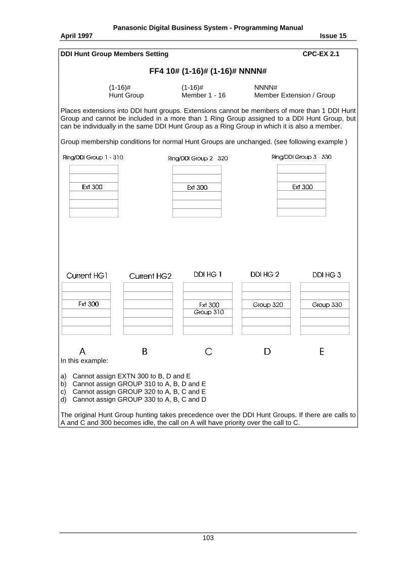
Panasonic Digital Business System - Programming ManualApril 1997 Issue 15
103
DDI Hunt Group Members Setting CPC-EX 2.1
FF4 10# (1-16)# (1-16)# NNNN#
(1-16)# (1-16)# NNNN#Hunt Group Member 1 - 16 Member Extension / Group
Places extensions into DDI hunt groups. Extensions cannot be members of more than 1 DDI HuntGroup and cannot be included in a more than 1 Ring Group assigned to a DDI Hunt Group, butcan be individually in the same DDI Hunt Group as a Ring Group in which it is also a member.
Group membership conditions for normal Hunt Groups are unchanged. (see following example )
In this example:
a) Cannot assign EXTN 300 to B, D and Eb) Cannot assign GROUP 310 to A, B, D and Ec) Cannot assign GROUP 320 to A, B, C and Ed) Cannot assign GROUP 330 to A, B, C and D
The original Hunt Group hunting takes precedence over the DDI Hunt Groups. If there are calls toA and C and 300 becomes idle, the call on A will have priority over the call to C.
Panasonic Digital Business System - Programming ManualApril 1997 Issue 15
104
DDI Hunt Group Member No Answer Timer CPC-EX 2.1
FF4 10# (1-16)# 17# (0-15)#
(1-16)# (0-15)#Hunt Group 0# Busy Hunting
1# 4 sec2# 8 sec3# 12 sec4# 16 sec5# 20 sec6# 24 sec7# 28 sec8# 32 sec9# 36 sec10# 40 sec11# 44 sec12# 48 sec13# 52 sec14# 56 sec15# 60 sec
Select the no answer time for extension in the specified DDI hunt group to enable No Answerhunting.
An incoming call will ring for the duration of the member no answer timer and if unanswered,move on to the next member and restart the timer.
If the member no answer timer is set to 0, the busy hunting mode will be used ( the hunting modeused in software levels up to v4.x and ISDN 1.x ).
If all members are busy the call will wait at the extension it was directed to until the member noanswer timer elapses at which point it will hunt again.
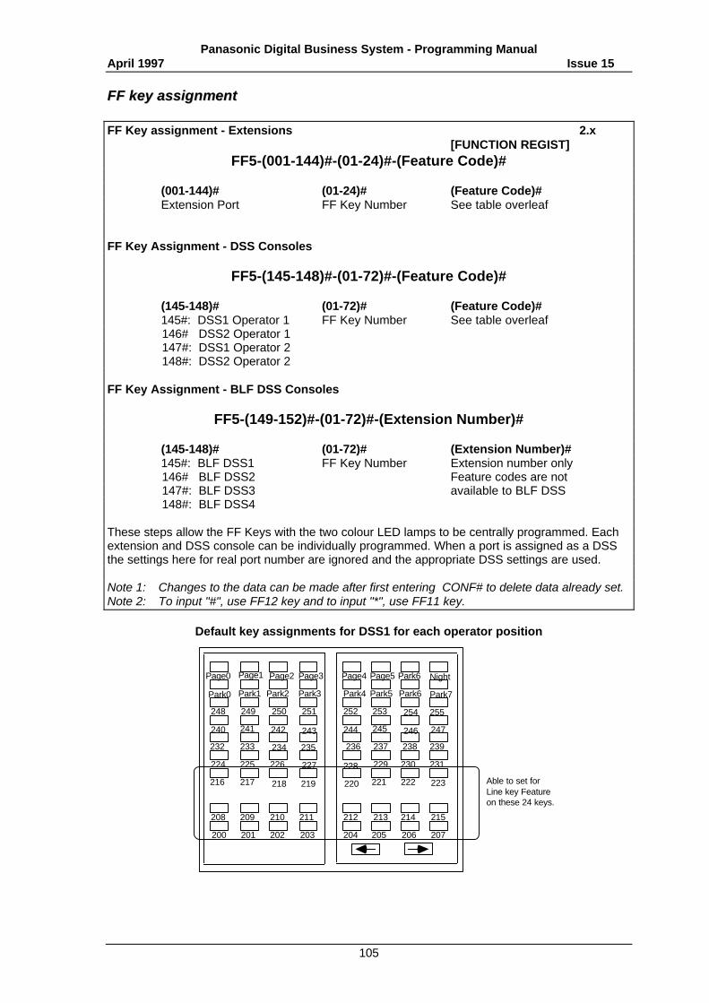
Panasonic Digital Business System - Programming ManualApril 1997 Issue 15
105
FFFF kkeeyy aassssiiggnnmmeenntt
FF Key assignment - Extensions 2.x[FUNCTION REGIST]
FF5-(001-144)#-(01-24)#-(Feature Code)#
(001-144)# (01-24)# (Feature Code)#Extension Port FF Key Number See table overleaf
FF Key Assignment - DSS Consoles
FF5-(145-148)#-(01-72)#-(Feature Code)#
(145-148)# (01-72)# (Feature Code)#145#: DSS1 Operator 1 FF Key Number See table overleaf 146# DSS2 Operator 1 147#: DSS1 Operator 2 148#: DSS2 Operator 2
FF Key Assignment - BLF DSS Consoles
FF5-(149-152)#-(01-72)#-(Extension Number)#
(145-148)# (01-72)# (Extension Number)#145#: BLF DSS1 FF Key Number Extension number only 146# BLF DSS2 Feature codes are not 147#: BLF DSS3 available to BLF DSS 148#: BLF DSS4
These steps allow the FF Keys with the two colour LED lamps to be centrally programmed. Eachextension and DSS console can be individually programmed. When a port is assigned as a DSSthe settings here for real port number are ignored and the appropriate DSS settings are used.
Note 1: Changes to the data can be made after first entering CONF# to delete data already set.Note 2: To input "#", use FF12 key and to input "*", use FF11 key.
Default key assignments for DSS1 for each operator position
200
208
201
209
202
210
203
211
204
212
216
224
232
240
248
Park0
Page0
205
213
206
214
207
215
223
231
239
247
255
Park7
NightPark6Page1
Park1
249
241
233
225
217 218
226
234
242
250
Park2
Page2
219
227
235
243
251
Park3
Page3
220
228
236
244
252
Park4
Page4
221
229
237
245
253
Park5
Page5
222
230
238
246
254
Park6
Able to set for Line key Feature on these 24 keys.
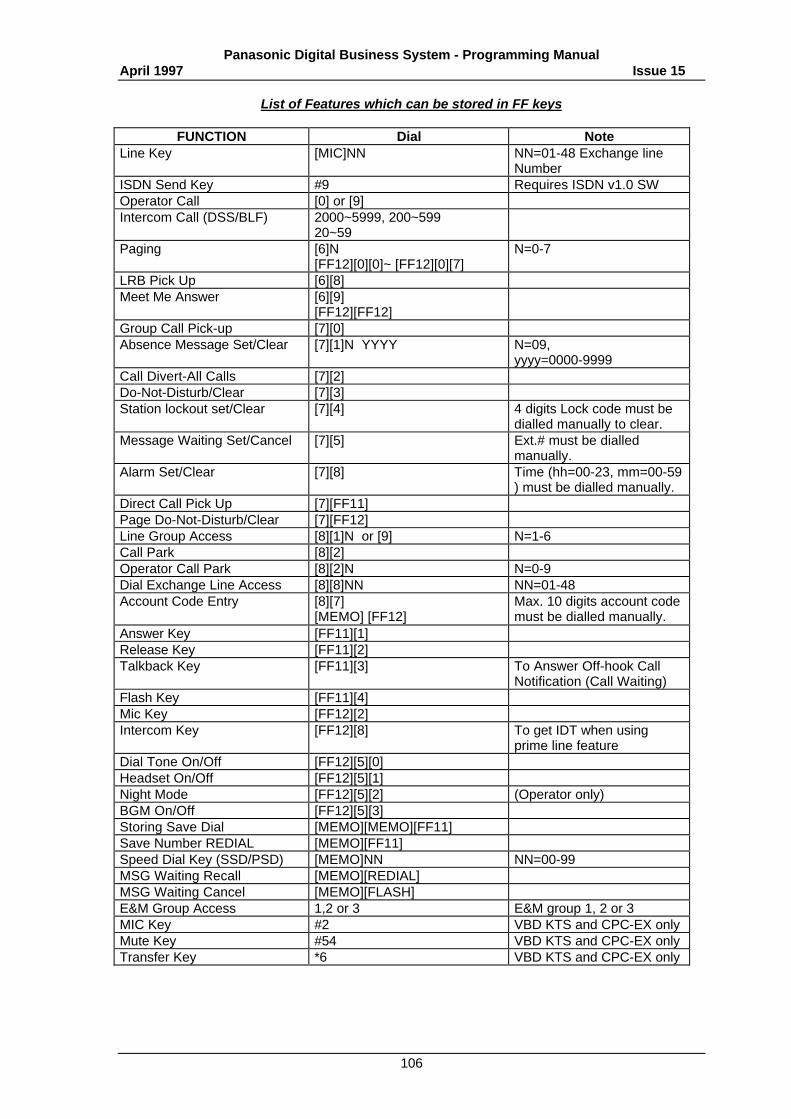
Panasonic Digital Business System - Programming ManualApril 1997 Issue 15
106
List of Features which can be stored in FF keys
FUNCTION Dial NoteLine Key [MIC]NN NN=01-48 Exchange line
NumberISDN Send Key #9 Requires ISDN v1.0 SWOperator Call [0] or [9]Intercom Call (DSS/BLF) 2000~5999, 200~599
20~59Paging [6]N
[FF12][0][0]~ [FF12][0][7]N=0-7
LRB Pick Up [6][8]Meet Me Answer [6][9]
[FF12][FF12]Group Call Pick-up [7][0]Absence Message Set/Clear [7][1]N YYYY N=09,
yyyy=0000-9999Call Divert-All Calls [7][2]Do-Not-Disturb/Clear [7][3]Station lockout set/Clear [7][4] 4 digits Lock code must be
dialled manually to clear.Message Waiting Set/Cancel [7][5] Ext.# must be dialled
manually.Alarm Set/Clear [7][8] Time (hh=00-23, mm=00-59
) must be dialled manually.Direct Call Pick Up [7][FF11]Page Do-Not-Disturb/Clear [7][FF12]Line Group Access [8][1]N or [9] N=1-6Call Park [8][2]Operator Call Park [8][2]N N=0-9Dial Exchange Line Access [8][8]NN NN=01-48Account Code Entry [8][7]
[MEMO] [FF12]Max. 10 digits account codemust be dialled manually.
Answer Key [FF11][1]Release Key [FF11][2]Talkback Key [FF11][3] To Answer Off-hook Call
Notification (Call Waiting)Flash Key [FF11][4]Mic Key [FF12][2]Intercom Key [FF12][8] To get IDT when using
prime line featureDial Tone On/Off [FF12][5][0]Headset On/Off [FF12][5][1]Night Mode [FF12][5][2] (Operator only)BGM On/Off [FF12][5][3]Storing Save Dial [MEMO][MEMO][FF11]Save Number REDIAL [MEMO][FF11]Speed Dial Key (SSD/PSD) [MEMO]NN NN=00-99MSG Waiting Recall [MEMO][REDIAL]MSG Waiting Cancel [MEMO][FLASH]E&M Group Access 1,2 or 3 E&M group 1, 2 or 3MIC Key #2 VBD KTS and CPC-EX onlyMute Key #54 VBD KTS and CPC-EX onlyTransfer Key *6 VBD KTS and CPC-EX only
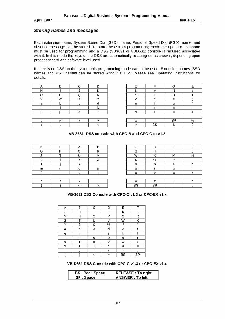
Panasonic Digital Business System - Programming ManualApril 1997 Issue 15
107
SSttoorriinngg nnaammeess aanndd mmeessssaaggeess
Each extension name, System Speed Dial (SSD) name, Personal Speed Dial (PSD) name, andabsence message can be stored. To store these from programming mode the operator telephonemust be used for programming and a DSS (VB3631 or VBD631) console is required associatedwith it. In this mode the keys of the DSS are automatically re-assigned as shown , depending uponprocessor card and software level used..
If there is no DSS on the system this programming mode cannot be used. Extension names ,SSDnames and PSD names can be stored without a DSS, please see Operating Instructions fordetails.
A B C D E F G &H I J K L M N /O P Q R S T U (V W X Y Z * # )a b c d e f g ‘h I j k l m n -o p q r s t u =
v w x y z _ SP %: . , < > BS $ ?
VB-3631 DSS console with CPC-B and CPC-C to v1.2
K L A B C D E FO P Q R G H I JS T U V W X M Ne f Y Z $ % ? ‘I j k l a b c d
m n o p q r g h# = s t u v w x
: / - . y z ; *( ) < > BS SP _ ,
VB-3631 DSS Console with CPC-C v1.3 or CPC-EX v1.x
A B C D E FG H I J K LM N O P Q RS T U V W XY Z $ % ? ‘a b c d e fg h I j k lm n o p q rs t u v w xy z ; * # =_ , : / - .( ) < > BS SP
VB-D631 DSS Console with CPC-C v1.3 or CPC-EX v1.x
BS : Back Space RELEASE : To rightSP : Space ANSWER : To left
Panasonic Digital Business System - Programming ManualApril 1997 Issue 15
108
Storing extension names 2.x[NNNN INT.NNNN]
FF6-1#-(001-144)#-(Name)#
(001-144)# (Name)#Extension Port Maximum 10 letters
Names can be stored for each of the extension ports. When names are stored for each of theextensions, they will be displayed on key sets with LCD screens when internal calls are made andappear in the extension directory on large display key sets
Storing names for SSD group 1 2.x[SSD XX -SSD XX]
FF6-2#-1#-(00-89)#-(Name)#
(00-89)# (Name)#System speed dial code Maximum 16 letters
This is to store a name for each SSD (system speed dial) code. Storing a name for each SSDcode allows the name to be confirmed when making calls using SSDs the name will be displayedon the lower line of display keysets and will appear in the directory on large display keysets.
Storing name for SSD group 2 2.x[SSD XX -SSD XX]
FF6-2#-2#-(00-89)#-(Name)#
(00-89)# (Name)#System speed dial code Maximum 16 letters
This is to store a name for each SSD (system speed dial) code. Storing a name for each SSDcode allows the name to be confirmed when making calls using SSDs the name will be displayedon the lower line of display keysets and will appear in the directory on large display keysets.
Storing name for personal speed dial 2.x[PSD XX -PSD XX]
FF6-3#-(001-144)#-(90-99)#-(Name)#
(001-144)# (90-99)# (Name)#Extension port PSD Location Maximum 16 letters
Names can be stored for the PSD locations of each extension.
Storing absence messages 2.x[MSG#0 IN MEETING]
FF6-4#-(0-9)#-(Message)#
(0-9)# (Message)#Message number Maximum 15 letters0#: IN MEETING1#: AT LUNCH2#: OUT OF OFFICE3#: HOLIDAY4#: ANOTHER OFFICE
Ten absence messages can be stored for use by extensions. Please see Operating Instructions fordetails regarding the use of absence messaging. The first five are set as indicated but can bechanged.
Panasonic Digital Business System - Programming ManualApril 1997 Issue 15
109
Storing call waiting messages 2.x[C.W#5 VISITOR HERE]
FF6-5#-(5-9)#-(Name)#
(5-9)#: (Message)#Message number Maximum 15 letters
Five call waiting messages can be stored for use when signalling waiting calls to display keysets.Please see Operating Instructions for details about using call waiting messages.
Group Names ISDN v1.2
FF6 6# (1-50)# (NNNNNNNN)#
(1-50)# Group Number (NNNNNNNN)# Group Name (Max 8 characters)Initial Setting GRP01 - GRP50
A name of up to 8 characters can be assigned to each DDI group. Character entry is the same asfor other DBS name storage via programming using the DSS.
Setting Line Names ISDN 1.2 / 4.1
FF6 7# (1-48)# Name#
(1-48)# Trunk numberName# Trunk name (max. 16 characters)
Using the DSS character overlay names can be assigned to trunks. Names can be assigned forboth analogue and ISDN trunks.
Panasonic Digital Business System - Programming ManualApril 1997 Issue 15
110
CCaallll bbaarrrriinngg
The DBS has five classes of call barring which can be assigned by line and extension. Theseclasses can themselves be modified through programming.
Important Note: Some settings will be affected by the National Code Change (NCC) stepfrom version 4:
FF10 (ID Code)# 9# 1# (0-1)#
The defaults for these settings will be annotated NCC when there is difference between the preand post NCC settings.
First digit for STD national call 2.x[SET 1DIGIT NO]
FF7-1#-1#-(0-9)#
(0-9)# First digit of STD code
The first digit for national STD calls must be stored here. Long-distance call barring isimplemented for the following digits when the first digit dialled after the line is seized matches thenumber here.
Note: Initial value is "0".
Code for international dialling 2.x[SET 4DIGIT NO]
FF7-1#--2#-(0-9999)#
(0-9999)#: International code maximum 4 digits
The code for international dialling must be stored here for international call barring to operatecorrectly. International call barring performs its checks on the digits following the internationaldialling code.
Note: The initial value is 010 and changes to 00 post NCC
First digit for operator service 2.x[SET 1DIGIT NO]
FF7-1#-3#-(0-9)#
(0-9)#: First digit of operator services
The first digit of operator service calls must be stored here for the operator service call barring tofunction correctly.
Note: Initial value is 1.
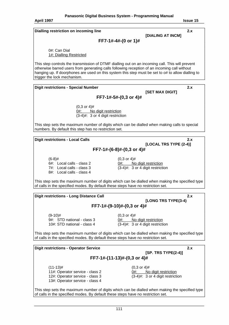
Panasonic Digital Business System - Programming ManualApril 1997 Issue 15
111
Dialling restriction on incoming line 2.x[DIALING AT INCM]
FF7-1#-4#-(0 or 1)#
0#: Can Dial1#: Dialling Restricted
This step controls the transmission of DTMF dialling out on an incoming call. This will preventotherwise barred users from generating calls following reception of an incoming call withouthanging up. If doorphones are used on this system this step must be set to o# to allow dialling totrigger the lock mechanism.
Digit restrictions - Special Number 2.x[SET MAX DIGIT]
FF7-1#-5#-(0,3 or 4)#
(0,3 or 4)#0#: No digit restriction(3-4)#: 3 or 4 digit restriction
This step sets the maximum number of digits which can be dialled when making calls to specialnumbers. By default this step has no restriction set.
Digit restrictions - Local Calls 2.x[LOCAL TRS TYPE (2-4)]
FF7-1#-(6-8)#-(0,3 or 4)#
(6-8)# (0,3 or 4)#6#: Local calls - class 2 0#: No digit restriction7#: Local calls - class 3 (3-4)#: 3 or 4 digit restriction8#: Local calls - class 4
This step sets the maximum number of digits which can be dialled when making the specified typeof calls in the specified modes. By default these steps have no restriction set.
Digit restrictions - Long Distance Call 2.x[LONG TRS TYPE(3-4)
FF7-1#-(9-10)#-(0,3 or 4)#
(9-10)# (0,3 or 4)#9#: STD national - class 3 0#: No digit restriction10#: STD national - class 4 (3-4)#: 3 or 4 digit restriction
This step sets the maximum number of digits which can be dialled when making the specified typeof calls in the specified modes. By default these steps have no restriction set.
Digit restrictions - Operator Service 2.x[SP. TRS TYPE(2-4)]
FF7-1#-(11-13)#-(0,3 or 4)#
(11-13)# (0,3 or 4)#11#: Operator service - class 2 0#: No digit restriction12#: Operator service - class 3 (3-4)#: 3 or 4 digit restriction13#: Operator service - class 4
This step sets the maximum number of digits which can be dialled when making the specified typeof calls in the specified modes. By default these steps have no restriction set.
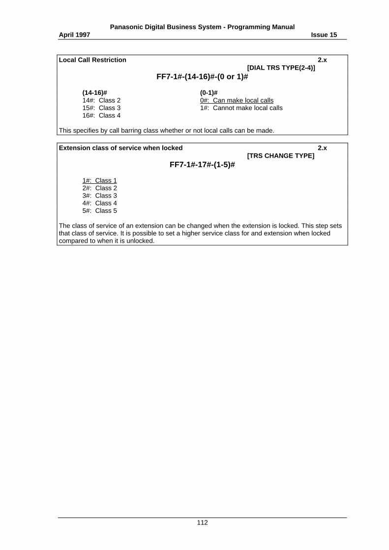
Panasonic Digital Business System - Programming ManualApril 1997 Issue 15
112
Local Call Restriction 2.x[DIAL TRS TYPE(2-4)]
FF7-1#-(14-16)#-(0 or 1)#
(14-16)# (0-1)#14#: Class 2 0#: Can make local calls15#: Class 3 1#: Cannot make local calls16#: Class 4
This specifies by call barring class whether or not local calls can be made.
Extension class of service when locked 2.x[TRS CHANGE TYPE]
FF7-1#-17#-(1-5)#
1#: Class 12#: Class 23#: Class 34#: Class 45#: Class 5
The class of service of an extension can be changed when the extension is locked. This step setsthat class of service. It is possible to set a higher service class for and extension when lockedcompared to when it is unlocked.
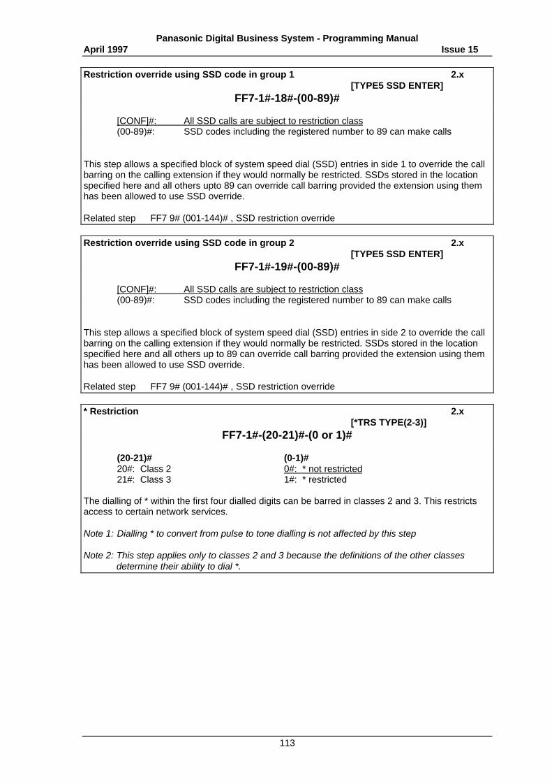
Panasonic Digital Business System - Programming ManualApril 1997 Issue 15
113
Restriction override using SSD code in group 1 2.x[TYPE5 SSD ENTER]
FF7-1#-18#-(00-89)#
[CONF]#: All SSD calls are subject to restriction class(00-89)#: SSD codes including the registered number to 89 can make calls
This step allows a specified block of system speed dial (SSD) entries in side 1 to override the callbarring on the calling extension if they would normally be restricted. SSDs stored in the locationspecified here and all others upto 89 can override call barring provided the extension using themhas been allowed to use SSD override.
Related step FF7 9# (001-144)# , SSD restriction override
Restriction override using SSD code in group 2 2.x[TYPE5 SSD ENTER]
FF7-1#-19#-(00-89)#
[CONF]#: All SSD calls are subject to restriction class(00-89)#: SSD codes including the registered number to 89 can make calls
This step allows a specified block of system speed dial (SSD) entries in side 2 to override the callbarring on the calling extension if they would normally be restricted. SSDs stored in the locationspecified here and all others up to 89 can override call barring provided the extension using themhas been allowed to use SSD override.
Related step FF7 9# (001-144)# , SSD restriction override
* Restriction 2.x[*TRS TYPE(2-3)]
FF7-1#-(20-21)#-(0 or 1)#
(20-21)# (0-1)#20#: Class 2 0#: * not restricted21#: Class 3 1#: * restricted
The dialling of * within the first four dialled digits can be barred in classes 2 and 3. This restrictsaccess to certain network services.
Note 1: Dialling * to convert from pulse to tone dialling is not affected by this step
Note 2: This step applies only to classes 2 and 3 because the definitions of the other classesdetermine their ability to dial *.
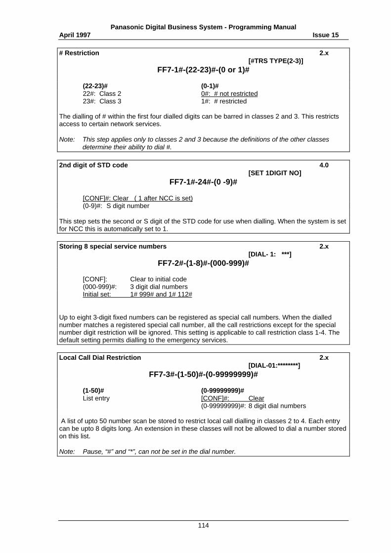
Panasonic Digital Business System - Programming ManualApril 1997 Issue 15
114
# Restriction 2.x[#TRS TYPE(2-3)]
FF7-1#-(22-23)#-(0 or 1)#
(22-23)# (0-1)#22#: Class 2 0#: # not restricted23#: Class 3 1#: # restricted
The dialling of # within the first four dialled digits can be barred in classes 2 and 3. This restrictsaccess to certain network services.
Note: This step applies only to classes 2 and 3 because the definitions of the other classesdetermine their ability to dial #.
2nd digit of STD code 4.0[SET 1DIGIT NO]
FF7-1#-24#-(0 -9)#
[CONF]#: Clear ( 1 after NCC is set)(0-9)#: S digit number
This step sets the second or S digit of the STD code for use when dialling. When the system is setfor NCC this is automatically set to 1.
Storing 8 special service numbers 2.x[DIAL- 1: ***]
FF7-2#-(1-8)#-(000-999)#
[CONF]: Clear to initial code(000-999)#: 3 digit dial numbersInitial set: 1# 999# and 1# 112#
Up to eight 3-digit fixed numbers can be registered as special call numbers. When the diallednumber matches a registered special call number, all the call restrictions except for the specialnumber digit restriction will be ignored. This setting is applicable to call restriction class 1-4. Thedefault setting permits dialling to the emergency services.
Local Call Dial Restriction 2.x[DIAL-01:********]
FF7-3#-(1-50)#-(0-99999999)#
(1-50)# (0-99999999)#List entry [CONF]#: Clear
(0-99999999)#: 8 digit dial numbers
A list of upto 50 number scan be stored to restrict local call dialling in classes 2 to 4. Each entrycan be upto 8 digits long. An extension in these classes will not be allowed to dial a number storedon this list.
Note: Pause, “#” and “*”, can not be set in the dial number.
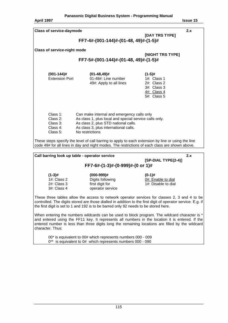
Panasonic Digital Business System - Programming ManualApril 1997 Issue 15
115
Class of service-daymode 2.x[DAY TRS TYPE]
FF7-4#-(001-144)#-(01-48, 49)#-(1-5)#
Class of service-night mode[NIGHT TRS TYPE]
FF7-5#-(001-144)#-(01-48, 49)#-(1-5)#
(001-144)# (01-48,49)# (1-5)#Extension Port 01-48#: Line number 1#: Class 1
49#: Apply to all lines 2#: Class 23#: Class 34#: Class 45#: Class 5
Class 1: Can make internal and emergency calls onlyClass 2: As class 1, plus local and special service calls only.Class 3: As class 2, plus STD national calls.Class 4: As class 3, plus international calls.Class 5: No restrictions
These steps specify the level of call barring to apply to each extension by line or using the linecode 49# for all lines in day and night modes. The restrictions of each class are shown above.
Call barring look up table - operator service 2.x[SP-DIAL TYPE(2-4)]
FF7-6#-(1-3)#-(0-999)#-(0 or 1)#
(1-3)# (000-999)# (0-1)#1#: Class 2 Digits following 0#: Enable to dial2#: Class 3 first digit for 1#: Disable to dial3#: Class 4 operator service
These three tables allow the access to network operator services for classes 2, 3 and 4 to becontrolled. The digits stored are those dialled in addition to the first digit of operator service. E.g. ifthe first digit is set to 1 and 192 is to be barred only 92 needs to be stored here.
When entering the numbers wildcards can be used to block program. The wildcard character is *and entered using the FF11 key. It represents all numbers in the location it is entered. If theentered number is less than three digits long the remaining locations are filled by the wildcardcharacter. Thus:
00* is equivalent to 00# which represents numbers 000 - 0090** is equivalent to 0# which represents numbers 000 - 090
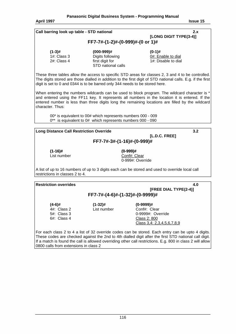
Panasonic Digital Business System - Programming ManualApril 1997 Issue 15
116
Call barring look up table - STD national 2.x[LONG DIGIT TYPE(3-4)]
FF7-7#-(1-2)#-(0-999)#-(0 or 1)#
(1-3)# (000-999)# (0-1)#1#: Class 3 Digits following 0#: Enable to dial2#: Class 4 first digit for 1#: Disable to dial
STD national calls
These three tables allow the access to specific STD areas for classes 2, 3 and 4 to be controlled.The digits stored are those dialled in addition to the first digit of STD national calls. E.g. if the firstdigit is set to 0 and 0344 is to be barred only 344 needs to be stored here.
When entering the numbers wildcards can be used to block program. The wildcard character is *and entered using the FF11 key. It represents all numbers in the location it is entered. If theentered number is less than three digits long the remaining locations are filled by the wildcardcharacter. Thus:
00* is equivalent to 00# which represents numbers 000 - 0090** is equivalent to 0# which represents numbers 000 - 090
Long Distance Call Restriction Override 3.2[L.D.C. FREE]
FF7-7#-3#-(1-16)#-(0-999)#
((11--1166))## ((00--999999))##List number Conf#: Clear
0-999#: Override
A list of up to 16 numbers of up to 3 digits each can be stored and used to override local callrestrictions in classes 2 to 4.
Restriction overrides 4.0[FREE DIAL TYPE(2-4)]
FF7-7#-(4-6)#-(1-32)#-(0-9999)#
(4-6)# (1-32)# (0-9999)#4#: Class 2 List number Conf#: Clear5#: Class 3 0-9999#: Override6#: Class 4 Class 2: 800
Class 3,4: 2,3,4,5,6,7,8,9
For each class 2 to 4 a list of 32 override codes can be stored. Each entry can be upto 4 digits.These codes are checked against the 2nd to 4th dialled digit after the first STD national call digit.If a match is found the call is allowed overriding other call restrictions. E.g. 800 in class 2 will allow0800 calls from extensions in class 2
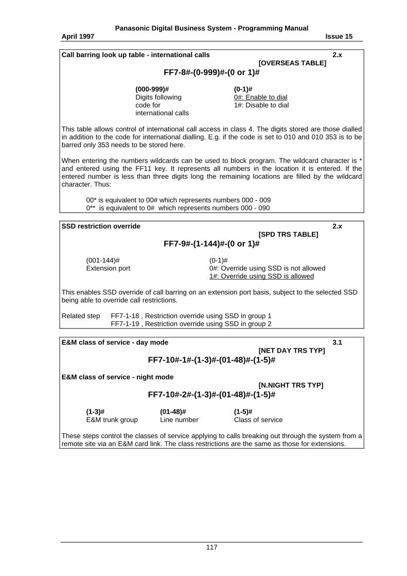
Panasonic Digital Business System - Programming ManualApril 1997 Issue 15
117
Call barring look up table - international calls 2.x[OVERSEAS TABLE]
FF7-8#-(0-999)#-(0 or 1)#
(000-999)# (0-1)#Digits following 0#: Enable to dialcode for 1#: Disable to dialinternational calls
This table allows control of international call access in class 4. The digits stored are those dialledin addition to the code for international dialling. E.g. if the code is set to 010 and 010 353 is to bebarred only 353 needs to be stored here.
When entering the numbers wildcards can be used to block program. The wildcard character is *and entered using the FF11 key. It represents all numbers in the location it is entered. If theentered number is less than three digits long the remaining locations are filled by the wildcardcharacter. Thus:
00* is equivalent to 00# which represents numbers 000 - 0090** is equivalent to 0# which represents numbers 000 - 090
SSD restriction override 2.x[SPD TRS TABLE]
FF7-9#-(1-144)#-(0 or 1)#
(001-144)# (0-1)#Extension port 0#: Override using SSD is not allowed
1#: Override using SSD is allowed
This enables SSD override of call barring on an extension port basis, subject to the selected SSDbeing able to override call restrictions.
Related step FF7-1-18 , Restriction override using SSD in group 1FF7-1-19 , Restriction override using SSD in group 2
E&M class of service - day mode 3.1[NET DAY TRS TYP]
FF7-10#-1#-(1-3)#-(01-48)#-(1-5)#
E&M class of service - night mode[N.NIGHT TRS TYP]
FF7-10#-2#-(1-3)#-(01-48)#-(1-5)#
(1-3)# (01-48)# (1-5)#E&M trunk group Line number Class of service
These steps control the classes of service applying to calls breaking out through the system from aremote site via an E&M card link. The class restrictions are the same as those for extensions.
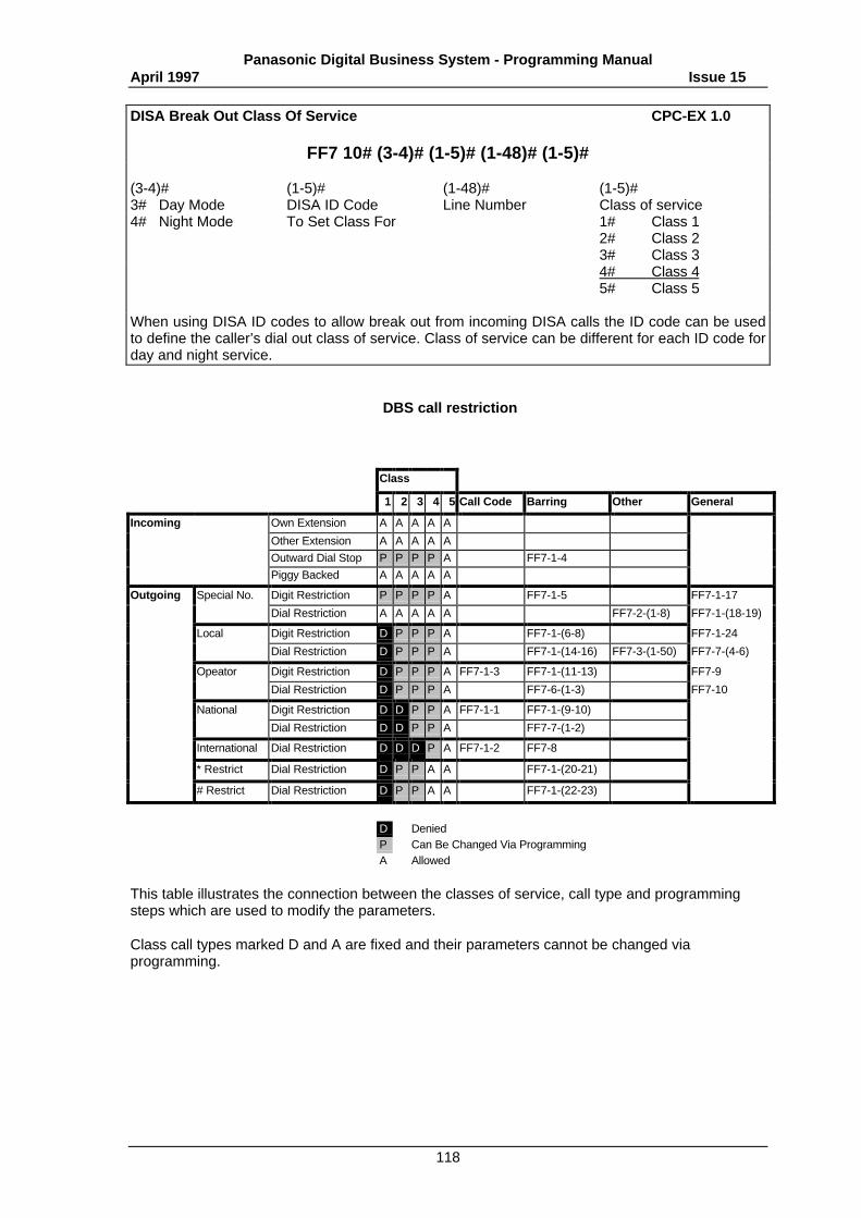
Panasonic Digital Business System - Programming ManualApril 1997 Issue 15
118
DISA Break Out Class Of Service CPC-EX 1.0
FF7 10# (3-4)# (1-5)# (1-48)# (1-5)#
(3-4)# (1-5)# (1-48)# (1-5)#3# Day Mode DISA ID Code Line Number Class of service4# Night Mode To Set Class For 1# Class 1
2# Class 23# Class 34# Class 45# Class 5
When using DISA ID codes to allow break out from incoming DISA calls the ID code can be usedto define the caller’s dial out class of service. Class of service can be different for each ID code forday and night service.
DBS call restriction
Class
1 2 3 4 5 Call Code Barring Other General
Incoming Own Extension A A A A A
Other Extension A A A A A
Outward Dial Stop P P P P A FF7-1-4
Piggy Backed A A A A A
Outgoing Special No. Digit Restriction P P P P A FF7-1-5 FF7-1-17
Dial Restriction A A A A A FF7-2-(1-8) FF7-1-(18-19)
Local Digit Restriction D P P P A FF7-1-(6-8) FF7-1-24
Dial Restriction D P P P A FF7-1-(14-16) FF7-3-(1-50) FF7-7-(4-6)
Opeator Digit Restriction D P P P A FF7-1-3 FF7-1-(11-13) FF7-9
Dial Restriction D P P P A FF7-6-(1-3) FF7-10
National Digit Restriction D D P P A FF7-1-1 FF7-1-(9-10)
Dial Restriction D D P P A FF7-7-(1-2)
International Dial Restriction D D D P A FF7-1-2 FF7-8
* Restrict Dial Restriction D P P A A FF7-1-(20-21)
# Restrict Dial Restriction D P P A A FF7-1-(22-23)
D DeniedP Can Be Changed Via ProgrammingA Allowed
This table illustrates the connection between the classes of service, call type and programmingsteps which are used to modify the parameters.
Class call types marked D and A are fixed and their parameters cannot be changed viaprogramming.
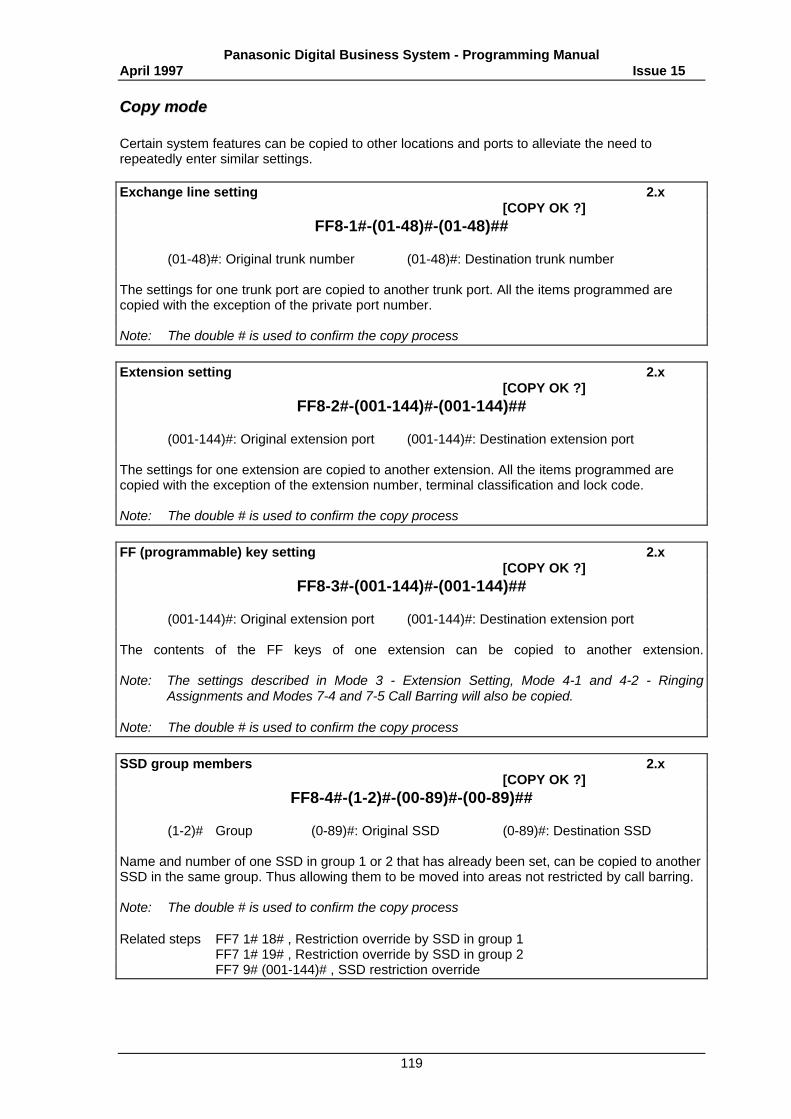
Panasonic Digital Business System - Programming ManualApril 1997 Issue 15
119
CCooppyy mmooddee
Certain system features can be copied to other locations and ports to alleviate the need torepeatedly enter similar settings.
Exchange line setting 2.x[COPY OK ?]
FF8-1#-(01-48)#-(01-48)##
(01-48)#: Original trunk number (01-48)#: Destination trunk number
The settings for one trunk port are copied to another trunk port. All the items programmed arecopied with the exception of the private port number.
Note: The double # is used to confirm the copy process
Extension setting 2.x[COPY OK ?]
FF8-2#-(001-144)#-(001-144)##
(001-144)#: Original extension port (001-144)#: Destination extension port
The settings for one extension are copied to another extension. All the items programmed arecopied with the exception of the extension number, terminal classification and lock code.
Note: The double # is used to confirm the copy process
FF (programmable) key setting 2.x[COPY OK ?]
FF8-3#-(001-144)#-(001-144)##
(001-144)#: Original extension port (001-144)#: Destination extension port
The contents of the FF keys of one extension can be copied to another extension.
Note: The settings described in Mode 3 - Extension Setting, Mode 4-1 and 4-2 - RingingAssignments and Modes 7-4 and 7-5 Call Barring will also be copied.
Note: The double # is used to confirm the copy process
SSD group members 2.x[COPY OK ?]
FF8-4#-(1-2)#-(00-89)#-(00-89)##
(1-2)# Group (0-89)#: Original SSD (0-89)#: Destination SSD
Name and number of one SSD in group 1 or 2 that has already been set, can be copied to anotherSSD in the same group. Thus allowing them to be moved into areas not restricted by call barring.
Note: The double # is used to confirm the copy process
Related steps FF7 1# 18# , Restriction override by SSD in group 1FF7 1# 19# , Restriction override by SSD in group 2FF7 9# (001-144)# , SSD restriction override
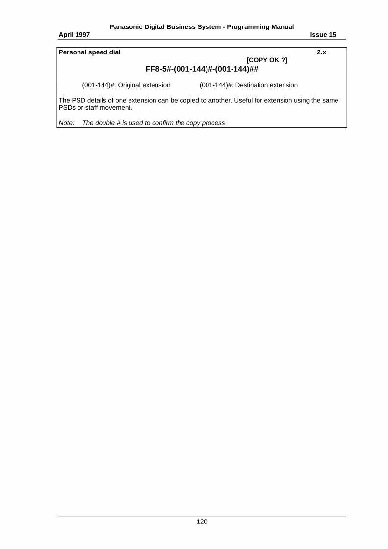
Panasonic Digital Business System - Programming ManualApril 1997 Issue 15
120
Personal speed dial 2.x[COPY OK ?]
FF8-5#-(001-144)#-(001-144)##
(001-144)#: Original extension (001-144)#: Destination extension
The PSD details of one extension can be copied to another. Useful for extension using the samePSDs or staff movement.
Note: The double # is used to confirm the copy process
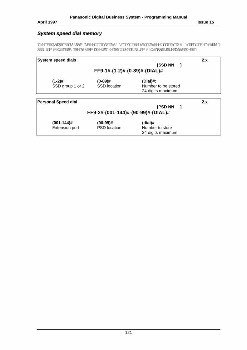
Panasonic Digital Business System - Programming ManualApril 1997 Issue 15
121
SSyysstteemm ssppeeeedd ddiiaall mmeemmoorryy
System speed dials 2.x[SSD NN ]
FF9-1#-(1-2)#-(0-89)#-(DIAL)#
(1-2)# (0-89)# (Dial)#:SSD group 1 or 2 SSD location Number to be stored
24 digits maximum
Personal Speed dial 2.x[PSD NN ]
FF9-2#-(001-144)#-(90-99)#-(DIAL)#
(001-144)# (90-99)# (dial)#Extension port PSD location Number to store
24 digits maximum
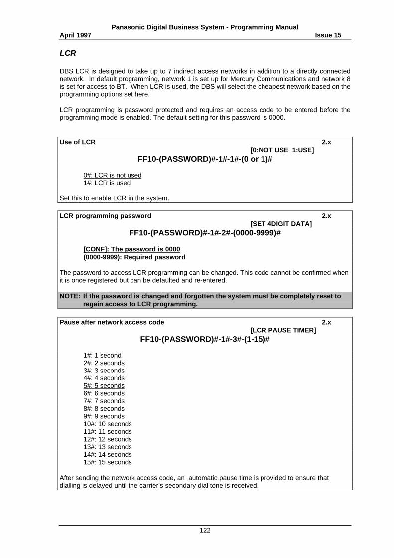
Panasonic Digital Business System - Programming ManualApril 1997 Issue 15
122
LLCCRR
DBS LCR is designed to take up to 7 indirect access networks in addition to a directly connectednetwork. In default programming, network 1 is set up for Mercury Communications and network 8is set for access to BT. When LCR is used, the DBS will select the cheapest network based on theprogramming options set here.
LCR programming is password protected and requires an access code to be entered before theprogramming mode is enabled. The default setting for this password is 0000.
Use of LCR 2.x[0:NOT USE 1:USE]
FF10-(PASSWORD)#-1#-1#-(0 or 1)#
0#: LCR is not used1#: LCR is used
Set this to enable LCR in the system.
LCR programming password 2.x[SET 4DIGIT DATA]
FF10-(PASSWORD)#-1#-2#-(0000-9999)#
[CONF]: The password is 0000(0000-9999): Required password
The password to access LCR programming can be changed. This code cannot be confirmed whenit is once registered but can be defaulted and re-entered.
NOTE: If the password is changed and forgotten the system must be completely reset toregain access to LCR programming.
Pause after network access code 2.x[LCR PAUSE TIMER]
FF10-(PASSWORD)#-1#-3#-(1-15)#
1#: 1 second2#: 2 seconds3#: 3 seconds4#: 4 seconds5#: 5 seconds6#: 6 seconds7#: 7 seconds8#: 8 seconds9#: 9 seconds10#: 10 seconds11#: 11 seconds12#: 12 seconds13#: 13 seconds14#: 14 seconds15#: 15 seconds
After sending the network access code, an automatic pause time is provided to ensure thatdialling is delayed until the carrier’s secondary dial tone is received.
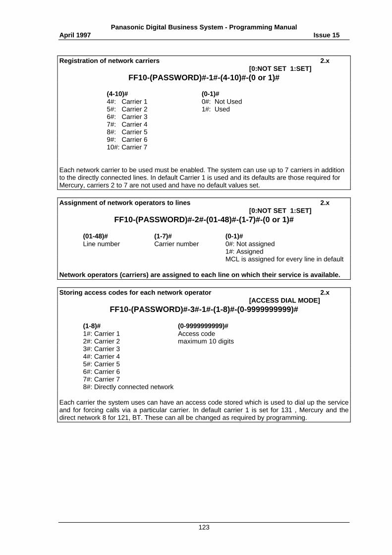
Panasonic Digital Business System - Programming ManualApril 1997 Issue 15
123
Registration of network carriers 2.x[0:NOT SET 1:SET]
FF10-(PASSWORD)#-1#-(4-10)#-(0 or 1)#
(4-10)# (0-1)#4#: Carrier 1 0#: Not Used5#: Carrier 2 1#: Used6#: Carrier 37#: Carrier 48#: Carrier 59#: Carrier 610#: Carrier 7
Each network carrier to be used must be enabled. The system can use up to 7 carriers in additionto the directly connected lines. In default Carrier 1 is used and its defaults are those required forMercury, carriers 2 to 7 are not used and have no default values set.
Assignment of network operators to lines 2.x[0:NOT SET 1:SET]
FF10-(PASSWORD)#-2#-(01-48)#-(1-7)#-(0 or 1)#
(01-48)# (1-7)# (0-1)#Line number Carrier number 0#: Not assigned
1#: AssignedMCL is assigned for every line in default
Network operators (carriers) are assigned to each line on which their service is available.
Storing access codes for each network operator 2.x[ACCESS DIAL MODE]
FF10-(PASSWORD)#-3#-1#-(1-8)#-(0-9999999999)#
(1-8)# (0-9999999999)#1#: Carrier 1 Access code2#: Carrier 2 maximum 10 digits3#: Carrier 34#: Carrier 45#: Carrier 56#: Carrier 67#: Carrier 78#: Directly connected network
Each carrier the system uses can have an access code stored which is used to dial up the serviceand for forcing calls via a particular carrier. In default carrier 1 is set for 131 , Mercury and thedirect network 8 for 121, BT. These can all be changed as required by programming.
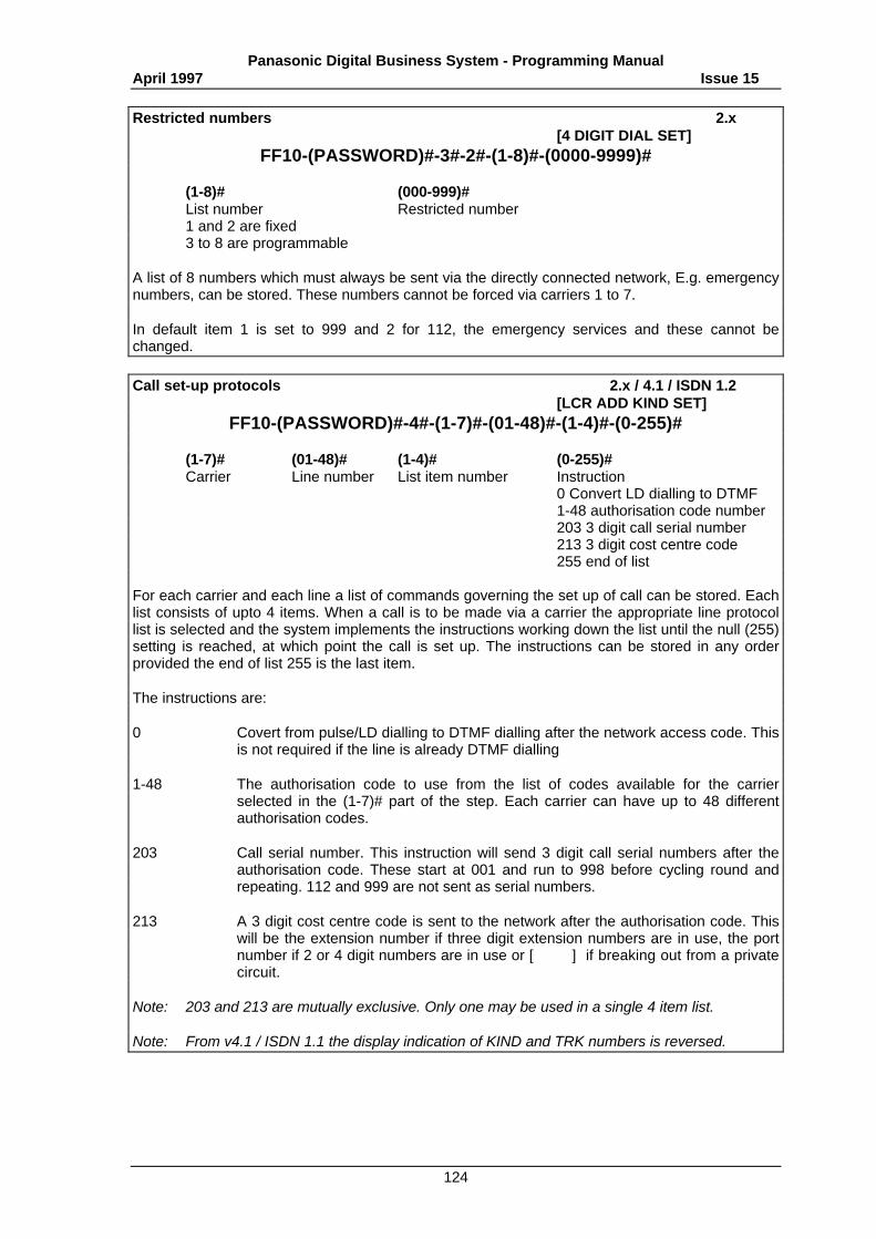
Panasonic Digital Business System - Programming ManualApril 1997 Issue 15
124
Restricted numbers 2.x[4 DIGIT DIAL SET]
FF10-(PASSWORD)#-3#-2#-(1-8)#-(0000-9999)#
(1-8)# (000-999)#List number Restricted number1 and 2 are fixed3 to 8 are programmable
A list of 8 numbers which must always be sent via the directly connected network, E.g. emergencynumbers, can be stored. These numbers cannot be forced via carriers 1 to 7.
In default item 1 is set to 999 and 2 for 112, the emergency services and these cannot bechanged.
Call set-up protocols 2.x / 4.1 / ISDN 1.2[LCR ADD KIND SET]
FF10-(PASSWORD)#-4#-(1-7)#-(01-48)#-(1-4)#-(0-255)#
(1-7)# (01-48)# (1-4)# (0-255)#Carrier Line number List item number Instruction
0 Convert LD dialling to DTMF1-48 authorisation code number203 3 digit call serial number213 3 digit cost centre code255 end of list
For each carrier and each line a list of commands governing the set up of call can be stored. Eachlist consists of upto 4 items. When a call is to be made via a carrier the appropriate line protocollist is selected and the system implements the instructions working down the list until the null (255)setting is reached, at which point the call is set up. The instructions can be stored in any orderprovided the end of list 255 is the last item.
The instructions are:
0 Covert from pulse/LD dialling to DTMF dialling after the network access code. Thisis not required if the line is already DTMF dialling
1-48 The authorisation code to use from the list of codes available for the carrierselected in the (1-7)# part of the step. Each carrier can have up to 48 differentauthorisation codes.
203 Call serial number. This instruction will send 3 digit call serial numbers after theauthorisation code. These start at 001 and run to 998 before cycling round andrepeating. 112 and 999 are not sent as serial numbers.
213 A 3 digit cost centre code is sent to the network after the authorisation code. Thiswill be the extension number if three digit extension numbers are in use, the portnumber if 2 or 4 digit numbers are in use or [ ] if breaking out from a privatecircuit.
Note: 203 and 213 are mutually exclusive. Only one may be used in a single 4 item list.
Note: From v4.1 / ISDN 1.1 the display indication of KIND and TRK numbers is reversed.
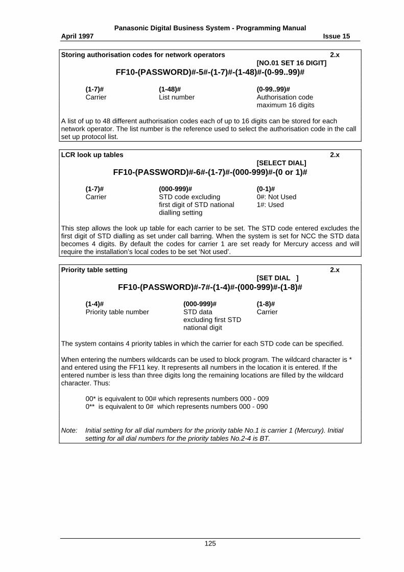
Panasonic Digital Business System - Programming ManualApril 1997 Issue 15
125
Storing authorisation codes for network operators 2.x[NO.01 SET 16 DIGIT]
FF10-(PASSWORD)#-5#-(1-7)#-(1-48)#-(0-99..99)#
(1-7)# (1-48)# (0-99..99)#Carrier List number Authorisation code
maximum 16 digits
A list of up to 48 different authorisation codes each of up to 16 digits can be stored for eachnetwork operator. The list number is the reference used to select the authorisation code in the callset up protocol list.
LCR look up tables 2.x[SELECT DIAL]
FF10-(PASSWORD)#-6#-(1-7)#-(000-999)#-(0 or 1)#
(1-7)# (000-999)# (0-1)#Carrier STD code excluding 0#: Not Used
first digit of STD national 1#: Useddialling setting
This step allows the look up table for each carrier to be set. The STD code entered excludes thefirst digit of STD dialling as set under call barring. When the system is set for NCC the STD databecomes 4 digits. By default the codes for carrier 1 are set ready for Mercury access and willrequire the installation’s local codes to be set ‘Not used’.
Priority table setting 2.x[SET DIAL ]
FF10-(PASSWORD)#-7#-(1-4)#-(000-999)#-(1-8)#
(1-4)# (000-999)# (1-8)#Priority table number STD data Carrier
excluding first STDnational digit
The system contains 4 priority tables in which the carrier for each STD code can be specified.
When entering the numbers wildcards can be used to block program. The wildcard character is *and entered using the FF11 key. It represents all numbers in the location it is entered. If theentered number is less than three digits long the remaining locations are filled by the wildcardcharacter. Thus:
00* is equivalent to 00# which represents numbers 000 - 0090** is equivalent to 0# which represents numbers 000 - 090
Note: Initial setting for all dial numbers for the priority table No.1 is carrier 1 (Mercury). Initialsetting for all dial numbers for the priority tables No.2-4 is BT.
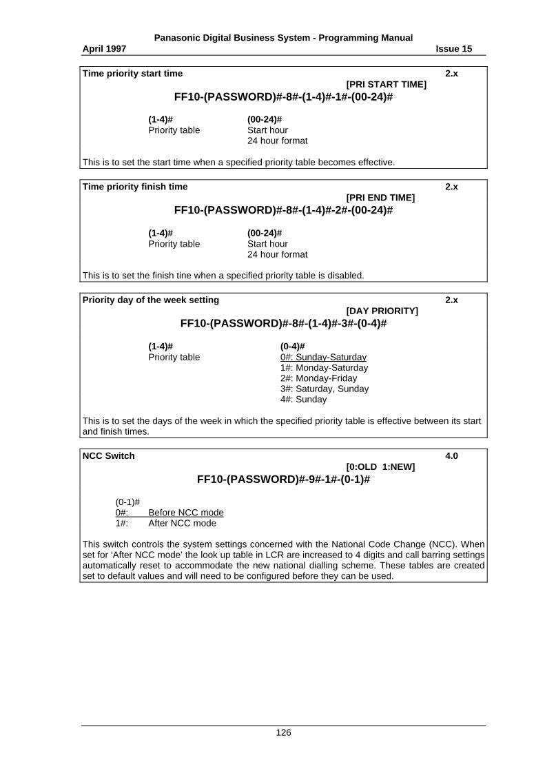
Panasonic Digital Business System - Programming ManualApril 1997 Issue 15
126
Time priority start time 2.x[PRI START TIME]
FF10-(PASSWORD)#-8#-(1-4)#-1#-(00-24)#
(1-4)# (00-24)# Priority table Start hour
24 hour format
This is to set the start time when a specified priority table becomes effective.
Time priority finish time 2.x[PRI END TIME]
FF10-(PASSWORD)#-8#-(1-4)#-2#-(00-24)#
(1-4)# (00-24)#Priority table Start hour
24 hour format
This is to set the finish tine when a specified priority table is disabled.
Priority day of the week setting 2.x[DAY PRIORITY]
FF10-(PASSWORD)#-8#-(1-4)#-3#-(0-4)#
(1-4)# (0-4)#Priority table 0#: Sunday-Saturday
1#: Monday-Saturday2#: Monday-Friday3#: Saturday, Sunday4#: Sunday
This is to set the days of the week in which the specified priority table is effective between its startand finish times.
NCC Switch 4.0[0:OLD 1:NEW]
FF10-(PASSWORD)#-9#-1#-(0-1)#
(0-1)#0#: Before NCC mode1#: After NCC mode
This switch controls the system settings concerned with the National Code Change (NCC). Whenset for ‘After NCC mode’ the look up table in LCR are increased to 4 digits and call barring settingsautomatically reset to accommodate the new national dialling scheme. These tables are createdset to default values and will need to be configured before they can be used.
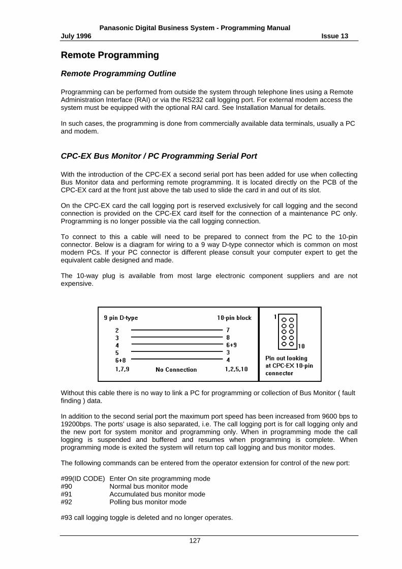
Panasonic Digital Business System - Programming ManualJuly 1996 Issue 13
127
RReemmoottee PPrrooggrraammmmiinngg
Remote Programming Outline
Programming can be performed from outside the system through telephone lines using a RemoteAdministration Interface (RAI) or via the RS232 call logging port. For external modem access thesystem must be equipped with the optional RAI card. See Installation Manual for details.
In such cases, the programming is done from commercially available data terminals, usually a PCand modem.
CPC-EX Bus Monitor / PC Programming Serial Port
With the introduction of the CPC-EX a second serial port has been added for use when collectingBus Monitor data and performing remote programming. It is located directly on the PCB of theCPC-EX card at the front just above the tab used to slide the card in and out of its slot.
On the CPC-EX card the call logging port is reserved exclusively for call logging and the secondconnection is provided on the CPC-EX card itself for the connection of a maintenance PC only.Programming is no longer possible via the call logging connection.
To connect to this a cable will need to be prepared to connect from the PC to the 10-pinconnector. Below is a diagram for wiring to a 9 way D-type connector which is common on mostmodern PCs. If your PC connector is different please consult your computer expert to get theequivalent cable designed and made.
The 10-way plug is available from most large electronic component suppliers and are notexpensive.
Without this cable there is no way to link a PC for programming or collection of Bus Monitor ( faultfinding ) data.
In addition to the second serial port the maximum port speed has been increased from 9600 bps to19200bps. The ports’ usage is also separated, i.e. The call logging port is for call logging only andthe new port for system monitor and programming only. When in programming mode the calllogging is suspended and buffered and resumes when programming is complete. Whenprogramming mode is exited the system will return top call logging and bus monitor modes.
The following commands can be entered from the operator extension for control of the new port:
#99(ID CODE) Enter On site programming mode#90 Normal bus monitor mode#91 Accumulated bus monitor mode#92 Polling bus monitor mode
#93 call logging toggle is deleted and no longer operates.
Panasonic Digital Business System - Programming ManualApril 1997 Issue 15
128
Additional programming steps have been added to the call logging parameters to allowconfiguration of the new port.
Starting Remote Programming
There are two ways of starting remote programming.
The first method is completely externally using the DISA function and dialling directly to the RAIcard.
The second method is to put the system in hold with the operator's telephone and have theoperator initiate the link to the RAI card.
A) Remote Programming Mode with DISA
After the system has answered the call made to the exchange line specified in the system asDISA, enter the DISA ID if used and then dial #6 and the remote programming ID. The remoteprogramming ID is 9999 in default. The system will respond with the opening screen for remoteaccess.
B) Remote Programming Mode by Attendant's telephone
The incoming call for remote programming is placed on hold by the operator’s extension and theoperator dials #6 and the programming ID (9999 default), this will connect to the RAI card anddisplay the opening screen.
Remote Programming Modes
There are 3 modes for the remote programming. When the opening screen is displayed thesemodes can be selected.
INPUT [P] for ProgrammingINPUT [D] for Memory Dump (Hex dump - for engineering use)INPUT [CTRL] [Z] Remote Maintenance Complete - Quit
Panasonic Digital Business System - Programming ManualApril 1997 Issue 15
129
Effective Number of Digits for Input
When the number of digits input is less than 3, 0 is used to fill out the entry to make it 3 digitsWhen it is more than 3 digits, the last 3 digits only are taken while the rest are ignored.
1 => 001100 => 1001000 => 00012345 => 345
This restriction is common to all the remote programming modes.
Completion of Remote Programming
The remote programming operation is completed by entering [Ctrl] + [Z]. The first time will returnto the top level screen ( or disconnect if already at the top level screen) and the second time willsign off.
The following situations will also cause the remote programming mode to terminate.
A) When data has not been input for more than 16 minutes.
B) When the outside line is cut off.
Remote Programming Display - Sample
REMT>
Press "P" and Enter key.(Note : "P" must be input by Capital letter)
*DBS System Programming*
- 0.1 System param - 0.6 Name assignment- 0.2 Trunk param - 0.7 TRS param- 0.3 Extension param - 0.8 Copy mode- 0.4 Ring assignment - 0.9 SPD param- 0.5 FF key assignment -.1.0 LCD param
* Control key*
- B : Back to previous address- F : Forward to next address- R : Return to provide mode- b : Back to previous port- f: Forward to previous port
Enter Selection Data
Press "- 0.1" and press "ENTER key"
SYSTEM PROGRAM*System Program Parameters*
1. Calendar 5. ID code set for Program2. System mode sel 6. F.N.P. Setting3. Time 7. F.N.P. reference4. Remote mente 8. DISA ID code setting
Panasonic Digital Business System - Programming ManualApril 1997 Issue 15
130
Press "1" and press "ENTER key"
SELECT TIME MODECalendar
1. Month, Day , Year2. Hour Minute
Enter Selection Data
Press "1" and press "Enter key"
DATA SET MODE*Day Month Year Setting Mode*
Input Data Format : DDMMYYDD Day (01-31)MM Month (01-12)YY Year ('89 - '20)
Enter Selection Data
Press "1" and press "Enter key"
TIME SET MODE*Hour Minutes Setting Mode*
Input Data Format : HHMM
HH Hour (00-23)MM Minute (00-59)
Enter Selection Data
Press "0821" and press "Enter key"

![Digital Laser Sensor [Amplifier-separated] LS · PDF filepanasonic-electric-works.net/sunx ... Selection Guide Amplifier Built-in Amplifier-separated LS Digital fiber sensor FX-500/300](https://img.pdfslide.us/doc/110x75/5aacad2b7f8b9a8f498d55e8/digital-laser-sensor-amplifier-separated-ls-selection-guide-amplifier-built-in.jpg)