Embed Size (px)
Citation preview
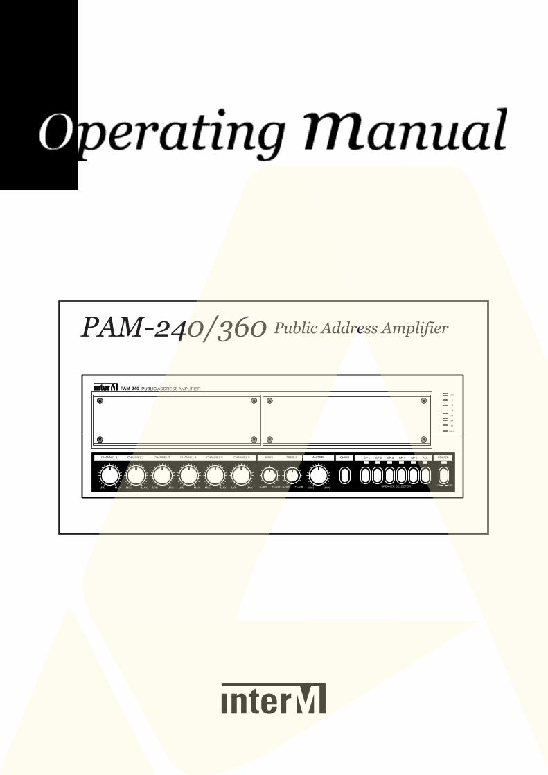
PAM-240/360 Public Address Amplifier
PUBLIC ADDRESS AMPLIFIER PAM-240
PROT
-8
-11
-14
-19
-6
0
CLIP
SP 1 SP 2 SP 3 SP 4 SP 5 ALLCHANNEL 6CHANNEL 5CHANNEL 4CHANNEL 3CHANNEL 2CHANNEL 1 POWERBASS TREBLE CHIME
MIN MAX -12dB +12dB -12dB +12dB
MASTER
MIN MAXMIN MAXMIN MAXMIN MAXMIN MAXMIN MAX SPEAKER SELECTOR ON OFF
ContentsContents1. Unpacking and Installation.....................................................................................................1
2. Features ................................................................................................................................2
3. Front Panel Controls...............................................................................................................3
4. Rear Panel Controls ...............................................................................................................4
5. Installation of The Speaker .....................................................................................................7
6. Applications ..........................................................................................................................8
7. Block Diagram.......................................................................................................................9
8. Specifications.......................................................................................................................10
OFFICE :653-5 BANGHAK-DONG, DOBONG-KU, SEOUL, KOREATEL : 82-2-2289-8140~8, FAX : 82-2-2289-8144
Home Page : http://www.inter-m.comE-mail : [email protected]
Unpacking and InstallationUnpacking and Installation
Although it is neither complicated to install nor difficult to operate your Public Address Amplifier, a few min-utes of your time is required to read this manual for a properly wired installation and becoming familiarwith its many features and how to use them. Please take a great care in unpacking your set and do not dis-card the carton and other packing materials. They may be needed when moving your set and are requiredif it ever becomes necessary to return your set for service. Never place the unit near radiator, in front of heating vents, to direct sun light, in excessive humid or dustylocation to avoid early damage and for yours of quality use. Connect your complementary components asillustrated in the following page.
PAM-240/360 1
PUBLIC ADDRESS AMPLIFIER
RISK OF ELECTRIC SHOCKDO NOT OPEN
CAUTION
CAUTION: TO REDUCE THE RISK OF ELECTRIC SHOCK.
DO NOT REMOVE COVER (OR BACK).
NO USER-SERVICEABLE PARTS INSIDE.
REFER SERVICING TO QUALIFIED SERVICE PERSONNEL.
WARNING
To prevent fire or shock hazard, do notexpose the unit to rain or moisture.
This symbol is intended to alert the user to thepresence of uninsulated “dangerous voltage”within the product’s enclosure that may be of suf-ficient magnitude to constitute a risk of electricshock to persons.
This symbol is intended to alert the user to thepresence of important operation and mainte-nance (servicing) instructions in the literatureaccompanying the appliance.
Caution: To prevent electric shock do not use this (polarized) plugwith an extension cord, receptacle or other outlet unlessthe blades can be fully inserted to prevent blade expo-sure.
Attentions: Pour prévenir les chocs électriques ne pas utiliser cettefiche polarisée avec un prolongateur, une prise decourant on une autre sortie de courant, sauf si leslames peuvent étre insérées à fond sans en laisseraucune partie à découvert.
FeaturesFeatures- MODULAR AMPLIFIER
This AMP is perfect for applications requiring High Reliability, Excellent Audio Quality.Units assemble in any configuration, AMP+Tuner, AMP+CD (Deck), AMP+Tuner+CD (Deck), utilizing mod-ules.
- INPUT GAIN CONTROLSThis system controls input gain in rear panel input gain volume per CH, you can use conveniently.
- SPEAKER SELECT6 speaker selector switches are provided to enable you to select 5 speakers individually or totally.
- CHIME WITH FOUR TONESYou can conveniently use four tone chime before the announcement.
- MUTING FOR PRIORITYCH1, 2, CHIME and TELEPHONE have priority to the others signal.
- TELEPHONE INPUT/MUSIC-ON HOLDTo connect with the telephone system, the function of TELEPHONE INPUT and MUSIC-ON HOLD are provid-ed (MUSIC-ON HOLD is only for PAM-Tuner).
- REMOTE CONTROL SYSTEMSpeaker zone can be selected and chime operated by remote amplifier.
PAM-240/3602
PUBLIC ADDRESS AMPLIFIER
Front Panel ControlsFront Panel Controls
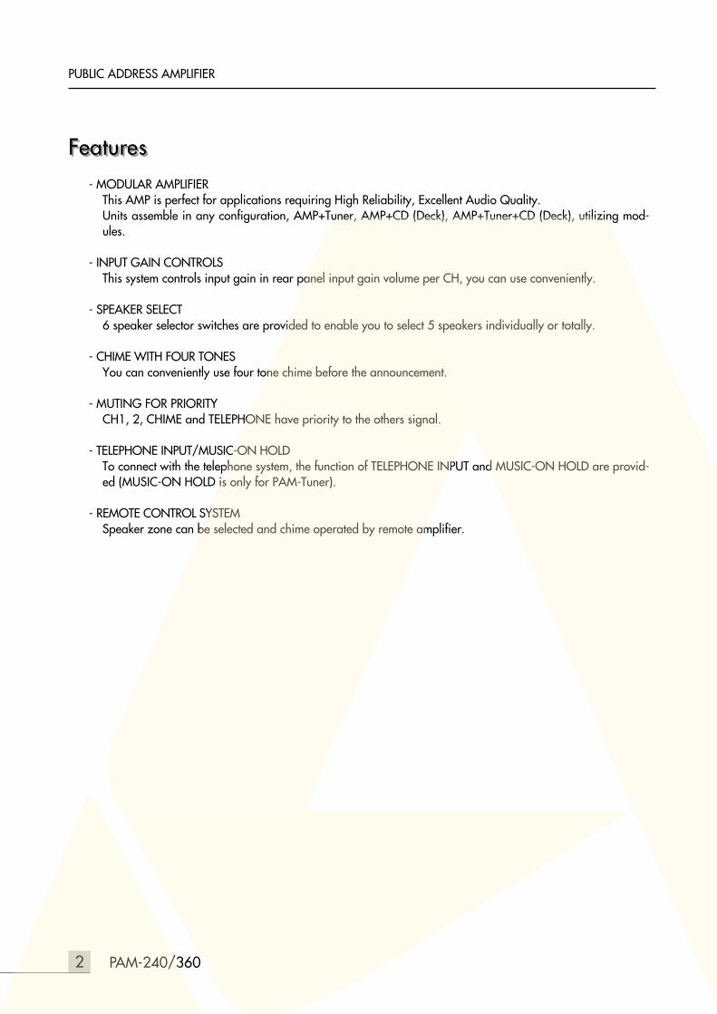
1. DECK, CD PLAYER OR TUNER OPTIONThis Panel is used to connecting the DECK, CD player or TUNER.*Connection of option is provided the connector of internal unit.
2. PROTECTION INDICATORThis LED indicates the condition of the protection circuit. When the protection LED is “ON” the amplifier is notoperating normally (overheating and limiting), please check the INPUT/OUTPUT condition of the amplifier.
3. OUTPUT LEVEL DISPLAYThis display indicates the output level (RMS).
4. POWER SWITCHPressing this switch to ON will make the power indicating LED ON and supply the power to this unit.
5. SPEAKER SELECTORThese switches are used for connecting the output of amplifier to the speakers individually or totally.
6. CHIME BUTTONPressing this button will activate 4 tone chime circuitry.
7. MASTER VOLUMEThis control is used for adjusting the volume of finally mixed sound.
8. TONE CONTROLEach frequency level is adjusted to ±12dB by the 2 controls from 100Hz to 10kHz.
9. CH1~CH6 VOLUMEThese volume adjust the level of CH1~CH6.
PAM-240/360 3
PUBLIC ADDRESS AMPLIFIER
PUBLIC ADDRESS AMPLIFIER PAM-240
PROT
-8
-11
-14
-19
-6
0
CLIP
SP 1 SP 2 SP 3 SP 4 SP 5 ALLCHANNEL 6CHANNEL 5CHANNEL 4CHANNEL 3CHANNEL 2CHANNEL 1 POWERBASS TREBLE CHIME
MIN MAX -12dB +12dB -12dB +12dB
MASTER
MIN MAXMIN MAXMIN MAXMIN MAXMIN MAXMIN MAX SPEAKER SELECTOR ON OFF
7
31
5 49
2
68
Rear Panel ControlsRear Panel Controls
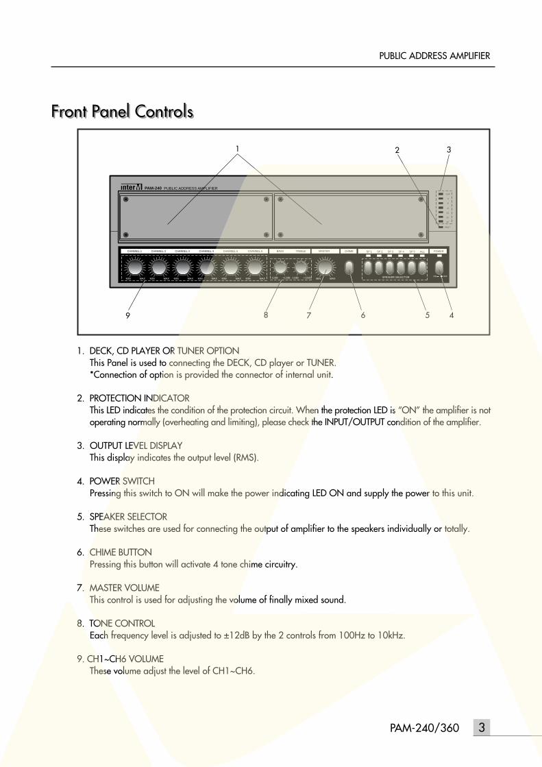
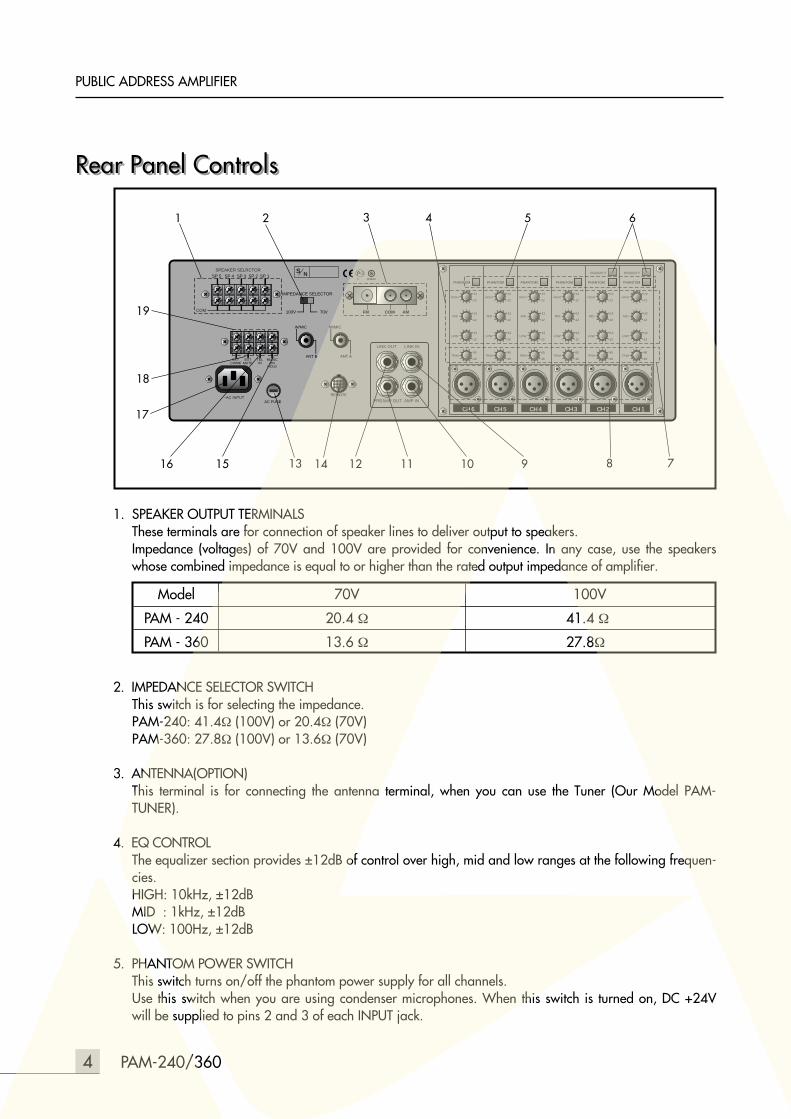
1. SPEAKER OUTPUT TERMINALSThese terminals are for connection of speaker lines to deliver output to speakers.Impedance (voltages) of 70V and 100V are provided for convenience. In any case, use the speakerswhose combined impedance is equal to or higher than the rated output impedance of amplifier.
2. IMPEDANCE SELECTOR SWITCHThis switch is for selecting the impedance.PAM-240: 41.4Ω (100V) or 20.4Ω (70V)PAM-360: 27.8Ω (100V) or 13.6Ω (70V)
3. ANTENNA(OPTION)This terminal is for connecting the antenna terminal, when you can use the Tuner (Our Model PAM-TUNER).
4. EQ CONTROLThe equalizer section provides ±12dB of control over high, mid and low ranges at the following frequen-cies.HIGH: 10kHz, ±12dBMID : 1kHz, ±12dBLOW: 100Hz, ±12dB
5. PHANTOM POWER SWITCHThis switch turns on/off the phantom power supply for all channels.Use this switch when you are using condenser microphones. When this switch is turned on, DC +24Vwill be supplied to pins 2 and 3 of each INPUT jack.
PAM-240/3604
PUBLIC ADDRESS AMPLIFIER
CH 1
PHANTOM
PRIORITY
CH 2
PHANTOM
PRIORITY
CH 3
PHANTOM
CH 4
PHANTOM
CH 5
PHANTOM
CH 6
PHANTOM
LINK OUT LINK IN
PREAMP OUT AMP IN~AC INPUT
SPEAKER SELRCTORSP 4SP 5 SP 3 SP 2 SP 1
EXTMUTE
TELIN
MUSICON
HOLD
EXTCHIME
AC FUSE
IMPEDANCE SELECTOR
100V 70V
S N
W/MIC
ANT B
W/MIC
ANT A
4
COM
TRIM
LOW
MID
HIGH+12
-12
+12
-12
+12
-12
-60
-16TRIM
LOW
MID
HIGH+12
-12
+12
-12
+12
-12
-60
-16TRIM
LOW
MID
HIGH+12
-12
+12
-12
+12
-12
-60
-16TRIM
LOW
MID
HIGH+12
-12
+12
-12
+12
-12
-60
-16TRIM
LOW
MID
HIGH+12
-12
+12
-12
+12
-12
-60
-16TRIM
LOW
MID
HIGH+12
-12
+12
-12
+12
-12
-60
-16
FM COM AM
1
12141516
17
19
13 10 8 79
652 3
11
18REMOTE
Model 70V 100V
PAM - 240 20.4 Ω 41.4 Ω
PAM - 360 13.6 Ω 27.8Ω
If you do not need phantom power, be sure to leave this turned off.* It is safe to connect balanced dynamic microphones or line level devices even if this switch is left on,but connecting unbalanced devices or devices whose transformers are center-grounded will cause humor malfunctions.
6. PRIORITY SWITCHThis switch have priority to the others channels.
7. INPUT GAIN CONTROLAccording to the input signal source, adjust adequately these gain controls not to exceed input sensitivi-ty. When the input level exceed the rated sensitivity, output signal of amplifier could be distorted andoverloaded. Gain adjusting range of these volumes are 44dB, and general position of the volume is asfollowing.MIC (Microphone) ..........................................................................-50 ~ -60dBMIC ATT (Electric Guitar).................................................................-30 ~ -50dBAUX (Deck, Tuner, etc.) ...................................................................-20 ~ -30dB
8. CH1~CH6 INPUT JACKThese are input terminals which is designed electrical balanced circuitry. Optionally, transformer bal-anced circuitry is optional per buyer’s order.
9. LINK IN JACKTo the expansion of input channels, this jack is provided to connect with the output terminal of externalmixer.
10. AMP IN JACKThis jack is for connecting the external signal input. If plug is inserted on this jack, mixed signal of allinput is not connected to main amplifier, and only amp in signal is connected.
11. PRE AMP OUT JACKThis jack is for connecting the preamp out signal to external effect derive or external musical instrument.If the plug is inserted on this jack mixed signal of all input is not connect to main amplifier and only ampin signal is connected.
12. LINK OUT JACKThis jack is used to connecting the same kinds amp of this unit and record in of deck.
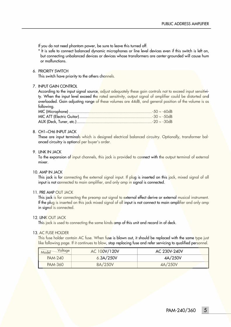
13. AC FUSE HOLDERThis fuse holder contain AC fuse. When fuse is blown out, it should be replaced with the same type justlike following page. If it continues to blow, stop replacing fuse and refer servicing to qualified personnel.
PAM-240/360 5
PUBLIC ADDRESS AMPLIFIER
Model Voltage AC 100V/120V AC 230V-240V
PAM-240 6.3A/250V 4A/250V
PAM-360 8A/250V 4A/250V
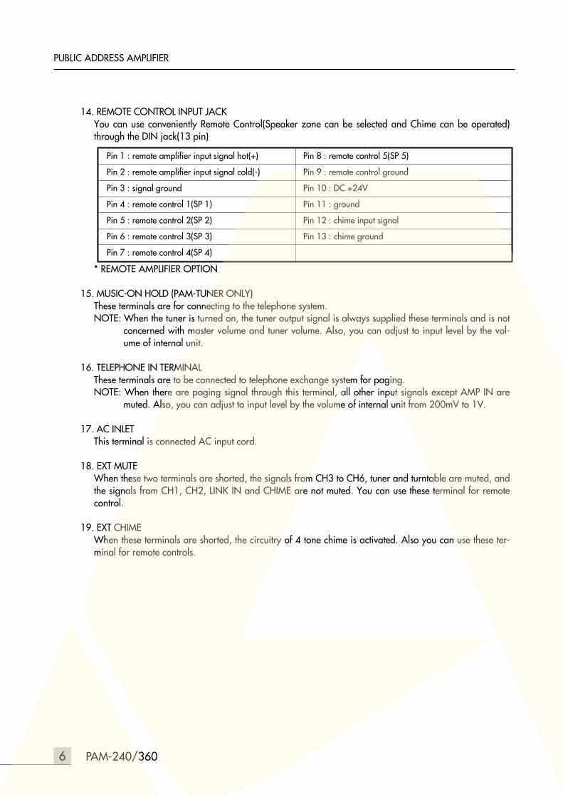
14. REMOTE CONTROL INPUT JACKYou can use conveniently Remote Control(Speaker zone can be selected and Chime can be operated)through the DIN jack(13 pin)
* REMOTE AMPLIFIER OPTION
15. MUSIC-ON HOLD (PAM-TUNER ONLY)These terminals are for connecting to the telephone system.NOTE: When the tuner is turned on, the tuner output signal is always supplied these terminals and is not
concerned with master volume and tuner volume. Also, you can adjust to input level by the vol-ume of internal unit.
16. TELEPHONE IN TERMINALThese terminals are to be connected to telephone exchange system for paging.NOTE: When there are paging signal through this terminal, all other input signals except AMP IN are
muted. Also, you can adjust to input level by the volume of internal unit from 200mV to 1V.
17. AC INLETThis terminal is connected AC input cord.
18. EXT MUTEWhen these two terminals are shorted, the signals from CH3 to CH6, tuner and turntable are muted, andthe signals from CH1, CH2, LINK IN and CHIME are not muted. You can use these terminal for remotecontrol.
19. EXT CHIMEWhen these terminals are shorted, the circuitry of 4 tone chime is activated. Also you can use these ter-minal for remote controls.
6 PAM-240/360
PUBLIC ADDRESS AMPLIFIER
Pin 1 : remote amplifier input signal hot(+) Pin 8 : remote control 5(SP 5)
Pin 2 : remote amplifier input signal cold(-) Pin 9 : remote control ground
Pin 3 : signal ground Pin 10 : DC +24V
Pin 4 : remote control 1(SP 1) Pin 11 : ground
Pin 5 : remote control 2(SP 2) Pin 12 : chime input signal
Pin 6 : remote control 3(SP 3) Pin 13 : chime ground
Pin 7 : remote control 4(SP 4)
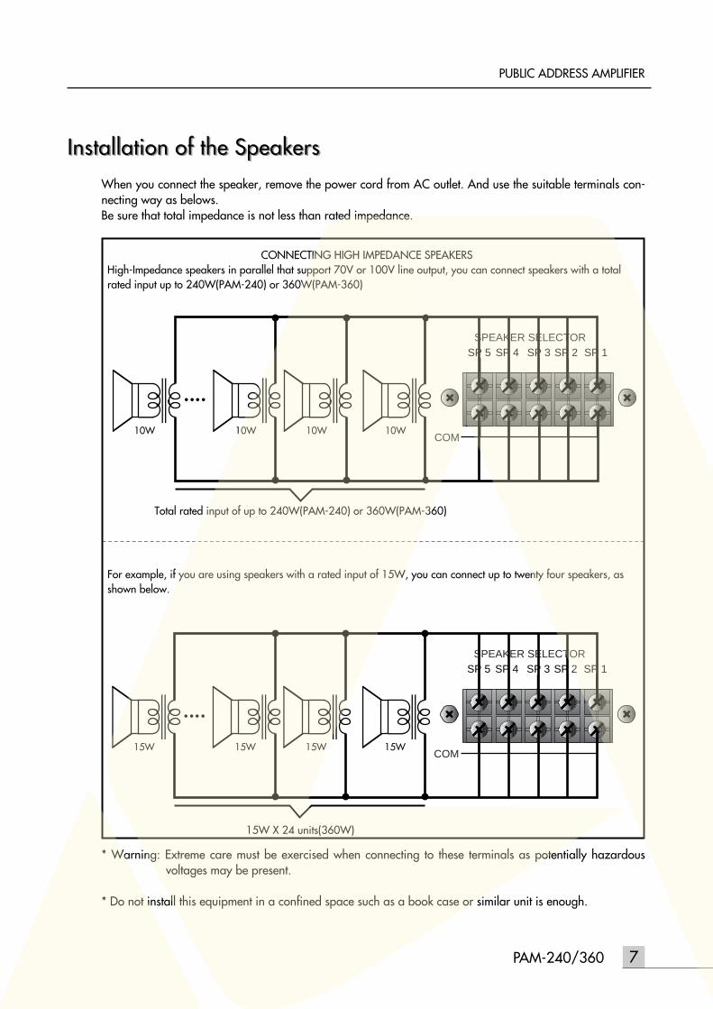
Installation of the SpeakersInstallation of the SpeakersWhen you connect the speaker, remove the power cord from AC outlet. And use the suitable terminals con-necting way as belows.Be sure that total impedance is not less than rated impedance.
* Warning: Extreme care must be exercised when connecting to these terminals as potentially hazardousvoltages may be present.
* Do not install this equipment in a confined space such as a book case or similar unit is enough.
7PAM-240/360
PUBLIC ADDRESS AMPLIFIER
SPEAKER SELECTORSP 5 SP 4 SP 3 SP 2 SP 1
COM10W 10W10W10W
CONNECTING HIGH IMPEDANCE SPEAKERSHigh-Impedance speakers in parallel that support 70V or 100V line output, you can connect speakers with a totalrated input up to 240W(PAM-240) or 360W(PAM-360)
Total rated input of up to 240W(PAM-240) or 360W(PAM-360)
For example, if you are using speakers with a rated input of 15W, you can connect up to twenty four speakers, asshown below.
15W X 24 units(360W)
SPEAKER SELECTORSP 5 SP 4 SP 3 SP 2 SP 1
COM15W 15W15W15W
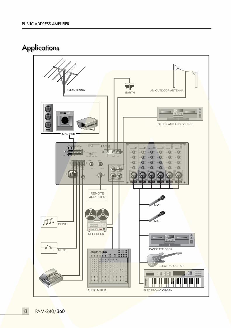
ApplicationsApplications
8 PAM-240/360
PUBLIC ADDRESS AMPLIFIER
CH 1
PHANTOM
PRIORITY
CH 2
PHANTOM
PRIORITY
CH 3
PHANTOM
CH 4
PHANTOM
CH 5
PHANTOM
CH 6
PHANTOM
LINK OUT LINK IN
PREAMP OUT AMP IN~AC INPUT
SPEAKER SELRCTORSP 4SP 5 SP 3 SP 2 SP 1
EXTMUTE
TELIN
MUSICON
HOLD
EXTCHIME
AC FUSE
W/MIC
ANT B
W/MIC
ANT A
IMPEDANCE SELECTOR
100V 70V
S N
COM
TRIM
LOW
MID
HIGH+12
-12
+12
-12
+12
-12
-60
-16TRIM
LOW
MID
HIGH+12
-12
+12
-12
+12
-12
-60
-16TRIM
LOW
MID
HIGH+12
-12
+12
-12
+12
-12
-60
-16TRIM
LOW
MID
HIGH+12
-12
+12
-12
+12
-12
-60
-16TRIM
LOW
MID
HIGH+12
-12
+12
-12
+12
-12
-60
-16TRIM
LOW
MID
HIGH+12
-12
+12
-12
+12
-12
-60
-16
FM COM AM
REMOTE
CH 1
AUDIO MIXER
OTHER AMP AND SOURCE
FM ANTENNA AM OUTDOOR ANTENNA
ELECTRONIC ORGAN
CASSETTE DECK
ELECTRIC GUITAR
EARTH
SPEAKER
CHIME
MUTE
REMOTEAMPLIFIER
MIC
ON
MIC
ON
REEL DECK
9PAM-240/360
PUBLIC ADDRESS AMPLIFIER
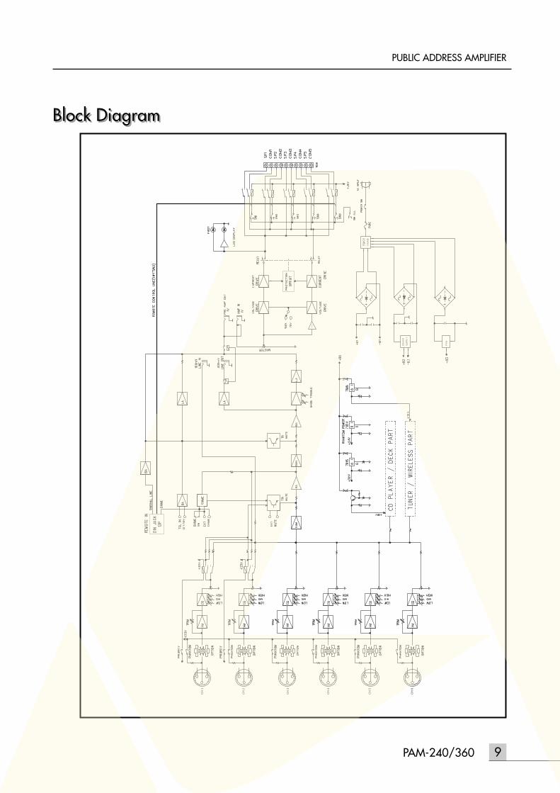
Block DiagramBlock Diagram
CH
1
CH
2
CH
3
CH
4
CH
5
CH
6
Specifications
10 PAM-240/360
PUBLIC ADDRESS AMPLIFIER
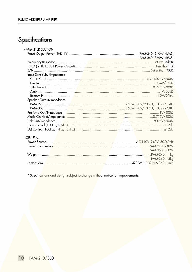
Specifications ..........................................................0dB=0.775Vrms
- AMPLIFIER SECTIONRated Output Power (THD 1%)............................................................................PAM-240: 240W (RMS)........................................................................................................................PAM-360: 360W (RMS)Frequency Response ...........................................................................................................80Hz–20kHzT.H.D (at 1kHz Half Power Output) .......................................................................................Less than 1%S/N .............................................................................................................................Better than 95dBInput Sensitivity/Impedance
CH 1~CH 6......................................................................................................... 1mV~160mV/600ΩLink In.......................................................................................................................... 100mV/15kΩTelephone In.................................................................................................................0.775V/600ΩAmp In ................................................................................................................................1V/20kΩRemote In .........................................................................................................................1.2V/20kΩ
Speaker Output/ImpedancePAM-240........................................................................................240W: 70V/20.4Ω, 100V/41.4ΩPAM-360....................................................................................... 360W: 70V/13.6Ω, 100V/27.8Ω
Pre Amp Out/Impedance ........................................................................................................1V/600ΩMusic On Hold/Impedance ..............................................................................................0.775V/600ΩLink Out/Impedance.........................................................................................................500mV/600ΩTone Control (100Hz, 10kHz) .......................................................................................................±12dBEQ Control (100Hz, 1kHz, 10kHz)................................................................................................±12dB
- GENERALPower Source ................................................................................................AC 110V–240V, 50/60HzPower Consumption .....................................................................................................PAM-240: 240W..................................................................................................................................PAM-360: 300WWeight..........................................................................................................................PAM-240: 11kg....................................................................................................................................PAM-360: 13kgDimensions ...............................................................................................420(W) 132(H) 360(D)mm
* Specifications and design subject to change without notice for improvements.

MADE IN KOREA9007979410