Embed Size (px)
Citation preview
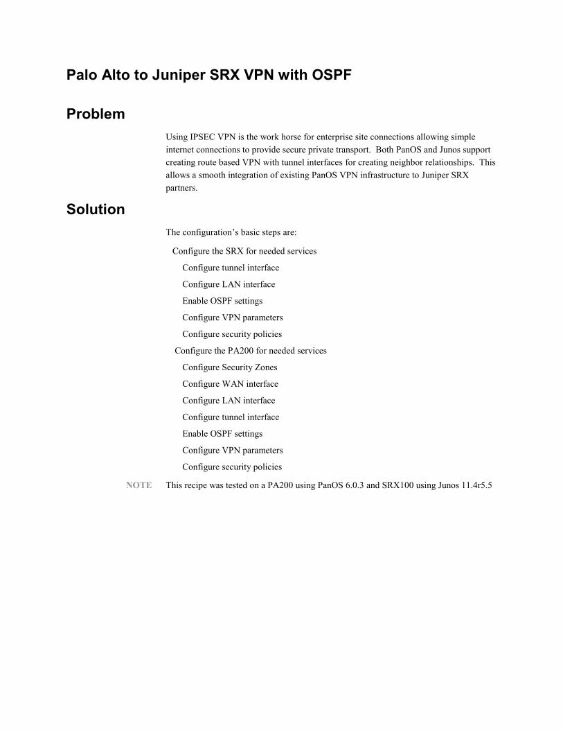
Palo Alto to Juniper SRX VPN with OSPF
Problem
Using IPSEC VPN is the work horse for enterprise site connections allowing simple
internet connections to provide secure private transport. Both PanOS and Junos support
creating route based VPN with tunnel interfaces for creating neighbor relationships. This
allows a smooth integration of existing PanOS VPN infrastructure to Juniper SRX
partners.
Solution
The configuration’s basic steps are:
Configure the SRX for needed services
Configure tunnel interface
Configure LAN interface
Enable OSPF settings
Configure VPN parameters
Configure security policies
Configure the PA200 for needed services
Configure Security Zones
Configure WAN interface
Configure LAN interface
Configure tunnel interface
Enable OSPF settings
Configure VPN parameters
Configure security policies
NOTE This recipe was tested on a PA200 using PanOS 6.0.3 and SRX100 using Junos 11.4r5.5

Steve Puluka 2 of 11
Figure: The Topology of this Recipe’s Configuration
Configure the SRX tunnel interface
Create the VPN tunnel interface and assign an IP range and address:
set interfaces st0 unit 0 family inet address 10.0.0.1/24
set interfaces st0 unit 0 point-to-point
set security zones security-zone trust interfaces st0.0
Configure the SRX LAN interface
Create a LAN interface; place it in the trust zone:
set interfaces fe-0/0/1 unit 0 family ethernet-switching
set interfaces vlan unit 0 family inet address 10.0.1.1/24;
set vlans vlan-trust vlan-id 2
set vlans vlan-trust l3-interface vlan.0
set vlans vlan-trust interface fe-0/0/1.0
set security zones security-zone trust host-inbound-traffic system-
services all
set security zones security-zone trust interfaces vlan.0
Configure the SRX OSPF parameters
Enable OSPF on the SRX and assign the local vlan interface and the tunnel interface to
OSPF area 0:
set protocols ospf area 0 interface vlan.0
set protocols ospf area 0 interface st0.0
Allow the host services for OSPF on the interfaces:
set security zones security-zone trust interfaces vlan.0 host-inbound-
traffic protocols ospf
set security zones security-zone trust interfaces st0.0 host-inbound-
traffic protocols ospf
Configure vlan.0 to announce OSPF routes:
set protocols ospf area 0 interface vlan.0 passive
Configure the OSPF router-id
set routing-options router-id 10.0.1.1
Configure the SRX VPN parameters
Start by configuring the local gateway interface for the VPN. This will be the public IP
address and interface from the local internet service, and placw these into the untrust
zone in the primary routing instance:
Configure the internet static ip address on the gateway interface:
set interfaces fe-0/0/0 unit 0 family inet address 1.1.1.1/24
Now set the default route for the local internet service in the primary routing instance:
set routing-options static route 0.0.0.0/0 next-hop 1.1.1.254
Place the gateway interface into the untrust zone in the primary routing instance:

Steve Puluka 4 of 11
set security zones security-zone untrust interfaces fe-0/0/0.0
Now allow management services on this interface for the VPN IKE connections. You
can also allow management services as needed on this interface, but the IKE services are
required to establish the VPN connection. Since this is an Internet-facing interface, you
will not enable any other system services for now:
set security zones security-zone untrust host-inbound-traffic system-
services ike
Next, configure the remote gateway IKE parameters for policy and a preshared key.
set security ike policy ike-policy1 mode main
set security ike policy ike-policy1 proposal-set standard
set security ike policy ike-policy1 pre-shared-key ascii-text
"sharedsecret"
Now create the IPSEC parameters for the VPN connection.
set security ipsec policy vpn-policy1 proposal-set standard
Follow these steps to create the route-based VPN using the tunnel interface you just
created.
set security ike gateway ike-gate1 ike-policy ike-policy1
set security ike gateway ike-gate1 address 2.2.2.2
set security ike gateway ike-gate1 external-interface fe-0/0/0.0
Then use the existing policy to create the IPSEC Phase 2 connection and tie this to the
tunnel interface:
set security ipsec vpn ike-vpn1 ike gateway ike-gate1
set security ipsec vpn ike-vpn1 ike ipsec-policy vpn-policy1
set security ipsec vpn ike-vpn1 bind-interface st0.0
set security ipsec vpn ike-vpn1 establish-tunnels immediately
Finally, set the VPN MTU to the most common value to prevent fragmentation issues of
traffic across the tunnel:
set security flow tcp-mss ipsec-vpn mss 1350
Configure the SRX Security Policy
Create a security policy to permit traffic across the vpn tunnel. In this case both the
tunnel interface and the local LAN interface are in the same security zone, trust. Thus we
need a trust to trust policy to permit the communication. Here we create an open any
address to any protocol policy. These can be adjusted as desired to more tightly control
traffic.
You can also place the tunnel interface into a separate zone to allow a separate of policies
for communications with the vpn as opposed to the local zone.
set security policies from-zone trust to-zone trust policy allow-all match
source-address any destination-address any application any
set security policies from-zone trust to-zone trust policy allow-all then
permit
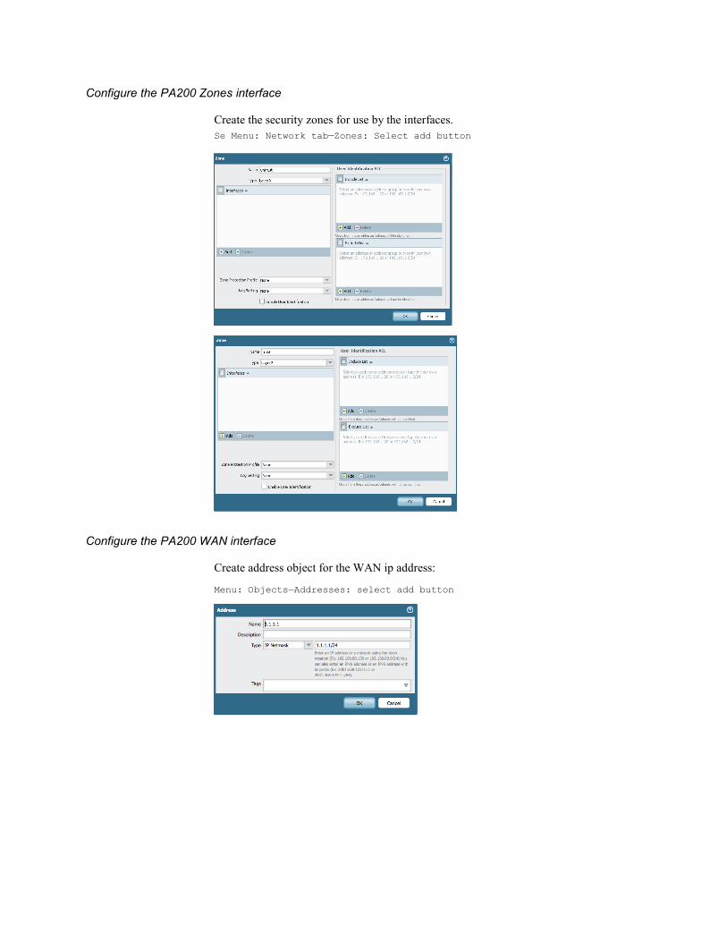
Configure the PA200 Zones interface
Create the security zones for use by the interfaces.
Se Menu: Network tab—Zones: Select add button
Configure the PA200 WAN interface
Create address object for the WAN ip address:
Menu: Objects—Addresses: select add button
Steve Puluka 6 of 11
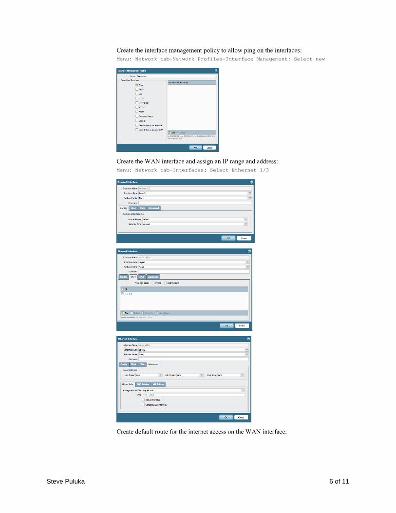
Create the interface management policy to allow ping on the interfaces:
Menu: Network tab—Network Profiles—Interface Management: Select new
Create the WAN interface and assign an IP range and address:
Menu: Network tab—Interfaces: Select Ethernet 1/3
Create default route for the internet access on the WAN interface:

Menu: Networks—virtual routers: select Default and Static Route tab: add
button
Configure the PA200 LAN interface
Create address object for the LAN ip address:
Menu: Objects—Addresses: select add button
Create the LAN interface and assign an IP range and address:
Se Menu: Network tab—Interfaces: Select Ethernet 1/4
Steve Puluka 8 of 11
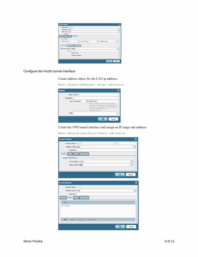
Configure the PA200 tunnel interface
Create address object for the LAN ip address:
Menu: Objects—Addresses: select add button
Create the VPN tunnel interface and assign an IP range and address:
Menu: Network—interfaces—Tunnel: add button

Configure the PA200 OSPF parameters
Configure router to enable OSPF add the router ID and area 0:
Menu: Nework—Virtual Routers: Select default
Enable OSPF and assign the local interface and the tunnel interface to OSPF area 0 on the
interfaces tab. The LAN interface is passive and broadcast.
The tunnel interface is point-to-point:
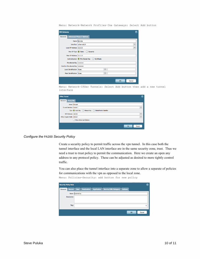
Configure the PA200 VPN parameters
Configure the remote gateway IKE parameters for policy and a preshared key.
Steve Puluka 10 of 11
Menu: Network—Network Profiles—Ike Gateways: Select Add button
Menu: Network—IPSec Tunnels: Select Add button then add a new tunnel
interface
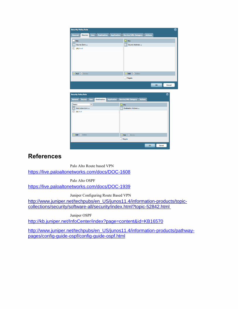
Configure the PA200 Security Policy
Create a security policy to permit traffic across the vpn tunnel. In this case both the
tunnel interface and the local LAN interface are in the same security zone, trust. Thus we
need a trust to trust policy to permit the communication. Here we create an open any
address to any protocol policy. These can be adjusted as desired to more tightly control
traffic.
You can also place the tunnel interface into a separate zone to allow a separate of policies
for communications with the vpn as opposed to the local zone.
Menu: Policies—Security: add button for new policy
References
Palo Alto Route based VPN
https://live.paloaltonetworks.com/docs/DOC-1608
Palo Alto OSPF
https://live.paloaltonetworks.com/docs/DOC-1939
Juniper Configuring Route Based VPN
http://www.juniper.net/techpubs/en_US/junos11.4/information-products/topic-collections/security/software-all/security/index.html?topic-52842.html
Juniper OSPF
http://kb.juniper.net/InfoCenter/index?page=content&id=KB16570
http://www.juniper.net/techpubs/en_US/junos11.4/information-products/pathway-pages/config-guide-ospf/config-guide-ospf.html