Embed Size (px)
Citation preview
PALLET JACK SCALE
USER’S MANUAL
(Pallet Jack Assembly & Indicator User Guide)
TABLE OF CONTENTSSafety Precautions 1
Preparations and Set Up 1
Installation Instructions 2-3
Features 4
Specifications 5
Pallet Jack Instructions 5
Power Supply 6
Display and Key Descriptions 7
Operating Instructions 8-10
Calibration 11-12
Indicator Parameter Settings 13-16
Helpful Definitions 17
Connectors 18
Troubleshooting 19
1
SAFETY PRECAUTIONS For safe operation of the weighing indicator, please follow these instructions: ● Calibration inspection and maintenance of the indicator are
prohibited by non-professional staff ● Please ensure that the indicator rests on a stable surface ● The indicator is a piece of static sensitive equipment; Please
cut off power during electrical connections ● Touching the internal components by hand is prohibited ● DO NOT exceed the rated load limit of the unit ● DO NOT step on the unit ● DO NOT jump on the scale ● DO NOT use this product if any of the components are
cracked ● DO NOT use for purposes other than weight taking ● To avoid damaging the battery do not keep charger plugged
in once battery is fully charged ● Make sure the weight is not over the max capacity as it could
damage the load cell inside ● Material that has a static electric charge could influence the
weighing. Discharge the static electricity of the samples, if possible. Another solution to the problem is to wipe both sides of the pan and the top of the case with an anti-static agent
Please take anti-static prevention measuresAny accumulated charge on the body of the human operator should be discharged first before opening the protective contain-er with ESDS devices inside. The discharge can be accomplished by: ● Putting a hand on a grounded surface or, ideally, by wearing
a grounded Anti-static Wrist Strap and an Anti-static Mat
PREPARATION & SET UP ● Plug into a wall outlet to avoid interference with other wirings ● Turn on the indicator while there is no load ● Calibration may be required before weighing when the scale
is initially installed or moved from a location
2
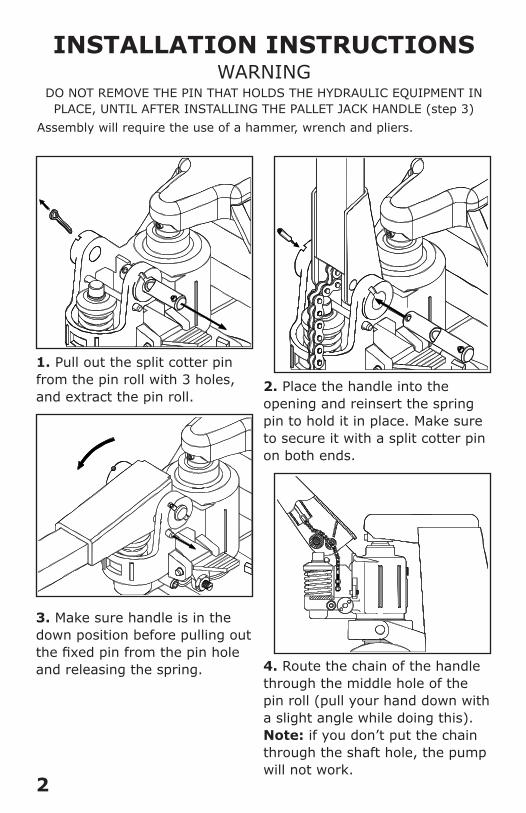
1. Pull out the split cotter pin from the pin roll with 3 holes, and extract the pin roll.
2. Place the handle into the opening and reinsert the spring pin to hold it in place. Make sure to secure it with a split cotter pin on both ends.
3. Make sure handle is in the down position before pulling out the fixed pin from the pin hole and releasing the spring.
INSTALLATION INSTRUCTIONS WARNING
DO NOT REMOVE THE PIN THAT HOLDS THE HYDRAULIC EQUIPMENT IN PLACE, UNTIL AFTER INSTALLING THE PALLET JACK HANDLE (step 3)
Assembly will require the use of a hammer, wrench and pliers.
4. Route the chain of the handle through the middle hole of the pin roll (pull your hand down with a slight angle while doing this). Note: if you don’t put the chain through the shaft hole, the pump will not work.
3
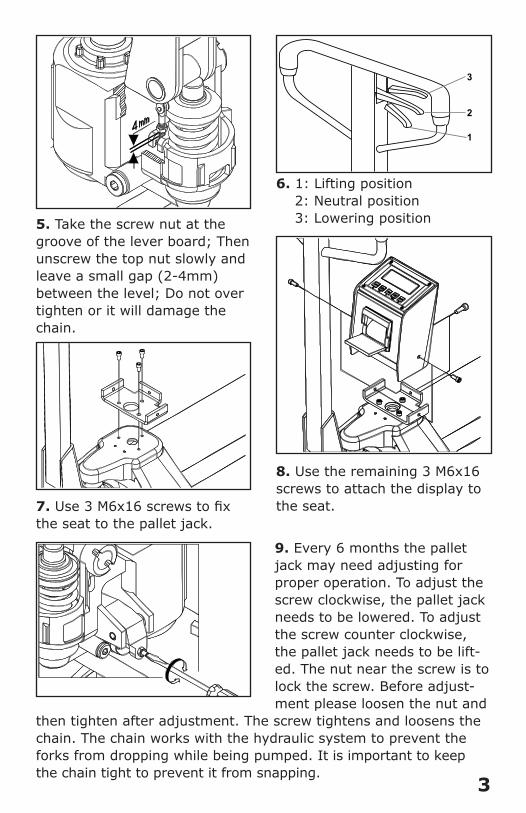
5. Take the screw nut at the groove of the lever board; Then unscrew the top nut slowly and leave a small gap (2-4mm) between the level; Do not over tighten or it will damage the chain.
1
2
3
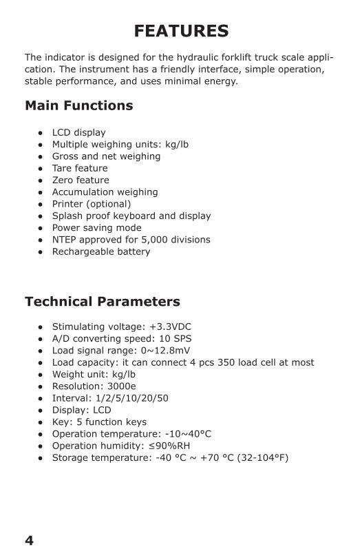
6. 1: Lifting position 2: Neutral position 3: Lowering position
9. Every 6 months the pallet jack may need adjusting for proper operation. To adjust the screw clockwise, the pallet jack needs to be lowered. To adjust the screw counter clockwise, the pallet jack needs to be lift-ed. The nut near the screw is to lock the screw. Before adjust-ment please loosen the nut and
then tighten after adjustment. The screw tightens and loosens the chain. The chain works with the hydraulic system to prevent the forks from dropping while being pumped. It is important to keep the chain tight to prevent it from snapping.
7. Use 3 M6x16 screws to fix the seat to the pallet jack.
8. Use the remaining 3 M6x16 screws to attach the display to the seat.
4
FEATURESThe indicator is designed for the hydraulic forklift truck scale appli-cation. The instrument has a friendly interface, simple operation, stable performance, and uses minimal energy.
Main Functions
● LCD display ● Multiple weighing units: kg/lb ● Gross and net weighing ● Tare feature ● Zero feature ● Accumulation weighing ● Printer (optional) ● Splash proof keyboard and display ● Power saving mode ● NTEP approved for 5,000 divisions ● Rechargeable battery
Technical Parameters
● Stimulating voltage: +3.3VDC ● A/D converting speed: 10 SPS ● Load signal range: 0~12.8mV ● Load capacity: it can connect 4 pcs 350 load cell at most ● Weight unit: kg/lb ● Resolution: 3000e ● Interval: 1/2/5/10/20/50 ● Display: LCD ● Key: 5 function keys ● Operation temperature: -10~40°C ● Operation humidity: ≤90%RH ● Storage temperature: -40 °C ~ +70 °C (32-104°F)
5
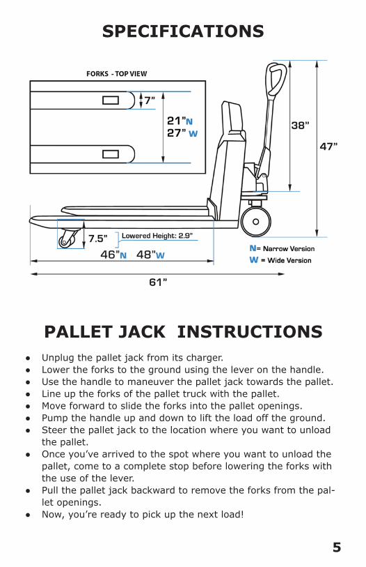
SPECIFICATIONS
PALLET JACK INSTRUCTIONS ● Unplug the pallet jack from its charger. ● Lower the forks to the ground using the lever on the handle. ● Use the handle to maneuver the pallet jack towards the pallet. ● Line up the forks of the pallet truck with the pallet. ● Move forward to slide the forks into the pallet openings. ● Pump the handle up and down to lift the load off the ground. ● Steer the pallet jack to the location where you want to unload
the pallet. ● Once you’ve arrived to the spot where you want to unload the
pallet, come to a complete stop before lowering the forks with the use of the lever.
● Pull the pallet jack backward to remove the forks from the pal-let openings.
● Now, you’re ready to pick up the next load!
6
POWER SUPPLY
AC Adapter
Please use the included adapter to charge your indicator. We rec-ommend to plug into a wall outlet to avoid interference with other wirings.
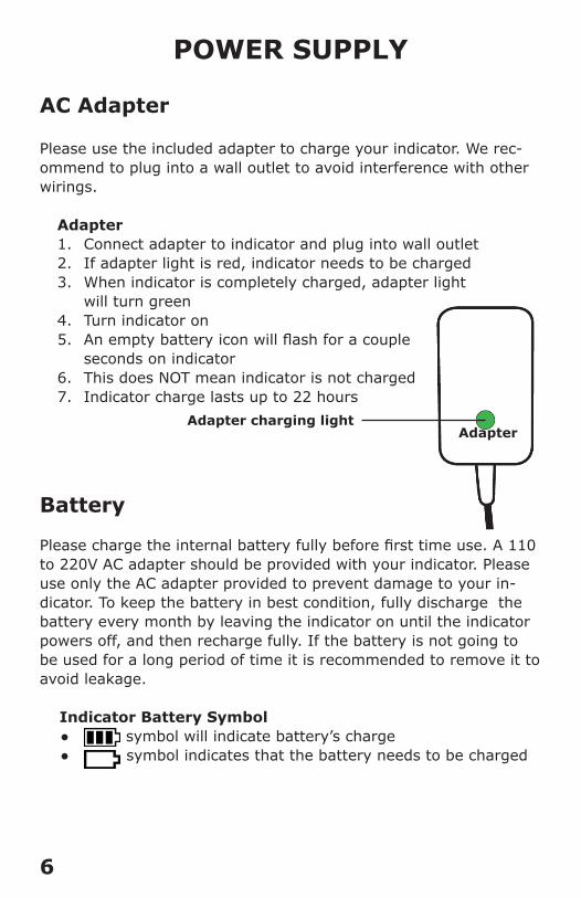
Adapter 1. Connect adapter to indicator and plug into wall outlet2. If adapter light is red, indicator needs to be charged3. When indicator is completely charged, adapter light
will turn green4. Turn indicator on5. An empty battery icon will flash for a couple
seconds on indicator6. This does NOT mean indicator is not charged7. Indicator charge lasts up to 22 hours
Battery
Please charge the internal battery fully before first time use. A 110 to 220V AC adapter should be provided with your indicator. Please use only the AC adapter provided to prevent damage to your in-dicator. To keep the battery in best condition, fully discharge the battery every month by leaving the indicator on until the indicator powers off, and then recharge fully. If the battery is not going to be used for a long period of time it is recommended to remove it to avoid leakage.
Indicator Battery Symbol ● symbol will indicate battery’s charge ● symbol indicates that the battery needs to be charged
Adapter charging lightAdapter
7
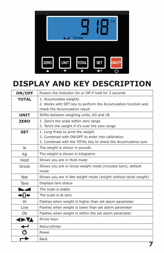
DISPLAY AND KEY DESCRIPTION ON/OFF Powers the Indicator On or Off if held for 3 seconds
TOTAL 1. Accumulates weights2. Works with SET key to perform the Accumulation function and check the Accumulation result
UNIT Shifts between weighing units, KG and LB
ZERO 1. Zero’s the scale within zero range2. Tare’s the weight if it’s over the zero range
SET 1. Long Press to print the weight2. Combined with ON/OFF to enter into calibration3. Combined with the TOTAL key to check the Accumulative sum
lb The weight is shown in pounds
kg The weight is shown in kilograms
Hold Shows you are in Hold mode
Gross Shows you are in Gross weight mode (includes tare); default mode
Net Shows you are in Net weight mode (weight without tared weight)
Tare Displays tare status
The scale is stable
The scale is at zero
Hi Flashes when weight is higher than set alarm parameter
Low Flashes when weight is lower than set alarm parameter
Ok Flashes when weight is within the set alarm parameter
Arrow keys
Return/Enter
Power
Back
8
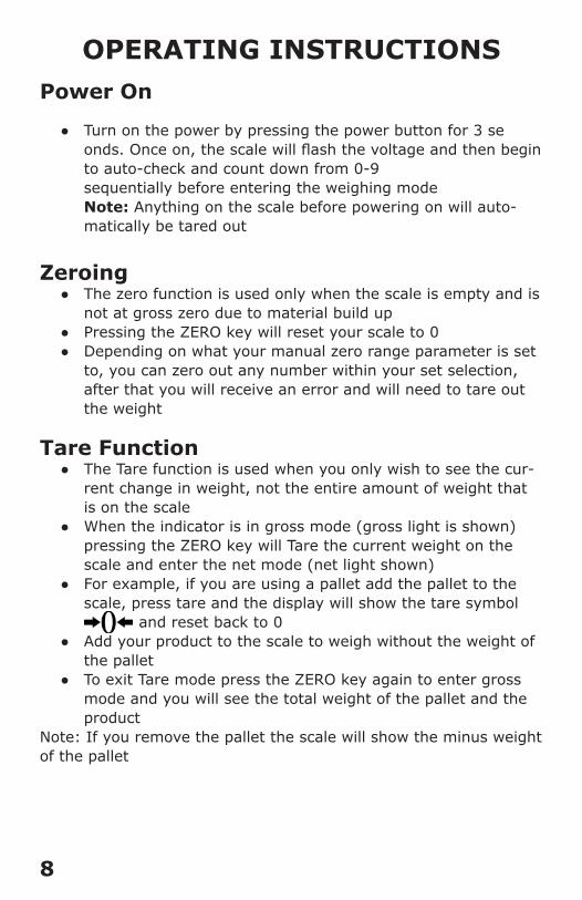
OPERATING INSTRUCTIONSPower On
● Turn on the power by pressing the power button for 3 se onds. Once on, the scale will flash the voltage and then begin to auto-check and count down from 0-9 sequentially before entering the weighing mode Note: Anything on the scale before powering on will auto-matically be tared out
Zeroing ● The zero function is used only when the scale is empty and is
not at gross zero due to material build up ● Pressing the ZERO key will reset your scale to 0 ● Depending on what your manual zero range parameter is set
to, you can zero out any number within your set selection, after that you will receive an error and will need to tare out the weight
Tare Function ● The Tare function is used when you only wish to see the cur-
rent change in weight, not the entire amount of weight that is on the scale
● When the indicator is in gross mode (gross light is shown) pressing the ZERO key will Tare the current weight on the scale and enter the net mode (net light shown)
● For example, if you are using a pallet add the pallet to the scale, press tare and the display will show the tare symbol
and reset back to 0 ● Add your product to the scale to weigh without the weight of
the pallet ● To exit Tare mode press the ZERO key again to enter gross
mode and you will see the total weight of the pallet and the product
Note: If you remove the pallet the scale will show the minus weight of the pallet
9
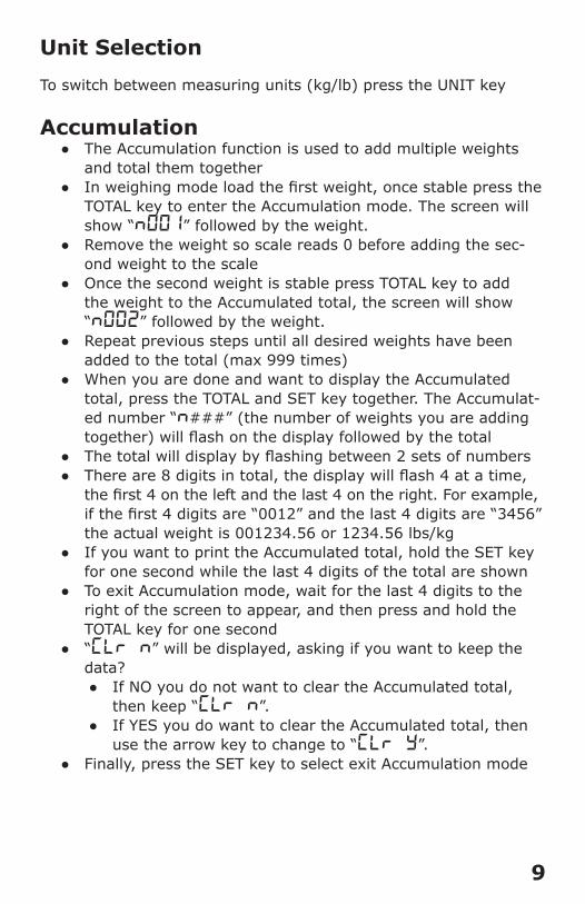
Unit Selection
To switch between measuring units (kg/lb) press the UNIT key
Accumulation ● The Accumulation function is used to add multiple weights
and total them together ● In weighing mode load the first weight, once stable press the
TOTAL key to enter the Accumulation mode. The screen will show “n001” followed by the weight.
● Remove the weight so scale reads 0 before adding the sec-ond weight to the scale
● Once the second weight is stable press TOTAL key to add the weight to the Accumulated total, the screen will show “n002” followed by the weight.
● Repeat previous steps until all desired weights have been added to the total (max 999 times)
● When you are done and want to display the Accumulated total, press the TOTAL and SET key together. The Accumulat-ed number “n###” (the number of weights you are adding together) will flash on the display followed by the total
● The total will display by flashing between 2 sets of numbers ● There are 8 digits in total, the display will flash 4 at a time,
the first 4 on the left and the last 4 on the right. For example, if the first 4 digits are “0012” and the last 4 digits are “3456” the actual weight is 001234.56 or 1234.56 lbs/kg
● If you want to print the Accumulated total, hold the SET key for one second while the last 4 digits of the total are shown
● To exit Accumulation mode, wait for the last 4 digits to the right of the screen to appear, and then press and hold the TOTAL key for one second
● “CLr n” will be displayed, asking if you want to keep the data?
● If NO you do not want to clear the Accumulated total, then keep “CLr n”.
● If YES you do want to clear the Accumulated total, then use the arrow key to change to “CLr y”.
● Finally, press the SET key to select exit Accumulation mode
10
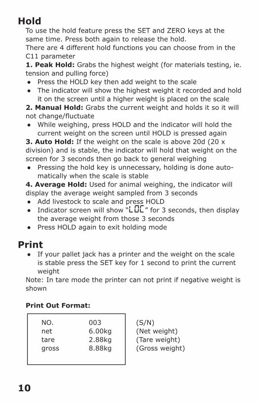
HoldTo use the hold feature press the SET and ZERO keys at the same time. Press both again to release the hold. There are 4 different hold functions you can choose from in the C11 parameter1. Peak Hold: Grabs the highest weight (for materials testing, ie. tension and pulling force)
● Press the HOLD key then add weight to the scale ● The indicator will show the highest weight it recorded and hold
it on the screen until a higher weight is placed on the scale2. Manual Hold: Grabs the current weight and holds it so it will not change/fluctuate
● While weighing, press HOLD and the indicator will hold the current weight on the screen until HOLD is pressed again
3. Auto Hold: If the weight on the scale is above 20d (20 x division) and is stable, the indicator will hold that weight on the screen for 3 seconds then go back to general weighing
● Pressing the hold key is unnecessary, holding is done auto-matically when the scale is stable
4. Average Hold: Used for animal weighing, the indicator will display the average weight sampled from 3 seconds
● Add livestock to scale and press HOLD ● Indicator screen will show “LOC” for 3 seconds, then display
the average weight from those 3 seconds ● Press HOLD again to exit holding mode
Print ● If your pallet jack has a printer and the weight on the scale
is stable press the SET key for 1 second to print the current weight
Note: In tare mode the printer can not print if negative weight is shown
Print Out Format:
NO. 003 (S/N) net 6.00kg (Net weight) tare 2.88kg (Tare weight) gross 8.88kg (Gross weight)
11
PALLET JACKCALIBRATION PROCEDURE
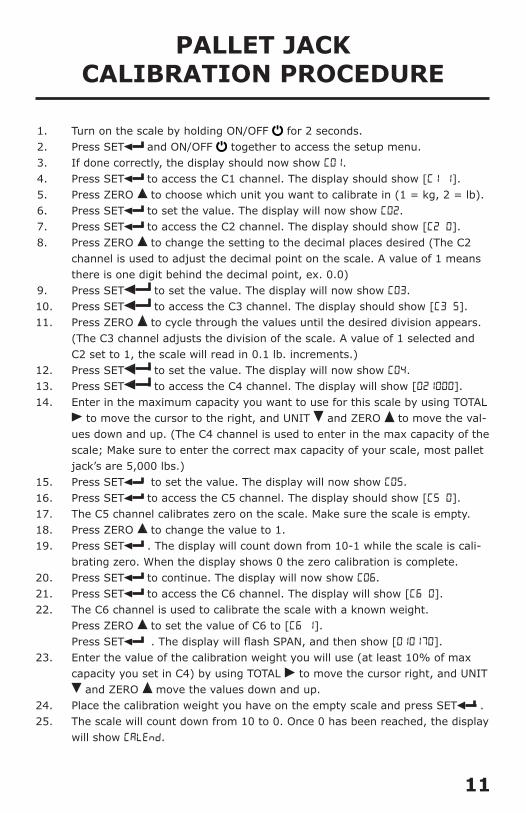
1. Turn on the scale by holding ON/OFF for 2 seconds. 2. Press SET and ON/OFF together to access the setup menu.3. If done correctly, the display should now show C01.4. Press SET to access the C1 channel. The display should show [C1 1].5. Press ZERO to choose which unit you want to calibrate in (1 = kg, 2 = lb).6. Press SET to set the value. The display will now show C02. 7. Press SET to access the C2 channel. The display should show [C2 0].8. Press ZERO to change the setting to the decimal places desired (The C2
channel is used to adjust the decimal point on the scale. A value of 1 means there is one digit behind the decimal point, ex. 0.0)
9. Press SET to set the value. The display will now show C03.10. Press SET to access the C3 channel. The display should show [C3 5].11. Press ZERO to cycle through the values until the desired division appears.
(The C3 channel adjusts the division of the scale. A value of 1 selected and C2 set to 1, the scale will read in 0.1 lb. increments.)
12. Press SET to set the value. The display will now show C04.13. Press SET to access the C4 channel. The display will show [021000].14. Enter in the maximum capacity you want to use for this scale by using TOTAL
to move the cursor to the right, and UNIT and ZERO to move the val-ues down and up. (The C4 channel is used to enter in the max capacity of the scale; Make sure to enter the correct max capacity of your scale, most pallet jack’s are 5,000 lbs.)
15. Press SET to set the value. The display will now show C05.16. Press SET to access the C5 channel. The display should show [C5 0].17. The C5 channel calibrates zero on the scale. Make sure the scale is empty.18. Press ZERO to change the value to 1.19. Press SET . The display will count down from 10-1 while the scale is cali-
brating zero. When the display shows 0 the zero calibration is complete.20. Press SET to continue. The display will now show C06.21. Press SET to access the C6 channel. The display will show [C6 0].22. The C6 channel is used to calibrate the scale with a known weight.
Press ZERO to set the value of C6 to [C6 1]. Press SET . The display will flash SPAN, and then show [010170].
23. Enter the value of the calibration weight you will use (at least 10% of max capacity you set in C4) by using TOTAL to move the cursor right, and UNIT
and ZERO move the values down and up.24. Place the calibration weight you have on the empty scale and press SET .25. The scale will count down from 10 to 0. Once 0 has been reached, the display
will show CALEnd.
12
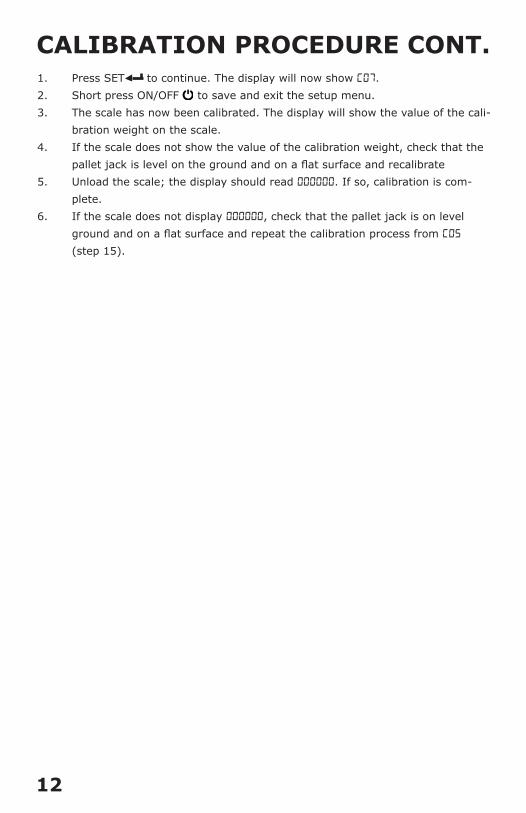
1. Press SET to continue. The display will now show C07.2. Short press ON/OFF to save and exit the setup menu.3. The scale has now been calibrated. The display will show the value of the cali-
bration weight on the scale.4. If the scale does not show the value of the calibration weight, check that the
pallet jack is level on the ground and on a flat surface and recalibrate5. Unload the scale; the display should read 000000. If so, calibration is com-
plete.6. If the scale does not display 000000, check that the pallet jack is on level
ground and on a flat surface and repeat the calibration process from C05 (step 15).
CALIBRATION PROCEDURE CONT.
13
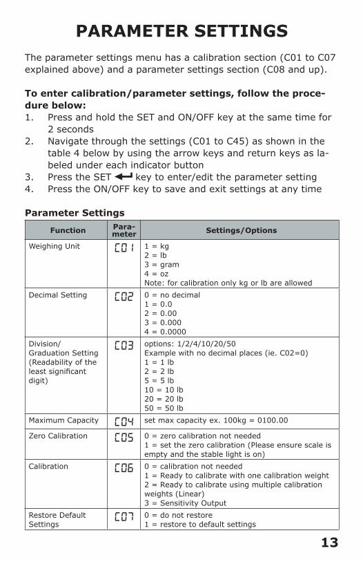
PARAMETER SETTINGSThe parameter settings menu has a calibration section (C01 to C07 explained above) and a parameter settings section (C08 and up).
To enter calibration/parameter settings, follow the proce-dure below:1. Press and hold the SET and ON/OFF key at the same time for
2 seconds2. Navigate through the settings (C01 to C45) as shown in the
table 4 below by using the arrow keys and return keys as la-beled under each indicator button
3. Press the SET key to enter/edit the parameter setting4. Press the ON/OFF key to save and exit settings at any time
Parameter Settings
Function Para-meter Settings/Options
Weighing Unit C01 1 = kg2 = lb3 = gram4 = ozNote: for calibration only kg or lb are allowed
Decimal Setting C02 0 = no decimal1 = 0.02 = 0.003 = 0.0004 = 0.0000
Division/Graduation Setting(Readability of the least significant digit)
C03 options: 1/2/4/10/20/50 Example with no decimal places (ie. C02=0)1 = 1 lb2 = 2 lb5 = 5 lb10 = 10 lb20 = 20 lb50 = 50 lb
Maximum Capacity C04 set max capacity ex. 100kg = 0100.00
Zero Calibration C05 0 = zero calibration not needed1 = set the zero calibration (Please ensure scale is empty and the stable light is on)
Calibration C06 0 = calibration not needed1 = Ready to calibrate with one calibration weight2 = Ready to calibrate using multiple calibration weights (Linear)3 = Sensitivity Output
Restore DefaultSettings
C07 0 = do not restore1 = restore to default settings
14
Function Para-meter Settings/Options
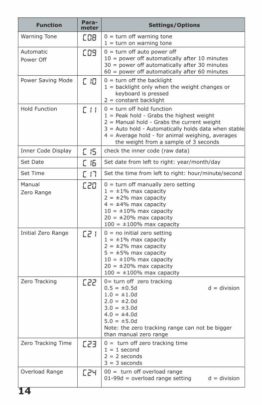
Warning Tone C08 0 = turn off warning tone1 = turn on warning tone
Automatic Power Off
C09 0 = turn off auto power off10 = power off automatically after 10 minutes30 = power off automatically after 30 minutes60 = power off automatically after 60 minutes
Power Saving Mode C10 0 = turn off the backlight 1 = backlight only when the weight changes or keyboard is pressed2 = constant backlight
Hold Function C11 0 = turn off hold function1 = Peak hold - Grabs the highest weight2 = Manual hold - Grabs the current weight3 = Auto hold - Automatically holds data when stable4 = Average hold - for animal weighing, averages the weight from a sample of 3 seconds
Inner Code Display C15 check the inner code (raw data)
Set Date C16 Set date from left to right: year/month/day
Set Time C17 Set the time from left to right: hour/minute/second
ManualZero Range
C20 0 = turn off manually zero setting1 = ±1% max capacity2 = ±2% max capacity4 = ±4% max capacity10 = ±10% max capacity20 = ±20% max capacity100 = ±100% max capacity
Initial Zero Range C21 0 = no initial zero setting1 = ±1% max capacity2 = ±2% max capacity5 = ±5% max capacity10 = ±10% max capacity20 = ±20% max capacity100 = ±100% max capacity
Zero Tracking C22 0= turn off zero tracking0.5 = ±0.5d d = division1.0 = ±1.0d2.0 = ±2.0d3.0 = ±3.0d4.0 = ±4.0d5.0 = ±5.0dNote: the zero tracking range can not be bigger than manual zero range
Zero Tracking Time C23 0 = turn off zero tracking time1 = 1 second2 = 2 seconds3 = 3 seconds
Overload Range C24 00 = turn off overload range01-99d = overload range setting d = division
15
FunctionPara-meter
Settings/Options
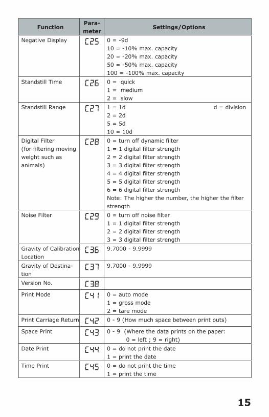
Negative Display C25 0 = -9d10 = -10% max. capacity20 = -20% max. capacity50 = -50% max. capacity100 = -100% max. capacity
Standstill Time C26 0 = quick1 = medium2 = slow
Standstill Range C27 1 = 1d d = division2 = 2d 5 = 5d 10 = 10d
Digital Filter (for filtering moving weight such as animals)
C28 0 = turn off dynamic filter1 = 1 digital filter strength2 = 2 digital filter strength3 = 3 digital filter strength4 = 4 digital filter strength5 = 5 digital filter strength6 = 6 digital filter strengthNote: The higher the number, the higher the filter strength
Noise Filter C29 0 = turn off noise filter1 = 1 digital filter strength2 = 2 digital filter strength3 = 3 digital filter strength
Gravity of Calibration Location
C36 9.7000 - 9.9999
Gravity of Destina-tion
C37 9.7000 - 9.9999
Version No. C38
Print Mode C41 0 = auto mode1 = gross mode2 = tare mode
Print Carriage Return C42 0 - 9 (How much space between print outs)
Space Print C43 0 - 9 (Where the data prints on the paper: 0 = left ; 9 = right)
Date Print C44 0 = do not print the date1 = print the date
Time Print C45 0 = do not print the time1 = print the time
16
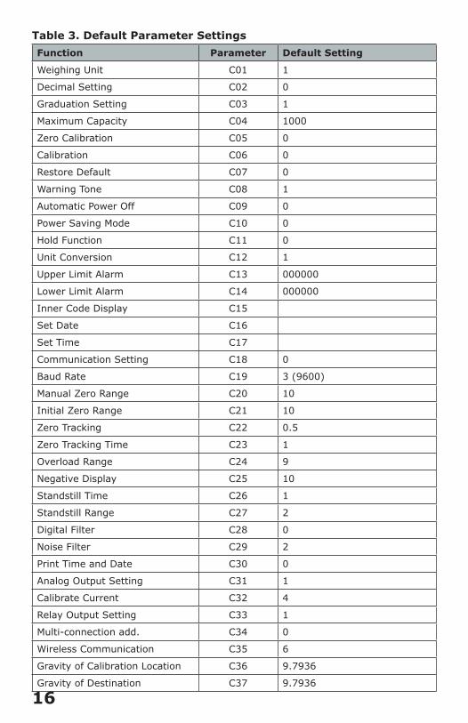
Table 3. Default Parameter Settings Function Parameter Default Setting
Weighing Unit C01 1
Decimal Setting C02 0
Graduation Setting C03 1
Maximum Capacity C04 1000
Zero Calibration C05 0
Calibration C06 0
Restore Default C07 0
Warning Tone C08 1
Automatic Power Off C09 0
Power Saving Mode C10 0
Hold Function C11 0
Unit Conversion C12 1
Upper Limit Alarm C13 000000
Lower Limit Alarm C14 000000
Inner Code Display C15
Set Date C16
Set Time C17
Communication Setting C18 0
Baud Rate C19 3 (9600)
Manual Zero Range C20 10
Initial Zero Range C21 10
Zero Tracking C22 0.5
Zero Tracking Time C23 1
Overload Range C24 9
Negative Display C25 10
Standstill Time C26 1
Standstill Range C27 2
Digital Filter C28 0
Noise Filter C29 2
Print Time and Date C30 0
Analog Output Setting C31 1
Calibrate Current C32 4
Relay Output Setting C33 1
Multi-connection add. C34 0
Wireless Communication C35 6
Gravity of Calibration Location C36 9.7936
Gravity of Destination C37 9.7936
17
HELPFUL DEFINITIONSDivision: The amount of increments a scale offers; how accurate the scale can beCapacity: the maximum amount the scale can containInitial Zero Range: The percentage of weight allowed on the scale when indicator is powered on that will automatically zero. example: If initial zero range is set to 10% of the max. capaci-ty and your max. capacity is 100lbs, you can place up to 10lbs of weight on the scale and when the indicator is powered on, it will automatically zero out the weight. Manual Zero Range: The percentage of weight allowed on the scale where the indicator will let you manually zero (anything above this percent will be tared)Zero Tracking Range: A subset to the manual zero range; if the weight on the scale is not stable, the zero tracking range still al-lows you to zero within a set division of the scaleZero Tracking Time: A subset to the zero tracking range, it is the time allowed for the scale to fall within the zero tracking range tolerance and still qualify to be zero’dOverload Range: Weight allowance that is out of the set calibrat-ed range. Adds a tolerance to the calibrated max. capacity without having to recalibrate. example: If your scale has a max. capacity of 1000lbs with a division of 1 and you set the overload range to 60, you can add 1060lbs of weight to the scale without it displaying an error codeNegative Display: How far you can go in the negative direction before displaying an error codeStandstill Time: How fast the scale will stabilize Standstill Range: How much the scale can fluctuate before being determined stableDigital Filter: For filtering moving weight, such as animals, It changes how sensitive the scale is to variations in movement. Noise Filter: A filter for how susceptible the scale is to general variationsBaud Rate: The rate at which information is transferred in a com-munication channel. example: In the serial port context, “9600 baud” means that the serial port is capable of transferring a maxi-mum of 9600 bits per second.
18
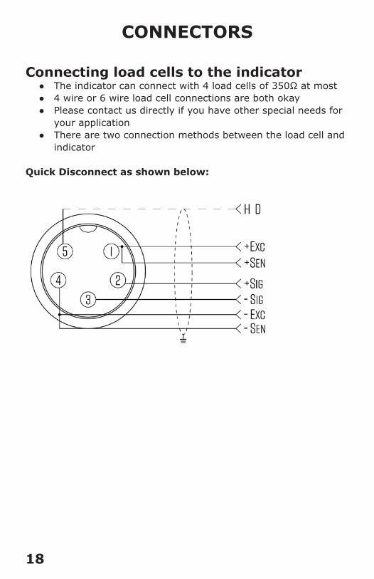
CONNECTORS
Connecting load cells to the indicator ● The indicator can connect with 4 load cells of 350Ω at most ● 4 wire or 6 wire load cell connections are both okay ● Please contact us directly if you have other special needs for
your application ● There are two connection methods between the load cell and
indicator
Quick Disconnect as shown below:
19
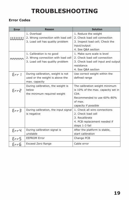
TROUBLESHOOTINGError Codes
Error Reason Solution
UUUUUU
1. Overload2. Wrong connection with load cell3. Load cell has quality problem
1. Reduce the weight2. Check load cell connection3. Inspect load cell; Check the input/output4. See Q&A section
nnnnnn
1. Calibration is no good2. Wrong connection with load cell3. Load cell has quality problem
1. Make sure scale is level2. Check load cell connection3. Check load cell input and output resistance4. See Q&A section
ERR1 During calibration, weight is not used or the weight is above the max. capacity
Use correct weight within the defined range
ERR2
During calibration, the weight is below the minimum required weight
The calibration weight minimum is 10% of the max. capacity set in C04. Recommended to use 60%-80% of max. capacity if possible
ERR3 During calibration, the input signal is negative
1. Check all wire connections2. Check load cell3. Recalibrate4. PCB replacement needed if steps 1-3 fail
ERR4 During calibration signal is unstable
After the platform is stable, start calibration
ERR5 EEPROM Error Change PCB
ERR6 Exceed Zero Range Cable error