Embed Size (px)
Citation preview

1Paired Ladder Safety Gate-All Models © PS INDUSTRIES INCORPORATED 2018. All Rights Reserved.
Rev112018
PN 510978 B
PAIRED LADDER SAFETY GATEInstallation Instructions/Operation and Maintenance Manual
IMPORTANT! Read entire Instruction and Operations Manual to become familiar with the product.
NOTICE This product is a fall protection product. The effectiveness of the product is directly related to the proper installation and operation of this product. Failure to properly maintain this product will affect performance.
Publication NoticeThis manual has been compiled and published covering the latest product descriptions and specifications.
The contents of this manual and the specifications of this product are subject to change without notice.
PS Safety Access reserves the right to make changes without notice in the specifications and materials contained herein and shall not be responsible for any damages (including consequential) caused by reliance on the materialspresented, including but not limited to typographical and other errors relating to the publication.
PS Safety Access and/or its respective suppliers may make improvements and/or changes in the product(s)/service(s) offered and/or the program(s) at any time without notice.
Retain this manual for future reference.If you would like to download a copy of this manual, please go to pssafetyaccess.com
MailPS Safety Access1150 South 48th StreetGrand Forks, ND 58201
Websitepssafetyaccess.com
Local Phone701.746.4519
Toll Free Phone877.446.1519
Hours of Operation8 A.M. to 5 P.M. CTMonday – Friday
Table of Contents:Safety Precautions ............................................................. 2Product Information ........................................................... 2Support Channel Installation ............................................ 4Installation on Angle Iron/Flat Bar, or Wall Surface ........ 7Replacement Parts List ..................................................... 8Inspection and Maintenance............................................. 9 Warranty Certificate .........................................................11
Models: All Models
Contact Information

2Paired Ladder Safety Gate-All Models © PS INDUSTRIES INCORPORATED 2018. All Rights Reserved.
Rev112018
NOTICE Unauthorized modification of or to the product voids this Limited Warranty. Authorized modifications, received in writing from PS INDUSTRIES INCORPORATED, as long as the modification is accomplished in strict accordance with PS INDUSTRIES INCORPORATED’s instructions, does not void warranty. To request product modifications contact PS INDUSTRIES INCORPORATED, 1150 S. 48th Street, Grand Forks, ND 58201, phone 877-446-1519, email: [email protected]
I. General InformationA. This manual contains information regarding installation, operation, and maintenance of the PS INDUSTRIES
INCORPORATED’s Paired Ladder Safety Gate.B. The Paired Ladder Safety Gate is designed meet OSHA Railing Standard 1910.29(b).C. PS INDUSTRIES INCORPORATED recommends that the owner implement a regular maintenance program to
inspect the Paired Ladder Safety Gate as necessary.D. Operation in a manner other than intended could result in damage or less than acceptable performance at
time of need, for which the manufacturer will not be held responsible.
II. Storage Prior to Installation of ProductA. Store materials in a dry, ventilated location. If outdoor storage is required, block materials and tarp in a tent-like
arrangement, elevated above the product with open sides to allow airflow.
III. Installation Site Preparation
NOTICE Before starting site preparation and installation of the Paired Ladder Safety Gate, read the entire Operation and Maintenance Manual and review all installation instructions thoroughly.
A. Clear work area of any debris.B. Ensure you have the necessary tools available.
IV. Pre-Installation Safety Precautions A. Ensure opening is clear of all obstructions through the entire proposed travel of the Paired Ladder Safety Gate during operation. B. Comply with all OSHA and ANSI Safety Regulations and/or company safety policies when installing. C. Personnel: Determine the appropriate number of personnel required to perform installation and have them readily available at the project site. (1-2 people recommended)
DANGER Ensure area below installation is blocked off from personnel during installation, and mounting surface is capable of supporting all loading. Structural analysis of mounting surface is the responsibility of the owner.
Paired Ladder Safety Gate Product Information
The following icons are used throughout this Manual.
DANGER Indicates an imminently hazardous situation which, if not avoided, will result in death or serious injury. WARNING Indicates a potentially hazardous situation which, if not avoided, could result in death or serious injury. CAUTION Indicates a potentially hazardous situation which, if not avoided, may result in minor or moderated injury.
NOTICE Indicates manufacturer’s statement of additional information.IMPORTANT! Indicates a required action.CRITICAL Indicates a vital component to product performance.
Safety Precautions

3Paired Ladder Safety Gate-All Models © PS INDUSTRIES INCORPORATED 2018. All Rights Reserved.
Rev112018
Recommended Tools: 1. One (1) 1/2” Deep-well Socket and Ratchet 2. One (1) Wrench Set 3. One (1) Electric Drill 4. One (1) 11/32” Drill Bit 5. One (1) Tape Measure
Paired Ladder Safety Gate Part List(As shipped)
ITEM NUMBER DESCRIPTION QUANTITY
1* LSG;HINGEPLT ASSY 22* LSG;HOOP 23* BOLT;CARRIAGE5/16”18X2 8
4* WASHER;FLAT 5/16” 85* NUT;NYLOCK 5/16” 86 LSG;RAILING SUPPORT CHAN 27 LSGDBL;HARDWARE BAG 2
8 DBLLSG;Installation/O&M Manual 1
(2) Ladder Safety Gate(pre-assembled)
V. OperationA. When ascending a ladder/entering the elevated platform: 1. When the gate opening is reached, obtain a firm grip on the railing or ladder. 2. Step through gate. 3. DO NOT USE THE LADDER SAFETY GATE AS A GRAB SURFACE.B. When descending a ladder/exiting the elevated platform. 1. Open the Ladder Safety Gate and obtain firm grip on railing. 2. Maneuver yourself into the proper ladder descending position. DO NOT USE THE LADDER SAFETY GATE AS A
GRAB SURFACE. 3. Always maintain a firm grip on the railing or ladder.
*Item numbers 1 - 5 come pre-assembled.
Paired Ladder Safety Gate Product Information
NOTE: Inventory carton to ensure all parts are present for assembly/installation. Refer to part list below.

4Paired Ladder Safety Gate-All Models © PS INDUSTRIES INCORPORATED 2018. All Rights Reserved.
Rev112018
SupportChannel
3 5/8"
3 5/8"
7 5/8"
Support Channel Installation
VI. Support Channel Installation
STEP 1. Locate the Support Channel on the railing. a. The distance from the top of the Support Channel to the desired top of the Gate is 3 5/8”. If no railing,
adjust top of hoop/gate arm to 42” above walking surface. b. Align Support Channel parallel to the desired opening to ensure proper installation.
Step 1Illustration A
Step 1Illustration B
STEP 2. Match drill holes into the railing using 11/32” drill bit (Supplied by others, NOT PS Safety Access).
Step 2Illustration
Align gate to the top of railing

5Paired Ladder Safety Gate-All Models © PS INDUSTRIES INCORPORATED 2018. All Rights Reserved.
Rev112018
SupportChannel
8.5
STEP 3. Insert the 5/16” hex bolts through the bailing, loosely securing the Support Channel to the railing.
Step 3Illustration
Support Channel Installation
8.3
STEP 4. Loosely attach the Ladder Safety Gate to the railing with the 5/16” U-Bolts. *Do not tighten, additional adjustment may be required.
Step 4Illustration A
Step 4Illustration B
8.1 8.2 8.3
STEP 5. Repeat steps 1-4 for the other Ladder Safety Gate Assembly.
6Paired Ladder Safety Gate-All Models © PS INDUSTRIES INCORPORATED 2018. All Rights Reserved.
Rev112018
Hole Locations for desired gate width
Hole Locations for desired gate width
1" Clearance
90.0o
Support Channel Installation
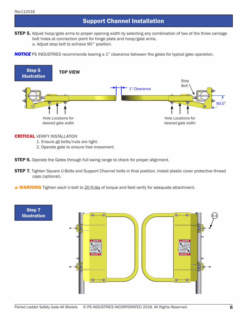
STEP 5. Adjust hoop/gate arms to proper opening width by selecting any combination of two of the three carriage bolt holes at connection point for hinge plate and hoop/gate arms.
a. Adjust stop bolt to achieve 90° position.
NOTICE PS INDUSTRIES recommends leaving a 1” clearance between the gates for typical gate operation.
Step 5Illustration
CRITICAL VERIFY INSTALLATION 1. Ensure all bolts/nuts are tight. 2. Operate gate to ensure free movement.
STEP 6. Operate the Gates through full swing range to check for proper alignment.
STEP 7. Tighten Square U-Bolts and Support Channel bolts in final position. Install plastic cover protective thread caps (optional).
WARNING Tighten each U-bolt to 20 ft-lbs of torque and field verify for adequate attachment.
Step 7Illustration 8.4
TOP VIEW
StopBolt
7Paired Ladder Safety Gate-All Models © PS INDUSTRIES INCORPORATED 2018. All Rights Reserved.
Rev112018
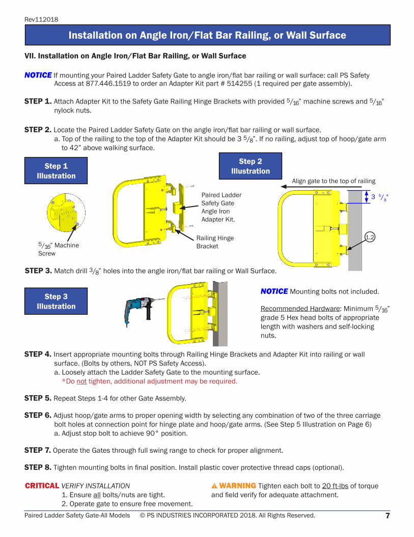
3 5/8"Paired Ladder Safety Gate Angle Iron Adapter Kit.
Railing Hinge Bracket
Installation on Angle Iron/Flat Bar Railing, or Wall Surface
VII. Installation on Angle Iron/Flat Bar Railing, or Wall Surface
NOTICE If mounting your Paired Ladder Safety Gate to angle iron/flat bar railing or wall surface: call PS Safety Access at 877.446.1519 to order an Adapter Kit part # 514255 (1 required per gate assembly).
STEP 1. Attach Adapter Kit to the Safety Gate Railing Hinge Brackets with provided 5/16” machine screws and 5/16” nylock nuts.
STEP 2. Locate the Paired Ladder Safety Gate on the angle iron/flat bar railing or wall surface. a. Top of the railing to the top of the Adapter Kit should be 3 5/8”. If no railing, adjust top of hoop/gate arm
to 42” above walking surface.
Step 1Illustration
1.2
STEP 3. Match drill 3/8” holes into the angle iron/flat bar railing or Wall Surface.
Step 3Illustration
CRITICAL VERIFY INSTALLATION 1. Ensure all bolts/nuts are tight. 2. Operate gate to ensure free movement.
WARNING Tighten each bolt to 20 ft-lbs of torque and field verify for adequate attachment.
NOTICE Mounting bolts not included.
Recommended Hardware: Minimum 5/16” grade 5 Hex head bolts of appropriate length with washers and self-locking nuts.
Step 2Illustration
STEP 4. Insert appropriate mounting bolts through Railing Hinge Brackets and Adapter Kit into railing or wall surface. (Bolts by others, NOT PS Safety Access).
a. Loosely attach the Ladder Safety Gate to the mounting surface. *Do not tighten, additional adjustment may be required.
STEP 5. Repeat Steps 1-4 for other Gate Assembly.
STEP 6. Adjust hoop/gate arms to proper opening width by selecting any combination of two of the three carriage bolt holes at connection point for hinge plate and hoop/gate arms. (See Step 5 Illustration on Page 6)
a. Adjust stop bolt to achieve 90° position.
STEP 7. Operate the Gates through full swing range to check for proper alignment.
STEP 8. Tighten mounting bolts in final position. Install plastic cover protective thread caps (optional).
Align gate to the top of railing
5/16” MachineScrew

8Paired Ladder Safety Gate-All Models © PS INDUSTRIES INCORPORATED 2018. All Rights Reserved.
Rev112018
1.265
8.1
1.5
1.44
8.28.3
8.4
8.5 8.3
1011
1.6
1.4
3
1.3
7
1.1
2
*9” & 12” Paired Ladder Safety Gate Sizes have mitered Hoop/Gate Arm.
VIII. Replacement Parts List
NOTE 1. Paired Ladder Safety Gate is shipped fully assembled. Diagram is for part identification only.
NOTE 2. This diagram is for all Paired Ladder Safety Gate PCY/GAL/SS Models.
Replacement Parts List
FINISH OPTIONSSS Stainless Steel
PCY Powder Coat Safety Yellow
GAL Hot Dipped Galvanized
**For replacement springs, order Torsion Spring Kit (part #511686.) Kit includes (1)LSG Torsion Spring,
(2)Bushings and Installation Instructions.
TO ORDER PARTS CONTACT PS SAFETY ACCESS AT877.446.1519 or [email protected]
GATE FINISH TYPEITEM # DESCRIPTION QTY SS PCY GAL
1 LSG;GATE STOP HING PLT ASM 2 510846 510410 510123
1.1 LSG;GATE STOP HINGE PLT WLD 2 510849 510409 510367
1.2 LSG;RAILING BRACKET 4 501007 501006 501004
1.3 LSG;TORSION SPRIN, ST. STL** 4 501659 501659 501659
1.4 BEARING;G300 FLANGE, .3125ID 8 509753 509753 509753
1.5 NUT;NYLOCK 5/16”-18 4 501121 501126 501226
1.6 BOLT;HEX5/16”18X3 4 500433 500431 500431
2 LSG;HOOP/GATE ARM-XX 2 PART # DEPENDENT ON SIZE OF GATE. CONSULT FACTORY.
3 BOLT;CARRIAGE5/16” 18X2” 4 509980 500326 500326
4 WASHER, FLAT 5/16” 8 501948 501949 501949
5 NUT;NYLOCK 5/16”-18 8 501121 501126 501126
6 LSG;RAILING SUPPORT CHANNEL 2 510844 510413 510128
7 DECAL;LSG ANSI DANGER 4 500569 500569 500569
8 LSGDBL;HARDWARE BAG 2 510420 510396 510396
8.1 BOLT;SQU 5/16”18X4 PIPE 2 510421 510125 510125
8.2 WASHER, FLAT 5/16” 4 501948 501949 501949
8.3 NUT;NYLOCK 5/16”-18 6 501121 501126 501126
8.4 LSG;CAP PLASTIC FOR 5/16 BOLT 4 500932 500932 500932
8.5 BOLT;HEX5/16”18X3-1/4 2 511485 502710 502710
9 DBLLSG;INSTALLATION/O&M MANUAL 1 510978 510978 510978
10 BOLT;CARRIAGE 1/2”13X3 1/2 2 503293 500315 500315
11 NUT;FLANGE 1/2”13 2 503936 502903 502903

9Paired Ladder Safety Gate-All Models © PS INDUSTRIES INCORPORATED 2018. All Rights Reserved.
Rev112018
IX. Inspection and Maintenance (Minimum Annually)
IMPORTANT! Consult parts list before replacing fasteners, as all have specific design load requirements. Only use like items for replacement.
A. Paired Ladder Safety Gate: 1. Inspect components for damage and misalignment. Adjust, repair, or replace as needed, to meet original design tolerance. 2. Check gates for proper alignment with catch. Adjust as necessary to achieve proper alignment.
B. Fasteners and mechanical connections1. All fasteners must be in place and adjusted to their original design standard. Replace any damaged components.2. Check all mounting connections, making sure they meet original design standards (refer to instructions).
C. Finishes 1. Inspect and clean finishes periodically. 2. Touch up repair finishes, or refinish as necessary to protect the structural integrity of the Paired Ladder Safety
Gate. 3. The PCY Paired Ladder Safety Gate comes with a polyester powder coat finish. Use finish materials compatible
with powder coat. Follow paint manufacturers’ instructions for prep and touch-up.
D. Housekeeping 1. To ensure your product continues to operate and last, upon completion of proper installation, complete the
following: a. Clean all surfaces. b. If project is ongoing, protect installed products until final completion of project. c. Touch-up, repair, or replace damaged components. 2. Ensure the area is clear of debris and interferences while swinging the gates.
E. Labels and Placards: 1. Inspect all labels and placards. 2. Replace any labels and placards which are unreadable/missing.
Inspection and Maintenance

10Paired Ladder Safety Gate-All Models © PS INDUSTRIES INCORPORATED 2018. All Rights Reserved.
Rev112018
Insp
ecti
on a
nd M
aint
enan
ce L
og
CR
ITIC
AL P
erio
dic
Insp
ectio
n an
d M
aint
enan
ce R
equi
red.
Ins
pect
at m
inim
um a
nnua
lly.
Dat
e Pu
rcha
sed:
Prod
uct:
Mod
el N
umbe
r:
Seria
l Num
ber:
Open
ing
Iden
tifier
/ N
umbe
r:
Loca
tion:
DATE
INSP
ECTE
DIN
SPEC
TED
BY
(Prin
t & S
ign)
INSP
ECTI
ON
ITEM
SN
OTE
DCO
RR
ECTI
VE A
CTIO
NCO
RR
ECTE
D B
Y(P
rint &
Sig
n)
Paire
d La
dder
Saf
ety
Gat
e
DBL
LSG

11Paired Ladder Safety Gate-All Models © PS INDUSTRIES INCORPORATED 2018. All Rights Reserved.
Rev112018
Rev. 103018
PS INDUSTRIES INCORPORATED – LIMITED WARRANTY Limited Warranty: Subject to the terms of this Limited Warranty, PS INDUSTRIES INCORPORATED warrants to the original user or consumer (the “Owner”) of a PS INDUSTRIES INCORPORATED product (the “Product”) that, for a period of one (1) year from date of shipment, the Product will be free from defects in material and workmanship under normal use and service, and provided the Product is installed, operated and maintained in accordance with instructions supplied by PS INDUSTRIES INCORPORATED. The terms and limitations of this Limited Warranty apply to all repaired or replacement Products for a term equal to the balance of the warranty remaining on the Product that was repaired or replaced as of the date of such repair or replacement.
PS Flood BarriersTM Product Warranty Registration: For PS Flood BarriersTM Products, this Limited Warranty will only be valid if the Owner completes the Warranty Registration Form provided within thirty (30) days of Product installation. To request a copy of the Warranty Registration Form, contact PS INDUSTRIES INCORPORATED, 1150 S. 48th Street, Grand Forks, ND 58201, phone 877-446-1519, email: [email protected]. Additional Warranty Registration Forms can be downloaded at www.psfloodbarriers.com/download-center/
Warranty Exclusions: Notwithstanding anything to the contrary, this Limited Warranty does not cover any of the following:
1. Normal wear and tear (including, but not limited to, normal wear and tear to gaskets and weather seals); damage or accidents resulting
from freight damage, from failure to follow precautionary safety measures, or applied paint failure; abuse, misuse or unauthorized modification of the Product; misapplication; improper installation; or any defects, damage or other harm that is not the result of the acts or omissions of PS INDUSTRIES INCORPORATED.
2. Cost of field labor or other charges incurred by Owner in removing and/or re-affixing the Product or any part or component thereof. 3. Transportation costs.
Unauthorized modification of or to the Product voids this Limited Warranty. Authorized modifications, received in writing from PS INDUSTRIES INCORPORATED, as long as the modification is accomplished in strict accordance with PS INDUSTRIES INCORPORATED’s instructions, does not void warranty. To request product modifications contact PS INDUSTRIES INCORPORATED, 1150 S. 48th Street, Grand Forks, ND 58201, phone 877-446-1519, email: [email protected].
Claim Procedure: To make a claim under this Limited Warranty, the claim must be received by PS INDUSTRIES INCORPORATED before the expiration of the above stated Limited Warranty period together with proof of purchase. Contact PS INDUSTRIES INCORPORATED at the address shown below.
PS INDUSTRIES INCORPORATED Toll Free: 877-446-1519 Attention: Warranty Phone: 701-746-4519 1150 S. 48th Street Fax: 701-746-8340 Grand Forks, ND 58201 E-mail: [email protected]
An authorized PS INDUSTRIES INCORPORATED representative must be given a reasonable opportunity to inspect and investigate the alleged Product defect prior to any work being done that affects the Product or its installation. PS INDUSTRIES INCORPORATED reserves the right to charge reasonable amounts for travel and labor associated with investigation of claims. PS INDUSTRIES INCORPORATED may also require photographs of the alleged Product defect or return of the Product or part to a designated PS INDUSTRIES INCORPORATED location, freight prepaid. A return goods authorization must be received prior to the return of the Product or part. Please contact PS INDUSTRIES INCORPORATED to determine the designated location for return and to obtain the return material authorization.
Exclusive Remedy: In the event of a warranty claim that PS INDUSTRIES INCORPORATED determines to be covered by this Limited Warranty, PS INDUSTRIES INCORPORATED will replace or repair, at PS INDUSTRIES INCORPORATED’s discretion, the Product or any part of the Product found to be defective.
Disclaimers: The above warranty and remedy is the sole express warranty and remedy given by PS INDUSTRIES INCORPORATED on its Product. No warranties or representations at any time made by any representative from PS INDUSTRIES INCORPORATED shall vary or expand the provisions hereof. TO THE EXTENT PERMITTED BY LAW, ALL EXPRESS AND IMPLIED WARRANTIES (INCLUDING IMPLIED WARRANTIES OF MERCHANTABILITY, FITNESS FOR A PARTICULAR PURPOSE AND NON-INFRINGEMENT) OTHER THAN THE EXPRESS LIMITED WARRANTY SET FORTH ABOVE ARE EXPRESSLY DISCLAIMED. UPON THE EXPIRATION OF THE ABOVE STATED LIMITED WARRANTY PERIOD, ANY AND ALL APPLICABLE IMPLIED WARRANTIES, INCLUDING, WITHOUT LIMITATION, WARRANTIES OF MERCHANTABILITY, FITNESS FOR A PARTICULAR PURPOSE AND NON-INFRINGEMENT, ARE DISCLAIMED. SOME STATES DO NOT ALLOW LIMITATION ON HOW LONG AN IMPLIED WARRANTY LASTS, SO THE ABOVE LIMITATION MAY NOT APPLY TO OWNER.
LIABILITY LIMITATION: In no event will PS INDUSTRIES INCORPORATED’s liability to Owner or any other person or entity exceed the price paid to PS INDUSTRIES INCORPORATED for the defective Product. IN NO EVENT SHALL PS INDUSTRIES INCORPORATED BE LIABLE TO OWNER OR ANY OTHER PERSON OR ENTITY FOR INCIDENTAL, CONSEQUENTIAL, INDIRECT OR SPECIAL DAMAGES OF ANY DESCRIPTION, WHETHER ARISING OUT OF WARRANTY (INCLUDING ANY IMPLIED WARRANTIES) OR ANY OTHER CONTRACT, STRICT LIABILITY, NEGLIGENCE OR OTHER TORT, OR OTHERWISE, INCLUDING ARISING FROM INSPECTION OR REMEDY DELAYS. SOME STATES DO NOT ALLOW THE EXCLUSION OR LIMITATION OF INCIDENTAL OR CONSEQUENTIAL DAMAGES, SO THE ABOVE LIMITATION AND EXCLUSION MAY NOT APPLY TO OWNER.
THIS WARRANTY GIVES OWNER SPECIFIC LEGAL RIGHTS AND OWNER MAY ALSO HAVE OTHER RIGHTS, WHICH VARY FROM STATE TO STATE.

[email protected] | pssafetyaccess.com1150 South 48th Street | Grand Forks, ND 58201