Embed Size (px)
Citation preview

TRIGONOMETRICAL
S U R V E Y I N G , L E V E L L I N G ,
AND
RAILWAY' ENGINEERING.
WILLIAM GALBRAITH, M. A.,
P. R. 8.8. A. EDIN., F, E. A. 8. LONDON.
WILLIAM BLACKWOOD AND SONS, EDINBURGH AND LONDON.
MDCCCXLII.

PRIXTBD BY NBILL k CO., OLD PIIHAfABKET1 BDINBUBRH.

THE RIGHT IIOXOURABLE
THE E A R L O F HADDINGTON, PIR8T LOED C O M M I S S I O N E R O P TIIE ADMIRALTY,
&c. &c. kc.
MY LORD,
I gratefully acknowledge the fazrour conferred
upon me by your permission to inscribe to you the follmuing Treatise
on Trigonometrical Surveying. The investigations from which the
.Ponnuh and Rules are derived cost me some n~cnta2 exertion, and
the computation of several of the Tables considerable mechanical 6-
bour. I shall, however, feel in some measure compensated fur these,
should the Survrys of the Oficers of the sebvice over wliich you have
been called upon so honourably and advantageously to preside, be, by
their means, facilitated and, improved.
I have the honour- to be,
Your Lordship's most obedient and
Very Arcmble Servant,
WILLIAd1 GALBRAITH.


P R E F A C E .
OF late years the art of Surveying has made rapid ad- vances in accuracy h d precision, whether & reference to
the improvement of instruments, the modes of observation,
or the methods of reduction. The Trigonometrical Surveys,
by different Governments of Europe, have partaken even
somewhat of a national rivalry in the importance of their
results, and in the application of the sciences to elicit what
ever appeared to be most valuable or instructive.
The processes followed about the end of last century are
now, in a great degree, superseded by those that are more
accurate, as well as more easy. Many of these, however,
can be followed successfully by the mathematician alone,
and are totally unintelligible to the ordinary clases of pro-
fessional men. To remove this difficulty, as far as my
limits will permit, has been my object in the present work,
in which I have given the results of my investigations only,
in the shape of formuls, rules, and tables.
Those connected with railways will, it is hoped, prove
peculiarly useful at the present time, when so many lines
are daily projected, whose relative capabilities are so much
required to be investigated, both by the engineer and an
intelligent public. It haa been by tables such as these that

vi PREFACE.
the Parliamentary Reports on the relative merits of the
London and Edinburgh, and the London and Olasgow com-
peting lines, have been drawn up, and they are indispensable
in all similar researches.
Indeed all those tables chiefly useful to the practical man
have, for that reason, been rendered full and precise, and
their uses are clearly explained by numerous examples; while
every encouragement has been given me by the Publishers
to extend their utility and ensure their accuracy.
This Treatise will be found, independent of any other
work, very complete of itself on the subjects of which it
treats. To those, however, requiring information on the
practice of Landsurveying, the method of keeping field-
books, planning estates, and finishing drawings of almost
every variety of ground, Ainslie's Treatise on that subject
will be found very satisfactory. To accommodate those pro-
fessional men who may be so inclined, the Publishers have
caused to be printed a limited number of copies of our Trea-
tise in quarto, so as to correspond with Ainslie's work, and,
when bound up along with it, the whole mill form an ex-
tensive body of Surveying in almost all its departments.
EDINBURGH, December 1841.

CONTENTS.
TRIGONOMETRICAL SURVEYING. pags
General principles 1 Method of correcting observed angles . - 5 Computation of spherical excess . . 7 Computation of triangles - 9 Reduction of angles to the centre of station . ; 10 Reduction of the point observed to the axis of the'instrument . 11 General Remarks on conducting a survey 12 On finding the latitude generally . 14 On finding the latitude and azimuth by the pole .star . 26 ... ....................................... by the sun, in marine surveying 27 Application . . . . 31 Formulae to convert feet on the earth's surface into seconds of am 34 General formulae to deduce latitudes, longitudes, and azimuths geodetically 36 Practicalrules . 37 To survey an island or country - . - . 41 To surrey a river or strait . 43 Application - 45 General results . 52 Correction of the English m of the meridian 55 ...... ......... ... . French an: of the meridian . 56 To f nd the meridian parts in marine surveying . 57 Correct solution of a problem in marine surveying 58, 140 Trigonometrical levelling . 61 Formulae for practice . . - 62 Application of these - 63 To determine the coefficient of terrestrial refraction by calculation ' . 64
Application to the determination of heights .'66 To determine the difference of level and distance by reciprocal observa-
tions, independent of triangulation . . . - 68 To find the azimuth generally . . . 71 Application to reduce the latitude and longitude of a station to a given
point - 74
RAILWAY SURVEYING.
General principles . - 7 6 Comparison of the relative merits of two lines of railway . - 83 To lay off curves in a railway . 85

... Vll l CONTENTS.
DESCRIPTION OF INSTRUMENTS.
Definitions of angles . Spirit-level tube Vernier . Reading microscope - Astronomical telescope Common theodolite . Spirit-level Altitude and azimuth circle Transit-instrument .
EXPLANATION OF TABLES. ' Exp. Table page. page
TABLE I. Dip of the horizon 141 1 11. Correction of the apparent altitudes of the sun
and stare 142 1 111. Correction of the mean refraction - 143 2 IV. Correction of the moon's apparent altitude 144 2 V. Logs of mean refractions 144 4
VI., VII., VIII., IX., X. To correct the mean refraction for pressure and temperature 145 5
XI. Logs to compute the terrestrial refraction . 146 6 XII. Parallax of the sun in altitude . 142 7
XIII. Parallax of the planets in altitude - - 147 7 XIV. Augmentation of the moon's semidiameter . 147 7 XV. Reduction of the moon's parallax on the apheroid 148 7
XVI. Reduction of the latitude on the spheroid . 148 7 XVII. Reduction to the meridian . - 148 8
XVIII. Equation to equal altitudes and azimuths . 151 10 XIX., XX., XXI. To convert feet into arcs . 153 11 XXII., XXIII. Reduction of A to 1 154 13
WUV. To reduce a baae from one level to another . . 154 15 XXV. Minute of arc in feet on the spheroid . - 155 15
XXVI. To convert mean solar into sidereal time - 156 16 XXVII. To convert sidereal into mean solar time 156 16
XXVIII. 'I'o convert degrees into time 157 17 XXM. To convert time into degrees . 157 1'7 XXX. Diurnal variations . - 157 18
XXXI. Equivalent horizontal limes on railways . 159 19 XXXII. Content of cuttings and embankments on railwa ys 159 20

TRIGONOMETRICAL SURVEYING, &o.
1. THE figure of the earth is nearly that of a globe, and, for many purposes of surveying, this hypothesis will bring out conclusions sufficiently accurate ; but for the nicer and more extended processes, the earth must be considered as a sphe- roid compressed at the poles. The different measures of arcs of the meridian, &c. concur to prove that the compres- sion. is about &, that is, the polar semiaxis is one-three- hundredth part less than the equatorial radius. From the comparison of a number of arcs, I have found the radius of the equator equal to 20922642 feet, and the polar semiaxis 20852900 feet; and from these, by the properties of the conic sections, the various formulae, rules, and auxiliary tables requbed in Trigonometrical Surveying and Levelling are obtained.
2. Though an extensive trigonometrical survey may be commenced by any of its-details, yet it is usual to measure a base, in the first instance, with all possible attention to accuracy. I t is generitlly chosen in as level a position as may be attainable, and it is a good plan to measure it first approximately by a hundred-feet chain, as a trial of its capabilities, and a check on the more accurate methods to be afterwards followed. A good theodolite, or transit in- strument, is placed securely on a station at one extremity,
A

2 TRIGONOMETRICAL SURVEYING
and, by the motion of the telescope in a vertical plane, such a number of stakes are intersected throughout the base, by this means placed in a straight line, as are sufficient to guide the subsequent measures. I n the course of this pro- cess, considerable trouble will be sometimes experienced from the effects of lateral refraction, which shifts the stakes sometimes to the right and at other times to the left. The same atmospheric irregularities render it necessary to me* sure the horizontal and vertical angles repeatedly in the subsequent course of the survey, on different days at the most favourable hours, however powerful the instrument employed may be.
3. Ramsden's steel-chain, made in a peculiar manner, seemed to answer the purpose of lineal measure tolerably well; but it appears that Colonel Colby's compensation bars, constructed by Troughton, and composed of steel and brass, connected on an ingenious plan, possess a decided advantage, because the measurement is not carried on by a contact of the ends as in Roy's glass-rods, or the French metallic rods, with sliding irmguettes, but by ascertaining their coincidence from fine points on platina, with powerful microscopes, having cross wires in their foci, in a manner similar to the coincidence of verniers, or r a t h e ~ t o the e* mination of the divisions of astronomical circles, by powerful reading microscopes. These microscopes are placed on com- pensating bars also, like the measuring rods, while all these bars themselves have been accurately tested by actual ex- periment, and found correct. It was in tbis way that the base-line on the shores of Loch Foyle in Ireland was mea- sured-the most, accurate operation of the kind perhaps hitherto performed.
4. From the extremities of this accurately measured base, angles are taken with the theodolite to other properly

ASD LEVELLING. 3
selected points, and thence extended over that portion of the country to be surveyed,-the triangles, for the sake of accuracy, being chosen aa nearly equilateral as possible.
5. The measurement of an arc of the meridian generally either accompanies, or is derived from, the operations con- nected with the survey. For this purpose, the position of the meridian, passing.through one of the extremities of the base, or some of .the angular points of the series of triangles, must be deterniined by a good theodolite, an astronomical circle, or by one of the best transit instruments. Then the angle which some of the sides of the adjacent triangles makes with the meridian must be accurately measured, from which the bearings of all the sides of the connected series of triangles may be found, in order to obtain either an arc of the meridian or to find the latitudes and longi- tudes of prominent points in the course of the survey.
The same operations must be repeated for the purpose of verification at the termination of the series, or oftener, if the survey be of great extent.
6. The latitudes of the extremities of the arc, or of two points adjacent and trigonometrically reduced to them, must be determined by the astronon~ical circle, or other proper instrument, from numerous observations on the same stars, at the same time as nearly as possible, so that any small error in the mean places of the stars, or in the necessary reductions, may be thus avoided,*
7. There are three different methods of making the usual calculations of the sides and angles of the triangles-the first by treating them as spherical triangles; the second by
* About the 21st of August 1840, when I observed at Inchkeith, the declination of a Aquile, as given in the Connaisance des Terns, exceeded that in the. Nautical Almanac. by 2*" ! ! ! while that of Polaris agreed nearly.

4 TRIGON03iETRICAL SURVEYING
reducing the angles of the arcs to those of their chords ; and the third, the easiest of the three, and sufficiently accurate for every practical purpose, is to deduct one-third part of the spherical excess, that is, the excess of the three spheri- cal angles above two right angles, and using the remainders in the calculation, which give the lengths of the opposite sides sensibly the same as that by spherical trigonometry, or by a reduction to the chords, with mucbless trouble. In this last case, it ought to be recollected that the vertical spherical angles, before deducting one-third of the spherical excess, are equal; but often they may be unequal, if the tri- angles to which they respectively belong be unequal, since the spherical excess is proportional to the magnitude of the triangle. The angles so deduced are, for the sake of dis- tinction, called mean angks.
8. To estimate the corrections to be applied to horizontal angles, measured on the surface of the earth at any point of observation, let m be the arithmetical mean of the whole, and the seconds of reading s, s', s", &c. and rejecting from each observation the same quantity, giving the results, if more convenient, a negative sign ; tben nz - s, m - s', m- s", &c. are the differences of the individual observations from the mean, and the weight of the determination, as it is tech- nically called, or of the average m, is equal to the square of the number of observations divided by twice the sum of the squares of the errors, as shewn in the usual treatises on probabilities. In this manner the weight is found for each angle, and the error of the three angles of the triangle is the difference between the sum of the three angles, of which each is the mean of the observed angles, and 180" + r is di- vided into three parts proportional to the reciprocal of the weights, which parts f o m the corrections to be applied, according to their s ips , to the angles to which they respec-

AND LEVELLING. 5
tively belong. We have then the three corrected spherical angles, the sum of' which is exactly 180" + E, in which E is the small quantity called the spher.icct1 excess.
9. EXAMPLE 1. Let A be East Lomond in Fifeshire, B Ben Cleuch in the Ochils, and C the Calton Hill a t Edinburgh.
Observed Angles.
A = 803 5k 4 . 0 6 by 7 observations. B= 45 38 55.19 by 6 observations. c C= 50 25 15.83 by 20 observations.
Sum= 179 59 57.08 180+'=180 0 2,79 --
Error 5.71
Though the preceding method (§ 8) be more strictly scientific, yet for -ordinary purposes this error may be distri- buted among the angles simply as the reciprocal of dhe num- ber of observations, thus ;-
3=0.143; and 0.360 : g.71 :: 0.143 : correction of A +5.27 $=0.167 0.167 : correction of B + 2.65
g$ = 0.050 0.050 : correction of C + 0.79 7
The whole correction + 5.71 4 I1
Hence A ~r 88 55 48.33 corrected. B =;: 45 38 57.84 C = 50 25 16.62
Now, if from each of these one-third of r , or one-third of 2".79 be subtracted, there will remain for the mean angles

6 TRIGOKOMETRICAL SURVEYING
Also the length of the arc in feet opposite the angle A, is 146335.0.
1. As sin A 830 6; 4f.40 . . . . 9.9975581 Is to sin B 46 38 56.91 . . . . 9.8643601 So is a 146336.0 feet . . . 6.1683483
TO b 106230.2 feet . . . 5.0221403
2. As sin A 830 6; 4740 . . - . . 9.9975681 IstosinC 60 25 16.69 . . . . 9.8869119 So is a 146336.0 feet . . . ' 6.1653183
_ To c 113423.3feet . , . 6.0647021
almost as exact as the more complex method.
Ex. 2. Let A be Benlomond in Stirlingshire, B Cairnsmuir upon Deugh in Galloway, and C Knocklayd ili Antrim in Ireland, we shall have, by the more complex method (5 8) of distributing r: a B
the errors, Observed Angles.
I I,
A = 6 6 43 .28.68 by 3 observations. . B = 79 42 28.69 by 1 observation. C = 43 34 36.89 by 2 observations.
Sum =I80 0 34.16
A by 1st obs. 5; 4; 29.97 .9 .
2d ... 27.04 s' 3d ... 28.72 s"
m = 66 43 28.58
" I,
Hence m-s = +1.39, (m-s )2=1.9321 N =3 m-s' = -1.64, (m-~')~=2.3716 N2=9 m-sf'= +0.14, (m-~")~=00196
N2 9 2=m= 1.041 =weight, and == 0.9607 =the reci-
NY. procal of the weight. In like manner ,

AND LEVELIAING.
C 1st obs. 430 34/ 3i.36 8
2d ... 36.43 8'
m = 43 34 36.895 m-s = + 1.465, ( r n - ~ ) ~ ~ 2 . 1 4 6 2 , N =2 m-$ = - 1.465, (rn-~')~=.2.1462, N2=4
. -
S2 = . 4.2924
N2 2 S2 -0.4660 = weight. Reciprocal = 2.1462. There 2-
being only one observation of the angle B, its weight can- not be computed like those of the other angles. Its weight must either be assumed or estimated by a comparison with those of the other angles. As the reciprocals of the weighh in the other two angles are inversely as the squares of the number of observations nearly, this may also be estimated
2 S2 in the same ratio, and F= 8.6155 nearly. Whence the
sum = 0.9607 + 2.1462 + 8.6155= 11.7224 = ~ p , according to which the error must be applied by distributive propor- tion as in last example.
The spherical excess must now be computed by the for- mula
in which a is the area of the triangle in square feet, F the factor from Table XIX. to convert feet into arcs. If the mean radius of curvature of the earth be taken, which, for moderate triangles will be sufficient, formula (1) becomes
a
E " = 2 1 2 4 ~ ~ ~ ~ 0 ~ nearly . (2-1
The log of 2122300000 is 9.3268079, and its arithme- tical complement is 0.6731921, a constant log, to which the log a, the log of the area of the triangle, being added, will give the log of 6, the spherical excess in seconds to be applied as formerly indicated.

8 TRIGONOMETRICAL SURVEYING
Whence the spherical excess amounts to 1" in about 76 square miles.
From this an easy rule may be derived to find the sphe- rical excess by a simple calculation, or even by the common sliding rule from a plan of the triangles, to which a scale of iniles is adapted for measuring the base and perpendicu- lars in an approximate manner.
Set 152 on the sliding line of numbers to the base of the triangle in miles, then opposite to the perpendicular will be found the spherical excess in seconds and decimals, true to nearly two places of decimals in moderate triangles.
The triangle now under consideration being large, the more accurate formula (1.) will be employed to find e.
To mean latitude of the triangle about 55' N., and azi- muth 45", there will be found, by the aid of Table XIX. &c.
Log &.sin 1" . 4.384545 . 2 l o g F (Table XI^) ' . 6.986630
B=79 42' 28.7, sin . 9.992955 side a=426794 feet, log . . . 5.630402 side c = 352038 feet, log . . 5.546589
I E' 1- - 3P.763, log . 2.541121
+'E"=11 .588 By calculation E is . . 3d763 By observation it is , . 34.160
Error of observation . 0.603
to be distributed among the observed angles in the ratio of the reciprocals of their respective weights.
Sum = . 0.603
Hence the following spherioal angles will be obtained,

AND LEVELLING.
-- Corrected sum = 180" + r = 180 0 34.76
It must therefore be remembered that each of these angles is equal to its opposite vertical angle, and not those diminished by the effects of the spherical excess which im- mediately follow.
If, from each of the spherical angles thus determined, one-third of the spherical excess be deducted, the remain- ders will be the mean angles.
~ = 5 6 ° 4 i 28.63-1i:59-560 4$ 1f.04 B=79 42 29.13-11.59=79 42 17.64 C=43 34 37.00- 1 1 . 5 8 ~ 4 3 34 25.42
Sum . 180 0 0.00
Log arc c in feet =log 852037.62 . 8.5465891 a ' Log sin A 56" 43' 17.04 . 9.9222127 p .
Log sin B 79 42 17 .54 . 9.9929511 y a . c . l o g s i n c 43 34 26 .42 . 0.1615997 8
Log arc a 426974.06 feet . . 6.6304015 a+@+ 8 Log arc b 502504.47 feet . . 5.7011399 a + y + 8
I n the Trigonometrical Survey, this operation is per- formed by reducing the spherical angles to those of the corresponding chords, which, in this large triangle, would give grecisely the same results. That method requires considerably more labour without almost any corresponding advantage, and is now very generally abandoned. Since the observations by which the angles in Example 1. have been determined were about six times more numerous than those-in the second, while the error in the former is nearly ten times greater than that in the latter, it seems that the laborious calculations depending upon the doctrine of pro- babilities in such cases may be very well saved, and that
10 TRIGONOMETRIC& SURVEYING
the method of distributing the errors proportionally to the reciprocals of the number of observations, as in the first case, is fully sufficient. In the present case, the mean angles would be A=56" 43' 17".10, B=7g0 42' 1Tf'.43, and C=43" 34' 25".47, which would give results not differing much from the preceding.
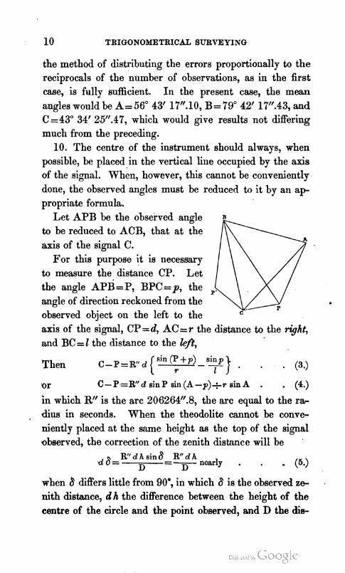
10. The centre of the instrument should always, when possible, be placed in the vertical line occupied by the axis of the signal. When, however, this cannot be conveniently done, the observed angles must be reduced to it by an a p
-
propriate formula, Let APB be the observed angle
to be reduced to ACB, that at the axis of the signal C.
For this purpose it is necessary to measure the distance CP. Let the angle APB=P, BPC=p, the p,
angle of direction reckoned from the observed object on the left to the @ axis of the signal, CP =d, AC=r the distance to the right, and BC=l the distance to the left,
Then
'or C-P.=W d s inP sin (A -p) ,) i~ sin A . P a )
in which R" is the arc 206264".8, the arc equal to the r* , dius in seconds. When the theodolite cannot be conve-
niently placed at the same height as the top of the signal observed, the correction of the zenith distance will be '
d6= Rfl d h ain 6 ~c. d h nmrly
D =- D (5.)
when 8 differs little from 90°, in which 6 is the observed z e nith distance, d h the difference between the height of the centre of the circle and the point observed, and D the d i e

AND LEVELLINO. 11
tance. I n thesi formula the signs of the trigonometrical quantities must be carefully attended to.
EXAMPLE 1. Let P =65" 41' 6.5, p= 181" 35' 13.5, d= 155 feet, r= 33329.8 feet, and Z= 74707.5 feet ; required the reduction of P to C by formula (3) ?
LogR" . . 5.314425 Logd . . 2.190332 --
+7.504757 . -7.604767 P +p=2470 16'2W'sin-9.964896 p=181° 35'13.5 sin-8.442422 a . c . l o g r . . + 5.477167 a . c . log I . + 5.126636
-- 1st time - 88Y.8 log -2.946820 2d time + 11".8 log + 1.073816' 2dtime + 11.8 ,
- 873 .O= - 14' 33.0 P = . . 6 5 4 1 6 .6 -- C = . . 65 26 33 .5 corrected.
Ex. 2. From Allington Knoll the staff on Tenterden Steeple had a depression of 3' 5lU.0, or 8=90" 3' 5Y.0, and the top of the staff was 3.1 feet higher than the axis of the instrument when a t that station. On Tenterden Steeple the ground at Allington Knoll was depressed 3' 3P.0, or 8'=90" 3' 3P.0, and the axis of the instrument when a t this station was 5.5 feet above the ground; required the corrections of the observed zenith distances, the lineal distance between the stations being 61777.5 feet?
Log R" . . 6.314425 . . 6.314425 a . c . l o g D . 5.209169 . . 5.209169 d h= + 3.1 feet log + 0.491362 d h = - 5.5 feet log-0.740363
d 8= + 1W1.35 log+ 1.014956 d 8'= - 18.36 log - 1.263967
the corrections of the zenith distances sufficiently acourate by the more simple formula, since 6 and 8' are so near 90".
When these corrections are to be applied to the angles between the verticals of two given points, they may be corn- bined follows : -
TMGONOMETRICAL SURVEYING 1 Log R" . . 5.314425 dh+dhf= +3.1-5.5= -2.4 feet log -0.380211 a . c . l o g D . . 6.209169
the same as d 8 + d &= + 1OU.35 - 1.8O.36 -- - 8".01. I
(11.) In measuring horizontal or vertical angles in refer- I
ence to terrestrial objects, if the atmosphere is not sufficiently %
clear, it is difficult to intersect the signals with the neces- sary accuracy. In this case an instrument called a heli* trope is generally used to reflect the sun's image in the di- rection of the observer. I have found the usual reflecting horizon of coloured glass set in a frame, turning on a hori- zontal and on a vertical axis to obtain any requisite incli- nation, very convenient for this purpose. The proper direc- tion of the sun's image may be given by a circular piece of polished block tin or brass, with a circular hole of three or four inches in diameter in it, stuck in the groove of the
I
usual offset-staff, through which hole the station of the ob- server must be seen, while, by reflection from the glass, the ring of the perforated disk must be illuminated.
12. To conduct a general series of observations, either on land or at sea, for the purposes of surveying, &c. the follow- ing general remarks will be found useful.
lo, To record the state of the barometer and thermo- meter, three or four times d a y , more especially when making observations.
2", To take altitudes carefully on objects useful for time, &c. from three to six hours distant from the meridian.
3", To find the error of chronometer as often as possible, to be able-to compute the correct time of transit of the sun, stars, &c. by it, for latitude by circum-meridian altitudes, &c.
4", To observe objects having equal altitudes nearly, to

*AND LEVELLING. . 1 3
the north and south of the zenith, to destroy the effects of ,
errors in the instruments employed, such bias of axis, errors of division, glasses, artificial horizon, kc. ; the same method should be pursued for the accurate determination of time by selecting objects to the east and west.
5", In the case of marine surveys, to observe on land as often as safe and convenienh, with the best instruments for time, latitude aaul longitude, by lunars, moon-culminating stars, occultations, &c.
6", To choose a station somewhat elevated, free from woods, jungle, &c. so that, with ordinary care, surprise by the natives will be impossible or difficult.
7", To take magnetic bearings of well-defined and con- spicuous objects whenever practicable, from points well de- termined in latitude and longitude. If convenient, angular observations with the theodolite and other instruments would be better.
8", To repeat your observations if possible at least three times, to guard against mistakes, which, even with the greatest care and experience, will sometimes happen. To make one or more assistants take observations along with you, and to receive their reports without communicati~lg your own. If there be such a difference as to indicate a decided fault somewhere, the observations ought to be re- peated till the cause of the discrepancy be removed. 9, To make such calculations only as may be absolutely
necessary to carry on a connected series of useful observa- tions.
lo0, To keep regular and clearly writtell note-books, on a systematic plan, in which every thing is recorded, so that any mathematician or astrdnomer may be enabled to deduce fair conclusions at any future period. These books must be all properly ruled, titled, and numbered, for future refer-

14 . TRIGONOMETRICAL SUBVEYING
ence. Marks and abbreviations should be all carefully re- corded and explained.
13. These general views being premised, it will now be necessary to enter into the practical details. I t is hardly possible, in these operations, to divest the formulm entirely of an algebraical character in some cases, though it will be done as often as possible, One of the processes in trigon* metrical surveying is the determination of the latitude. This operation is most simply performed by a meridian altitude or a zenith distance, and if a circumpolar star be selected, the result will be independent of the exact position of the star, because the latitude, in that case, is equal to half the sum of the altitudes of the star above and below the corrected for the effects of refraction by Table V. When a eenith sector like that belonging to the Board of Ordnance is used, the stars must be selected near the zenith, and con- sequently little error is to be feared from the effects of r e fraction, while the great power of its telescope, and the ge- neral accuracy of its construction, render a single observa- tion by it a close approximation to the truth. When, how- ever, the smaller classes of instruments are employed, it then becomes necessary to repeat the observations near the meridian, reducing those taken at a short distance, such as about ten or fifteen minutes, to what they would have been on it, from a knowledge of its distance from that circle in time, the approximate latitude and declination of the object observed. I n this way the results from smaller instruments become nearly equivalent to those of the greater, since as many observations may be taken by the former in one day as by the latter in ten.
ON FINDING THE LATITUDE.
14. The most easy and ready way of finding the latitude

. AND LEVELLING. 15
is by a meridian altitude of a celestial body whose declina- tion is known. Should the object have a sensible diameter, like-the sun or moon, the altitude or zenithdistance of the lower or upper limb, or, what is superior, both are alter- nately observed, and, by the application of several corree tions, that of the centre is obtaiiled.
When reflecting instruments, such as the sextant, repeat ing circle, &c. with an artificial horizon, are employed, the arc read off must, from the nature of the instruments, be halved before the corrections are applied. At sea, since the lower limb of the sun, moon, or the centre' of a star, is generally brought to the visible horizon, the dip from Table I. must be subtracted before the corrections from Table 11. &c, are taken. At land, a meridian altitude of the sun, moon, or a planet, must be corrected for refraction, parallax, and semidiameter, but not for dip, At sea, the same corrections are applied after the dip has been sub- tracted. All these may be found by the following tables and the Nautical Almanack. The refraction constitutes the whole correction of a fixed star at land. At sea, the dip must be previously subtracted.* If the instrument does not give the zenith distance, it nlay be found by taking its complement to 90°, denominated north or south, according as the observer is north or south of the object.
Now, if the zenith distance and declination be of the same name, their sum is the latitude; but if of contrary names, their dzference is the latitude, of the same name as the greater,
EXAMPLE 1. At Pladda Light, in longitude 20" 30' W., 20 feet above the level of the sea, on the 15th of August 1836, the follow-
* The method of applying all these corrections is given in the expla- nation of the tables, and illustrated by the following examples.
16 TRIGONOMETRICAL SURVEYING
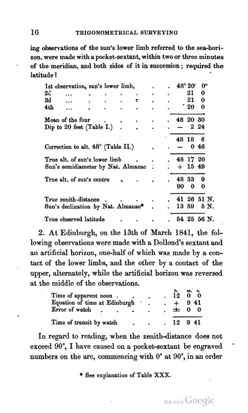
ing observations of the sun's lower limb referred to the sea-hori- zon, were made with a pocket-sextant, within two or three minutes of the meridian, and both sides of it insuccession ; required the latitude ?
1st observation, sun's lower limb, . 48'20' 0" 2 1 ... 2 1 0 3d ... < 2 1 0 4 t h .. . 2 0 0
Mean of the four . 48 2 0 3 0 Dip to 2 0 feet (Table -1.) : . - 2 2 4
48 18 6 Carrection to alt. 48' (Table 11.) . . - 0 4 6
- - - -
True alt. of sun's lower limb . . 48 17 2 0 Sun's semidiameter by Nat. Almanac : . + 15 49
True alt. of sun's centre . . 48 3 3 9 90 0 0
True zenith-distance . . 41 2 6 51 N. Sun's declination by Nat. Almanao* , , 13 6 9 6 N .
True observed latitude . . 54 25 56 N.
2. At Edinburgh, on the 13th of March 1841, the fol- lowing observations were made with a Dollond7s sextant and an artificial horizon, one-half of which was made by a con- tact of the lower limbs, and the other by a contact of the upper, alternately, while the artificial horizon was reversed at the middle of the observations.
h. m. s. Time of apparent noon . 1 2 0 0 Equation of time a t Edinburgh ' . . + 9 4 1 Error of watch . = t o 0
Time of transit by watch . . 1 2 9 41
In regard to reading, when the zenithdistance does not exceed 90°, I have caused on a pockehsextant be engraved - numbers on the arc, comniencing with 0" at 90°, in an order
* See explanation of Table XXX.

AND LEVELLING. 17
the reverse of that usually adopted, and likewise on the ver- nier, so that I read zeiiithdistances in place of altitudes, even with the sextant, in such cases as it may appear more convenient, or I may read alternately, in different series of observations, both ways, as a check upon each other, to avoid mistakes in the reading. In the present instance, how- ever, the zenithdistance, when doubled, exceeded the limits of the instrument, as with the artificial horizon must be the ca.se, and therefore double altitudes were necessarily taken.
Barometer 30.3 inches. Them~onzeter 53' Pahr.
Times of Observation. Double Altitudes. h. m.
1st observation . 11 58 i5 . . s"l4'2&1.1. 2d ... - 12 1 53 . . 62 59 0 u. 1. 3d ... . 12 7 12 . . 62 63 30 u. 1. 4th . . . . 12 9 58 . . 61 56 50 1.1. 5th ... . 12 15 16 . . 62 52 30 u. 1. 6th . . . . 12 19 20 . . 61 52 40 1. 1.
Means . . 12 8 42.3 . . 62 22 53.3 -- Long. W. . . + 1243.5,Half . 3 1 1 1 2 6 . 7 Error of watch . 0 0.0 . . 90 0 0.0
Gl-eenwich M. T. 12 21 25.8 Zenith-dist. 58 48 33.3 N.
The refraction must now be computed by Table V. : Zenith-distance observed 58" 48'.6, log 8 6 . 1.9832 Bmometer b=30in.3, log (Table VI.) . 0.0043 Thermometer r= 53', log (Table VII.) . 9.9999 Thermometer t = 53", log (Table VIII.) . 9.9973
Refraction . . r=96".5 log . 1.9847 Sun's parallax (Table XII.) = - 7 .4 - T - ~ = c o r . 89 .1= 0" 1' 29 .1 Mean zenith-distance , . 58 48 33 .3 N.
- Corrected zenith-distance . . . 58 50 2 .4 N.
I t is ilow necessary to apply the reduction of the differ- ent partic~~lar obserratioiis by Table XVII., to reduce each

18 TRIGONOMETRICAL SURVEYISG
to what it.would have'been had it been made precisely on the meridian, which is most concisely done by grouping the whole together. For this purpose let A be the required zenith-distance upon the meridian, and 6 that obtained as above, then, in order to reduce 6 to a, we have the follow- ing formula :-*
~ = 6 - 2 s i n ~ & t coal cosd cosec(2-d) +2sin4&t{cos2cosdcosec(l-d))acot(l-d) . (6.)
in which t is the time from the meridian either before or after transit, in mean solar time if the sun be observed, but in sidereal if a star, I the latitude, and d the declination, reckoned minus if of a contrary name to I . This distinction may be avoided by substituting the zenith-distance for d-1. I t is clear that 2 sin + t is the versine of t, and that 2 sin4a t is half the square of the former, which are designated V and v in the table. To express the reduction in seconds of arc, each of these must be multiplied by R", an arc equal to the radius in seconds. This is ~ccomplished by the lo- garithms for V and v at the termination of the table, which include also the,division of the sum of the versines by the number of observations, thus simplifying the operation con- siderably. The computation is performed in the following manner :-
Transit by watch
1st observation 2d ... 3d ... 4th . . . 5th . . . 6th .. .
* This formula is easily deduced from elementary irivestigations, but are restricted to practice hcre.
AND LEVELLING.
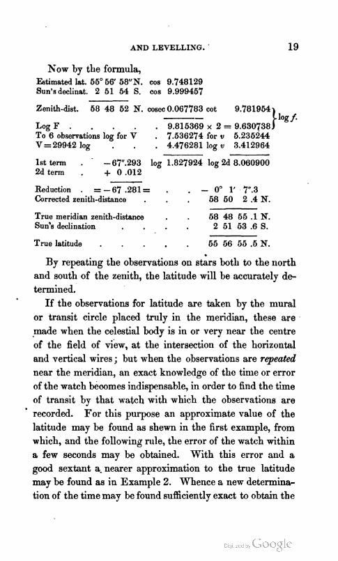
Xow by the formula, Estimated lat. 55O56' 58"N. cos 9.748129 Sun's declinat. 2 51 54 S. cos 9.999457
Zenith-dist. 58 48 52 N. cosec 0.067783 cot 9.781954 -- Log F . . 9.815369 x 2 = 9.630738 To 6 observations log for V . 7.536274 for v 5.235244 V=29942 log . . 4.476281 log v 3.412964
1st term . - 6Y.293 log 1.827924 log 2d 8.060900 2d term . + 0 .012 Reduction . = - 67 .281= . . - 0" 1' 7.3 Corrected zenith-distance . . 58 50 2 .4 N.
True meridian zenith-distance . . 58 48 55 .1 N. Sun's declination 2 51 53 .6 S.
True latitude . . 55 56 55 .5 N.
By repeating the observations on sgrs both to the north and south of the zenith, the latitude will be accurately de- termined.
If the observations for latitude are taken by the mural or transit circle placed truly in the meridian, these are made when the celestial body is in or very near the centre of the field of view, at the intersection of the horizontal and vertical wires ; but when the observations are repeated
near the meridian, an exact knowledge of the tinie or error of the watch beoomes indispensable, in order to find the time of transit by that watch with which the observations are
' recorded. For this purpose an approximate value of the latitude may be found as shewn in the first example, from which, and the following rule, the error of the watch within a few seconds may be obtained. With this error and a good sextant a- nearer approximation to the true latitude may be found as in Example 2. Whence a new determina- tion of the time may be found sufficiently exact to obtain the

20 TI1IGOWOMETRXCAL SURVEYING
latitude correctly, if a series of observations, a t nearly equal .distances from the meridian before and after transit, be em- ployed. The time may aIso be found by the method of equal altitudes, as shewn in the explanation of Table XVII I , whenever the weather is steady, especially in fine climates. I n our unsteady climate, absolute altitudes taken at nearly equal distances from the meridian east and west, and as close upon the prime verticd as possible, will prove very satisfactory, and then corresponding observations will not easily be lost.
TO FIND THE TIME.
15. Set down under each other the true altitude, poIar distance, and latitude. Find half the sum of these three, and the difference between that half sum and the altitude. Then to the log cosecant of the polar distance add the log secant of thc latitude, the log cosine of the half sum and the log sine of the difference, half the sum of these four logarithms will be the log sine of half the hour angle from the meridian. I n case of determining the time in this man- ner, it would be convenient to estimate it according to the astronomical method of reckoning, namely, from noon to noon throughout the twenty-four hours.. Hence in the fore- noon of the civil day, the hour angle thus found must be deducted from 24 hours, and the remainder will be the time past noon of the preceding day.
I n usiug a table of reduced versines, such as that given in my collection of mathenlatical and astronomical tables, the sun1 of the four logarithms mentioned above, rejecting tens in the index, will be the hour angle to be taken from the top of the page when the observation is made in the afternoou of tlie given day, but from the bottoin if in the forenoo~~,

A S D LEVEL LIAZ. 2 1
t o give the time past the preceding noon. This result will be the apparent solar time, to which the equation of time reduced, for the approximate time and longitude, to the cor- responding Greenwich mean time (G. M. T.), according to the directions given in the Nautical Almanac (N. A.), page 1 of each month, will give the mean solar time (M. T.) a t the place of observation.
If a star be the object, the horary angle must be taken from the top of the page if the star be west of the meridian, but from the bottom if east, to be alwccys reckoned west (W.). T o this meridian distance add the star's right ascension r o
duced to the given time, and the complement to 24 hours of &he sidereal time a t mean noon (S. T. &f. N.), reduced by Table XXVI. to the time and place of observation, the sum, rejecting 24 hours as often as possible, will be the mean solar time. If two stars be chosen, one to the east and another to the west, having the same altitudes nearly, any error from a faulty method of observing, or a bias in the instrument, will be avoided, and they should not have more than 30" of declination, because, from their slow mo- tion even on t l s prime vertical, stars having great declina- tions are in this case to be avoided.
The method of observing with a sextant having been al- ready shewn, that by the smaller classes of astronomical circles will now be exemplified. That which I generally nse is six inches in diameter, having three verniers, each reading lo", and the scale of its level, a fixed one, indicates 3" for each division, and reads from a central zero. The general formula to correct for the readings of the level, when applied to the zenithdistance, is

IoititaQ? correctly, if a wries of observations, at nearly equal dis~mres from the meridian before and after transit, be em- plo!.nl. The time may also be found by the method of eq~iid itltitadcs, na ahewn in the explanation of Table XVIII, wllei~crcr the weather is stcdy, especially in fine climam. In olir anste;~(ly climate, absolute altitudes taken a t nearly equal clistanccs from tlic meridian east and west, and as rlosc upon tlic prime vertic-a1 ns possible, will prove very sitisftwtory, and thcn correspondillg observations wilI not c:wily h- lost.
1'0 FIAT THE TIME.
15. &~t down uiicler each other the true altitude, polar dis~qnce. and latitnck. Find half the sum of these three, and the diffcreiicv between that half sum and the altitude- Thcu to the log cosecnnt of the p l a r distance add the 10," * a ~ t of thc latitude, the lo? cosine of the sum and tlhe ICY sine of the diffprencc, half the sum of these four E3;irirhnls will be the lo? sine d half the hour angle from zb mri iinn. In (YEW of determining the ti~lle in this WT- ir w t d d he cwlrenicnt to =iim,lte i t according to the *qr+nf -cz id method of re&nninr, namd, from noon to n.-*~a & r \ ~ - ~ h v l r the tuentv-four hours. Hence in tbe f o e no-lz i t f Ar. c i d dm. the hour myle thus found must be df-3~(:~3 fr,:a~ 24 h \ n ~ , u~d the r e n d e r sill be the time
II:IIIL i~ &- ;.>-\iinc. thy- 1L * & ibf ~ 3 1 : ~ ~ 4 1 ~-q>r&irs m ~ b = Ehaf @ven in
"T " 'Le* (9: n ~ s i ? l t ~ : ~ ~ ~ c ~ l a:t.3 .uyfi>xcm& the . - '' k l - ~ < ; h I Illi':lI~Clllr\~ St,vTe- -fl tm
< -. -dL I~~~~ Ar- - -A? hh.qir frcm top
QY -A' ,..! . . 'c- ' D'T ii?? . >~c.nxi:.-,?l 1. x,~, ill -&-
tT -it' ?-- ', . . 1 :i:.T,- ' I F 5-..1~? i] :y ~ , ( , i ~ , - , ~ ~ l >: ill ftm,,~.

XSD 1,EVE ' LISf;. 2 1
80 Five the time par the preeetlir~g IIOOII. Tllix rt~nllt will be the appKent solar time, to which tl,c rrl~lntion of tirw? r d u e e d , for tbe approximate time and 1torlg-i t t l l { ! , tr, tlltr arr- r e ~ n d i q Greenvieh mean time (O. M. T.), ilwr,rrIir~g tr, * he &re*ons &&en in the Sautital Alme~lrrc (S. A,), Pa@- 1 of each month, rill $re the mean vrlar tilnc (M. 'J',) a t the place of obmation,
If a the n i j r r ~ tile horary a:l:,Ie m w t 1 ~ : tilk,!l,
from the b p of tbe pu;w if the -xar G r,:.r c.f r ~ l n rn,:ri,l;;aj, But from the ~ z # ; * z if %L V, dmyr rw:knf,r:,l rr:at ( \V,),
- I - - ? TO "LJ ~ G - w *L+LG-+:~ :*i ~ r 2 * i , b r 3 nzl,k r,,,. . , &QC*~ t43 * &ken Eke- 2--,: c.-.+ c;,rr:.s:'.T:i';.t t,, ? # jl,,ri,-,, ,,f
the Gekral t i . u -L;;L. 2-1 -.. G - T. 51. 5, ,,.(I, jc4!,l I,:, , ,
T* n m 3; L++ LX ,*i ;,ic+ ,,:,,,~.,,:;.i,,~, lb: . . ==% 2-4 t.2; .:& ** 7 ,,,, ,,,$> f#; t},,;
- , -* ~ k 2 Ii rv.: isi-* -c I : - +-- r ,r rl, ::,I. r . : , , , ~
4 =o&er 2 , -> W - - L LL7:-&- -- *;5;:-,> - <, ;. + ., ;.,,* r 4 2 ,+; , . . . 2 9
a F r :LI.:- xtLju.. i .[ ,., e+E;:.G* ,,? % l,!&* ;,., the + .
- > r-- 3- L-14,kL C.8: ;,-.,-Y &.. , . . I ; . , : ;,,,,: i.,: ,.-. - - . tbaJl 13, - ,:f :t-*a;xt ,L ~+.;.:<'ie- :: r,: ;*2-:.. ,; ,.;* :;,<-
me~- a ilr ZPW -+T.,~?L._ +>iir ;:: --~;; >-..%; 2 ~ ; ; .,:.-
t lm3ar~ m &:*4 ,s7* - i- ,,:,..:-
= h r ! . . i i - - .v.::;t,.: ;;&. - - .P:.-, %.-
mil~ &qpJ- -A . 7' - =.p -a::*. .-- ;.2-r> ; x - 3 :-,n,-,t; ,+- v.
. 2 t + r y , A n ; - . I- . - . .,L. v ' . , " l , .x,.:.**
Q & & c ~ ~ & -n : i...-.~ s'~..t*-~*-. LL - . - . , , ..? - • ,- Y- '
r*z I+'- :mi _;,A Y.:~.,. .; ,.- .. - . % , : :s-' r , , , .-- f , ;,! ..?
. A . , , I , -..-. : . . -.- -. - . - - @mI ft>m& 2, . ,,- .,-- - . - , > - - 4,. . . .- ,- ~ h a *hi 3 3 ZIP 2-5, :. -,: :.. , , * - a . . - -

in which 1 is the resulting effect, e the sum of the readings a t the eye-end of the telescope, o the sum of those a t the object-end, a" the value of one division of the scale of the level, and n the number of observations.
In making a"=2" the preceding formula becomes
e-o I = - n :
by the scale of my circle. I n all cases care must be taken of the sign, according to
the rules of algebra. The signs must be changed when the instrumeilt shews altitudes. There are three parallel hori- zontal wires in the focus of the telescope, a t each of which the contact of the sun's limb may be observed. I generally observe the contact of the upper limb only at all the three when the sun is ascending, and then, on reversing the circle, the lower limb. I reverse this order when descending, tak- ing care of the apparent change of position, by an astro- nomical telescope, which shews objects inverted, that is, I observe the apparent lower limb first when the object is ascending, the apparent upper when descending, consequent ly the contacts are observed a t nearly the same altitude, and have the same refraction.
EXAMPLES.-~. On the 11th of August 1836, at Lamlash, in the Island of Arran, in latitude, by estimation, 55" 31' 5 6 N., longi- tude 20" 3 2 9 . , the following observations on the sun were made to determine the time. The assistant-watch, by which the ob- servations were made, was 28"ast of the chronometer, while the barometer stood at 30 inches, and Fahrenheit's thermometer at 50".
N O T E . - ~ the following observations the scale of the level read to 3 at Lam- lssh, and formula (7) wea employed to find I , the effects of the level ; but at Inchkeith it red to P, and formula (8) was employed. See pages 23 and 31.

AND LEVELLING.
Times by Watch, A. M. Ver. Z. D.
h. m b 9 1 49 A
B C
9 7 7 A B C
9 13 52 A B C
9 17 46 A
Mean . 9 10 8.5 B Watch fast - 9 43.5 C
Long. + 20 32.0 W.
E. G. M. T. 9 20 57.0, 1 =
Level. + - e o
8.5 21.5
53 27 42.0 r = + 1 18.7 a = - 0 6.7
True zenith-distance 53 28 54.0 90
True altitude A . . 3631 6 Polar distance . . 74 45 9 Latitude . . . . . 55 31 56
Sum . . . . . . 16648 11
Half H . . . . , . Difference H - A =
Equation of time . . Mean time . . . .
Mean time Time by watch + 12h =
Watch fast of M. T. . Watch fast of chronometer
83 24 5.5 cos 9.060360 46 52 59.5 sin . 9.863300 20 55 23.7 v. s. 9.186451 + 4 54.3
21 0 18.0
Chronometer fast . 9 22.5
On the evening of the same day, by a watch 10' slow of

24 TRIGONOMETRICAL SURVEYING
the same chronometer, and which was 3@ d a y , the following observations were made on a Aquilre.
Times by Watch. V. 2. D. Level. + - e o
1. 1"6?6:0 A 4 ° 7 9 $ b 22 10 B 9 20 C 9 40
2. 10 25 50 A 47 3 10 15 16 B 3 10 C 3 30
3. 1033 0 A 47 6 20 18 13.5 B 5 50 C 6 20
4. 10 39 50 A 4 7 5 0 12 19.0 - - Mean . , 10 29 12.5 B 5 10 67 58.5 Watch fast - 9 12.5 C 5 10 58.5 Long. . . + 20 32.0 W. -
47 G 2.5 8.5 G. M. T. . 10 40 32 I+. + 3.2 3 -- --
47 6 5.7 8)25.5 r + 1 2.8 - -- i- 3.2
Corrected zenith-distmce=47 7 8.5 N.
To find the mean time of transit by Tables XXVI. and XXVII., we have, by the Nautical Almanac, the
h. m. Sidereal time at Greenwich mean noon, #= 9 19 52:09 Reduction for long. 20m 32' W. (Table XXVI.) + 3.37
Sidereal time at Lamlash M. N. . 9 19 58.46 Star's right ascension . s=19 42 49.27
Difference, or s - u . Reduction to s - a (Table XXVII.) - Mean time of transit . Error of watch, fast . Time of transit by watch
h. m. 8.
Transit by watch . 10 30 21 m. a.
1st observation . 10 18 10, t = 12 11 2d ... . 10 25 50;t,= 4 31 3d ... . 10 33 0, t,= 2 39 4th . . . . 10 39 50, t 3 = 9 29

AND LEVELLING. 25
m. S. v. v For Rate, t =12 11 . 14126 . 1995 M.So.to sid.T. log +0.0023'75 t , = 4 31 . 1942 . 38 Daily Rate, t,= 2 39 . 668 . 5 Gaining 38 cor. . - 30 t,= 9 29 . 8560 . 733 --
- - Log for rate . + 0.002345 Bums, 25296 2771
Latitude . . 55' 3 i Q ~ N . cos 9.752772 Declination . 8 96 30 N. cos 9.995269
Zenith-dist. 8=47 5 26 cosec 0.135233 cot 9.968280
LogF . , 9.883274 x 2 =9.766548 Log V' for 4 . . 7.712365 logv, =5.411335 Vz25296 log . . 4.403052 logv, = 3.442636 Log for rate . 0.002345 log .
-- 8.588799 1st term- 100.240 log . 2.001036 2d term + 0 .039
100. 201 = -0" 1' 40.20 Corrected zenith-distance . . 47 7 8 .50
True meridian zenith-distance . 47 5 28 .30 N. Star's declination . 8 26 29 .95 N. --- True latitude, . . 55 31 68 .25 N.
I n this manner the observations may be repeated a sufficient number of times to ensure, from a mean of the whole, the requisite accuracy.
When the observations on stars are continued for a length of time, the logs of F and f remain nearly constant for the same star, and consequently these may be computed for such a number of stars as may be selected for observation. Indeed, special tables may be drawn up to every ten seconds, and these may be interpolated to every second in t, as was done by myself for a Aquilac, when I observed at Inchkeith, from which tlie reduction to the meridian may be made at sight. For this computation special tables ari sometimes given, but it may be easily effected by a table of reduced

26 TRIGONOMETRICAL SURVEYING
versines employed in the computation of time in last exam- ple, or by a table entitled Rising in the usual books of navi- gation.
Let F" = 2 R COB I cos d cosec 6 and . (9.)
f = 2 R (cos I cos d cosec a)* cot 6 . . (10.)
be computed for the given star. For a Aquilac, at Inclikeith, in latitude 56" 2' N., in
August 1840, when the star's declination was 8" 27' 7'' x., will be found.
LogF"= . . . . 6.489706 log f . 6.324769 For t= lbm log R. V. S. 7.029602 x 2 = 4.069204
1st term= - 330".60 log 2.619307 9.383973 2d term = + 0 .24
Red. = - 330 -36
Continuing this process for every 10n of t, the reduction may easily be found for single secolids by interpolation, which renders this method very easy ; and then the smaller classes of circles become in effect nearly equal to the larger, on account of the facility with which observations may be very numerously repeated.
16. In mean latitudes, such as in Britain, observations on the pole-star are very advantageous and convenient for the determination of both latitudes and azimuths a t the same time, which may be computed by the following for- mula :-
1. sin u =costtanp 2. sinh =cosucos 6secp 3. .1 =h*u 4. sin r =sin t sin p 5. tan m=tanrsech, or 6. tan m=sinttanpsech
nearly, and more simply than by (4) and (5) combined.

AND LEVELLING. 27
In these formul~, t is the sidereal time after transit, p the star's polar distance, h the latitude of the foot of the per- pendicular arc from the star upon the meridian, and 6 the zenith distance. Also 1 is the true latitude, in determining which u is minus in the first and fourth quadrants of t, and plus in the second and third. In like manner r is the per- pendicular from the star upon the meridian, and m the azi- muth.
17. If the latitude be previously well known, the azimuth may be found by Napier's Analogies, or from formulie or rules derived from them. For this purpose let c be the complement of the latitude, and p the polar'distance.
1 . tan 4 ( m + e ) = c o t + tcos + ( c c u p ) s e c + (c+p) , 2. tan & ( m - e) = cot & t sin + ( c c u p ) cosec 3 ( c + p ) . '
Hence 3 ( m + e) - + (m - e) = e, the azimuth of the pole-star from the meridian referred to the horizon. Or let d be the declination of Polaris, and 1 the latitude of the place of ob- servation,
3. t a n + ( m + e ) = c o t + t c o s + ( d c u l ) c o s e c + ( d + l ) , 4 . t a n & ( m - e ) = c o t & t s i n ~ ( d c u l ) s e c + ( d + I ) . ,
Since d and 1 remain constant during a series of observa- tions made in one day, while t varies, the logs of the two last factors are constant, and this renders the computation of an azimuth by the pole-star remarkably easy.
18. In many cases of nautical survejjng, the true bearing of any well-defined object at a considerable distance, and on, or nearly on, the same level with the eye of the observer, is required to be determined with a reflecting instrument. To perform this operation, bring the image of the sun to the object, and make its nearest limb accurately to to~lch the object, while at the same time with another instrument let the sun's altitude be taken. Correct the observed distance

28 TRIGONOMETRICAL SURVEYING
for index-error, if necessary, and add the sun's semidiame- ter ; the result will be the apparent distance of the sun's centre from the object. In like manner correct the sun's altitude for index-error, dip, and semidiameter, the result will be the sun's apparent altitude. Now, to compute the azimuthal augle between the sun and the object, there will be formed, when the object is on the same level with the eye, a quadrantal spherical triangle H Z 0, of which the sides are the zenith dii- tance ZH= 90°, the sun's zenith d i s tance ZO, and the ol~lique observed distance HQ ; to find the angle Z at
El the zenith, which is the difference be-
0; tween the bearings of the object and the sun. Compute the sun's true azimuth from the altitude in the usual manner, take the sum or difference of these, according to circumstances, as indicated by their relative positions with respect to the meridian, and the true bearing of the object will be deter- mined. I f the bearing of the same object be taken with the azimuth compass, the variatioil of the compass will likewise be obtained. To determine the true bearing in this manner, it must be remarked that the sun's vertical motion should be as great as possible, or his'position ought to be near the prime vertical, and that the object to which the sun is referred should be about 90" from the point of the horizon to which the sun is vertical. When this is im- possible, the object should be chosen so that the angle which the observed arc or distance makes with the horizon, may not by estimation exceed 45". When the object is elevated above the level of the eye, it is necessary to observe its alti- tude, and compute the angle at the zenith from the three sides of an oblique angled spherical triangle formed by the observed distance, and the zenith distances of the sun and

AND LEVELLING. 29
the object whose azimuth is required; and this is in fact the first part of the method of reducing, by spherical trigo- nometry, the apparent distance to the true in lunar obser- vations, that is, from the two apparent altitudes and appa- rent distance to find the angle at the zenith.
The azimuth of a point or signal, by means of the sun or a star, may be found readily when the time is accurately known. In this case there are given the polar distance and the hour angle, or that contained at the pole, to deter- mine the angle at the zenith by the Analogies of Napier.
If the sun be the object, the angle at the pole is the com- plement of the time to 12" in the forenoon, bnt the apprt- rent time itself, if in the afternoon. If a star be observed, the angle at the pole is equal to the sidereal time minus the right ascension of the star, or equal to the apparent time plus the right ascension of the sun, minus the right ascen- sion of the star. The polar angle is minus when the star is east of the meridian, plus when west.
When extreme accuracy is required in determining the azimuth of a signal, the observations of the angular distance, by the reflecting circle or by Borda's repeating circle, be- tween the star and the signal should be made at the same instant with the zenith-distance of the star and the signal, if convenient, though that of the latter may be made at any time either preceding or following the observations, since, with the exceptioil of refraction, it remains stationary. These distances are the apparent distances as affected by parallax and refraction. If the zenith-distance of the star cannot l~c! convenieutly observed at the same time when the angu- lar distance between the star and signal are taken, it may be calculated by spherical trigonometry, as will be after- wards shewn, taking care to apply the effects of refraction

e
30 TRIGONOMETRICAL SUI~VEYIXG
and parallax to find the apparent zenithdistance with a
contrary sign to that used in finding the true. When the azimuth is found by observations on the pole-
star, or similar methods, the horizontal circle must be read at the'same time with the vertical, in order to compare the azimuth of the star with a referring lamp, and from this, at any convenient opportunity, other conspicuous points se- lected as stations in the general purvey.
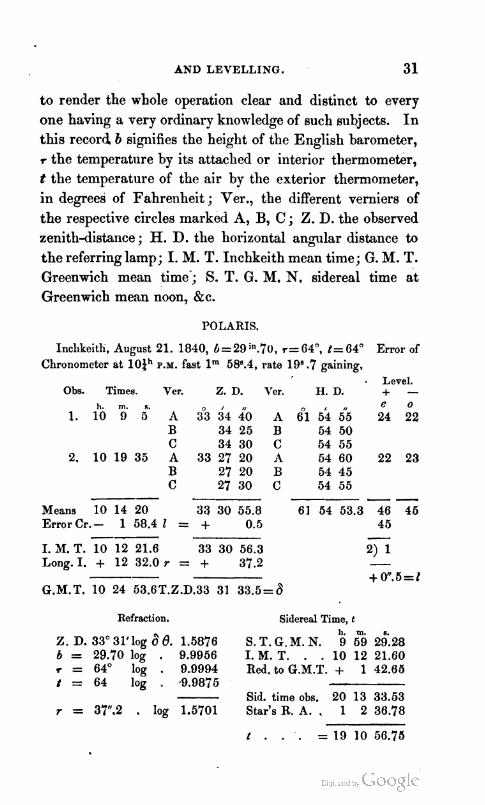
19. I shall now proceed to illustrate these rules and for- mula by practical applications. Having determined the error and rate of my chronometer, as previously exempli- fied, the following observations were made at Inchkeith Lighthouse, to determine the latitude and direction of the meridian by the pole-star. For this purpose I resided on the island a few days, during which I made several ob- servations on the heights in the vicinity of Edinburgh, as well as some on the latitude by the sun and a Aquilae, for which a special table was drawn up in the manner al- ready explained, by which the reduction to the meridian for the distance t was made by inspection. I chiefly trusted those made on the 21st of August upon the pole-star, which I continued to observe from about 10 o'clock in the even- ing to 1 o'clock next morning. During this period I com- pleted eight series of double observations,reversing the circle each time, or sixteen single observations, comprehending forty-eight readings of the verniers on each circle, accom- panied by the times of observations, and the readings of the level. The circles used were six inches in diameter, hav- ing eac'h three verniers reading to lo", and a level whose divisions each indicate 2". Having made these preliminary remarks, so that every thing relative to my operations may ' be fully understood, I shall record the first series of obser- vations, and perform the computations at full length, so as
AND LEVELLING. 3 1
to render the whole operation clear and distinct to every one having a very ordinary knowledge of such subjects. In this record b signifies the height of the English barometer, r the temperature by its attached or interior thermometer, t the temperature of the air by the exterior thermometer, in degrees of Fahrenheit ; Ver., the different verniers of the respective circles marked A, B, C ; Z. D. the observed zenith-distance; H. D. the horizontal angular distance to the referring lamp; I. M. T. Inchkeith mean time; G. M. T. Greenwich mean time'; S. T. G. M. N. sidereal time at Greenwich mean noon, &c.
POLARIS.
Inchkeith, August 21. 1840, 6=2gin.70, r= 64', t= 64" Error of Chronometer at l O a h P.M. fast lm 58".4, rate 19Y.7 gaining,
- Level. Obs. Times. Ver. Z. D. Vcr. H. D. + -
-- Means 10 14 20 33 30 55.8 Error Cr.- 1 58.4 1 = + 0.5 -- I. Jf. T. 10 12 21.6 33 30 56.3 Long. I. + 12 32.0 r = + 37.2 --
G.M.T. 10 24 53.6T.Z.D.33 31 33.5=6
Refraction. Sidereal Time, t 11. m.
z . ~ . 3 3 ~ 3 i ~ i 0 ~ a e . 1.6876 S.T.G.M.N. 9 592t .28 b = 29.70 log . 0.9956 I. M. T. . . 10 12 21.60 r = 64" log . 0.9994 Red. to G.M.T. + 1 42.65 t = 64 log . 9.0875
Sid. time obs. 20 13 33.53 r = 37.2 . log 1.5701 Star'sR.A. . 1 2 36.78
r . . . = 19 10 56.75
32 TRIGONOMETRICAL SURVEYING
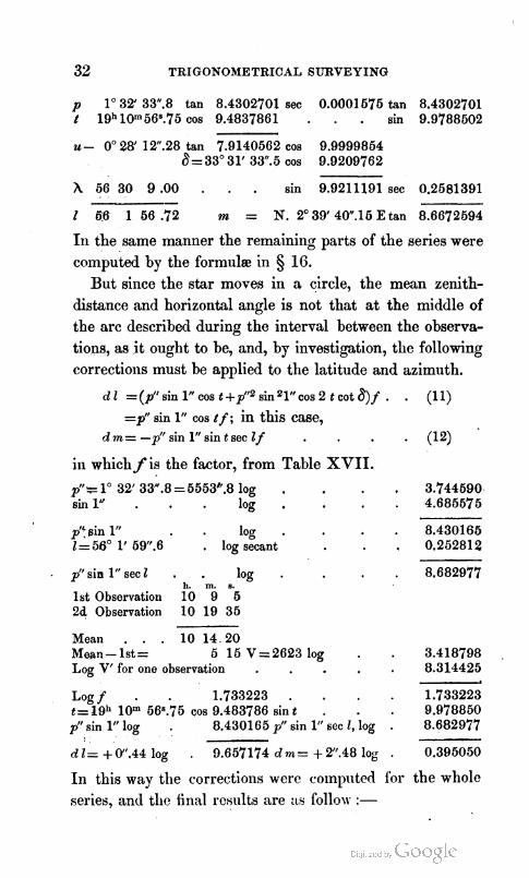
p lo 32' 33".8 tan 8.4302701 sec 0.0001 575 tan 8.4302701 t 19h10m568.75 cos 9.4837861 . . . sin 9.9788502
u- 0" 28' 12.28 tan 7.9140562 cos 9.9999854 a= 33" 31' 33.5 cos 9.9209762
h 56 30 9.00 . . . sin 9.9211191sec 0.2581391 - 2 66 1 66 .72 m = N. 2" 39' 4W.15 E tan 8.6672594
In the same manner the remaining parts of the series were computed by the formulse in § 16.
But since the star moves in a circle, the mean zenith- distance and horizontal angle is not that a t the middle of the arc described during tlie interval between the observa- tions, as it ought to be, and, by investigation, the following corrections must be applied to the latitude and azimuth.
d 2 = (p" sin 1" cos t +pU2 sin 21" cos 2 t cot 8) f . . (1 1) =pff sin 1" cos t f ; in this case,
d m = -pf' sin 1'' sin t sec Z f . (I2)
in which f is the factor, from Table XVII. lo 32' 33".8 =5563".8 log . . 3.744590
sin 1" . log . . 4.685575
p'i $in 1" . log . . 8.430165 1 = 56" 1' 6W.6 . log secant , 0.252812
pf'sin1"sec2 . . log . h, m.
1st Observation 10 9 ''6 24 Observation 10 19 35
Mean . . . 10 14.20 Mean - 1st = 5 15V=26Q3log . Log V' for one observation . Logf . 1.733223 . t=2gh 10" 5G8.75 cos 9.483786 sin t . p" sin 1" log . 8.430165 p" sin 1" sec 1, log
d l = + W.44 log , 0.657174 d m = + 2".48 log
I11 this way the corrections were computed for the whole series, an11 tlie final restilts are ;LS follo\v :-

LVD LEVELLING. 33
No.
1' 0 1 1,
dl' 1 , o , ,, Suc~essive )I valuea 56 1 56.72 +0.44=56 1 57.16 . . 56 1 57.16 N
2 1.14+0.33= 2 1.47 . . 1 59.31 2 2.04 +0.69= 2 2.73 . . 2 0.44 2 2.00 + 0.74= 2 2.74 . . 2 1.03 1 56.95 +0.30= 1 57.25 . . 2 0.26 1 58.30 +0.21= 1 58.51 . . 1 69.98 1 59.70+ 0.29= 1 59.99 . . 2 0.12 2 0.10+0.49= 2 0.59 . . 2 0.06 ,
Reduction to centre of tower for 25 feet - 0.24
True latitude . . 56 1 59.82 N
Azimuth of Light.
Mean azimuth . . N 64 34 35.64 E Reduction to centre of tower . - 35.70
Azimuth at centre of tower . . N 64 33 59.94 E Angle to Observatory . 134 9 7.30
Observatory bears from lighthouse . 198 43 7.24 . 180 0 0.00
Observatory bean from Inchkeith . S 18 43 7.24 W Convergence of the meridians d' . - 2 21.50
Inchkeith bears from Observatory . N 18 40 45.74 E
The method of computing d' will be subsequently given. The ~r i~ inometr i ca l Survey station is S. 25" 27' W.,
distant 6.855 feet from the centre of the dome or pillar, therefore,

34 TBIGONOMETRICAL SURVEY IKG
0 l r ,
To the bearing of Inchkeith above . . N 18 40 45.74 E Add reduction + 6.74 - Inchkeith bears from Trigonomet. Survey station N 18 40 52.48 E By Trigonometrical Survey . 18 40 53.50
Mean . 18 40 52.99
,20. ~ a v i n g now shewn the method of preparing the ob- served horizontal angles for computation, of fixing the lati- tude of any selected point, and the bearing of another from it, I shall now give a few rules and formulae for deducing from these; and an extended triangulation, the latitude, lon- gitude, and azimuth of the principal points of the series,- reserving the computation of heights to a succeeding part of this essay.
I n deducing latitudes, longitudes, azimuths, and heights geodetically, it is necessary to be enabled to convert readily any distance measured in feet on the earth's surface into arcs; and hence the radius of curvature of the measured arc, in any given position on the terrestrial spheroid, is re- quired by the principles of the conic sections.
Now, the radius of curvature is to an arc R", equal to the radius in seconds, as the distance in the same measure with the radius of curvature is to the corresponding arc in seconds. Let A4 be the required arc in secoiids, correspond- ing to A, any measured arc on the earth's surface in feet, to which r is the radius of curvature,
Wherefore, if 31 be the factor to convert a cnrvilineal dis- tance on the meridian into seconds of arc; P that on the perpendicular to it; and 0 that on any oblique arc, making an angle a with the meridian ; then, if a denote the radius

ASD LEVELLISG. 35
of the equator, b the polar sernioxis, e the eccentricity, and ,
I the latitude ;
R" s R" '3
M = - (a2 cos 21 + b2 sin "I)'=- (1 - c2 sin 22)y . . ad bL a (1-2) (14)
R" f R" 4 P=-(a2cos21+b2sin21) =- (1-e2sin") . . . . . (16)
aY a
1 - e2 (1 - cos 21 COB 2a) O = M cosaa+P s i n % a P
1-2 . . . (16.)
From these fo~mulz Tables XIX., XX., and XXI. have been computed, the coefficient for terrestrial refraction n, in the two last, having been taken equal to 0.08 or &, of the intercepted arc, which is a sufficient approximation to the truth in ordinary atmospheric circumstances.
21. Previously to the determination of heights trigono- metrically, the curvilineal distance, 0r its chord at the level of the sea, ought to be augmented for the height of the lower station, since the radii from the centre through their summits diverge proportionally to that height. This cor- rection may be obtained from the following formula, or the results derived from it arranged in a table. Let K be the chord of the augmented arc A at the height h, derived from the arc a at the level of the sea, then
M h M a 2 Log K=log a+--- = l ~ ~ a + r n h - ~ a ~ . p 24 p2 (17.)
From this formula Table XXIV. was computed. The num- ber S is the difference of the log secant of half the angle v between the verticals and log p a2, which contributes to greater accuracy in considerable heights. I shall now give the necessary formulae and rules to find latitudes, longitudes, and heights geodetically.

Exphnation of Syinbola, with their Values.
A =the measured arc in feet on the surface of the Terrestrial Spheroid. W = a n arc equal to the radius in seconds, . log 5.3144251
a = t h e i d i u s of the equator in feet, . . log 7.3106165 b =the polar semiaxis in feet, . . log 7.3191664
k-q11=0.0815816, log 3.81 15818 a
I=* e2 + & e4 + &c. = 8in= elliptically. . log 3.5228787 f = a e = 1706900 feet . log 6.2322083 c=a-b=ar=69742 feet, . log 4.8434944 I = the given latitude farthest from the equator.
I'= the required latitude nearest the equator. A=the latitude of the foot of the perpendicular from the required
point, upon the meridian passing through the given point. z = the given azinruth. $=the required azimuth.
A l= the difference of latitude. ~ p = t h e difference of longitude. A z= the difference of azimuth or convergence of the meridians passing
through the given and required points.
A R Making - =d, we shall have, from. an investigation a
that cannot be conveniently given here,
(1.) ~ ~ = - ~ " ( 1 + 2 ~ - 3 ~ S i n ~ ~ ) ~ 0 ~ ~ + a " ~ ~ S i n 1 " ~ ~ n ~ 6 i n ~ ~ (18) (2.) A p = a" (1 - E sin 21) sin z sec $-afa sin 1" sin z COB z tan E secl (19) (3.) A z= a" (1 - E sin '1) sin z tan 1' + a2 4 sin 1" sin z cos z . . (20)
These are the principal formulae generally required. In addition to these, that for determining an oblique arc may be added, O
4 . C c O = a " ( 1 - e s i n 2 1 + 2 1 ~ ~ s 2 1 ~ o ~ 2 a ) . . . . . (21)
Log sin 1"=4.685675, log sin lN=4.384545
Introducing the values of M, P, and 0, of which the lo- garithms are given in Tables XIX., XX., and XXI., ac- cording to the directions given along with them, making first r" equal to the reduction of h to 2, derived from the last part of -formula (la), given in Tables XXII. and XXII I .

AND LEVELLING. 37
( 4 . ) . ~ 1 = - A M c o s z + r " = A M c o s i n - 1 / ~ . . . ( 5 . ) a p = AP sin z sec 1' ZAP sin m sec Z' . . .
(22) (23)
(6 . ) A z= AP sin + ( 1 + 1') sec 4 (1-1') . . . . . (24)
I n north latitudes, the azimuth z is generally reckoned from the south towards the west or east, aud is the supple- ment of m, or that reckoned from the north, iu the appli- cation of which attention must be paid to the signs. Iu-
.deed, in some operations, the azimuth is reckoned from the east mestwax-ds round the whole circle, in accordance with which the arguments to Tables XIX., XX., and XXI. have been so given.
PRACTICAL RULES.
22. To illustrate the method of employing these formula3 and tables in calculation, let P be the north pole iu this ill- stance, E a point in the equator, B a poirit of which the latitude and longi- tude are known, T another place whose bearing and distance from B ape given, and from these the latitude and lon- gitude of T and the azimuth of B from x
T, are required. Also, let PBE be the meridian passing through B, PTF 7 I .
the meridian passing through T, PBT the azimuth denoted by a in the for- mulae, or m' or z' in the tables, BT
E the distance or curvilineal arc a in feet, of which the chord is k, T h a ! perpendicular from T, the required point upon the meridian pissing through the given point B, the distance from the, foot of which to the equator, measured by E h, is the lati? tude of h ; 2' the latitude of the place nearest the equatq, I that of the more distant, and T 2 the parallel of latitude

38 TRIGONOMETRICAL SURVEYING
passing through T, making E 1 the latitude of T, or that required. The very small arc h I, called the reduction of h to 1 in Tables XXII . and XXIII., must always be sub- tracted from h to give 1'.
If this small arc exceeds the limits of the tables, i t may be computed. For this purpose, it may be observed that ifpN be the perpendicular arc, then pN=AP sin z, the argument to find r" from the tables. But, independent of the tables,
r"=AQ2 s h 'Z 3. sin 1" tan Z=P"~,+ sin 1" tan 1 . . . (25)
the formula from which the tables were constructed, and may supply their place in cases beyond their limits.
I t must likewise be observed that B h is a small arc of the meridian to be added to the given latitude in proceeding to- wards the pole, or subtracted when receding from it, to give the latitude of the foot of the perpendicular h, the argu- ment for taking the log P from the tables. The argument to obtain log M is half the sum of the latitudes approxi- mately, or 4 (1 + lr), to be derived from a provisory calcule tion, in order to get the mean latitude between the given stations. The number of minutes to be added to the smaller latitude l', or bubtracted from the greater 1, to get (1+ r), may be computed by the following rule.
To the constant log 5.914630, add the log of the meri- diandistance in feet, the sum will be the log of half the difference of latitude in minutes, or Q (1-Ir), to be added to 1', or subtracted from 1, to give & (1 + lr), the middle latitude sufficiently near the truth for taking log M from the tables.
1. By a provisory calculation, such as that just given, or by a~epetition of the more accurate method now to be shewn, if thought necessary, find the middle latitude, or & (I+ 1').
2. To the logarithm of the curvilineal distance, or arc a, adtl the log cosine of the azimuth, or nr, and the log M from
AND LEVELLING. 39
Table XeIX., answering to the mean latitude, or 4 ( t+ 1'), the sum will be the logarithm of an arc of the meridian in seconds mu, to be added to the latitude 1' if approaching the pole, but subtracted from 1 if receding from it, the sum or difference will give A, the latitude of the foot of the per- pendicular upon the given meridian from the point in that required.
3. To the log of a add the log sine rn, the azimuth, the log P answering to h, the sum will be the log p", the per- pendicular arc in seconds.
4. To the constant log 4.384545 (the log &sin 1") add log tan A and twice the logpN7 the sum will be log r", the reduction of h to 1 always subtractive. This may be also taken from Tables XXII . or XXIII. , if within the limits of the.tables. I t may be observed, that four times r", an- swering to $p" will be the reduction to p" nearly, which will extend the table, and the results will not differ much from the truth. This, at least, will be a check to calcula- tion.
5. To the log tangent pN add the log secant l', the sum will be the log tangent ap, the difference of longitude, which, properly applied to the longitude of the place of ob- servation, will give the longitude of the point required.
6. To log tangent ap add log sine & (1 + 1') and .the log secant 4 (1-1'), the sum will be the log tangent A z, the con- vergence of the meridians of the given and required points, which, added to the azimuth rn', at the latitude nearest the equator, will give m, or rather z, the azimuth at the latitude farthest from it, and vice versa.
7. To the log 0, answering to the middle latitude and given azimuth a, from Table XIX., add the log of the given distance a, the sum will be the log of the intercepted arc in seconds, which measures tlw angle between the verticals of

40 - TRIGONOMETRICAL SURVEYING
the given points. If the log 0 be taken from Table XX., the result will be angles of the verticals diminished by the effect of refraction, taken at 0.08, of the intercepted arc. The log 0 from able XXI. is the log of 4 p (1 + np, em- ployed in the computation of heights by the depression of the horizon of the sea, the mean value of n being 0.08 as before. By these rules the position of any number of points may be fixed; but in practice a difTerent arrangement is frequently followed.
Suppose parallel to the meridi'an of Edinburgh and to its perpendicular to be drawn through each station, we have the bearings and distances of the other stations from such parallels, calculated by means of a rightangled plane tri- angle, of which the distance or hypotenuse, and the bear- ings or one angle, are given, to find the other two sides. Thus, let k be the distance, m the azimuth, and r the sphe- rical excess, we have strictly a triangle deviating slightly from a rightangled triangle, when the spherical excess is applied, but in all ordinary mses of practice the latter may be safely omitted. Now, if x be the distance from the pa- rallel to the ~erpendicular on the meridian in feet, y the distance from the parallel to the meridian also in feet, in- troducing r, we have
Omitting a, as is the general practice, and
This may be permitted, because each determination of a point is an independent operation, and is not affected by an accumulation of errors.
23. 1 shall now give a general outline of the method of conducting the survey of a county or of an island on the pre- ceding principles. I n this case, it is necessary to determine

AND LEVELLING. 4 1
the latitude, longitude, and direction of the meridian of any convenient point A, as has already been shewn, with refer- ence to a side of one or more of the triangles, such as b AB, or cAC, &c. It mill then be necessary to throw a series of judiciously chosen triangles over the surface of the island and adjacent islets as may be near its coasts, such as ABC, CBG, kc., so as to embrace the chief features of the whole island. These points must next be referred to the principal meridian by means of perpendiculars let fall fr?m each point upon it, thus forming the abscissae + X, - X, kc. to the
eouth and north of the point A, and ordinates parallel to the perpendicular to it +Y, -Y, &c. to the west and east of the same meridian. These are represented by Aa, Ab, &c. and Da, Bb, &c, by drawing temporary parallels to +X, -X, &c. +Y, -Y, &c. throughout the whole corn- pass of the survey; those absciss~ to the south d A being conditionally reckoned positive, those to the north negative; while those ordinates to the east of A are considered negative,

42 TRIGONOMETRICAL SURVEYING . - and those to the west positive. If a distance as AB cannot be deduced from an adjacent survey with sufficient precision, then a fundamental base in some convenient situation must be measured with great care, and connected with some of the sides trigonometrically, from which the sides of the whole series of triangles must be deduced by calculation, as formerly shewn. 'This is, for the sake of distinction, called the primary triangulation, in which the sides of the triangles extend from about 30 to.50, or even occasionally to 100 miles. These larger triangles are next broken down into a smaller class, called the secondary, whose sides are limited to about 10 or 15 miles, in which the angles may be measured with somewhat inferior instruments. The inter- mediate points are then filled in by the five-inch theodo- lite, the surveying compass, and th6 chain, which may be called the tertiary triangulation, and co~lcluding process.
24. In a similar manner may a survey of the adjacent coasts of a strait, firth, or river, be completed, and the bearings and distances of corresponding points on opposite sides be laid down, whether they be.visible from.each other or not. This may be readily done in various ways, one of which is, to run two parallels or two meridians of known distance from each other, as may be most convenient under given circumstances, and, by finding the positio~i of each station on its own meridian, that is, its distalice o ~ i tbe me- ridian from a give11 point in it, and the perpendicular from it upon that meridian, then these will afford the means, by the solution of a triangle, to find the bearings and distances of all or any of them, in such directions as it may be thought necessary or convenient to lay down soundings, leading marks, dangers, Bc. ; by which means the nautical surveyor will be enabled to complete his chart in a satisfactory man- ner.

AND LEVELLING. 43
Let NS, N'S' be the two conventionally chosen meri- dians by one or more surveyors, whose operations embrace the opposite shores of a river or strait, where it is possible and safe to have the necessary piles and staffs erected on shore, then the perpendicular distance H Q being found by
observations taken on purpose, the points A, C, E, G ; H, I, L, 0, P, may be referred to their respective meri- dians KS, K'S', as in the preceding figure. By the solu- tion of the rightdngled plane triangle HQA, right-angled at Q having AQ, QH given, the angles QAH, AHQ may be found, together with the side AH. Hence the angle I H A may be found, consequently with the sides IH, HA, and the contained angle IHA, the side I A may be found whether the point A be visible from H and I or not. R'ow the angle CAQ being known, and IAQ having been found by computation, the angle CAI becomes known. Whence, with the given sides 114, AC, and the contained angle IAC, the side IC may be determined.

44 TRIGONOMETRICAL SURVEYING
It is clear that this method, combined with others easily deduced, may be followed through the whole series ; from which the form and contour of the shores and distances on which soundings, dangers, &c. should be placed or laid down on a chart are readily inferred. Should the survey be carried on in a foreign country, or barbarous shores, where, from danger, the necessary marks cannot be safely erected on shore, the masts of lighters, boats, and barges, properly secured, may be used as ignals, especially if they have polished frusta of cones of zinc-plates, or sheets of block-tin fixed to the masbhead. ,These may have the greater diameter about nine inches, the less six, and the height twelve, or in these proportions nearly, greater or less according to the distance. These will reflect the sun's image readily to the observer, even in thick weather, whence the angles will be obtained in an easy and satisfactory man- ner, when the observer and the objects are in a proper po- sition, the time of which must be estimated and carefully watched.
If the lines of reference assumed are parallels of latitude, they will continue equidistant, but if meridians, they will converge towards the pole, and diverge towards the equator, and the distance between them will vary as the iadius of the parallel. In nice operations of considerable extent, this variation cannot be neglected, though in those of smaller magnitude, it will be so inconsiderable, as, in ordinary cir- cumstances, to be of little consequence. To take this into account when thought necessary, let R be the radius of cur- vature of any parallel whose latitude is l,
a cos 1 R = = a cos l(1 - n sin21) . . . (26) (1 - e" in "I)+
Whence, by computing for the parallels of 1 and l', the distance at 1 may be reduced to that at 1'.

AND LEVELLING. 46
25. If, however, a parallel to the primary meridian be assumed, the operation will be more simple, as it will be unnecessary to compute the convergence in feet, or their distance at different latitudes, while the latitudes, longitudes, and azimuths may still be readily found by the preceding rules, and this is the method generally adopted.
Let X X be the meridian passing through the Observe tory of Edinburgh A, YY a perpeildicular to it, x x, x 'd, &c. parallels to XX, passing through the stations, B Ben- cleugh, C Bencampsie, D Benlomond, E Goatfell, E Cairn Aird in Islay, and K Kellylaw in Fife. Hence there are formed the triangles ABC,BCD,DCE, and EFD, which are treated as already directed, pages 5, 6, kc. Having deter- mined the bearing of Bencleugh, or angle BAX = a, and the distance AB = k, there may be found A a = - x and B a= + y, and so on to the last triangle A F d; from which the absciss Ad= + x, and F d= +y are obtained from a combination of all the intermediate triangles computed in a similar manner, and the results are stated in a table.
Though the signs in the following examples are those employed by many engineers, especially on the Continent, yet in my opinion it would probably be better to make those

46 TRIGONOMETRICAL SURVEYING
6f x positive when they increase the latitude, and negative when they diminish it. The lines x x , &c. being all paral- lel to XX, are therefore, it must be recollected, not meri- dians. The latter meet at the poles, and consequently are inclined to one another at certain angles. Thus the meri- dian n s is inclined to X X at an angle nFz"" of 2" 34' 17", which is called the convergence of the meridians, A z, and varies with the latitudes and difference of longitude as com- puted by formula (6), page 37, and recorded for each s b tion in the table, if thought necessary. It must be properly applied to the bearings, such as BAa, so as to get the bear- ing of A from B, called technically, especially by marine surveyors, the back bearing.
Having established these general principles, we shall now illustrate the whole by practical examples. By our opera,- tions at Inchkeith, in latitude 56" 1' 59".82 N., longitude 12" 3 2 T . , we have found that Edinburgh Observatory bears S 18" 43' Y.24 W., distant 302'72 feet, it is therefore required to find the latitude and longitude of Edinburgh Ob- servatory, and thence the position of the Trigonometrical Survey Station, in order to connect these triangles with it, so that the results in our examples may be comparable with those in the survey. I t must be observed that Cairn Aird ,
was not observed from Goatfell, and that I merely computed the bearing and distance from the approximate latitudes and longitudes by Ivory's formula, as given in my Mathematical
.and Astronomical Tables. Consequently these results are to be considered as approximative only.*
* From these circumstances, though the position is given in the figure, the numerical results are not stated in the following table.
s

AND LEVELLING. 47
Inchkeith Light, latitude, I . , 5 ° 6 i 6 ~ Edinburgh Observatory, latitude, I' . . 56 57 16 N
Sum, or I + F . . 111 59 16 -
Half, or (1 + r) . . 55 59 38
Difference, or 1- F . - 4 44 Half, or + ( I - Z') . 2 22
Edinburgh Observatory, longitude . ~ ‘ O & W Inchkeith Light, longitude , . 3 7 5 6 W
Difference, or ~p . 2 50
These being points pretty well known, their latitudes and longitudes will therefore turn out, by a geodetical computa- tion, the same nearly as stated above.
This operation is performed by the formulz given at page 37, or the subsequent practical rules, by the aid of the Tables XIX., XX., XXI., XXII., and XXIII . ; for the method of using which tables, their explmation must be consulted. 4 ( I + $)= 55" 5Y 38" logM=7.9937224 gives log P=7.9928141
,z= 18 43 7 .24cos 9.9763985 sine . 9.5068992 A=30272 feet log 4.4810411 . . 4.4810411
ml' = - 0" 4' 42.591og 2.451 16209 = lt35".610g1.9802544 I = 56 1 59 .82
$= 65 57 17.20secant .. . 0.2519306 -- a p = 0 2 50.68 log . . 2.2321850 L'= 3 7 56 .OO 4 (1 + 1') = 55" 5Y 3 8 sine 9.9185430 L = 3 10 46 .68 A % = 0" 2' 2lW.49 log 2.1507280
z= 18 43 7 .24
* This correction, 1.1,-may be readily taken from TableXXIII. in general. It may also be computed by the formula (26), psge 38.
. 3.96051 . 4.38455 Tan A . . . . . . . . 0.17028
r" = (Yf.033 . . . . . . . 8.51534
which is alwaya emall, when the difference of longitndc is not .great.

48 TRIGONOMETRICAL SURVEYING
Hence l', the latitude of Edinburgh Observatory, is 55" 57' 17".20 N., longitude L=3" 10' 46".68 W., and the bearing of Inchkeith light from Edinburgh Observatory, or m', is N. 18" 40' 45".75 E., agreeing with the result in pages 33,34. Hence, as is stated there, from the Trigono- metrical Survey Station, near the pillar in the Observatory,
Inchkeith Light bears . . N. 1; 46 55.00 E. Angle, Inchkeith, Calton, Bencleugh, 73 16 29.28
BeLleugh bears from Calton Station N. 54 35 36.28 W. Angle, Bencleugh, Calton, Bencampsie, 28 43 26.47
Bencampsie bears from Calton Station N. 83 79 2.75 W.
Bencleugh bears from Calton , . N. 5 i 36 3i.28 W. Benlomond, Calton, Bencleugh, . 18 36 57.00
Benlomond bears from Calton . . N. 73 12 33.28 W. Also, by observation, Kellie Law bears
from Calton Station . . N. 3? 2; 2.00 E.
With the distances in feet from the Calton to these different points, their latitudes and 16ngitudes may be found in the manner just shewn.
From the ~ri~onoxhetrical Survey Station on the Calton Hill, then, there will be obtained
1. Kellie Law bears N. $7 2/3 2.00 E. distant 135083.5 feet. 2. Bencleugh bears N. 54 35 36.28 W. distant 146334.6 feet. 3. Bencampsie bears N. 83 19 2.75 W. distant 196909.0 feet. 4. Benlomond bears N. 73 12 33.28 W. distant 308307.6 feet.
Though the preceding data are sufficient to fix the posi- tions of the respective points recorded, yet we shall treat the whole in a systematic manner as a small arc of a paral- lel across the country, in order to exemplify the method of conducting such operations, and deducing the results s u e cessively from each other.
Commencing at the Trigonornetrial Survey Station on

AXD LEVELLISG. 49
the Calton Hill, fixed by our previous deductions, we shall now determine the positioils of the places recorded above, beginning with that of Kellie Law.
1. Constant logarithm, P. 38 . . 5.914630 a = N . 37' 23' E. cosine . . 9.900144 A= 135083.5 feet . . 5.130602
* ( l - - r ) • + 0" 8'.8N. m'log 0.945376 ,? . . + 55 57.3 N.
This prelimi~iary step is only an approximation to the mid- dle latitude, or * (1 + l'), in order to get the argument to take the logarithm of the factor M from Table XIX. for converting feet on the surface of the earth illto seconds of arc, to determine 1 accurately when P is known.
& ( l + 11)= 60s 6 Q logM=7.9937149 X gives log P, 7.9928071 m= 37 23 4 cos . 9.9001374 sine . . 9.7833033 A= 135083.5 log . 5.1306020 . . . 5.1306020
m"= + 6 fi.92 log . 3 . 0 2 4 4 5 4 3 ~ " ~ 1/3 26.7 log 2.9067124 Z'= 55 57 17.20
1= 56 14 52.76 secant . I
. 0.2652382 " , I ,
Ap= - 0 21 11.95 E. log . . 3.1619506 L = 3 10 46.68 W. d ( l + lt)=56" 6' Y.98 sin 9.9190916
Boaring of Calton, or z= S. 37 43 9.15 W. from KellieLaw.
* L o g p U x 2 = . . -6.81342 Log f sin 1"= . . 4.38455
- ~ ~ 6 6 " 15' tm . . 0.17511
r"2 -2".36 log . 0.37308 . ..
I)

50 TBIGONOUETRICAL SUBVEYISO
2. &netant logarithm . . 5.91463 a= 54" 30' cosine . . 9.76289 A = 146334.6 log . . 5.16535 I
)(1-A?+ 0" 7.0 . log 0.84287 r 65 57.3 I
f ( l + 2')=56 4 .3 logM=7.9937170 . . log P 7.9928086 1 m=64 35 36.28 cos . 9.7629597 . . sine 9.9111902 Az146334.6 log . 6.1653471 . . 5.1653471
ni'= + 6 1; 55.65 log . 2.9220238 jd'= 1b $h log 3.0693459 l'= 55 5'7 17.20 I
l= 66 11 7.87 secant . . 0.2545430
ap=+6 $5 6.0910~ . . 3.3238889 I L'= 3 10 46.68 d. ( I + 2') =5G0 4' 12'!.63 . sine 9.9189323
L= 3 45 64.77 AZ= d 29 9:13 . log 3.2428212 ' m= 64 36 36.28
I
Bearing of Calton, or z= S. 55 4 45.41 E. froni Bencleugh.
I n the same manner may the computations of the positions of the other points be performed.
We shall, however, here determine the position of Ben- campsie from Bencleugh, and then that of Benlomond from Bencampsie, whence, in a similar manner, may any number of points be fiied in succession.
Angle, Calton, Bencleugh, Bencampsie . . 165 $3 kj.68 Calton bears from Bencleugh . . S. 65 4 45.41 E.
Bencampsie from Bencleugh bears S. 60 28 58.27 W. distant 98240.3 feet.
3. Constant logarithni . . 5.91463 = 50' 29' cosine . 9.80366
A = 98240.3 feet log . . 4.99229 - 1 - ) - Y.1S.log . . 0.71058
1=56 11.1 N.
4 ( l + r )= 66 6 .o log M 7.9937150 log P . 7.9928126
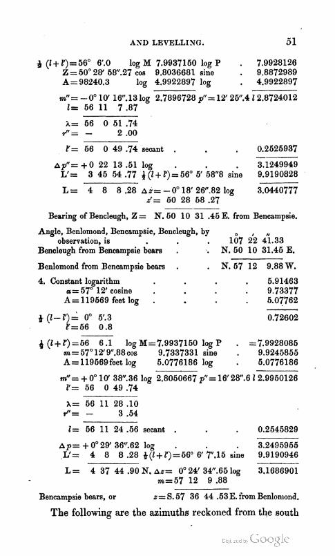
4 (1 + 1')= 56" V.0 log M 7.9937150 log P . 7.9928126 Z = 50" 28' 5W.27 cos 9.8036682 sine . 9.8872989 A = 98240.3 log 4.9922897 log . 4.9922897
mt'= -0" 10' 16".13 log 2.7896728 pff=12' 2V.4 12.8724012 l= 56 11 7 .87
l'= 56 0 49 .74 secant . . 0.2525937
~ p " = + 0 22 13 .51 log . . 3.1249949 L'= 3 45 54 .77 4 (I + Z')= 56" 6' 58"8 sine 9.9190828 - . .
L = 4 8 8 .28 A%= - 0" 18' 26".82 log 3.0440777 d= 50 28 58 .27 --
Bearing of Bencleugh, Z = N. 50 10 31 .45 E. from Bencampsie.
Angle, Benlomond, Bencampsie, Bencleugh, by observation, is . 167 2'2 2 . 3 3
Bencleugh from Bencampsie bears . '. N. 50 10 31.45 E.
Benlomond from Bencampsie bears . . N. 57 12 9.88 W.
4. Constant logarithm . 5.91463 a= 5'7' 12' cosine . . 9.73377
A=119569feetlog . . 5.07762
+ (1-r)= oO 5f.3 0.72602 Z1=56 0.8
4 (1 + Z') =56 6.1 log M=7.9937150 log P . ~7.9928085 m= 57°12f9".88 cos 9.7337331 sine . 9.9245855 A= 119669feet log 5.0776186 log . 5.0776186
rnl'= + 0" 10' 38O.36 log 2.8050667 p"= 16'28".6 12.9950126 11= 56 0 49 .74
h= 56 11 28 .10 #'= - 3 .54
I = 56 11 24 .56 secant . . 0.2545829
Ap=+O029'36''.62log . . 3.2495955 L 4 8 8 .28 *(l+ l')=56" 6' 7.15 sine 9.9190946
L = 4 37 44 .90 N. A%= 0" 24' 34".65 log 3.1686901 m=57 12 9 .88
Bencampsie bears, or z= S. 57 36 44 .53E. from Benlon~ond.
The following are the azimuths reckoned from the south

throughout the circle, and the latitudes and longitudes of the preceding stations in pairs, the longitude west' being marked + , east - .*
NAMES OF STATIOBB. Azimuth. - 1 1. Calton St.ation, 2. Kellie Law, .
2y7 i 3 i .00 37 43 9.15
3. Calton Station, 4. Bencleugh, .
155 i 4 2g72 304 55 14.59
5. Bencleugh, . 6. Bencampsie, .
Lntitude. I Longitude. I
i8 ;8.27 230 10 31.45
7. Bencampsie, . 8. Benlomond, .
- -
In the preceding table, the azimuth opposite Calton sig- nifies that Kellie Law bears 217" 23' 4".00 from the south towards the west round the circle, and conversely from Kellie Law the Calton bears S. 37" 43' 9".15 W., and so on of the rest.
26. In some cases the eastings and westings, and north-
507 h 9.88 302 23 15.47
ings and sonthings, are put down, as already remarked, as co-ordinates, and from these the. latitudes, longitudes, and azimuths, are determined. This gives some advantages and some disadvantages, and therefore may or may not be practised at the option of computers. They are tabulated in the following manner, the azimuths being all referred to the meridian of Edinburgh.
* I n like manner latitudes north n ~ a y be marked + , south -.
No. - 1 2 3 4
Log x.
5.0307394 4.9BXG3 4.3601014 4.9496976
R
N. $7 h LOO E. N. 51 36 36.28 28nT N. 83 19 2.75 W. N. 73 12 3328 W.
x
-107334.5 - 847'82.6 - 22914.0
- 89063.0
Y
+ 82017.3 + 119271.7 + 1955713 + 295163.3
Log y.
4.9139033 5.07&73 5B13030 h4700623

AND LEVELLING. 5 3
From the coordinates in this table the positions may be fixed as before, and all referred to the same meridian. For a n exemplification of this, see my Mathematical Tables. To extend right-angled triangles in this manner by parallels t o the primary meridian, however, should not be carried too far. To avoid this, a new meridian may be assumed at the distance of every two or three degrees of longitude.
The method of measuring an arc of the meridian may be readily uude.rstood fro111 the figure page 41. Suppose the latitude of the point A to be accurately determined, and the azimuths of the sides of the triangle ABD in reference to the meridian XX', then by the perpendiculars Da, Bb, Cc, &c., the parts A a, a b, b c, &c., may be found, the sum of which will be the total arc Ah ; or by the intersections a, p, y, 6, &c., the portions A a, a p, p y, &c., may be found, from the sum of which arises A h, the whole arc. Now the latitude of the point h being likewise determined, and the azimuths of the sides h H, h F being also obtained as a v e rification of those derived from the other extremity a t A, the length of the whole arc A h in feet with its correspond- ing arc in the heavens, the difference of latitude, become known, from which the length of a degree a t the middle . latitude will be readily found by dividing the extent of the arc in feet by that of its corresponding arc in degrees.
I n measuring an arc of the meridian, if the perpendicular I h, fig., page 41, be small, the points I and h may be con- sidered as nearly on the same parallel of latitude ; but if it be somewhat considerable, A is not upon the same parallel with I, the difference between which is the smaliarc of the meridian h 1, fig., page 37, computed from the formula
~ " = p " ~ ,4 sin 1" tan E . P 7 )
in seconds of arc. This formula may be transformed into

54 TRIGONOMETRICAL SURVEYING
another, giving the reduction in feet instead of seconds, and it then becomes
when z and A are given, or when pv2 is given,
in which p is the reciprocal of M, readily obtained by using the arithmetical complement of log M in the computation, while pN2 is the square of the perpendicular arc in seconds, found by a previous part of the computation, and I the - l e titude.
Constant logarithm = log + sin 1" = 4.384545.
Since the point I is always farther from the equator than the point h, the foot of the perpendicular from it upon the meridian, this correction must be applied to reduce h to the same parallel as I, and must be added to the arc of the
meridian, when the point I is at the end nearest the equa- tor, but subtracted, as in this case, when it is farthest from it.
EXAMPLES-1. By the Trigonometrical Survey, volume ii. p. 56, giving an account of the measurement of an ai-c of the meridian between Dunnose and Clifton, the distance, I h, of the station at Clifton is 4770 feet from the meridian of Dunnose, XX', on an arc perpendicular to it, in the latitude of 53" 28' 30" N. nearly ; required the correction h I, fig., p. 37, of the meridian arc Ah, fig., p. 41, in feet?
Here, in reference to formula (28), 2 = 53' 28' 30, and . . A sin z = 4770 feet ;
Whence + sin 1". log . . 4.384645 Log Rf (Table XTX) to 1 = 53" 2V.5 . 7.993903 1 = 63" 28' 30" log tangent - . . 0.130395 Log A2 sin2 z= 2 log of 4770 feet . . 7.357036
I.= -0.7343 foot, log . . 9.865879

AND LEVELLING. 56
This reduction being required at the end of the arc farthest from the equator, must be subtracted from the arc between the pelpendiclllars, to reduce it to that between the pa- rallels.
From one computation, the distance between the per- ~endiculars, page 55 of Trig. Survey is 1036334.40 feet
By another, page 67, it is . . 1036333.90
Mean of these two . 1036334.16
But the zenith-sector was placed 6.5 feet south of the t h e e dolite station at Dunnose, and 3.5 feet south of the station
'
at Clifton, which increases the arc by 3 feet, their diffec- ence ; whence, by applying these corrections, we have
Mean value from the triangles . . 1036334.15 feet Correction for the positions of the zenith-sector . + 3.00 Reduction to the parallels , - 0.73
True length of the arc . . 1036336.42 feet
supposing the trigonometrical computations in the survey to have been accurately performed.
The length stated in the survey, in which this reduction is neglected, is 1036337 feet, that does not differ materially from the preceding result, on account of the smallness of the perpendicular arc, and for- that reason was probably omitted.
2. The same omission in the measurement of the French arc of the meridian between Montjouy and Formentera would have produced an error of 169.88 French toises,on account of the magnitude of the perpendicular arc from Formentera on the meridian of Paris, had it not been counteracted partly by an opposite error, arising from the insufficiency of a formula of Delambre, as there employed, which is given in the third volume of the Base du Syst2m Mdtriqm, page 4, illus- trated by a, numerical example, page 190, producing an

5 6 TRIGONOI+IETRICAL SURVEYING
error of 100.07 toises, with a contrary sign. The differ- ence of these two make on the whole an error of 69.81 toises in the results of the original commission, published in the Connaissance des Terns for 1810. This error was first detected by M. Puissant, and has been finally verified by a new commission lately appointed for that express purpose. This correction ought, therefore, hardly in any case to be neglected. M. Puissant, however, shews that Delambre's formula* is quite accurate when the convergence of the meridiank, c", is taken into account, or if, instead of z, the azimuth simply, (z+c") be employed. I t is certain that Delambre did, in some instances, understand the formula in this sense ; but it appears probable that he had not attended to it in some manuscript instructions communicated by him to the commission of 1808.
To avoid any difficulty from this cause, it may be recom- mended, in general, to trace the meridian arc through a continued series of triangles, so that the extremities of that arc may commence and terminate in the vertices of the first and last triangle, as nearly as may be convenient. If not, the small correction derived from this formula must not be neglected:
It would extend this paper too much to enter a t length into this subject, which may be seen more fully developed in the Introduction to my Mathematical Tables.
I n Marine Surveying, a table of meridional parts is ge- nerally required to one or two places of decimals, and in cases of great accuracy they shonld be used for a spheroid of about a& of compression. If the reduction of the lati- tude from Table XVI. be subtracted from the apparent or observed latitude, the meridional parts answering to the

AND LEVELLING. 5 7
remainder or geocentric latitude, will be those on the sph* roid. I generally, however, prefer the following form~lla, in which the first term gives the meridian parts on the sphere, and the remaining terms give the corrections to re- duce the meridian parts on the sphere to those on the sphe- roid of s&=j of compression. Let P =the meridian parts on the spheroid to I , the observed latitude, then
P=7915'.705 log (log tan (45O+ + I)-10) -22j.9182 sin 1 + W.0127 sin 3 1-&c. . (30)
Log 7915.705=3.8984896. log 22'.918=1.360181; and log w.0127 =2.10380.
EXAMPLE 1. Required the meridian parts to latitude 55" 30: both on the sphere and spheroid ?
1. Constant log . . 3.8984896 2. Constant log . -1.360181 45"+*1=72" 45' . 9.7058012 sin I= . . + 9.915994
1st term= +4020/.60 log 3.6042908 2dterm-18l.89 log- 1.276175 2d tern1 = - 18.89 3d term= + 0.00 3. Constant log . + 8.10380
Sin 3 1 , . +9.36818 P' . = 4001.71
3d term + 0.003 log + 7.47198
Hence the meridian parts for latitude 56" 30" are 4020t.60 (the first tern) on the sphere, and 4001.71 on the spheroid of -,b of compression.
Ex. 2. Required the meridian parts for latitude 56" 30' ?
Am. On the sphere . 4127.90 On the spheroid, or P = . . 4108.80
In this way the meridian parts may be computed to every degree and minute throughout the extent of the survey. Now, when the proper scale is chosen for a degree of lon- gitude, the differences of the meridian parts for each degree, &c., throughout the extent of the survey from the same
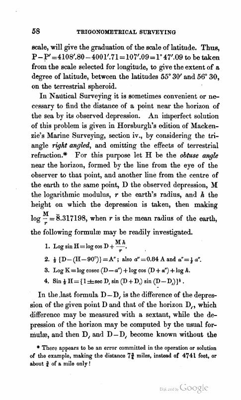
58 TRIGONOMETRICAL SURVEYING
scale, will give the graduation of the scale of latitude. Thus, P-P'=4108'.80-4001'.71=10'7'.09=1" 47'.09 to be taken from the scale selected for longitude, to give the extent of a degree of latitude, between the latitudes 55" 30' and 56" 30, on the terrestrial spheroid.
I11 Nautical Surveying it is sometimes convenient or ne- cessary to find the distance of a point near the horizon of the sea by its observed depression. An imperfect solution of this problem is given in Horsburgh's edition of Macken- zie's Marine Surveying, section iv., by considering the tri- angle right angled, and omitting the effects of terrestrial refraction.* For this purpose let H be the obtuse angle near the horizon, formed by the line from the eye of the observer to that point, and another line from the centre of the earth to the same point, D the observed depression, M the logarithmic modulus, r the earth's radius, and h the height on which the depression is taken, then making
M - log - = 8.31'1198, when r is the mean radius of the earth,
r
the following formula may be readily investigated.
2. 4 (D- (H- 90")) =A" ; also d1=0.84 A and up'= ; a". 3. Log K = log cosec (D - a") + log cos (D + a") +log h.
4. Sin 4 H=(l*sec D, sin (D + D,) sin (D-D,))i .
In the .last formula D - D, is the difference of the depres- sion of the given point D and that of the horizon D,, which difference may be measured with a sextant, while the de- pression of the horizon may be computed by the usual for- niuiz, and then D, and D - D, become known without the
* There appears to be an error committed in the operation or solution of the example, making the distance 76 miles, instead of 4741 feet, or about 3 of a n~i le only!

AND LEVELLING. 59
employment of an altitude-circle on shore, and in this case the upper sign must be used.
EXAMPLE. Let the observed depression of a given point from the top of Goatfell, in the island of Arran, D=2" 18' 8."4 by an astronomical circle, and the height h of the circle above the level of the sea 2861.5 feet; required K, the chord measuring the dis- tance of the point observed from the station on which the obser- vation was taken 1
Constant log . 87317198 h = 2861.5 feet, log 3.456694
Sum . 5.773792 Natural number 0.0000595 D= 2" 18' V.4 cosine . . 9.9996493
H= 92 5 52 .4 sine . . 9.9997088
D-a" =2" 12' 59".3 cosecant . . 1.4125687 D+aN=2 19 10.2 cosine . 9.9996440
h= 2861.6 feet, log . . 3.4565938
K=73927.6 feet, log . . 4.8688065
the first approximation, which, in moderate distances, will in general be sufficient.
For a second approximation, the following method may be employed, in which log K is that previously found.
5. Log d = C o n s t . log 7.617089 +log K.
6. Log at'= Const. log 6.8969'30 + log K.
Const. logs, 1 s t 7.617089, 2d . . 6.896930 L o g K . , 4.868806 . 4.868806 -- a"=% 6".1 log . 2.485895, a1'=68".3 log 1.765736
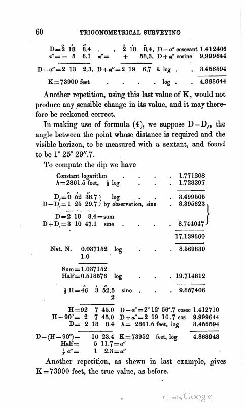
60 TRIGONOMETRICAL SURVEYING
0 I I1
D=2 18 8.4 . . i 8 6.4, D- a" cosecant 1.412406 a"= - 5 6.1 a"= + 58.3, D + a" cosine 9.999644
D-a"=2 13 2.3, D+a1'=2 19 6.7 h log . . 3.456594
K=73900 feet . log . . 4.868644
Another repetition, using this last value of K, would not produce any sensible change in its value, and it may there- fore be reckoned correct.
I n making use of formula (4), we suppose D-D,, the angle between the point whose distance is required and the visible horizon, to be measured with a sextant, and found to be lo 25" 29".7.
To compute the dip me have
Constant logarithm . h=2861.5 feet, log
I I/
~ , = " o 2 38.71 log D - D,= 1 25 29.7 by observation, --
D=2 18 8.4=sum D+D1=3 10 47.1 sine ,
Nat. N. 0.037152 log . 1 .o
. 1.771208
. 1.728297
. 3.499505 sine , 8.396623
. 8.74404'7
17.139660
. 8.569830
Sum = 1.037152 Half=0.518576 log . . 19.714812
0 I 11
& H z 4 6 3 62.5 sine . . 9.857406 2
H =92 7 45.0 D-a1'=2" 12' 5V.7 cosec 1.412710 H-90°= 2 7 45.0 D+aN=2 19 10.7 cos 9.999644
D= 2 18 8.4 h= 2861.6 feet, log 3.456594
D- (H- 90")- 10 23.4 K=73952 feet, log 4.868948 Half= 511.7=a" +af'= 1 2.3=a"
Another repetition, as shewn in last example, gives K = 73000 feet, the true value, as before.

AND LEVELLING. 6 1
The former method is recommended when the observer has a good altitude and azimnth circle ; the latter, when he has a sextant or reflecting circle only, as is frequently the case with nautical surveyors.,
27. Trigonometrical Levelling is an operation which g e nerally accompanies Trigonometrical Surveying, because the exact situation of a Gven point on the earth's surface is accurately fixed by the three coordinates, latitude, longitude, and elevation above the mean level of the sea. The triangle formed in a vertical plane above the earth's surface in this operation is called a hypsometrical triangle. It is formed b j the chord of the terrestrial arc comprised between the verticals of the two stations where the reciprocal zenith distances have been observed, by the straight line which joins the two points of observation and the difference of level d h. When reciprocal and simultaneous observations are made, that is, when observations are made from two different points on one another at the same time, the results are esteemed the most accurate, as the effects of refraction at the two places is determined by observation. In this case, let 6 be the observed zenithdistance at the one place, and 6' that at the other, less than the former, while C is the angle contained by two vertical lines drawn from the sur- face of the earth to its centre ; then the difference of alti- tude will bc found by the following formulac.
dh=Ksin&(d-a') s ec i (B-I fC) . (I)
= K tan 4 (8 - I ) very nearly. . PI But it frequently happens that reciprocal and s i m u l b
neous observations cannot be observed; then, in that case, if n be the coefficient of terrestrial refraction,
d h = K s e c & C c o t ( B + ( n - 0 . 5 ) C ) . (3)
= K cot (8 + (n - 0.5) C} very nearly. . (4)

62 TRIGONOMET~ICAL SURVEYING
The same thing may be done by the following formula, in which the first part is the solution of a right-angled plane triangle, and the second contains the effects of the curva- ture of the earth combined with the refraction.
in which p is the radius of curvature equal to the mean r+ 1
dius of the earth nearly, or exactly - = f sin l", in which f is g
the factor, from.Table XIX., to convert feet into seconds of arc.
To determine the height of the point of observation by the observed depression of the horizon of the sea,
dh=+g(1+n)2tan2(d-900) . PI in which 8-90" may be replaced by D, the observed de- pression of the horizon of the sea,
.dh=+g(1+n)ahn2D . (7) + R"
where 4 p = -, 8s before. . f
For many practical purposes the mean value of n=0.08 of the intercepted arc will be sufficient, and
dh=0.5832gtan2D . . . PI or, when the depression D does not exceed a few minutes,
d h=0.5832 g sin2 1" IY2 nearly . (9)
Constant log. of 0.5832 g sin2 IN== 6.457582.
The same value of n might be introduced into formula (4) and (5) , and the former would become
d h = K cot (8-0.42 C) (lo)
the latter becomes

AM) LEVELLING.
0.42 - and log-=8.302632. e
These mean coefficients are, however, combined properly in Tables XXI. and XXII., corresponding to formulac (4) and (9). By a paper in the Edinburgh New Philosophical Journal for April 1841, I have given the following formula to conlpute the value of n in given circumstances, and the computation may be readily performed by the aid of Table XI. and the auxiliary refraction tables.
a r Log mz= Constant logarithm 7.57877
This const. log. is combined with the factor 0.75-- ( 3 9
in Table XI., for the use of which see the explanation of the tables.
1. To exemplify these formuh, we find that at
Clermont Ferrand &' = . 803 38 G.37 Puy de DGme 8 . . 96 30 38.67
in. Also b1=28.839, i= 55.7 F. t'=405.14 F.
b ~ 2 5 . 3 8 3 , r = 51.1 F. t =48.92 F. The base K in English feet log . , 4.4875'708 To + (E+P)=45" 47' and a=84P0 log 0 7.9930870
C= j i145 . . log 2.4806578 6 - 1 = 12" 57 5.30
-- 4 (8-&'+ c ) = 6 31 3.87 secant . . 0.0028161
a(6-a)= 6 28 32.65 sine . . 9.0522416 K . . log . . 4.4875708 '
d A = 3488.42 feet log . . 3.5426284
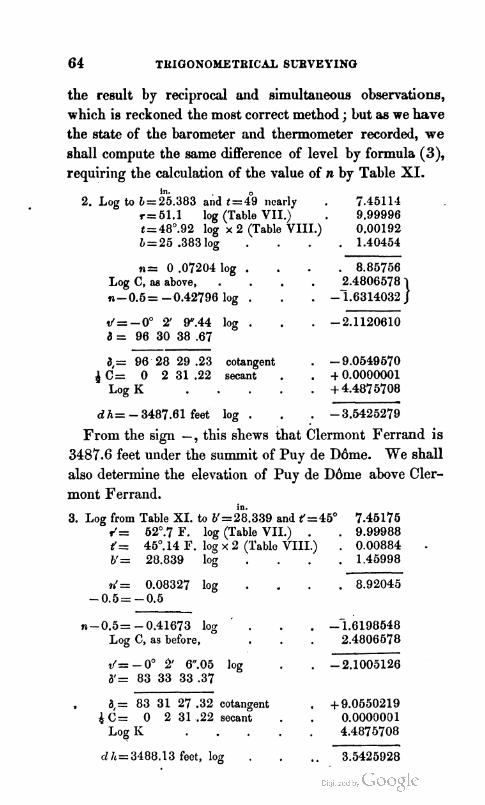
the result by reciprocal and simultaneous observations, which is reckoned the most correct method ; but as we have the state of the barometer and thermometer recorded, we shall compute the same difference of level by formula (3), requiring the calculation of the value of n by Table XI.
In. 2. Log to 1=25.383 and t=& nearly . 7.45114
r= 51.1 log (Table VII.) . 9.99996 t=48".92 log x 2 (Table VIII.) 0.00192 1 = 25 .383 log . . 1.40454
n= 0 .07204 log . . 8.85756 Log C, aa above, . - n- 0.5 = - 0.42796 log . . - 2.4806578 1.6314032 1 d= -0" 2' W.44 log . . -2.1120610 a = 96 30 38 .67 -- a,= 96' 28 29 .23 cotangent . -9.0549670
d C = 0 2 3 1 . 2 2 secant . . +0.0000001 Log K . +4.4875708
d h = - 3487.61 feet log . . -3.6425279
From the sign -, this shews that Clermont Ferrand is 3487.6 feet under the summit of Puy de DGme. We shall also determine the elevation of Puy de DBme above Cler- mont Ferrand.
in. 3. Log from Table XI. to b1=28.339 and 1=45' 7.45175
d = 62O.7 F. log (Table VII.) . . 9.99988 t'= 45O.14 I?. log x 2 (Table VIII.) . 0.00884 - b'= 28.839 log . . 1.45998
rr'= 0.08327 log . . 8.92045 - 0.5= -0.5
- n-0.5= - 0.41673 log . -1.6198648
Log C, as before, . 2.4806678
d= -0' 2/ 6.05 log , -2.1005126 6'= 83 33 33 .37
. 8,= 83 31 27 .32 cotangent . +9.0650219 $ C = 0 231.22secant . . 0.0000001
Log I< . 4.4875708
d1~=3481).13feet,log . .. 3.5425928

AND LEVELLING. 65
Agreeing almost exactly with the first solution by reciprocal and simultaneous observations, while, by the value of n com- puted from the formula, the results differ by about half a foot only,-a strong proof of the accuracy of the principle which I employed in its investigation.
4. To determine the coefficient of refraction by observe tion, we have r=n C, C being the intercepted arc, and n the effect of refraction, a part of that arc.
But r=a C-4 ( 8 + 8 ' - 180").
Introducing this into the preceding equation, and it be- comes by reduction,
Now at Puy de DGme. 8= Clermont Ferrand I=
0 50.41 log . 2 C=10 4.90 log . nz0.083336 log . - 0.5 -0.416664 log .
Log C; as before,
d=-oO !2' w.02 log . d = 96 30 38 .67
d,= 96 28 32 .65 cotangent -9.0550213 K . . log . . 4.4875708 d h 3488.13 feet log . - 3.5425921
Here the result is the same as before. As v' here foulld agrees almost exactly with that previously determined from
E

66 TRIGONOMETBICAL SURVEYING
the computed value of n, the computation need not be re- peated. In fact, the distance is too small for the refraction to produce a very marked effect, though this example has been selected by both Puissant and Biot to test their for- m u l ~ . From this, too, it appears that the refraction deter- mined by observation is not that at either point, but a mean between them.
I shall now proceed, from Inchkeith, to determine the heights of the former points (in the preceding part of this paper) above the sea.
6. At Inchkeith, in August 1840, I found the zenith dis- tance of the summit of the dome of Edinburgh Observatory to be 89" 40' 2P.45, at the distance of 30117 feet, bearing S., 18" 43' Y.24 W., when the barometer b stood at 29.675 in., and Fahrenheit's thermometer at 63O.8 ; what was the height of the summit of the Dome above the place of observation, and above the mean level of the sea 1
Log from Table XI . to b and t . . 7.44996 r= 63O.8 log from Table VII . . . 9.99941 t=63 .8 2 log from Table VIII . . . 9.97538 b=29.675 log . . 1.47239
n= 0.07892 log . . 8.89714 - 0.5
n-0.6= -0.42108 log . - 9.624364 Log 0 for lat. 56" and z=19" . . 7.993624 A=30117 feet, log . . 4.478812
d= -0" 2' P.97 log . - 2.096800 IS= 89 40 24.46
a,= 89 38 19.48 cotangent . + 7.799698 A=30117 feet, log . . 4.478812
d h= 189.89 feet, log . . 2.278510 h= 4.OO=height of circle above ground.
h'= 175.00 =height of ground ab.ove high-water. h".= 8.50 =half rise of tide.
H'= 377.39 feet.

AND LEVELLING. 67
H1=377.39 feet, the height of the summit of 4he dome above mean tide.
Station 26.90 feet under the dome.
H=350.49 feet, the height of the axis of the circle on the cy- lindrical stone south-west of the Observatory, from which I took the following observations on Bencleugh.
6. From this point the summit of Bencleugh was observed to have azenith-distance of 89" 22'4P.86, when the barometer stood at 29.68 in. and Fahrenheit's thermometer at 62", the middle latitude being 56" 4' 12'' N., bearing N. 64" 36' W., distant 146334.6 feet ; required the height of Bencleugh above the place of observation, and also above the mean level of the sea ?
To b = 29.68 and t = 62" log (Table XI.) 7.45022 r=62O log . 9.99948 t=62" . logx2 . . 9.97864 b = 29.68 log . 1.47246
n= 0.07956 log . 8.90070
- 0.5 - log A . n - 0.5= - 0.42044 log
Log 0 to 56" and 64O.6 . d=-oO1w 5".5710g . a= 89 22 41 .85
a,= 89 12 36.28cotangent . A = 146334.6 log .
rn h, from Table XXIV. S, from Table XXIV.
d h = 2017.65 feet, log . h = 350.49 =height of Calton Station.
H = 2368.14 =height of Bencleugh.
I n this manner the elevation of any number of points may be determined successively.
The difference of level may be found approximately with sufficient precision for many purposes by reciprocal zenith-

68 TRIGONOMETBICAL SURVEYING
distances, independent of triangulation. This method is not so accurate as the preceding, but will frequently be useful where tolerable accuracy only is necessary.
From a Gmple investigation, when n=0.08, it will be found that the sum of the refractions, or
where 6 and 8' are the apparent zenithdisbnces. If C be the true angle at the centre, and c the apparent,
in which r + r' is got from formula (14), and c= 6 + 8'- 180". If, however, n and n' be computed from the state of the
barometer and thermometer, as has been already shewn, then
This value of C will generally be more accurate than the preceding. The difference of level will then be computed by the following formula, dh=2gtan+Ctan+(B-8 )+2ptan2&Ctan2+(d-~ ) . (17)
in which the first term will generally be sufficient.
0 I 11 in. o 7. Let a=90 25 43.11, b=28.355, r=44.4, t=&.4 F.
1 = 8 9 54 41.22, b=29.339, 1 ~ 6 5 . 4 , t'=52.7 F. From these,
a+I-180°=c= 20 24.33 n = 0.08220 $ c = 4 4.87 n'=0.08195
C=c+ j c = 24 29.20 n+n1=0.16415 1.0
8-8= 31 1.89 +(a-C)= 1 5 3 0 . 9 4 1 - (n + n') = 0.83585
Log cfl=log 20' 2P.33 . . 3.08790 Log 1 - (n + n') = 0.83585 . . (~ubt . ) i.92113
C ~ 2 4 ' 2 8 . 1 3 . . log 3.16677
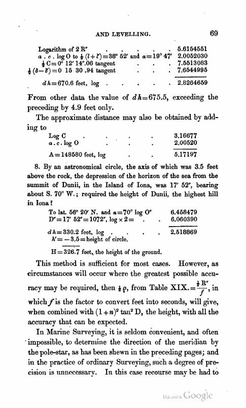
AND LEVELLING.
Logarithm of 2 R" . 6.6164561 a . c . log 0 to + ( I + Z') =38' 62' and a= 19' 47' 2.0062030 4 C= 0" 12' 1P.06 tangent , 7.6613083
d(d-#)=O 16 30 .94 tangent , 7.6644995
d hz670.6 feet, log . . 2.8264669 From other data the value of dh=6'75.5, exceeding the preceding by 4.9 feet only.
The approximate distance may also be obtained by add- ing to
L o g C . 3.16677 a . c . l o g 0 2.00520
A= 148580 feet, log 5.1'7197
8. By an astronomical circle, the axis of which was 3.5 feet above the rock, the depression of the horizon of the sea from the summit of Dunii, in the Island of Iona, was 17' 52", bearing about S. 70" W. ; required the height of Dunii, the highest hill in Iona ?
To lat. 66" 20' N. and a=70° log 0" 6.458479 D"=17' 62"=1072", log x 2= . . 6.060390
d h = 330.2 feet, log . . 2.618869 h'= - 3.5 =height of circle. - H= 326:7 feet, the height of the ground.
This method is sufficient for most cases. However, as circumstances will occur where the greatest possible accu-
+ R racy may be required, then p, from Table XIX.=- f , in
which f is the factor to convert feet into seconds, will give, when combined with (1 + n)2 tali2 D, the height, with all the accuracy that can be expected.
I n Marine Surveying, it is seldom convenient, and often - impossible, to determine the direction of the meridian by the pole-star, as has been shewn in the preceding pages; and in the practice of ordinary Surveying, such a degree of pre- cision is unnecessary. In this c,ase recourse may be had to

70 TRIGONOMETRICAL SURVEYING
the' methods recommended in pages 28, 29, &c., as illus- trated by the following examples.
EXAMPLE 1. On the 10th of July 1837, a t 74~. M., in latitude 7" 31' 20" S., and longitude 153" 10' E., the ohserved altitude of the sun's lower limb was 10" 13' 0", and at the same instant the observed distance of the sun's nearest limb from a well-defined point of land on the same level with the eye to the left of the sun was 95" 16' 0 . The index-error of the former sextant was - 0' 5 0 , that of the latter + l' 10", the height of the observer's eye taking the sun's altitude being 14 feet; required the true bearing of the point of land, and the variation of the compass, when the magnetic bearing of the same poiilt was N. 5" 10' W. ?
h. m. 8.
Ship time, Ju ly 9, 19 0 0 To G . M. T. Sun's P. D. 1 f 2 2b 1% Longitude in time 10 12 40 E. Sun's semidiameter 15 45
Greenwich Mean T. 8 47 20
Obs. Alt. 1. 1. . 3b o Observed distance . 9°5 1'6 o Index error . - 0 50 Index error . . + 1 1 0 Dip to 14 feet . - 3 43 Sun's semidiameter . + 15 45 Semidiameter . + 15 45
Apparent central distance 95 32 55 Apparent altitude 10 4 1 12 Correction . - 4 6 6
True altitude . 10 36 16 #
Now by the rule of the circular parts of Napier, applied to the right-angled spherical triangle HOO, fig. page 28,
R x cos HO --cos 0 0 x cos H O , or cos HO=cos HO sec 00.
H a , or apparent distance, 95" 32' 55" cosine 8.985383 00, or apparent altitude, 10 41 12 sec 0.007599
H a , or H Z O , 95 38 49 cos 8.992982
the difference of the azimuths of the sun and the object. The sun's true azimuth ]nay be computed by a formula
similar to that for time, in page 20, thus :

AND LEVELLING; 71
T o w the'dm'muth. Rule. Set down the polar distance, the true altitude, and
the latitude, then find half their sum, and the difference between this half sum and the polar distance. To the log secant of the altitude add the log secant of the latitude, the log cosine of the half sum and the log cosine of the differ- ence ; half the sum of these four logarithms will be the log sine of half the azimuth from the meridian, to be reckoned from the sozcth in north latitude, and from the north in south latitude.
Polar distance . . 1102 i 0 f6 True altitude .. . 10 36 16 secant 0.007481 Latitude . . 7 31 20 secant 0.003754
Sum . 130 27 52
Half . 65 13 56 cosine 9.622153 Difference . . 47 6 20 cosine 9.832924
Half . $2 4k 6k sine 9.733156 2 --
Sun's true behring N. 65 29 48 E. Object to left of sun . 95 38 49
True bearing of object N. 30 9 1 W. Magnetic bearing N. 6 10 0 W.
Variation of compass . 24 69 1 W.
Ex. 2. On the 1st of May 1834, in latitude 33" 8' 0 N., longi- tude 16" 10' W., the height of the eye 18 feet, the following ob- servations were made to determine the true bearing.*
h. m. a.
Mean time 9 35 6 2 a . ~ . Obs. Alt. n 592 i5 i 0 0bs.Dist. 4 1 i l $4 6 Longitude1 440W. Diptol8ft - 4 1 2 S . D . . + 1553
Sun Dr. + 15 53 Red.G.T. 10 40 32 App. Dist. 111 49 53
App. Alt. 52 37 11
* The marks mean the sun's lower limb,:and 4 shews the position of the sun in the &oss wires of the telescope, &c.

72 TBIOONOMETRICAL SURVEYING
App. Alt. 5°2 1"l Correction - 39 a ' s Pol. Diat. 76' (Y 10
True Alt. 62 36 32
Polar diatance 7% 6 f0 True altitude . 62 36 52 secant . . 0.216631 Latitude . . 33 8 0 secant . . 0.077067 Sum . . 160 44 42 Half . . 80 22 21 cosine . . 9.223345 Difference . 6 22 11 cosine . . 9.998090 Sun's bearing 5.69 48 40 E. Reduced versine 9.516133
Apparent altitude . 602 & fi secant . 0.216738 Apparent distance . 111 49 53 cosine . 9.570399 Z t o t h e r i g h t . 1274625 cosine . 9.787137 Sun's bearing . S. 69 48 40 E.
True bearing of object S. 57 67 46 W.
Should the object in Example 1. be not on the level of the eye, the following method of computing the angle HZ8 must be employed.
App. Cent. Diat. (D) 905 & 66 Z. D. of point observed 90 0 0 cosecant . 0.000000
, Sun's apparent Z. D. 79 18 48 cosecant . 0.007600 -- -
Sum . , 264 51 43
Half (HI . 132 26 61.5 sine . 9.868110 Difference =P- D= 36 52 66.6 sine . 9.778277
19.653987
Half . . 47 49 24.6 cosine . 9.826993 2
Angle at zenith . 96 38 49 as before,
and this plan must be always followed when both zenith- distances differ considerably from 90°, or even when it is doub@l if the object be on the same level with the eye.
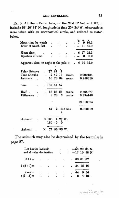
AND LEVELLING. 73
Ex. 3. At Dmii Cairn, Iona, on the 21st o f August 1839, in latitude 56" 20' 34" N., longitude in time 25" 34"., observations wer;! taken with an astronomical circle, and reduced as stated below.
h. m. s. Mean time by watch . . 7 9 46.2 Error of watch fast . . - 11 64.0 Mean time . 6 67 62.2 Equation of time - 3 0.2
Apparent time, or angle at the pole, t . 6 64 62.0
Polar distance . 751 i 9 5 True altitude . 2 42 16 secant 0.000484 Latitude . . 66 20 34 secant 0.266316
Sum . 136 61 52 Half . . 68 26 66 cosine 9.666377 Difference . . 9 23 6 cosine 9.994148
64 2 13.6 sine 9.908162 2
Azimuth . 8.108 4 27 W. 180 . 0 0
Azimuth . N. 71 66 33 R
The azimuth may also be determined by the formula in page 27.
Let 1 =the latitude . =5°6 2b 34 N. and d =the declination . . =12 10 68N.

74 TRIGONOMETRICAL SURVEYING AND LEVELLING.
h. m. 8. - * t = 3 27 -26 cot 9.895022 . . 9.895022 * ( I - d) = 22" 4' 48" cos 9.966920 sine . . 9.575073 4 (1 + d)=34 15 46 cosec 0.249500 seo . . 0.082776
&(m+ e)=52 16 18.5 tan 10.111442 &(m-e) = 19" 3Y 1W.6 tan 9.552871 i(m-e)=19 39 18.6
Change of azinluth in m=N. 71 55 37.0 W. 10 minutes . 2" 3' 5P.0
1 . z= 108 4 27.0 1 mindte . 12 23 .4 2 . z=S.108 4 23.0 W. I0 seconds . 2 3 .9
1 second . 12.39 Mean= S.108 4 25 W.
Arc= 68 54 3 or horizontal angle a t Dunii by the circle to Carn Cul -- r i Eirn. S. 39 10 22 W. the bearing of Carn Cul r i Eirn from Carn Duni i
in Iona.
Ex. 4. On the 11th of August 1841, at my station, in latitude 55" 27' 56.74 N. longitude, 4" 37' 3 5 W., a t 4h 40" 17y5 mean time, by observations on the limbs of the sun, taken alternately above and below the central horizontal wire, and to the right and left of the vertical wire, in opposite quadrants of the diaphragm, so that the mean of all might be that of the suh's centre at the intersection of the wires in the centre of the telescope, I found the true alti- tude of the sun's centre, deduced from the vertical arc of my circle, to be 24" 25' 45 , when the polar distance was 74" 47' 14" ; while, by the horizontal arc, the angle between the sun's centre and Ayr High Spire, was 2" 52' 23 .3 W., distant 1152 feet; re- quired the latitude and longitude of the spire ?
ANS. The azimuth of the sun . . S. $1 i 6 36.8 W. . . . ... spire . . 5.84 9 0.1 W.
Reduction of station to spire, in lat. . - 0 0 1.16 S. ... ... ... , in long . + 0 0 19.88W.
Latitude of spire . 56 27 56.58 N. Longitude of spire . 4 37 54.88 W. .
In a similar way the commoil theodolite may be-employed, and the result will be within a few minutes of the truth. Whence also the variation may be obtained by taking bear- ings at the same time by the needle.

RAILWAY SURVEYING.
1; IN the present times, when railways are constructing in all parts of the United Kingdom, as well as abroad, on account of their great importance and general utility, a re- commendation in favour of their adoption cannot now be necessary. However evident this general proposition may be, yet it requires much caution and considerable profes- sional knowledge, to select the lines in such a manner as to enable the country, as well as the public and shareholders, to derive the full advantage they are certainly calculated to produce. The surveyor undertaking such a work ought first to ascertain, by personal observation, the nature of the country through which it is intended to pass, with regard to its localities, its structure, and geological character. This might lead him to the choice of several lines apparently equally favourable, as far as a cursory inspection of the ground by the eye, chiefly through the medium of its lakes, rivers, and mountain-ranges, could determine.
2. In the selection of railways, too, the amount of traffic, to a certain extent, ought to regulate the nature of the con- struction. If there is a certainty of great traffic, the ex- penditure in tunnellillg, cutting, embanking, and viaducts, may be very considerable, in order to improve the gradients; but if a moderate trade only is to be expected, such an ex- penditure must be injudicious, because it increases the charges, or diminishes the profits, of the original share-


76 RAILWAY SURVEYING.
holders, and thus, unless at the expense of the public, they must receive an inadequate remuneration for their capital. Circuitoup lines, to serve inferior provincial towns, are not to be recommended, except to a limited extent, because the greatest amount of the whole traffic may be expected from the large towns at the extremities, for whose use chiefly the railway would be constructed, and through whose influence the bill for such a purpose must chiefly be carried.
The passengers between these towns would thus be com- pelled to pay fareg for these additional miles so thrown into the railway, while, at the same time, the duration of transit would be increased, by this means entailing a positive loss on the majority of the passengers, both in money and time. I t would generally, therefore, be better to connect these inferior towns with the main line by short branches.
The advantages, therefore, to be derived from the use of railways, are, rapidity of transit, and economy of charge ; to accomplish which, the following principles should be kept constantly in view :-
lo, One of the conditions which must not be departed from in laying out great lines of railway is, that those lines may be traversed throughout their whole extent by loco- motive engines ; and, in order-to avoid, as much as possible, interruptions and delays, that the same engine should draw the same train.
2", Another condition is, to diminish, as far as practica- ble, the time of transit between two given points, by re- ducing the length of the railway. In this case the straight line, either horizontal or having one uniform slope, will be the most advantageous. It is this line which ought to be selected, or the nearest practicable one to it, both horizon- tally and vertically.
3", If two lines may be chosen equally advantageow in

RAILWAY SURVEYING. 7 7
these respects, then that which passes through the most populous and richest country in minerals ought to be chosen.
4, I t would be a great error to suppose that the line may be lengthened circuitously ; because by that means, by get- ting easy gradients, the velocity will be much increased, since what is gained in velocity, it is obvious, may be easily lost in greater distance.
5", It was formerly supposed (and this hypothesis has been acted upoil by many engineers) that the entire line of railway should, as nearly as possible, have one uniform slope, with very good gradients, however circuitous almost the line might be made to obtain them.
6", Now, within certain limits, this is doubtless true ; but i t requires great care and considerable science to be able to determine these with tolerable accuracy in practice.
7", I t has been a maxim with some engineers, that if a uniform slope is impracticable, or if it requires too great a deviation from the straight or direct line, it is necessary, at least, to endeavour to rise progressively from one extremity of the line to another, and never to ascend where it must descend again.
8", But it is clear that such views are, within certain limits, illcorrect; for, if the traction be increased by gravity, when a train or engine is impelled up an inclined plane, in proportion to the rate of rise, it will be diminished in nearly the same proportion when it descends, especially when the gradients are very good, never exceeding 1 foot in 300, and generally much less, in which circumstance the acceleration from gravity requires no check.
go, On this principle, the loss of velocity in ascending one side of a rising grouild or inclined plane will be nearly, but not exactly, compensated by the gain in descending the other, when the slopes are equal, ancl some aliquot pnrt of

78 RAILWAY BURVEYING.
it regulated by the difference, if they are nnequal, and this compensation will be the more nearly equal the better the slopes are, and the more perfect our engines become. In this last case, the ratio of the friction on'the inclined plane to that on the horizontal plane may increase, tirough the total e$ecl will be diminished. 10", Hence, in tracing a line of railway, there is no in-
convenience in rising higher to redescend afterwards, so long as that does not render it necessary to extend the limit of the slopes. Thus, for example, several lines uniting two given extreme points, upon which it is admitted that the same locomotive engine draws throughout the same train, will be perceptibly equal in respect to the expense of tran- sit, whatever be the height to which they rise or to which they descend, if their lengths be equal, and if, upon any of these lines, the steepest slopes do not surpass 1 in 200, so as to produce an inconvenient or dangerous acceleration. Hence it appears that special care should be taken to dimi- nish the length of the line of transit, to lower the limit of the slopes, and that it is unnecessary, for the sake of re- markably favourable gradients, to involve a railway com- pany in extravagant expenses, in order to complete tunnels, make embankments, and construct viaducts, the interest of the money required for which frequently exhausting a con- siderable portion of the revenue of the speculation, and di- minishing the dividends of the shareholders, who ought, in all cases, to receive a fair remuneration for the money they may have advanced.
11°, To select the cheapest and most efficient line of rail- way, depends upon the following proposition :-To combine the distance between two given points with the gradients in such a manner as to produce the greatest efect at the least expense.
RAILWAY SURVEYING. 79
Though this proposition, in general, cannot be solved di- rectly, yet, by attending to the preceding principles, an a p proximate solution may be obtained, by the aid of the tables accompanying this work, sufficiently accurate for all ordi- nary purposes.
12", 1n estimating the mean value of the gradients through- out a line, the value of each,- with its proper sign, must be multiplied by its length, and the algebraical sum of the products divided by the length of the whole line, including the levels in the same measure, will be the mean value of the gradients, in which the signs of the ascents must be reckoned positive, and those of the descents negative.
13", If the force of tractiou obtained in this way on two lines connecting the same two extreme points be inversely as their lengths ; or if the product of the length of one line, multiplied by its force of traction, be equal to the product of the length of another line multiplied by its force of trac- tion, the effects of those two lines would be equal, or equal tonnage would, by equivalent locomotive engines, be trans- ported along each line in equal times. This follows from the fact, that, if the traction on a unit of the line, such, for example, as one mile, be multiplied by the whole length in . miles, the produc$ will be the total traction throughout the line, and it will express the power expended in propelling an engine throughout the whole line. Hence the relative effective powers of two lines of railway may be easily esti- mated, and their respective advantages and disadvantages readily determined.
14", As the length of a line of railway is one of the ele- ments employed to compute the expense of transit, it is clear it should be as short as convenient and sound piin- ciples will admit, because it will also reduce the time of transit. It would be committing a great error to suppose

I
80 RAILWAY SURVEYING.
we may lengthen the line because the velocity of transport l
over it is great. The same principle which rendered the establishment of a railway necessary or desirable, in order to obtain a mode of transport quicker than any other, re- quires that the shortest lines should be sought after, and even to prefer them, when sometimes they appear disadvan- tageous in other respects.
150, In order to ascertain the effects .of slopes, experi- ments have been instituted to determine the amount of I
tractive force necessary to propel a ton of burden on a level 1 plane or horizontal line of a well constructed railway. This, of course, varies a little with the quality of the railway, as well as with the constructio~~ of the carriages, and depends on the total amouilt of friction. I n general it varies from 8 lb. to 9 lb. per ton, and is therefore very generally as- sumed at &$ lb. per ton, an approximation, in the present state of railway carriages, not far from the truth. Now, in one tan there are 2240 lb., consequently, if 2240 1b. be divided by 8.5 lb., the quotient is 264, ail abstract number, from which it is inferred that the traction on the level plane is equal to 1-264th part of the weight drawn. But, by the principles of mechanics,-The w 4 h t moved upon an inclined plane, is to the power by which it is moved, as the length of the inclined plane is to its height.
Suppose, for example, that a waggon enters upon an in- clined plane rising 20 feet in an English mile of 5280 feet, or 1 foot in 264 feet, it follows, from the preceding analogy, that an additional 8& lb. will be combined with that on the level, or that twice the force will be necessary to propel the carriage with its load up this ascent at the same velocity as oil the level, that is, if 84 lb. per ton be required to propel :t carriage or t r i l l of waggons at the rate of 30 miles an hour on the level, it would require doecbk that force of trac-

RAILWAY SURVEYING. 8 1
tion, or 17 1b. per ton, to keep up that velocity on an in- clined plane or slope rising 1 foot in 264, or 20 feet in a mile.
It also follows, from the same process of reasoning, that a velocity of 30 miles an hour might be kept up on ascend- ing that inclined plane, if the train of waggons carried a part of the 'load only. It is frequently observed that an undulating line, having collsiderably steep slopes, limits the load to what the locomotire engine can propel up these gra- dients,-a fact undoubtedly true. But no slopes so steep a3 to nearly stop .the trains proceeding at the rate of 30 miles an hour on the level should be admitted on any railway, un- less from unaveidable necessity, and in that case a station- ary engine must be employed at those points where they may be required. I n all lines where the gradients are not more than 1 in 300, no such occurrellce can take place; and to expend large sums of money on tunnels, cuttings, em- bankments, and viaducts, or circuitous lines for better, must be considered a useless expenditure of the public money.
Again, if the rise be 1 in 2000, it will require an addi- tional force of 1.12 1b. per ton, which, added to 8.5 lb., that on the level, gives 9.62 lb., the necessary tractive force up this inclination, similarly as before. In this way we arrive at a distinct knowledge of the exact amount of tractive power necessary to propel any load up an incli~zed plane, whatever be its rise per mile, or its inclination.
If, on the contrary, the train be moving down the d e scending plane, then the tractive force necessary on the level plane will be dinlinished by the effects of parity, to keep up the same velocity on the inclined plane as on the level. Hence, if the power be constant, there will be a re- tardation in ascending the inclined plane, and a correspond- ing acceleration in descending, which will, in we1.l-construct- ed railways, whose gradients do not exceed 1 in 300, nearly
F

82 RAILWAY SURVEYING.
counterbalance each other. The modifications on this ac- count may be obtained from the accompanying tables. '
Indeed, absolute accuracy is hardly to be expected in such cases, since a suufficient number of experiments on all sorts of inclinations, in different 'circumstances, to be com- bined with mathematical investigations, have not yet been completed. In the first .table, by Mr Barlow, I believe, though it may give a good approximation to the truth, i t appears singular that there should be snch disruption of the - law of continuity on the descending plane at about 1 in 140. I t appears somewhat strange, that a change from 1 in 140 to 1 in 160 should change abruptly the equivalent horizontal plane from 1.00 to 0.83 ; while from 1 in 160 to 1 in 180 it does not change at all, and even continues the same to 1 in 500, while, by the experiments of Dr Lardner, he finds a complete compensation of velocity from 1 in 177 to the de,d level, and there is no dangerous acceleration on inclined planes of considerable steepness, so that, after ac- quiring a certain velocity, the motion becomes uniform. No doubt this must be true when the friction, combined with the resistance of the atmosphere, become equivalent to the acceleration from gravity. More numerous experi- ments, I suspect, are yet required to ascertain the precise limits, in given circumstances, within which this c o m p e m tion takes place. Though I am disposed to put greater confidence in IkIr Barlow's views on most points than in Dr Lardner's ; yet, in the present case, from the remarks I have made above, and what has occurred to my own knowledge, it mould appear that there is some foundation for Dr Lard- ner's results.
On the preceding principles will be compared the relative merits of two assumed lines of railway, in which the values of the respective gradients are given in a column adjacent
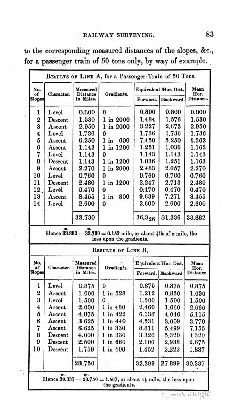
RAILWAY SUXVEYING. 83
to the corresponding measured distancesof the slopes, Bc., for a passenger train of 50 tons only, by way of example.
RESULTS OF LINE A , for a Passenger-Train of 50 Tons.
No. of
slopes
1 2 3 4 5 6 7 8 9
10 11 12. 13 14
Mean Hor.
Distance. --
0.800 1.530 2 950 1.736 6.362 1.163 1.143 1.163 2.270 0.760 2.480 0.470 8.455 2.600
33.882
BIeasnred Distance in &Ides.
0.609 1.530 2.950 1.736 6.250 1.143 1.143 1.143 2.270 0.760 2.480 0.470 8.455 2.600
33.730
m.
Character.
Level Descent Ascent Level Ascent Ascent Level Descent Ascent Level Descent Level Ascent Level
m.
Equivalent Hor. Dist.
Hence 33 882 -33.730 = 0.152 mile, or nbout 4th of a mile, the loss upon the gradients.
RESULTS OF LINE B.
Gradients.
0 1 in 2000 1 in 2000 0 1 in 600 1 in 1200 0 1 in 1200 1 in 2000 0 1 in1200 0 1 in 800 0
Forward. --- 0.800 1.484 3.227 1.736 7.450 1 251 1.143 1.036 2.483 0.760 2.247 0.470 9.639 2.600
36.326
No. of
dopes
1 2 3 4 5 6 7 8 9
10
Backward
0.800 1.576 2.673 1.736 5 250 1.036 1.143 1.251 2.057 0.760 2.713 0.470 7.271 2.600
31.336
m m. Hence 30.337- 28.750 = 1.587, or about 14 mile, the loss npon
the gradients.
Character.
Level Assent Level Accent Ascent Ascent Ascent Descent Descent Descent
Gradien+e.
0 1 in 528 0 1 in 480 1 in 122 1 in 440 1 in 330 1 in 330 1 in 660 1 in 106
Rfeasured Distance in Miles.
0.875 1.000 1.500 2.000 4.875 3 625 6.625 4.000 2.500 1.759
28.750
Mean Hor.
Distance.
0.875 1.030 1.500 2.060 5.115 3.770 7.155 4 320 2.675 1.837
30.337
Equivalent Hor Dist.
Forward. ---------- 0.875 1.212 1.500 2.460 6.138 4.531 8.811 3.320 2.100 1.452
32.399
Backward
0.875 0.830 1.500 1.660 4.046 3.009 5.499 5.320 2.938 2222
--a_-
27 899

81 RAILWAY SURVEYING.
On comparing the results of these two lines, designated by A and B, it appears that A loses only about m-seventh of a mile, while B loses about a mile and a hay in steampower or in time by means of the gradients abne, when the effects of the slopes are estimated by hfr Barlow's tables ; but this does not give a proper estimate of the relative expenses of the lines. This is obtained from a comparison of the mean horizontal distances in the righbhand colimns. Thus A has 33.882 miles of mean horizontal distance, while B has only 30.337 miles. The difference of these is 3.545 miles, the loss of A above' B, in passing once along the line, and of course double of this, or about 7 miles, in one trip forward and back, of steam-power or of time. These conclusions are independent of 5 miles of actual measured distance, for the construction of which additional miles funds must be provided, which causes an immense loss, or useless expen- diture of money to the shareholders of A's line, while tha t of B is more effective.
Besides entailing the expenses of construction on the shareholders for-these additional useless 5 miles, the ex- penses of transit over them must be charged on goods w d passengers, thus compelling those who use the railway t o siffer a se'rere 'aiinual loss,' without any equivalent 'advan- tage. These injudicious skhemes 'will no lonier be toler- ated, as the Legislature now (1841) &mploy, ~ e r ~ ~ ~ r o ~ e r l ~ ,
'I men of competent science to examine, them before an act for their execution can be obtained. So much for the be- nefit conferred on the public by injudicious speculators i; railqays. In fact, they materially injure the public as zvell as themselves.
pence, from ,this.investiga$on, great eare should be taken to avoid e&nding the lines too much for the sake of good slopes, wherebyxmke may be easily lost in distance than oained by good gradients. Hence, too, the policies, or falicy h
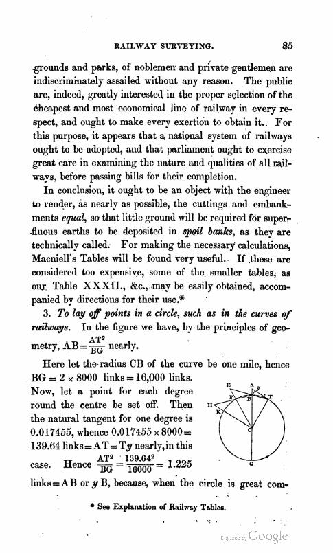
RAILWAY SURVEYING. 85
grounds and parks, of noblemen and private gentlemen are indiscriminately assailed without any reason. The public are, indeed, greatly interested in tbe proper selection of the dheapest and most economical line of railway in every r e spect, and ought to make every exertion to obtain it. For this purpose, it appears that a national system of railways ought to be adopted, and that purliameilt ought to exercise great care in examining the nature and qualities of all ra,it- ways, before passing bills for their completion.
I n conclusion, it ought to be an object with the engineer to render, as nearly as possible, the cuttings and embank- ments equal, so that little ground will be required for super- .fluous earths to be deposited in spud banks, as they are techllically called. For making the necessary calculations, Macniell's Tables will be found very useful. If .these are considered too expensive, some of the smaller tables, as o w Table XXXII., &c., .may be easily obtained, accom- panied by directioils for their use.*
3. To lay of points in a circle, such as in the curves of railways. In the figure we have, by the principles of geo-
AT2 metry, AB = - nearly. BG
Here let tbe.radius CB of the curve be one mile, hence BG = 2 x 8000 links = 16,000 links. Now, let a point for each degree round the centre be set OR. Then IIm the natural tangent for one degree is 0.017455, whence 0.017455 x 8000= 139.64 links=AT= Ty nearly,in this
AT2 139.642 case. Hence --- = ----- - 1.225 0
BG 16000 - links=AB or y B, because, when the circle is great com-
. . * See Explanation of Railway Tablea.
';.

86 RAILWAY SC?1OEPING.
pared with T A or T y, then A B and y B must be nearly equal.
Again, produce the chord T B to subtend another de- gree, making BE = TA, or rather T y, then EF = 2 y B = 2 x 1.225 = 2.45 nearly. Again, through B and F produce the chord B F to H, (so as to subteud another d e ~ e e , and make HK=2.45 links as before, and K will be another point in the circle; continue this process till the whole curve is completed by points, and then soften the pointa into a continuous curve by any pmacti&l method that may readily occur.
I believe an instrument for accomplishing this has been invented by Mr Brunel, which is easy in its application and sufficiently accura,te in practice.

DESCRIPTION AND USE
OF
T H E I N S T R U M E N T S
EMPLOYED IN
TRIGONOMETRICAL SURVEYING AND LEVELLING.
DEFINITIONS
NECESSARY TO BE KNOWN I N ORDER TO UNDEBSTAND THE USE OF
INSTRUMENTS.
1. When angles are measured on a level plane, similar to the surface of the sea or a lake, they are called horizontal angles.
2. When angles are measured on a plane, perpendicular to the level plane, they are called vertical angles.
3. If angles are measured in neither of these planes, they are said to be take; in oblique or on inclined planes.
4. If the angles be measured in the vertical plane, above the straight line passing through the eye of the observer per- pendicular to the plumb-line, they are called angles of ek- vation ; their complements to 90" are called zenithdistances ; and the angular instruments, such as theodolites, altitude and azimuth circles, kc. are commonly constructed so as to read either way according to the orders of the observer.
5. When angles are taken below the level or horizontal line defined above, they are called angles of dqression; though,when the instrument r e d s zenithdihances, thie clis-

88 DESCRIPTION OF INSTRUMENTS EMPLOYED IN
tinction is unnecessary, because the excess above 90" is the depression.
6. These respective positions are known by means of the plumb-line or spirit-level, one or other of which is generally applied to all instruments requiring, in their application, a knowledge of these planes.
7. Those points are said to be in the same level which are equidistant from the earth's centre considered as a sphere. The earth, howeveis, is really a spheroid, having its polar axis less than its equatorial diameter by &, and in the more refined operations, it is the surface of this sphe- roid that is accounted the level.
8. In the measurement of altitudes, the height of the in- strument must generally be added to the fesult from cal- culation when situated at the bottom, but subtracted when at the top. The mean level of the sea, or that at half-tide, is generally adopted as the standard from which heights are estimated. If high or low water at spring-tides be as- sumed, this should be stated, and the rise of the tide re- corded.
9. To illustrate the preceding definitions and terms used in the mensuratioil of heights and . . z
distances on the earth's surface tri- gonometrically; let AHWR be a section of the earth at the surface of the sea, considered as a sphere, which for this purpose is sufficient- ly near the truth, then, if S be the = station of the observer at the height =' R '
A S, or h, above the mean level of the sea, Z N will be pointed out by the plumbline hanging freely, HS N
~er~endicnlar to Z N will be. indicated by the spiritlevel ;.
SURVEYING AND LEVELLING. 89
the point T will be the u t m ~ t limits of vision, or the sur- face of the sea at the distance T S or d, and to these lines distinctive names have been appropriated. The point Z is called the zenith, the opposite point N is called the nadir; H S , perpendicular to ZN, is called the horizontal line; H'C R, parallel to it, and passing through the earth's centre C, is called the .true horizon; and S T the distance of the visible horizon where the sky and the extreme limits of the surface of the sea appear to meet. When observations are made with angulas instrun~ents, as the theodolite, the alti- tude and azimuth circles, the reflecting circle, Bc. on any object 0, in the direction SO ; the angle 0 S Z is called the zenith-distance, 0 S H the altitude, and H S T the depression of the horizon T S, below the horizontal line H S marked by the spirit-level, called also by seamen the dip of the ho- rizon. Independent of refraction, it is equal to the angle T C S measured by the arc AT. This arc has by Hors- burgh, Bc. been improperly given as the definition of the dip, though, as has been shewn, it is equal to it, and may be taken as a measure of it only, without allowing for thg effects of terrestrial refraction.
THE SPIRIT-LEVEL.
The spirit-level iq a cylindrical glass-tube AOB, of a uni- form diameter throughout,,which is carefully ground into the form of a circular arc of large radius, occasionally of several hundred feet, which makes it appear nearly straight.
It is then nearly filled with some fluid, as alcohol or ether, and the ends are artificially closed or hermetically sealed. To the upper surface of fine instruments there is adapted a scale having divisions cut on a slip of ivory, or even on the surface of the glass itself, shewing single seconds or some multiple of the second, though in all the smaller portable
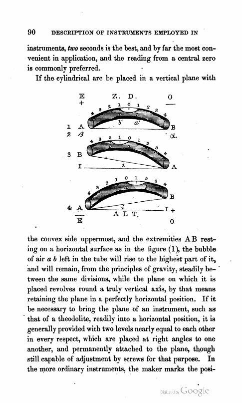
90 DESCRIPTION OF INSTRUMENTS EBIPLOYED IN
instruments, two seconds is the best, and by far the most con- venient in application, and the reading from a central zero is commonly preferred.
If the cylindrical arc be placed in a vertical plane with
the convex side uppermost, and the extremities A B r e s t ing on a horizontal surface as in the figure jl), the bubble of air a b left in the tube will rise to the highest part of it, and will remain, from the principles of gravity, steadily be- '
tween the same divisions, while the plane on which it is placed revolves round a truly vertical axis, by that means retaining the plane in a perfectly horizontal position. If i t be necessary to bring the plane of an instrument, such as that of a theodolite, readily into a horizontal position, it is generally provided with two levels nearly equal to each other in every respect, which are placed at right angles to one another, and permanently attached to the plane, though still capable of adjustment by screws for that purpose. In the more ordinary instruments, the maker marks the ps i -

SURVEYING AND LEVELLING. 9 1
tion of the bubbles when the plane is horizontal, and there- fore when the bubbles occupy these positions, the plane on which they are fixed must be horizontal. For common in- struments these marks are reckoned sufficient, and the di- vided scales are thought to be unnecessary.
I n fine instruments, if the plane of the level be inclined, by the unequal actton of heat upon its .supports or other un- avoidable causes, to the vertical, and the position of the ex- tremities of the bubble be noted, then if, upon reversing the instrument by turning it half round the vertical axis, at a second observation, they occupy the same positions as in (1) (2), where A and B merely exchange places and occupy those of a and 8 in a reversed position, the plane will be truly level, and have the same inclination to the vertical ZN in the preceding figure as it had before. This, how- ever, from different causes, almost never happens, and then it becomes absolutely necessary to record the reading of both ends of the level reckoned most conveniently, as in the figure, from a central zero, indicated from the positions marked (3) and (4). If the verniers of the instrument read zenith-distances, the reading of the extremities of the bubble on. the scale of the level next the observer, called the eye- end, is marked +, and that farthest from him, or the ohject- end, - . If the instrument reads altitudes, the signs must be reversed, that is, the eye-end must be reckoned -, and the objectrend +. If the divisions on the scale of the level do not shew single seconds, the difference between the positive and negative sums must be multiplied by the value of one division, and the result divided by twice the number of the observations, and applied to the degrees, kc., read from the circle, according to its sign, to give the true reading cor- rected for the inclination of the vertical axis.
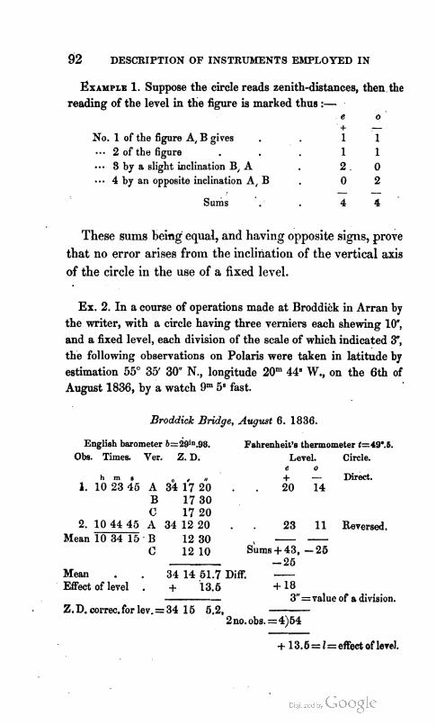
EXAMPLE 1. Suppose the circle reads zenith-distances, then.the reading of the level in the figure is marked thus :-
e o + -
No. 1 of the figure A, B gives . 1 1 2 of the figure 1 1
.-. 3 by a slight inclination B, A 2 . 0 4 by an opposite inclination A, B . 0 2
- - Sums 4 4
These sums being' equal, and having opposite signs, p o r e
that no error arises from the iriclination of the vertical axis of the circle in the use of a fixed level.
Ex. 2. In a course of operations made at Broddihk in Arran by the writer, with a circle having three verniers each shewing lo", and a fixed level, each division of the scale of which indicated 3", the following observations on Polaris were taken in latitude by estimation 55" 35' 30 N., longitude 20" 44"., on the 6th of August 1836, by a watch 9" 58 fast.
Broddick Bridge, August 6. 1836.
English barometer b=29in.98. Fahrenheit's thermometer t=4ge.5.
Obs. Times. Ver. Z. D. Level. Circle. e o
h m s + - ~ i r & . 1. 1 0 2 3 4 5 A 3% fi ib . . 2 0 14
B 17 3 0 C 17 2 0
2. 1 0 4 4 4 5 A 3 4 1 2 2 0 . . 2 3 11 Reversed. M e a n 1 0 3 4 1 5 , B 1 2 3 0 - -
C 1 2 1 0 S ~ S + 43, - 2 6 - 2 5
Mean . . 3 4 14 61.7 Diff. - Effect of level . + 13.6 + 18
- 3 =value of a division. Z. D. correc. for lev. = 3 4 16 5.2,
2no. obs. = 4)54
+ 13.6=l=effedoflevel.
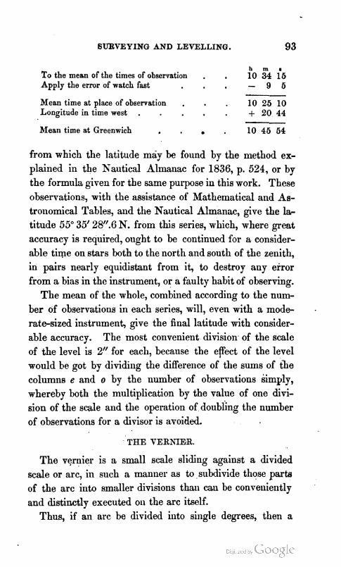
SURVEYING AND LEVELLING. 93
To the mean of the times of observation . . l"0 3m4 i5 Apply the error of watch fast - 9 5
Mean time at place of observation . . 10 25 10 Longitude in time west . . + 20 44
-- Mean time at Greenwich . . . 10 45 54
from which the latitude may be found by the method ex- plained in the Nautical Almanac for 1836, p. 524, or by the formula, given for the same purpose in this work. These observations, with the assistance of Mathematical and As- trollomical Tables, and the Nautical Almanac, give the l* titude 55" 35' 2W.G N. from this series, which, where great accuracy is required, ought to be continued for a consider- able time on stars both to the north and south of the zenith, in pairs nearly equidistant from it, to destroy any error from a bias in the instrument, or a faulty habit of observing.
The mean of the whole, combined according to the num- ber of observations in each series, will, even with a mode- . rate-sized instrument, give the final latitude with consider- able accuracy. The most convenient division of the scale of the level is 2" for each, because the e p c t of the level would be got by dividing the difference of the sums of tie columns e and o by the number of observations simply, whereby both the multiplication by the value of one divi- sion of the scale and the operation of doubling the number of observations for a divisor is avoided.
THE VERN1E.R.
The vernier is a small scale sliding against a divided scale or arc, in such a manner as to , subdivide those parts of the arc into smaller divisions than can be convelliently and distinctly executed on the arc itself.
Thus, if an arc be divided iiito single degrees, then a

small scale, having an extent equal to 59 of these degrees 1
divided into 60 equal parts, each part on the vernier will be
& less than one on the arc. But & part of one degree is equal to l', consequently such a vernier would, by the coincidence of any two lines--one on the vernier with one on the arc- shew single minutes. This vernier, however, would be rilr ther inconveniently long. If, therefore, the arc, as in the common theodolite, be divided into half degrees of 30' each, then a vernier scale of i 9 of these half degrees, divided into 30 equal parts, will also shew minutes, and the vernier scale, being shorter, is more .convenient. In this case, care must be taken not to forget half a degree in recording the read- ing indicated by the arrow which marks the degrees and parts on the arc. Generally, if n- 1 divisions on the arc be divided into n divisions on the vernier, then this vernier
1 1 1 1 1 1 1 1 1 1 1 1 1 1 1 1 1 1 1 1 1 1 1 1 1 1 1 1 1 1 1 1 1 1 1 1 1 1 1 1 1 1 1 1 1 1 1 1 1 1 1 1 1 1 1 1 1 1 1 1 1 I ' I ' I ' . I I I ' ] ' I i I " ' i ' ~ 10 8 6 4 2 1
V E R . 0 2 4 6 8 10
1 12-1 1 shews - part of the divisions on the limb, for 1- -=-
n n n*
-
Thus, if one degree, as in the figure, be divided into six equal parts of 10' each, and if 59 of these be divided into 60 on the vernier, then %=$= 10"; consequently, such e vernier shews 10" directly, and 5" may be easily estimated. Finer subdivisions than these are generally obtained by the reading microscope. If observations be repeated, however, ;In different parts of the limb, a degree of precision sufficient

SURVEYING AND LEVELLING. 96;
for almost the' nicest purposes may be easily obtained even by this vernier. Indeed, repetitions should be taken on different days, to avoid the irregularities to which the most powerful instruments are liable from the effects of refrac- tion. In using the different kinds of verniers, it will be found more easy, and less liable to error in reading off the arcs, when the degree on the limb and the minute on the vernier are similarly divided. Thus, if the limb be divided to 201, the vernier should shew 20"; if the limb read to 10: the vernier should read to loff, as in the figure, &c. By this arrangement, the mind is less liable to be distracted during the operation of reading, than when the limb is read according to one arrangement, and the vernier to another.
THE READING MICROSCOPE.
When the reading microscope is applied to read the divi- sions of an astronomical circle, the graduations in the arc generally indicate spaces ,of five m+tes each, which are read along with the degrees by means of an index pointer. The remaining minutes and seconds are determined by the reading microscope.
Method o/ Adjuet~)zent art? Application to Practice.
I11 the figure, A, A' represents the microscope, attached

96 DESCRIPTION OF INSTRUMENTS EMPLOYED IN
to the instrument by the arm I , and passing through its sup port B, formed by a collar embracing it, where it is firmly held by the milled nuts g, g', acting on screws cut upon the tube of the microscope. These nuts also serve the purpose of placing the instrument at the proper distance from the di- visions which it is employed to read, in order to obtain dis- tinct vision, and destroy parallax. 1; the body of the in- strument, at a, the common focus of the object and eye- glasses, are placed two wires, crossing each other diagonally at acute angles, which are made to traverse the field of view, backwards or forwards, by turning the micrometer head b, whose axis works in the box c, c', in the first figure. In the second figure is shewn the field of view, with the magnified divisions on the circle, as seen through the mi- croscope. The shaded part represents the diaphragm, with its cross wires, the angle between which may, by turning the micrometer-screw b, be bisected by any line on the circle within the field of view, as is shewn in the figure. On the left hand of the diaphragm appears the scale of minutes, from its shape called a comb, in which each tooth repre- sents a minute. Moveable with the wires along the comb, is a small index or pointer i, which, in the figure, is repre- sented at zero, the centre of the scale, known to be correct when it bisects the small hole at the back of the comb, while at the same time the cross wires bisect a division. Now one revolution of the screw b moves the point con- nected with the wires over one tooth of the comb, that is, over a space on the divided arc of the circle equal to one minute, and therefore part of a revolution moves them only over a part of a minute. T o determine the value of this fractional part of a minute in seconds, a large cylindrical head, e, e', is attached to the screw, having its exterior cir- cumference divided illto 60 equal -parts; ~eprkieriting se?

' . S,URVEYING AND LEVELLING. 97
con&, and read by an index opposite the eye of the observer at$ I n reading off an angle by this instrument, observe, first, the degrees and nearest five minutes shewn by the pointer on the graduated circle, then this will be the true angle, if, as in the figure, a division on the graduated circle bisect the angles of the cross wires. But if the cross wires be not thus bisect ed, read the deg~ees and nearest five minutes as before, then apply to the microscope, and; by turning the screw b in the order of the numbers upon the head e e', make the .nearest division in the reverse order of the numbers upon the gra- duated circle, nicely bisect the acute angles formed by the intersection of the cross wires; the number of teeth which the pointer i has passed over from its zero, to produce such a bisection, will be the number of minutes to be added to the degreea and minutes read off the circle by the pointer; and, lastly, the odd seconds a?zd estimated tenths to be added are taken from the divided head s e', as shewn by the in- dex$ In cases of great nicety, the run of the microscope may be taken to the next division in the direct order of the numbers upon the circle, which, subtracted from jive mi- nutes, ought to give the same number of minutes and se- conds as formerly, to be added to the arc shewn by the pointer on the circle. If there is a slight discrepancy, the mean of both may be taken and so applied.
1. To make the cross wires in the focus of the micro- scope and the divisions on the circle appear both at the same time distinct and free from parallax, draw out the eye-piece d, until distinct vision of the wires is obtained, and the divisions on the instrument are equally well defined and free from parallax ; that is, whether any motion of the eye causes the leaet apparent displacement of the wires with-
G

98 DESCRIPTION OF INSTRUMENTS EMPLOYED IN
respect to the graduations. If such a dancing motion be observed, the microscope must be moved to.or from the' circle, by turning the nuts g g', easing the one and tighten- ing the other, till the wires and graduations appear both distinct, and no parallax can be detected.
2. To make five revolutions of the micrometer-screw measure a five-minute space upon the graduated circle ex- actly. If the run of the screw has been carefully adjusted by the maker, and no alteration made in the body of the microscope, the image of the space between two divisions will be exactly equivalent to five revolutions of the screw,
when the wires and divisions are both seen distinctly. S u p pose, for example, however, that the microscope has been deranged, and the run is too great, and that the 5' space on the arc is equal to 5' 5", when measured by the microme- ter, thus making the image too large. But the magnitude of the image formed by the objecbglass of the microscope depends entirely on the distance of the object-glass from the limb, and, in the ordinary construction of the microscope, is diminished by increasing the distance between the objecb glass and the limb, and conversely. In the case supposed, the image is too large, consequently the object-glass must be removed farther from the limb, by turning the screw a t h inwards in the direction of B.* The image will not now be formed a t a, as it ought to be, but nearer to B, and distinct vision must again be obtained by bringing the whole body of the microscope, by the screws g g', nearer to the limb. By a repetition of two or three more cautious attempts in this way, five revolutions of the screw carrying the cross wires will correspond exactly with the image of the space between two divisions, which, for greater security,
* This is sometinles done by moving the part A', and fixing it by k.

BUBVEYIKO Ah'D LEVELLING. 99
may be read to the right and left on each side of zero. The screw c' gives motion to the comb or scale of minutes; and
'
the . micrometer-head, being adjustable by friction, a n be made to read either zero or any required second, when the cross wires bisect any particular division, by holding fast the milled head b, and at the same time turning the divided arc e e' round till any required division, as zero, coincides withL the index.
THE TELESCOPE.
All instruments capable of now giving results possessing the requisite accuracy are furnished with one or more tele- scopes. The rays of light ~roceeding from distant objects move in straight lines, unless they are reflected or refracted by some medium, such as metal, glass, &c., and also in pa- ranel lines nearly, especially if the object from which they come be remote.
Let AB represellt the section of a lens, such as the ob- ject-glass of a telescope. Let
- A the parallel rays coming from
D some distant object on the left -
B beyond C strike the glass lens AB, they mill pass through it, suffering refraction, and, on leaving the lens at the opposite side, they will converge and meet in the straight line CD at a certain point D, called the focus of the lens, where the eye, by a little practice in selecting the proper distance, will see an inverted image of the distant object in the air. Now, suppose two of these le~lses are applied to A
the construction of a P= "7
telescope, the image of -E B H
a distant object will be .formed at W, the focus of the object-glass AB, where, by

100 DESCRIPTION OF INSTRUMENTS EMPLOYED IN
moving the eyeglass or lens DF till its focus comes to the same point W, by means of two slides GH, IK, the eye of the observer at E will view a magnified inverted image of the object formed by the object-glass AB, with the eye-glass DF as a microscope. Since both these lenses are capable of motion, they may always be moved in such a manner that their foci will meet exactly at W, making the central line CWE a straight line, technically called the optical axis, or line of collimation of the telescope, from which the readings in all mathematical and astronomical instruments are taken. This point, W, is marked by fine wires, hairs, silk fibres, or spider lines, and this is the rea- son why both glasses must be moved till the telescope pro- duce distinct vision, and the wires are well seen, in which case the telescope is said to have no parallax.
If this adjustment is imperfect, the object will, on mov- ing the eye up and down a little, start from the intersection of the wires, thus causing an uncertainty in all observations, which must be instantly corrected. The point W, or focus of the object-glass, varies with every change in the distance of the object, and therefore this adjustment must be fre- quently examined, and, if necessary, corrected for terrestrial objects, though it remains constant for celestial. This in- strument is commonly called the astronomical or inverting telescope, because it wants other two lenses between the object and eye glasses to view objects erect as they appear to the naked eye. They are, however, almost universally employed for astronomical purposes, where it is less neces- sary to see objects erect, and because they appear more die tinct, from a greater quantity of light being attainable, since each lens absorbs a portion of it. It is scarcely necessary to add, that no attempt at adjustment should be made dur- ing, but always before, an observation.

SURVEYING AND LEVELLING. 101
THE THEODOLITE.
Of all angular instruments, the theodolite, properly con- structed, is that best suited to the purposes of the surveyor. I t has been formed on a great variety of plans, but that most approved for general purposes is the five-inch theodo- lite, divided by one or two verniers to minutes in both the horizontal and vertical arcs. It would be an improvement, for nice purposes, if the vertical arc were an entire circle, having the telescope passing through its centre, and capable of reversion like the common portable astronomical circle, though this is perhaps unnecessary for the ordinary prac- tice of a common land-surveyor.
Description.
The instrument consists of an under circular plate divided commonly into degrees and halfdegrees, usually called the horizontal limb at AA, on which an upper circular plate, called the vernier-plate, turns freely, that by means of one or two verniers, E, subdivides the halfdegrees on the lower into minutes. Both plates have an easy though steady motion round the axis, which, for that purpose, is slightly conical.. The internal centre also fits into a ball working within a socket at D, and the parts are held together by an internal screw at the lower end of the axis, within the tri- pod formed by the legs.
The diameter of the lower plate is a little greater than that of the upper, and its exterior edge is cut off in a plane inclined to the axis, which is technically called chamfered; and in the best instruments is covered with silver, to re- ceive the graduations, being less liable to become obseur~ by the action of the atmosphere than the metal of which the plates are made. On the opposite ends of an imaginary

102 DESCRIPTION OF INSTRUMENTS EMPLOYED IN
diameter, at the distance of 180" from each other, a small space, E, is also chamfered and covered with silver, form-
ing, with the edge of the lower plate, a continued inclined plane, on which the proper divisions being cut constitute the verniers. When the lower limb is graduated to thirty minutes, the vernier has 'a space equal to twenty-nine of them divided into thirty, and each, consequently, reads to minutes, which, by means of a microscope, either attached' or detached, may by estimation, when thought necessary, be carried to thirty or even twenty seconds. For fine purposes, the degree is divided into three equal parts, each

SURVEYING AND LEVELLING. 103
of twenty minutes, and, on the vernier-plate, a space equal to fifty-nine of these being divided into sixty, then this ver- pier indicates twenty seconds.
The two parallel plates under the graduated limb at F and G are held together by a ball and socket at D, and are set firm by four milled-headed screws H, H, H, H, which turn in sockets fixed to the lower plate, while their heads press against the under side of the upper, thus, acting on the vertical axis by means of the ball arid socket, render the horizontal and vernier plates truly level when the' instru- ment is prepared for observation.
Beneath these parallel plates is a female screw, within which the male screw lays hold of the axis, and keeps it firmly to the stand. The lower parallel plate is connected by brass joints to three mahbgany legs, having their lower ends pointed with metal, for entering the ground, and f r e quently so constructed, that, when shut up, they form one round staff, secured in that form for carriage by rings placed upon them. When the legs are opened out they make a firm stand, however uneven the ground may be. Some- times the legs are round or cylindrical, and formed of two parts, which unscrew for packing in a box, to facilitate their carriage when travelling. In this case, shods should be pre- pared to screw on the upper half, to be used when any nice observations are to be made requiring great steadiness in the stand.
The lower horizontal limb can be fixed in any given po- sition by the clamping-screw I, which causes the collar K to embrace the axis C, and prevent it moving. I t is gene- rally necessary that the telescope should be fixed in some precise position, more exactly than it can be by the hand alone. For this purpose, it is first made nearly correct by the hand, the parallel plates being previously clamped with

the verniers, and by the tangentscrew accurately set to the given positions, as zero and 180" ; then the instrument is moved a small quantity, by turning the slow-motion screw L, attached to the upper parallel plate, till the direction of the cross-wires of the telescope is perfected. I n a similar manner, the upper or vernier plate being now released, the telescope may again be placed upon any other object whose angular distance from the first is required, which, by the clamping and tangent screws, may be rendered perfect as before, and the angle shewn by the verniers must now be read and recorded. Before proceeding to measure the ho- rizontal and vertical angles, the parallel plates carrying the divisions and verniers must be made perfectly horizontal by two spiritlevels N N, placed at right angles to each other, and rectified by their adjustifig screws for this purpose. Upon the vernier-plate, too, is commonly placed a compass between the levels, for the purpose of taking magnetic bearings.
The vertical frames Q Q support the pivots of the hori- zontal axis of the vertical arc PVP, on which the telescope is placed. There is sometimes an arm carrying a micro- scope for reading the altitudes and depressions measured by this arc, and determined by the vernier V, which bas a ' motion of several degrees, so as to be placed opposite the divisions of coincidence. There are, on this vernier, two sets of divisions reading in opposite directions, of which the upper reads elevations, and the lower depressions.
Another screw S clamps the end of the horizontal axis seen at Q while a slow-motion or tangent-screw, T, moves the vertical arc and telescope, till a perfect observation be made. One side of the vertical arc is inlaid with silver, and is divided into single minutes, or lower, with the assist ance of its vernier. On the other side there are sometimes

SURVEYING AND LEVELLING. 106
placed divisions, to shew the difference between the hypo- telluse and base of a right-angled triangle, the hypotenuse being 100, or, which comes to the same thing, the number of links to be deducted from each chain's length in measur- ing up or down an inclined plane, to reduce it to the hori- zontal measure. If the angle of elevation and depression be taken, these afford data to take this reduction more ac- curately, from a table calculated expressly for this purpose, or the deduction may be readily made by a table of natural versed sines. The level which is shewn at K', under and parallel to the telescope, is attached to it at one end by a joint, and at the other by a capstan-headed screw, and will permit the level to be placed parallel to the optical axis of the telescope, comnlonly called the line of collima6ion. The screw at the opposite end is employed to adjust it laterally, so that it may be placed parallel to the axis also in a verti- cal plane. I n this way the level is placed parallel to the axis of vision, both horizontally and vertically. The tele- scope has two collars or rings of gun-metal, ground truly cylindrical, on which it rests on its supports XX, called Ys, from their resemblance to that letter, and it is confined in its place by the clips Z Z, which may be opened by re- moving the pins Y Y, for the purpose of reversing the telescope in double observations, when great accuracy is required. These pins should, to prevent loss, be secured by silk strings connecting them with the frame.
I n the focus of the eye-glass are frequently placed threev fine wires or lines of spider-web, one horizontal and two .
crossing it nearly vertically, making with each other a small or acute angle. This method of fixing the wires is prefer- able to having one horizo~~tal and another vertical, crossing one another at right angles, as is commonly the case, esye- cially for horizonhl angles, because a distant object can. be

106 DESCRIPTION OF INSTRUMENTS EMPLOYED IN
made to bisect the small angle between the vertical wires with more certainty than the object can be bisected by the vertical wire. For many astronomical purposes, however, the second method is preferable ; and for making observ* tiom on the sun, one or two coloured glasses should be pro- vided, to be fitted on the eye-end of the telescope. The screws for adjusting the cross-wires are shewn near the eye- end of the telescope at a, a, a, a, of which there are four, equidistant from each other. Hence the imaginary line joining any two opposite screws is a t right angles to the line joining the other two, so that, by $rst easing the one, and t h n tightening the other opposite to it, the intersection of the cross-mires may be readily adjusted. The object- glass, o, is moved by turning the milled-head b, on the side of the telescolje, till the object is seen well defined, while a corresponding motion is given to the eye-glass, e, by moving i t with the hand in its slide till the wires are seen equally distinct, which will easily be effected in one or two trials. The reason and effects of this process will be readily com- prehended by consulting the description of the last figure, p. 99, though the arrangement there is somewhat different.
A brass plummet and-line are also packed in the box with the theodolite, to be suspended from a hook truly un- der the centre of motion of the horizontal arc, by which i t can be placed exactly over the station whence the observ* tions are taken, an operation to be carefully performed in all fine work, otherwise considerable errors may arise, and sur- veys cannot close accurately. I f required, two extra eye- pieces are furnished for the telescope, to be used in astro- nomical observations. The one inverts the,pbject, has a greater magnifying power, but, with fewer lenses, possesses more light. The other is a diagonal eyepiece, which, with- out inconvenience, will enable an observer to see objects

SURVEYINQ AND LEVELLING. 107
having a considerable altitude. A small cap, containing a dark-coloured glass, is made to apply to the eye-end of the telescope, or to either of the preceding lenses, to screen the eye of the observer from the effects of the sun's rays, when that object is observed. A magnifying-glass, a screwdriver, and a steel-pin to turn the capstan-screws for adjustments, are also furnished with the instrument. I n some theodo- lites, the telescope passes through the horizontal axis, the supports are made sufficiently high to allow the telescope to pass under them when the instrument is reversed in azi- muth, and it then becomes an astronomical altitude and azimuth circle. With these additions, a, well-made theodo- lite may perform most of the problems in practical astro- nomy with considerable accuracy, though such an instru- ment would be rather too good for the usual purposes of sur- veying, which may be very well effected by an inferior in- strument.
1. The first adjustment is to make the intersection of the cross-wires coincide with the axis of the cylindrical rings on which the telescope turns, called rectifying the line of col- limation. This is known to be correct when the eye, look- ing through the telescope, observes the intersection of the wires continue on the same point of a welldefined distant object during an entire revolution of the tube of the tele- scope in the Ys. First make the intersection of the wires, when the level is under the telescope, coincide with some welldefined distant object; then turn the telescope half round in its Y s till the level lies above i t ; and if the same point is still cut by the intersection of the wires, the adjust- ment is correct in that position. If not, move the mire one- half the deviation, by turning two of the opposite screws a t

108 DESCRIPTION OF INSTRUMENTS EMPLOYED IN
a a, taking care to release one before tightening the other, and correct the other half by elevating or depressing the telescope. Proceed in like manner with the other position, by placing the level alternately on the right and left.
Now if the coincidence of the cross wires with the mark remains exact during a complete revolution of the telescope in the Ys, the line of collimation is correct ; if not, the same operations must be repeated till it is so.
2. The second adjustment is that which places the level attached to the telescope parallel to the rectz$ed line of col- limation. The clips Z Z, being open, and the vertical arc PVP clamped, bring the air-bubble, N', of the level to the centre of its glass-tube by turning the tangent-screw T ; when this is done, reverse the telescope in the Ys, that is, turn it end for end very carefully, so as not to disturb the vertical arc ; then, if the bubble resume its former position in the middle of the tube, all is right; but if it rises to one end, bring it back one-half by the screw towards the eye- end of the telescope in the figure, which elevates or de- presses that end of the level, and the other half by the tan- gent-screw T ; and this process must be repeated till the adjustment is perfect. To make it completely so the level should be adjusted laterally, that the bubble may remain in the middle of the tube when slightly inclined to either side of its usual position directly under the telescope. This is effected by giving the level such an inclination, and if the bubble does not continue still in the middle, it is 'necessary to make it do so by turning the two lateral screws in the end of the level next the eye. If, in making the lateral ad- justment, the former should be deranged, the whole opera- tion must be carefully repeated.
3. The third adjustment is that which makes the axis of the horizontal limb, or the azimuthal axis, truly vertical.

SURVEYING AND LEVELLING. 109
Set the instrument, by the eye, as nearly level as possible ; fasten the centre of the lower horizontal limb by tightening the staff-head by the clamp 1,'while the upper limb is at liberty to be moved till the telescope is over two of the pt+ rallel plate-screws ; when in this position, bring the bubble of the level under the telescope to the middle of its tube by the screw T ; now turn the upper limb, or vernier-plate, half round, that is, through 180" from its former position, then, if the bubble returns to the middle of its tube, the limb is horizontal in that direction; but if not, half the dif- ference must be corrected by the parallel plate-screws over which the telescope lies, and the other half by elevating or depressing the telescope from turning the tangent-screw T, of the vertical arc. When this is effected, turn the uppq limb 90" from its present position, either forward or back, that the telescope may lie over the other two parallel plate screws, and from their motion set it horizontal by means of its level. Having now levelled the limb-plates by means of the telescope's level, which is commonly the most sen- sible upon the instrument, the air-bubbles of the levels fixed upon the vernier-plate may be brought to the middle of their tuxbes by the serews which fasten them to their places.
4. The fourth adjustment is that which brings the zero of the vernier of the vertical arc to zero on the limb. When all the preceding adjustments are perfect, if zeyo on the ver- nier does not coincide with zero on the arc, the deviation must be rectified by releasing the screws by which the ver- nier is held, and then tightening them after having made the proper adjustment. As this is an operation difficult to be performed accurately, it will be perhaps better to call the quantity of deviation an in&x error, to be applied ac- cording to its sign, which must be carefully noted. This iudex-error is best determined by repeating the obser~ation

110 DESCRIPTION OF INSTRUMENTS EMPLOYED IN
of an altitude, or depression in reversed positions of the te- lescope and vernier-plate, then half the difference will be the error; or half the s m of the observed altitudes or de- pressions before and after reversing the telescope, will be the true angle independent of index-error.
The Method of observing mith the Theodolite.
The instrument being placed, by means of its plumb-line, exactly over the statioil whence the angles are to be taken, and set level by the parallel plate-screws, then, by the clamping and tangent screws, set the vernier A exactly to zero, and B to 180°, or near it as the construction of the instrument will permit, read off the verniers, and note them in a book for that purpose. Turn the telescope by halid till it is nearly on the left hand object by a motion of the head of the instrument fixed in one piece, round the lower axis C, tighten the clamping-screw I, and with the tangent-screw L, make the intersection of the wires nicely bisect the ob- ject. Now release the upper plate, and move it round by hand till the telescope iq directed to the second object, whose angular distance from the first is required; then clamping it with the screw M, make, with its tangent-screw, adjacent to it, the cross wires bisect this object correctly, and read
off the two verniers as before, the difference' between the first and second means will be the true horizontal angle r e quired ; thus,
First reeding. Second reading.
vernier A . 6 6 o Vernier A . 601 45 io B . 0 0 3 0 B . 46 20
1st sum . 0 0 30 2d sum . 11 50 l s tha l f . 0 0 1 5 2d half . 61 45 55
1st half . 0 0 1 5
Difference or true angle . , 61 46 60

SUBVEYING AND LEVELLING. 111
By means of the motion of the lower horizontal plate about the vertical axis, any angle required with great accu- racy may have its value repeated as often as we please, and the amount of the whole, divided by the number of repeti- tions, will give the simple value, almost independent of errors of construction and dividing. To repeat an angle, therefore, after making the second bisection as directed above, let the upper plate remain clamped to the lower, while the clamp of the axis is released. Now move the whole head of the instrument by hand round upon the lower axis toward the first object, placing the cross wires in con- tact with it, and make, as a t first, the bisection perfect with the lower tangent-screw. Leaving the instrument in this position, release the upper or vernier plate, turn the tele- scope towards the second object m formerly, and bisect it nicely with the aid of the upper clamping and tangent screws. This operation completes one repetition, and when the observation is read off and compared with the prepare tory reading of the verniers, the differelice will be twice the real angle.
Vernier A . . 12033'1 $0 B . 32 0
Half the sum or 111ean . . 123 31 45 First reading . - 0 0 15
Difference equal to twice the arc . . 123 31 30 Half or simple value . 61 45 45
The correct angle from one repetition, and this process may be carried as far as fire or ten times, if thought necessary, taking always care to read the first observation, and record it, so that when the last division is performed, as many cir- cumferences of 360" may be first added as will render the quotient nearly the same, within a few seconds, as the first observation already rerorded. When the art of constructing
112 DESCRIPTION OF INSTRUMENTS EMPLOYED IN
and dividing instruments was less perfect than at present, considerable advantage resulted from this repetition, though now little, in ordinary cases, will be obtained.
The magnetic bearing of an object is taken by reading the angle pointed out by the compass-needle when the o b ject is bisected by the telescope, recollecting that the north end of that needle is indicated by a notch or small brass pin passing through it horizontally, and in the usual con- struction of the instrument, the south end is generally that read, though, for greater accuracy, the mean of both may be taken.
The bearing may be obtained a little more accurately by clamping the lower plate, then by moving the upper plate till the needle reads zero, at the same time reading the ho- rizontal limb; now, by turning the upper plate about, bi- sect the object and read again, the difference of these two readings will be the bearing required.
In determining the variation by the theodolite-compass, it would contribute to accuracy by destroying the errors of centering of the needle, to observe two objects whose azi- muths had been accurately found astronomically both for- ward and backward.
In taking angles of elevation or depression, it may be added that the object must be bisected by the horizontal wire, or more accurately by the intersection of the wires. In cases requiring great accuracy, after an observation is made with the telescope in its usual position, it may be reversed in the Ys, that is, turned end for end, and the same observations repeated, and a mean of the whole taken for the true value. .
The proof of the accuracy of a number of horizontal angles taken completely round one point or station, is that their sum should be exactly 360".
SURVEYING AND LEVELLING. ,113
If all the angles of a plane triangle be measured, their sum ought to be 180" ; of those of a four-sided fibme 360" ; and, in general, when all the angles of any polygon of n sides are measured the sum s = 180" (n - 2), provided all the angles be salient, that is, projecting outwards from the body of the figure, or if the interior angle, when even greater than two right angles, be thus measured.
THE SPIRIT-LEVEL.
The spirit-level, a.s usually constructed, is an instrument in some respects similar to the theodolite, and by the l a b ter the operations of the former may be readily performed. The spiritrlevel has a stand with clamping and tangent- .
screw, a telescope with its level, and a compass exactly si- milar to the theodolite, but without horizontal or vertical arcs, the compass alone being thought sufficient for every angular purpose required in the use of this instrument.
The method of setting up and adjusting for observation the Y level at least, being so similar to that followed for the theodolite, that it is not necessary to say much in re- gard to it here. There are, however, several other kinds of levels, such as Troughton's, Gravatt's, with more power- ful telescopes than those generally applied to theodolites, in which some of the adjustments are effected by the maker, and do not so easily get out of order as those of the com- mon Y level. These adjustments are generally made in the field by interchanging the ' position of the instrument and divided levelling-rod, half the difference of the read- ing is the correction of the level, which must be corrected by altering the adjusting screws of the telescope, till the in-. tersection of the cross wires cuts the middle point between the two readings in both positions.
There are various levelling-rods constructed, to be used H

along with this instrument, having marks or vanes that slide up and down, and are moved by the bearer or assistant. It is, however, more convenient, and less liable to error, to have a rod divided into feet, tenths, and hundredths, and so distinctly marked that the principal observer may easily read them through his telescope at a moderate distance, and instantly record them. I n all observutions the reading and writing should be re-exantined to see that both are correct.
THE ALTITUDE AND AZIMUTH CIRCLE.
The Altitude and Azimuth Circle, as now constructed, is an instrument of great utility and importance in Practi- cal Astronomy and Geodesy. It is made of all dimensions, varying from the small portable instrument, whose divided circles are five or sin inches in diameter, to those of two or three feet. The smaller class have their arcs read by ver- niers, the larger by reading microscopes. The diameters of the divided circles of that whose figure is here given, are generally about twelve or eighteen inches, and the di- visions are subdivided by reading-microscopes ; while the smaller class of the same construction, varying from ten to twelve inches, have only verniers reading to about 10"; but both these are occasionally varied to suit the views of purchasers, and the work they are required to perform.
Description.
To the centre of the tripod A A, is fixed the vertical axis of the instrument of a length equal to about the ra- dius of the circle passing up the interior of frustum of the cone B.* On the lower part of the axis, in close contact with the tripod, is centered the azimuthal circle C, which,
* This axis is equally or more conveniently situated, when it descends through the tripod.
SURVEYING .4ND LEVELLING. 115
by means of a slow-motion screw, whose .milled head a p pears at D, admits of a horizontal circular motion of some extent for the purpose of bringing its zero exactly into the
meridian ; though in some instruments, for the sake of per- manent stability, this is omitted, as it is occasionally pur- chasing a convenience at the risk of some errar.
Above the azimuth circIe, and concentric with it, is placed a strong circular plate E, which carries the whole of the upper works, and also a pointer to shew the degree and nearest five minutes on the azimuth circle, while the remaining minutes and seconds are obtained by the read- ing-microscopes F G, as,previously explained in the de- scription of the reading-microscope. This plate, by means
of the conical part R, supported by a brace and carefully fitted, rests on the axis of the tripod, and moves concentric with it. The conical pillars H H, support the horizontal or transit axis I, which being loiger than the distance be- tween the centres of the pillars, requires the projecting pieces c c, fixed to their tops to carry out the Y's a a, to the proper distance for the reception of the pivots of the axis. The Ys are capable of being raised or lowered for levelling, &c. the axis by means of the milled-headed screws b b. The weight of the axis, with the load that i t carries, is prevented from pressing so heavily on its bear- ings as to injure the pivots by two friction-rollers on which it rests, whereof one of them is shewn at e.
This is accomplished by a spiral-spring fixed in the body of each pillar, which presses the rollers upwards with a force nearly equal to the superincumbent weight. These
. rollers, on receiving the axis, yield to the pressure, and al- low the pivots to find their proper bearings in. the Ys, while, at the same time, they relieve them from a great part of the weight which might cause them to wear rapidly and irregularly, thereby injuring the accuracy of the instru- ment. .
The telescope K K passes through the axis I, on which, as a centre, there are fixecl the two circles JJ, each close against the telescope on both sides. The circles are fastened together by small brass pillars, alld, in the larger classes of
instruments, occaslo:-nlly supported by diagonal braces. By this double circle the vertical angles are measured on gr* duations cut upon a ring of silver, generally on one of the sides only, which from that circumstance is called the face of the instrument, a distinction to be attended to in making observations, by placing it alternately to the right and left, when n series is being completed. The clamp for fixing,

SURVEYING -4ND LEVELLING. 117
and the tangentscrew for giving slow motion to the verti- cal circle, are placed beneath it, between the pillars H H, and attached to them as seen at L. A similar contrivance for regulating the azimuth circle,likemise divided on silver, is represented at M. The reading-microscopes for theevertical circles are carried by two arms N N, bent upwards near their extremities, and attached towards the top of one of the pil- lars, one of which is shewn above e, and the other under o.
A circular plate of brass, with a round hole cut in it called a dkphragm, is fixed in the principal focus of the te- lescope near the eye-end, across which are stretched five vertical and five horizontal wires, at right angles with each other. The intersection of the two central ones, denoting the optical axis of the telescope, is the point by which an object ought to be bisected when only observed at one point, such as a terrestrial object when taking angles for geodesi- cal purposes. The vertical wires are used for the same purpose as those in the transit instrument for observing the passage of a celestial body over the meridian, and the hori- zontal ones for taking zenith-distances or altitudes of celes- tial objects, by which a mean of five observations, or rather contacts, may be readily obtained. A micrometer, having a moveable wire, is sometimes attached to the eye-end of the telescope of the larger instruments, though it is not gene- rally applied to the smaller class. This is frequently use- ful, but it cannot in general be so confidently relied on as an observation taken in the usual manner. The illumination of the wires necessary at night, is effected by a lamp, s u p ported near the top of one of the pillars as at d, and placed opposite the end of one of the pivots of the horizontal axis, which being perforated, admits the rays df light to the centre of the tube of the telescope, where, falling on a perforated diagonal reflector, they are thrown towards the eye, and il-

118 DESCRIPTION OF INSTRUMESTS EMPLOYED I N
luminate the field of view so as to enable an observer to bisect a star at or close upon the intersection of the central wires.
The vertical circle is usually divided into four quadrants, especially if there be two microscopes or verniers only, each numbered from the horizontal points, when the telescope is in a vertical position, 0°, lo0, 20°, &c. as far as 90". I n this case each microscope shews zenith-distances, If ver- niers are used, there must be two setts of numbers on them reading in opposite directions, as shewn on the figure, page 94. I n reading observations, the arrow always indicates the degrees and every ten minutes ; bnt if, when the face of the circle is on the right, the minutes and seconds obtained by the vernier be read from the arrow in the order of the u p per numbers upoil the vernier plate, then when the circle isreversed, thereby placing the face on the left, they must be read towards it in the order of the lower numbers, and vice versa ; while care must be taken by the observer always to read the arc and verniers in the order of the figures in the same direction.
In some circles a different plan is followed. The whole vertical circle is divided into four quadrants as before, each numbered 0°, 100, 20", &c. as far as 90" ; but instead of the previous method, following one another in the same order of succession. Consequently, in one position of the instru- ment, altitudes are read off, but with the face of the instru- ment reversed, zenithdistances ; and with such instruments an observation is not considered complete till the object has been observed in both positions. In the latter case, the sum of the two readings will always make 90", provided there be no error in the adjustments, the circle, or the ob- servation. In cases where there are three or more micro- scopes, the readings will be different, according to the con-

6URVEYING AND LEVELLING. 119
struction. When, however, there are but two microscopes 0 0, the straight line joining them should pass through the horizontal diameter of the circle, to render which perfect, a vertical motion, by means of the screws b b, is given to the Ys, to raise or depress them till this adjustment is ac- complished.
A good spirit-level P, suspeilded from the arms which carry the microscopes, shews, upon turning round the circle, when the vertical axis is set perpendicular to the horizon. A scale usually shewing either single seconds, or (what is more convenient for small instruments) two seconds, is pl&ed along the glass-tube of the level, which exhibits either the permanency, or the inclination of the vertical axis. This should be examined repeatedly, whilst making a series of observations, to =certain whether any change has taken place in the position of the instrument after its adjustments have been completed, and, by recording its indications, to allow for any deviation if necessary. One of the points of suspension of the level is moveable by means of a screwf, for the purpose of adjusting the bubble. A riding-level, si- milar to that employed to level the transit-instrument, rests upon the pivots of the axis. It ought to be carefully passed between the radial bars of the vertical circle when set up in its place, and must be removed as soon as the operation for levelling the horizontal axis is performed.
The whole instrument is supported upon three foot-screws placed at the extremities of the three branches which form the tripod, and brass cups are placed under the ends .of foot- screws when put upon its stand. A stone pedestal, set per- fectly steady, is the best support for this as well as the tran- sit-instrument; but for travellers, a strong well-made tri- pod of wood, firmly braced, will be the most convenient. The author has frequently used a very conveilient small six-
120 DESCRIPTION OF INSTRUMENTS EMPLOYED IN
inch circle, differing a little from this, having three verniers, each shewing l(Y1, and a j x e d level, each of whose divisions indicate 2".
The Adjustments.
1. To make the vertical axis p e r p e n d d r to the horizon- tal plane.
Set up the instrument in the position where the observa- tions are to be made, then turn the instrument round till the spiritlevel P is lengthwise in the direction of two of the feehcrews, when, by their motion, the air-bubble in the level must be made to occupy the middle of the. gkw+ tube shewn by the divisions of the scale attached to the 1e- vel. When this is done, turn the instrument half round in azimuth ; and if the axis is truly vertical, the bubble will again settle in the middle of the tube, but if not, the amount of the deviation tvill show dauble the quantity which the axis deviates from the vertical in the direction of the level. This error must be corrected--one-half by two of the feet- screws over which the level is placed, and the other half by raising or lowering one end of the spirit-level itself by the screw represented at $ This process of reversion and 1e- velling should be repeated to ascertain whether the adjust- ment has been accurately performed or not, since adjust ments of every kind can be made perfect by successive ap- proximations only. When this part of the adjustment is satisfactory, turn the instrument round in azimnth a quar- ter of a circle, so that the level P may be at right angles to its former position; and it will then be over the third footscrew, which must be turned till the air-bubble is again central, and this adjustment will be completed. If the whole has been correctly performed, the air-bubble will remain steadily in the 'middle of the level, indicated by the divisions

SURVEYISG ASD LE\LE.LLING. 121
of its scale, duiing an entire revolution of the instrument in azimuth. If not, the operations must be repeated till it does so.
2. To set the vertical circle at such a height that its two reading-microscopes slhall be directed to two opposite points or zeros in its horizontal diameter.
This is readily accomplished by raising or depressing the Y s by means of the screws b b, which carry the horizontal axis.
3. To level the ?wrizontal axis. This operation is performed by means of a riding-level.
Apply this level to the pivots, bring the air-bubble to the middle of the glass-tube by observing if the extremities of the bubble stands opposite the same division on each end of the scale by means of the screws b b, as before. Then reverse the level by turning it end for end ; and if the air- bubble still, as formerly, remain central, the axis will be ho- rizontal ; but if not, half the deviation must be corrected by the screws b b, and the screw at one end of the level which raises or depresses the glass-tube of the level with respect to its supports that rest upon the pivots. After performing this adjustment, the preceding must be examined to see if it be deranged by the last process. Indeed, it is preferable to set the axis horizontal first, and then by equally raising or depressing the two ends, to bring the microscopes into a diameter, and finally to level the axis again.
4. To +st the line of collimation. This adjustment requires the middle vertical wire to d e
scribe a great circle, and the middle horizontal wire to have a certain definite position with respect to the divisions on the limb. I t is usual to rectify the middle vertical wire first, the others being set parallel by the maker. Direct the telescope to some small well-defined distant object, bi-

122 DESCRIPTION OF INSTRUMENTS EMPLOYED IN
sect it with the intersection of the two central wires, and clamp the circle in that position. Now, turn the whole in- strument half round in azimuth exact&, and, by the tan- gent-screw, elevate or depress the telescope, till it cut the same object, and if it be bisected at the same point as b e fore, the collimation adjustment is correct; if not, turn the small screws which hold the diaphragm near the eye-en$ of the telescope through one-half of the error, and the adjust ment will be completed. But as half the deviation may not be correctly estimated in moving the wires, it is neces- sary to verify the adjustment by moving the telescope the other half. This operation must be repeated till, by conti- nued approximations, the adjustment is found to be perfect. To adjust the middle horizontal wire, point the telescope to a very distant object, near the intersection of the wires, bi- sect it by the middle horizontal wire, and read off by the microscopes the apparent zenith-distance. Now, reverse the instrument in azimuth, and, turning the telescope again upon the same object, bisect it as before, then read the arc which they shew. One of these, in this construction of the instrument, will be an altitude, and the other a zenith-dis- tance; and, if there be no error, the sum of the two read- ings will be 90" exactly. If they do not make 90°, h a y the difference from 90" will be the error of collimation. If the in- strument shews zenith-distances only, then half the di$er- ence of the arcs in opposite positions will be the index or col- limation error, and its sign must be marked, whether +- or -, when the face of the circle is to the right or left. This er- ror may be either employed to correct an observation made with the instrument during its coiltinuance in one position, or removed in the following manner. Read the zenith- distances in opposite positions of the circle, that is, with the face alternately to the right and left, of which take the

SURVEYING AND LEVELLING. 123
mean, that will be the true zenith distance. Then, while the telescope bisects the object, the microscopes, by their proper screws, must be adjusted so as to read that mean. In making a series of observations, however, they are ge- nerally taken in pairs, with the face of the circle alternately to the right and left, consequently the mean of the readings gives the true zenithdistance, independent of the error of collimation,-a method commonly followed in practice.
5. To set the central or middle wire truly vertical. This may be effected by directing the telescope to a well-
defined distant object. If, on elevating and depressing the telescope, it is bisected by every part of the wire, that wire must be truly vertical. If not, it should be adjusted by turning the inner tube, carrying the diaphra,~ or wire- plate, till the preceding test of its verticality be satisfied ; and, to avoid the effects of any small error on this account,, care must be taken to make important observations near the centre only. The other vertical wires are, by the maker, placed equidistant from the middle one, and parallel to it, so that, when it is adjusted, the others are likewise correct* H e also places the transverse wires at right angles to the middle vertical wire. These adjustments are always per- formed by the maker, and are little liable to derangement.
I n general, it may be remarked, that during a series of observations, should the instrument be found to be a small quantity out of level (the other adjustments being perfect), it may be restored generally by means of the foot-screws only, when they require but a slight touch to effect it. This is more especially essential when the level of the horizontal axis is the one deranged, since correcting it by moving the Y s would derange the adjustment of the vertical circle with regard to its reading microscopes,-an occurrence which must be carefully avoided. The error of the vertical axis

124 DESCRIPTION O F INSTICUMENTS EMPLOYED IN
is to be detected by the hanging level, and, by reading its scale, can be very readily allowed for in computing obser- vations, as has already been shewn in the description of the level.
GENERAL RULE. When great accuracy is required, it .is both easier and safer to correct by calculation, than to adjust by mechanical contrivance.
Use of the Altitude and Azimuth Circle.
This is the most generally useful of all instruments, be- cause it measures with great accuracy both horizontal and vertical angles. I t does not, however, possess the power of repetition, like the circle of Borda, but the effect of any error of division on the horizontal circle may be diminished or destroyed by measuring the same angle upon different parts of the arc.. For this purpose, let r be the number of repetitions required, v the number of verniers, and c the
change df zero in degrees, c = E . Let, for example, v =3, v r
3600 30°, the change. Whence the succes- and r = 4, then - - 12
-
sive zeros, or rather starting points, of the vernier A are 0°, 30°, GO0, and 90". By this means the whole circumference of the circle is equally employed, by which means the small errors of excess and defect mutually destroy each other. Even a snzall qusntity of change, by means of the screw D, if a great one be inconvenient, will greatly diminish the chance of errors in division, reading, and pointing. A re- peating-stand is frequently added to this instrument, which is a convenient appendage when great accuracy is required in the measurement of horizontal angles ; and the operation is exactly similar to that explained when treating of the use of the theodolite. The vertical angles should, in all prac-

SURVEYING AND LEVELLISG. 125
ticable cases, he'taken at least twice, reversing the circle before taking the second observation, which will eliminate not only the errors of centering and division, but also those of collimation. In applying the instrument to astronomical purposes, this method is always employed. When the instru- ment is used to determine the latitude by what is termed cir- cummeridian observations, that is, several observations taken a short time before, and a like number after, the mekidional passage or transit, at times nearly equidistant, observe first with the face of the instrument to the right, and then to the left, by reversion in azimuth, noting the precise time of each observation. Now if, from computation, we have the exact time of the object's transit, by a chronometer shewing either true time,or with a known error and rate, the object'sdistance from the meridian in time, at the instant of each observe tion, may he found. This, with the approximate latitude of the place, and the declination of the object, afford, by the formula (6), in page 18, and the aid of Table XVII., data for computing a quantity called the reduction to the meridian, which, subtracted from the mean of the observed zenith- distances, will give the apparent meridional zenithdistance of the object. This reduction must be applied with a con- trary sign to the altitude. The nearer the observations are taken to the meridian, the less will the accuracy of the r e sults depend upon a true knowledge of the time. To obviate such an error as much as possible, an equal number of ob- servations should be taken nearly equidistant from the m e ridian, and not extending to more than ten or twelve mi- nutes on each side of it, wheu the zenith-distance is not less than twenty or thirty degrees, even when taking in quanti- ties of the second order. Should the zenith-distance be less than this, iu lliean latitudes, the time must be limited to five

or six minutes ; and, when very near the zenith, this me- thod of repetition is not to be recommended.
This instrument may also be very successfully employed to determine the time and the direction of the meridian, either by absolute altitudes and azimuths, or equal altitudes and azimuths, when corrected by the necessary equations, by Table XVIII., for those purposes. The direction of the meridian may be very accurately determined with this instrument, by means of any circumpolar star, especially by the pole-star, when referred to a mark in or near the hori- zon, as shewn in pages 31, 32, &c.
To insure permanence of position during a course of ob- servations, this instrument is frequently furnished with an under telescope, capable of some degrees of motion, both i n a horizontal and vertical direction, till the cross-wires in its focus accurately bisect some well-defined distant object, on which it is firmly clamped at the commencement of a series of observations; and the accuracy of the bisection being examined after their termination, and found perfect, proves the steadiness of the instrument, and no relative motion has taken place during the course of the operations.
Robinson of London, and Adie of Edinburgh, construct a class of theodolites similar in principle to this instrument, but of smaller dimensions, the divided circles being from five to ten inches in diameter, with three verniers, reading to 2W', 15", or lWf, according to the size. The arms of the tripod are bent at right angles downwards, so as to raise the horizontal circle sufficiently to admit the conical axis B to descend below instead of above it,-a position perhaps somewhat more convenient. These instruments are, therefore, well fitted to perform all the operations of a theodolite and an astronomical circle with great precision,

SURVEYING AND LEVELLING. 127
considering their moderate dimensions and reasonable price. The common method of placing the centre of the vertical axis accurately over a station, is by means of a plumb-line suspended from the under side of the horizontal circle, though, in some of the larger class of instruments, the axis B is hollow in the middle, with two cross-wires adapted to it, cutting each other at right angles in its centre, which, by means of a diagonal eye-piece in its top, is, by a slight motion of the instrument, brought to bisect the centre of the station.
TRANSIT INSTRURIENT. I
Description.
A transitinstrument is a telescope, properly placed in the meridian, for the purpose of observing the ' times at which the celestial bodies pass this circle. The telescope is fitted to an axis, of which the ends, formed into pivots, turn in notches, from their shape called Ys. This axis is made hollow, opposite one of the ends of which is placed a lamp for illuminating the wires in night observations. These wires, generally five in number, are placed in the te- lescope equidistant from each other, and perpendicular to the horizon, having also a horizontal wire bisecting them at right angles, near or upon which the transits are observed. When properly adjusted, the middle vertical wire coincides with the meridian, and the instant that the centre of any celestial body passes this wire is called its transit. The other parallel wires are intended to correct or verify the o b servation, by taking a mean between the transits over the first and last, the second and fourth, and comparing it with the third or meridian wire; or, what is more correct, to take a mean of the whole, called the reduction of the wires.
The figure represents this instrument when the telescope *

128 DESCRIPTIOX OF INSTRUMENTS EMPLOYED IN
varies from eighteen inches to two feet in focal length. T h e telescope A A consists of two parts, connected together by a sphere B, which also receives the larger ends of the cones C C, placed at right angles to the tube of the telescope, and forming the horizontal axis. This axis terminates in two cylindrical pivots, which rest in Ys fixed at the upper end of the vertical standards D D. One of the Ys possesses a small motion in azimuth, com- municatedby turning the screw a. But that the telescope may move in a vertical circle, the
CR;. pivots must be precisely in the same level, otherwise the te- legcope, instead of perpendi- cularly, will revolve in a plane oblique to the horizon. The levelling of the axis is, therefore, one of the most important adjustmenfs of the instrument, and is effected by means of a spirit-level E, which, for this purpose, is made to ride
. across the telescope, and rest on the two pivots, and must be removed a. soon as the adjustment is made. The standard* 1 D D are fixed by screws upon a cast-metal or brass circle F, which rests upon three screws h, c, d, forming the feet of the instrument, and by the motion of which the operation of levelling is performed.
The oblique braces G G are added for the purpose of se- curing the supports, so that the telescope may have both a free a n d . U y motion. On the extremity of one of the pivots, which extends beyond its Y, is fixed a circle H, which turns with the axis, while the double verniers e e *

SURVEYING AND LEVELLING. 129
remain stationary in a horizontal position, whereof one shews the altitude and the other the zenith-distance at which the telescope is placed. The verniers are both set horizontal by the spirit-level f, which is attached to them, and they are fixed in their proper position by a brass arm g, clamped to the supports by a screw at h. The whole apparatus is moveable dong with the telescope, and when the axis is re- versed, it can be attached in the same manner to the oppo- site standard.
Near the eye-end of the telescope is placed a diaphragm in its principal focus, which, in this instrument, has five vertical wires and one or two horizontal wires close to each other, between which the observations are made. The cen- tral vertical wire ought to be fixed in the optical axis of the telescbpe, aud perpendicular to the horizontal axis. These wires are visible iu the day-time by the light passing down the telescope to the eye ; but at night, except a luminous object like the moon be observed, they cannot be seen. In this case they must be illuminated through a hole in one of the pivots of the axis, which admits the light of a lamp placed opposite to it, on the top of one of the standards as shewn at I. This light is directed to the wires by a reflec- tor placed diagonally in the sphere B; which reflector, hav- ing a large hole in its centre, admits the rays passing from the object down the telescope to the eye of the observer, who thus sees distinctly both the wires and the object at the same time. The lamp is so constructed that the light may be regulated according to the faintness of the objects, so as not to obscure its feeble rays. The telescope is also furnished with a diagonal eye-piece, by which stars near the zenith may be conveniently observed. The altitude and azimuth circle will, when well constructed and in perfect ad- justment, perform the operations of a transit-instrument
I
successfiilly-a circumstance very important to scientific travellers, who often have not the means of carrying a com- plete oollection of instruments along with them.
1 . The wires should be set perfectly vertical. This is verified by observing that any distant vertical ob-
ject cut by a wire, does not change its position relative to that wire on moving the instrument up and down. If i t does, the wires must be turned till the object is kept upon them when moved through their whole extent, and the adjust-
- ment is then complete. 2. The telescope should have no parallax. When any distant object is bisected by the horizontal
wire, if, on moving the eye up and down a little, the object should appear to separate from the wire, the instrument is said to have a parallax. This must be corrected by placing the object and eye-glasses at such a distance from each other that their foci may meet at the intersection of the wires. When, as is usually the case, the objectglass has been pro- perly fixed by the maker, the observer has only to adjust the eye-glass.
3. The line of collimation should be correct. This is known by bisecting any object by the meridian
wire, and if, on reversing the axis, tlie object still remains bisected as before, the line of collimation is correct. I f not, it must be adjusted by the small screws in the sides of the telescope, carrying the diaphra,m near the eye-glass. This is effected by easing one screw and then tightening the other, till the error appears one-half diminished; after which the axis is again reversed, and the operation repeated till the aljustmcnt is properly effected.

4 . To 2evel the a&. . This is performed by a screw under one of t%e Ys, which
raises or depresses that elid of the axis at pleasure, while the true horizontal position is acertained by the spirit level.
5 . To bring the telescope into the meridian. This is accomplished by a horizontal screw acting on one
end of the axis, by which it is moved forward or backward till its proper position is obtained.
6. To pepare the telescope for observation: Slide the eye-piece in or out till the wires are seen dis-
tinctly. Direct the telescope to some well-defined object, and turu the milled-head on the side of the transit till the ~bject is seen with perfect distinctness. Place the level on the axis, and bring the bubble to the middle by the screw which elevates or depresses one of the Ys, the axis of the transit will then be parallel to the horizon.
Having broughf the object to the central vertical wire by means of the screws, which act horizontally on one of the Ys, observe whether the same point of the object is co- vered by the wire while the telescope is elevated or de- pressed, and if not, correct half the 'apparent deviation by turning round the cell which contains thk wires. Now with the wire covering some well-defined distant object, take the instrument out of its Ys and'carefully invert it, when, if the wire no longer bisects the same part of the ob- ject, correct half the error by means of the screws which act horizontally upon the wires, and the remaining half by the screws which act horizontally upon the Ys. Repeat this operation till the vertical wire covers the same part of the object in both positions of the telescope, axid the line of sight will then be perpendicular to the axis.

7. To elevate the telescope to a given object. This operaition is performed by computing the altitude
or zenithdistance, previously to any observation, and either by the circle on the extremity of the axis in small instru- ments, or those near the eye-end of the telescope in large ones, elevate it to the proper altitude or zenith-distance, as may be required.
8. To compute t h altitude. To the complement of the latitude add the declination,
if they are of bhe same name, the sum will be the altitude ; but subtract it, if of different names, and the remainder will be the altitude; when the object is between the zenith and the pole, of a contrary name to the latitude. If the object is between the zenith and the pole, of the same name with the latitude, the meridian altitude is equal to the sum of the latitude, and the polar distance of the object, when above the pole, but to their difference when below it.
9 . To take a transit. With the latitude of the place and the declination of the
~ b j e c t , compute its meridian altitude. Wheu it is known by computation, or atherwise, to approach the meridian, elevate the telescope to the given altitude by one or other of the circles for that purpose. Now because the telescope inverts, the object will appear to come into the field of view from the west, and.move towards the east. Mark, by the clock or chronometer, the time of transit over each wire, using a dark glass to save the eye when the sun is observed, and tabulate the result in the following manner :-
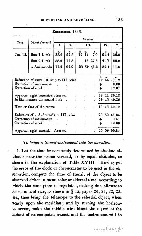
GURVEYINQ AND LEVELLING. 133
To bring a transit-in.strurnent into the meridiaft.
EDINBURGH, 1836.
WIRES. Date. Object observed.
1. Let the time be accurately determined by absolute al- titudes near the prime vertical, or by equal altitudes, as shewn in the explanation of Table XVIII. Having got the error of the clock or chronometer to be used in the ob- servation, compute the time of transit of the object to be observed either in mean solar or sidereal time, according to which the time-piece is regulated, making due allowance for error and rate, as shewn in § 15, 20, 21, 22, 23, kc., then bring the telescope to the celestial object, when nearly upon the meridian; and by turning the horizon- .
tal screw, make the middle wire bisect the object at the instant of its computed transit, and the instrument will be
11.
6i:8
h. m. Reduction of sun's 1st limb to 111. wire . . 19 44 . f i 2 Correction of instrument . . + 0.93 Correction of clock . . + 12.07
Apparent right ascension observed . . 19 44 20.12 In like manner the second limb . . 19 46 40.26
Mean or that of the centre . 19 45 30.19
Reduction of a Andromeda to 111. wire . , 23 69 41.34 Correction of instrument . . + 0.47 Correction of clock . - . . + 12.03
Apparent right ascension observed , . 23 69 66.84
111.
h. rn. 19 44 +:o
46 27.3
23 59 41.3
IV. -- 2;:4
41.7
66.4
V. - 3;:8
65.9
11.6

134 DESCRIPTION OF INSTRUMENTS EMPLOYED IN
in the meridian. Should the object be the sun or moon, either limb must be observed; and, allawing for the time which the semidiameter takes to pass the meridian, that of the.centre becomes known, or the limb, conversely.
Tojind the time that any star takes to pass from one wire to another in a transit-instrument, when that or. the epui- noctial is known.
Rule.-To the log secant of the star's declination, add the logarithm of the time in seconds at the equinoctial, the sun1 will be the logarithm of the time by the star.
Ex. On the 10th of May 1836, the declination of Capella was 45" 49' 32" N., what would be the time of passage of the star from one wire to another, when 'the time upon the equinoctial was 19\64 ?
Declination . 45" 49' 32" N. secant 0.156863 Equinoctial time 1g8.64 log 1.293141
Star's time . 288.18 log 1.450004
This may be readily performed by a Table of Natural Se- cants, like that among my General Tables (XXV.) ; thus, '
19.64 x 1.435 =28".19. Hence the star's expected time of approach to the other wires becomes known after the first contact is observed.
2. To place a transit-instrument in the meridian by Po- laris.
On the 1st of May 1840, let a transit-instrument be placed in the meridian at Edinburgh, in latitude 55" 5'1' 24" N., longitude, in time, 12" 43"s W.
By the Nautical Almanac, the right ascension of Polaris is lh lm 16'.40, and declination 88" 27' 23O.4 N.
Whence, by § 8, page 132.
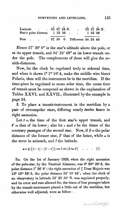
SURVEYING AND LEVEIALLNG. 135
Latitude . . 5 ; 5 $ 2 k N . . 5°55/724N. Star's polar distance 1 32 36 . 1 32 36
Sum . . 57 30 0 Differenra 54 2 4 48
Hence 5'1" 30' 0" is the star's altitude above the pole, or at its upper transit, and 54" 24' 48" at its lower transit un- der the pole. The complements of these will give the ze- nith-distances.
Now, let the clock be regulated truly to sidereal time, and when it shews lh lm 16'.4, make the middle wire bisect Polaris, then will the instrumellt be in the meridian. If the time-piece be regulated to mean solar time, the mean time of transit must be computed as shewn in the explanation of Tables XXVI. and XXVII., illustrate? by the .example in page 24.
3. To place a transitinstrument in the meridian by a pair of circumpolar stars, differing nearly twelve hours in right ascension.
Let t = the time of the first star's upper transit, and t' = that of its lower; also let 4 and ;be the times of the contrary passages of the second star. Now, if 6 = the polar distance of the former star, 6' that of the latter, while a is the error in azimuth, and l the latitude.
Ex. On the 1st of January 1828, when the right ascension of the pole-star, by the Nautical Almanac, was 0'' 59" 28:8, the polar distance 1' 36' 9 ; the right ascension of $ Ursae Majoris was 13h 16" 58?3, the polar distance 34" 10' 4 4 ; when the clock of an obse-matory in latitude 52" 25' 50" N. was regulated properly, and its error and rate allowed for, the times of four passages taken by the transit-instrument placed a little out of the meridian, but otherwise well adjusted, were as follo\v :

h. m. I. h. m r Pole-hr above . 1 0 0.55 = t, below 12 58 66.47 = t'
Ursm Maj. below 1 16 66.46=r, above 13 16 68.16=1 -- t-r . . - 16 64.01 - 18 2.69 t ' - f . . .- 18 2.69
( - ) - ( d ) + 1 7 .78=87' .78=~.
Now, as t'- r', the second interval, exceeds t - r, the first, the deviation is towards the east, while the difference is 6P.78. But, in using formula (I), the error a may be com- puted either in time or arc, as best suits the observer, or the knowledge he h a of the value of a turn of his screws, which he should previously ascertain, at least in an approxi- mate manner. Then, if he wish the correction in time, the constant logarithm will be the arithmetical complement of the log of 2; or 9.698970 ; if in arcs, the log of 9 =7.5, o r 0.8'15061 is the constant.
In Time. 1 . Const. log . . 9.698970
a= lo 36' - 9" sin 8.446619 1=34 10 44 sin 9.749666
1- a= 32 34 35 cosec 0.268876 1=62 25 50 sec 0.214868 A= 67'.78 log 1.831102
7-
a= ls.622 log 0.210000
In Arc. 2. Const. log 0.876061
. 8.446619
. 9.749565
. 0.268876
. 0.214868
. 1.831102
a=24".33 log 1.386091
the respective deviations hi time and arc towards the east. 4. To place a transitinstrument in the meridian by a
>air of high and low stars. If the difference of the right ascensions of two stars, of
which the declinations are 6 and 8, be a, and if a transit- instrument be placed s seconds of time out of the meridian, the interval between their transits will be a + d a seconds of time, and d a may be found from the following formula, in which I is the latitude.

SURVEY INO AND LEVELLING. 137
Let p =D sin (1 - 8) sec 8 . (9 in which 8 is negative when of a contrary name to I, and D the deviation or error in the position of the transit.
Now making n = sin (Z - 8) sec 8 . (4)
then p = n D and p' = D, and hence
Again, let a be the calculated transit or true right ascen- sion of the first star, and t the observed transit, consequent ly p= c- r, and d being the right ascension of the second star p'= u - at, therefore
(t - t) - (a - a') n= n-n' ( 6 )
I f the clock does not keep true time, the interval must be corrected for the rate. Then, if D be popitivi, the instru-' ment deviates to the west; if negative, to the east, and the correction may be made by the divided head of .the adjust ing-screw, while the operation is performed as follows :
Ex. 1. On the 1st of April 1840, the following observations were made in latitude 51" 30' N., and nearly on the meridian of Greenwich.
IL me h h. nL h
Observed tiansit of Regel t = 6 7 31.70 a= 5 6 51.30 ... . . . . . . Capella t' = 5 5 38.08 a' = 5 4 63.08
Whence, to get D, it is only necessary to compute n and d, and, by combining formuh (4) and (6), the vdue of D and D' at the t w o stars will be found.

138 DESCRIPTIOX OF INSTRUMENTS E31PLOYED IN
.?=61°3WN. 6=46 60 N. sec -
2-6= 6 40 sin
n= 0.142 log n'= 0.874
n'-n= 0.732 c~ . c A = - 18.60 log
D= - 0 . 3 1 log
8.9945 2 + C = 59 54 sin 9.9371 --
. . log 9.9418 I . 0.1355 . 0.2041 -
=9.4910 D'= - 1\91 log 0.2814
Here D is negative, and the deviation of the telescope is to- wards the east, but when positive it is to the west.*
See my Rlathematical Tables and General Astronomical Tables on this subject.
Here t - a = . a3.40, and t'- a'= . i5 .00 D' with Cont. sign + 1.91 D with Cont. sign +0.31
7 - Error of clock= . 45.21 fast, or . . 45.31
Or the result may be stated thus : h. m. R. h. m. s.
Capella's R . A. . 5 6 51.30 Rigel's R. A. 5 4 53.08 D ' . - 1.91 D . . - 0.31
-- Time by transit . 6 6 49.39 . , 6 4 52.77 . . . by clock . 5 7 34.70 . . 5 5 38.08
Error of clock fast . 45.31 . . . 45.31 Correction of clock . -45.31 in sidereal time.
If the clock is regulated according to mean time, the in- terval t - P must be, by Table XXVI., converted into side- real.
(a - a' * I f D= )-(t-3, then the sign of D would give the correa- n-n'
tion of the observed time with its proper sign, which would be the con- trary of those stated above.

SURVEYING AND LEVELLING. . 13 9
Ex. 2. On the 24th of April 1828, the following observations were made at Paris on 7 Ursse Majoris above the pole, and on p Cephei under the pole.
h. m. 8. h. m. 8 .
yUrsaeMaj.t=ll 44 13.80, a = l l 4447.10, nl=-0.176 BCephei t'= 9 25 54.80, d= 9 26 24.49, n= +2.642 -
t-t'= 2 18 19.00,a-a'= 2 18 22.61, n'-n= -2.718 a-a'= 2 18 22.61
A = - 3.61 to the right.
Hence making - 3.61 .Z = --- - + ls.33, we have -2.718-
1~ ~ ~ 2 . 5 4 2 x 11.33= + 3R.38, and nlio= -0.176 x ls.33= - 08.23
h. h. m. 8. h. n1. s. Whence to a-12=9 26 24.49, and a l= l l 44 47.10 Apply = + 3.38, and n'x= - 0.23 -- Transit . 9 26 27.87 . , 11 44 46.87
t' . 9 25 54.80 t ' . 11 44 13.80 -- Clock slow of 8. T. 33.07 . 33.07 ,
Remark 1. If, when a circumpolar star is observed be- tween the pole and the zenith of the upper meridian, the same formulas apply, since'n is then negative, because d exceeds I .
2. If the transit is taken between the pole and the hori- zon, the same formulas will still answer, by diminishing the right ascensioii of the star by 12h, and changing the sign of d. The deviation of the telescope pointing to the north is still reckoned to the right, when x is positive; but here this side is found towards the east. The contrary takes place when x is negative. When two circumpolar stars are ob- served, the same remark is applicable to both.
3. When the same star is observed at both passages, sn- perior and inferior, the preceding rule is applicable to both,

the right ascension of the star must be diminished by 12" for the inferior passage, and the sign of d must be changed.
Since the sheet containing page 58 was thrown off, it has been discovered that formula (4) should have been
Sin) H= ( + ( l f s a c ~ , [ s i n @ + ~ , ) s i n @ - D , ) f ) ] i .
By reflecting on the steps of the investigation, it appears that
6. Sin (H - 90") = sec D, {sin (D + D,) sin (D - D,) 1 4 . Because D, is always a small arc, its secant differs little from radius, therefore its effect will be nearly insensible ; hence,
1. H-90°= 2" 7' 42".3 . . . . sine 8.669835 log sec D, . . 0.000051
2. H-90°=2"7'43".2 . . . . . 8.569886
The second value, therefore, exceeds the first by 1" only, a difference of little consequence in this problem.

EXPLANATION OF THE TABLES.
TABLE I . Depression or Dip of the Horizon.
The dip of the horizon is the angle contained between a line perpendicular to the plumb-line, passing through the eye of the observer, elevated above the level of the se% and a line from his eye to the visible horizon when they are in the same vertical plane. This table contains the apparent dip answering to a free unobstructed horizon, diminished by 0.08 of itself, or of the intercepted arc for the effects of re- fraction.
1. The numbers in the table corresponding to the height of the eye of the observer, is to be d t rac ted from the ob- served altitude when taken by the fore observation with Hadley's quadrant and similar instruments, but added to it in m e the altitude be taken by the back observation.
2. This has been the principal use to which analogous tables have hitherto been applied, but it may be often ad- vantageously employed for other purposes, which has been an inducement to extend it a little beyond the usual limits. Since the true dip has been diminished by 0.08 or about & of itself to reduce it to the amarent, it consequently follows that if the apparent dip be increased by double of 0.08, or 0.16, equal to of itself nearly, the result will be the distance of the visible horizon in geographical miles.
3. If the a2?parentdip be measured with a good theodolite or astronomical circle, the corresponding height of the in-

142 - EXPLANATION OF THE TABLES.
strument above the sea, will be found by the table with as
much accuracy as the nature of the horizontal refraction /will admit.
EXAMPLES.-1. TO the height of the eye, 16 feet in the first column, will be found 3' 56, the dip in the second.
2. To the height of the eye, 500 feet,
there will be found . . 22' To this add & of itself . 3;
- Sum or distance of the horizon . = 25% miles.
3. From a point on Inchcolm the author observed the depres- sion of the horizon of the sea down the Firth of Forth to be
8' 21."2; required the height of the instrument above the sea?
By the table to dip . = 8' 14" the height is 70 feet. Proportional part to . 7.2 . + 2.1 feet.
Height of instrument for . 8 21.2 = 72.1 feet.
TABLE 11. Correction bf the Apparent Altitudes of the Sun and Stars.
I n this table the altitude is found in the first column, the star's correction or mean refraction in the second, and the difference between the mean refraction and the sun's meall parallax, constituting the sun's correction in the third.
EXAMPLES.-1. Required the correction of the altitude of a star which was observed to be 22" 30'1
2. Required the sun's correction at an altitude of 31" 20'1
These are tlie true corrections wllen the English baro- meter stands at 30 inches, and Fahrenheit's thermometer :tt 50°, and are always to he subtracted from the apparent

EXPLANATION OF THE TABLES. 143
altitude or added to the apparent zenith distance to obtain the true.
TABLE 111. To correct the Mea~r Refraction.
When the barometer differs from 30 inches, and the ther- mometer from 50°, the mean corrections, a.s above, may be reduced for the effects of pressure and temperature by this table with sufficient accuracy, when altitudes are taken with the ordinary theodolite or sextant. These corrections must be applied according to the signs in the table. Thus, in the first example to the preceding table, let the observed height of the barometer b=2gn.57, and the temperature by Fahrenheit's thermometer t= 86, then
To the mean refraction formerly found . 2' 2W There must be applied for the altitude 22" 30', and b = 2gh.57 - 2 For altitude 22" 30', and t=84" - 10 -
True refraction . . 2 8
or the star's correction to be subtracted. I11 like manner for the second example,
To the mean correction . . it 36".3 For altitude 31' 20', and b=30ir28 . . + , 1 . 0 For altitude 31 20 and t= 30' Fahrenheit . $. 4 . 0
The sun's true correction . . 1 41 .3
and so on in similar cases.
TABLE IV. Correction of the Apparent Altitude of the Moon.
This table contains the difference between the moon's par- allax in altitude and the mean refraction, and must be al- ways added to the apparent altitude to obtain the time. To the moon's apparent altitude in the first column on the left, and under the minutes in the moon's horizontal parallax at the cop, will be found the correction for the nearest less de- gree of altitude and minute of parallax ; and the propor-

144 EXPLANATION OF THE TABLES.
tional parts for minutes of. altitude and seconds of parallax, are found in the two adjacent right hand columns, taking care not to neglect the parts to o' of altitude, as for the sake of the convenience of having all the parts additive, the con- struction of the table requires.
EXAMPLE 1.-Let the moon's apparent altitude be 32" 40'' and the equatorial horizontal parallax 58' 32" ; required the true cor- rection when the barometer stood at 29.6 inches, and Fahren- heit's thermometer at 72" ?
To app. altitude 32' and horizontal parallax 58' correc. . + 47' 10" To app. altitude 0' 40' proportional parts . + 10 To seconds of parallax 3 2 . . + 27 -
True correction for b = 30°, and t = 60" . 47 47 To b = 2gh.6 and altitude 32" 40' correction . + 1 To t=72' and altitude 32' 40' correction + 4 -
True correction . 47 52
for real temperature and pressure, where, according to the remark at the foot of Table 111, the corrections depending upon b and t have been applied with signs contrary to those marked in the table.
TABLE V. Mean Refractions.
This table contains the logarithms of the mean refrac- tions at 30 inches of the English barometer, and 50" of Fah- renheit's thermometer. I t is succeeded by Tables VI.,VII., VIII., IX., and X., to reduce it to any other pressure and temperature, either for the English barometer and Fahren- heit's thermometer by the first three auxiliary tables, or for the metrical barometer and centigrade thermometer by the two last, in which the logarithms for rand t are, as is f r e quently the ease, united in one with the argument t, a'me- thod that in general cannot sensibly affect the accuracy of

EXPLANATION OP THE TABLEE;. 145
the results. Logarithmic tables of refraction are used by all astroilomers where extreme precision, combined with facility of calculation, are required.
EXAMPLES-1. Let the zenith-distance B be 68" 55' 36, the ba- rometer b=28.80 inches, and the thermometers r and t each 65" Fahrenheit ; required the refraction ?
For 4 = 68' 40' log 1 8 . 2.17171 Prop. part for 15.6=37.1 x 15.6= , . + 579
b = 28h.80 log (Table VI.) . 9.98227 r = 65" . log (Table VII.) . 9.99936 t = 65' . log (Table VIII.) . 9.98663
r E 2' 19.87 = 13W.87 . . log 2.14675
2. Let t7= 87" 42' lo", b= 2gh.50, r and t= 35" ; required r, the refraction ?
For$ = 87'40' O"1ogdb . 3.00522 Prop. parts for 2 10 392
b = 2gh.5O . log aa before . 9.99270 r = 36" . . log 0.00065 t = 36" . . log 0.01379
,," = . 1038.20 log 3.01628
~ x ( 3 5 " - 5 0 ' ) = - U ' . 5 9 1 ~ d r -16" = . + 8.86
r= . . 1046.64 = 17' 26".54 r as observed by Brinkley . . 17 26.50
Difference between theory and observation . + 0.04
3. Let 8=88" 24 9.7, the metrical barometer b=755 milli- metres, and r and t each F.75 centigrade ; requird the refrac tion ?
$ = 88" 24' W.7 log d d - . 3.08937 b = 755mm log (Table IX.) . . 9.99599 t = 8O.75 cent. log(Tab1eX.) . . 0.00216
l . ~ . 1223.23 log 3.08752

146 EXPLANATION OF THE TABLES.
1223".23 log 3.08752
dd( x (8O.76- 10°)=Uf~O1 x -1.26 x 1.8 = +2.05 d r
T = 1225.00= 20' 25".00 T from observation by Plana . . 20 24 .30
Difference of theory from observation . . + 0 . 7 0
From these instances it is evident that the table gives the value of the refraction with great accuracy. It must be added to the zenith distance and subtracted from the alti- tude. The reason that the first small correction of r is multiplied by 1°.8 is, that lo centigrade is equal to 1°.8 Fahrenheit, that to which the corrections in the table are adapted, 'and as 39'".371 are equal to a' metre, the second must be divided by this or even by 40, as sufficiently accurate.
TABLE XI. Logarithms to compute the value of the Coe$cient of Terrestrid Refraction.
I n the practice of Trigonometrical'Levelling it is of the utmost impor&nce to get the value of terrestrial refraction truly. Hitherto it has generally been the practice to d e termine occasionally from numerous observations, its mean value by reciprocal and simultaneous measures, and to em- ploy it either exactly as obtained, or under assumed varia- tions in all cases. Reflecting on the inaccuracy of this plan, I endeavoured to investigate .a formula which would give, with as much precision as the nature-of the case seemed to admit, the value of the coefficient of terrestrial refrac- tion, and from which the present table has been derived."
EXAMPLE.-L~~ the barometer b =29.75 inches, the attached
* See the Edinburgh New Pbilosophical Journal for April 1841.

EXPLANATION OF THE TABLES. 147
thermometer r= 64", and the detached t =64" Fahrenheit ; re- quired n the coefficient of refraction ? For b = 29in.75 and t = 64' (Table XI.) . log 7.44997
r = 64" log (Table VII.) 9.99940 t = 64" log x 2 (Table VIII.) . 9.97602 b = 29.76log . 1.47349
n = 0.07906 log 8.89788
TABLE XII. ParaUaz of the Sun in Altitude or Zenith Distance.
The parallax of the sun on the first day of each month at the top, and to every third degree of altitude in the left hand column, or zenith distance on the right, will be obtained from this table by inspection, and for any intermediate day or degree it may be readily found by interpolation, as will be subsequently exemplified.
TABLE XIII. Parallax of the Planets in Altitude or Zenith Distance.
This is precisely similar to the last, and is used in the same manner.
E W P L ~ Required the parallax of Venus st an pltitude of 30" on the 1st of December 1840, when the horizontal paranax was 12.6 ?
To altitude 36 and paral4x . 16. 8.7 30 . . . . . . 2. 1.7
. . . . . . 30 0.6 0.5 - - To altitude 30 and horizontal parallax 12.6 10.9
Hence the parallax in altitude is found to be 10".9.
TABLE XIV. Augmentation of the Moon'd Semidiamter in Altitude or Zenith-Distance.
With the moon's semidiameter at the top, and altitude on the left, or zenith-distance on the right-hand column, will be found the augmentation to be added to the semi- diameter on that account.

148 EXPLANATION OF THE TABLES.
TABLE XV. Reduction of the Moon's Parallax on the Spheroid.
With the moon's quatorial horizontal parallax at the top, and the latitude on the lefthand column, the reduction to be subtr&ted from the moon's equatorial horizontal pa^
rallax, to reduce it to the given latitude, will be found.
TABLE XVI. Reduction of the Latitude on the Spheroid.
With the observed latitude on the left, the reduction mi11 be found on the right, to be subtracted from the observed latitude, to get the reduced latitude, or that referred to the centre of the e+h, considered as a spheroid of & of compression.
TABLE XVII. Reduction to the Meridian.
The method of determining the latitude by repeated ob- servations near the meridian, makes the smaller classes of instruments much more efficient than they otherwise would be. Indeed it renders them much more nearly equal to the larger classes of instruments, such as the mural circles, than could have been anticipated. There are various me- thods of accomplishing this. In many cases the numbers in the table are given in seconds of arc and decimals, in others they are merely versines. The late Dr Thomas Young Grst gave, I believe, a small table of versines for this purpose, similar to ours. I have, however, extended the numbers in the column titled V to one place more than his, which includes quantities to the first order only. To this I have added another column v, entirely omitted in Young's, embracing quantities to the second order in the formula, which cannot be dispensed with when the zenith- distance is small, not greater than about lo0, and the time extending to about ten minutes from the meridian, &c.
In this way the numbers are all integers, which, by those
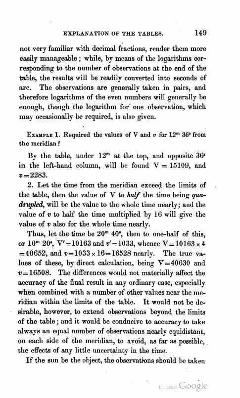
EXPLANATION OF THE TABLES. 149
not very familiar with decimal fractions, render them more easily manageable ; while, by means of the logarithms cor- responding to the number of observations a t the end of the table, the results will be readily converted into seconds of arc. The observations are generally taken in pairs, and therefore logarithms of the even numbers will generally be enough, though the logarithm for' one observation, which may occasionally be required, is also given.
EXAMPLE 1. Required the values of V and v for 12" 36"rom the meridian ?
By the table, under 12" a t the top, and opposite 368 in the left-hand column, will be found V = 15109, and v = 2283.
2. Let the time from the meridian exceed the limits of t he table, then the value of V to h a y the time being qua- drupled, will be the value to the whole time nearly; and the value of v to half the time multiplied by 16 will give the value of v also f i r the whole time nearly.
Thus, let the time be 20" 4OS, then to one-half of this, or 10" 20; v'=10163 and v'= 1033, whence V= 10163 x 4 4 0 6 5 2 , and v=1033 x 16= 16528 nearly. The true v+ lues of these, by direct calculation, being V=40630 and v= 16508. The differences would not materially affect the accuracy of the final result in any ordinary case, especially when combined with a number of other values near the me- ridian within the limits of the table. It would not be d e sirable, however, to extend observations beyond the limits of the table ; and i t would be conducive to accuracy to take always an equal number of observations nearly equidistant, on each side of the meridian, to avoid, as far as possible,, the effects of any little uncertainty in the time.
I f the sun be the object, the observations shoulh be bken

160 EXPLANATION OF THE TABLES.
by a watch shewing mean shim time,--if a star, by a watch shewing sidereal time.
If the sun be the.object, and the watch regulated to side- real time, V must be multiplied by 0.9945466, the square of the number to convert sidereal into mean solar time, of which the logarithm is 9.997625 ; and if the watch be re- gulated to mean solar time when a star ie observed, V must be multiplied by 1.0054833, of which the log is 0.0023'75, to convert the effect from mean solar into that from side- real time.
When the watch does not go accurately to either times, thevalueof Vmust be further multiplied by 1 + 0.00002315r, whose log is 0.000010053 r, in which r is the rate of the watch, reckoned PLUS when LOSING, and minus whengaiw ing. When r is negative, the arithmetical complement of the log denotedmby 0.000010053 r must be taken.
If these rates be small, and the distance from the meri- dian moderate, their effects will hardly be sensible.
When the zenithdistance exceeds 30°, the first tema of formula (6), page 18, will be sufficient ; and if the object is below the pole, the reduction must be applied with a contrary sign.
On applying this table in formula (11) and (12), page 32, d 1 is positive when the star is above the pole, negative when below it ; dm is positive when the star is in the semicircle farthest from the referring lamp or staff, negative when nearest. Consequently, in page 33, line 12 from the bob tom, the reduction to the centre was really -33".18, but to render d m positive, so that all the columns might be added, the double of -1".26, the mean of these, or -2If.52, was added to - 33".18, making it - 35".10, which artifices are admissible, at the option of the computer, when they con- duce to facility or wnvenience.

EXPLANATION OF THE TABLES. 151
TABLE XVIII . Logarithms to compute the Equation to Eqwk ~ltittuim and &wI Azimuth.
The first column in this table contains the elapsed time between the observations, and is the common argument to the other three columns A, B, C. The two first, A and B, are employed to compute the equation to equal altitudes in seconds of time, and C to compute the equation to equal azimuths in seconds of arc.
The computation of the equation to equal altitudes is performed by the following rules.
1. To the log A, from Table XVIII., add the log tan- gent of the latitude, the log of the hourly variation of the sun's declination from the Nautical Almanac, to be marked positive, or +, when the polar distance is increasing, and negative, or -, when decreasing ; the sum of these three logarithms will be the log of part fir& of the equation. for noon. The signs must be reversed for midnight.
2. To log B add the log tangent of the declination to be reckoned positive, if the polar distance is less than 90°, but negative, if greater; and the log of the sun's hourly v& tion reckoned positive, if the polar distance is decreasing, but negative, if increasing; the sum will be the log of the secwd part of the equation for noon or midnight.
3. To the log C, from Table XVIII., add the log cose- cant of the latitude, and the log of the sun's hourly motion from the Nautical Alrhanac, the sulll will be the equation to equal azimuths, in seconds of arc, to be allowed to the left of the meridian indicated on the horizontal circle for the noon of the same day, when the polar distance is de- creasing,: but to the right if increasing. The signs must be reversed for midnight, or the correction for the meridian must be allowed to the right when the polar distance is de- creasing, but to the left when increasing.

152 EXPLANAT.ION OF THE TABLES.
EXAMPLB 1. At Madeira, in latitude 32" 38' 26" N., longitude lb 7m 358 W., on the 8th of August 1840, at gh 55m 348.2 fore- noon, and 4h 26m 268.5'afternoon, by chronometer, the sun had equal altitudes ; required the time of apparent noon ?
LogA . . +9.4699 Log B . t-9.2779 Lat. 32" 38'.4 N. tan + 9.8065 Dec. 16" 4' N. tan + 9.4594 ad= +43".17 log + 1.6352 . . - 1.6352
1st part + TR.97 log + 0.901 6. 2d part= - 28.36 log -0.3725 2d part - 2 .36 - E. E. A. + 6.61 + 13h 1 lm 0\35 - 12h. (App. noon) lh llm 6#.99
2. At the same plabe in August 1840.
August 8th, P. M. and August gth, A. M.
Equation to equal altitudes for Midnight. Log A , . +9.8895 Log B . . -9.7082 Lat. 32" 38'.4 N. tan + 9.8065 Dec. 15" 56' N. . + 9.4556 ad= -43.45 log -1.6380 . . -1.6380
1st term-21\58 log - 1.3340 2d term + 6s.34 log + 0.8018 2d term + 6 .34
E. E.A. - 15.24+ 13h 14m 478.00-12h (Midn.)=lh 11" 318.76
3. On the 28th of February 1840, in latitude 55" 57' N., lon- gitude 12"' 43.5 W., in an intervd of 5h 30" Oq, the sun had equal altitudes when the azimuth circle read 130" 10' 15" and 32" 36' 15", and consequently the middle point = 4 (130" 10' 1 5 + 32'36' 1 5 ) = 81" 23' 1 5 ; required the true meridian point 1
To interval 5h 30m O8 log C . . 0.6202 Latitude 55' 57' N. log secant . 0.2519 B d= 56".69 log . . 1.7535 . 1':. E. Az. 7' Y . 3 = 4 2 2 . 3 log 2.6256

EXPLANATION OF THE TABLES. 153
Hence if from . . ti1 2'3 <5.0 There be subtracted . '- 7 2.3
The remainder . 81 16 12.7
is the reading of the instrument when set to the true meri- dian.
TABLE XIX. Logarithms to convert Feet on the Surface of the Terre8triaZ Spheroicl into Seconds of Arc, and conversely.
This table, of great use in Trigonometrical Surveying, contains the logarithms of the reciprocals of the radii of curvature in ally given direction multiplied by the arc, equal to the radius in seconds. Log M are those on the meri- dian, Log P those on an arc perpendicular to the meridian, and Log 0 those in any direction indicated by the azi- muth a or Z. The differences for each degree in M and P are given, to interpolate more easily for minutes of lati- tude.
EXAMPLES. Required the log M forlatitude 51" 13.5, the log P for 50" 58.3, and the log 0 for latitude 66" 4.5, and a or Z = S. 106" 46.4 W.
1. To latitude 61" (Y log M . 7.9940850 Prop. parts for 13.6 . . - 167
Log M to latitude 61" 13'.5 . 7.9940683
2. To latitude 50" 0' log P . . 7.9929588 Prop. part to 58.3 . - 241
Log P to latitude 50' 58'.3 . . . 7.9929347
3. To lat. 56" and Z = 100" log 0 . 7.9928406 Prop. parts to 4'.5 of latitude . . - 19 Prop. parts to 6O.8 of azimuth . . + 636
Log 0 to lat. 66" 4l.5 and Z + 106" 46l.4 7.9928922
The numbers from Tables XX. and XXI. are taken out in t6e same manner.

154 EXPLANATION OF THE TABLEK.
TABLE XXII. Reduction of A to I.
This table, computed from the formula pN94 sin 1" tan A, in which X is the latitude of the foot of the perpendicular arc from the given station on the meridian passing through that required, and pN the length of that arc itself in seconds of arc, gives to X at the top of the page, and p' in the left- hand column, in minutes, a small correction within its limits to be subtracted from X to give 1, the true latitude of the required point, derived trigonometrically from the first. If the quantity is not got at sight, it may be easily found by interpolation.
TABLE XXIII.
This table is the same in principle as the last, but ex- tended to every degree through the British Islands, for the purpose of facilitating calculations made within its range.
EXAMPLE. Required the reduction of a to Z, when ?.=57" 51' 4.5", and p"= 24' 3 6 ?
a = 57" and p" = 24' g h e . -7 .73 Prop. parts for 61' of h . . -0 .27
. . . for 36" of p" . . -0.40 .
Sum . . -8 .40 a . 670 51' 4.60
1 the true latitude . . 67 60 66 .10
TABLE XXIV. TO-reduce a Base at the level of the Sea to any height above it, or from any height above the Sea to its level..
EXAMPLE 1. Required the length of the chord K, when the arc a is 164045 feet, and height above the sea h=6662 feet? Log a . $6.1149630 For h= 6000 feet, into . +0.0001246
600 . . + 1 0 4 62 . . + 13
For a = 100000 feet, p a* . . - 4 64000 ft.a, + 0.61 -Eq. A,= - 13 $. 0.64 - 1 = - 7
Log K a t the height h . 6.2160982

EXPLANATION OF THE TABLES. 155
2. The base, on Hounslow-Heath, was found to be by ROY . 27404.0843 feet. Mudge . . 27404.3166 -- Mean . . 27404.1999
Log of this . . 4.4378172 For h= 54 feet above the sea . - 11 For a = 27404.2 feet, p aa . + 0
Log K at the level of the sea . . 4.4378161
This table, therefore, serves to reduce bases from the level of the sea to great heights, for the purpose of accu- rate trigonometrical levelling, or for reducing a measured base to the level of the sea, in order to extend a series of triangles at that level over a tract of country.
TABLE XXV. The m e w r e of one Minute of Arc in feet at each degree of latitude.
As the latitudes and longitudes of a number of places throughout the British Isles will shortly be made known in the volumes of the Trigonometrical Survey, then, by taking a few angles, and either measuring a base carefully, or, if pssible, selecting a distance from the survey, the position of any particular point at a moderate distance may be readily fixed by means of this table.
EXAMPLE. In the Island of Iona, Carn Cul ri Eirn is south of Carn Dunii 9955 feet, and west of it 8111 feet; required the la- titude and longitude of Carn Cul ri Eirn, those of Dunii being 56" 20' 33" N., longitude 6" 23' 36" W. ?
By the table, 1' of latitude at 56".20'is 6087.2 feet, there- fore 9955 +6087.2 = 1'.65 = I' 39" S. Hence 56" 20' 33'- 1' 3Y'=56" 18' 54" N., the latitude of Carn Cul ri Eirn.
In like manner, the length of a minute of longitude is 3381.3 feet; hence 8111+3381.3=2'.4=2' 24", therefore
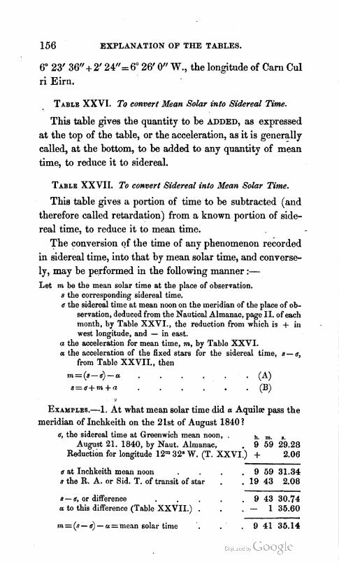
156 EXPLANATION OF THE TABLES.
6" 23' 36" + 2' 24"= 6" 26' 0" W., the longitude of Carn Cul ri Eirn.
TABLE XXVI. To convert Mean Solar into Sidereal Time.
This table gives the quantity to be ADDED, as expressed at the top of the table, or the acceleration, as it is generally called, at the bottom, to be added to any quantity of mean time, to red~zce it to sidereal.
TABLE XXVII. To convert Sidereal into Meala Solar Time.
This table gives a portion of time to be subtracted (and therefore called retardation) from a known portion of side- real time, to reduce it to mean time.
The conversion of the time of any phenomenon recorded in sidereal time, into that by mean solar time, and converse- ly, may be performed in the following manner :- Let m be the mean solar time a t the place of observation.
s the corresponding sidereal time. a the sidereal time a t mean noon on the meridian of the place of ob-
servation, deduced from the Nautical Almanac, page 11. of each month, by Table XXVI. , the reduction from which is + in west longitude, and - in east.
a the acceleration for mean time, m, by Table XXVI. a the acceleration of the fixed stars for the sidereal time, s- a,
from Table XXVII . , then
m=(s-6)-a . - (A) s = a + m + n . (B)
EXAMPLES.-1. At what mean solar time did a Aquil~ pass the meridian of lnchkeith on the 21st of August 18401
a, the sidereal time a t Greenwich mean noon, . h. m. B.
August 21. 1840, by Naut. Almanac, 9 59 29.28 Reduotion for longitude 12m 328 W. (T. XXVI:) + 2.06
a at Inchkeith mean noon . 9 59 31.34 s the R. A. or Sid. T. of transit of star . . 19 43 2.08
8 - a, or difference , 9 43 30.74 a to this difference (Table XXVII . ) . - 1 35.60 --
m=(s-a) - ~ = m e a n solar time '. . 9 41 35.14
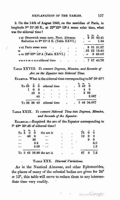
EXPLANATION OF THE TABLES. 157
2. On the 14th of August 1840, on the meridian of Paris, in longitude 9" 21\33 E., at 22"'22" 13'.4 mean solar time, what was the sidereal time ?
h. m. 8.
u at Gteenwich mean noon, Naut. Almanac . 9 31 63.41 Reduction to grn 21s.3 E. (Table XXVI.) . - 1.54
u at Paris mean noon - . . 9 31 51.87 na . .22 22 13.40 a t, 22b'22rn i30.4 i ~ a b l e XXSI.) , + 3 40.49
s=u+ m + a=sidereal time . . '7 67 46.76
TABLE XXVIII. To convert Degrees, Minutes, and Seconds of Arc on the Equator into Sidereal Time.
EXAMPLE. What is the sidereal time corresponding to 56" 38'401 h. m.
To 6°5 6 6 sidereal time . . 3 4 0 5 1 0 0 . 4 0
38 0 . 2 32 40 . 2.667
To 66 38 40 sidereal time . . 3 46 34.667
TABLE XXIX. To convert Sidered Time into Degrees, Minutes, and Seconds of the Eguatm.
EXAXPLE.-Required the arc of the Equator corresponding to 48m 36O.48 of sidereal time ?
h. m. TO 5 o 6 the arc is f i 6 6
48 0 . . . 12 . 0 0 ... 36 . . . 9 0 . . . 0.4 6.0 ... 0.08 . ... 1.2
To 5 48 36.48 the arc is 87 9 7.2
TABLE XXX. Diurnal Variations.
As in the Nautical Almanac, and other Ephemerides, the places of many of the celestial bodies are given for 24h or 12h, this table will serve to reduce them to ally interme- diate time very readily. '
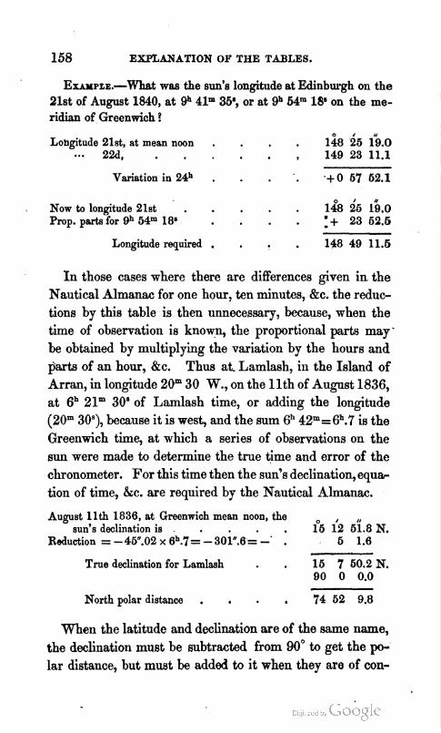
158 EXPLANATION OF THE TABLES.
Exrn~~~. -What was the sun's longitude at Edinburgh on the 21st of August 1840, at gh 41m 3P, or at gh 64" 18' on the me- ridian of Greenwich ?
Longitude 21st, at mean noon . . 148 i5 15.0 22d, , 149 23 11.1
Variation in 24h . . .+06762.1
Now to longitude 21st . . 1 4 8 i 5 5 6 . 0 Prop. pruts for gh 54" 18' :+ 23 62.6
Longitude required . . 148 49 11 .6
I n those cases where there are differences given in the Nautical Almanac for one hour, ten minutes, kc. the reduc- tions by this table is then unnecessary, because, when the time of observation is knowp, the proportional parts may ' be obtained by multiplying the variation by the hours and parts of an hour, &c. Thus at. Lamlash, i11 the Island of Arran, in longitude 20" 30 W., on the l l t h of August 1836, at 6h 21m 30' of Lamlash time, or adding the longitude (20" 309, because it is west, and the sum 6h 42m=6h.7 is the Greenwich time, at which a series of observations on the sun were made to determine the true time and error of the chronometer. For this time then the sun's declination, equ* tion of time, &c. are required by the Nautical Almanac.
August llth 1836, at Greenwich mean noon, the sun's declination is . . . 106 i2 5T.8 N.
Reduction = - 4W.02 x 6h.7 = - 301".6 = -' . 6 1.6
True declination for Lamlash . 15 7 60.2 N. 90 0 0.0
North polar distance . . 74 52 9.8
When the latitude and declination are of the same name, the declination must be subtracted from 90" to get the po- lar distance, but must be added to it when they are of con-
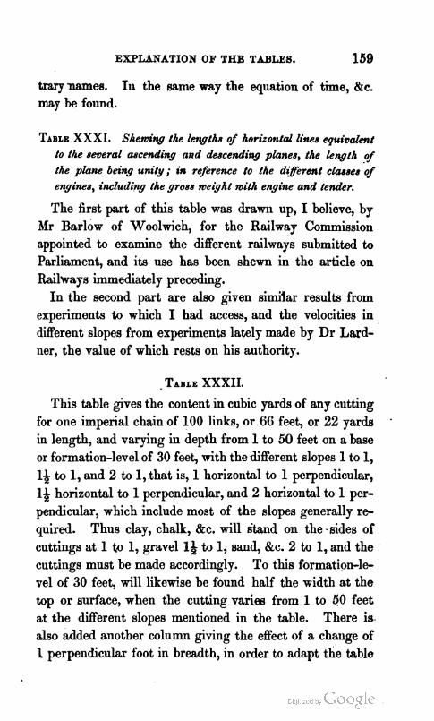
EXPLANATION OF THE TABLES. 159
trary names. In the same way the equation of time, k c . may be found.
TABLE XXXI. Shewing the lengths o f honiontal lines e q u i v h t to the several ascending and descending planes, the length o f the plane being unity; in reference to the darerent classes of engines, including the gross weQht with engine and tender.
The first part of this table was drawn up, I believe, by Mr Barlow of Woolwich, for the Railway Commission appointed to examine the different railways submitted to Parliament, and its use has been shewn in the article on Railways immediately preceding.
In the second part are also given similar results from experiments to which I had access, and the velocities in different slopes from experiments lately made by Dr Lard- ner, the value of which rests on his authority.
- TABLE XXXII.
This table gives the content in cubic yards of any cutting for one imperial chain of 100 links, or 66 feet, or 22 yards .
in length, and varying in depth from 1 to 50 feet on a base or formation-level of 30 feet, with the different slopes 1 to 1, l+ to 1, and 2 to 1, that is, 1 horizontal to 1 perpendicular, 1+ horizontal to 1 perpendicular, and 2 horizontal to 1 per- pendicular, which include most of the slopes generally re- quired. Thus clay, chalk, &c. will &and on the-sides of cuttings at 1 to 1, gravel la to 1, sand, &c. 2 to 1, and the cuttings must be made accordingly. To this formation-le- vel of 30 feet, will likewise be found half the width at the top or surface, when the cutting varies from 1 to $0 feet at the different slopes mentioned in the table. There is also added another column giving the effect of a change of 1 perpei~dicular foot in breadth, in order to adapt the table

160 EXPLANATION OF THE TABLES.
to different bases either above or below 30 feet. If the base exceed 30, the number of yards in this column, mul- tiplied by the number of feet greater than 30, gives a COT-
rection to be added to the content from the preceding co- lumn, but to be subtracted if less. The half-width must also be corrected by increasing or diminishing the change made on the base, in the ratio of the slopes.
If the length of the cutting differ from one chain, the number from the table must be multiplied by the number of chains considered an integer, and the links a decimal, the product will be the content in cubic yards. This table is computed on the supposition that the depth is uniform, or nearly so, in'each portion for which the calculation is made. If it varies rapidly, the portions to which it is ap- plied must be diminished to a few links. In this manner. the table will suit most ordinary cases likely to occur. If not, then Mr Macniell's tables must be applied, which are well adapted to all sorts of cuttingsp but are unfortunately rather expensive for common use.
Though the slopes in the table are those most commonly used, yet they may sometimes fall between or beyond them. Then to the width at the base in feet, add the horizontal length of the side of the triangle formed by the slope, mul- tiply the sum by the depth of the cutting, and also by the length, all in feet, the product divided by 27, will give the content in cubic yards.
I t is to be remarked that the depth, multiplied by the slope, gives the side of the triangle to be added to the base, to give the mean breadth, which, multiplied by the depth, gives the area of the section, and this by the length to give .the content of the cutting.
EXAMPLES-1. Let the length of a cutting be 3.75 chains, the

EXPLANATION OF THE TABLES. 161
depth 40 feet, t.he base or formation-level 30 feet, with slopes 1& to 1, there will be found in the table 8800 cubic feet for 1 chain.
Therefore 8800 x 3.75 =33000 cubic yards, the quantity of cutting ,
required.
2. For a height or depth of 40, and a base likewise of 40 feet, multiply the number under content for 1 perpendicular foot in breadth by 10, the product will be the number of cubic yards to be added to the number for 30 in the table, to give that for 40 feet of base, thus :-
8800.00 + 10 x 97.77 = 8800.00 + 977.7 ~ 9 7 7 7 . 7 cubic yards for 1 chain.
This last, multiplied by the length 3.76 chains, will give
9777.7 x 3.75= 30666.37 cubic yards.
3. To compute the content for 1 chain in length for slopes not given in the table, suppose we have a cutting with a width of base or formation-level of 28 feet and a depth of 16 feet, the sides
of which have a slope of 1) to 1, then by the directions previously given
( 1 6 ~ 1 ~ + 2 8 ) x l G = ( 2 0 + 2 8 ) x 1 6 = ' i G 8
square feet, the area of the section. Then this area, rnultiplicd by the length in feet, and the product divided by 27, mill give the content of the cutting in cubic yards. For one chain of 66 feet this will be
7 6 8 ~ 6 6 = 2 6 6 ~ 2 2 - -- 27 - 1877; cubic yards.
The same process may be followed for any section long or short, which may be made to vary according to the change of the configuration of the ground.
ERRATA.
Pnge 3, line 3 from bottom, for Connaisnnce read Connaissnncc 36, line i from top, for elliptic all^ read ellipticity - 47. mote, for log p" and 2 read log p"X 2 , 68. for sin f H, Qc. see page 110
I,


ASTRONOMICAL,
GEODETICAL, AND RAILWAY
TABLES.

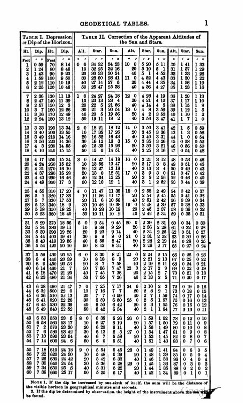
GEODETICAL TABLES. 1

2 GEODETICAL TABLES.
The signs must he chaoged when tile numbers from this Table nre applied to the correction I
of the BIoon's AltituAe.
TAI?LE 11.. Correction of the Apparent Altituclr of the hioon.
1's hloon'a Norizontnl Pnmllnx.
0 # ! , t , , , , , ,,, , r , ,,, , , , , ! I
- 0 1 9 2 8 2 0 2 8 2 1 2 8 ~ ~ B 2 3 2 4 . 1 2 2 5 2 8 2 6 2 8 0 1 89 33 30 33 31 39 32 33 33 33 31 3'3 35 33 .% 33 10 2 35 37 36 37 37 37 38 37 39 37 .;D 37 41 37 +3 37 90 3 3! 30 40 30 41 30 42 29 43 29 4.1 29 45 S 4,; 21; 33 4 4" 4.3 G 41 6 .:a 6 dli 5 47 5 LS 3 49 5 4 0 6 43 65 44 55 45 54 :ti 54 47 54 4s 54 19 53 50 53 60 - 6 45 13 46 12 47 12 48 11 49 11 50 10 51 10 52 10 0 1 46 10 .ti 10 48 n .In 9 50 9 51 s sz 7 53 7 10 8 46 54 47 53 44 62 49 52 30 51 51 51 52 50 53 50 20 9 47 26 45 1 ; 49 25 ;I) 24 :;l 23 5223 53 2" 54 2l 30
14 48 35 -19 33 50 31 51 3n 6.2 28 53 26 54 24 55 22 20 2 2 2 2 2 19 21 23 25 57 16 48 36 49 3-1 50 32 51 3 3 52 28 53 26 54 24 55 22 330 3 3 3 3 3 29 31 3.5 37 16 48 35 I9 32 .iO 30 51 29 50 "i 53 23 34 21 53 2(l -10 3 3 4 4 4 3!3 41 &> -1.5 49i 17 48 31 49 28 50 26 51 23 52 20 53 18 54 15 53 13 30 4 4 5 5 5 4P 50 52 51 56
-- -- ---- ----- 18 48 17 49 12 50 10 51 7 .52 4 W 0 59 57 21 54 0 14 13 13 13 12 0 2 4 6 7 19 43 7 49 ., 49 59 $3 ,% 51 52 32 49 53 45 54 41 10 12 11 11 lo 10 9 11 13 15 17 LO 47 56 .&8 61 49 $7 50 43 51 39 52 3.5 53 31 54 27 20 2 9 8 8 7 19 91 '72 24 26 21 47 42 4P 37 4!3 3.7 50 :El 51 24 52 !?O 53 16 5i 11 .;0 r 6 6 $ 5 28 3') 32 34135 "2 47?74S2?491i5012,j1 853 3225S.735.340 5 4 4 0 3::173941 13143
25 46 34 47 22 48 22 49 16 54 10 51 4 51 58 5.2 W2 10 19 18 18 17 16 9 11 13 14 I6 'I6 46 14 47 I 48 1 4% 64 49 48 50 41 51 35 52 22 20 15 15 1.4 13 12 18 20 22 23 05 27 45 5246 45 47 38 45 31 49 24 50 17 51 10 42 .> .W 11 11 10 9 S 27 29 30 32 3.4 2'1 4.5 30 46 22 47 15 48 7 .19 0 49 8" 50 51 37 413 8 7 6 5 -5.36 39 33 41 13
) 3 8 6 43 68 46 W,O 42 48 34 49 26 51) 18 50 l(l/50 4 ' 3 -4 b l 1 - l l.LF 47 4SliOli2

GEODETICAL TABLES. 3
TABLE IV. Correction of the Apparent Altitude of the Moon.
0
31 32
37
41
44
3Ioon's IIorixmtnl Pnwllnx. P. P. for Alt.+ P . P . for Pnr.1-
A 0' 2' 4' 6' 8' CYf 2' 4" G' 8
5
18 24 31 37
4 9 1 0
16
2.5126
, ,/
3 0 4 4 4 1 44 1.5 43 48
~ 4 3 2 1 3 4 4 2 5 2 4 3 4 1
10 20
2 5 0
4 4 5 6 4 0 1 2 1 1 1 0 50
50 51 52 53 - 54
55
58
69'
# t,
48 30 48 0
4 2 3 8 2 8 3 9 1 2 g 1 3 7 5 i
473516
7 14 20 27 33
1 7
12
23
r,
25 20
5
6
2 2 8 2 9 3 0 3 1 3 2 a
33 1.2 32 30 31 47 31 3
30 18 5 6 2 9 3 3 3 0
28 47 5728
n 14
W
I 8,
7 4 8 6 8 4 9 5 0 . 5 0 4 1 49 21 48 50
4 7 2 9 4 8 1 9 4 9 8 4 6 5 7 4 7 4 7 4 8 3 6 4 0 1 0
3 6 4 1 5 1 4119
3 8 4 0 4 7 3 9 4 0 1 3 4 0 3 9 3 9 4 0 2 4
39 4
68'
I ,/
47 39 47 10
3 7 1 3 3 7 5 6
6.5'
, )I
45 6 44 39 4410
6
_
4 2 5 1 4 3 3 5 4 2 1 0 4 2 5 3 4 1 2 8 4 2 1 1
40 3917
1 3
15 22 28 34
2 8
13
24
6l' . c,
50 12 19 41
4639 3
3 4 4 4 9 4411 4331
I,
24 19
9 4
5
0 4 1 4 0 3 8 3 7 3 5 0 1 3 4 103433313029 7 9 1 0 1 1 1 3 2 0 2 7 2 6 2 5 2 3 2 2 1 4 1 6 1 7 1 9 2 1
4 4 0 4 5 4 1 2 7 3 0 2 0 1 9 1 8 1 6 1 5 2 2 2 3 2 4 2 6 2 7 2 4 0 4 3 4 0 1 4 1 2 1 1 1 0 8 2 9 3 0 3 1 3 3 3 4
3 9 5 7 5 0 7 5 4 3 1363 '1394041
4 9 1 0 1 1
17 23 29 36
- - - - 3
14
61 63
-
69 69 70 71
72 73 74 76 76 77 - 78
z n ---
4 8 3 4 3 6 3 5 1 5 3 5 5 4 3 6 3 4 3 7 1 3 3 7 5 2 3 8 3 2 3 9 1 1 0 4 5 4 3 4 2 4 0 3 9 0 4 9 3 3 M S 4 3 3 3 5 1 1 3 5 6 0 3 6 2 9 3 7 7 3 7 4 6 3 8 2 4 1 0 3 7 3 6 3 4 3 3 3 1 6
33 60 34 28 35 6 36 43 3 i 21 36 59 37 37 20 30 28 27 % 24 13 33 7 33 44 34 21 34 68 35 35 36 11 36 48 30 22 21 19 18 16 19 32 23 32 59 33 35 31 11 34 47 35 23 35 59 40 15 13 12 10 9 25 31 38 32 13 32 48 33 24 33 59 34 34 35 10 50 7 6 4 3 1 32
4727 4G61
4416
48 7 4133 4068
3948
66' -- , I,
4 5 3 3 4 6 2 4 4 7 1 6 4 8 46 57 45 29 45
3 8 3 4 3 9 1 7 3334
~ 3 6 3 5 3 7 1 7 3 7 5 9 3 8 4 0 3 9 2 2 4 0 1 3 5 5 6 3 0 3 7 3 7 1 8 3 7 6 9 3 8 4 0 3 9 2 1
3 5 6 6 3 6 3 6
30 53
29 20 1 2 8 3 3 2 9 n 45
57' . V
46 48 46 19
0 4 5 5 0 4 6 4 0 4 4 3 0 4 5 1 9 4 6
3 6 4 2 B a 3 1 0 4 3 5 9 4 4 4 8 4 5 3 6 4 6 2 5 4 7 1 3 4 8
,I
0 3 0 2 9 2 8 2 7 2 6 L3 18
8 3
0 3 6 3 5 3 4 3 2 3 1 1 0 3 0 2 9 2 8 2 6 %
4
79 9 1 2 9 2 3 9 3 3 9 4 4 9 6 4 10 5 1015 1 0 2 5 1 0 4 8 4 6 4 4 4 2 4 1 2 Q 2 3 3 80 8 1 8 8 2 7 8 3 7 8 4 6 8 6 5 9 5 9 1 4 9 2 4 2 0 3 9 3 7 3 5 3 3 3 1 3 4 4 4 5 81 7 2 3 7 3 1 7 4 0 7 4 8 7 5 6 8 5 8 1 3 8 2 1 3 0 2 9 2 7 2 5 2 3 2 1 5 5 6 6 6 82 6 2 8 6 3 5 6 4 2 6 5 0 6 5 7 7 4 7 1 2 7 1 9 4 0 1 9 1 7 1 5 1 3 1 2 7 7 7 8 8 83 5 3 3 5 3 9 6 4 5 5 6 1 6 6 8 6 4 6 1 0 6 1 7 5 0 1 0 8 6 4 2 8 9 9 9 1 0 - - ----- &I 4 3 7 4 4 3 4 4 8 4 5 3 4 6 8 6 4 5 9 6 1 4 0 5 9 5 7 5 5 5 3 5 1 0 0 0 0 0
6 0 2 5 3 9 2 6
24 23 12
6 4 2 2 2 2 652132
2657
4 2 3 9 4 3 2 7 4254 4220 4145 4110 4033
3 9 6 6 4 0 4 0 4 1 2 3 40 3921
3717
31 n 29 53
28 16
,I
22 17
7 2
4 G 1 3 2 0 2 4 2 3 2 2 2 0 1 9 1 6 1 7 1 9 2 0 2 2 4 5 3 5 3 0 1 8 1 7 1 6 1 4 1 3 2 3 2 5 2 7 2 8 3 0
8 2 -
2 2 4 2 9 23 39 2248 2157
nn
4 4 1 5 4 5 4341 43 7 4231 4155 41 18 ---
1 4 0 4 4 40 3
3 7 6 7 3 8 3 7
32 2
30 25 5 2 9 3 6 3 0
28 47
!I
21 16
9 3 0 1 5 1 4 1 3 1 2 1 1 2 5 2 7 2 8 3 0 , ~
- - - - - - - - - - -
42 7 4127 4046
--
8 2 6 3 7 2 7
24 5 2313 2221
2757
652042 6 7 1 9 5 1
1859 18 7 17 15 16 23
4429 4353 4317 4240 42
32 36
30 58
29 18
5 21 8 20 10 19 12 18 14
,I
0 8
17
0 8
3 4 5 5 1 451646 4 4 4 0 4 5 2 7 44 4326
2 4 2 4 7
G 1 2 1 5 1 2 5 1 9 2 5 4 7 2 6 1 5 2 6 4 3 2 7 1 1 2 7 4 0 2 8 2 4 5 6 2 5 2 3
24 31 2339
2827
21 5
1 9 2 1 18 28 17 35 16 41
33 l o
31 31
29 49
2 2 3 %
20 31 19 32 18 32
15 30 14 37 13 43 12 50 11 55 11 1
t/
2 10 19
2
286729
6 2 7 3 5 B
2561 24 58 24 4
2 2 4 6 2 3 1 0 2 3 3 4
10 7 10 19 10 30 10 41 10 53 11 4 11 16 11 27 0 58 56 54 52 50 0 0 1 1 1
53 44 31 25 15 6
1942 18 48 17 54 17 0
33 45 7 3 0 4 0 3 1 1 4 3 1 4 7 3 2 2 1 3 4 5 4 3 3 2 8 1 0 4 1 3 9 3 8 3 6 3 4
32 3
30 20
30 40 50
16 47 14 63 13 59 13 4 12 9 11 14
I/
3 12 20
6 3 4 3 5 3 7 3 8 m 1 4 2 4 4 4 5 4 7 4 3
3
7 3 1 3 3 3 5 3 6 3 8 1 3 9 4 1 4 2 4 4 4 5 - - - - - -
27
2618 25 24 2429
51 4'2 32 23 13 4 -
2 0 1 3 2 0 3 6 2 0 5 8 2 1 2 1 2 1 4 3 2 2 20 4 19 9 18 14 17 18 ---
34 19
32 35
30 51
2 2 2 8 1 0 4 6 4 4 4 2 4 0 3 8 21302Q3735333129
27 18 9
16 5 16 10 14 14 13 19 12 23 11 26
,I
5 13 22
5 9 1 1 1 2 1 4
~ 6 7
4 2 8 3 4 2 9
2645 25 50 2455
49 40 30 21 11 2
2 1 2 9 2 1 5 2 2 2 1 5 2 2 3 9 B
2025 19 29 18 33 17 37
0
7 15 23
G
o
20
40
25 16 7
16 22 15 26 14 30 13 33 12 36 11 39
2047 19 50 18 53 17 55
50
3
!% 16
2 3 6 8 2 4 2 3 5 0
0 3 5 8
11 13
49
&3 83040311231443024Z32120181718192021
16
0 5 5 5 3 5 1 4 9 4 8
24 15 5
16 40 15 43 14 45 13 48 12 50 11 51
8
30
1 3 6 9 11 14
47
31
15
22 13 4
-- 16 57 15 59 15 1 14 2 13 3 12 4
6
n 1 2 . n , 3 5 3 3 3 1 ~ 2 8 %
9
1 4 6 9
12 14 ------
46
29
13
20 11 2
17 15 16 16 15 16 14 17 13 17 12 16
5
8 1 0 4 3 4 8 4 0 3 8 3 6
24
7
2 4 7
10 12 15
3
44
28
11
0 4 7
11 15 18
2 5 7
10 13 15
17 33 16 32 15 32 14 31 13 30 12 29
0 5 2 5 0 4 8 4 7 4 5
22
6
42
26
10
4 8
12 15 19
0 10 M 30 40 50
o 6
11
22
21 2 5 2 0 4 0 1 7 1 6 1 4 1 2 1 0 1 8 1 9 2 0 2 1 2 2
3
1 2 5
12 16 20 ------
67 47 38 28 19 9
19
- - - - - - - - - - -
55 46 36 27 17 8
2 6
9 1 0 1 0 13 17 20
0 5
14
17 21
6
15
3 7
14
1 2 6
9 1 0 1 1 1 2 1 3 16
2 2 3 2 4 2 5 2 6 2 7
3 i
17
4 8
18

GEODETICAL TABLES.
'I'ABLE Y. Mean Engliah Barometer 80 inchea.
Z.D. Log)#. ET Z.D. LogP/.
29.1 29.3 29.5 29.8 30.0 30.1
30.4 30.7 30.9 31.2 31.6 31.7
32.0 32.3 32.6 33.0 332
Fahrenheit's
2 . . --
0 ,
80 0 10 20 30 40 60
81 0 10 20 30 40 60
82 0 10 20 30 40 60
83 0 10 20 30 40 60
84 0 10 20 3fJ 40 60
85 0 10 20 30 40 60
86 0 10 20 30 40 60
87 0 10 20 30 40 60
88 0 10 20 30 40 60
89 0 10 20 30 40 50
90 0
and
'
'
Eefractions. Thennometer
L o .
2.60641 2.51237 2.51944 2.62660 2.53387 254126
2.64674 2.55636 2.56W 2.57192 2 . 5 7 s 2.&?00 -- 2.59624 2.60462 2.61313 2.62179 2.- 2.63961 ----- 2.64877 2.66810 2.65768 2.67728 2.W13 2.697l8
2.70746 2.71793 2.72862 2.73964 2.75070 2.76210
2.77376 2.78570 2.79789 2.81037 2.82317 2.83628
2.84969 286344 2.87757 2.89205 2%!93 2.92220
2.93790 2.96402 2.97060 2.98764 3.00522 3.02330 ---- 3.04192 3.06110 3.08087 3.10121 3.12229 3.14398
3.16637 3.18943 3.21331 3.23792 3.26321 3.28894 3.31649
l u L Lwo far Lhe
18 19 20 21 22 23
24 5% 26 27 28 29 - 30 31 32 33 34 36
36 37 38 39 40 41
42 43 44 45 46 47
48 49 60 61 52 63
54 65 66 57 68 59 60
boo.
Diff. to
69.6 70.7 71.6 72.7 73.8 74.9 ------ 769 77.2 78.6 79.7 81.1 82.4
83.8 85.1 86.6 80.3 a9 91.6
933 94.8 97.0 98.6
100.5 102.8
104.7 la9 109.2 111.6 114.0 116.6
119.4 121.9 124.8 PB.0 131.1 134.1
137.5 141.3 144.8 148.8 152.7 157.0
161.2 166.8 170.4 175.8 180.8 196.2
191.8 197.7 204.0 210.2 2169 2M.9
231.6 2388 246.1 2529 267.3 fl6.5
~ ; ~ y ; f ~ ~ & ~ ~ ~ g ~ ~ & = ~ ~ r ~ y $ $ ~ Yepie.( meter .nd PahrcnheYs Thermometer. only 4 In Brit&&
llIalmomc*er, sr employed on,the CooUot~lr
1.2784 13038 1.3277 1.3607 1.3729 1.3946 -- 1.4161 1.4352 1.4647 1.4736 1.4921 1.5102
1.6279 1.6452 1.6622 1.5790 1.5954 1.6116 ----- 1.6276 1.6435 1.6591 1.6746 1.6901 1.7055
1.72W 1.7358 1.7510 1.7661 1.7812 1.7964
. 1.8116 1.8268 1.8421 1.8576 18730 1.8886
1.9044 1.9204 1.9365 1.9529 1.9696 1.9865 2.0037
,m;,T&y;gy~*the,
% d r
- 0.030 0.031 0.033 0.034 0.038 0.038
0.040 0 . M 0.044 0.046 0.049 0.061
0.068 0.067 0.060 0.063 0.067 0 .W
0.070 0.074 0.079 0 . M 0 . m 0.095 -- 0.100 0.107 0.114 0.122 0.131 4.141
O W 0.161 0.174 0.169 0.205 0.222
0240 0260 0.284 0.310 0.336. 0.362
0x80 0.430 0.470 0.520 0.580 0.630
0.690 0.780 0.870 Om 1.070 1.W)
1.320 1.520 1.720 1.920 2.200 2.480 - 2.760
BUURaUI and
4 2 4.0 39
3.6 3.4
3.3 3 3 3.2 3.1 3 0 2.9
2.8 2.8 2.7 2.7 2.7 2.6
2.6 2.6 2.6 2.6 2.6 2.5
2.5 26 2.5 2.5 2.5 2.5
2.5 2.5 2.5 2.6 2.6 2.6
2.6 2.6 2.7 2.7 2.8 28 2.9
d ) 4
OM OM OM 0.04 0.05 0.05
0.05 0.06 0.08 0.07 0.07 0.0s
0.W 0.09 0.09 0.10 0.10 0.11
0.11 0.12 0.l2 0.13 0.14 0.16
0.16 ' 0.17 0.18 0.19 020 OL?2
0.24 0.25 0.27 0 3 0.33 0.36
0.39 0.43 0.47 0.m 0.66 0.61
0.67 0.76 0.83 0.91 1-01 1.13
1.24 1.41 1.68 1.76 2-00 2 2 4
f
2.48 291 3.34 3.77 434 6.00 6.70
tkItt.nd.
66 0 20
3 . 7 6 7 0 20 40
68 0 20 40
69 0 20 40
70 0 20 40
71 0 20 40
72 0 20 40
73 0 20 49 --------
74 0 20 40
75 0 20 40
76 0 20 40
77 0 20 40
-.
78 0 20 40
79 0 20 40
80 0
y.cli;tl;
2.11556 2.12231
402.12913 2.13803 2.14300 2.16006
2.16719 2.16440 2.17171 2.17910 2.18658 2.19417 ------ 2.20185 2 . m 2.21752 2.22562 2.23363 2.24l86
2.26022 2.26870 226732 2.27608 223498 2.29402
2.30322 23l259 2.32215 233184 234174 2.351B
2.38212 2.37263 238334 2.39430 2.40550 2.41695
2.42867 2.44066 2.45295 2.46556 2.47848 2.@176 250541
;z&or
33.6
33.9 34.2 34.5 34.9 35.4 35.8 -- 362 36.6: 37.1 37.5 38.1 38.5
39.0 39.6 402 40.7 41.3 419 -- 42.5 433 41.0 44.7 45.4 463
47.0 479 48.8 49.7 60.7 51.7
52.8 53.8 55.1 66.3 57.6 689
60.3 61.8 63.5 66.0 66.9 68.8 69.6
Re;~;l~on;~

GEODETICAL TABLEB. 5 TABLE VI. TABLE VII. TABLE VIII.
Thermometer.
Log. ---- 0.00000 999998 9999991 9.WW
549XEM 999978 999974 999970 9.99966 9.99961 9S967 999953 9SB48 9.99944 9- 999935 999931 9.99927 99992!2 999918 999913 9~9309 999904 9S9W 999896 999891 999881 999883 9.998/8 9 9 ~ ~ 7 4 999&70 9- 995@6l 999867 999853 993348 999844 999~40 9.99836 999831 999827
P.P.
- 10 20 29 39 49 69 69 78 88
10 19 29 38 48 68 67 77 86
9 19 28 38 47 66 66 75 85
9 18 28 37 46 65 64 74 83
I TABLE X Metrical Barometer. Centigrade Thkrrnorneter. -
m. n.
732 9.982!56 762 9.99426 8 0.03176 12 9.99659 733 9.96316 763 9.99484 7 0.0299C 13 999491 734 908374 764 9B.542 6 0.02812 14 999322 733 998433 766 999599 6 0.02631 16 999154 738 9.98492 766 999&7 4 0.02461 16 9.%@87 737 998561 757 9199714 s 0.02272 17 9.98820
18 9- 19 9.98488
r
60 61 62 53
65 56 67 68 69 60 61 62 63 64 66 66 67 68 69 70 n 72 73 74 75 76 77 78 79 80 81 82 83 a 85 86 m 88 89 90
Barometer. Interior
740 741 742 743 744 745 746 747
t
10 1 2 3
6 6 7 8 9 20 1 2 3 4 6 6 7 8 9
90 1 2 3 4 6 6 7 8 Q
40 1 2 3' 4 6 6 7 8 9 60
+ 16 32 47 63 79 96
111 126 142
16 90 46 61 76 91
106 122 137
16 29 44 bL3 73 88
10c 118 132
14 29 43 m 7 l 86
loo 114 129
998728 9.98786 9.98895 9.98903 9.98962 999020 9.99078 999137
Exterior
Log.
0 . m 0.03880 0.03682 0.-
4003388 0:- 0.03191 0.03064 0.02997 0.02900 0.02803 O.On06 0.02609 0.02514 0.0248 0 . ~ 3 2 3 0.02227 0.02132 0.- O.Ol942 0.01848 0.0171 0.01660 0.01666 0.01472 0.01379 O.Ol286 0.01192 0.01099 0 . 0 1 ~ 0.00914 0.00822 0.00730 0.00639 0 . m 0.00456 0.00383 0.00212 0.00181 0.00090 0.00000
Ia 27.0
1 2 3 4 6 6 7 8 9
B O 1 2 3 4 6 6 7 8 9
29.0 I. 2 3 4 6 6 7 8 9
30.0 1 2 3 4 6 6 7 8 9
31.0
748 99!ll95 749 999263
760 761 762 763 764 786 766 761
P.P. - - 9
18 27 36 46 64 63 72 81
9 18 1 36 44 63 62 70 79
9 17 26 3A 43 62 8 69 n 8
17 25 34 42 50
67 76
9.95424 996686 9.915746 9.95904 998063 9.96221 9.96379 9- 9- 996818 997004 997lb8 9.97313 997468 9976!Xl 9 m 2 9.97924 9 m 6 998227 998378 9.98628 998677 9- 998975 99999123 9.99270 999417 999563 9.99709 9.99865 0.00000 0.00145 0.00289 0 . W 0.00576 0.00718 0.00860 o.oio1002 0.01143 0.01284 0.01424
TABLE
P.. I l 9 3 4 6 6 7 8 gl<-l 1 2 3 4 6 6 7 8 9 + 6 1 2 1 7 e S ! 2 9 3 6 4 1 4 6 5 2 17 84 61 68 &5 102 119 136 L63
768 789
999888 999943 0.00000 0.00057 0.00114 0.00171 0.00227 0.00284
Thermometer.
)
60 1 2 3
5 6 7 8 9
80 1 2 3 4- 6 6 7 8 9
70 1 2 3 4 6 6 7 8 9
80 1 2 3 4 6 6 7 8 9
90
10 11 12 13
15 16 17 18 19 20 21 22 23 24 B 26 27 28 29 30 31 32 33 34 36 36 37 38 39 40 41 42 43 44 46 48 47 48 49 50
IX.
0.00341 0.00343 0.00397 0.00171
Log.
000000 9 m 1 @ 9- 999790
4999610 9.@9550 999460 999371 999282 989183 999104 9 m 1 6 9 m 9- 9.98761 998683 9 m 6 9.98488 9.98401 998314 998227 938140 998064 9- 997881 997795 997709 9.97- 997637 9 9 7 ~ 2 997367 9.9797282 997197 997112 997027 996943 996869 g r n 6 99fjG91 9.96@37 9.96524
Log.
0.00173 0.00169 0.00164 0.00160
140.00156 0.00151 0.00147 0.00143 0.001 0.0013 0.00130 0.00126 0.00121 0.00117 0.00113 0.00108 0.00104 0.00100 0.00096 0.00091 0.00087 0 . m 0.00078 0.00014 0.00070 0.00065 0.00061 0.00061 0.00052 o.oow 0.00043 0.00039 0.00034 0.00030 0 . m 0.00021 0.00017 0.00013 0.00008 0.00004 0.00000
0 + l
2 % 4 6 6 7
28 28
0.01738 0.01663 0.01386 0.01210 0.01036 O.Om1 0.00687 0 . ~ 1 5
9.97023 9.96@63
20 21 22 23 24 26 26 27
998323 9.98158 9.979% 997832 9.97669 9.97608 9.97344 9.97183

6 GEODETICAL TABLES.
4
TABLE XI. Logs to compute the Terrecltrinl Refraction. - Rhr
40 41 42 63 44 46 46 47 48 49 -- 60 51 62 63 M 65 66 57 68 69 60 61 62 63 8cl 65 66 67 68 69
7.45181 7.45173 7.46165 7.45157 7.45148 7.45140 7.45131 7.45121 7.46111 7.45101 7.45091 7.95080 7.45089 7.45058 7.45046 7.- 7.45021 7 . W 7.44994 7.44981 7.44967 7.44952 7.44937 7.44921 7.44905 7.44889 7.44872 7.44854 7.44835 7.44817
7.45188 7.45180 7.45172 7.45164 7.45156 7.45148 7.45139 7.46130 7.45120 7.45110
71 72 73 74 75 76 77 78 79 00 81 82 83 &t 85 86 87 88 89 90
3) 40 50 60 70 80 90
7.44778 7.44757 7.44735 7.44713 7.44691 7.44668 7.44644 7.44619 7.44593 .
7.44567 7.- 7.44515 7.44486 7.44456 7.44424 7.44393 7.44361 7.44328 7.44294 7.44258
- 6 8
10 14 19 26 35
7.45194 7.45187 7.45180 7.45172 7.46164 7.45166 7.45148 7.45139 7.46129 7.46120
7.44798 7.44778 7.44757 7.44735 7.44714 7.44682 7.44669 7.44645 7 44619 7.44594 7.44570 7.44544 7.44516 7.44486 7.44456 7.44426 3.44395 7.44363 7.44331 7.44296
. -6 8
10 14 19 26 36
7.45201 7.45194 7.46187 7.45179 7.45171 7.45164 7.45166 7.46147 7.45139 7.45129
7.45101 7.46090 7.45079 7.46089 7.45057 7.85046 7.- 7.45021 7.gMXn 7.44994 7.44981 7.44966 7.44952 7.44936 7.44921 7.44905 7.44889 7.48871 7.44853 7.44836
7.44859 7.44841
. 7.44822 7.44803 7.44784 7.44763 7.44742 7.44721 7.44698 7.44676 7.44654 7.44633 7,44605 7.44580 7.44553 7.44526 7.44498 7.44470 7.4441 7.44410
- 5 7 9
13 17 2-2 30
7.44818 7.44799
' 7.45120 7.45110 7.45100 7.45090 7.45080 7.46069
'7.45058 7.45046 7.45034 7.45021 7.45009 7.44995 7.44982 7.44967 7.44953 . 7.44938 7.44922 7.44% 7.41890
7.45100 7.48090 7.45080 7.46068 7.45057 7 . M 7.45033 7.96020 7.460&3 7.44986 7.44981 7.44967 7.44062 7.44937 7.- 7.44906 7.44889 7.44871 7.48855
7.44879 7.44862
. 7.-
.7.44825 7.4.1807 7.44787 7.44767 7.44746 7.44724 7.44704 7.44662 7.44659 7.44635 7.41611 7.44586 7.44560 7.44533 7.44506 7.44477 7.44448
- 5 6 8
12 16 21 29
7.44899 7.-
. 7.44866 7.44848 7.44830 7.44811 7.44792 7.44772 7.44751
7.44779 7.44758 7.44737 7.44716 7.44683 7.44670
, 7.44646 7.44622 7.44598 7.44573 7.49546 7.44517 7.4469 7.44460 7.44430 7.44399 7.44367 7.44334
- 5 7
10 14 18 24 33
7.452€@ 7.45201 7.45194 7.45187 7.45179 7.45172 7.45164 7.45166 7.45148 7.45139
20 21
-22 23
2 4 % I
25 26 26
7.44780 7.44761 7.44740 7.44718 7.44695 7.44672 7.44649 7.4.4626 7.44601 7.44575 7.44549 7.41521 7.44493 7.44464 7.44434 7.44404 7.44372
---.
- 5 7 9
14 18 23 32
7.46130 7.45121 7.45111 7.45101 7.46091 7.46081 7.45070 7.45069 7.45047 7.45035 7.46023 7.45010
'7.44997 7.44983 7.44969 7.44955 7.44939 7.44923 7.44908 7.44892
. 7.44817
7~45214 745208 7.46201 7.45194 7.45187 7.45100 7.45172 7.45165 7.45157 7.45148
7.44837
7.44732
7,449i5-
7.45140 7.45131 7.45121 7.45112
-7.45102 7.45092
7.45@32 7.45071 7.45060 7.45048 7.45037 7.45024 785012 7.44998 7.44985 7.44971 7.44956 7.44941 7.44926 7.44911
. 7.44876
7.44710 7.44688 7.44665 7.44642 7.44618 7.44593 7.44567 7.49541 7.44514 7.444%
- 5 6 8 11 16 PO 28
7A6221 7.45216 7.45209 7.45202 7.4545196 7.45188 7.45181 7.45174 7.45166 7.45168
7.44895
2g 29 30 31 32 33 34 35 36 38
G i lUt 60 60 70 80 90
7 7 7 7 8 8 8 9 9 9
7.45160 7.45141 7.45132 7.45123 7.45113 7.45104 7.45094 7.45084 7.45073
,7.45062 7.45051 7.45039 7.65027 7.46014 7-1
' 7.44988 7.44973
7.44958 7.44944 7-
10- 1 0 10 11 11 l2 12 I S 15 14 14 16 15 16 16 17 17
'17 18 18
GEODETICAL TABLES. 7

8 GEODETICAL TABLES.

GEODETICAL TABLES. 9

10 GEODETICAL TABLES.
E. T.
h. m. 2 0
10 20 30 40 60
3 0 10 20 30 40 50
4 0 1 G M 30 40 50 --
5 0 10 20 30 40 60
6 0 10 20 30 40 60 -
7 0 10 '20 30 40 60
8 0 10 20 30 40 60 -
9 0 10 20 30 40 50
1 0 7 10 20 30 40 2 11 0
10 20 30 40 50
1 0 2 10 20 30 'A 50
TABLE
Log A. --- t 9.4109
4117 , 4127
4137 4148 ' 4159
+9.4171 4184 4198 4212 4227 w -- + 9.4259 4~5'6 4B1 4313 4333 4353
i 9.4374 4396 4418 4441 4466 4490
+9.4516 4511 4568 4596 4635 4654
+ 9.4686 4716 4748 4781 4814 4819
tg.pp84 4920 4957 4995
,6034 6074
t9.5114 5156 6199 5242 5 8 7 6332
+9.5379 5 1 8 5175 5525 5575 569
+9.5680 5734 5789 6845 5902 6960
+9.6020 6081 6143 6207 6272 6338
XVIIL To
Log B
t 9 s d 3940 3921 3900 3877 3853
+9.33~7 3800 3770 3739 3706 3671
9 3596 3565 3512 3466 3416
+9.3368 3316 3260 3202 3141 3077
+ 9.3010 2939 2865 2787 nos 2620
+ 9.%!29 2434
2228 2116 1998
t 9.1874 1742 1601 1452 1294 1124
t 9.0943 0749 0540 0313
9.0068 89W1
+8.9509 9186 8828 t?4!6'7 7972 7449
+ 8 . W 6102 5191 4001
82299 + 7 M
-7.9468 8.2540
4363 6675 6707
to Equal
Log A
+ 9.6406 6174 6544 6616 6689 6764 ----- + 9.6840 6918 6998 7079 7163 7247
+ 9.73% 7422 7512
;% 7795
+ 9.7.7691 7996 8099 8206 8313 8424
+ 9.8538 8655 8776 8898 go24 9153
+ 9.9286 9423 9564 9709
9.9858 0.0012
+ 0.0171 0336 0606 0681 0864 1053
+ O . W 1453 KG6
2122 lSBg 2366
+ 0 . ~ ~ 2 2893 3178 31813 3805 4161
t0.4523 49% 6365 5848 6386 6992
0 . W 0.9505 1.0783 12573 1.5613
compute the Equal
LogC
06810 637!3 6888 6898 5!XB 5923
0.5933 5945 6959 6973 6988 6004
0.6021 6038 6056 6074 6091 6114
0.6135 6155 6179 6B2 6226 6251
0.W6 6303 6330 6358 6386 6416
0.6446
6542 6509 6575 6610
0.6645 6682 6719 6757 '
6795 6834
0.6876 6918 6960 7004 7018 7094
0.7140 7188 7236 7286 73% 7388
0.7441 7495 7550 7606 7663 7722
0.7782 7842 7906 7968 8033 8099
quat ion Azunaths.
E. T.
h. m. 13 0
10 20 30 40 60
14 0 10 20 30 40 60
15 0 10 20 30 40 60
16 10 20 30 40 - 60 17 0
10 20 30 40 60
18 0 10 20 30 40 - 60 19
BJ 30 40 - 60
20 0 10 20
40 30 ,- So 21 0
10 20 30 40 - 60 22 0
10 20 30 40 60
23 0 10 20 30 40 60
Altitudes
log B
-4.7562 8J3!296 8.8941 89518 9.0043 9.0524
--9.0970 1387 1779 2150 2503 '2839
-9.3162 3472 3771 4061 4343 4617
-9.4884 6146 6401 5652 6899 6142
-9.6382 6620 6&% 7089 7320 7661
-9.7781 Boll 8240 8470 8701 8933
-99166 9401 9639
-9.9883 4.0124 4.0372 4.06W
0882 1146 1416 1694 1981
-0.~n8 2587 2908 3246 3600 3974
7 4 - 4799 5260 5764 a 1 9 6941
+0.7&---0.76511 8482 9489
-1.0774 12569 1.6612
snd
log C
O a 6 6 8235 8306 8378 8451 8526
0.8601 8679 8159 8840 8923 9008
0.gog.i 9182 9273 9366 9460 9557
09656 9757 9860
09966 1.0075 1.0186 Lo300
0416 0536 0669 0785 0915
1.1088 11% 1325 1470
. 1620 l l
1.1933 209'1 2267 2443 26% 2814
1.3010 '
3215 34a8 3650 3883 4lZ7
1.- ' 4654 4940 6243 5566 5912
1.6% 6667 7k25 7609 8147 8753
1- %@269
1267 2.544 4334 7374 -

GEODETICAL TBBLES.
TABLE XIX. TO convert feet on the Terrestrial Spheroid into seconds of Arc, and conversely.
Log M. Azimuth from the Meridian, or 2, Log 0. Log P. Lat. -
o0 -------
b 7.99670% 13 66216 63706 69856 55129 50092 45353 414E8 3896h 38086 6 1 67076 40 66203 63893 59844 56120 50085 45347 41481 38960 38081 13 2 67035 66 66166 63656 59812 55091 500.59 65327 41.166 38945 38068 22 3 66968 93 66101 63595 59755 55042 50020 45295 41438 3822 38046 31 4 66876 ll8 66008 63510 59679 66974 49963 46248 41402 38889 38015 39 6 66768 144 65893 63400 59579 54889 49JB2 45185 41353 38848 37976 48 6 66614 170 65753 63268 59460 54789 49803 45117 41293 38/96 37928 67 7 66444 196 65585 63111 59318 54662 49700 45031 41223 38/36 37871 65 8 66248 221 65394 62930 59156 54519 49681 44934 41143 38667 37806 ' 74 9 68027 244 65177 62727 58970 5.1359 49445 41821 41051 38588 37732 81 - 10 79965783 270 64938 62502 58767 54182 49296 44701 40960 38503 37651 90 11 65513 297 64676 62251 5854l 53985 49133 44564 KK?S 38407 37561 99 - 12 65216 321 64382 61978 58294 53770 48952 44416 40718 38303 37462 107 13 W9.5 345 64C68 61682 58026 53539 48766 44256 40686 38188 37365 115 14 &550 368 63730 61363 57738 53286 48646 44W 40444 38066 37240 l22 15 64182 391 63369 61024 57432 53021 48321 43900 40293 37937 37118 130 16 63791 411 62985 60663 57106 52/36 48082 43704 40131 37800 36988 138 17 63380 432 62582 E0283 56762 52430 47832 43498 39961 37653 36850 1 4 18 62948 456 62160 598% f&&? 52125 47568 43282 39784 37501 36706 152 19 62492 479 61714 59465 56022 51793 47293 43053 39596 37339 36554 160 -- -- 20 79962013 491 61244 59024 55622 51447 46998 42811 39399 37168 36394 166 21 61516 514 W 5 8 58666 55207 51086 46694 -2 39191 36993 36223 172 22 61002 535 60254 58090 54778 50712 46381 42304 38980 36810 36056 178 23 60467 555 59728 57597 51334 50325 46053 42038 38761 36622 35878 184 24 59912 573 59184 57086 53871 49923 45717 11761 3.3534 36426 35694 191 25 59339 589 58623 56556 53391 49505 45371 41474 38298 36226 35503 196 26 68750 605 58046 56014 52901 49080 46009 41180 38055 36016 35307 202 27 58146 621 57453 55467 52396 48640 44639 40816 37806 35802 36105 207 28 67524 636 66843 54882 61878 48190 44261 40565 37550 35584 34ES8 212 29 56888 650 56221 6.1297 51348 47727 43874 40246 37288 35368 34686 217 ------ - 31) 7.9956238 662 55584 63653 50819 47257 43478 39920 37008 35128 34469 221 31 65576 674 54935 63089 50253 46775 43074 39589 36748 34893 34248 225 32 54902 687 54!!4 52165 49691 46288 42662 39253 36470 34655 34023 228 33 64215 698 53601 51831 49119 45793 42244 38907 36189 34412 33795 233 34 63517 711 52917 51183 48536 45283 41819 38559 35909 34167 33562 !237 35 52806 717 522!2tl 50532 47943 44768 41385 38202 35606 33916 33325 M9 36 62069 724 51518 49869 47346 44248 40949 37844 35313 33661 33086 241 37 51365 732 50609 49202 46742 43723 40508 37482 35015 33405 32845 244 38 M)633 740 50090 48527 46132 43193 40060 37116 31715 33147 32601 247 39 49893 744 49365 47845 45515 42655 39610 36745 34409 3!E84 32354 248 -- - - - -- - - - - 40 79349149 749 48637 47146 44893 42115 39156. 36372 34099 32652 32106 250 41 4&UW) 754 47902 46468 44269 41572 38100 35997 33793 52357 31856 261 42 47646 757 47164 45772 43640 41026 '38241 35620 3 - ? 31605 252 43 46889 756 46422 45074 43009 40477 37779 35242 33173 31823. 31353 253 44 46133 761 46681 44377 42378 39928 37319 34862 32862 31556 31100 253 45 45372 757 44934 -43676 41744 39377 36866,34483 32547 31287 30847 252 46 44615 759 44193 42977 41114 38828 36394 34102 32236 31019 39696 263 47 43856 758 43449 42216 40483 38278 35931 33723 31926 30750 33342 253 48 43098 754 42770' 41678 39849 37727 35468 33344 31612 30483 30089 251 49 42344 748 41968 40883 39221 37181 35011 32967 31302 30217 29838 250 -
-- - 180" 180"

12 GEODETICAL TABLEB.
TABLE XIX. To convert feet on the Trsmathl Spheroid into of Arc, and convemely.
h t .
61 62 63 64 86
180" 180"
TABLE XX, TO find the Seconds in the Intercepted Arc reduced,for the e&ct of refraction, as used in the computation of Heights.
Azimuth from the Meridian Z. Log 0'
TABLE XXI. TO compute the Hei ht of the lace of Observation by the depression of theehorizon ofthe sea.
Azimuth from the Meri&an, or Z, Log u' L% P*
80 90
Lag. Id. Mmuth &om the #rridl.n, or 2, Lq! 0
0' 860'
- . 3779934437
33836 33197 32574 31966 31376
J4l p-
zi 21002 26789 26682 26379 26182
D.
n s 207 8)3 197 191
80' 180°
32127 3lb96 31076 30668 30071
20' 140'
M ~ S E ~ B ~ T B ~ ~ B ~ ~ M Y 33036 32447 81874 31312 30769
80- %80°
2 8 0 7 0 ~ 1 ~ ~ n r n 2 1 7 27209 26984 26764 26549 26339
60' 100"
3 0 2 2 3 2 ~ ~ 7 287I.l 28381 28080 27776 27481
10' 70. 200
27832 27633 27B3 27033 26190
638 623 608 691 672
40' 159'
310l3 30661 90099 29668 29231
860'
33631 33004 32394 81797 31221
60' llO" -
29828 29438 29069 28889 28329

GEODETICAL TABLES.
TABLE XXII. Reduction of A to l . Subtractive.
-.
---A-
22 23 24 25 26 27 28 29
0 30 31 32 33 34 35 36 37 38 39
0 40 41 42 43 44 45 46 47 48 49
0 50 61 52 53 64
O m 0.00 0.00 0.00 0.00 0.00 0.00 0.00 --- 0.00 0.00 0.00 0.00 0.00 0.00 0.00 0.00 0.00 0.00
0.00 0.00 0.00 0.00 0.00 0.00 0.00 0.00 0.00 0.00
0.00 0.00 0.00 0.00 0.00
Log Car
0.74 0.81 0.88 0.96 1.05 1.14 1.22 1.30
1.38 1.48 168 1.68 1.78 188 1.99 211 2.23 2.35
2.46 2.58 2.71 2.84 2.98 3.12 3.26 3.40 3.54 3.69
----P 3.84 3.99 4.17 4.32 4.49 4.66 4.82 5.00 518 5.36 - 5.54 7.54 9.85
= log p*
1.53 1.67 183 1.98 2.14 232 2.49 2.67
2.86 3.04 3.23 3.43 3.65 3 s 4.11 4.34 4.57 44.2
5.09 5.35 5.60 588 6.15 6.43 6.72 7.02 732 7.63 - 7.95 8.26 8.58 8.92 9.27 9.62 9.97 10.32 10.67 11.05
-1-
2.43 2.66 2.90 3.15 3.40 3.68 3.95 4.26
3.56 3.88 423 4.68 4.94 6.34 3.74 6.14
-----.
15.80 16.35 16.93 17.51
32.58 33.75 34.95 3630
22.94 23.80 24.64 25.50
11.43 118.15 15.56 %&9 W S 132%
37.46 5090
i 660
6.00 5.45 6.00 6.50 7.00 7.66 8.12 8.73
1634 3588 46.84
L63 658 4.84 7.03 5.16 7.47, 5.50 7.94 5.87 8.44 6.17 891 6.53 9.48 6.90 10.00 7.28 10.55 7.66 11.12
8.06 11.72 8.45 12.30 8.86 12.90 9.28 13.54 9.73 14.20 10.20 1464 10.67 15.50 11.13 16.14 11.60 16.84 12.08 17.54
9.34 10.00 10.60 11.30 12.00 12-73 13.45 1430 15.00 15.80
16.62 17.47 18.34 1930 20.10 21.05 22.00 22.95 23.94 2436
26.06 27.06 28.10 29.17 30.36 31.45
47.40 49.10 95.83 52.64 --
' $ dn 1" + log tan A.
12.58 13.10 13.61 14.13 14.67 15.23
' 54.30 1 1590 1 36.74
log f dn
7.30 8.00 8.74 9.60 10.1 ltlO 1190 14.70
18.27 19.04 19.80 20.54 21.34 23.14
1 B40 1 57.36 2 33.26
In = 4.884546.
13.60 14.60 15.50 16.50 17.50 HAO 19.60 20.70 21.80 23.00
24.26 25.40 26.69 28.00 29.32 30.67 32.03 33.40 34.80 36.23 ----- 37.65 39.30 4090 42.50 44.10 45.70
1 15.20 1 17.9U 1 20.70 '1 3.60
11.70 12.80 1390 15.00 1620 17.50 18.80 2020
21.50 23.10 24.50 26.10 n.70 29.40 31.10 3290 34.60 36.40 -------- 38.39 (0.30 42.30 44.40 46.50 48.60 50:80 63.00 65.20 57.50
., 6990 1 2.40 1 4.80 1 7 s 1 9.90 1 1260
2 34.80 2 40.40 2 46.00 2 51.80
0 56 0.00 0 57 0.00 0 58 0.00 0 59 0.01)
23.70 26.00 28.40 30.85 33.40 36.00 38.65 20.35 ---
0 22 0.00 0 23 0.00 0 24 0.00 0 25 0.00 0 26 0.00 0 27 0.00 0 28 0.00 0 29 0.00
420 4760 50.50 53.75 57.00
i 050 1 4.00 1 7.75 1 11.25 1 15.00
1 19.00 1 23.00 1 27.00 1 31.30 1 35.60 1 40.00 1 44.60 1 49.00 153.70 1 68.60
2 3.30 2 8.40 2 1360 2 18.60 2 2380 2 2920
0 30 0.00 0 31 0.00 0 32 0.00 0 33 0.00 0 34 0.00 o % 0.00 0 36 0.00 0 37 0.00 0 38 0.00 0 39 0.00
0 40 0.00 0 41 0.00 0 42 0.00 0 43 0.00 0 0.00 0 46 0.00 0 46 0.00 0 47 0.00 0 48 0.00 0 49 Oi00
0 50 0.00 0 51 0.00 0 52 0.00 0 53 0.00 0 064 0.00 0 5.5 0.00

14 GEODETICAL TABLES.
pn 0 1
0 0 1 2 3 4 6 6 7 8 9
0 1 0 11 12 13 14 15 16 17 18 19
0 2 0 21 23 23 24 25
' 28 n 28 29
0 30 31 32 33 SI 36 36 37 38 39
0 4 0 41 42 43 44 45 46 47 48 49
O M ) 51 52 63 64 66 66 67 68 69
1 0 1 10 1 20
of A to
5So
I,
0.00 0.00 0.07 0 .1 O.!! 0.34 0.48 0.61 082 1.04
1.24 1.40 1.75 2.10 2.46 292 3SI 3.62 4.05 4.48
4.95 6.48 6.05 6.62 7.20 7.W 8.43 9 . w 9.82
10.54
11.26 U.00 12.76 13.57 14.41 16.27 16.14 17.07 18.00 18.95 --------- 20.00 21.00 22.00 23.07 24.14 25.27 26.42 27.60 28.78 29.96
31.20 32.46 33.75 35.06 36.35 37.70 39.07 40.48 41.93 43.41 ----
,44.88 1 1.71 1 19.76
Reduction a
54-
u
0.00 0.m 0.07 0.13 020 0.33 0.46 0.59 0.78 098 ---------- 1% 1.46 1.75 4.06 2.30 2.72 3.08 3.49 3.91 4.34
4.80 6.30 5.82 6.35 6.90 7.50 8.13 8.78 9.45
10.13
10.85 11.59 12.35 13.13 1392 14.72 15.67 16.44 17.34 18%
1920 20.18 21.20 22.24 23.30 24.37 25.46 26.56 27.68 28.83 ----------- 30.03 31.26 32.51 33.78 35.07 36.37 37.69 39.04 40.43 41.85
43.33 58.85
i 16.86
.
63" -------- I,
0.00 0.00 0.06 0.13 0.19 0.32 0.44 0.57 0.76 0.95
1.13 1.35 1.63 1.93 2% 2.60 298 3.37 3.78 4%
4.64' ' 5.09
5.68 6.10 866 7.25
- 3.83 8.44 9.07 9.74 ---------
10.40 11.13 11.88 12.63 13.38 14.16 16.00 15.85 16.70 17.57
18.51 19.47 20.45 21.44 22.45 23.47 24.50 25.68 26.70 27B
28.98 30.13 31.32 32.53 33.76 35.03 36.32 37.63 38.96 40.31
41.76 66.69
i 14.13
XXII
59"
n
0.00 0.00 0.06 0.12 0.18 030 0.42 0.65 0.73 0.91
1.12 1.33 158 1.88 222 2.68. 2.95 3.32 3.70 4.12
4.52 497 5.4? 5.91 6.48
' 7.00 7.64 8.16 8.78 9.42
' 10.06 10.74 11.45 12.18 12.93 13.73 14.64 15.35 16.18 17.00.
17.89 18.79 19.73 20.89 21.66 22.64 23.62 24.68 25.76 26.85
92.93 29.06 30.19 31.36. 32.56 33.79 35.04 36.30 37.68 38.90
40.24 54.73
i 1i.a
60"
H
0.00 0.00 OM 0.11 0.16 0.28 0.40 0.64 0.68 0.86
1.00 120 1.46 1.72 2.00 2.30 2.64 3.00 3.37 3.75
4.11 4.65 5.00 6.45 6.00 6.60 7.00 7 . ~ 5 8.12 8.73
9.34 10.00 10.60 1130 12.00 12.73 13.46 14.20 15.00 15.80
16.62 17.47 18.3 19.20 20.10 21.05 22.00 2295 23.94 !2496
26.06 27.06 28.10 29.17 30.36 31.45 32.58 33.75 34.95 3620 ---. 37.45 50.0, 1 am
1.
56'
n 0.00 0.00 0.07 0.14 0.21 0.35 0.49 0.63 0.84 1.07
1.28 1.56 1.86. 220 456 294 3.35 877 420 4.63
5.14 6.68 6.25' 6.85 7.48 8.12 877 4.44.
10.16 10.92
11. 1 2 . 8 1328 14.09 1493 15.80 16.71 17.67 18.65 19.63
20.70 21.77 22.86 23% 25.08 26.23 27.39 28.57 29.79 31.04
32.33 33.66 35.00 36.37 37.75 39.14 40.66 42.02 43.50 45.03
, 46.63 3.35
1 22.77
TABLE
51"
n
om 0.00 00.6 0.12 0.17 0.30 0.42 0.55 0.71 088.
1.08 la 1 5 4 1.81 2.10 2.41 2.75 3.12 350 3.88 ---- 4.33 4.74 620 5.71 6.24 6.78 732 7.88 8.46. 9.06
9.70 10.36 11.03 11.70 12.40 13.14 13.93 14.73 15.55 16.40
1795 18.12 19.00 19.93 20.87 21.828 22.82 23.83 24.84 25s
2692 28.01 29.12 30.24 31.41 32.59 33.76 35.00 36.24 20.53
3882 , 6 1 9 1 9.06
Subtractive.
59"
I,
0.00 om 0 . a 0.16 022 039 0.55 0.71 0.94 1.18
570
m
0.00 0.00 0.07 0.15 0.22 0.37 0.51 0.66 098 L10.
68"
!I
0.00 0.00 0.08 0.15 023 0.38 0.63 0.68 091 1.14,
182 1.69 1.90 20 2.64 3.03 3.45 3.90 4.36 4.83 - - . - - 6.33 6.87 6.46 7.08 7.73 8.40 9.09 9.80
10.63 11.30
12.09 l2.91 13.77 19.66 15.56 16.48 17.43 18.40 19.41 20.44
2161 22.80 23.73 24.88 26.02 27.22 28.42 8 . 6 7 33.94 32.22
33.57 34.95 36.34 37.75 39.20 40.66 42.16 43.66 4 5 2 46.81
, 48.44 1 680 11 26.00
1.38 1.66 1.98 2% 2.74 3.12 3.65 4.00 4.48 6.00
5.53 6.11 873 7.38 8.06 8.76
. 9.48 10.23 10.99. 11.76.
1.43 1.71 2.03 2.40 2.W 3.25 3.71 419 4.70 5.24
5.79 6.39 7.00. 7.63 8.33
' 9.06 - 0.79 ; xom
11.39 l22~
' 1265 1838 14.24 15.13 1805 17.01. l8.04 19.09 i0.15' 2123
22.33 23.46. 24.61 2581 27.03 28.27 29.53 30.82 32.15 33.51
34.88 36.30 37.76 39.23 40.71 42.23 43.76 45.31 4693 48.57
., 60.30 1 8.38 i ~ 9 s
1807 13.95 14.87 15.81 1679 17.G 18.93 19.95 21.00
' 22.05
2324 2441 25.63 26.87 28.1:: 29.39 33.70 32.05 33.43 3486
S30 37.78 3927 40.79 42.35 4390 45.52 47.16 40.04 60.65
, 62.3 1 110g i 13287
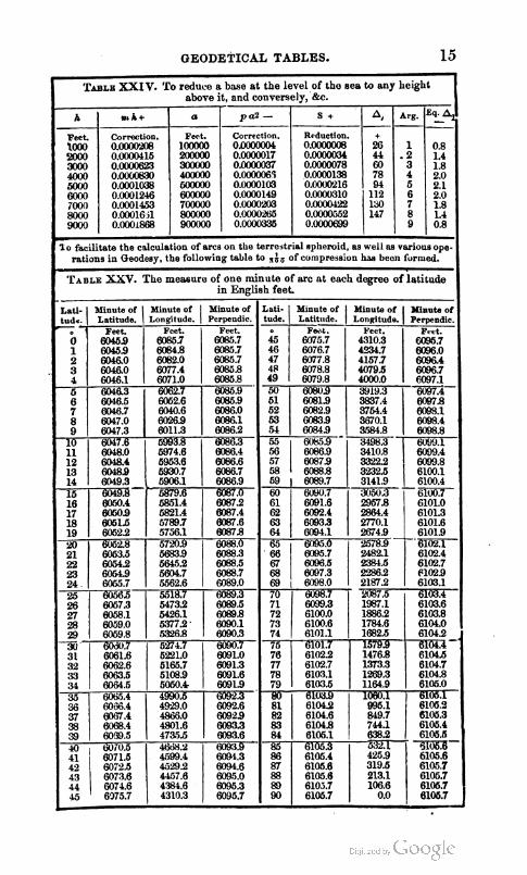
GEODETICAL TABLES. 15

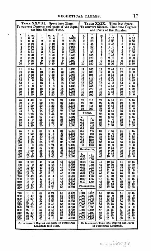
GEODETICAL TABLES. s
' ~ A ~ L E SXVIII. Space into Time. .
To convert Degrees and parts of the Equa- tor into Sidereal Time.
- 1 40 21 1 24 21 1.400 21 315 21 5 15 21 5 16 2 0 22 128 22 1.466 22 330 22 530 22 530 220 23 132 23 1.633 23 345 23 545 23 646
29 715 29 715 30 730 30 730 ---
75 5 0 31 2 4 2.065 80 620 32 2 8 90 6 0 33 212 100 6 40 34 2 16 110 720 35 220 Pa 8 0 36 224
" l5 l5 38 930 38 930
ZSO 1720 50 320 50 I230 - --
Or to convert Dugreen nnd pmts of Terrestrkl Or to convert Time into Degree8 and Par- Longitude into Time. of Terrestriul Lonfitudu.
TABLE n I X . Time into Space. To convert Sidereal Timn into Degrees
and Parts of the Equator. O
1 2 3 4 5 6 7 8 9 10 -
h. 1 2 3 4 5 6
10
11 12 13 14 15 16 17
h. m. 0 4 0 8 012 016 010 024 028 032 036 0 40
' 1 2 3 4 5 6 7 8 9 10
' 15 30 45 60 75 90
7 1 0 5 8 1 2 0 9 1 3 5
150
165 180 195 210 226 240 255
11 12 13 14 15 16 17
m. s. 0 4 0 8 012 016 020 024 028 032 036 0 40
" 1
3 4 5 6
10
I. 0.066
20.133 0230 0266 0.333 0.400
7 0 . 4 8 8 80.533 90.600
0.666
11 12 13 14 15 16 17
m. 1 2 3 4 5 6 7 8 9 10
11 12 13 14 15 16 17
0.733 0.799 0.866 0939 1.000 1.066 1.133
0 44 0 48 0 52 0 56 1 0 1 4 1 8
" ' 015 030 045 1 0 115 130 145 2 0 215 2 30
2 45 3 0 3 15 3 30 3 46 4 0 415
0 44 0 48 0 52 0 56 1 0 1 4 1 8
11 l2 13 14 16 16 17
8.
1 2 3 4 6 6 7 8 9 10
11 12 13 14 15 16 17
' " 015 030 065 1 0 115 130 145 2 0 215 2 30
2 45 3 0 3 li 3 30 3 45 4 0 415
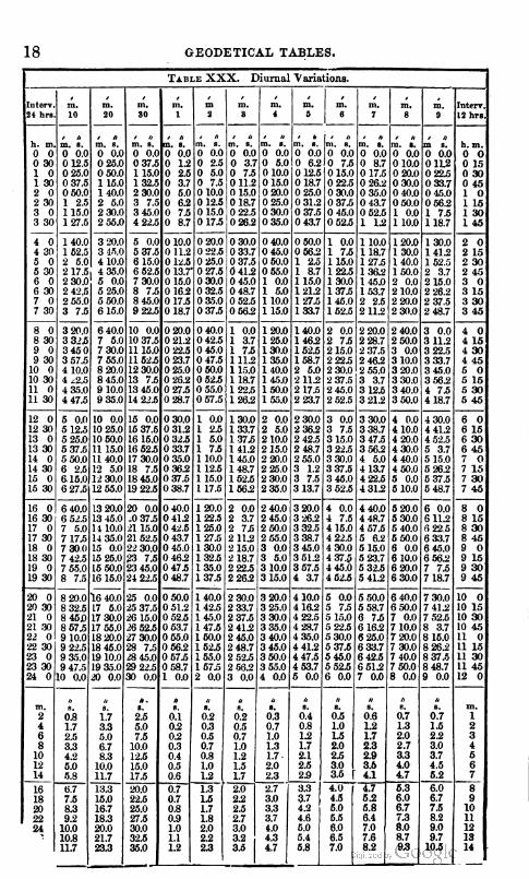
18 GEODETICAL TABLES. I
T A ~ L E XXX. Diurnal Variations.
24 hrs. 10 20 80 1 1 8 4 8 9 LZhrs.
0 0 0 30 1 0 1 30 2 0 2 30 3 0 3 30
, * h . m . m . 8 .
0 0.0 0 12.5 0 25.0 0 37.5 0 50.0 1 2.5 115.0 127.5
, n m.8. 0 0.0 0 25.0 0 50.0 1 15.0 140.0 2 5.0 2 30.0 2 55.0
4 0 140.0 3 20.0 5 0.0 0 10.0 0 20.0 1 52.5 3 45.0 5 37.5 0 11.2 0 22.5 2 5.0 4 10.0 6 15.0 0 12.6 0 25.0 2 17.5 4 35.0 6 62.5 0 13.7' 0 27.5 2 30.0' 5 0.0 7 30.0 0 16.0 0 30.0 2 @,5 5 25.0 8 7.5 0 16.2 0 32.6 2 55.0 5 60.0 8 45.0 0 17.6 0 35.0 3 7.5 6 15.0 9 22.5 0 18.7 0 37.6 ------- 3 20.0 6 40.0 10 0.0 0 20.0 0 40.0 3 316 7 5.0 10 37.5 0 21.2 0 42.5 3 4 5 0 730.01115.00B.5 045.0 3 57.5 7 55.0 11 62.5 0 23.7 0 17.5 4 10.0 8 20.0 12 30.0 0 25.0 0 60.0 4 ~2 .5 8 45.0 13 7.5 0 26.2 0 52.6 4 35.0 9 10.0 13 46.0 0 27.5 0 55.0 4 47.5 9 35.0 14 225 0 28.7 0 57.5 ----- 5 011 10 0.0 15 0.0 0 30.0 1 0.0 5 12.5 10 25.0 15 37.5 0 31.2 1 2.5 5 25.0 10 50.0 16 15.0 0 32.6 1 5.0 5 37.5 11 15.0 16 62.5 0 33.7 1 7.5 5 50.0 11 40.0 17 30.0 0 35.0 1 10.0 6 2.5 12 5.0 18 7.5 0 36.2 1 12.6 615.01230.01845.0037.6 116.0 6 27.5 12 55.0 19 22.6 0 38.7 1 17.5 - - 6 40.0 13 20.0 20 0.0 0 40.0 120.0
0 30.0 0 33.7 0 37.5 0 412 0 45.0 0 48.7 0 52.5 0 562
1 0.0 1 3.7 1 7.5 111.2 1 15.0 1 18.7 1 22.5 126.2
130.0 133.7 1 3 7 5 141.2 146.0 148.7 152.5 166.2 ------ 2 0.0 2 3.7 2 7 6 2 11.2 2 15.0 2 18.7 2 B5 2 26.2
2 30.0
r r r a m.8. 0 0 37.5 1 15.0 1 32.5 2 30.0 3 7.5 3 45.0 4 22.5
16 30 17 0 17 30 18 0 18 30 19 0 19 30
m 0
0 40.0 0 46.0 0 50.0 0 65.0 1 0.0 1 5.0 1 10.0 1 15.0
120.0 125.0 13n.O 135.0 140.0 1 45.0 1 60.0 155.0
2 0.0 2 5.0 2 10.0 2 15.0 2 20.0 2 25.0 230.0 2 35.0
2 40.0 2 45.0 2 50.0 2 55.0 3 0.0 3 5.0 3 10.0 3 15.0
3 20.0 10 15 10 30 10 45 11 o
13 45.0 11 10.0 14 35.0 15 0.0 15 25.0 15 50.0 16 15.0 ----- 16 40.0
6 52.5 7 5.0 7 17.5 7 30.0 7 42.5 7 55.0 8 7.5
8 m.0
m.8. 0 . 0 0 0 . 0 0
0 1.2 0 2.5 0 3.7 0 5.0 0 6.2 0 7.5 0 8.7
/I I, /, I d
(2 ;i ;:7 c 7 Y
20 30 21 0 21 .W 22 o
17 5.0 17 30.0 17 55.0 18 20.0
10 37.5 21 15.0 21 52.5 22 30.0 23 7.5 23 45.0 24 2 . 5
25 0.0 8 32.5 8 45D 8 67.5 9 10.0
----------- m. a.
0 . 0 0 0 2.5 0 5.0 0 7.5 0 10.0 0 12.5 0 15.0 0 17.6 -
0 60.0 0 56.2 1 2.5 1 8.7 1 15.0 121.2 1 27.5 133.7
140.0 146.2 162.5 168.7 2 5.0 2 11.2 2 17.5 2 23.7
2 30.0 4 36.2 2 42.5 2 48.7 2 55.0 3 1.2 3 7.5 3 13.7
3 20.0 3 26.2 3 32.5 3 38.7 3 45.0 3 51.2 3 57.5 4 3.7
4 10.0
1 0.0 1 7.5 115.0 122.5 1 30.0 137.5 1 46.0 152.5
2 0.0 2 7 6 215.0 2 22.5 2 30.0 2 37.5 2 45.0 2 52.5
3 0.0 3 7.5 3 15.0 3 22.5 3 30.0 3 37.6 346.0 3 52.5 - 4 0.0 1 7.5 4 15.0 4 22.5 4 30.0 4 37.8 145.0 4 52.6
5 0.0 25 37.5 26 15.0 26 52.5 n 30.0
0 412 0 42.6 0 43.7 0 45.0 0 46.2 0 47.6 0 48.7
0 50.0
m . 8 .
0 . 0 0 0 3.7 0 7 5 0 11.2 0 15.0 0 18.7 0 22.5 0 26.2
1 10.0 1 18.7 127.5 136.2 146.0 153.7 2 2.5 2 11.2
2 20.0 2 28.7 237.5 2 462 2 65.0 3 3.7 3 125 3 212 -------- 3 30.0 3 38.7 3 47.5 3 56.2 4 5.0 1 13.7 422.6 131.2
4 40.0 122.5 1 25.0 127.5 130.0 1 3 2 6 1 35.0 1 37.5
140.0
130.0 141.2 152.5 2 3.7 2 15.0 2 26.2 2 37.5 2 48.7
3 0.0 3 11.2 322.5 3 33.7 3 46.0 3 562 4 7 5 4 18.7
4 30.0 4 41.2 4 51.5 5 3.7 5 15.0 5 26.2 6375 5 48.7
6 0.0
120.0 1 30.0 140.0 160.0 2 0.0 2 10.0 2 20.0 2 30.0 ------ 2 40.0 2 50.0 3 0.0 3 10.0 3 20.0 3 30.0 3 40.0 3 50.0
4 0.0 4 10.0 4 20.0 4 30.0 4 40.0 4 60.0 6 0.0 5 10.0
6 20.0
0 51.2 0 52.5 0 53.7 o w .0
m.
0 6.0 0 10.0 0 15.0 0 20.0 0 25.0 0 30.0 0 35.0
2 0 2 15 2 30 2 4.5 3 0 3 15 3 30 3 45
4 0 4 1 5 4 3 0 4 45 5 0 5 16 5 30 5 45
6 0 6 15 6 30 6 45 7 0 7 15 7 3 0 7 45
8 0 4 48.7 4 57.6 5 6.2 5 15.0 5 23.7 5 33.5 5 41.2
142.6 145.0 147.5 160.0
5 30.0 5 40.0 6 50.0 6 0.0 6 10.0 6 20.0 6 30.0
I s # c , s r * , l , , n , l , . , , 8 . m .
0 . 0 0 0 . 0 0 0 6.2 0 12.5 0 18.7 0 25.0 0 31.2 0 37.6 0 43.7
2 33.7 2 37.5 2 41.2 2 45.0
0 . n ~ 8.
0 7.6 0 15.0 0 22.5 0 30.0 0 37.5 0 45.0 0 52.5 ------
10 0
6 112 6 22.5 6 33.7 6 45.0 6 56.2 7 7.5 7 18.7
6 50.0
m. 0 . 0 0 0 . 0 0
0 8.7 0 17.5 0 26.2 0 35.0 0 43.7 0 62.5 1 12
8 15 8 30 8 45 9 0 9 15 9 30 9 45 -
3 25.0 3 30.0 3 35.0 3 40.0
8.
0.0 0 112 0 22.5 0 33.7 0 45.0 0 56.2 1 7.5 118.7
1 . m . 1 . m 0 . 0 0
0 10.0 0 20.0 0 30.0 0 40.0 0 50.0 1 0.0 1 10.0
6 40.0
h.m. 0 0 0 15 0 30 0 45 1 0 1 15 1 30 1 45
4 16.2 4 22.5 4 B.7 4 35.0
7 30.0 5 7.5 5 15.0 5 22.5 5 30.0
6 58.7 6 7.5 6 16.2 6 25.0
6 50.0 7 0.0 7 10.0 7 m.0
7 41.2 7 52.5 8 3.7 8 15.0

RAILWAY TABLES. 19
I T*BLE XXXI. Shewing the lengths of horizontal lines equivnlent to the se~ernl rncending and descending planes, the length of the plane being unity ; In re- ference to the different classes of Engines, including the gross l od , with engine and tender.
First Class Engines, First Claas Engines, Second Clnss Engines. Secund Class Enginrs, Lond 100 tons. Load 60 tons. Load 80 tons. Load 40 tons.
Grduli- Equivalent Horizontal Equivalent Horizontal Equivalent Horizontal Equivalent Horizontal
Planes. Planes. Plnnes. ------
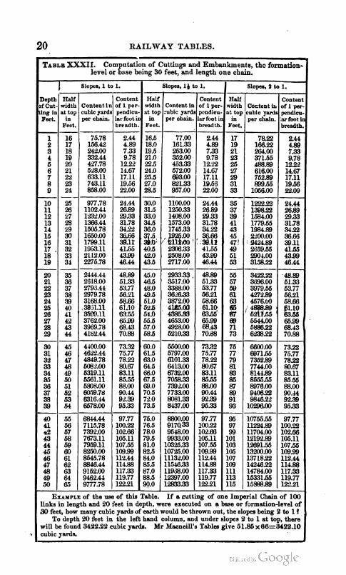
20 RAILWAY TABLES. v
TABLB
*
Depth of Cut- Ung in Feet.
1 2 3 4 6 6 7 8 9
10 11 12 13 14 15 16 1 7 . 18 19
20 21 22 23 24 25 26 n 28 29
30 31 32 33 34 85 36 37 38 39
40 41 &! 43 44 45 46 47 48 49 50
links 30 feet, how many cubic ysrds of earth would be thrown out, the slopes being 4 to 1 ?
To depth 20 feet in the left hand column, and under slopes 2 to 1 at top, there will be found 3422.22 cubic yards. Mr Macneill's Tables give 61.86x66=5122.10 cubic yards.
of Cutting8 and being 30 feet, and length
XXXII. Computation level or b ~ s e
Half width at top
in Feet.
16.5 18.0 19.5 21.0 22.5 24.0 25.5 27.0 28.5
30.0 31.5 33.0 34.5 36.0
3: 40.5 42.0 43.5
45.0 46.5 48.0 49.5 510 5Yb 54.0 55.5 57.0 58.6
'60.0 61.5 63.0 61.5 66.0 67.5 69.0 70.5 72.0 73.5
76.0 76.5 78.0 79.6 81.0 82.5 84.0 85.5 87.0 88.5 90.0 -
Table. depth,
Half width at top
In Feet.
16 17 18 19 20 21 22 23 24
26 26 27 28 29 30 31 32 33 34 ---- 35 36 37 38 .B M 41 42 43 44 --- 45 46 47 48 49 60 51 62 63 64
65 56 57 58 69 60 61 62 63
65
EXAMPLE in length
Embankments, thc formation- one chain.
Half width at top
in Feet.
17 19 21 23 26 !27 29 31 33
35 37 39 41 43 45
' 4 7 49 61 53
55 57 59 61 63 tJ6 55' 89 71 73
76 77 79 81 83 86 87 89 91 93
95 97 99
101 103 105 107 109 111 113 115
base or
Slopes, I) to
Content in mbic yards per chain.
77.00 161.33 253.00 352.00 453.33 572.00 693.00 821.33 957.00
1100.00 1250.33 1408.00 1573.00 1745.33
8 2306.33 2508.00 2717.00 ---- 2933.33 3517.00 3388.00 3626.33 3872.00 4W.aO 4386.6 .i6m.00 4928.00 5210.33 -- 5500.0 5797.00 6101.33 6413.00 6732.00 7058.33 7392.00 7733.00 8081.33 8437.00
8800.00 9170.33 9548.00 9933.00
1C325.33 10725.00 11132.00 11546.33 11933.00 1M97.00 12833.33
I f a cutting were executed
Slopes, 1 to
Content in cubic yards per chain.
75.78 156.42 242.00 332.44 427.78 528.00 633.11 743.11 858.00
977.78 1102.44 1'232.00 1366.44 1505.78 1650.00 1799.11 1953.11 2112.00 2275.78
2444.44 2618.00 279S.44 2979.78 3168.00 5831.11 1 3762.00 3969.78 4182.44
4400.00 4622.44 4849.78 M)82AXl 5319.11 6561.11 5808.00 60.59.78 6316.44 6578.00
6844.44 7115.78 7392.00 7673.11 7959.11 8250.00 8545.78 8846.44 9152.00 9462.44 9777.78
of the use and 20
1.
Content of I per- pcndicu- lar foot in brendth. --
2.44 4.89 7.33 9.78
12.22 14.61 17.11 19.56 22.00
24.44 26.89 29.33 31.78 34.22
2 : 41.55 43.99 46.44
-
48.89 51.33 53.77 66.21 68.66 61.10 63.55' 65.99 68.43
' 70.88
73.32 75.77 78.22 80.67 83.11 85.65 88.00 90.44 92.39 95.33
97.77 100.22 102.66 105.11 107.56 109.99 112.44 114.88 117.33 119.77 12291
of one on a
Slopel, a to
Coctent i cubic yards per chain.
78.22 166.22 2Cx1.00 371.55 488.89 616.00 752.89 899.56
1056.00
1222.22 1398.22 1584.00 1779.55 1984.89 2200.00 a42PB 2659.56 2904.00 3158.22 --- 3422.22 3696.00 3979.56 427289 4576.U) . 4888.89 . 62i1.55 ' w o o 688622 6238.22
6600.00 6871.55 7362.89 7744.00 8144.89 8 5 . 5 6 8976.00 9406.22 9846.22
10296.00
10755.55 11!224.89 11704.00 12192.89 12691.55 13200.00 13718.22 1424622 14784.00 16331.55 15588.89
Imperial Chain formation-level
1.
Content of 1 per- pend~cu- lar foot in breadth. --
2.44 4.89 7.33 9.78
1222 14.67 17.11 19.56 22.00 ---------- 24.44 26.89 29.33 31.78 34.22
% 4155 4399 46.44
48.89 51.33 53.77 56.21
.66 %.TO 63.55 66.99 68.43 70.88 ---- 73.32 75.77 78.22 80.67 83.11 85.55 88.00 90.44 92.39 95.33
97.77 100.22 102.66 105.11 107.55 109.99 113.44 114.88 117.33 119.77 lB.21
of this feet in
1.
Content of 1 per- pendicu- ,fir foot in breadth.
24.4 4.89 7.33 9.78 1232 14.67 17.11 19.56 22.013
24.44 22.89 9.33 31.78 34.22 36.66 39.11 41.55 43.99 46.44
48.89 51.33 63.77 66.21 68.66 )l.lO 63.65 6 5 s 68.43 70.88
73.22 75.77 78.22 80.67 83.11 8565 88.00 90.44 92.39 95.33
97.77 100.22 102.66 105.11 107.55 109.99 1l2.44 114.88 117.33 119.77 P22.21
of 100 of