Embed Size (px)
Citation preview

SOME ASPECTS.OF STRATIFIED FLOW
IN CLOSED CONDUITS
by
Pah-I Chen, B.s., M.s.
Thesis subnitted to the Graduate·Faculty of the
Virginia Polytechnic Institute
in candidacy for the degree of
APPROVED1
or. T. s. Chang
Prof. F. J. Maher
DOCTOR OF PHILOSOPHY'
in
Civil Engineering
or. J.M. Wiggert, Chairman
Dr. H. M. Morris
or. L. w. Rutland
August, 1966
Blaeksburg, Virginia
I.
II.
III.
IV.
v. VI.
VII.
VIII.
IX.
x. XI.
XII.
2
CONTENTS
LIST OF FIGURES• • • • • •
INTRODUCTION •••••••
EXPERIMENTAL APPARATUS. • •
• • • • • • • • • •
• • • • • • • • • •
• • • • • • • • • • LITERATURE REVIEW • • • •
DESCRIPTION OF ANALYSIS. • • • • • • • • • • • • • • • • • • • • • •
EXPERIMENTAL INVESTIGATIONS• • • • • • • • • • CONCLUSIONS AND RECOMMENDATIONS • • • • • • • • ACKNOWLEDGMENTS •
NOMENCLATURE • • • • • • • • • • • • • • • • • • • • • • • • • • • • • • • •
APPENDIX. • • • • • • • • • • • • •
BIBLIOORAPHY • • • • • • • • • • • •
VITA • • • • • • • • • • • • • • •
• •
• • • •
• • • •
• • • • • • • •
Page
3
4
5
ll
15
32
40
43
45
46
50
54

3
I. LIST OF FIGURES
Title Page
Fig. l Sketch of the Experimental Apparatus • • • • 7
Fig. 2 Sketch of the Cartesian Coordinates • • • • 16
Fig. 3 Sketch of Two-layered Flow. • • • • • • • • 17
Fig. 4 A Square Net. • • • • • • • • • • • • • • • 18
Fig. 5 Square Net at the Interface • • • • • • • • 20
Fig. 6 Sketch of the Grid for Three Inches Diameter Pipe. • • • • • • • • • • • • • • • 22
Fig. 7(a) Computed Result of the Velocity Distribu-tion at y :11 3/5 inch and oP/a x a -0 .001165. • 23
Fig. 7(b) Vertical Velocity Profile for Interface Y = 3/5 in • • • • • • • • • • • • • • • • • 24
Fig. 7(c) Horizontal Velocity Profiles for Interface Y = 3/5 in •••• • • • • • • • • 24
Fig. S(a) Vertical Velocity Profile for Interface Y = 0 in. • • • • • • • • • • • • • • • • • 25
Fig. S(b) Horizontal Velocity Profile for Interface Y = 0 in. • • • • • • • • • • • • • • • • • 25
Fig. 9 Sketch of An Internal surge Wave in a Pipe • 26
Fig. 10 Notation for An Internal surge Wava • • • • 27
Fig. 11 Photograph of an Internal surge wave in a Pipe • • • • • • • • • • • • • • • • • 33
Fig. 12 Comp~=ison of the Theoretical and the Experiwental Internal surge wave Velocity in a Pipe • • • • • • • • • • • • • • • • • 35
Fig. 13 Photograph of an Internal Hydraulic Jump in a Pipe • • • • • • • • • • • • • • • • • 37
Fig. 14 Relation of the Conjugate Depth Ratio to the Discharge Ratio • • • • • • • • • • • • 39

4
II. INTRODUCTION
Stratified flow of two fluids is defined as simultaneous
flow of two fluids with different physical properties such
that one is flowing over the other and there is a noticeable
interface in between. It was first studied more than a cen-
tury ago, however it has attracted increased attention only
in the last three decades. The literature available deals
with studies in open channel fields rather than experiments
performed in closed conduits.
The aim of this study is to conduct four investigations
of stratified flow in circular closed conduits. The studies
are of velocity distribution, internal surge wave, mutual
intrusion, and internal hydraulic jump.
The equation of motion will be first derived for the
velocity distribution and then solved by the method of finite
differences. No experiments were done due to technical
difficulties.
The equation of the velocity of the surge wave will be
derived, in which a concept of energy loss at the surge wave
front is introduced. Experimental data given show good
agreement with the analytical result in this part.
Because of complex pipe geometry and the non-
antisymmetric intruding property which was observed in ex-
periments, only experimental evidence will be described in
mutual intrusion.

5
A relation of the ratio of conjugate depth to the ratio
of discharge of the two phases will be drawn for the internal
hydraulic jump from experimental results.

6
III. EXPERIMENTAL APPARATUS
Before the actual apparatus was built in the Fluid
Mechanics Laboratory of the Virginia Polytechnic Institute,
a qualitative observation of stratified flow was performed in
the laboratory of the Chemistry Department of the same Insti-
tute. A small scale setup was built which consisted partly
of two funnels to contain water and carbon tetrachloride.
Each funnel was connected to a 4 ft. long, l~ in. diameter
glass tube by plastic tubing. It was found that the flow at
the entrance section experienced turbulent mixing, farther
in the pipe formed a laminar flow with a clear interface,
with the layer of water moving over the layer of carbon
tetrachloride. The lower layer was tending to decrease its
depth as it reached the outlet to a free fall. An internal
hydraulic jump was created by attaching a dam shape obstacle
to the bottom wall of the glass tube. The gravity current
was observed when carbon tetrachloride entered into the tube
which was first filled with water. A quantitative investi-
gation was therefore begun by building the following
apparatus.
The apparatus used in this investigation consisted of
a transparent pipe, a liquid pump, pressure measuring de-
vice, volumetric tank, receiving tank, a separator and two
head tanks. The experimental setup arrangement is shown in
·Figure l.

Separator Tank
~ steel pipe as supply line
11:i" steel pipe for surplus flow ~~
3" plexiglas pipe as tes_t~~~~ section
Pump~,
Receiving tank
Quick closing __ gate valve
Figure 1. Sketch of the Experimental Apparatus
...J

8
The transparent pipe was made of plexiglas. The pipe
was twelve feet long and three inches in diameter. It was
constructed of three pieces of plexiglas tube with victaulic
snap joint couplings. The wall of the pipe was smooth.
Fuel oil and water were fed into the plexiglas pipe
through the entrance section which consisted of a three inch
Y elbow, 3 x l~ inch reducers, l~ inch size globe valves and
l~ inch steel pipes.
The fluids were circulated by pumping them from the re-
ceiving tank to the separator and drawing them separately to
two constant head tanks. A one-inch size gate valve was
used to control the pumping rate near the pump inlet. A
three inch Lunkenheimer quick operating valve was installed \
in the middle of the plexig!as pipe during the studies of
mutual ·intrusion and surge waves.
The pressure taps were made by drilling four 1/16 inch
holes on the half circumference of the plexiglas pipe wall.
Brass couplings were drilled, tapped and cemented over these
holes. Attached to the couplings were clear plastic mano-
meter lines which were connected to glass tubing mounted on
a board.
The outlet of the plexiglas pipe was restricted by end
plates with different size openings of l/4, 3/4, l, 1-1/4,
1-1/2, l-3/4 and 2 inch in diameter. The end plates were
made of 3/8 inch thick aluminum plate. Their function was

9
to provide a full flow in the pipe and also to control the
discharge.
The rate of flow at the upstream end of the pipe was
controlled by a globe valve for each head tank. Constant
head and steady flow was attained by observation of an el-
bow meter ahead of each globe valve. The flow discharge
was measured by catching the effluent liquids and weighing
them over a time interval.
To separate the effluent liquids, a separator was built
using the properties of density difference and immiscibility
of water and fuel oil when they travel a considerable dis-
tance. Each liquid was induced into different compartments
where it was drawn to different head tanks through one inch
pipes. The constant head tank consisted of an overflow
section for surplus fluid. The surplus fluid returned to
the receiving tank through al~ inch pipe.
The separator and the constant head tanks were made of
plywood. The spaces in the plywood joints were filled with
caulking compound to prevent leakage. The plywood surface
was first varnished and later coated with a special chemical
resistant paint to protect it from fuel oil wash out.
The fluids used were water and No. 2 fuel oil. These
fluids are generally considered immiscible, but impurities
cause some mixing. Hence, instead of determining the speci-
fic gravity and the kinematic viscosity before using them,

10
an alternate was to measure these properties during each
. experimental group.
A glass cylindrical pyconometer was used to determine
the specific gravity of each fluid. A Saybolt viscometer
with universal and furol orifices was used to determine
their kinematic viscosity. The specification and method of
tests are listed in the 1964 ASTM standards (1). The following fluid properties were founds
Fluid
Water
No. 2 fuel oil
at 77°F
Specific Gravity -
0.999
0.835
Absolute Viscosity CZ< = fl )
0.000024
0.0000351

11
IV. LITERATURE REVIEW
Most literature available in the field of stratified
flow in closed conduits are basically experimental contribu-
tions. However, a review of the literature in the open chan-
nel aspects will provide essentially the same knowledge on
this investigation.
In 1847, Stokes (22) studied wave motion along the com-
mon surface of two liquids when one rests on the other.
Wave motion under the influence of gravity in stratified
flow was also studied by Greenhill (5) in 1887 and Love in
1891.
Three M.I.T. students, Reichardt (19), Kelakos (S) and
Crowley (8) investigated two phase flow in circular pipes in
the mid 1930 1s. They used transparent pipes to observe the
flow patterns, however their effort was primarily on deter-
mining pressure drop in two-phase flow of unstratified fluids.
Pressure drop studies were also carried out in 1939 by Boelter
and Kepner (2). They studied two-phase flow occurring in a
fuel distributing system for heaters. In 1947 a report of
the University of Delaware presented Gazley and Bergelin's
(4) experiments which covered flow of low air and water dis-
charge rates in a one inch pyrex tube. They studied the ef-
fect of the existing hydraulic gradient in stratified flow.
A thesis presented at the University of Oklahoma in 1953 by
Schneider (20) tried to experimentally distinguish six

12
different regions of two-phase flow in a pipe. He failed to
draw a demarcation line between semi-annular and annular
flow to cresting (or mist-annular) flow. His presentation
was also limited to the pressure drop.
Theoretical attempts attracted the attention of geo-
physicists, meteorologists and hydraulicians, starting about
three decades ago. Their interest was not flow in closed
conduits, but instead they dealt with density currents in
oceans and rivers, waves in the lee of mountains, flow
characteristics at the interface, gravitational waves in a
stratified flow, etc. Studies related to the topics of this
investigation are described in the following paragraphs.
Keulegan (1944) (9) studied the velocity distribution
in the laminar boundary layers at the interface of two
liquids in rectilinear motion. This was based partially on
Prandtl 1s theory to determine the thickness of the layer and
the stress at the interface. Each liquid layer was assumed
to extend to infinity. He also studied (25) mutual intrusion
of two fluids separated by a gate in a flume.
A series of papers presented by Long (13)(14)(15) at
Tellus contained theoretical and experimental treatments of
the steady state pattern of a stratified flow over a barrier.
The channel he used for experiments was 20 feet long, 6 inches
wide and 2~ feet high. His photographs show very nice lee
wave forms due to barriers of different heights and different
Froude numbers.

13
Ippen and Harleman (1952) (6) studied the velocity dis-
tribution of stratified flow in a rectangular flume by tak-
ing motion pictures of falling droplets. They obtained the
equation of motion by considering the laminar flow of two
layers of incompressible fluids to be analogous to the case
of laminar flow between parallel plates with the upper plate
in motion.
Mutual intrusion was studied by Yih (1947) (24). Hi~
experimental data show quite good agreement with the equa-
tion he derived based upon energy considerations. Yih and
Guba (1954) (25) studied the internal hydraulic jump of a
stratified flow by the momentum approach. Their experiments
included three different cases which were1 (1) the upper
layer at rest, (2) the lower layer at rest, (3) both layers
in motion. In the third case, they obtained a surge by fill-
ing a flume sealed at the downstream end with lighter fluid
and then.discharging the heavier fluid into it at the bot-
tom. When the heavier fluid reached the end of the channel,
it fonned a surge which propagated upstream. Because they
considered the surge as a moving hydraulic jump, the surge
velocity was not of interest in their study. Yih (26) pub-
lished a remarkable book in 1965 entitled Dynamics Q! !i2n,-
homogeneous Fluids. With its well prepared bibliography,
the book was considered very helpful during the collection
of literature reviews of this investigation.

14
In 1959, Lofquist (12) was able to measure the velocity
distribution of salt water flow under the fresh water which
.was initially at rest. The methods he adopted were photo-
graphing a dye trace and observing the time required for a
pellet floating in the interface to trace one meter down-
stream. The first method was for the vertical plane and the
second one applied only at the interface of the stratified
flow.

15
V. DESCRIPTION OF ANALYSIS
A. General Considerations
The stratified flow under consideration is two-layer
flow in a horizontal, circular pipe. It is assumed that two
incompressible fluids, miscible only to certain extent, are
flowing at different depths simultaneously under a constant
pressure gradient~p/ox. Frictional forces are neglected.
Transient phenomenon due to sudden gate openings exist for a
very short period for short pipes, so its effect will not be
considered.
B. Velocity Distribution
In order to find the equations of motion in a laminar
multi-layered flow system, it is reasonable to study the
equations of motion in a simple laminar fluid system, then
extend the equations to each layer, proceeding by assigning
appropriate boundary conditions for each layer and the whole
system.
The Navier-stokes equations are
au.. ;Ju, , oP + ~ o'"U,· + f. oi + "'-j ~ X j = - f iJ)'-;, f ~1-i lJt'.j '
where i is the range index and j is the summation index over
l, 2 and 3.
For a steady flow, the first terms vanish. The system
is under a constant pressure gradient, no external force is
acting. Then the Navier-stokes equations become
16
· ;,u, 1 d P ~ ;>iu,: uj -;cj = -7 ~;t., + 7 JX.j ~-"j·
(l)
.For convenience of the following analysis consider.the Car-
tesian coordinates (x, y, z) as shown in Figure 2.
Figure 2. Sketch of the Cartesian Coordinates
Let u1 = u, u2 = v, and u3 = w. Since v = w m O in y and z
directions, equations (l) may be written as
JU. I ~ P ,-',' ( ;tu ;) a.Lt ().. 4)' == - f JX + f ~)'a.+ lJ 1" + ~'aL()
4 .c, (la)
0 = - J_ aP -+ o f JJ (lb)
o=--1 cP+o f Ji..
(le)
By equations (lb) and (le) we get p = p(x) which states the
pressure changes along the x axis only.
The continuity equation is ~ "'. J_o ~ Xj
which reduces t;o oU Tx - 0
i.e. u = u(y,z)

17
Therefore, equation (la) simplifies to
I '<J p ---- """ i) )(.
(2)
Equation (2) for two-layered systems may be written as 'J ,.u,· 31.u, I "pf'
+ - -J 1z. - J )l J ~.I /'i
(3)
where 1 = l at d1,
• i Ill 2 at d2,
as indicated in Figure 3.
d
_.,___._ _ --d, d,
Figure 3. Sketch of Two-layered Flow
Let U·(" <) - -' aP [ U·(l l)+t;t+zi.;)
" ,, -4,;"i 1X ' 1
From the transformation, we can rewrite equation (3) as
+ (4)
Equation (4) is a Laplace equation in a plane. It can be
solved by finite difference methods.

18
"' Figure 4. A Square Net
A square net is shown in Figure 4. If the side of each
square is a, the partial differentiation of a function U
with respect toy at point O can be written as
;)U [U U,-Uo ar~77= a.
U, -Uo Uo -U4 ~~ a a. ~ :::, ~~~~~~~~ J 11.
U, ... 2.U0 + U4 (5)
Similarly we get o .. U Ua.-2.Uo-+-U3 ~i ... ~ a.z. (G)
Substitution of equations (5) and (6) into equation (4) gives
For the case at point o•, the finite difference form of
equation. (4) is
U , + Uz., + U:,, + LJ4' - ( .t. ~ .L t ,.' ) U o' = 0 I >,. z. ~-4 Al. ""4
However, the7'.1s are considered to be 1 for the approximate
solution in this thesis.
As much experimental evidence supports the correctness
of a no-slip condition at solid-liquid, liquid-liquid inter-
faces, it is reasonable to conclude that the velocity on the

19
pipe wall is zero, and the velocity of each liquid at the
interface is equal. To express this clearly, write
In terms of ui, the above two expressions are
where and
(8)
a:/. 'J, == £- d.z ( 9)
n =~ -I _,,,AAz.
It is obvious that the shear stress on the interface
must be equal, which states gU1 dLll
/1 "if ==~1.~ hence
(10)
To express equation (9) and (10) in finite difference
form, examine Figure 5,

20
U .. u
LJ ~i U.zo U,.,t _,_ ~,- -,-
Figures. Square Net at the Interface
where dash lines indicate the interfaces y1 • Equation (9)
becomes
Equation
which are
012 = m022 + n(y 12 + z 2 )
013 = mU23 + n(yl2 + z2).
(10) may be expressed as Uz.1 -U~o _ U,1 - U,o
a. a.
U.z0 -u~.,. _ U,o - tJ,4 0.. a.
combined to
(9a)
(9b)
(9c)
(lOa)

21
Because no such U24 exists in d1 , and no such U11 exists
in d2, their appearance in the equation of motion must be
avoided.
According to Figure 5, write out equations (7) as
follows,
(7a)
(7b)
Adding equations (7a) and (7b) and substituting equation
(lOa) results in the following equation
(11)
Substituting equations (9a), (9b) and (9c) into equation
(11) results in the equation of motion,
at the interface, which satisfies the boundary conditions of
equal velocity and equal shearing stress.
Applying equations (7) to each layer, and equation (12)
to the interface, a solution will be obtained at each point
on the square net by the method of finite differences. The
final result is obtained by substituting 01 into the follow-
ing equations

22
Apparently, the smaller the grid size, the greater is
the accuracy of computed result. However, as a demonstration
it is considered to be accurate enough to have the grid size
3/10 x 3/10 square inches as shown in Figure 6.
- l-2-3-. I I -1-s-,-~-I I I I I
-a-9-10-11-1.1. ¢ J I I I J I - '.J-t/J-1$'-16- 7_ I I I I I
-/3-19-:u-:1.I-U-I I I I I
- ,z.3-L~°J.S'-.1,-:1.7-1 I I I I 1
-:z.3-;.?-.J0-31-~ (> I I I I I
-~1-JS'-36-1 I I I
-.37-3.t-:, 9 I I -fl
Figure 6. Sketch of the Grid for Three Inch Diameter Pipe
The U value near the pipe wall is set to be
¢ = -£2. =- ( f )z =-.2..2.S-
by equation (B). Because the flow is symmetric about y-
axis, only half of the flowing area needs to be studied.
There are 39 equations corresponding to 39 unknowns.
These 39 simultaneous equations are solved on the IBI.~
7040 computer. 'I'wo different interface heights, y = o and
ya 3/5 inches, are studied. Typical results of y = 3/5

23
inch and )p/)x = -0.001165 are shown in Figure 7(a).
VELOCITY DISTRIBUTION FOR STRATIFIED FLOW WITH INTERFACE AT Y=3/S IN
0.0201 0.0184 0.012s
0.0438 0.0409 0.0318 0.0173
0.0134 0.0694 0.0565 o.0374 0.0158
0.0162 0.0719 0.0594 0.0408 0.0197
o.os36 o.oso6 0.0422 0.0296 0.0149
0.0369 0.0349 0.0290 0.0204 0.0102
0.0243 0.0228 0.0188 0.0121 0.0057
0.0145 0.0135 0.0106 0.0058
0.0067 0.0061 0.0042
Figure 7(a). Computed Result of the Velocity Distribution at Y = 3/5 inch and ~p/ox = -0.001165.
Figure 7(b) shows the vertical velocity profile, and
Figure 7(c) shows the horizontal velocity profiles by the
result on Figure 7(a). Various sections shown on the verti-
cal axis are indicated by the grid points on Figure 6.
Points with a prime indicated the other half of the section.
The same kind of velocity profiles are plotted on
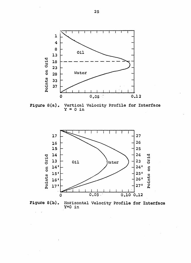
Figure 8(a) and Figure 8(b) for half oil and half water
flow. The computed result can be found in the Appendix.
C. Internal Surge~
The surge wave problem has been extensively studied for

l 4
ia 8 ..-i ~13 5 18
24
. m 23 .µ
Figure 7(b).
Figure 7(c).
,!:i 28 f 33
37
0 o.os velocity ft/sec.
0.10
Vertical Velocity Profile for Interface Y = 3/5 in
32 ' 12 ' ' ' 31 \ 11 ' \ 10 30 ' \ ,a ,a 29 \ 9 ..-i
..-i I s.c ~ 28 I 8 Ol
I
a 29' I 91 a 0 I 0
m 30 1 I 10 1 Cll I .µ .µ I 11 1 s::: s::: 31 1 I ..-i ..-i I 0 0 32 1 I 12 1 ii. ii. I
0 o.os 0.10 velocity ft/sec.
Horizontal Velocity Profiles for Interface Y = 3/5 in
25
l 4
8 13 Oil
'CS '" 18 H C) 23 s:: 0 28 Water Dl 33 .µ s:: '" 37 0 tlt
0 0 .05 · ·~ 0.12
Figure S(a). vertical Velocity Profile for Interface Y = 0 in
17 27
16 26 15 25
'CS 14 24 'CS '" '" M 13 23 M C) C)
s:: 14 1 24 1 s:: 0 0
(,I) 15 1 25 1 (,I) .µ 26 1
.µ s:: 16 1 C
.,; .,; 0 17 1 27 1 0 Pt Pt
0 o.os .. 0.10 0.12
Figure 8(b). Horizontal Velocity Profile for Interface Y=O in

26
one-phase flow in open channels. (As a matter of fact, it
can be considered as stratified flow with air flowing on the
upper layer). However, the surge wave in two-phase open
channel flow has only been treated as a moving hydraulic jump
by Yih (1947) (25).
When a gravity current reaches the gate at the end of
a pipe which was originally sealed with lighter liquid, an
internal surge wave is created. In general, this phenomena
is believed to be the result of an abrupt change in velocity
of the intruding current which produces a corresponding
change of momentum. Without further discussing the cause,
the progression of the surge wave for two-phase flow in a
pipe is to be investigated.
Following a conventional approach, the unsteady motion
of a surge can be treated as steady within a certain reach
by considering moving coordinates with the origin at the
surge front.
, V I f- 11'=0
1-------- q_ ___ - - gate at pipe end 1/:o f - V
(a) Unsteady Motion of An Internal Surge Wave
f l - a-v' /)
/-------t _ gate at pipe end jl--1,-----lu - a+v - a. I
(b) Steady Motion of An Internal Surge Wave
Figure 9. Sketch of An Internal surge Wave in a Pipe

27
As an internal surge wave progresses upstream, a con-
siderable amount of energy loss is suffered at the wave
front. Prestnnably, this energy loss is the major cause of
the reduction of surge height as the surge moves upstream.
The other factors of energy loss are the losses due to in-
terfacial shear and frictional force on the pipe wall.
A new concept is introduced for the energy loss at the
wave front by considering it to be the loss due to contrac-
tion and expansion of both layers. It is believed that
this energy loss concept will permit the consideration of
the internal surge wave as an internal hydraulic jump, be-
cause the idea of the hydraulic jump is always accompanied
by thinking of the loss. • energy (j) @
I a 1 a-v' - I ,
~'I -f ,._ I I
I I IJ I
(J. +'I - I f 1, 1 - a I
~ gate at pipe end
Figure 10. Notation for the Internal Surge Wave
The Bernoulli's equation for upper layer at points l
and 2 on either side of wave front is,
(13)
* Yih,C. s. (26), p. 133. 11Since hydraulic jumps are characterized by a loss of energy, it is questionable whether the change from one state to the other without energy loss can be called a hydraulic jump. 11

28
where h = internal surge wave height
he = head loss due to expansion
he = head loss due to contraction
hs m head loss due to inter facial shear
hf = head loss due to wall friction , ,~ f -0 .
-~av -f L -t -' = -'-;2 + h..,. h.e + kc -t-h.s + hf 2... j :ij 'I' i'
The continuity equation for the upper layer is
( (). - v') A 'I,' = o. A 1: a r Av,' - At/) -
At,' -I
V = and for the lower layer is
( a -t v) A,, a A'Ji.
V a ( A~.1. -ltt,J
A,,
(13a)
Let us neglect he, hs and hf in equation (13a) as they are
small compared with h8 • Noticing also that
he -= r.'J r a+ v- a..J z. - K. x_i - K a."l.K~' 2 1 - J.z_,- J 2.1
where k3 is a coefficient due to expansion loss which is a
function of expansion angle. Substituting v• and he into
equation (13a) we get, _i.a 2(.+ ~1..r,2.t P,= fL+h +K.
:z..3 2.9 "'J' 1' J For final state, the system is at rest, thus
1~ _ 1:,l. h 7--:;-+
Combining equa~ion (13b) and (14), we get
;zg ( 1;,1') h 0.. = -
~ K, + K_; K.1. i._ ,(, ~
.2. g ( ;f) Ii
.2Kt + K.3 ('/- .r,2
(13b)
(14)
(15)

29
Equation (15) states internal surge wave velocity is a func-
tion of the density of the liquids, wave height, ratio of
flowing area of both liquids and angle of expansion. It
holds for various flowing areas as long as the surge wave
is of small amplitude.
D. Mutual Intrusion
Two incompressible fluids of different specific gravity
are to be separated by a gate in a pipe. When the gate
opens, the mutual intrusion occurs. It is quite different
if these two fluids are gases. In that case, when the parti-
tion is suddenly removed, the high-pressure gas expands and
compresses the gas in the low pressure region. Instead, for
incompressible immiscible fluids, the fluid with lighter
density intrudes with the space occupied by the heavier
fluid and vice versa.
When Yih (1947) (24) investigated the intrusion prob-
lem in open flumes, he was already aware of the fact that
the interface is sloping instead of horizontal during the
intruding stage. Starting by assuming an equation for the
interface profile (although he knew it does not agree at the
sharp wave front) he sought an expression for the change of
the centroid of the intruding fluid mass at any time. Pro-
ceeding by the law of energy conservation which states the
potential energy loss by the heavier liquid is equal to the
potential energy gained by the lighter fluid plus the

30
kinetic energy gained by both fluids, an equation was de-
rived for the intruding velocity.
A complex geometry is already involved in a circular
pipe, and the non-antisymmetric intruding profile of the in-
terface makes the problem even more difficult. No analytical
result was satisfactorily attempted. Only experimental evi-
dence will be shown in the later parts of investigation.
However, it was felt that Yih 1 s approach does render some
insight for attack on the intrusion phenom~non,-especially
since his experimental data show fairly good agreement with
his theoretical results.
E. Internal Hydraulic Jumo
An internal hydraulic jump may be developed when the flow
passes over a dam-shape barrier which was attached on the bot-
tom wall of the pipe. Turbulent mixing of two fluids which
is one source of energy losses, is produced on or near the
sloping face of the barrier. This form of energy loss char-
acterized a special property of an internal hydraulic jump.
The energy losses can be found by the law of energy conserva-
tion on the jump and downstream sections. It is merely equal
to the change of potential energy and kinematic energy of
both layers between both sections. This loss includes loss
due to mixing, shear at the interface and the pipe wall.
Yih (25) has developed two momentum equations for both
layers of an open channel internal hydraulic jump, in which

31
he considered the pressure distribution at the interface 1$
hydrostatic, and the mean head over the jump section is the
average depth of the lighter fluid upstream and downstream
of the jump. The shearing forces at the interface and chan-
nel bottom are neglected in his equations. Similar equations
for a pipe flow can be obtained by adding pressure change ~: ·.
terms and modifying due to the pipe geometry which need not
be presented here.
Due to lack of an accurate velocity measuring device
for very slow fluid motion, the effort is only to develop
the relation of the conjugate depth ratio to the discharge
ratio of two fluids by experiment.

32
VI• EXPERIMENTAL INVESTIGATIONS
Experimental procedures, findings, and results are pre-
·sented in this part.
A. Internal Surge~
Three different experimental arrangements were made to
study the surge wave velocity.
l. A quiek closing valve was installed between the
first and second plexiglas test sections. The
downstream end was sealed. Fuel oil was fed
into the downstream section by small pump. Water
was provided by the head tank to the upstream
section.
2. Similar to the first arrangement except that the
valve was connected between the second and the
third test section.
3. Only two of the test sections were used. The
quick closing valve was fixed between these two
sections with other ends closed. Water and fuel
oil were pumped into these two sections separately.
Experiments started with recording the heads on both
sections. Two persons each with stop watches prepared for
the instantaneous gate removal. At the moment the gate
opened, the person at water section recorded the time for
fuel oil front to travel about four feet and marked the

33
height of interface about three feet away from the gate.
The other person watched for the surge wave to occur. When
the surge wave reflected at the dead end, the time, height
and the distance until it tended to flatten out with oncom-
ing water were recorded. Figure ll shows the surge wave as
it moves upstream.
Figure 11. Photograph of an Internal surge wave in a Pipe
The head at both sections were varied before the next
run was started.
It is found that the surge wave is of limited height.
The wave height was maintained at a constant value about

34
three to five feet away from the reflecting point. Then, it
became wavy and finally damped out. The experimental results
showed the change of head at both sections had no effect on
the surge wave velocity. But the first arrangement had a
slower surge velocity than the other, and the third arrange-
ment had the fastest surge velocity. That was 'because transi-
en~had no effect in short pipes.
The coefficient k 3 is adopted from streeter•s Fluid
Mechanics (23). k3 is considered to be 1.0 for expansion
angle around aoo.
All experimental results were quite agreeable with that
found by the approximate solution.
B. Mutual Intrusion
The same experimental arrangement was made as in the
third arrangement in the previous study.
Both persons recorded the intrusion heights and veloci-
ties of wave front at the same time after instantaneous gate
openings. Investigation ended when the intrusion front
reached the sealed end.
It was found that the interface, when both wave fronts
were about eight feet apart, was sloping instead of horizontal.
This is believed to be due to the short pipe. A horizontal
interface will presumably exist after the wave fronts travel
quite a distance.
Another observation was that the intruding wave profile
was not anti-symmetric on the two sides of the quick closing

_35
Sample of experimental dat~:
Symbol
•
0
* 0.8
0.7
o •. 6
'110.~ ...-1 al .. +> § 0.4 El .
•r-i .. 1-t a, 0.3 A . ~ ..
0.2
0.1
Arrangement y 1 (in)
1 22/32
2 23/32
3 28/32
h a (in) (fps)
26/32 0.429
20/32 0.497
22/32 0.560
0 0.1 0.2 0.3 0.4 0.5 0.6 0.7 0.8 Theoretical a
Figure 12. Comparison of the Theoretical and the Experimental Internal surge Wave Velocity in a Pipe

36
valve. Fuel oil always travelled faster than water. That
is, the fuel oil layer intruding over the water was thinner
than the water layer intruding at the bottom of the oil.
That phenomena may be caused by the inertia effect of speci-
fic gravity with the consequence that it forces a greater
amount of heavier liquid to intrude under the lighter one at
the moment the gate opens. The velocity of the fuel oil
front was about 0.63 feet per second, about 0.03 feet per
second faster than the water front as the following typical
data indicated.
Run Intruding Velocity (fr/sec) For Water Front For Oi Front
17 0.600 o.633
18 0.603 0.630
19 0.600 o.634
20 0.605 o.630
No apparent pressure influence was found which meant
transient effect was negligible at least for short pipes.
No satisfactory intruding profile is presentable.
c. Internal Hydraulic Jump
The following picture shows the internal hydraulic jump
occurring when a stratified flow passes dam-shape barrier in
a circular pipe.

37 ·
Figure 13. Photograph of an Internal Hydraulic Jump in a Pipe
Two different heights of dam-shape barriers were used
in this investigation. The barrier was attached and screwed .
to the bottom wall from tha exterior of the pipe.
Flow was regulated by the globe valves from each head
tank. The downstream gate was of a half-inch diameter open-
ing to obtain a stable stratified flow. Static pressure
manometers were mounted close to the barrier and a little
distance downstream. Two manometers were used, one at the
top, the other at the bottom of the pipe, both upstream and
downstream.
Every run began by measuring the pressure readings on
four manometers. The interface height was also measured up-
str .eam of the barrier, at the jump, and downstream of the

38
barrier. The flow was collected at the pipe exit by a mea-
suring tank and the collecting time interval recorded from a
stop watch.
A total of twenty runs were performed for l inch and
l~ inches height b:lrriers. Each run started with different
head at the head tanks and all measurements were recorded
until a stable flow prevailed in the entire pipe.
It was found that downstream interface positions were
about the same as that at upstream. The jump occurred on
or near the sloping face of the b:lrrier. Although there
was turbulent mixing at the jump, the interface still showed
clearly. The length of jump extended as far as two and one-
half inches.
On the pressure manometers, a change of pressure head
was indicated. It resulted from the contraction and expan-
sion of the flowing area due to the blocking of the dam-
shape b:lrrier.
The experimental results of the ratio of conjugate
depth to the ratio of each fluid discharge are shown in
Figure 14. The curve shows the expected result that the
greater the difference of the conjugate depths, the closer
is the discharge ratio of oil and water.

2i0
l,~
D2/Dil ._8
1.7
1.6
1.5 ~
1.4
1.3
1.2
1.1
1.0 0
a
10
•
& :::, .. ~
x for lf" barrier height 0 for l" barrier height
.IC
~o 30 40 50 60 ·70 so go 100 Q1/Q2
Figure 14. Relation of the Conjugate Depth Ratio to the.Discharge Ratio
\.,I \0

40
VII• CONCLUSIONS AND RECOMMENDATIONS
Four investigations of stratified fluid flow in closed
conduits were studied in this work, which includeds
1. numerical solution of velocity distribution by
using a digital computer,
2. analytical solution and experimental verifica-
tion of the internal surge wave velocity,
3. experimental observation of mutual intrusion
phenomena, and
4. experimental investigation of an internal hy-
draulic jump over dam-shape barriers.
As the computer solutions indicate, the velocity in the
lower layer is greater than that in the upper layer. Al-
though, the measurement of velocity for stratified flow in
a pipe is technically difficult (the author has tried with-
out success), a qualitative measurement will still enforce
the correctness of the analytical result. That is to adjust
the interface height to be at zero (half water, half oil
flow) and then collect the discharge at pipe outlet. It
was found the amount of water flowing out was more than oil.
In this experiment, the difference of the viscosity of water
and oil is not too great. If a fluid of a greater viscosity
was used for the bottom layer, a different result is antici-
pated. This nu.~erical solution can apply to conduits of
various flowing area.

41
Experimental results have shown good ag~eement with the
approximate solution for internal surge wave velocity. Ex-
cept for the restriction of small wave height, this solution
holds for surge waves of any flowing area. The flattening
of the surge wave was observed which is considered to be a
possible topic as far as future work is concerned. The
method of attack would be first to find the total energy of
the internal surge wave, then sat it equal to the total work
done by the frictional resistances at the wave front as well
as at the fluid interface and pipe wall. A difficulty might
be encountered in expressing the wavy stage before the surge
completely flattens out. This transition stage is not fully
understood.
In the investigation of mutual intrusion, a non-anti-
synunetric property was found. That was quite contrary to
what Yih (24) has found in his open flume study. Any con-
clusion is difficult to draw except to consider that which
was caused by the inertia effect of fluids with different
density. Use of a longer pipe is suggested for study of
the transient effect due to instantaneous gate removal.
An internal hydraulic jump was created by attaching a
dam-shape barrier at the bottom wall of the pipe. Turbulent
mixing was found at the jump, which is a common property of
stationary hydraulic jumps (except in considering the surge
as a moving hydraulic jump). An abrupt drop of pressure

42
head is a consequence of contraction and re-expansion of the
flowing area. A curve was drawn for the relation of conju-
gate depth ratio to the discharge ratio by experimental re-
sults. Another possibility for further investigation as an
outcome of the observations in this part is to study the,
blocking phenomena by putting an obstacle on the upper part
of pipe wall to block the flow of upper layer, thus drawing
the fluid out of the lower layer alone. There are several
papers available dealing with blocking phenomena as well as
withdrawal of the lower layer by using a -. sluice gate for
flow with free surface: see the bibliography in Yih 1s book
(26).
As stated, most of the work which was performed in
open channels (in gravity field, more generally) may be
studied in closed conduits (in pressure field, more general-
ly). Of course, more rigorous mathematical analysis will be
involved.
It is believed that many topics can be generated for
two-phase flow of regions other th~n stratified. One aim
of this work is to stimulate these efforts.

43
VIII. ACKNOWLEDGI1E:NTS
To a teacher, advisor, and friend, Dr. James M. Wiggert,
the author expresses his most sincere thanl~s. Grateful ac-
knowledgments are made to Dr. Henry M. Morris, Head of Civil
Engineering Department, for his interest and suggestions re-
lated to this work. It is Dr. Morris' and Dr. Wiggert•s
constant guidance and encouragement which paved a smooth
path throughout the author's graduate program.
Thanks are due to Dr. Tien Sun Chang for his interest
in this work and valuable talks, and to Dr. R. D. Walker
for his instruction on using the viscometer, pyconometer
and Polaroid camera.
Experimental apparatus could not ·have been built in a
short period without Mr. Glen Thomas I and Mr. El.mer·. Line-
l:erry1 s help. Experiments could not have been done success-
fully without Mr. Robert Norris' assistance. Experimental
equip.~ent and materials were obtained by Mrs. Peggy Beasely's
and Mrs. Maggie Brenneman 1 s kind cooperation. Everyone de-
serves the author's thanks.
The author expresses his appreciation to the Civil En-
gineering Department for granting him teaching assistantships
and providing funds for this work.
Gratitude is expressed to the author's family and many
of his former teachers who made the author's graduate study
possible.

44
Thanks are due to the VPI Library staff for their cor-
dial help in collecting references, and to the VPI Computing '
Center for providing the computing facility.
Acknowledgment can not be ended without mentioning
Mrs. R. D. Walker's help in typing this manuscript.

a
Ay1, Ay'i
d1, d2
f1
p
R
t
u, Ui
01, 01j
v, v• x, Xi
f. f'
/"', J ,I,'~
45
IX. ·NOMENCLATURE
Internal surge wave velocity
Flowing area at y1, y1 •, i = l, 2
Haight of water, oil layer
Body forces, i = l, 2, 3
Pressure
Pipe radius
Time
Velocity, i = 1, 2, 3
A transformation of ui
Average velocity of water, oil
Coordinate axes, 1 a 1, 2, 3
Density of water, oil
Absolute viscosity of water, oil

APPENDIX 1
C MAIN PROGRAM
C PURPOSE
C OBTAIN VELOCITY DISTRIBUTION FOR STRATIFIED FLOW
C WITH INTERFACE AT Y
C DESCRIPTION OF PARAMETERS
C A - MATRIX OF COEFFICIENTS, SIZE N ~y N
C Z - SOLUTION OF THE MATRIX
C X - VELOCITY REQUIRED FOR EACH POINT
C Al - (PRESSURE GRADIENT)/(4.*ABSOLUTE VISCOSITY
C OF OIL)
C A2 - (PRESSURE GRADIENT)/(4.*ABSOLUTE VISCOSITY
C OF WATER)
C A3 - (RADIUS OF PIPE IN INCH)**2
C REMARK
C SUBROUTINE PROGRAM FOR SIMO(A,B,N,KS) SEE IBM
C PROGRAM CATALOG
C METHOD
C SOLVE THE EQUATION OF MOTION BY FINITE DIFFERENCE
C METHODS. SUbROUTINE PROGRAM IS CALLEO FOR SOLVING
C A StT OF SIMULTANEOUS EQUATIONS THEN SUBSTITUTE
C THE SOLUTION INTO THE MAIN PROGRAM.

SJOB 5
SIBJOB
SIBFTC MAIN
N•39
4T
826140554 P • I• CHEN
DIMENSION A(39,39), 2(39), X(39)
DO 1 J:sl,39
1 READ (5,15) (ACl,J), J•l,39)
15 FORMAT (8Fl0.4)
READ (5,15) (Z(I), I•l,39)
CALL SIMQ(A,Z,N,KS)
IFCKS .Eo. 1) GO TO 101
WRITE (6,88)
88 FORMAT (1X,23H SOLUTION OF THE MATRIX////)
WRITE C6,7) (Z(I), I•l,39)
Al•-0.001165/(4.*0•C000351)
A2•-0.001165/(4.*0•000024)
A3•2.25
B1•Al*A3
B2•A2*A3
DO 2 I =l, 12
2 X(l)=(Al*Z(l)+ol)/144.
DO 203 1=13,39
203 X(l)=(A2*Z(l)+B2)/l44.
WRITE (6,4)
4 FORMAT (1X,69H VELOCITY DISTRIBUTION FOR STRATIFIED

48
lFLOW WITH INT€RFACE AT Y•3/5 tN////)
WRITE C6t7) (XCI)t l•l,39)
7 FORMAT (1Xt3Fl11e4/lH0,4Fl0.4/lH0,5Fl0.4/lHO,
15FlOe4/lH0,5FlG.4/lHJ,5Fl0.4/lH0,5Fl0.4/lHU,
24Fl0.4/lH0,3FlC.4/lHO)
STOP
101 WRITE (6,6000)
6000 FORMAT (23H THE MATRIX 15 SINGULAR)
STOP
END

49
APPENDIX 2
VELOCITY DISTRIBUTION FOR 5TRATIFI£D FLOW WITH
INTERFACE AT Y•O IN
0.013s 0.0126 0.0086
0.0299 0.0219 0.0220 c.0122
0.0499 0.0412 0.0391 0.0268 0.0123
u.0756 0.0111 O.U6U6 0.0435 0.0224
0.1089 0.1036 o.use2 O.G64l 0.0337
0.1105 0.1049 o.oaa1 o.0636 o.rJ327
0.0130 0.0690 0.0!:>72 o.u391 0.0180
0.0437 0.0408 c.0321 0.011a
o.r,201 o.nl84 n.vl26

50
XI. BIBLIOGRAPHY
l. ASTM Standards, 1964
"Bituminous Materials for Highway Construction,
Waterproofing, and Roofing, Soils" Pt. II, 34-35,
52-57.
2. Boelter, L. M. K. and Kepner, R.H., 1939
"Pressure Drop Accompanying Two-Components Flow
through Pipes" Ind. Eng. Chem., 31, 426-434.
3. Chang, Tien Sun and Frederiek, Daniel, 1963
"continuum Mechanics." Allyn and Bacon.
4. Gazley, Carl Jr. and Bergelin, o. P., 1947
"A Preliminary Investigation of Two-Phase Flow. 11
Uni. of Delaware Rept. TPF-1.
s. Greenhill, A.G. 1887 11wave Motion in Hydrodynamics." Amer. Jour. of Math.
9, 62-112.
6. Ippen, Arthur T. and Harleman, Donald R. F.
t1steady-state Characteristics of Subsurface Flow 11 in
"Gravity waves" National Bureau of standards Circular
521, 79-93.

51
7. Karman, Th. Von, 1940
"The Engineer Grapples with Nonlinear Problems"
Bull. Amer. Math. soc., 46, 615-683.
a. Kelakos, M. G. and Crowley, A.H., 1935
"Two-Phase Flow of Fluids Through a Horizontal Pipa 11
s. B. Thesis, M.I.T.
9. Keulegan, Garbis H. 1944
"Laminar Flow at the Interface of Two Liquids"
National Bureau of standards, Jour. of Research,
Vol. 32, 303-327.
10. Kunz, K. s. 1957 11Nwnerical Analysis 11 McGraw-Hill Book Company, N.Y.
ll. Langlois, w. E. 1964
"Slow Viscous Flow" MacMillan co.,N. Y.
12. Lofquist, Karl 1960
"Flow and Stress Near an Interface Between stratified
Liquids 11 The Physics of Fluids, Vol. 3, No. 2, 158-175,
13. Long, R.R. 1953
"some Aspects of the Flow of stratified Fluids. I.
A Theoretical Investigation 11 Tellus, Vol. 5, 42-58.
14. Long, R.R. 1954 11some Aspects of the Flow of Stratified Fluids. II.
Experiments with a Two-Fluid system" Tellus, Vol. 6,
97-115.

52
15. Long, R.R. 1955 11Some Aspects of the Flow of Stratified Fluids 11 III.
Continuous Density Gradients 11 Tellus, Vol. 7, 341-357.
16. Long, R.R. 1959
"The Motion of Fluids with Density Stratification 11
Jour. of Geophysical Research, Vol. 64, No. 12,
2151-2163.
17. McClain, c. H. 1952 11Fluid Flow in Pipes•• The Industrial Press, N.Y.
18. Morris, Henry M. 1963
11Applied Hydraulics in Engineering" Ronald Press·co.,
N. Y.
19. Reichardt, H. L. Jr., 1934
flThe Flow of Fluids in Two Phase Through a Horizontal
Pipe. 11 s. B. Thesis, M.I.T.
20. Schneider, F. N., 1953
"some Aspects of Simultaneous Horizontal Two-Phase
Fluid Flow 11 Uni. of Oklahoma, M.s. Thesis.
21. Southworth, R. w., Deleeuw, s. L., 1965 11Digital Computation and Numerical Methods 11 McGraw-
Hill Book Co., N. Y.

53
22. Stokes, George Gabriel, 1847
.. Mathematical and Physical Papers" reprinted •on The
Theory of Oscillatory Waves• Vol. I, Cambridge Univ.
Press, 1880, London.
23. Streeter, Victor L., 1958
"Fluid Mechanics" MacMillan, New York.
24. Yih, c. s., 1947
"A Study of the Characteristics of Gravity Waves at
a Liquid Interface" M.s. Thesis, State University of
Iowa, 18 pages.
25. Yih, C. s., Guha, C.R., 1955
"Hydraulic Jump in a Fluid system of Two Layers"
Tellus, Vol. 7, 358-366.
26. Yih, C. s., 1965
"Dynamics of Nonhomogeneous Fluidsu MacMillan, N.Y.

The vita has been removed from the scanned document

SOME ASPECTS OF STRATIFIED FLOW IN CLOSED CONDUITS
by
Pah-I Chen, B.s., M.s.
Abstract
In this work, four investigations of stratified flow
were conducted in closed conduits, which included,
l. numerical solution of velocity distribution by
using a digital computer,
2. ana~ytical solution and experimental verification
of the internal surge wave velocity,
3. experimental observation on the mutual intrusion
phenomena, and
4. experimental investigation of the internal hy-
draulic jump.
An apparatus consisted mainly of a total length of 13
feet of transparent plexiglas pipe, two liquid pumps, a
separator, two constant head tanks, a receiving tank, flow
control valves, manometers, and discharge measuring devices,
was built for the above investigations.
The equation of motion was derived for the velocity
distribution, starting from the Navier-stokes equations.
A special Poisson equation with a constant term on the right
hand side of the equation was derived which was then reduced
to a Laplace equation by a substitution. Considering ap-
propriate boundary conditions, this equation was solved by
a method of finite differences on an IBM 7040 computer. The

method used in computation is solving a set of simultaneous
equations by elimination. Less than two minutes machine
time was required for a 39 by 39 matrix.
Experimental results demonstrated fairly well the energy
loss concept in surge wave considerations. The major energy
loss at the wave front was assumed to be the expansion loss
of the lower layer. The approximate solution holds for in-
ternal surge waves with small amplitude of any flowing area.
A non-antisymmetric property was found during the mutual
intrusion. That was quite contrary to the existing litera-
ture. No transient effect was apparent due to the limited
length of pipe under investigation.
An internal hydraulic jump was created by attaching a
dam-shape barrier on the bottom wall of the pipe. A rela-
tion of conjugate depth ratio to the discharge ratio of the
two phases was drawn by experimental results.