Embed Size (px)
Citation preview
1 ProSail
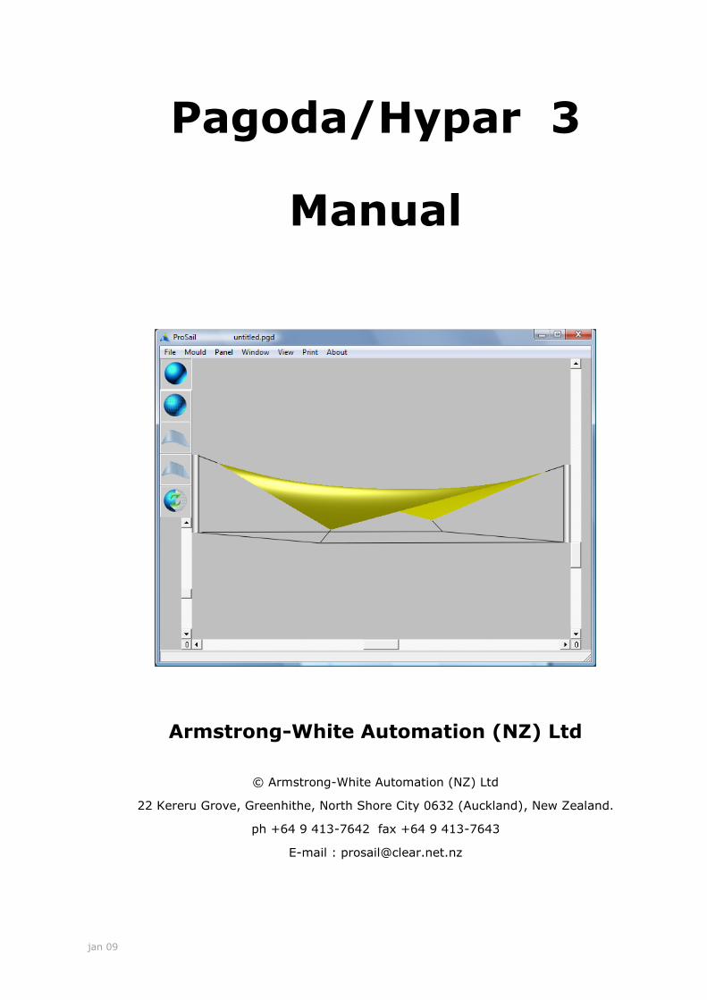
Pagoda/Hypar 3
Manual
Armstrong-White Automation (NZ) Ltd
© Armstrong-White Automation (NZ) Ltd
22 Kereru Grove, Greenhithe, North Shore City 0632 (Auckland), New Zealand.
ph +64 9 413-7642 fax +64 9 413-7643
E-mail : [email protected]
jan 09
2 ProSail
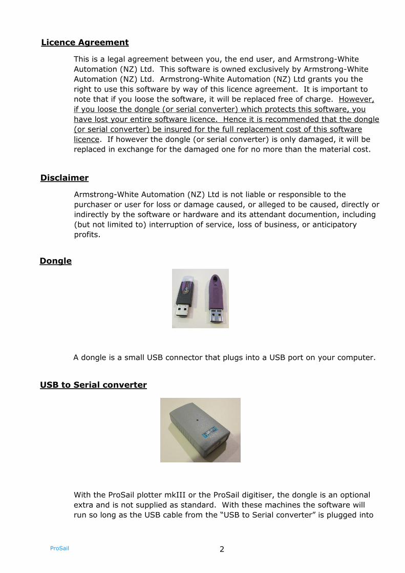
Dongle
A dongle is a small USB connector that plugs into a USB port on your computer.
Licence Agreement
This is a legal agreement between you, the end user, and Armstrong-White
Automation (NZ) Ltd. This software is owned exclusively by Armstrong-White
Automation (NZ) Ltd. Armstrong-White Automation (NZ) Ltd grants you the
right to use this software by way of this licence agreement. It is important to
note that if you loose the software, it will be replaced free of charge. However,
if you loose the dongle (or serial converter) which protects this software, you
have lost your entire software licence. Hence it is recommended that the dongle
(or serial converter) be insured for the full replacement cost of this software
licence. If however the dongle (or serial converter) is only damaged, it will be
replaced in exchange for the damaged one for no more than the material cost.
Disclaimer
Armstrong-White Automation (NZ) Ltd is not liable or responsible to the
purchaser or user for loss or damage caused, or alleged to be caused, directly or
indirectly by the software or hardware and its attendant documention, including
(but not limited to) interruption of service, loss of business, or anticipatory
profits.
USB to Serial converter
With the ProSail plotter mkIII or the ProSail digitiser, the dongle is an optional
extra and is not supplied as standard. With these machines the software will
run so long as the USB cable from the “USB to Serial converter” is plugged into
3 ProSail
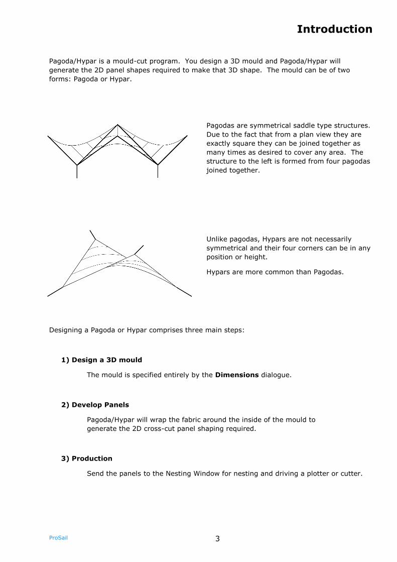
Pagoda/Hypar is a mould-cut program. You design a 3D mould and Pagoda/Hypar will
generate the 2D panel shapes required to make that 3D shape. The mould can be of two
forms: Pagoda or Hypar.
Pagodas are symmetrical saddle type structures.
Due to the fact that from a plan view they are
exactly square they can be joined together as
many times as desired to cover any area. The
structure to the left is formed from four pagodas
joined together.
Unlike pagodas, Hypars are not necessarily
symmetrical and their four corners can be in any
position or height.
Hypars are more common than Pagodas.
Designing a Pagoda or Hypar comprises three main steps:
1) Design a 3D mould
The mould is specified entirely by the Dimensions dialogue.
2) Develop Panels
Pagoda/Hypar will wrap the fabric around the inside of the mould to
generate the 2D cross-cut panel shaping required.
3) Production
Send the panels to the Nesting Window for nesting and driving a plotter or cutter.
Introduction
4 ProSail
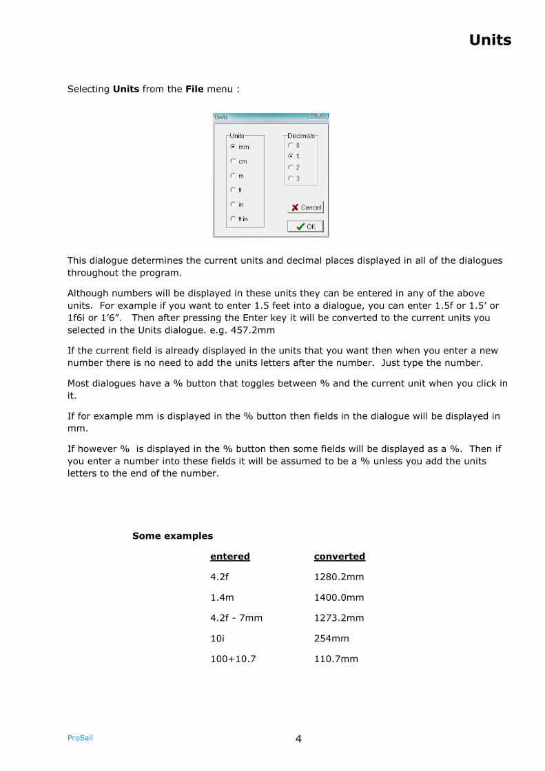
Units
Selecting Units from the File menu :
This dialogue determines the current units and decimal places displayed in all of the dialogues
throughout the program.
Although numbers will be displayed in these units they can be entered in any of the above
units. For example if you want to enter 1.5 feet into a dialogue, you can enter 1.5f or 1.5’ or
1f6i or 1’6”. Then after pressing the Enter key it will be converted to the current units you
selected in the Units dialogue. e.g. 457.2mm
If the current field is already displayed in the units that you want then when you enter a new
number there is no need to add the units letters after the number. Just type the number.
Most dialogues have a % button that toggles between % and the current unit when you click in
it.
If for example mm is displayed in the % button then fields in the dialogue will be displayed in
mm.
If however % is displayed in the % button then some fields will be displayed as a %. Then if
you enter a number into these fields it will be assumed to be a % unless you add the units
letters to the end of the number.
Some examples
entered converted
4.2f 1280.2mm
1.4m 1400.0mm
4.2f - 7mm 1273.2mm
10i 254mm
100+10.7 110.7mm
5 ProSail
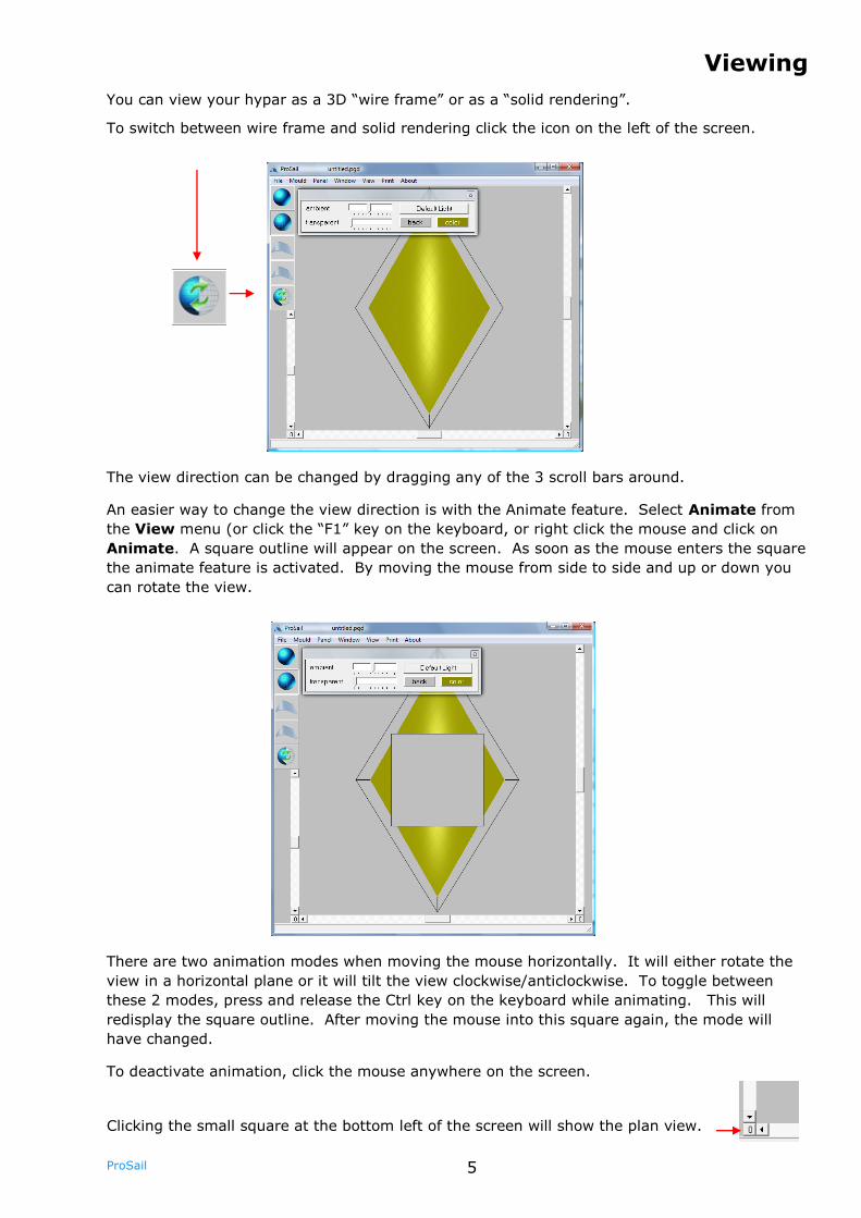
You can view your hypar as a 3D “wire frame” or as a “solid rendering”.
To switch between wire frame and solid rendering click the icon on the left of the screen.
Viewing
The view direction can be changed by dragging any of the 3 scroll bars around.
An easier way to change the view direction is with the Animate feature. Select Animate from
the View menu (or click the “F1” key on the keyboard, or right click the mouse and click on
Animate. A square outline will appear on the screen. As soon as the mouse enters the square
the animate feature is activated. By moving the mouse from side to side and up or down you
can rotate the view.
Clicking the small square at the bottom left of the screen will show the plan view.
There are two animation modes when moving the mouse horizontally. It will either rotate the
view in a horizontal plane or it will tilt the view clockwise/anticlockwise. To toggle between
these 2 modes, press and release the Ctrl key on the keyboard while animating. This will
redisplay the square outline. After moving the mouse into this square again, the mode will
have changed.
To deactivate animation, click the mouse anywhere on the screen.
6 ProSail
Light from : Click on this to animate the direction of the light source. Works in a
similar way to animating the view except it displays 2 arrows indicating
the direction of the light source. The arrows are largest when pointing
directly into the screen and change colour when at 90 degrees to this
direction.
There are actually 2 light sources - one directly in front which is fixed
and another one that you can change the direction of using Light
from.
toolbox : Displays the lighting toolbox. See next page.
View1, View1, View3, View4, View5 : Click on one of these to go to that stored
view. A quicker way is to use the “F2” key on the keyboard to loop
through the different views you have stored.
Store View : Up to 5 different views including different light settings for each can be
stored. Click Store View and select one of the 5 views to store the
current view.
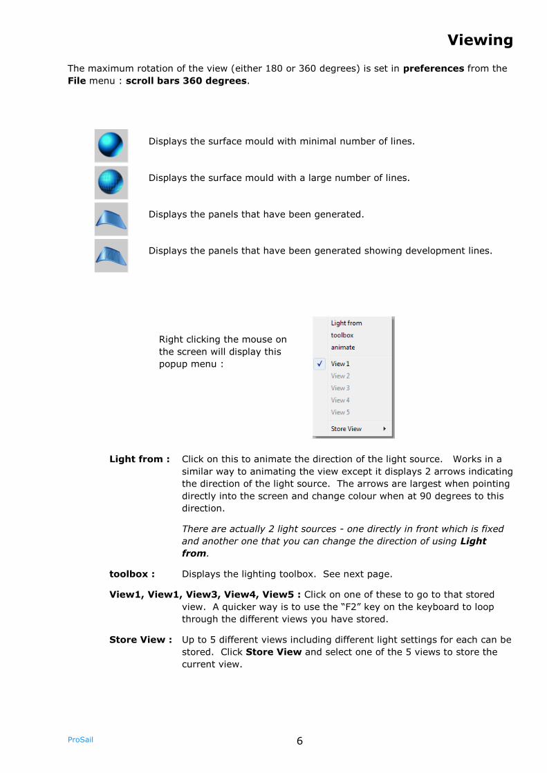
The maximum rotation of the view (either 180 or 360 degrees) is set in preferences from the
File menu : scroll bars 360 degrees.
Right clicking the mouse on
the screen will display this
popup menu :
Displays the surface mould with minimal number of lines.
Displays the surface mould with a large number of lines.
Displays the panels that have been generated.
Displays the panels that have been generated showing development lines.
Viewing
7 ProSail
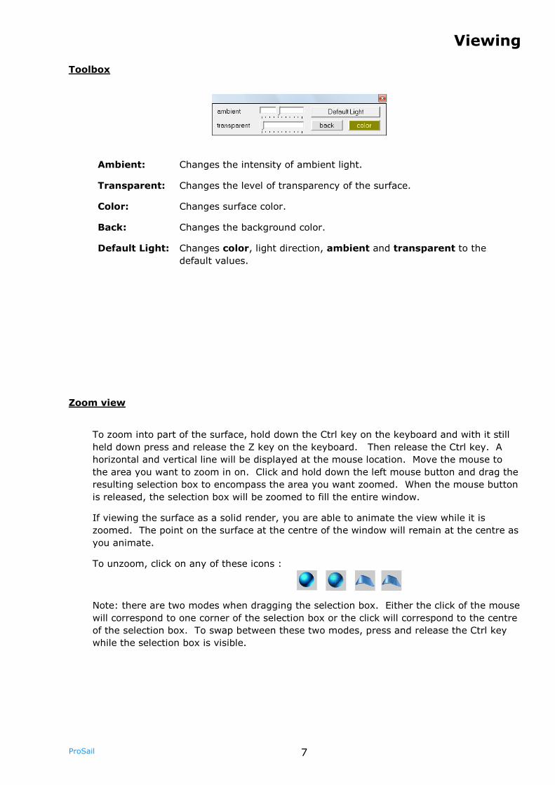
Ambient: Changes the intensity of ambient light.
Transparent: Changes the level of transparency of the surface.
Color: Changes surface color.
Back: Changes the background color.
Default Light: Changes color, light direction, ambient and transparent to the
default values.
Zoom view
To zoom into part of the surface, hold down the Ctrl key on the keyboard and with it still
held down press and release the Z key on the keyboard. Then release the Ctrl key. A
horizontal and vertical line will be displayed at the mouse location. Move the mouse to
the area you want to zoom in on. Click and hold down the left mouse button and drag the
resulting selection box to encompass the area you want zoomed. When the mouse button
is released, the selection box will be zoomed to fill the entire window.
If viewing the surface as a solid render, you are able to animate the view while it is
zoomed. The point on the surface at the centre of the window will remain at the centre as
you animate.
To unzoom, click on any of these icons :
Note: there are two modes when dragging the selection box. Either the click of the mouse
will correspond to one corner of the selection box or the click will correspond to the centre
of the selection box. To swap between these two modes, press and release the Ctrl key
while the selection box is visible.
Toolbox
Viewing
8 ProSail
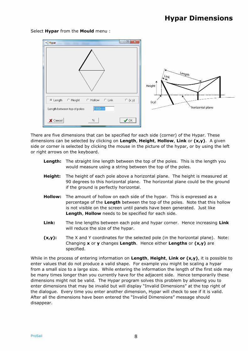
Select Hypar from the Mould menu :
Hypar Dimensions
There are five dimensions that can be specified for each side (corner) of the Hypar. These
dimensions can be selected by clicking on Length, Height, Hollow, Link or (x,y). A given
side or corner is selected by clicking the mouse in the picture of the hypar, or by using the left
or right arrows on the keyboard.
Length: The straight line length between the top of the poles. This is the length you
would measure using a string between the top of the poles.
Height: The height of each pole above a horizontal plane. The height is measured at
90 degrees to this horizontal plane. The horizontal plane could be the ground
if the ground is perfectly horizontal.
Hollow: The amount of hollow on each side of the hypar. This is expressed as a
percentage of the Length between the top of the poles. Note that this hollow
is not visible on the screen until panels have been generated. Just like
Length, Hollow needs to be specified for each side.
Link: The line lengths between each pole and hypar corner. Hence increasing Link
will reduce the size of the hypar.
(x,y): The X and Y coordinates for the selected pole (in the horizontal plane). Note:
Changing x or y changes Length. Hence either Lengths or (x,y) are
specified.
While in the process of entering information on Length, Height, Link or (x,y), it is possible to
enter values that do not produce a valid shape. For example you might be scaling a hypar
from a small size to a large size. While entering the information the length of the first side may
be many times longer than you currently have for the adjacent side. Hence temporarily these
dimensions might not be valid. The Hypar program solves this problem by allowing you to
enter dimensions that may be invalid but will display “Invalid Dimensions” at the top right of
the dialogue. Every time you enter another dimension, Hypar will check to see if it is valid.
After all the dimensions have been entered the “Invalid Dimensions” message should
disappear.
9 ProSail
Pagoda Dimensions
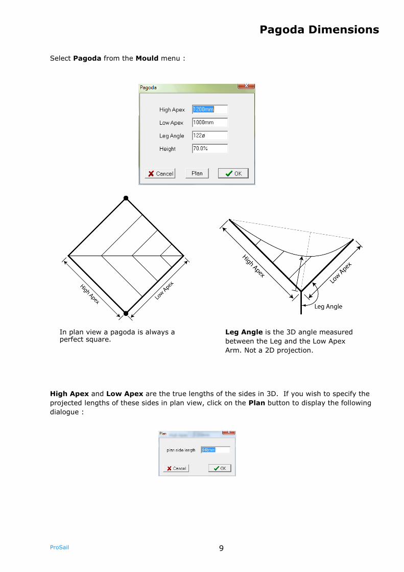
In plan view a pagoda is always a perfect square.
Select Pagoda from the Mould menu :
High Apex and Low Apex are the true lengths of the sides in 3D. If you wish to specify the
projected lengths of these sides in plan view, click on the Plan button to display the following
dialogue :
Leg Angle is the 3D angle measured
between the Leg and the Low Apex
Arm. Not a 2D projection.
10 ProSail
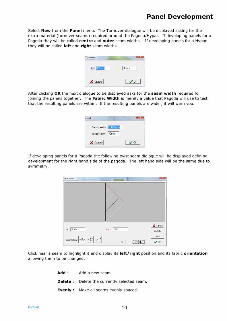
After clicking OK the next dialogue to be displayed asks for the seam width required for
joining the panels together. The Fabric Width is merely a value that Pagoda will use to test
that the resulting panels are within. If the resulting panels are wider, it will warn you.
If developing panels for a Pagoda the following twist seam dialogue will be displayed defining
development for the right hand side of the pagoda. The left hand side will be the same due to
symmetry.
Click near a seam to highlight it and display its left/right position and its fabric orientation
allowing them to be changed.
Add : Add a new seam.
Delete : Delete the currently selected seam.
Evenly : Make all seams evenly spaced.
Panel Development
Select New from the Panel menu. The Turnover dialogue will be displayed asking for the
extra material (turnover seams) required around the Pagoda/Hypar. If developing panels for a
Pagoda they will be called centre and outer seam widths. If developing panels for a Hypar
they will be called left and right seam widths.
11 ProSail
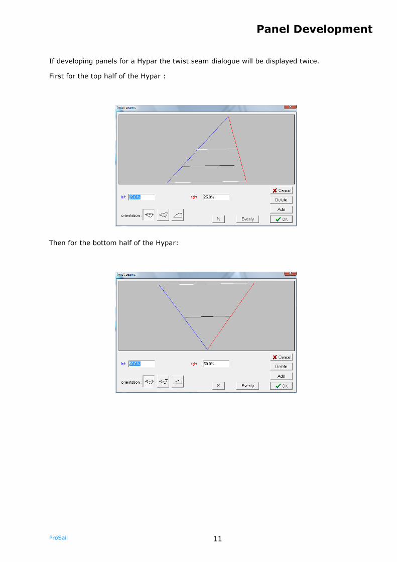
If developing panels for a Hypar the twist seam dialogue will be displayed twice.
First for the top half of the Hypar :
Then for the bottom half of the Hypar:
Panel Development
12 ProSail
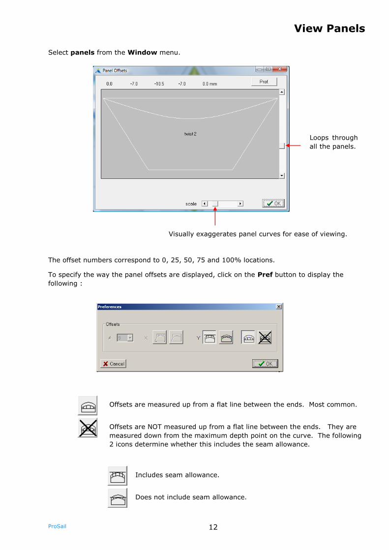
The offset numbers correspond to 0, 25, 50, 75 and 100% locations.
To specify the way the panel offsets are displayed, click on the Pref button to display the
following :
Select panels from the Window menu.
View Panels
Loops through
all the panels.
Visually exaggerates panel curves for ease of viewing.
Offsets are measured up from a flat line between the ends. Most common.
Does not include seam allowance.
Offsets are NOT measured up from a flat line between the ends. They are
measured down from the maximum depth point on the curve. The following
2 icons determine whether this includes the seam allowance.
Includes seam allowance.
13 ProSail
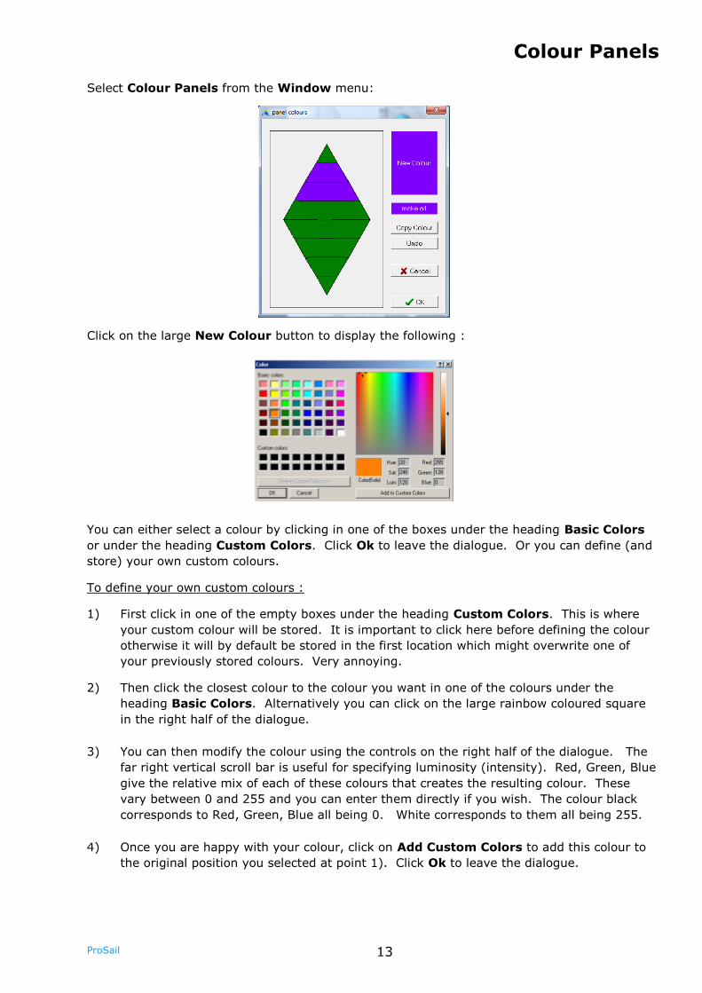
You can either select a colour by clicking in one of the boxes under the heading Basic Colors
or under the heading Custom Colors. Click Ok to leave the dialogue. Or you can define (and
store) your own custom colours.
To define your own custom colours :
1) First click in one of the empty boxes under the heading Custom Colors. This is where
your custom colour will be stored. It is important to click here before defining the colour
otherwise it will by default be stored in the first location which might overwrite one of
your previously stored colours. Very annoying.
2) Then click the closest colour to the colour you want in one of the colours under the
heading Basic Colors. Alternatively you can click on the large rainbow coloured square
in the right half of the dialogue.
3) You can then modify the colour using the controls on the right half of the dialogue. The
far right vertical scroll bar is useful for specifying luminosity (intensity). Red, Green, Blue
give the relative mix of each of these colours that creates the resulting colour. These
vary between 0 and 255 and you can enter them directly if you wish. The colour black
corresponds to Red, Green, Blue all being 0. White corresponds to them all being 255.
4) Once you are happy with your colour, click on Add Custom Colors to add this colour to
the original position you selected at point 1). Click Ok to leave the dialogue.
Select Colour Panels from the Window menu:
Click on the large New Colour button to display the following :
Colour Panels
14 ProSail
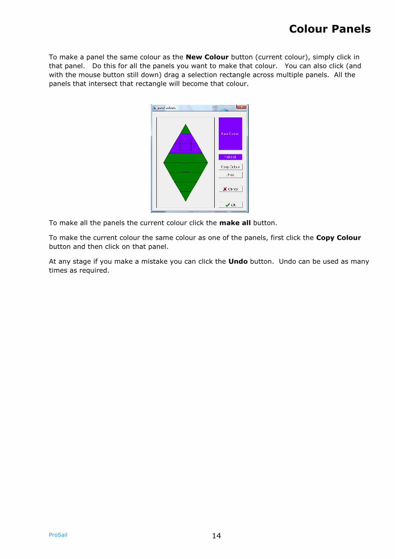
To make a panel the same colour as the New Colour button (current colour), simply click in
that panel. Do this for all the panels you want to make that colour. You can also click (and
with the mouse button still down) drag a selection rectangle across multiple panels. All the
panels that intersect that rectangle will become that colour.
To make all the panels the current colour click the make all button.
To make the current colour the same colour as one of the panels, first click the Copy Colour
button and then click on that panel.
At any stage if you make a mistake you can click the Undo button. Undo can be used as many
times as required.
Colour Panels
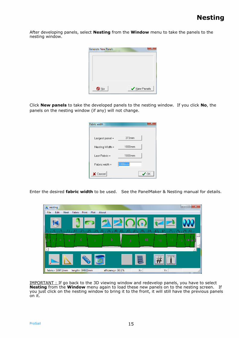
15 ProSail
Enter the desired fabric width to be used. See the PanelMaker & Nesting manual for details.
Nesting
After developing panels, select Nesting from the Window menu to take the panels to the nesting window.
Click New panels to take the developed panels to the nesting window. If you click No, the
panels on the nesting window (if any) will not change.
IMPORTANT : If go back to the 3D viewing window and redevelop panels, you have to select Nesting from the Window menu again to load these new panels on to the nesting screen. If you just click on the nesting window to bring it to the front, it will still have the previous panels on it.
16 ProSail
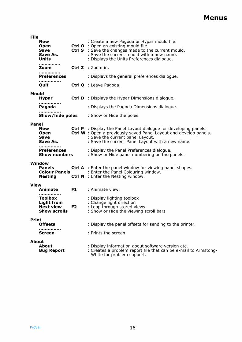
File New : Create a new Pagoda or Hypar mould file. Open Ctrl O : Open an existing mould file. Save Ctrl S : Save the changes made to the current mould. Save As. : Save the current mould with a new name. Units : Displays the Units Preferences dialogue. …………… Zoom Ctrl Z : Zoom in. …………… Preferences : Displays the general preferences dialogue. ............... Quit Ctrl Q : Leave Pagoda. Mould Hypar Ctrl D : Displays the Hypar Dimensions dialogue. ............... Pagoda : Displays the Pagoda Dimensions dialogue. ............... Show/hide poles : Show or Hide the poles. Panel New Ctrl P : Display the Panel Layout dialogue for developing panels. Open Ctrl W : Open a previously saved Panel Layout and develop panels. Save : Save the current panel Layout. Save As. : Save the current Panel Layout with a new name. ............... Preferences : Display the Panel Preferences dialogue. Show numbers : Show or Hide panel numbering on the panels. Window Panels Ctrl A : Enter the panel window for viewing panel shapes. Colour Panels : Enter the Panel Colouring window. Nesting Ctrl N : Enter the Nesting window. View Animate F1 : Animate view. ............... Toolbox : Display lighting toolbox Light from : Change light direction Next view F2 : Loop through stored views. Show scrolls : Show or Hide the viewing scroll bars Print Offsets : Display the panel offsets for sending to the printer. ............... Screen : Prints the screen. About About : Display information about software version etc. Bug Report : Creates a problem report file that can be e-mail to Armstong-
White for problem support.
Menus