Embed Size (px)
Citation preview


New
absolute filter elements
independently tested
in the following Institutes:
MPTMPT series filters are designed for return lines, and
are installed semi-immersed in a reservoir.
The MPT series are available with an air breather
designed into the head of the filter assembly.
Continued Research and Development on both the
filter bodies and the filter elements has resulted in
a product line with excellent pressure drop charac-
teristics combined with a high filtration efficiency.
The high flow rate bypass valves is a standard fea-
ture with this range of product.
MPT filters within this range are suitable for flow
rates up to 40 gpm.
MPT series are specifically designed for use on
small industrial power units, and mobile
applications.
D e s c r i p t i o n
MPT 02040/7.99/USA 2
PRESSURE DIE CASTALUMINIUM
TANK FLANGE O-RING
INDICATOROPTIONS
VISUALREMOVAL HANDLE
COVER
NYLON BOWL
FULLY RESPONSIVEBYPASS VALVE
HIGH EFFICIENCY ELEMENT WITH HIGH
DIRT HOLDING CAPACITY
FILTER ELEMENT LENGTH OPTIONS
CAPTIVE O-RING SEAL
AIR BREATHEROPTION
STANDARDANTI-SPLASH
BAFFLE
OPTIONALEXTENSION
TUBE
UNI EN ISO 9001N° 037/98
È
È
ELECTRICAL

Element materialNominal filtration
Inorganic microfiber with acrylic support
A Series
Resin - impregnated paper
P Series
New improved ß ≥ 200filter elements withgreater efficiency andincreased dirt holding capacity
Contamination retentionas per ISO 4572: Multi-pass test.
Filtering area Filter elements “H” collapse - ∆P=145 psi
Filtering areaFilter elements “N” collapse - ∆P=45 psi
Square wire mesh (filtration degree is definedin microns by the maximum diameter of asphere corresponding to the mesh size)
M Series
Element materialAbsolute filtration
MP Filtr i - Fi ltration technology
3
∆ P(psi)ß ≥ 2
(50%)ß ≥ 20(95%)
ß ≥ 75(98,7%)
ß2 ß10 ß20
ß ≥ 200(99,5%)
Dimensions for ß (µm) valuesFilter
elements
A03
A06
A10
A25
–
–
3
13
2
3
6
19
2,4
4,6
7,8
22
3
6
10
25
> 10.000
> 2.000
≥ 200
> 1,5
> 10.000
> 10.000
> 10.000
> 35
100
100
100
100
20
8
1,5
–
Filtration ratios
N.B. Other materials giving different degrees of filtration are available on request.
Values in sq in
Values in sq in
Type MF
A03/A06
A10/A25
020-1
65
65
020-2
122
122
020-3
155
155
100-1
97,7
97,7
100-2
155
155
100-3
268
268
Type MF
P10/P25
M25
M60
M90
020-1
77.5
63.5
63.5
63.5
020-2
136
111.6
111.6
111.6
020-3
170.6
140
140
140
100-1
158.0
71.3
71.3
71.3
100-2
257.3
113.2
133.2
113.2
100-3
295
194
194
194
Materials
ISO 2941 - Verification of collapse/burst resistance.
ISO 2942 - Verification of fabrication integrity and determination
of the first bubble point.
ISO 2943 - Verification of material compatibility with fluids.
ISO 3723 - Method for end load test.
ISO 3724 - Verification of flow fatigue characteristics.
ISO 3968 - Evaluation of pressure drop versus flow characteristics.
ISO 4572 - Multi-pass method for evaluating filtration performance.
MP Filter elements - Conform to the following ISO standards
External wire mesh
Microfiber filtration mediaInternal wire mesh
Inner supporttube
External support media
Internal support media
End caps:Nylon
Support tube:Galvanized steel
Support frames:Galvanized steel with an epoxy coating
A SeriesInorganic microfiber
Filter element:

water - glycol (types HFC as per ISO 6743/4)
V SeriesViton compatible with synthetic fluids(types HS-HFDR-HFDS-HFDU as per ISO 6743/4)
Bypass valve
SealsA Series: Nitrile (Buna-N)V Series: Viton
Filter head and bowlscompatible for use with:• mineral oils
(types HH-HL-HM-HR-HV-HG as per ISO 6743/4)• water-based emulsions
(types HFAE-HFAS as per ISO 6743/4)• synthetic fluids
(types HS-HFDR-HFDS-HFDU as per ISO 6743/4)• water-glycol
(types HFC as per ISO 6743/4)Ask for anodised version
VR SeriesVisual indicator
Color coded pressure gaugescale 0-30 psi
Collapse pressurefilter elements
M P F i l t r i - S p e c i f i c a t i o n
N Series 45 psiH Series 145 psi
From -13°F to 230°FFor temperatures outside this range, please consult our Sales and Network Organization
Workingtemperature
Fatigue test: a filter body subjected to pressure impulses from 0 to 100 psi will withstand 1.000.000 cycles
Pressure filterbody Maximum working pressure up to 100 psi
Test pressure: 145 psiMinimum burst pressure: 290 psi
B: 25 psi ± 10%Bypass valve, differential opening pressure:Bypass valveCalibration pressure
15 psi ± 10%
Description:All styles set to indicate an element change at:
Types of indicators
Materials
Pressure die cast aluminium
CoverNylon
Nylon
Head
Electrical indicatorOperational information:Max voltage: 48 Vac 50÷60 HzMax current: 0.5 A resistive, 0.2 A inductive.
ER Series:Pressure switch with N.O. contactsEC Series:Pressure switch with N.C. contacts
Compatibilitywith fluids
Brass
Nylon
BowlIndicator
SealsA SeriesNitrile (Buna-N) compatible with mineral oils(types HH-HL-HM-HR-HV-HG as per ISO 6743/4)water - based emulsions(types HFAE-HFAS as per ISO 6743/4)
Filter elementsAs per ISO 2943; suitable for mineral oils(types HH-HL-HM-HR-HV-HG as per ISO 6743/4) synthetic fluids (A and M series only)(types HS-HFDR-HFDS-HFDU as per ISO 6743/4)
For water-based emulsions (types HFAE-HFAS as per ISO 6743/4) and fluids other than those mentioned, please consult our Sales and Network Organization.
4
Filter body:

Absolute inorganic microfiberfiltration media, available in3, 6, 10 and 25 micronExample - A03, A06, A10 or A25
Filter elementstypes
A Series P SeriesNominal cellulose impregnatedpaper media, available in 10 and 25 micron.Example - P10 or P25
M SeriesMetal mesh media, available in25, 60, and 90 micron.Example - M25, M60 or M90.
Please refer to individual pressure drop curves to obtain filter element pressure drop information
The following filter sizing recommendations are based using a mineral oil fluid 150 SUS with a maximum total filter assembly (housingand filter element) pressure drop of 30% of the filter condition indicator (5.8 psi)
5
MPT SERIES 020 SIZE
Thread connections
MPT 020
Type
G1
G2
G3
G4
G5
G6
G7
G8
G9
A
3/8” BSP
1/2” BSP
Not available
3/8” NPT
1/2” NPT
Not available
SAE 6 - 9/16” - 18 UNF
SAE 8 - 3/4” - 16 UN
Not available
* Flow rates with 150 SUS fluid** Weight including filter element
Filterassembly
Flow rategpm *
Bowllength
Port sizeBSP/NPT/SAE
Weightlb
**A03
A06
A10
A25
P10
A03
A06
A10
A25
P10
A03
A06
A10
A25
P10
4,5
5,8
7,9
9,2
9,2
5,3
6
9,2
12
12
7,9
9,2
13,2
21,1
21,1
1
2
3
3/8”
3/8”
1/2”
3/8”
1/2”
0.66
0.88
1.1
Type
1
2
3
H
4
6.49
8.26
H1
4.52
7.1
8.26
LenghtsØ 2.4
1.892.36
1.81
Standard baffleØ 2,36
Ø 1,06
Ø 2
Ø 2,95
3/8 UNC
R 0.45
R 0.21
3.3
- 3
.46
2,4
4H
1
A
0.82
0,94
3.3
3.4
6
H
Mounting patternWith air breather
Without air breather
1.02
ø 1.57
ø1.18
A/F14 (mm)
1/8” NPT1/8” NPT
Pg 0.27
2.2
1.69
1.22
A/F24 (mm)
Select ion & insta l lat ion in fo rmat ion
Housing pressure dropMPT 020
Flow rate gpm
∆p p
si
70 14 21 28 35
1/2”6
4
2
0

S e l e c t i o n& i n s t a l l a t i o n i n f o r m a t i o n
6
Please refer to individual pressure drop curves to obtain filter element pressure drop information
The following filter sizing recommendations are based using a mineral oil fluid at 150 SUS with a maximum total filter assembly (housingand filter element) pressure drop of 30% of the filter condition indicator (5.8 psi)
Thread connections
MPT 100
* Flow rates with 150 SUS fluid** Weight including filter element
Filterassembly
Flow rategpm*
Bowllength
Port sizeBSP/NPT/SAE
Weightlb
**A03
A06
A10
A25
P10
A03
A06
A10
A25
P10
A03
A06
A10
A25
P10
6,6
7,9
9,2
17,1
13,2
8,4
10
11,8
33
26,4
11,8
14,5
18,5
39,5
33
1
2
3
3/4”
3/4”
1”
1”
1 1/4”
2,2
2,64
2,86
Type
G1
G2
G3
G4
G5
G6
G7
G8
G9
A
3/4” BSP
1” BSP
1 1/4” BSP
3/4” NPT
1” NPT
1 1/4” NPT
SAE 12 - 1 1/16” - 12 UN
SAE 16 - 1 5/16” - 12 UN
SAE 20 - 1 5/8” - 12 UN
C
1/8” BSP
1/8” BSP
1/8” BSP
1/8” NPT
1/8” NPT
1/8” NPT
1/8” NPT
1/8” NPT
1/8” NPT
Type
1
2
3
H
3,98
5,7
8,85
H1
3,93
5,7
9,05
ø B
1.14
1.14
1.69
Lengths
Mounting pattern
Ø 3,4 min
Ø 4,37Ø 3,38
Ø BØ 3,15
Ø 0,35
1,02
Ø 0
,78
4,5
6
2,1
24
,57
1,8
83,7
4H
1H
A
1.2
6
0.95
1.5
7
2,32
C
2,67
2,792,99
4,25
R 0.45
for
air
brea
ther
onl
y
Ø 3,5 max5/16 UNC
With air breather
Without air breather
1.22
2.20
Pg 0,27
ø 1,1
8
1,69
1,34 ø 1,57
A/F 24(mm)
A/F14(mm)
1/8”
NPT
1/8”
NPT
MPT SERIES 100 SIZE
Housing pressure dropMPT 100
Flow rate gpm
∆p p
si
**120 24 36 48 60
1”
3/4”
1 1/4”
6
4
2
0
�
�

• Customer requires a 16 gpm filter assembly
• Mineral oil fluid: 340 SUS at 104°F
• A25 - 25 micron absolute filtration
Selection :
•Housing pressure drop - MPT 100 (1” BSP or NPT option) with 16 gpm ∆p = 0.2 psi (see curve on page 6)
•Filter element pressure drop (brochure viscosity) - MF 100.2.A25HB with 16 gpm ∆p = 2.3 psi (see curve on page 8)
•Filter element pressure drop (working viscosity) - With 340 SUS ∆p1 = 2.3 x (340/150) = 5.21 psi
•Filter assembly pressure drop ∆p Total = ∆p Housing + ∆p1 Filter element = 0.2 + 5.21 = 5.41 psi* { Acceptable pressure drop value,as per our recommendations
The curves were obtained using a mineral oil with a density of 0,86.The ∆p varies proportionally to the density.
GeneralPressure drop versus flow rate curve information for both housing and filter elements is in accordance with ISO 3968
Filter assembly pressure drop - ∆p Total = ∆p Housing + ∆p Filter element
Housing pressure drop - The housing pressure drop is proportional to the fluid density
Filter element pressure drop - Filter element pressure drop is proportional to kinematic viscosity therefore always check thefluid operating temperature and fluid type to obtain the working viscosity according to the following formula:
P r e s s u r e d r o p i n f o r m a t i o n
Fi l ter assembly s iz ing example
B y p a s s v a l v e s p r e s s u r e d r o p
7
Brochure viscosity 150 SUS
∆p1 Filter element = (working viscosity/brochure viscosity) x ∆p filter element
Flow rate gpm
∆p p
si
MPT 020
0 6 12 18 24
60
40
20
0
Flow rate gpm
∆p p
si
MPT 100
0 10 20 30 40
60
40
20
0

8
The curves were obtained using a mineral oil with a kinematic viscosity of 150 SUS.The ∆p varies proportionally to the fluid kinematic viscosity.
For the metal mesh filter elements curves (M series), please consult our Sales and Network Organization
The curves were obtained using a mineral oil with a kinematic viscosity 150 SUS.The ∆p varies proportionally to the fluid kinematic viscosity.
Filter elements - N - ∆P 45 psi
Filter elements - H - ∆P 145 psi
Flow rate gpm
∆p p
si
MF 020 - 1 P...N
4 8 12 16
P10
P25
0
6
4
2
0
Flow rate gpm
∆p p
si
MF 020 - 1 A...H
4 8 12 16
A03 A06A10
A25
0
15
10
5
0
Flow rate gpm
∆p p
si
MF 100 - 1 A...H
10 20 30 40
A03A06
A10
A25
0
15
10
5
0
Flow rate gpm
∆p p
si
MF 100 - 2 A...H
10 20 30 40
A03 A06A10
A25
0
15
10
5
0
Flow rate gpm
∆p p
si
MF 100 - 3 A...H
10 20 30 40
A03 A06A10
A25
0
15
10
5
0
Flow rate gpm
∆p p
si
MF 020 - 2 A...H
4 8 12 16
A03 A06
A10
A25
0
15
10
5
0
Flow rate gpm
∆p p
si
MF 020 - 3 A...H
6 12 18 24
A03
A06
A10A25
0
15
10
5
0
Flow rate gpm
∆p p
si
MF 100 - 1 P...N
10 20 30 40
P10
P25
0
15
10
5
0
Flow rate gpm
∆p p
si
MF 100 - 2 P...N
10 20 30 40
P10
P25
0
15
10
5
0
Flow rate gpm
∆p p
si
MF 100 - 3 P...N
10 20 30 40
P10
P25
0
15
10
5
0
Flow rate gpm∆p
psi
MF 020 - 2 P...N
4 8 12 16
P10
P25
0
6
4
2
0
Flow rate gpm
∆p p
si
MF 020 - 3 P...N
4 8 12 16
P10
P25
0
6
4
2
0
*

The filter element has a handle on the top allowing easyremoval from the bowl.
The helical spring is utilized to secure the filter element in its location.
Fi l te r e lement r ep lacement
Appl icat ions
Example of application
9
Extension tube option:
Special application filters on request
HOW TO SPECIFY AN EXTENDED TUBE IN AN ASSEMBLY PART NUMBER
1) Determine the “H” dimension in millimeters (including the tube) you will require2) Divide this number by 10 and add the answer after a slash (/) at the end of the assemblypart number.NOTE: The “H” dimension can only be specified in multiplest of 10 millimeters and issubject to the minimum lengths listed below.EXAMPLE: For a MPT1001AG4A10HBT filter assembly with “H” dimension of 200 millimetersthe final par t number would look this: MPT1001AG4A10HBT/20
MINIMUM LENGTHSMPT020-1: 160mm / 6.29 inMPT020-2: 270mm / 10.63 inMPT020-3: 310mm / 12.20 inMPT100-1: 200mm / 7.87 inMPT100-2: 250mm / 9.84 inMPT100-3: 330mm / 12.99 in

10
Notes
G1
G2
G3
G4
G5
G6
G7
G8
G9
3/8” BSP
1/2” BSP
–
3/8” NPT
1/2” NPT
–
SAE 6
SAE 8
–
3/4” BSP
1” BSP
1 1/4” BSP
3/4” NPT
1” NPT
1 1/4” NPT
SAE 12
SAE 16
SAE 20
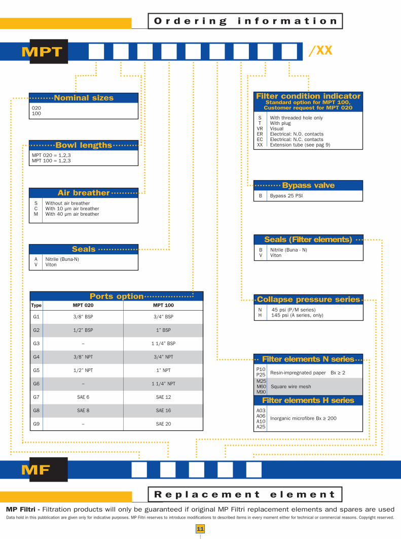
Ports optionType MPT 020 MPT 100
11
S With threaded hole onlyT With plug
VR Visual ER Electrical: N.O. contactsEC Electrical: N.C. contactsXX Extension tube (see pag 9)
P10 Resin-impregnated paper Bx ≥ 2P25
M25M60 Square wire meshM90
MP Filtri - Filtration products will only be guaranteed if original MP Filtri replacement elements and spares are usedData hold in this pubblication are given only for indicative purposes. MP Filtri reserves to introduce modifications to described items in every moment either for technical or commercial reasons. Copyright reserved.
A03A06 Inorganic microfibre Bx ≥ 200A10A25
A Nitrile (Buna-N)V Viton
O r d e r i n g i n f o r m a t i o n
R e p l a c e m e n t e l e m e n t
MPT
MF
020100
Nominal sizes
Bowl lengths
Seals
S Without air breatherC With 10 µm air breatherM With 40 µm air breather
Air breather
Filter elements N series
Filter elements H series
Seals (Filter elements)
/XX
B Nitrile (Buna - N) V Viton
Filter condition indicatorStandard option for MPT 100,Customer request for MPT 020
Collapse pressure series
MPT 020 = 1,2,3MPT 100 = 1,2,3
N 45 psi (P/M series)H 145 psi (A series, only)
Bypass valveB Bypass 25 PSI

Head Quarter :MP FILTRI S.p.A. ItalyVia Matteotti, 220060 Pessano con Bornago (Milano) ItalyTel. ++39.02/95703.1Fax ++39.02/95741497-95740188email: [email protected]://www.mpfiltri.com
GREAT BRITAINMP FILTRI U.K. Ltd.Bourton Industrial ParkBourton on the WaterGloucestershire GL54 2HQ UKPhone: 01451-822522Fax: 01451-822282email: [email protected]://www.mpfiltri.co.uk
GERMANYMP FILTRI D GmbHAm Wasserturm 5D-66265 Heusweiler/HolzPhone: 06806/85022-0Fax: 06806/85022-18email: [email protected]
U.S.A.:MP FILTRI U.S.A. Inc.1256C Oakbrook Drive - Norcross,Georgia - U.S.A. 30093Phone: 770-263-0090Fax: 770-242-4069email: [email protected]
CANADA:MP FILTRI CANADA Inc.210 Jacob Keffer Parkway Concord,Ontario Canada L4K 4W3Phone: 905-303-1369Fax: 905-303-7256email: [email protected]://www.mpfiltricanada.com
®