Embed Size (px)
Citation preview
MPS/MST
Flow rates to 300 l/min
Maximum working pressure 12 bar
SPIN - ON FILTER SUCTION - RETURN
®
SERIES
New
absolute filter elements
independently tested
in the following Institutes:
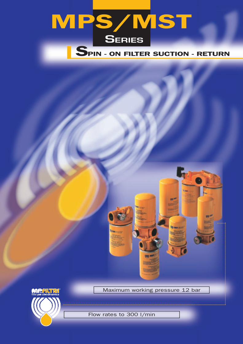
MPS/MSTThe MPS spin-on filter series is a complete productrange suitable, for both suction and returnapplications. Utilising spin-on canisters, the MPSseries are quick and easy to service and provide a‘clean’ solution when changing elements.The filter elements are either resin-impregnated paper(ßx>2), glass fibre (ßx≥200) or square wire mesh.The unique filter head is designed for both European CSand American CG standard canister series. One headdesign series accomodates both styles of elements.Also available is a new design utilizing a pressuredifferential visual and electrical indicators - ideal forlubrication applications.MPS filters are specifically designed forcontamination control in hydraulic and lubricationcircuits for mobile applications, agricultural andmachine tool systems.
The CW series of canister removes water from oilwhile filtering the oil at the same time.Water absorbent polymers up to 800 times theirown weight, provide this major feature.Water holding capacities: - CW 050 - 240 ml. CW 150 - 788 ml.
D e s c r i p t i o n
MPS 050/3.2000/UK 2
UNI EN ISO 9001N° 037/98
DIFFERENTIAL INDICATORSFor Use with series “1”filter heads.
SUCTION INDICATORS
VISUAL
VISUAL
RETURN LINE INDICATORS
ELECTRICAL
ELECTRICAL
For Use with series “0”filter head.

Element materialNominal filtration
Inorganic microfibre with acrilic support
A Series
Resin - impregnated paper
P Series
New improved ß ≥ 200filter elements withgreater efficiency andincreased dirt holding capacity
Contamination retentionas per ISO 16889: Multi-pass test.
Filtering area Filter elements
Filtering areaFilter elements
Square wire mesh (filtration degree is definedin microns by the maximum diameter of asphere corresponding to the mesh size)
M Series
Resin - impregnated paper
CWSeries
Element materialAbsolute filtration
MP Filtr i - Fi ltration technology
3
∆ P(bar)ß ≥ 2
(50%)ß ≥ 20(95%)
ß ≥ 75(98,7%)
ß2 ß10 ß20
ß ≥ 200(99,5%)
Dimensions for ß (µm) valuesFilter
elements
A03
A06
A10
A25
–
–
3
13
2
3
6
19
2,4
4,6
7,8
22
3
6
10
25
> 10.000
> 2.000
≥ 200
> 1,5
> 10.000
> 10.000
> 10.000
> 35
7
7
7
7
20
8
1,5
–
Filtration ratios
N.B. Other materials giving different degrees of filtration are available on request.
Values in cm2
Values in cm2
TypeCS-CG-CT
A03/A06
A10/A25
050
1900
1900
070
3160
3160
100
3950
3950
150
5390
5390
Type
CS-CG-CT
P10/P25
M25
M60
M90
050
2440
1000
1000
1000
070
4140
1270
1270
1270
100
4300
1990
1990
1990
150
5760
2400
2400
2400Type CW
P10/P25
050
2000
150
3050
Materials
ISO 2941 - Verification of collapse/burst resistance.
ISO 2942 - Verification of fabrication integrity and determination
of the first bubble point.
ISO 2943 - Verification of material compatibility with fluids.
ISO 3723 - Method for end load test.
ISO 3724 - Verification of flow fatigue characteristics.
ISO 3968 - Evaluation of pressure drop versus flow characteristics.
ISO 16889 - Multi-pass method for evaluating filtration performance.
MP Filter elements - Conform to the following ISO standards
External wire mesh
Microfibre filtration mediaInternal wire mesh
Inner supporttube
Pre-filtration andExternal support media
Internal support media
End caps:Galvanized steel
Support tube:Galvanized steel
Support frames:Galvanized steel withan epoxy coating
A SeriesInorganic microfibre
Filter element:

Bypass valveNylon
Collapse pressurefilter elements
M P F i l t r i - S p e c i f i c a t i o n
From -25 to +110°CFor temperatures outside this range, please consult our Sales Network Organization
Workingtemperature
12 bar
4 bar
Pressure filterbody Maximum working pressure up to
S series: 0,3 bar ± 10% (MPS series only)R series: 1,75 bar ± 10%
Bypass valve, differential opening pressure:Bypass valveCalibration pressure
Materials
1 Kpa = 0.01 barDescription:MPS series filters are fitted with indicators switching:Suction filters at a pressure of: 20 kPa ± 10%Line filters at a pressure of: 1,3 bar ± 10% (MPS series only)Return filter at a pressure of: 1,3 bar ± 10% (MPS-MST series only)
Types of indicators for MPS series “0” (MPS 050-070-100…) and MST series
Electrical indicatorOperational information:
Switching at 20kPa ± 10%Max voltage: 250V 50÷60 HzMax current: 5 A resistive, 2 A inductiveProtection degree IP65
Switching at 1,3 bar ± 10%Max voltage: 48V 50÷60 HzMax current: 0,5A resistive
0,2A inductive
Suction filter (MPS series only)E0 Vacuum switch with change over contact
Return filterER Pressure switch with N.O. contactsEC Pressure switch with N.C. contacts
Suction filter: (MPS series only)VS vacuum switch scale 0 - 76 cm Hg
Return and line filterVA Pressure gauge scale 0 - 12 barVR colour coded pressure gauge scale 0 - 6 bar
Visual indicator
MPS filter series 1 (051-071-101… and so on)are fitted with, differential style indicators.
Types of indicators for MPS series “1” (MPS 051-071-101-151-301-351)
Electrical indicator
1V - Z1 Series for Filter with bypass set switching at 1,2 bar ± 10%to 1,75 bar
V6 - Z6 Series for Filter without bypass switching at 2 bar ± 10%
N1 Series for Filter with bypass set switching at 1,2 bar ± 10%to 1,75 bar
N6 Series for Filter without bypass switching at 2 bar ± 10%Visual-electricalindicator 1E - K1* Series for Filter with bypass set switching at 1,2 bar ± 10%
to 1,75 barE6 - K6* Series for Filter without bypass switching at 2 bar ± 10%
Visual indicator
4
HeadAluminium
SealsA Series: Nitrile (Buna-N)V Series: Viton
IndicatorBrass
*For K visual-electrical indicator, specify the voltage (il. K61 = LED: 24 volt) { 1 - 24 Volt2 - 115 Volt3 - 230 Volt
*

Pressure differential indicator option
M P F i l t r i - S p e c i f i c a t i o n
5
ELECTRICAL CONNECTION K SERIES
ELECTRICAL CONNECTION E - N SERIES
CONNECTOR DIN 43650
Electrical N series
Ø16
G1/2”
Ø16
G1/2”
A/F 32A/F 30
28
41 35
27
69
Visual V series Visual Z series
A/F 30
38
27
65
G1/2”
Ø16
Visual - Electrical E series
A/F 32
38,5
28
76
G1/2”
Ø16
Visual led - Electrical K series
A/F 30
38
Led
27
65
G1/2”
Ø16
N.C.
N.O.
N.C.
N.O.
(A)
2
2
3
0,03
0,03
(A)
5
5
5
0,5
0,25
(V)
Vca 125
Vca 250
Vcc 30
Vcc 125
Vcc 250
Resistive load Inductive loadSupply voltage (50/60 Hz)
K - E - N Series

M P F i l t r i - S p e c i f i c a t i o n
water-based emulsions(types HFAE-HFAS as per ISO 6743/4)water - glycol (types HFC as per ISO 6743/4)V SeriesViton compatible with synthetic fluids(types HS-HFDR-HFDS-HFDU as per ISO 6743/4)
Filter head and bowlscompatible for use with:• mineral oils
(types HH-HL-HM-HR-HV-HG as per ISO 6743/4)• water-based emulsions
(types HFAE-HFAS as per ISO 6743/4)• synthetic fluids
(types HS-HFDR-HFDS-HFDU as per ISO 6743/4)• water-glycol (types HFC as per ISO 6743/4)
FluidCompatibility
SealsA SeriesNitrile (Buna-N) compatible with mineral oils(types HH-HL-HM-HR-HV-HG as per ISO 6743/4)
Filter elementsAs per ISO 2943; suitable for mineral oils(types HH-HL-HM-HR-HV-HG as per ISO 6743/4) and synthetic fluids (A and M series only)(types HS-HFDR-HFDS-HFDU as per ISO 6743/4)For water-based emulsions (types HFAE-HFAS as per ISO 6743/4) and fluids other than those mentioned, please consult our Sales Network Organization.
6
International standards for contamination fluid control
Contamination Correspondent Recommended Typical applicationscodes codes filtration
ISO 4406 NAS 1638 degree
4µm(c) 6µm(c) 14µm(c) B x ≥ 200
14 12 9 3 3 High precision andlaboratory servo-systems
17 15 12 6 3-6 Robotic and servo-systems
18 16 13 7 10-12 Very sensitive - highreliability systems
20 18 15 9 12-15 Sensitive - reliable systems
21 19 16 10 15-25 General equipment oflimited reliability
23 21 18 12 25-40 Low - pressure equipmentnot in continuous service
A general (no direct) comparison between ISO 4406 and NAS 1638 is given in table below.
A
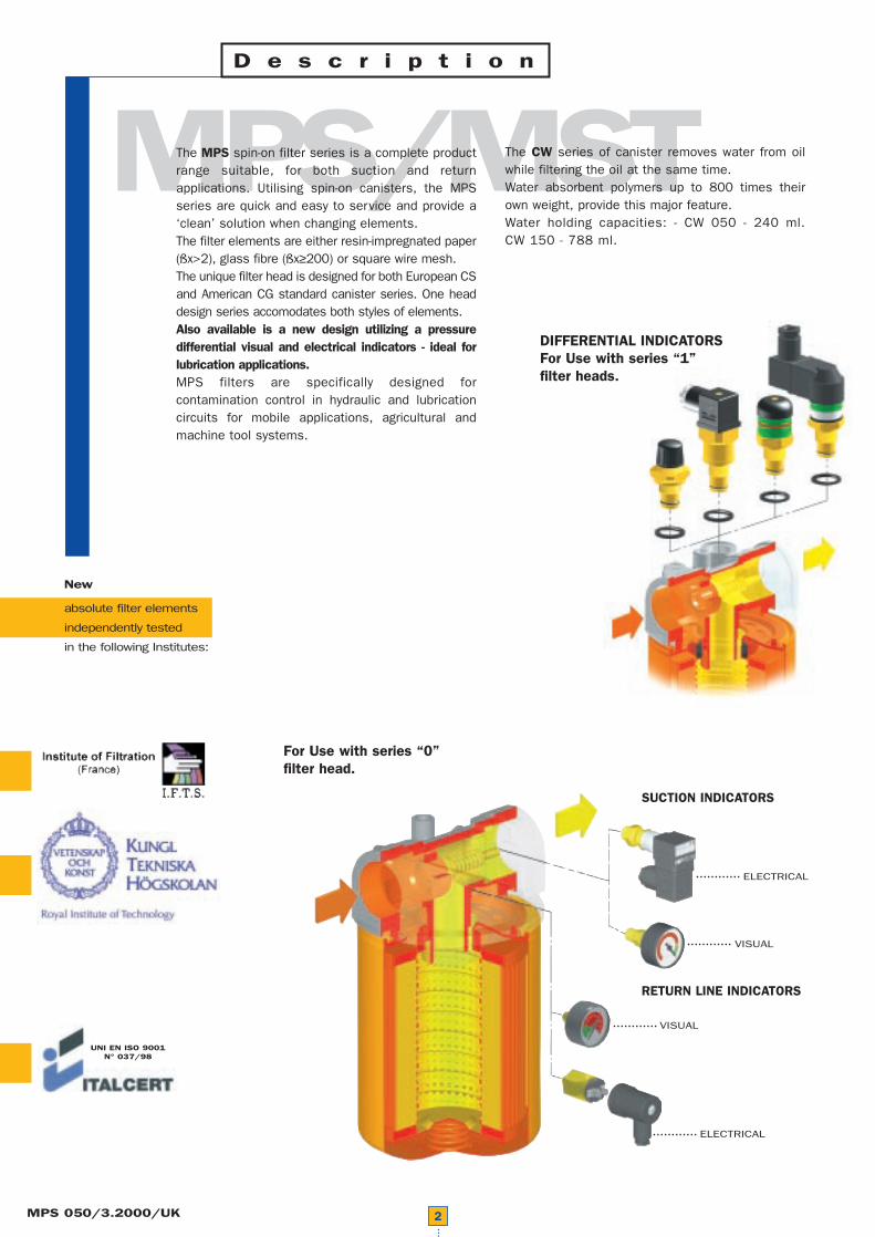
Absolute inorganic microfibrefiltration media, available in3, 6, 10 and 25 micronExample - A03, A06, A10 or A25
S e l e c t i o n& i n s t a l l a t i o n i n f o r m a t i o n
Filter elementstypes
A Series P SeriesNominal cellulose impregnatedpaper media, available in 10 and 25 micron.Example - P10 or P25
M SeriesMetal mesh media, available in25, 60, and 90 micron.Example - M25, M60 or M90.
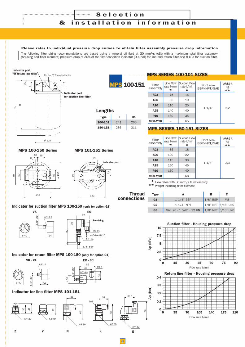
Please refer to individual pressure drop curves to obtain filter assembly pressure drop information
The following filter sizing recommendations are based using a mineral oil fluid at 30 mm2/s (cSt) with a maximum total filter assembly (housing and filter element) pressure drop of 30% of the filter condition indicator (0.4 bar) for line and return filter and 8 kPa for suction filter.
7
MPS SERIES 050-051 SIZES
Thread connections
MPS 050-071
Type
G1
G2
G3
G4
G5
G6
A
3/4” BSP
3/4” NPT
SAE 12 - 1 1/16” - 12 UN
SAE 8 - 3/4” - 16 UNF
1” BSP
1” NPT
B
1/8” BSP
1/8” NPT
1/8” NPT
1/8” NPT
1/8” BSP
1/8” NPT
C
M6
1/4” UNC
1/4” UNC
1/4” UNC
M6
1/4” UNC
** Flow rates with 30 mm2/s fluid viscosity** Weight including filter element
Filterassembly
Line Flowrate l/min
*
Suction Flowrate l/min
*Port size
BSP/NPT/SAE
Weightkg**
A03
A06
A10
A25
P10
M60-M90
40
44
48
58
55
–
9
11
14
18
16
24
SEE
TABLE
BELOW
1,0
MPS SERIES 070-071 SIZES
Filterassembly
Line Flowrate l/min
*
Suction Flowrate l/min
*Port size
BSP/NPT/SAE
Weightkg**
A03
A06
A10
A25
P10
M60-M90
45
49
53
63
58
–
11
13
15
20
18
26
SEE
TABLE
BELOW
1,3
Type
050-051
070-071
H
180
248
H1
200
268
Lengths
MPS 050-070 Series
∆p (
kPa)
Suction filter - Housing pressure drop
Flow rate l/min
10
7,5
5
2,5
00 5 10 15 20 25 30
∆p (
bar)
Return line filter - Housing pressure drop
Flow rate l/min
0,4
0,3
0,2
0,1
00 15 30 45 60 75 90
H
22
A 5
H1
Indicator portfor suction line filter
IN OUT
Indicator portfor return line filter
Ø 96
C - No. 2 Threaded holes
38
38
ø 7
5.5
60
95
14B
23
Indicator for suction filter MPS 050-070 (only for option G1-G5)
Indicator for return filter MPS 050-070 (only for option G1-G5)
VS EO
1/8
” B
SP
ø 40 34
A/F 14
92
30
9
1/8” BSP
A/F 14
ø Cable 8/10
PG 11
Revolving
59
MPS 051-071 Series
38 2
8,5
95
24 Indicator port
31
56Pg 7
ø 3
0
43
A/F.24
1/8”
BSP
ER - EC
34ø 40
A/F.14
1/8”
BSP
VR - VA
EKNVZ
65
42
65
38 38
76
38.5
35 41
Led
A/F 32
A/F 30 A/F 30A/F 32
A/F 30
Indicator for line filter MPS 051-071
Thread connections
Type
G1
G2
G3
A
1 1/4” BSP
1 1/4” NPT
SAE 20 - 1 5/8” - 12 UN
B
1/8” BSP
1/8” NPT
1/8” NPT
C
M8
5/16” UNC
5/16” UNC
** Flow rates with 30 mm2/s fluid viscosity** Weight including filter element
Filterassembly
Line Flowrate l/min
*
Suction Flowrate l/min
*Port size
BSP/NPT/SAE
Weightkg**
A03
A06
A10
A25
P10
M60-M90
75
85
110
140
130
–
16
19
25
40
35
65
1 1/4” 2,2
MPS SERIES 150-151 SIZES
Filterassembly
Line Flowrate l/min
*
Suction Flowrate l/min
*Port size
BSP/NPT/SAE
Weightkg**
A03
A06
A10
A25
P10
M60-M90
85
100
115
160
150
–
18
22
30
45
40
68
1 1/4” 2,3
Type
100-101
150-151
H
241
286
H1
266
311
Lengths
∆p (
kPa)
Suction filter - Housing pressure drop
Flow rate l/min
10
7,5
5
2,5
00 15 30 45 60 75 90
∆p (
bar)
Return line filter - Housing pressure drop
Flow rate l/min
0,4
0,3
0,2
0,1
00 35 70 105 140 175 210
S e l e c t i o n& i n s t a l l a t i o n i n f o r m a t i o n
8
MPS SERIES 100-101 SIZES
MPS 100-151
Please refer to individual pressure drop curves to obtain filter assembly pressure drop information
The following filter sizing recommendations are based using a mineral oil fluid at 30 mm2/s (cSt) with a maximum total filter assembly (housing and filter element) pressure drop of 30% of the filter condition indicator (0.4 bar) for line and return filter and 8 kPa for suction filter.
MPS 100-150 Series
H
30 7
A
H1
Indicator portfor suction line filter
Indicator portfor return line filter
Ø 129
C - No. 2 Threaded holes
50 3
8
ø 1
33
53
94
133
16B
35
MPS 101-151 Series
50
32
133
28
Indicator port
IN
OUT
Indicator for return filter MPS 100-150 (only for option G1)
Indicator for suction filter MPS 100-150 (only for option G1)
VS EO
1/8
” B
SP
ø 40 34
A/F 14
92
30
9
1/8” BSP
A/F 14
ø Cable 8/10
PG 11
Revolving
59
31
56Pg 7
ø 3
0
43
A/F.24
1/8”
BSP
ER - EC
34ø 40
A/F.14
1/8”
BSP
VR - VA
EKNVZ
65
42
65
38 38
76
38.5
35 41
Led
A/F 32
A/F 30 A/F 30A/F 32
A/F 30
Indicator for line filter MPS 101-151
S e l e c t i o n& i n s t a l l a t i o n i n f o r m a t i o n
Please refer to individual pressure drop curves to obtain filter assembly pressure drop information
The following filter sizing recommendations are based using a mineral oil fluid at 30 mm2/s (cSt) with a maximum total filter assembly (housing and filter element) pressure drop of 30% of the filter condition indicator (0.4 bar) for line and return filter and 8 kPa for suction filter.
9
MPS SERIES 200 SIZES
MPS 200-250
** Flow rates with 30 mm2/s fluid viscosity** Weight including filter element
Filterassembly
Line Flowrate l/min
*
Suction Flowrate l/min
*Port size
BSP/NPT/SAE
Weightkg**
A03
A06
A10
A25
P10
M60-M90
130
170
220
290
270
–
30
45
65
110
100
120
1 1/2” 4,0
MPS SERIES 250 SIZES
Filterassembly
Line Flowrate l/min
*
Suction Flowrate l/min
*Port size
BSP/NPT/SAE
Weightkg**
A03
A06
A10
A25
P10
M60-M90
180
210
250
310
280
–
50
60
80
125
118
130
1 1/2” 4,2
Type
200
250
H
216
261
H1
241
286
Lengths
Thread connections
Type
G1
G2
G3
A
1 1/2” BSP
1 1/2” NPT
SAE 24 - 1 7/8” - 12 UN
B
1/8” BSP
1/8” NPT
1/8” NPT
C
M10
3/8” UNC
3/8” UNC
∆p (
kPa)
Suction filter - Housing pressure drop
Flow rate l/min
10
7,5
5
2,5
00 25 50 75 100 125 150
∆p (
bar)
Return line filter - Housing pressure drop
Flow rate l/min
0,4
0,3
0,2
0,1
00 60 120 180 240 300 360
HH
59 A
C B
H1
H1
Thread connection forindicator (return)
Thread connection forindicator (suction)
Ø 129
OUTIN
46 70 75
140
Indicator for return filter (only for option G1)
Indicator for suction filter (only for option G1)
VS EO
1/8
” B
SP
ø 40 34
A/F 14
92
30
9
1/8” BSP
A/F 14
ø Cable 8/10
PG 11
Revolving
59
31
56Pg 7
ø 30
43
A/F.24
1/8”
BSP
ER - EC
34ø 40
A/F.14
1/8”
BSP
VR - VA

S e l e c t i o n& i n s t a l l a t i o n i n f o r m a t i o n
10
Please refer to individual pressure drop curves to obtain filter assembly pressure drop information
The following filter sizing recommendations are based using a mineral oil fluid at 30 mm2/s (cSt) with a maximum total filter assembly (housing and filter element) pressure drop of 30% of the filter condition indicator (0.4 bar) for line and return filter and 8 kPa for suction filter.
MPS SERIES 300-301 SIZES
MPS 300-351
** Flow rates with 30 mm2/s fluid viscosity** Weight including filter element
Filterassembly
Line Flowrate l/min
*
Suction Flowrate l/min
*Port size
BSP/NPT/SAE
Weightkg**
A03
A06
A10
A25
P10
M60-M90
130
170
220
290
270
–
30
45
65
110
100
120
1 1/2” 5,4
MPS SERIES 350-351 SIZES
Filterassembly
Line Flowrate l/min
*
Suction Flowrate l/min
*Port size
BSP/NPT/SAE
Weightkg**
A03
A06
A10
A25
P10
M60-M90
180
210
250
310
280
–
50
60
80
125
118
130
1 1/2” 5,6
Type
300-301
350-351
H
265
310
H1
290
335
Lengths
Thread connections
Type
G1
G2
G3
A
1 1/2” BSP
1 1/2” NPT
SAE 24 - 1 7/8” - 12 UN
B
1/8” BSP
1/8” NPT
1/8” NPT
C
M10
3/8” UNC
3/8” UNC
Flangeconnections
Type
F1
F2
A
1 1/2” SAE 3000 PSI/M
1 1/2” SAE 3000 PSI/UNC
B
1/8” BSP
1/8” NPT
C
M12
1/2” UNC
D
69,85
69,85
E
35,71
35,71
F
M12
1/2” UNC
∆p (
kPa)
Suction filter - Housing pressure drop
Flow rate l/min
10
7,5
5
2,5
00 25 50 75 100 125 150
∆p (
bar)
Return line filter - Housing pressure drop
Flow rate l/min
0,4
0,3
0,2
0,1
00 60 120 180 240 300 360
H
H1
B
E
47
Thread connection forindicator (return line)
F - No. 4 Threaded holes
Ø 129
D
13
0
60
54
C
Thread connection forindicator (return line)
Indicator port forMPS 301-351
186
A
A
IN
OUT
283
150
Indicator for suction filter MPS 300-350 (only for option G1-G5-F1)
VS EO
1/8
” B
SP
ø 40 34
A/F 14
92
30
9
1/8” BSP
A/F 14
ø Cable 8/10
PG 11
Revolving
59
Thread connection forindicator (suction)
Thread connection forindicator (suction)
Thread connection forindicator (return line)
Indicator for return filter MPS 300-350 (only for option G1-G5-F1)
31
56Pg 7
ø 3
0
43
A/F.24
1/8”
BSP
ER - EC
34ø 40
A/F.14
1/8”
BSP
VR - VA
EKNVZ
65
42
65
38 38
76
38.5
35 41
Led
A/F 32
A/F 30 A/F 30A/F 32
A/F 30
Indicator for line filter MPS 301-351

11
Thread connections
Type
CS 050-070
CS 100-150
A
3/4” BSP
1 1/4” BSP
Type
CG 050-070
CG 100-150
A
1” - 12 UN
1 1/2” - 16 UN
Type
CW 050
CW 150
A
1” - 12 UN
1 1/2” - 16 UN
D e s c r i p t i o n
New
absolute filter elements
independently tested
in the following Institutes:
UNI EN ISO 9001N° 037/98
FILTER ELEMENT SERIES -
A A A
CS CG CW
▲
▲
▲
▲
▲
▲

New
absolute filter elements
independently tested
in the following Institutes:
MST - Suitable for installation on return lines, mounted tank top where the flow does not exceed 350 l/min.MST use spin - on canisters incorporating a bypass valve.To avoid oil leaks during maintenance, the canisters have a special anti-drain membrane.MST - filter is ideal for machine tool and agricultural applications.
D e s c r i p t i o n
12
UNI EN ISO 9001N° 037/98
INTERNALBYPASS VALVE
ANTI-DRAINMEMBRANE
INDICATOROPTIONS
VISUAL
ELECTRICAL
Absolute inorganic microfibrefiltration media, available in3, 6, 10 and 25 micronExample - A03, A06, A10 or A25
S e l e c t i o n& i n s t a l l a t i o n i n f o r m a t i o n
Filter elementstypes
A Series P SeriesNominal cellulose impregnatedpaper media, available in 10 and 25 micron.Example - P10 or P25
M SeriesMetal mesh media, available in25, 60, and 90 micron.Example - M25, M60 or M90.
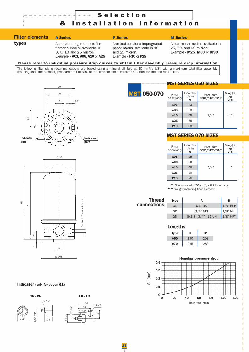
Please refer to individual pressure drop curves to obtain filter assembly pressure drop information
The following filter sizing recommendations are based using a mineral oil fluid at 30 mm2/s (cSt) with a maximum total filter assembly (housing and filter element) pressure drop of 30% of the filter condition indicator (0.4 bar) for line and return filter.
13
MST SERIES 050 SIZES
Thread connections
MST 050-070
Type
G1
G2
G3
A
3/4” BSP
3/4” NPT
SAE 8 - 3/4” - 16 UN
B
1/8” BSP
1/8” NPT
1/8” NPT
** Flow rates with 30 mm2/s fluid viscosity** Weight including filter element
Filterassembly
Flow ratel/min*
Port sizeBSP/NPT/SAE
Weightkg**
A03
A06
A10
A25
P10
42
50
65
75
68
3/4” 1,2
MST SERIES 070 SIZES
Filterassembly
Flow ratel/min*
Port sizeBSP/NPT/SAE
Weightkg**
A03
A06
A10
A25
P10
55
60
68
80
76
3/4” 1,5
Type
050
070
H
190
265
H1
208
283
Lengths
∆p (
bar)
Housing pressure drop
Flow rate l/min
0,4
0,3
0,2
0,1
00 20 40 60 80 100 120
Ø 96
Ø 7
Ø 108
B -
No.
2 T
hrea
ded
hole
s
A
Indicatorport
Indicatorport
90
56
70
25
9
70
A
H1
H
Indicator (only for option G1)
31
56Pg 7
ø 30
43
A/F.24
1/8”
BSP
ER - EC
34ø 40
A/F.14
1/8”
BSP
VR - VA

S e l e c t i o n& i n s t a l l a t i o n i n f o r m a t i o n
14
Please refer to individual pressure drop curves to obtain filter assembly pressure drop information
The following filter sizing recommendations are based using a mineral oil fluid at 30 mm2/s (cSt) with a maximum total filter assembly (housing and filter element) pressure drop of 30% of the filter condition indicator (0.4 bar) for line and return filter.
MST SERIES 100 SIZES
Thread connections
MST 100-150
Type
G1
G2
G3
A
1 1/2” BSP
1 1/2” NPT
SAE 20 - 1 5/8” - 12 UN
B
1/8” BSP
1/8” NPT
1/8” NPT
** Flow rates with 30 mm2/s fluid viscosity** Weight including filter element
Filterassembly
Flow ratel/min*
Port sizeBSP/NPT/SAE
Weightkg**
A03
A06
A10
A25
P10
80
90
125
185
175
1 1/2” 2,3
MST SERIES 150 SIZES
Filterassembly
Flow ratel/min*
Port sizeBSP/NPT/SAE
Weightkg**
A03
A06
A10
A25
P10
90
110
140
210
190
1 1/2” 2,4
Type
100
150
H
250
280
H1
275
305
Lengths
∆p (
bar)
Housing pressure drop
Flow rate l/min
0,4
0,3
0,2
0,1
00 50 100 150 200 250 300
Ø 9
Ø 129
Ø 133
B -
No.
2 T
hrea
ded
hole
s
A
Indicatorport
Indicatorport
122
72
100
36
9
100
A
H1
H
Indicator (only for option G1)
34ø 40
A/F.14
1/8”
BSP
VR - VA
31
56Pg 7
ø 30
43
A/F.24
1/8”
BSP
ER - EC

• Customer requires a 100 l/min filter assembly• Mineral oil fluid: ISO VG46 (46 mm2/s (cSt) at 40°C)• 25 micron absolute filtration• return line application
Selection :
•Housing pressure drop - MPS 100/101 with 100 l/min ∆p = 0,13 bar (see curve on page 8)
•Filter element pressure drop brochure viscosity - CS 100A25 with 100 l/min ∆p = 0,09 bar (see curve on page 17)
•Filter element pressure drop working viscosity - With 46 mm2/s (cSt) ∆p1 = 0,09 x (46/30) = 0,138 bar
•Filter assembly pressure drop ∆p Total = ∆p Housing + ∆p1 Filter element = 0,13 + 0,138 = 0,268 bar* { Acceptable pressure drop value,as per our recommendations
The curves were obtained using a
mineral oil with a density of 0,86 kg/dm.
The ∆p varies proportionally to the density.
3
GeneralPressure drop versus flow rate curve information for both housing and filter elements is in accordance with ISO 3968
Filter assembly pressure drop - ∆p Total = ∆p Housing + ∆p Filter element
Housing pressure drop - The housing pressure drop is proportional to the fluid density
Filter element pressure drop - Filter element pressure drop is proportional to kinematic viscosity therefore always check thefluid operating temperature and fluid type to obtain the working viscosity according to the following formula:
P r e s s u r e d r o p i n f o r m a t i o n
Fi l ter assembly s iz ing example
B y p a s s v a l v e s p r e s s u r e d r o p
15
1kPa = 0,01 bar
Brochure viscosity 30 mm2/s (cSt)∆p1 Filter element = (working viscosity/brochure viscosity) x ∆p filter element
∆p (
bar)
Flow rate l/min
4
R SERIES
S SERIES
3
2
1
00 20 40 60 80 100 120
MPS 050÷071
∆p (
bar)
Flow rate l/min
4
R SERIES
S SERIES
3
2
1
00 25 50 75 100 125 150
MPS 100÷301
∆p (
bar)
Flow rate l/min
4
3
2
1
00 20 40 60 80 100 120
MST 050÷070
∆p (
bar)
Flow rate l/min
4
3
2
1
00 50 100 150 200 250 300
MST 100÷150
R series: Return filterS series: Suction filter

16
The curves were obtained using a mineral oil with a kinematic viscosity of 30 mm /s (cSt).The ∆p varies proportionally to the fluid kinematic viscosity.
2
F i l t e r e l e m e n t s - P / M S e r i e s
The curves were obtained using a mineral oil with a kinematic viscosity of 30 mm /s (cSt).The ∆p varies proportionally to the fluid kinematic viscosity.
2
F i l t e r e l e m e n t s - A S e r i e s
SUCTION FILTER∆p
(kP
a)
CS - CG 050 - P/M
Flow rate l/min
10
7,5
5
2,5
00 5 10 15 20 25 30
P10
P25
M60M90
∆p (
kPa)
CS - CG 070 - P/M
Flow rate l/min
10
7,5
5
2,5
00 5 10 15 20 25 30
P10
P25M60M90
∆p (
kPa)
CS - CG 100 - P/M
Flow rate l/min
10
7,5
5
2,5
00 25 50 75 100 125 150
P10
P25
M60
M90
∆p (
kPa)
CS - CG 150 - P/M
Flow rate l/min
10
7,5
5
2,5
00 25 50 75 100 125 150
P10
P25
M60
M90
∆p (
kPa)
CS - CG 050 - A
Flow rate l/min
10
7,5
5
2,5
00 5 10 15 20 25 30
A03 A06 A10
A25
∆p (
kPa)
CS - CG 070 - A
Flow rate l/min
10
7,5
5
2,5
00 5 10 15 20 25 30
A03 A06 A10
A25
∆p (
kPa)
CS - CG 100 - A
Flow rate l/min
10
7,5
5
2,5
00 10 20 30 40 50 60
A03 A06 A10
A25
∆p (
kPa)
CS - CG 150 - A
Flow rate l/min
10
7,5
5
2,5
00 10 20 30 40 50 60
A03 A06 A10
A25

RETURN FILTER
17
The curves were obtained using a mineral oil with a kinematic viscosity of 30 mm /s (cSt).The ∆p varies proportionally to the fluid kinematic viscosity.
2
F i l t e r e l e m e n t s - P / M S e r i e s
The curves were obtained using a mineral oil with a kinematic viscosity of 30 mm /s (cSt).The ∆p varies proportionally to the fluid kinematic viscosity.
2
F i l t e r e l e m e n t s - A S e r i e s
∆p (
bar)
CS - CT - CG 050 - P/M
Flow rate l/min
0,4
0,3
0,2
0,1
00 15 30 45 60 75 90
P10
P25
M60M90
∆p (
bar)
CS - CT - CG 100 - P/M
Flow rate l/min
0,4
0,3
0,2
0,1
00 50 100 150 200 250 300
P10
P25M60M90
∆p (
bar)
CS - CT - CG 150 - P/M
Flow rate l/min
0,4
0,3
0,2
0,1
00 50 100 150 200 250 300
P10
P25
M60M90
∆p (
bar)
CS - CT - CG 070 - P/M
Flow rate l/min
0,4
0,3
0,2
0,1
00 15 30 45 60 75 90
P10
P25M60M90
∆p (
bar)
CS - CT - CG 050 - A
Flow rate l/min
0,4
0,3
0,2
0,1
00 10 20 30 40 50 60 70 80 90
A03 A06
A10
A25
∆p (
bar)
CS - CT - CG 070 - A
Flow rate l/min
0,4
0,3
0,2
0,1
00 15 30 45 60 75 90
A03
A06A10
A25
∆p (
bar)
CS - CT - CG 100 - A
Flow rate l/min
0,4
0,3
0,2
0,1
00 50 100 150 200 250 300
A03 A06 A10
A25
∆p (
bar)
CS - CT - CG 150 - A
Flow rate l/min
0,4
0,3
0,2
0,1
00 50 100 150 200 250 300
A03 A06 A10
A25
18
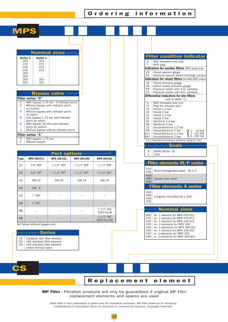
MP Filtri - Filtration products will only be guaranteed if original MP Filtrireplacement elements and spares are used
Data held in this publication is given only for indicative purposes. MP Filtri reserves to introducemodifications to described items for technical or commercial reasons. Copyright reserved.
G1
G2
G3
G4
G5
G6
F1
F2
3/4” BSP
3/4” NPT
SAE 12
SAE 8
1” BSP
1” NPT
–
–
1 1/4” BSP
1 1/4” NPT
SAE 20
–
–
–
–
–
1 1/2” BSP
1 1/2” NPT
SAE 24
–
–
–
–
–
1 1/2” BSP
1 1/2” NPT
SAE 24
–
–
–
Port optionsType MPS 050-071 MPS 100-151 MPS 200-250 MPS 300-351
S With threaded hole onlyT With plug
Indicators for suction filters (MPS series only)VS Visual vacuum gaugeEO Electrical vacuum switch exchange contactIndicators for return filters (for MPS/MST series)VA Visual pressure gaugeVR Colour coded pressure gaugeER Pressure switch with N.O. contactsEC Pressure switch with N.C. contactsDifferential Indicators for line filters
(only for series “1”)S With threaded hole onlyT2 Plug for indicator port1V Visual 1,2 barV6 Visual 2 barZ1 Visual 1,2 barZ6 Visual 2 barN1 Electrical 1,2 barN6 Electrical 2 bar1E Visual-electrical 1,2 barE6 Visual-electrical 2 bar
K1* Visual-Electrical 1,2 barK6* Visual-Electrical 2 bar
P10 Resin-impregnated paper ßx ≥ 2P25
M25M60 Square wire meshM90
A03A06 Inorganic microfibre ßx ≥ 200A10A25
O r d e r i n g i n f o r m a t i o n
MPS
CS
Nominal sizes
Filter series “0”C With bypass 1,75 bar - 4 indicator portsO Without bypass with indicator ports
on suctionP Without bypass with indicator ports
on returnR with bypass 1,75 bar and indicator
ports on returnS With bypass 30 kPa and indicator
ports on suctionU Without bypass without indicator ports
Filter series “1”R With bypass 1.75 barP Without bypass
Bypass valve
CS European std. filter elementCG USA standard filter elementCW USA standard filter element
(water removal type)
Series
A Nitrile (Buna - N)V Viton
Seals
050 no. 1 element for MPS 050-051070 no. 1 element for MPS 070-071100 no. 1 element for MPS 100-101100 no. 2 elements for MPS 200100 no. 2 elements for MPS 300-301150 no. 1 element for MPS 150-151150 nr. 2 elements for MPS 250150 nr. 2 elements for MPS 300-301
Nominal sizes
Filter elements M/P series
Filter elements A series
Filter condition indicatorSeries 0 Series 1050 051070 071100 101150 151200 –250 –300 301350 351
R e p l a c e m e n t e l e m e n t
1 1/2” SAE3000 Psi/M
1 1/2” SAE3000 Psi/UNC
G4 Option without bypass only
*For K visual-electrical indicator, specify the voltage (f.i. K61)
{ 1 - 24 Volt2 - 115 Volt3 - 230 Volt
*

MP Filtri - Filtration products will only be guaranteed if original MP Filtrireplacement elements and spares are used
Data held in this publication is given only for indicative purposes. MP Filtri reserves to introducemodifications to described items for technical or commercial reasons. Copyright reserved.
G1
G2
G3
3/4” BSP
3/4” NPT
SAE 8
1 1/2” BSP
1 1/2” NPT
SAE 20
Type MST 050-070 MST 100-150 P10 Resin-impregnated paper ßx ≥ 2P25
M25M60 Square wire meshM90
A03A06 Inorganic microfibre ßx ≥ 200A10A25
Filter elements M/P series
Filter elements A series
19
O r d e r i n g i n f o r m a t i o n
R e p l a c e m e n t e l e m e n t
MST
CT
050070100150
Nominal sizes
Seals
Port options
S With threaded hole onlyT With plug
VR Colour coded pressure gaugeER Pressure switch with N.O. contactsEC Pressure switch with N.C. contacts
Filter elements indicator
B Calibration: 1,75 bar
Bypass valve
A Nitrile (Buna - N) V Viton Seals
A Nitrile (Buna - N) V Viton

Head Quarter :MP FILTRI S.p.A. ItalyVia Matteotti, 220060 Pessano con Bornago (Milano) ItalyTel. ++39.02/95703.1Fax ++39.02/95741497-95740188email: [email protected]://www.mpfiltri.com
GREAT BRITAINMP FILTRI U.K. Ltd.Bourton Industrial ParkBourton on the WaterGloucestershire GL54 2HQ UKPhone: 01451-822522Fax: 01451-822282email: [email protected]://www.mpfiltri.co.uk
GERMANYMP FILTRI D GmbHAm Wasserturm 5D-66265 Heusweiler/HolzPhone: 06806/85022-0Fax: 06806/85022-18email: [email protected]
U.S.A.:MP FILTRI U.S.A. Inc.1256C Oakbrook Drive - Norcross,Georgia - U.S.A. 30093Phone: 770-263-0090Fax: 770-242-4069email: [email protected]
CANADA:MP FILTRI CANADA Inc.210 Jacob Keffer Parkway Concord,Ontario Canada L4K 4W3Phone: 905-303-1369Fax: 905-303-7256email: [email protected]://www.mpfiltricanada.com
®