Embed Size (px)
Citation preview

Galaxy
D1.2.1-State of the artSurvey of Academic research works and Industrial approaches to
Model Driven Collaborative Development
NAME PARTNER DATE
WRITTEN BY KEDJI E., COULETTE B., LBATH R. TRAN H.
N., EBERSOLD S., TAZI S., DRIRA K.
IRIT
ROBIN J. LIP6
KLING W. ATLANMOD
VLAEMINCK P. SOFTEAMREVIEWED BY RACARU F. AKKA
BERNARD Y. AIRBUS
©Galaxy consortium, 2010. ALL RIGHTS RESERVED. CONFIDENTIAL AND PROPRIETARY DOCUMENT.Page 1 of 87

Galaxy
State of the art
Survey of Academic research work and Industrial Approaches to Model Driven Collaborative Development
PROJECT: GALAXYREFERENCE: D1.2.1ISSUE: 1.0 Draft1
ARPEGE 2009
DATE: 06/04/2010
Record of RevisionsISSUE DATE EFFECT ON REASONS FOR REVISION
PAGE PARA
1.0 Document creation

Galaxy
State of the art
Survey of Academic research work and Industrial Approaches to Model Driven Collaborative Development
PROJECT: GALAXYREFERENCE: D1.2.1ISSUE: 1.0 Draft1
ARPEGE 2009
DATE: 06/04/2010
Table of contents
1. Introduction...........................................................................................................6
1.1 GOAL OF THIS DOCUMENT.............................................................................................6
1.2 DOCUMENT ORGANIZATION..........................................................................................6
1.3 MODEL DRIVEN ENGINEERING......................................................................................6
1.4 COLLABORATION.............................................................................................................8
1.5 COMPLEX SYSTEMS........................................................................................................9
1.6 MAIN CONCERNS IN THE GALAXY PROJECT..............................................................9
2. COMPLEX SYSTEMS .........................................................................................10
2.1 COMPLEXITY DIMENSIONS...........................................................................................10
2.2 SIZE OF MODELING ARTIFACTS..................................................................................11
2.3 HETEROGENEITY...........................................................................................................12
3. EXISTING WORKS AND TOOLS ON COLLABORATION..................................13
3.1 COLLABORATION AND COORDINATION STRATEGIES............................................13
3.1.1 Common problems ........................................................................................................13
3.1.2 Collaboration strategies.................................................................................................13
3.1.3 Coordination strategies..................................................................................................15
3.2 PROCESS MODELING AND ENACTMENT....................................................................18
3.2.1 Introduction....................................................................................................................18
3.2.2 Software Processes.......................................................................................................19
3.2.3 Notable Software Processes..........................................................................................24
3.2.4 Standard Process Modeling Formalisms.......................................................................28
3.2.5 Model-driven Development Processes..........................................................................32
3.2.6 Collaborative processes.................................................................................................33
3.3 COLLABORATION SUPPORT STRATEGIES................................................................35
3.3.1 Notification Management...............................................................................................36

Galaxy
State of the art
Survey of Academic research work and Industrial Approaches to Model Driven Collaborative Development
PROJECT: GALAXYREFERENCE: D1.2.1ISSUE: 1.0 Draft1
ARPEGE 2009
DATE: 06/04/2010
3.3.2 Update Management.....................................................................................................36
3.3.3 Merging..........................................................................................................................37
3.3.4 Annotations....................................................................................................................38
3.4 COMPUTER SUPPORTED COLLABORATION TOOLS................................................44
3.4.1 Web-based collaborative tools: Groupware, Wiki, CMS. ..............................................45
3.4.2 Online Collaborative Applications (Documents, Calendars, Conferencing etc.)............46
3.4.3 Collaborative IDEs (Jazz, etc.).....................................................................................47
3.4.4 Version Control..............................................................................................................51
3.4.5 Modelio (tool).................................................................................................................63
4. COMPARATIVE ANALYSIS AND ASSESSMENT..............................................67
4.1 COMPARISON CRITERIA...............................................................................................67
4.1.1 Version control...............................................................................................................67
4.1.2 Consistency management.............................................................................................68
4.1.3 Awareness support........................................................................................................69
4.1.4 Process support.............................................................................................................69
4.2 COMPARISON TABLES..................................................................................................70
4.2.1 Version control...............................................................................................................70
4.2.2 Consistency management.............................................................................................70
4.2.3 Awareness support........................................................................................................71
4.2.4 Process support.............................................................................................................71
5. CONCLUSION......................................................................................................72
6. BIBLIOGRAPHY..................................................................................................72
Galaxy
State of the art
Survey of Academic research work and Industrial Approaches to Model Driven Collaborative Development
PROJECT: GALAXYREFERENCE: D1.2.1ISSUE: 1.0 Draft1
ARPEGE 2009
DATE: 06/04/2010
Table of APPLICABLE DOCUMENTSN° TITLE REFERENCE ISSUE DATE SOURCE
SIGLUM NAME
A1
A2
A3
A4
Table of ReferenceD DOCUMENTSN° TITLE REFERENCE ISSUE
R1 Galaxy glossary
R2
R3
R4
ACRONYMS AND DEFINITIONS
Except if explicitly stated otherwise the definition of all terms and acronyms provided in [R1] is
applicable in this document. If any, additional and/or specific definitions applicable only in this
document are listed in the two tables below.
Acronyms
ACRONYM DESCRIPTION
Definitions
TERMS DESCRIPTION

Galaxy
State of the art
Survey of Academic research work and Industrial Approaches to Model Driven Collaborative Development
PROJECT: GALAXYREFERENCE: D1.2.1ISSUE: 1.0 Draft1
ARPEGE 2009
DATE: 06/04/2010
Galaxy
State of the art
Survey of Academic research work and Industrial Approaches to Model Driven Collaborative Development
PROJECT: GALAXYREFERENCE: D1.2.1ISSUE: 1.0 Draft1
ARPEGE 2009
DATE: 06/04/2010
1. INTRODUCTION
1.1 GOAL OF THIS DOCUMENT
The present document is a survey and assessment of the various academic and industrial works relevant to the
Galaxy Project (“Model Driven Collaborative Development of Complex Systems”). This document constitutes the
project’s state-of-the-art (WorkPackage 1, Task 2).
The study, on the one hand, evaluates CASE Tools which support collaboration and/or MDE and surveys the
capabilities of their technologies, and on the other hand, reviews academic works on: viewpoint-and-view based
MDE, transformation handling, development environments, and process modeling and enactment, in the
context of collaborative development teams a n d complex systems.
A particular attention is paid to the surveys done by the Movida [Consortium, 2008] (“Model Driven View- point
Engineering”), Lambda [Lambda, 2009] (Model Driven Development of Complex Industrial Systems), and
TOPCASED [Farail et al., 2006] (Model Driven Development of Critical Embedded Systems) project. These
surveys will be reevaluated in the context of the Galaxy Project, so as to highlight the issues raised by the
number and size of models and teams.
1.2 DOCUMENT ORGANIZATION
The current chapter, the introduction, delineates the document objectives, explains the main concepts, and
restates the main issues of the project. Chapter 2 discusses complex systems, and chapter 3 explores collaboration
and coordination strategies, techniques, and tools. Finally, chapter 4 compares the different propositions and
concludes.
1.3 MODEL DRIVEN ENGINEERING
Model Driven Engineering is usually described as an Engineering approach that promotes the use of models and
transformations as primary artifacts throughout the product development. A detailed exploration of the principles
behind MDE is out of scope for this document. However, a brief summary of the philosophy behind MDE is
necessary for an accurate evaluation of the impacts of collaboration and complexity. This can be done by drawing
a parallel between MDE and the familiar c o d e compiler revolution [Kurtev et al., 2002], which is rightly
viewed as a radical shift in the way software is built.
In software engineering, using better abstractions is all about capturing whatever concepts already exist, in some
ad-hoc way, in existing code. The computer revolution brought clear and formal ways to iterate, chose
alternatives, create functional units and use them, etc. Similarly, MDE promises a new class of abstraction
facilities [Weigert & Weil, 2006], directly related to domain under study [Booch et al., 2004].
Galaxy
State of the art
Survey of Academic research work and Industrial Approaches to Model Driven Collaborative Development
PROJECT: GALAXYREFERENCE: D1.2.1ISSUE: 1.0 Draft1
ARPEGE 2009
DATE: 06/04/2010
Whenever the abstraction level is raised, some of the details necessary for full code-generation are lost. To retain full
code-generation capability, it is necessary to introduce domain specific concepts (supported by their implementations in
transformation tools). MDE is thus usually domain-focused (UML Profiles, DSLs, etc.) in contrast with general
purpose languages (GPL). Dealing with domain-specific concepts requires tight collaboration between the
underlying platform, the tool, the metamodel, and the modeling language [Tolvanen, 2004].
Compilers considerably reduced the work required for making t h e code work for different target machines
(with different instruction sets). This trend is also visible with the advent of virtual machines (targeting different
operating systems) and recently, X-to-Javascript compilers (targeting different browsers). In the case of models,
we may want to target different technology stacks (.NET, J2EE, etc.) as in OGM’s MDA [Kleppe et al., 2003], or
different special-purpose hardware architectures (GPU, FPGA, Cell parallel processor, etc.) [Stewart, 2009] [Anand
& Kahl, 2007].
Having an appropriate way to package information is necessary for effective reuse. The first compilers
introduced artifacts like functions, which made it easy to reuse a piece of code. Later, modules, packages, aspects,
etc. have been used to the same end. However, a unit of functionality related to a domain concept, is much more
likely to be useful in a later project [Occello et al., 2007]. This is because domain knowledge changes slower than
technical tactics. MDE, by capturing the semantics of domain-concepts into models, takes reuse to new levels
[Estublier et al., 2005] [Ionita et al., 2007].
When software is used in mission and time-critical applications, reliability is a major concern. Compilers helped a
lot by moving a lot of tedious and error-prone tasks (like memory allocation) into reliable compiler code. Today,
MDE not only moves a lot of tedious work into transformation tools, but also allows a wide range of
automated verification and simulation, raising the standard for reliability [Selic, 2003] [Rodrigues et al.,
2004].
Finally, the compiler revolution not only brought better abstractions, it also redefined what programming is, by
creating various programming paradigms. The software engineer can think of his programs as a list of orders
(imperative programming), definitions made with mostly stateless functions (functional programming), a search
problem (logic programming), etc. In MDE, the task of the developer is to capture the concepts and relations
the system to be built is made of. The main idea here is to construct various models of a system, each of them
capturing an aspect of the system, and allowing us to reason about the system. A model is therefore, first, an
intellectual tool used to tame complexity, to improve our understanding of a problem and its solution [Stewart,
2009] [Rodrigues et al., 2004].
In The Pragmatics of Model Driven Development [Selic, 2003], Bran Selic describes a good model as abstract,
understandable, accurate, predictive, and inexpensive. The selling point is that MDE allows a higher degree of
automation.
Galaxy
State of the art
Survey of Academic research work and Industrial Approaches to Model Driven Collaborative Development
PROJECT: GALAXYREFERENCE: D1.2.1ISSUE: 1.0 Draft1
ARPEGE 2009
DATE: 06/04/2010
Seidewitz investigates the meaning of models in What Models Mean [Seidewitz, 2003]. Software modeling is
similar to the activity physicists engage in when trying to understand and predict how the universe works. The
goal is to write down the rules a system obeys to, and deduce properties it has, using the paradigms and concepts
our modeling language embodies (just like Newton’s laws allow us to predict things about falling apples).
In his landmark paper on Model Driven Engineering [Kent, 2002], Stuart Kent considers MDE as a set of
activities producing various models, each describing a particular aspect of the system to be implemented. He
suggests the organization of these models (the modeling space) along various orthogonal dimensions (like the
PIM-PSM continuum), and an explicit description of how and when these models are produced (process).
Models have also been used to unify the software world, as much as objects have been used in object-oriented
technology [Bézivin, 2005]. Two fundamental relations are defined for models: a representation relation (with
respect to the system considered) and a conformity relation (with respect to its metamodel). Every artifact the
developer has to deal with is then considered a model, thus promoting the concept of model to the rank of a
unifying idea.
1.4 COLLABORATION
Computer-supported collaboration is the use of computers to enhance the ability of humans to collaborate.
Collaboration is, simply put, the act of working jointly with others [Galaxy, 2009]. It has been defined as a
coordinated, synchronous activity that is the result of a continued attempt to construct and maintain a shared
conception of a problem [Roschelle & Teasley, 1994] [Van den Bossche et al., 2010].
Collaboration can be seen as a technique to allow a group of individuals to be more effective than the sum of
their individual effectiveness, in which case the concept of collective intelligence [Weiss, 2005] is used. However,
usually (and in the context of the Galaxy Project), collaboration is all about solving the problems that arise when
working in groups, the situation being imposed by the size of the project [Whitehead, 2007]. Galaxy ignores, on
purpose, the social and human aspects of collaboration, and concentrates on tooling.
The terms collaboration and cooperation are often used interchangeably in informal discussions. However, some
differences are usually highlighted in the literature between these concepts. Cooperative work is accomplished by
a division of labor between participants, an activity where each person is responsible for a portion of the problem
solving, while collaboration is the mutual engagement of participants in a coordinated effort to solve a problem
together [Roschelle & Teasley, 1994]. In cooperation, partners split the work, solve sub-tasks individually and
then assemble the partial results into the final output. In collaboration, partners do the work “together”.
However, some spontaneous division may occur even when two people do really work together, for instance one
partner taking responsibility for the low levels aspects of the task while the other focuses on strategic aspects
[Dillenbourg, 1999]. As purely cooperative situations can arise in collaborative work, Galaxy exclusively uses the term
“collaboration” for collective efforts.

Galaxy
State of the art
Survey of Academic research work and Industrial Approaches to Model Driven Collaborative Development
PROJECT: GALAXYREFERENCE: D1.2.1ISSUE: 1.0 Draft1
ARPEGE 2009
DATE: 06/04/2010
In collaborative and cooperative situations, coordination refers to the act of making different people or things
work together for a goal or effect [Wikipedia, n.d.]. It is the regulation of diverse elements into an integrated
and harmonious operation [Wordnet, n.d.]. As such, it usually involves some managerial role, distinct of those
of the participants doing the real work.
1.5 COMPLEX SYSTEMS
Complex systems have been defined as systems that resist to reductionist approaches, that is, understanding
their various parts does not suffice to grasp the behavior of the whole [Lambda, 2009]. Intuitively, a complex
system is thus more than the sum of its parts, partly because of some additional properties arising only because of
the interactions between the parts (sometimes called emergent properties [Standish, 2001]).
It should be noted that MDE itself is used to tame the complexity of systems. The Galaxy Project explores the
additional complexity arising from collaboration of large-scale projects. This complexity can be traced back to
some key issues, which are discussed in the next section.
1.6 MAIN CONCERNS IN THE GALAXY PROJECT
The central preoccupation in the Galaxy Project is how to make Model Driven Development work when collaborating
on complex systems. Practically, the resulting issues that need to be addressed are [Galaxy, 2009]:
• The size and number of models;
• The size of development teams;
• The heterogeneity of development environments.
A lot of factors contribute to the steady increase in the size of models. Besides the obvious influence of the size of
the system under study, there is the increasing complexity of those systems (whether by virtue of internal relations or
interactions with external systems), the mostly graphical representation of models which use much more storage than
traditional code or textual specifications, etc. Additionally the pervasiveness of models, from requirements to tests, and
the multiplicity of models needed to represent the various views of systems, lead to an ever increasing number of
models. These gigantic structures are rarely directly manageable by the facilities offered by the existing tools (version
control systems, build systems, continuous integration tools, etc.).
Large-scale industrial development projects are usually handled by large and geographically distributed teams.
Organizations have to cope with an increasing need for coordination. However, models introduce additional issues,
rarely addressed by existing facilities. On the one hand, the relationships between model artifacts are much more

Galaxy
State of the art
Survey of Academic research work and Industrial Approaches to Model Driven Collaborative Development
PROJECT: GALAXYREFERENCE: D1.2.1ISSUE: 1.0 Draft1
ARPEGE 2009
DATE: 06/04/2010
diverse and numerous. On the other hand, it is not obvious how to split large models into meaningful units, so that
different people can work on them, nor is it easy to maintain consistency and merge contributions in such situations.
One of the stated goals of Galaxy is to support heterogeneous environments. Therefore, no assumption is made about,
neither the tools used by the different teams, nor the environments they are running in. Thus, unlike collaborative tools
which assume a homogeneous environment, Galaxy needs to define a reference framework to make collaboration
possible in a diversified environment. Finally, the complexity resulting from the possible changes, either in the tools
used, or in team composition, and possible impacts on model management, have to be addressed.
The interaction of the size and number of models, the size of the development teams, and the heterogeneity of
environments creates great pressure on the development process. Coordination problems arise inevitably, as more and
more people try to collaborate on bigger and more numerous models, using more and more diverse tools.
2. COMPLEX SYSTEMS
One of the most recent works with large modeling artifacts is the Lambda project. Lambda project aimed to identify the
possible bottlenecks in the scaling up of MDE techniques. Its main focus was the building and management of large
libraries of modeling artifacts. Lambda project made several experiments with concrete industrial uses and have
partially addressed the wide problem of the scalability of MDE.
As said before, collaborative development of MDE complex systems usually involves large sized models, large
numbers of models, and artifacts and tools heterogeneity. The followings are the conclusions achieved by lambda
project regarding to the collaborative development of complex systems.
2.1 COMPLEXITY DIMENSIONS
There were identified four dimensions of complexity for the main modeling artifacts as show in the table below.
The size, quantified for the models in terms of the number of model elements and for the transformations in
term the number of rules they contain.
Evolutivity, quantified in terms of the periodicity with which a modeling artifact is being updated.
Heterogeneity, quantified in terms of the different technical spaces and formats an artifact may be found and
finally the quantity or amount of artifacts.
Note that depending on the artifact, the complexity dimension may be more critical, e.g., a change in a metamodel
usually has more impact than a change in a model. Lambda project addressed specially the Size dimension.
Galaxy
State of the art
Survey of Academic research work and Industrial Approaches to Model Driven Collaborative Development
PROJECT: GALAXYREFERENCE: D1.2.1ISSUE: 1.0 Draft1
ARPEGE 2009
DATE: 06/04/2010
2.2 SIZE OF MODELING ARTIFACTS
The scalability of MDE tools when working with large models was assessed in terms of the behavior of the most
common modeling operations. These operations are reading, saving and transforming models.
Saving models: Most of the modeling frameworks store models in XMI format. Storing models in this
format requires much more space than other formats. Lambda project proposed a compact binary format to
store models called Binary Model Storage (BMS). This format reduces significantly the required storage
space and also offers complete random access to model elements which is useful for reading the operations
to be able to access only the desired element.
Reading models: Reading and then storing large models in memory is an expensive operation because
most tools load the whole models in memory. This operation not only needs many resources, but takes
significant amounts of time to be performed. Most of the time not all the elements of the models are
required. Thus, it was concluded, that lazy loading of models is a good solution for addressing the
scalability problems when working with large models. It reduces the memory footprint and the time spent
for opening and reviewing the model. The lazy loading of models was possible thanks to the BMS.
Transforming models: When transforming large models, in some border cases, the 95% of total time
spent by the transformation is spent in loading and saving the models. This is the case when the

Galaxy
State of the art
Survey of Academic research work and Industrial Approaches to Model Driven Collaborative Development
PROJECT: GALAXYREFERENCE: D1.2.1ISSUE: 1.0 Draft1
ARPEGE 2009
DATE: 06/04/2010
transformation is small and simple and the models are too large. With models lazy loading, the time spent
by these transformations reduced significantly despite the transformations performed about 40% slower.
Another important aspect around large models was their projection to other technical spaces. Projection is the
cornerstone of model discovery, which consists in creating models from sources in any technical space and then
performing operations like management, analysis, transformations, etc. on them. Injecting models is a complex process
because is difficult to prove the completeness of the metamodel and the injection solution, used to produce them. It is
also very difficult to achieve a good performance with custom made solutions when injecting large models. It was then
concluded, that newly produced injectors should rely on forward engineering existing tools, like parsers of code
compilers. This is the approach used actually by [Modisco 2010] for injecting java code.
2.3 HETEROGENEITY
Another bottleneck identified for MDE scalability is the MDE artifacts heterogeneity. The key points of heterogeneity
are:
Sources: MDE artifacts come from different sources like models, databases, source code, configuration
files etc.
Data formats: Due to the different artifact sources and the different tools, information appears in the
form of many different file formats e.g., XMI files and textual syntaxes.
Process: Depending on the process, models containing complementary information may exist at
different level of abstraction or metamodels which capture the same ideas may be different.

Galaxy
State of the art
Survey of Academic research work and Industrial Approaches to Model Driven Collaborative Development
PROJECT: GALAXYREFERENCE: D1.2.1ISSUE: 1.0 Draft1
ARPEGE 2009
DATE: 06/04/2010
Based on previous works, it is advised to use a unified representation of modeling artifacts like a megamodel [Bézivin,
et Valduriez] and to use projectors (injectors and extractors) for aligning different technical spaces. The megamodel
may also be used to orchestrate the derivation process between models.
3. EXISTING WORKS AND TOOLS ON COLLABORATION
3.1 COLLABORATION AND COORDINATION STRATEGIES
This section explores various problems that arise in collaborative settings, and existing approaches to resolve them and
enhance the effectiveness of collective work.
3.1.1 Common problems
Cramton has investigated the common p r o b l e m s a geographically dispersed team faces when
collaborating on a project. "Maintaining mutual knowledge” turns out to be the central issue. The other issues
were, namely, failure to communicate and retain contextual information, unevenly distributed information,
differences in the salience of information, relative differences in the speed of access to information, and
interpreting the meaning of silence [Cramton, 2001].
In [Herbsleb, 2007], Herbsleb explores the coordination challenges that arise in geographically dispersed
teams. He explains how ineffective communication, lack of awareness, and incompatibilities can make
coordination difficult. A particular emphasis is placed on how to achieve organizational and architectural fit,
an idea that can be traced back to Conway’s law: “organizations which design systems ... are constrained to
produce designs which are copies of the communication structures of these organizations” [Conway, 1968].
3.1.2 Collaboration strategies
Collaboration can have different senses, among which [Goldberg, 2002]:
Conceptual collaboration
Practical collaboration
Educational collaboration
Conceptual collaboration (sharing responsibility, information and leadership) and practical collaboration
(decomposition of work, integration of work results, and management of differences in expertise) are the most
relevant to the Galaxy project. While educational collaboration (helping one another learn the job) is important for
businesses, it is only remotely related with the objectives of the Galaxy project.
Regardless of the sense given to collaboration, projects which are overall collaborative exhibit four main types of
work [Robillard & Robillard, 2000]:

Galaxy
State of the art
Survey of Academic research work and Industrial Approaches to Model Driven Collaborative Development
PROJECT: GALAXYREFERENCE: D1.2.1ISSUE: 1.0 Draft1
ARPEGE 2009
DATE: 06/04/2010
Mandatory collaborative work
Called collaborative work
Ad-hoc collaborative work
Individual work
Mandatory collaborative work (regular meetings planned before the project starts) and called collaborative work
(reviews and meetings planned in the course of the project) are of mild interest to Galaxy, when they are carried
out with tools not used for actual development. Ad-hoc collaborative work (short and mostly one-to-one
discussions which usually precede or follow long individual work sessions, and serve to decompose or assemble
work) and individual work are more relevant to Galaxy. It should be noted that ad-hoc collaboration is the most
common type of collaborative work [Perry et al., 1994, Robillard & Robillard, 2000].
In its broadest sense, collaborative work normally involves a facilitator -- the one in charge of the coordination
role. Briggs et al. have identified some ready-made techniques a group can use to create some predictable
collaborative process patterns, without the intervention of a facilitator. These techniques are called thinkLets, and
can serve as building blocks for collaborative process design [Kolfschoten et al., 2004]. The thinkLet concept is a
fundamental one in the field of collaborative engineering. Each thinkLet can produce some well-defined and
predictable variation of one of the main collaboration patterns [Briggs et al., 2006]:
Generate: Move from having fewer to having more concepts in the pool of concepts shared by the
group
Reduce: Move from having many concepts to a focus on fewer concepts that the group deems
worthy of further attention
Clarify: Move from having less to having more shared understanding of concepts and of the words
and phrases used to express them.
Organize: Move from less to more understanding of the relationships among concepts the group is
considering
Evaluate: Move from less to more understanding of the relative value of the concepts under
consideration
Build consensus: Move from having fewer to having more group members who are willing to
commit to a proposal.
A simple classification of day to day collaborative activities can be made with respect to time and place. This
scheme distributes activities in four conceptual quadrants [Cook, 2007]:
Co-located and synchronous (ex: face-to-face meetings)
Co-located and asynchronous (ex: office document editing)
Distributed and synchronous (ex: chat)

Galaxy
State of the art
Survey of Academic research work and Industrial Approaches to Model Driven Collaborative Development
PROJECT: GALAXYREFERENCE: D1.2.1ISSUE: 1.0 Draft1
ARPEGE 2009
DATE: 06/04/2010
Distributed and asynchronous (ex: email)
3.1.3 Coordination strategies
Computer-supported collaborative work tools are becoming very popular since the last decade. Among these tools, we
can name teleconference, multimedia fax and mail or collaborative editing tools [Georganas, 1997]. In the last category,
shared editors are a large software family. They allow the treatment of several document types: multimedia, graphic or
textual, plain or formatted text.
Computer-supported cooperative software for editing offers several advantages: the most obvious one is of course the
possibility for different users to simultaneously work on the same document while being located in different places.
Using such an editor, users can work on a document as a distributed group, without the constraint of being in the same
place at the same time.
[Olson et al., 1993] shows a study aiming at proving the utility of computer-supported editing software for group work.
38 work groups were given an exercise. Half of the groups had to work with ‘‘classical’’ supports (paper, blackboard)
and the other half had to use a shared editor called ShrEdit. This experience showed that the work of the groups that
were using the classical supports is of a lower quality. In fact, in computer supported groups, everybody simultaneously
work on the final document. Users are not constrained to write the document at the end of the session. So it is easier to
modify the document, and to avoid loss of ideas or deformation between discussion phases and writing phases.
Conflict handling (i.e. dealing with two simultaneous modifications of the same part of the document) is one of the most
important features of a shared editor. Related paper works on the subject enlighten two approaches of this problem
[Koch, 1995].
In a ‘‘light’’ conflict handling, several users are allowed to work on the same resource at the same time. Their
modifications are filled using a versioning tool, then they enter a negotiation phase, in which they discuss the version to
keep and what changes should be made.
A ‘‘heavy’’ conflict handling aims at solving the problem upstream, by avoiding simultaneous modifications of a single
resource. A coordination protocol prevents users from working on the same part of the document at the same time.
[Dommel and Garcia-Luna Aceves, 1998] names two coordination protocol families: implicit and explicit coordination
protocols.
In an implicit protocol, you know what a resource state is by asking local parameters using the network. The problem
here is to show a consistent resource view. Moreover, the need of permanent message exchange results in a low
functionality protocol rate. In addition, those protocols are more likely to cause collisions (the lock of the same resource
by more than one user) because of the network response time.

Galaxy
State of the art
Survey of Academic research work and Industrial Approaches to Model Driven Collaborative Development
PROJECT: GALAXYREFERENCE: D1.2.1ISSUE: 1.0 Draft1
ARPEGE 2009
DATE: 06/04/2010
Explicit protocols use a resource marking protocol. For example, a token may be used to show the state of a resource.
This token may be asked for, refused, given away or released. Information concerning the resource state will not be
local anymore, so collision risks are greatly reduced.
[Dommel and Garcia-Luna-Aceves, 1998] then distinguish branching in this taxonomy: implicit coordination can be
divided into three groups:
Coordination (users are unaware of other sites’ activities),
Social Mediation (users negotiate who can modify the resources at a given time)
Activity Sensing (local agents monitor activities on resources).
In the same way, explicit coordination protocols can be divided into three classes:
Fully Connected (when a user wants a token, he has to ask all the sites),
Ring-Based (a token rotates in a previously defined sequence among sites; it stops in a site that asked for that
specific resource, and passes over otherwise) or
Tree-Based; a subcategory of the last class is a star-like structure, in which the token comes back to the center
when released. Every user can then ask in order to obtain it.
Requirements for cooperative editing
Considering existing studies, e.g. [McAlpine and Golder, 1994] [Koch, 1995], we can summarize the features a
computer-supported cooperative editing tool should provide:
Text processing: The tool should include all text processing basic options, such as choice of fonts,
formatting and copy/paste.
Standard file formats: Many existing shared editors use ad hoc file formats. These formats are created for a
single software, for which they are totally adapted, and are incompatible with other text processing tools.
The use a standard format would allow users to work on the document off-line, with another software.
Conflicts handling: Conflicts control is an essential feature of computer-supported cooperative work
software. The ways of dealing with a conflict will be discussed later.
Consistency: Users must have the same vision of the state of the document (contents and resources lock) at
a given time.
Easy to use: The tool must be simple to use, with a look-and-feel that can satisfy every user. Moreover,
users should not have to deal with constraints such as document presentation: such decisions can be taken
later on.
Reusability: Users should be allowed to reuse parts of their former documents, so they would not have to
do the same work twice.
Versioning: the tool should permit to keep several versions of a single document, so that a user can take
back older versions of the document he is currently working on. Most articles on the subject mention
another important feature: communication between users. All proposed working modes have two common
features:

Galaxy
State of the art
Survey of Academic research work and Industrial Approaches to Model Driven Collaborative Development
PROJECT: GALAXYREFERENCE: D1.2.1ISSUE: 1.0 Draft1
ARPEGE 2009
DATE: 06/04/2010
Every user should be informed of his co-workers’ actions. We can list two different information types:
synchronous (knowing who is working on what, being aware of modifications as soon as they are made)
and asynchronous (what has been changed since the last work session). Asynchronous information is very
useful when using a versioning tool: it allows users to compare different versions of a document and
possibly come back to an older version. [Koch, 1995].
Moreover, the tool should provide a communication support, in order to allow users to make decisions,
discuss changes to the document and solve conflicts. Many communication supports implement a user role
system. Writers, readers (who give their opinion about the writers’ work), mediators (who arbitrate
conflicts between users) are examples of suggested roles. [McAlpine and Golder, 1994] [Koch, 1995].
Cooperative editing approaches
We can list several approaches in shared work modes [Santos, 1995]: users can work in asynchronous mode (each user
works separately and uploads his work when it is finished) or synchronous mode (all users use the tool simultaneously).
A computer-supported collaborative editing tool should allow users to work using both modes. What You See Is What I
See (WYSIWIS) is a standard concept when working in synchronous mode, and its usefulness has already been proved
[Olson et al., 1990]. The most obvious implementation of this system is ‘‘strict’’-WYSIWIS, in which all users have the
same view on the document. Nevertheless, this method induces two major disadvantages, one technical and the other
psychological: When a user works on a document part, the view of all the others must be permanently refreshed. This
induces a constant message flow on the network that can reduce the tool’s performances. A user often works better
when he has his privacy than when he knows that all users can constantly read what he is writing. A relaxed-WYSIWIS
mode lets writers decide at what moment their work should be shown to the rest of the group.
Various shared editors have been developed, and we will just mention a few. In [Koch, 1995], we can find a description
of Iris, a shared editing environment. It handles hierarchic tree structures and stresses on granularity (i.e. possibility for
users to define their own document partition system). Iris permits processing various document types, such as text,
videos, images... Its architecture relies upon a two levels model: a user-interface level, and an access level (which
handles data access authorizations.).
SIFT is an editor who relies upon a client/server architecture. It permits to manage the WYSIWIS (heavy and light) and
handles conflicts thanks to a reservation system whose granularity can be parameterized. The state of the document is
stored locally on each author’s workstation. These copies are transmitted to a central server which thus ensures
consistency [Baecker et al., 1992]. [Ellis et al., 1991] presents Grove, a synchronous editor intended for the creation of
hierarchically organized documents, and built to be used like a tool of remote editing or like a support of meeting. It
offers an audio communication system to allow an informal management of coordination. Quilt [Fish et al., 1988] is a
shared editing tool which was based on many studies on shared work. It rather stresses the collaboration aspect of the
divided editing, with functionalities making it possible to communicate, annotate, inform and revise. Moreover, it
permits to allot roles to the users and proposes several types of cooperation (exclusive access, shared, editor). These
four editors are representative of a ‘‘user’’ approach of shared editing, where one tackles the subject from the point of
view of the people wishing to use the software.
Galaxy
State of the art
Survey of Academic research work and Industrial Approaches to Model Driven Collaborative Development
PROJECT: GALAXYREFERENCE: D1.2.1ISSUE: 1.0 Draft1
ARPEGE 2009
DATE: 06/04/2010
The editors introduced hereafter show another approach, focusing on the structure of the application. [Bendix et al.,
1998] presents CoEd, a tool dedicated to versioning textual documents shared editing. This application is built upon a
three-layer architecture: the ‘‘GUI’’ layer implements the user interface, the ‘‘design’’ layer includes all advanced
features aiming at relieving users of parts of their work, and the ‘‘engine’’ layer implements versioning functions. This
model however, differs from CCC (which stands for ‘‘Communication and Coordination support for group
Cooperation’’) because of the correlation between cooperation and coordination functions: in CoEd, these functions are
integrated in the same layer (engine). CoEd generates laTeX documents.
Another approach of shared editing is enlightened by McAlpine and Golder (1994) where CollaboWriter, the tool
presented, relies upon a ‘‘light’’ coordination protocol. Users are not prevented from working on the same part of the
document. When this happens, a versioning tool keeps track of both versions. A negotiation protocol, assisted by a
human mediator then allows the concerned users to take decisions about the version to be kept. In a third phase, readers
annotate the document and propose modifications. The interest of this solution relies on the fact that it focuses on
collaborative editing constraints rather than technical constraints.
3.2 PROCESS MODELING AND ENACTMENT
3.2.1 Introduction
An engineering process means the set of activities required to produce a product, executed by a group of people that are
organized according to a given organizational structure. When several developers work collaboratively on a common
project, organizations need some way to coordinate their work. For relatively small or simple tasks, this can often be
done informally, but with larger numbers of developers and complex systems, more formal arrangements are needed.
Furthermore, for complex systems, the development process is a critical factor because experience has shown in many
industrial fields that processes have a profound influence on products. By controlling processes, we can achieve a better
control of the required qualities of products. Modeling the process appears then as a necessity in order to better
understand it, to assess its performance, and to enhance its quality and, thus, to enhance quality of products.
If no explicit process is in place, the development can be considered as a black pipe with product requirements at the
input side and, hopefully, the desired product delivered at the output side. Unfortunately, in many practical cases, when
the product appears at the output side of the pipe, months or years since the development started, it can become very
expensive to ensure the quality of the product or even its correctness. Therefore quality concerns and correctness should
be considered overall the whole process and cannot be delayed to the end of the process.
Modeling of software development processes refers to the definition of the processes as models, plus any optional
automated support available for modeling and enacting the models during software development. Curtis et al [Curtis,

Galaxy
State of the art
Survey of Academic research work and Industrial Approaches to Model Driven Collaborative Development
PROJECT: GALAXYREFERENCE: D1.2.1ISSUE: 1.0 Draft1
ARPEGE 2009
DATE: 06/04/2010
1992] present some of the specific goals and benefits of modeling and enactment of the software development process:
ease of understanding and communication, process management support and control, provision for automated
orientations for process performance, provision for automated execution support, process improvement support.
A business process means the set of activities required to provide a product or a service to an organization’s customer.
Though, like a business process, a engineering process aims to deliver a (industrial) product to a customer, it is radically
different in nature. While business processes refer to very stable business procedures (e.g. processing an online
customer order) with a clear flow of data and activities to be carried out to satisfy a customer’s demand, engineering
processes refer rather to engineering and highly creative activities involved in creating an industrial product, that cannot
be described in details in terms of stable business procedures. However, at the macro-level and only at that very high
level of abstraction, engineering processes follow a precise and stable lifecycle that could be assimilated to a business
process.
While the general focus of section 3.2 is on engineering process modeling, that is, systems processes as well as software
processes, the surveyed works relate mostly to software processes. In fact, we are aware of little to none works of
process models with a special focus on systems engineering. Thus, unless explicitly stated, ‘process’ or ‘engineering
process’ in the following subsections refers to ‘software engineering process’.
The rest of this section aims to give a brief survey on works dealing with process modeling and assisted enactment.
Section 3.2.2 presents the main works on software process modeling and enactment. Section 3.2.3 gives a brief
description of standard-like processes in the domain of software engineering. Section 3.2.4 presents the standard
process modeling formalisms. Section 3.2.5 gives a survey on model-driven development processes. Section 3.2.6 deals
with collaborative development processes.
3.2.2 Software Processes
The focus on software processes can be traced back to the early stages of the field of Software Engineering. The
attention dedicated to the field up to now has lead to many approaches. In this section, we present the most
representative approaches that were followed by the pioneer works dealing with the domain.
3.2.2.1 Process-Improvement Methods
Process-improvement methods were proposed in order to apply to the software development process international
quality standards, like the ISO9000 series. The most popular Process-Improvement method is the Capability Maturity
Model Integrated (CMMI), developed by the Software Engineering Institute [Humphrey, 1989], which has lead to the
well-known SPICE Standard ISO/IEC 15504.
The CMM defines five maturity levels (namely, Initial, Repeatable, Defined, Managed, and Optimizing) that
characterize a software development organization and efforts or activities to be achieved by organizations to jump from

Galaxy
State of the art
Survey of Academic research work and Industrial Approaches to Model Driven Collaborative Development
PROJECT: GALAXYREFERENCE: D1.2.1ISSUE: 1.0 Draft1
ARPEGE 2009
DATE: 06/04/2010
one maturity level to the next one.
The Process-Improvement methods have been important because they highlighted the necessity of explicitly describing
the process and stressed the managerial aspects of software development. However, it may be observed that in some
cases they did not result in better organization, but rather in increased bureaucracy. Process-Improvement methods seem
to be mostly oriented towards large and highly structured organizations, than towards small and highly flexible
organizations.
3.2.2.2 Lifecycle-based Models
The initial solution proposed for handling the software development process is the concept of software lifecycle, which
defines the standard “life” of a product, from its initial conception until deployment and maintenance. The software
development process is decomposed into a predefined sequence of phases, each of which receives inputs from the
previous phase and provides output to the following phase.
The main proposed lifecycles are the waterfall model, the V-shaped model, and the spiral model [Royce, 1970] [Boehm,
1986]. All these models try to organize software development as a sequence of steps, assuming that all requirements are
acquired before proceeding to design, that design should be completed before one proceeds to implementation, and so
on.
The experience, however, has shown that strict versions of these models work rarely, and do not work at all in real-
world cases. Initial requirements are almost inevitably incomplete and imprecise, sometimes even wrong. Furthermore,
the lifecycle models provide a rigid decomposition into standard development activities but, in practice, software
developers found it hard to follow such fixed, and predefined process models. Inevitably, software production contains
creative design steps and it cannot be completely predefined. Thus software development requires flexible and adaptive
lifecycles.
3.2.2.3 Agile Processes
In many modern real-world contexts where software development requires reacting to highly dynamic markets and
continuous changes of technologies, the approaches proposed by the pioneer works seem to be rigorous, disciplined,
bureaucratic, and heavyweight [Derniame, 2004]. For handling highly flexible and reactive software development, agile
approaches have been introduced. Several approaches fit under the agile banner, including: Extreme Programming,
Crystals, Adaptive Software Development, and Scrum [Abrahamsson, 2002] [Boehm, 2002] [Cockburn, 2001].
Extreme Programming (XP) has evolved from the problems caused by the long development cycles of traditional
lifecycles models. It is an evolutionary iterative development process that relies on refactoring a base system for each
iteration. All the development focuses on the current iteration with no design done for anticipated future needs. The
result is a design process that combines discipline with adaptability.
Galaxy
State of the art
Survey of Academic research work and Industrial Approaches to Model Driven Collaborative Development
PROJECT: GALAXYREFERENCE: D1.2.1ISSUE: 1.0 Draft1
ARPEGE 2009
DATE: 06/04/2010
Crystals is an iterative process that puts a lot of weight in end of iteration reviews, thus encouraging the process to be
self-improving. It relies on the assertion that iterative development is there to find problems early, and then to enable
people to correct them. This places more emphasis on people monitoring their process and tuning it as they develop.
Adaptive Software Development (ASD) is a development process based on three non-linear, overlapping phases:
speculation, collaboration, and learning. ASD views traditional planning as a paradox in an adaptive and unpredictable
environment. Deviations from plans are not viewed as mistakes, but are to be used as a guide towards the correct
solution.
Scrum relies on the assumption that defined and repeatable processes only work for tackling defined and repeatable
problems with defined and repeatable contexts. Scrum divides a process into short iterations, called sprints. Before a
sprint begins, the functionality required for that sprint is defined, and then the team is left to deliver it. The point is to
stabilize the requirements during the sprint. Regularly, the team has to hold a short meeting, called scrum, where the
team runs through what it will do until the next scrum.
3.2.2.4 Process-Support Approaches and PSEE
Process-support approaches originate in Osterweil’s work [Osterweil, 1987]. Osterweil started from the observation that
organizations differ in domains of specialization, culture, and development strategies. And even within a same
organization, different projects may present huge variations. Thus, there is no unique development process. A specific
process should be defined for each set of similar problems and should take into account all particularities of the
organization and product being developed. Also, software engineering environments that support software development
should be able to be tailored to specific development processes and to specific development projects.
Works on process-support approaches focused on the elaboration of Process-centered Software Engineering
Environments (PSEE), with the aim to offer software development environments through an explicit process model in
order to provide the best possible automated support. By the means of a suitable process modeling language, a process
model specifies how people should interact and work, what kinds of artifacts they should produce, which tools they may
or should use, and what policies and standards they should conform to. A process engine can then enact (i.e., execute)
the process model, in order to guide and support people in performing the process, and automate the execution of
activities that do not require human participation.
A large number of prototypes of PSEE have been developed. They can be classified into two main families [Gruhn,
2002]: a first-generation PSEE that are characterized by their emphasis on describing processes as normative models;
and a second-generation PSEE that try to offer more flexibility for process enactment and to handle cooperation and
collaboration among developers.
PSEE that constitute the first generation were developed from the last 1980s to the middle 1990s. The process modeling

Galaxy
State of the art
Survey of Academic research work and Industrial Approaches to Model Driven Collaborative Development
PROJECT: GALAXYREFERENCE: D1.2.1ISSUE: 1.0 Draft1
ARPEGE 2009
DATE: 06/04/2010
languages they provide can be classified into three main paradigms: extension of conventional programming language
(e.g. APPL/A [Stanley, 1990]), production rules (e.g., Marvel [Kaiser, 1990], Merlin [Junkermann, 1994]), and state-
machine based languages like state-charts or Petri nets (e.g. [Bandinelli, 1994]). They are characterized by their
emphasis on describing processes as models that specify (and prescribe) the expected actions, and most of them are
proactive systems, i.e. systems that initiate and control operations performed by humans.
The main weakness of the first-generation PSEE is that they ignored humans have a central role in performing the
development process. Humans interact and cooperate, and must not be constrained to follow a predefined pattern of
activities, but simply need support to their creative tasks. Model of the process being enacted must be flexible enough to
allow changes, and the responsibility of what to do, how to do, and when to do things must remain in the hands of
humans. Unfortunately, these crucial aspects were largely ignored by the first-generation PSEE.
The second-generation of PSEE appeared from the middle 1990s, with the shared trend of handling cooperation and
offering more flexibility for process enactment. As more or less representative set of such PSEE, we can mention: Oz
[Ben-Shaul, 1994], OzWeb [Kaiser, 1997], PROSYT [Cugola, 1999], ENDEAVORS [Bolcer, 1996], PEACE+ [Alloui,
1996], APEL [Dami, 1998].
Oz was developed at Columbia University as a successor of Marvel [Kaiser, 1990]. It is a decentralized PSEE that
allows federation of sub-environments for process enactment. Each sub-environment has complete control of its
process, tools, and data. In order to support collaboration of sub-environments, a common sub-process (called treaty)
specifies a common schema for accessing data and a set of access constraints. Based on Oz, OzWeb allows a set of
users to collaborate by accessing and manipulating a set of hypermedia documents according to a well-defined
workflow model. It uses standard web technologies, improved by adding workflow facilities, to support access and
manipulation of process documents.
PROSYT was developed in order to allow process deviations and to support collaborative and distributed processes
thanks to the event-based paradigm. Processes are described in terms of produced artifacts with attached operations.
Two kinds of operations are defined: “exported operations” that can be invoked by users and “automatic operations”
that are automatically executed when certain events happen. Exported operations are associated with constraints that
specify when they can be invoked by users. Artifacts are organized in a tree structure composed of folders with attached
activities and invariants. To improve flexibility of enactment, users are allowed to invoke exported operations even if
the associated constraints are not satisfied. PROSYT keeps track of the results of these deviations and controls that the
invariants are not violated. When invariants are violated, reconciling actions (specified by process managers) are
performed.
Developed at the University of California, Endeavors is an Internet-based PSEE whose main goal is to support software
process flexibility and distribution. To enable collaboration, it supports both distribution of people and distribution of
artifacts and process fragments via WWW protocols. To support process flexibility, it allows dynamic modification of
objects at runtime.
Galaxy
State of the art
Survey of Academic research work and Industrial Approaches to Model Driven Collaborative Development
PROJECT: GALAXYREFERENCE: D1.2.1ISSUE: 1.0 Draft1
ARPEGE 2009
DATE: 06/04/2010
PEACE+ was developed at the Grenoble University. It addresses cooperation by offering a modeling formalism based
on the multi-agent paradigm. Enacting processes are seen as multi-agent systems where agents are able to generate
plans of actions to perform process activities and to control works performed by humans. Interactions are based on the
concepts of intention and speech acts of communication. They are expressed in the first order logic language extended
with modal operators.
APEL was developed at the Grenoble University. One of its main goals is to support interoperability among
heterogeneous PSEE. It uses a control architecture interaction between PSEE, based on process routine Calls. Each
PSEE is an autonomous entity, which encapsulates the part of the process it is responsible for and shares a common
representation of the state of the global process. PSEE are controlled by a supervisor PSEE. Interaction among PSEE is
implicit and based on the common state.
3.2.2.5 Dynamic Process Deviations
Unlike repetitive production processes in other industrial domains, software processes cannot be completely automated,
nor can they even be specified in advance and once for all in a precise way. Human actors take a central place in
software process enactment and have always to face unexpected situations. Consequently, computer-assisted enactment
has inevitably to deal with dynamic process deviations [Cugola, 1995] [Kabbaj, 2008].
A process enactment system that is based on a rigid enforcement of the process model is unable to support unexpected
situations: users are not allowed to perform an operation unless it has been anticipated and described in the process
model. When an unforeseen situation arises, users have to leave the process enactment system in order to perform the
required actions out of the system control. This may result in an inconsistency between the state of the process actually
followed and the state of the process within the system, which becomes then unable to deliver correct support.
A possible solution to the problem of facing unexpected situations is to manage what users need to accomplish by
exploiting exception handling techniques [Staudt, 2010]. Unfortunately, this solution allows users to cope only with the
situations captured by one of the exception handlers provided as part of the model.
Another solution is to supply mechanisms to support on-the-fly modification of the process model [Ellis, 1995] [Härdt,
2010]. By using these mechanisms, the project manager may change the process model during enactment in order to
introduce an explicit description of the unexpected situation encountered and of the activities needed to cope with it. To
offer this solution, process enactment systems must incorporate facilities to describe and support the process (the
metaprocess) of modifying process models. However, this approach is not a reasonable solution to deal with temporary,
minor changes in the process that is unlikely to occur again in the future and have a limited impact on the overall
process. In practice, these situations are often managed by performing the necessary actions out of the PSS control.
An alternative solution is to allow the enacted process to diverge from its model [Cugola, 1995]. To support this
Galaxy
State of the art
Survey of Academic research work and Industrial Approaches to Model Driven Collaborative Development
PROJECT: GALAXYREFERENCE: D1.2.1ISSUE: 1.0 Draft1
ARPEGE 2009
DATE: 06/04/2010
approach, the process enactment system has to offer mechanisms to track the deviating actions, to analyze them in order
to decide whether they can be accepted or not, and to support the users in reconciling the enacted process and the
process model when necessary [Kabbaj, 2008] [Almeida, 2010].
3.2.3 Notable Software Processes
3.2.3.1 RUP
RUP (Rational Unified Process) [Kruchten, 1999] is a process model that aims to provide a disciplined approach to
assigning tasks and responsibilities within a development organization. It is a guide for how to effectively use UML
and, rather than focusing on the production of paper documents, it emphasizes the development and maintenance of
models. It also aims to be a generic process, configurable for small development teams as well as large development
organizations. It is founded on an architecture that provides commonality across a family of processes that could be
varied to accommodate different situations.
As shown by the Figure 1, RUP can be described in two dimensions, or along two axis: the horizontal axis which
represents time and shows the dynamic aspect of the process as it is enacted (expressed in terms of cycles, phases,
iterations, and milestones), and the vertical axis which represents the static aspect of the process (i.e. how it is
described in terms of activities, artifacts, workers and workflows).

Galaxy
State of the art
Survey of Academic research work and Industrial Approaches to Model Driven Collaborative Development
PROJECT: GALAXYREFERENCE: D1.2.1ISSUE: 1.0 Draft1
ARPEGE 2009
DATE: 06/04/2010
Figure 1 - RUP : the Rational Unified Process
Regarding the dynamic organization of the process along time, the software lifecycle is broken into cycles, each cycle
working on a new generation of the product and is divided in four consecutive phases: Inception, Elaboration,
Construction, and Transition. Each phase is concluded with a well-defined milestone, a point in time at which certain
critical decisions must be made and therefore key goals must have been achieved, before staring the next phase.
The objective of the inception phase is to establish the business case of the project, and to delimit its scope. The
outcome of the inception phase includes: a vision document that depicts the core project's requirements, an initial use-
case model, an initial project glossary or a domain model, an initial business case, an initial risk assessment, and a
project plan.
The purpose of the elaboration phase is to analyze the problem domain, establish an architectural foundation, develop
the project plan, and eliminate the highest risk elements of the project. The outcome of this phase includes: a complete
use-case model, supplementary requirements including non functional requirements, a software architecture description,
an executable architectural prototype, a revised risk list and a revised business case, and a development plan for the
overall project showing iterations and evaluation criteria for each iteration.
During the construction phase, all remaining components and application features are developed and integrated into the
product, and all features are thoroughly tested. The emphasis is placed on managing resources and controlling
operations to optimize costs, schedules, and quality. The outcome of the construction phase is a product ready to put in

Galaxy
State of the art
Survey of Academic research work and Industrial Approaches to Model Driven Collaborative Development
PROJECT: GALAXYREFERENCE: D1.2.1ISSUE: 1.0 Draft1
ARPEGE 2009
DATE: 06/04/2010
hands of its end-users. At minimum, it consists of: the software product integrated on the adequate platforms, the user
manuals, and a description of the current release.
The transition phase focuses on the activities required to place the software into the hands of the users. Typically, it
includes beta releases, bug-fix and enhancement releases, developing user-oriented documentation, training users,
supporting users in their initial product use, and reacting to user feedback.
Each phase in RUP can be further broken down into iterations. An iteration is a complete development loop resulting in
a release (internal or external) of an executable product, a subset of the final product under development, which grows
incrementally from iteration to iteration to become the final system.
A RUP-based process model describes who is doing what, how, and when, by the means of four primary modeling
elements: workers (‘who’), activities, (‘how’), artifacts (‘what’), and workflows (‘when’). A worker defines the
behavior and responsibilities of an individual, or a group of individuals working together as a team. An activity is a unit
of work that has a clear purpose, usually expressed in terms of creating or updating some artifacts, and is assigned to a
worker. An artifact is a tangible piece of information that is produced, modified, or used by a by workers to perform
activities. A workflow is a sequence of activities that specifies precedence constraints.
IBM Rational Method Composer [RMC] is a software tool for modeling RUP-based processes. It provides two types of
processes: delivery processes and capability patterns. A delivery process describes an end-to-end process that can be
used out of the box or as a starting point for further customizations (e.g. RUP for Small Projects). A capability pattern
describes a reusable cluster of activities in a common process area that expresses process knowledge for a key area of
interest, such as a discipline (e.g. RUP for analysis and design). Capability patterns can be used as building blocks to
assemble delivery processes or larger capability patterns.
3.2.3.2 OpenUP
OpenUP (Open Unified Process) [Balduino, 2007] is an agile process. It embraces a pragmatic, agile philosophy that
focuses on the collaborative nature of software development. It can be used as is or extended to address different project
types. It intentionally contains only fundamental concepts. However, it is complete in the sense it can be manifested as
an entire process to build a system. For addressing needs that are not covered in its content, OpenUP is extensible to be
used as foundation on which process content can be added or tailored as needed.
As shown by Figure 2, OpenUP addresses organization of work at three levels: personal, team and stakeholder. At a
personal level, team members contribute their work in micro-increments, which typically represent the outcome of a
few hours to a few days of work. At the team level, the project is divided into iterations, which represent works planned
within time intervals, typically measured in weeks, in order to deliver incremental value to stakeholders in a predictable
manner, and shippable build (product increment) at the end of each iteration. At the stakeholder level, the project

Galaxy
State of the art
Survey of Academic research work and Industrial Approaches to Model Driven Collaborative Development
PROJECT: GALAXYREFERENCE: D1.2.1ISSUE: 1.0 Draft1
ARPEGE 2009
DATE: 06/04/2010
lifecycle is structured, as in the RUP process, into four phases: inception, elaboration, construction, and transition; it
aims to provide stakeholders with steering mechanisms to control the project.
Figure 2 - Organization of work and content focus in OpenUP
OpenUP is organized in two correlated dimensions: method content and process content. The method content is where
method elements are defined, regardless of how they are used in a project lifecycle. The process content is where the
method elements are applied in a temporal sense, in order to define lifecycles for different project types.
The method content is focused on the following disciplines: Requirements, Architecture, Development, Test, Project
Management, and Configuration & Change Management. Other disciplines and areas of concern (such as Business
Modeling, Environment, advanced Requirements Management, and Configuration Management tools setup) are either
considered unnecessary for a small project or are handled by other areas of the organization, outside the project team.
Method content elements consist of roles, tasks, artifacts, and guidance. Tasks represent units of work while roles
specify the essential skills needed for performing tasks. An artifact is something that is produced, modified, or used by a
task, and is subject to version control throughout the project lifecycle. Reusable method content is created separately
from its application in processes and provides step-by-step explanations, describing how specific development goals are
achieved independent of the placement of method elements within a development lifecycle.
The process content is the dimension where method elements are customized to specific types of projects. Method
elements are organized into reusable pieces of process called capability patterns, providing a consistent development
approach to common project needs. These patterns are made from organizing tasks (from the method content) into
activities, grouping them in a sequence that makes sense for the particular area where that pattern is applied.
Galaxy
State of the art
Survey of Academic research work and Industrial Approaches to Model Driven Collaborative Development
PROJECT: GALAXYREFERENCE: D1.2.1ISSUE: 1.0 Draft1
ARPEGE 2009
DATE: 06/04/2010
OpenUP is supported by the open source tool Eclipse Process Framework Composer (EPF Composer) [Haumer, 2007],
which constitutes a process management platform and conceptual framework for authoring, tailoring, and deploying
OpenUP-based development processes. The EPF Composer’s approach is depicted by Figure 3. It consists of managing
libraries of reusable method content that can be used to assemble processes for specific project needs and then
published for enactment as project plans or process documentation. The purposes of this approach are twofold:
To provide for development practitioners a knowledge base of intellectual capital that allows them to browse,
manage, and deploy OpenUP method content elements (e.g. method definitions, whitepapers, guide-lines,
templates, principles, best practices, internal procedures and regulations, training material, and any other
general descriptions of how to develop software product). EPF Composer is designed to be a content
management system and all managed contents can be published to html and deployed to Web servers for
distributed usage.
To provide process engineering capabilities by supporting process engineers and project managers in selecting,
tailoring, and rapidly assembling processes for their concrete development projects. EPF Composer provides
catalogs of pre-defined processes for typical project situations that can be adapted to individual needs. It also
provides process building blocks called capability patterns that represent best development practices for
specific disciplines, technologies, or development styles. These building blocks form a toolkit for assembling
processes based on project specific needs. The documented processes created with EPF Composer can be
published and deployed as Web sites.

Galaxy
State of the art
Survey of Academic research work and Industrial Approaches to Model Driven Collaborative Development
PROJECT: GALAXYREFERENCE: D1.2.1ISSUE: 1.0 Draft1
ARPEGE 2009
DATE: 06/04/2010
Figure 3 - The EPF Approach
3.2.4 Standard Process Modeling Formalisms
3.2.4.1 SPEM
SPEM (Software & Systems Process Engineering Metamodel) is the OMG's standard for defining engineering
processes. At the core of the SPEM is the idea that a product development process is a collaboration between roles that
perform activities on artifacts. Multiple roles interact or collaborate by exchanging artifacts and triggering the
execution, or enactment, of certain activities. The overall goal of a process is to bring a set of work products to a well-
defined state. However, the actual enactment of processes – that is, planning and executing a project using a process is
not addressed.
The first version SPEM 1.1 [OMG, 2002] is defined as a metamodel that extends a subset of UML1.4. The main
concepts it provides are: Work Definition, Activity, Work Product, Process Role, and Guidance. The notion of Work
Definition refers to a work performed in the process. The notion of Activity is specialization of Work Definition that
corresponds to a piece of work performed by one Process Role. The notion of Work Product corresponds to any artifact
produced, consumed, or modified by a process (such as Text Document, UML Model, Code Library, etc). The notion of
Process Role corresponds to a role played by a human actor, including responsibilities over specific Work Products and
Activities. The notion of Guidance corresponds to any kind of information to be provided to practitioners, such as:
guidelines (e.g. “Java Programming Guidelines”), a technique (e.g. a precise procedure to create a work product), a tool
mentor (e.g. how to use a tool to accomplish an activity), checklists, templates, examples, etc.
Galaxy
State of the art
Survey of Academic research work and Industrial Approaches to Model Driven Collaborative Development
PROJECT: GALAXYREFERENCE: D1.2.1ISSUE: 1.0 Draft1
ARPEGE 2009
DATE: 06/04/2010
SPEM 1.1 also provides the notions of Phase, Iteration, and Life Cycle. Phase is defined as a work definition with an
entry criteria and a "milestone" that defines the phase exit criteria. Iteration is defined as a composite work definition
with a minor milestone. Life Cycle is defined as a sequence of Phases that achieve a specific goal, and describes the
behavior of a complete process to be enacted in a given project or program.
The second version of SPEM 2.0 aims at providing a conceptual framework for modeling, interchanging, documenting,
managing and presenting development methods and processes [OMG, 2007]. It comes with a new vision that consists in
separating contents related to a development methodology from their possible instantiation in a particular process. The
core idea of this vision is to allow process designers to define all the process elements (i.e. phases, activities, artifacts,
roles, guidance, tools, and so on) that may compose a methodology and then, to pick, according to a process context, the
appropriate method contents to use within the process definition.
SPEM2.0 comes in form of a metamodel that reuses UML 2.0. It is composed of seven packages linked with the
"merge" mechanism, each package dealing with a specific aspect, namely: Core, Process Structure, Managed Content,
Method Content, Process with Method, Method Plugin, and Process Behavior. The Core package introduces
abstractions that build the foundation for all the other packages. The building block of this package is the concept of
Work Definition, which corresponds to any work performed in a process. The Process Structure package defines
elements for representing basic process models in terms of a flow of activities with the involved artifacts and roles
(Work Product Uses and Roles Uses).
The Managed Content package offers the possibility to textually document these elements (i.e., add properties
describing the element) and concepts for managing theses textual descriptions. Examples of such concepts are Content
Description and Guidance. The Method Content package defines core concepts for specifying basic method contents
such as Roles, Tasks and Work Products. The Process with Method package defines the set of elements required for
integrating processes defined by means of Process Structure package concepts with instances of Method Content
package concepts. The Method Plugin package provides mechanisms for managing and reusing libraries of method
contents and processes. This is ensured thanks to the Method Plugin and Method Library concepts.
The Process Behavior package provides a way to link process elements with external behavior models such as UML
Activity Diagrams or BPMN models [OMG, 2006]. However, SPEM2.0 does not provide any concepts or formalism
for modeling precise process behavior models or execution. Rather, claiming for more flexibility, it just provides proxy
classes that make reference with external behavior models.
Rational Process Workbench [RPW], IRIS Suite [Osellus], Objecteering [Objecteering], Eclipse Process Framework
[EPF], and Rational Method Composer [RMC] are the main tools supporting the SPEM standard.
3.2.4.2 BPEL4WS
The Business Process Execution Language for Web Services (BPEL4WS) [Oasis, 2007] provides an XML notation and
semantics for specifying business process behaviour based on Web Services. A BPEL4WS process is defined in terms
Galaxy
State of the art
Survey of Academic research work and Industrial Approaches to Model Driven Collaborative Development
PROJECT: GALAXYREFERENCE: D1.2.1ISSUE: 1.0 Draft1
ARPEGE 2009
DATE: 06/04/2010
of its interactions with partners. A partner may provide services to the process, require services from the process, or
participate in a two-way interaction with the process. Each interaction with a partner occurs through Web service
interfaces, and the BPEL4WS process defines how multiple service interactions are coordinated to achieve a business
goal. It includes the state and logic required to support this coordination. It also supports the processing of business
exceptions and processing faults, and includes a mechanism to define how individual or composite activities are to be
compensated when a fault occurs or a partner requests reversal.
BPEL4WS has both design and runtime uses. At design time, development or modelling tools can use, import, or export
BPEL4WS, allowing business analysts to specify processes and developers to refine them and bind process steps to
specific service implementations. The runtime choreography or workflow engine can use BPEL4WS to control the
execution of processes, and invoke the services required to implement them.
The basic concepts of BPEL4WS can be applied into two usage patterns: an abstract process or an executable business
process description. These two patterns require a common core of process description concepts defined in the
BPEL4WS specification.
An abstract process provides a business protocol which describes all the behavioral aspects of a business process in
a platform-independent manner. This is achieved by specifying the messages and the associated behavior which is
visible to the two parties involved in the interaction, without revealing their internal implementation.
The executable BPEL4WS process is a reusable definition that maintains a uniform application-level behavior while
being deployed in different ways and in different scenarios. The executable process describes the logic and state of
the processing required by specifying the nature and sequence of Web services interactions conducted at each
business partner.
Historically, BPEL4WS combined Microsoft’s XLANG and IBM’s Web Services Flow Language (WSFL) and is
therefore a language that marries two fundamentally different approaches to the specification of executable business
processes. Generally speaking, BPEL4WS is a block-structured language where business processes are specified in
terms of self-contained blocks that are composed to form larger, more complex, blocks. However, BPEL is not fully
block-structured as it supports the specification of dependencies that cross block boundaries through the use of so-called
control links. While BPEL4WS was a clear step forward in terms of its support for the specification of control-flow
dependencies, the language provided no support for the involvement of human participants in the execution of business
activities. In addition, the language has no graphical representation; specifications have an XML-based depiction.
3.2.4.3 BPMN
Business Process Modeling Notation (BPMN) is a graphical representation for specifying business processes. BPMN
was developed by Business Process Management Initiative (BPMI), and is currently maintained by the Object
Management Group. As of January 2009, the current version of BPMN is 1.2 [OMG, 2009], with a major revision
process for BPMN 2.0 in progress.

Galaxy
State of the art
Survey of Academic research work and Industrial Approaches to Model Driven Collaborative Development
PROJECT: GALAXYREFERENCE: D1.2.1ISSUE: 1.0 Draft1
ARPEGE 2009
DATE: 06/04/2010
BPMN was designed as a modeling language for transactional, discrete business processes. Besides entities such as
elementary and complex activities, connectors, and events, the BPMN meta-model offers a number of entities for the
management of data at run time (e.g., definition of an activity context, which may contain shared data). In addition,
elements for exception handling, such as message, time-out, and failure event handlers are provided.
In BPMN, a process is depicted as a graph of Flow Objects, which is a set of activities and the controls that sequence
them. The concept of process is intrinsically hierarchical. Processes may be defined at any level from enterprise-wide
processes to processes performed by a single person. Low-level processes may be grouped together to achieve a
common business goal. Note that BPMN defines the term process fairly specifically and defines a business process
more generically as a set of activities that are performed within an organization or across organizations. Thus a business
process may contain more than one separate process. Each process may have its own sub-processes. The individual
processes would be independent in terms of sequence flow, but could have message flow connecting them. There are
three basic types of business processes in BPMN:
1. Private (internal) business processes are those internal to a specific organization and are the types of processes that
have been generally called workflow or BPM processes (Figure 4).
Figure 4 - Example of Private Business Process
2. Abstract (public) processes represent the interactions between a private business process and another process or
participant (Figure 5). Only those activities that are used to communicate outside the private business process, plus the
appropriate flow control mechanisms, are included in the abstract process. All other “internal” activities of the private
business process are not shown in the abstract process.

Galaxy
State of the art
Survey of Academic research work and Industrial Approaches to Model Driven Collaborative Development
PROJECT: GALAXYREFERENCE: D1.2.1ISSUE: 1.0 Draft1
ARPEGE 2009
DATE: 06/04/2010
Figure 5 - Example of Abstract Business Process
3. A Collaboration (global) Process depicts the interactions between two or more business entities. These interactions
are defined as a sequence of activities that represent the message exchange patterns between the entities involved. The
collaboration process can be shown as two or more abstract processes communicating with each other (Figure 6). With
an abstract process, the activities for the collaboration participants can be considered the “touch-points” between the
participants.
Figure 6 - Example of Collaboration Business Process
BPMN is not intended to be directly executable; rather specifications are expected to be transformed to an executable
language to achieve their enactment. In the current version of BPMN provides a mapping to BPEL4WS.BPMN
provides fairly strong support for the specification of control-flow dependencies and is graph-structured rather than
block-structured. Similar to BPEL4WS, though slightly better, BPMN does not make much provision for the various
ways in which human participants can be involved in the execution of a business process, and given that BPMN does
not have a formalization accepted by a standards organization, the interpretation of some of its concepts may vary.
Nonetheless, BPMN can be seen as a move in the direction of more expressive languages.
3.2.5 Model-driven Development Processes
The first MDE process came with the OMG’s MDA initiative [OMG, 2001], which depicts a general-purpose process
that can be applied to any application domain. Then, starting from the MDA approach, other MDE processes dedicated
to Middleware Service [Maciel, 2006], Web Applications [Koch, 2006], E-learning [Wang, 2003], Models composition
[Anwar, 2008], embedded-systems [Garcia, 2008], and a version of the Open Unified Process for MDD [OpenUP
MDD, 2006] have been proposed. Many languages and formalisms have been proposed for modeling software

Galaxy
State of the art
Survey of Academic research work and Industrial Approaches to Model Driven Collaborative Development
PROJECT: GALAXYREFERENCE: D1.2.1ISSUE: 1.0 Draft1
ARPEGE 2009
DATE: 06/04/2010
processes, however only a few of them takes into account the MDE vision [Porres, 2006], [Maciel, 2009], [DIAW,
2010].
In [Porres, 2006], an approach that is targeted towards the development of software and systems using Model Driven
Engineering methods is presented. The dynamics of this approach is based on Petri Nets. This approach can be
integrated with existing approaches for software process modeling, however the metamodel comprises only one concept
that is related to MDE (transformation Tool).
In [Maciel, 2009], an approach to MDA process specification, based on the SPEM 2 standard concepts, is proposed.
This approach also defines a supporting tool called Transforms which can be used to instantiate an MDA process for a
given domain. Using this approach, developers can describe the steps and associate artifacts to perform MDA modeling
and transformation chain. This approach has some limitations, because it is tightly coupled with MDA concepts.
Another limitation of is the lack of the transformation concept.
In [DIAW, 2010], an approach to MDE process modeling and enactment is proposed. It comes with a metamodel called
SPEM4MDE that extends a subset of SPEM 2.0 and UML 2.2. The advantage of this approach is that it offers explicit
concepts for specifying models, metamodels, model transformations, MDE tools, and the behavior of MDE Process
elements by means of UML state-machines. However, the approach is still under implementation and the first prototype
is not expected before the middle of 2011.
3.2.6 Collaborative processes
This section discusses various approaches to the modeling of collaborative processes, with a focus on collaboration
support and enhancement. The concept of collaboration can be applied to the whole process, or to particular
activities. In the former case, collaboration is reduced to coordinating the individual efforts of participants. In the
latter case, collaboration describes how a group of participants join efforts to accomplish a single task, and is more
relevant for Galaxy.
3.2.6.1 Collaboration as inter-activity coordination
Any process definition which has the concept of “roles” (or something similar) can be described as collaborative, as
the various roles are working collectively on a single project. Thus, process definitions usually support some form of
work routing between participants, which is the essence of collaboration as described in this section. The following
research is used to illustrate the approach.
[Sarin et al., 1991] layed down foundations for collaborative process modeling by identifying the requirements for a
collaborative process:
Route work to different participants based on the role they play in the process
Provide context for the work performed by a participant
Galaxy
State of the art
Survey of Academic research work and Industrial Approaches to Model Driven Collaborative Development
PROJECT: GALAXYREFERENCE: D1.2.1ISSUE: 1.0 Draft1
ARPEGE 2009
DATE: 06/04/2010
Allow human judgment in determining the sequence of system actions required to perform a task, and deciding
when a task is complete
Support mutable processes, i.e. the actual process should be able to deviate from its description
Support process monitoring, so that one can query the status of various tasks
Be open and flexible enough so as to not be tied to particular applications and system services
The author provides an object-oriented process and document management service between the user and system
services. The service is based on a collaborative process model designed to meet the above requirements.
The primary concept is a job, a multi-person collaborative activity. A job describes sequencing dependencies among
tasks, which are units of work that may have ordering dependencies among them. Each task is assigned to a role
which represents a user (person or program) which performs the task. Each task (and job) has references to
documents or other data and application objects that form the workspace or context for performing the task.
The state of the system advances by users requiring a task (to work on it) and releasing it (when they are done). It
should be noted that the system is in charge of invoking the appropriate application (editor) on the appropriate
document so that a user can work on a task.
3.2.6.2 Collaboration as group thinking in a single activity
Collaboration can happen inside particular activities, when they are assigned to a group of people. In this section, we
consider collaborative processes which support the definition of how these collaborative activities are carried on.
In [Lonchamp & Seguin, 1996], J. Longchamp introduces CPCE, a collaborative process-centered environment.
CPCE is designed for issue-based collaborative processes, that is, processes with several participants doing some
creative work, a work which progresses mainly through collective decisions, with interaction asynchronous by
default, and taking place in a collaborative environment where the product being constructed, the process history,
and design rationales are available. The approach is based on the notion of “collective issue resolution”, and other
activity types are specializations. The main concepts are “issue”, “position”, “argument”, “phase” and “role” with a
wealth of relationships defined between them, and possible actions for roles.
NGPM (Next Generation Process Model), a collaborative adaptation of the spiral software process model have been
created by Boehm et al. [Boehm & Bose, 1994]. In the original spiral model, each cycle begins with risk, strength
and weakness assessment on the last prototype (if any) and the definition of the requirements for the next prototype.
This phase requires the collaboration of all stakeholders. [Boehm & Bose, 1994] focuses on this phase, and defines a
collaborative sub-process, based on Theory W, to ensure its successful completion. Theory W (win-win) dictates that
stakeholder win-conditions, that is which aspect of the last prototype, and which requirements for the next round are
advantageous. These conditions are then compared one to another, and lost-lost conditions (risks), and win-lost
conditions (disagreement) are resolved. The overall goal of NGPM is to make sure the constraints applied to the

Galaxy
State of the art
Survey of Academic research work and Industrial Approaches to Model Driven Collaborative Development
PROJECT: GALAXYREFERENCE: D1.2.1ISSUE: 1.0 Draft1
ARPEGE 2009
DATE: 06/04/2010
product are homogeneous. NGPM has been successfully applied in the STARS DoD project.
[Bragge et al., 2007] have designed a collaboration process based on the thinklet concept from CE (Collaboration
Engineering), for a case of multi-organization strategy development. This demonstrates how thinklets can be
combined to build full-blown processes. Even if the main goal of thinklets is to induce repeatable collaborative
processes, the example is relevant as an example of how a process can be built from the ground-up to support
collaborative activities. The authors analyze strategy development needs, and identify the thinklets (from the thinklet
library from CE) that were relevant. The approach has also been applied to obtain innovative end-user feedback on
advanced web-based information systems [Bragge & Merisalo-Rantanen, 2008].
Richardson et al. in [Richardson et al., 2010] tackled the problem of global software engineering, that is,
collaborative software projects with a worldwide virtual team, with a software process approach. They have
identified 25 conditions that should be taken into account when implementing global virtual teams (i.e.
geographically distributed teams with interdependent tasks), using data from three case studies carried over 9 years.
These conditions are then used to implement Global Teaming, a software process area similar in structure to CMMI.
Global Teaming has two specific goals which are accomplished with a set of sub practices:
Global project management definition. This comprises general project management tasks, as well as task
(organizational structure and task allocation between locations), knowledge and skills management.
Management between locations definition. Sub-goals include operating procedures (communication, meetings,
and conflict resolution), collaboration between locations (work product ownership boundaries, interfaces for
the exchange of input, output and work products, commitment lists and work plans related to work product or
team interfaces).
In the context of the Global Studio Project (GSP), SIEMENS has been experimenting in the last few years, on global
industrial software development projects. The project consists of simulating, with students all over the world, global
development so as to identify common practices for collaboration among distributed sites. In [Avritzer & Paulish,
2010], Avritzer et. al, commenting on the GSP, observe that “multi-site software development projects are optimized
for the communication patterns among the software engineers working at different physical locations”. They then
went on to describe two common processes used in the GSP project:
The “extended workbench” model. In this process, project leads (project manager, chief requirement engineer,
chief architect) are all in a central location, and hand down work to execution groups which gravitate around
them. This model is applied when technical expertise is scarce and available only at a unique location, and
requires a lot of upfront work (requirements and architecture) by the central team before the other ones can
contribute.
The “system of systems” model. Here, the global team is comprised of multiple domain-specific, co-located
teams, each having experts at its disposal. Unlike the previous model, communication among teams is not
coordinated by the central team (which still exists). This is more scalable, as it prevents the central team from
being drowned by coordination tasks.
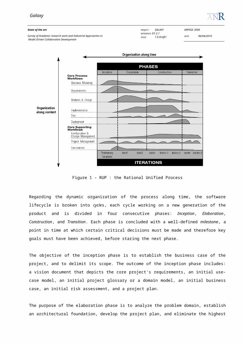
Galaxy
State of the art
Survey of Academic research work and Industrial Approaches to Model Driven Collaborative Development
PROJECT: GALAXYREFERENCE: D1.2.1ISSUE: 1.0 Draft1
ARPEGE 2009
DATE: 06/04/2010
For each of these two approaches, Avritzer et. al. give example process models (described with informal box-and-
arrow notation).
3.3 COLLABORATION SUPPORT STRATEGIES
In the various tools that have been proposed, in academia as well as in the industry, to support collaborative work, some
key technologies are recurring. A fair amount of research and development has gone in perfecting these technologies
over the years. This section explores some of the most relevant propositions for Galaxy.
3.3.1 Notification Management
Notification or awareness management is how developers are informed of the presence and actions of fellow
developers. It helps to close the gaps created by distance in a distributed development setting, and provide developers
with information relevant to their work. Notification strategies range from real-time notifications, to manual (ie non-
automated) information sharing with email for example.
The main challenge with notification management is the relevance of information. With basic effort, developers can be
flooded with any imaginable activity going on in the project. But this is of no use, if the information is of no use to a
particular developer, or of too low level to make sense of (knowing that a method has been renamed at the other end of
the world is less useful that being notified of a refactoring going on in some module).
The various information awareness tools provide can be classified into three categories [Cook, 2007]:
View awareness. This category contains artifact modifications which do not map immediately or directly to a
project’s semantic model. It includes physical proximity, view modification (ex: layout changes), textual
modifications and code neighborhoods.
Semantic model awareness. Includes semantic changes, impact reports, software metrics, and test case results.
Workflow awareness. All artifact modifications that are not related to the projects semantic model belong here,
for example bug catalogs and documentation changes.
Traditional version control systems delay notifications until a developer commits his work. Popular tools like SVN and
Git offer post-commit hooks, which can be used to build notification frameworks. With a bare-bone version control
system, developers usually have to manually check the repository for any new changes.
In [Cook et al., 2003], Cook et al. describe CAISE, a collaborative software engineering framework. CAISE is based on
a server and client architecture. The server maintains an always up to date model of the project, and each editor sends
changes made locally by developers. Every developer is instantly notified of any change made on his current artifact, or
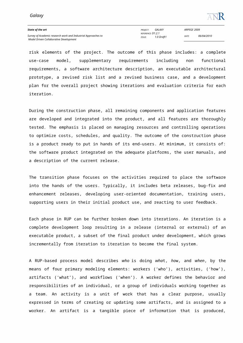
Galaxy
State of the art
Survey of Academic research work and Industrial Approaches to Model Driven Collaborative Development
PROJECT: GALAXYREFERENCE: D1.2.1ISSUE: 1.0 Draft1
ARPEGE 2009
DATE: 06/04/2010
a related artifact by another developer. To this end, the server has a continually updated parse tree of all artifacts, and
can automatically detect dependencies.
3.3.2 Update Management
To manage updates is to make sure all the implications of a change on an artifact are taken into account. Update
management is based on change detection and dependency resolution.
In traditional software development, change detection is usually done on a file-per-file basis, using modifications times,
that is, changes are taken into account only when a file is saved. There is usually no editor level support for changes, ie
a change in an editor buffer has no impact on other artifacts until the buffer is saved. Some IDE, like Eclipse can check
code on the fly (for syntax highlighting for example), and hot-reload code in a Virtual Machine (VM), but the later is
typically done only after saving. Usually, the editor offers hook so as to execute custom code whenever a file is
changed.
Various forms of the UNIX utility make have been used to track change propagation. Change propagation is all about
finding the artifacts affected by a change. In make, the dependencies are mostly static, and specified as file-to-file
relations. More recent tools like ant have built-in rules which cover most of Java development needs (compiling,
running tests, packaging, etc). But a smart environment can exploit the semantics of the language to enhance
dependency tracking (a Java editor for example can detect when a change in an interface or implementation impacts
some other artifact).
Update management can be done on-the-fly (that is, while editing an artifact), whenever a file is saved. On-the-fly
update management requires the cooperation of the editor (or modeling environment). In CAISE [Cook et al., 2003] for
example, a parse tree representing the manipulated artifact is maintained on the update management server, which runs
conflict management engines in real-time, and sends analysis results back to the editor. In ModelBus, [Sriplakich et al.,
2008] some editor actions are intercepted (loading, unloading, navigation), for change detection purposes.
3.3.3 Merging
Merging contributions is a necessary step when working with optimistic locking (that is, allowing concurrent edits to
the same artifact). As more than one person can work on an artifact at a time, there must be a way to integrate their
changes later. This challenge is more or less solved for text-based formats, as numerous diff (tools that can describe the
changes made to a file in a computer-readable format) exist.
Obviously, merging relies heavily on diff tools. There have been some interesting efforts toward diff (or delta)
algorithms for models [Mehra et al., 2005, Sriplakich et al., 2008]. Developing these new tools introduces new
challenges because of the mostly graphical nature of models.

Galaxy
State of the art
Survey of Academic research work and Industrial Approaches to Model Driven Collaborative Development
PROJECT: GALAXYREFERENCE: D1.2.1ISSUE: 1.0 Draft1
ARPEGE 2009
DATE: 06/04/2010
Merging requires the ability to identify changes made to an artifact. There are various ways a change to a file can be
identified:
With a line by line comparison. This is used in code-based version control systems, and is usually sufficient for
text-based artifacts.
Heuristic-based matching in graphs. This strategy has been used for models, but is not exact: there can be
false-negatives and false-positives
ID-based matching in graphs. This works by assigning a unique ID to each element. The approach has been
used in ModelBus [Sriplakich2008ModelBus], and requires a specific adapter for each editor used.
With help from an editor. When possible, this can lead to a better capture of change semantic. An editor for
example can precisely identify a large refactoring as one conceptual change, instead of a bunch of seemingly
unrelated modifications.
3.3.4 Annotations
Even before the emergence of digital documents, annotations have always been used on simple papers in form of
comments or post-it enhancing the share of knowledge between members. This practice has also been adopted in virtual
spaces in order to help distant members to collaborate and make decisions. In this context, annotations don’t only
present simple objects, but they also constitute an activity of mediated communication and share of information
fostering the exchange of ideas, opinions and propositions.
3.3.4.1 Definition
There is no consensus what an annotation is because it was used in many fields and for different objectives. In general,
it can be seen as a fragment of information added to a part of content in order to enable the share, the access and the
interpretation of information. It can involve as various facets such as a tag for labeling in web 2.0, an index key to
facilitate research of files and finally a piece of information to explicit the target text. In this work, we will deal
especially with this final function introducing the term of cognitive semantic annotation. Usually, there are three kinds
of annotation: simple metadata, computational semantic annotation and cognitive semantic annotation. The first one just
presents general information about the annotated fragment. The second one is mainly used in semantic web enabling
communication between systems where the annotations are in general addressed to software programs. Finally, the third
one deal with the meaning and the representation of an annotation and it has two dimensions: individual and collective.
It is essentially addressed to human beings.
To highlight the parts and properties that constitute an annotation, we give some important definitions. [Leech 97]
defines an annotation as an added value consisting in the contribution of interpretative information to raw data. In the

Galaxy
State of the art
Survey of Academic research work and Industrial Approaches to Model Driven Collaborative Development
PROJECT: GALAXYREFERENCE: D1.2.1ISSUE: 1.0 Draft1
ARPEGE 2009
DATE: 06/04/2010
domain of human-machine interface, [Baldonado & al 00] makes a distinction between a document and an annotation.
They define the annotation as “a comment on an object that the commentator wants to be perceptibly distinguishable
from the object itself, and that the reader interprets it as perceptibly distinguishable from the object itself”. They focus
here on the nature of representation and interpretation that characterize an annotation comparing to the target document.
In the cognitive domain, [Veron 97] defines an annotation as “a track of reader’s mental state and of his reactions
towards the document”. In design science, researchers define an annotation as a production of text or schema on the
main document which has already an official status in the design project.
3.3.4.2 Annotation properties
According to some studies, all the annotations are characterized by certain common elements. The following figure
depicts some of annotation’s properties described below.
Figure 7: Annotation properties
The target: It is the object to which the annotation refers. It can be a document, a fragment of document (text or
graphic) or a set of documents. It constitutes the context in which the annotation can be interpretable. The
annotation can be integrated in the document or can be separated from it.
The anchor: it is the object that links an annotation to the target at the visual level. It can be for example a
simple arrow or a note on the bottom of the document.
The form: an annotation can be presented in various forms such as text, graphic, video, etc. In this work, we
just focus on textual and graphic form.

Galaxy
State of the art
Survey of Academic research work and Industrial Approaches to Model Driven Collaborative Development
PROJECT: GALAXYREFERENCE: D1.2.1ISSUE: 1.0 Draft1
ARPEGE 2009
DATE: 06/04/2010
The content: it refers to the information that the annotator wants to deliver. It can be structured, semi-
structured or a free composition. Structured content can facilitate the use and the interpretation of the
annotation. In the case of semantic web, the content is in general structured and managed by domain’s
ontology.
The actors: they can be an annotator or a reader. The annotator can either be or not the document’s author. The
reader can be the document’s author when the annotation has an individual dimension, and can be another
person when the annotation has a collective dimension. In this last case, a particular attention is paid to the
annotation’s form and structure. Indeed, when the readers have disparate skills and are from different
disciplines, it is prominent to ensure the clarity of annotation which has to be easily interpretable. In this work,
in the context of collaborative design, we deal essentially with collective dimension and public use of
annotation.
The annotation is also characterized by its role that varies according to the purpose of use. Many studies have addressed
different functions and we give hereafter a not exhaustive summary of primary ones:
Reminder: the annotation serves to memorize significant parts of documents. [Bringay 06] stipulates that the
action to mark a document facilitates the process of internalizing knowledge of document. It also enables
pointing out key words that help actors to remember what they consider important in the text. And finally, it
presents a means to mark the document's logical structure (chapter, section, etc), and so the actor will be able
to quickly collect and reinterpret this structure.
Interpretation and share of knowledge: in order to make shared information explicit and avoid ambiguities,
authors employ annotation. In this context, [Marshall 97] reports three types of annotation: the first one used
to identify and define difficult words, the second one used to underline the parts that characterize a document,
the third one used to interpret the meaning of a document’s fragment. Likewise, [Bringay 06] distinguishes
between two kinds of interpretation : the first one called “think interpretation” consists in adding information
derived from annotator experiences like notes, questions, comments, etc; the second one consists in
reformulation of document’s content without adding new information. This distinction correlates with this of
[Virbel 93] who classifies the interpretation into comment or reformulation of the content.
Planning of actions: Some annotations are dedicated to organize actions and tasks in a workspace [Azouaou &
al 03].
Classification and structuring: some annotations are used to structure the document into different parts. [Virbel
93] defines eight objectives of annotation. Some of them used to organize objects into hierarchical structure
and to clarify components of the logical structure.
Galaxy
State of the art
Survey of Academic research work and Industrial Approaches to Model Driven Collaborative Development
PROJECT: GALAXYREFERENCE: D1.2.1ISSUE: 1.0 Draft1
ARPEGE 2009
DATE: 06/04/2010
3.3.4.3 Cognitive and computational annotation
Annotation can be classified into two categories according to the type of its recipient: a human or software agent. For
the first agent, the annotation must be visible, explicit and easily interpretable. It stands for cognitive annotation. But,
for the second agent, it is employed to describe computer resources to be exploited for different uses like information
retrieval, dynamic composition, etc. It stands in this case for computational annotation and adopts a formal language or
defined metadata. In this work, we deal specially with the first category where all the actors are human agents.
3.3.4.4 Annotation for Semantic web
Semantic annotation results in the introducing of a semantic information over-layer which gives a meaning to
documents’ content. The web world contains a great number of distributed documents and destined for different
persons. This strong heterogeneity requires process automation by software agents to treat documents and make
seamless the access to information. This has led to the creation of an intelligent document concept possessed of
awareness about what it contains. Awareness here is modeled through a domain ontology which provides information to
be integrated in the annotation. This last is destined to ensure communication between machines in order to be able to
interpret annotation content relying on relations between concepts that constitute the ontology (description of terms and
their relations). A machine has so the capability to formulate an idea about the concept (e.g. person) to which refers a
specific term (e.g. student). On one hand, this has resulted in a major improvement in information retrieval systems
which become able to ensure an efficient search of document based on ontology. Indeed, each document is indexed
using annotation whose the content can establish a semantic links between all indexed documents. Then, the ontology
enhances the detection of semantic relations between heterogeneous information resources, and so it enhances the
retrieval of documents that are semantically linked with the searched word or information. For instance, ontology of
tourism domain can be used to retrieve documents referring to hotels in France. On the other hand, this kind of semantic
annotation has also improved the interoperability between information systems and heterogeneous source using
integration mechanisms.
3.3.4.5 Annotation for shared documents
The exploitation of annotation gets a collective dimension when the documents are shared between different members.
In this case, [Marshall 98] observe that the annotated used books are more looked for by readers because they convey
an appreciated value for them. By the increase of technical tools supporting documents sharing, annotations present a
valuable feature that has to be integrated in digital documents. Indeed, [Marshall & al 99] underline the role of
annotation which seems beneficial to highlight the important parts and the areas of consensus in a document. This can
lead to the detection of ideas’ divergence or convergence between readers on significant points. The authors also uphold
the role of annotation to reduce the time of reading. In fact, they observe that the actor takes less time when the
document is annotated. Furthermore, some of advantages that are provided by the use of annotated digital documents

Galaxy
State of the art
Survey of Academic research work and Industrial Approaches to Model Driven Collaborative Development
PROJECT: GALAXYREFERENCE: D1.2.1ISSUE: 1.0 Draft1
ARPEGE 2009
DATE: 06/04/2010
can be pointed out comparing to the use of simple papers. For example, information retrieval mechanism can be
performed enabling the direct access to the indexed concept which saves up the cost of search. Nevertheless, one issue
arises from annotations sharing consisting in the understanding of an annotation created by another person, which refers
to the term “intelligibility”. In fact, annotators didn’t want to make effort to explicit their annotations which become
difficulty interpretable. This lack of explanation leads to the loss of annotation advantage while the ability of
interpretation is a fundamental element in a sharing content [Marshall & al 99]. In consequence, this issue imposes a
need to develop functionalities in order to optimize the editing and the use of annotation. The challenge is to help
annotators and to reduce their efforts to make annotations explicit. This will be a significant asset to minimize the
editing time. Hence, benefits can be ensured at time level and interpretation level. But, some annotations don’t need an
effort to be interpretable as they present a simple reminder, evaluation, etc. So, what are mechanisms that can be
integrated in annotation feature to attain these benefits without affecting the intelligibility of easily interpretable
annotation?
3.3.4.6 Annotation for collaborative design
Annotation activities have always been occurred and shared on technical papers during collaborative design meetings.
They allow designers to express explicitly their opinions and discuss ideas where the design process is a rich space to
whip up viewpoints’ confrontation. Hence, it is also necessary to enable annotation when meeting’s actors are distant
and they communicate synchronously or asynchronously through virtual systems. Indeed, in these last situations, some
markers are missing for designers comparing to the situation where they are co-located. Some of these markers are the
gestures indicating that the interlocutor has understood what it had been said and the signs indicating his rejection or
agreement of solutions. Many researchers have therefore proposed some solutions like annotation which become a part
of systems destined to computer aided design. A progress has been made in this field where a more structured
annotation than a simple textual one was invented to enhance the share of information. The content of annotation can
now be interpreted by machines which get abilities to identify entity’s constituents. It can be evenly interpreted by
human beings giving rise to cognitive semantic annotation which is the subject of this work.
In a collaborative design process, group members’ interactions consist mainly in design acts such as proposition,
evaluation, comment, decision, etc. Each member need to draw up an overview about the progress state concerning each
part of project in order to be cognitively synchronized with other members. This progress is a construction made up by
the concert of designers’ acts through solution elaboration, argumentation and evaluation. Moreover, a product cannot
attain a mature evolution and an approval state when it hasn’t been manipulated and reviewed by designers from
different expertise. Hence, actors’ cooperation is an important key to ensure a pertinent design that needs a collective
understanding about the design’s state. In general, this cognitive synchronization is mainly established during face to
face meetings. However, when actors are distant and communication becomes mediated, the annotation plays an
important role to build an overview about the progress state of each product. Furthermore, another advantage is also
provided by annotation capability mentioned by [Marshall & al 99]. In fact, it enhances collaboration process by
bringing together different readers. Indeed, when an actor annotates documents, he highlights his interests and his

Galaxy
State of the art
Survey of Academic research work and Industrial Approaches to Model Driven Collaborative Development
PROJECT: GALAXYREFERENCE: D1.2.1ISSUE: 1.0 Draft1
ARPEGE 2009
DATE: 06/04/2010
activities which may be convenient with those of another actor and captivate his attention. This is mainly occurred in
collaborative web.
In the thesis [Lortal 06], the annotation is referred to a metadata, and also to a way of negotiating boundaries to create a
common referential and to promote mutual awareness of annotators, enriching semantically a document. Moreover, the
author stated that is possible to track the logic of communication to understand design steps in the document through the
indexation of annotations. Indeed, it is possible to integrate annotations dealing with argumentative interactions into one
document underlining so the design rationale about annotated product or model. This is a valuable feature that allows
designers to list all actions made on specific product and evaluate its progress state. On the other hand, [Lortal 06] states
that the annotation is contextualized by its textual environment and its production environment. The former consists in
its body (content) and its target text (the document to which it is anchored), its form and its function. The latter is
represented by its actor (the author and the reader) and his role. This raises questions about the nature of the target
document and the content of annotation which best respond to its function. Besides, when actors annotate the same
fragment and annotations are stocked, this generates problem on visibility level which requires anchoring and storage
control. Moreover, the annotator’s identity presents an important key of annotation. So, in a collaborative design, the
actors need to know who the annotator is and what his expertise is to best comprehend the production environment of
annotation.
According to [Zacklad & al 03], the cooperation process includes episodes of deliberation and confrontation allowing
the review of solution representation’s state and benefiting from evaluation of other participants. This mutual exchange
will generate another constraints and alternative proposals. In this context, the authors highlight the role of annotation in
order to ensure knowledge capitalization and management. They make distinction between two functions of annotation:
criticize and plan. For criticize function (e.g.; “this bar is not well positioned”), the annotation is dedicated to
argumentative communication on the target product to evaluate it and propose solution. For plan function (e.g. X must
work on this point later), the annotation is dedicated to organize and coordinate between actors for project management.
This distinction seems relevant in all collaborative design processes whatever the field because participants’ interactions
concern mainly design product or group management.
3.3.4.7 Annotation for communication
[Tazi & al 04] have studied annotation act from the perspective of speech act theory created by Austin in 1962 in his
publication How to Do Things with Words [Austin 62], and formalized by Searle [Searle 69]. This theory claims that, in
a communicative speech, people do not just utter words, but also they try to inform, request, convince, etc. In other
words, the speech act carries the speaker’s intention which is implicated to determine what he wants to express by
formulating some words. In this context, the speech act presents a means of action where the speaker delivers a message

Galaxy
State of the art
Survey of Academic research work and Industrial Approaches to Model Driven Collaborative Development
PROJECT: GALAXYREFERENCE: D1.2.1ISSUE: 1.0 Draft1
ARPEGE 2009
DATE: 06/04/2010
which has a set of effects manifested by the execution of some actions. The authors applied this theory in written
communication where the author plays the role of the speaker and the writing acts involve in cognitive process. At this
level, annotations serve to explicit clearly authors’ intention, and so they are presented in form of an intentional
structure that has been defined and based on four parameters: Action A, goal G, means M and reason R. Indeed, while
writing, the agent has an intention to perform an action A in order to achieve a goal G, by the means M and for some
reasons R. this model highlights the notion of intention’s effect generated by written act and manifested by an action.
3.3.4.8 Ontology
Generally, ontology is defined as a network of concepts organizing and modeling some knowledge ensuring a certain
level of abstraction. Gruber proposes a reference definition: “An ontology is an explicit specification of a
conceptualization of a knowledge domain”. It is a formalization of knowledge and it is also a representation of a shared
and consensual conceptualization which highlights the collaborative efforts to construct ontology. This network consists
in a set of objects that are characterized by some properties and linked between them through different relations. Thus,
the construction of ontology requires the analysis of objects’ dependency and characteristics to define the properties and
the kinds of relations. These last can be semantic or subsumption relations. The first refers to the relationship between
two or more words based on their meaning. For example, “bike” and “bicycle” are synonym words. The second refers
to the relationship of implication linking the more specific to more general concepts leading to a hierarchical taxonomy.
For example, a train is more specific concept that “vehicle”. The following figure illustrates the different elements that
constitute an ontology (example of pizza provided with Protégé tool).
Figure 8 : the pizza ontology
As depicted in this figure, the ontology is composed of:
Individuals: they are also known as instances and they represent the entities of the domain.

Galaxy
State of the art
Survey of Academic research work and Industrial Approaches to Model Driven Collaborative Development
PROJECT: GALAXYREFERENCE: D1.2.1ISSUE: 1.0 Draft1
ARPEGE 2009
DATE: 06/04/2010
Concepts (classes): they constitute a group of individuals which have similar characteristics (they are presented by
circles in figure 4). For instance, OnionTopping class includes all pizzas that have onion on its topping. It belongs
to class of pizzas which have vegetable topping. A concept can present any term from different context, but it is
essential to build a logic and structured presentation.
Relations: they present the types of interaction between classes like a hierarchical relationship. They can support
many characteristics like reflexive, functional, transitive, etc.
Axioms: they are specified for defining true propositions in order to add a logic layer and reasoning to ontology.
Domain ontology should be designed to harmonize the vocabulary between annotators in a manner that it will reduce
ambiguities and enhance communication between designers.
3.4 COMPUTER SUPPORTED COLLABORATION TOOLS
Computer supported cooperative work addresses “how collaborative activities and their coordination can be supported
by means of computer systems.” It combines the understanding of the way people work in groups with the enabling
technologies of computer networking, and associated hardware, software, services and techniques. A collaborative
working environment supports people in their individual and cooperative work.
The following applications or services are considered elements of a collaborative working environment : e-mail, instant
messaging, application sharing, videoconferencing, collaborative workspace and document management, agenda
sharing, task and workflow-management, wiki group or community effort to edit wiki pages, blogging where entries are
categorized by groups or communities or other concepts supporting collaboration.
3.4.1 Web-based collaborative tools: Groupware, Wiki, CMS.
3.4.1.1 Groupware
A groupware is software aiming at creating such an environment for communication, sharing of information and
coordination within a group of individuals. It is a collaborative space for working groups. It's main functionalities are
agenda, address book, storage space of shared documents, web page edition, access rights management, etc. It can also
support shared schedule, task management and project management, forums, newsgroups and mailing lists,
collaborative work support, wiki, etc.
Some groupwares are: Msexchange (http://www.msexchange.org), Desknow http://www.desknow.com), Cronopolys
(http://chronopolys.xwiki.org), Sharepoint, (http://sharepoint.microsoft.com ), Simple Groupware Solutions,

Galaxy
State of the art
Survey of Academic research work and Industrial Approaches to Model Driven Collaborative Development
PROJECT: GALAXYREFERENCE: D1.2.1ISSUE: 1.0 Draft1
ARPEGE 2009
DATE: 06/04/2010
(http://www.simple-groupware.de/cms/), OBM (http://obm.aliasource.fr), PHPProject
(http://www.phprojekt.com ), eGroupware (http://www.egroupware.org)
3.4.1.2 Wiki
A wiki is a management system for website content, for which every (authorized) visitor can freely and easily
modify pages. It allows communicating and spreading (broadcast) information quickly, to structure this information to
allow to navigate it comfortably and to modify its contents in a collaborative way. I ts main functionalities are content
display, modification of the contents (publishing), modification, addition, deletion and formatting, linking, image
insertion, traces of modifications, consultation of the history of successive modifications (by page, by contributor),
return to a former version, access restrictions administration, analysis of the hypertext links, interface with the system
(creation and management of accounts users, management of the preferences, etc.). Ward Cunningham and Bo Leuf, in
their book “The Wiki Way: Quick Collaboration on the Web” described the essence of these wiki concepts. In the
Ward Cunningham original description, a wiki is “the simplest online database that could possibly work”. “Wiki” is a
Hawaiian word meaning "fast”.
Wiki software is a type of collaborative software that runs a wiki system, allowing web pages to be created and edited
using a common web browser. It is usually implemented as an application server that runs on one or more web servers.
It needs an Internet browser for display, edition tools for publishing, identification tools (date and author of the
modification), and version management, a database for storing the contents and the versions, system tools allowing to
manage an account, to authenticate a user, for users management, modification analysis tools, hypertext links analysis
tools.
Wikis are typically powered by wiki software and are often used to create collaborative websites, to power community
websites, for personal note taking, in corporate intranets, within enterprises and in knowledge management systems.
Wikis may exist to serve a specific purpose, and in such cases, users use their editorial rights to administrate the content
and control changes (for instance remove material that is considered "off topic"). The most illustrative example for this
use is the collaborative encyclopedia Wikipedia (www.wikipedia.org).
Examples for most common wiki software are: MediaWiki, JSPWiki, PhpWiki, PMWiki, XWiki, DocuWiki
3.4.1.3 Content Management System
A “Content Management System” (CMS) represents the collection of procedures used to manage work flow in a
collaborative environment. Particularly, a CMS is a web software package which allows to manage and to develop on-
line a dynamic website or multimedia applications (pages create on the fly from the contents of a database):
management system of web contents, system of web publication. It allows for a large number of people to contribute
and share data having support for storing and retrieving data. An user management mechanism is integrated, therefore it

Galaxy
State of the art
Survey of Academic research work and Industrial Approaches to Model Driven Collaborative Development
PROJECT: GALAXYREFERENCE: D1.2.1ISSUE: 1.0 Draft1
ARPEGE 2009
DATE: 06/04/2010
controls access to data, based on user roles.(what information each user can view or edit, ex : authors, managers, and
administrators). Basic functionalities that are provided by CMS are:
dynamic management of web content,
project management,
document versions management.
There are also additional possible extensions to add new features to the site such as scheduling, calendar, sending and
downloading files, internal messaging system, forum, chat, etc.
Some CMS are: PhpNuke (http://phpnuke.org/index.php), Joomla (http://www.joomla.org/), Xaraya
(http://www.xaraya.com/), Mambo (http://www.mamboserver.com/) Apache Jetspeed
(http://portals.apache.org/jetspeed-2/), SPIP(http://www.spip.net/rubrique25.html)
3.4.2 Online Collaborative Applications (Documents, Calendars, Conferencing etc.)
A collaborative application is a form of collaborative software application that allows several people to participate to
online conferences, to edit, to store and to access documents using different computers. The documents will be shared
by a group of registered users. Such applications support the management of versions of shared documents.
Online office applications are automation software suite, including programs allowing collaborative work, on text
document, spreadsheet, and presentation. Such applications allow the registered users to create, import, modify
document, without any software installed on their computer. An internet connection is enough for finding one’s
workspace. One can share files with other users, who can possibly modify them in real time, or to turn them public by
associating a URL address. For instance GoogleDocs (Google), Office Web Apps (Microsoft), Zoho are such web-
based office tools.
Online calendar applications allow people to publish and share commons calendar in order to work together. Calendars
can be public or shared with specific people. A range of sharing permission controls help maintain security and privacy.
Examples of such applications are: GoogleCalendar, Wichtime.com.
Web conferencing is used to conduct live meetings, training, or presentations via the Internet. Typically, these tools
provide core functionality such as screen sharing, voice and video conferencing. Web conferencing is often sold as a
service, hosted on a web server controlled by the provider. Notable web-conferencing tools service providers are:
WebEx, Adobe Connect, IBM Lotus, …

Galaxy
State of the art
Survey of Academic research work and Industrial Approaches to Model Driven Collaborative Development
PROJECT: GALAXYREFERENCE: D1.2.1ISSUE: 1.0 Draft1
ARPEGE 2009
DATE: 06/04/2010
3.4.3 Collaborative IDEs (Jazz, etc.)
3.4.3.1 IBM-Jazz
In the paper “Collaborative development environments”, Grady Booch and Alan W. Brown, from Rational Software
Corporation (owned by IBM), laid out the vision that will later materialize into the Jazz platform. The vision stems from
the observation that producing software in an inherently collaborative activity, in which “all the
stakeholders of a project – even if distributed by time or distance – may negotiate, brainstorm, discuss, share
knowledge, and generally labor together to carry out some task, most often to create an executable deliverable and its
supporting artifacts” [Booch & Brown, 2003]. A virtual environment that could host and facilitate the fore-mentioned
interaction is called a “Collaborative development environment”.
While Booch & Brown recognize that various tools to support such interactions have always existed (from email and
chat to message boards, issue trackers, source control systems, etc.), they claim that “Communities of practice are
fragile things that can flourish only given the right balance of technology and user experience […] It is the supportive,
integrated nature of a CDE that distinguishes it from the variety of disparate functional products typically in use
today”.
The ultimate goal is thus to create a “frictionless surface” that could eliminate or automate non-creative activities, and
encourage creative and high-band modes of communication between a project’s stakeholders. If the goal of Eclipse is to
improve the productivity of the individual developers, a collaborative development environment seeks to improve the
productivity of the team as a whole.
After surveying some notable product which exhibits some of the desired capabilities, the authors propose a list of
features a collaborative development environment should have, organized in three main groups:
Coordination features (calendaring, scheduling, events management, dashboards, metrics, searching, etc.)
Collaboration features (discussions, meetings, instant messaging, pooling, shared whiteboards, etc.)
Community building features (protocols and rituals, self-publication of content, self-administration of projects,
scope and leadership, etc.)
IBM launched the Jazz platform (http://jazz.net) to implement the above described vision. It is pitched as the next
evolution of the Eclipse platform. The Jazz platform is the technical foundation on which a couple of product rest:
Rational Team Concert (work item tracking, source control, continuous builds, process support)
Rational Quality Manager and Rational Test Lab Manager (application lifecycle management, testing)
Rational Requirements Composer (requirement definition)
Rational Project conductor
Rational Insight
Galaxy
State of the art
Survey of Academic research work and Industrial Approaches to Model Driven Collaborative Development
PROJECT: GALAXYREFERENCE: D1.2.1ISSUE: 1.0 Draft1
ARPEGE 2009
DATE: 06/04/2010
Rational Build Forge
Rational Asset Manager
The Jazz code is not open source. However, an “express” version of Rational Team Concert is available for small teams
(10 members max). API documentations are available to add extensions to the various components of the Jazz platform.
There is currently no explicit support for metamodeling in Jazz.
IBM pitches Jazz as follows: “Jazz is designed to transform how people work together to build software,
making software delivery more collaborative, productive, and transparent. You can think of Jazz as an
extensible framework that dynamically integrates and synchronizes people, processes, and assets associated
with software development projects.” Jazz is thus heavily focused in the human aspects of collaboration,
while Galaxy is mainly concerned with (large) data exchange and management.
3.4.3.2 CoDesign
CoDesign is a project jointly developed by Infosys Technologies Limited (Bangalore, India) and the University of
Southern California, and described as a “highly extensible collaborative software modeling framework”. CoDesign is
built around the observation that, in SCM-based distributed collaboration infrastructures, conflicts can be detected only
after a commit, when it is usually too late for an automated and/or efficient resolution. It is therefore useful to detect
conflicts in real-time, and notify the appropriate designers, so as to enable frictionless collaboration in geographically
distributed work settings [Young Bang et al., 2010].
CoDesign’s main contribution is an “extensible conflict-detection framework for collaborative modeling”. The
framework is built so as to support seamless integration of off-the-shelf conflict detection engines and modeling tools
by appropriate adapters. It uses server-client architecture, based on messaging and event-processing. Modeling tools
send event corresponding to edition action to the server, which uses conflict detection engines to match conflicting
actions. The conflict is automatically resolved if possible, or notifications are sent back to the modeling tools, which
inform the designers.
Three main conflict types are recognized by CoDesign:
Synchronization conflicts: A designer makes an edition action which does not make sense in the context of
another edition action made by a remote co-worker (like adding an attribute to a removed class). These happen
when the event corresponding to a remote edition action is not received on time.
Syntactic conflicts: Syntactic metamodel rules (like cardinalities) are violated by the cumulated effect of
concurrent edits
Semantic conflicts: Concurrent edits result in the violation of a consistency rule, external to the metamodel and
explicitly specified with OCL for example.

Galaxy
State of the art
Survey of Academic research work and Industrial Approaches to Model Driven Collaborative Development
PROJECT: GALAXYREFERENCE: D1.2.1ISSUE: 1.0 Draft1
ARPEGE 2009
DATE: 06/04/2010
While downloads are not yet available (http://softarch.usc.edu/~ronia/codesign/#download), CoDesign has already
been integrated with Drools to detect synchronization conflicts, GME’s metamodel checker for syntactic conflicts, and
GME’s OCL checker for semantic conflicts.
3.4.3.3 Syde
Syde is a tool from the University of Lugano, Switzerland, which, like CoDesign, detects conflicts in real-time in a
distributed development setting. Unlike CoDesign, Syde focuses on code (instead of models) and is implemented as a
plugin, exploiting the rich Java AST (Abstract Syntax Tree) manipulation and refactoring capabilities of Eclipse.
The tool has a server-client architecture, with a central server storing the abstract syntax trees of each developer
workspace on the server. The server also hosts conflict detection engines which work by comparing the different AST.
The AST are update with change information sent from each developer’s machine by specialized plugins. These change
information, unlike the diff functionality of popular version control systems, are not line-based, but rather AST-based,
so capture much more semantic information. Better, the powerful refactoring capabilities of the eclipse editor help to
capture substantial changes to a project as single conceptual information. This helps to keep the amount and relevance
of awareness information down [Hattori & Lanza, 2010].
One major contribution of Syde (besides AST-based changes) is the various awareness facilities. A plugin can help
developers visualize the latest classes changed, with colors indicating the developer who made the change, and size
indicating the amount of activity on that element for example (word cloud). Another plugin can show the recents
changes and their authors as annotations or tooltips right in the Eclipse editor.
3.4.3.4 ModelBus
ModelBus [Sriplakich et al., 2008] is a “model-driven tool integration framework”, originally developed in the context
of the MODELWARE project, and currently maintained as part of the MODELPLEX project. ModelBus was available
in the MDDi Eclipse project, which has been archived since August 2008. Current version is available at modelbus.org.
On the one hand, ModelBus is an interoperability layer which allows a modeling tool to use the services of another tool.
The functionality is RPC-based, with a call-by-copy-restore semantic (that is, a copy of a model is sent to a tool, the
tool updates the model, the modified version is returned, and replaces the original). ModelBus allows tools to send only
some parts of a model, to improve performance (less data to copy) and access control (send only the part that the
receiver is allowed to view/modify). Model fragments are defined by a root node and a collection of nodes that can be
included in the fragments: only nodes that can be reached from the root and belong to the collection are included.
On the other hand, ModelBus is a distributed collaborative model editing environment; designed after centralized

Galaxy
State of the art
Survey of Academic research work and Industrial Approaches to Model Driven Collaborative Development
PROJECT: GALAXYREFERENCE: D1.2.1ISSUE: 1.0 Draft1
ARPEGE 2009
DATE: 06/04/2010
version control systems like SVN and CVS. Models are stored in a central repository as XMI files; which allows
reusing part of the functionality of CVS, a file-based version control system. Developers copy (part of) the repository to
their local workspace, make modifications, and send their updates to the repository.
Merging and conflict resolution in ModelBus is based on deltas, which are models containing the changes related to a
pair of models: the original model, and the modified one. ModelBus offers delta calculation (generation of delta
models), conflict detection and resolution (based on delta comparison) and delta integration (aka merging). These are
implemented on the MOF level using Eclipse EMF, which makes ModelBus compatible with any MOF-based model.
Delta calculation in ModelBus relies on the association of a unique ID (an UUID actually) with each node in a model.
ModelBus can unambiguously refer to a model node using the (relative) path of the model, and the node’s id, as in
“module1/model2.xmi#node-uuid”. Links between nodes are encoded using paths and IDs, allowing ModelBus to
detect deletions, additions, modifications, and even element moving between models (refactoring).
Conflict detection is handled by comparing deltas pair-wise. Whenever a developer commits his changes to the
repository, two deltas are calculated:
a first delta, d1, between the current version of the model in the workspace, and the version the developer used
as the starting point of his work
a second delta, d2, between the current version of the model in the repository, and the version the developer
used as the starting point of his work (those two versions can be different if another developer committed on
the same model in the mean time)
The two delta models, d1 and d2, are compared to detect conflicts (multiplicity and association order, mostly related to
inter-model links). ModelBus can resolve conflicts automatically (giving priority to the latest changes) or let the
developer decide interactively what to do with each conflict. Additionally, ModelBus offers an API which can be used
to implement custom automatic conflict resolutions strategies.
ModelBus distinguishes between the Workspace Manager, which communicates with the repository, and the Tool
Adapter, which bridges between the modeling tool and the Workspace Manager. Tool Adapters keep track of IDs by
maintaining a table mapping node IDs to node memory locations, a providing modeling tools with model loading and
model saving functions, so that ID management can be transparent. Tool Adapter also offer “scalable model loading”,
that is the ability to defer loading a model into memory until a link (inter-model link) leading to that model is followed.
This is only possible when the editor offers hooks to intercept navigation towards unloaded models, and this is the case
in EMF.

Galaxy
State of the art
Survey of Academic research work and Industrial Approaches to Model Driven Collaborative Development
PROJECT: GALAXYREFERENCE: D1.2.1ISSUE: 1.0 Draft1
ARPEGE 2009
DATE: 06/04/2010
3.4.4Version Control
In this section, we summarize the literature on Revision Control Systems (RCS) relevant to Galaxy. We first structure
the field by proposing dimensions along which to classify such systems. We then survey RCS that focus on controlling
revisions made to textual software artifacts such as source code and natural language documentation. We then survey
academic research on RCS that focus on controlling revisions made to graph-based models such as those that follow an
Object-Oriented (OO) metamodel such as Ecore [Steinberg et. al., 2008] or MOF [OMG, 2006].
3.4.4.1 Classification dimensions of RCS
An RCS provides a variety of services that improves the productivity of teams that collaborate to construct software
artifacts. There is no universally accepted set of RCS services. However, the following services are generally expected
to be provided by an RCS together with complementary tools able to interoperate in synergy with the RCS ( e.g., plug-
ins):
History recording: keep track of who made which revision to what artifact when and with what purpose;
Revision roll back: allow seamless backtracking to past versions of any artifact; Branch handling: allow efficient forking and subsequent merging of concurrent
development branches; Artifact comparison (often called diff): point out the differences between two artifacts,
generally with respect to a third artifact from which the two being compared independently evolved;
Conflict detection: identify among artifact differences those that prevent merging the artifacts without violating constraints defining correct syntax, well-formed structure or consistent semantics in the merge result.
The first dimension to classify RCS is the data structure used to represent the software artifacts under revision control.
The oldest RCS [Chacon, 2009] [Collins, 2008] were developed for code-driven engineering. They thus focus on
controlling changes made to text files that generally contain source code or natural language documentation. The recent
advent of MDE triggered the appearance of RCS [Murta et. al., 2007] that focus on controlling changes made to graph-
based models that are linguistic instances of OO metamodels. In such graphs, model elements are nodes and references
between model elements are vertices. One key reason that makes controlling graph-based model revision more complex
than controlling text file revision is the format diversity required by the former. A single text file serve two functions:
supporting edition actions by developers and supporting persistent storage and retrieval by RCS. In contrast, graph-
based models generally use one graph to support edition actions by developers and another distinct graph to support
persistent storage. This difference is illustrated in Error: Reference source not foundFigure 1 - RUP : the Rational
Unified Process. The left-top corner shows the graph representing the concrete visual syntax of a very simple UML
model that contains a single class and a single auto-association. This graph represents the user view of the model under
development. It is this graph that developers revise through GUI provided actions of the CASE tool they use. Contrast
this graph with the one shown at the bottom of the same figure. This other graph represents the very same model, but in
the distinct format used internally by the CASE tool to persistently store and revise this model. It is an instance of the

Galaxy
State of the art
Survey of Academic research work and Industrial Approaches to Model Driven Collaborative Development
PROJECT: GALAXYREFERENCE: D1.2.1ISSUE: 1.0 Draft1
ARPEGE 2009
DATE: 06/04/2010
abstract syntax of the modeling language in use, in this case the UML. A simplified subset of the UML metamodel that
defines this abstract syntax is shown at the top–right corner of the same figure. Note the structural mismatch between
(a) the user-oriented concrete syntax graph that contains only one node and one vertex and (b) the tool-oriented abstract
syntax graph that contains four nodes and four vertices. The advantage of the former is its visual conciseness. The
advantage of the latter is that it contains exactly one object per model element1. As a graph of objects instances of
metamodel classes it can be persistently stored and exchange between tools across a network as a binary file, or
serialized as a textual file (e.g., following for the XMI [OMG, 2007] serialization standard). Whereas an RCS for code-
driven only needs to control revision of a single text file for each artifact, an RCS for MDE needs to control consistent
revisions of multiple, subtly cross-constrained graphs (concrete vs. abstract syntax graph, model vs. metamodel graph,
etc.), each one with their various graphical display, persistent storage and interchange formats (image, binary object,
XML etc.).
The second dimension along which to classify RCS is how they store the revision history. The first distinction along
this dimension is between snapshot and delta approaches. The former simply stores a full copy of each version,
whereas the latter only the store the differences (or delta) between one version and its parent(s) version(s) (while each
version within a single development branch as a unique parent, a version resulting from a branch merge has several).
The general advantage of the snapshot over the delta approach is its simplicity and higher speed to navigate among
versions and branches. Its general drawback is its higher space requirement. Falling memory costs make the snapshot
approach more scalable by the day.
1 Abstracting from the objects that represent in the tool the visual rendering of each model element..

Galaxy
State of the art
Survey of Academic research work and Industrial Approaches to Model Driven Collaborative Development
PROJECT: GALAXYREFERENCE: D1.2.1ISSUE: 1.0 Draft1
ARPEGE 2009
DATE: 06/04/2010
UmlVsEcorepackage Data[ ]
+aggregation : AggregationKind
Property
+lower : Integer+upper : UnlimitedNatural
MultiplicityElement
aggregation = nonelower = 0name = "r1"upper = *visibility = public
r1 : Property
aggregation = nonelower = 0name = "r2"upper = *visibility = public
r2 : Property
+name : String+visibility : VisibilityKind
NamedElement
name = "a"visibility = public
a : Association
name = "C"
c : Class
compositesharednone
<<enumeration>>AggregationKind
protectedpackage
privatepublic
<<enumeration>>VisibilityKind
AssociationClass
C
+ownedAttribute
* 0..1
+memberEnd
2..*
+a
+r1
*+r2 *
Figure 9 - User-oriented vs. storage-oriented graph representations
Delta approaches are further sub-categorized in structural and action-based deltas. The former stores pairs of sub-
structures that differ in the current version and (one of) its parent version, whereas the later stores a minimal revision
action sequence which, when applied to (one of) the parent version results into the current version [Blanc et. al., 2009].
In an MDE context, revision actions include changing the value of a model element attribute, adding and deleting a
model element or a reference between two such elements. Two action sequences are considered equivalent if their
application on any given artifact yields the same revised artifact. The action sequence stored in action-based delta
approaches need not be the one executed by the developer, it can an equivalent, canonical one.
The third distinction to classify RCS is the collaboration paradigm that they support. The top-level distinction along this
dimension is between the lock-revise-unlock approach and the copy-revise-merge approach. The former aims at
preventing several developers to concurrently make conflicting revisions to the same artifact, by serializing these
revisions. With this approach a developer must lock an artifact before revising it. While it is locked, no other developer
can revise it. After the developer has committed his or her revision, (s)he unlocks the artifact, which can then be locked
and revised by another developer. In contrast, the copy-revise-merge approach allows several developers to
concurrently revise the same artifacts. These revisions are performed on local copies of the artifact which are stored on
a shared repository. After one developer has completed his or her revision (s)he commits it to the shared repository. If
another developer concurrently committed another revision of this artifact, or a dependent artifact, before (s)he did, the
Galaxy
State of the art
Survey of Academic research work and Industrial Approaches to Model Driven Collaborative Development
PROJECT: GALAXYREFERENCE: D1.2.1ISSUE: 1.0 Draft1
ARPEGE 2009
DATE: 06/04/2010
two revisions must then be merged. This can be done automatically if these revisions do not conflict. But if they do
conflict, the last committing developer must then resolve them manually with the help artifact comparison visualization
tools. This approach makes no attempt to prevent conflicts. Though it might appear counterintuitive, it is however more
scalable that the locking approach for large teams revising highly interdependent artifacts. This is because the only way
for a locking approach to prevent all conflicts is to lock the transitive closure of artifact that depends on the one that the
developer locked to revise. For example, if developer D1 locks artifact A1 while developer D2 concurrently locks
artifact A2 and if say a third artifact A3 references both A1 and A2, the concurrent revisions respectively made on A1
by D1 and A2 by D2 may violate a consistency constraint of A3. When references between artifacts are numerous as is
the case in state-of-the-art graph-based models, locking the transitive closure of all dependent artifacts does not scale up
to large development teams since a members revising a few artifacts may propagate the scope of the locks to cover all
artifacts of the project, leaving most of the team idle most of the time waiting for lock release.
The fourth dimension along which to classify RCS is the automated conflict detection level. For text artifacts, the
lowest level is simply string matching. At this level any character mismatch between corresponding lines of a text are
considered potential conflicts. This is efficient to compute but leads to many false positives. The next level is syntax,
which compares abstract syntax trees (AST), so as to ignore irrelevant string differences. The next level is structural
semantics, which generally requires specifying artifacts in some formal notation. The higher the level at which an RCS
performs conflict detection, the better its recall (less false negative or conflicts that go undetected by the tool) and
precision (less false negative or differences erroneously marked by the tool as conflicts). For example if the type of an
attribute has been changed from class C to class C1 by developer A, but from class C2 by developer B, a name-based
diff tool will mark these change pairs as a conflict. However, a type-based diff tool might merge the two changes into a
change to the common super class C3’of C1 and C3. However, such gains come at the cost of losing versatility, for
higher-level detection requires taking into account language specific syntax and semantic constraints.
The fifth and last main dimension along which to classify RCS is their deployment approach: centralized vs.
distributed. A centralized RCS (CRSC) maintains a single shared repository. In order to check out artifacts from the
repository and then commit them back to it, a developer must be connected to this single, central repository. In contrast,
in a distributed RCS (DRCS) each developer stores in a local repository a (possibly partial) copy of the project artifacts.
(S)he can thus update and commit artifacts while disconnected. However, to collaborate with other developers, (s)he
must also periodically synchronize his(er) repository with repositories of other developers. The main advantage of the
centralized approach is the simplicity of its interaction with the repository. This simplicity propagates to repository
administration, as well as to the collaborative development process followed by a project. One advantage of the
distributed approach is its scalability to large projects, with many branches [Jones 2008]. It is also less bottlenecked by
network bandwidth than the centralized approach. Another advantage is that it is more resilient to failure, with its
behavior gracefully degrading thanks to repository redundancy. In the centralized approach, failure of the single
centralized repository leads to project paralysis until it comes back up. A third advantage of the distributed approach is
that it subsumes the centralized approach while being more versatile. A centralized RCS forces a development team into
the single collaboration workflow that it supports. This workflow can also be supported, more efficiently and more
robustly, even though less simply, by a distributed RCS. Doing this only requires designating one of the distributed
Galaxy
State of the art
Survey of Academic research work and Industrial Approaches to Model Driven Collaborative Development
PROJECT: GALAXYREFERENCE: D1.2.1ISSUE: 1.0 Draft1
ARPEGE 2009
DATE: 06/04/2010
repositories as the one with which all the other repositories much synchronize their revision data. In addition, an
distributed RCS can support fully P2P workflows, centralized workflows with a human gatekeeper, hierarchical
workflows with several human gatekeepers of different ranks, etc. This allows adapting the workflow to the scale of
the project, the diverse maturity of developers, the diverse preference of collaborative subgroups, and so on.
3.4.4.2 Text-based RCS
There are many text-based RCS. In what follows we focus on two of the most recent and influential: Subversion and
Git.
3.4.4.2.1 Subversion
Subversion (abbreviated svn) is free software that falls into the following categories of the RCS classification we
defined above:
It stores structural delta between versions; It supports both the lock-revise-unlock and the copy-revise-merge approaches; Its built-in conflict detection is at the lower text line level; this choice makes svn very
versatile; its software architecture as a three layer API facilitates its interoperability alternative, external, more specific, higher-level, conflict detection tools (syntactic, semantic);
It is a centralized RCS; historically it was conceived to overcome the severe limitations of another centralized RCS called CVS (Control Version System); it succeeded in overtaking CVS as the most widely used RCS.
The strengths and weaknesses of SVN are those that it inherits from these characteristics, which we discussed
individually in section Error: Reference source not found
A simplified model of SVN is shown in Error: Reference source not found.

Galaxy
State of the art
Survey of Academic research work and Industrial Approaches to Model Driven Collaborative Development
PROJECT: GALAXYREFERENCE: D1.2.1ISSUE: 1.0 Draft1
ARPEGE 2009
DATE: 06/04/2010
package Data svn[ ]
+url : String
+commit( lwsDeAtUrl : String, msg : String ) : Conflict [*]
Repository
+path : String+locked : Boolean+state : DeStateKind+lastChangedAt : TimeStamp
+checkOut()+update() : Conflict [*]+merge( withDeAtUrl : String ) : Conflict [*]+diff( withDeAtUrl : String )+revert( toRevNum : Integer )+lock()+unlock()
DirEntry
+add( deAtUrl : String )+move( deAtUrl : String, toUrl : String )+copy( deAtUrl : String, totUrl : String )+delete( deAtUrl : String )
Workspace+revision : Integer
Dir
unmodifieduntracked
modifiedcommitted
<<enumeration>>DeStateKind
+name : String+url : String
NameElement
Participant
+resolved()
Conflict
BranchDir
TrunkDir
TagDir
Diff
File
{complete, disjoint}dirEntry
+checkedOutFrom0..1
*
Delta+nextVersion0..1
+previousVersion0..2
+committedFrom0..1
*
+updatedFrom 0..1
*
+editing 11
+base 11
*1
+entry*
1
2 1
+head1
1
*
1
+ws 1
+owner 1
+lastChangedBy 1+changed *
Figure 10: Simplified svn model
It illustrates some of SVN’s basic design principles (in addition to those listed above that situates it in the RCS space):
All artifacts are files in a directory tree; All local and remote directory entries are identified uniquely by an url; Only directories possess a revision number, individual files do not;

Galaxy
State of the art
Survey of Academic research work and Industrial Approaches to Model Driven Collaborative Development
PROJECT: GALAXYREFERENCE: D1.2.1ISSUE: 1.0 Draft1
ARPEGE 2009
DATE: 06/04/2010
Development tags and branches are not distinguished concepts: the main development branch is merely a directory under a path with a “trunk” prefix, other branches are merely directories under a path with a “branches” prefix, and tags are merely directories under a path with a “tags” prefix.
The granularity of revision operations (such as committing changes from the local workspace to the global repository or updating changes from the global repository to the local workspace) is variable, as these command take as argument directory entries;
The main commands of SVN are the following:
checkOut() copies the host directory entry in the centralized repository to the local workspace;
commit(deAtUrl: String, msg: String, summary: String): Conflict[*] if none of the changes made to the local workspace directory entry at url deAtUrl since the last checkOut or update conflict with changes committed earlier at or below the corresponding directory entry from another local workspace, propagates them to the central repository; if some changes do conflict, simply return these conflicts without altering the central repository;
update(): Conflict[*], the converse of commit; if none of the changes committed to the central repository below the host’s path (from another local workspace) since the last commit (from the host’s local workspace), propagates them to the local workspace; if some changes do conflict, simply returns these conflicts without altering the local workspace;
merge(withDeAtUrl: String): Conflict[*], merges the host directory entry with the argument directory entries if they are not conflicting; if they are, returns the conflicts;
resolved(), signals that the host directory entry in the local workspace is no longer conflicting with its corresponding entry in the central repository; changes its state from conflicting to modified, so that it can be committed without generating an error; in effect it allows a developer that tried to commit his revision of the directory entry after another developer to have the last word on whose revision becomes the current one in the central repository;
diff(withDeAtUrl: String): Diff, returns all the differences between the host directory entry and the one at url withDeAtUrl between two directory entries;
revert(toRevNum: Integer), fetches in the central repository the directory entry of revision number revNum at the path equal or directly above the host directory entry, and overwrites it on top of the directory entry under the same path in the local workspace; it thus reverts the entry to its desired earlier version.
lock(), prevents any other local workspace to commit new versions of the directory entry to the central repository;
unlock(), reauthorizes other local workspaces to commit other versions of the directory entry to the central repository;

Galaxy
State of the art
Survey of Academic research work and Industrial Approaches to Model Driven Collaborative Development
PROJECT: GALAXYREFERENCE: D1.2.1ISSUE: 1.0 Draft1
ARPEGE 2009
DATE: 06/04/2010
add(deAtUrl: String,, puts directory entry at url deAtUrl in the local workspace under revision control;
delete(deAtUrl: String), remove directory entry at url deAtUrl in the local workspace from revision control;
move(deAtUrl: String, toUrl: String), moves directory entry at url deAtUrl in the local workspace to the directory at url toUrl (also in local workspace);
copy(deAtUrl: String, toUrl: String), copoes directory entry at url deAtUrl in the local workspace (already under revision control) to the directory at url toUrl (also in local workspace); with SVN, this copy operation is used as a single mechanism to create development tags and branches.
One of the great productivity gains of models as opposed to code is that many models have a visual concrete syntax. Another one is that it decomposes different concerns in different model views. However the built-in diff operation of SVN is only able to perform string matching on source code text files. This is acceptable for code-driven methods, because source code files can be carefully indented by developers so that each line of code corresponds roughly to a semantic unit. Models are exchanged among CASE tools as text file in the XMI format. This format is not meant to be legible by developers. It is extremely verbose and mixes structural and visual tags. Therefore, running the built-in SVN diff on an XMI file cannot lead to any insight for a given developer on the concurrent changes made by another developer that conflict with his (hers). Some industrial tools such a Modelio is interoperable with SVN and provides its own visual diff that points to model differences in terms of diagrams difference. However, such diff does not scale-up for reasons described in the section describing it more details.
3.4.4.2.2 Git
Git is free software that falls into the following categories of the RCS classification we defined in section Error:
Reference source not found:
It stores revision snapshots; It supports only the copy-revise-merge approaches, not allowing artifacts to be locked; Its built-in conflict detection is at the lower text line level; this choice makes git very
versatile; alternative, external, more specific, higher-level, conflict detection (syntactic, semantic) systems be used in conjunction with git;
It a distributed RCS; in fact it pioneered the concept of distributed RCS and most other distributed RCS Error: Reference source not foundSullivan, 2009] [Steinberg, 2008] are still conceptually largely based on git data structures and command set.
The strengths and weaknesses of git are those that it inherits from these characteristics, which we discussed individually
in section Error: Reference source not found.

Galaxy
State of the art
Survey of Academic research work and Industrial Approaches to Model Driven Collaborative Development
PROJECT: GALAXYREFERENCE: D1.2.1ISSUE: 1.0 Draft1
ARPEGE 2009
DATE: 06/04/2010
A simplified model of git is shown in Error: Reference source not found. It illustrates some of git’s basic design
principles (in addition to those listed above that situates it in the RCS space):
There is one local repository and one corresponding local workspace stored on the machine of each user; each such repository contains the full history of all the artifacts of all the projects to which the user participates using git for revision control;
Workspace artifacts are structured as files and directories, as in svn; they are thus uniquely identified by their directory path string;
Repository artifacts are structured as trees whose root nodes are software revision meta-data such as release tags and development branch tags whose depth-one nodes record the date, time, author and justification for revisions made to a set of project artifacts committed to the repository, whose other intermediary nodes follows the directory tree structure of the workspace and whose leave nodes contain the project artifact under revision;
The nodes of depth 0, 1, N-1 and N in repository trees of depth N, respectively called git tag, commit, tree and blob objects, are all indexed by a hash string with a very low collision probability; it is used to both almost uniquely identify and almost instantly retrieve the different revisions of the artifacts in the repository;
The granularity of the revision operations (such committing changes made to a local workspace to a local repository or pushing them from one local repository to another) is coarse as it concerns all the artifacts changed since the last corresponding operation; there seem to be no built-in mechanism in git to restrict the exchange of project revision data and meta-data to a small subpart of the project as in svn, by checking out and committing only sub-directories.
A small example of git object tree representing a software artifact repository is shown in Error: Reference source not
foundError: Reference source not found.

Galaxy
State of the art
Survey of Academic research work and Industrial Approaches to Model Driven Collaborative Development
PROJECT: GALAXYREFERENCE: D1.2.1ISSUE: 1.0 Draft1
ARPEGE 2009
DATE: 06/04/2010
Figure 11: Simplified git model

Galaxy
State of the art
Survey of Academic research work and Industrial Approaches to Model Driven Collaborative Development
PROJECT: GALAXYREFERENCE: D1.2.1ISSUE: 1.0 Draft1
ARPEGE 2009
DATE: 06/04/2010
GitExamplepackage Data[ ]r1 : Repository
bt1 : BranchTag bt2 : BranchTag
c12 : Commitc11 : Commit
c22 : Commitc21 : Commit
bo5 : Blob
bo2 : Blob
bo1 : Blob bo4 : Blob
bo3 : Blob
bo1 : Blob
t11 : Tree
t11 : Tree
t12 : Tree
t22 : Tree
t21 : Tree
Figure 12: Example git object tree representing an artifact repository
The main git operations are the following:
add(dePath: String), puts directory entry under path dePath in a local workspace under revision control; it in-
volves creating in the corresponding local repository one tree object for each directory and one blob for each file
below dePath in the workspace;
rm(dePath: String), removes directory entry below dePath in a local workspace from revision control; this in-
volves deleting from the corresponding local repository the git objects that were created to maintain that directory
entry under revision control;
mv(fromDePath: String, toPath: String), shortcut to execute rm(fromDePath: String) followed by add(toPath:
String)
diffWsHeadTip(downToPath: String): Diff[*], returns the set of differences between the current state of the local
workspace and its state at the time of the last commit or pull operation call as stored in the local repository;
clone(toRepoUrl: String), creates a local repository that is a full copy of the remote repository at url toRepoUrl;
then create a local workspace that contains one directory per tree object and one file per blob in the local reposi-
tory; also creates an origin association from the local workspace to the remote repository; adds the former as a
puller and pusher of the latter and vice-versa;
commit(msg: String), creates a new snapshot of the local workspace into the local repository, which involves cre-
ating a blob for each file and a tree object for each directory, then creates a new commit object pointing to the top-
level tree object corresponding to the root directory of the local workspace;
revert(toCommitHash: String), overwrites the current local workspace with the earlier revision of it that is
pointed by the commit object of hash string toCommitHash;
fetch(fromRepoUrl: String), gets the revisions made public at the remote repository at url fromRepoUrl since the
last time the local repository executed a fetch or pull or push operation from or to this remote repository; it requires
that the remote repository is part of the pullees of the local repository; it involves getting the hash string of the new
versions of the branch objects from the repository that are remote branches of the local repository; from these hash
Galaxy
State of the art
Survey of Academic research work and Industrial Approaches to Model Driven Collaborative Development
PROJECT: GALAXYREFERENCE: D1.2.1ISSUE: 1.0 Draft1
ARPEGE 2009
DATE: 06/04/2010
strings, the whole revision history of the branch (commit objects pointing to each other and to tree objects, them-
selves pointing to each other and to blobs) can be obtained;
merge(withBtn: String): Conflict[*], if there are is conflict between the current head branch in the local reposi-
tory and the other branch (local or remote) called withBtn then substitutes the former with the merge of the two,
otherwise returns the conflicts that prevented the automatic merge;
pull(fromRepoUrl: String): Conflict[*], fetches the latest revisions published for all the branches of remote
repository at url formRepoUrl to which the local repository subscribes as remote branches, then merges each of
them with the corresponding branches stored in the local repository, and returns the conflicts resulting from some
of these merges (if any);
push(toReporUrl: String), Boolean, notifies a target remote repository at url toReporUrl that new revisions of lo-
cal branches in the local repository and to which the target repository subscribes (as remote branches) are available
to be fetched or pulled; it succeeds only if no other push to the target repository were executed by a third remote
repository since the previous push to the target by the local repository; in case of failure, the owner of the local
repository must first pull the more recent revisions from the target repository and locally merge them before trying
to push the merge result to the target;
tag(tgn: String, msg: String, commitHash: String), tags the commit object with hash string commitHash with the
tag name tgn and the message msg;
addBranch(btn: String, msg: String), creates a new branch called btn, pointing to the commit object at the tip of
the current head branch;
delBranch(btn: String), deletes the branch called btn from the local repository;
checkOut(toBtn: String), switches the head branch to the branch called toBtn; the head branch’s tip commit ob-
ject points to the tree objects and blobs in the local repository that respectively correspond to the directories and
files of the local workspace; the fact that after a checkOut the local workspace contains a copy of the artifact tree
revision that its argument points to in the local repository, may have motivated this git operation to share its name
with the checkOut operation of svn; however, the use of the two in svn-based and git-based revision flowcharts are
very different: the place occupied by checkOut in the basic svn flowchart is occupied by clone in the basic git flow-
chart;
rebase(btn: String, fromCoAncWithBtn: String, ontoBtn: String), is used to linearize three branches into two
in order to make past development history easier to follow; it finds the commit object coAnc from which the branch
called btn diverged from the branch called fromCoAncWithBtn; it then replays the revision history of btn from
coAnc onto the third branch called ontBtn, and deletes the branch btn which is then no longer needed; repeated
calls to this rebase operation allows to fully linearize a very branchy, hard to follow development history with a lot
of trials and errors into a simpler, neat, linear one.
diffTip(withBtn: String, downToPath: String): Diff[*], returns all the differences between (a) the high-level tree
objects and blobs available from the tip commit object of the (local or remote) branch called withBtn and (b) the
corresponding objects in available at the tip commit object of the current head branch; the argument downToPath
indicates the path at which to stop the recursive computation of these diffs (in effect it specifies that the diffTip
caller in not interested in the lower level differences below this treshold);
Galaxy
State of the art
Survey of Academic research work and Industrial Approaches to Model Driven Collaborative Development
PROJECT: GALAXYREFERENCE: D1.2.1ISSUE: 1.0 Draft1
ARPEGE 2009
DATE: 06/04/2010
diffCoAnc(ofBtn: String, downToPath: String): Diff[*], returns all the differences between (a) the high-level
tree objects and blobs available from the tip commit object of the branch called ofBtn and (b) the corresponding ob-
jects in available at the tip of the commit object of its common ancestor with the current head branch.
We have seen in section 3.4.4.2.1 that the main difficulty in using text-based RCS for MDE is the unusability of
textual diff operations. This applies equally to Git as to SVN or any other text-based RCS for that matter
3.4.4.2.3 Other text-based RCS
In addition to svn and git, it is worth mentioning two other text-based RCS which have become popular alternatives to
both in recent years: Mercurial [Sullivan, 2009], abbreviated hg and Bazaar [Baazar, 2010] abbreviated bzr. They are
both, like git, distributed RCS that only support the copy-revise-merge paradigm. By default, hg stores each revision as
structural delta from the previous one. However, it keeps tracks of size of delta chains along each development branch.
Whenever adding new delta would make the chain larger to store than a new snapshot, it stores the last revision as a
snapshot and resumes its default delta policy from this new snapshot. This results in an optimal use of space, which is
important in distributed RCS such as hg and git which do not support partial checkouts of only a small subset of (the
latest recent revision of) project artifacts into the local workspace.
bzr attempts to combine the best features of git (versatility and scalability) and svn (easy of use). To this effect, bzr
branches are directories like in svn instead of tags like in git. Also, revisions are locally incremented numbers like in
svn instead of hash string like in git. Finally, in contrast to both git and hg and like svn, bzr allows fine-grained
directory checkouts and commits. On benchmarks, git is consistently the faster and more compact general purpose text-
based RCS [Jones 2008]. [WikiVs].
3.4.4.3 Graph-based model RCS
In this section, we review recent academic research on revision control for graph-based model artifacts which structure
follows an OO meta-model. A graph-based RCS faces all the challenges of text-based RCS plus a set of additional ones
which include:
How to group model elements into model sub-graphs that carry revision numbers and/or are passed as arguments of
revision operations (such as checkout, update, commit etc.) to make these operations, and especially the diff and
merge operations, scalable to very large models and development teams?
What data structure shall be used to persistently store model elements and model element revision control groups on
local workspaces and artifact repositories?
How to chose model element grouping strategies and persistent data structures that support RCS operations on any
kind of graph-based model, much like svn, git, hg and bazaar support RCS for any kind of text-based code?
How to scalably and automatically maintain through the collaborative revision process the dependencies between the
various graphs used to represent a given model such its main graphical concrete syntax, its complementary textual
concrete syntax, its abstract syntax representation as an instance of an OO meta-model which include type, multi -
plicity, and visibility constraints, the various model views (e.g., structural vs. behavioral vs. functional, specifica-
tion vs. realization), the various executability levels (PIM, PSM, etc.);
What architectural patterns to follow to design a graph-based RCS?

Galaxy
State of the art
Survey of Academic research work and Industrial Approaches to Model Driven Collaborative Development
PROJECT: GALAXYREFERENCE: D1.2.1ISSUE: 1.0 Draft1
ARPEGE 2009
DATE: 06/04/2010
3.4.4.3.1 Odyssey-VCS
Odyssey-VCS [Murta et. al., 2007] Error: Reference source not foundMurta et. al., 2008] is a centralized RCS for UML
models. It supports both the lock-revise-unlock and the copy-revise-merge collaborative paradigms. Its workflow and
command set are largely inspired from those of svn. Odyssey-VCS is implemented as an Eclipse Modeling Framework
(EMF) Error: Reference source not foundStreinberg, 2008] plug-in and deployed as a web service to which, in principle
at least, any XMI importing and exporting UML CASE tool can connect to delegate revision control processing.
Following an MDE approach, the RCS data model of the central repository is specified as an Ecore meta-model that is
linked to the UML2 Ecore meta-model. The papers published on Odyssey-VCS only show the core of this meta-model.
It is reproduced in Error: Reference source not found.
Figure 13: The Odyssey-VCS data model for a central model repository (from [Murta 2008])
Although this is not explicitly said in the paper, this meta-model suggests that, unlike svn, Odyssey-VCS persistently
stores UML model revisions as model snapshots and not revision deltas. The snapshots are instance of this meta-model
in XMI. Two interesting points of the Odyssey-VCS’ central repository design are that (a) it largely decouples RCS
meta-data from the model data and (b) it is not specific to UML2 specific since it is based on Ecore and XMI. However,
this is not the case of Odyssey-VCS’ local workspace design which consists in deeply intertwining RCS meta-data with
model data inside XMI files in which the RCS meta-data is stored as UML stereotype elements. The authors of
Odyssey_VCS perfomed an insightful scalability study. They used two Java development projects which revision was
controlled using CVS. The largest one was nine year old and comprised around 60,000 lines of code. Using the cvs2svn
tool, they translated the CVS history of each project into a corresponding SVN history. They also reverse engineered
the Java code into UML models. They then generated one corresponding Odyssey-CVS UML model checkout and
commit action for each Java code checkout and commit action in the SVN history. In Odyssey-VCS each commit
involves serializing the EMF objects representing the whole model in main memory into a single extended XMI file.
The extension adds tags for the Odyssey-VCS metamodel elements shown in Error: Reference source not found. In
particular, it keeps versioning metadata for every model element, i.e., at the finest possible modeling grain. Conversely
each checkout involves deserializing (i.e., parsing) the XMI file into EMF objects. They gathered values for around 20
Galaxy
State of the art
Survey of Academic research work and Industrial Approaches to Model Driven Collaborative Development
PROJECT: GALAXYREFERENCE: D1.2.1ISSUE: 1.0 Draft1
ARPEGE 2009
DATE: 06/04/2010
performance metrics. For the small project, Odyssey-VCS performed worse than CVS and SVN but within practical
usability boundary. For the large project, the commit size was 2.6NB with CVS, 5.3MB with SVN and 10MB with
Odyssey-CVS. In addition, Odyssey-VCS commit took 5 minutes, whereas it was instant with CVS and SVN. 75 to
80% of this time was passed serializing the EMF objects into the extended XMI file. They concluded that their
approach does not scale up for large projects.
3.4.5 Modelio (tool)
3.4.5.1 Introduction
Modelio is a dynamically extendable and configurable UML modeling tool.
Its key features are:
Complete UML2, BPMN and EA modeling support
Ergonomic and familiar GUI (RCP/Eclipse-based)
Modeling wizards (intelligent drag&drop, smart element creation, complex element capture)
Smart element referencing mechanism (text completion, "direct click" referencing)
More than 280 real-time, customizable consistency checks
Extendable through "off the shelf" or bespoke modules
MDA support, from basic to expert (open metamodel access, rich Java API for customization, ...)
Integrated scripting language (Jython) support, for online requests, small scripts and macro definition
Integrated traceability management (dedicated graphical editor)
Hyperlink support for easy diagram navigation
3.4.5.2 MDA support - Modules
Modelio users can adapt Modelio to their own configuration simply by adding the Modelio modules of their choice.
Modelio then becomes a tool dedicated to their profile and needs, for example:
Business analysts can use Modelio with the Goal Analyst, Dictionary and Business Rules Analyst, Document
Publisher, EA-BPM Modeler and Teamwork Manager modules
Software analysts can work with the Requirement Analyst, Document Publisher and SVN Teamwork Manager
modules in their Modelio configuration
Java developers can add the Java Designer and Teamwork Manager modules to their Modelio configuration
Modelio users can dynamically change their configuration at any time (from software analyst to Java developer, for
example) simply by changing their choice of modules in the same repository.
In practical terms, modules are tool extensions providing both MDA extensions (profiles) and functional extensions.
Modules must be deployed in a project in order to be used, i.e. modules are not systematically present and used in all

Galaxy
State of the art
Survey of Academic research work and Industrial Approaches to Model Driven Collaborative Development
PROJECT: GALAXYREFERENCE: D1.2.1ISSUE: 1.0 Draft1
ARPEGE 2009
DATE: 06/04/2010
Modelio projects. Modules can evolve over time, and therefore have a version number. They can be dynamically
withdrawn or applied, and can also be updated when applying a new module’s version.
Finally, MDA Designer is a particular Modelio module that can be used to develop new specific modules that are later
deployed in the user’s projects, therefore enriching the tool with new features and extensions.
3.4.5.3 Model components
Just like “jar” files are a good means to exchange and deliver pieces of code between different teams. Model
Components is a means for organizing model deliveries and interchanges between different teams.
In Modelio, a model component is a unique archive file that packages a set of UML elements along with several
companion files. The packaged MC (Model Component) can later be deployed in a Modelio project where its contained
model elements are made available for modeling.
Modelio’s model components have the following characteristics2:
When defining and packaging an MC, the user can chose which part of his model he wants to be contained in
the MC (i.e. a partial model can be packaged into an MC).
The packaged MC receives a version number chosen by the user. This version number will be available when
deploying the MC.
Dependencies between model components can be defined, that will be checked by Modelio during the
deployment of the MC.
At deployment time, Modelio checks the MC dependencies and treats them as pre-requisites.
Once the MC is deployed, its elements are available for modeling but are not modifiable in the project (ie read-
only elements).
Model components can be efficiently used to organize large team activities in a reliable process where each team
member can regularly deliver official revisions of the components he is responsible for to other members.
A typical use of model components consists in embedding external libraries. For example, the Java JDK code can be
reversed as an UML model and this model can be packaged as a Model Component. This component, when deployed in
a project, provides the JDK classes in read-only mode and makes them available for typing an attribute or inheriting a
class for example.
This approach becomes an organizational issue when there are many contributors. In this situation, deliveries ought to
be properly scheduled and notified to other members, in order to ensure that the different model components are
properly delivered on time to each member of the group. If this is not guaranteed, no one is practically working on the
same model, a definitive no-no.
The Teamwork Manager module presented below can help.
2 Only those characteristics of Model Components that are useful for workgroup activities are listed here.

Galaxy
State of the art
Survey of Academic research work and Industrial Approaches to Model Driven Collaborative Development
PROJECT: GALAXYREFERENCE: D1.2.1ISSUE: 1.0 Draft1
ARPEGE 2009
DATE: 06/04/2010
3.4.5.4 Teamwork Manager
Workgroup support and management is carried out by the Modelio Teamwork Manager Module which has to be
installed on each workstation of the workgroup.
Teamwork Manager provides a distributed collaborative modeling environment based on Subversion (SVN), one of the
most popular open-source CMS. Thanks to the underlying SVN technology, the cooperation is possible across local
networks or the internet.
The Teamwork Manager mainly provides the basic functions of SVN making them transparently applicable to model
elements:
checkout an element
commit changes
update
tag versions and branches
3.4.5.5 Cooperation mode
Teamwork Manager uses a “pessimistic locking” algorithm to ensure and preserve model integrity during cooperation.
This means that only one user can modify a model element at a time and that this element has to be locked by the user
who wants to modify it. Obviously, only one lock is allowed on a given element (in Modelio, locking an element calls
an SVN Update operation and then the SVN Lock operation).
When the user is satisfied with his modifications, he has to publish the changes he made into the central repository. This
is similar and actually based on the commit operation of SVN. Other users can later update their own local copy of the
model in order to benefit from the changes previously committed.
Galaxy
State of the art
Survey of Academic research work and Industrial Approaches to Model Driven Collaborative Development
PROJECT: GALAXYREFERENCE: D1.2.1ISSUE: 1.0 Draft1
ARPEGE 2009
DATE: 06/04/2010
At first sight, this lock mechanism can seem like a constraint and a limitation and yes it sometimes is. However, this
approach preserves the user from the daunting complexity that would result from having to “merge” model changes
carried out simultaneously by “unlocked” users. SVN-like tools are successful in non-lock mode when the managed
artifacts are text ones and poorly depending on each other. Model elements are the exact opposite: they are not textual
(although they can be described in text files, they are not human readable as such) and they are composing complex
graphs.
3.4.5.6 Model consistency
At commit time Modelio Modeler and the Teamwork Manager module ensures that model integrity will not be
compromised by the changes being committed. Model integrity here means that the modified model will in any case
conform to its UML2 metamodel. The module also deals with dependencies in the model and will, for example, force
the user to commit several additional model elements in a unique operation if this is required to preserve the model
integrity. However, this guarantee of the model integrity sometimes comes at the price of a slight flexibility loss, as the
user is forced to commit a set of model elements when he expected to only commit a single one.
3.4.5.7 Granularity
Modelio Teamwork Manager does only allow version control operation (checkout, commit and so on…) on some
model elements, mainly “high level” ones like classes, packages and so on. This granularity (classifier level) is finely
tuned as a compromise between a huge number of tiny elements and a reduced number of too coarse grains. Think that
these grains are the smaller lock units: too big they block too many users in the workgroup by multiplying lock
concurrency between them, too small they become so numerous that they are practically unmanageable.
3.4.5.8 Model versioning
Versioning of model changes is simply aligned on SVN revisions: each time a commit is carried out by a user, a new
SVN revision is created. SVN tags can be used to specifically identify a particular model state.
3.4.5.9 Workgroup management
Modelio Teamwork also provides some management helper features.
3.4.5.9.1 Module management
The list of the Modelio modules that are expected to be used in a project can be defined in the SVN repository in a
specific administration file. Each time a Teamwork Manager checkin/checkout operation is carried out, Modelio will
verify, based on this list, that the proper modules are indeed installed locally. If not it will install these modules in the
project automatically. This important helper feature will ensure that all the members of a given workgroup are always
using the same modules and module versions, solving a very common but critical issue in teamwork management.

Galaxy
State of the art
Survey of Academic research work and Industrial Approaches to Model Driven Collaborative Development
PROJECT: GALAXYREFERENCE: D1.2.1ISSUE: 1.0 Draft1
ARPEGE 2009
DATE: 06/04/2010
Rule: Each workgroup participant must have the same tooling version, and the same modeling extensions (profiles) and
tooling extensions.
3.4.5.9.2 Model component management
The list of the model components (and their versions) that must be used in a project can be defined in the SVN
repository in a specific administration file. As for modules, each time a Teamwork Manager checkin/checkout operation
is carried out, Modelio will verify, based on this list, that the proper components are indeed deployed locally. If not it
will deploy these components in the project automatically. Again, this important helper feature will ensure that all the
members of a given workgroup are always embedding the same components and component versions in their project.
3.4.5.10 Conclusion for Galaxy
In its current state Modelio and its Teamwork Manager companion module can be thought as a light and embryonic
Galaxy solution. It provides model sharing between users and some administration facilities which are mandatory to
make the solution viable.
However, for Galaxy, Modelio still have some limitations:
it does not address Galaxy issues like heterogeneity of tools, metamodels and models
it remains very strict on model conformity to a unique metamodel and on locking strategy
it is very “repository-centric”
it probably does not completely satisfy the scalability requirements (huge heterogeneous models, network
widely spread models, big number of users) although the Model Component mechanism is a mean for
organizing very large projects without size limitation.
4. COMPARATIVE ANALYSIS AND ASSESSMENT
4.1 COMPARISON CRITERIA
The main goal of the Galaxy project is to support collaborative MDE development of large scale complex systems. A
number of functionalities, hereafter listed, are necessary to achieve this goal. For each functionality, a list of
characteristics is defined. The tables in the next section compare various tools and approaches by grading them against
these characteristics. The goal is not to define the relative merit of the various tools, but to identify, for each concern,
tools and approaches with interesting information.
4.1.1 Version control
The comparison of version control systems focuses on contrasting centralized systems with distributed ones, as the
peculiarities of particular tools are of mild interest to Galaxy.
Access control.
Galaxy
State of the art
Survey of Academic research work and Industrial Approaches to Model Driven Collaborative Development
PROJECT: GALAXYREFERENCE: D1.2.1ISSUE: 1.0 Draft1
ARPEGE 2009
DATE: 06/04/2010
While some DVCS allow access control with pre-commit hooks, access control is more intuitive with
centralized systems, as it is enforced by a central server and available out-of-the-box (for a third party solution,
see gitosis for example for git). However, distributed systems being somewhat forced to fake centralization
when they need it has an interesting side-effect: centralization can be done on multiple levels. In the case of the
Linux Kernel for example, Linus Torvalds, the overall responsible, has a repository (under git) which acts as
the server of a centralized version control system, as all contributions are ultimately sent there. But to help
manage the large number of developers that contribute to the Kernel, only a handful of developers (called
Lieutenants, usually responsible for a specific kernel sub-system) can send contributions to Linus. These
lieutenants themselves serve as centralization points for the developers that they receive contributions from,
before integration them and sending them to Linus. This is simply impossible with centralized VCS because
there can be only one server, and there is no support for by-passing the server and sending contributions to
another developer.
Pluggable change detection and merging.
Popular diff and merge tools are designed to work with text-based files, with line-based comparisons. This is
not appropriate for binary files, or even text-files whose semantics are too far from the line-based one. For
example, a set of changes on a Java file can reasonably be described as changing, deleting, or adding a few
lines, and each line can be mapped to a functionality that makes sense to the developer. In contrast, when a
developer deletes an association from a class diagram, the changes on the generated XMI cannot, in general, be
described on a line-by-line basis, and still make sense for the developer. This is not a limitation of XMI, as it is
not mean to be red and written by humans. But it nonetheless makes change detection and merging on XMI
files (for example) problematic, for distributed as well as centralized version control systems.
Offline workflow support.
What kind of work can be done while not connected to the network? Obviously, with centralized systems,
network connection is mandatory for commits, but even viewing project logs (a rather common operation)
requires network access. With distributed systems, developer workflow is not interrupted by network outage or
unavailability.
Support for graph-based artifacts.
How suited are the constraints imposed by the VCS tool to collaboration on an MDE project? How are
relations between artifacts handled?
4.1.2 Consistency management
Conflict detection policy (always consistent, partial inconsistency, etc.)
Collaborative editing environments fall into two broad categories:
o Real-time inconsistency detection. Usually, a canonical representation of the manipulated artifact is
maintained on a central server, and each editor sends update commands to this central server.
o Deferred inconsistency detection. Consistency checks are implemented as pre-commit hooks (that is,
routines that are executed before a commit made by a developer is validated)

Galaxy
State of the art
Survey of Academic research work and Industrial Approaches to Model Driven Collaborative Development
PROJECT: GALAXYREFERENCE: D1.2.1ISSUE: 1.0 Draft1
ARPEGE 2009
DATE: 06/04/2010
Conflict detection mechanism
The mechanism used for conflict detection can rely on assigning unique identifiers to each artifact part (a
model element for models), in-memory object addresses, analysis of the stream of editing actions, etc.
Automated support for conflict resolution
Conflict resolution strategies fall in a continuum ranging from fully automatic conflict resolution to manual
conflict resolution, with interactive conflict resolution in-between. As conflict scenarios are very diverse,
automatic conflict resolution usually require the implementation of custom conflict resolution strategies as
plugins.
4.1.3 Awareness support
Presence information
Several studies [Fernandez et al., 2003] [Lanza et al., 2010] [Servant et al., 2010] [Storey et al., 2005] note
how presence information is not only useful, but also greatly appreciated by developers, even if they don’t
need it for their current task. Its usefulness boils down to the fact that it recreates a co-location atmosphere.
Intention communication.
Whenever a developer makes a change in a collaborative project, there are a couple of ways the rationale can
be communicated. Solutions include mailing-list threads, code comment or notes on model elements,
structured annotations, commit messages, etc.
Visualizations
Visualizations are most useful when they allow to “see” information deeply buried in a ton of data. It is about
presenting information (whatever the source), in a more comprehensible format. Variations can be related to
the type of the date, the metaphor of the visualization, the interactivity, etc.
4.1.4 Process support
Process explicitly defined. How formalized in the process model? Can it be customized?
Collaboration explicitly taken into account. Which mechanisms in the process are specifically crafted to
improve collaboration? How do they improve it?
Type of assistance. How does the process support tool behave in developer workflows? Is is active/passive,
prescriptive/proscriptive?
Deviations and exception handling. How much deviation is accepted, and how much process adaptation can be
done.
MDE support. Is there special support for modeling concepts like transformations, etc.?
Galaxy
State of the art
Survey of Academic research work and Industrial Approaches to Model Driven Collaborative Development
PROJECT: GALAXYREFERENCE: D1.2.1ISSUE: 1.0 Draft1
ARPEGE 2009
DATE: 06/04/2010
4.2 COMPARISON TABLES
4.2.1Version control
Large
artifact
support
Access
control
Hierarchical
repository-
based
permission
control
Pluggable
change
detection
and
merging
Offline
workflow
support
Graph-based
artifact
support
Centralized Fair Yes No Yes Weak Weak
Distributed Weak Different3 Yes Yes Yes Weak
4.2.2 Consistency management
Consistency
detection policy
Consistency detection
mechanism
Automated support for
conflict resolution
ModelBus After file saving Node ID based Configurable (plugin)
Syde Real-time (In memory) Object ID
based
Semi-automatic
Co-Design Real-time Action based (event
processing)
Mostly automatic (pluggable
conflict detection and
resolution engines based on
event processing)
Modelio At commit-time and
when doing a check
out.
Metamodel conformance
and availability of
dependencies
Semi-automatic
3 Access Control implies differents users are trying to manipulate the same central resource. This assumption is turned upside down in distributed systems. There is no central resource everybody is trying to manipulate. Therefore, for distributed systems, access control means ‘does X has the right to push changes from this repository to this other repository?’. In this adapted sense, distributed systems provide access control. But note that this in on a repository basis, not on a file-by-file basis as in SVN for example.

Galaxy
State of the art
Survey of Academic research work and Industrial Approaches to Model Driven Collaborative Development
PROJECT: GALAXYREFERENCE: D1.2.1ISSUE: 1.0 Draft1
ARPEGE 2009
DATE: 06/04/2010
4.2.3 Awareness support
Presence information Intention
communication
Visualization
CoDesign Fair (accidental, not by
design)
No No
Syde Yes (change-centric) No Yes (rich and
configurable)
Jazz Yes Yes (requirement
engineering integrated)
Yes (most from research
projects4)
Modelio Yes (Can retrieve
information on who is
working on what and
why)
Yes (Can attach a hook on
svn operations to inform
other developers of model
changes)
Yes (visualization of
locked elements by other
users, local changes
against server-side
version, and out-of-date
elements)
4.2.4Process support
Formal
definition
Type of
assistance
Deviation and
exception
handling
Collaboration
support
MDE
support
PROSYT Yes Active and
Passive
Yes (defined by
recovery actions)
Yes No
[KABBAJ 2008],
[STAUDT, 2010],
[HARDT, 2010]
Yes - Yes (focus of the
study)
- No
SPEM Yes - - - No
[PORRES 2006],
[MACIEL 2008],
[DIAW 2009]
- - - - Yes (focus
of the study)
[Bragge 2007] Semi-formal Prescriptive Yes (by virtue of
being fine-
grained)
Yes (using
collaboration patterns)
No
NGPM Semi-formal Prescriptive Yes (by design) Yes (shareholder
interest negotiation)
No
Global Teaming Informal Prescriptive [Inapplicable] Yes (relations between No
4 See http://jazz.net/community/academic/relatedResearchProjects.jsp

Galaxy
State of the art
Survey of Academic research work and Industrial Approaches to Model Driven Collaborative Development
PROJECT: GALAXYREFERENCE: D1.2.1ISSUE: 1.0 Draft1
ARPEGE 2009
DATE: 06/04/2010
(goals and
practices)
locations in a globally
distributed project)
5. CONCLUSION
The survey of the literature reveals some keys problem areas of interest to Galaxy, with no satisfactory solution.
The version control comparison table shows that support for graph-based artifacts in RCS is still weak. It is not yet clear
how model, which are complex graphs, should be logically split (partitioning strategy) into smaller parts. This is a
requirement for collaboration, as it reduces the need for locking and minimizes merge conflicts.
The multitude of links between model elements makes naïve dependency management schemes (transitive closure)
impractical, as they lead all the team waiting for a single developer. A successful partitioning scheme should also
minimize dependencies, or at least tolerate temporary inconsistency, with a (semi-) automated support for merging.
Most collaborative environment solutions focus on code-based development. The communication and awareness
facilities in these solutions are largely applicable to MDE development. However, due to the stronger dependency
between artifacts in MDE project, a more proactive approach to coordination is needed. Practically, this can be solved
by an integrated facility to communicate intention between developers.
As the comparison table on consistency management shows, there a roughly two approaches: real-time checks and
commit or file saving time checks. A more in-depth study is necessary to find which situations each approach is more
suited to, so that a middle ground can be found. There is better agreement about awareness support, even if more
creative solutions are needed.
The process support table demonstrates that process support tools are usually laser-focused on a single aspect of the
development process and rarely formalized. Moreover, adequate support for MDE is still in its infancy and needs
further work to make its way into development environments.
One of the stated goals of the Galaxy project is to support development in a heterogeneous environment. But most
existing solutions assume the same setup. This situation is largely due to the absence of a (real-time) communication
standard between MDE tools, as not everything can be included in the wildly used serialization format (XMI).
These challenges, despite being tricky, have received a fair amount of attention from research. The Galaxy project has
the opportunity to bring useful inputs to the discussion, with a coherent collaboration support proposal. The concept of
‘collaborative unit’, which Galaxy plan to define and implement, is a step in the right direction.
6. BIBLIOGRAPHY

Galaxy
State of the art
Survey of Academic research work and Industrial Approaches to Model Driven Collaborative Development
PROJECT: GALAXYREFERENCE: D1.2.1ISSUE: 1.0 Draft1
ARPEGE 2009
DATE: 06/04/2010
[Abrahamsson, 2002] Abrahamsson P., Salo O., Ronkainen J., Warsta J., “Agile Software Development Methods:
Review and Analysis”, University of OULU, Finland, VTT Publications Espoo, 2002.
[Alloui, 1996] Alloui I., “PEACE+: a formalism and a system for cooperation in PSEEs”, PhD thesis,
University of Grenoble II, France, 1996.
[Almeida, 2010] M. A. Almeida da Silva, R. Bendraou, X. Blanc, M.P. Gervais. Early Deviation Detection in
Modeling activities of MDE Processes. ACM IEE International Conference on Model Driven Engineering
Languages and Systems MODELS 2010, Oslo, Norway.
[Anand & Kahl, 2007] Anand, C. & Kahl, W. (2007), ‘A Domain-Specific Language for the Generation of Optimized
SIMD-Parallel Assembly Code’, SQRL Report 43.
[Anwar, 2008] Anwar, A., Ebersold, S., Coulette, B., Nassar, M., Kriouile, A.: A QVT-based Approach for
Model Composition - Application to the VUML Profile. In: 10th International Conference on Enterprise Information
Systems (ICEIS), pp. 360-367. INSTICC Press, Barcelona (2008)
[Austin 62] Austin, J.L. How to Do Things with Words. Cambridge, MA: Harvard University Press, 1962.
[Avritzer & Paulish, 2010] Avritzer, A. & Paulish, D. (2010), ‘A comparison of commonly used processes for multi-site
software development’, Collaborative Software Engineering pp. 285–302.
[Azouaou & al. 03] Faiçal Azouaou, Cyrille Desmoulins, Dominique Mille, "Formalismes pour une mémoire de
formation à base d'annotations : articuler sémantique implicite et explicite", EIAH 2003, Strasbourg, France, pp. 43 –
54.
[Backer et. al., 1992] Baecker, R., Nastos, D., Posner, I., Mawby, K., 1992. The usercentered iterative design of
collaborative writing software. In: Proceedings of the Workshop for Real-time Group Drawing and Writing Tools,
Toronto, November 1992.
[Baldonado & al 00] Baldonado, M., Cousins, S., Gwizdka, J., & Paepcke, A. (2000). Notable : At the intersection of
annotations and handheld technology. Proceedings of Handheld and Ubiquitous Computing. Bristol, UK, 25-27
September (pp. 100-113).
[Balduino, 2007] R. Balduino, Introduction to OpenUP (Open Unified Process), 2007.
http://www.eclipse.org/epf/general/OpenUP.pdf
[Bandinelli, 1994] S. Bandinelli, A. Fuggetta, C. Ghezzi, and L. Lavazza, “SPADE: an environment for Software
Process Analysis, Design, and Enactment”. In A. Finkelstein, J. Kramer, and B. Nuseibeh, editors. Software Process
Modelling and Technology. Research Studies Press Limited (J. Wiley), 1994.
[Bazaar, 2010] http://bazaar.canonical.com/en/
[Bendix et. al., 1998] Bendix, L., Larsen, P.N., Nielsen, I., Pertersen, J.L.S., 1998. CoEd, A tool for versioning of
hierarchical documents. ECOOP 98, SCM-8, LNCS 1439, pp. 174–187.

Galaxy
State of the art
Survey of Academic research work and Industrial Approaches to Model Driven Collaborative Development
PROJECT: GALAXYREFERENCE: D1.2.1ISSUE: 1.0 Draft1
ARPEGE 2009
DATE: 06/04/2010
[Bendraou, 2007] Bendraou R. UML4SPM : Un langage de modélisation de procédé de développement de
logiciel exécutable et orienté modèle. PhD thesis (written in English), University of Paris VI, 2007.
[Ben-Shaul, 1994] Ben-Shaul I. S. et al., “A Paradigm for Decentralized Process Modeling and its Realization in
the Oz Environment”. In Proc. 16th Int. Conf. Soft. Eng., 1994.
[Bézivin, 2005] Bézivin, J. (2005), On the unification power of models, in ‘Software and System Modeling’.
http://www.sciences.univ-nantes.fr/lina/atl/www/papers/OnTheUnificationPowerOfModels.pdf
[Bézivin, et Valduriez] On the need for megamodels. In: Proc. of the OOPSLA/GPCE: Best Practices for Model-Driven
Software Development workshop, 19th Annual ACM Conf. on Object-Oriented Programming, Systems, Languages,
and Applications (2004)
[Blanc et. al., 2009] Blanc, X., Mougenot, A., Mounier, I. and Mens. T. Incremental detection of model inconsistencies
based on model operations. CAiSE’09. 21st Conference on Advanced Informatin Systems Engineering. Amsterdam,
The Netherlands. 2009.
[Boehm & Bose, 1994] Boehm, B. & Bose, P. (1994), A collaborative spiral software process model based on theory w,
in ‘Proceedings, 3rd International Conference on the Software Process, Applying the Software Process, IEEE’, pp. 59–
68.
[Boehm, 1986] B. W. Boehm. “A Spiral Model of Software Development and Enhancement”, ACM
SIGSOFT Software Engineering Notes, Vol. 11, No 4, 1986.
[Boehm, 2002] B. W.. “Get Ready for Agile Methods, With Care”, IEEE Computer, January 2002.
[Bolcer, 1996] Bolcer G. A. et al., “Endeavors: A Process System Integration Infrastructure”. In Proc. of the
4th Int. Conf. on Soft. Proc. (ICSP4), Brighton, UK, Dec. 1996
[Booch & Brown, 2003] Booch, G. & Brown, A. (2003), ‘Collaborative development environments’, Advances in
Computers 59, 1–27.
[Booch et al., 2004] Booch, G., Brown, A., Iyengar, S., Rumbaugh, J. & Selic, B. (2004), ‘An MDA manifesto’, MDA
Journal 5, 2–9.
[Bragge & Merisalo-Rantanen, 2008] Bragge, J. & Merisalo-Rantanen, H. (2008), ‘Engineering E-Collaboration
Processes to Obtain Innovative End-User Feedback on Advanced Web-Based Information Systems’, Journal of the
Association for Information Systems 10(3).
[Bragge et al., 2007] Bragge, J., Merisalo-Rantanen, H., Nurmi, A. & Tanner, L. (2007), ‘A repeatable e-collaboration
process based on ThinkLets for multi-organization strategy development’, Group Decision and Negotiation 16(4), 363–
379.
[Briggs et al., 2006] Briggs, R., Kolfschoten, G., de Vreede, G. & Dean, D. (2006), Defining key concepts for
collaboration engineering, in ‘Proceedings of the 12th Americas Conference on Information Systems, Garcia I and
Trejo R (eds), Acapulco, Mexico’, pp. 121–128.

Galaxy
State of the art
Survey of Academic research work and Industrial Approaches to Model Driven Collaborative Development
PROJECT: GALAXYREFERENCE: D1.2.1ISSUE: 1.0 Draft1
ARPEGE 2009
DATE: 06/04/2010
[Bringay 06] Bringay, S., 2006. Annotations to support collaboration in the electronic health record. Phd at university
of Picardie Jules Verne, Amiens.
[Chacon, 2009] Chacon. S. Pro Git. APress. 2009.
[Cockburn, 2001] Cockburn, A, “Agile Software Development, Addison-Wesley Longman, 2001.
[Collins, 2008] Collins-Sussman B., Firtzpatrick, B. and Pilato, M.C. Version Control with Subversion. O’Reilly. 2008.
[Consortium, 2008] Consortium, M. (2008), Etat de l’art du projet anr movida.
[Conway, 1968] Conway, M. (1968), ‘How do committees invent’, Datamation 14(4), 28–31.
[Cook et al., 2003] Cook, C., Churcher, N. & Christchurch, N. (2003), An extensible framework for collaborative
software engineering, in ‘Proceedings of the 10th Asia-Pacific Software Engineering Conference (APSEC’03),
IEEE’, Citeseer, pp. 290–301.
[Cook, 2007] Cook, C. (2007), Towards Computer-Supported Collaborative Software Engineering, PhD thesis.
[Cramton, 2001] Cramton, C. (2001), ‘The mutual knowledge problem and its consequences for dispersed
collaboration’, Organization science pp. 346–371.
[Cugola, 1995] G. Cugola, E. Di Nitto, C. Ghezzi and M. Mantione « How to Deal with Deviations During
Process Model Enactment », Proceedings of the 17th International Conference on Software Engineering , Seattle,
Washington, 1995.
[Cugola, 1999] G. Cugola and C. Ghezzi, ``Design and Implementation of PROSYT: a distributed Process
Support System''. in Proceeding of the Eighth International Workshop on Enabling Technologies: Infrastructures for
Collaborative Enterprises, Stanford (CA), June 16-18, 1999
[Curtis, 1992] B. Curtis, M. Kellner, J. Over, “Process modeling”. Communications of the ACM 35, p. 75-
90, 1992.
[Dami, 1998] S. Dami S. et al., "APEL: a Graphical Yet Executable Formalism for Process Modeling".
Kuwler Academic Publisher, pp. 60-96, Boston, January 1998.
[Davenport, 1993] T. Davenport. Process Innovation: Reengineering work through information technology.
Harvard Business School Press, Boston, 1993.
[Derniame, 2004] J.C. Derniame and F. Oquendo, “Key Issues and New Challenges in Software Process
Technology”, UPGRADE, European Journal for the Informatics Professional, Vol. V, No. 5, October 2004
[DIAW, 2010] S. Diaw, R. Lbath, V. Le Thai, B. Coulette. SPEM4MDE: a Metamodel for MDE Software
Processes Modeling and Enactment. In Workshop on Model-Driven Tool & Process Integration, in conjunction with
ECMFA, Paris, 2010.
[Dillenbourg, 1999] Dillenbourg, P. (1999), What do you mean by collaborative learning?, in ‘P. Dillenbourg (Ed)
Collaborative-learning: Cognitive and Computational Approaches’, Elsevier, Oxford, pp. 1–19.
Galaxy
State of the art
Survey of Academic research work and Industrial Approaches to Model Driven Collaborative Development
PROJECT: GALAXYREFERENCE: D1.2.1ISSUE: 1.0 Draft1
ARPEGE 2009
DATE: 06/04/2010
[Dommel et. al., 1998] Dommel, H.-P., Garcia-Luna-Aceves, J.J., 1998. A novel group coordination protocol for
collaborative multimedia systems. In: Proceedings of IEEE International Conference on Systems, Man and Cybernetics,
San Diego, October 11–14.
[Drira et. al., 1999] Drira, K., Gouezec, F., Diaz, M., 1999a. A cooperation service for Corba objects. From the model
to the applications. In: Proceedings of EUROPAR’99, Toulouse (France) September 1999. Lecture Notes in Computer
Science V. 1685 Springer, Berlin, pp. 769–776.
[Drira et. al., 1999b] Drira, K., Gouezec, F., Diaz, M., 1999b. Design and implementation of coordination protocols for
distributed cooperating objects. In: Proceedings of the IFIP International Conference on Formal Methods for Open
Object-based Distributed Systems (FMOODS’99), Florence, February 15–18.
[Ellis et. al., 1999b] Ellis, C., Gibbs, S., Rein, G., 1991. Groupware: some issues and experiences. Communications of
the ACM 34 (1). Fish, R., Kraut, R., Root, R., 1988. Quilt: A collaborative tool for cooperative writing. In: Proceedings
of the CHI’92, pp. 37–47.
[Ellis, 1995] C.A. Ellis, K. Keddara, and G. Rozenberg. Dynamic change within workflow systems. In Proceedings
of COOCS 95, August 1995.
[EPF] Eclipse Process Framework (EPF), at www.eclipse.org/epf/
[Estublier et al., 2005] Estublier, J., Ionita, A. & Vega, G. (2005), A Domain Composition Approach, in ‘Proc. of the
International Workshop on Applications of UML/MDA to Software Systems (UMSS), Las Vegas, USA’.
[Farail et al., 2006] Farail, P., Gaufillet, P., Canals, A., Le Camus, C., Sciamma, D., Michel, P., Crégut, X. & Pantel, M.
(2006), ‘The TOPCASED project: a toolkit in open source for critical aeronautic systems design’, Embedded Real Time
Software (ERTS).
[Fernandez et al., 2003] Fern{\'a}ndez, A. and Holmer, T. and Rubart, J. and Schuemmer, T., Three groupware patterns
from the activity awareness family, in ‘Proceedings of the Seventh European Conference on Pattern Languages of
Programs’.
[Finkelstein, 1994] Finkelstein, J. Kramer, and B. Nuseibeh, editors. Software Process Modelling and
Technology. Research Studies Press Limited (J. Wiley), 1994.
[Garcia, 2008] Garcia, A., Combemale, B., Crégut, X., Guyot, J.N., Libert B.: TopProcess: A Process Model
Driven Approach Applied in Topcased for Embedded Real-Time Software. In: European Congress on Embedded
Real-Time Software (ERTS), Société des Ingénieurs de l’Automobile, Toulouse (2008)
[Georganas, 1997] Georganas, N.D., 1997. Multimedia application development experiences. Journal of Multimedia
Tools and Applications 4 (3).
[Goldberg, 2002] Goldberg, A. (2002), ‘Collaborative software engineering’, Journal of Object Technology 1(1), 1–19.
[Göttler, 1982] Göttler, H., 1982. Attributed graph grammars for graphics. In: Rozenberg, G., Erhig, H., Nagl, M.
(Eds.), Graph Grammars and Their Application to Computer Science. LNCS 153.

Galaxy
State of the art
Survey of Academic research work and Industrial Approaches to Model Driven Collaborative Development
PROJECT: GALAXYREFERENCE: D1.2.1ISSUE: 1.0 Draft1
ARPEGE 2009
DATE: 06/04/2010
[Gouezec, 1998] Gouezec, F., 1998. Techniques de coordination pour la conception et le developpement des
applications coop_eratives distribu_ees. DEAINPT- Septembre.
[Gruhn, 2002] Gruhn V., “PSEEs, A Brief History and Future Challenges”, Annals of S. E. 14(1-4), Kluwer,
Academic Publishers, Netherlands, pp 363-382, 2002.
[Härdt, 2010] Härdt, C. Dynamic Adaptation of Development Processes. 7th European Systems Engineering
Conference (EUSEC), 2010.
[Hattori & Lanza, 2010] Hattori, L. & Lanza, M. (2010), ‘Syde: A Tool for Collaborative Software Development’.
[Haumer, 2007] P. Haumer, Eclipse Process Framework Composer Part 1: Key Concepts, 2nd Revision, 2007
http://www.eclipse.org/epf/general/EPFComposerOverviewPart1.pdf
[Herbsleb, 2007] Herbsleb, J. (2007), Global software engineering: The future of socio-technical coordination, in ‘2007
Future of Software Engineering’, IEEE Computer Society, pp. 188–198.
[Humphrey, 1989] W. S. Humphrey, Managing the Software Process, Addison-Wesley, SEI Series in Software
Engineering, 1989.
[Ionita et al., 2007] Ionita, A., Estublier, J. & Vega, G. (2007), Variations in Model-Based Composition of Domains, in
‘Software and Service Variability Management Workshop, Helsinki, Finland’.
[Jones, 2008] Git and large repositories. http://www.contextualdevelopment.com/logbook/git/large-projects
[Junkermann, 1994] Junkermann G. et al., “MERLIN: Supporting Cooperation in Software Development Through
a Knowledge-Based Environment”. In [20], 1994.
[Kabbaj, 2008] M. Kabbaj, R. Lbath, B. Coulette. “A Deviation Management System for Handling Software
Process Enactement Evolution”. In International Conference on Software Process ICSP 2008.
[Kaiser, 1990] Kaiser G. E. et al., “Preliminary Experience with Process Modeling in the Marvel Software
Development Kernel”. In Proc. of the 23rd Int. Conf. on System Sciences, 1990.
[Kaiser, 1997] Kaiser G. E., Dossick S. E., et al., “An Architecture for WWW-based Hypercode
Environments”. In Proc. 19th Int. Conf. on Soft. Eng., Boston (MA), USA, May 1997.
[Kent, 2002] Kent, S. (2002), ‘Model driven engineering’, Lecture notes in computer science pp. 286–298.
[Kleppe et al., 2003] Kleppe, A., Warmer, J. & Bast, W. (2003), MDA explained: the model driven architecture:
practice and promise, Addison-Wesley Longman Publishing Co., Inc. Boston, MA, USA.
[Koch, 1998] Koch, M., 1995. Multi-user editor. Computer Supported Cooperative Work (CSCW) 3, 379–404.
McAlpine, K., Golder, P., 1994. A new architecture for a collaborative authoring system. Computer Supported
Cooperative Work (CSCW) 2, 159–174.
[Koch, 2006] Koch, N.: Transformations Techniques in the Model-Driven Development Process of UWE.
In: 6th International Conference on Web Engineering (ICWE), Volume 155 Article N° 3. ACM, California (2006)

Galaxy
State of the art
Survey of Academic research work and Industrial Approaches to Model Driven Collaborative Development
PROJECT: GALAXYREFERENCE: D1.2.1ISSUE: 1.0 Draft1
ARPEGE 2009
DATE: 06/04/2010
[Kolfschoten et al., 2004] Kolfschoten, G., Briggs, R., Appelman, J. & de Vreede, G. (2004), ‘Thinklets as building
blocks for collaboration processes: a further conceptualization’, Lecture Notes in Computer Science pp. 137–152.
[Kruchten, 1999] P. Kruchten, Rational Unified Process – An Introduction, Addison-Wesley, 1999.
[Kurtev et al., 2002] Kurtev, I., Bézivin, J. & Aksit, M. (2002), Technological spaces: An initial appraisal, in ‘CoopIS,
DOA’2002 Federated Conferences, Industrial track’. http://doc.utwente.nl/55814/1/0363TechnologicalSpaces.pdf
[Lambda, 2009] Lambda, C. (2009), Analyse des exigences pour le passage à l’échelle.
[Lanza et al., 2010] Lanza, M. and Hattori, L. and Guzzi, A., Supporting collaboration awareness with real-time
visualization of development activity, in ‘Proceedings of CSMR 2010 (14th IEEE European Conference on Software
Maintenance and Reengineering)’.
[Leech 97] Leech, G., Introduction corpus annotation, in Garside R., Leech G., McEnery A., (Eds.), Corpus annotation:
Linguistic information from computer text corpora, London: Longman.
[Lonchamp & Seguin, 1996] Lonchamp, J. & Seguin, F. (1996), Issue-based collaborative process modeling, in
‘Proceedings of the Second International Conference on the Design of Cooperative Systems’, Citeseer, pp. 547–565.
[Lortal 06] Médiatiser l’annotation pour une herméneutique numérique :AnT&CoW, un collecticiel pour une
coopération via l’annotation de documents numériques, Phd at university of Troyes
[Maciel, 2006] Maciel, R. S. P., Silva, B. C., e Mascarenhas, L. A.: An Edoc-based Approach for Specific
Middleware Services Development. In: 4th Workshop on MBD of Computer Based System, pp.135-143. IEE Press,
Postdam (2006)
[Maciel, 2009] Maciel, R.S.P., Silva, B.C., Magalhães, A.P.F., Rosa, N.S.: An approach to model-driven
development process specification. In: 11th International Conference on Enterprise Information Systems (ICEIS),
pp. 27-32. INSTICC Press, Milan (2009)
[Marshall & al 99] Marshall, C., Price, M. N., Golovchinsky, G., & Schilit, B. N. Collaborating over portable reading
appliances. Personal and Ubiquitous Computing, 3 (1), 43-53.
[Marshall 97] Marshall, C., (1997), Annotation: from paper books to the digital library. In Proc. Digital Libraries ’97,
New York: ACM Press, p. 131-140.
[Marshall 98] Marshall, C., (1998b, Toward an ecology of hypertext annotation. In Proc. Hypertext ’98, New York:
ACM Press, p. 40-49.
[Mehra et al., 2005] Mehra, A., Grundy, J. & Hosking, J. (2005), A generic approach to supporting diagram
differencing and merging for collaborative design, in ‘Proceedings of the 20th IEEE/ACM international Conference on
Automated software engineering’, ACM, p. 213.
[Modisco 2010] Barbier, G., Bruneliere, H., Jouault F., Lennon, Y., and Madiot, F. Book chapter: Information Systems
Transformation: Architecture-Driven Modernization Case Studies, The Morgan Kaufmann/OMG Press, pages 365-400
ISBN 978-0-12-374913-0, 2010.

Galaxy
State of the art
Survey of Academic research work and Industrial Approaches to Model Driven Collaborative Development
PROJECT: GALAXYREFERENCE: D1.2.1ISSUE: 1.0 Draft1
ARPEGE 2009
DATE: 06/04/2010
[Mouguenot et. al., 2009] Mougenot, A., Blanc, X. and Gervais, M.P. D-Praxis: a peer-to-peer collaborative editing
framework. DAIS’09. 9th Internation Conference on Distributed Application and Interoperable Systems.
[Murta et. al., 2007] Murta, L., Dantas, H., Oliveira, H., Lopes, L. and Werner, C. Odyssey-SCM: An integrated
software configuration management infrastructure for UML models. Science of Computer Programming. 65(3). 2007.
Elsevier.
[Murta et. al., 2008] Murta, L., Corrêa, C., Prudêncio, J.G. and Werner, C. Towards Odyssey-VCS 2: Improvements
over a UML-based Version Control System. In proceedings of the ACM/IEEE ICSE Workshop on Comparison and
Versioning of Software Models (CVSM08), Leipzig, Germany, May 2008, pp. 25-30.
[Objecteering] Objecteering, at http://www.Objecteering.com
[Occello et al., 2007] Occello, A., Casile, O., Dery-Pinna, A. & Riveill, M. (2007), Making Domain-Specific Models
Collaborate, in ‘7th OOPSLA Workshop on Domain-Specific Modeling (DSM’07)’, Citeseer, pp. 79–86.
[Olson et. al., 1990] Olson, J.S., Olson, G.M., Mack, L., Wellner, P., 1990. Concurrent editing: the group’s interface.
In: Proceedings of the IFIP’90, Elsevier, Amsterdam.
[Olson et. al., 1993] Olson, J.S., Olson, G.M., Storrosten, M., Carter, M., 1993. Groupwork close up: a comparison of
the group design process with and without a simple group editor. ACM Transaction on Information Systems 11 (4),
321–348. Santos, A., 1995. Multimedia and Groupware for Editing. Springer, Berlin.
[OMG, 2001] OMG. Model Driven Architecture (MDA), 2001.
http://www.omg.org/mda/executive_overview.htm
[OMG, 2002] OMG SPEM1.0, “Software Process Engineering Metamodel”, OMG document formal/02-
11/14, November 2002. http://www.omg.org.
[OMG, 2006] OMG BPMN, Business Process Modeling Notation final adopted specification, OMG
document dtc/06-02-01, February 2006 at http://www.omg.org
[OMG, 2006] Object Management Group. The Meta-Object Facility. www.omg.org/mof/
[OMG, 2007] OMG SPEM2.0, “Software Process Engineering Metamodel”, OMG document, final adopted
specification, ptc/07-03-03, March 2007, at http://www.omg.org.
[OMG, 2007] Object Management Group. The XML Metadata Interchange.
www.omg.org/technology/documents/formal/xmi.htm
[OpenUP MDD, 2006] OPEN UP MDD. http://www.eclipse.org/epf/openup_component/mdd.php
[Osellus] Osellus IRIS Suite. http://www.Osellus.com
[Osterweil, 1987] L. Osterweil, “Software Processes are Software too”. In Proceedings of the Ninth International
Conference on Software Engineering, 1987.
[Galaxy, 2009] The Galaxy Consortium, Model driven collaborative development of complex systems – Proposal
(2009).
Galaxy
State of the art
Survey of Academic research work and Industrial Approaches to Model Driven Collaborative Development
PROJECT: GALAXYREFERENCE: D1.2.1ISSUE: 1.0 Draft1
ARPEGE 2009
DATE: 06/04/2010
[Perry et al., 1994] Perry, D., Staudenmayer, N. & Votta, L. (1994), ‘People, Organizations, and Process Improvement’,
IEEE Software 11(4), 45.
[Porres, 2006] Porres, I., Valiente, M. C.: Process Definition and Project Tracking in Model Driven
Engineering. In: Product-focused software process improvement (PROFES), pp. 127-141. Springer, Amsterdam
(2006)
[Richardson et al., 2010] Richardson, I., Casey, V., Burton, J. & McCaffery, F. (2010), ‘Global software engineering: A
software process approach’, Collaborative Software Engineering pp. 35–56.
[RMC] IBM Rational Method Composer (RMC), at www.ibm.com/software/awdtools/rmc/
[Robillard & Robillard, 2000] Robillard, P. & Robillard, M. (2000), ‘Types of collaborative work in software
engineering’, Journal of Systems and Software 53(3), 219–224.
[Rodrigues et al., 2004] Rodrigues, G., Roberts, G. & Emmerich, W. (2004), ‘Reliability support for the model driven
architecture’, Architecting Dependable Systems II pp. 79–98.
[Roschelle & Teasley, 1994] Roschelle, J. & Teasley, S. (1994), ‘The construction of shared knowledge in collaborative
problem solving’, NATO ASI Series F Computer and Systems Sciences 128, 69–69.
[Royce, 1970] W. W. Royce, "Managing the Development of Large Software Systems: Concepts and
Techniques". In Proceedings of WesCon, August 1970.
[RPW] Rational Process Workbench (RPW).
http://www-128.ibm.com/developerworks/rational/library/6001.html#author
[Sarin et al., 1991] Sarin, S., Abbott, K. & McCarthy, D. (1991), A process model and system for supporting
collaborative work, in ‘Proceedings of the conference on Organizational computing systems’, ACM, p. 224.
[Seidewitz, 2003] Seidewitz, E. (2003), ‘What models mean’, IEEE Software 20(5), 26–32.
http://ieeexplore.ieee.org/xpls/abs_all.jsp?arnumber=1231147
[Selic, 2003] Selic, B. (2003), ‘The pragmatics of model-driven development’, IEEE software 20(5), 19–25.
[Servant et al., 2010] Servant, F. and Jones, J.A. and van der Hoek, A., CASI: preventing indirect conflicts through a
live visualization, in ‘Proceedings of the 2010 ICSE Workshop on Cooperative and Human Aspects of Software
Engineering’.
[Sriplakich et al., 2008] Sriplakich, P., Blanc, X. & Gervals, M. (2008), Collaborative software engineering on large-
scale models: requirements and experience in modelbus, in ‘Proceedings of the 2008 ACM symposium on Applied
computing’, ACM, pp. 674–681.
[Sriplakich et. al., 2008] Sriplakich, P., Blanc, X. and Gervais, M.P. Collaborative software engineering on large-scale
models: requirements and experience in ModelBus. SAC’08. ACM Symposium on Applied Computing. Fortaleza,
Ceara, Brazil. 2008.
[Standish, 2001] Standish, R. (2001), ‘On complexity and emergence’, Arxiv preprint nlin/0101006 .
Galaxy
State of the art
Survey of Academic research work and Industrial Approaches to Model Driven Collaborative Development
PROJECT: GALAXYREFERENCE: D1.2.1ISSUE: 1.0 Draft1
ARPEGE 2009
DATE: 06/04/2010
[Stanley, 1990] Stanley M. Sutton, Jr. APPL/A: A Prototype Language for Software-Process Programming.
Ph.D. thesis, University of Colorado, Boulder, Colorado, August 1990.
[Staudt, 2010] B. Staudt Lerner, S. Christov, L. Osterweil, R. Bendraou, Udo Kannengiesser and A. Wise,
"Exception Handling Patterns for Process Modeling", in IEEE Transactions on Software Engineering, vol. 36, pp.
162-183, 2010.
[Steinberg et. al., 2008] Steinberg, D., Budinsky, F., Paternostro, M. and Merks, Ed. Eclipse Modeling Framework (2nd
Ed.). Addison-Wesley. 2008.
[Stewart, 2009] Stewart, D. (2009), Domain specific languages for domain specific problems, Technical report, Galois
Inc. Workshop on Non-Traditional Programming Models for High-Performance Computing, LACSS 2009.
[Storey et al., 2005] Storey, M.A.D. and Cubranic, D. and German, D.M., On the use of visualization to support
awareness of human activities in software development: a survey and a framework, in ‘Proceedings of the 2005 ACM
symposium on Software visualization’.
[Sullivan, 2009] O’Sullivan. Mercurial: The Definitive Guide. O’Reilly. 2009.
[Tazi & al 04] Tazi S, et Al-Tawki Y, "Intentions de Communication et Actions d'Ecriture", dans les actes de
RFIA2004, Reconnaissance des Formes et Intelligence Artificielles, 28 - 30 Janvier 2004, Toulouse
[Tolvanen, 2004] Tolvanen, J. (2004), ‘Making model-based code generation work’, Embedded Systems Europe
8(60), 36–38.
[Van den Bossche et al., 2010] Van den Bossche, P., Gijselaers, W., Segers, M., Woltjer, G. & Kirschner, P. (2010),
‘Team learning: building shared mental models’.
[Veron 97] Veron, M., 1997. Modélisation de la composante annotative dans les documants électroniques. IRIT,
Toulouse.
[Virbel 93] VIRBEL. J « Annotation dynamique et lecture expérimentale : vers une nouvelle glose ? », Littérature,
n°96.
[Wang et al., 2003] Wang, Y., DeWitt, D. & Cai, J. (2003), X-Diff: An effective change detection algorithm for XML
documents, in ‘19th International Conference on Data Engineering, 2003. Proceedings’, pp. 519–530.
[Wang, 2003] Wang, H., Zhang, D.: MDA-based Development of E-Learning System. In: 27th International
Computer Software and Applications Conference (COMPSAC), pp.684-689. IEEE Press, Texas (2003)
[Weigert & Weil, 2006] Weigert, T. & Weil, F. (2006), Practical experiences in using model-driven engineering to
develop trustworthy computing systems, in ‘Proceedings of the IEEE International Conference on Sensor Networks,
Ubiquitous, and Trustworthy Computing (SUTC06)’, pp. 208–217.
[Weiss, 2005] Weiss, A. (2005), ‘The power of collective intelligence’, Networker 9(3), 23.
[Whitehead, 2007] Whitehead, J. (2007), Collaboration in software engineering: A roadmap, in ‘FOSE 07: 2007 Future
of Software Engineering’, IEEE Computer Society, Washington, DC, USA, pp. 214–225.

Galaxy
State of the art
Survey of Academic research work and Industrial Approaches to Model Driven Collaborative Development
PROJECT: GALAXYREFERENCE: D1.2.1ISSUE: 1.0 Draft1
ARPEGE 2009
DATE: 06/04/2010
[Wikipedia, n.d.] Wikipedia (n.d.), ‘Coordination’, http://en.wikipedia.org/wiki/Coordination
[Wordnet, n.d.] Wordnet (n.d.), ‘Coordination’, http://wordnetweb.princeton.edu/perl/webwn?s=cooperation.
[Young Bang et al., 2010] Young Bang, J., Popescu, D., Edwards, G., Medvidovic, N., Kulkarni, N., Rama, G. &
Padmanabhuni, S. (2010), ‘CoDesign–A Highly Extensible Collaborative Software Modeling Framework’.
[Zacklad & al 03] Zacklad, M., Lewkowicz, M., Boujut, J. F., Darses, F., & Détienne, F. (2003). Formes et gestion des
annotations numériques collectives en ingénierie collaborative. In R. Dieng (Ed.), Actes d’IC 03, (pp. 207-224).
Grenoble : PUG