Embed Size (px)
Citation preview
Spitfire – Maintenance Manual
263 AP-74096, Rev. 1.1, 10/03/06
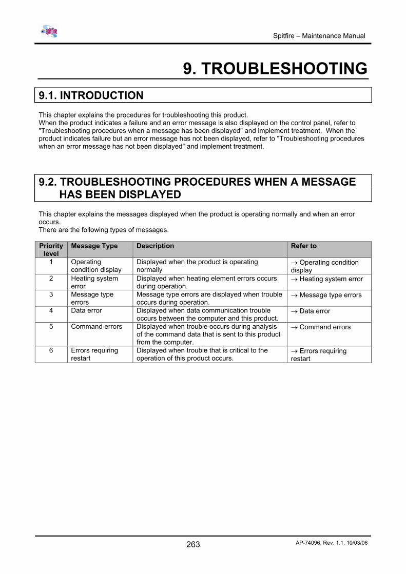
9. TROUBLESHOOTING 9.1. INTRODUCTION This chapter explains the procedures for troubleshooting this product. When the product indicates a failure and an error message is also displayed on the control panel, refer to "Troubleshooting procedures when a message has been displayed" and implement treatment. When the product indicates failure but an error message has not been displayed, refer to "Troubleshooting procedures when an error message has not been displayed" and implement treatment.
9.2. TROUBLESHOOTING PROCEDURES WHEN A MESSAGE HAS BEEN DISPLAYED
This chapter explains the messages displayed when the product is operating normally and when an error occurs. There are the following types of messages. Priority
level Message Type Description Refer to
1 Operating condition display
Displayed when the product is operating normally
→ Operating condition display
2 Heating system error
Displayed when heating element errors occurs during operation.
→ Heating system error
3 Message type errors
Message type errors are displayed when trouble occurs during operation.
→ Message type errors
4 Data error Displayed when data communication trouble occurs between the computer and this product.
→ Data error
5 Command errors Displayed when trouble occurs during analysis of the command data that is sent to this product from the computer.
→ Command errors
6 Errors requiring restart
Displayed when trouble that is critical to the operation of this product occurs.
→ Errors requiring restart
Spitfire – Maintenance Manual
264 AP-74096, Rev. 1.1, 10/03/06
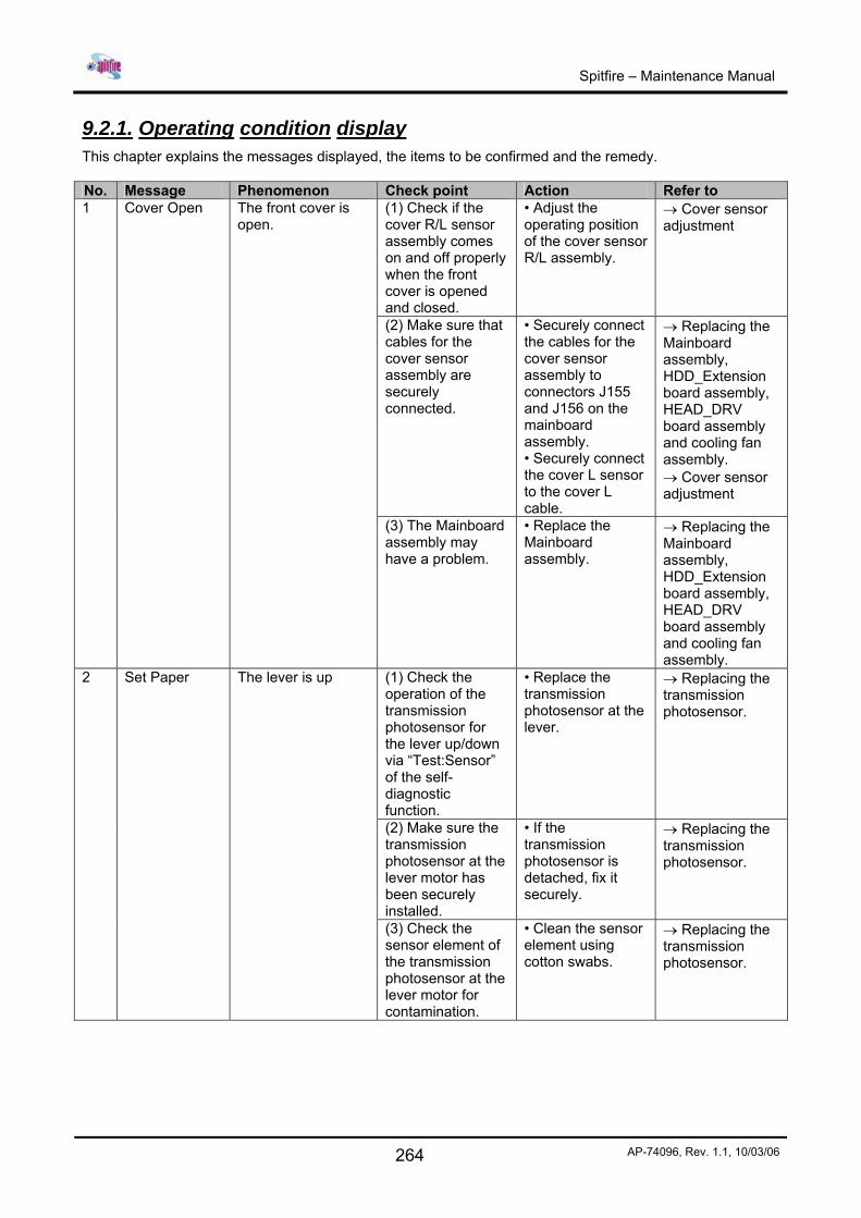
9.2.1. Operating condition display This chapter explains the messages displayed, the items to be confirmed and the remedy. No. Message Phenomenon Check point Action Refer to
(1) Check if the cover R/L sensor assembly comes on and off properly when the front cover is opened and closed.
• Adjust the operating position of the cover sensor R/L assembly.
→ Cover sensor adjustment
(2) Make sure that cables for the cover sensor assembly are securely connected.
• Securely connect the cables for the cover sensor assembly to connectors J155 and J156 on the mainboard assembly. • Securely connect the cover L sensor to the cover L cable.
→ Replacing the Mainboard assembly, HDD_Extension board assembly, HEAD_DRV board assembly and cooling fan assembly. → Cover sensor adjustment
1 Cover Open The front cover is open.
(3) The Mainboard assembly may have a problem.
• Replace the Mainboard assembly.
→ Replacing the Mainboard assembly, HDD_Extension board assembly, HEAD_DRV board assembly and cooling fan assembly.
(1) Check the operation of the transmission photosensor for the lever up/down via “Test:Sensor” of the self-diagnostic function.
• Replace the transmission photosensor at the lever.
→ Replacing the transmission photosensor.
(2) Make sure the transmission photosensor at the lever motor has been securely installed.
• If the transmission photosensor is detached, fix it securely.
→ Replacing the transmission photosensor.
2 Set Paper The lever is up
(3) Check the sensor element of the transmission photosensor at the lever motor for contamination.
• Clean the sensor element using cotton swabs.
→ Replacing the transmission photosensor.
Spitfire – Maintenance Manual
265 AP-74096, Rev. 1.1, 10/03/06
(4) Make sure the transmission photosensor cables at the lever motor have been securely installed.
• Securely connect the transmission photosensor cables to Mainboard assembly connectors J123 and J124.
→ Replacing the Mainboard assembly, HDD_Extension board assembly, HEAD_DRV board assembly and cooling fan assembly.
(5) Check the operation of the foot lever via “Test:Sensor” of the self-diagnostic function.
• Replace the foot switch
→ Refer to the User’s Guide
(6) The Mainboard assembly may have a problem.
• Replace the Mainboard assembly.
→ Replacing the Mainboard assembly, HDD_Extension board assembly, HEAD_DRV board assembly and cooling fan assembly.
(1) Check he operation of the “Test:Sensor” via the self-diagnostic function.
• If OFF is displayed when he paper is setup, replace he P_REAR sensor assembly.
→ Replacing the P_REAR_R sensor assembly and P_REAR_L sensor assembly.
(2) Make sure P_REAR sensor assembly cables underneath the paper guide R are securely connected.
• Securely connect the cables to Mainboard assembly connectors J128 and J129.
→ Replacing the Mainboard assembly, HDD_Extension board assembly, HEAD_DRV board assembly and cooling fan assembly.
(3) The P_REAR sensor assembly may be damaged.
• Replace the P_REAR sensor assembly.
→ Replacing the P_REAR_R sensor assembly and P_REAR_L sensor assembly.
3 Paper End The paper is not setup
(4) The Mainboard assembly may have a problem.
• Replace the Mainboard assembly.
→ Replacing the Mainboard assembly, HDD_Extension board assembly, HEAD_DRV board assembly and cooling fan assembly.
Spitfire – Maintenance Manual
266 AP-74096, Rev. 1.1, 10/03/06
9.2.2. Message type errors The following explains the messages, items to be confirmed and remedies to take when message type errors occur while the product is operating. Message type errors are displayed when trouble occurs during operation. When message type errors occur, this product displays the following error messages on the operation panel and stops the operation. When the causes of errors are removed, message type errors are restored and the printing operation will be restarted. No. Message Phenomenon Check point Action Refer to
(1) Check the operation of the P_EDGE sensor via “Test:Sensor” of the self-diagnostic function.
• If the sensor responds to the presence of the paper, adjust the sensor volume. • If the sensor does not respond to the presence of the paper, replace the P_EDGE sensor assembly
→ Media sensor sensitivity adjustment → Replacing the P_EDGE sensor assembly.
(2) Make sure the P_EDGE sensor assembly connector at the cursor is securely connected.
• Securely connect it to CR board assembly connector J234.
→ Replacing the Mainboard assembly, HDD_Extension board assembly, HEAD_DRV board assembly and cooling fan assembly.
(3) Make sure the R_REAR sensor assembly cables underneath paper guide R are securely connected.
• Securely connect the cables to Mainboard assembly connectors J128 and J129.
→ Replacing the Mainboard assembly, HDD_Extension board assembly, HEAD_DRV board assembly and cooling fan assembly.
(4) Check the CR tape power cables for skewed insertion.
• Redo the connections of the following connectors : • CR board : J201 – J216 • Mainboard : J137 – J152
→ Replacing the Mainboard assembly, HDD_Extension board assembly, HEAD_DRV board assembly and cooling fan assembly.
(5) The CR tape power cables may be damaged.
• Replace the CR tape power cables.
→ Replacing the steel bearer, tube guide, CR tape power cable and ink tube.
1 Undefined paper
The printer failed to detect the media.
(6) The CR board assembly may be damaged.
• Replace the CR board assembly.
→ Replacing the CR board assembly.
Spitfire – Maintenance Manual
267 AP-74096, Rev. 1.1, 10/03/06
(7) The Mainboard assembly may be damaged.
• Replace the Mainboard assembly.
→ Replacing the Mainboard assembly, HDD_Extension board assembly, HEAD_DRV board assembly and cooling fan assembly.
2 Paper Slant The paper is fed askew.
(1) Reset the paper and check if the condition recurs.
• If this is caused by incorrect paper setup, explain the correct paper setup procedure.
-
(1) Check the cutter grooves for accumulated paper dust and slip.
• Remove the accumulated paper dust along the direction of the grooves.
→ Please refer to the User’s Guide.
(2) has the cutter cap securely been installed?
• Reset the cutter cap securely
→ Please refer to the User’s Guide.
(3) Check the cutter’s up and down sliding operation.
• If it does not rise : Go to step (4) • If it rises : Go to step (5)
3 Paper Cut Error
Even though cutting operation was performed, the paper was not completely cut and removed.
(4) Check if the cutter drops to the bottom end under its own weight when the cutter has been installed without the cutter spring.
•If it drops : The cutter spring may have a problem. Replace the cutter spring while referring to the unfolded view. • If it does not drop : The cutter may have a problem. Replace the cutter. If the cutter does not drop after replaced, replace the cutter holder.
→ Replacing the cutter holder, cutter spring, cutter cap, solenoid assembly and solenoid spring.
Spitfire – Maintenance Manual
268 AP-74096, Rev. 1.1, 10/03/06
(5) Check the up and down operation of the solenoid via “Life/Cutter” of the self-diagnostic function. a) The solenoid moves up and down : Check the cutter’s down position relative to the cutter groove. b) It does not move up and down.
OK : The cutter’s service life is reached or it is damaged. Replace the cutter. NG : Adjust the position of the cutter holder. • The connectors may have poor contacts. Check the connections of the following connectors : CR board : J235 CR board : J201 – J216 Mainboard : J137 – J152
→ Please refer to the User’s Guide → Cutter adjustment → Replacing the CR board assembly. → Replacing the Mainboard assembly, HDD_Extension board assembly, HEAD_DRV board assembly and cooling fan assembly.
(6) Open CR cable, faulty solenoid assembly, faulty board assembly, etc., may be the cause.
•Replace the CR tape power cables. • Replace the solenoid assembly • Replace the CR board assembly • Replace the Mainboard assembly.
→ Replacing the steel bearer, tube guide, CR tape power cable and ink tube. → Replacing the cutter holder, cutter spring, cutter cap, solenoid assembly and solenoid spring → Replacing the CR board assembly → Replacing the Mainboard assembly, HDD_Extension board assembly, HEAD_DRV board assembly and cooling fan assembly.
4 End of Roll Displayed when the end of the roll paper is detected during the use of roll paper. This is released when the lever has
(1) Check if the message is still displayed after turning the power off and then back on again.
If the message is displayed : go to step (2)
Spitfire – Maintenance Manual
269 AP-74096, Rev. 1.1, 10/03/06
(2) Check the P_REAR sensor assembly for the contact condition.
•Redo the connections of Mainboard assembly connectors J128 and J129. If the paper is not initialized, the sensor may be damaged. • Replace the P_REAR sensor assembly.
→ Replacing the Mainboard assembly, HDD_Extension board assembly, HEAD_DRV board assembly and cooling fan assembly. → Replacing the P_REAR_R sensor assembly and P_REAR_L sensor assembly.
been set to the up position.
(3) The Mainboard may be damaged.
• Replace the Mainboard assembly.
→ Replacing the Mainboard assembly, HDD_Extension board assembly, HEAD_DRV board assembly and cooling fan assembly.
(1) Check the ink end via “Test: Sensor” of the self-diagnostic function.
• Operate the lever at the end detecting element of the ink sensor assembly to check if the ink end indication changes. (At this time, the sensor for detecting the presence of cartridges is set to Yes.) If there is no response, replace the ink sensor assembly.
→ Sensor menu → Replacing the I/H (ink holder) assembly
5 6
[ ] Near End [ ] Ink End
The remaining amount of ink is low. Printing is still possible. There is no more ink left. Printing in progress is interrupted immediately.
(2) Check the ink sensor connector for the contact conditions.
• Redo the connections of the following connectors. • Junction board : J401 – J418 • Mainboard : J133 – J134
→ Replacing the Junction board assembly.
7 Not Original Ink
(1) Check the ink end ID via “Test: Sensor” of the self-diagnostic function. (This is limited to when smart chips are set.)
• If the type of the installed cartridge does not match the displayed type, the ink ID sensor may be damaged.
→ Sensor menu
Spitfire – Maintenance Manual
270 AP-74096, Rev. 1.1, 10/03/06
(2) Check the ink ID sensor connector for the contact conditions.
• Redo the connections of the following connectors : • Junction board : J401 – J418 • Mainboard : J133 – J134
→ Replacing the JUNCTION board assembly.
(3) The Mainboard may be damaged.
• Replace the Mainboard assembly.
→ Replacing the Mainboard assembly, HDD_Extension board assembly, HEAD_DRV board assembly and cooling fan assembly.
(1) Check if the message is still displayed after turning the power off and then back on again.
• When a message is displayed : Go to step (2)
-
(2) The amount of waste ink inside the tank reached the specified level.
• Dispose of the waste ink in the waste bottle.
-
8 Warning Waste INK Tank
The waste tank will soon be full.
(3) If initialization does take effect when the waste ink is disposed of and waste ink history is initialized, the Mainboard may be damaged.
• Replace the Mainboard assembly.
→ Replacing the Mainboard assembly, HDD_Extension board assembly, HEAD_DRV board assembly and cooling fan assembly.
(1) Check if the message is still displayed after turning the power off and then back on again.
• When a message is displayed : Go to step (2)
-
(2) The number of times the ink tube was used reached the maximum allowable times.
• Replace the ink tube. • Initializing CR motor history.
→ Replacing the steel bearer, tube guide, CR tape power cable and ink tube.
9 Warning Waste INK Tank
The service life of the ink tube will soon be reached.
(3) If initialization does take effect when the CR motor history is initialized after the ink tube is replaced, the Mainboard may be damaged.
• Replace the Mainboard assembly.
→ Replacing the Mainboard assembly, HDD_Extension board assembly, HEAD_DRV board assembly and cooling fan assembly.
Spitfire – Maintenance Manual
271 AP-74096, Rev. 1.1, 10/03/06
(1) Check if the message is still displayed after turning the power off and then back on again.
• When a message is displayed : refer to step (2)
(2) The number of times the print head was used reached the maximum allowable times.
• Replace the print head assembly. • Initialize the head unit.
→ Replacing the print head assembly and head tape power cable. → Counter initialization menu.
10 (Warning Head Life)
The service life of the print head will soon be reached.
(3) If initialization does not take effect when the head unit is initialized, the Mainboard assembly may be damaged.
• Replace the Mainboard assembly.
→ Replacing the Mainboard assembly, HDD_Extension board assembly, HEAD_DRV board assembly and cooling fan assembly
(1) Check the connections of connectors.
• Redo the connections of the following connectors. • Mainboard : J102 • power source board (small) assembly : CN51 – CN52
(2) The HDD_MOTHER board assembly may be damaged.
• Replace the ink tube. • Initializing CR motor history.
(3) Hard disk may be damaged.
• Replace the hard disks.
11 Hard disk status connect error
There is a problem in the hard disk connections.
(4) The Mainboard assembly may be damaged.
• Replace the Mainboard assembly.
→ Replacing the Mainboard assembly, HDD_Extension board assembly, HEAD_DRV board assembly and cooling fan assembly. → Replacing the power source board assembly.
(1) The PCI_LINUX board assembly may be damaged.
• Replace the PCI_LINUX board assembly.
12 Network initialize error
There is a problem in the network board.
(2) The Mainboard assembly may be damaged.
• Replace the Mainboard assembly.
→ Replacing the Mainboard assembly, HDD_Extension board assembly, HEAD_DRV board assembly and cooling fan assembly.
(1) Check if the waste bottle has been installed.
• Install the waste bottle correctly.
- 13 Waste ink tank sts. No
The waste tank is not installed.
(2) Check the operation of the waste box sensor assembly via “Sensor/Waste Bin” of the self-diagnostic function.
• Replace the waste box sensor assembly.
-
Spitfire – Maintenance Manual
272 AP-74096, Rev. 1.1, 10/03/06
(3) Check the connections of the connectors.
•Check if the waste box sensor connectors are connected to the rear side cap R. • Redo the connections of the following connectors. • Mainboard : J120
→ Replacing the Mainboard assembly, HDD_Extension board assembly, HEAD_DRV board assembly and cooling fan assembly.
(4) The Mainboard assembly may be damaged.
• Replace the Mainboard assembly.
→ Replacing the Mainboard assembly, HDD_Extension board assembly, HEAD_DRV board assembly and cooling fan assembly.
Notes :
The number between brackets [ ] on the error display indicates the cartridge number.
Spitfire – Maintenance Manual
273 AP-74096, Rev. 1.1, 10/03/06
9.2.3. Heating system error The following explains the messages, items to be confirmed and remedies to take when errors handling heating system occur while the product is operating. Heating system errors are displayed when communication trouble occurs between the heater strips and this product. If heating system error occurs, the following error messages are displayed and the printer stops. Solve the problem to delete the error message and restart the printer. No Message Check point Action 1 AC not present AC connector. Check AC connector 2 Error sensors A Sensors A Check if the sensors are connected properly. 3 Error sensor A Sensor A Check if the sensors are connected properly. 4 Conn. err. Left A Sensor A Check if the left sensor is connected properly. 5 Conn. err. Right A Sensor A Check if the right sensor is connected properly. 6 Error sensors D1 Sensors D1 Check if the sensors are connected properly. 7 Error sensor D1 Sensor D1 Check if the sensors are connected properly. 8 Conn. err. Left D1 Sensor D1 Check if the left sensor is connected properly. 9 Conn. err. Right D1 Sensor D1 Check if the right sensor is connected properly. 10 Error sensors D2 Sensors D2 Check if the sensors are connected properly. 11 Error sensor D2 Sensor D2 Check if the sensors are connected properly. 12 Conn. err. Left D2 Sensor D2 Check if the left sensor is connected properly. 13 Conn. err. Right D2 Sensor D2 Check if the right sensor is connected properly. 14 Couldn't reach temp Heater strip After 10 minutes, temperature is not reached. Check
the heater strips. 15 Err: Temp > 85°C! Heater strip Temperature comes higher then the limit. Check the
heater strips. 16 Connection err. A Rear Heater (A) Check the connector of the rear heater. 17 Connection err. D1 Dryer (D1) Check the connector of the front heater (D1). 18 Connection err. D2 Dryer (D2) Check the connector of the front heater (D2). 19 Error sensor B1 Fixer (B1) Check the sensor of the fixer 1 (B1). 20 Error sensor C Post fixer (C) Check the sensor of the fixer (C). 21 Connection err. B1 Fixer (B1) Check the connector of the fixer 1 (B1). 22 Connection err. C Post fixer (C) Check the connector of the post fixer (c). 23 Error sensor B2 Fixer (B2) Check the sensor of the fixer 2 (B2) 24 Connection err. B2 Fixer (B2) Check the connector of the fixer 2 (B2). 25 Error D group Heaters D Temperature difference higher than 15°C between
the sensors of the D heaters. 26 Error A group Heaters A Temperature difference higher then 15°C between
the sensors of the A heaters. 27 Error B group Heaters B Temperature difference higher then 15°C between
the sensors of the B heaters.
Important : Before checking the connectors, please power off the unit and remove the power cable.
Notes :
Check if the connectors are properly connected to the power board. Check if the sensors are connected onto the right connector.
Spitfire – Maintenance Manual
274 AP-74096, Rev. 1.1, 10/03/06
9.2.4. Data error The following explains the messages, items to be confirmed and remedies to take when data errors occur while the product is operating. Data errors are displayed when data communication trouble occurs between the computer and this product. If data error display occurs, the following error messages are displayed and the printer stops. Solve the problem to delete the error message and restart the printer. No. Message Phenomenon Check point Action Refer to 1 I 15-1 error
command [ ] Online frame error
2 I 15-2 error command [ ]
Overrun error
3 I 15-3 error command [ ]
Online parity error
4 I 15-4 error command [ ]
Sum check error
5 I 15-5 error command [ ]
ESC parameter
6 I 15-6 error command [ ]
Undefined ESC
7 I 15-7 error command [ ]
Incorrect letters ESC
8 I 15-8 error command [ ]
Numeral character ESC
9 I 15-9 error command [ ]
Parameter error ESC
10 I 15-10 error command [ ]
Buffer overflow
(1) Check the printing data for contents that may be judges as an error. (2) Mainboard assembly may be defective?
• Try a different drive for the application. • Replace Mainboard assembly
→ Replacing the Mainboard assembly, HDD_Extension board assembly, HEAD_DRV board assembly and cooling fan assembly.
Notes :
The command codes for errors may be indicated between brackets [ ].
Spitfire – Maintenance Manual
275 AP-74096, Rev. 1.1, 10/03/06
9.2.5. Command errors The following explains the messages, items to be confirmed and remedies to take when command errors occur while the product is operating. Command errors are displayed when trouble occurs during analysis of the command data that is sent to this product from the computer. If a command error occurs, the following error messages are displayed and the printer stops. Solve the problem to delete the error message and restart the printer. No. Message Phenomenon Check point Action Refer to 1 MH01 error
command [ ] Undefined ESC: A command that has not been defined in command modes was analyzed.
2 MH02 error command [ ]
Parameter error : Number of parameters following command is incorrect.
3 MHO3 error command [ ]
Numeric error : Number of parameters following command is incorrect.
4 MH04 error command [ ]
Undefined letter set: Letter sets that should not exist (do exist).
5 MH05 error command [ ]
Buffer overflow: Polygon buffer or downloadable character buffer overflows.
(1) Check the printing data for contents that may be judged as an error. (2) The Mainboard assembly may have a problem.
• Try a different drive for the application • Replace Mainboard assembly
→ Replacing the Mainboard assembly, HDD_Extension board assembly, HEAD_DRV board assembly and cooling fan assembly.
Notes :
The command codes for errors may be indicated between brackets [ ].
For the settings on a computer, refer to the computer's operation manual.
Spitfire – Maintenance Manual
276 AP-74096, Rev. 1.1, 10/03/06
9.2.6. Errors requiring restart The following explains the messages, items to be confirmed and remedies to take when errors requiring restart occur while the product is operating. Errors requiring restart are displayed when trouble critical to the operation of this product occurs.
Foreign material disturbing the printer operation has been loaded in the printer. An electrical circuit (such as board, motor or sensor) failure has occurred. An error on control program of the printer has occurred. When errors requiring restart occur.
The product stops operation after the following actions take place. 1. The power supply to the operation has been automatically shut-off. 2. All lamps on the operation panel flash and the buzzer sounds intermittently. 3. Error messages are displayed on the operation panel. If an error requiring a restart has occurred, solve the problems to restart the printer and delete the error. (1) CPU system critical errors No. Message Phenomenon Check point Action Refer to 1 E 001 error
DRAM Standard DRAM error : Abnormal condition in standard memory mounted on Mainboard assembly
(1) Mainboard assembly may be defective.
• Replace Mainboard assembly
→ Replacing the Mainboard assembly, HDD_Extension board assembly, HEAD_DRV board assembly and cooling fan assembly.
(1) If foreign material is present in the slot (J103) of the extended memory, errors may result.
• Remove dust using a tool such as air duster, then reinstall the memory.
(2) Install known good optional memory (the capacity must be equal to the one in the user’s unit) then check the equipped memory capacity via “Test:Ram Capacity” of the self-diagnostic function.
• Replace memory.
2 E 002 error Opt. DRAM
Option DRAM error : Abnormal condition in optional memory mounted on Mainboard assembly
(3) Mainboard assembly may be defective.
• Replace Mainboard assembly
→ Replacing the Mainboard assembly, HDD_Extension board assembly, HEAD_DRV board assembly and cooling fan assembly.
Spitfire – Maintenance Manual
277 AP-74096, Rev. 1.1, 10/03/06
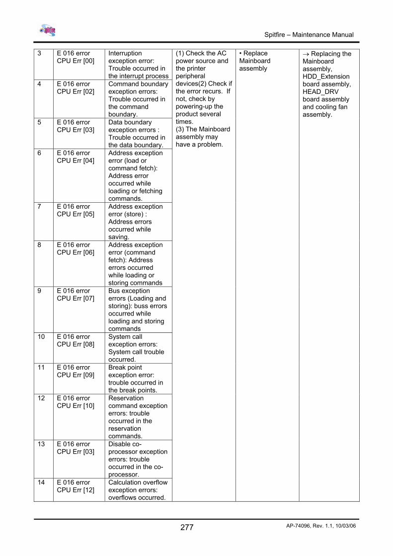
3 E 016 error CPU Err [00]
Interruption exception error: Trouble occurred in the interrupt process
4 E 016 error CPU Err [02]
Command boundary exception errors: Trouble occurred in the command boundary.
5 E 016 error CPU Err [03]
Data boundary exception errors : Trouble occurred in the data boundary.
6 E 016 error CPU Err [04]
Address exception error (load or command fetch): Address error occurred while loading or fetching commands.
7 E 016 error CPU Err [05]
Address exception error (store) : Address errors occurred while saving.
8 E 016 error CPU Err [06]
Address exception error (command fetch): Address errors occurred while loading or storing commands
9 E 016 error CPU Err [07]
Bus exception errors (Loading and storing): buss errors occurred while loading and storing commands
10 E 016 error CPU Err [08]
System call exception errors: System call trouble occurred.
11 E 016 error CPU Err [09]
Break point exception error: trouble occurred in the break points.
12 E 016 error CPU Err [10]
Reservation command exception errors: trouble occurred in the reservation commands.
13 E 016 error CPU Err [03]
Disable co-processor exception errors: trouble occurred in the co-processor.
14 E 016 error CPU Err [12]
Calculation overflow exception errors: overflows occurred.
(1) Check the AC power source and the printer peripheral devices(2) Check if the error recurs. If not, check by powering-up the product several times. (3) The Mainboard assembly may have a problem.
• Replace Mainboard assembly
→ Replacing the Mainboard assembly, HDD_Extension board assembly, HEAD_DRV board assembly and cooling fan assembly.
Spitfire – Maintenance Manual
278 AP-74096, Rev. 1.1, 10/03/06
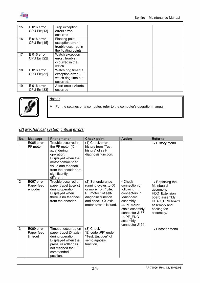
15 E 016 error CPU Err [13]
Trap exception errors : trap occurred
16 E 016 error CPU Err [15]
Floating point exception error : trouble occurred in the floating points
17 E 016 error CPU Err [22]
Watch exception error : trouble occurred in the watch.
18 E 016 error CPU Err [32]
Watch dog timeout exception error : watch dog time out occurred.
19 E 016 error CPU Err [33]
Abort error : Aborts occurred
Notes :
For the settings on a computer, refer to the computer's operation manual.
(2) Mechanical system critical errors No. Message Phenomenon Check point Action Refer to 1 E065 error
PF motor Trouble occurred in the PF motor (X-axis) during operation. Displayed when the motor commended value and feedback from the encoder are significantly different.
(1) Check error history from “Test: history” of self-diagnosis function.
→ History menu
2 E067 error Paper feed encoder
Trouble occurred on paper travel (x-axis) during operation. Displayed when there is no feedback from the encoder.
(2) Set endurance running cycles to 50 or more from “Life: PF motor “ of self-diagnosis function and check if X-axis motor error is issued.
• Check connection of following connectors in Mainboard assembly: → PF motor cable assembly connector J157 → PF_ENC assembly connector J154
→ Replacing the Mainboard assembly, HDD_Extension board assembly, HEAD_DRV board assembly and cooling fan assembly.
3 E069 error Paper feed timeout
Timeout occurred on paper travel (X-axis) during operation. Displayed when the pressure roller has not reached the commanded position.
(3) Check “Encoder:PF” under “Test: Encoder” of self-diagnosis function.
→ Encoder Menu
Spitfire – Maintenance Manual
279 AP-74096, Rev. 1.1, 10/03/06
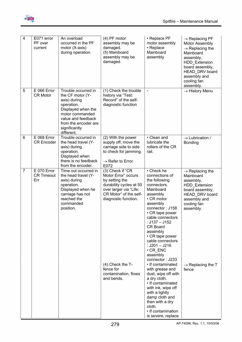
4 E071 error
PF over current
An overload occurred in the PF motor (X-axis) during operation.
(4) PF motor assembly may be damaged. (5) Mainboard assembly may be damaged.
• Replace PF motor assembly • Replace Mainboard assembly
→ Replacing PF Motor Assembly → Replacing the Mainboard assembly, HDD_Extension board assembly, HEAD_DRV board assembly and cooling fan assembly.
5 E 066 Error CR Motor
Trouble occurred in the CF motor (Y-axis) during operation. Displayed when the motor commanded value and feedback from the encoder are significantly different.
(1) Check the trouble history via “Test: Record” of the self-diagnostic function
- → History Menu
6 E 068 Error CR Encoder
Trouble occurred in the head travel (Y-axis) during operation. Displayed when there is no feedback from the encoder.
(2) With the power supply off, move the carriage side to side to check for jamming. → Refer to Error E072
• Clean and lubricate the rollers of the CR rail.
→ Lubrication / Bonding
(3) Check if “CR Motor Error” occurs by setting the durability cycles at 50 over larger via “Life: CR Motor” of the self-diagnostic function.
• Check he connections of the following connectors. Mainboard
assembly • CR motor assembly connector : J158 • CR tape power cable connectors : J137 – J152 CR Board assembly • CR tape power cable connectors : J201 – J216 • CR_ENC assembly connector : J233
→ Replacing the Mainboard
assembly, HDD_Extension board assembly, HEAD_DRV board assembly and cooling fan assembly.
7 E 070 Error CR Timeout Err
Time out occurred in the head travel (Y-axis) during operation. Displayed when he carriage has not reached the commanded position.
(4) Check the T-fence for contamination, flows and bends.
• If contaminated with grease and dust, wipe off with a dry cloth. • If contaminated with ink, wipe off with a lightly damp cloth and then with a dry cloth. • If contamination is severe, replace
→ Replacing the T fence
Spitfire – Maintenance Manual
280 AP-74096, Rev. 1.1, 10/03/06
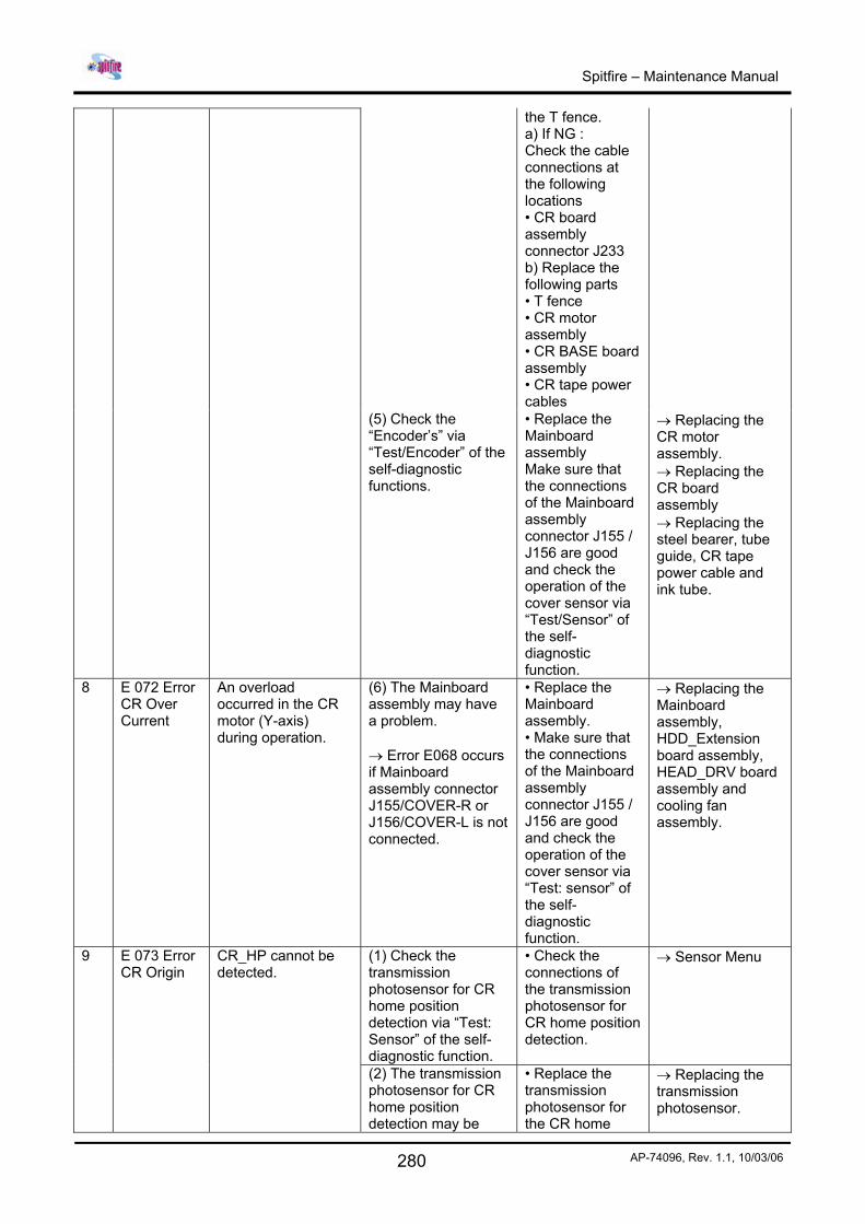
the T fence. a) If NG : Check the cable connections at the following locations • CR board assembly connector J233 b) Replace the following parts • T fence • CR motor assembly • CR BASE board assembly • CR tape power cables
(5) Check the “Encoder’s” via “Test/Encoder” of the self-diagnostic functions.
• Replace the Mainboard assembly Make sure that the connections of the Mainboard assembly connector J155 / J156 are good and check the operation of the cover sensor via “Test/Sensor” of the self-diagnostic function.
→ Replacing the CR motor assembly. → Replacing the CR board assembly → Replacing the steel bearer, tube guide, CR tape power cable and ink tube.
8 E 072 Error CR Over Current
An overload occurred in the CR motor (Y-axis) during operation.
(6) The Mainboard
assembly may have a problem. → Error E068 occurs if Mainboard assembly connector J155/COVER-R or J156/COVER-L is not connected.
• Replace the Mainboard
assembly. • Make sure that the connections of the Mainboard assembly connector J155 / J156 are good and check the operation of the cover sensor via “Test: sensor” of the self-diagnostic function.
→ Replacing the Mainboard
assembly, HDD_Extension board assembly, HEAD_DRV board assembly and cooling fan assembly.
(1) Check the transmission photosensor for CR home position detection via “Test: Sensor” of the self-diagnostic function.
• Check the connections of the transmission photosensor for CR home position detection.
→ Sensor Menu 9 E 073 Error CR Origin
CR_HP cannot be detected.
(2) The transmission photosensor for CR home position detection may be
• Replace the transmission photosensor for the CR home
→ Replacing the transmission photosensor.
Spitfire – Maintenance Manual
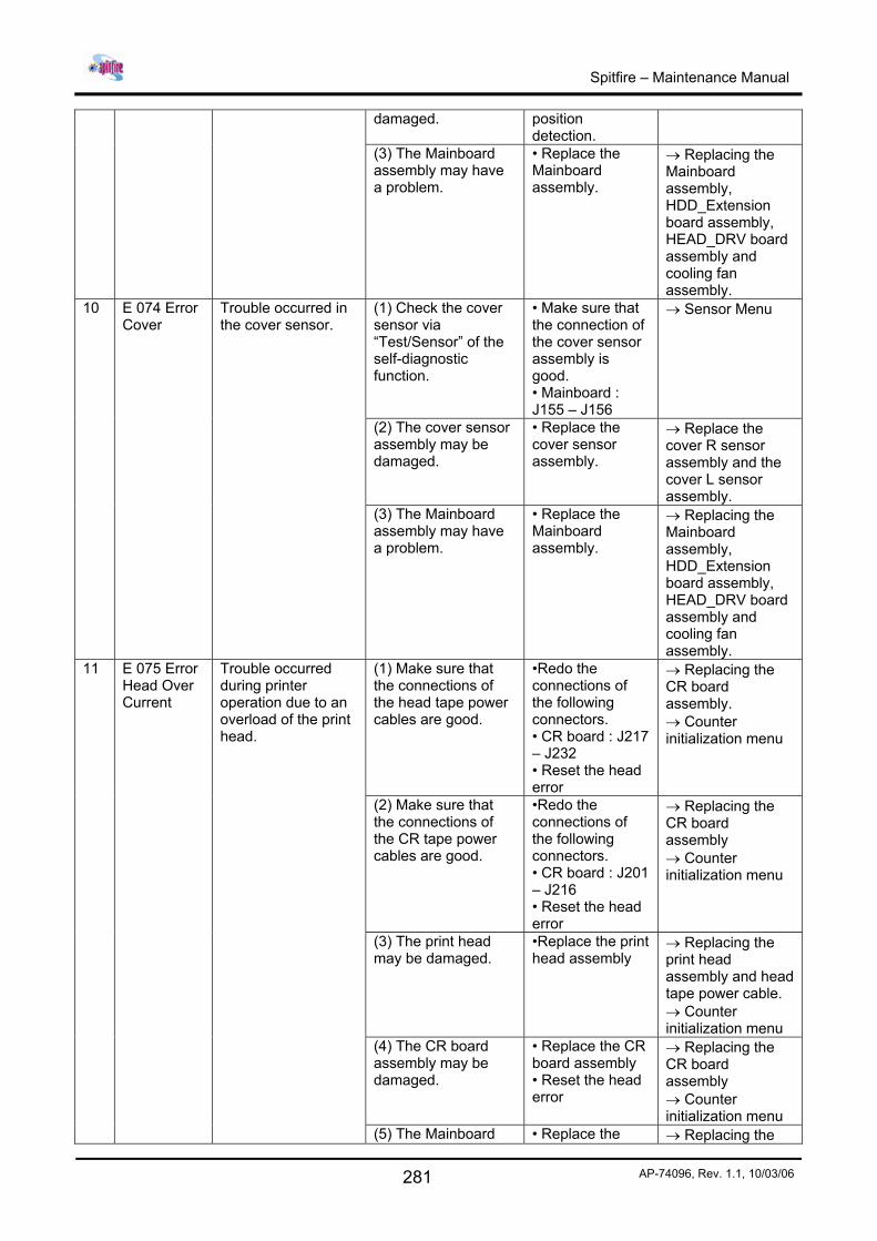
281 AP-74096, Rev. 1.1, 10/03/06
damaged. position detection.
(3) The Mainboard assembly may have a problem.
• Replace the Mainboard assembly.
→ Replacing the Mainboard assembly, HDD_Extension board assembly, HEAD_DRV board assembly and cooling fan assembly.
(1) Check the cover sensor via “Test/Sensor” of the self-diagnostic function.
• Make sure that the connection of the cover sensor assembly is good. • Mainboard : J155 – J156
→ Sensor Menu
(2) The cover sensor assembly may be damaged.
• Replace the cover sensor assembly.
→ Replace the cover R sensor assembly and the cover L sensor assembly.
10 E 074 Error Cover
Trouble occurred in the cover sensor.
(3) The Mainboard assembly may have a problem.
• Replace the Mainboard assembly.
→ Replacing the Mainboard assembly, HDD_Extension board assembly, HEAD_DRV board assembly and cooling fan assembly.
(1) Make sure that the connections of the head tape power cables are good.
•Redo the connections of the following connectors. • CR board : J217 – J232 • Reset the head error
→ Replacing the CR board assembly. → Counter initialization menu
(2) Make sure that the connections of the CR tape power cables are good.
•Redo the connections of the following connectors. • CR board : J201 – J216 • Reset the head error
→ Replacing the CR board assembly → Counter initialization menu
(3) The print head may be damaged.
•Replace the print head assembly
→ Replacing the print head assembly and head tape power cable. → Counter initialization menu
(4) The CR board assembly may be damaged.
• Replace the CR board assembly • Reset the head error
→ Replacing the CR board assembly → Counter initialization menu
11 E 075 Error Head Over Current
Trouble occurred during printer operation due to an overload of the print head.
(5) The Mainboard • Replace the → Replacing the
Spitfire – Maintenance Manual
282 AP-74096, Rev. 1.1, 10/03/06
assembly may have a problem
Mainboard assembly • Reset the head error
Mainboard assembly, HDD_Extension board assembly, HEAD_DRV board assembly and cooling fan assembly. → Counter initialization menu
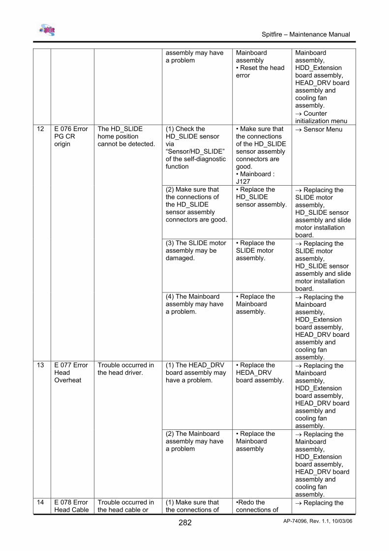
(1) Check the HD_SLIDE sensor via “Sensor/HD_SLIDE” of the self-diagnostic function
• Make sure that the connections of the HD_SLIDE sensor assembly connectors are good. • Mainboard : J127
→ Sensor Menu
(2) Make sure that the connections of the HD_SLIDE sensor assembly connectors are good.
• Replace the HD_SLIDE sensor assembly.
→ Replacing the SLIDE motor assembly, HD_SLIDE sensor assembly and slide motor installation board.
(3) The SLIDE motor assembly may be damaged.
• Replace the SLIDE motor assembly.
→ Replacing the SLIDE motor assembly, HD_SLIDE sensor assembly and slide motor installation board.
12 E 076 Error PG CR origin
The HD_SLIDE home position cannot be detected.
(4) The Mainboard assembly may have a problem.
• Replace the Mainboard assembly.
→ Replacing the Mainboard assembly, HDD_Extension board assembly, HEAD_DRV board assembly and cooling fan assembly.
(1) The HEAD_DRV board assembly may have a problem.
• Replace the HEDA_DRV board assembly.
→ Replacing the Mainboard assembly, HDD_Extension board assembly, HEAD_DRV board assembly and cooling fan assembly.
13 E 077 Error Head Overheat
Trouble occurred in the head driver.
(2) The Mainboard assembly may have a problem
• Replace the Mainboard assembly
→ Replacing the Mainboard assembly, HDD_Extension board assembly, HEAD_DRV board assembly and cooling fan assembly.
14 E 078 Error Head Cable
Trouble occurred in the head cable or
(1) Make sure that the connections of
•Redo the connections of
→ Replacing the
Spitfire – Maintenance Manual
283 AP-74096, Rev. 1.1, 10/03/06
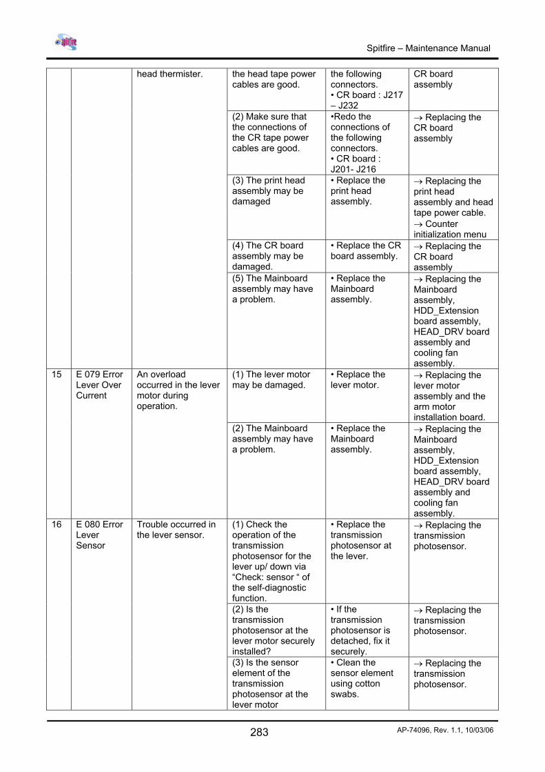
the head tape power cables are good.
the following connectors. • CR board : J217 – J232
CR board assembly
(2) Make sure that the connections of the CR tape power cables are good.
•Redo the connections of the following connectors. • CR board : J201- J216
→ Replacing the CR board assembly
(3) The print head assembly may be damaged
• Replace the print head assembly.
→ Replacing the print head assembly and head tape power cable. → Counter initialization menu
(4) The CR board assembly may be damaged.
• Replace the CR board assembly.
→ Replacing the CR board assembly
head thermister.
(5) The Mainboard assembly may have a problem.
• Replace the Mainboard assembly.
→ Replacing the Mainboard assembly, HDD_Extension board assembly, HEAD_DRV board assembly and cooling fan assembly.
(1) The lever motor may be damaged.
• Replace the lever motor.
→ Replacing the lever motor assembly and the arm motor installation board.
15 E 079 Error Lever Over Current
An overload occurred in the lever motor during operation.
(2) The Mainboard assembly may have a problem.
• Replace the Mainboard assembly.
→ Replacing the Mainboard assembly, HDD_Extension board assembly, HEAD_DRV board assembly and cooling fan assembly.
(1) Check the operation of the transmission photosensor for the lever up/ down via “Check: sensor “ of the self-diagnostic function.
• Replace the transmission photosensor at the lever.
→ Replacing the transmission photosensor.
(2) Is the transmission photosensor at the lever motor securely installed?
• If the transmission photosensor is detached, fix it securely.
→ Replacing the transmission photosensor.
16 E 080 Error Lever Sensor
Trouble occurred in the lever sensor.
(3) Is the sensor element of the transmission photosensor at the lever motor
• Clean the sensor element using cotton swabs.
→ Replacing the transmission photosensor.
Spitfire – Maintenance Manual
284 AP-74096, Rev. 1.1, 10/03/06
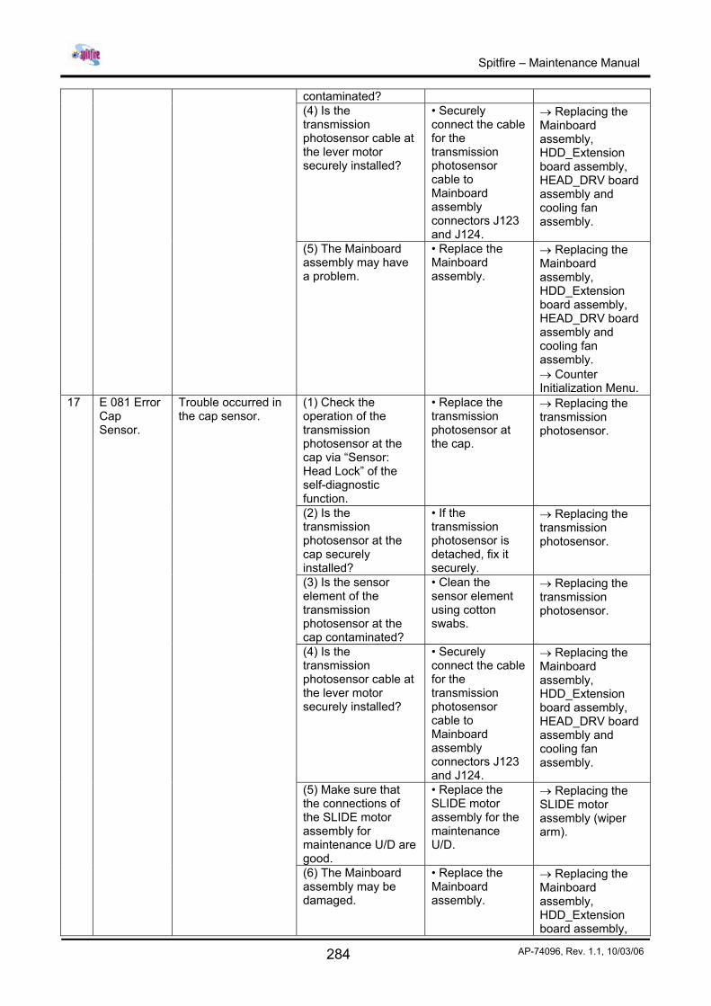
contaminated? (4) Is the transmission photosensor cable at the lever motor securely installed?
• Securely connect the cable for the transmission photosensor cable to Mainboard assembly connectors J123 and J124.
→ Replacing the Mainboard assembly, HDD_Extension board assembly, HEAD_DRV board assembly and cooling fan assembly.
(5) The Mainboard assembly may have a problem.
• Replace the Mainboard assembly.
→ Replacing the Mainboard assembly, HDD_Extension board assembly, HEAD_DRV board assembly and cooling fan assembly. → Counter Initialization Menu.
(1) Check the operation of the transmission photosensor at the cap via “Sensor: Head Lock” of the self-diagnostic function.
• Replace the transmission photosensor at the cap.
→ Replacing the transmission photosensor.
(2) Is the transmission photosensor at the cap securely installed?
• If the transmission photosensor is detached, fix it securely.
→ Replacing the transmission photosensor.
(3) Is the sensor element of the transmission photosensor at the cap contaminated?
• Clean the sensor element using cotton swabs.
→ Replacing the transmission photosensor.
(4) Is the transmission photosensor cable at the lever motor securely installed?
• Securely connect the cable for the transmission photosensor cable to Mainboard assembly connectors J123 and J124.
→ Replacing the Mainboard assembly, HDD_Extension board assembly, HEAD_DRV board assembly and cooling fan assembly.
(5) Make sure that the connections of the SLIDE motor assembly for maintenance U/D are good.
• Replace the SLIDE motor assembly for the maintenance U/D.
→ Replacing the SLIDE motor assembly (wiper arm).
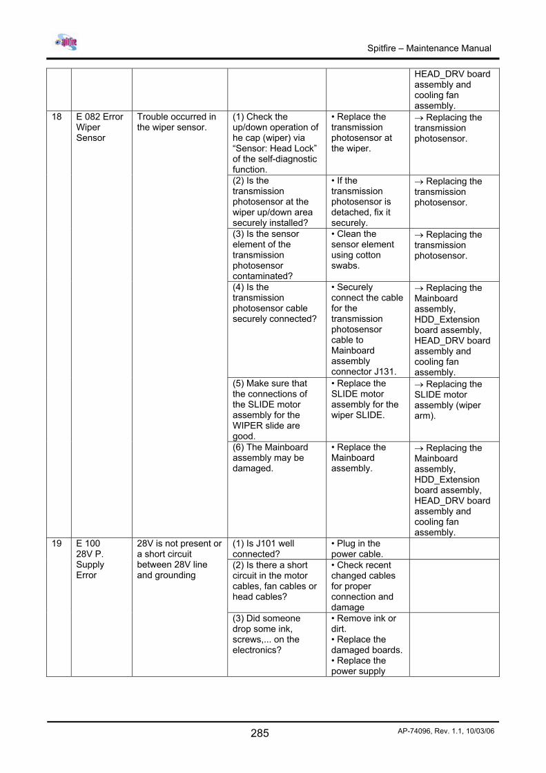
17 E 081 Error Cap Sensor.
Trouble occurred in the cap sensor.
(6) The Mainboard assembly may be damaged.
• Replace the Mainboard assembly.
→ Replacing the Mainboard assembly, HDD_Extension board assembly,
Spitfire – Maintenance Manual
285 AP-74096, Rev. 1.1, 10/03/06
HEAD_DRV board assembly and cooling fan assembly.
(1) Check the up/down operation of he cap (wiper) via “Sensor: Head Lock” of the self-diagnostic function.
• Replace the transmission photosensor at the wiper.
→ Replacing the transmission photosensor.
(2) Is the transmission photosensor at the wiper up/down area securely installed?
• If the transmission photosensor is detached, fix it securely.
→ Replacing the transmission photosensor.
(3) Is the sensor element of the transmission photosensor contaminated?
• Clean the sensor element using cotton swabs.
→ Replacing the transmission photosensor.
(4) Is the transmission photosensor cable securely connected?
• Securely connect the cable for the transmission photosensor cable to Mainboard assembly connector J131.
→ Replacing the Mainboard assembly, HDD_Extension board assembly, HEAD_DRV board assembly and cooling fan assembly.
(5) Make sure that the connections of the SLIDE motor assembly for the WIPER slide are good.
• Replace the SLIDE motor assembly for the wiper SLIDE.
→ Replacing the SLIDE motor assembly (wiper arm).
18 E 082 Error Wiper Sensor
Trouble occurred in the wiper sensor.
(6) The Mainboard assembly may be damaged.
• Replace the Mainboard assembly.
→ Replacing the Mainboard assembly, HDD_Extension board assembly, HEAD_DRV board assembly and cooling fan assembly.
(1) Is J101 well connected?
• Plug in the power cable.
(2) Is there a short circuit in the motor cables, fan cables or head cables?
• Check recent changed cables for proper connection and damage
19 E 100 28V P. Supply Error
28V is not present or a short circuit between 28V line and grounding
(3) Did someone drop some ink, screws,... on the electronics?
• Remove ink or dirt. • Replace the damaged boards. • Replace the power supply
Spitfire – Maintenance Manual
286 AP-74096, Rev. 1.1, 10/03/06
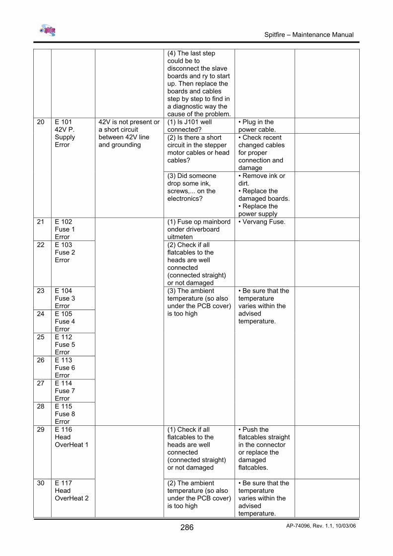
(4) The last step could be to disconnect the slave boards and ry to start up. Then replace the boards and cables step by step to find in a diagnostic way the cause of the problem.
(1) Is J101 well connected?
• Plug in the power cable.
(2) Is there a short circuit in the stepper motor cables or head cables?
• Check recent changed cables for proper connection and damage
20 E 101 42V P. Supply Error
42V is not present or a short circuit between 42V line and grounding
(3) Did someone drop some ink, screws,... on the electronics?
• Remove ink or dirt. • Replace the damaged boards. • Replace the power supply
21 E 102 Fuse 1 Error
(1) Fuse op mainbord onder driverboard uitmeten
• Vervang Fuse.
22 E 103 Fuse 2 Error
(2) Check if all flatcables to the heads are well connected (connected straight) or not damaged
23 E 104 Fuse 3 Error
24 E 105 Fuse 4 Error
25 E 112 Fuse 5 Error
26 E 113 Fuse 6 Error
27 E 114 Fuse 7 Error
28 E 115 Fuse 8 Error
(3) The ambient temperature (so also under the PCB cover) is too high
• Be sure that the temperature varies within the advised temperature.
29 E 116 Head OverHeat 1
(1) Check if all flatcables to the heads are well connected (connected straight) or not damaged
• Push the flatcables straight in the connector or replace the damaged flatcables.
30 E 117 Head OverHeat 2
(2) The ambient temperature (so also under the PCB cover) is too high
• Be sure that the temperature varies within the advised temperature.
Spitfire – Maintenance Manual
287 AP-74096, Rev. 1.1, 10/03/06
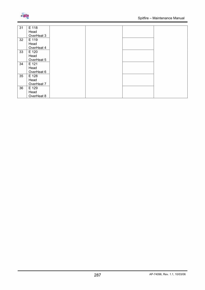
31 E 118 Head OverHeat 3
32 E 119 Head OverHeat 4
33 E 120 Head OverHeat 5
34 E 121 Head OverHeat 6
35 E 128 Head OverHeat 7
36 E 129 Head OverHeat 8
Spitfire – Maintenance Manual
288 AP-74096, Rev. 1.1, 10/03/06
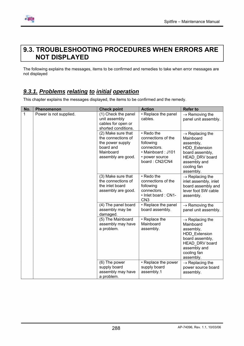
9.3. TROUBLESHOOTING PROCEDURES WHEN ERRORS ARE NOT DISPLAYED
The following explains the messages, items to be confirmed and remedies to take when error messages are not displayed
9.3.1. Problems relating to initial operation This chapter explains the messages displayed, the items to be confirmed and the remedy. No. Phenomenon Check point Action Refer to
(1) Check the panel unit assembly cables for open or shorted conditions.
• Replace the panel cables.
→ Removing the panel unit assembly.
(2) Make sure that the connections of the power supply board and Mainboard assembly are good.
• Redo the connections of the following connectors. • Mainboard : J101 • power source board : CN2/CN4
→ Replacing the Mainboard assembly, HDD_Extension board assembly, HEAD_DRV board assembly and cooling fan assembly.
(3) Make sure that the connections of the inlet board assembly are good.
• Redo the connections of the following connectors. • Inlet board : CN1-CN3
→ Replacing the inlet assembly, inlet board assembly and lever foot SW cable assembly.
(4) The panel board assembly may be damaged.
• Replace the panel board assembly.
→ Removing the panel unit assembly.
(5) The Mainboard assembly may have a problem.
• Replace the Mainboard assembly.
→ Replacing the Mainboard assembly, HDD_Extension board assembly, HEAD_DRV board assembly and cooling fan assembly.
1 Power is not supplied.
(6) The power supply board assembly may have a problem.
• Replace the power supply board assembly.1
→ Replacing the power source board assembly.
Spitfire – Maintenance Manual
289 AP-74096, Rev. 1.1, 10/03/06
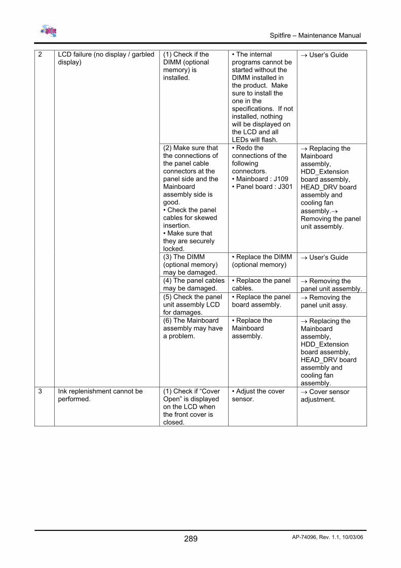
(1) Check if the DIMM (optional memory) is installed.
• The internal programs cannot be started without the DIMM installed in the product. Make sure to install the one in the specifications. If not installed, nothing will be displayed on the LCD and all LEDs will flash.
→ User’s Guide
(2) Make sure that the connections of the panel cable connectors at the panel side and the Mainboard assembly side is good. • Check the panel cables for skewed insertion. • Make sure that they are securely locked.
• Redo the connections of the following connectors. • Mainboard : J109 • Panel board : J301
→ Replacing the Mainboard assembly, HDD_Extension board assembly, HEAD_DRV board assembly and cooling fan assembly.→ Removing the panel unit assembly.
(3) The DIMM (optional memory) may be damaged.
• Replace the DIMM (optional memory)
→ User’s Guide
(4) The panel cables may be damaged.
• Replace the panel cables.
→ Removing the panel unit assembly.
(5) Check the panel unit assembly LCD for damages.
• Replace the panel board assembly.
→ Removing the panel unit assy.
2 LCD failure (no display / garbled display)
(6) The Mainboard assembly may have a problem.
• Replace the Mainboard assembly.
→ Replacing the Mainboard assembly, HDD_Extension board assembly, HEAD_DRV board assembly and cooling fan assembly.
3 Ink replenishment cannot be performed.
(1) Check if “Cover Open” is displayed on the LCD when the front cover is closed.
• Adjust the cover sensor.
→ Cover sensor adjustment.
Spitfire – Maintenance Manual
290 AP-74096, Rev. 1.1, 10/03/06
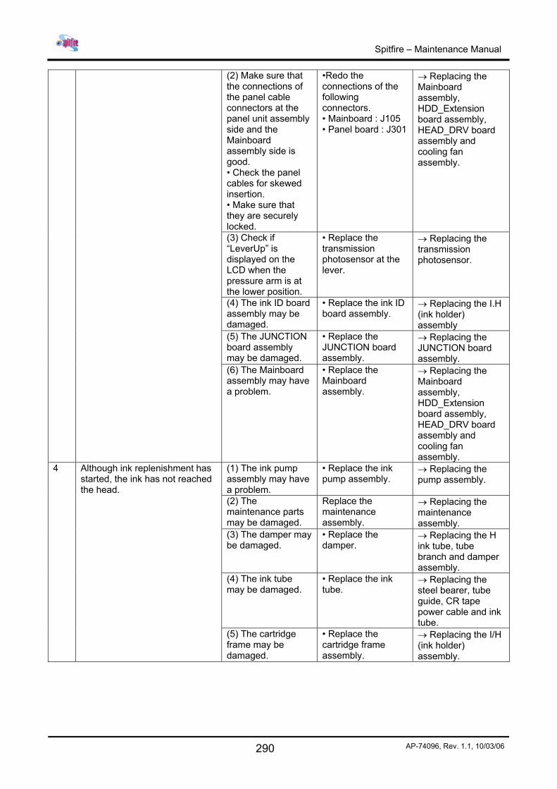
(2) Make sure that the connections of the panel cable connectors at the panel unit assembly side and the Mainboard assembly side is good. • Check the panel cables for skewed insertion. • Make sure that they are securely locked.
•Redo the connections of the following connectors. • Mainboard : J105 • Panel board : J301
→ Replacing the Mainboard assembly, HDD_Extension board assembly, HEAD_DRV board assembly and cooling fan assembly.
(3) Check if “LeverUp” is displayed on the LCD when the pressure arm is at the lower position.
• Replace the transmission photosensor at the lever.
→ Replacing the transmission photosensor.
(4) The ink ID board assembly may be damaged.
• Replace the ink ID board assembly.
→ Replacing the I.H (ink holder) assembly
(5) The JUNCTION board assembly may be damaged.
• Replace the JUNCTION board assembly.
→ Replacing the JUNCTION board assembly.
(6) The Mainboard assembly may have a problem.
• Replace the Mainboard assembly.
→ Replacing the Mainboard assembly, HDD_Extension board assembly, HEAD_DRV board assembly and cooling fan assembly.
(1) The ink pump assembly may have a problem.
• Replace the ink pump assembly.
→ Replacing the pump assembly.
(2) The maintenance parts may be damaged.
Replace the maintenance assembly.
→ Replacing the maintenance assembly.
(3) The damper may be damaged.
• Replace the damper.
→ Replacing the H ink tube, tube branch and damper assembly.
(4) The ink tube may be damaged.
• Replace the ink tube.
→ Replacing the steel bearer, tube guide, CR tape power cable and ink tube.
4 Although ink replenishment has started, the ink has not reached the head.
(5) The cartridge frame may be damaged.
• Replace the cartridge frame assembly.
→ Replacing the I/H (ink holder) assembly.
Spitfire – Maintenance Manual
291 AP-74096, Rev. 1.1, 10/03/06
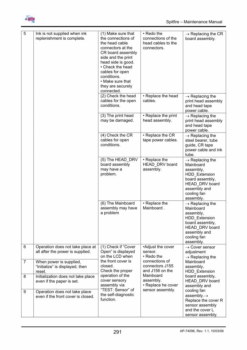
(1) Make sure that the connections of the head cable connectors at the CR board assembly side and the print head side is good. • Check the head cables for open conditions. • Make sure that they are securely connected.
• Redo the connections of the head cables to the connectors.
→ Replacing the CR board assembly.
(2) Check the head cables for the open conditions.
• Replace the head cables.
→ Replacing the print head assembly and head tape power cable.
(3) The print head may be damaged.
• Replace the print head assembly.
→ Replacing the print head assembly and head tape power cable.
(4) Check the CR cables for open conditions.
• Replace the CR tape power cables.
→ Replacing the steel bearer, tube guide, CR tape power cable and ink tube.
(5) The HEAD_DRV board assembly may have a problem.
• Replace the HEAD_DRV board assembly.
→ Replacing the Mainboard assembly, HDD_Extension board assembly, HEAD_DRV board assembly and cooling fan assembly.
5 Ink is not supplied when ink replenishment is complete.
(6) The Mainboard assembly may have a problem
• Replace the Mainboard .
→ Replacing the Mainboard assembly, HDD_Extension board assembly, HEAD_DRV board assembly and cooling fan assembly.
6 Operation does not take place at all after the power is supplied.
7 When power is supplied, “Initialize” is displayed, then reset.
8 Initialization does not take place even if the paper is set.
9 Operation does not take place even if the front cover is closed.
(1) Check if “Cover Open” is displayed on the LCD when the front cover is closed. Check the proper operation of the cover sensory assembly via “TEST: Sensor” of the self-diagnostic function.
•Adjust the cover sensor. • Redo the connections of connectors J155 and J156 on the Mainboard assembly. • Replace he cover sensor assembly.
→ Cover sensor adjustment → Replacing the Mainboard assembly, HDD_Extension board assembly, HEAD_DRV board assembly and cooling fan assembly.→ Replace the cover R sensor assembly and the cover L sensor assembly.
Spitfire – Maintenance Manual
292 AP-74096, Rev. 1.1, 10/03/06
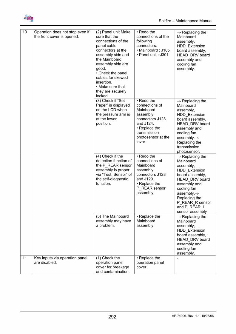
(2) Panel unit Make sure that the connections of the panel cable connectors at the assembly side and the Mainboard assembly side are good. • Check the panel cables for skewed insertion. • Make sure that they are securely locked.
• Redo the connections of the following connectors. • Mainboard : J105 • Panel unit : J301
→ Replacing the Mainboard assembly, HDD_Extension board assembly, HEAD_DRV board assembly and cooling fan assembly.
(3) Check if “Set Paper” is displayed on the LCD when the pressure arm is at the lower position.
• Redo the connections of Mainboard assembly connectors J123 and J124. • Replace the transmission photosensor at the lever.
→ Replacing the Mainboard assembly, HDD_Extension board assembly, HEAD_DRV board assembly and cooling fan assembly.→ Replacing the transmission photosensor.
(4) Check if the detection function of the P_REAR sensor assembly is proper via “Test: Sensor” of the self-diagnostic function.
• Redo the connections of Mainboard assembly connectors J128 and J129. • Replace the P_REAR sensor assembly.
→ Replacing the Mainboard assembly, HDD_Extension board assembly, HEAD_DRV board assembly and cooling fan assembly.→ Replacing the P_REAR_R sensor and P_REAR_L sensor assembly
10 Operation does not stop even if the front cover is opened.
(5) The Mainboard assembly may have a problem.
• Replace the Mainboard assembly.
→ Replacing the Mainboard assembly, HDD_Extension board assembly, HEAD_DRV board assembly and cooling fan assembly.
11 Key inputs via operation panel are disabled.
(1) Check the operation panel cover for breakage and contamination.
• Replace the operation panel cover.
-
Spitfire – Maintenance Manual
293 AP-74096, Rev. 1.1, 10/03/06
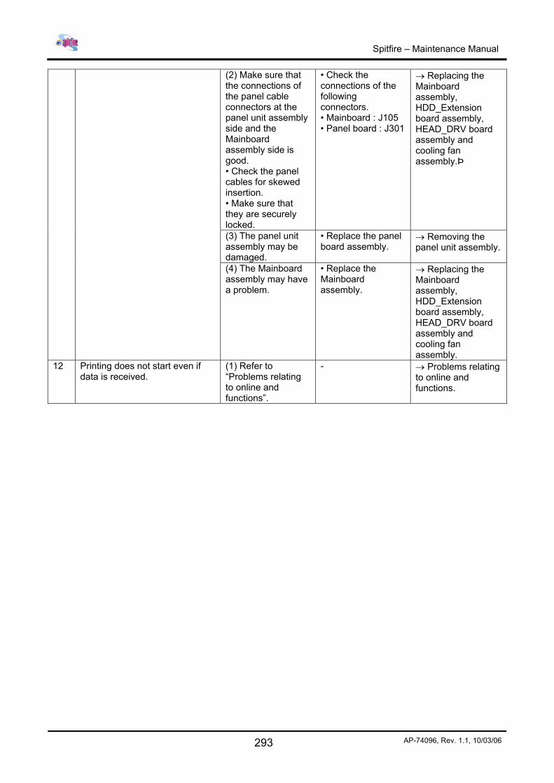
(2) Make sure that the connections of the panel cable connectors at the panel unit assembly side and the Mainboard assembly side is good. • Check the panel cables for skewed insertion. • Make sure that they are securely locked.
• Check the connections of the following connectors. • Mainboard : J105 • Panel board : J301
→ Replacing the Mainboard assembly, HDD_Extension board assembly, HEAD_DRV board assembly and cooling fan assembly.Þ
(3) The panel unit assembly may be damaged.
• Replace the panel board assembly.
→ Removing the panel unit assembly.
(4) The Mainboard assembly may have a problem.
• Replace the Mainboard assembly.
→ Replacing the Mainboard assembly, HDD_Extension board assembly, HEAD_DRV board assembly and cooling fan assembly.
12 Printing does not start even if data is received.
(1) Refer to “Problems relating to online and functions”.
- → Problems relating to online and functions.
Spitfire – Maintenance Manual
294 AP-74096, Rev. 1.1, 10/03/06
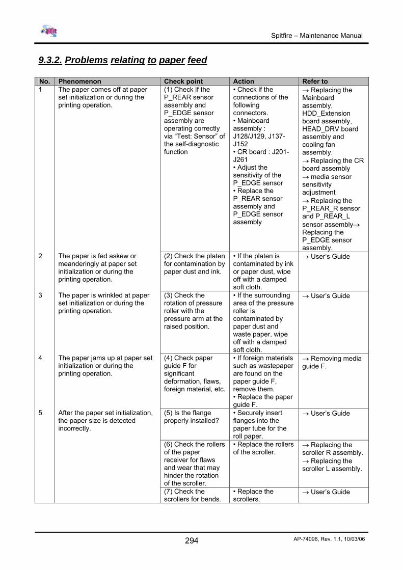
9.3.2. Problems relating to paper feed No. Phenomenon Check point Action Refer to 1 The paper comes off at paper
set initialization or during the printing operation.
(1) Check if the P_REAR sensor assembly and P_EDGE sensor assembly are operating correctly via “Test: Sensor” of the self-diagnostic function
• Check if the connections of the following connectors. • Mainboard assembly : J128/J129, J137-J152 • CR board : J201-J261 • Adjust the sensitivity of the P_EDGE sensor • Replace the P_REAR sensor assembly and P_EDGE sensor assembly
→ Replacing the Mainboard assembly, HDD_Extension board assembly, HEAD_DRV board assembly and cooling fan assembly. → Replacing the CR board assembly → media sensor sensitivity adjustment → Replacing the P_REAR_R sensor and P_REAR_L sensor assembly→ Replacing the P_EDGE sensor assembly.
2 The paper is fed askew or meanderingly at paper set initialization or during the printing operation.
(2) Check the platen for contamination by paper dust and ink.
• If the platen is contaminated by ink or paper dust, wipe off with a damped soft cloth.
→ User’s Guide
3 The paper is wrinkled at paper set initialization or during the printing operation.
(3) Check the rotation of pressure roller with the pressure arm at the raised position.
• If the surrounding area of the pressure roller is contaminated by paper dust and waste paper, wipe off with a damped soft cloth.
→ User’s Guide
4 The paper jams up at paper set initialization or during the printing operation.
(4) Check paper guide F for significant deformation, flaws, foreign material, etc.
• If foreign materials such as wastepaper are found on the paper guide F, remove them. • Replace the paper guide F.
→ Removing media guide F.
5 After the paper set initialization, the paper size is detected incorrectly.
(5) Is the flange properly installed?
• Securely insert flanges into the paper tube for the roll paper.
→ User’s Guide
(6) Check the rollers of the paper receiver for flaws and wear that may hinder the rotation of the scroller.
• Replace the rollers of the scroller.
→ Replacing the scroller R assembly. → Replacing the scroller L assembly.
(7) Check the scrollers for bends.
• Replace the scrollers.
→ User’s Guide
Spitfire – Maintenance Manual
295 AP-74096, Rev. 1.1, 10/03/06
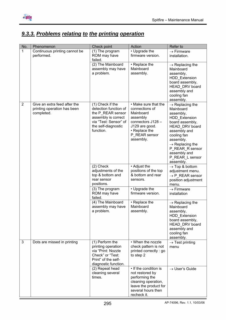
9.3.3. Problems relating to the printing operation No. Phenomenon Check point Action Refer to
(1) The program ROM may have failed.
• Upgrade the firmware version.
→ Firmware installation.
1 Continuous printing cannot be performed.
(2) The Mainboard assembly may have a problem.
• Replace the Mainboard assembly.
→ Replacing the Mainboard assembly, HDD_Extension board assembly, HEAD_DRV board assembly and cooling fan assembly.
(1) Check if the detection function of the P_REAR sensor assembly is correct via “Test: Sensor” of the self-diagnostic function.
• Make sure that the connections of Mainboard assembly connectors J128 – J129 are good. • Replace the P_REAR sensor assembly.
→ Replacing the Mainboard assembly, HDD_Extension board assembly, HEAD_DRV board assembly and cooling fan assembly. → Replacing the P_REAR_R sensor assembly and P_REAR_L sensor assembly.
(2) Check adjustments of the top & bottom and rear sensor positions.
• Adjust the positions of the top & bottom and rear sensors.
→ Top & bottom adjustment menu. → P_REAR sensor position adjustment menu.
(3) The program ROM may have failed.
• Upgrade the firmware version.
→ Firmware installation
2 Give an extra feed after the printing operation has been completed.
(4) The Mainboard assembly may have a problem.
• Replace the Mainboard assembly.
→ Replacing the Mainboard assembly, HDD_Extension board assembly, HEAD_DRV board assembly and cooling fan assembly.
(1) Perform the printing operation via “Print: Nozzle Check” or “Test: Print” of the self-diagnostic function.
• When the nozzle check pattern is not printed correctly : go to step 2
→ Test printing menu
3 Dots are missed in printing
(2) Repeat head cleaning several times.
• If the condition is not restored by performing the cleaning operation, leave the product for several hours then recheck it.
→ User’s Guide
Spitfire – Maintenance Manual
296 AP-74096, Rev. 1.1, 10/03/06
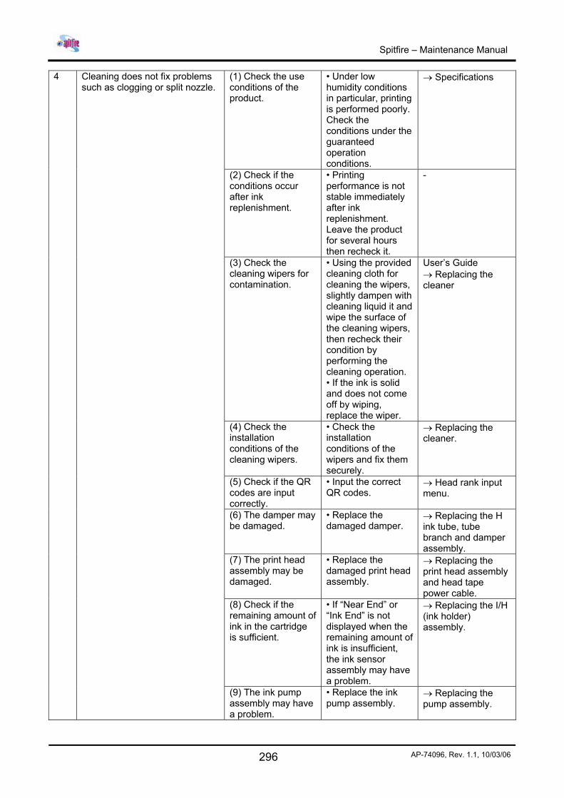
(1) Check the use conditions of the product.
• Under low humidity conditions in particular, printing is performed poorly. Check the conditions under the guaranteed operation conditions.
→ Specifications
(2) Check if the conditions occur after ink replenishment.
• Printing performance is not stable immediately after ink replenishment. Leave the product for several hours then recheck it.
-
(3) Check the cleaning wipers for contamination.
• Using the provided cleaning cloth for cleaning the wipers, slightly dampen with cleaning liquid it and wipe the surface of the cleaning wipers, then recheck their condition by performing the cleaning operation. • If the ink is solid and does not come off by wiping, replace the wiper.
User’s Guide → Replacing the cleaner
(4) Check the installation conditions of the cleaning wipers.
• Check the installation conditions of the wipers and fix them securely.
→ Replacing the cleaner.
(5) Check if the QR codes are input correctly.
• Input the correct QR codes.
→ Head rank input menu.
(6) The damper may be damaged.
• Replace the damaged damper.
→ Replacing the H ink tube, tube branch and damper assembly.
(7) The print head assembly may be damaged.
• Replace the damaged print head assembly.
→ Replacing the print head assembly and head tape power cable.
(8) Check if the remaining amount of ink in the cartridge is sufficient.
• If “Near End” or “Ink End” is not displayed when the remaining amount of ink is insufficient, the ink sensor assembly may have a problem.
→ Replacing the I/H (ink holder) assembly.
4 Cleaning does not fix problems such as clogging or split nozzle.
(9) The ink pump assembly may have a problem.
• Replace the ink pump assembly.
→ Replacing the pump assembly.
Spitfire – Maintenance Manual
297 AP-74096, Rev. 1.1, 10/03/06
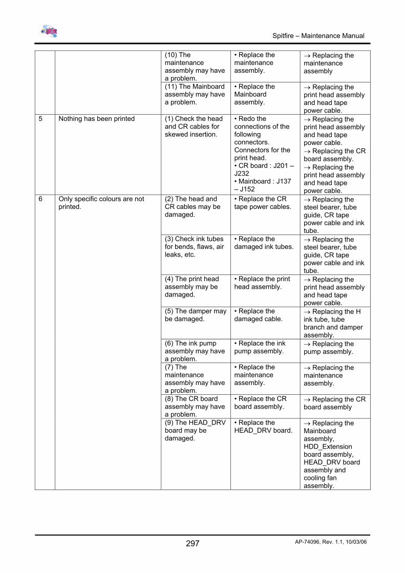
(10) The maintenance assembly may have a problem.
• Replace the maintenance assembly.
→ Replacing the maintenance assembly
(11) The Mainboard assembly may have a problem.
• Replace the Mainboard assembly.
→ Replacing the print head assembly and head tape power cable.
5 Nothing has been printed (1) Check the head and CR cables for skewed insertion.
• Redo the connections of the following connectors. Connectors for the print head. • CR board : J201 – J232 • Mainboard : J137 – J152
→ Replacing the print head assembly and head tape power cable. → Replacing the CR board assembly. → Replacing the print head assembly and head tape power cable.
(2) The head and CR cables may be damaged.
• Replace the CR tape power cables.
→ Replacing the steel bearer, tube guide, CR tape power cable and ink tube.
(3) Check ink tubes for bends, flaws, air leaks, etc.
• Replace the damaged ink tubes.
→ Replacing the steel bearer, tube guide, CR tape power cable and ink tube.
(4) The print head assembly may be damaged.
• Replace the print head assembly.
→ Replacing the print head assembly and head tape power cable.
(5) The damper may be damaged.
• Replace the damaged cable.
→ Replacing the H ink tube, tube branch and damper assembly.
(6) The ink pump assembly may have a problem.
• Replace the ink pump assembly.
→ Replacing the pump assembly.
(7) The maintenance assembly may have a problem.
• Replace the maintenance assembly.
→ Replacing the maintenance assembly.
(8) The CR board assembly may have a problem.
• Replace the CR board assembly.
→ Replacing the CR board assembly
6 Only specific colours are not printed.
(9) The HEAD_DRV board may be damaged.
• Replace the HEAD_DRV board.
→ Replacing the Mainboard assembly, HDD_Extension board assembly, HEAD_DRV board assembly and cooling fan assembly.
Spitfire – Maintenance Manual
298 AP-74096, Rev. 1.1, 10/03/06
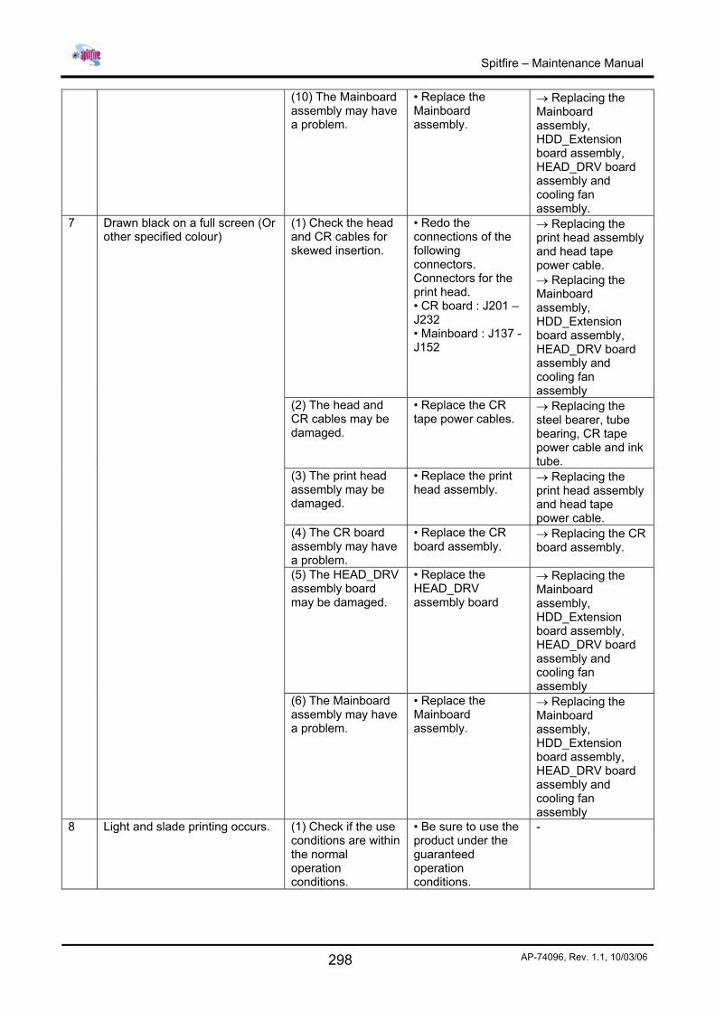
(10) The Mainboard assembly may have a problem.
• Replace the Mainboard assembly.
→ Replacing the Mainboard assembly, HDD_Extension board assembly, HEAD_DRV board assembly and cooling fan assembly.
(1) Check the head and CR cables for skewed insertion.
• Redo the connections of the following connectors. Connectors for the print head. • CR board : J201 – J232 • Mainboard : J137 - J152
→ Replacing the print head assembly and head tape power cable. → Replacing the Mainboard assembly, HDD_Extension board assembly, HEAD_DRV board assembly and cooling fan assembly
(2) The head and CR cables may be damaged.
• Replace the CR tape power cables.
→ Replacing the steel bearer, tube bearing, CR tape power cable and ink tube.
(3) The print head assembly may be damaged.
• Replace the print head assembly.
→ Replacing the print head assembly and head tape power cable.
(4) The CR board assembly may have a problem.
• Replace the CR board assembly.
→ Replacing the CR board assembly.
(5) The HEAD_DRV assembly board may be damaged.
• Replace the HEAD_DRV assembly board
→ Replacing the Mainboard assembly, HDD_Extension board assembly, HEAD_DRV board assembly and cooling fan assembly
7 Drawn black on a full screen (Or other specified colour)
(6) The Mainboard assembly may have a problem.
• Replace the Mainboard assembly.
→ Replacing the Mainboard assembly, HDD_Extension board assembly, HEAD_DRV board assembly and cooling fan assembly
8 Light and slade printing occurs. (1) Check if the use conditions are within the normal operation conditions.
• Be sure to use the product under the guaranteed operation conditions.
-
Spitfire – Maintenance Manual
299 AP-74096, Rev. 1.1, 10/03/06
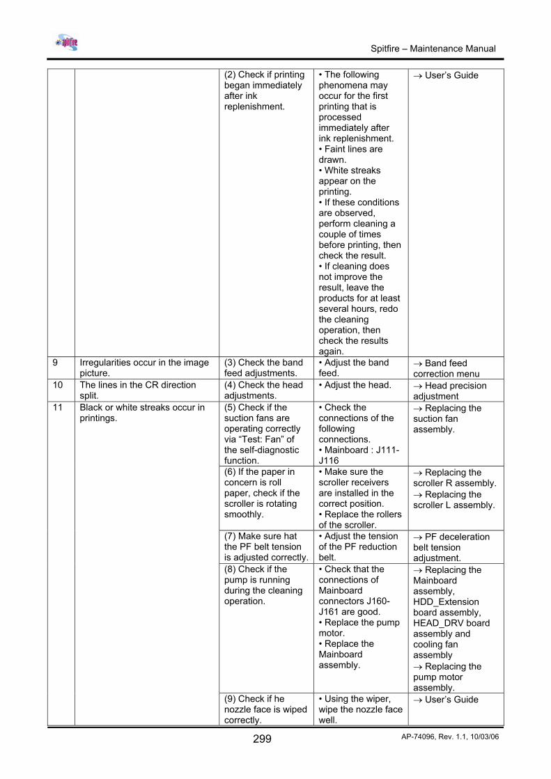
(2) Check if printing began immediately after ink replenishment.
• The following phenomena may occur for the first printing that is processed immediately after ink replenishment. • Faint lines are drawn. • White streaks appear on the printing. • If these conditions are observed, perform cleaning a couple of times before printing, then check the result. • If cleaning does not improve the result, leave the products for at least several hours, redo the cleaning operation, then check the results again.
→ User’s Guide
9 Irregularities occur in the image picture.
(3) Check the band feed adjustments.
• Adjust the band feed.
→ Band feed correction menu
10 The lines in the CR direction split.
(4) Check the head adjustments.
• Adjust the head. → Head precision adjustment
(5) Check if the suction fans are operating correctly via “Test: Fan” of the self-diagnostic function.
• Check the connections of the following connections. • Mainboard : J111-J116
→ Replacing the suction fan assembly.
(6) If the paper in concern is roll paper, check if the scroller is rotating smoothly.
• Make sure the scroller receivers are installed in the correct position. • Replace the rollers of the scroller.
→ Replacing the scroller R assembly. → Replacing the scroller L assembly.
(7) Make sure hat the PF belt tension is adjusted correctly.
• Adjust the tension of the PF reduction belt.
→ PF deceleration belt tension adjustment.
(8) Check if the pump is running during the cleaning operation.
• Check that the connections of Mainboard connectors J160-J161 are good. • Replace the pump motor. • Replace the Mainboard assembly.
→ Replacing the Mainboard assembly, HDD_Extension board assembly, HEAD_DRV board assembly and cooling fan assembly → Replacing the pump motor assembly.
11 Black or white streaks occur in printings.
(9) Check if he nozzle face is wiped correctly.
• Using the wiper, wipe the nozzle face well.
→ User’s Guide
Spitfire – Maintenance Manual
300 AP-74096, Rev. 1.1, 10/03/06
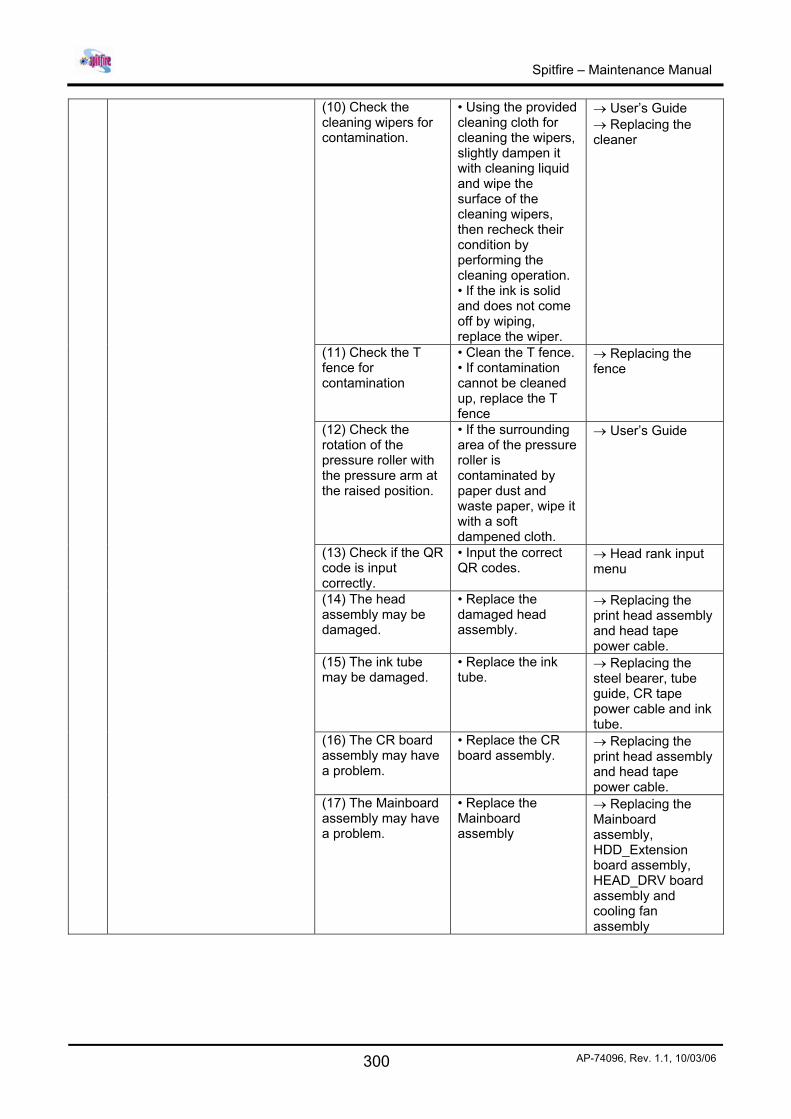
(10) Check the cleaning wipers for contamination.
• Using the provided cleaning cloth for cleaning the wipers, slightly dampen it with cleaning liquid and wipe the surface of the cleaning wipers, then recheck their condition by performing the cleaning operation. • If the ink is solid and does not come off by wiping, replace the wiper.
→ User’s Guide → Replacing the cleaner
(11) Check the T fence for contamination
• Clean the T fence. • If contamination cannot be cleaned up, replace the T fence
→ Replacing the fence
(12) Check the rotation of the pressure roller with the pressure arm at the raised position.
• If the surrounding area of the pressure roller is contaminated by paper dust and waste paper, wipe it with a soft dampened cloth.
→ User’s Guide
(13) Check if the QR code is input correctly.
• Input the correct QR codes.
→ Head rank input menu
(14) The head assembly may be damaged.
• Replace the damaged head assembly.
→ Replacing the print head assembly and head tape power cable.
(15) The ink tube may be damaged.
• Replace the ink tube.
→ Replacing the steel bearer, tube guide, CR tape power cable and ink tube.
(16) The CR board assembly may have a problem.
• Replace the CR board assembly.
→ Replacing the print head assembly and head tape power cable.
(17) The Mainboard assembly may have a problem.
• Replace the Mainboard assembly
→ Replacing the Mainboard assembly, HDD_Extension board assembly, HEAD_DRV board assembly and cooling fan assembly
Spitfire – Maintenance Manual
301 AP-74096, Rev. 1.1, 10/03/06
(1) Check if the condition is recovered by cleaning.
• If the condition is not recovered by performing the cleaning operation a couple of times, leave the product for a while then recheck it.
→ User’s Guide
(2) Check if the set paper is one of those recommended by MUTOH.
• Reset the recommended paper and recheck the condition. If paper not recommended by MUTOH is used, the paper may not be recognized correctly by the paper sensor. • Check the condition using the printing mode that is recommended for the paper.
→ User’s Guide
(3) Check the head adjustments.
• Adjust the head. → Head precision adjustment
(4) Check if the QR code is input correctly.
• Input the correct QR codes.
→ Head rank input menu
(5) The CR cables may be damaged.
• Replace the CR tape power cables.
→ Replacing the steel bearer, tube guide, CR tape power cable and ink tube.
(6) Check the head assembly for breakage.
• Replace the damaged head assembly
→ Replacing the print head assembly and head tape power cable.
(7) The CR board assembly may have a problem.
• Replace the CR board assembly.
→ Replacing the CR board assembly
12 The printing boundary is smeared.
(8) The Mainboard assembly may have a problem.
• Replace the Mainboard assembly
→ Replacing the Mainboard assembly, HDD_Extension board assembly, HEAD_DRV board assembly and cooling fan assembly
13 There are many satellite droplets (unnecessary dots)
(1) Check if the use conditions are within the normal operation conditions.
• Be sure to use the product under the guaranteed operation conditions.
Spitfire – Maintenance Manual
302 AP-74096, Rev. 1.1, 10/03/06
14 Fiber tracking is shown in prints. (2) Check if printing began immediately after ink replenishment.
• The following phenomena may occur for the first printing processed immediately after ink replenishment. • Faint lines are drawn. • White streaks appear on the printing. • If these conditions are observed, perform cleaning a couple of times before printing, then check the results. • If cleaning does not improve the results, leave the products for at least several hours, redo the cleaning operation, then check the results again.
→ User’s Guide
15 Lines look blurred when printed. (3) Check if the tension of the steel belt is properly adjusted.
• Adjust the steel belt tension.
→ Steel belt tension adjustment
(4) Check the head adjustments.
• Adjust the head. → Head precision adjustment
(5) Check the T fence for contamination.
• Clean the T fence • If contaminants cannot be cleaned up by cleaning, replace the T fence.
→ Replacing the T fence
(6) Make sure that the CR_ENC assembly and the T fence are not interfering.
• If they interfere with each other, adjust the installation positions of the CR_ENC assembly and the T fence. • If the adjustments do not improve this, replace the CR_ENC assembly and the T fence.
→ Replacing the T fence. → Replacing the CR_ENC assembly
(7) Check if the pump is running during the cleaning operation.
• Check that connections of Mainboard connectors J160-J161 are good. • Replace the pump motor assembly. • Replace the Mainboard assembly.
→ Replacing the Mainboard assembly, HDD_Extension board assembly, HEAD_DRV board assembly and cooling fan assembly → Replacing the pump motor assembly.
Spitfire – Maintenance Manual
303 AP-74096, Rev. 1.1, 10/03/06
(8) Check if the nozzle face is wiped correctly.
• Using the wiper, wipe the nozzle face well.
→ User’s Guide
(9) Check the cleaning wipers for contamination.
• Using the provided cleaning cloth for cleaning the wipers, slightly dampen it with cleaning liquid and wipe the surfaces of the cleaning wipers, then recheck their conditions by performing the cleaning operation. • If the ink is solid and does not come off by wiping, replace the wiper.
→ User’s Guide. → Replacing the cleaner
(10) Check if the QR code is input correctly.
• Input the correct QR codes.
→ Head rank input menu
(11) The head assembly may be damaged.
• Replace the damaged head assembly
→ Replacing the print head assembly and head tape power cable.
(12) The ink tube may be damaged.
• Replace the ink tube.
→ Replacing the steel bearer, tube guide, CR tape power cable and ink tube.
(13) The CR board may have a problem.
• Replace the CR board assembly.
→ Replacing the CR board assembly.
(14) The Mainboard assembly may have a problem.
• Replace the Mainboard assembly.
→ Replacing the Mainboard assembly, HDD_Extension board assembly, HEAD_DRV board assembly and cooling fan assembly
16 Mixed colour lines do not overlap.
(1) Check if the tension of the steel belt is properly adjusted.
• Adjust the steel belt tension.
→ Steel belt tension adjustment
17 The positions of black and colours are not aligned.
(2) Check the head inclination and height adjustments.
• Adjust the inclination and height of the head.
→ Head precision adjustment
(3) Check the two-way printing position alignment for problems.
• Adjust the two-way printing position alignment.
→ Repeatability alignment menu
(4) Check if CW adjustments are made correctly.
• Perform the CW adjustments.
→ CW adjustment menu
(5) Check if the QR code is input correctly.
• Input the correct QR codes.
→ Head rank input menu
Spitfire – Maintenance Manual
304 AP-74096, Rev. 1.1, 10/03/06
(6) Make sure that the CR_ENC assembly and the T fence are not interfering.
• If they are interfering with each other, adjust the installation positions of the CR_ENC assembly and the T fence. • If the adjustments do not improve this, replace the CR_ENC assembly and the T fence.
→ Replacing the T fence. → Replacing the CR_ENC assembly.
(7) The head assembly may be damaged.
• Replace the damaged head assembly.
→ Replacing the print head assembly and head tape power cable.
(1) Check if the use conditions are within the normal operation conditions.
• be sure to use the product under the operation conditions.
-
(2) Check if the tension of the steel belt is adjusted correctly.
• Adjust the steel belt tension.
→ Steel belt tension adjustment
(3) Check the T fence for contamination.
• Clean the T fence • If the contaminants cannot be cleaned up, replace the T fence.
→ Replacing the T fence.
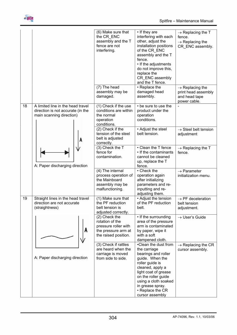
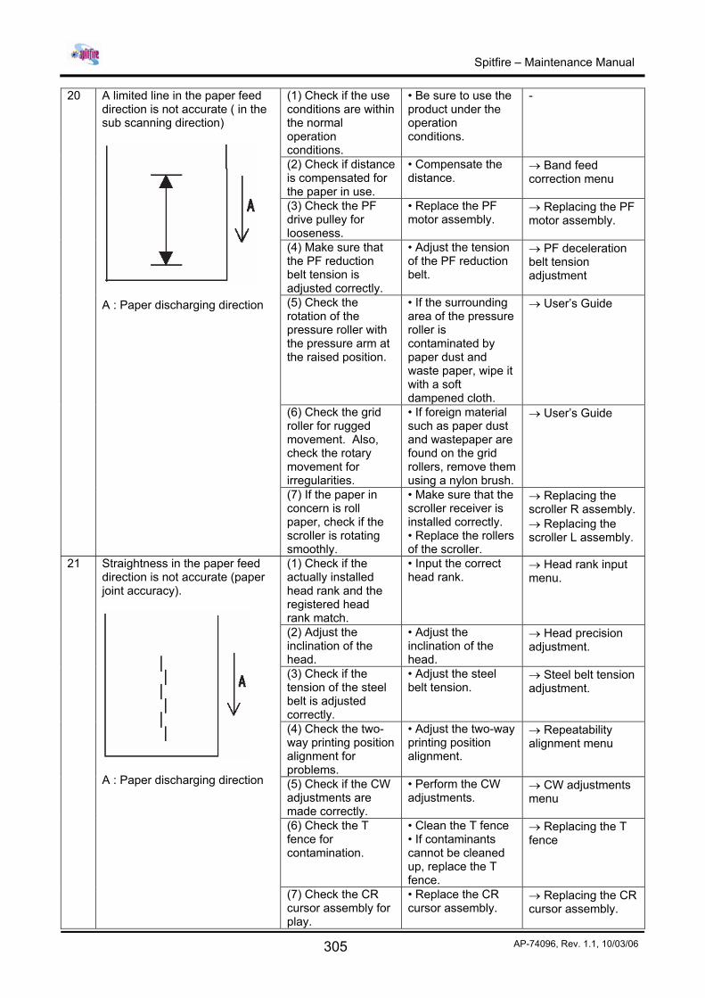
18 A limited line in the head travel direction is not accurate (in the main scanning direction)
A: Paper discharging direction
(4) The internal process operation of the Mainboard assembly may be malfunctioning.
• Check the operation again after initializing parameters and re-inputting and re-adjusting them.
→ Parameter initialization menu.
(1) Make sure that the PF reduction belt tension is adjusted correctly.
• Adjust the tension of the PF reduction belt.
→ PF deceleration belt tension adjustment.
(2) Check the rotation of the pressure roller with the pressure arm at the raised position.
• If the surrounding area of the pressure arm is contaminated by paper, wipe it with a soft dampened cloth.
→ User’s Guide
19 Straight lines in the head travel direction are not accurate (straightness)
A: Paper discharging direction
(3) Check if rattles are heard when the carriage is moved from side to side.
•Clean the dust from the carriage bearings and roller guide. When the roller guide is cleaned, apply a light coat of grease on the roller guide using a cloth soaked in grease spray. • Replace the CR cursor assembly
→ Replacing the CR cursor assembly.
Spitfire – Maintenance Manual
305 AP-74096, Rev. 1.1, 10/03/06
(1) Check if the use conditions are within the normal operation conditions.
• Be sure to use the product under the operation conditions.
-
(2) Check if distance is compensated for the paper in use.
• Compensate the distance.
→ Band feed correction menu
(3) Check the PF drive pulley for looseness.
• Replace the PF motor assembly.
→ Replacing the PF motor assembly.
(4) Make sure that the PF reduction belt tension is adjusted correctly.
• Adjust the tension of the PF reduction belt.
→ PF deceleration belt tension adjustment
(5) Check the rotation of the pressure roller with the pressure arm at the raised position.
• If the surrounding area of the pressure roller is contaminated by paper dust and waste paper, wipe it with a soft dampened cloth.
→ User’s Guide
(6) Check the grid roller for rugged movement. Also, check the rotary movement for irregularities.
• If foreign material such as paper dust and wastepaper are found on the grid rollers, remove them using a nylon brush.
→ User’s Guide
20 A limited line in the paper feed direction is not accurate ( in the sub scanning direction)
A : Paper discharging direction
(7) If the paper in concern is roll paper, check if the scroller is rotating smoothly.
• Make sure that the scroller receiver is installed correctly. • Replace the rollers of the scroller.
→ Replacing the scroller R assembly. → Replacing the scroller L assembly.
(1) Check if the actually installed head rank and the registered head rank match.
• Input the correct head rank.
→ Head rank input menu.
(2) Adjust the inclination of the head.
• Adjust the inclination of the head.
→ Head precision adjustment.
(3) Check if the tension of the steel belt is adjusted correctly.
• Adjust the steel belt tension.
→ Steel belt tension adjustment.
(4) Check the two-way printing position alignment for problems.
• Adjust the two-way printing position alignment.
→ Repeatability alignment menu
(5) Check if the CW adjustments are made correctly.
• Perform the CW adjustments.
→ CW adjustments menu
(6) Check the T fence for contamination.
• Clean the T fence • If contaminants cannot be cleaned up, replace the T fence.
→ Replacing the T fence
21 Straightness in the paper feed direction is not accurate (paper joint accuracy).
A : Paper discharging direction
(7) Check the CR cursor assembly for play.
• Replace the CR cursor assembly.
→ Replacing the CR cursor assembly.
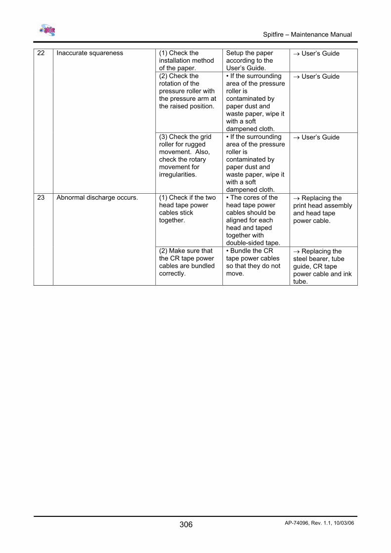
Spitfire – Maintenance Manual
306 AP-74096, Rev. 1.1, 10/03/06
(1) Check the installation method of the paper.
Setup the paper according to the User’s Guide.
→ User’s Guide
(2) Check the rotation of the pressure roller with the pressure arm at the raised position.
• If the surrounding area of the pressure roller is contaminated by paper dust and waste paper, wipe it with a soft dampened cloth.
→ User’s Guide
22 Inaccurate squareness
(3) Check the grid roller for rugged movement. Also, check the rotary movement for irregularities.
• If the surrounding area of the pressure roller is contaminated by paper dust and waste paper, wipe it with a soft dampened cloth.
→ User’s Guide
(1) Check if the two head tape power cables stick together.
• The cores of the head tape power cables should be aligned for each head and taped together with double-sided tape.
→ Replacing the print head assembly and head tape power cable.
23 Abnormal discharge occurs.
(2) Make sure that the CR tape power cables are bundled correctly.
• Bundle the CR tape power cables so that they do not move.
→ Replacing the steel bearer, tube guide, CR tape power cable and ink tube.
Spitfire – Maintenance Manual
307 AP-74096, Rev. 1.1, 10/03/06
9.3.4. Problems relating to noise No. Phenomenon Check point Action Refer to
(1) Check the surroundings of the suction fan assembly for obstructions and foreign objects.
• Remove obstructions and foreign material.
→ Replacing the suction fan assembly.
(2) Check the cables for damage and make sure that the connector connections are good.
• If damage is found, replace the appropriate parts.
-
(3) The suction fan assembly may have failed.
• Replace the suction fan assembly.
→ Replacing the suction fan assembly.
(4) The Mainboard assembly may have failed.
• Replace the Mainboard assembly
→ Replacing the Mainboard assembly, HDD_Extension board assembly, HEAD_DRV board assembly and cooling fan assembly
1 There is noise when the paper is loaded.
(5) The power supply board assembly may have a problem.
• Replace the power supply board assembly.
→ Replacing the power source board assembly.
2 You hear some noise during printing wait.
(1) Check the area where there is noise from for obstruction and foreign materials.
• Remove the obstructions and foreign materials.
-
(1) Check if the high pitch sound emitted while ink is discharging during printing, is not confused with the noise.
• Follow the descriptions in the specifications.
- 3 You hear some noise when the head is moving from side to side.
(2) Check the screws on the cover for looseness that causes noise.
• Re-tighten the screws.
→ Removing the cover.
Spitfire – Maintenance Manual
308 AP-74096, Rev. 1.1, 10/03/06
(3) Check if rattles are heard when the carriage is moving from side to side.
• Clean the dust from the carriage bearings and roller guide. When the roller guide has been cleaned, apply a light coat of grease on the roller guide using a cloth soaked in grease spray. • Replace the CR cursor assembly.
→ Replacing the CR cursor assembly
(4) Check the CR cables for noise.
• Correct the cable’s tendency and fix the condition. • If noise is heard from between the steel bearing and tube guide, replace the tube guide.
→ Replacing the steel bearer, tube guide, CR tape power cable and ink tube.
(5) Make sure that the CR_ENC assembly and the T fence are not interfering.
• If interference is observed, adjust the installation positions of the appropriate components. • If the adjustment does not improve this, replace the appropriate components.
→ Replacing the T fence → Replacing the CR_ENC assembly
(6) Check the bearings of the CR driven pulley for noise.
• Replace the CR driven pulley assembly.
→ Replacing the CR slave pulley assembly.
(7) Check if the tension of the steel belt has been properly adjusted.
• Adjust the steel belt tension.
→ Steel belt tension adjustment.
(8) Check the CR motor assembly for noise.
• Replace the CR motor assembly.
→ Replacing the CR motor assembly.
(9) Check the cursor roller of the CR cursor assembly for noise.
• Replace the cursor roller.
→ Replacing the cursor roller assembly.
(1) Check the PF reduction belt for the skipping of teeth between the belt and PF reduction pulley.
• Replace the PF reduction belt.
→ Replacing the PF motor assembly
(2) Check the PF motor assembly for noise
• Replace the PF motor assembly.
→ Replacing the PF motor assembly
4 You hear some noise when the paper is fed.
(3) Check the grid roller for rugged movement. Also, check the rotary movement for irregularities.
• If foreign materials such as paper dust and waste paper are found on the grid rollers, remove it using a nylon brush.
→ User’s Guide.
Spitfire – Maintenance Manual
309 AP-74096, Rev. 1.1, 10/03/06
9.3.5. Problems relating to the paper cutting operation No. Phenomenon Check point Action Refer to
(1) Check the operation panel and make sure that the media cutting setting is not set to off or manual.
• Change the setting.
→ User’s Guide
(2) Check the operation panel and make sure that PaperDet. has not been set to TakeUpRoll.
• Change the setting.
→ User’s Guide
(3) Check the cutter grooves for accumulated paper dust and clips.
• Remove the accumulated paper dust along the direction of the grooves.
→ User’s Guide
(4) Is the cutter cap securely installed?
• Reset the cutter cap securely.
→ User’s Guide
(5) Check the cutter’s up and down sliding operation.
• If it does not rise : go to step 4 • if it rises : go to step 5
-
(6) Check if the cutter drops to the bottom end under its own weight when the cutter is installed without the cutter spring.
• If it drops : The cutter spring may have a problem. Replace the cutter spring while referring to the unfolded view. • If it does not drop : The cutter may have a problem. Replace the cutter. If the cutter does not drop after it is replaced, replace the cutter holder.
→ Replacing the cutter holder, cutter spring, cutter cap, solenoid assembly and solenoid spring.
(7) Check the up and down operation of the solenoid via “Life/Cutter” of the self-diagnostic function.
1 The cutting operation is not performing correctly.
a) The solenoid moves up and down: check the cutter’s down position relative to the cutter groove.
OK : The cutter’s service life has exceeded or the cutter is damaged. Replace the cutter. NG : Adjust the position of the cutter holder.
→ User’s Guide → Cutter adjustment
Spitfire – Maintenance Manual
310 AP-74096, Rev. 1.1, 10/03/06
b) It does not move up or down.
• The connectors may have poor contacts. Check the connections of the following connectors. • CR board : J235 • CR board : J201-J216 • Mainboard : J137-J152
→ Replacing the CR board assembly → Replacing the Mainboard assembly, HDD_Extension board assembly, HEAD_DRV board assembly and cooling fan assembly
(8) Open CR cable, faulty solenoid assembly, faulty board assembly, etc. may be the causes.
• Replace the CR tape power cables. • Replace the solenoid assembly • Replace the CR board assembly • Replace the Mainboard assembly
→ Replacing the steel bearer, tube guide, CR tape power cable and ink tube. → Replacing the cutter holder, cutter spring, cutter cap, solenoid assembly and solenoid spring. → Replacing the CR board assembly → Replacing the Mainboard assembly, HDD_Extension board assembly, HEAD_DRV board assembly and cooling fan assembly
(1) Check if the paper (output) size on the application side is correct.
• Correct the paper (output) size on the application side.
-
(2) The program ROM may have failed.
• Upgrade the firmware version.
→ Firmware installation
(3) Check the CR cables for skewed insertion.
• Check the connections of the following connectors. • CR board : J235 • CR board : J201-J216 • Mainboard : J137 – J152
→ Replacing the CR board assembly
(4) The CR board may have a problem.
• Replace the CR board.
→ Replacing the CR board assembly
2 Cutting has been performed during printing.
(5) The Mainboard may have a problem.
• Replace the Mainboard .
→ Replacing the Mainboard assembly, HDD_Extension board assembly, HEAD_DRV board assembly and cooling fan assembly
Spitfire – Maintenance Manual
311 AP-74096, Rev. 1.1, 10/03/06
3 The cutting operation is in process, but the paper has not been cut.
(1) Check the cutter blade for shipping and deterioration.
• Replace the cutter. → User’s Guide
4 The paper has not been cut as smoothly as expected, resulting in jamming.
(2) Check if the cutter cap is securely installed.
• Reset the cutter cap securely.
→ User’s Guide
(3) Check if the cutter moves up and down smoothly.
• Reinstall the cutter spring.
-
(4) Check the cutter grooves for accumulated paper dust and slips.
• Remove the accumulated paper dust along the direction of the grooves.
→ User’s Guide
(5) Check if the cutter blade is parallel with the groove.
• Make adjustments. → Replacing the cutter holder, cutter spring, cutter cap, solenoid assembly and solenoid spring.
(1) The sub-platen (cutter groove) requires daily maintenance.
• Clean the surface of the sub-platen
5 The cutting operation is in process but the paper does not fall off. (2) The sub-platen, paper
guide or the paper may be charged with static electricity.
• Provide a proper ground. • Check and adjust the ambient humidity so that it meets the normal operation conditions of the product and paper.
-
(1) Check the cutter blade for chipping and deterioration.
• Replace the cutter. → User’s Guide
(2) Has the cutter cap been securely installed?
• Reset the cutter cap securely.
→ User’s Guide
(3) Check if the cutter moves up and down smoothly.
• Reinstall the cutter spring.
-
(4) Check the cutter grooves for accumulated paper dust and slips.
• Remove the accumulated paper dust along the direction of the grooves.
→ User’s Guide
(5) Check if the cutter blade is parallel with the groove.
• Make adjustments. → Replacing the cutter holder, cutter spring, cutter cap, solenoid assembly and solenoid spring.
6 Inaccurate paper cutting
(6) The cutter may have a problem.
• Replace the cutter. → User’s Guide
(1) Check the operation panel and make sure the InkDryTime has not been set.
• Change the settings.
→ User’s Guide 7 Cutting starts after the completion of the print.
(2) Check the LCD and see if messages for an analysis have been displayed.
• Printing data remains.
→ User’s Guide
Spitfire – Maintenance Manual
312 AP-74096, Rev. 1.1, 10/03/06
9.3.6. Problems relating to online and functions No. Phenomenon Check point Action Refer to
(1) Check the Centronics settings in the operation panel.
• Change the setting. → User’s Guide
(2) Replace the interface cables and see if errors still occur.
• Trouble such as an open interface cable or cables that are too long may cause communication failure. An instruction must be given so that only cables compliant with the standard are used.
-
(3) The program ROM may have failed.
• Upgrade the firmware version.
→ Firmware installation
1 Online has not been properly established by Centronics.
(4) The Mainboard assembly may have a problem.
• Replace the Mainboard assembly.
→ Replacing the Mainboard assembly, HDD_Extension board assembly, HEAD_DRV board assembly and cooling fan assembly
(1) Check if the cables in use for connections are correct.
• Use 100BASE-T cross cables for direct connections to the host. • Use 100BASE-T straight cables for connections using HUBs.
- 2 Online has not been properly established by the network.
(2) Check the network settings in the operation panel for problems.
• Reset the settings upon confirmation by an network administrator.
→ User’s Guide
3 Scaling is not functioning correctly.
(1) The program ROM may have failed.
• Upgrade the firmware version
→ Firmware installation
4 Mirroring is not functioning correctly.
5 Other functions are not performing correctly.
(2) The Mainboard assembly may have a problem.
• Replace the Mainboard assembly
→ Replacing the Mainboard assembly, HDD_Extension board assembly, HEAD_DRV board assembly and cooling fan assembly
(1) Check if CW adjustments are made correctly.
• Make adjustments. → CW adjustment menu
(2) Check the top & bottom adjustments
• Make adjustments. → Top & Bottom adjustment menu
(3) The program ROM may have failed.
• Upgrade the firmware version
→ Firmware installation
6 The printing position has been misaligned.
(4) The Mainboard assembly may have a problem.
• Replace the Mainboard assembly
→ Replacing the Mainboard assembly, HDD_Extension board assembly, HEAD_ DRV board assembly and cooling fan assembly
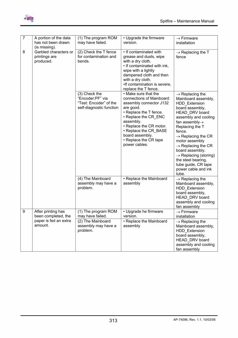
Spitfire – Maintenance Manual
313 AP-74096, Rev. 1.1, 10/03/06
7 A portion of the data
has not been drawn (is missing).
(1) The program ROM may have failed.
• Upgrade the firmware version.
→ Firmware installation
8 Garbled characters or printings are produced.
(2) Check the T fence for contamination and bends.
• If contaminated with grease and dusts, wipe with a dry cloth. • If contaminated with ink, wipe with a lightly dampened cloth and then with a dry cloth. •If contamination is severe, replace the T fence.
→ Replacing the T fence
(3) Check the “Encoder:PF” via “Test: Encoder” of the self-diagnostic function
• Make sure that the connections of Mainboard assembly connector J132 are good. • Replace the T fence. • Replace the CR_ENC assembly. • Replace the CR motor. • Replace the CR_BASE board assembly. • Replace the CR tape power cables.
→ Replacing the Mainboard assembly, HDD_Extension board assembly, HEAD_DRV board assembly and cooling fan assembly→ Replacing the T fence. → Replacing the CR motor assembly → Replacing the CR board assembly. → Replacing (storing) the steel bearing, tube guide, CR tape power cable and ink tube.
(4) The Mainboard assembly may have a problem.
• Replace the Mainboard assembly
→ Replacing the Mainboard assembly, HDD_Extension board assembly, HEAD_DRV board assembly and cooling fan assembly
(1) The program ROM may have failed.
• Upgrade he firmware version.
→ Firmware installation
9 After printing has been completed, the paper is fed an extra amount.
(2) The Mainboard assembly may have a problem.
• Replace the Mainboard assembly
→ Replacing the Mainboard assembly, HDD_Extension board assembly, HEAD_DRV board assembly and cooling fan assembly
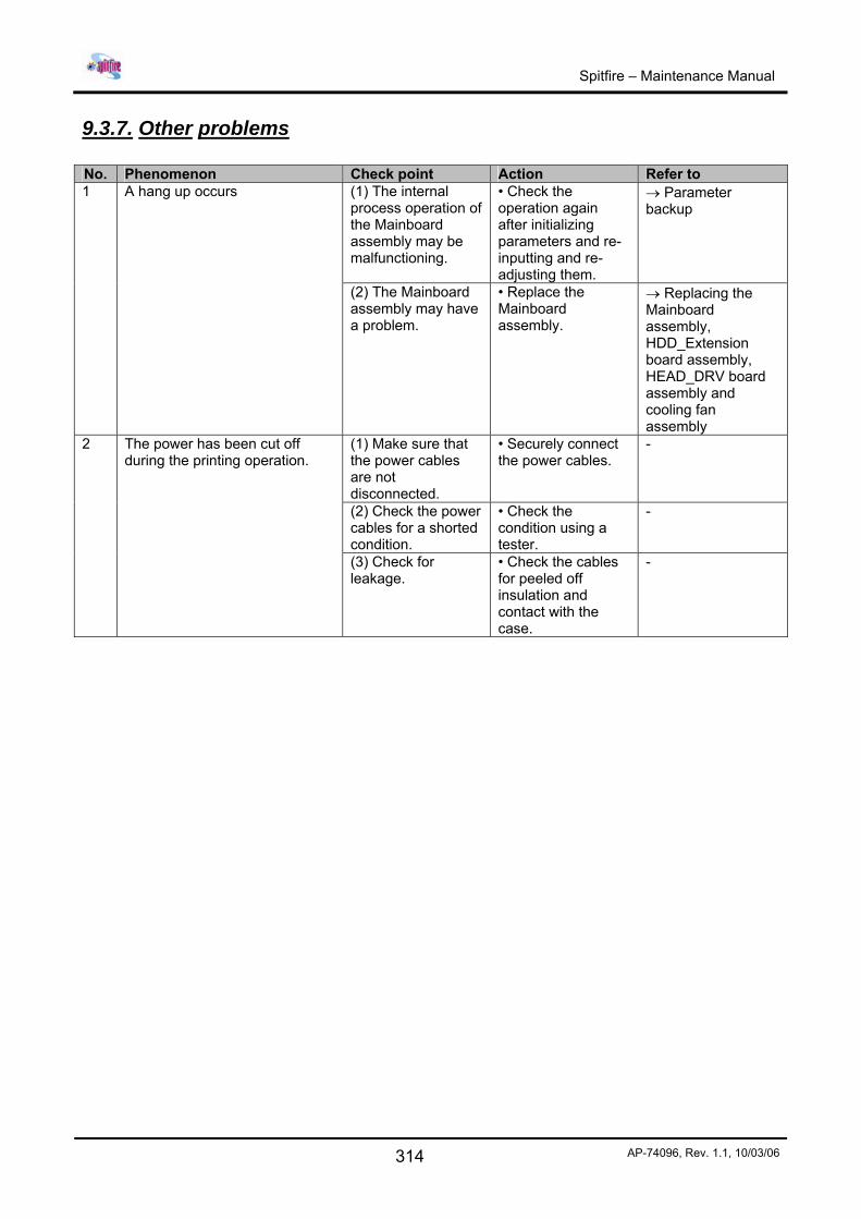
Spitfire – Maintenance Manual
314 AP-74096, Rev. 1.1, 10/03/06
9.3.7. Other problems No. Phenomenon Check point Action Refer to
(1) The internal process operation of the Mainboard assembly may be malfunctioning.
• Check the operation again after initializing parameters and re-inputting and re-adjusting them.
→ Parameter backup
1 A hang up occurs
(2) The Mainboard assembly may have a problem.
• Replace the Mainboard assembly.
→ Replacing the Mainboard assembly, HDD_Extension board assembly, HEAD_DRV board assembly and cooling fan assembly
(1) Make sure that the power cables are not disconnected.
• Securely connect the power cables.
-
(2) Check the power cables for a shorted condition.
• Check the condition using a tester.
-
2 The power has been cut off during the printing operation.
(3) Check for leakage.
• Check the cables for peeled off insulation and contact with the case.
-