Embed Size (px)
DESCRIPTION
b31.3
Citation preview
ASME 631.3-2012
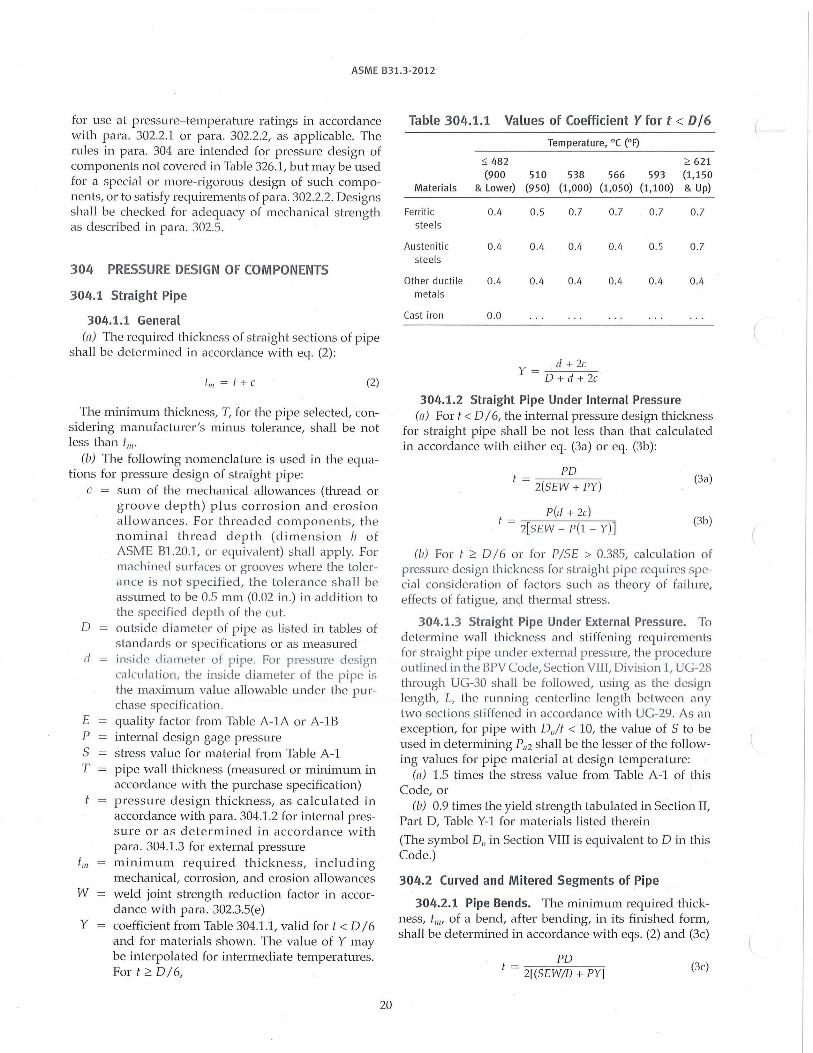
for use at pressure- temperature ratings in accordance with para. 302.2.l or para. 302.2.2, as applicable. The rules in para. 304 are intended for pressure design of components not covered in Table 326.1, but may be used for a special or more-rigorous design of such components, or to sa tisfy requirements of para. 302.2.2. Designs shall be checked for adequacy of mechanical sh·ength as described in para. 302.5.
304 PRESSURE DESIGN OF COMPONENTS
304.1 Straight Pipe
304.1.1 General (n) The required thickness of straight sections of pipe
shall be determined in accordance with eq. (2):
ti/I = t + c (2)
The minimum thickness, T, for the pipe selected, considering manufacturer 's minus tolerance, shall be not less than t111 •
(b) The following nomenclature is used in the equations for pressure design of sh·aight pipe:
c = sum of the mechanical allowances (thread or groove depth) plus corrosion and erosion a llowances . For threaded components, the nominal thread d epth (dimension /1 of ASME Bl.20.1, or equivalent) shall apply. For machined surfaces or grooves where the tolerance is not specified, the tolerance sh a ll be assumed to be 0.5 mm (0.02 in.) in addi tion to the specified depth of the cut.
D outside diameter of p ipe as lis ted in tables of s tandards or specifica tions or as measured
d inside diameter of pipe. For pressure design calcula tion, the inside d iameter of the pipe is the maxinrnm value allowable under the purchase specification.
E quality factor from Table A-lA or A-lB P internal design gage pressure S stress value for material from Table A-1 T pipe wall thickness (measured or minimum in
accordance with the purchase specification) pressure design thickness, as calculated in accordance with para. 304.1.2 for internal pressure or as determined in accordance w i th para. 304.1.3 for external pressure
t111 minimum required thickness, including mechanical, corrosion, and erosion allowances
W weld joint strength reduction factor in accordance with para. 302.3.5(e)
Y coefficient from Table 304.1.i, valid fort< D/6 and for materials shown. The value of Y may be interpolated for intermediate temperatures. Fort;:::: D/6,
20
Table 304.1.1 Values of Coefficient Y for t < DI 6
Temperature, °C (0 F)
~ 482 2 621 (900 510 538 566 593 (1,150
Materials & Lower) (950) (1,000) (1,050) (1, 100) & Up)
Ferrit ic 0.4 0.5 0.7 0.7 0.7 0. 7 steels
Austenitic 0.4 0.4 0.4 0.4 0.5 0.7 steels
Other ductile 0.4 0.4 0.4 0.4 0.4 0.4 metals
Cast iron 0.0
d + 2c y = -D-+----,d_+_2_c
304.1.2 Straight Pipe Under Internal Pressure (n) For t < D / 6, the internal pressure design thickness
for straight pipe shall be not less than that calculated in accordance with either eq. (3a) or eq. (3b):
PD ! -----~
- 2(SEW +PY) (3a)
P(d + 2c) t = 2~[ S_E_W ___ p(~l -_ -y"')] (3b)
(b) For t ;:::: O / 6 or for P/SE > 0.385, calculation of pressure design thickness for sh·aight pipe requires special consideration of factors such as theory of failure, effects of fatig ue, and thermal stress.
304.1.3 Straight Pipe Under External Pressure. To determine wall thickness and stiffening requirements for s traight pipe under ex ternal pressure, the procedure outlined in the BPV Code, Section VIII, Division 1, UG-28 through UG-30 shall be followed, using as the design length, L, the running centerline length between any two sections stiffened in accordance with UG-29. As an exception, for pipe with D0 /t < 10, the value of S to be used in determining Pa2 shall be the lesser of the following values for pipe material at design temperature:
(n) 1.5 times the stress value from Table A-1 of this Code, or
(b) 0.9 times the yield sh·ength tabulated in Section It Part D, Table Y-1 for materials listed therein
(The symbol D0 in Section VIII is equivalent to Din this Code.)
304.2 Curved and Mitered Segments of Pipe
304.2.1 Pipe Bends. The minimum required thickness, t1111 of a bend, after bending, in its finished form, shall be de termined in accordance with eqs. (2) and (3c)
PD t = 2[(SEW/J) +PY] (3c)
ASME 831.3-2012
Fig. 304.2.1 Nomenclature for Pipe Bends
I I I I I I R,
lntrados~
I I
Extrados
where at the intrados (inside bend radius)
I = 4(R1/ D) - 1 4(Ri/D) - 2
and at the extrados (outside bend radius)
I = 4(R1 /D) + 1 4(Ri/D) + 2
(3d)
(3e)
and at the sidewall on the bend centerline radius, I = 1.0, and where
R1 = bend radius of welding elbow or pipe bend
Thickness variations from the intra.dos to the extrados and along the length of the bend shall be gradual. The thickness requirements apply at the mid-span of the bend, 'Y /2, at the intrados, exh·ados, and bend centerline radius. The min imum thickness at the end tan gents shall not be less than the requirements of para . 304.1 for s tra ight pipe (see Fig. 304.2.1).
304.2.2 Elbows. Manufac tured elbows not in accordance with para . 303 shall be qualified as required by para. 304.7.2 o r d esign ed in accor d a nce with para. 304.2.l, except as provided in para . 328.4.2(b)(6).
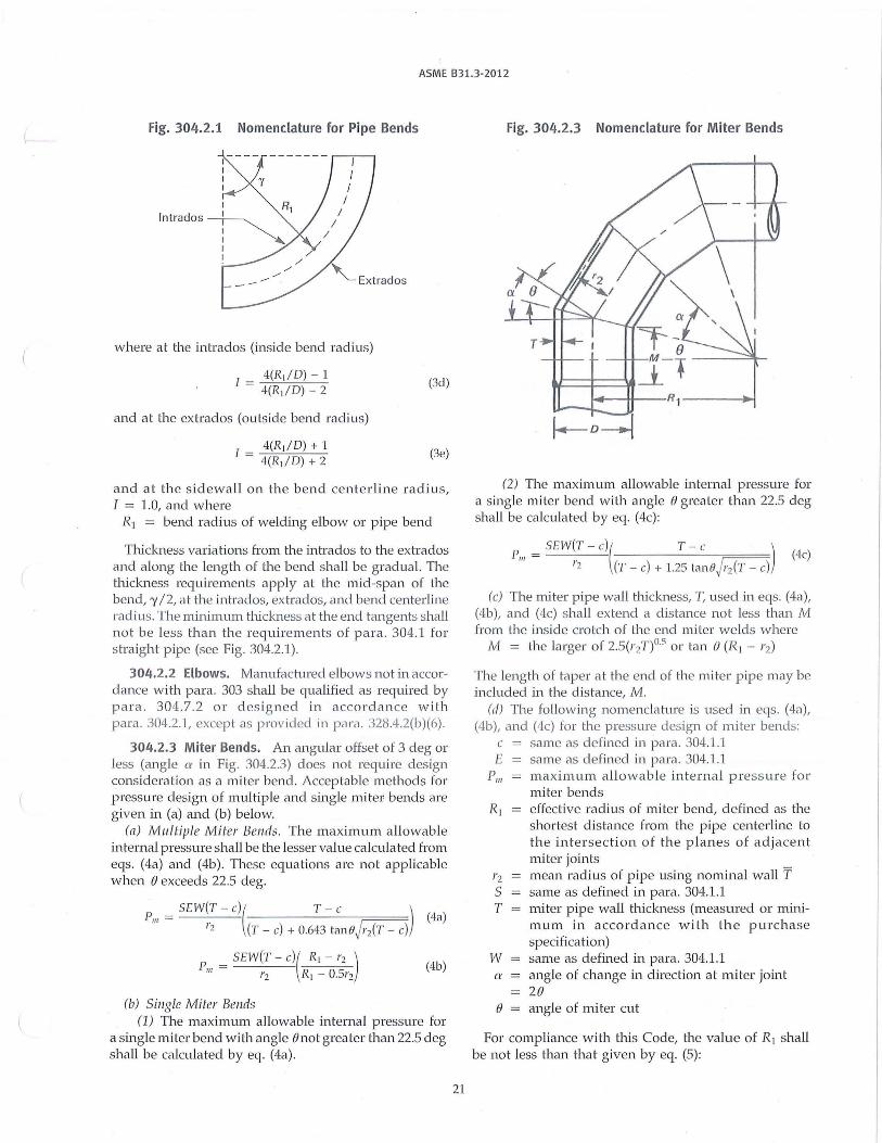
304.2.3 Miter Bends. An angular offset of 3 deg or less (angle er in Fig. 304.2.3) does not requi re design consideration as a nciter bend. Acceptable methods for pressure design of multiple and single miter bends are given in (a) and (b) below.
(n) Multiple Miter Bends. The maximum allowable internal press1ue shall be the lesser value calculated from eqs. (4a) and (4b). These equations are not applicable when e exceeds 22.5 deg.
p _ SEW(T - c)( T - c ) (4a) 111
- l'z (T - c) + 0.643 tan0J r2(T - c)
_ SEW(T - c)( R1 - r2 ) Pm - _ ___:. _ __;_, ---r2 R1 - 0.5r2
(4b)
(b) Single Miter Bends (1) The maximum allowable internal pressme for
a single miter bend with angle 8not grea ter than 22.5 deg shall be calculated by eq. (4a).
21
Fig. 304.2.3 Nomenclature for Miter Bends
i-..-~--R1 -----1~ u.---.L.-
(2) The maximum allowable internal pressure for a single miter bend wi th angle e greater than 22.5 deg shall be calculated by eq. (4c):
P111 = _ ___:. _ __;_, -------=== SEW(T - c)( T - c )
r2 (T - c) + 1.25 tanoJ r2(T - c) (4c)
(c) The miter pipe wall thickness, T, used in eqs. (4a), (4b), and (4c) shall extend a dis tance not less than M from the inside crotch of the end miter welds where
M = the larger of 2.5(r 2T)05 or tan e (R1 - r2)
The length of taper a t the end of the miter p ipe may be included in the dis tance, M.
(d) The fo llowing nomencla tme is used in eqs. (4a), (4b), and (4c) for the pressure design of miter bends:
c same as defined in para. 304.l .1 E same as defined in para. 304.1.1
P111 maximum allowable internal press ure fo r miter bends
R1 effective radius of miter bend, defined as the shortes t distance from the pipe centerline to the intersection of the planes of adjacent miter joints
r2 mean radius of pipe using nominal wall T S same as defined in para. 304.1.l T miter pipe wall thickness (measured or mini
mum in accordance with th e purchase specification)
W same as defined in para. 304.1.1 a angle of change in direc tion at miter joint
28 e angle of miter cut
For compliance with this Code, the value of Rt shall be not less than that given by eq. (5):