Embed Size (px)
Citation preview
Page | 24
CHROMLINE
Via Anita Garibaldi,40 59100 Prato (PO) – Italy
Phone: +39 335 1890076 Fax: +39 0574 660136 Email: [email protected] web: www.chromlinesrl.com
©2010 CHROMLINE SRL. Printed in Italy. Ver.1.6
Page | 1
Manual
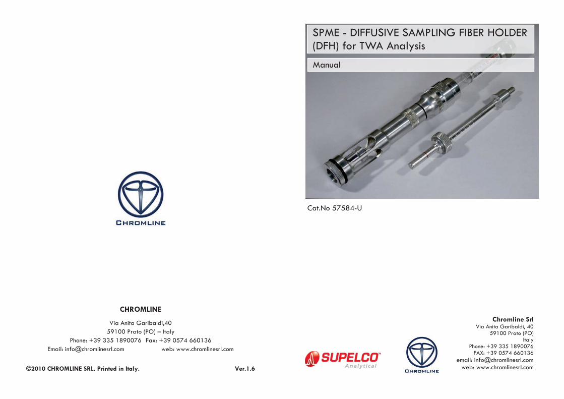
SPME - DIFFUSIVE SAMPLING FIBER HOLDER (DFH) for TWA Analysis
Chromline Srl Via Anita Garibaldi, 40
59100 Prato (PO) Italy
Phone: +39 335 1890076 FAX: +39 0574 660136
email: [email protected] web: www.chromlinesrl.com
Cat.No 57584-U
Page | 2
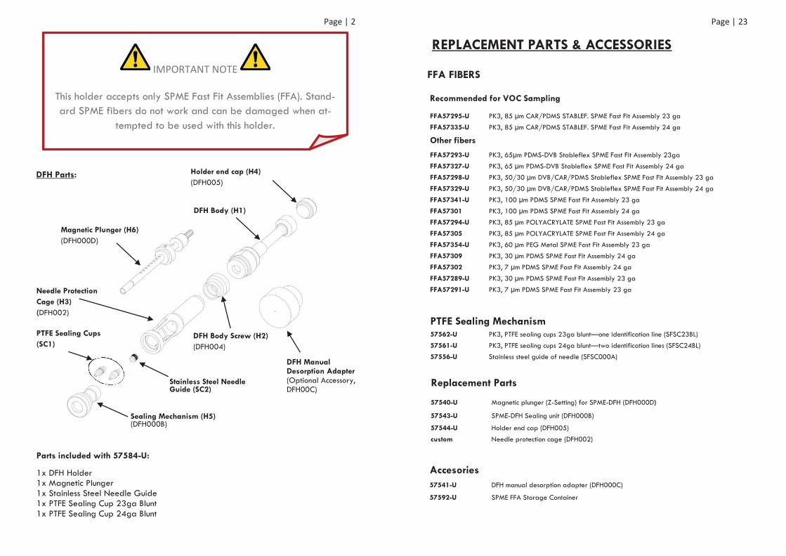
IMPORTANT NOTE
This holder accepts only SPME Fast Fit Assemblies (FFA). Stand-ard SPME fibers do not work and can be damaged when at-
tempted to be used with this holder.
Parts included with 57584-U:
1x DFH Holder 1x Magnetic Plunger 1x Stainless Steel Needle Guide 1x PTFE Sealing Cup 23ga Blunt 1x PTFE Sealing Cup 24ga Blunt
Sealing Mechanism (H5) (DFH000B)
PTFE Sealing Cups (SC1)
Stainless Steel Needle Guide (SC2)
DFH Manual Desorption Adapter (Optional Accessory, DFH00C)
Magnetic Plunger (H6) (DFH000D)
Holder end cap (H4)(DFH005)
DFH Body (H1)
DFH Body Screw (H2) (DFH004)
Needle Protection Cage (H3)(DFH002)
DFH Parts:
Page | 23
REPLACEMENT PARTS & ACCESSORIES
FFA FIBERS
Recommended for VOC Sampling
FFA57295-U PK3, 85 μm CAR/PDMS STABLEF. SPME Fast Fit Assembly 23 ga FFA57335-U PK3, 85 μm CAR/PDMS STABLEF. SPME Fast Fit Assembly 24 ga
Other fibers
FFA57293-U PK3, 65μm PDMS-DVB Stableflex SPME Fast Fit Assembly 23ga FFA57327-U PK3, 65 μm PDMS-DVB Stableflex SPME Fast Fit Assembly 24 ga FFA57298-U PK3, 50/30 μm DVB/CAR/PDMS Stableflex SPME Fast Fit Assembly 23 ga FFA57329-U PK3, 50/30 μm DVB/CAR/PDMS Stableflex SPME Fast Fit Assembly 24 ga
FFA57341-U PK3, 100 μm PDMS SPME Fast Fit Assembly 23 ga FFA57301 PK3, 100 μm PDMS SPME Fast Fit Assembly 24 ga FFA57294-U PK3, 85 μm POLYACRYLATE SPME Fast Fit Assembly 23 ga FFA57305 PK3, 85 μm POLYACRYLATE SPME Fast Fit Assembly 24 ga FFA57354-U PK3, 60 μm PEG Metal SPME Fast Fit Assembly 23 ga FFA57309 PK3, 30 μm PDMS SPME Fast Fit Assembly 24 ga FFA57302 PK3, 7 μm PDMS SPME Fast Fit Assembly 24 ga
FFA57289-U PK3, 30 μm PDMS SPME Fast Fit Assembly 23 ga FFA57291-U PK3, 7 μm PDMS SPME Fast Fit Assembly 23 ga
PTFE Sealing Mechanism 57562-U PK3, PTFE sealing cups 23ga blunt—one identification line (SFSC23BL) 57561-U PK3, PTFE sealing cups 24ga blunt—two identification lines (SFSC24BL)
57556-U Stainless steel guide of needle (SFSC000A)
Replacement Parts
57540-U Magnetic plunger (Z-Setting) for SPME-DFH (DFH000D)
57543-U SPME-DFH Sealing unit (DFH000B)
57544-U Holder end cap (DFH005)
custom Needle protection cage (DFH002)
Accesories 57541-U DFH manual desorption adapter (DFH000C)
57592-U SPME FFA Storage Container
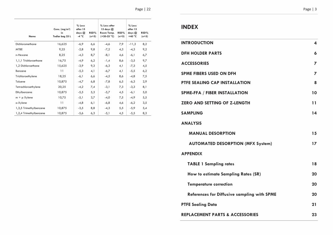
Page | 22
Name
Conc. (mg/m3) in
Tedlar bag 25 L
% Loss after 15 days @
-4 °C RSD% (n=5)
% Loss after 15 days @
Room Temp.(+20-25 °C)
RSD% (n=5)
% Loss after 15 days @ +40 °C
RSD% (n=5)
Dichloromethane 16,625 -6,9 6,6 -4,6 7,9 -11,3 8,2
MTBE 9,25 -2,8 9,8 -7,2 4,3 -4,3 9,2
n-Hexane 8,25 -4,3 8,7 -8,1 4,6 -6,1 6,7
1,1,1 Trichloroethane 16,75 -4,9 6,2 -1,4 8,6 -3,5 9,7
1,2 Dichloroethane 15,625 -3,9 9,3 -6,3 4,1 -7,3 4,5
Benzene 11 -5,3 4,1 -6,7 4,1 -5,5 6,2
Trichloroethylene 18,25 -6,1 6,6 -4,5 8,6 -4,8 7,5
Toluene 10,875 -4,7 6,8 -7,8 6,5 -6,3 2,9
Tetrachloroethylene 20,25 -4,2 7,4 -3,1 7,3 -3,3 8,1
Ethylbenzene 10,875 -5,5 5,3 -5,7 4,5 -6,1 5,0
m + p Xylene 10,75 -5,1 3,7 -4,0 7,5 -4,9 5,5
o-Xylene 11 -4,8 6,1 -6,8 4,6 -6,2 3,5
1,3,5 Trimethylbenzene 10,875 -3,5 8,8 -4,3 5,5 -5,9 5,4
1,2,4 Trimethylbenzene 10,875 -5,6 6,3 -5,1 4,5 -5,5 8,3
Page | 3
INDEX
INTRODUCTION 4
DFH HOLDER PARTS 6
ACCESSORIES 7
SPME FIBERS USED ON DFH 7
PTFE SEALING CAP INSTALLATION 8
SPME-FFA / FIBER INSTALLATION 10
ZERO AND SETTING OF Z-LENGTH 11
SAMPLING 14
ANALYSIS
MANUAL DESORPTION 15
AUTOMATED DESORPTION (MFX System) 17
APPENDIX
TABLE 1 Sampling rates 18
How to estimate Sampling Rates (SR) 20
Temperature correction 20
References for Diffusive sampling with SPME 20
PTFE Sealing Data 21
REPLACEMENT PARTS & ACCESSORIES 23
Page | 4
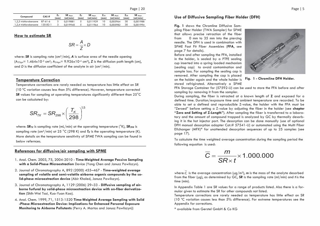
DIFFUSIVE SAMPLING FIBER HOLDER (DFH) Introduction
A DFH holder installed with a FFA is capable of determining time-weighted avera-ge (TWA) concentration of volatile organic compounds (VOCs) in air. Unlike con-ventional sampling with SPME, in which a fiber is extended outside its needle, during TWA passive sampling the fiber is retracted a known distance into its need-le. The DFH SPME passive sampler collects the VOCs by the mechanism of molecular diffusion and sorption on to the fiber.
Fig. 1. Schematic of analyte molecular diffusion and sorption on to a fiber.
This process is described with Fick’s first law of diffusion, whereby determination of the amounts of analytes accumulated over time enables measurement of the TWA concentration to which the sampler was exposed.
where is TWA concentration, m is analyte mass adsorbed, SR is sampling rate (which can be found/estimated in the Appendix in this manual) t is sampling time (e.g.15 min or 8 h).
TWA passive sampling with a SPME device has been shown to be almost indepen-dent of air flow rate, and to be more tolerant of high and low analyte concentrati-ons and long and short sampling times, because of the ease with which the diffusion path length could be changed. Environmental conditions, e.g. temperature, pressure, relative humidity, and ozone, have little or no effect on sampling. For more details please refer to the references listed in the Appendix (page 10).
tSRmC
_ C
Diffusion distance Z SPME fiber
Piercing/protection needle Fiber Plunger Analyte molecules
©2010 Chromline Srl
Page | 21
The Chromline sealing mechanism ensures integrity of fiber conditioning as well as storage of sampled fiber. Below chromatograms show a cleaned fiber immediately desorbed and after conditioning (Fig. 56) and after15 days sealed with the PTFE Sealing Cap used in the DFH (Fig. 57). The sealed fibers were exposed to the at-mosphere below mentioned compounds and concentrations. No contamination could be observed in that time. With the same test set up the storage stability of a sample was evaluated for the same mix of VOCs at different tempratures was evaluated. Temperatures was -4 °C, room temperature (+20-25 °C) and +40 °C. The test was done with 85μm CAR/PDMS 23ga fiber (the same fibers were used for each temperature). For sam-pling the fibers were exposed 15 sec to the atmosphere of compounds mentioned in below table. For details on this study please contact Chromline under [email protected].
Fig. 56 - Fiber after conditioning.
Fig. 57 - Fiber 15 days into Chromline PTFE sealing cup.
PTFE SEALING DATA
Page | 20
Compound CAS # Z3 (mm)
SR theor. (ml/min)
Z5 (mm)
SR theor. (ml/min)
Z10 (mm)
SR theor. (ml/min)
Z30 (mm)
SR theor. (ml/min)
1,2,3 trichlorobenzene 87-61-6 3 0,019881 5 0,011929 10 0,005964 30 0,001988 1,2,4 trichlorobenzene 120-82-1 3 0,019940 5 0,011964 10 0,005982 30 0,001994
Temperature Correction Temperature corrections are rarely needed as temperature has little effect on SR (10 ºC variation causes less than 5% difference). However, temperature corrected SR values for sampling at operating temperatures significantly different than 25°C can be calculated by:
where: SRTX is sampling rate (mL/min) at the operating temperature (°K), SR298 is sampling rate (cm3/min) at 25 °C (298 K) and TK is the operating temperature (K). More details on the temperature sensitivity of SPME TWA sampling can be found in below refernces.
References for diffusive/air sampling with SPME 1. Anal. Chem. 2003, 75, 2004-2010 - Time-Weighted Average Passive Sampling
with a Solid-Phase Microextraction Device (Yong Chen and Janusz Pawliszyn).
2. Journal of Chromatography A, 892 (2000) 455–467 - Time-weighted average sampling of volatile and semi-volatile airborne organic compounds by the so-lid-phase microextraction device (Abir Khaled, Janusz Pawliszyn).
3. Journal of Chromatography A, 1129 (2006) 29–33 - Diffusive sampling of air-borne furfural by solid-phase microextraction device with on-fiber derivatiza-tion (Shih-Wei Tsai, Kuo-Yuan Kao).
4. Anal. Chem. 1999, 71, 1513-1520 Time-Weighted Average Sampling with Solid-Phase Microextraction Device: Implications for Enhanced Personal Exposure Monitoring to Airborne Pollutants (Perry A. Martos and Janusz Pawliszyn))
How to estimate SR
where: SR is sampling rate (cm3/min), A is surface area of the needle opening (A23ga= 1.464x10⁻³ cm2; A24ga= 9.926x10⁻⁴ cm2), Z is the diffusion path length (cm), and D is the diffusion coefficient of the analyte in air (cm2/min).
DZASR
5,1
298 298K
TXTSRSR
Page | 5
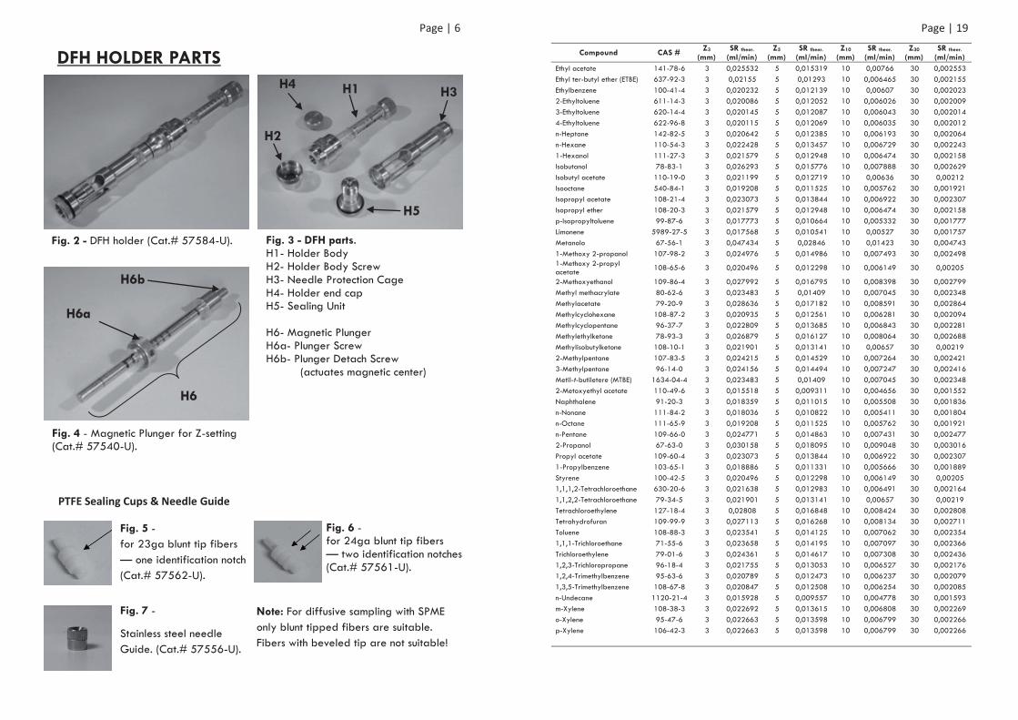
Use of Diffusive Sampling Fiber Holder (DFH) Fig. 1 shows the Chromline Diffusive Sam-pling Fiber Holder (TWA Sampler) for SPME that allows precise retraction of the fiber from 0 mm to 35 mm into the piercing needle. The DFH is used in combination with SPME Fast Fit Fiber Assembies (FFA, see page 7 for details). Before and after sampling the FFA, installed in the holder, is sealed by a PTFE sealing cup inserted into a spring loaded mechanism (sealing cap) to avoid contamination and sample loss. For sampling the sealing cap is removed. After sampling the cap is placed on the holder again and the whole holder is stored refrigirated. Alternatively a SPME FFA Storage Container for (57592-U) can be used to store the FFA before and after sampling by removing it from the sampler. During sampling, the fiber is retracted at a known length of Z and exposed for a defined time. Duration/exposure time and ambient temperature are recorded. To be able to set a defined and reproducible Z-value, the holder with the FFA must be “Zeroed” before setting a Z-value by adjusting the fiber in the holder (see chapter “Zero and Setting of Z-Length”). After sampling the fiber is transferred to a labora-tory and the amount of compound trapped is analyzed by GC by thermally desorb-ing it in the hot injector port. The desorption can be done manually (use of optional DFH manual desorption adapter Cat.# 57541-U) or automated using the Multi Fiber EXchanger (MFX)* for unattended desorption sequences of up to 25 samples (see page 17).
To calculate the time weighted average concentration during the sampling period the following equation is used:
where: is the average concentration (μg/m3), m is the mass of the analyte desorbed from the fiber (μg), as determined by GC, SR is the sampling rate (ml/min) and t is the time (min).
In Appendix Table 1 are SR values for a range of products listed. Also there is a for-mular given to estimate the SR for other compounds not listed. Temperature corrections are rarely needed as temperature has little effect on SR (10 ºC variation causes less than 5% difference). For extreme temperatures see the Appendix for corrections.
Fig. 1 - Chromline DFH Holder.
000.000.1tSR
mC
_ C
* available from Gerstel GmbH & Co KG
Page | 6
DFH HOLDER PARTS
Fig. 2 - DFH holder (Cat.# 57584-U). Fig. 3 - DFH parts. H1- Holder Body H2- Holder Body Screw H3- Needle Protection Cage H4- Holder end cap H5- Sealing Unit H6- Magnetic Plunger H6a- Plunger Screw H6b- Plunger Detach Screw (actuates magnetic center)
H1 H3 H4
H2
H5
Fig. 4 - Magnetic Plunger for Z-setting (Cat.# 57540-U).
H6
H6a
H6b
Fig. 5 - for 23ga blunt tip fibers — one identification notch (Cat.# 57562-U).
Fig. 6 - for 24ga blunt tip fibers — two identification notches (Cat.# 57561-U).
Fig. 7 -
Stainless steel needle Guide. (Cat.# 57556-U).
PTFE Sealing Cups & Needle Guide
Note: For diffusive sampling with SPME only blunt tipped fibers are suitable. Fibers with beveled tip are not suitable!
Page | 19
Compound CAS # Z3 (mm)
SR theor. (ml/min)
Z5 (mm)
SR theor. (ml/min)
Z10 (mm)
SR theor. (ml/min)
Z30 (mm)
SR theor. (ml/min)
Ethyl acetate 141-78-6 3 0,025532 5 0,015319 10 0,00766 30 0,002553 Ethyl ter-butyl ether (ETBE) 637-92-3 3 0,02155 5 0,01293 10 0,006465 30 0,002155 Ethylbenzene 100-41-4 3 0,020232 5 0,012139 10 0,00607 30 0,002023 2-Ethyltoluene 611-14-3 3 0,020086 5 0,012052 10 0,006026 30 0,002009 3-Ethyltoluene 620-14-4 3 0,020145 5 0,012087 10 0,006043 30 0,002014 4-Ethyltoluene 622-96-8 3 0,020115 5 0,012069 10 0,006035 30 0,002012 n-Heptane 142-82-5 3 0,020642 5 0,012385 10 0,006193 30 0,002064 n-Hexane 110-54-3 3 0,022428 5 0,013457 10 0,006729 30 0,002243 1-Hexanol 111-27-3 3 0,021579 5 0,012948 10 0,006474 30 0,002158 Isobutanol 78-83-1 3 0,026293 5 0,015776 10 0,007888 30 0,002629 Isobutyl acetate 110-19-0 3 0,021199 5 0,012719 10 0,00636 30 0,00212 Isooctane 540-84-1 3 0,019208 5 0,011525 10 0,005762 30 0,001921 Isopropyl acetate 108-21-4 3 0,023073 5 0,013844 10 0,006922 30 0,002307 Isopropyl ether 108-20-3 3 0,021579 5 0,012948 10 0,006474 30 0,002158 p-Isopropyltoluene 99-87-6 3 0,017773 5 0,010664 10 0,005332 30 0,001777 Limonene 5989-27-5 3 0,017568 5 0,010541 10 0,00527 30 0,001757 Metanolo 67-56-1 3 0,047434 5 0,02846 10 0,01423 30 0,004743 1-Methoxy 2-propanol 107-98-2 3 0,024976 5 0,014986 10 0,007493 30 0,002498 1-Methoxy 2-propyl acetate 108-65-6 3 0,020496 5 0,012298 10 0,006149 30 0,00205
2-Methoxyethanol 109-86-4 3 0,027992 5 0,016795 10 0,008398 30 0,002799 Methyl methacrylate 80-62-6 3 0,023483 5 0,01409 10 0,007045 30 0,002348 Methylacetate 79-20-9 3 0,028636 5 0,017182 10 0,008591 30 0,002864 Methylcyclohexane 108-87-2 3 0,020935 5 0,012561 10 0,006281 30 0,002094 Methylcyclopentane 96-37-7 3 0,022809 5 0,013685 10 0,006843 30 0,002281 Methylethylketone 78-93-3 3 0,026879 5 0,016127 10 0,008064 30 0,002688 Methylisobutylketone 108-10-1 3 0,021901 5 0,013141 10 0,00657 30 0,00219 2-Methylpentane 107-83-5 3 0,024215 5 0,014529 10 0,007264 30 0,002421 3-Methylpentane 96-14-0 3 0,024156 5 0,014494 10 0,007247 30 0,002416 Metil-t-butiletere (MTBE) 1634-04-4 3 0,023483 5 0,01409 10 0,007045 30 0,002348 2-Metoxyethyl acetate 110-49-6 3 0,015518 5 0,009311 10 0,004656 30 0,001552 Naphthalene 91-20-3 3 0,018359 5 0,011015 10 0,005508 30 0,001836 n-Nonane 111-84-2 3 0,018036 5 0,010822 10 0,005411 30 0,001804 n-Octane 111-65-9 3 0,019208 5 0,011525 10 0,005762 30 0,001921 n-Pentane 109-66-0 3 0,024771 5 0,014863 10 0,007431 30 0,002477 2-Propanol 67-63-0 3 0,030158 5 0,018095 10 0,009048 30 0,003016 Propyl acetate 109-60-4 3 0,023073 5 0,013844 10 0,006922 30 0,002307 1-Propylbenzene 103-65-1 3 0,018886 5 0,011331 10 0,005666 30 0,001889 Styrene 100-42-5 3 0,020496 5 0,012298 10 0,006149 30 0,00205 1,1,1,2-Tetrachloroethane 630-20-6 3 0,021638 5 0,012983 10 0,006491 30 0,002164 1,1,2,2-Tetrachloroethane 79-34-5 3 0,021901 5 0,013141 10 0,00657 30 0,00219 Tetrachloroethylene 127-18-4 3 0,02808 5 0,016848 10 0,008424 30 0,002808 Tetrahydrofuran 109-99-9 3 0,027113 5 0,016268 10 0,008134 30 0,002711 Toluene 108-88-3 3 0,023541 5 0,014125 10 0,007062 30 0,002354 1,1,1-Trichloroethane 71-55-6 3 0,023658 5 0,014195 10 0,007097 30 0,002366 Trichloroethylene 79-01-6 3 0,024361 5 0,014617 10 0,007308 30 0,002436 1,2,3-Trichloropropane 96-18-4 3 0,021755 5 0,013053 10 0,006527 30 0,002176 1,2,4-Trimethylbenzene 95-63-6 3 0,020789 5 0,012473 10 0,006237 30 0,002079 1,3,5-Trimethylbenzene 108-67-8 3 0,020847 5 0,012508 10 0,006254 30 0,002085 n-Undecane 1120-21-4 3 0,015928 5 0,009557 10 0,004778 30 0,001593 m-Xylene 108-38-3 3 0,022692 5 0,013615 10 0,006808 30 0,002269 o-Xylene 95-47-6 3 0,022663 5 0,013598 10 0,006799 30 0,002266 p-Xylene 106-42-3 3 0,022663 5 0,013598 10 0,006799 30 0,002266
Page | 18
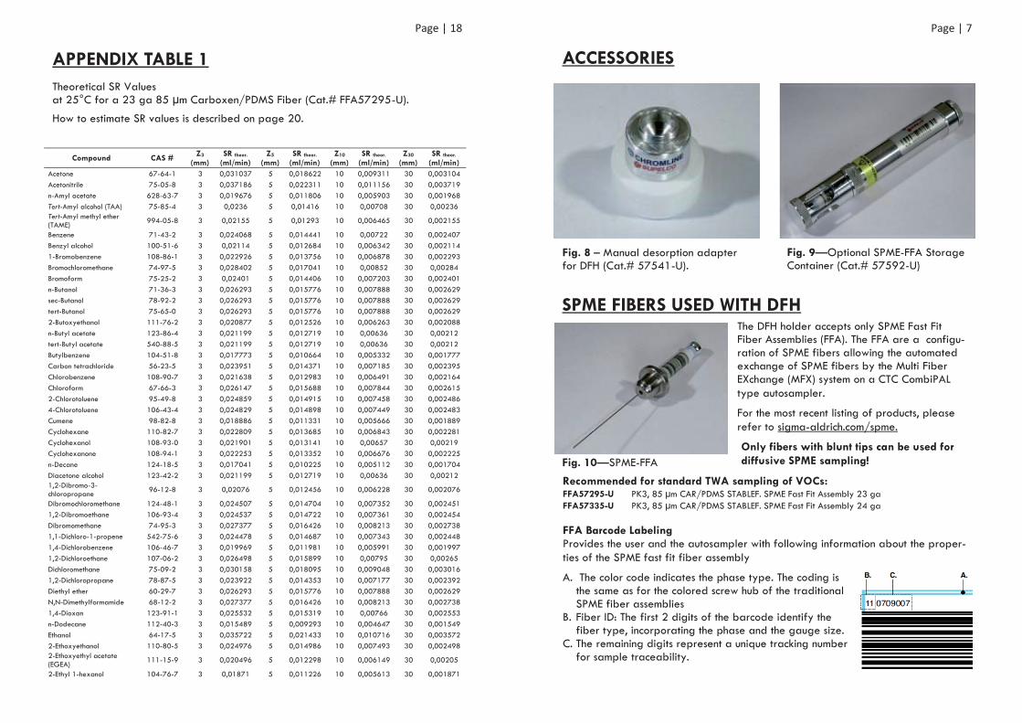
APPENDIX TABLE 1 Theoretical SR Values at 25°C for a 23 ga 85 μm Carboxen/PDMS Fiber (Cat.# FFA57295-U).
How to estimate SR values is described on page 20.
Acetone 67-64-1 3 0,031037 5 0,018622 10 0,009311 30 0,003104 Acetonitrile 75-05-8 3 0,037186 5 0,022311 10 0,011156 30 0,003719 n-Amyl acetate 628-63-7 3 0,019676 5 0,011806 10 0,005903 30 0,001968 Tert-Amyl alcohol (TAA) 75-85-4 3 0,0236 5 0,01416 10 0,00708 30 0,00236 Tert-Amyl methyl ether (TAME) 994-05-8 3 0,02155 5 0,01293 10 0,006465 30 0,002155
Benzene 71-43-2 3 0,024068 5 0,014441 10 0,00722 30 0,002407 Benzyl alcohol 100-51-6 3 0,02114 5 0,012684 10 0,006342 30 0,002114 1-Bromobenzene 108-86-1 3 0,022926 5 0,013756 10 0,006878 30 0,002293 Bromochloromethane 74-97-5 3 0,028402 5 0,017041 10 0,00852 30 0,00284 Bromoform 75-25-2 3 0,02401 5 0,014406 10 0,007203 30 0,002401 n-Butanol 71-36-3 3 0,026293 5 0,015776 10 0,007888 30 0,002629 sec-Butanol 78-92-2 3 0,026293 5 0,015776 10 0,007888 30 0,002629 tert-Butanol 75-65-0 3 0,026293 5 0,015776 10 0,007888 30 0,002629 2-Butoxyethanol 111-76-2 3 0,020877 5 0,012526 10 0,006263 30 0,002088 n-Butyl acetate 123-86-4 3 0,021199 5 0,012719 10 0,00636 30 0,00212 tert-Butyl acetate 540-88-5 3 0,021199 5 0,012719 10 0,00636 30 0,00212 Butylbenzene 104-51-8 3 0,017773 5 0,010664 10 0,005332 30 0,001777 Carbon tetrachloride 56-23-5 3 0,023951 5 0,014371 10 0,007185 30 0,002395 Chlorobenzene 108-90-7 3 0,021638 5 0,012983 10 0,006491 30 0,002164 Chloroform 67-66-3 3 0,026147 5 0,015688 10 0,007844 30 0,002615 2-Chlorotoluene 95-49-8 3 0,024859 5 0,014915 10 0,007458 30 0,002486 4-Chlorotoluene 106-43-4 3 0,024829 5 0,014898 10 0,007449 30 0,002483 Cumene 98-82-8 3 0,018886 5 0,011331 10 0,005666 30 0,001889 Cyclohexane 110-82-7 3 0,022809 5 0,013685 10 0,006843 30 0,002281 Cyclohexanol 108-93-0 3 0,021901 5 0,013141 10 0,00657 30 0,00219 Cyclohexanone 108-94-1 3 0,022253 5 0,013352 10 0,006676 30 0,002225 n-Decane 124-18-5 3 0,017041 5 0,010225 10 0,005112 30 0,001704 Diacetone alcohol 123-42-2 3 0,021199 5 0,012719 10 0,00636 30 0,00212 1,2-Dibromo-3-chloropropane 96-12-8 3 0,02076 5 0,012456 10 0,006228 30 0,002076
Dibromochloromethane 124-48-1 3 0,024507 5 0,014704 10 0,007352 30 0,002451 1,2-Dibromoethane 106-93-4 3 0,024537 5 0,014722 10 0,007361 30 0,002454 Dibromomethane 74-95-3 3 0,027377 5 0,016426 10 0,008213 30 0,002738 1,1-Dichloro-1-propene 542-75-6 3 0,024478 5 0,014687 10 0,007343 30 0,002448 1,4-Dichlorobenzene 106-46-7 3 0,019969 5 0,011981 10 0,005991 30 0,001997 1,2-Dichloroethane 107-06-2 3 0,026498 5 0,015899 10 0,00795 30 0,00265 Dichloromethane 75-09-2 3 0,030158 5 0,018095 10 0,009048 30 0,003016 1,2-Dichloropropane 78-87-5 3 0,023922 5 0,014353 10 0,007177 30 0,002392 Diethyl ether 60-29-7 3 0,026293 5 0,015776 10 0,007888 30 0,002629 N,N-Dimethylformamide 68-12-2 3 0,027377 5 0,016426 10 0,008213 30 0,002738 1,4-Dioxan 123-91-1 3 0,025532 5 0,015319 10 0,00766 30 0,002553 n-Dodecane 112-40-3 3 0,015489 5 0,009293 10 0,004647 30 0,001549 Ethanol 64-17-5 3 0,035722 5 0,021433 10 0,010716 30 0,003572 2-Ethoxyethanol 110-80-5 3 0,024976 5 0,014986 10 0,007493 30 0,002498 2-Ethoxyethyl acetate (EGEA) 111-15-9 3 0,020496 5 0,012298 10 0,006149 30 0,00205
2-Ethyl 1-hexanol 104-76-7 3 0,01871 5 0,011226 10 0,005613 30 0,001871
Compound CAS # Z3 (mm)
SR theor. (ml/min)
Z5 (mm)
SR theor. (ml/min)
Z10 (mm)
SR theor. (ml/min)
Z30 (mm)
SR theor. (ml/min)
Page | 7
ACCESSORIES
Fig. 8 – Manual desorption adapter for DFH (Cat.# 57541-U).
SPME FIBERS USED WITH DFH The DFH holder accepts only SPME Fast Fit Fiber Assemblies (FFA). The FFA are a configu-ration of SPME fibers allowing the automated exchange of SPME fibers by the Multi Fiber EXchange (MFX) system on a CTC CombiPAL type autosampler.
For the most recent listing of products, please refer to sigma-aldrich.com/spme.
Only fibers with blunt tips can be used for diffusive SPME sampling!
Recommended for standard TWA sampling of VOCs: FFA57295-U PK3, 85 μm CAR/PDMS STABLEF. SPME Fast Fit Assembly 23 ga FFA57335-U PK3, 85 μm CAR/PDMS STABLEF. SPME Fast Fit Assembly 24 ga FFA Barcode Labeling Provides the user and the autosampler with following information about the proper-ties of the SPME fast fit fiber assembly
A. The color code indicates the phase type. The coding is the same as for the colored screw hub of the traditional SPME fiber assemblies
B. Fiber ID: The first 2 digits of the barcode identify the fiber type, incorporating the phase and the gauge size.
C. The remaining digits represent a unique tracking number for sample traceability.
Fig. 9—Optional SPME-FFA Storage Container (Cat.# 57592-U)
Fig. 10—SPME-FFA
Page | 8
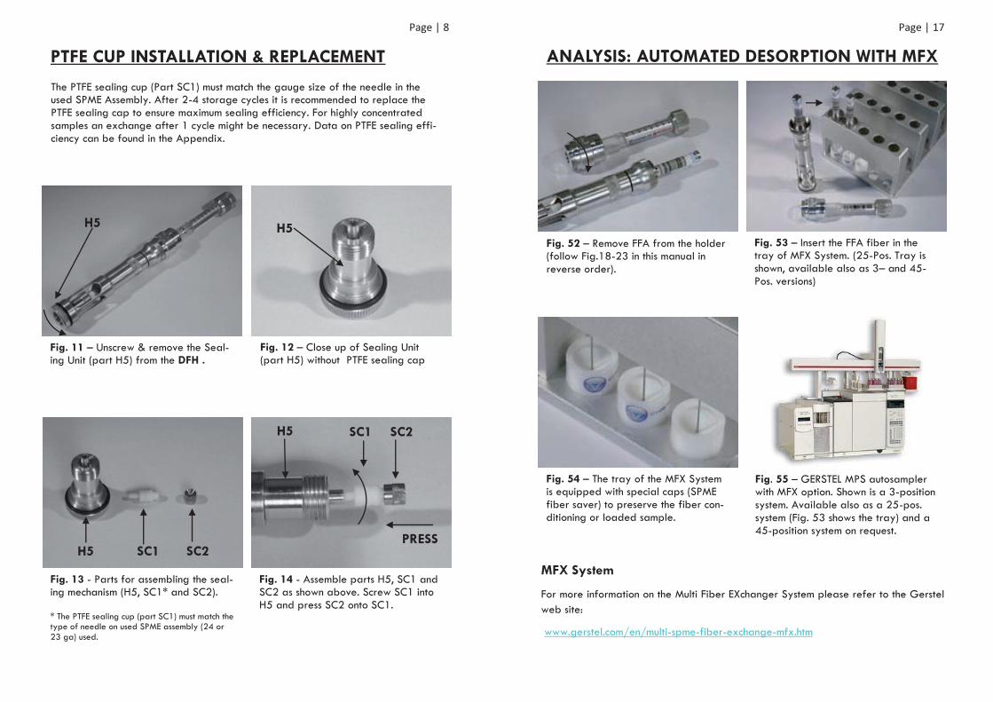
PTFE CUP INSTALLATION & REPLACEMENT
The PTFE sealing cup (Part SC1) must match the gauge size of the needle in the used SPME Assembly. After 2-4 storage cycles it is recommended to replace the PTFE sealing cap to ensure maximum sealing efficiency. For highly concentrated samples an exchange after 1 cycle might be necessary. Data on PTFE sealing effi-ciency can be found in the Appendix.
Fig. 11 – Unscrew & remove the Seal-ing Unit (part H5) from the DFH .
Fig. 12 – Close up of Sealing Unit (part H5) without PTFE sealing cap
H5 H5
H5 SC1 SC2 PRESS
H5 SC1 SC2
Fig. 13 - Parts for assembling the seal-ing mechanism (H5, SC1* and SC2). * The PTFE sealing cup (part SC1) must match the type of needle on used SPME assembly (24 or 23 ga) used.
Fig. 14 - Assemble parts H5, SC1 and SC2 as shown above. Screw SC1 into H5 and press SC2 onto SC1.
Page | 17
ANALYSIS: AUTOMATED DESORPTION WITH MFX
Fig. 52 – Remove FFA from the holder (follow Fig.18-23 in this manual in reverse order).
Fig. 53 – Insert the FFA fiber in the tray of MFX System. (25-Pos. Tray is shown, available also as 3– and 45-Pos. versions)
Fig. 54 – The tray of the MFX System is equipped with special caps (SPME fiber saver) to preserve the fiber con-ditioning or loaded sample.
Fig. 55 – GERSTEL MPS autosampler with MFX option. Shown is a 3-position system. Available also as a 25-pos. system (Fig. 53 shows the tray) and a 45-position system on request.
MFX System
For more information on the Multi Fiber EXchanger System please refer to the Gerstel web site:
www.gerstel.com/en/multi-spme-fiber-exchange-mfx.htm
Page | 16
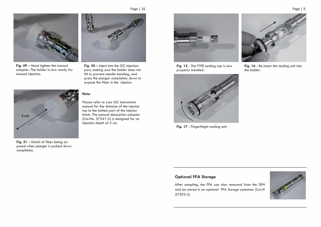
Fig. 51 – Detail of fiber being ex-posed when plunger is pushed down completely.
Fig. 49 – Hand tighten the manual adapter. The holder is now ready for manual injection.
Fig. 50 – Inject into the GC injection port, making sure the holder does not tilt to prevent needle bending, and press the plunger completely down to expose the fiber in the injector.
Note: Please refer to your GC instruments manual for the distance of the injector top to the hottest part of the injector block. The manual desorption adapter (Cat.No. 57541-U) is designed for an injection depth of 5 cm.
5 cm
Page | 9
Fig. 15 - The PTFE sealing cup is now properly installed.
Fig. 16 - Re-insert the sealing unit into the holder.
Fig. 17 - Fingerthight sealing unit.
Optional FFA Storage
After sampling, the FFA can also removed from the DFH and be stored in an optional FFA Sorage container (Cat.# 57592-U)
Page | 10
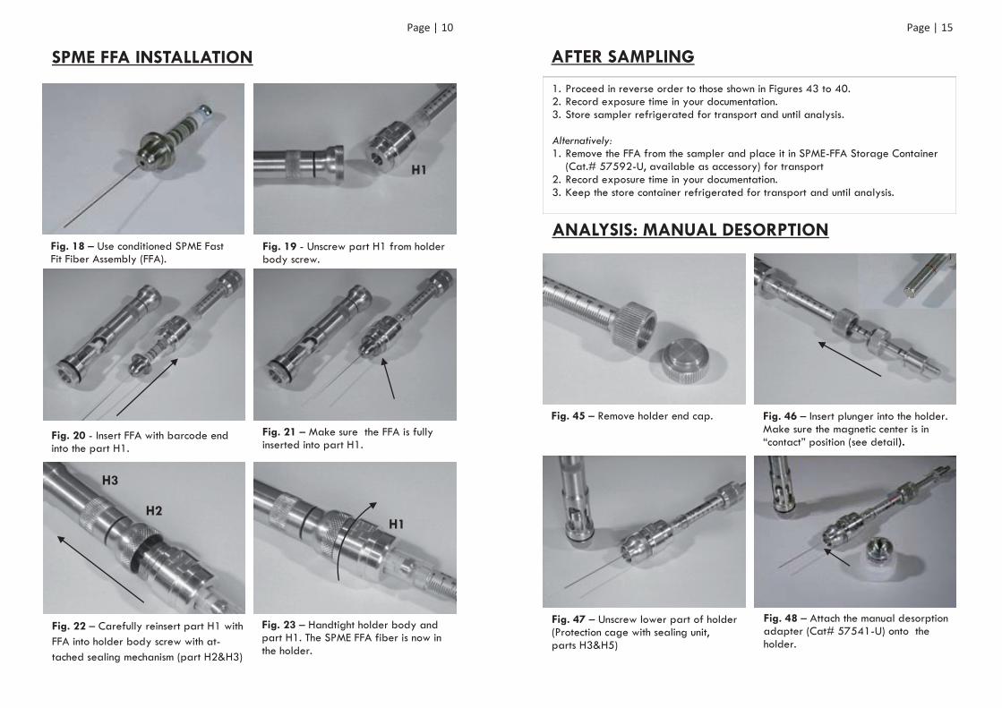
SPME FFA INSTALLATION
Fig. 18 – Use conditioned SPME Fast Fit Fiber Assembly (FFA).
Fig. 22 – Carefully reinsert part H1 with FFA into holder body screw with at-tached sealing mechanism (part H2&H3)
Fig. 23 – Handtight holder body and part H1. The SPME FFA fiber is now in the holder.
Fig. 20 - Insert FFA with barcode end into the part H1.
Fig. 21 – Make sure the FFA is fully inserted into part H1.
Fig. 19 - Unscrew part H1 from holder body screw.
H1
H2
H3
H1
Page | 15
1. Proceed in reverse order to those shown in Figures 43 to 40. 2. Record exposure time in your documentation. 3. Store sampler refrigerated for transport and until analysis. Alternatively: 1. Remove the FFA from the sampler and place it in SPME-FFA Storage Container
(Cat.# 57592-U, available as accessory) for transport 2. Record exposure time in your documentation. 3. Keep the store container refrigerated for transport and until analysis.
ANALYSIS: MANUAL DESORPTION
Fig. 45 – Remove holder end cap. Fig. 46 – Insert plunger into the holder. Make sure the magnetic center is in “contact” position (see detail).
Fig. 47 – Unscrew lower part of holder (Protection cage with sealing unit, parts H3&H5)
Fig. 48 – Attach the manual desorption adapter (Cat# 57541-U) onto the holder.
AFTER SAMPLING
Page | 14
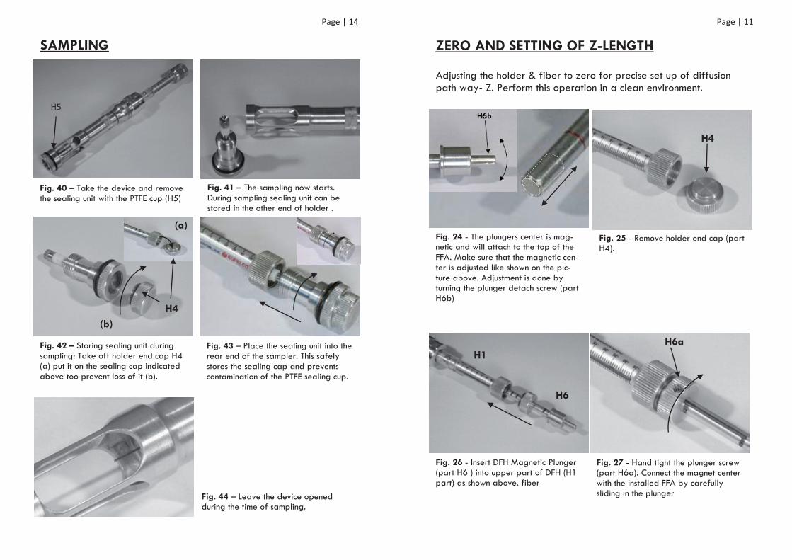
SAMPLING
Fig. 40 – Take the device and remove the sealing unit with the PTFE cup (H5)
Fig. 41 – The sampling now starts. During sampling sealing unit can be stored in the other end of holder .
H4
Fig. 42 – Storing sealing unit during sampling: Take off holder end cap H4 (a) put it on the sealing cap indicated above too prevent loss of it (b).
Fig. 43 – Place the sealing unit into the rear end of the sampler. This safely stores the sealing cap and prevents contamination of the PTFE sealing cup.
Fig. 44 – Leave the device opened during the time of sampling.
H5
(a)
(b)
Page | 11
ZERO AND SETTING OF Z-LENGTH
Adjusting the holder & fiber to zero for precise set up of diffusion path way- Z. Perform this operation in a clean environment.
H4
Fig. 25 - Remove holder end cap (part H4).
Fig. 24 - The plungers center is mag-netic and will attach to the top of the FFA. Make sure that the magnetic cen-ter is adjusted like shown on the pic-ture above. Adjustment is done by turning the plunger detach screw (part H6b)
H6
H1
Fig. 26 - Insert DFH Magnetic Plunger (part H6 ) into upper part of DFH (H1 part) as shown above. fiber
Fig. 27 - Hand tight the plunger screw (part H6a). Connect the magnet center with the installed FFA by carefully sliding in the plunger
H6a
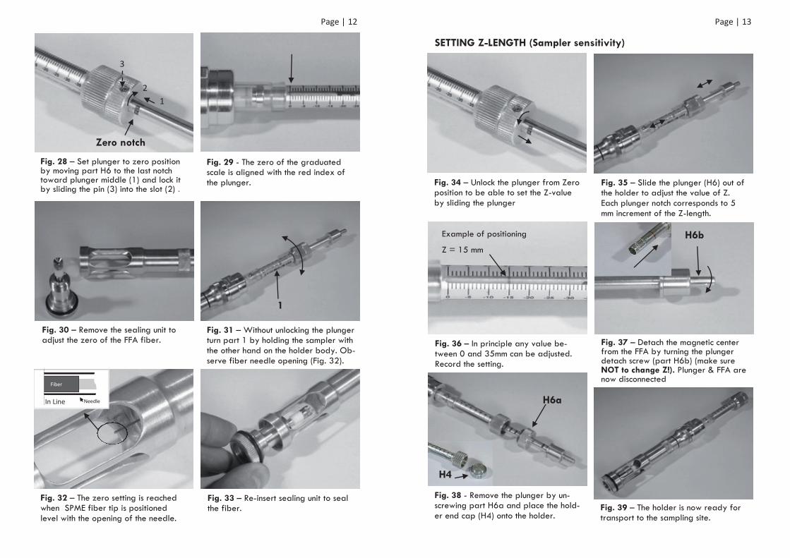
Page | 12
Zero notch
Fig. 28 – Set plunger to zero position by moving part H6 to the last notch toward plunger middle (1) and lock it by sliding the pin (3) into the slot (2) .
Fig. 29 - The zero of the graduated scale is aligned with the red index of the plunger.
1
Fig. 30 – Remove the sealing unit to adjust the zero of the FFA fiber.
Fig. 31 – Without unlocking the plunger turn part 1 by holding the sampler with the other hand on the holder body. Ob-serve fiber needle opening (Fig. 32).
Fig. 32 – The zero setting is reached when SPME fiber tip is positioned level with the opening of the needle.
Fig. 33 – Re-insert sealing unit to seal the fiber.
1 2
3
In Line
Fiber
Needle
Page | 13
SETTING Z-LENGTH (Sampler sensitivity)
Fig. 34 – Unlock the plunger from Zero position to be able to set the Z-value by sliding the plunger
Fig. 35 – Slide the plunger (H6) out of the holder to adjust the value of Z. Each plunger notch corresponds to 5 mm increment of the Z-length.
Fig. 36 – In principle any value be-tween 0 and 35mm can be adjusted. Record the setting.
Fig. 37 – Detach the magnetic center from the FFA by turning the plunger detach screw (part H6b) (make sure NOT to change Z!). Plunger & FFA are now disconnected
H6b
Fig. 38 - Remove the plunger by un-screwing part H6a and place the hold-er end cap (H4) onto the holder.
Fig. 39 – The holder is now ready for transport to the sampling site.
H6a
Example of positioning
Z = 15 mm
H4