Embed Size (px)
Citation preview
Page 3 of 17 Issued on 16.05.2013 Technical Circular No. RDSO/2013/EL/TC/0123,Rev‘0’
Annexure-I
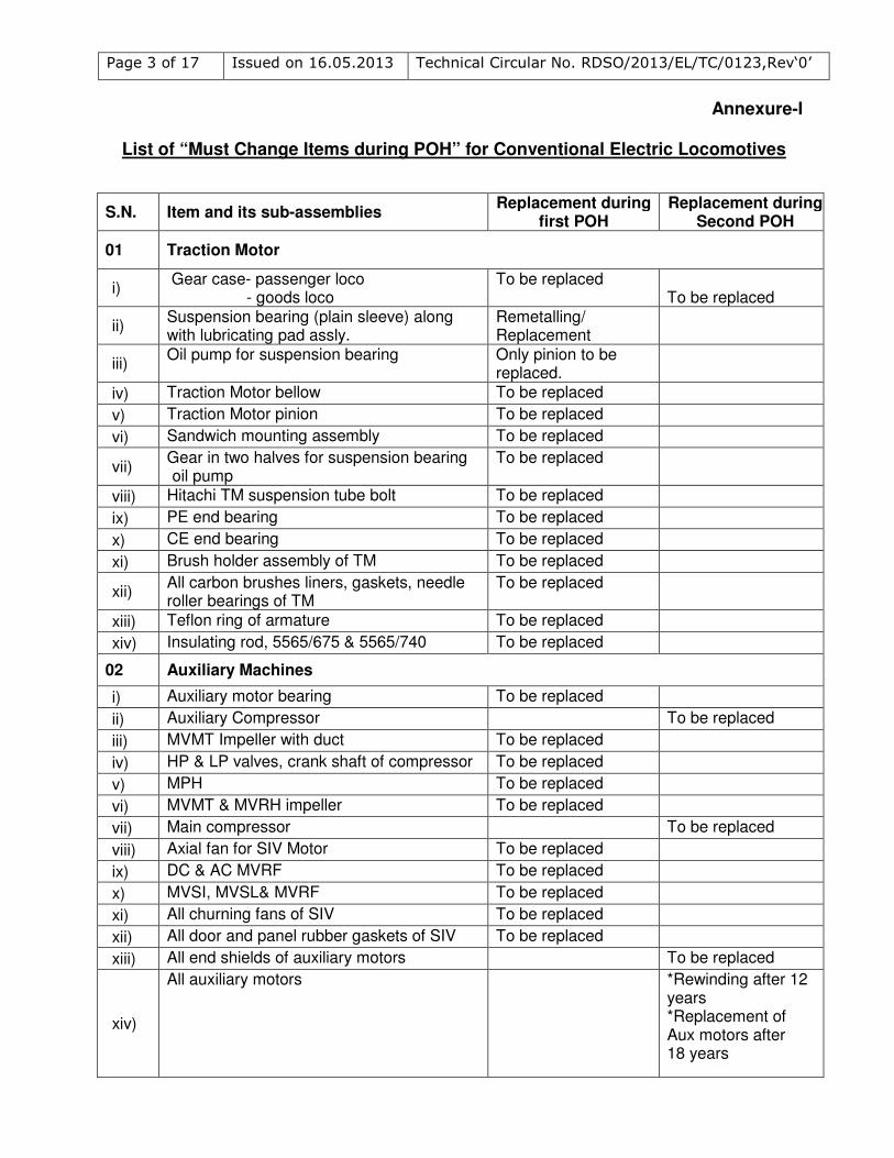
List of “Must Change Items during POH” for Conventional Electric Locomotives
S.N. Item and its sub-assemblies Replacement during
first POH Replacement during
Second POH
01 Traction Motor
i) Gear case- passenger loco - goods loco
To be replaced
To be replaced
ii) Suspension bearing (plain sleeve) along with lubricating pad assly.
Remetalling/ Replacement
iii) Oil pump for suspension bearing Only pinion to be
replaced.
iv) Traction Motor bellow To be replaced
v) Traction Motor pinion To be replaced
vi) Sandwich mounting assembly To be replaced
vii) Gear in two halves for suspension bearing oil pump
To be replaced
viii) Hitachi TM suspension tube bolt To be replaced
ix) PE end bearing To be replaced
x) CE end bearing To be replaced
xi) Brush holder assembly of TM To be replaced
xii) All carbon brushes liners, gaskets, needle roller bearings of TM
To be replaced
xiii) Teflon ring of armature To be replaced
xiv) Insulating rod, 5565/675 & 5565/740 To be replaced
02 Auxiliary Machines
i) Auxiliary motor bearing To be replaced
ii) Auxiliary Compressor To be replaced
iii) MVMT Impeller with duct To be replaced
iv) HP & LP valves, crank shaft of compressor To be replaced
v) MPH To be replaced
vi) MVMT & MVRH impeller To be replaced
vii) Main compressor To be replaced
viii) Axial fan for SIV Motor To be replaced
ix) DC & AC MVRF To be replaced
x) MVSI, MVSL& MVRF To be replaced
xi) All churning fans of SIV To be replaced
xii) All door and panel rubber gaskets of SIV To be replaced
xiii) All end shields of auxiliary motors To be replaced
xiv)
All auxiliary motors *Rewinding after 12 years *Replacement of Aux motors after 18 years
Page 4 of 17 Issued on 16.05.2013 Technical Circular No. RDSO/2013/EL/TC/0123,Rev‘0’
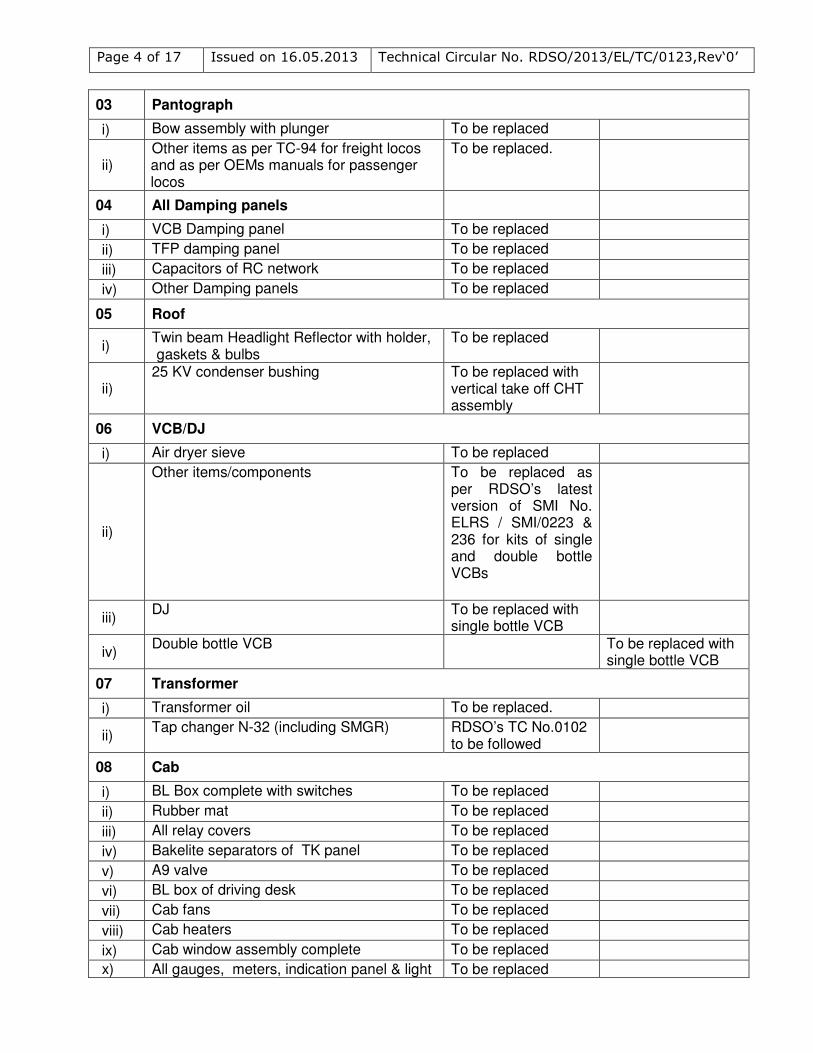
03 Pantograph
i) Bow assembly with plunger To be replaced
ii) Other items as per TC-94 for freight locos and as per OEMs manuals for passenger locos
To be replaced.
04 All Damping panels
i) VCB Damping panel To be replaced
ii) TFP damping panel To be replaced
iii) Capacitors of RC network To be replaced
iv) Other Damping panels To be replaced
05 Roof
i) Twin beam Headlight Reflector with holder, gaskets & bulbs
To be replaced
ii) 25 KV condenser bushing To be replaced with
vertical take off CHT assembly
06 VCB/DJ
i) Air dryer sieve To be replaced
ii)
Other items/components To be replaced as per RDSO’s latest version of SMI No. ELRS / SMI/0223 & 236 for kits of single and double bottle VCBs
iii) DJ To be replaced with
single bottle VCB
iv) Double bottle VCB To be replaced with
single bottle VCB
07 Transformer
i) Transformer oil To be replaced.
ii) Tap changer N-32 (including SMGR) RDSO’s TC No.0102
to be followed
08 Cab
i) BL Box complete with switches To be replaced
ii) Rubber mat To be replaced
iii) All relay covers To be replaced
iv) Bakelite separators of TK panel To be replaced
v) A9 valve To be replaced
vi) BL box of driving desk To be replaced
vii) Cab fans To be replaced
viii) Cab heaters To be replaced
ix) Cab window assembly complete To be replaced
x) All gauges, meters, indication panel & light To be replaced
Page 5 of 17 Issued on 16.05.2013 Technical Circular No. RDSO/2013/EL/TC/0123,Rev‘0’
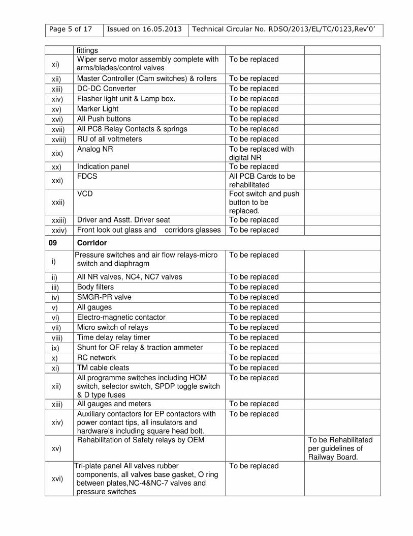
fittings
xi) Wiper servo motor assembly complete with arms/blades/control valves
To be replaced
xii) Master Controller (Cam switches) & rollers To be replaced
xiii) DC-DC Converter To be replaced
xiv) Flasher light unit & Lamp box. To be replaced
xv) Marker Light To be replaced
xvi) All Push buttons To be replaced
xvii) All PC8 Relay Contacts & springs To be replaced
xviii) RU of all voltmeters To be replaced
xix) Analog NR To be replaced with
digital NR
xx) Indication panel To be replaced
xxi) FDCS All PCB Cards to be
rehabilitated
xxii) VCD Foot switch and push
button to be replaced.
xxiii) Driver and Asstt. Driver seat To be replaced
xxiv) Front look out glass and corridors glasses To be replaced
09 Corridor
i) Pressure switches and air flow relays-micro switch and diaphragm
To be replaced
ii) All NR valves, NC4, NC7 valves To be replaced
iii) Body filters To be replaced
iv) SMGR-PR valve To be replaced
v) All gauges To be replaced
vi) Electro-magnetic contactor To be replaced
vii) Micro switch of relays To be replaced
viii) Time delay relay timer To be replaced
ix) Shunt for QF relay & traction ammeter To be replaced
x) RC network To be replaced
xi) TM cable cleats To be replaced
xii) All programme switches including HOM switch, selector switch, SPDP toggle switch & D type fuses
To be replaced
xiii) All gauges and meters To be replaced
xiv) Auxiliary contactors for EP contactors with power contact tips, all insulators and hardware’s including square head bolt.
To be replaced
xv) Rehabilitation of Safety relays by OEM To be Rehabilitated
per guidelines of Railway Board.
xvi)
Tri-plate panel All valves rubber components, all valves base gasket, O ring between plates,NC-4&NC-7 valves and pressure switches
To be replaced
Page 6 of 17 Issued on 16.05.2013 Technical Circular No. RDSO/2013/EL/TC/0123,Rev‘0’
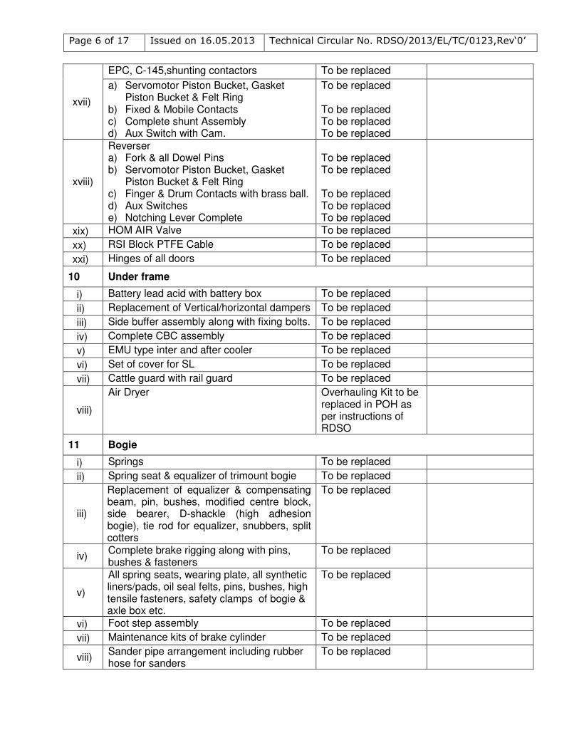
xvii)
EPC, C-145,shunting contactors To be replaced
a) Servomotor Piston Bucket, Gasket Piston Bucket & Felt Ring
b) Fixed & Mobile Contacts c) Complete shunt Assembly d) Aux Switch with Cam.
To be replaced To be replaced To be replaced To be replaced
xviii)
Reverser a) Fork & all Dowel Pins b) Servomotor Piston Bucket, Gasket
Piston Bucket & Felt Ring c) Finger & Drum Contacts with brass ball. d) Aux Switches e) Notching Lever Complete
To be replaced To be replaced To be replaced To be replaced To be replaced
xix) HOM AIR Valve To be replaced
xx) RSI Block PTFE Cable To be replaced
xxi) Hinges of all doors To be replaced
10 Under frame
i) Battery lead acid with battery box To be replaced
ii) Replacement of Vertical/horizontal dampers To be replaced
iii) Side buffer assembly along with fixing bolts. To be replaced
iv) Complete CBC assembly To be replaced
v) EMU type inter and after cooler To be replaced
vi) Set of cover for SL To be replaced
vii) Cattle guard with rail guard To be replaced
viii)
Air Dryer
Overhauling Kit to be replaced in POH as per instructions of RDSO
11 Bogie
i) Springs To be replaced
ii) Spring seat & equalizer of trimount bogie To be replaced
iii)
Replacement of equalizer & compensating beam, pin, bushes, modified centre block, side bearer, D-shackle (high adhesion bogie), tie rod for equalizer, snubbers, split cotters
To be replaced
iv) Complete brake rigging along with pins, bushes & fasteners
To be replaced
v)
All spring seats, wearing plate, all synthetic liners/pads, oil seal felts, pins, bushes, high tensile fasteners, safety clamps of bogie & axle box etc.
To be replaced
vi) Foot step assembly To be replaced
vii) Maintenance kits of brake cylinder To be replaced
viii) Sander pipe arrangement including rubber hose for sanders
To be replaced
Page 7 of 17 Issued on 16.05.2013 Technical Circular No. RDSO/2013/EL/TC/0123,Rev‘0’
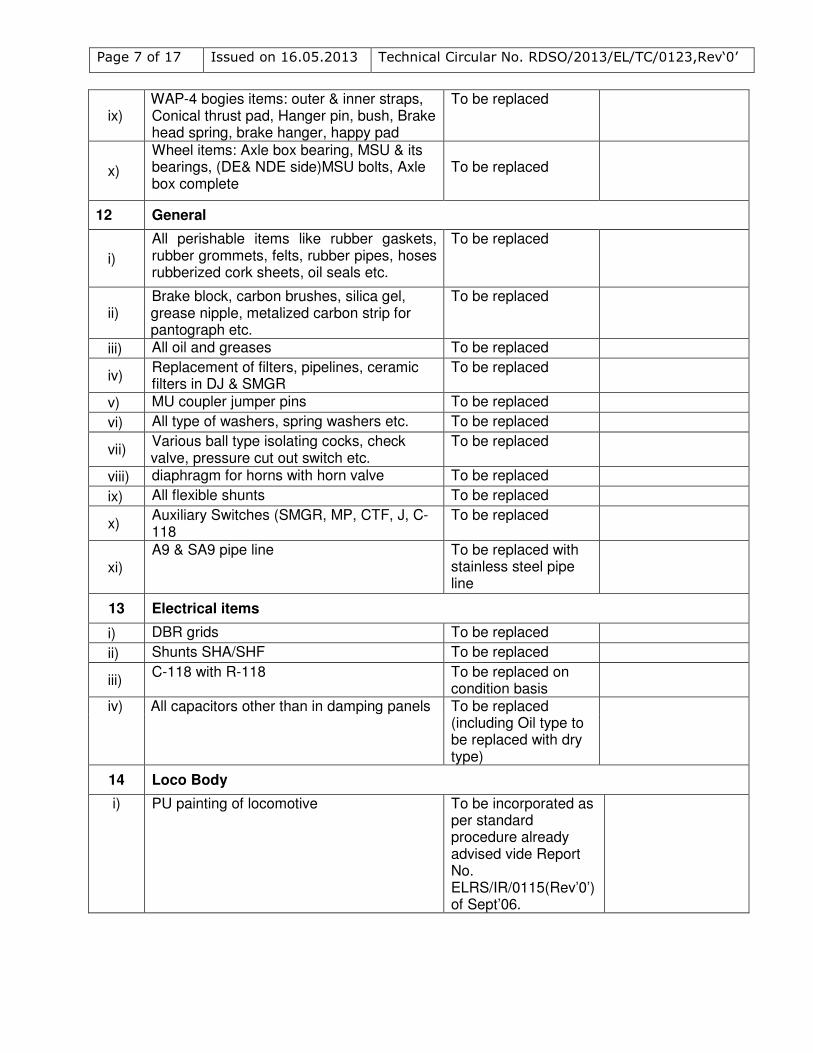
ix) WAP-4 bogies items: outer & inner straps, Conical thrust pad, Hanger pin, bush, Brake head spring, brake hanger, happy pad
To be replaced
x)
Wheel items: Axle box bearing, MSU & its bearings, (DE& NDE side)MSU bolts, Axle box complete
To be replaced
12 General
i)
All perishable items like rubber gaskets, rubber grommets, felts, rubber pipes, hoses rubberized cork sheets, oil seals etc.
To be replaced
ii) Brake block, carbon brushes, silica gel, grease nipple, metalized carbon strip for pantograph etc.
To be replaced
iii) All oil and greases To be replaced
iv) Replacement of filters, pipelines, ceramic filters in DJ & SMGR
To be replaced
v) MU coupler jumper pins To be replaced
vi) All type of washers, spring washers etc. To be replaced
vii) Various ball type isolating cocks, check valve, pressure cut out switch etc.
To be replaced
viii) diaphragm for horns with horn valve To be replaced
ix) All flexible shunts To be replaced
x) Auxiliary Switches (SMGR, MP, CTF, J, C-118
To be replaced
xi)
A9 & SA9 pipe line To be replaced with stainless steel pipe line
13 Electrical items
i) DBR grids To be replaced
ii) Shunts SHA/SHF To be replaced
iii) C-118 with R-118 To be replaced on
condition basis
iv) All capacitors other than in damping panels To be replaced (including Oil type to be replaced with dry type)
14 Loco Body
i) PU painting of locomotive To be incorporated as per standard procedure already advised vide Report No. ELRS/IR/0115(Rev’0’) of Sept’06.
Page 8 of 17 Issued on 16.05.2013 Technical Circular No. RDSO/2013/EL/TC/0123,Rev‘0’
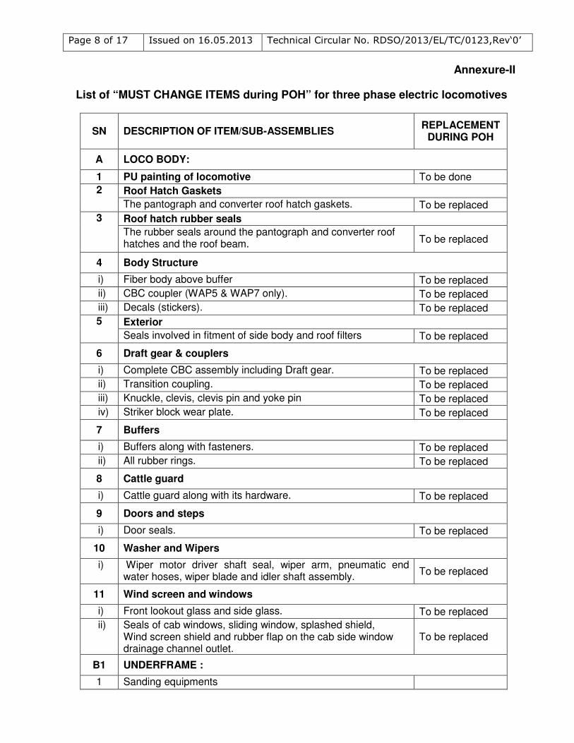
Annexure-II
List of “MUST CHANGE ITEMS during POH” for three phase electric locomotives
SN DESCRIPTION OF ITEM/SUB-ASSEMBLIES REPLACEMENT
DURING POH
A LOCO BODY:
1 PU painting of locomotive To be done
2 Roof Hatch Gaskets
The pantograph and converter roof hatch gaskets. To be replaced
3 Roof hatch rubber seals
The rubber seals around the pantograph and converter roof hatches and the roof beam. To be replaced
4 Body Structure
i) Fiber body above buffer To be replaced
ii) CBC coupler (WAP5 & WAP7 only). To be replaced
iii) Decals (stickers). To be replaced
5 Exterior
Seals involved in fitment of side body and roof filters To be replaced
6 Draft gear & couplers
i) Complete CBC assembly including Draft gear. To be replaced
ii) Transition coupling. To be replaced
iii) Knuckle, clevis, clevis pin and yoke pin To be replaced
iv) Striker block wear plate. To be replaced
7 Buffers
i) Buffers along with fasteners. To be replaced
ii) All rubber rings. To be replaced
8 Cattle guard
i) Cattle guard along with its hardware. To be replaced
9 Doors and steps
i) Door seals. To be replaced
10 Washer and Wipers
i) Wiper motor driver shaft seal, wiper arm, pneumatic end water hoses, wiper blade and idler shaft assembly.
To be replaced
11 Wind screen and windows
i) Front lookout glass and side glass. To be replaced
ii) Seals of cab windows, sliding window, splashed shield, Wind screen shield and rubber flap on the cab side window drainage channel outlet.
To be replaced
B1 UNDERFRAME :
1 Sanding equipments
Page 9 of 17 Issued on 16.05.2013 Technical Circular No. RDSO/2013/EL/TC/0123,Rev‘0’
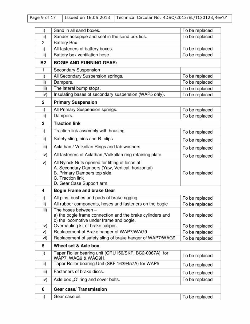
i) Sand in all sand boxes. To be replaced
ii) Sander hosepipe and seal in the sand box lids. To be replaced
2 Battery Box
i) All fasteners of battery boxes. To be replaced
ii) Battery box ventilation hose. To be replaced
B2 BOGIE AND RUNNING GEAR:
1 Secondary Suspension
i) All Secondary Suspension springs. To be replaced
ii) Dampers. To be replaced
iii) The lateral bump stops. To be replaced
iv) Insulating bases of secondary suspension (WAP5 only). To be replaced
2 Primary Suspension
i) All Primary Suspension springs. To be replaced
ii) Dampers. To be replaced
3 Traction link
i) Traction link assembly with housing. To be replaced
ii) Safety sling, pins and R- clips. To be replaced
iii) Aclathan / Vulkollan Rings and tab washers. To be replaced
iv) All fasteners of Aclathan /Vulkollan ring retaining plate. To be replaced
v) All Nylock Nuts opened for lifting of locos at: A. Secondary Dampers (Yaw, Vertical, horizontal) B. Primary Dampers top side. C. Traction link D. Gear Case Support arm.
To be replaced
4 Bogie Frame and brake Gear
i) All pins, bushes and pads of brake rigging To be replaced
ii) All rubber components, hoses and fasteners on the bogie To be replaced
iii) The hoses between – a) the bogie frame connection and the brake cylinders and b) the locomotive under frame and bogie.
To be replaced
iv) Overhauling kit of brake caliper. To be replaced
v) Replacement of Brake hanger of WAP7/WAG9 To be replaced
vi) Replacement of safety sling of brake hanger of WAP7/WAG9 To be replaced
5 Wheel set & Axle box
i) Taper Roller bearing unit (CRU150/SKF, BC2-0067A) for WAP7, WAG9 & WAG9H.
To be replaced
ii) Taper Roller bearing Unit (SKF 1639457A) for WAP5 To be replaced
iii) Fasteners of brake discs. To be replaced
iv) Axle box „O’ ring and cover bolts. To be replaced
6 Gear case/ Transmission
i) Gear case oil. To be replaced
Page 10 of 17 Issued on 16.05.2013 Technical Circular No. RDSO/2013/EL/TC/0123,Rev‘0’
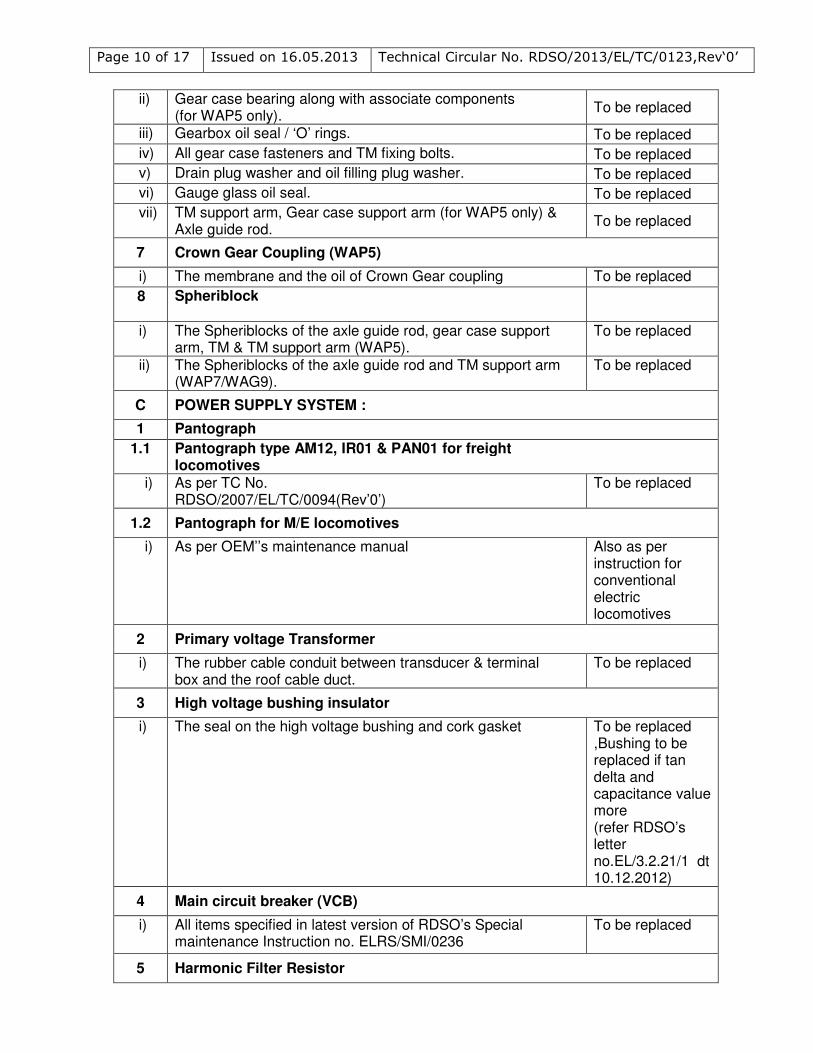
ii) Gear case bearing along with associate components (for WAP5 only).
To be replaced
iii) Gearbox oil seal / ‘O’ rings. To be replaced
iv) All gear case fasteners and TM fixing bolts. To be replaced
v) Drain plug washer and oil filling plug washer. To be replaced
vi) Gauge glass oil seal. To be replaced
vii) TM support arm, Gear case support arm (for WAP5 only) & Axle guide rod.
To be replaced
7 Crown Gear Coupling (WAP5)
i) The membrane and the oil of Crown Gear coupling To be replaced
8 Spheriblock
i) The Spheriblocks of the axle guide rod, gear case support arm, TM & TM support arm (WAP5).
To be replaced
ii)
The Spheriblocks of the axle guide rod and TM support arm (WAP7/WAG9).
To be replaced
C POWER SUPPLY SYSTEM :
1 Pantograph
1.1
Pantograph type AM12, IR01 & PAN01 for freight locomotives
i) As per TC No. RDSO/2007/EL/TC/0094(Rev’0’)
To be replaced
1.2 Pantograph for M/E locomotives
i) As per OEM’’s maintenance manual Also as per instruction for conventional electric locomotives
2 Primary voltage Transformer
i)
The rubber cable conduit between transducer & terminal box and the roof cable duct.
To be replaced
3 High voltage bushing insulator
i) The seal on the high voltage bushing and cork gasket To be replaced ,Bushing to be replaced if tan delta and capacitance value more (refer RDSO’s letter no.EL/3.2.21/1 dt 10.12.2012)
4 Main circuit breaker (VCB)
i) All items specified in latest version of RDSO’s Special maintenance Instruction no. ELRS/SMI/0236
To be replaced
5 Harmonic Filter Resistor
Page 11 of 17 Issued on 16.05.2013 Technical Circular No. RDSO/2013/EL/TC/0123,Rev‘0’
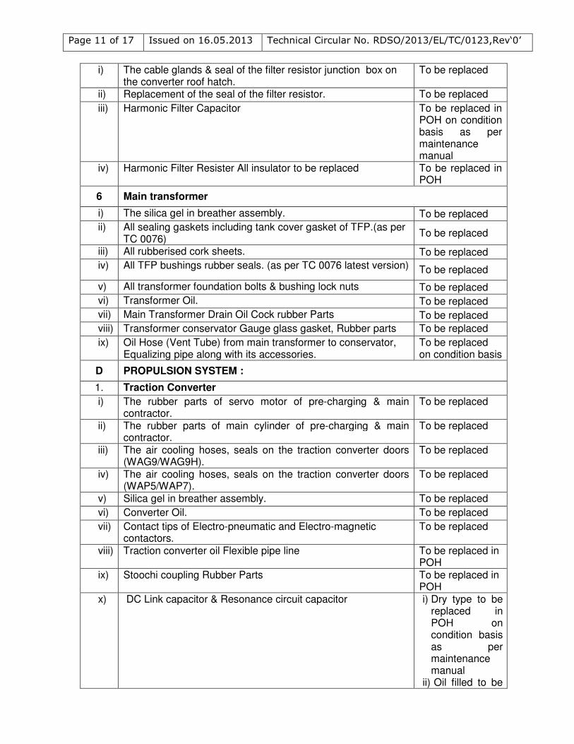
i) The cable glands & seal of the filter resistor junction box on the converter roof hatch.
To be replaced
ii) Replacement of the seal of the filter resistor. To be replaced
iii) Harmonic Filter Capacitor To be replaced in POH on condition basis as per maintenance manual
iv) Harmonic Filter Resister All insulator to be replaced To be replaced in POH
6 Main transformer
i) The silica gel in breather assembly. To be replaced
ii) All sealing gaskets including tank cover gasket of TFP.(as per TC 0076)
To be replaced
iii) All rubberised cork sheets. To be replaced
iv) All TFP bushings rubber seals. (as per TC 0076 latest version) To be replaced
v) All transformer foundation bolts & bushing lock nuts To be replaced
vi) Transformer Oil. To be replaced
vii) Main Transformer Drain Oil Cock rubber Parts To be replaced
viii) Transformer conservator Gauge glass gasket, Rubber parts To be replaced
ix) Oil Hose (Vent Tube) from main transformer to conservator, Equalizing pipe along with its accessories.
To be replaced on condition basis
D PROPULSION SYSTEM :
1. Traction Converter
i) The rubber parts of servo motor of pre-charging & main contractor.
To be replaced
ii) The rubber parts of main cylinder of pre-charging & main contractor.
To be replaced
iii) The air cooling hoses, seals on the traction converter doors (WAG9/WAG9H).
To be replaced
iv) The air cooling hoses, seals on the traction converter doors (WAP5/WAP7).
To be replaced
v) Silica gel in breather assembly. To be replaced
vi) Converter Oil. To be replaced
vii)
Contact tips of Electro-pneumatic and Electro-magnetic contactors.
To be replaced
viii) Traction converter oil Flexible pipe line To be replaced in POH
ix) Stoochi coupling Rubber Parts To be replaced in POH
x) DC Link capacitor & Resonance circuit capacitor i) Dry type to be replaced in POH on condition basis as per maintenance manual
ii) Oil filled to be
Page 12 of 17 Issued on 16.05.2013 Technical Circular No. RDSO/2013/EL/TC/0123,Rev‘0’
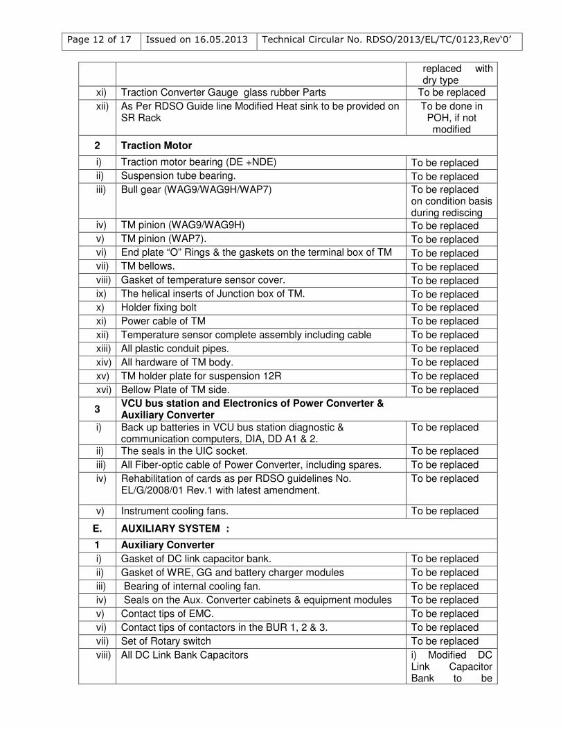
replaced with dry type
xi) Traction Converter Gauge glass rubber Parts To be replaced
xii)
As Per RDSO Guide line Modified Heat sink to be provided on SR Rack
To be done in POH, if not modified
2 Traction Motor
i) Traction motor bearing (DE +NDE) To be replaced
ii) Suspension tube bearing. To be replaced
iii) Bull gear (WAG9/WAG9H/WAP7) To be replaced on condition basis during rediscing
iv) TM pinion (WAG9/WAG9H) To be replaced
v) TM pinion (WAP7). To be replaced
vi) End plate “O” Rings & the gaskets on the terminal box of TM To be replaced
vii) TM bellows. To be replaced
viii) Gasket of temperature sensor cover. To be replaced
ix) The helical inserts of Junction box of TM. To be replaced
x) Holder fixing bolt To be replaced
xi) Power cable of TM To be replaced
xii) Temperature sensor complete assembly including cable To be replaced
xiii) All plastic conduit pipes. To be replaced
xiv) All hardware of TM body. To be replaced
xv) TM holder plate for suspension 12R To be replaced
xvi) Bellow Plate of TM side. To be replaced
3 VCU bus station and Electronics of Power Converter & Auxiliary Converter
i) Back up batteries in VCU bus station diagnostic & communication computers, DIA, DD A1 & 2.
To be replaced
ii) The seals in the UIC socket. To be replaced
iii) All Fiber-optic cable of Power Converter, including spares. To be replaced
iv)
Rehabilitation of cards as per RDSO guidelines No. EL/G/2008/01 Rev.1 with latest amendment.
To be replaced
v) Instrument cooling fans. To be replaced
E. AUXILIARY SYSTEM :
1 Auxiliary Converter
i) Gasket of DC link capacitor bank. To be replaced
ii) Gasket of WRE, GG and battery charger modules To be replaced
iii) Bearing of internal cooling fan. To be replaced
iv) Seals on the Aux. Converter cabinets & equipment modules To be replaced
v) Contact tips of EMC. To be replaced
vi) Contact tips of contactors in the BUR 1, 2 & 3. To be replaced
vii) Set of Rotary switch To be replaced
viii) All DC Link Bank Capacitors i) Modified DC Link Capacitor Bank to be
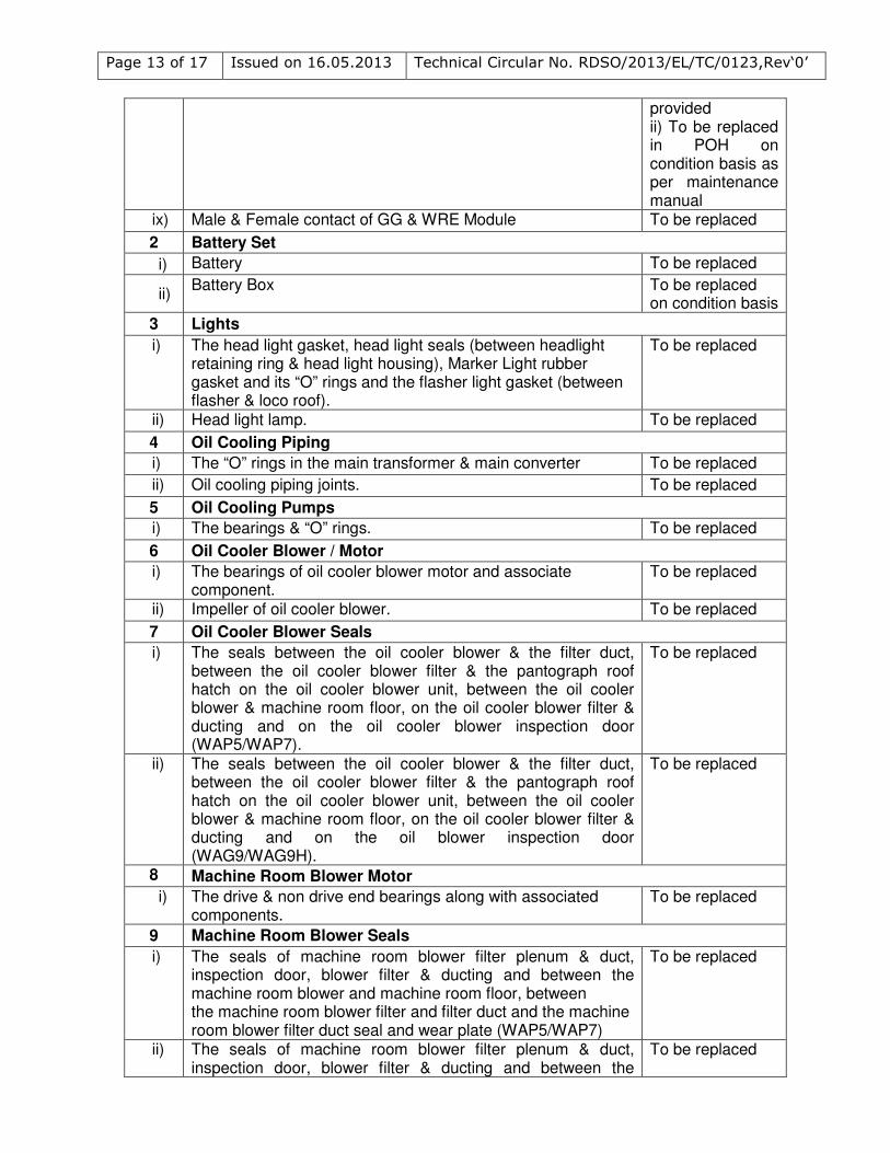
Page 13 of 17 Issued on 16.05.2013 Technical Circular No. RDSO/2013/EL/TC/0123,Rev‘0’
provided ii) To be replaced in POH on condition basis as per maintenance manual
ix) Male & Female contact of GG & WRE Module To be replaced
2 Battery Set
i) Battery To be replaced
ii) Battery Box To be replaced
on condition basis
3 Lights
i) The head light gasket, head light seals (between headlight retaining ring & head light housing), Marker Light rubber gasket and its “O” rings and the flasher light gasket (between flasher & loco roof).
To be replaced
ii) Head light lamp. To be replaced
4 Oil Cooling Piping
i) The “O” rings in the main transformer & main converter To be replaced
ii) Oil cooling piping joints. To be replaced
5 Oil Cooling Pumps
i) The bearings & “O” rings. To be replaced
6 Oil Cooler Blower / Motor
i) The bearings of oil cooler blower motor and associate component.
To be replaced
ii) Impeller of oil cooler blower. To be replaced
7 Oil Cooler Blower Seals
i) The seals between the oil cooler blower & the filter duct, between the oil cooler blower filter & the pantograph roof hatch on the oil cooler blower unit, between the oil cooler blower & machine room floor, on the oil cooler blower filter & ducting and on the oil cooler blower inspection door (WAP5/WAP7).
To be replaced
ii) The seals between the oil cooler blower & the filter duct, between the oil cooler blower filter & the pantograph roof hatch on the oil cooler blower unit, between the oil cooler blower & machine room floor, on the oil cooler blower filter & ducting and on the oil blower inspection door (WAG9/WAG9H).
To be replaced
8 Machine Room Blower Motor
i)
The drive & non drive end bearings along with associated components.
To be replaced
9 Machine Room Blower Seals
i) The seals of machine room blower filter plenum & duct, inspection door, blower filter & ducting and between the machine room blower and machine room floor, between the machine room blower filter and filter duct and the machine room blower filter duct seal and wear plate (WAP5/WAP7)
To be replaced
ii) The seals of machine room blower filter plenum & duct, inspection door, blower filter & ducting and between the
To be replaced
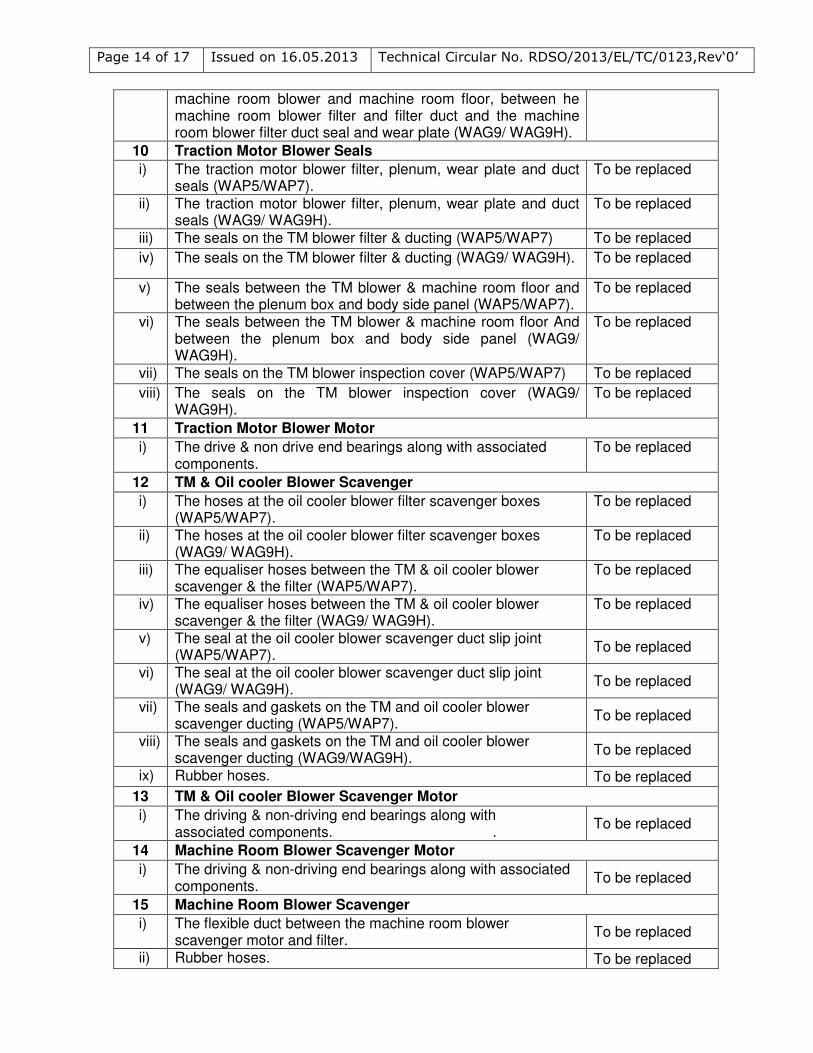
Page 14 of 17 Issued on 16.05.2013 Technical Circular No. RDSO/2013/EL/TC/0123,Rev‘0’
machine room blower and machine room floor, between he machine room blower filter and filter duct and the machine room blower filter duct seal and wear plate (WAG9/ WAG9H).
10 Traction Motor Blower Seals
i) The traction motor blower filter, plenum, wear plate and duct seals (WAP5/WAP7).
To be replaced
ii) The traction motor blower filter, plenum, wear plate and duct seals (WAG9/ WAG9H).
To be replaced
iii) The seals on the TM blower filter & ducting (WAP5/WAP7) To be replaced
iv) The seals on the TM blower filter & ducting (WAG9/ WAG9H). To be replaced
v) The seals between the TM blower & machine room floor and between the plenum box and body side panel (WAP5/WAP7).
To be replaced
vi) The seals between the TM blower & machine room floor And between the plenum box and body side panel (WAG9/ WAG9H).
To be replaced
vii) The seals on the TM blower inspection cover (WAP5/WAP7) To be replaced
viii) The seals on the TM blower inspection cover (WAG9/ WAG9H).
To be replaced
11 Traction Motor Blower Motor
i) The drive & non drive end bearings along with associated components.
To be replaced
12 TM & Oil cooler Blower Scavenger
i) The hoses at the oil cooler blower filter scavenger boxes (WAP5/WAP7).
To be replaced
ii) The hoses at the oil cooler blower filter scavenger boxes (WAG9/ WAG9H).
To be replaced
iii) The equaliser hoses between the TM & oil cooler blower scavenger & the filter (WAP5/WAP7).
To be replaced
iv) The equaliser hoses between the TM & oil cooler blower scavenger & the filter (WAG9/ WAG9H).
To be replaced
v) The seal at the oil cooler blower scavenger duct slip joint (WAP5/WAP7).
To be replaced
vi) The seal at the oil cooler blower scavenger duct slip joint (WAG9/ WAG9H).
To be replaced
vii) The seals and gaskets on the TM and oil cooler blower scavenger ducting (WAP5/WAP7).
To be replaced
viii) The seals and gaskets on the TM and oil cooler blower scavenger ducting (WAG9/WAG9H).
To be replaced
ix) Rubber hoses. To be replaced
13 TM & Oil cooler Blower Scavenger Motor
i) The driving & non-driving end bearings along with associated components. .
To be replaced
14 Machine Room Blower Scavenger Motor
i) The driving & non-driving end bearings along with associated components.
To be replaced
15 Machine Room Blower Scavenger
i) The flexible duct between the machine room blower scavenger motor and filter.
To be replaced
ii) Rubber hoses. To be replaced
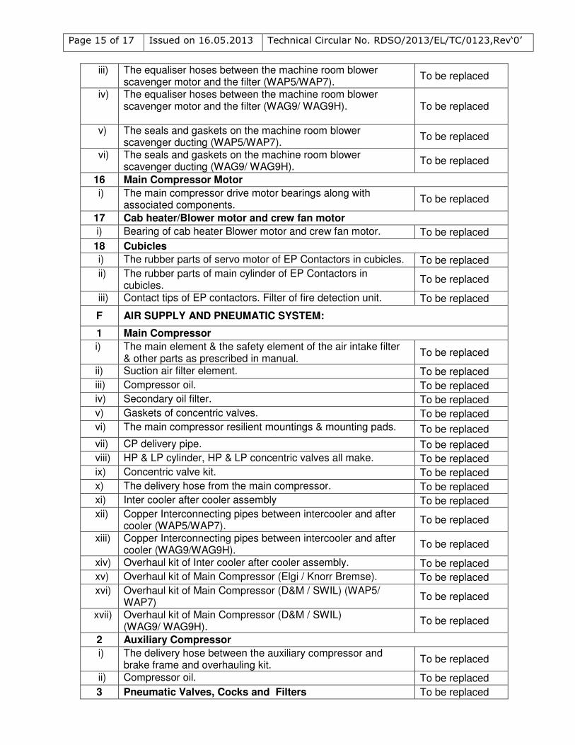
Page 15 of 17 Issued on 16.05.2013 Technical Circular No. RDSO/2013/EL/TC/0123,Rev‘0’
iii) The equaliser hoses between the machine room blower scavenger motor and the filter (WAP5/WAP7).
To be replaced
iv) The equaliser hoses between the machine room blower scavenger motor and the filter (WAG9/ WAG9H).
To be replaced
v) The seals and gaskets on the machine room blower scavenger ducting (WAP5/WAP7).
To be replaced
vi) The seals and gaskets on the machine room blower scavenger ducting (WAG9/ WAG9H).
To be replaced
16 Main Compressor Motor
i) The main compressor drive motor bearings along with associated components.
To be replaced
17 Cab heater/Blower motor and crew fan motor
i) Bearing of cab heater Blower motor and crew fan motor. To be replaced
18 Cubicles
i) The rubber parts of servo motor of EP Contactors in cubicles. To be replaced
ii) The rubber parts of main cylinder of EP Contactors in cubicles.
To be replaced
iii) Contact tips of EP contactors. Filter of fire detection unit. To be replaced
F AIR SUPPLY AND PNEUMATIC SYSTEM:
1 Main Compressor
i) The main element & the safety element of the air intake filter & other parts as prescribed in manual.
To be replaced
ii) Suction air filter element. To be replaced
iii) Compressor oil. To be replaced
iv) Secondary oil filter. To be replaced
v) Gaskets of concentric valves. To be replaced
vi) The main compressor resilient mountings & mounting pads. To be replaced
vii) CP delivery pipe. To be replaced
viii) HP & LP cylinder, HP & LP concentric valves all make. To be replaced
ix) Concentric valve kit. To be replaced
x) The delivery hose from the main compressor. To be replaced
xi) Inter cooler after cooler assembly To be replaced
xii) Copper Interconnecting pipes between intercooler and after cooler (WAP5/WAP7).
To be replaced
xiii) Copper Interconnecting pipes between intercooler and after cooler (WAG9/WAG9H).
To be replaced
xiv) Overhaul kit of Inter cooler after cooler assembly. To be replaced
xv) Overhaul kit of Main Compressor (Elgi / Knorr Bremse). To be replaced
xvi) Overhaul kit of Main Compressor (D&M / SWIL) (WAP5/ WAP7)
To be replaced
xvii) Overhaul kit of Main Compressor (D&M / SWIL) (WAG9/ WAG9H).
To be replaced
2 Auxiliary Compressor
i) The delivery hose between the auxiliary compressor and brake frame and overhauling kit.
To be replaced
ii) Compressor oil. To be replaced
3 Pneumatic Valves, Cocks and Filters To be replaced
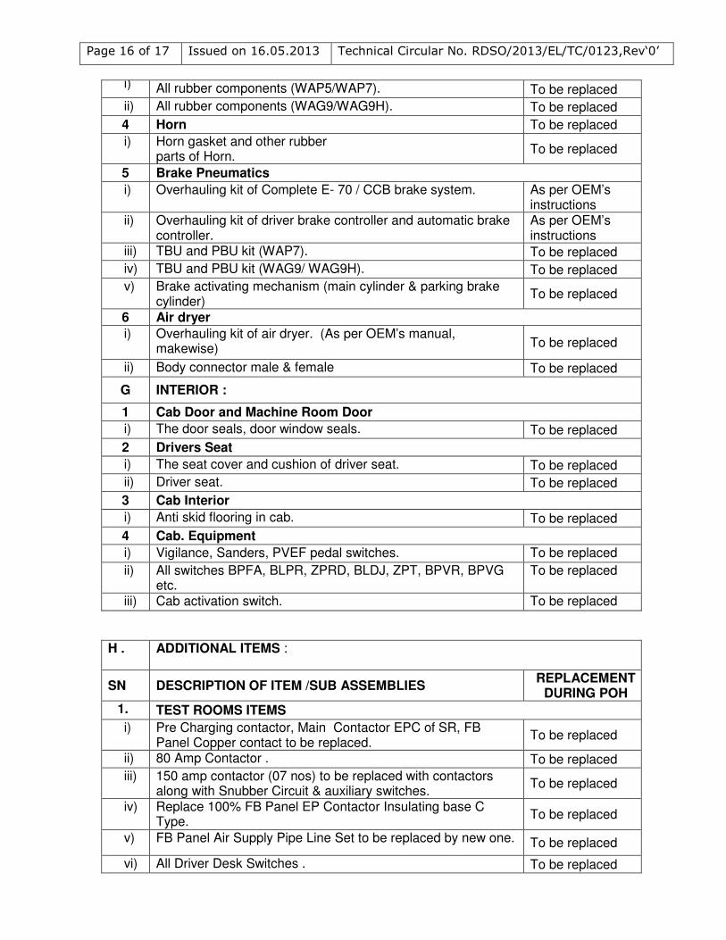
Page 16 of 17 Issued on 16.05.2013 Technical Circular No. RDSO/2013/EL/TC/0123,Rev‘0’
i) All rubber components (WAP5/WAP7). To be replaced
ii) All rubber components (WAG9/WAG9H). To be replaced
4 Horn To be replaced
i) Horn gasket and other rubber parts of Horn.
To be replaced
5 Brake Pneumatics
i) Overhauling kit of Complete E- 70 / CCB brake system. As per OEM’s instructions
ii) Overhauling kit of driver brake controller and automatic brake controller.
As per OEM’s instructions
iii) TBU and PBU kit (WAP7). To be replaced
iv) TBU and PBU kit (WAG9/ WAG9H). To be replaced
v) Brake activating mechanism (main cylinder & parking brake cylinder)
To be replaced
6 Air dryer
i) Overhauling kit of air dryer. (As per OEM’s manual, makewise) To be replaced
ii) Body connector male & female To be replaced
G INTERIOR :
1 Cab Door and Machine Room Door
i) The door seals, door window seals. To be replaced
2 Drivers Seat
i) The seat cover and cushion of driver seat. To be replaced
ii) Driver seat. To be replaced
3 Cab Interior
i) Anti skid flooring in cab. To be replaced
4 Cab. Equipment
i) Vigilance, Sanders, PVEF pedal switches. To be replaced
ii) All switches BPFA, BLPR, ZPRD, BLDJ, ZPT, BPVR, BPVG etc.
To be replaced
iii) Cab activation switch. To be replaced
H . ADDITIONAL ITEMS :
SN DESCRIPTION OF ITEM /SUB ASSEMBLIES REPLACEMENT
DURING POH 1. TEST ROOMS ITEMS
i) Pre Charging contactor, Main Contactor EPC of SR, FB Panel Copper contact to be replaced.
To be replaced
ii) 80 Amp Contactor . To be replaced
iii) 150 amp contactor (07 nos) to be replaced with contactors along with Snubber Circuit & auxiliary switches.
To be replaced
iv) Replace 100% FB Panel EP Contactor Insulating base C Type.
To be replaced
v) FB Panel Air Supply Pipe Line Set to be replaced by new one. To be replaced
vi) All Driver Desk Switches . To be replaced
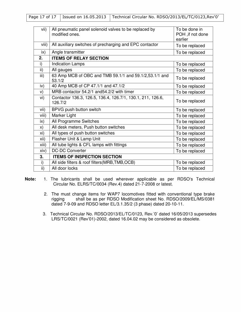
Page 17 of 17 Issued on 16.05.2013 Technical Circular No. RDSO/2013/EL/TC/0123,Rev‘0’
vii) All pneumatic panel solenoid valves to be replaced by modified ones.
To be done in POH ,if not done earlier
viii) All auxiliary switches of precharging and EPC contactor To be replaced
ix) Angle transmitter To be replaced
2. ITEMS OF RELAY SECTION
i) Indication Lamps To be replaced
ii) All gauges To be replaced
iii) 63 Amp MCB of OBC and TMB 59.1/1 and 59.1/2,53.1/1 and 53.1/2
To be replaced
iv) 40 Amp MCB of CP 47.1/1 and 47.1/2 To be replaced
v) MRB contactor 54.2/1 and54.2/2 with timer To be replaced
vi) Contactor 136.3, 126.5, 136.4, 126.7/1, 130.1, 211, 126.6, 126.7/2 To be replaced
vii) BPVG push button switch To be replaced
viii) Marker Light To be replaced
ix) All Programme Switches To be replaced
x) All desk meters, Push button switches To be replaced
xi) All types of push button switches To be replaced
xii) Flasher Unit & Lamp Unit To be replaced
xiii) All tube lights & CFL lamps with fittings To be replaced
xiv) DC-DC Converter To be replaced
3. ITEMS OF INSPECTION SECTION
i) All side filters & roof filters(MRB,TMB,OCB) To be replaced
ii) All door locks To be replaced
Note: 1. The lubricants shall be used wherever applicable as per RDSO‘s Technical
Circular No. ELRS/TC/0034 (Rev.4) dated 21-7-2008 or latest. 2. The must change items for WAP7 locomotives fitted with conventional type brake
rigging shall be as per RDSO Modification sheet No. RDSO/2009/EL/MS/0381 dated 7-9-09 and RDSO letter EL/3.1.35/2 (3 phase) dated 20-10-11.
3. Technical Circular No. RDSO/2013/EL/TC/0123, Rev.’0’ dated 16/05/2013 supersedes
LRS/TC/0021 (Rev’01)-2002, dated 16.04.02 may be considered as obsolete.


![Denumire contract Autoritate contractanta Data publicare ... · [136410] SUPORT TEHNIC PENTRU SISTEMUL SIVECO APPLICATIONS 2011 AGENTIA NATIONALA DE IMBUNATATIRI FUNCIARE 16.05.2013](https://img.pdfslide.us/doc/110x75/5e07b853920d3c00406805b9/denumire-contract-autoritate-contractanta-data-publicare-136410-suport-tehnic.jpg)