Embed Size (px)
Citation preview

Page 1 of 40

Page 2 of 40
Document catalogue no. 0100-09 Document revision – 015 Last updated – April 2011 Updated by – Andrew Brown
Contents
SECTION / Page No. Description
SECTION 1 SARFINDER® GPS plot locator system
4 Overview & Declaration of Conformity
5 Parts List
6 System components
7 – 8 Display functions
9 Mounting the display
10 Mounting and fitting the antenna correctly
11 Electrical connections
12 Antenna cable connections
13 CREWFIX® NMEA
14 – 15 How to use the SARfinder – testing the system/undertaking a sea trial
16 – 17 Problem solving
SECTION 2 Crewguard GPS plot MOB alerting system
18 Overview & Declaration of Conformity
19 Parts list
19 – 20 System components
20 Technical characteristics
21 Testing the system
22 Wiring
22 Mounting the control box
23 CREWFIX® NMEA
SECTION 3 Crewguard MOB monitor alarm
24 Overview & DOC
25 Parts list
25 Technical data
26 Testing the system
27 Wiring
27 Mounting the control box
SECTION 4 Lone Worker systems
28 Overview
29 Parts list
30 System components
31 Testing the system
32-33 Examples of Sea Marshall® Lone Worker systems
SECTION 5 CREWFIX® NMEA
34 Overview
SECTION 6 SARfinder® transportable systems
35 - 39
39 Pictorial SARfinder® user guide

Page 3 of 40
Marine Rescue Technologies ltd. are pleased to present this manual covering their range of Sea Marshall® Maritime Survivor
Locating Device receivers. The Sea Marshall® products are recognised as the industry standard for self managed safety alert &
locate safety systems for commercial use. In this booklet you will find a product overview and operator instructions for each of
the following products:
1. SARfinder® GPS plot MOB/Lost Diver self managed alert/locator safety system
2. Crewguard GPS plot MOB alerting safety system
3. Crewguard Man Overboard monitor Alarm
4. Lone worker Crewguard Systems
5. CREWFIX® NMEA GPS output
6. SARfinder® transportable systems
So where do we start? ….What is a Maritime Survivor Locating Device?
A Maritime Survivor Locating Device is made up of 2 components which work together to create a Self-Managed Man Over Board Safety System or Lost Diver Locating Safety System, these 2 components are referred to as Alerting Units (transmitters) and Base Units (receivers).
Fig. 1.0
NOTE – the approximate tracking ranges listed are taken from tests where the receiver antenna has been correctly installed at
the recommended height with the AU9 correctly installed in either an SMB for divers or lifejacket using the self adhesive
universal plb lifejacket fixing kit. The SMB (Dive) gave the maximum range listed as achieved during tests, the lifejacket AU9
installation gave the lower end of the ranges listed (refer to AU9 operator guide for full details). Wearing the AU9 around the
neck will reduce the tracking/alerting ranges to below the ranges listed here in.
Alerting Units are personal transmitters, or personal locator beacons worn by each crewmember on deck or each diver. There is no restriction in the number of Alerting Units that can be used as part of a Sea Marshall® MSLD system. Below is an example of one type of Sea Marshall® Alerting Unit. The following pages describe Base Units (receivers).
Fig. 2.0
Sea Marshall® systems are available to provide safety cover for all of the following applications:
Fig. 3.0
How to use this manual?
All the Sea Marshall receivers are described in detail in this booklet, refer to the table of contents on page 2 for a page reference
for your system. Further information and support can be found on our website www.seamarshall.com

Page 4 of 40
SECTION 1
PRODUCT NAME - SARfinder® GPS plot MOB/Lost diver locating safety system (MK3)
1.0 Overview
Fig. 1.0
The Sea Marshall® SARfinder® GPS plot locating system continuously monitors for an ‘SOS’ signal from a Sea Marshall® Alerting
Unit, the system automatically alerts of a person in distress, automatically plotting the GPS position of the incident and allowing
you to rapidly locate the missing person without calling on the Search and Rescue Services. This system is used by professionals
on a daily basis to provide safety cover. Users included amongst others – River Pilots, Fishermen, Windfarm Operators, Geo-
Survey Companies, Offshore Oil & Gas operators, Dive Tour Operators…
2.0 Declaration Of Conformity
Name of Manufacturer/EU Importer: Address of Manufacturer/EU Importer:
Marine Rescue Technology Limited Units 3 & 4 Front Street Court, Middleton On The Wolds, Driffield, East Yorkshire Y025 9TZ United Kingdom
Declares that product:
SARfinder® GPS Plot Man Overboard Safety System
Conforms to the EMC Directive 2004/108/EC and the R&TTE Directive 1999/5/EC as attested by conformity with the following harmonized standards: ETSI EN 301 489-22 V1.3.1 (2003-11): Electromagnetic compatibility and Radio spectrum Matters (ERM); Electromagnetic Compatibility (EMC) standard for radio equipment and services; Part 22: Specific conditions for ground based VHF aeronautical mobile and fixed radio equipment. ETSI EN 301 489-1 V1.5.1 (2004-11): Electromagnetic compatibility and Radio spectrum Matters (ERM); Electro Magnetic Compatibility (EMC) standard for radio equipment and services; Part 1: Common technical requirements. CREWFIX® EN55022:2006 & EN55024:1998 /A1:2001 /A2:2003 David Marshall Chairman Marine Rescue Technologies Limited 20
th July 2009
Signed : Place : Middleton Date : July 2009

Page 5 of 40
3.0 SARfinder® GPS plot MOB/Lost Diver self managed locating system
DESCRIPTION Quantity
BRIDGE BOX DISPLAY with CREWFIX® GPS plot pre-wired Black metal box with LEDs, Button control panel to the front and two connectors to the rear. The adjustable mounting bracket is pre-fitted. IP-67
1
BRIDGE BOX POWER CABLE Grey 1m power cable with 4 pin connector attached at one end, in line fuse, connects into 4 pin connector on rear of bridge box, IP-67 rated connection.
1
ANTENNA White triangular antenna, (NOTE the antenna is passive it does not need a power supply). IP-67
1
ANTENNA ELEMENTS White antenna tube/elements . Screw fixing onto the antenna fixing points on the body of the antenna, waterproofing washers and sealant supplied.
6
ANTENNA CABLE Approx. 20m black RF cable with 7 pin connector fitted at each end, connects the bridge box to the antenna (IP-67 rated connection), each inner wire is coloured/marked with a number relating to the wiring diagram detailed here in.
1
INSTRUCTION MANUAL Includes Certificate of Conformity for each product
1
PLB Test and training beacons. (normally 1 of live 121.5MHz and 1 of test 121.65MHz)
1
Handwheel bolts and mounting cogs (set of 2 handwheel bolts and 4 mounting cogs) These are pre-fitted to the bridge box
1
Trunnion mount metal bracket Pre-fitted to the bridge box
1
Antenna metal bracket – stainless steel cylinder with flange and three holes in base and three in the side of tube section
1
Round red silicon anti-vibration gasket with 3 holes for mounting under antenna bracket
1
Antenna bracket bolts (with 3 nylon washers) 6
Flush mounting bolts and nuts (for mounting the display into a panel) 4
External Alarm pre-wired to CREWFIX® gps plot 1
CREWFIX® NMEA box 1
Weather resistant cover (MK3 SARfinder® only) for control box display 1
2 M6 nuts & bolts for fastening Base Unit control box display to flat surface 2

Page 6 of 40
4.0 SARfinder GPS plot system components
4.1 MOB Alerting Unit AU9 Test Frequency Training Unit
Fully automatic Man Overboard Alerting unit (PLB). Small & comfortable to wear 121.65MHz/121.775MHz test frequency transmitter provides precision tracking. Flexible cable antenna for ease of fitting into a lifejacket/garment, can be worn around the neck or in a lifejacket, 5 second auto-activation with manual over-ride (unless otherwise stated), 1 meter long antenna cord with hi-bright LED strobe, Internal loudspeaker, 5 year user replaceable battery, LED battery status indicator, 24-36 hour transmission time.
Fig. 3.0 Image shown for representation only
4.2 SARfinder® control box display
Dedicated Man Overboard Alarm/Locator Base Unit. Automatic immediate MOB alerting and tracking. LED MOB warning indicator. Easy to operate and install with user friendly controls. Waterproof IP-X8 display. Approximate range indicator (near or far). High quality construction. Training frequencies 121.65MHz & 121.775MHz. 12V Power (24 to 12V DC converter available on request). External siren included for loud audio MOB alerting. Pre-wired to CREWFIX® NMEA GPS output.
Fig. 4.0
4.3 Antenna
Robust lightweight antenna with mounting brackets. Comes with 20m cable, plugs, fittings.
Fig. 5.0
All the above components combine to create a self managed rescue system
Fig. 2.0

Page 7 of 40
5.0 Display Functions (Display shown fitted in the flush mount position)
Fig. 6.0
1 2
2a
3
4
1
1
5
6
7
8
9

Page 8 of 40
5.1 DISPLAY KEY FUNCTIONS
ENSURE EACH CREWMEMBER READS AND IS FULLY FAMILIAR WITH ALL OF THE FOLLOWING OPERATING FUNCTIONS
1. Bearing LEDs The DF display consists of 24 LED’s giving a bearing resolution of 15°. All bearing LED’s are RED except for the LED at 0° which is ORANGE.
IMPORTANT - IN THE EVENT OF A MAN OVERBOARD MOVING OUT OF RANGE OF THE SARfinder® SYSTEM TAKE A BEARING TO ‘SOS’ TARGET AT THAT
POINT.
2. Frequency Select: 1 button cycles 3 frequencies: 121.500 MHz = (LIVE Frequency, Internationally recognised SAR homing frequency)
121.650 MHz = Test
121.775 MHz = Normally allocated for the Test 2 frequency
2. A A GREEN LED indicator will alert the user to the frequency selection they have made. If after 20 minutes of selecting one of the test frequencies the user
has not returned to 121.5 MHz, the unit will default back to 121.5 MHz automatically.
3. Speaker/ Volume: The user will be able to adjust the speaker volume via two switches; Volume Up and Volume Down. Reducing the volume below the audible limit turns off
the speaker, increasing the volume from this point will turn the speaker back on. On power up the volume will be at its middle setting.
4. RSSI: The received signal strength indicator (RSSI) consists of 4 GREEN LED’s arranged horizontally in the centre of the display and gives an approximate signal
strength indication providing an approximate range indicator, occasionally the unit will not be able to show a clear indication of signal strength.
5. RSI: The received signal indicator (RSI) consists of a single RED LED in the centre of the display (orange/red man symbol insode the SOS logo. THIS LED COMES
ON WHEN A PLB SIGNAL IS RECEIVED. The RSI will FLASH ON & OFF when the target is within very close range as an Anti-Collision Warning indicator.
6. Reset: The reset button, when pressed, restores the unit back to its defaults and clears any bearing drag error. The reset button is pressed immediately after an
alarm is activated to put the system into tracking mode, switching off the alarm and resets the external relay.
7. Tone Detect: When the Tone Detect function is enabled the unit will only react to received signals containing the downward swept tone/modulation of a Sea Marshall®
PLB thereby avoiding false alarms from rogue transmissions. A GREEN LED indicator will show this function is enabled. Also a ‘no volt’ relay output will be
activated for operating external devices. In Tone Detect the unit is passive until an ‘SOS’ signal is detected & recognised; once an ‘SOS’ signal is detected
the internal and external alarm will sound. At this point PRESS THE ‘RESET’ BUTTON and the unit will go into tracking mode, the bearing of the ‘SOS’
signal relative to ships head.
NOTE: THE SARfinder® IS DESIGNED TO BE USED IN NORMAL OPERATION/PLB MONITORING IN TONE DETECT MODE.
8. Power PRESS and HOLD the ON/OFF button to activate the unit. Green LED indicates power ON.
9. Point to Bow This point marks the ships head.
EXTERNAL RELAY CONTROL To cancel/reset an External Alarm, or any other external relay linked instruments press the RESET button 6. For wiring refer to 7.5 fig 15
LED BRIGHTNESS ADJUST Switch the display on, press the ON/OFF button once quickly - press and let go (if you press and hold the SARfinder® will turn off), this puts the unit into
brightness adjust mode: all LEDs will light up so you can see the brightness, use the + - volume adjust buttons to select the required brightness. To exit
brightness adjust quickly press and release the ON/OFF button.
Fig. 7.0
Page 9 of 40
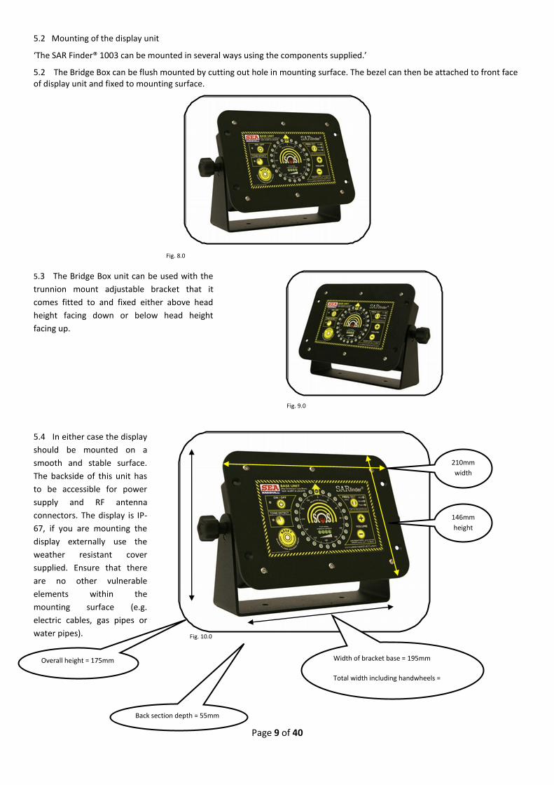
5.2 Mounting of the display unit
‘The SAR Finder® 1003 can be mounted in several ways using the components supplied.’
5.2 The Bridge Box can be flush mounted by cutting out hole in mounting surface. The bezel can then be attached to front face of display unit and fixed to mounting surface.
Fig. 8.0
5.3 The Bridge Box unit can be used with the
trunnion mount adjustable bracket that it
comes fitted to and fixed either above head
height facing down or below head height
facing up.
Fig. 9.0
5.4 In either case the display
should be mounted on a
smooth and stable surface.
The backside of this unit has
to be accessible for power
supply and RF antenna
connectors. The display is IP-
67, if you are mounting the
display externally use the
weather resistant cover
supplied. Ensure that there
are no other vulnerable
elements within the
mounting surface (e.g.
electric cables, gas pipes or
water pipes).
Fig. 10.0
210mm
width
146mm
height
height
Width of bracket base = 195mm
Total width including handwheels =
Overall height = 175mm
Back section depth = 55mm

Page 10 of 40
6.0 Installation of the SARfinder® antenna
Correct antenna positioning
6.1 The position of the antenna array is
of critical importance for the direction
finding efficiency and effective range of
the unit. The mounting position for the
antenna should be as obstacle free as
possible to avoid disturbing reflections
and false readings. The antenna should
be positioned approx 1.5m above any
other metal or antenna.
NOTE: The antenna has an ‘AHEAD →’
to indicate ships head. This point must
be aligned with ships head.
The antenna is to be mounted on a suitable mast tube with an outside diameter of 5cm, using the bracket supplied, round rubber anti-vibration mat and fixing bolts & nylon washers provided.
Fig. 11.0
6.2 Assembly of the antenna
Fig. 12.0
Bracket ID – 50mm Antenna weigth approx 1.7kg
WATERPROOFING THE ANTENNA - IMPORTANT
Repeat application of silicon adhesive for each dipole Check that each dipole is sealed with no gaps

Page 11 of 40
7.0 Electrical Connections
7.1 The connections between the antenna array and display unit are routed via a 20m shielded cable. Connection to the display is internal via an IP-67 rated gland. The power supply and relay are also terminated inside the display enclosure via an IP-67 rated gland. To attach the power cable match up the 4 pin grey coloured power cable to the 4 pin connector on the back of the bridge box. To attach the antenna cable align the 7 pin cable connector to the 7 pin connector on the bridge box, the other end matches to the connector on the underside of the antenna body. A power cable wiring diagram and antenna cable wiring information is enclosed here in subsections 7 through 9.
Fig. 13.0
7.2 AVOID CUTTING THE ANTENNA CONNECTORS FROM THE CABLE, YOU WILL REDUCE THE PERFORMANCE OF YOUR SYSTEM. IF IT IS NECESSARY TO REMOVE A CONNECTOR FIRST TEST THE SYSTEM TO CONFIRM IT IS WORKING, THIS WAY IF THE SYSTEM BEHAVES DIFFERENTLY AFTER THE CONNECTOR HAS BEEN RE-APPLIED YOU WILL KNOW THERE IS A FAULT WITH YOUR WIRING. CUT THE LAST FEW INCHES OFF AND USE THIS AS A REFERENCE FOR RE-ATTACHMENT - REFER TO THE WIRING GUIDE subsections 7 through 9. Only a fully competent/QUALIFIED engineer should attempt this. MRT ltd. cannot be held repsonsible for failure of the unit to work correctly caused by the antenna cable connectors not being re-wired correctly after being removed – each systems is tested at the factory with the plugs affixed and is signed off as fully functional before being despatched. Your warranty does not cover this.
7.3 When installing the system before mounting the antenna first connect the control box to your power supply connect all the cables in accordance with the instructions in this manual and activate the system to check it is working correctly. If you have to remove one of the antenna cable connectors and the system then does not perform as it did in your test you know the fault is located on the cable connection. This unit will run from a 12V power supply only, if your power supply is 24V you will need to install a 24 to 12V DC converter (available from MRT ltd.). If the power supply on your vessel is unreliable, install an isolated power supply. The manufacturer cannot be held responsible for damage caused by wiring the unit into an incorrect power supply, your warranty does not cover this.
7.4 WIRING FOR POWER CABLE / UNIT POWER CONSUMPTION
NOTE: each inner cable has the number marked on.
Pin Cable Description Cable Function
1 Black 1 Relay Contacts
2 Black 2 -V 0V Power
3 Black 3 +V 12V Power
4 Green/Yellow Relay Contacts
POWER CONSUMPTION FOR SARfinder® 1003
ON – 114 mA
ALARM - 500 mA
RESET/SEARCH – 300 mA
Fig. 14.0
7.5 EXTERNAL ALARM
Your unit comes supplied with a small, very loud external siren pre-wired onto the CREWFIX® NMEA box. This siren must be fitted if you are to rely on the SARfinder®1003 to raise the alarm by means of an audio alert. When an ‘SOS’ signal is received the circuit identifies correct characteristics of a Sea Marshall® beacon transmission and activates the external relay to trigger external circuits. The Audio Volume is activated and the display shows the ‘SOS’ signal bearing. Press the RESET button to cancel the External Sounder/Alarm, the Man Overboard Bearing will be displayed. If you want to remove the CREWFIX® for any reason always wire the siren back onto the cable using the wiring diagram below. It is possible to connect the SARfinder to other external alarms.
Fig. 15.0
Page 12 of 40
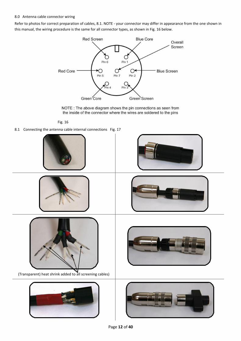
8.0 Antenna cable connector wiring
Refer to photos for correct preparation of cables, 8.1. NOTE - your connector may differ in appearance from the one shown in
this manual, the wiring procedure is the same for all connector types, as shown in Fig. 16 below.
Fig. 16
8.1 Connecting the antenna cable internal connections Fig. 17
(Transparent) heat shrink added to all screening cables)

Page 13 of 40
9.0 GPS plot function
9.1 Overview
The CREWFIX®NMEA output connects to the relay outputs of the Sea Marshall® MOB receiver and a GPS chart plotter. When the
receiver is set in ‘tone detect’ mode and an MOB alarm triggers, the relay closes and the CREWFIX® plots an MOB waypoint on
the GPS Chart plotter. NOTE – the CREWFIX® is designed only for use with Sea Marshall® products
9.2 Crewfix connected to MOB receiver with external siren. 1 = B+ (Black Cable 3), 2 = B- (Black cable 2)
Fig. 18.0
9.3 Crewfix® Specification
Dimensions: 65 x 65 x 45mm
Weight: ~110g
Temperature Range: -20⁰C to 70⁰C
Case rating: Case should be sealed with silicon adhesive once connected to external device
Input signal: RMC
Output signal: GPWPL when MOB RS422
Software Version: D1.70.
Current Drain: <75mA
Operating Voltage: 12V DC
The Crewfix is set to default NMEA-0183 (4800 baud) but can be re-configured for NMEA-0183HS (38400 baud) by request.
9.4 PCB Layout with reference to connection functions
Fig. 19.0
Terminal Function
1 +12V
2 0V
3 NMEAin+
4 NMEAin-
5 NMEAout+
6 NMEAout-
7 GND
8 Trigger
9.5 LED status
RED = data IN
GREEN = data OUT
Fig. 20.0 If the GPS Chart plotter has an NMEA common connect to terminal 4 only.

Page 14 of 40
10.0 HOW TO USE THE SARFINDER®1003, STEP BY STEP – (visual guide on next page)
Switch ON - Press and hold the ON/OFF button,
↓ Press TONE DETECT (this will cancel all background noise),
↓ Select FREQUENCY (Your SARfinder®1003 is now monitoring your chosen frequency),
↓ When an ‘SOS’ Signal is received the alarm will trigger,
↓ Press RESET after alarm has sounded for 5 seconds (this allows the gps plot to enable)– this will cancel the alarms and put the SARfinder®1003 in to tracking mode. Your unit will now display the direction of the ‘SOS’ signal.
↓ Bring the vessel around so the ‘SOS’ direction LED is ahead, use the GPS plot as the incident reference point,
↓ Check the Received Signal Strength Indicator (RSSI) to see if the signal is near or far,
↓ Move towards ‘SOS’ target checking the RSSI, when the target is very close and all four RSSI lights are illuminated,
↓ Slow the vessel down to a couple of knots,
↓ The central red RSI light will begin to flash on and off when the target is within approx. 100-200m of the vessel,
↓ Steer around the target and prepare your crew to manually recover the target,
↓ The target LED on the compass display will now move quickly around the display as the vessel moves along side the target.
↓ Switch OFF Alerting Unit and repeat as required for next target 10.1 If for any reason you are unable to effect your rescue using the SARfinder®1003 contact the Coast Guard and tell them you have a man in the water wearing a 121.5MHz PLB. 11.0 BASIC Test/Checking the SARfinder system before use
1. Switch SARfinder® ON, Press and hold the ON/OFF button,
2. Press TONE DETECT (to cancel background noise)
3. Select FREQUENCY (Your SARfinder®is now monitoring your chosen frequency)
NOTE: if you intend to perform an in-depth test you must only use one of the 2 test frequencies 121.65MHz or
121.775MHz. We recommend that if you intend to perform full scale training exercise that test frequency PLBs are
purchased. A live 121.5MHz PLB will transmit a low power signal to approx. 50 metres when in the OFF position by
pressing and holding the manual activation button on the front of the plb (excludes diver and submariner PLBs), this
can be used to test your system. REMEMBER that the frequency on the SARfinder® will automatically revert back to the
live 121.5MHz frequency after 20 minutes.
4. Press and hold the activation button, (you are now transmitting a low power signal to a range of approx 30 to 50m
distance), after a few seconds the alarm will sound on the SARfinder®.
Fig. 21.0
5. Leave the alarm to sound for 4 to 5 seconds (to allow a GPS fix)
6. Press the large yellow RESET button (bottom left of display)– this will cancel the alarms and put theSARfinder®1003 into
the tracking mode, your unit will now display the direction of the ‘SOS’ signal – Keep the button on the PLB pressed
down - You will also see all four RSSSI – Received Signal Strength Indicator- lights lit up indicating the ‘SOS’ signal is
very close, the RSI- Received signal indicator- will also flash to indicate close proximity to ‘SOS’ target
7. Immediately Switch Off your PLB
8. Repeat as required

Page 15 of 40
RECOMMNENDED SARFINDER® ‘SEA TRIAL’ TEST PROCEDURE
Each SARfinder® is taken through a series of tests before it is signed off ready for despatch: system accuracy, signal strength check, system function check/alarm activation. These tests are performed as follows:
1. In house test on simulator 2. Outside test over 0.5 miles with 100mW plb fitted to lifejacket worn by a technician 3. Outside test over 1 mile with 100mW plb fitted to lifejacket worn by a technician 4. Outside test over 2 miles with 500mW plb fitted to lifejacket worn by a technician
A recommended ‘known’ test procedure at sea is to reproduce the above testing process and extend this to the longest range possible so that you are familiar with the parameters of your system. The higher the SARfinder antenna/larger the vessel = longer monitoring range.; a 500mW AU9 will give approximately 2 times the range of a 100mW version
Sea Trial Recommended Procedure 1. Make sure the AU9 (Test frequency) is fitted to a lifejacket in the following manner/looped around the neck on the
topside of the jacket; either put the jacket on a ‘dummy’ or add a weight to the waistbelt of the jacket.
Fig. 22.0
2. Switch ON the SARfinder® (Press and hold the ON/OFF button)
3. Press TONE DETECT (this will cancel all background noise)
4. Select FREQUENCY (Your SARfinder®1003 is now monitoring your chosen TEST frequency/normally 121.65MHz).
5. Arm the AU9/PLB and throw the lifejacket overboard (the AU9 will auto-activate after 2 to 5 seconds depending on the
model).
7. When an ‘SOS’ Signal is received the MOB siren/alarm will trigger and the LEDs on the display will flash on and off.
6. Press RESET after the alarm has sounded for 5 to 10 seconds (this allows the gps plot to enable if you are using this
facility) this will cancel the alarms and put the SARfinder®1003 in to tracking mode. Your unit will now begin displaying
the direction of the ‘SOS’ signal, it will take a few seconds to calculate the bearing correctly.
7. Bring the vessel around so the ‘SOS’ direction LED is ahead, check the GPS plot as the incident reference point, check
the direction bearing in relation to plb. If the bearing is unstable press the RESET button to clear any bearing drag error,
to completely reset the system press the TONE DETECT button so the unit re-arms and re-activates…check you have the
correct frequency selected, press the RESET button to put the unit into tracking mode.
8. Check the Received Signal Strength Indicator (RSSI) this will tell you the approximate range of the plb, the further away
you move from the plb the fewer green lights will illuminate.
9. Repeat this process at ranges 0.5 mile (or km), 1 mile, 1.5 miles 2 miles and on until you lose the signal. This will allow
you to determine the parameters of your system, this will vary according to vessel size/antenna height.
10. When you are ready to go to the next stage of tracking back to the target/plb move towards plb target checking the
RSSI, when the target is very close all four RSSI lights will be illuminated.
11. Slow the vessel down to a couple of knots.
12. The ahead bearing led is orange to indicate you are aiming/moving straight towards the target
13. When the central red RSI light (the head of the little orange/red man in the middle of the SARfinder display) begins to
flash on and off you will be within approx. 100-200m of the vessel.
14. Steer around and past the target by 15° ( 1 bearing led), this means you will not collide with the plb/person in the water
and prepare your crew to manually recover the target.
15. The target LED on the compass display will now move quickly around the display as the vessel moves along side and
past the target. Turn the vessel back around towards the target as very low speed.
16. Recover the lifejacket from the water and switch off the PLB.
REFER to visual SARfinder operator page located on the inside back page of this booklet

Page 16 of 40
12.0 Problem Solving
12.1 No Switch ON reaction / No Power In the event of no power to the unit firstly check the switch on process has been followed accurately, to switch the unit on the operator must press and ‘hold’ the ON/OFF button. If there is still no reaction the fuse may have blown, replacement fuse 20mm, 1 Amp. The fuse is situated on the power cable (inside the Crewfix®) and can be changed easily; check the wiring is correct before replacing the fuse. If this doesn’t solve the problem the operator will need to check the unit is wired correctly in line with the wiring instructions in this manual. This unit will run from a 12V power supply only, if your power supply is 24V you will need to install a 24 to 12V DC converter. The manufacturer cannot be held responsible for damage caused by wiring the unit into an incorrect power supply, this is not covered by warranty.
12.2 No Direction Finding
Check the unit is set to TONE DETECT, the SARfinder®1003 will only activate when the TONE DETECT FUNCTION is selected.
WHEN THE UNIT ACTIVATES AND THE ALARM SOUNDS THE RESET BUTTON MUST BE PRESSED TO PUT THE UNIT INTO TRACKING MODE.
Check the correct frequency is selected.
Check the Alerting Unit is working and correctly and correctly mounted on the person wearing it (refer to AU9 operator guide)
Check the antenna is positioned according to guidelines given in this manual and all cable connections are secure.
If the unit fails to show an accurate direction after refitting the antenna cable plug then there may be either a short or open circuit (broken wire). This can be checked by using a multi-meter set to ohms or continuity and connecting a probe to each of the pins in turn as well as connecting pin 1 to pin 1 to test for continuity also connect pin 1 to pins 2 through 7 to test for a short circuit and continue to do this with all the other pins. If this is done in turn to all the pins it will show up any problem with the antenna cable. If either a short circuit or open circuit is found then the plug will need to be rewired as per the diagram on page 12 fig 16.
12.3 Direction bearing is not accurate
Press the reset button to cancel any bearing drag error.
NOTE – this unit is not a standard DF, it does not display a bearing it is designed to provide you rapidly with a direction of your target from ships heading, to with + - 15°. The resolution will increase the closer you move to your target.
Consistent bearing errors are normally caused by faulty connections on the antenna cable. When installing the system before mounting the antenna; first connect the control box to your power supply, connect all the cables in accordance with the instructions in this manual and activate the system to check it is working correctly. If you have to remove one of the antenna cable connectors and the system then does not perform as it did in your initial set up test you know the fault is located on the antenna cable connection. This unit will run from a 12V power supply only, if your power supply is 24V you will need to install a 24 to 12V DC converter. The manufacturer cannot be held responsible for damage caused by wiring the unit to an incorrect power supply.
12.4 How can I increase the tracking range of my system ?
The optimimum tracking range of the system can be achieved by implementing the following:
12.4.1 Position the SARfinder antenna in the highest and clearest position, approx 1.5m above any other antenna or metal rails.
Fig. 23.0

Page 17 of 40
12.4.2 Fit the Alerting Unit into a LIFEJACKET or for Divers an SMB – this will reduce signal loss through the body & extend the antenna.
Fig 24.0
13.0 General operating points 13.1 Occasionally when the unit is set in the open channel position, i.e. the Tone Detect function is not selected, the unit may
pick up some random noise which can be heard on the speaker and will be displayed on the LED compass display, this is not
a fault.This unit is designed to operate with the tone detect function enabled.
13.2 The RSSI indicator lights will show very approximately whether the MOB is near or far, this range of the system is influenced by the height at which the SARfinder®1003 antenna is positioned on the vessel. The higher the antenna the greater the range. 1 signal strength indicator light on the display means the target is at the farthest edge of systems range, 4 green signal strength lights means the target is within very close proximity.
13.3 In the event of the RSSI signal strength indicator showing no lights this is either because the PLB is out of range or the PLB has been switched off.
13.4 To begin tracking a received ‘SOS’ signal the operator must first press the RESET button, this will shut off the alarms and put the SARfinder® onto the open channel for direction finding, the signal may appear to move around the display in the first moments of direction finding this is because the unit is calculating the average direction of the MOB signal which takes a few seconds to complete the calculaltion, this is normal, a general direction will be indicated until the unit can accurately lock onto the incoming signal.
13.5 In the event of multiple MOB signals the unit will lock onto the strongest signal first. 13.6 When a test frequency is selected the unit will automatically revert back to the live frequency after 20 minutes, this is to
avoid being accidentally being left on the wrong channel. When performing tests/sea trials keep a close eye on the frequency.
14.0 Sea Marshall® AU/PLB range distances (fig. 25)
14.1 Because the Sea Marshall® Personal Locator Beacons transmit on the International Search And Rescue Homing Frequency
of 121.5 MHz you have the full support of the Search And Rescue Authorities Worldwide should you need to call upon outside
assistance to Locate and Rescue your missing person.
Fig. 25.0
NOTE – the tracking ranges listed are taken from tests where the receiver antenna has been correctly installed at the recommended height with the AU9 correctly installed in either an SMB for divers or lifejacket, with antenna clip for normal use. The SMB gave the maximum range listed as achieved during tests, the lifejacket AU9 installation gave the lower end of the ranges listed. Wearing the AU9 around the neck will reduce the tracking/alerting ranges to below the ranges listed here.

Page 18 of 40
SECTION 2
PRODUCT NAME - CREWGUARD GPS PLOT MOB alerting system
1.0 Overview
The Crewguard GPS plot MOB alerting system is a low cost alternative to the full SARfinder® locating system. This system differs
from the SARfinder® system in that it only alerts the user of a Man Overboard incident, giving an automatic GPS plot onto the
ships plotter the position of the vessel at the time the incident took place from which a waypoint can be used to take you back
to that postion. The Crewguard does not show the direction of the person in the water, but can indicate approximate range of
an MOB via its approximate signal strength leds. The advantage of the Sea Marshall® system over other systems is the Alerting
Units (beacons) transmit on the internationally recognised SAR frequency of 121.5MHz which means the person in the water can
be tracked from up to 30 miles away by a SAR helicopter.
Fig. 1.0
2.0 Declaration of Conformity
Name of Manufacturer/EU Importer: Address of Manufacturer/EU Importer:
Marine Rescue Technology Limited Units 3 & 4 Front Street Court Middleton On The Wolds East Yorkshire YO25 9TZ United Kingdom
Declares that product: Crewguard GPS plot
Conforms to
EMC Directive 2004/108/EC and R&TTE directive 1999/5/EC as attested by conformity with the following harmonized standard : ETSI EN 301 489-I VI.I.I (2002-08)
Low Voltage Directive 73/23/EEC as attested by conformity with the following harmonized standard: EN60950-1:2001
Declares that product: PLB
Conforms to
The essential requirements of Council Directive 99/05/EC according to the conformity assessment proedure laid down in Annex IV of the Directive. QQ-RTTE-06/02-01 and will continue to do so until the end of the year 2016
David Marshall Chairman Marine Rescue Technologies Limited 4 December 2006
Signed : Place : Middleton Date : July 2009
3.0 Parts List
Page 19 of 40
DESCRIPTION Qty
CONTROL BOX DISPLAY with CREWFIX® GPS plot pre-wired Black metal box with LEDs, Button control panel to the front, one connector to the rear, one antenna connector on the top. Pre-mounted onto adjustable metal bracket. IP-65
1
ANTENNA External whip antenna, with mounting brackets
1
ANTENNA CABLE 5m cable with plugs fitted
1
INSTRUCTION MANUAL Includes Certificate of Conformity
1
PLB Live 121.5MHz beacon
1
Handwheel bolts and mounting cogs (set of 2 handwheel bolts and 4 mounting cogs). Unit comes fitted to bracket
1
Trunnion mount metal bracket 1
Bridge box mounting plate (fitted to bridge box) 1
Bridge box flush/surface mount hex screw + nut/stainless steel 4
External Alarm pre-wired to CREWFIX® gps plot 1
CREWFIX® NMEA box 1
2 M6 nuts + Bolts for fastening control box display to flat surface 2
4.0 Crewguard GPS plot system components
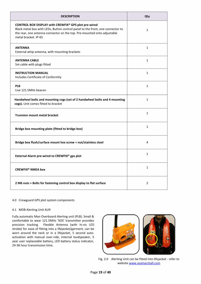
4.1 MOB Alerting Unit AU9
Fully automatic Man Overboard Alerting unit (PLB). Small & comfortable to wear 121.5MHz ‘SOS’ transmitter provides precision tracking. Flexible Antenna (with hi-vis LED strobe) for ease of fitting into a lifejacket/garment, can be worn around the neck or in a lifejacket, 5 second auto-activation with manual over-ride, Internal loudspeaker, 5 year user replaceable battery, LED battery status indicator, 24-36 hour transmission time.
Fig. 2.0 Alerting Unit can be fitted into lifejacket - refer to website www.seamarshall.com

Page 20 of 40
4.2 Crewguard CG-121 MKII (rev.a) pre-wired to Crewfix® NMEA Interface
Dedicated Man Overboard Alarm Base Unit. Automatic immediate MOB alerting. LED MOB warning indicator. Easy to operate and install with user friendly controls. Waterproof IP-67 display. Approximate range indicator (near or far). High quality construction. Training frequencies 121.65MHz & 121.775MHz. 12V Power (24 to 12V DC converter available on request). External siren included for loud audio MOB alerting. Pre-wired to CREWFIX® NMEA GPS output.
Fig. 3.0
4.3 External Antenna for Crewguard CG-121 MKII
External antenna with mounting brackets. Comes with 5m cable and plugs, fitting, mounting bracket. Significantly increases monitoring area of MOB system and provides coverage in radio blind spots.
Fig. 4.0 5.0 Technical Data
Alerting Unit (PLB) – refer to instruction manual supplied with unit
5.1 Crewguard CG-121 MKII
Dimensions 165x95x65mm (excluding antenna & connectors) Weight 500gms Temperature range -20°C + 60°C Waterproofing IP65 Sensitivity 0.5 mV at antenna input Frequencies 121.5 MHz, 121.65 MHz (Test 1), Test 2 (option) Criteria of ELT/PLB recognition Audible AM-modulated howling, downward
LF-range within 300Hz…1600Hz LF-range 700 Hz minimum Time of repetition: 250ms.500ms• DELTA lf/25MS: -10Hz…-250Hz
Audio exit max. 8Vss (speaker > 8 Ohm) Relay contact Floating, carrying capacity max. 0.5 A/10W Current Drain Standby = 80mA /
If alarm + ext. speaker (8 Ohm) = 400mA Operating Voltage 12V DC (+ - 20%)
5.2 Crewfix® NMEA 0183 Interface
Dimensions 65 x 65 x 45mm
Weight ~110g
Temperature Range -20⁰C to 70⁰C
Case rating IP55
Input signal RMC
Output signal GPWPL when MOB RS422
Software Version D1.70.
Current Drain <75mA
Operating Voltage 12V DC
The Crewfix is set to default NMEA-0183 (4800 baud) but can be re-configured for NMEA-0183HS (38400 baud) by request.
Page 21 of 40
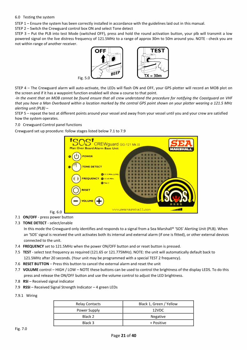
6.0 Testing the system
STEP 1 – Ensure the system has been correctly installed in accordance with the guidelines laid out in this manual. STEP 2 – Switch the Crewguard control box ON and select Tone detect STEP 3 – Put the PLB into test Mode (switched OFF), press and hold the round activation button, your plb will transmit a low powered signal on the live distress frequency of 121.5MHz to a range of approx 30m to 50m around you. NOTE - check you are not within range of another receiver.
Fig. 5.0
STEP 4 – The Crewguard alarm will auto-activate, the LEDs will flash ON and OFF, your GPS plotter will record an MOB plot on the screen and if it has a waypoint function enabled will show a course to that point. -In the event that an MOB cannot be found ensure that all crew understand the procedure for notifying the Coastguard on VHF that you have a Man Overboard within a location marked by the central GPS point shown on your plotter wearing a 121.5 MHz alerting unit (PLB) – STEP 5 – repeat the test at different points around your vessel and away from your vessel until you and your crew are satisfied how the system operates.
7.0 Crewguard Control panel functions
Crewguard set up procedure: follow stages listed below 7.1 to 7.9
Fig. 6.0 7.1 ON/OFF - press power button
7.3 TONE DETECT - select/enable
In this mode the Crewguard only identifies and responds to a signal from a Sea Marshall® ‘SOS’ Alerting Unit (PLB). When
an ‘SOS’ signal is received the unit activates both its internal and external alarm (if one is fitted), or other external devices
connected to the unit.
7.4 FREQUENCY set to 121.5MHz when the power ON/OFF button and or reset button is pressed.
7.5 TEST - select test frequency as required (121.65 or 121.775MHz). NOTE: the unit will automatically default back to
121.5MHz after 20 seconds. (Your unit may be programmed with a special TEST 2 frequency).
7.6 RESET BUTTON – Press this button to cancel the external alarm and reset the unit
7.7 VOLUME control – HIGH / LOW – NOTE these buttons can be used to control the brightness of the display LEDS. To do this
press and release the ON/OFF button and use the volume control to adjust the LED brightness.
7.8 RSI – Received signal indicator
7.9 RSSI – Received Signal Strength Indicator – 4 green LEDs
7.9.1 Wiring
Relay Contacts Black 1, Green / Yellow
Power Supply 12VDC
Black 2 Negative
Black 3 + Positive
Fig. 7.0

Page 22 of 40
8.0 Crewguard CG-121 MKII Installation Guidelines
a. Your unit can be mounted on the metal trunnion mount bracket provided or ‘flush’ mounted into a console.
Fig. 8.0
When installing ensure you leave space for the external antenna cable connection.
Mount the external whip antenna in a good clear position.
Page 23 of 40
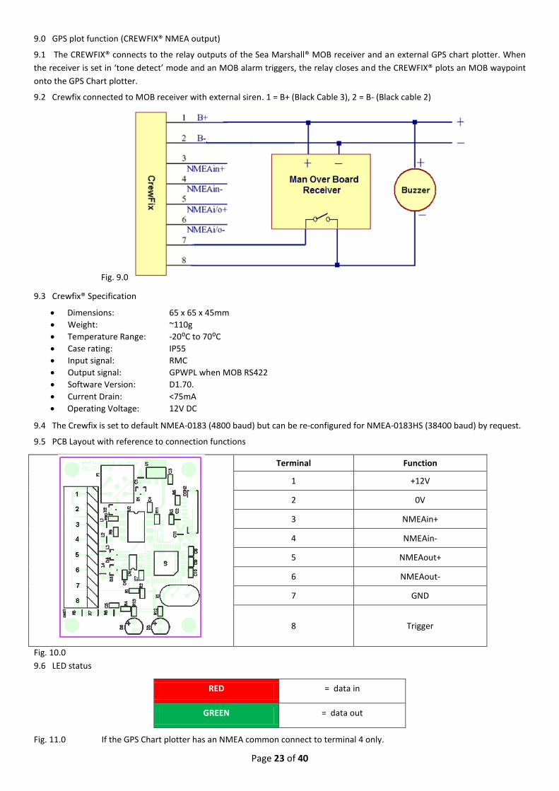
9.0 GPS plot function (CREWFIX® NMEA output)
9.1 The CREWFIX® connects to the relay outputs of the Sea Marshall® MOB receiver and an external GPS chart plotter. When
the receiver is set in ‘tone detect’ mode and an MOB alarm triggers, the relay closes and the CREWFIX® plots an MOB waypoint
onto the GPS Chart plotter.
9.2 Crewfix connected to MOB receiver with external siren. 1 = B+ (Black Cable 3), 2 = B- (Black cable 2)
Fig. 9.0
9.3 Crewfix® Specification
Dimensions: 65 x 65 x 45mm
Weight: ~110g
Temperature Range: -20⁰C to 70⁰C
Case rating: IP55
Input signal: RMC
Output signal: GPWPL when MOB RS422
Software Version: D1.70.
Current Drain: <75mA
Operating Voltage: 12V DC
9.4 The Crewfix is set to default NMEA-0183 (4800 baud) but can be re-configured for NMEA-0183HS (38400 baud) by request.
9.5 PCB Layout with reference to connection functions
Terminal Function
1 +12V
2 0V
3 NMEAin+
4 NMEAin-
5 NMEAout+
6 NMEAout-
7 GND
8 Trigger
Fig. 10.0
9.6 LED status
RED = data in
GREEN = data out
Fig. 11.0 If the GPS Chart plotter has an NMEA common connect to terminal 4 only.
Page 24 of 40
SECTION 3
PRODUCT NAME - CREWGUARD CG-121 MKII man overboard monitor alarm
1.0 Overview
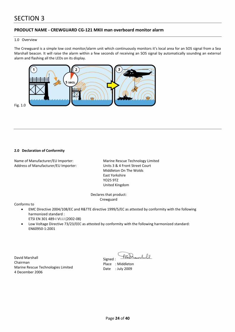
The Crewguard is a simple low cost monitor/alarm unit which continuously monitors it’s local area for an SOS signal from a Sea Marshall beacon. It will raise the alarm within a few seconds of receiving an SOS signal by automatically sounding an external alarm and flashing all the LEDs on its display.
Fig. 1.0
2.0 Declaration of Conformity
Name of Manufacturer/EU Importer: Address of Manufacturer/EU Importer:
Marine Rescue Technology Limited Units 3 & 4 Front Street Court Middleton On The Wolds East Yorkshire YO25 9TZ United Kingdom
Declares that product: Crewguard
Conforms to
EMC Directive 2004/108/EC and R&TTE directive 1999/5/EC as attested by conformity with the following harmonized standard : ETSI EN 301 489-I VI.I.I (2002-08)
Low Voltage Directive 73/23/EEC as attested by conformity with the following harmonized standard: EN60950-1:2001
David Marshall Chairman Marine Rescue Technologies Limited 4 December 2006
Signed : Place : Middleton Date : July 2009

Page 25 of 40
3.0 Parts List
DESCRIPTION Quantity & Part Number
BRIDGE BOX DISPLAY Black metal box with LEDs, Button control panel to the front, one connector to the rear, one antenna connector on the top. Pre-mounted onto adjustable metal bracket. IP-65
1
ANTENNA Rubber duck style antenna (external antennas to extend the monitoring range are available)
1
INSTRUCTION MANUAL Includes Certificate of Conformity
1
Handwheel bolts and mounting cogs (set of 2 handwheel bolts and 4 mounting cogs). Unit comes mounted to adjustable bracket
1
Trunnion mount metal bracket (unit comes prefitted onto this) 1
Bridge box flush/surface mount hex screw + nut/stainless steel 4
External Alarm 1
2 M6 nuts + bolts to mount control box to flat surface 2
4.0 Technical Data - Crewguard CG-121 MKII
Dimensions 165x95x65mm (excluding antenna & connectors)
Weight 500gms
Temperature range -20°C + 60°C
Waterproofing IP65
Sensitivity 0.5 mV at antenna input
Frequencies 121.5 MHz, 121.65 MHz (Test 1), Test 2 (option)
Criteria of ELT/PLB recognition Audible AM-modulated howling, downward
LF-range within 300Hz…1600Hz
LF-range 700 Hz minimum
Time of repetition: 250ms.500ms• DELTA lf/25MS:
-10Hz…-250Hz
Audio exit max. 8Vss (speaker > 8 Ohm)
Relay contact Floating, carrying capacity max. 0.5 A/10W
Current Drain Standby = 80mA /
If alarm + ext. speaker (8 Ohm) = 400mA
Operating Voltage 12V DC (+ - 20%)

Page 26 of 40
5.0 Testing the system
STEP 1 – Ensure the system has been correctly installed in accordance with the guidelines laid out in this manual.
STEP 2 – Switch the Crewguard control box ON and select TONE DETECT
STEP 3 – Put the PLB into test Mode (switched OFF), press and hold the round activation button, your plb will transmit a low
powered signal on the live distress frequency of 121.5MHz to a range of approx 30m to 50m around you. NOTE - check you are
not within range of another receiver.
Fig. 2.0
STEP 4 – The Crewguard alarm will auto-activate, the LEDs will flash ON and OFF
STEP 5 – Press the RESET button to cancel the alarm
In the event that an MOB cannot be found ensure that all crew understand the procedure for notifying the Coastguard on VHF
that you have a Man Overboard within a location marked marked by the central GPS point shown on your plotter wearing a
121.5 MHz alerting unit (PLB) .
STEP 6 – repeat the test at different points around your vessel and away from your vessel until you and your crew are satisfied
how the system operates.
6.0 Crewguard Control panel funtion
To set up your unit for use follow stages 6.1, 6.2 & 6.3 from the list below…running from top left down the display.
Fig. 3.0
6.1 Press ON/OFF power button
6.2 Select/enable TONE DETECT
In this mode the Crewguard only identifies and responds to a signal from a Sea Marshall® ‘SOS’ Alerting Unit (PLB). When an
‘SOS’ signal is received the unit activates both its internal and external alarm (if one fitted), or other external devices connected
to the unit.
6.3 Select FREQUENCY set to 121.5MHz when the unit is powered ON. Select TEST, select test frequency as required (121.65 or
121.775MHz). NOTE: the unit will automatically default back to 121.5MHz after 20 minutes
6.5 RESET BUTTON – Press this button to cancel the external alarm and reset the unit and clear any errors
6.6 VOLUME control – HIGH / LOW – NOTE these buttons can be used to control the brightness of the display LEDS. To do this
press and release the ON/OFF button and use the volume control to adjust the LED brightness.
6.7 RSI – Received signal indicator - this is the RED led/the head of the little orange/red man in the centre of the SOS.
6.8 RSSI – Received Signal Strength Indicator – 4 green LEDs, gives approximate range of target

Page 27 of 40
7.0 Wiring
Relay Contacts Black 1, Green / Yellow
Power Supply 12VDC
Black 2 - Negative
Black 3 + Positive (12V)
Fig. 4.0
8.0 Crewguard CG-121 MKII Installation Guidelines
8.1 Mount the Crewguard in a visible position. Check that the unit can pick up a PLB ‘SOS’ signal from all areas you are looking to provide safety cover for.
Fig. 6.0

Page 28 of 40
SECTION 4
PRODUCT NAME – CREWGUARD LONE WORKER MONITORING SYSTEM (for declaration of conformity refer to individual component products in this manual)
1.0 Overview
The Sea Marshall® Crewguard lone worker monitoring system has been developed to satisfy the need for Man Overboard health and safety cover for organisations which have employees spread out over very large areas ,with individuals often working alone either on or next to water.
At the end of this section are examples of Sea Marshall® lone worker systems currently in use.
1.1 ‘UNMANNED AREA’ CREWGUARD lone worker man overboard MONITORING system
This system is made up of the following components
1 × Cabinet mounted Crewguard CG-121 MKII monitor alarm (with auto-dialler depending on requirment)
1 × High gain external antenna with 20m cables, (plus fixtures and fittings)
Above system inlcudes 2 AU9 plbs as part of the package, 1 live frequency and 1 test frequency
MOB alerting units (beacons) as required (sold separately)
SARfinder® locator unit fitted to workboat (sold separately)
Fig. 2.0 This system provides automatic 24/7 man overboard cover for all types of jetties and large areas of water, it is an automated
version of the above system which uses a telephone auto-dialler (either land-line based or GSM) to notify key persons if
somebody falls overboard.

Page 29 of 40
3.0 Parts List
DESCRIPTION Quantity
Instruction Manual includes DOC
1
Cable-Crewguard CG121MKI External Antenna cable 20m
1
Bridge box display. Black box with leds, button control panel to the front
1
External Alarm 1
Speech Dialler with GSM (mobile) and landline connections (Dialler type dependant on the customers local requirement)
1
Diamond 120/300 MHz airband, fixed station vertical antenna
1
Cabinet enclosure 400 × 300 × 150mm
1
Strobe/Siren Can be externally mounted
1
Bridge box mounting plate 1
Antenna Rubber duck style antenna
1
Bridge box flush/surface mount hex screw + nuts/stainless steel
4
Alerting Units (PLBs) Normally this system comes with 2 Alerting Units, 1 Live 121.5MHz and 1 Test 121.65MHz
2

Page 30 of 40
4.0 Individual system components
4.1 ‘SOS’ transmitter on person
(For further information refer to Alerting Unit handbook)
Fig. 3.0
4.2 Monitor on jetty or control room on platform
The telephone auto-dialler MOB monitor/alarm system. Several telephone numbers can be programmed into the auto-speech dialler. A personalised voice message is recorded onto the auto-dialler by the user; for example “May Day, May Day, May Day, Man Overboard at position 1 …(Position 1 for a system with a single monitor in one location only, position 2 for a system with 2 monitors in different geographic locations…on going as required for systems which have several monitors covering a large geographical area). In the event of a man overboard incident the ‘SOS’ signal from the Alerting Unit worn by the man overboard will trigger the Crewguard MOB monitor alarm which in turn activates the telephone auto-dialler - automatically calling the first member of staff from the pre-programmed list of telephone numbers. A fast rescue craft fitted with a SARfinder® locator unit is then launched to track the ‘SOS’ signal being transmitted by the man overboards plb. Because there may be differences in the type of dialler fitted into the cabinet mounted monitoring system, please refer to the manufacturers instruction manual supplied with your system.
Dimensions – Cabinet Approx. Height = 40cm, Depth = 15cm, Width = 30cm
Weight – Approx. 7.5kg
Temperature Range -20°C + 60°C
Waterproofing IP-65
Power Supply basic system 12V – Cabinet mounted option comes supplied with mains 12V adapter and universal plug fittings.
The cabinet should be mounted in a sheltered location to avoid water ingress.
Fig. 4.0
4.3 Locator unit fitted onto fast rescue craft/workboat
Provides immediate tracking of the person in the water (refer to section 1 of this manual for more details)
Fig. 5.0 5.0 Installing your system If you are installing only the Crewguard monitor refer to the Crewguard installation guide in section 3 of this manual. Technical dimensions for the cabinet mounted version are given under section 4.2 on this page, make sure you use the correct adaptor for your power supply. Mount the antenna in the highest clearest position possible, this will ensure maximum range and no signal blind spots. Below is an example of an external antenna mounted on a control room of a reservoir rangers hut.
Page 31 of 40
Fig. 6.0
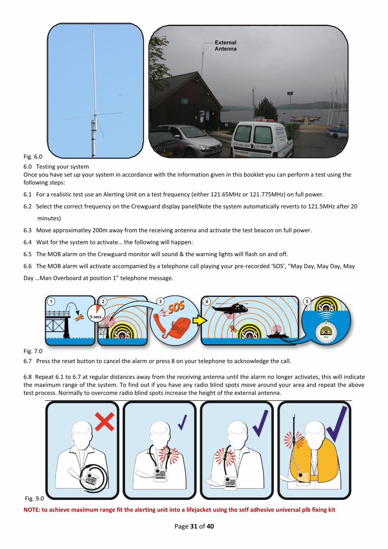
6.0 Testing your system Once you have set up your system in accordance with the information given in this booklet you can perform a test using the following steps:
6.1 For a realistic test use an Alerting Unit on a test frequency (either 121.65MHz or 121.775MHz) on full power.
6.2 Select the correct frequency on the Crewguard display panel(Note the system automatically reverts to 121.5MHz after 20
minutes)
6.3 Move approximatley 200m away from the receiving antenna and activate the test beacon on full power.
6.4 Wait for the system to activate… the following will happen:
6.5 The MOB alarm on the Crewguard monitor will sound & the warning lights will flash on and off.
6.6 The MOB alarm will activate accompanied by a telephone call playing your pre-recorded ‘SOS’, “May Day, May Day, May
Day …Man Overboard at position 1” telephone message.
Fig. 7.0
6.7 Press the reset button to cancel the alarm or press 8 on your telephone to acknowledge the call.
6.8 Repeat 6.1 to 6.7 at regular distances away from the receiving antenna until the alarm no longer activates, this will indicate the maximum range of the system. To find out if you have any radio blind spots move around your area and repeat the above test process. Normally to overcome radio blind spots increase the height of the external antenna.
Fig. 9.0
NOTE: to achieve maximum range fit the alerting unit into a lifejacket using the self adhesive universal plb fixing kit

Page 32 of 40
7.0 PRODUCT EXAMPLES The following pages contain examples of the Sea Marshall® Man Overboard monitoring systems in operation
7.1 RESERVOIRS – inland waterways Carsington Water Reservoir – Peak District, United Kingdom
Fig. 10.0
A Sea Marshall® Crewguard Lone Worker Man Overboard system provides coverage for the whole of Carsington Water (Severn Trent) reservoir shown in the aerial photograph above. Both recreational fishermen and ranger staff are issued with Sea Marshall® alerting units fitted into lifejackets.
Fig. 11.0
7.2 OIL & GAS INDUSTRY Chevron/Texaco Oil Refinery Jetty, Pembrokeshire, South West Wales
Fig. 12.0
As an indication of scale the jetty itself from points 1 through 6 on the aerial photograph is over 3km long and the whole site covers 10 square km. This system has been in place and functioning since 2004. A remote monitoring system is positioned at each of the 6 positions along the jetty indicated on the aerial photograph above. If a man overboard incident occurs an automated telephone message is relayed from the monitors on the jetty to the guard room located at the entrance to the plant. The control room then alerts the rescue crew that a man overboard incident has occurred. The workboat is fitted with a locator unit which is used to track and rescue the man overboard. The control room are also able to notify the local river pilots and coastguards should extra asssitance be required.
Fig. 13.0

Page 33 of 40
7.3 AQUACULTURE – FISH FARMS
Marine Harvest Ireland Marine Harvest Ireland are amongst the first commercial fish farm operators to install a Sea Marshall® lone worker monitoring system to provide 24/7 automatic man overboard cover for their staff.
Fig. 14.0
Fig. 15.0 The cabinet mounted Crewguard monitor is located in a control room on the jetty 250m away from the nearest cage, each member of staff working on the water is fitted with a Sea Marshall® Alerting Unit fitted into a lifejacket.

Page 34 of 40
SECTION 5
PRODUCT NAME - CREWFIX® NMEA box
1.0 Overview
The CREWFIX® NMEA output allows the Sea Marshall® Base Units to automatically output the GPS position of the vessel at the
time an ‘SOS’ incident to takes place giving you a defined reference point to go back to, or to pass on to the Coastguard if
required.
2.0 Technical
The CREWFIX® is connected to the relay outputs of the Crewguard monitor receiver, when the Crewguard is set in ‘tone detect’
mode and an MOB alarm activates/a signal is received, the relay closes. The CREWFIX®, when connected to your GPS,
continuously updates itself with the vessels current position, when a man overboard incident occurs the CREWFIX® outputs the
last recorded postion data as an NMEA command sentence to your GPS plotter instructing it to display the GPS co-ordinates of
the incident on its screen and, if the facility is available, to show a waypoint. To make this unit wateresistant ti should be sealed
with silicon sealant once wired to your external device.
For full technical details of this unit refer to section 1 and 2.

Page 35 of 40
SECTION 6
PRODUCT NAME - SARfinder® transportable system
1.0 Overview
The transportable versions of the SARfinder® locator units are designed to provide temporary cover for users wishing to move
from vessel to vessel. The unit has the control box display and two re-chargeable batteries mounted into a small waterproof
peli-case. Ideal for diver tour operators and dive clubs, or safety vessels moving from site to site. The operation of this system is
the same as the fixed version of the SARfinder®1003 MKII except that the CREWFIX® NMEA plot is not available.
2.0 Declaration Of Conformity
Name of Manufacturer/EU Importer: Address of Manufacturer/EU Importer:
Marine Rescue Technology Limited Units 3 & 4 Front Street Court, Middleton On The Wolds, Driffield, East Yorkshire Y025 9TZ United Kingdom
Declares that product:
SARfinder® GPS Plot Man Overboard Safety System
Conforms to the EMC Directive 2004/108/EC and the R&TTE Directive 1999/5/EC as attested by conformity with the following harmonized standards: ETSI EN 301 489-22 V1.3.1 (2003-11): Electromagnetic compatibility and Radio spectrum Matters (ERM); Electromagnetic Compatibility (EMC) standard for radio equipment and services; Part 22: Specific conditions for ground based VHF aeronautical mobile and fixed radio equipment. ETSI EN 301 489-1 V1.5.1 (2004-11): Electromagnetic compatibility and Radio spectrum Matters (ERM); Electro Magnetic Compatibility (EMC) standard for radio equipment and services; Part 1: Common technical requirements. CREWFIX® EN55022:2006 & EN55024:1998 /A1:2001 /A2:2003 David Marshall Chairman Marine Rescue Technologies Limited 20
th July 2009
Signed : Place : Middleton Date : July 2009

Page 36 of 40
3.0 Parts list
DESCRIPTION Quantity
SPLASH PROOF HOLDALL CARRY CASE For transporting the component parts of the system from area to area
1
SPLASH PROOF SHOULDER BAG For stowing fully assembled transportable SARfinder® ready for rapid deployment
1
BRIDGE BOX DISPLAY Black plastic box with LEDs, button control panel to the front and two connectors to the rear. Mounted into the waterpoof peli case.
1
BRIDGE BOX POWER CABLE Grey power cable with 4 pin connector attached at one end, in line fuse, connects into 4 pin connector. Located on rear of bridge box.
1
ANTENNA White triangular antenna, supplied with 6 gasket rubber rings fitted over the antenna fixing points.
1
ANTENNA HANDLE Poly-prop tube with mounting flange on the top, can be hand held or mounted in a bracket.
1
ANTENNA ELEMENTS Antenna tube/elements × 6 in total. To be screwed onto the antenna fixing points on the body of the antenna. NOTE – 2 OF THESE ARE YELLOW – THESE ARE TO BE FIXED TO THE AHEAD POSITION OF THE ANTENNA next to the ‘AHEAD’ arrow. This is to visually indicate the ahead position of the antenna when the antenna is handheld.
1
ANTENNA CABLE Approx. 10m black RF cable with 7 pin connector fitted at each end, connects the bridge box to the antenna (IP-67 rated connection), each inner wire is marked with a number wiring diagram. Cable has interconnect break at 2m.
1
INSTRUCTION MANUAL Includes Certificate of Conformity
1
PLB Test and training beacons, 1 × live frequency 121.5MHz and 1 × Test frequency
1
Antenna bracket bolts 3
External Alarm Contained inside the PELI case
1
Re-chargeable 12V batteries 2
Battery charger 1

Page 37 of 40
4.0 System components
4.2 Peli-Case mounted version/transportable SARfinder
4.3 Assembly of Transportable SARfinder®
1. Assemble the antenna in accordance with Section 2 of this booklet (NOTE – apply a thin film of silicon grease around the antenna dipole washers instead of silicon adhesive, this will allow you to easily disassemble the antenna when required for transportation). There are two YELLOW dipoles included with the transportable system which are to be fitted to the ahead position of the antenna to provide a quick visual reference as to the AHEAD position of the antenna when the system is being used.
2. Feed the antenna cable through the antenna handle pole and connect to the underside of the antenna.
3. Fix the antenna handle pole to the underside of the antenna with the bolts provided.
4. Open the Peli-Case and connect the battery terminals (red – red, black – black). Close the Peli-Case and re-seal.
5. Switch on to ensure the unit is functioning and perform a quick system test as described on page 14.
The transportable SARfinder® can either be manually carried using the shoulder straps provided as shown in the photo top left; alternatively the control box (Peli-Case) can be positioned in an accessible/visible position on the boat and the antenna held by hand or dropped into a temporary bracket as required. Always ensure the YELLOW dipoles are positioned in the AHEAD direction (bow of boat).
IMPORTANT - If you are relying on the transportable unit for rapid response it is recommended to have the antenna fully
assembled and ready to go. A second bag is included with your system to stow the fully assembled transportable SARfinder.
Put the PELI box display in the bottom of the bag, coil the antenna cable on top of the control box. Put the antenna into the
bag upside down over the top of the PELI case with the handle/pole extending vertically inside the bag. In this configuration
the whole system can be deployed and activated in a few seconds.
4.4 General Operating Points – Transportable Guide (Divers refer to page 38)
For full operating functions refer to section 2, the transportable system operates in the same way as the fixed version with the exception of not having an external NMEA interface.
IMPORTANT - the transportable SARfinder® is normally carried in one of the holdalls provided to be deployed AFTER a man
overboard or lost diver incident has already occurred. The transportable system can, if required, be used to ‘monitor’ for an
MOB or lost diver in the same way that the fixed version of the SARfinder® does. This can be achieved by mounting the
antenna on an external bracket (refer to page 10) and having the PELI/Bridge Control Box mounted in the wheel house with
the control box permanently ON. Refer to section 2 of this manual for guidelines on fixed SARfinder® operation.
Each unit comes supplied with two lead acid re-chargeable 12V batteries and a charger. It is recommended that the battery is recharged after every extended use, rotate the batteries with each use.
The antenna has an arrow etched onto the casing to indicate ahead, there are also two YELLOW dipoles which are to be fitted in the AHEAD position on the antenna; these are to provide a quick visual AHEAD reference when the system is in use.
Always ensure the batteries are charged and ready for use and the system users are fully familiar with the systems operation.
For full SARfinder® operation refer to Section 1.
Check the waterproofing seals on the antenna/cables/Peli-Case on a regular basis.
Page 38 of 40
5. 0 DIVERS using the transportable SARfinder® locating system
To get the maximum tracking range for dive applications where very long range coverage is required the manufacturer
recommends that a fixed version of the SARfinder® is installed on the main dive boat with the SARfinder® antenna mounted high
(1.5 metres) above all metal work and other antennas. This will provide the dive operator with a permanent ‘SOS’ lost diver
tracking system capable of covering the greatest distance. The ideal safety combination for dive applications is to have a fixed
SARfinder® system installed on the main dive boat and a transportable SARfinder® for the small rigid inflatable dive boat.
If you choose to use the SARfinder transportable on its own for lost diver tracking, to achieve the same signal long distance
tracking performance that the fixed version of the SARfinder® will provide, the procedure outlined below must be applied.
In the event that a Diver becomes ‘lost’, in order to achieve the same long distance PLB tracking that a fixed version of the
SARfinder® system would provide, it is necessary to move the transportable SARfinder® antenna to the highest position on the
boat. This will increase the horizon distance over the curvature of the Earth. To do this move the transportable system up to the
highest position on the vessel (the upper sun deck) and position the antenna 1.5 metres above all metal work and other
antennas…it may be necessary to have an extension pole available. BY FOLLOWING THIS PROCEDURE THE TRACKING DISTANCE
OF THE TRANSPORTABLE SYSTEM IS SIGNIFICANTLY INCREASED ALLOWING YOU TO PICK UP AN ‘SOS’ PLB SIGNAL AND
DETERMINE THE DIRECTION OF A LOST DIVER AT A MUCH GREATER RANGE.
THE GREATER THE HEIGHT OF THE TRANSPORTABLE SARfinder® ANTENNA
= INCREASED HORIZON/GREATER TRACKING DISTANCE.
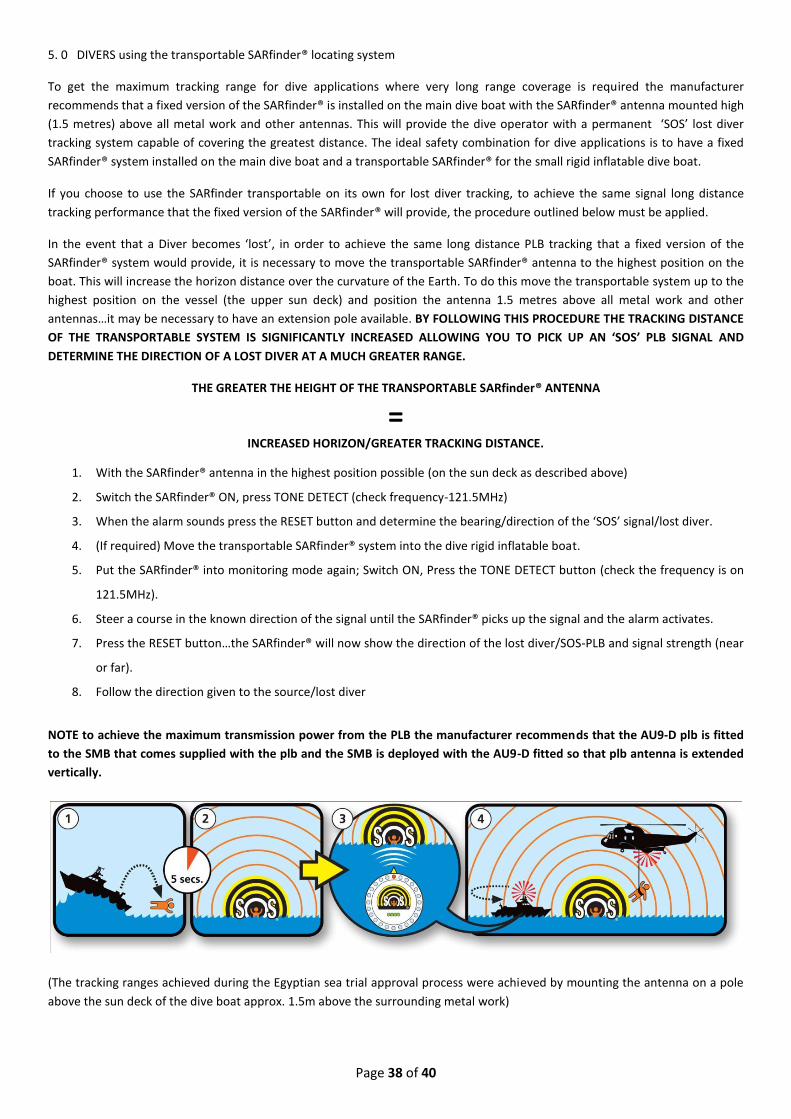
1. With the SARfinder® antenna in the highest position possible (on the sun deck as described above)
2. Switch the SARfinder® ON, press TONE DETECT (check frequency-121.5MHz)
3. When the alarm sounds press the RESET button and determine the bearing/direction of the ‘SOS’ signal/lost diver.
4. (If required) Move the transportable SARfinder® system into the dive rigid inflatable boat.
5. Put the SARfinder® into monitoring mode again; Switch ON, Press the TONE DETECT button (check the frequency is on
121.5MHz).
6. Steer a course in the known direction of the signal until the SARfinder® picks up the signal and the alarm activates.
7. Press the RESET button…the SARfinder® will now show the direction of the lost diver/SOS-PLB and signal strength (near
or far).
8. Follow the direction given to the source/lost diver
NOTE to achieve the maximum transmission power from the PLB the manufacturer recommends that the AU9-D plb is fitted
to the SMB that comes supplied with the plb and the SMB is deployed with the AU9-D fitted so that plb antenna is extended
vertically.
(The tracking ranges achieved during the Egyptian sea trial approval process were achieved by mounting the antenna on a pole
above the sun deck of the dive boat approx. 1.5m above the surrounding metal work)

Page 39 of 40

Page 40 of 40