Embed Size (px)
Citation preview
3D Functional Tolerancing & Annotation
Preface
Using this Guide Where to Find More Information Conventions
What's New
Getting Started
Entering the 3D Functional Tolerancing & Annotation Workbench Choosing the Standard Creating Annotation Texts Creating Simple Datum Creating Datum Targets Creating a Geometrical Tolerance Filtering Annotations Disabling 3D Annotations Accessing the Set Properties
Basic Tasks
Choosing a Standard Using the Tolerancing Advisor
Introducing the Tolerancing Advisor Dimensioning and Tolerancing Threads using the Tolerancing Advisor
Tolerancing Body in White Creating Datum and Datum Targets Creating Dimensions and Associated Datum Creating a Datum Reference Frame Tolerancing Body in White Holes Tolerancing Body in White Surface
Creating Annotations Creating Texts Creating Flag Notes Adding an Attribute Link Creating Datum Creating Datum Targets Creating Geometrical Tolerances Creating Roughness Symbols Creating Isolated Annotations Creating Dimensions Creating Basic Dimensions Creating Coordinate Dimensions Creating Stacked Dimensions Creating Cumulated Dimensions
1Page Functional Tolerancing & Annotation Version 5 Release 13
Creating Curvilinear Dimensions Generating Dimensions Instantiating a Note Object Attribute Creating a Partial Surface Creating a Deviation Creating a Correlated Deviation Creating a Distance Between Two Points
Managing Annotations Selecting Annotation/Annotation Plane Displaying Annotation in the Normal View Moving Annotations Transferring Existing Annotations Transferring Annotations During Creation Grouping Annotations During Creation Grouping Annotations Automatically Grouping and Ordering Annotations Making the Position of a Text Associative Making the Orientation of a Text Associative Mirroring Annotations Clipping Annotations Plane Marking Non-semantic Annotations Setting Annotation Parallel to Screen Replacing a Datum Reference Frame Using 3D Grid
Managing Annotation Leaders Adding Leaders and Using Breakpoints Editing the Shape of an End Manipulator Moving the End Manipulator of a Leader Adding the All Around Symbol Setting Perpendicular a Leader Adding an Interruption Leader
Managing Graphical Properties Setting Basic Graphical Properties Setting Advanced Graphical Properties Setting Graphical Properties as Default Copying Graphical Properties
Filtering Annotations Using Annotation Filters Creating a Tolerancing Capture Displaying a Tolerancing Capture Creating a Camera Managing Tolerancing Capture Options Using Capture Management
View/Annotation Planes Using a View/Annotation Plane Creating a Projection View/Annotation Plane Creating a Section View/Annotation Plane Creating a Section Cut View/Annotation Plane Creating an Aligned Section View/Section Cut Creating an Offset Section View/Section Cut
2Page Functional Tolerancing & Annotation Version 5 Release 13
Activating a View/Annotation Plane Editing View/Annotation Plane Properties Managing View/Annotation Plane Associativity
Migrating V4 FD&T Data
Advanced Tasks
Creating Note Object Attribute Note Object Attribute From a Text Note Object Attribute From a Ditto Storing a Note Object Attribute into a Catalog
Managing Annotation Connection Using the Scope Range Adding Geometry Adding Component
Re-specifying Geometry Canonicity Reporting Annotations
Generating a Check Report Customizing the Reporting
Annotation Associativity Querying 3D Annotations Creating an Automatic Default Annotation
Managing Power Copies Creating Power Copy Instantiating Power Copy Saving Power Copy into a Catalog
Providing Constructed Geometry for 3D Annotations Creating an Automatic Constructed Geometry Managing Constructed Geometry
Interoperability
Optimal CATIA PLM Usability for Functional Tolerancing & Annotation
Workbench Description
Menu Bar Insert Views/Annotation Planes Menu Insert -> Annotations Menu Insert -> Advanced Replication Tools Menu
Annotations Toolbar Dimension Properties Toolbar Reporting Toolbar Style Toolbar Text Properties Toolbar Position and Orientation Toolbar Views/Annotation Planes Toolbar Check Toolbar Note Object Attribute Toolbar 3D Grid Toolbar Grouping Toolbar Capture Toolbar Geometry for 3D Annotations Toolbar Deviations Toolbar (Compact) Workshop Description
3Page Functional Tolerancing & Annotation Version 5 Release 13
Workbench Toolbar Capture Visualization Toolbar Capture Options Toolbar Camera Toolbar
Customizing for 3D Functional Tolerancing & Annotation
Tolerancing Display Constructed Geometry Manipulators Dimension Annotation Tolerances View/Annotation Plane
Reference Information
Standards Dimension Tolerance Display Dimension Numerical Display
Semantic Support Normative References Principles and Fundamental Rules for Geometrical Tolerancing Geometrical Tolerancing Symbols for Geometrical Tolerances Symbols for Modifiers Datum Principles Concepts
3D Annotations and Annotation Planes Non-semantic and Semantic Usage Note Object Attribute
Properties Text Graphical Properties Text Properties Toolbar Semantic Numerical Display Properties Annotation Set Detail Properties
Dimension Units Statistic Laws
Normal Law Uniform Law Constant Law Pearson Law Poisson Law Snedecor Law
Glossary
Index
4Page Functional Tolerancing & Annotation Version 5 Release 13
Preface3D Functional Tolerancing & Annotation is a new-generation product which lets you easily define and manage 3D tolerance specifications and annotations directly on 3D parts or products.
The intuitive interface of the product provides an ideal solution for new application customers in small and medium-size industries, looking to reduce reliance on 2D drawings, and increase the use of 3D as the master representation for driving from design to manufacturing engineering process.
Annotations in 3D Functional Tolerancing & Annotation can be extracted, using the annotation plane concept in the Generative Drafting product.
The product elements can be reviewed using specific functionalities, which constitute comprehensive tools for the interpretation of tolerancing annotations.
This manual is intended for users who need to specify tolerancing annotations on 3D parts or on 3D products. It assists designers in assigning the correct tolerances on the selected surfaces by:
● Selecting the surfaces to be toleranced.
● Choosing among the available options, the tolerance types, the modifiers, etc. The system offers a choice of options which are consistent with the selected surfaces.
● Entering the tolerance value. The tolerance annotation is then created and displayed around the 3D geometry. It is also located and oriented in an annotation plane, using a standardized model (usual standards: ISO, ASME / ANSI).
As a consequence, designers do not need to wonder whether the tolerancing syntax is correct, because this syntax is directly elaborated with regard to the chosen tolerancing standards (ISO, ASME / ANSI).
Designers are ensured that their tolerancing schema is consistent with the part geometry. They do not need to be tolerancing experts, having in mind all the complex standardized tolerancing rules. Moreover, the tolerancing specifications will remain consistent whatever the geometrical modifications are.
See Reference Information for further detail.
Note that 3 workbenches are available depending on whether you are working on a part (Functional Tolerancing and Annotation workbench), a product (Product Functional Tolerancing and Annotation workbench) or a process (Process Tolerancing and Annotation workbench). This guide is intended for users of all 3 workbenches, as the functionalities available are exactly the same from one workbench to another. However, note that the scenarios provided in this guide use parts (CATPart documents) as examples.
Using this GuideWhere to Find More Information
Conventions
5Page Functional Tolerancing & Annotation Version 5 Release 13
Using this Guide
This guide is intended for the user who needs to become quickly familiar with the Functional Tolerancing and Annotation, Product Functional Tolerancing and Annotation and Process Tolerancing and Annotation workbenches.
Note that the functionalities available are exactly the same from one workbench to another, even though the scenarios provided in this guide use parts (CATPart documents) as examples.
Before reading this guide, the user should be familiar with basic Version 5 concepts such as document windows, standard and view toolbars.
To get the most out of this guide, we suggest you start reading and performing the step-by-step tutorial Getting Started. Once you have finished, you should move on to the next sections, where you will find detailed explanations regarding the handling of the product. You can also take a look at the Workbench Description section describing the workbench.
To perform the scenarios, you will use sample documents contained in the C:\Program Files\Dassault Systemes\Bxxdoc\English\online\fdtug\samples folder (where xx in Bxxdoc stands for the current release number). For more information on accessing sample documents, refer to Accessing Sample Documents in the Infrastructure User's Guide.
6Page Functional Tolerancing & Annotation Version 5 Release 13
Where to Find More InformationPrior to reading this book, we recommend that you read Infrastructure User's Guide.
Part Design User's Guide as well as Generative Drafting User's Guide may prove useful too.Certain conventions are used in V5 documentation to help you recognize and understand important concepts and specifications.
7Page Functional Tolerancing & Annotation Version 5 Release 13
ConventionsCertain conventions are used in CATIA, ENOVIA & DELMIA documentation to help you recognize and understand important concepts and specifications.
Graphic Conventions
The three categories of graphic conventions used are as follows:
● Graphic conventions structuring the tasks
● Graphic conventions indicating the configuration required
● Graphic conventions used in the table of contents
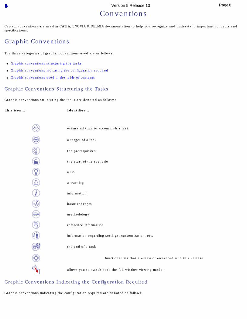
Graphic Conventions Structuring the Tasks
Graphic conventions structuring the tasks are denoted as follows:
This icon... Identifies...
estimated time to accomplish a task
a target of a task
the prerequisites
the start of the scenario
a tip
a warning
information
basic concepts
methodology
reference information
information regarding settings, customization, etc.
the end of a task
functionalities that are new or enhanced with this Release.
allows you to switch back the full-window viewing mode.
Graphic Conventions Indicating the Configuration Required
Graphic conventions indicating the configuration required are denoted as follows:
8Page Functional Tolerancing & Annotation Version 5 Release 13
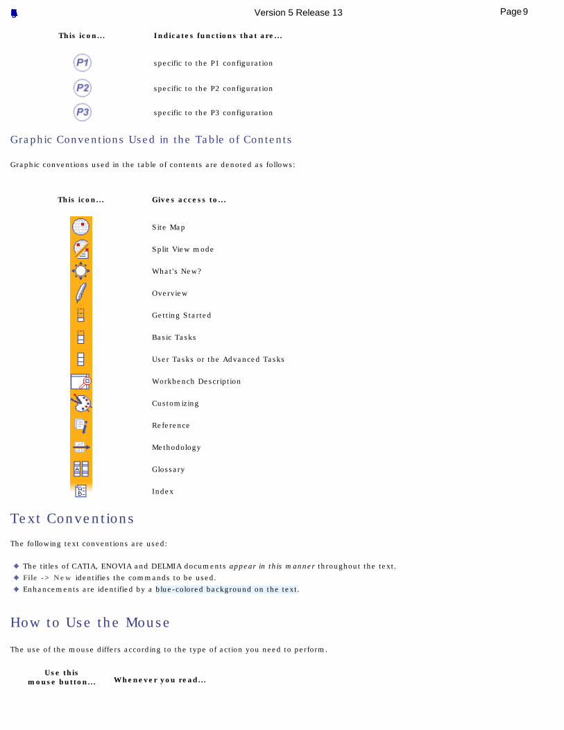
This icon... Indicates functions that are...
specific to the P1 configuration
specific to the P2 configuration
specific to the P3 configuration
Graphic Conventions Used in the Table of Contents
Graphic conventions used in the table of contents are denoted as follows:
This icon... Gives access to...
Site Map
Split View mode
What's New?
Overview
Getting Started
Basic Tasks
User Tasks or the Advanced Tasks
Workbench Description
Customizing
Reference
Methodology
Glossary
Index
Text Conventions
The following text conventions are used:
The titles of CATIA, ENOVIA and DELMIA documents appear in this manner throughout the text. File -> New identifies the commands to be used. Enhancements are identified by a blue-colored background on the text.
How to Use the Mouse
The use of the mouse differs according to the type of action you need to perform.
Use thismouse button... Whenever you read...
9Page Functional Tolerancing & Annotation Version 5 Release 13
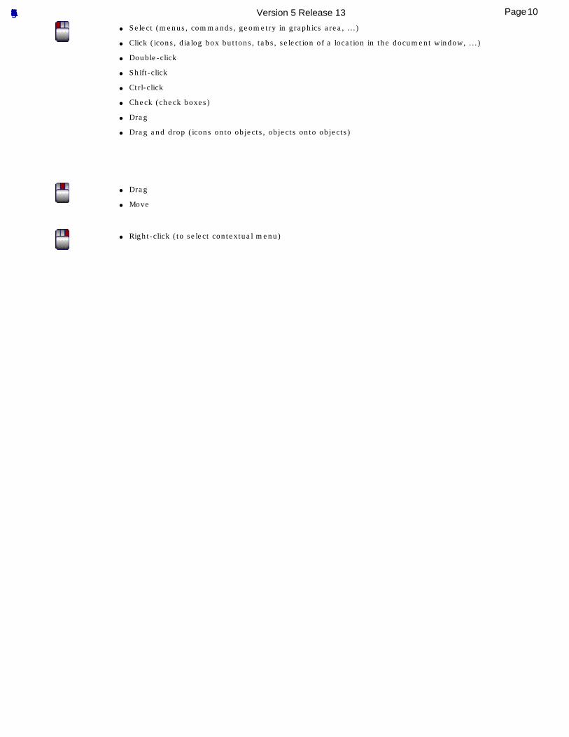
● Select (menus, commands, geometry in graphics area, ...)
● Click (icons, dialog box buttons, tabs, selection of a location in the document window, ...)
● Double-click
● Shift-click
● Ctrl-click
● Check (check boxes)
● Drag
● Drag and drop (icons onto objects, objects onto objects)
● Drag
● Move
● Right-click (to select contextual menu)
10Page Functional Tolerancing & Annotation Version 5 Release 13
What's New?
New Functionalities
Semantic SupportSupport of oriented dimensions (dimensional limits related to an origin).
Optimal CATIA PLM Usability for Functional Tolerancing & Annotation Safe save mode to ensure that data created in CATIA V5 can be correctly saved in ENOVIA V5.
DisplayNew option: 3D Annotation Query.
DimensionNew options: Line-Up and Dimension related to an origin.
Enhanced Functionalities
Creating Roughness SymbolsNew roughness symbol, extension line for roughness positioned out of the geometry and JIS standard support.
11Page Functional Tolerancing & Annotation Version 5 Release 13
Getting Started
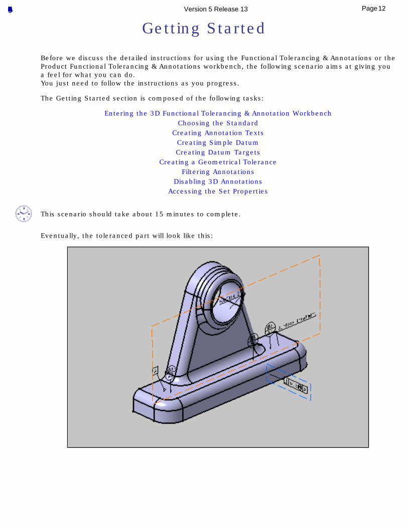
Before we discuss the detailed instructions for using the Functional Tolerancing & Annotations or the Product Functional Tolerancing & Annotations workbench, the following scenario aims at giving you a feel for what you can do.You just need to follow the instructions as you progress.
The Getting Started section is composed of the following tasks:
Entering the 3D Functional Tolerancing & Annotation WorkbenchChoosing the Standard
Creating Annotation TextsCreating Simple DatumCreating Datum Targets
Creating a Geometrical ToleranceFiltering Annotations
Disabling 3D AnnotationsAccessing the Set Properties
This scenario should take about 15 minutes to complete.
Eventually, the toleranced part will look like this:
12Page Functional Tolerancing & Annotation Version 5 Release 13
Entering the 3D Functional Tolerancing & Annotation Workbench
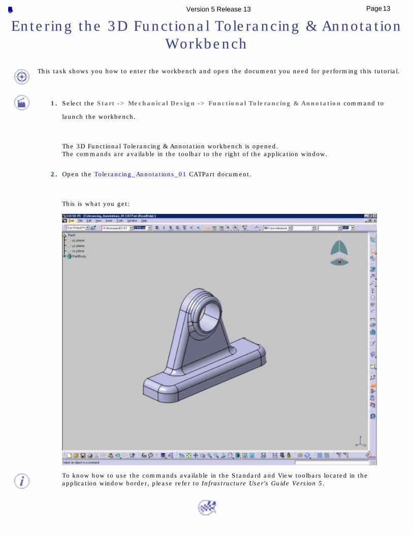
This task shows you how to enter the workbench and open the document you need for performing this tutorial.
1. Select the Start -> Mechanical Design -> Functional Tolerancing & Annotation command to
launch the workbench.
The 3D Functional Tolerancing & Annotation workbench is opened.The commands are available in the toolbar to the right of the application window.
2. Open the Tolerancing_Annotations_01 CATPart document.
This is what you get:
To know how to use the commands available in the Standard and View toolbars located in the application window border, please refer to Infrastructure User's Guide Version 5.
13Page Functional Tolerancing & Annotation Version 5 Release 13
Choosing the Standard
This task shows you how to set the standard you need for tolerancing your part.
You must choose a standard before creating the first annotation in a document. See also Standards.
1. Select the Tools -> Options command.
The Options dialog box is displayed
2. Click Mechanical Design then Functional Tolerancing in the left-hand column.
See Tolerancing setting for further detail.
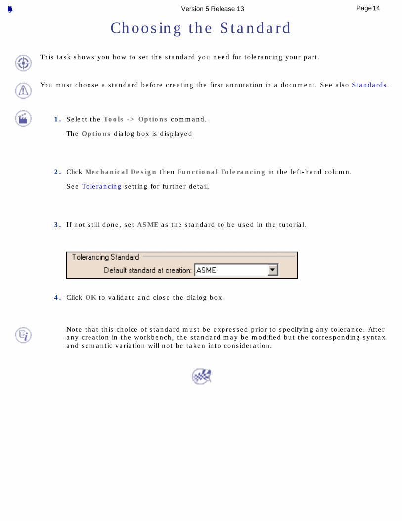
3. If not still done, set ASME as the standard to be used in the tutorial.
4. Click OK to validate and close the dialog box.
Note that this choice of standard must be expressed prior to specifying any tolerance. After any creation in the workbench, the standard may be modified but the corresponding syntax and semantic variation will not be taken into consideration.
14Page Functional Tolerancing & Annotation Version 5 Release 13
Creating Annotation Texts
This task shows you how to create two textual annotations related to the 3D geometry of the part.
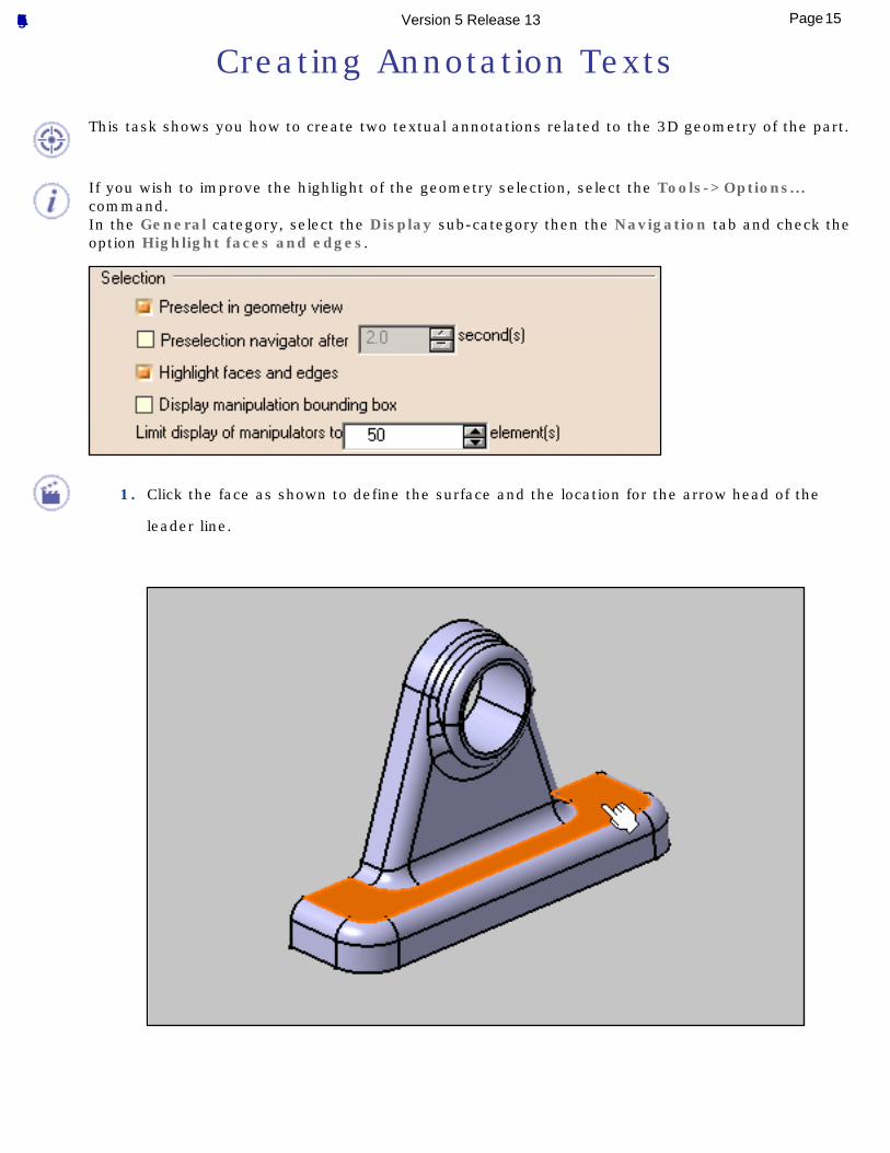
If you wish to improve the highlight of the geometry selection, select the Tools->Options... command.In the General category, select the Display sub-category then the Navigation tab and check the option Highlight faces and edges.
1. Click the face as shown to define the surface and the location for the arrow head of the
leader line.
15Page Functional Tolerancing & Annotation Version 5 Release 13
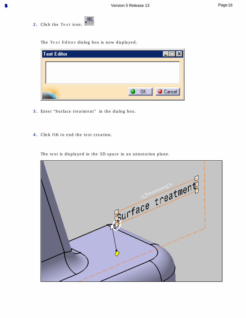
2. Click the Text icon:
The Text Editor dialog box is now displayed.
3. Enter "Surface treatment" in the dialog box.
4. Click OK to end the text creation.
The text is displayed in the 3D space in an annotation plane.
16Page Functional Tolerancing & Annotation Version 5 Release 13
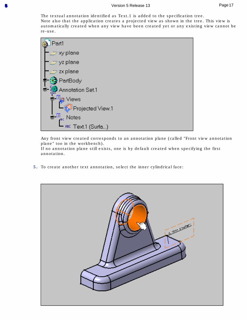
The textual annotation identified as Text.1 is added to the specification tree.Note also that the application creates a projected view as shown in the tree. This view is automatically created when any view have been created yet or any existing view cannot be re-use.
Any front view created corresponds to an annotation plane (called "Front view annotation plane" too in the workbench).If no annotation plane still exists, one is by default created when specifying the first annotation.
5. To create another text annotation, select the inner cylindrical face:
17Page Functional Tolerancing & Annotation Version 5 Release 13
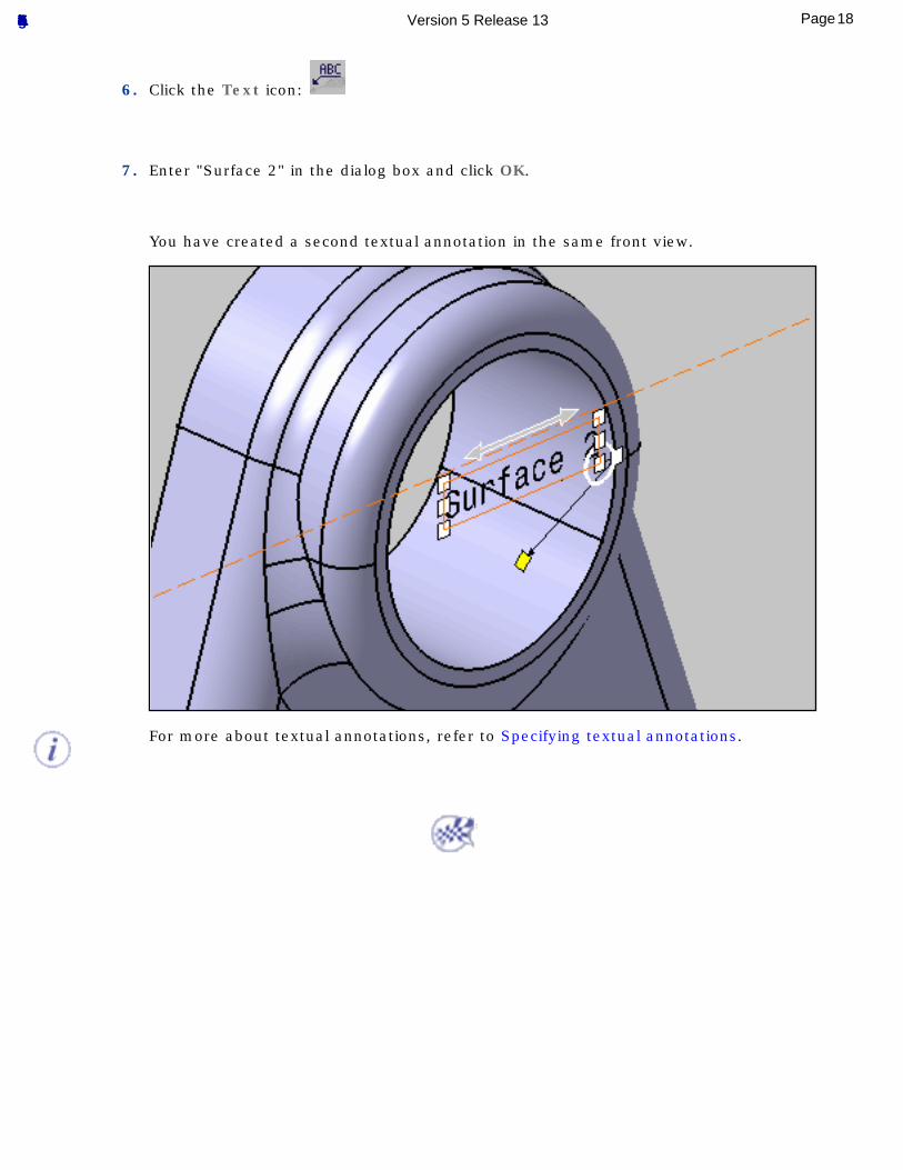
6. Click the Text icon:
7. Enter "Surface 2" in the dialog box and click OK.
You have created a second textual annotation in the same front view.
For more about textual annotations, refer to Specifying textual annotations.
18Page Functional Tolerancing & Annotation Version 5 Release 13
Creating Simple Datum
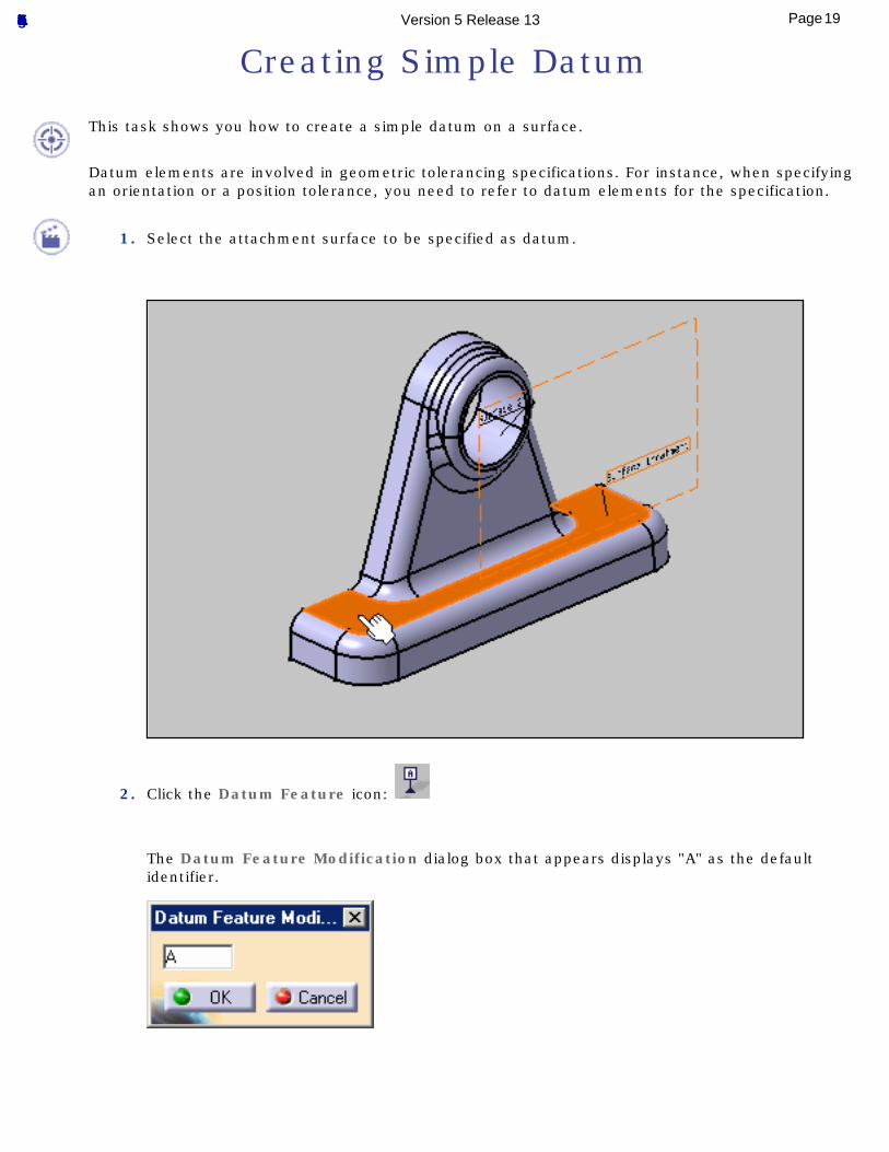
This task shows you how to create a simple datum on a surface.
Datum elements are involved in geometric tolerancing specifications. For instance, when specifying an orientation or a position tolerance, you need to refer to datum elements for the specification.
1. Select the attachment surface to be specified as datum.
2. Click the Datum Feature icon:
The Datum Feature Modification dialog box that appears displays "A" as the default identifier.
19Page Functional Tolerancing & Annotation Version 5 Release 13
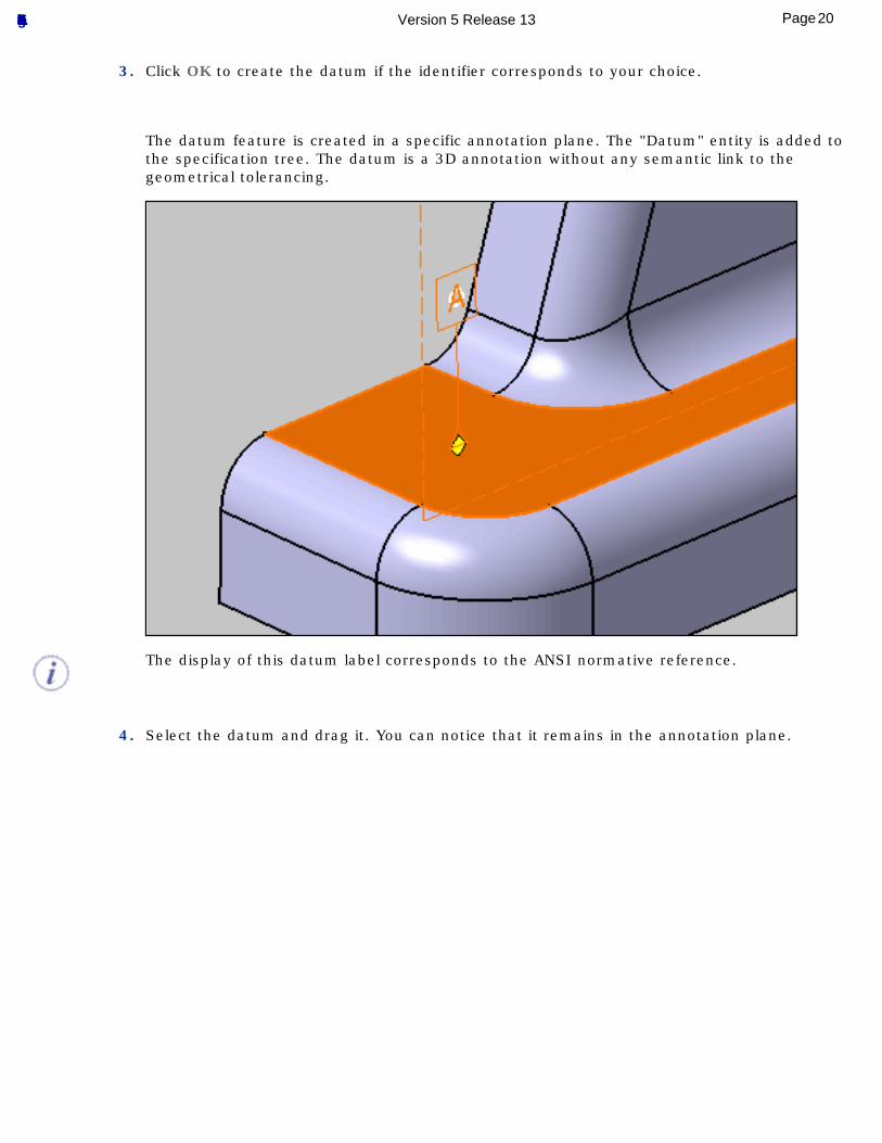
3. Click OK to create the datum if the identifier corresponds to your choice.
The datum feature is created in a specific annotation plane. The "Datum" entity is added to the specification tree. The datum is a 3D annotation without any semantic link to the geometrical tolerancing.
The display of this datum label corresponds to the ANSI normative reference.
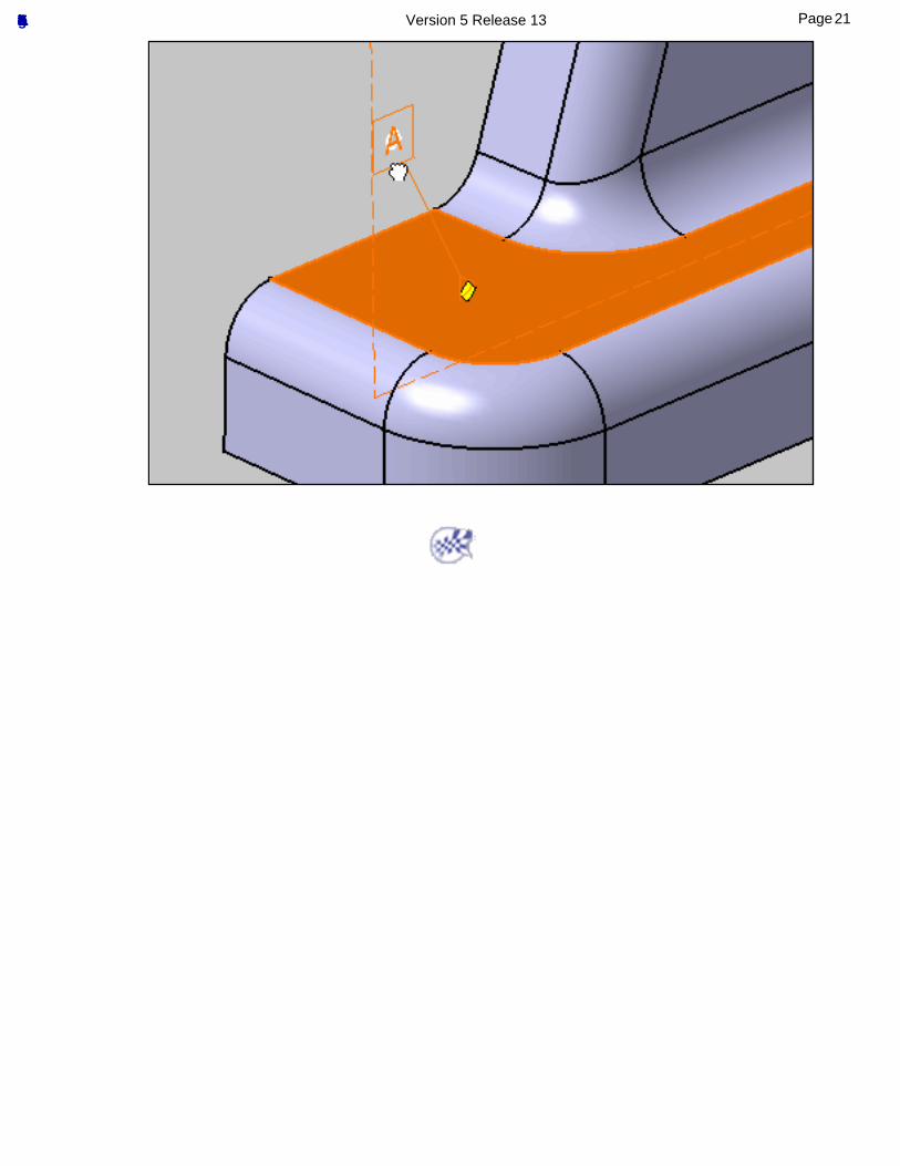
4. Select the datum and drag it. You can notice that it remains in the annotation plane.
20Page Functional Tolerancing & Annotation Version 5 Release 13
21Page Functional Tolerancing & Annotation Version 5 Release 13
Creating Datum Targets
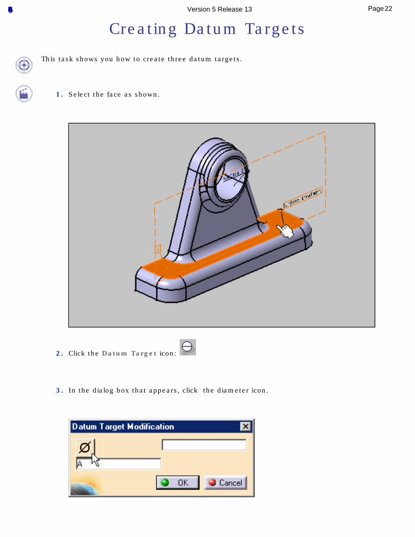
This task shows you how to create three datum targets.
1. Select the face as shown.
2. Click the Datum Target icon:
3. In the dialog box that appears, click the diameter icon.
22Page Functional Tolerancing & Annotation Version 5 Release 13
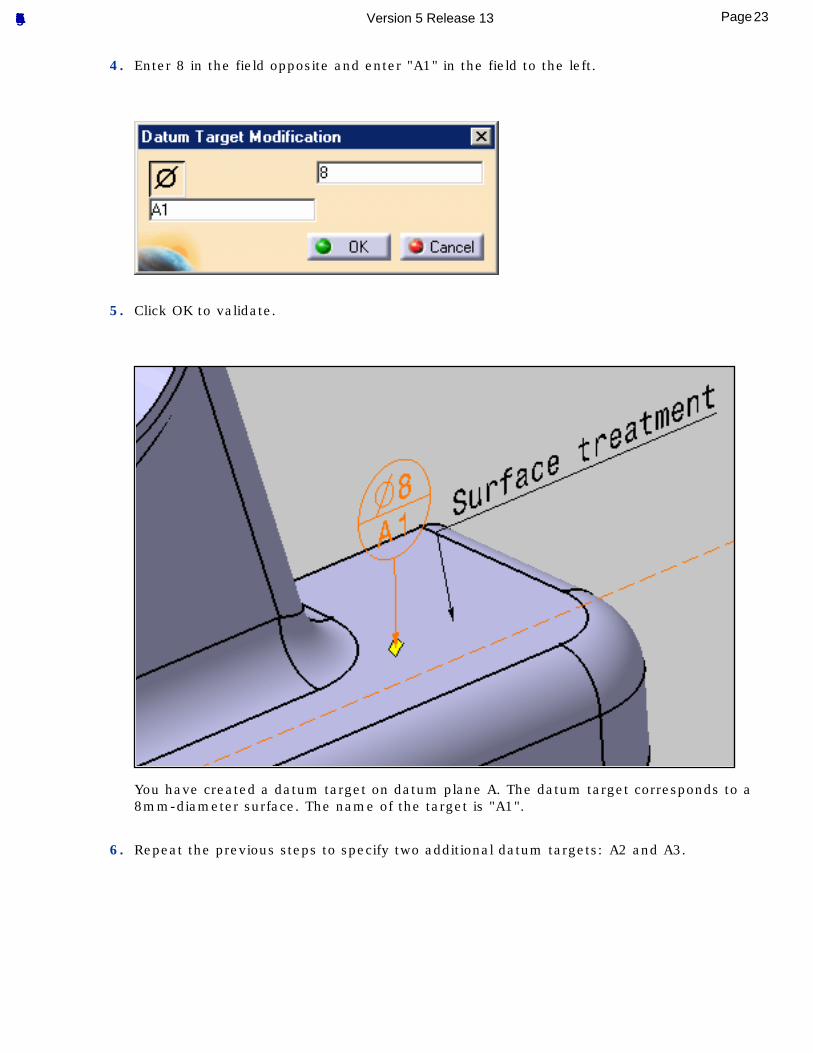
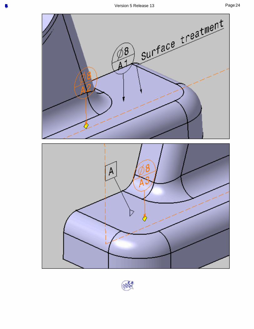
4. Enter 8 in the field opposite and enter "A1" in the field to the left.
5. Click OK to validate.
You have created a datum target on datum plane A. The datum target corresponds to a 8mm-diameter surface. The name of the target is "A1".
6. Repeat the previous steps to specify two additional datum targets: A2 and A3.
23Page Functional Tolerancing & Annotation Version 5 Release 13
24Page Functional Tolerancing & Annotation Version 5 Release 13
Creating a Geometrical Tolerance
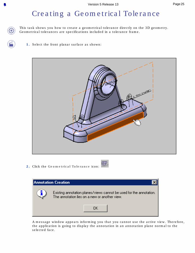
This task shows you how to create a geometrical tolerance directly on the 3D geometry.Geometrical tolerances are specifications included in a tolerance frame.
1. Select the front planar surface as shown:
2. Click the Geometrical Tolerance icon:
A message window appears informing you that you cannot use the active view. Therefore, the application is going to display the annotation in an annotation plane normal to the selected face.
25Page Functional Tolerancing & Annotation Version 5 Release 13
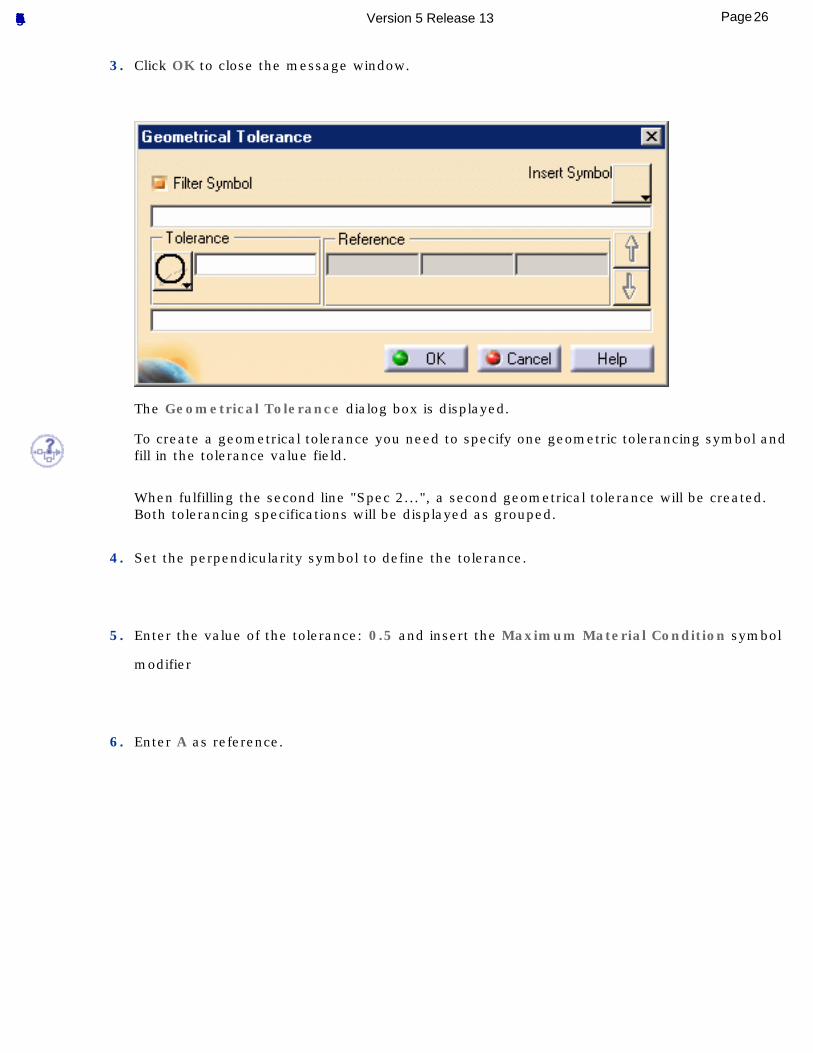
3. Click OK to close the message window.
The Geometrical Tolerance dialog box is displayed.
To create a geometrical tolerance you need to specify one geometric tolerancing symbol and fill in the tolerance value field.
When fulfilling the second line "Spec 2...", a second geometrical tolerance will be created.Both tolerancing specifications will be displayed as grouped.
4. Set the perpendicularity symbol to define the tolerance.
5. Enter the value of the tolerance: 0.5 and insert the Maximum Material Condition symbol
modifier
6. Enter A as reference.
26Page Functional Tolerancing & Annotation Version 5 Release 13
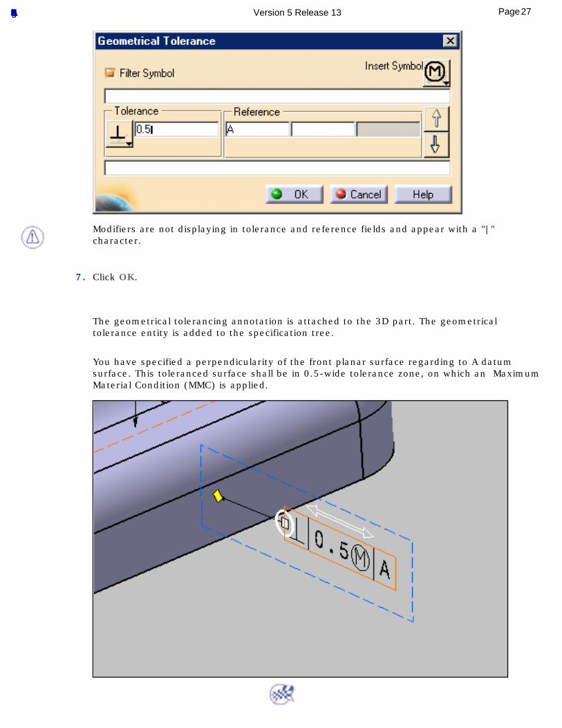
Modifiers are not displaying in tolerance and reference fields and appear with a "|" character.
7. Click OK.
The geometrical tolerancing annotation is attached to the 3D part. The geometrical tolerance entity is added to the specification tree.
You have specified a perpendicularity of the front planar surface regarding to A datum surface. This toleranced surface shall be in 0.5-wide tolerance zone, on which an Maximum Material Condition (MMC) is applied.
27Page Functional Tolerancing & Annotation Version 5 Release 13
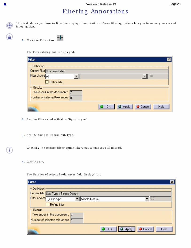
Filtering Annotations
This task shows you how to filter the display of annotations. These filtering options lets you focus on your area of investigation.
1. Click the Filter icon:
The Filter dialog box is displayed.
2. Set the Filter choice field to "By sub-type".
3. Set the Simple Datum sub-type.
Checking the Refine filter option filters out tolerances still filtered.
4. Click Apply.
The Number of selected tolerances field displays "1".
28Page Functional Tolerancing & Annotation Version 5 Release 13
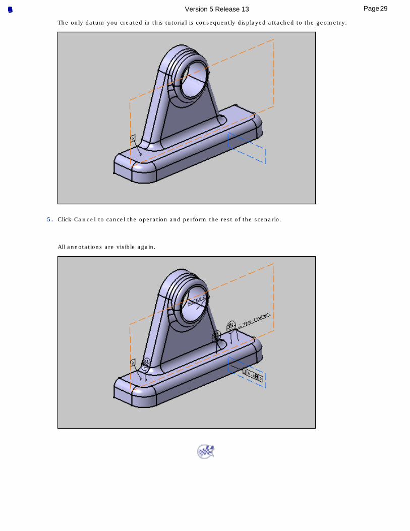
The only datum you created in this tutorial is consequently displayed attached to the geometry.
5. Click Cancel to cancel the operation and perform the rest of the scenario.
All annotations are visible again.
29Page Functional Tolerancing & Annotation Version 5 Release 13
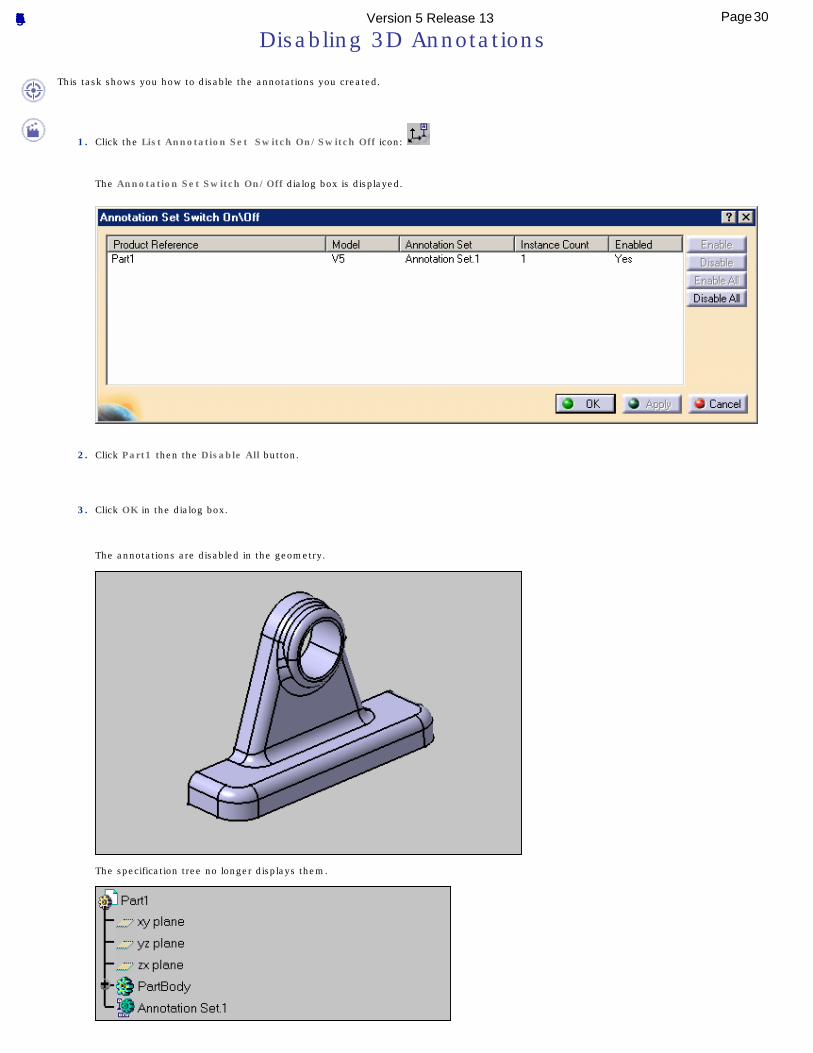
Disabling 3D Annotations
This task shows you how to disable the annotations you created.
1. Click the List Annotation Set Switch On/Switch Off icon:
The Annotation Set Switch On/Off dialog box is displayed.
2. Click Part1 then the Disable All button.
3. Click OK in the dialog box.
The annotations are disabled in the geometry.
The specification tree no longer displays them.
30Page Functional Tolerancing & Annotation Version 5 Release 13
4. Click the List Annotation Set Switch On/Switch Off icon again to restore the previous state.
5. Click Part1 then the Enable All button.
31Page Functional Tolerancing & Annotation Version 5 Release 13
Accessing the Set Properties
This task shows you how to access the set properties and edit the set name.
1. Select Annotation Set.1 in the specification tree.
2. Right-click and select the Properties contextual command.
3. Click Tolerancing & Annotations tab.
The dialog box that appears displays information about the set, namely:
The selected set name: as displayed in the specification tree
The standard used: ANSI
The number of specifications: you have created seven specifications.
The detail of these specifications: you have created two textual annotations, three datum targets, one GD&T and one datum.
32Page Functional Tolerancing & Annotation Version 5 Release 13
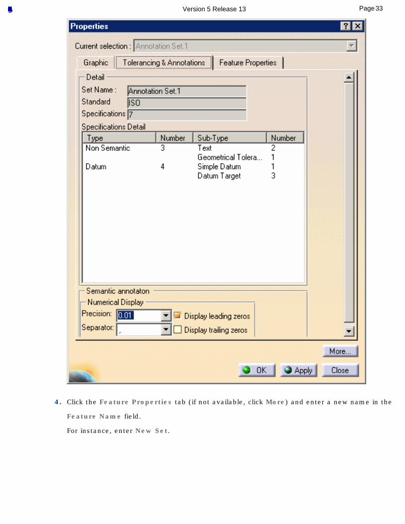
4. Click the Feature Properties tab (if not available, click More) and enter a new name in the
Feature Name field.
For instance, enter New Set.
33Page Functional Tolerancing & Annotation Version 5 Release 13
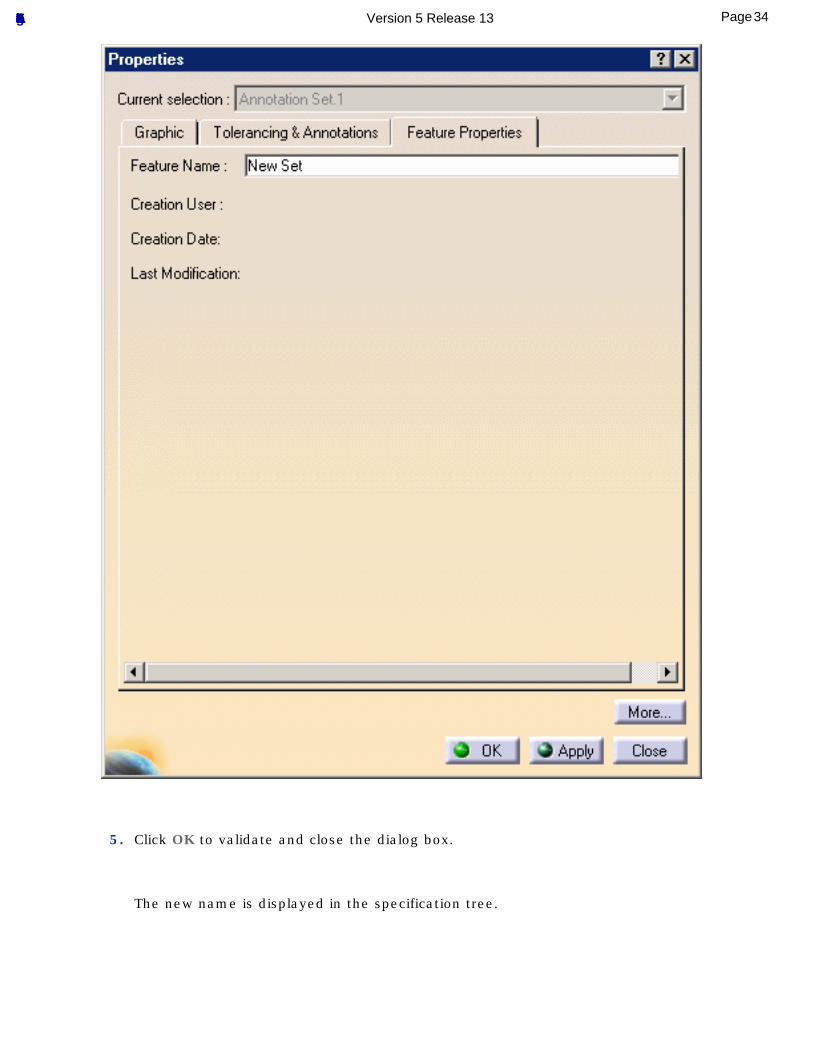
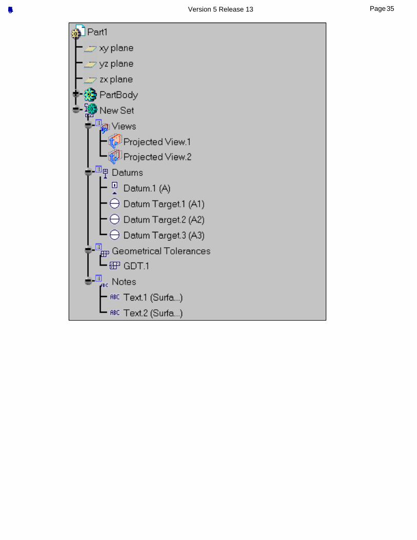
5. Click OK to validate and close the dialog box.
The new name is displayed in the specification tree.
34Page Functional Tolerancing & Annotation Version 5 Release 13
35Page Functional Tolerancing & Annotation Version 5 Release 13

Basic Tasks3D Functional Tolerancing & Annotation allows you to perform the following basic tasks:
[Choosing a Standard][Using the Tolerancing Advisor]
[Tolerancing Body in White][Creating Annotations][Managing Annotations]
[Managing Annotation Leaders][Managing Graphical Properties]
[Filtering Annotations][View/Annotation Planes][Migrating V4 FD&T Data]
36Page Functional Tolerancing & Annotation Version 5 Release 13
Choosing a Standard
This task shows you how to set the standard you need for tolerancing your part or assembly.
You must choose a standard before creating the first annotation in a document. See also Standards.
1. Select the Tools -> Options command.
The Options dialog box is displayed
2. Click Mechanical Design then Functional Tolerancing in the left-hand column.
The Default standard at creation option provides five conventional standards:
● ASME (American Society for Mechanical Engineers)
● ASME 3D (American Society for Mechanical Engineers)
● ANSI (American National Standards Institute)
● ISO (International Organization for Standardization)
● JIS (Japanese Industrial Standard)
See Tolerancing setting for further detail.
3. Click OK to validate and close the dialog box.
Note that this choice of standard must be expressed prior to specifying any tolerance. After any creation in the workbench, the standard may be modified but the corresponding syntax and semantic variation will not be taken into consideration.
37Page Functional Tolerancing & Annotation Version 5 Release 13
Using the Tolerancing Advisor
Introducing the Tolerancing Advisor: get started with the Tolerancing Advisor.
Dimensioning and Tolerancing Threads using the Tolerancing Advisor: see how the Tolerancing Advisor lets you create dimensions and tolerances for threads.
38Page Functional Tolerancing & Annotation Version 5 Release 13
Introducing the Tolerancing Advisor
This task introduces the Tolerancing Advisor.
The Tolerancing Advisor lets you create allowed annotations according to the selected geometrical element or existing annotation.
Allowed annotations are:● Semantic and non semantic annotations (Text, Roughness, Flag note). See Tolerancing Settings.
● Datum.
● Datum target.
● Datum reference frame.
Open the Tolerancing_Annotations_01 CATPart document.
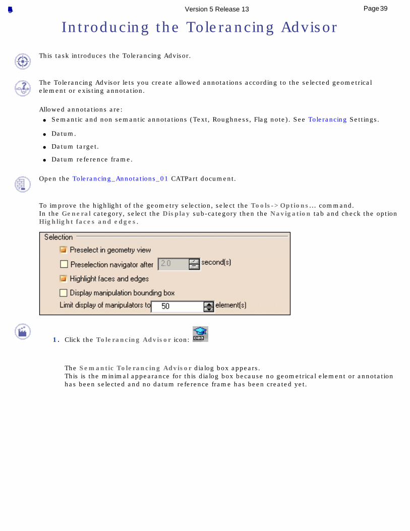
To improve the highlight of the geometry selection, select the Tools->Options... command.In the General category, select the Display sub-category then the Navigation tab and check the option Highlight faces and edges.
1. Click the Tolerancing Advisor icon:
The Semantic Tolerancing Advisor dialog box appears.This is the minimal appearance for this dialog box because no geometrical element or annotation has been selected and no datum reference frame has been created yet.
39Page Functional Tolerancing & Annotation Version 5 Release 13
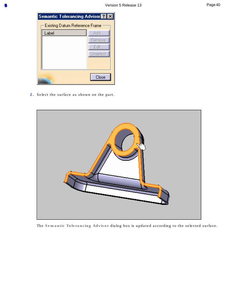
2. Select the surface as shown on the part.
The Semantic Tolerancing Advisor dialog box is updated according to the selected surface.
40Page Functional Tolerancing & Annotation Version 5 Release 13
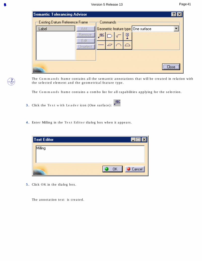
The Commands frame contains all the semantic annotations that will be created in relation with the selected element and the geometrical feature type.
The Commands frame contains a combo list for all capabilities applying for the selection.
3. Click the Text with Leader icon (One surface):
4. Enter Milling in the Text Editor dialog box when it appears.
5. Click OK in the dialog box.
The annotation text is created.
41Page Functional Tolerancing & Annotation Version 5 Release 13
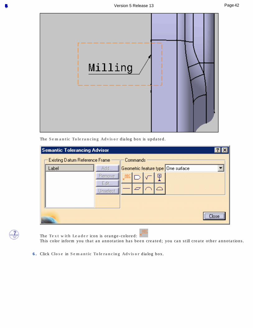
The Semantic Tolerancing Advisor dialog box is updated.
The Text with Leader icon is orange-colored: This color inform you that an annotation has been created; you can still create other annotations.
6. Click Close in Semantic Tolerancing Advisor dialog box.
42Page Functional Tolerancing & Annotation Version 5 Release 13
Dimensioning and Tolerancing Threads using the Tolerancing Advisor
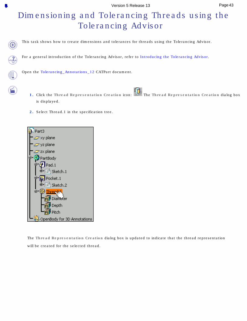
This task shows how to create dimensions and tolerances for threads using the Tolerancing Advisor.
For a general introduction of the Tolerancing Advisor, refer to Introducing the Tolerancing Advisor.
Open the Tolerancing_Annotations_12 CATPart document.
1. Click the Thread Representation Creation icon: The Thread Representation Creation dialog box
is displayed.
2. Select Thread.1 in the specification tree.
The Thread Representation Creation dialog box is updated to indicate that the thread representation
will be created for the selected thread.
43Page Functional Tolerancing & Annotation Version 5 Release 13
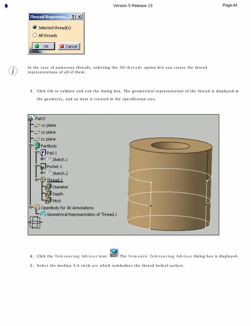
In the case of numerous threads, selecting the All threads option lets you create the thread representations of all of them.
3. Click OK to validate and exit the dialog box. The geometrical representation of the thread is displayed in
the geometry, and an item is created in the specification tree.
4. Click the Tolerancing Advisor icon: The Semantic Tolerancing Advisor dialog box is displayed.
5. Select the median 3/4 circle arc which symbolizes the thread helical surface.
44Page Functional Tolerancing & Annotation Version 5 Release 13
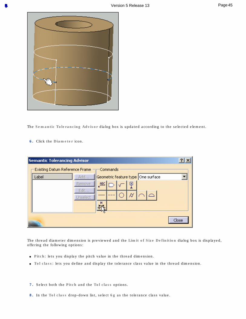
The Semantic Tolerancing Advisor dialog box is updated according to the selected element.
6. Click the Diameter icon.
The thread diameter dimension is previewed and the Limit of Size Definition dialog box is displayed, offering the following options:
● Pitch: lets you display the pitch value in the thread dimension.
● Tol class: lets you define and display the tolerance class value in the thread dimension.
7. Select both the Pitch and the Tol class options.
8. In the Tol class drop-down list, select 6g as the tolerance class value.
45Page Functional Tolerancing & Annotation Version 5 Release 13
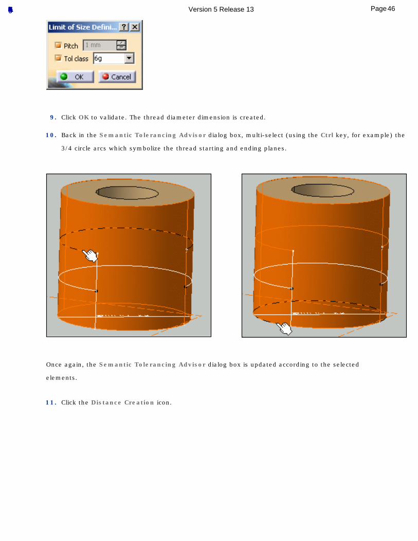
9. Click OK to validate. The thread diameter dimension is created.
10. Back in the Semantic Tolerancing Advisor dialog box, multi-select (using the Ctrl key, for example) the
3/4 circle arcs which symbolize the thread starting and ending planes.
Once again, the Semantic Tolerancing Advisor dialog box is updated according to the selected
elements.
11. Click the Distance Creation icon.
46Page Functional Tolerancing & Annotation Version 5 Release 13
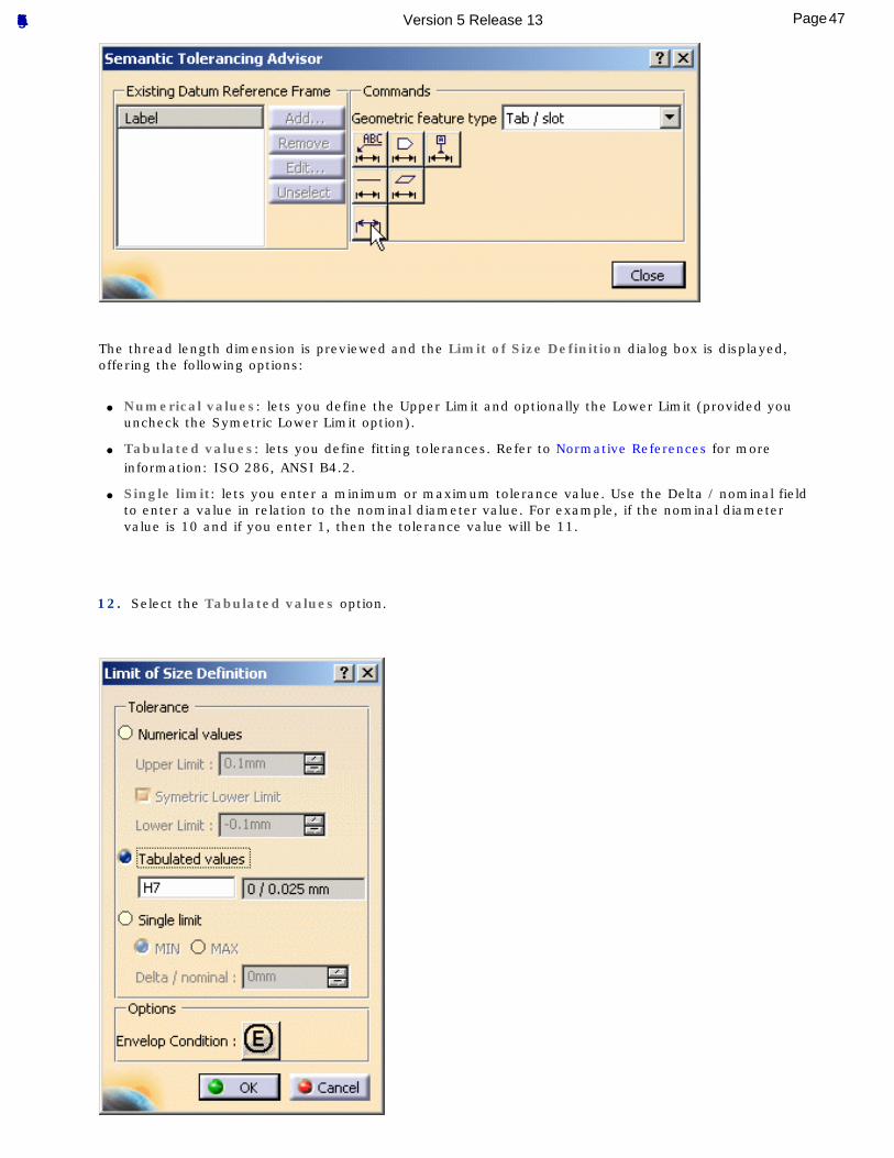
The thread length dimension is previewed and the Limit of Size Definition dialog box is displayed, offering the following options:
● Numerical values: lets you define the Upper Limit and optionally the Lower Limit (provided you uncheck the Symetric Lower Limit option).
● Tabulated values: lets you define fitting tolerances. Refer to Normative References for more information: ISO 286, ANSI B4.2.
● Single limit: lets you enter a minimum or maximum tolerance value. Use the Delta / nominal field to enter a value in relation to the nominal diameter value. For example, if the nominal diameter value is 10 and if you enter 1, then the tolerance value will be 11.
12. Select the Tabulated values option.
47Page Functional Tolerancing & Annotation Version 5 Release 13
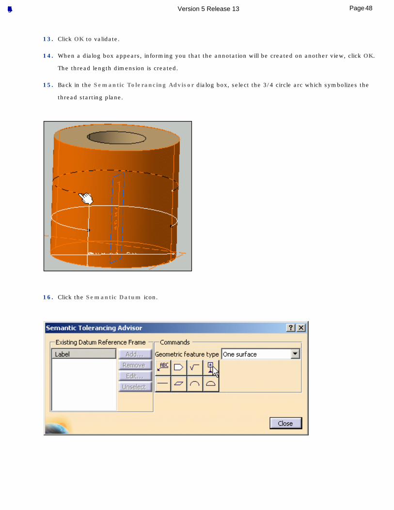
13. Click OK to validate.
14. When a dialog box appears, informing you that the annotation will be created on another view, click OK.
The thread length dimension is created.
15. Back in the Semantic Tolerancing Advisor dialog box, select the 3/4 circle arc which symbolizes the
thread starting plane.
16. Click the Semantic Datum icon.
48Page Functional Tolerancing & Annotation Version 5 Release 13
The Datum Definition dialog box is displayed.
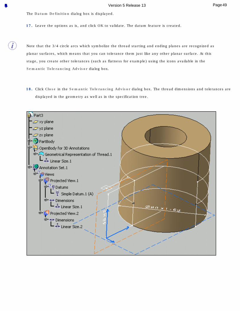
17. Leave the options as is, and click OK to validate. The datum feature is created.
Note that the 3/4 circle arcs which symbolize the thread starting and ending planes are recognized as
planar surfaces, which means that you can tolerance them just like any other planar surface. At this
stage, you create other tolerances (such as flatness for example) using the icons available in the
Semantic Tolerancing Advisor dialog box.
18. Click Close in the Semantic Tolerancing Advisor dialog box. The thread dimensions and tolerances are
displayed in the geometry as well as in the specification tree.
49Page Functional Tolerancing & Annotation Version 5 Release 13
Tolerancing Body in WhiteThe tasks described in the following scenario are meant to be performed step by step.
Creating Datum and Datum TargetsCreating Dimensions and Associated Datum
Creating a Datum Reference FrameTolerancing Body in White Holes
Tolerancing Body in White Surface
50Page Functional Tolerancing & Annotation Version 5 Release 13
Creating Datum and Datum Targets
This task shows you how to create datum and datum targets on body in white surfaces.
Open the Tolerancing_Annotations_06 CATPart document.
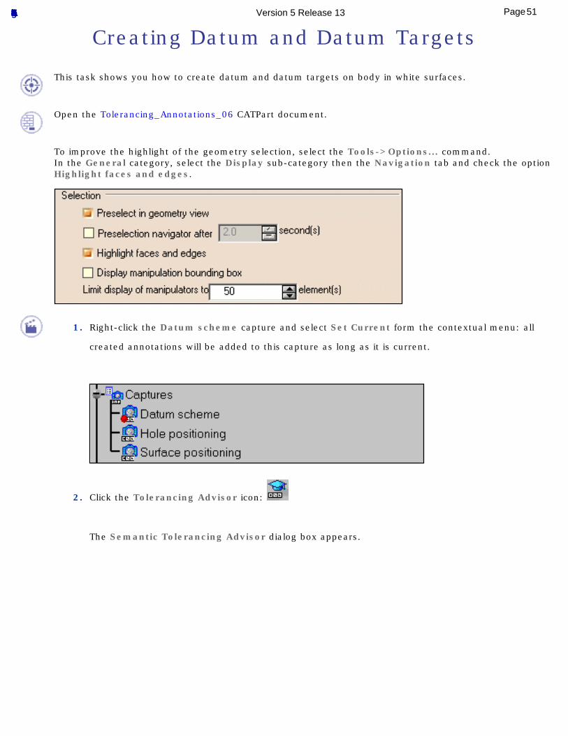
To improve the highlight of the geometry selection, select the Tools->Options... command.In the General category, select the Display sub-category then the Navigation tab and check the option Highlight faces and edges.
1. Right-click the Datum scheme capture and select Set Current form the contextual menu: all
created annotations will be added to this capture as long as it is current.
2. Click the Tolerancing Advisor icon:
The Semantic Tolerancing Advisor dialog box appears.
51Page Functional Tolerancing & Annotation Version 5 Release 13
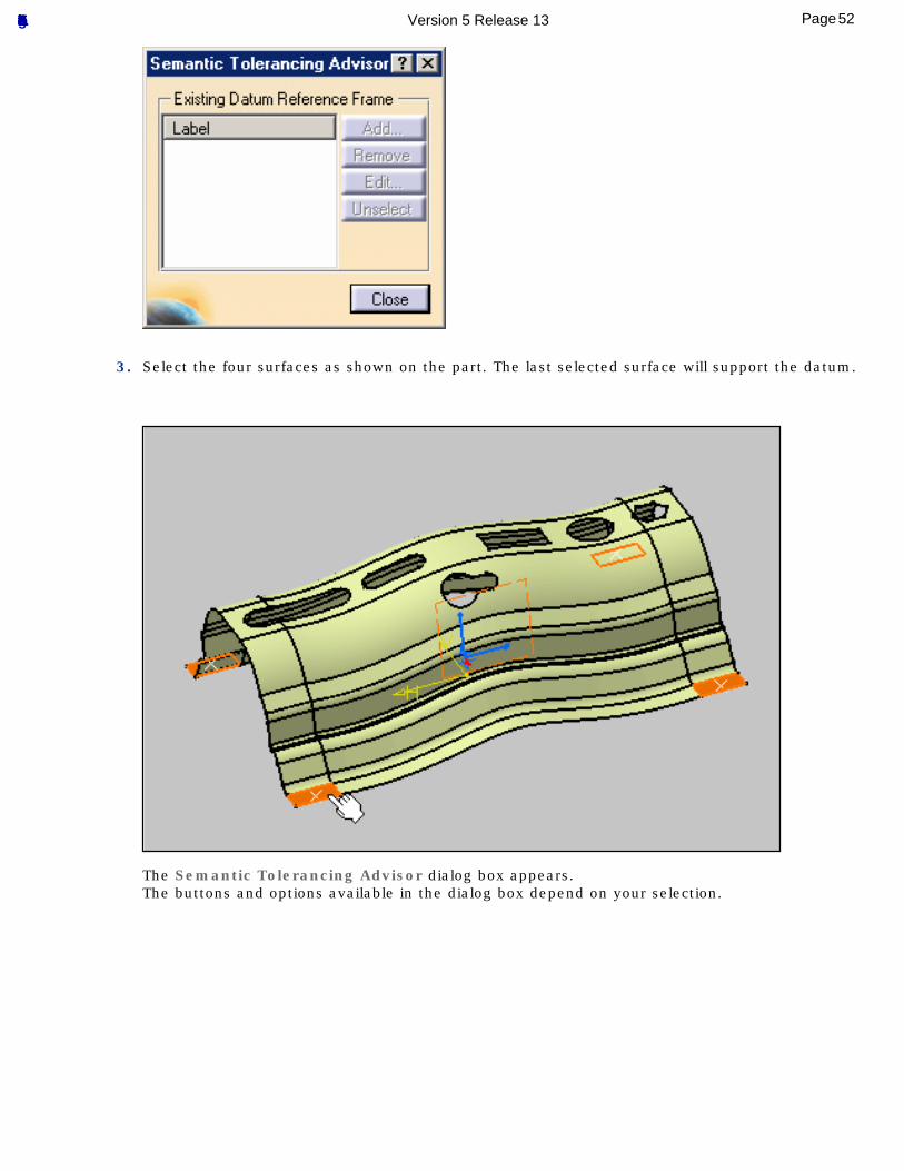
3. Select the four surfaces as shown on the part. The last selected surface will support the datum.
The Semantic Tolerancing Advisor dialog box appears.The buttons and options available in the dialog box depend on your selection.
52Page Functional Tolerancing & Annotation Version 5 Release 13
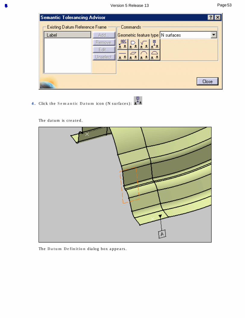
4. Click the Semantic Datum icon (N surfaces):
The datum is created.
The Datum Definition dialog box appears.
53Page Functional Tolerancing & Annotation Version 5 Release 13
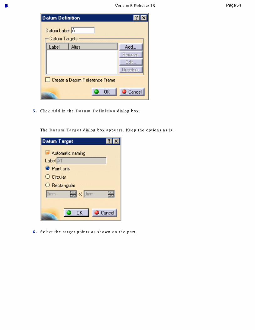
5. Click Add in the Datum Definition dialog box.
The Datum Target dialog box appears. Keep the options as is.
6. Select the target points as shown on the part.
54Page Functional Tolerancing & Annotation Version 5 Release 13
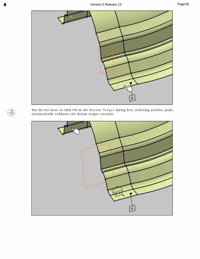
You do not have to click OK in the Datum Target dialog box, selecting another point automatically validates the datum target creation.
55Page Functional Tolerancing & Annotation Version 5 Release 13
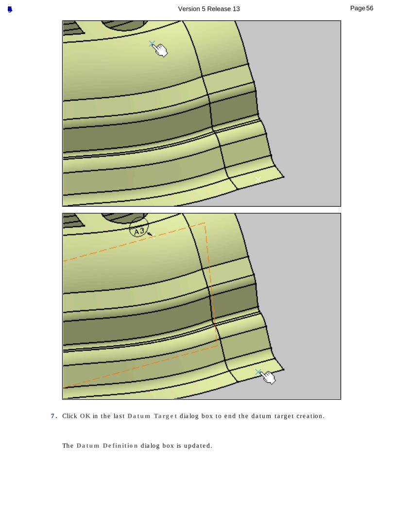
7. Click OK in the last Datum Target dialog box to end the datum target creation.
The Datum Definition dialog box is updated.
56Page Functional Tolerancing & Annotation Version 5 Release 13
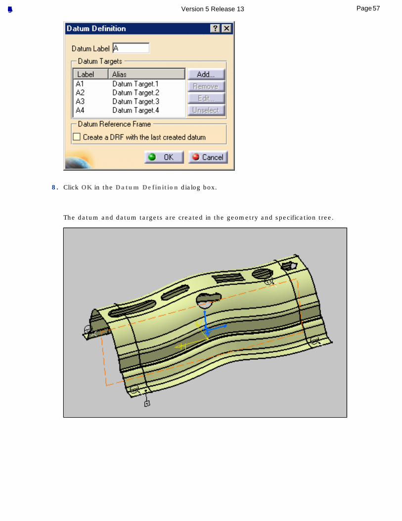
8. Click OK in the Datum Definition dialog box.
The datum and datum targets are created in the geometry and specification tree.
57Page Functional Tolerancing & Annotation Version 5 Release 13
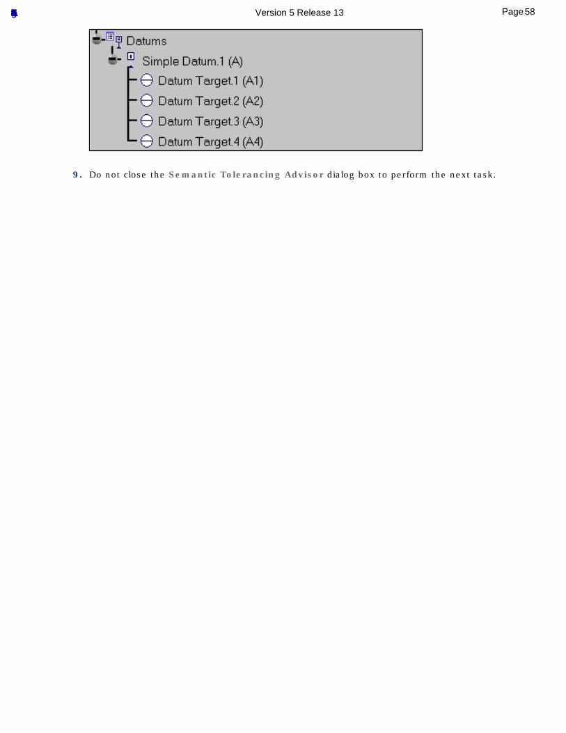
9. Do not close the Semantic Tolerancing Advisor dialog box to perform the next task.
58Page Functional Tolerancing & Annotation Version 5 Release 13
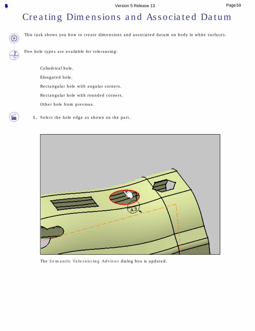
Creating Dimensions and Associated Datum
This task shows you how to create dimensions and associated datum on body in white surfaces.
Five hole types are available for tolerancing:
Cylindrical hole.
Elongated hole.
Rectangular hole with angular corners.
Rectangular hole with rounded corners.
Other hole from previous.
1. Select the hole edge as shown on the part.
The Semantic Tolerancing Advisor dialog box is updated.
59Page Functional Tolerancing & Annotation Version 5 Release 13
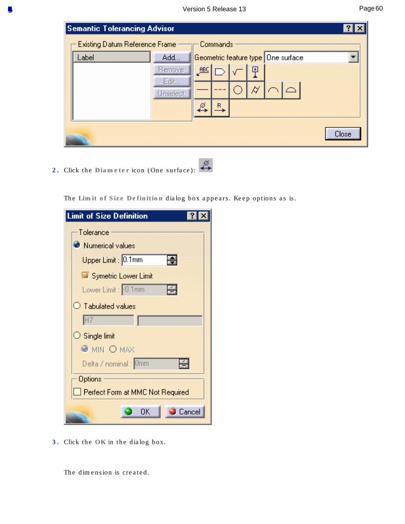
2. Click the Diameter icon (One surface):
The Limit of Size Definition dialog box appears. Keep options as is.
3. Click the OK in the dialog box.
The dimension is created.
60Page Functional Tolerancing & Annotation Version 5 Release 13
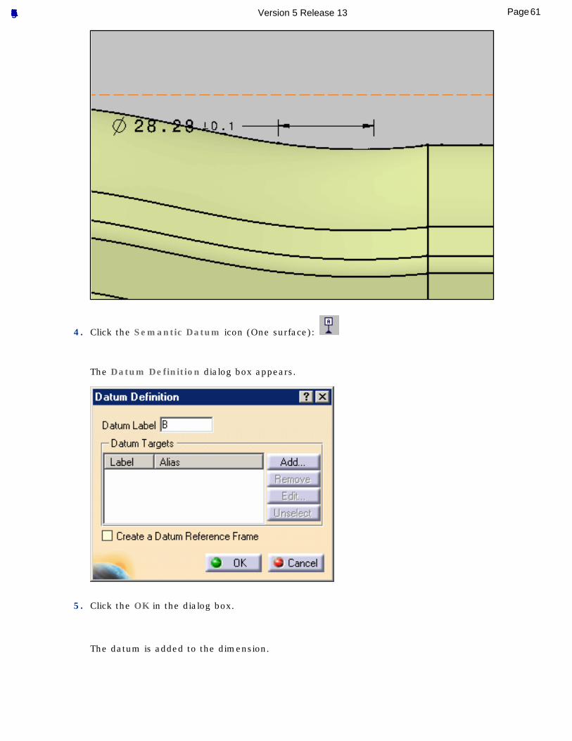
4. Click the Semantic Datum icon (One surface):
The Datum Definition dialog box appears.
5. Click the OK in the dialog box.
The datum is added to the dimension.
61Page Functional Tolerancing & Annotation Version 5 Release 13
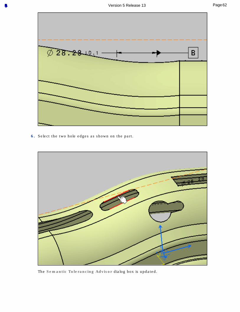
6. Select the two hole edges as shown on the part.
The Semantic Tolerancing Advisor dialog box is updated.
62Page Functional Tolerancing & Annotation Version 5 Release 13
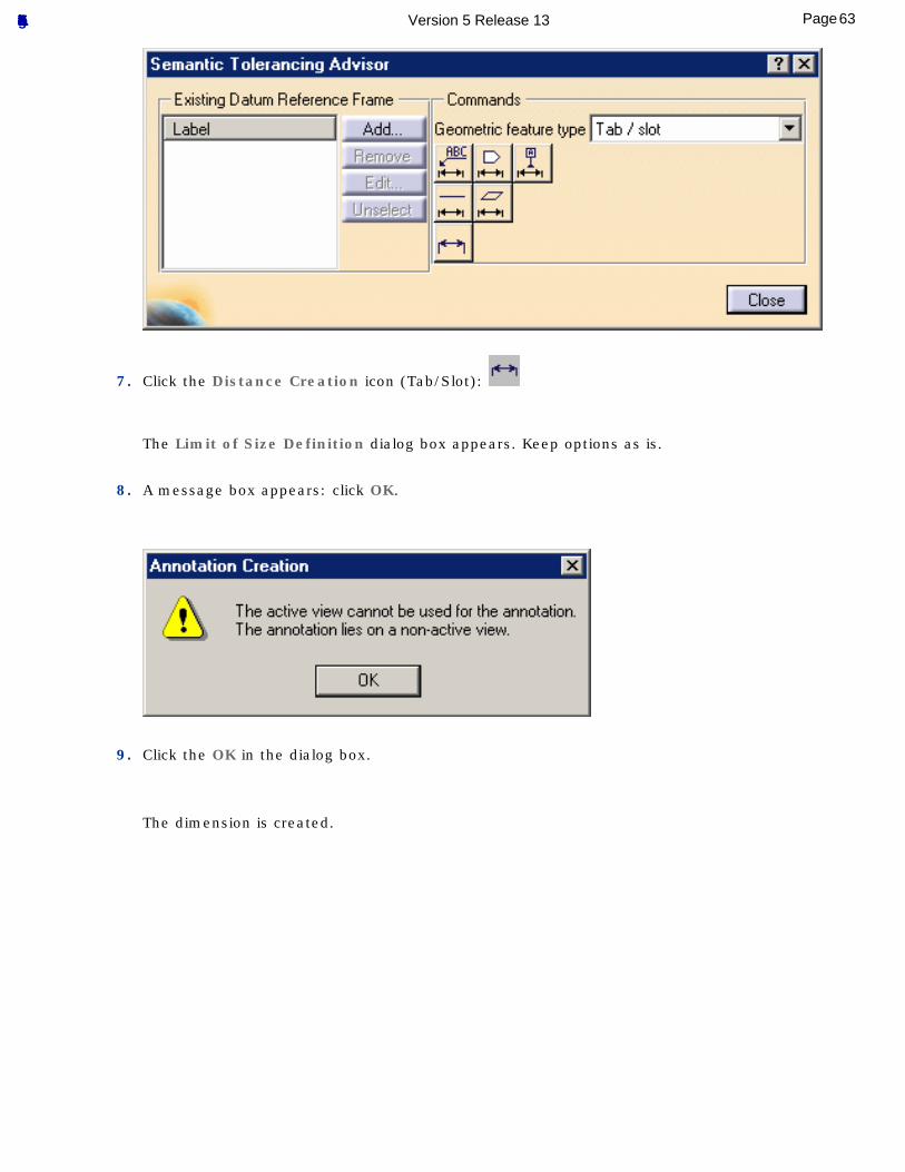
7. Click the Distance Creation icon (Tab/Slot):
The Limit of Size Definition dialog box appears. Keep options as is.
8. A message box appears: click OK.
9. Click the OK in the dialog box.
The dimension is created.
63Page Functional Tolerancing & Annotation Version 5 Release 13
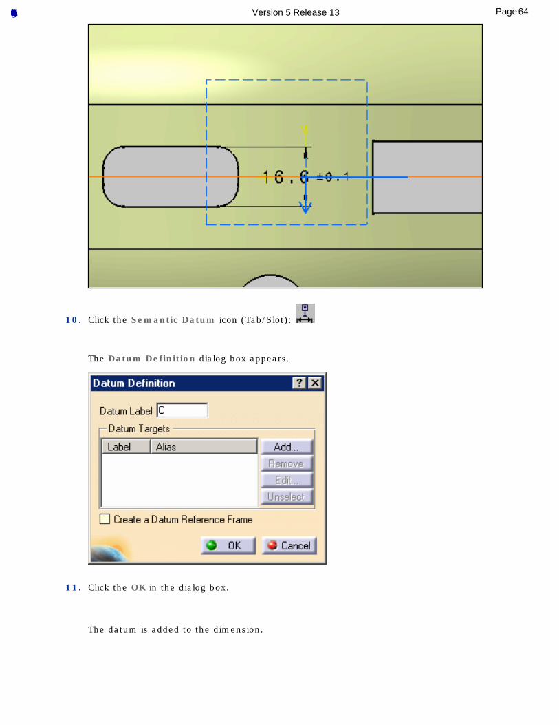
10. Click the Semantic Datum icon (Tab/Slot):
The Datum Definition dialog box appears.
11. Click the OK in the dialog box.
The datum is added to the dimension.
64Page Functional Tolerancing & Annotation Version 5 Release 13
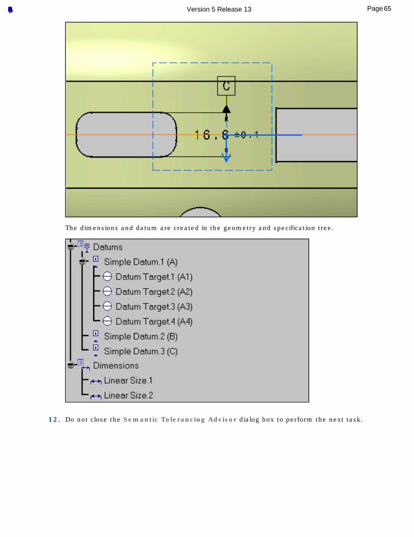
The dimensions and datum are created in the geometry and specification tree.
12. Do not close the Semantic Tolerancing Advisor dialog box to perform the next task.
65Page Functional Tolerancing & Annotation Version 5 Release 13
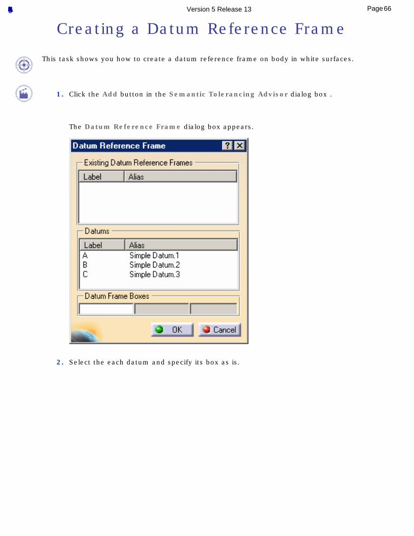
Creating a Datum Reference Frame
This task shows you how to create a datum reference frame on body in white surfaces.
1. Click the Add button in the Semantic Tolerancing Advisor dialog box .
The Datum Reference Frame dialog box appears.
2. Select the each datum and specify its box as is.
66Page Functional Tolerancing & Annotation Version 5 Release 13
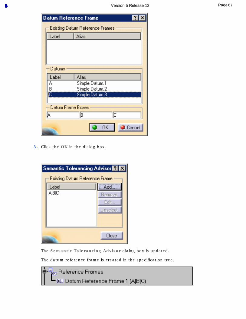
3. Click the OK in the dialog box.
The Semantic Tolerancing Advisor dialog box is updated.
The datum reference frame is created in the specification tree.
67Page Functional Tolerancing & Annotation Version 5 Release 13
4. Do not close the Semantic Tolerancing Advisor dialog box to perform the next task.
68Page Functional Tolerancing & Annotation Version 5 Release 13

Tolerancing Body in White Holes
This task shows you how to create geometrical tolerances on body in white holes.
1. Right-click the Datum scheme capture and select Unset Current form the contextual menu,
right-click the Hole positioning capture and select Set Current form the contextual menu.
2. Select the datum reference frame in the Semantic Tolerancing Advisor dialog box.
3. Select the whole hole edges as shown on the part.
69Page Functional Tolerancing & Annotation Version 5 Release 13

The Semantic Tolerancing Advisor dialog box is updated. Note the geometric feature type: Elongated Pin/Hole.
4. Click the Position with DRF Specification icon:
70Page Functional Tolerancing & Annotation Version 5 Release 13
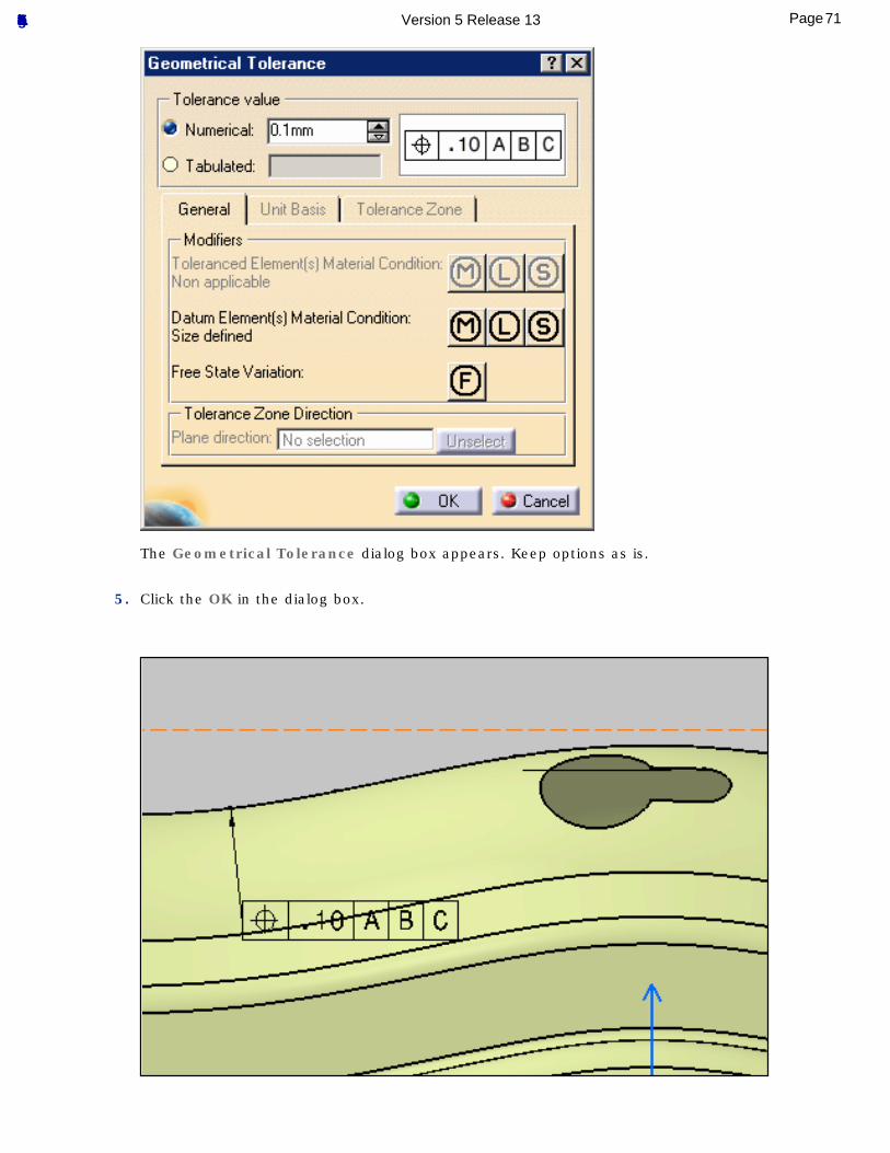
The Geometrical Tolerance dialog box appears. Keep options as is.
5. Click the OK in the dialog box.
71Page Functional Tolerancing & Annotation Version 5 Release 13
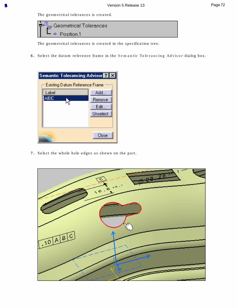
The geometrical tolerances is created.
The geometrical tolerances is created in the specification tree.
6. Select the datum reference frame in the Semantic Tolerancing Advisor dialog box.
7. Select the whole hole edges as shown on the part.
72Page Functional Tolerancing & Annotation Version 5 Release 13
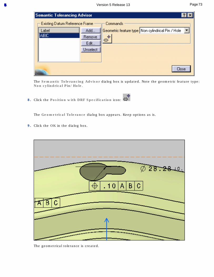
The Semantic Tolerancing Advisor dialog box is updated. Note the geometric feature type: Non cylindrical Pin/Hole.
8. Click the Position with DRF Specification icon:
The Geometrical Tolerance dialog box appears. Keep options as is.
9. Click the OK in the dialog box.
The geometrical tolerance is created.
73Page Functional Tolerancing & Annotation Version 5 Release 13
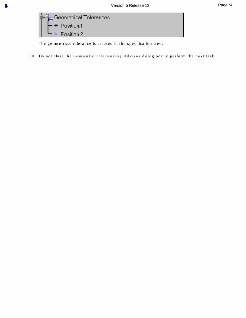
The geometrical tolerance is created in the specification tree.
10. Do not close the Semantic Tolerancing Advisor dialog box to perform the next task.
74Page Functional Tolerancing & Annotation Version 5 Release 13
Tolerancing Body in White Surface
This task shows you how to create geometrical tolerances on a body in white surface.
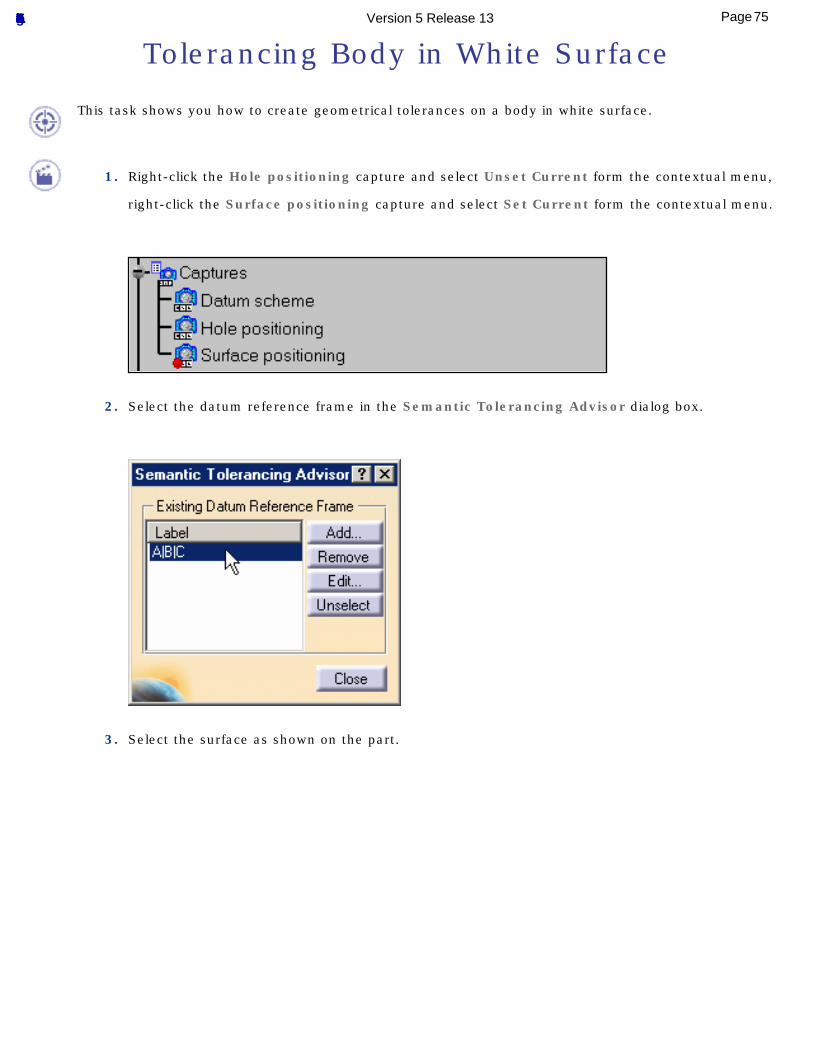
1. Right-click the Hole positioning capture and select Unset Current form the contextual menu,
right-click the Surface positioning capture and select Set Current form the contextual menu.
2. Select the datum reference frame in the Semantic Tolerancing Advisor dialog box.
3. Select the surface as shown on the part.
75Page Functional Tolerancing & Annotation Version 5 Release 13
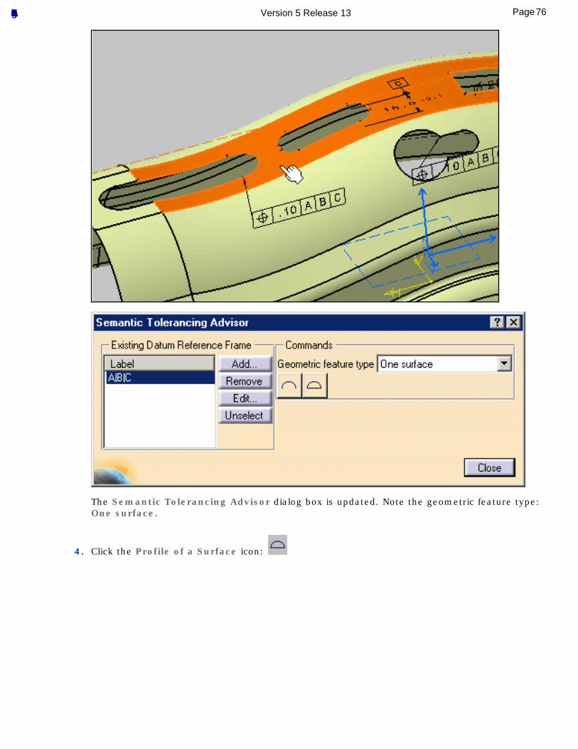
The Semantic Tolerancing Advisor dialog box is updated. Note the geometric feature type: One surface.
4. Click the Profile of a Surface icon:
76Page Functional Tolerancing & Annotation Version 5 Release 13
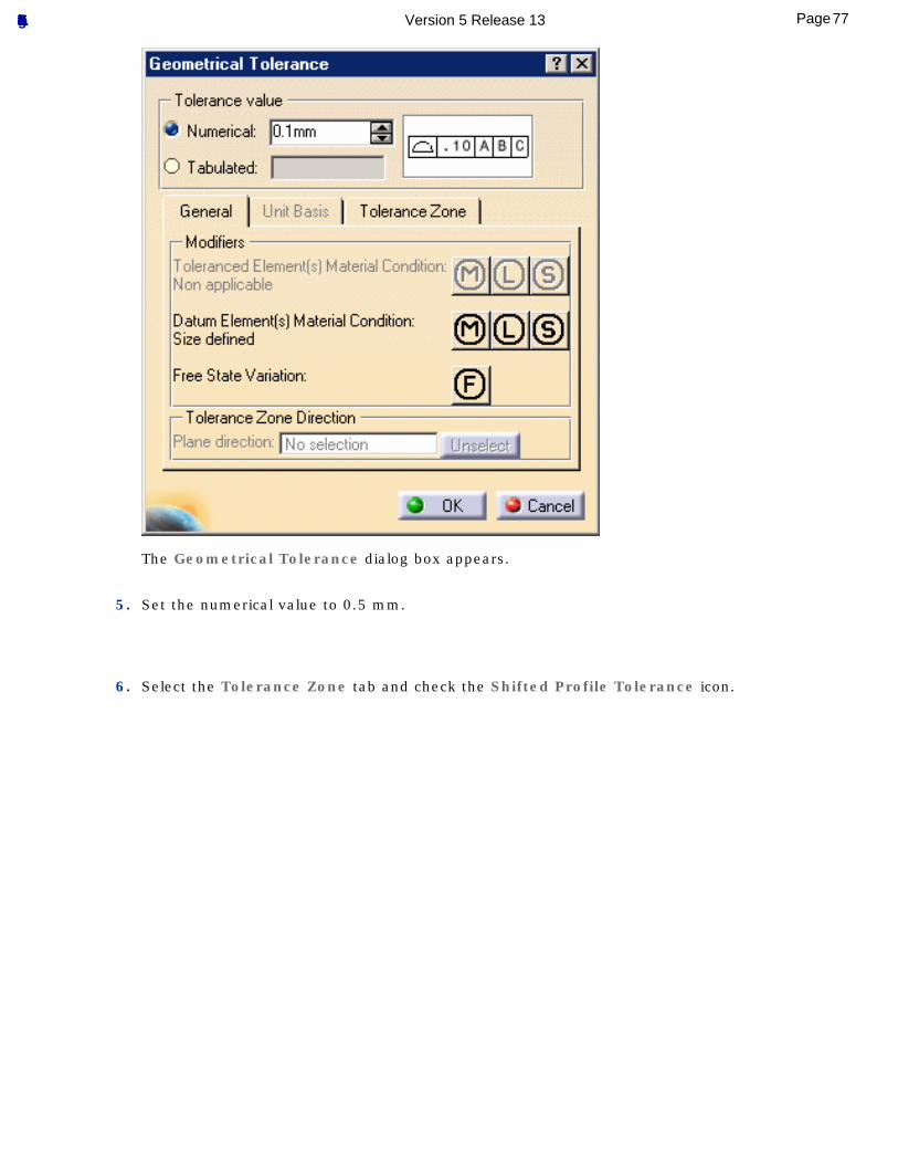
The Geometrical Tolerance dialog box appears.
5. Set the numerical value to 0.5 mm.
6. Select the Tolerance Zone tab and check the Shifted Profile Tolerance icon.
77Page Functional Tolerancing & Annotation Version 5 Release 13
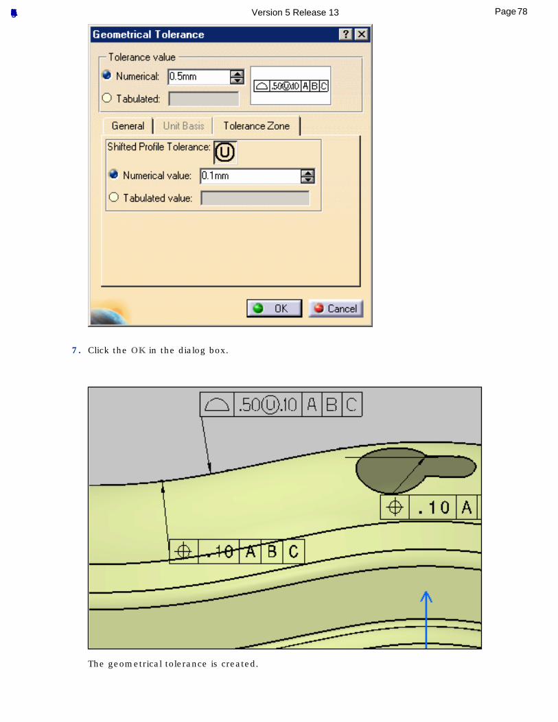
7. Click the OK in the dialog box.
The geometrical tolerance is created.
78Page Functional Tolerancing & Annotation Version 5 Release 13
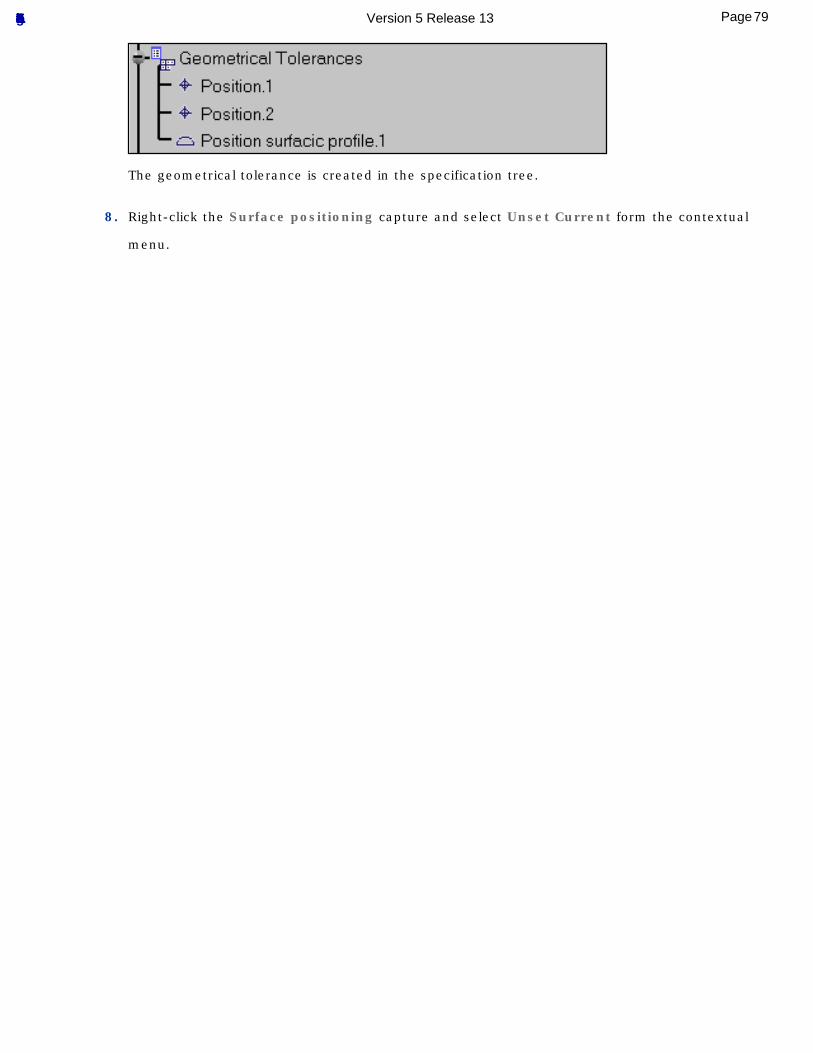
The geometrical tolerance is created in the specification tree.
8. Right-click the Surface positioning capture and select Unset Current form the contextual
menu.
79Page Functional Tolerancing & Annotation Version 5 Release 13
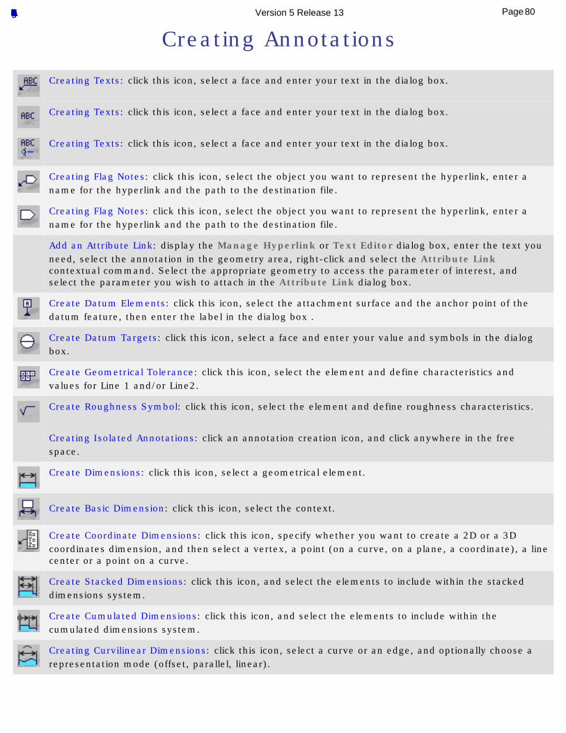
Creating Annotations
Creating Texts: click this icon, select a face and enter your text in the dialog box.
Creating Texts: click this icon, select a face and enter your text in the dialog box.
Creating Texts: click this icon, select a face and enter your text in the dialog box.
Creating Flag Notes: click this icon, select the object you want to represent the hyperlink, enter a name for the hyperlink and the path to the destination file.
Creating Flag Notes: click this icon, select the object you want to represent the hyperlink, enter a name for the hyperlink and the path to the destination file.
Add an Attribute Link: display the Manage Hyperlink or Text Editor dialog box, enter the text you need, select the annotation in the geometry area, right-click and select the Attribute Link contextual command. Select the appropriate geometry to access the parameter of interest, and select the parameter you wish to attach in the Attribute Link dialog box.
Create Datum Elements: click this icon, select the attachment surface and the anchor point of the datum feature, then enter the label in the dialog box .
Create Datum Targets: click this icon, select a face and enter your value and symbols in the dialog box.
Create Geometrical Tolerance: click this icon, select the element and define characteristics and values for Line 1 and/or Line2.
Create Roughness Symbol: click this icon, select the element and define roughness characteristics.
Creating Isolated Annotations: click an annotation creation icon, and click anywhere in the free space.
Create Dimensions: click this icon, select a geometrical element.
Create Basic Dimension: click this icon, select the context.
Create Coordinate Dimensions: click this icon, specify whether you want to create a 2D or a 3D coordinates dimension, and then select a vertex, a point (on a curve, on a plane, a coordinate), a line center or a point on a curve.
Create Stacked Dimensions: click this icon, and select the elements to include within the stacked dimensions system.
Create Cumulated Dimensions: click this icon, and select the elements to include within the cumulated dimensions system.
Creating Curvilinear Dimensions: click this icon, select a curve or an edge, and optionally choose a representation mode (offset, parallel, linear).
80Page Functional Tolerancing & Annotation Version 5 Release 13
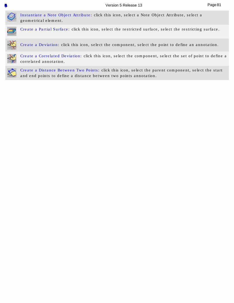
Instantiate a Note Object Attribute: click this icon, select a Note Object Attribute, select a geometrical element.
Create a Partial Surface: click this icon, select the restricted surface, select the restricting surface.
Create a Deviation: click this icon, select the component, select the point to define an annotation.
Create a Correlated Deviation: click this icon, select the component, select the set of point to define a correlated annotation.
Create a Distance Between Two Points: click this icon, select the parent component, select the start and end points to define a distance between two points annotation.
81Page Functional Tolerancing & Annotation Version 5 Release 13
Creating Texts
This task shows you how to create an annotation text.
Three kinds of text may be created:● Text with Leader
● Text
● Text parallel to screen
A text is assigned an unlimited width text frame. You can set graphic properties (anchor point, text size and justification) either before or after you create the free text.See Setting Basic Graphical Properties.You can change any text to another kind at any time.
Open the Tolerancing_Annotations_04 CATPart document.
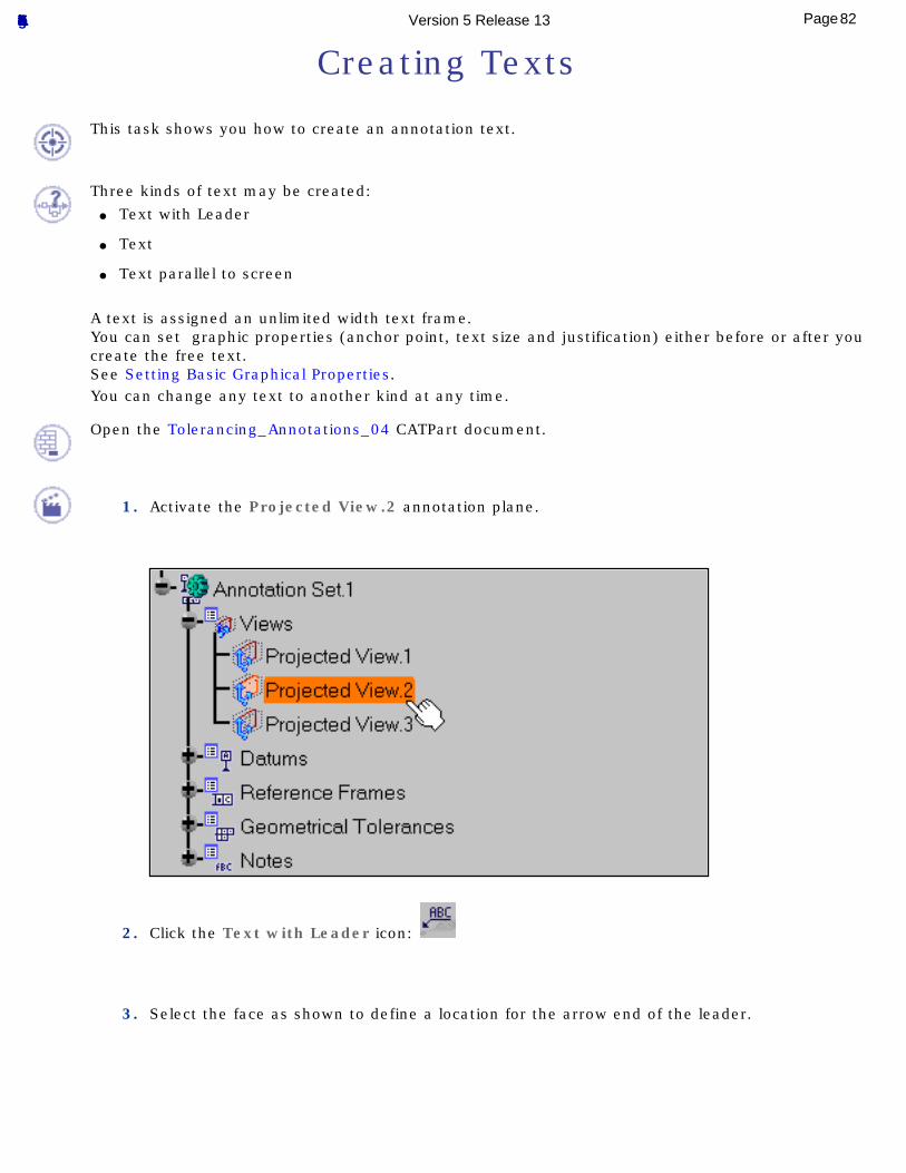
1. Activate the Projected View.2 annotation plane.
2. Click the Text with Leader icon:
3. Select the face as shown to define a location for the arrow end of the leader.
82Page Functional Tolerancing & Annotation Version 5 Release 13
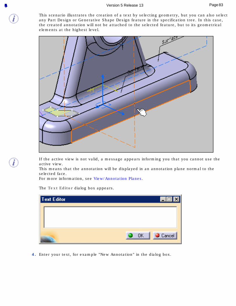
This scenario illustrates the creation of a text by selecting geometry, but you can also select any Part Design or Generative Shape Design feature in the specification tree. In this case, the created annotation will not be attached to the selected feature, but to its geometrical elements at the highest level.
If the active view is not valid, a message appears informing you that you cannot use the active view.This means that the annotation will be displayed in an annotation plane normal to the selected face.For more information, see View/Annotation Planes.
The Text Editor dialog box appears.
4. Enter your text, for example "New Annotation" in the dialog box.
83Page Functional Tolerancing & Annotation Version 5 Release 13
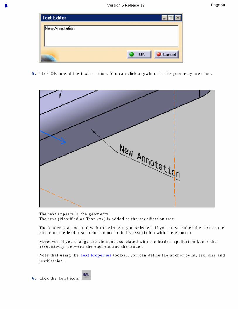
5. Click OK to end the text creation. You can click anywhere in the geometry area too.
The text appears in the geometry. The text (identified as Text.xxx) is added to the specification tree.
The leader is associated with the element you selected. If you move either the text or the element, the leader stretches to maintain its association with the element.
Moreover, if you change the element associated with the leader, application keeps the associativity between the element and the leader.
Note that using the Text Properties toolbar, you can define the anchor point, text size and justification.
6. Click the Text icon:
84Page Functional Tolerancing & Annotation Version 5 Release 13
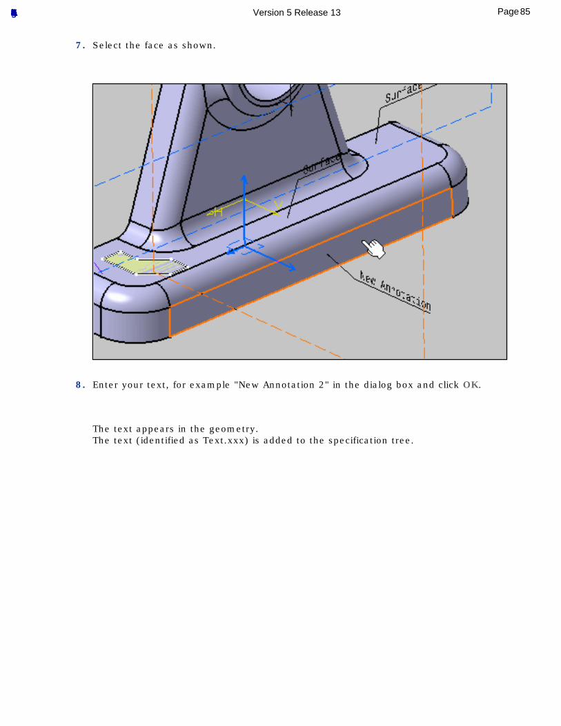
7. Select the face as shown.
8. Enter your text, for example "New Annotation 2" in the dialog box and click OK.
The text appears in the geometry. The text (identified as Text.xxx) is added to the specification tree.
85Page Functional Tolerancing & Annotation Version 5 Release 13
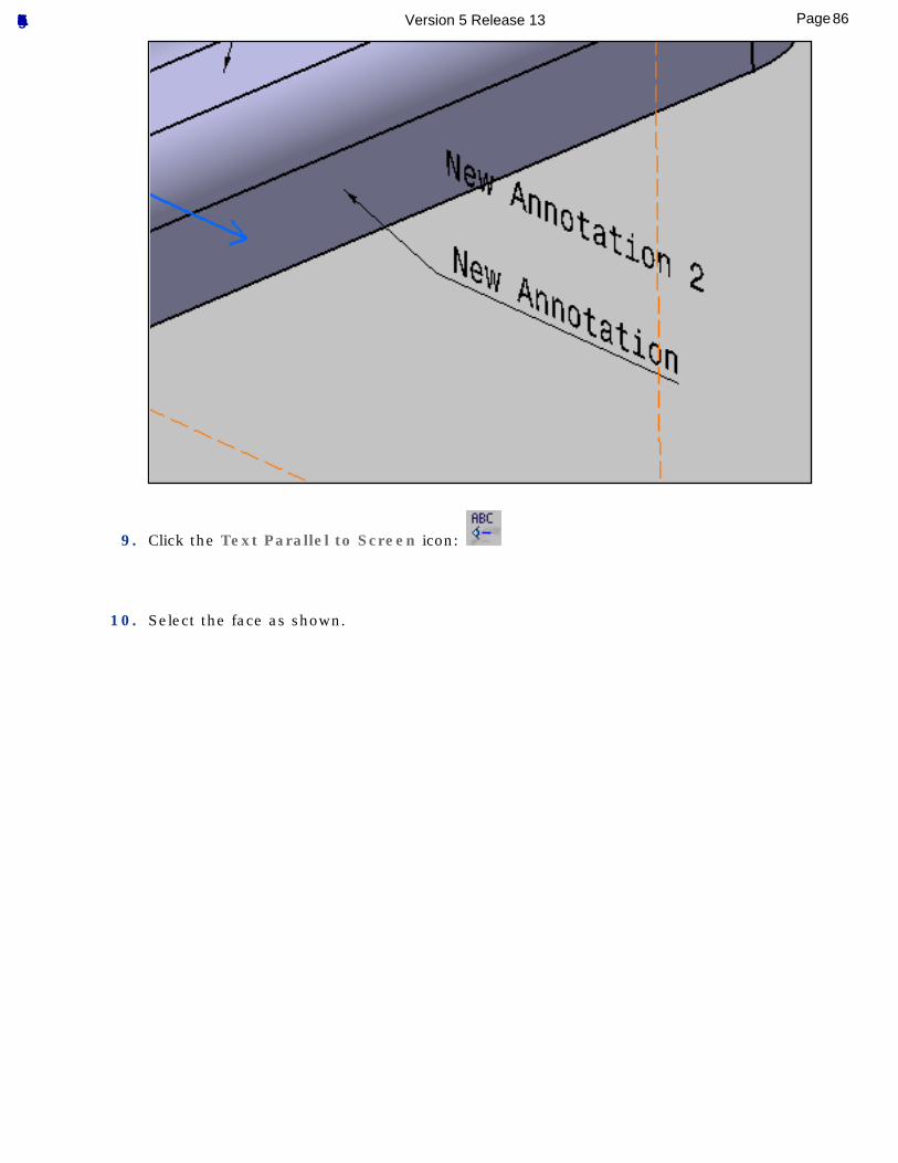
9. Click the Text Parallel to Screen icon:
10. Select the face as shown.
86Page Functional Tolerancing & Annotation Version 5 Release 13
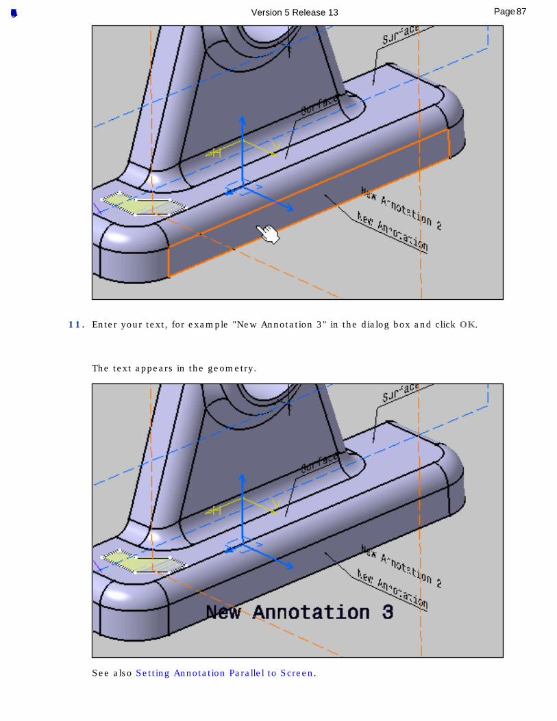
11. Enter your text, for example "New Annotation 3" in the dialog box and click OK.
The text appears in the geometry.
See also Setting Annotation Parallel to Screen.
87Page Functional Tolerancing & Annotation Version 5 Release 13
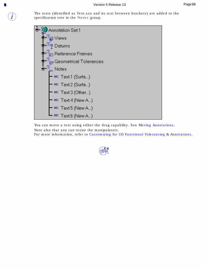
The texts (identified as Text.xxx and its text between brackets) are added to the specification tree in the Notes group.
You can move a text using either the drag capability. See Moving Annotations.Note also that you can resize the manipulators. For more information, refer to Customizing for 3D Functional Tolerancing & Annotations.
88Page Functional Tolerancing & Annotation Version 5 Release 13
Creating Flag Notes
This task shows you how to create an annotation flag note.
A flag note allows you to add links to your document and then use them to jump to a variety of locations, for example to a marketing presentation, a text document or a HTML page on the intranet.You can add links to models, products and parts as well as to any constituent elements.
Two kinds of flag note may be created:● Flag note with Leader
● Flag note
A flag note is assigned an unlimited width text frame. You can set graphic properties (anchor point, text size and justification) either before or after you create the free text.See Setting Basic Graphical Properties.You can change any flag note to another kind at any time.You can specify a hidden text to the flag note.
Open the Tolerancing_Annotations_04 CATPart document.
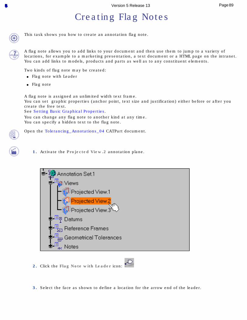
1. Activate the Projected View.2 annotation plane.
2. Click the Flag Note with Leader icon:
3. Select the face as shown to define a location for the arrow end of the leader.
89Page Functional Tolerancing & Annotation Version 5 Release 13
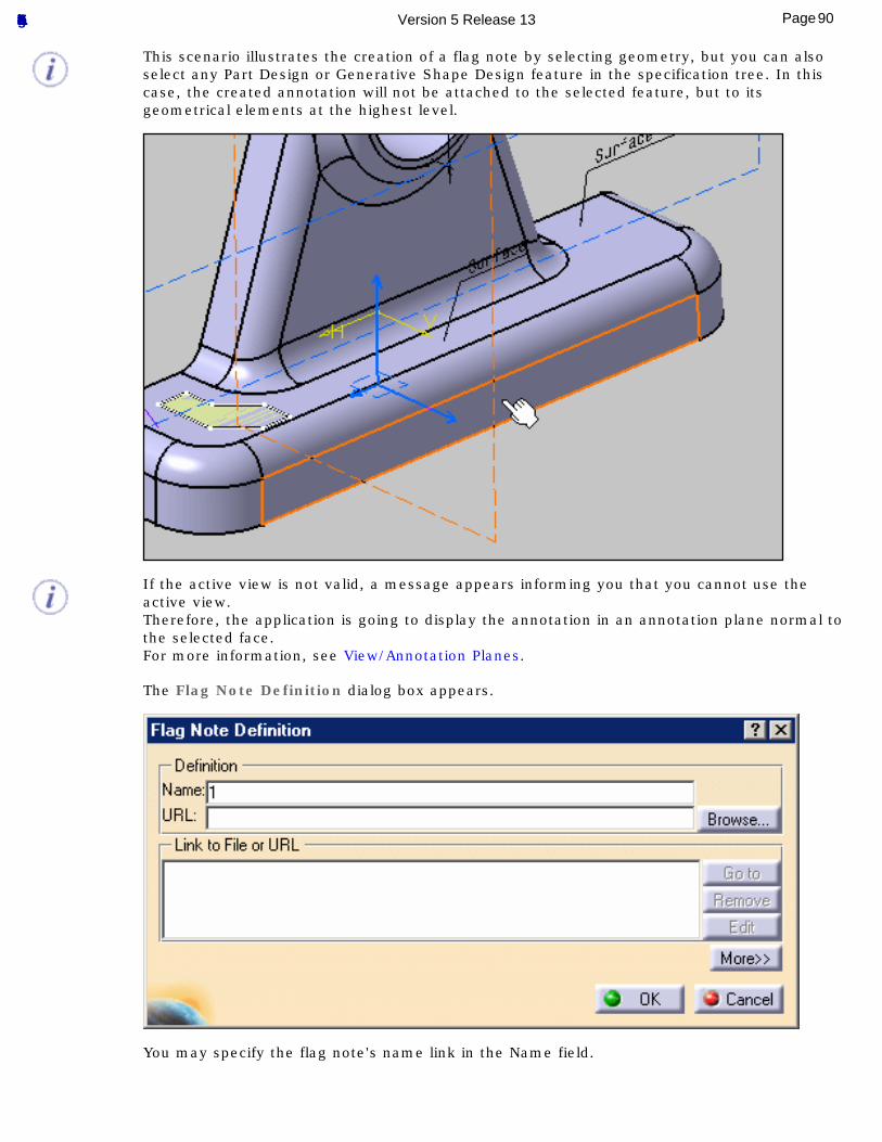
This scenario illustrates the creation of a flag note by selecting geometry, but you can also select any Part Design or Generative Shape Design feature in the specification tree. In this case, the created annotation will not be attached to the selected feature, but to its geometrical elements at the highest level.
If the active view is not valid, a message appears informing you that you cannot use the active view.Therefore, the application is going to display the annotation in an annotation plane normal to the selected face.For more information, see View/Annotation Planes.
The Flag Note Definition dialog box appears.
You may specify the flag note's name link in the Name field.
90Page Functional Tolerancing & Annotation Version 5 Release 13
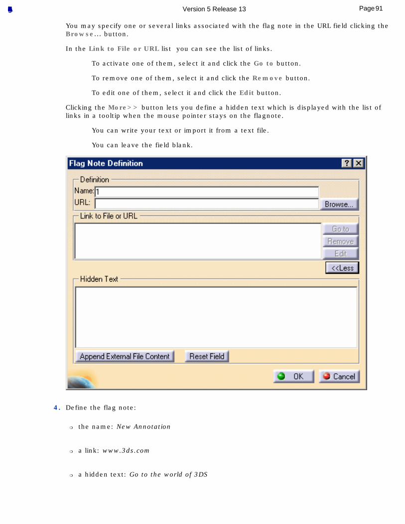
You may specify one or several links associated with the flag note in the URL field clicking the Browse... button.
In the Link to File or URL list you can see the list of links.
To activate one of them, select it and click the Go to button.
To remove one of them, select it and click the Remove button.
To edit one of them, select it and click the Edit button.
Clicking the More>> button lets you define a hidden text which is displayed with the list of links in a tooltip when the mouse pointer stays on the flagnote.
You can write your text or import it from a text file.
You can leave the field blank.
4. Define the flag note:
❍ the name: New Annotation
❍ a link: www.3ds.com
❍ a hidden text: Go to the world of 3DS
91Page Functional Tolerancing & Annotation Version 5 Release 13
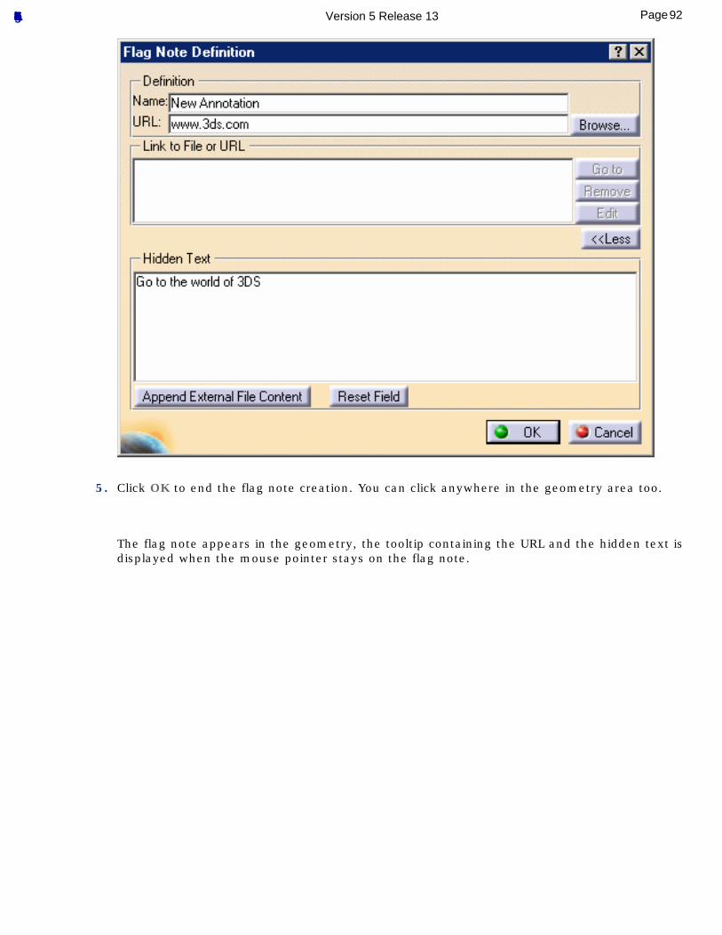
5. Click OK to end the flag note creation. You can click anywhere in the geometry area too.
The flag note appears in the geometry, the tooltip containing the URL and the hidden text is displayed when the mouse pointer stays on the flag note.
92Page Functional Tolerancing & Annotation Version 5 Release 13
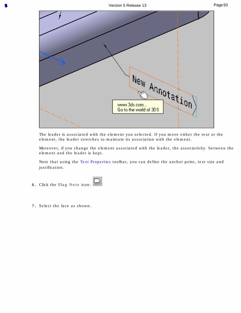
The leader is associated with the element you selected. If you move either the text or the element, the leader stretches to maintain its association with the element.
Moreover, if you change the element associated with the leader, the associativity between the element and the leader is kept.
Note that using the Text Properties toolbar, you can define the anchor point, text size and justification.
6. Click the Flag Note icon:
7. Select the face as shown.
93Page Functional Tolerancing & Annotation Version 5 Release 13
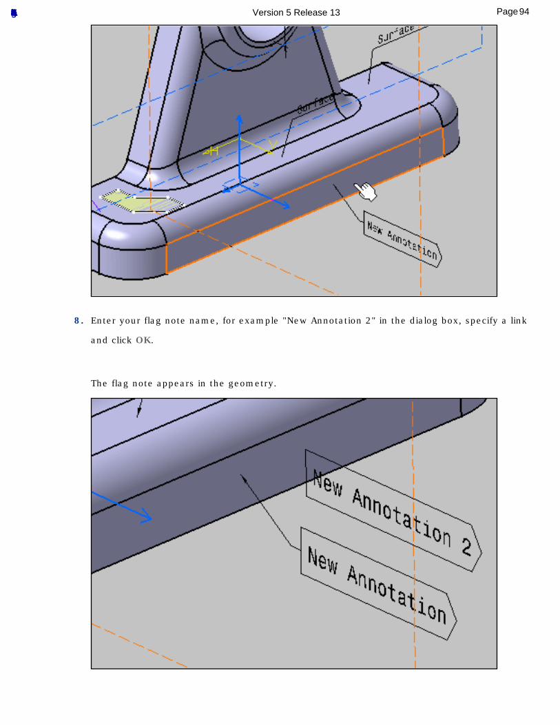
8. Enter your flag note name, for example "New Annotation 2" in the dialog box, specify a link
and click OK.
The flag note appears in the geometry.
94Page Functional Tolerancing & Annotation Version 5 Release 13
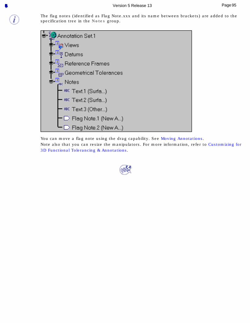
The flag notes (identified as Flag Note.xxx and its name between brackets) are added to the specification tree in the Notes group.
You can move a flag note using the drag capability. See Moving Annotations.Note also that you can resize the manipulators. For more information, refer to Customizing for 3D Functional Tolerancing & Annotations.
95Page Functional Tolerancing & Annotation Version 5 Release 13
Adding an Attribute Link
This task shows you how to add an attribute link parameter to a text while you are creating this annotation.Note that the operating mode described here is valid for Text or a Flag Note.
Open the Tolerancing_Annotations_04 CATPart document.
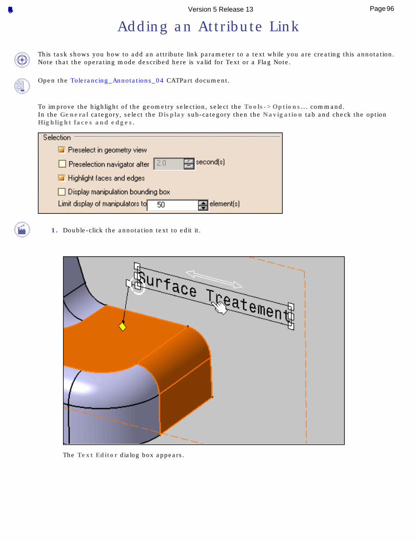
To improve the highlight of the geometry selection, select the Tools->Options... command.In the General category, select the Display sub-category then the Navigation tab and check the option Highlight faces and edges.
1. Double-click the annotation text to edit it.
The Text Editor dialog box appears.
96Page Functional Tolerancing & Annotation Version 5 Release 13
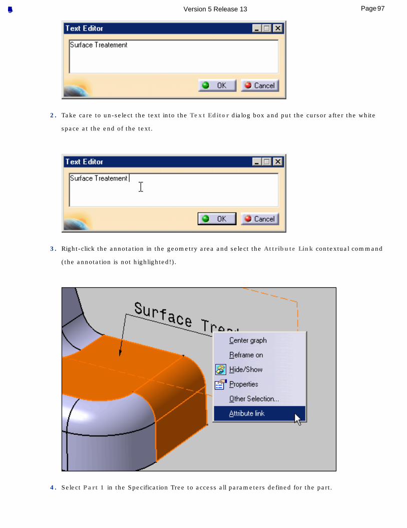
2. Take care to un-select the text into the Text Editor dialog box and put the cursor after the white
space at the end of the text.
3. Right-click the annotation in the geometry area and select the Attribute Link contextual command
(the annotation is not highlighted!).
4. Select Part 1 in the Specification Tree to access all parameters defined for the part.
97Page Functional Tolerancing & Annotation Version 5 Release 13
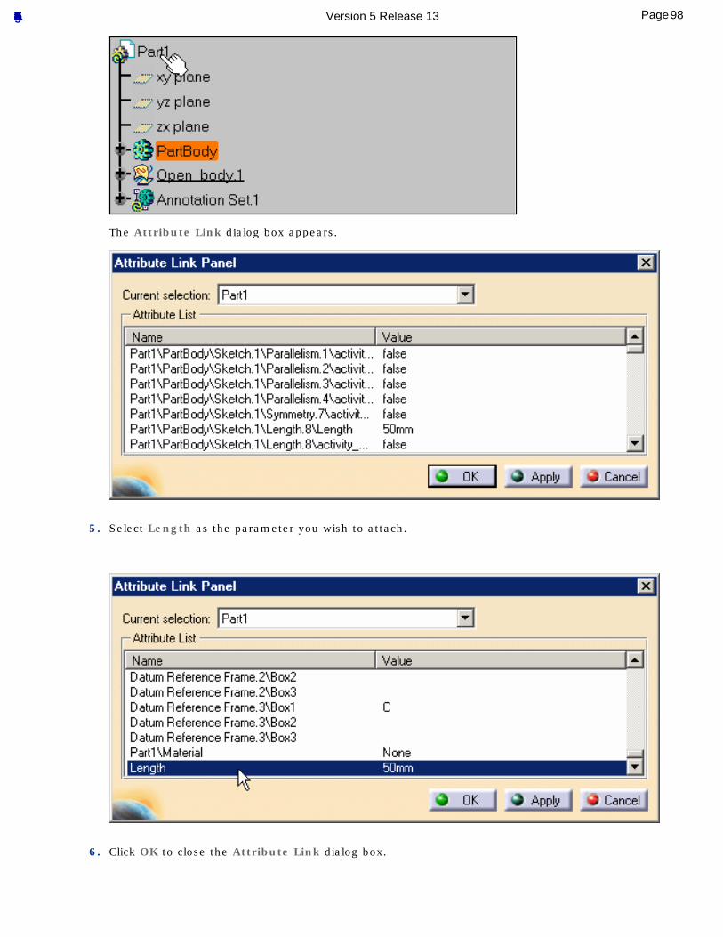
The Attribute Link dialog box appears.
5. Select Length as the parameter you wish to attach.
6. Click OK to close the Attribute Link dialog box.
98Page Functional Tolerancing & Annotation Version 5 Release 13
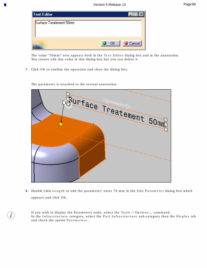
The value "50mm" now appears both in the Text Editor dialog box and in the annotation.You cannot edit this value in this dialog box but you can delete it.
7. Click OK to confirm the operation and close the dialog box.
The parameter is attached to the textual annotation.
8. Double-click Length to edit the parameter: enter 70 mm in the Edit Parameter dialog box which
appears and click OK.
If you wish to display the Parameters node, select the Tools->Options... command.In the Infrastructure category, select the Part Infrastructure sub-category then the Display tab and check the option Parameters .
99Page Functional Tolerancing & Annotation Version 5 Release 13
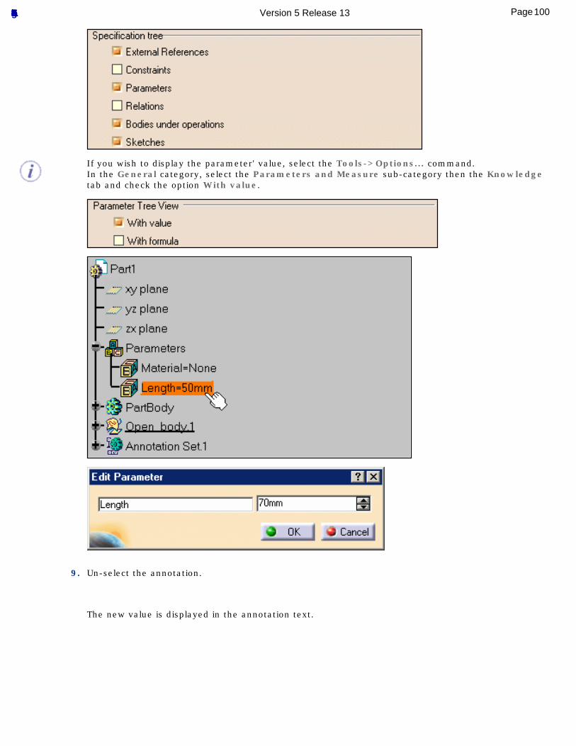
If you wish to display the parameter' value, select the Tools->Options... command.In the General category, select the Parameters and Measure sub-category then the Knowledge tab and check the option With value.
9. Un-select the annotation.
The new value is displayed in the annotation text.
100Page Functional Tolerancing & Annotation Version 5 Release 13
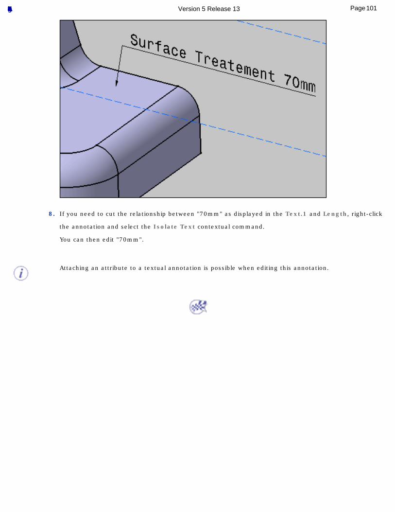
8. If you need to cut the relationship between "70mm" as displayed in the Text.1 and Length, right-click
the annotation and select the Isolate Text contextual command.
You can then edit "70mm".
Attaching an attribute to a textual annotation is possible when editing this annotation.
101Page Functional Tolerancing & Annotation Version 5 Release 13
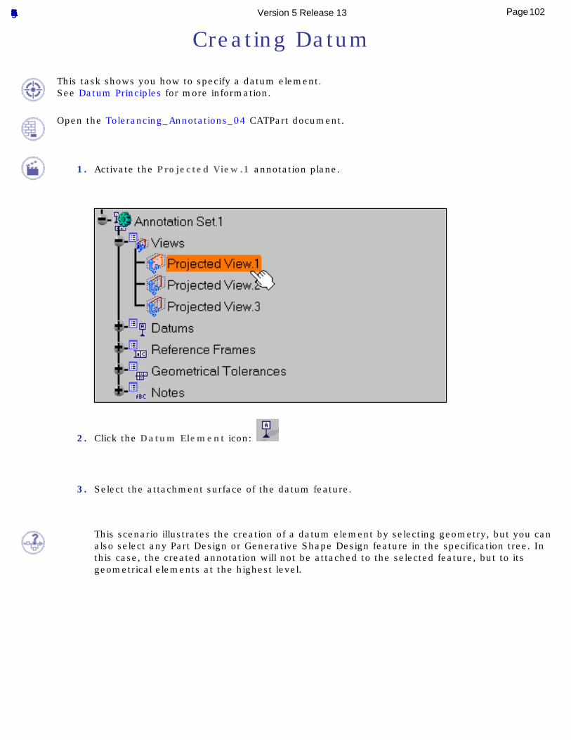
Creating Datum
This task shows you how to specify a datum element.See Datum Principles for more information.
Open the Tolerancing_Annotations_04 CATPart document.
1. Activate the Projected View.1 annotation plane.
2. Click the Datum Element icon:
3. Select the attachment surface of the datum feature.
This scenario illustrates the creation of a datum element by selecting geometry, but you can also select any Part Design or Generative Shape Design feature in the specification tree. In this case, the created annotation will not be attached to the selected feature, but to its geometrical elements at the highest level.
102Page Functional Tolerancing & Annotation Version 5 Release 13
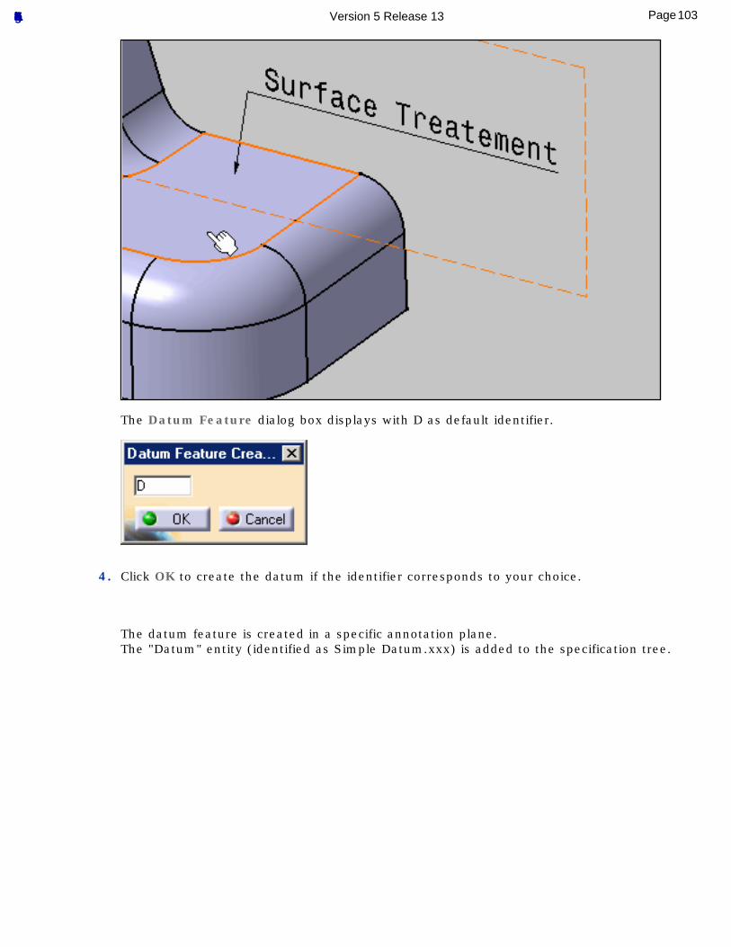
The Datum Feature dialog box displays with D as default identifier.
4. Click OK to create the datum if the identifier corresponds to your choice.
The datum feature is created in a specific annotation plane.The "Datum" entity (identified as Simple Datum.xxx) is added to the specification tree.
103Page Functional Tolerancing & Annotation Version 5 Release 13
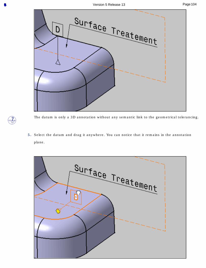
The datum is only a 3D annotation without any semantic link to the geometrical tolerancing.
5. Select the datum and drag it anywhere. You can notice that it remains in the annotation
plane.
104Page Functional Tolerancing & Annotation Version 5 Release 13
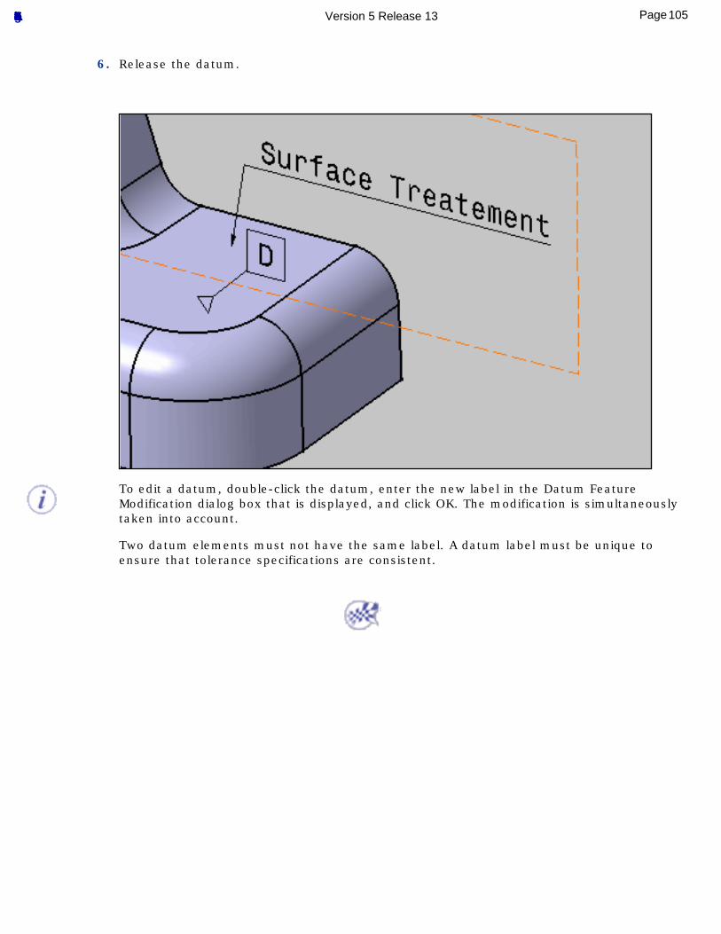
6. Release the datum.
To edit a datum, double-click the datum, enter the new label in the Datum Feature Modification dialog box that is displayed, and click OK. The modification is simultaneously taken into account.
Two datum elements must not have the same label. A datum label must be unique to ensure that tolerance specifications are consistent.
105Page Functional Tolerancing & Annotation Version 5 Release 13
Creating Datum Targets
This tasks shows you how to specify datum targets on datum elements.
Before performing the task, here are a few principles you should be familiar with:● When defining a datum on planar or cylindrical surfaces the use of datum targets is optional.
● A target element can be a point, line, circular or rectangular surface lying on the datum element:
❍ When the datum target is a point, then the circular frame is linked to a cross-placed on the surface. Framed dimensions shall define the location of the point.
❍ When the datum target is a line, then the circular frame is linked to a line placed on the surface. Framed dimensions shall define the length and the location of the line.
❍ When the datum target area is square or circular, the area dimensions are indicated in the upper compartment of the circular frame, or placed outside and connected to the appropriate compartment by a leader line (when there is no sufficient space within the compartment).
● The minimum number of targets is defined by the datum depending on whether it is used as primary, secondary or tertiary datum in a reference frame.
● For instance, if the datum feature is a cylinder, the targets may be two non-parallel lines, tangent to the cylinder and perpendicular to its centerline, in order to define "equalizing" datum ("V-type-equalizers").
● If the datum element is prismatic or complex, the use of datum targets is mandatory. In this case when selecting targets a message indicates the current step of the datum definition.
● When the datum is established from datum targets, then the letter identifying the surface is repeated on the right side of the datum indicator followed by the list of numbers identifying the targets (separated by comas).
● When there is no sufficient space within the compartment, the dimensions of the datum target area are placed outside the circular frame and connected to the appropriate compartment by a leader line terminated by a dot.
Open the Tolerancing_Annotations_04 CATPart document.
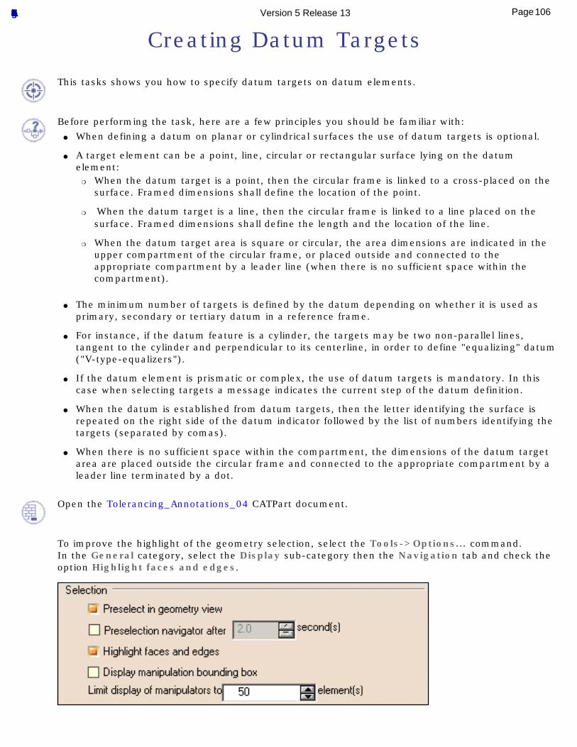
To improve the highlight of the geometry selection, select the Tools->Options... command.In the General category, select the Display sub-category then the Navigation tab and check the option Highlight faces and edges.
106Page Functional Tolerancing & Annotation Version 5 Release 13
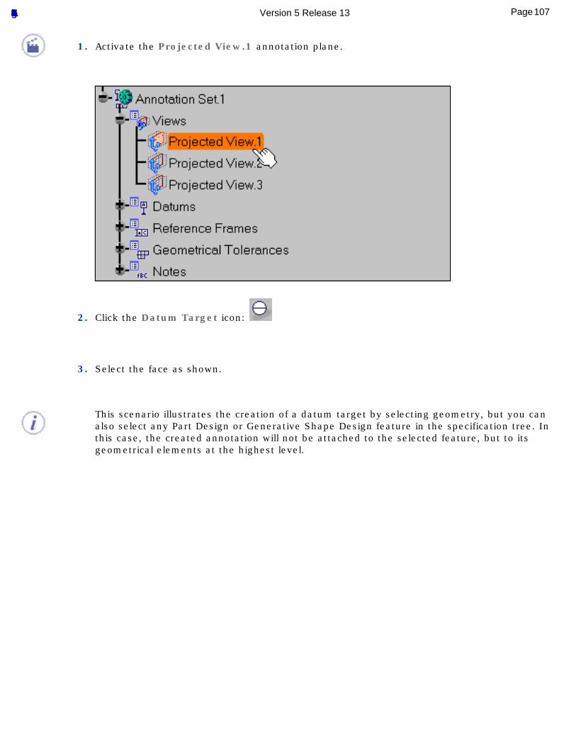
1. Activate the Projected View.1 annotation plane.
2. Click the Datum Target icon:
3. Select the face as shown.
This scenario illustrates the creation of a datum target by selecting geometry, but you can also select any Part Design or Generative Shape Design feature in the specification tree. In this case, the created annotation will not be attached to the selected feature, but to its geometrical elements at the highest level.
107Page Functional Tolerancing & Annotation Version 5 Release 13
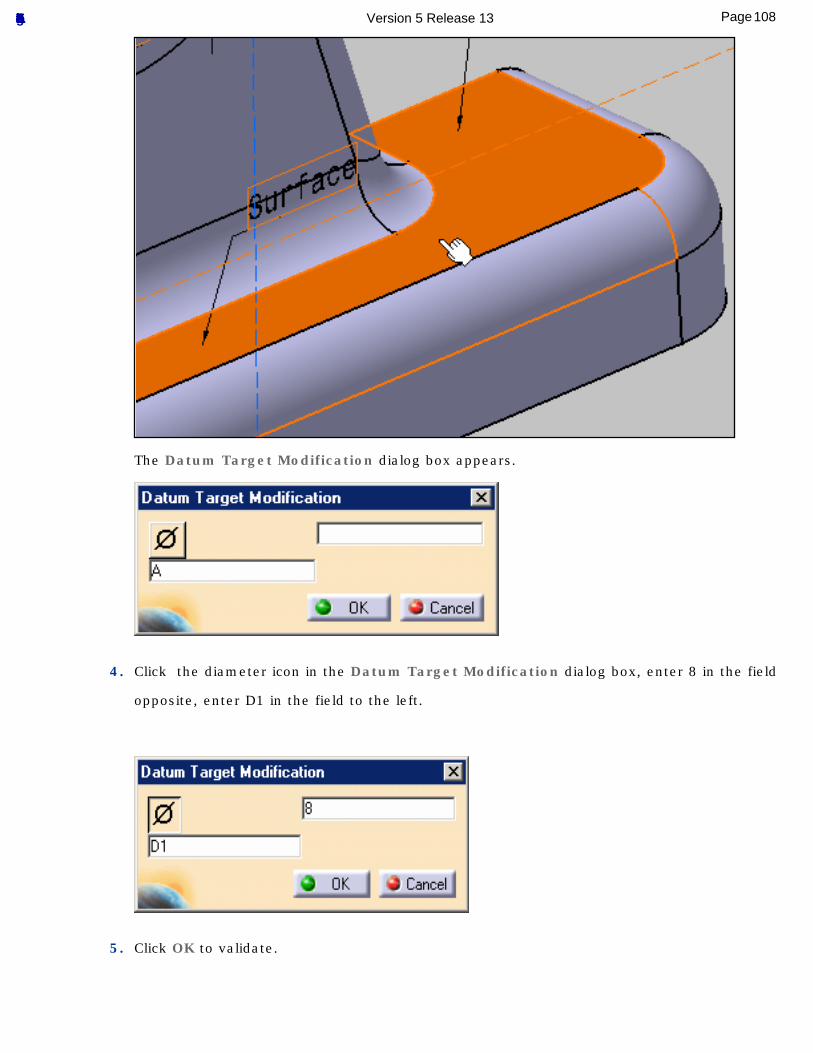
The Datum Target Modification dialog box appears.
4. Click the diameter icon in the Datum Target Modification dialog box, enter 8 in the field
opposite, enter D1 in the field to the left.
5. Click OK to validate.
108Page Functional Tolerancing & Annotation Version 5 Release 13
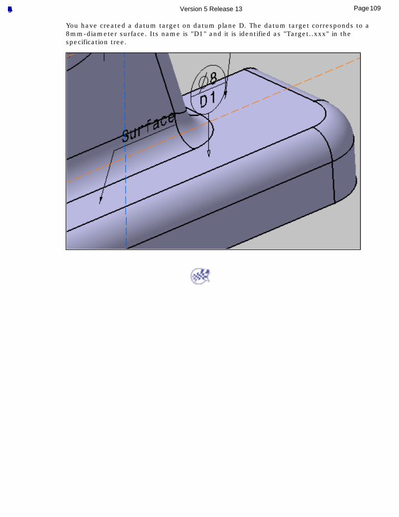
You have created a datum target on datum plane D. The datum target corresponds to a 8mm-diameter surface. Its name is "D1" and it is identified as "Target..xxx" in the specification tree.
109Page Functional Tolerancing & Annotation Version 5 Release 13
Creating Geometrical Tolerances
This task will show you how to create a geometrical tolerance annotation.
Before performing the task, here are a few principles you should be familiar with: ● Principles and Fundamental Rules for Geometrical Tolerancing
● Geometric Tolerancing
● Symbols for Geometrical Tolerances
● Symbols for Modifiers
Open the Tolerancing_Annotations_04 CATPart document.
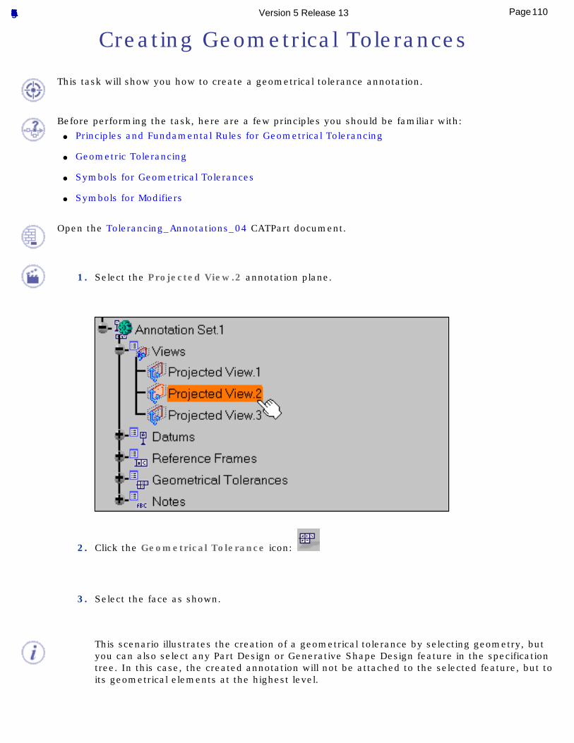
1. Select the Projected View.2 annotation plane.
2. Click the Geometrical Tolerance icon:
3. Select the face as shown.
This scenario illustrates the creation of a geometrical tolerance by selecting geometry, but you can also select any Part Design or Generative Shape Design feature in the specification tree. In this case, the created annotation will not be attached to the selected feature, but to its geometrical elements at the highest level.
110Page Functional Tolerancing & Annotation Version 5 Release 13
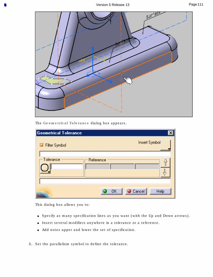
The Geometrical Tolerance dialog box appears.
This dialog box allows you to:
● Specify as many specification lines as you want (with the Up and Down arrows).
● Insert several modifiers anywhere in a tolerance or a reference.
● Add notes upper and lower the set of specification.
3. Set the parallelism symbol to define the tolerance.
111Page Functional Tolerancing & Annotation Version 5 Release 13
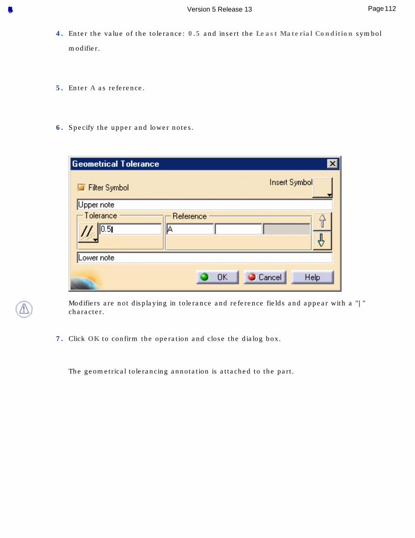
4. Enter the value of the tolerance: 0.5 and insert the Least Material Condition symbol
modifier.
5. Enter A as reference.
6. Specify the upper and lower notes.
Modifiers are not displaying in tolerance and reference fields and appear with a "|" character.
7. Click OK to confirm the operation and close the dialog box.
The geometrical tolerancing annotation is attached to the part.
112Page Functional Tolerancing & Annotation Version 5 Release 13
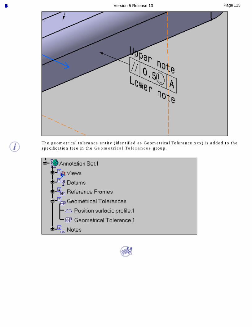
The geometrical tolerance entity (identified as Geometrical Tolerance.xxx) is added to the specification tree in the Geometrical Tolerances group.
113Page Functional Tolerancing & Annotation Version 5 Release 13
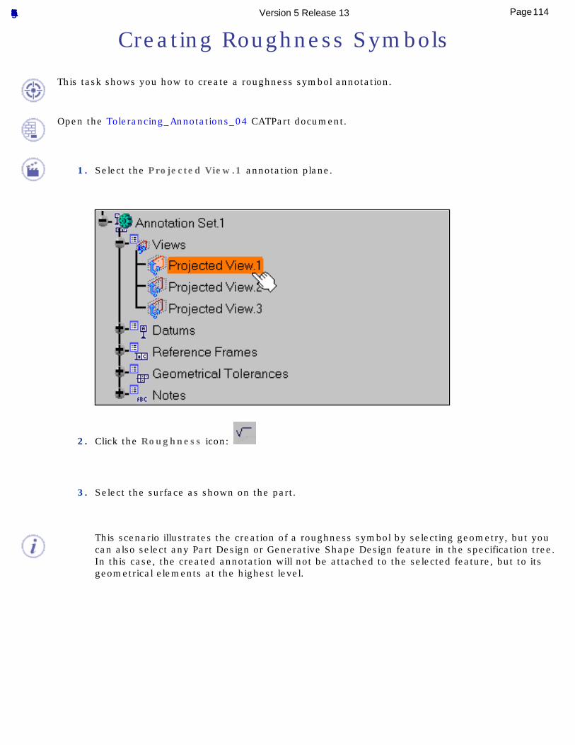
Creating Roughness Symbols
This task shows you how to create a roughness symbol annotation.
Open the Tolerancing_Annotations_04 CATPart document.
1. Select the Projected View.1 annotation plane.
2. Click the Roughness icon:
3. Select the surface as shown on the part.
This scenario illustrates the creation of a roughness symbol by selecting geometry, but you can also select any Part Design or Generative Shape Design feature in the specification tree. In this case, the created annotation will not be attached to the selected feature, but to its geometrical elements at the highest level.
114Page Functional Tolerancing & Annotation Version 5 Release 13
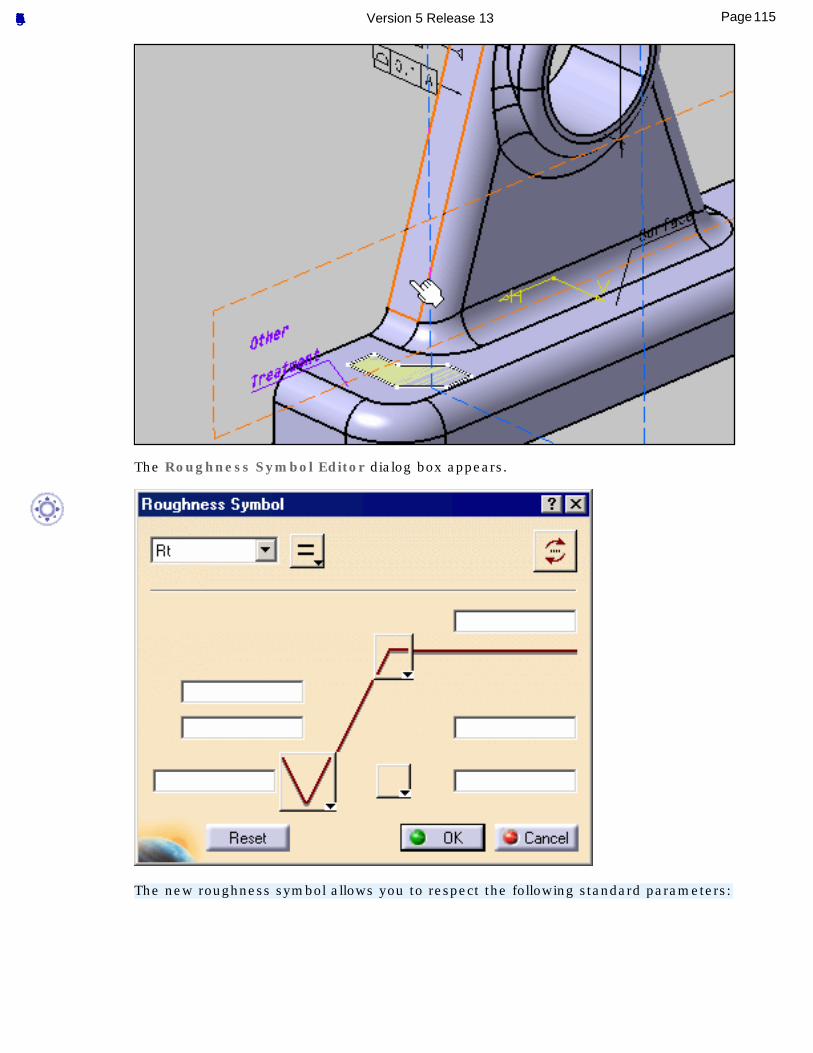
The Roughness Symbol Editor dialog box appears.
The new roughness symbol allows you to respect the following standard parameters:
115Page Functional Tolerancing & Annotation Version 5 Release 13
● ISO
● ASME
● ANSI
● JIS
You can modify these the standard parameters using the Tools -> Standards... command, then selecting the Drafting category.
The old roughness symbols created in previous document are migrated at edition.
If you slide a new roughness symbol outside its reference, an extension line is added. Its overrun is fixed to 2mm and cannot be modified.
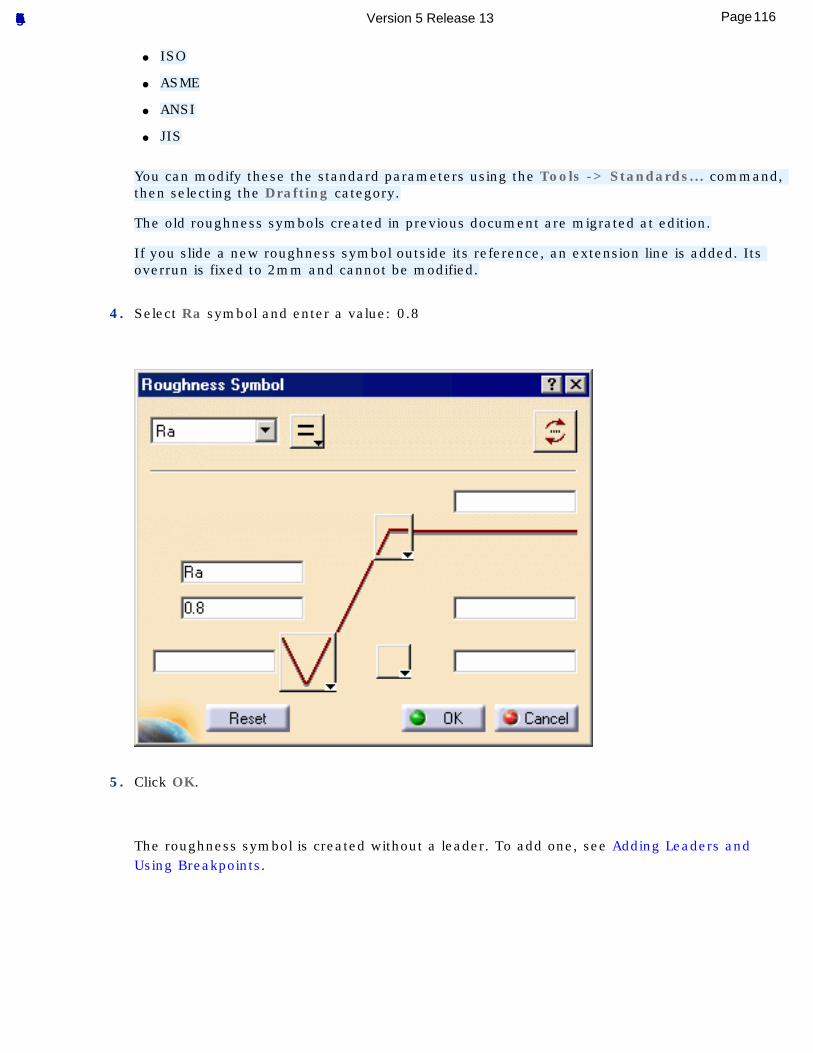
4. Select Ra symbol and enter a value: 0.8
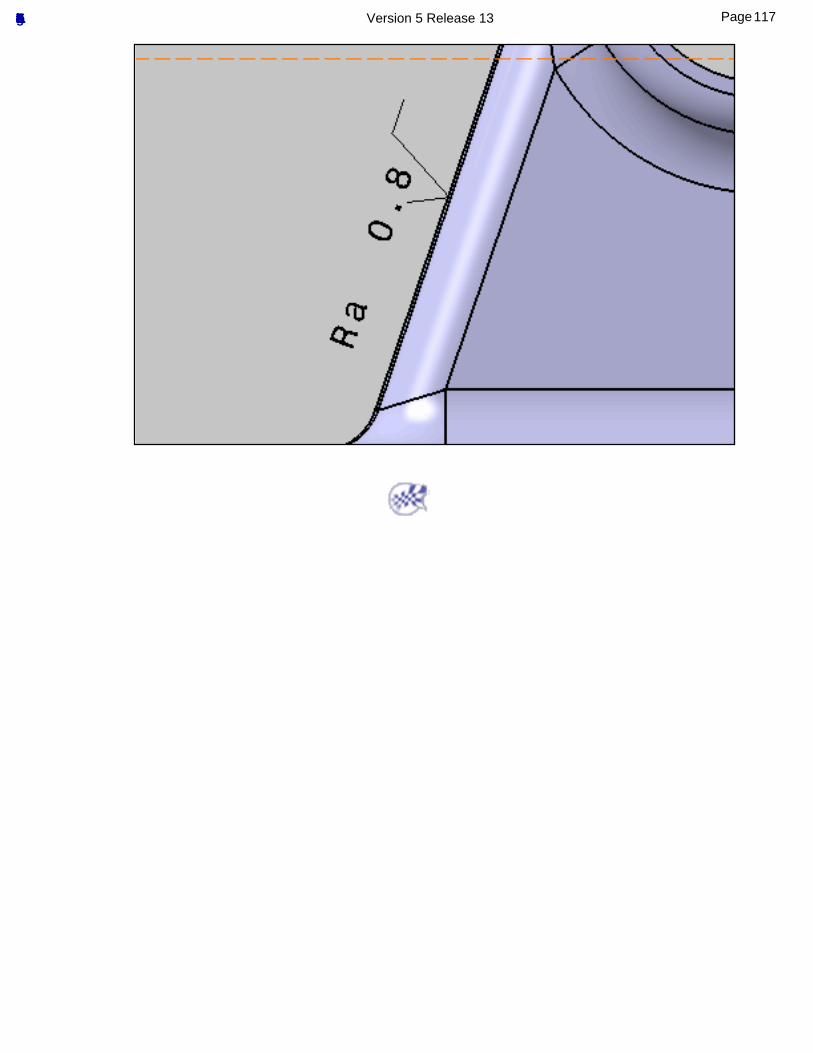
5. Click OK.
The roughness symbol is created without a leader. To add one, see Adding Leaders and Using Breakpoints.
116Page Functional Tolerancing & Annotation Version 5 Release 13
117Page Functional Tolerancing & Annotation Version 5 Release 13
Creating Isolated Annotations
This task shows you how to create isolated annotations, i.e. annotations that are not linked to any geometry.
You can create the following types of isolated annotations:● Text
● Text with Leader
● Text Parallel to Screen
● Flag Note
● Flag Note with Leader
● Datum Element
● Datum Target
● Geometrical Tolerance
● Roughness
● Note Object Attribute (Instantiated from Catalog Browser)
Open the Tolerancing_Annotations_04 CATPart document.
1. Activate the Projected View.1 annotation plane.
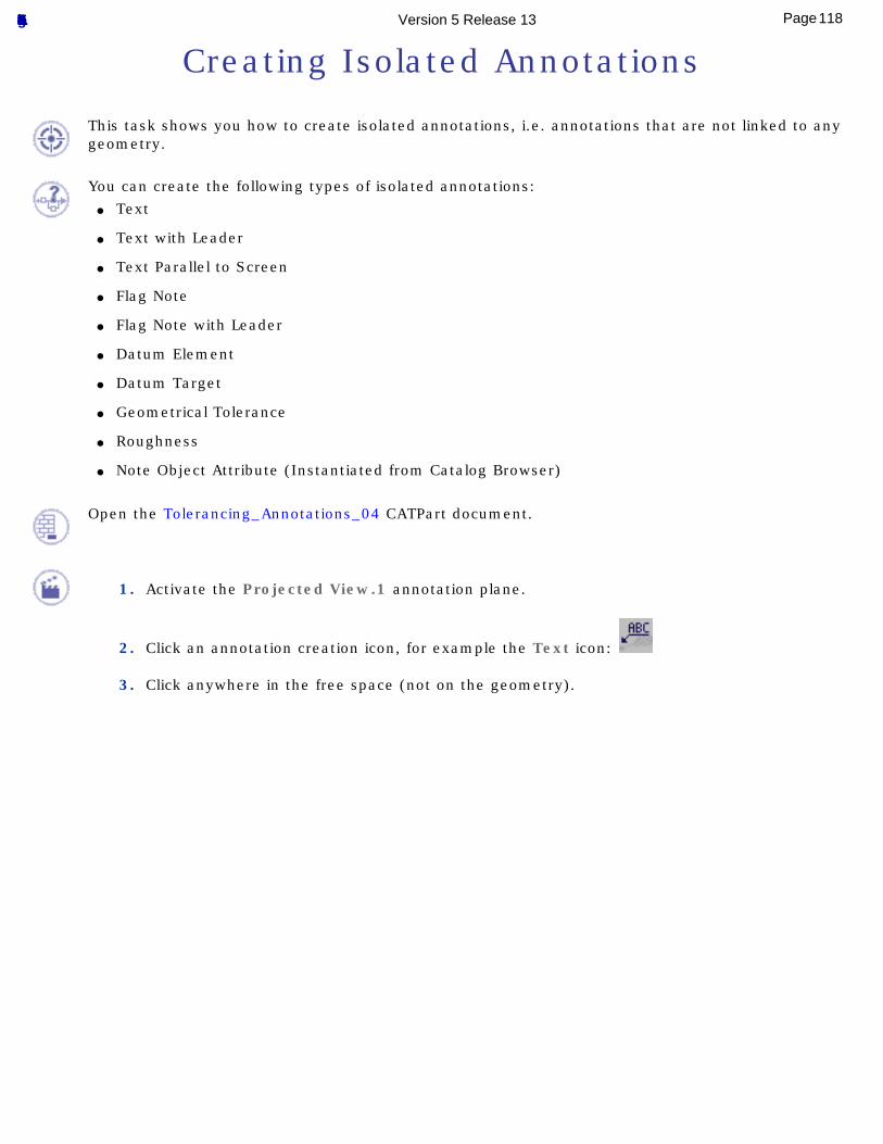
2. Click an annotation creation icon, for example the Text icon:
3. Click anywhere in the free space (not on the geometry).
118Page Functional Tolerancing & Annotation Version 5 Release 13
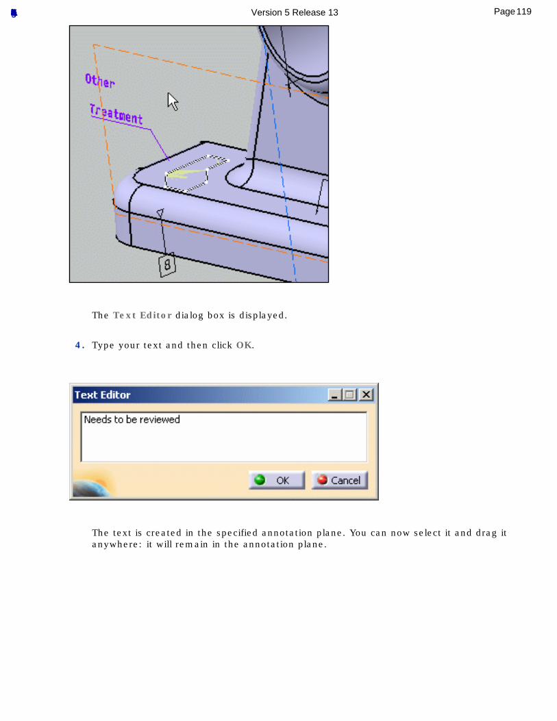
The Text Editor dialog box is displayed.
4. Type your text and then click OK.
The text is created in the specified annotation plane. You can now select it and drag it anywhere: it will remain in the annotation plane.
119Page Functional Tolerancing & Annotation Version 5 Release 13
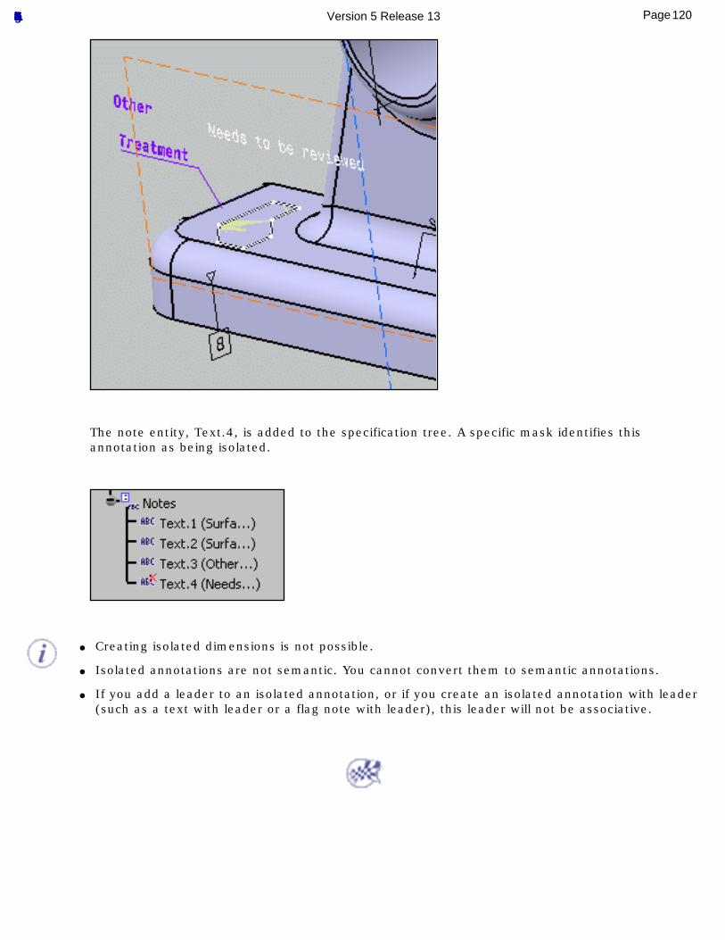
The note entity, Text.4, is added to the specification tree. A specific mask identifies this annotation as being isolated.
● Creating isolated dimensions is not possible.
● Isolated annotations are not semantic. You cannot convert them to semantic annotations.
● If you add a leader to an isolated annotation, or if you create an isolated annotation with leader (such as a text with leader or a flag note with leader), this leader will not be associative.
120Page Functional Tolerancing & Annotation Version 5 Release 13
Creating Dimensions
This task shows you how to create a dimension annotation. See Dimension Units reference for dimension's unit display.
Open the Tolerancing_Annotations_04 CATPart document.
To improve the highlight of the geometry selection, select the Tools->Options... command.In the General category, select the Display sub-category then the Navigation tab and check the option Highlight faces and edges.
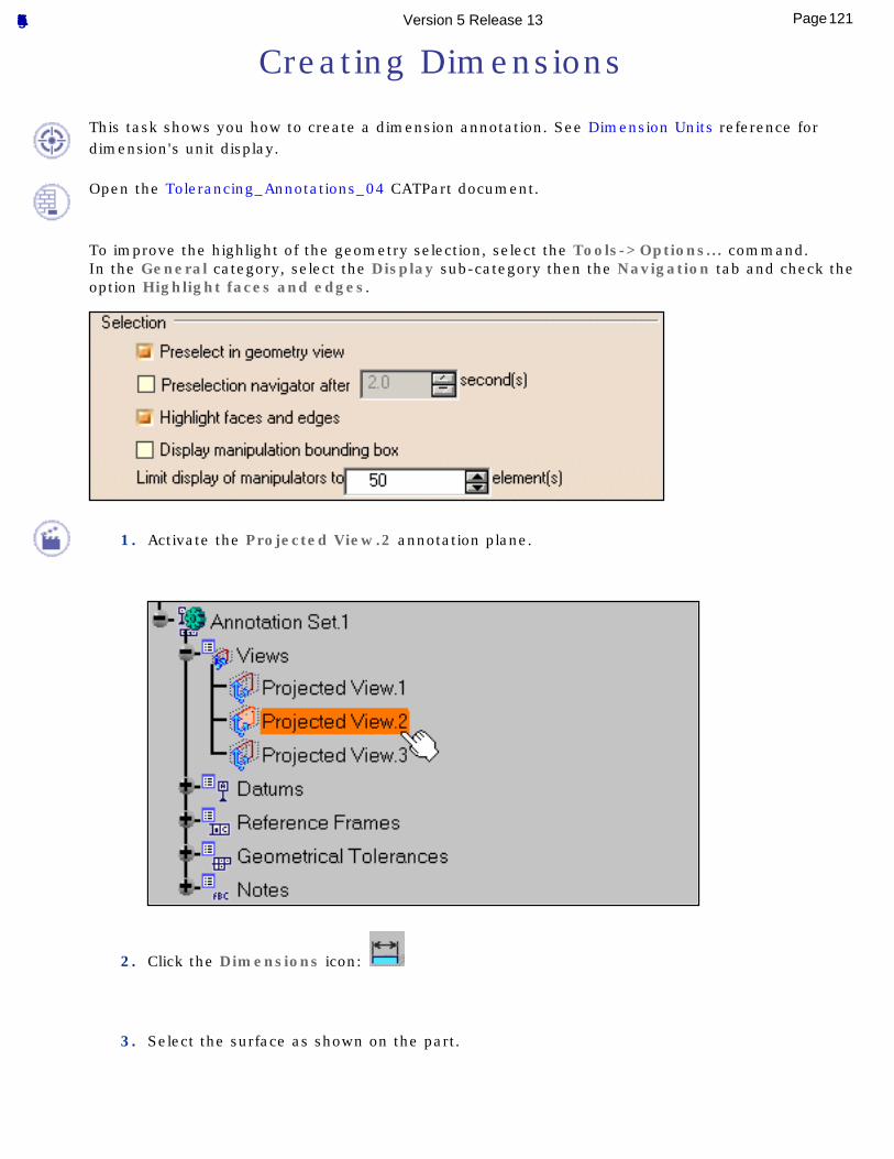
1. Activate the Projected View.2 annotation plane.
2. Click the Dimensions icon:
3. Select the surface as shown on the part.
121Page Functional Tolerancing & Annotation Version 5 Release 13
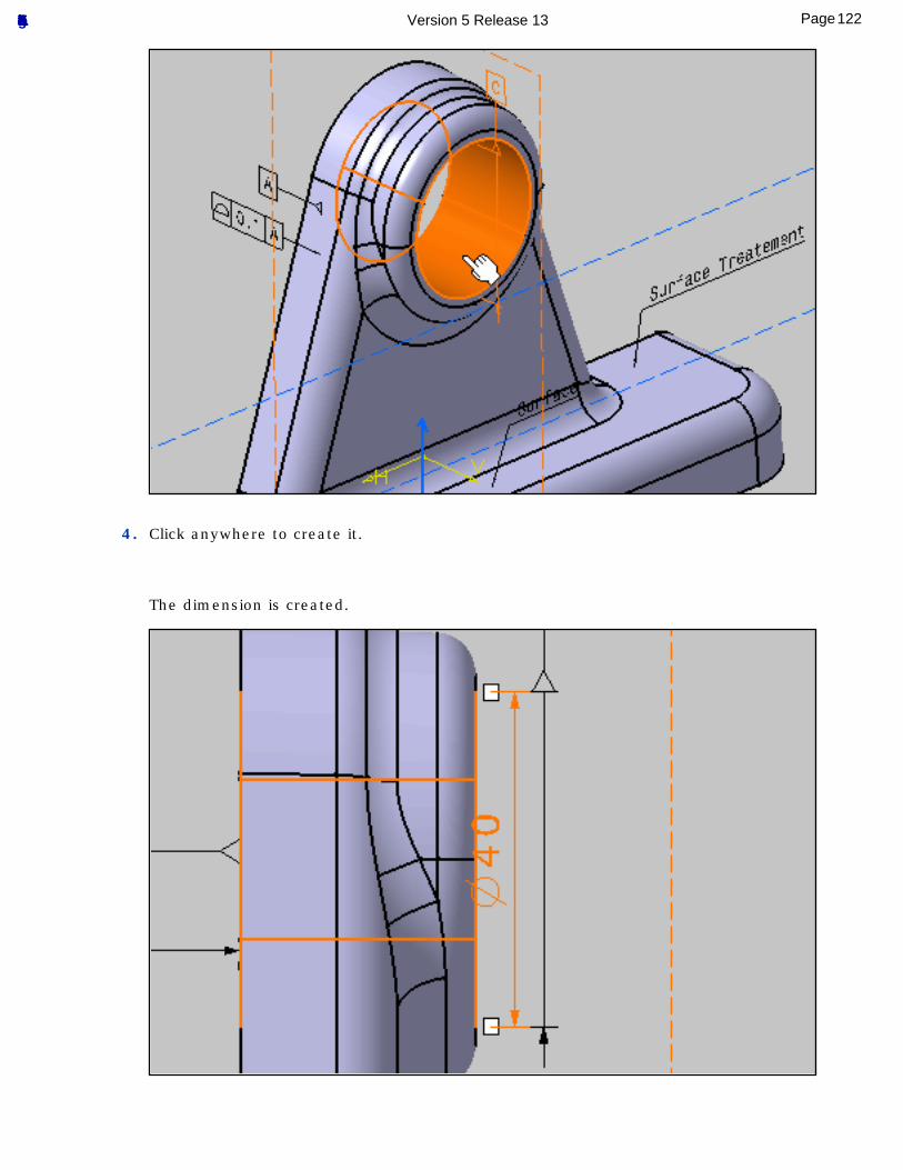
4. Click anywhere to create it.
The dimension is created.
122Page Functional Tolerancing & Annotation Version 5 Release 13
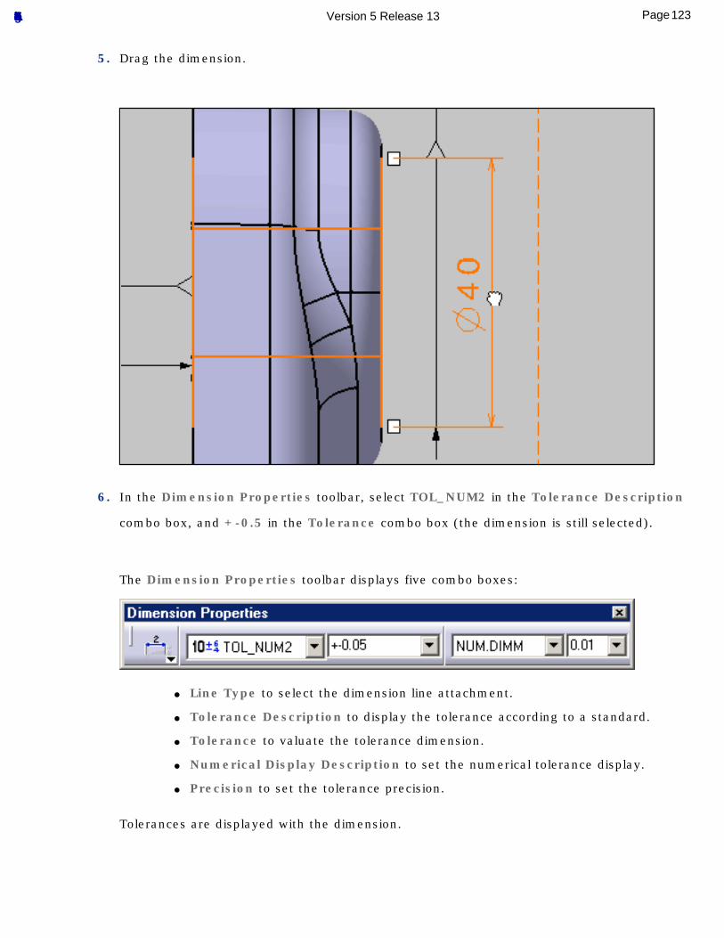
5. Drag the dimension.
6. In the Dimension Properties toolbar, select TOL_NUM2 in the Tolerance Description
combo box, and +-0.5 in the Tolerance combo box (the dimension is still selected).
The Dimension Properties toolbar displays five combo boxes:
● Line Type to select the dimension line attachment.
● Tolerance Description to display the tolerance according to a standard.
● Tolerance to valuate the tolerance dimension.
● Numerical Display Description to set the numerical tolerance display.
● Precision to set the tolerance precision.
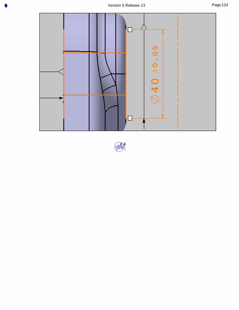
Tolerances are displayed with the dimension.
123Page Functional Tolerancing & Annotation Version 5 Release 13
124Page Functional Tolerancing & Annotation Version 5 Release 13
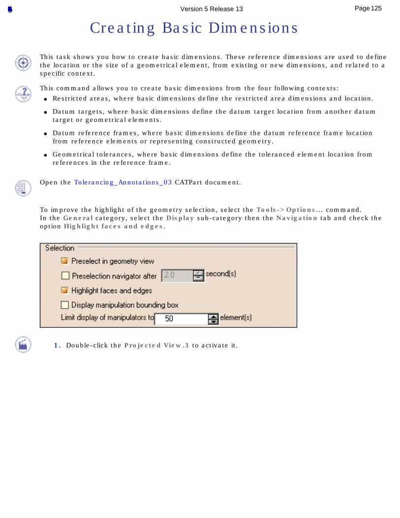
Creating Basic Dimensions
This task shows you how to create basic dimensions. These reference dimensions are used to define the location or the size of a geometrical element, from existing or new dimensions, and related to a specific context.
This command allows you to create basic dimensions from the four following contexts:● Restricted areas, where basic dimensions define the restricted area dimensions and location.
● Datum targets, where basic dimensions define the datum target location from another datum target or geometrical elements.
● Datum reference frames, where basic dimensions define the datum reference frame location from reference elements or representing constructed geometry.
● Geometrical tolerances, where basic dimensions define the toleranced element location from references in the reference frame.
Open the Tolerancing_Annotations_03 CATPart document.
To improve the highlight of the geometry selection, select the Tools->Options... command.In the General category, select the Display sub-category then the Navigation tab and check the option Highlight faces and edges.
1. Double-click the Projected View.3 to activate it.
125Page Functional Tolerancing & Annotation Version 5 Release 13
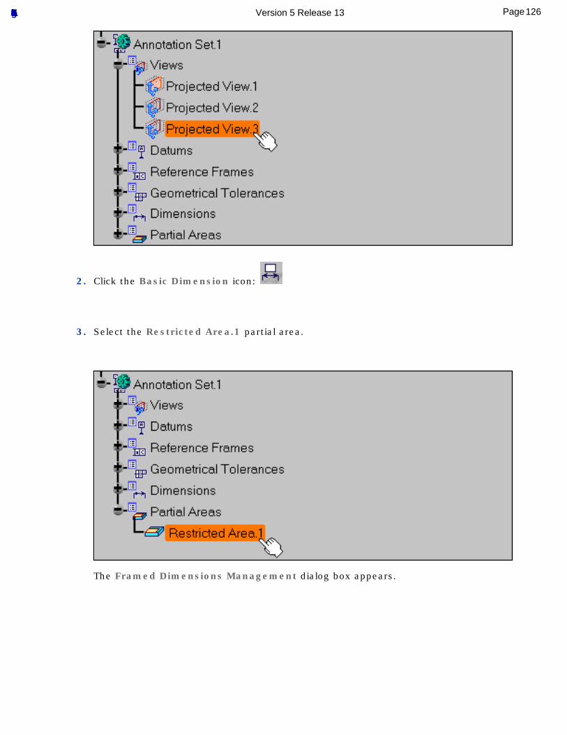
2. Click the Basic Dimension icon:
3. Select the Restricted Area.1 partial area.
The Framed Dimensions Management dialog box appears.
126Page Functional Tolerancing & Annotation Version 5 Release 13
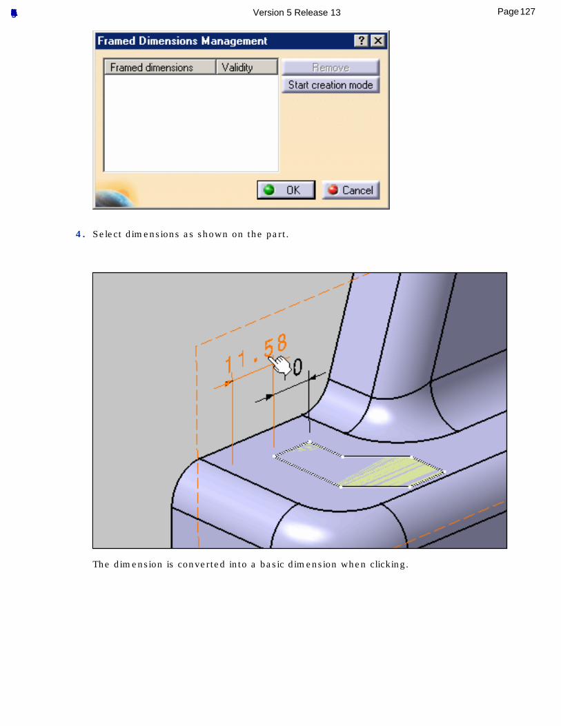
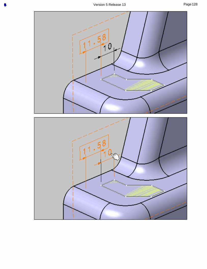
4. Select dimensions as shown on the part.
The dimension is converted into a basic dimension when clicking.
127Page Functional Tolerancing & Annotation Version 5 Release 13
128Page Functional Tolerancing & Annotation Version 5 Release 13
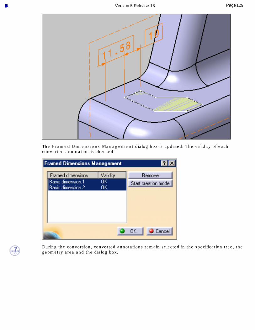
The Framed Dimensions Management dialog box is updated. The validity of each converted annotation is checked.
During the conversion, converted annotations remain selected in the specification tree, the geometry area and the dialog box.
129Page Functional Tolerancing & Annotation Version 5 Release 13
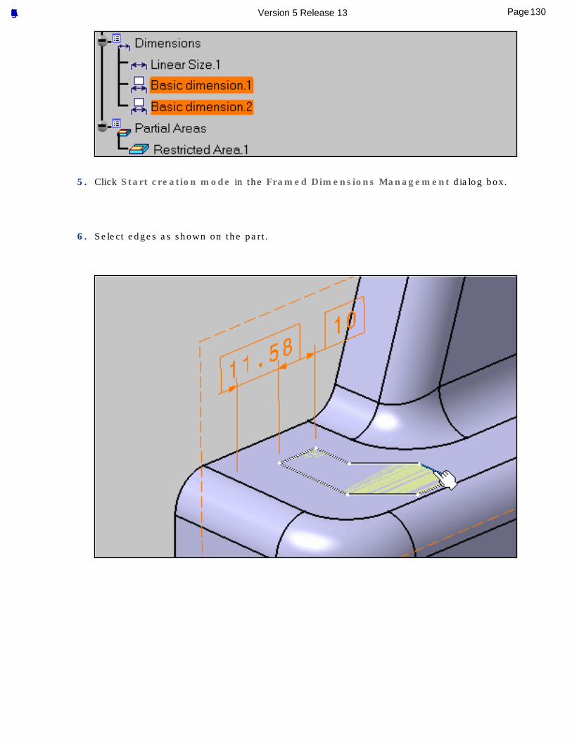
5. Click Start creation mode in the Framed Dimensions Management dialog box.
6. Select edges as shown on the part.
130Page Functional Tolerancing & Annotation Version 5 Release 13
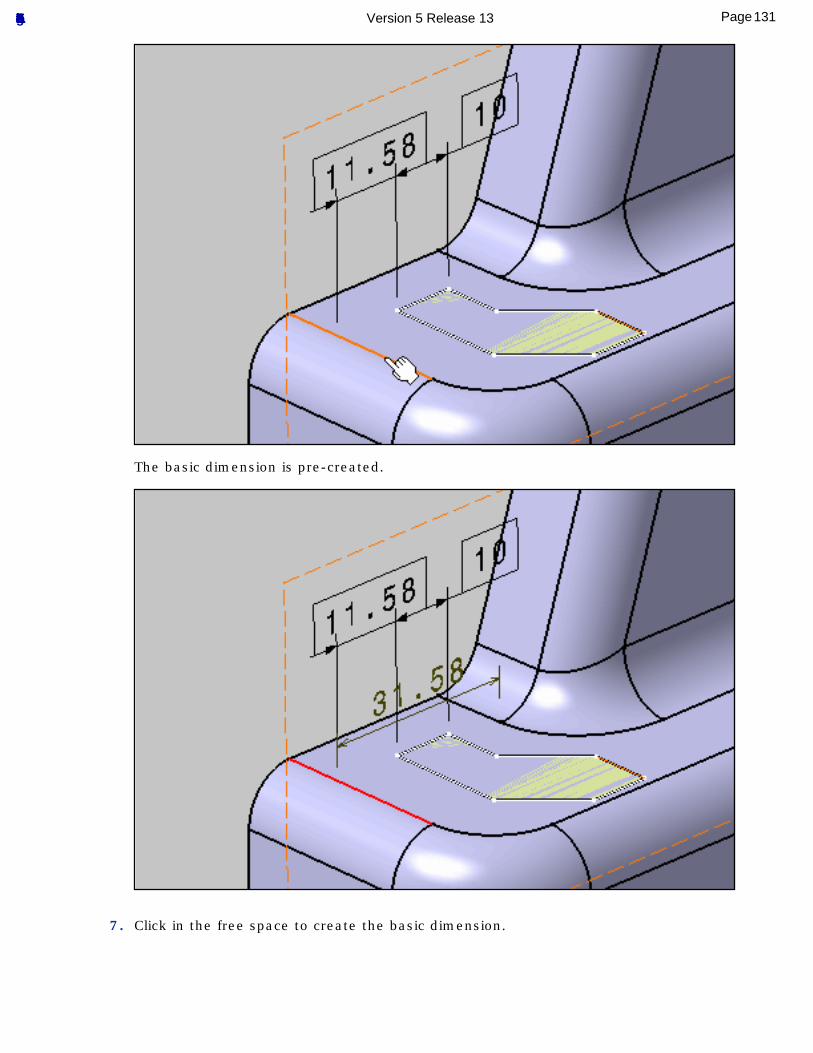
The basic dimension is pre-created.
7. Click in the free space to create the basic dimension.
131Page Functional Tolerancing & Annotation Version 5 Release 13
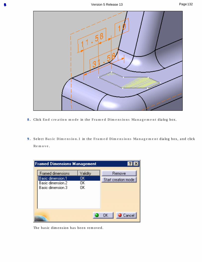
8. Click End creation mode in the Framed Dimensions Management dialog box.
9. Select Basic Dimension.1 in the Framed Dimensions Management dialog box, and click
Remove.
The basic dimension has been removed.
132Page Functional Tolerancing & Annotation Version 5 Release 13
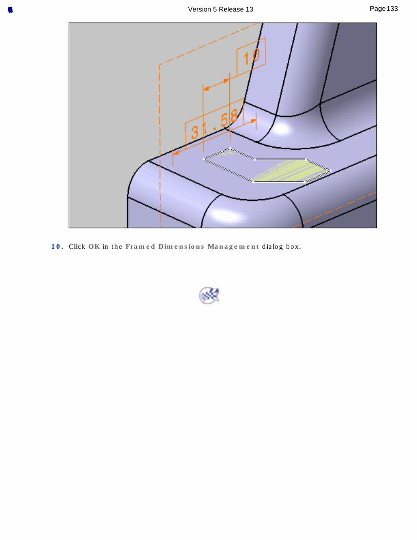
10. Click OK in the Framed Dimensions Management dialog box.
133Page Functional Tolerancing & Annotation Version 5 Release 13
Creating Coordinate Dimensions
This task shows how to create a coordinate dimension based on the coordinates of a selected point. See Dimension Units for more information on dimension unit display.
Open the Tolerancing_Annotations_06 CATPart document.
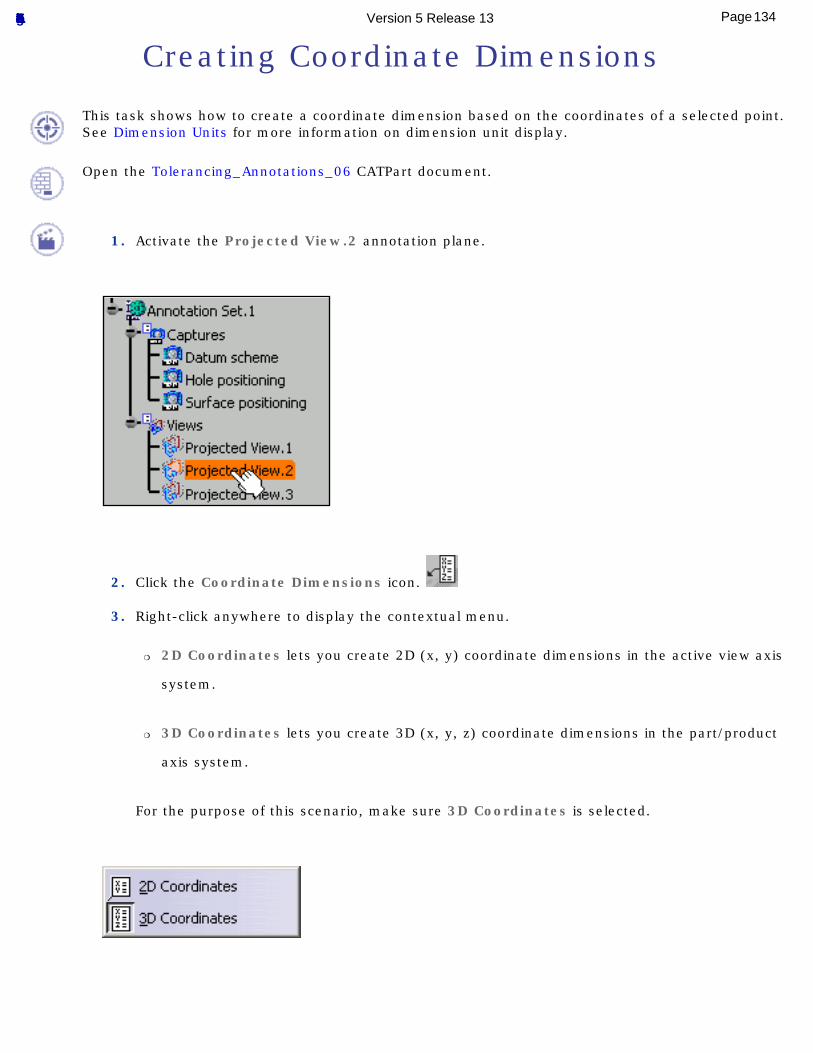
1. Activate the Projected View.2 annotation plane.
2. Click the Coordinate Dimensions icon.
3. Right-click anywhere to display the contextual menu.
❍ 2D Coordinates lets you create 2D (x, y) coordinate dimensions in the active view axis
system.
❍ 3D Coordinates lets you create 3D (x, y, z) coordinate dimensions in the part/product
axis system.
For the purpose of this scenario, make sure 3D Coordinates is selected.
134Page Functional Tolerancing & Annotation Version 5 Release 13
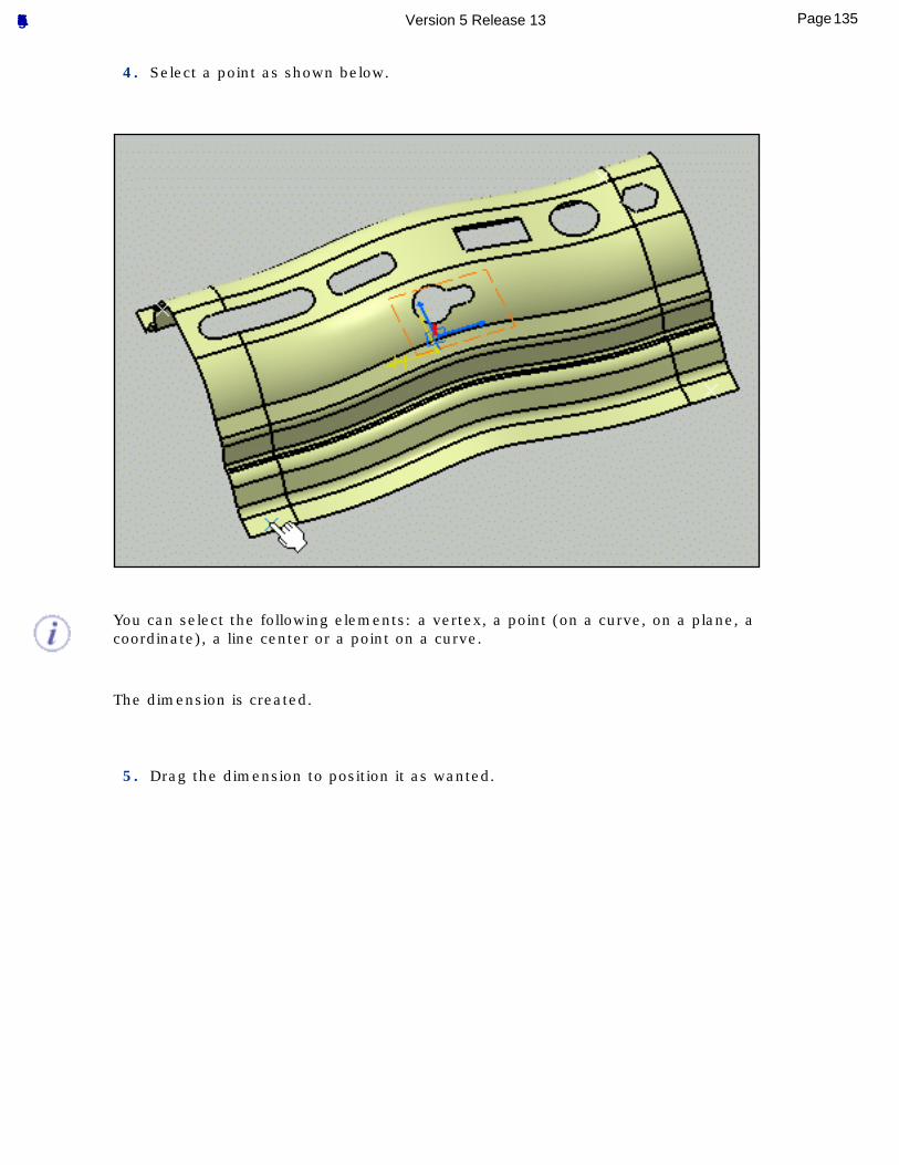
4. Select a point as shown below.
You can select the following elements: a vertex, a point (on a curve, on a plane, a coordinate), a line center or a point on a curve.
The dimension is created.
5. Drag the dimension to position it as wanted.
135Page Functional Tolerancing & Annotation Version 5 Release 13
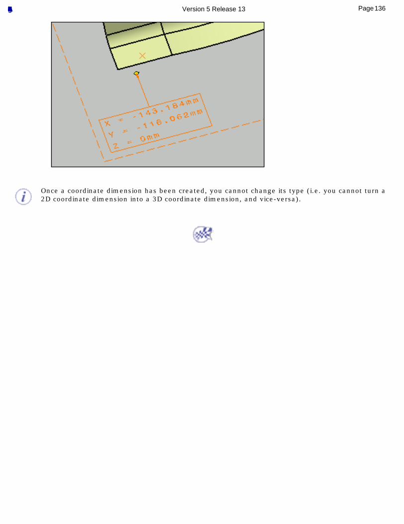
Once a coordinate dimension has been created, you cannot change its type (i.e. you cannot turn a 2D coordinate dimension into a 3D coordinate dimension, and vice-versa).
136Page Functional Tolerancing & Annotation Version 5 Release 13
Creating Stacked Dimensions
This task shows how to create stacked dimensions. See Dimension Units for more information on dimension unit display.
Open the Tolerancing_Annotations_10 CATPart document.
Select Tools -> Options. In the Mechanical Design category, select the Functional Tolerancing & Annotation sub-category, then the Dimension tab and check Align stacked dimension values.
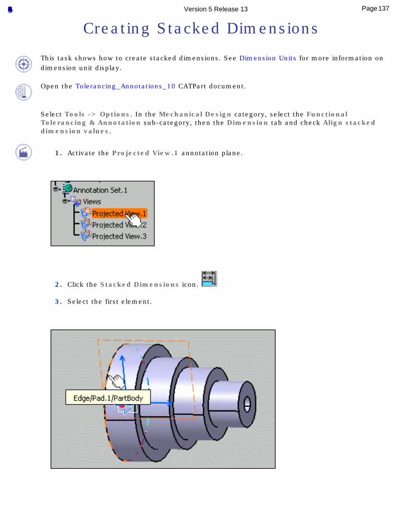
1. Activate the Projected View.1 annotation plane.
2. Click the Stacked Dimensions icon.
3. Select the first element.
137Page Functional Tolerancing & Annotation Version 5 Release 13
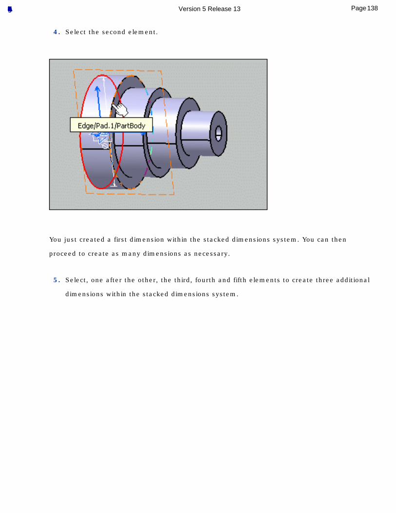
4. Select the second element.
You just created a first dimension within the stacked dimensions system. You can then
proceed to create as many dimensions as necessary.
5. Select, one after the other, the third, fourth and fifth elements to create three additional
dimensions within the stacked dimensions system.
138Page Functional Tolerancing & Annotation Version 5 Release 13
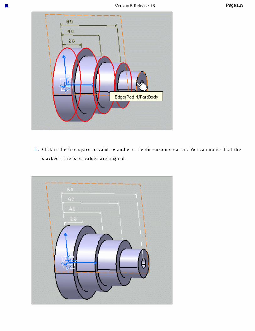
6. Click in the free space to validate and end the dimension creation. You can notice that the
stacked dimension values are aligned.
139Page Functional Tolerancing & Annotation Version 5 Release 13

You can set the dimension properties in the Dimension Properties toolbar as described in
Creating Dimensions.
140Page Functional Tolerancing & Annotation Version 5 Release 13
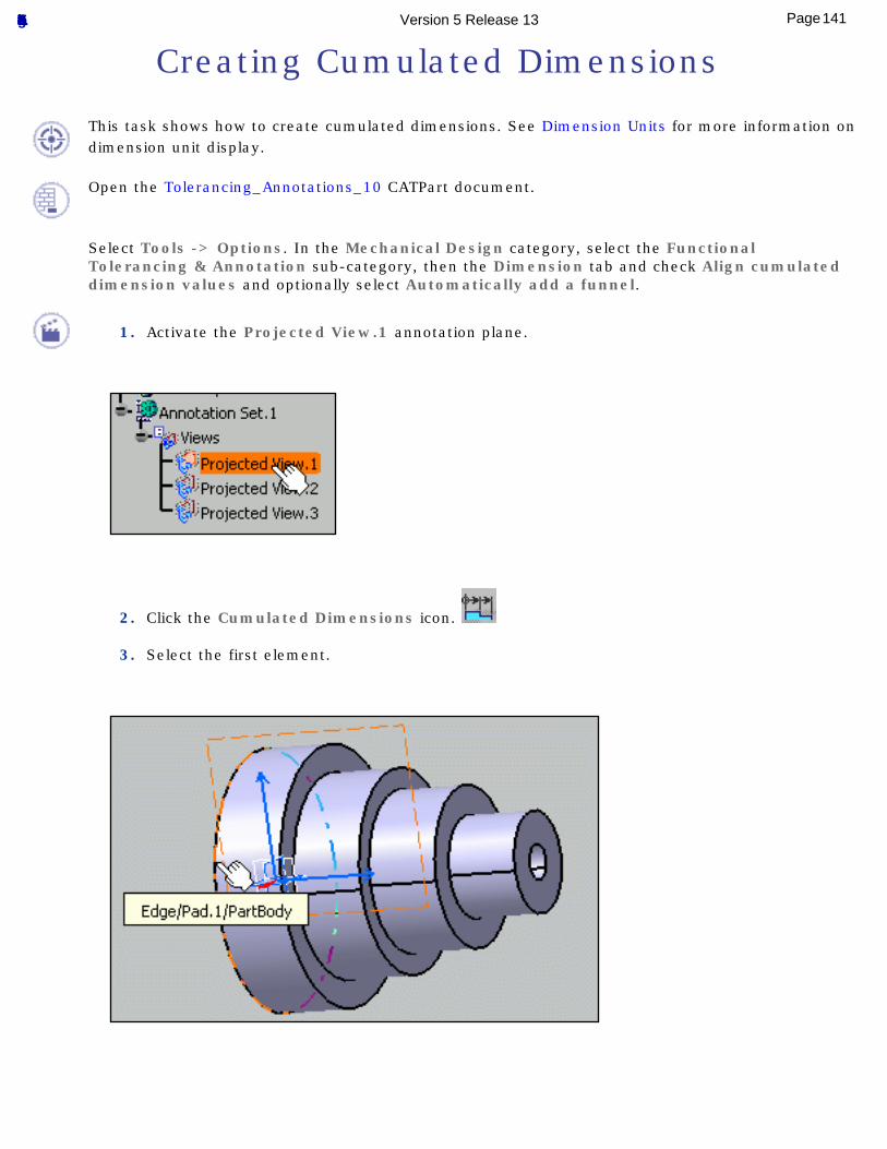
Creating Cumulated Dimensions
This task shows how to create cumulated dimensions. See Dimension Units for more information on dimension unit display.
Open the Tolerancing_Annotations_10 CATPart document.
Select Tools -> Options. In the Mechanical Design category, select the Functional Tolerancing & Annotation sub-category, then the Dimension tab and check Align cumulated dimension values and optionally select Automatically add a funnel.
1. Activate the Projected View.1 annotation plane.
2. Click the Cumulated Dimensions icon.
3. Select the first element.
141Page Functional Tolerancing & Annotation Version 5 Release 13
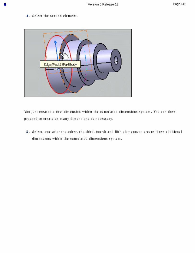
4. Select the second element.
You just created a first dimension within the cumulated dimensions system. You can then
proceed to create as many dimensions as necessary.
5. Select, one after the other, the third, fourth and fifth elements to create three additional
dimensions within the cumulated dimensions system.
142Page Functional Tolerancing & Annotation Version 5 Release 13
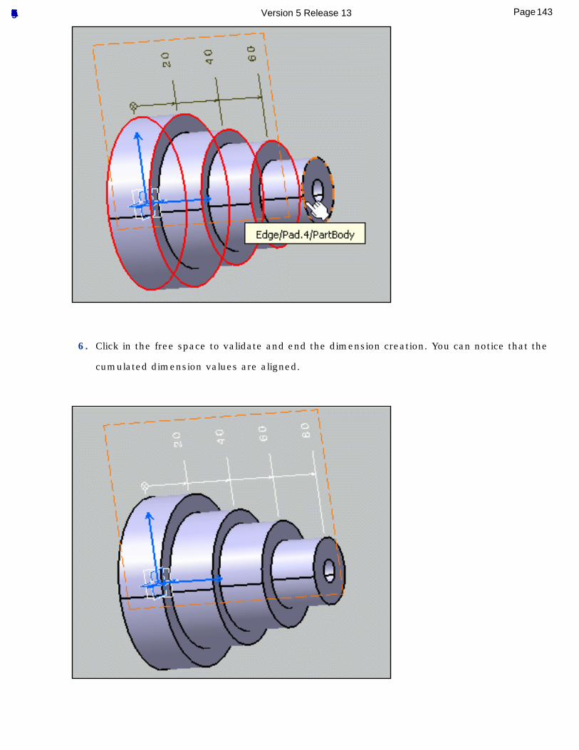
6. Click in the free space to validate and end the dimension creation. You can notice that the
cumulated dimension values are aligned.
143Page Functional Tolerancing & Annotation Version 5 Release 13
You can set the dimension properties in the Dimension Properties toolbar as described in
Creating Dimensions.
144Page Functional Tolerancing & Annotation Version 5 Release 13
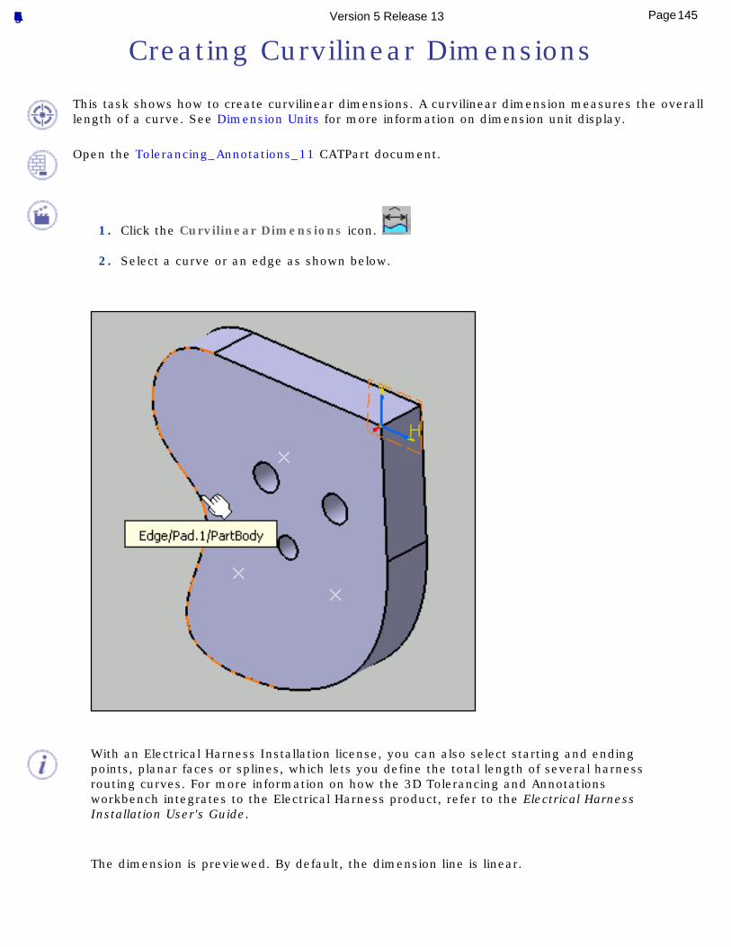
Creating Curvilinear Dimensions
This task shows how to create curvilinear dimensions. A curvilinear dimension measures the overall length of a curve. See Dimension Units for more information on dimension unit display.
Open the Tolerancing_Annotations_11 CATPart document.
1. Click the Curvilinear Dimensions icon.
2. Select a curve or an edge as shown below.
With an Electrical Harness Installation license, you can also select starting and ending points, planar faces or splines, which lets you define the total length of several harness routing curves. For more information on how the 3D Tolerancing and Annotations workbench integrates to the Electrical Harness product, refer to the Electrical Harness Installation User's Guide.
The dimension is previewed. By default, the dimension line is linear.
145Page Functional Tolerancing & Annotation Version 5 Release 13
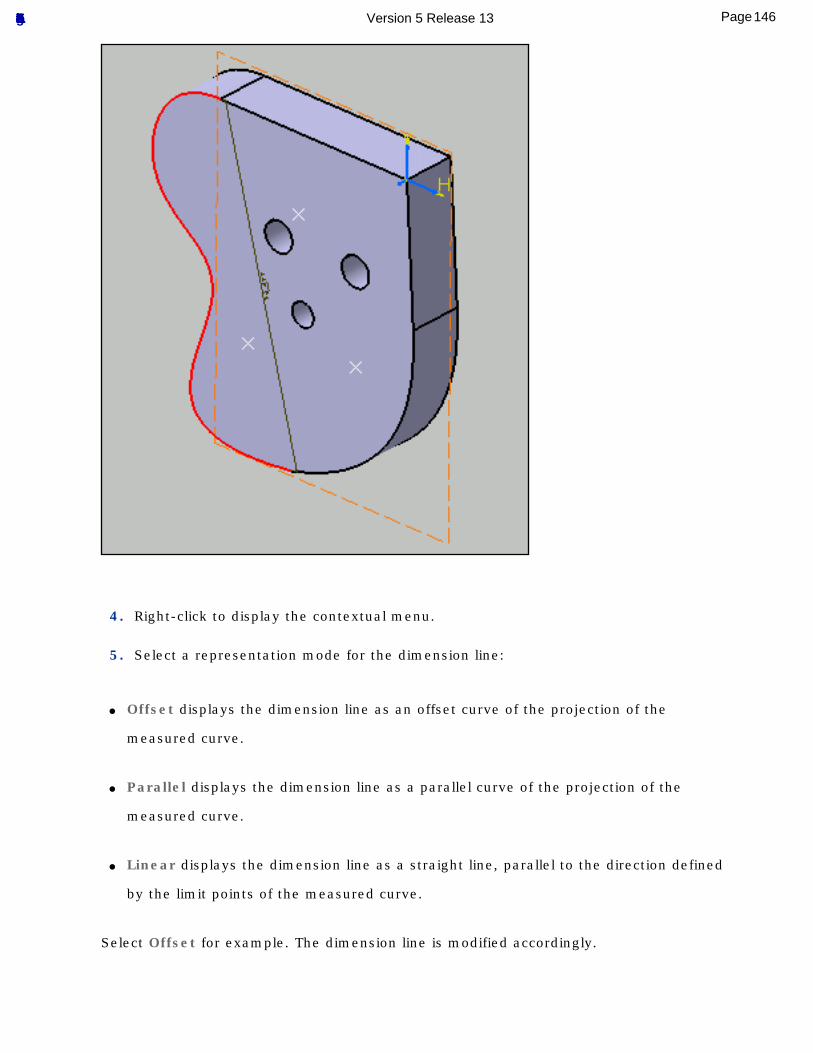
4. Right-click to display the contextual menu.
5. Select a representation mode for the dimension line:
● Offset displays the dimension line as an offset curve of the projection of the
measured curve.
● Parallel displays the dimension line as a parallel curve of the projection of the
measured curve.
● Linear displays the dimension line as a straight line, parallel to the direction defined
by the limit points of the measured curve.
Select Offset for example. The dimension line is modified accordingly.
146Page Functional Tolerancing & Annotation Version 5 Release 13
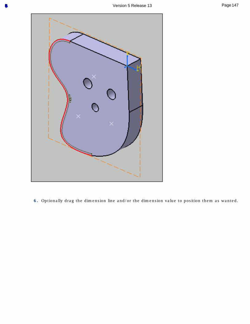
6. Optionally drag the dimension line and/or the dimension value to position them as wanted.
147Page Functional Tolerancing & Annotation Version 5 Release 13
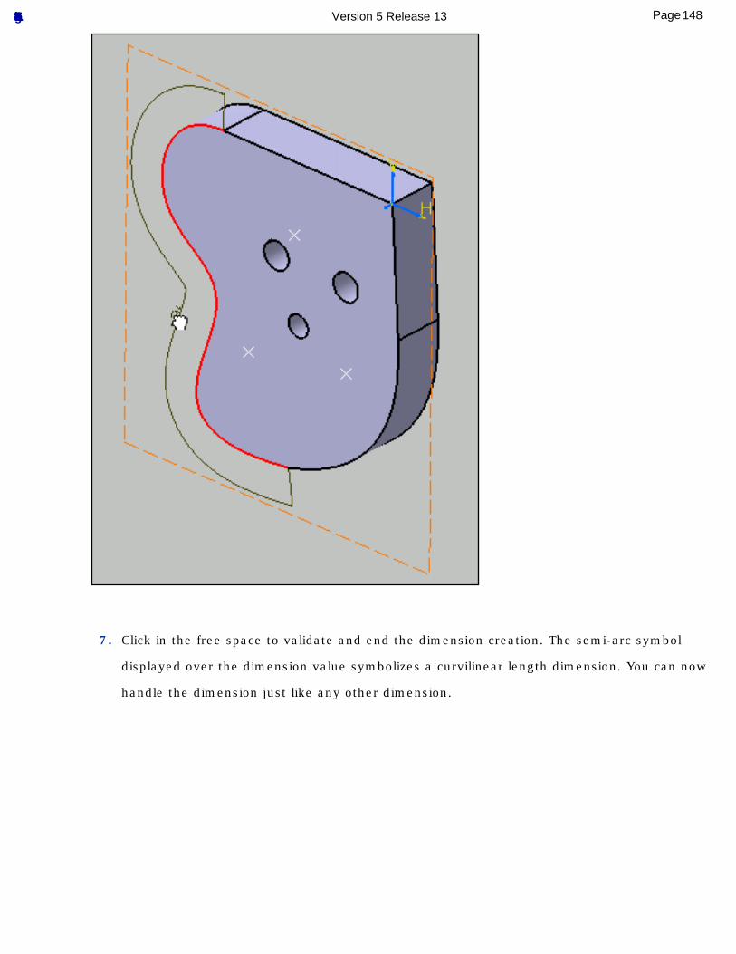
7. Click in the free space to validate and end the dimension creation. The semi-arc symbol
displayed over the dimension value symbolizes a curvilinear length dimension. You can now
handle the dimension just like any other dimension.
148Page Functional Tolerancing & Annotation Version 5 Release 13
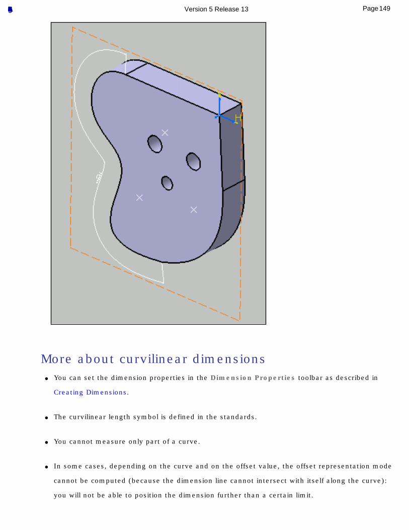
More about curvilinear dimensions● You can set the dimension properties in the Dimension Properties toolbar as described in
Creating Dimensions.
● The curvilinear length symbol is defined in the standards.
● You cannot measure only part of a curve.
● In some cases, depending on the curve and on the offset value, the offset representation mode
cannot be computed (because the dimension line cannot intersect with itself along the curve):
you will not be able to position the dimension further than a certain limit.
149Page Functional Tolerancing & Annotation Version 5 Release 13
● You cannot change the dimension line representation mode after the dimension has been
created.
150Page Functional Tolerancing & Annotation Version 5 Release 13
Generating Dimensions
This task shows you how to generate dimensions automatically.
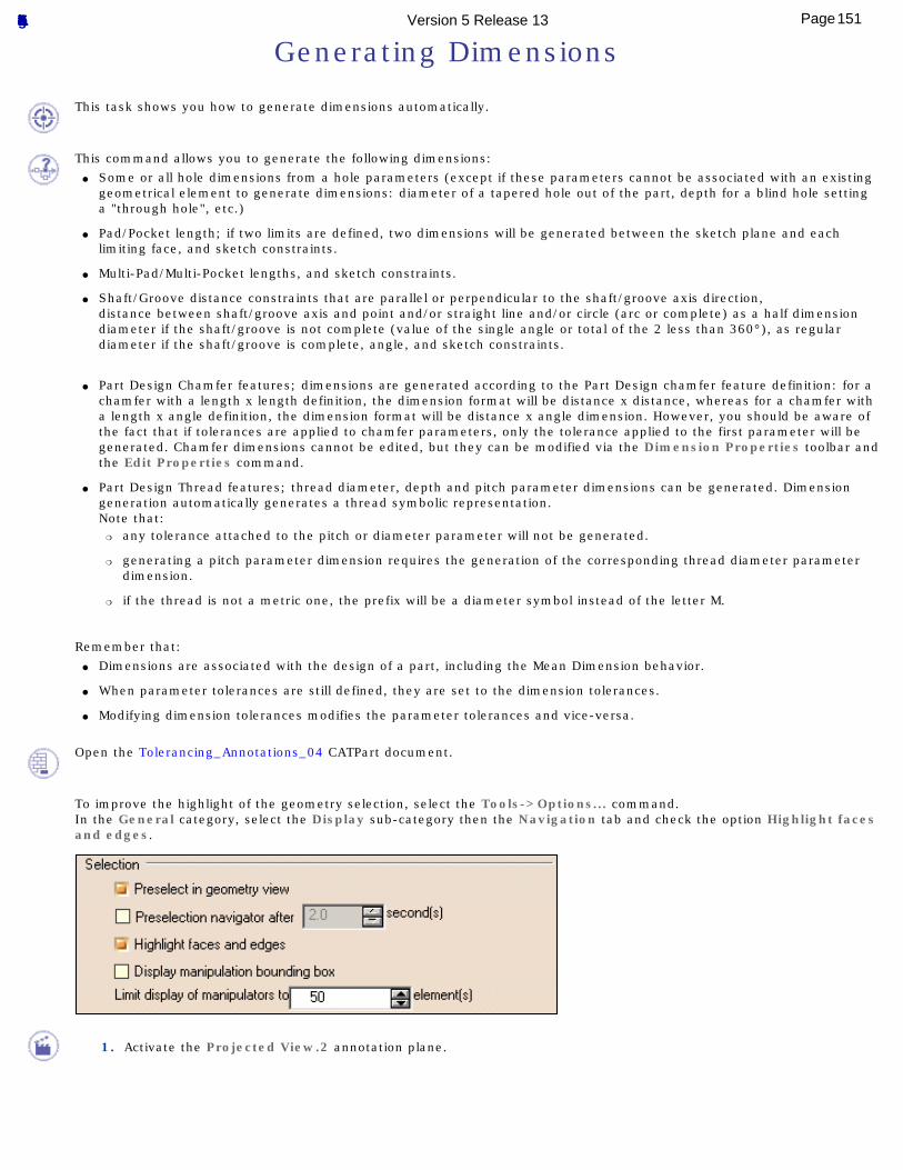
This command allows you to generate the following dimensions:● Some or all hole dimensions from a hole parameters (except if these parameters cannot be associated with an existing
geometrical element to generate dimensions: diameter of a tapered hole out of the part, depth for a blind hole setting a "through hole", etc.)
● Pad/Pocket length; if two limits are defined, two dimensions will be generated between the sketch plane and each limiting face, and sketch constraints.
● Multi-Pad/Multi-Pocket lengths, and sketch constraints.
● Shaft/Groove distance constraints that are parallel or perpendicular to the shaft/groove axis direction,distance between shaft/groove axis and point and/or straight line and/or circle (arc or complete) as a half dimension diameter if the shaft/groove is not complete (value of the single angle or total of the 2 less than 360°), as regular diameter if the shaft/groove is complete, angle, and sketch constraints.
● Part Design Chamfer features; dimensions are generated according to the Part Design chamfer feature definition: for a
chamfer with a length x length definition, the dimension format will be distance x distance, whereas for a chamfer with a length x angle definition, the dimension format will be distance x angle dimension. However, you should be aware of the fact that if tolerances are applied to chamfer parameters, only the tolerance applied to the first parameter will be generated. Chamfer dimensions cannot be edited, but they can be modified via the Dimension Properties toolbar and the Edit Properties command.
● Part Design Thread features; thread diameter, depth and pitch parameter dimensions can be generated. Dimension generation automatically generates a thread symbolic representation.Note that:
❍ any tolerance attached to the pitch or diameter parameter will not be generated.
❍ generating a pitch parameter dimension requires the generation of the corresponding thread diameter parameter dimension.
❍ if the thread is not a metric one, the prefix will be a diameter symbol instead of the letter M.
Remember that:● Dimensions are associated with the design of a part, including the Mean Dimension behavior.
● When parameter tolerances are still defined, they are set to the dimension tolerances.
● Modifying dimension tolerances modifies the parameter tolerances and vice-versa.
Open the Tolerancing_Annotations_04 CATPart document.
To improve the highlight of the geometry selection, select the Tools->Options... command.In the General category, select the Display sub-category then the Navigation tab and check the option Highlight faces and edges.
1. Activate the Projected View.2 annotation plane.
151Page Functional Tolerancing & Annotation Version 5 Release 13
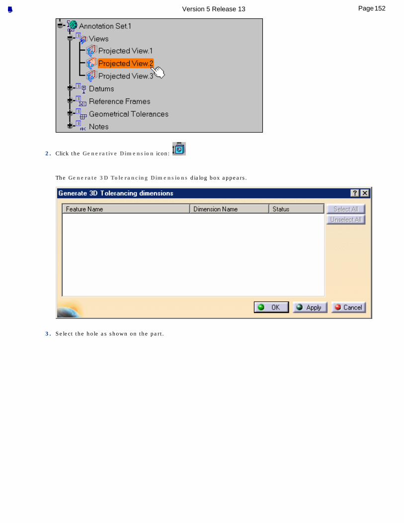
2. Click the Generative Dimension icon:
The Generate 3D Tolerancing Dimensions dialog box appears.
3. Select the hole as shown on the part.
152Page Functional Tolerancing & Annotation Version 5 Release 13
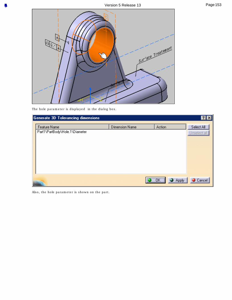
The hole parameter is displayed in the dialog box.
Also, the hole parameter is shown on the part.
153Page Functional Tolerancing & Annotation Version 5 Release 13
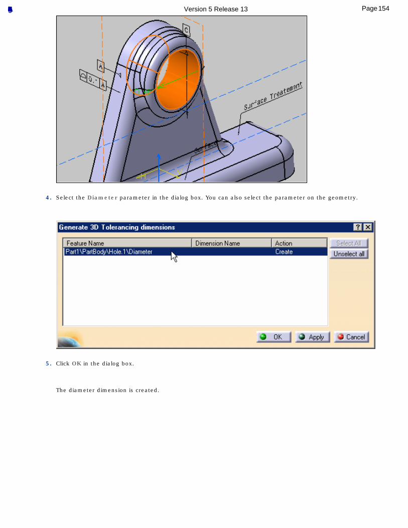
4. Select the Diameter parameter in the dialog box. You can also select the parameter on the geometry.
5. Click OK in the dialog box.
The diameter dimension is created.
154Page Functional Tolerancing & Annotation Version 5 Release 13
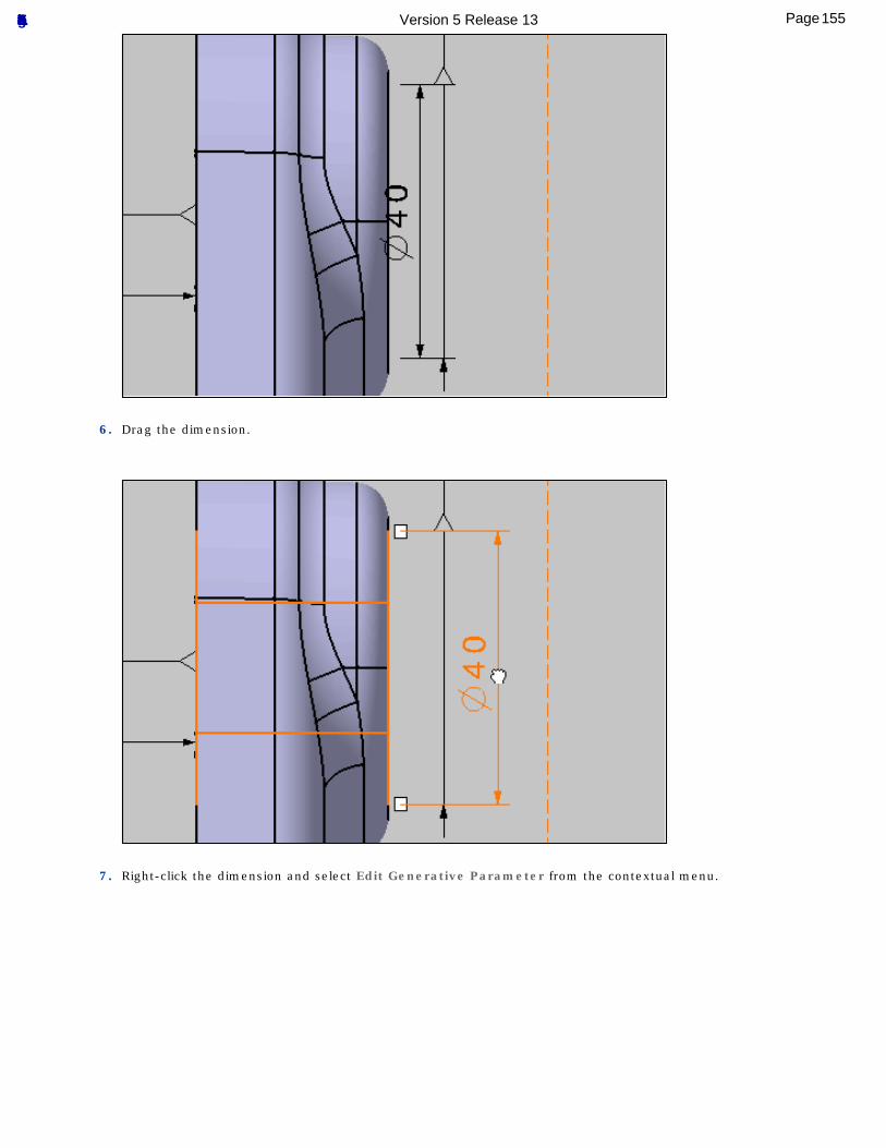
6. Drag the dimension.
7. Right-click the dimension and select Edit Generative Parameter from the contextual menu.
155Page Functional Tolerancing & Annotation Version 5 Release 13
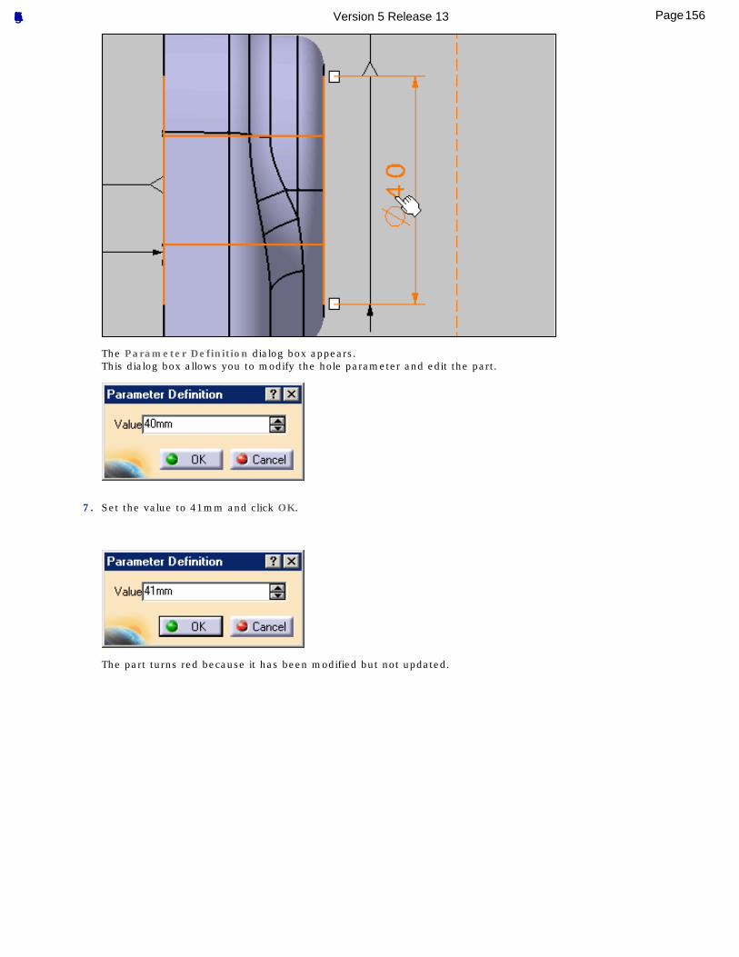
The Parameter Definition dialog box appears.This dialog box allows you to modify the hole parameter and edit the part.
7. Set the value to 41mm and click OK.
The part turns red because it has been modified but not updated.
156Page Functional Tolerancing & Annotation Version 5 Release 13
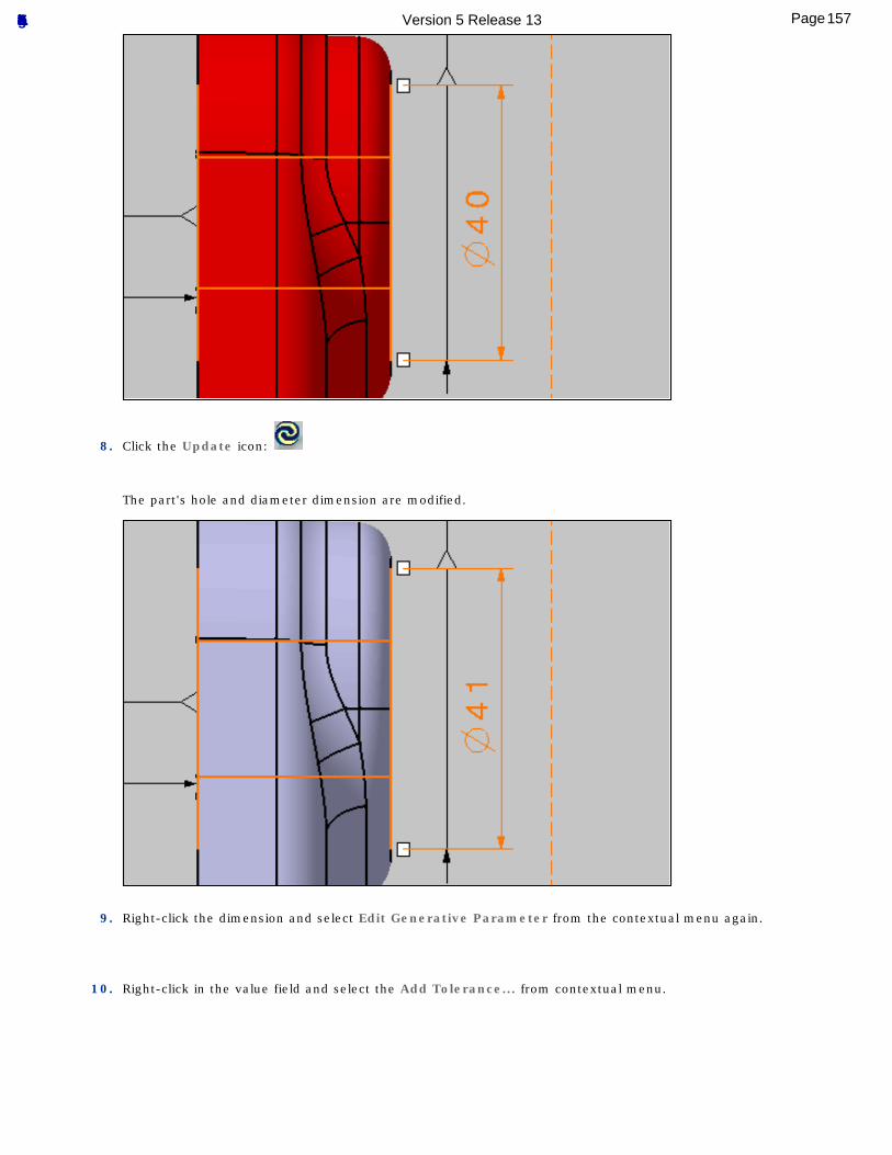
8. Click the Update icon:
The part's hole and diameter dimension are modified.
9. Right-click the dimension and select Edit Generative Parameter from the contextual menu again.
10. Right-click in the value field and select the Add Tolerance... from contextual menu.
157Page Functional Tolerancing & Annotation Version 5 Release 13
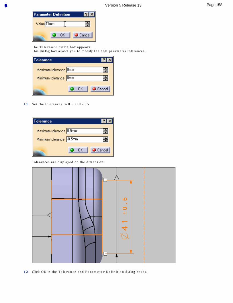
The Tolerance dialog box appears.This dialog box allows you to modify the hole parameter tolerances.
11. Set the tolerances to 0.5 and -0.5
Tolerances are displayed on the dimension.
12. Click OK in the Tolerance and Parameter Definition dialog boxes.
158Page Functional Tolerancing & Annotation Version 5 Release 13
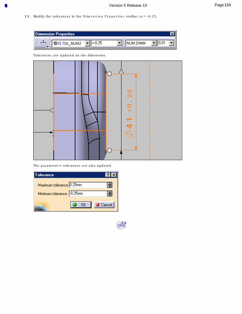
13. Modify the tolerances in the Dimension Properties toolbar to +-0.25.
Tolerances are updated on the dimension.
The parameter's tolerances are also updated.
159Page Functional Tolerancing & Annotation Version 5 Release 13
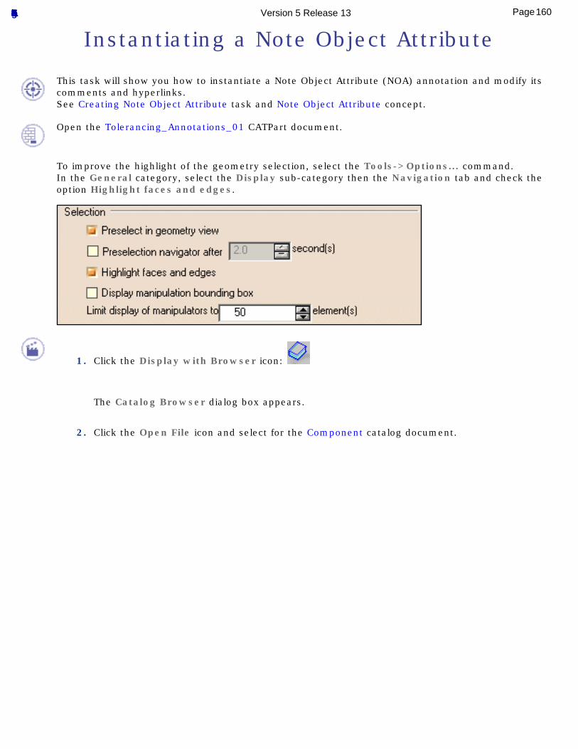
Instantiating a Note Object Attribute
This task will show you how to instantiate a Note Object Attribute (NOA) annotation and modify its comments and hyperlinks.See Creating Note Object Attribute task and Note Object Attribute concept.
Open the Tolerancing_Annotations_01 CATPart document.
To improve the highlight of the geometry selection, select the Tools->Options... command.In the General category, select the Display sub-category then the Navigation tab and check the option Highlight faces and edges.
1. Click the Display with Browser icon:
The Catalog Browser dialog box appears.
2. Click the Open File icon and select for the Component catalog document.
160Page Functional Tolerancing & Annotation Version 5 Release 13
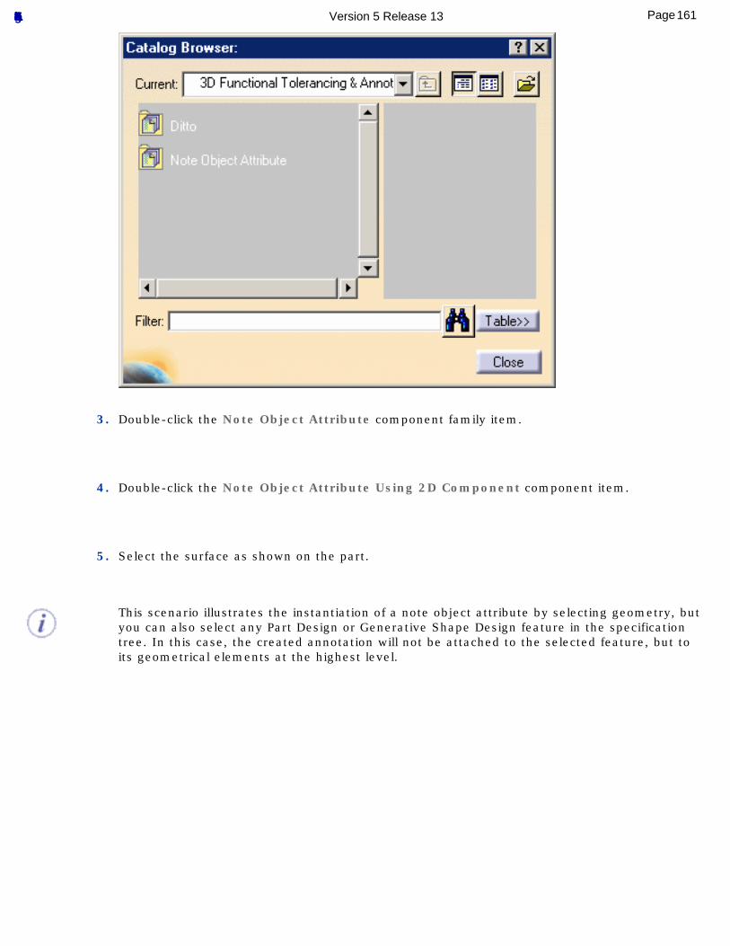
3. Double-click the Note Object Attribute component family item.
4. Double-click the Note Object Attribute Using 2D Component component item.
5. Select the surface as shown on the part.
This scenario illustrates the instantiation of a note object attribute by selecting geometry, but you can also select any Part Design or Generative Shape Design feature in the specification tree. In this case, the created annotation will not be attached to the selected feature, but to its geometrical elements at the highest level.
161Page Functional Tolerancing & Annotation Version 5 Release 13
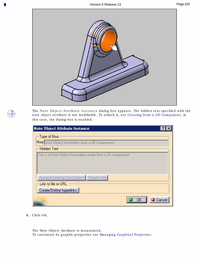
The Note Object Attribute Instance dialog box appears. The hidden text specified with the note object attribute is not modifiable. To unlock it, see Creating from a 2D Component; in this case, the dialog box is enabled.
6. Click OK.
The Note Object Attribute is instantiated.To customize its graphic properties see Managing Graphical Properties.
162Page Functional Tolerancing & Annotation Version 5 Release 13
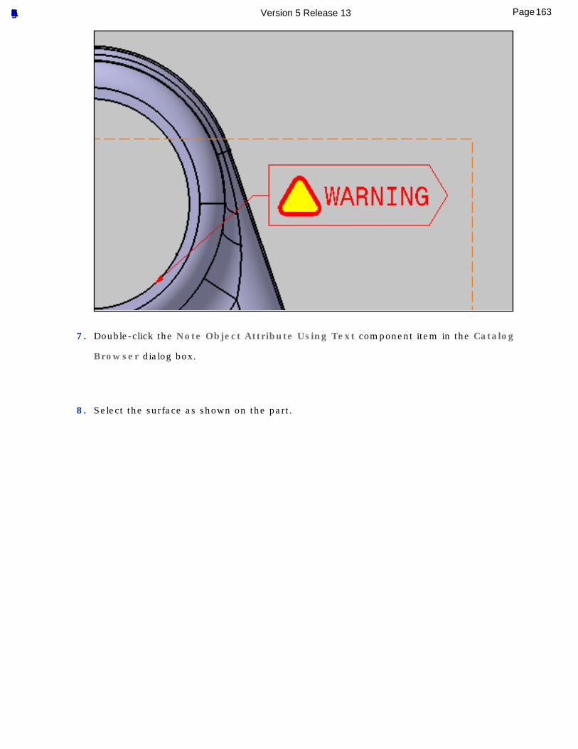
7. Double-click the Note Object Attribute Using Text component item in the Catalog
Browser dialog box.
8. Select the surface as shown on the part.
163Page Functional Tolerancing & Annotation Version 5 Release 13
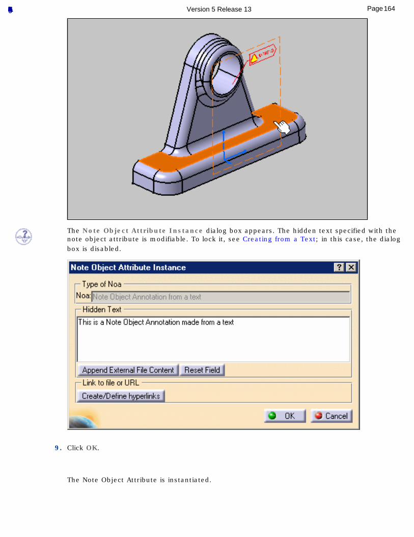
The Note Object Attribute Instance dialog box appears. The hidden text specified with the note object attribute is modifiable. To lock it, see Creating from a Text; in this case, the dialog box is disabled.
9. Click OK.
The Note Object Attribute is instantiated.
164Page Functional Tolerancing & Annotation Version 5 Release 13
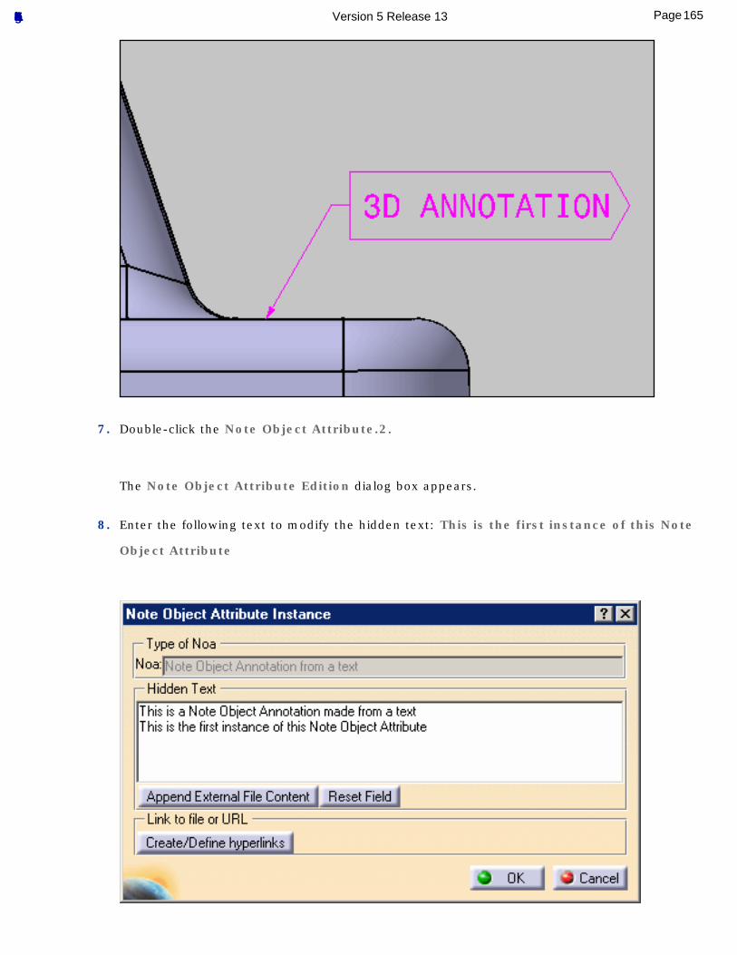
7. Double-click the Note Object Attribute.2.
The Note Object Attribute Edition dialog box appears.
8. Enter the following text to modify the hidden text: This is the first instance of this Note
Object Attribute
165Page Functional Tolerancing & Annotation Version 5 Release 13
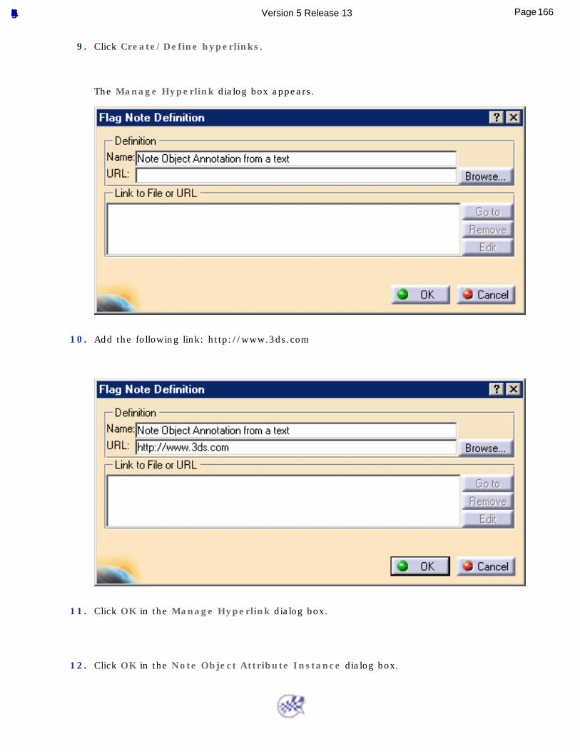
9. Click Create/Define hyperlinks.
The Manage Hyperlink dialog box appears.
10. Add the following link: http://www.3ds.com
11. Click OK in the Manage Hyperlink dialog box.
12. Click OK in the Note Object Attribute Instance dialog box.
166Page Functional Tolerancing & Annotation Version 5 Release 13
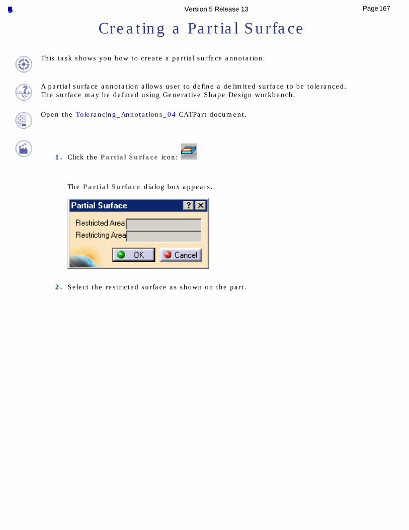
Creating a Partial Surface
This task shows you how to create a partial surface annotation.
A partial surface annotation allows user to define a delimited surface to be toleranced.The surface may be defined using Generative Shape Design workbench.
Open the Tolerancing_Annotations_04 CATPart document.
1. Click the Partial Surface icon:
The Partial Surface dialog box appears.
2. Select the restricted surface as shown on the part.
167Page Functional Tolerancing & Annotation Version 5 Release 13
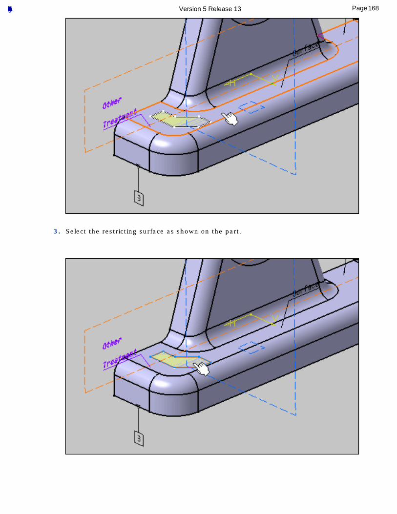
3. Select the restricting surface as shown on the part.
168Page Functional Tolerancing & Annotation Version 5 Release 13
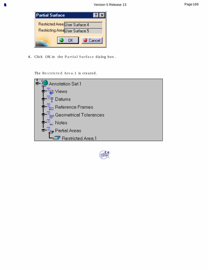
4. Click OK in the Partial Surface dialog box .
The Restricted Area.1 is created.
169Page Functional Tolerancing & Annotation Version 5 Release 13
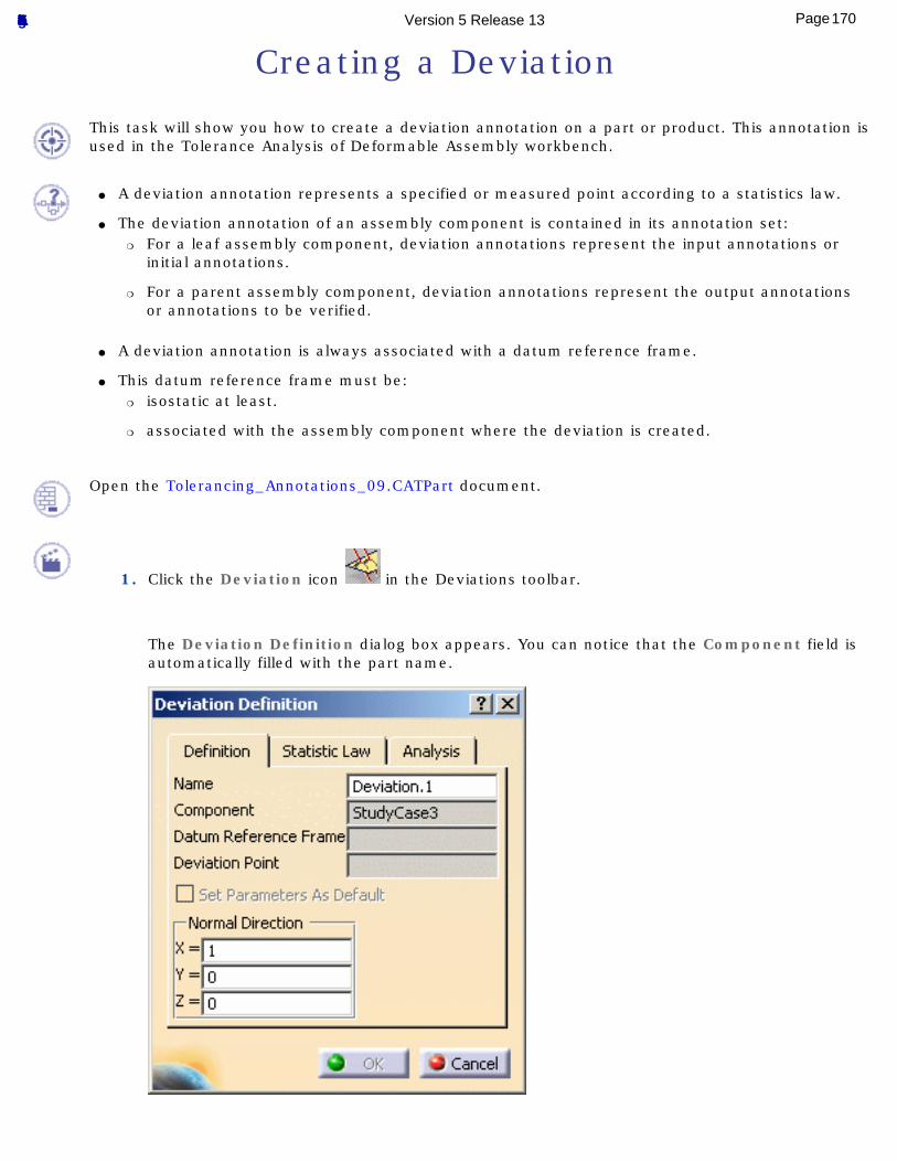
Creating a Deviation
This task will show you how to create a deviation annotation on a part or product. This annotation is used in the Tolerance Analysis of Deformable Assembly workbench.
● A deviation annotation represents a specified or measured point according to a statistics law.
● The deviation annotation of an assembly component is contained in its annotation set:❍ For a leaf assembly component, deviation annotations represent the input annotations or
initial annotations.
❍ For a parent assembly component, deviation annotations represent the output annotations or annotations to be verified.
● A deviation annotation is always associated with a datum reference frame.
● This datum reference frame must be:❍ isostatic at least.
❍ associated with the assembly component where the deviation is created.
Open the Tolerancing_Annotations_09.CATPart document.
1. Click the Deviation icon in the Deviations toolbar.
The Deviation Definition dialog box appears. You can notice that the Component field is automatically filled with the part name.
170Page Functional Tolerancing & Annotation Version 5 Release 13
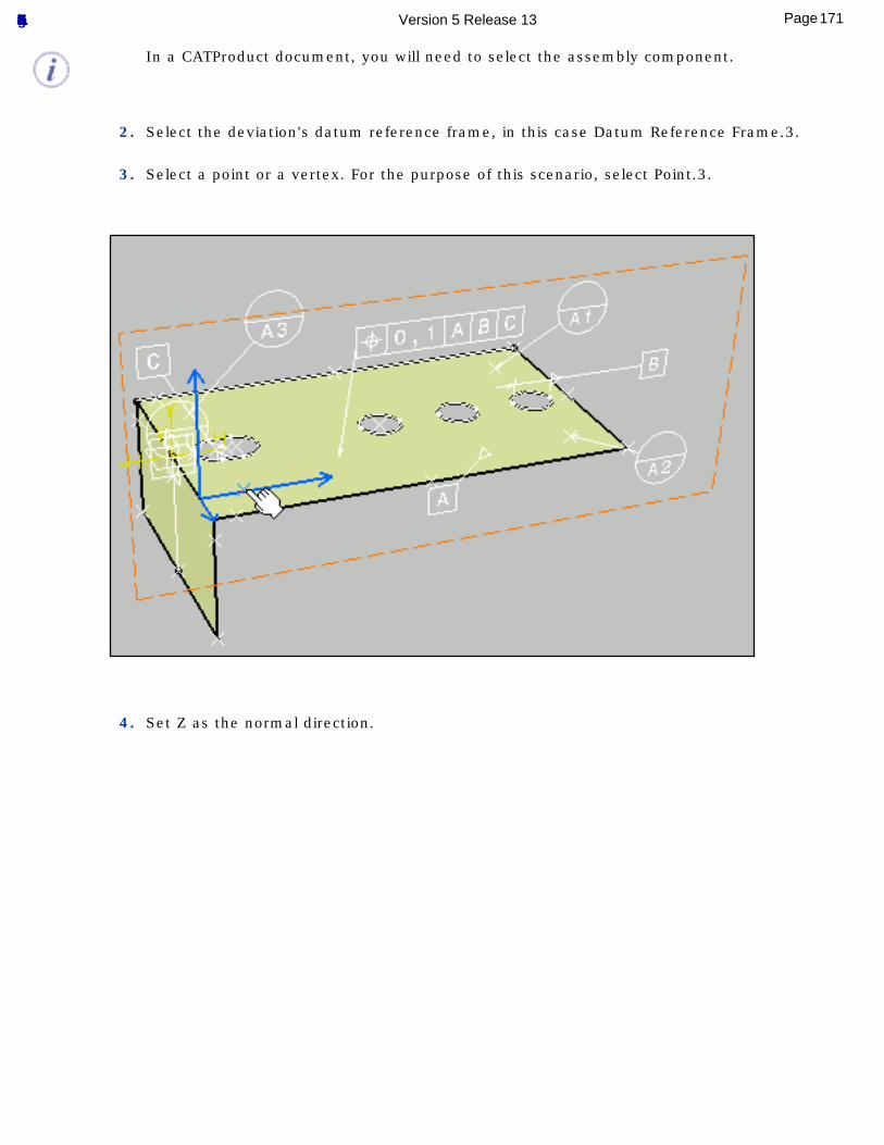
In a CATProduct document, you will need to select the assembly component.
2. Select the deviation's datum reference frame, in this case Datum Reference Frame.3.
3. Select a point or a vertex. For the purpose of this scenario, select Point.3.
4. Set Z as the normal direction.
171Page Functional Tolerancing & Annotation Version 5 Release 13
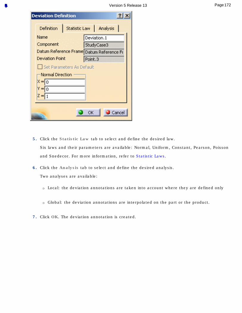
5. Click the Statistic Law tab to select and define the desired law.
Six laws and their parameters are available: Normal, Uniform, Constant, Pearson, Poisson
and Snedecor. For more information, refer to Statistic Laws.
6. Click the Analysis tab to select and define the desired analysis.
Two analyses are available:
❍ Local: the deviation annotations are taken into account where they are defined only
❍ Global: the deviation annotations are interpolated on the part or the product.
7. Click OK. The deviation annotation is created.
172Page Functional Tolerancing & Annotation Version 5 Release 13
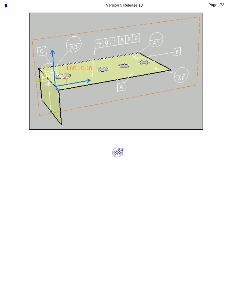
173Page Functional Tolerancing & Annotation Version 5 Release 13
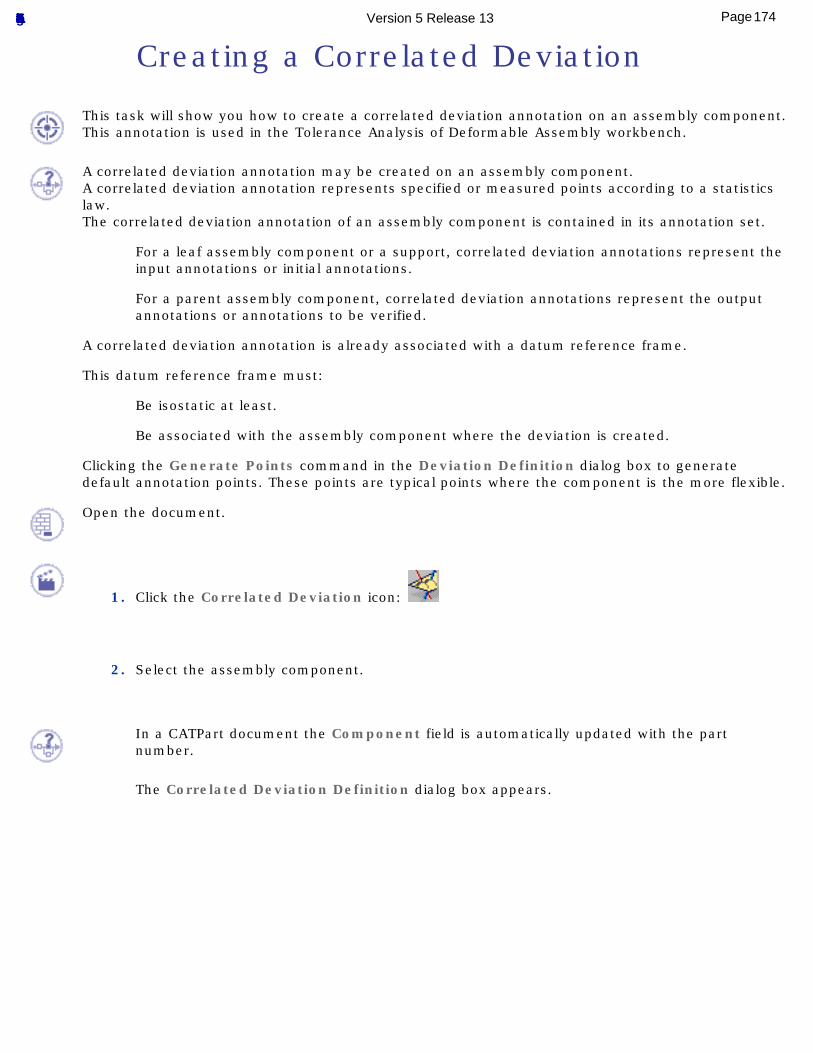
Creating a Correlated Deviation
This task will show you how to create a correlated deviation annotation on an assembly component. This annotation is used in the Tolerance Analysis of Deformable Assembly workbench.
A correlated deviation annotation may be created on an assembly component.A correlated deviation annotation represents specified or measured points according to a statistics law.The correlated deviation annotation of an assembly component is contained in its annotation set.
For a leaf assembly component or a support, correlated deviation annotations represent the input annotations or initial annotations.
For a parent assembly component, correlated deviation annotations represent the output annotations or annotations to be verified.
A correlated deviation annotation is already associated with a datum reference frame.
This datum reference frame must:
Be isostatic at least.
Be associated with the assembly component where the deviation is created.
Clicking the Generate Points command in the Deviation Definition dialog box to generate default annotation points. These points are typical points where the component is the more flexible.
Open the document.
1. Click the Correlated Deviation icon:
2. Select the assembly component.
In a CATPart document the Component field is automatically updated with the part number.
The Correlated Deviation Definition dialog box appears.
174Page Functional Tolerancing & Annotation Version 5 Release 13
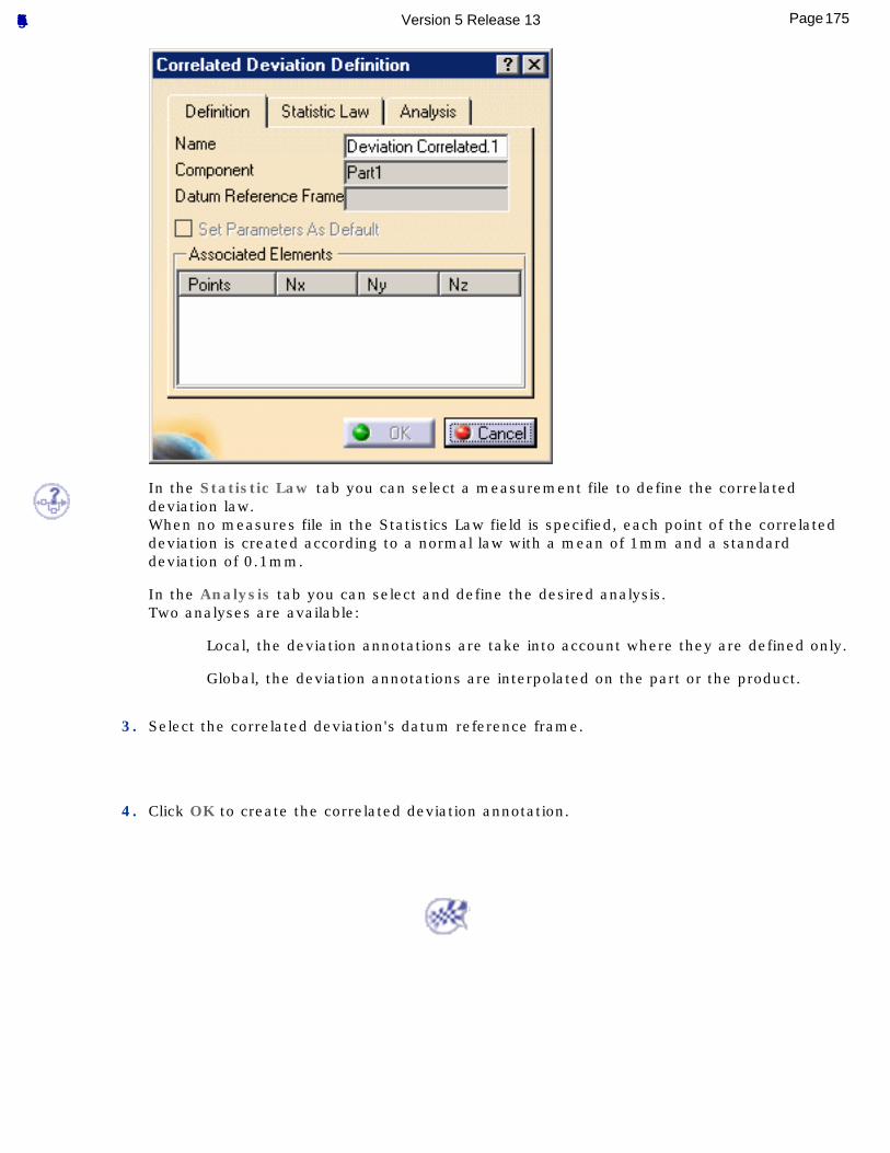
In the Statistic Law tab you can select a measurement file to define the correlated deviation law.When no measures file in the Statistics Law field is specified, each point of the correlated deviation is created according to a normal law with a mean of 1mm and a standard deviation of 0.1mm.
In the Analysis tab you can select and define the desired analysis.Two analyses are available:
Local, the deviation annotations are take into account where they are defined only.
Global, the deviation annotations are interpolated on the part or the product.
3. Select the correlated deviation's datum reference frame.
4. Click OK to create the correlated deviation annotation.
175Page Functional Tolerancing & Annotation Version 5 Release 13
Creating a Distance Between Two Points
This task will show you how to create a distance between two points annotation between two points of an assembly component or two assembly components. This annotation is used in the Tolerance Analysis of Deformable Assembly workbench.
Distance between two points annotation represents a distance to be checked between two points.The distance between two points annotation of an assembly component is contained in the component's annotation set.Distance between two points annotation represent the an output annotation or an annotation to be verified.
A distance between two points annotation is already associated with a positioning system or a datum reference frame.
This datum reference frame must:
Be isostatic at least.
Be associated with the assembly component where the deviation is created.
Open the document.
1. Click the Distance Between Two Points icon:
2. Select the assembly component.
The Distance Between Two Points dialog box appears.
176Page Functional Tolerancing & Annotation Version 5 Release 13
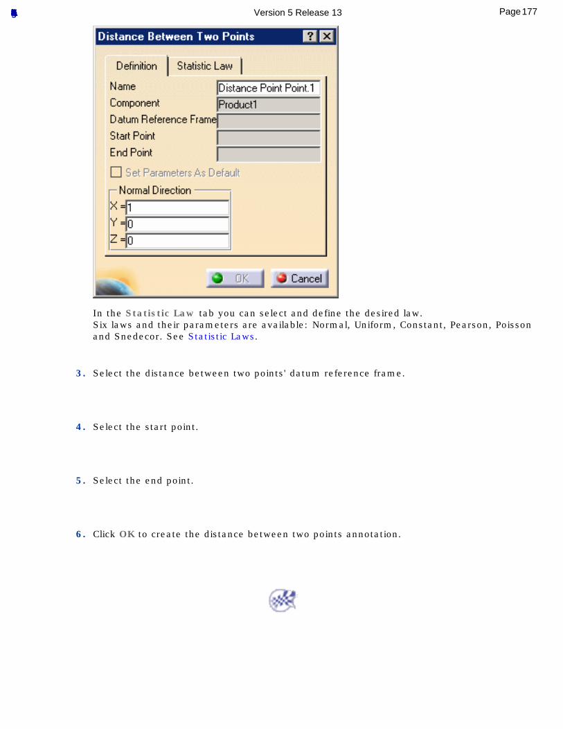
In the Statistic Law tab you can select and define the desired law.Six laws and their parameters are available: Normal, Uniform, Constant, Pearson, Poisson and Snedecor. See Statistic Laws.
3. Select the distance between two points' datum reference frame.
4. Select the start point.
5. Select the end point.
6. Click OK to create the distance between two points annotation.
177Page Functional Tolerancing & Annotation Version 5 Release 13
Managing Annotations
Select Annotation/Annotation Plane: select annotations according of an annotation plane or annotation planes of a set of annotations.
Display Annotation in the Normal View: click this icon and select an annotation.
Move a Textual Annotation: select the annotation and drag it to the desired location, or edit the entry fields from the Orientation and Position toolbar.
Transfer Existing Annotations: select the annotation, right-click to select the Transfer to View/Annotation Plane contextual command and select a new annotation plane.
Transfer Annotations During Creation: select the annotation, right-click to select the Transfer to View/Annotation Plane contextual menu item and select a new annotation plane.
Group Annotations: click the annotation icon you need for creating a new annotation, select the annotation to which you want to attach the new annotation and confirm the creation.
Grouping Annotations Automatically: select a set of annotation and click this icon.
Grouping and Ordering Annotations: click this icon, select the reference annotation, select the reference to be grouped.
Make the Position of a Text Associative: right-click the slave text and select the Annotation Links -> Create Positional Link contextual menu item, then select the master text.
Make the Orientation of a Text Associative: right-click the slave text and select the Annotation Links -> Create Orientation Link contextual menu item, then select the master text.
Mirror Annotations: click this icon, the reversed annotations are mirrored.
Clip Annotations Plane: click this icon, the part is clipped by the annotation plane.
Mark Non-semantic Annotations: select or not the option.
Set Annotation Parallel to Screen: select an annotation and activate this option.
Replace a Datum Reference Frame: select a reference frame annotation and select a new datum.
Use 3D Grid: click this icon and select an annotation.
178Page Functional Tolerancing & Annotation Version 5 Release 13
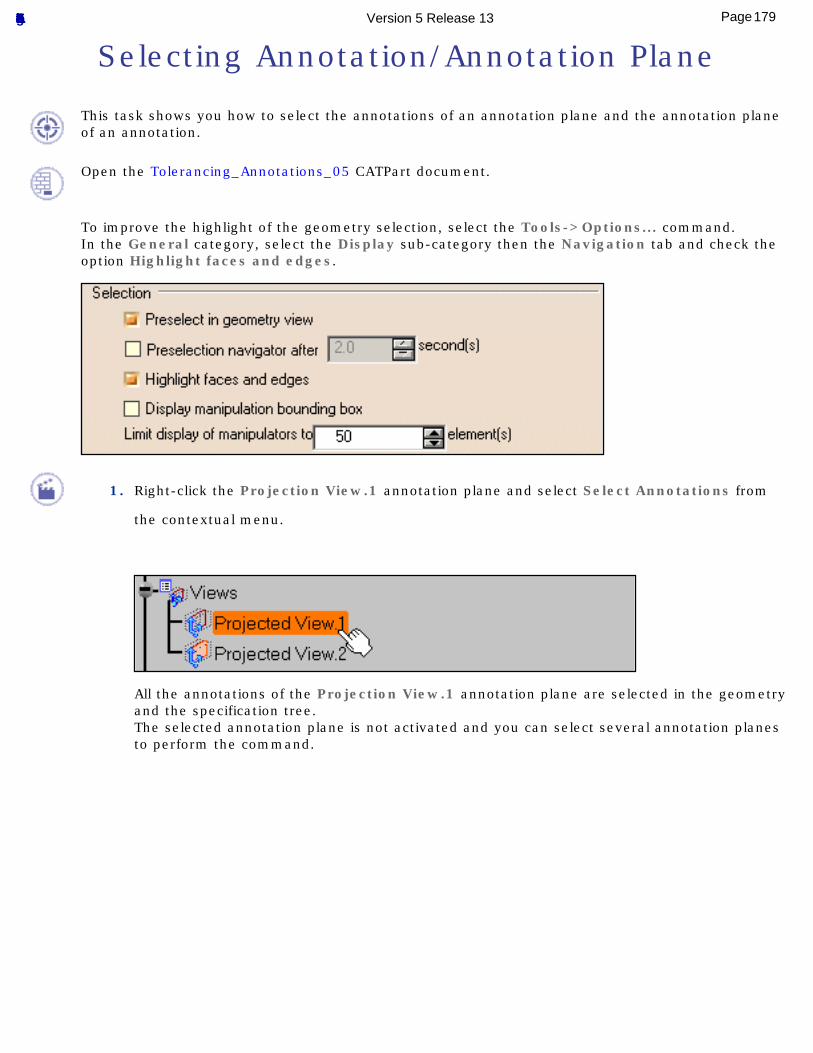
Selecting Annotation/Annotation Plane
This task shows you how to select the annotations of an annotation plane and the annotation plane of an annotation.
Open the Tolerancing_Annotations_05 CATPart document.
To improve the highlight of the geometry selection, select the Tools->Options... command.In the General category, select the Display sub-category then the Navigation tab and check the option Highlight faces and edges.
1. Right-click the Projection View.1 annotation plane and select Select Annotations from
the contextual menu.
All the annotations of the Projection View.1 annotation plane are selected in the geometry and the specification tree.The selected annotation plane is not activated and you can select several annotation planes to perform the command.
179Page Functional Tolerancing & Annotation Version 5 Release 13
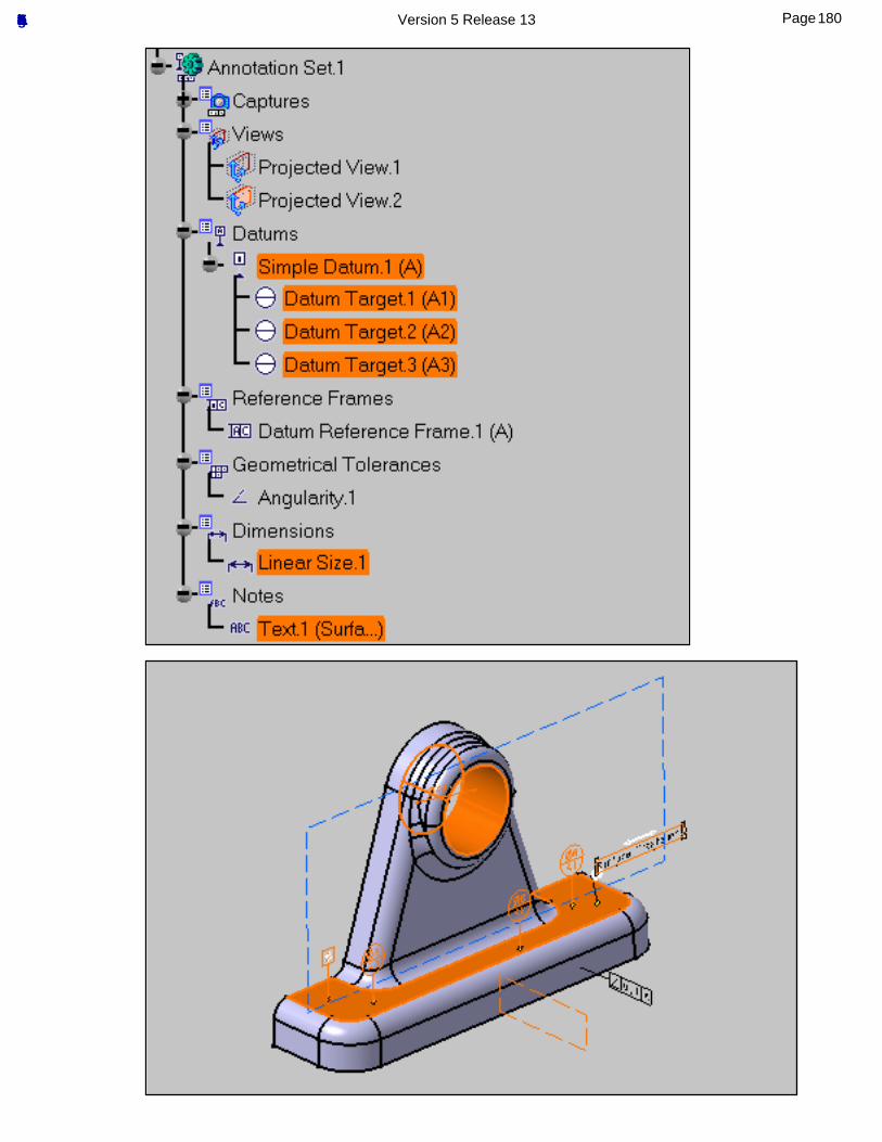
180Page Functional Tolerancing & Annotation Version 5 Release 13
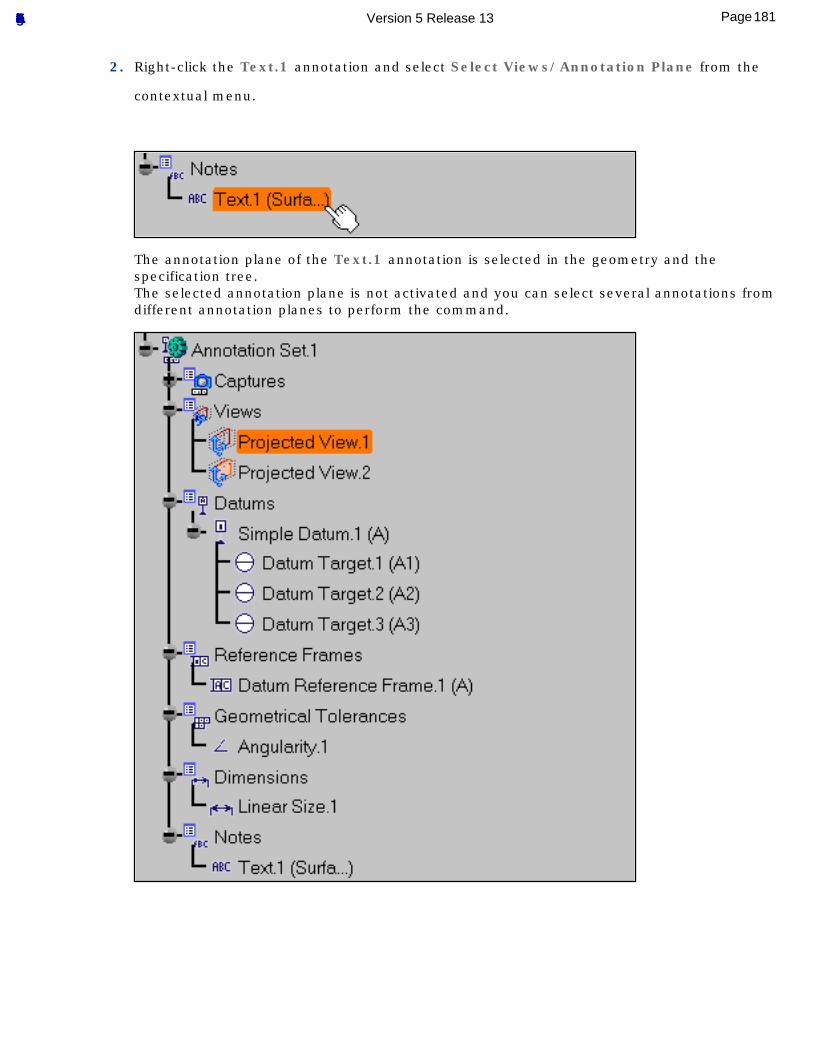
2. Right-click the Text.1 annotation and select Select Views/Annotation Plane from the
contextual menu.
The annotation plane of the Text.1 annotation is selected in the geometry and the specification tree.The selected annotation plane is not activated and you can select several annotations from different annotation planes to perform the command.
181Page Functional Tolerancing & Annotation Version 5 Release 13
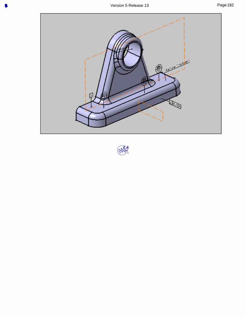
182Page Functional Tolerancing & Annotation Version 5 Release 13
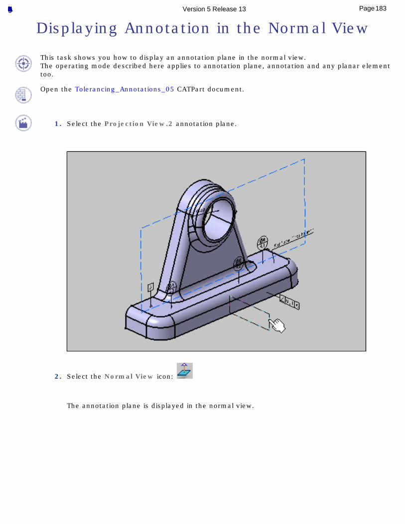
Displaying Annotation in the Normal View
This task shows you how to display an annotation plane in the normal view.The operating mode described here applies to annotation plane, annotation and any planar element too.
Open the Tolerancing_Annotations_05 CATPart document.
1. Select the Projection View.2 annotation plane.
2. Select the Normal View icon:
The annotation plane is displayed in the normal view.
183Page Functional Tolerancing & Annotation Version 5 Release 13
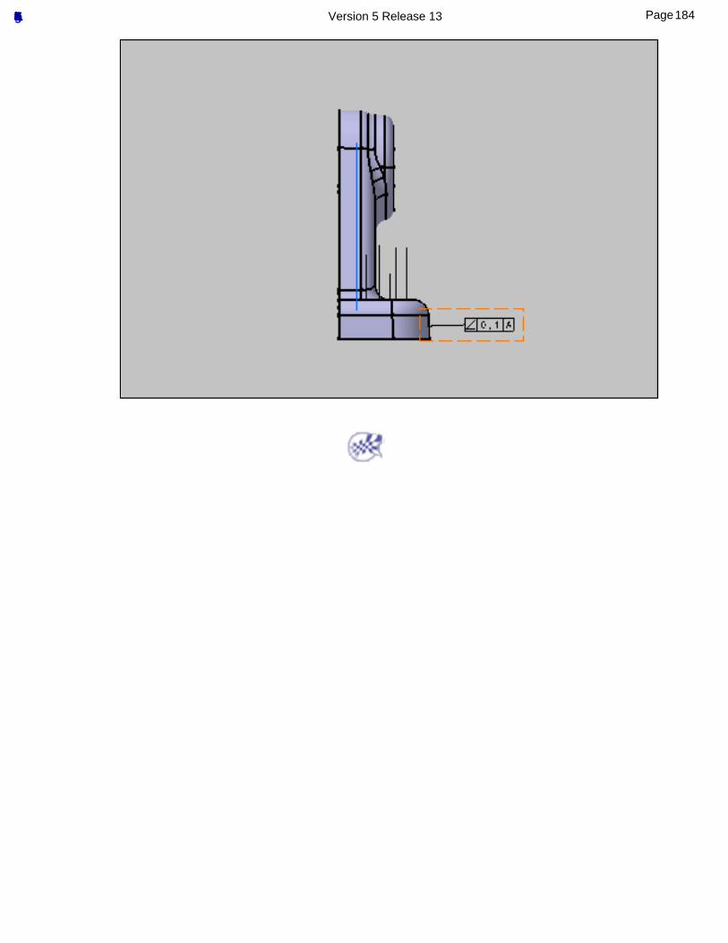
184Page Functional Tolerancing & Annotation Version 5 Release 13
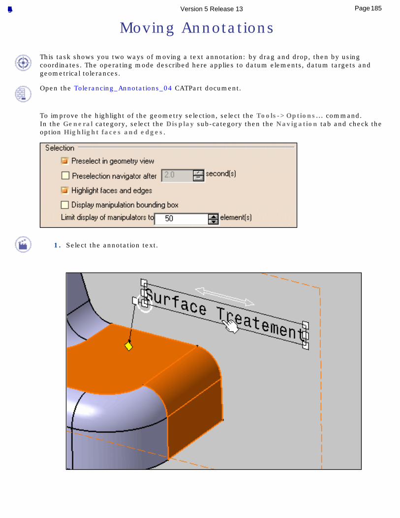
Moving Annotations
This task shows you two ways of moving a text annotation: by drag and drop, then by using coordinates. The operating mode described here applies to datum elements, datum targets and geometrical tolerances.
Open the Tolerancing_Annotations_04 CATPart document.
To improve the highlight of the geometry selection, select the Tools->Options... command.In the General category, select the Display sub-category then the Navigation tab and check the option Highlight faces and edges.
1. Select the annotation text.
185Page Functional Tolerancing & Annotation Version 5 Release 13
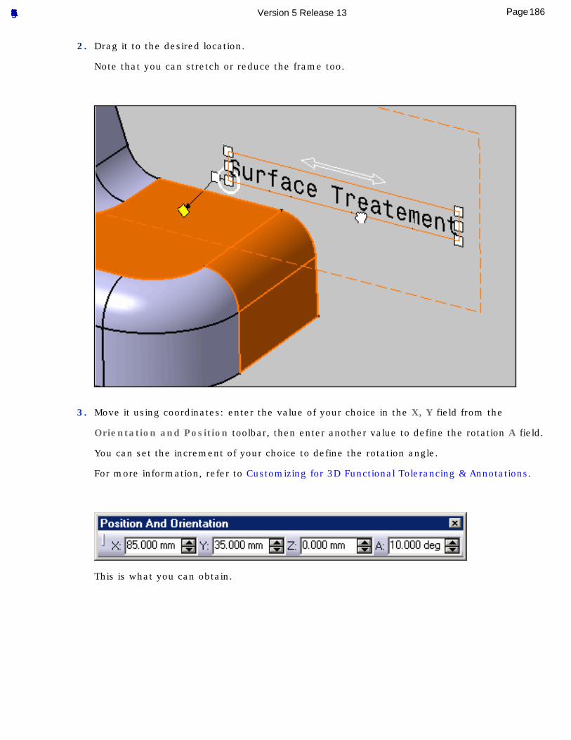
2. Drag it to the desired location.
Note that you can stretch or reduce the frame too.
3. Move it using coordinates: enter the value of your choice in the X, Y field from the
Orientation and Position toolbar, then enter another value to define the rotation A field.
You can set the increment of your choice to define the rotation angle.
For more information, refer to Customizing for 3D Functional Tolerancing & Annotations.
This is what you can obtain.
186Page Functional Tolerancing & Annotation Version 5 Release 13
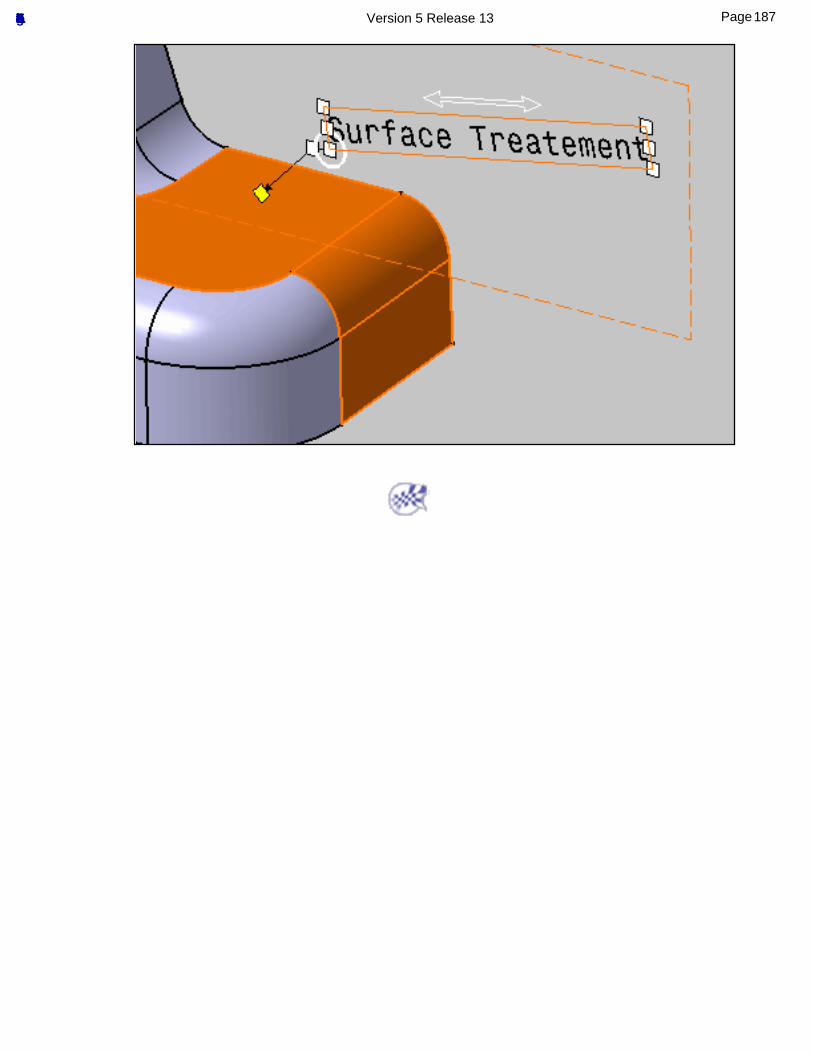
187Page Functional Tolerancing & Annotation Version 5 Release 13
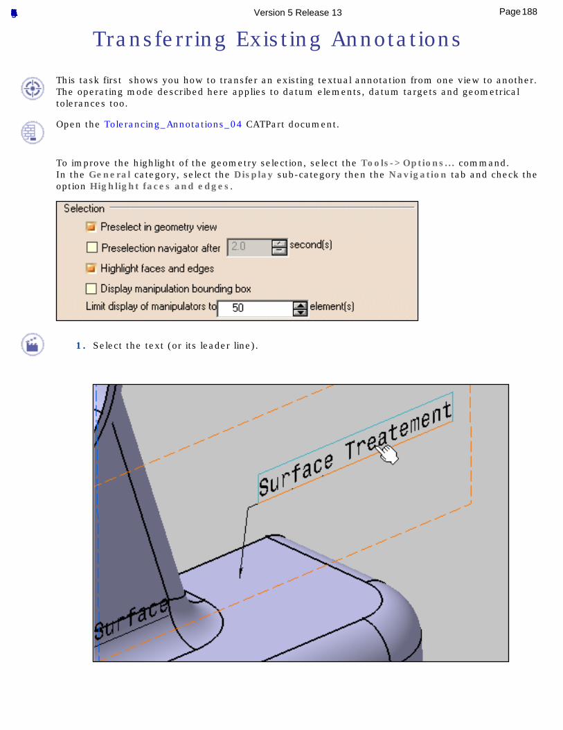
Transferring Existing Annotations
This task first shows you how to transfer an existing textual annotation from one view to another.The operating mode described here applies to datum elements, datum targets and geometrical tolerances too.
Open the Tolerancing_Annotations_04 CATPart document.
To improve the highlight of the geometry selection, select the Tools->Options... command.In the General category, select the Display sub-category then the Navigation tab and check the option Highlight faces and edges.
1. Select the text (or its leader line).
188Page Functional Tolerancing & Annotation Version 5 Release 13
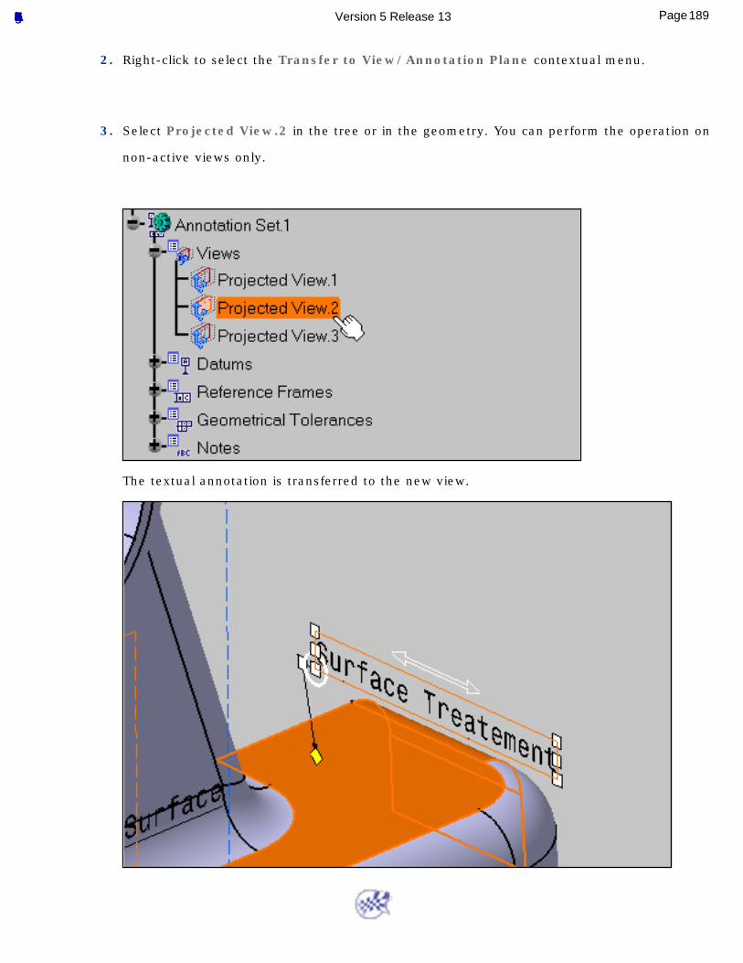
2. Right-click to select the Transfer to View/Annotation Plane contextual menu.
3. Select Projected View.2 in the tree or in the geometry. You can perform the operation on
non-active views only.
The textual annotation is transferred to the new view.
189Page Functional Tolerancing & Annotation Version 5 Release 13
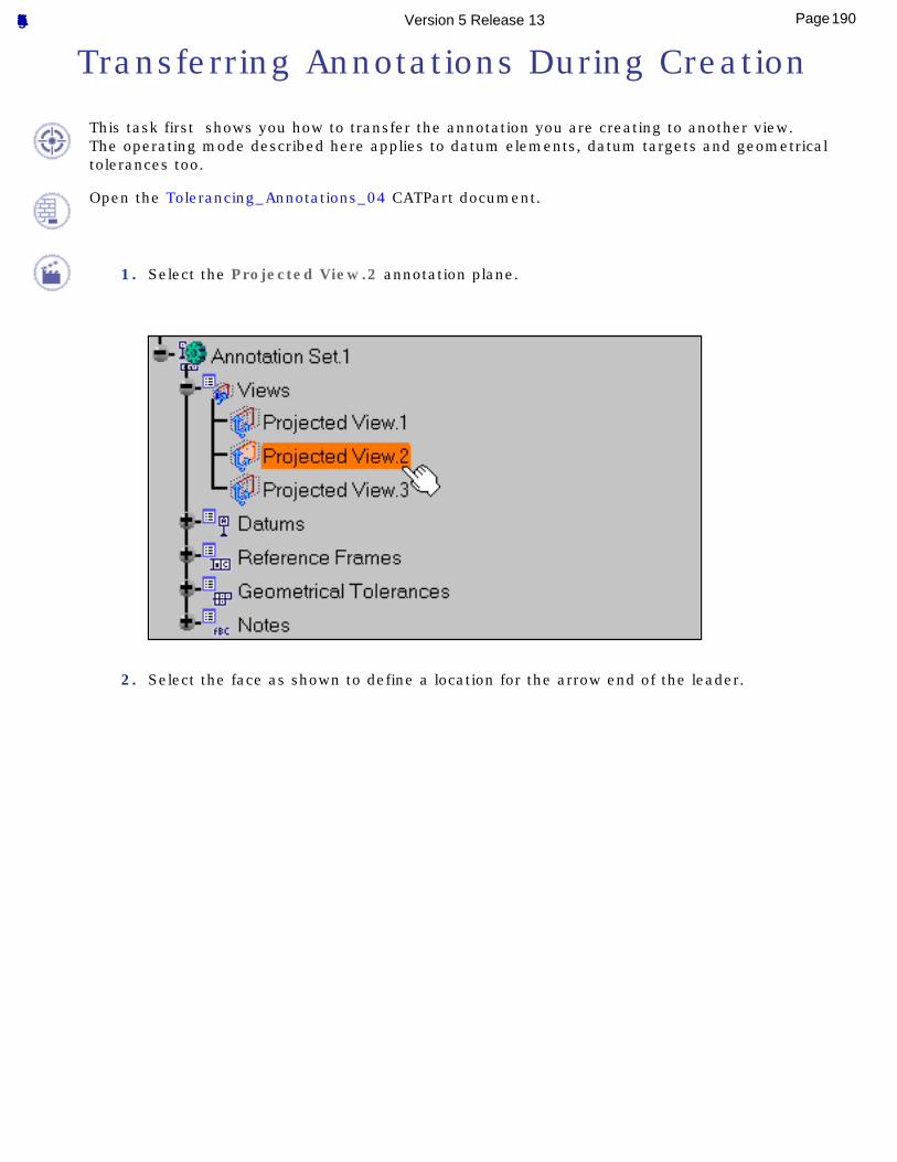
Transferring Annotations During Creation
This task first shows you how to transfer the annotation you are creating to another view.The operating mode described here applies to datum elements, datum targets and geometrical tolerances too.
Open the Tolerancing_Annotations_04 CATPart document.
1. Select the Projected View.2 annotation plane.
2. Select the face as shown to define a location for the arrow end of the leader.
190Page Functional Tolerancing & Annotation Version 5 Release 13
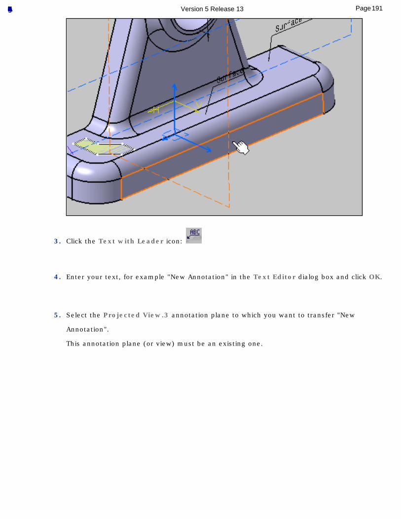
3. Click the Text with Leader icon:
4. Enter your text, for example "New Annotation" in the Text Editor dialog box and click OK.
5. Select the Projected View.3 annotation plane to which you want to transfer "New
Annotation".
This annotation plane (or view) must be an existing one.
191Page Functional Tolerancing & Annotation Version 5 Release 13
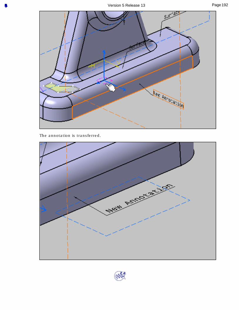
The annotation is transferred.
192Page Functional Tolerancing & Annotation Version 5 Release 13
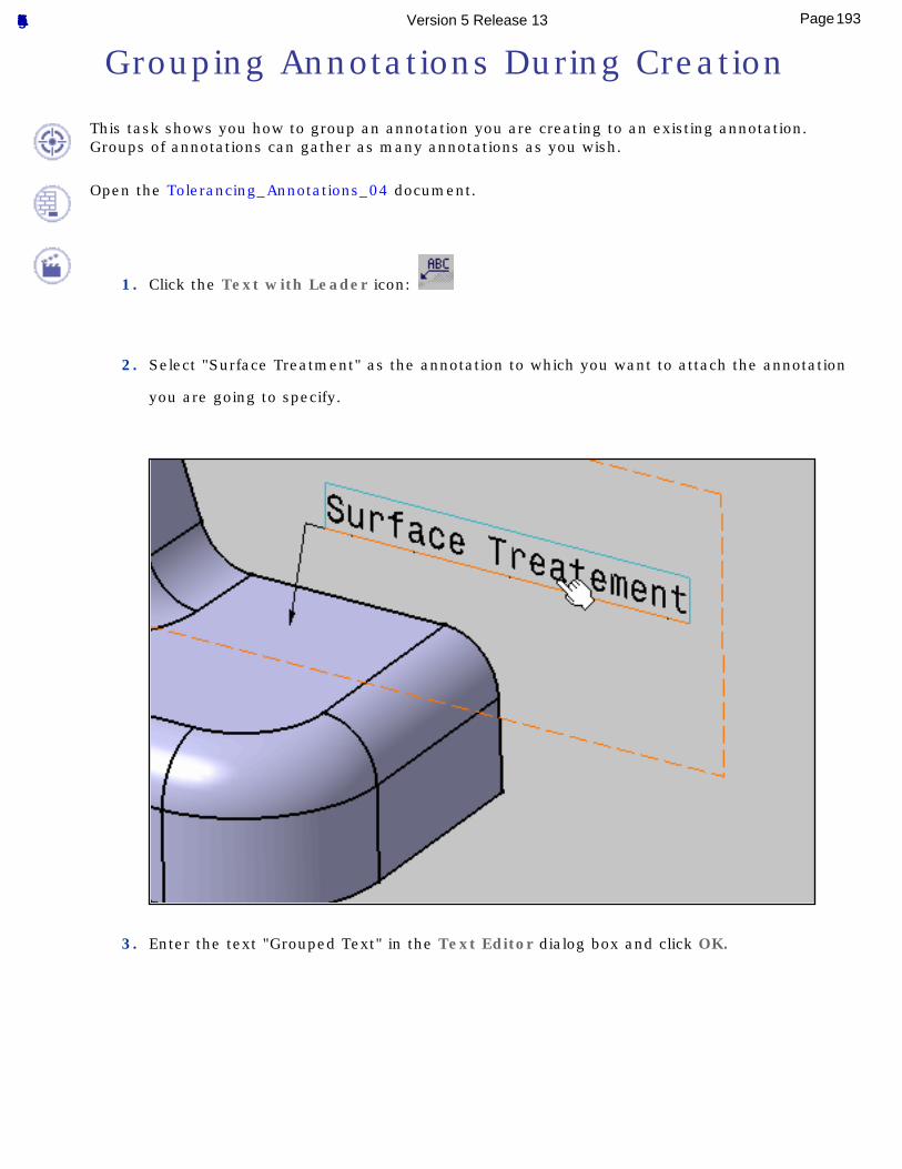
Grouping Annotations During Creation
This task shows you how to group an annotation you are creating to an existing annotation.Groups of annotations can gather as many annotations as you wish.
Open the Tolerancing_Annotations_04 document.
1. Click the Text with Leader icon:
2. Select "Surface Treatment" as the annotation to which you want to attach the annotation
you are going to specify.
3. Enter the text "Grouped Text" in the Text Editor dialog box and click OK.
193Page Functional Tolerancing & Annotation Version 5 Release 13
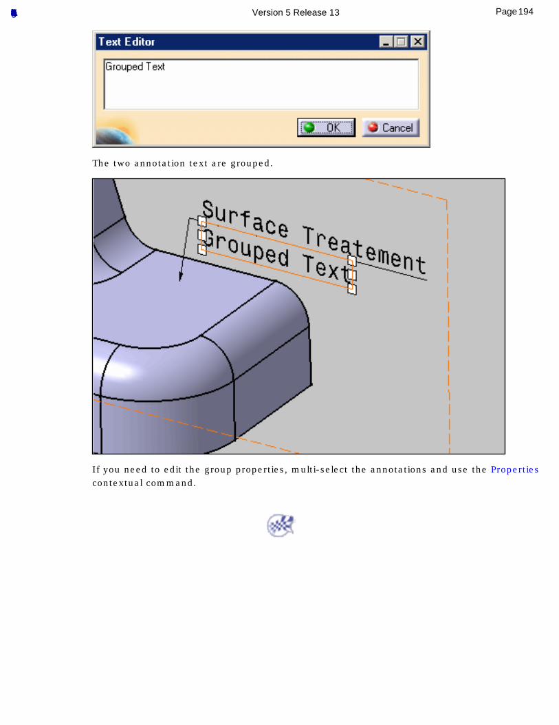
The two annotation text are grouped.
If you need to edit the group properties, multi-select the annotations and use the Properties contextual command.
194Page Functional Tolerancing & Annotation Version 5 Release 13
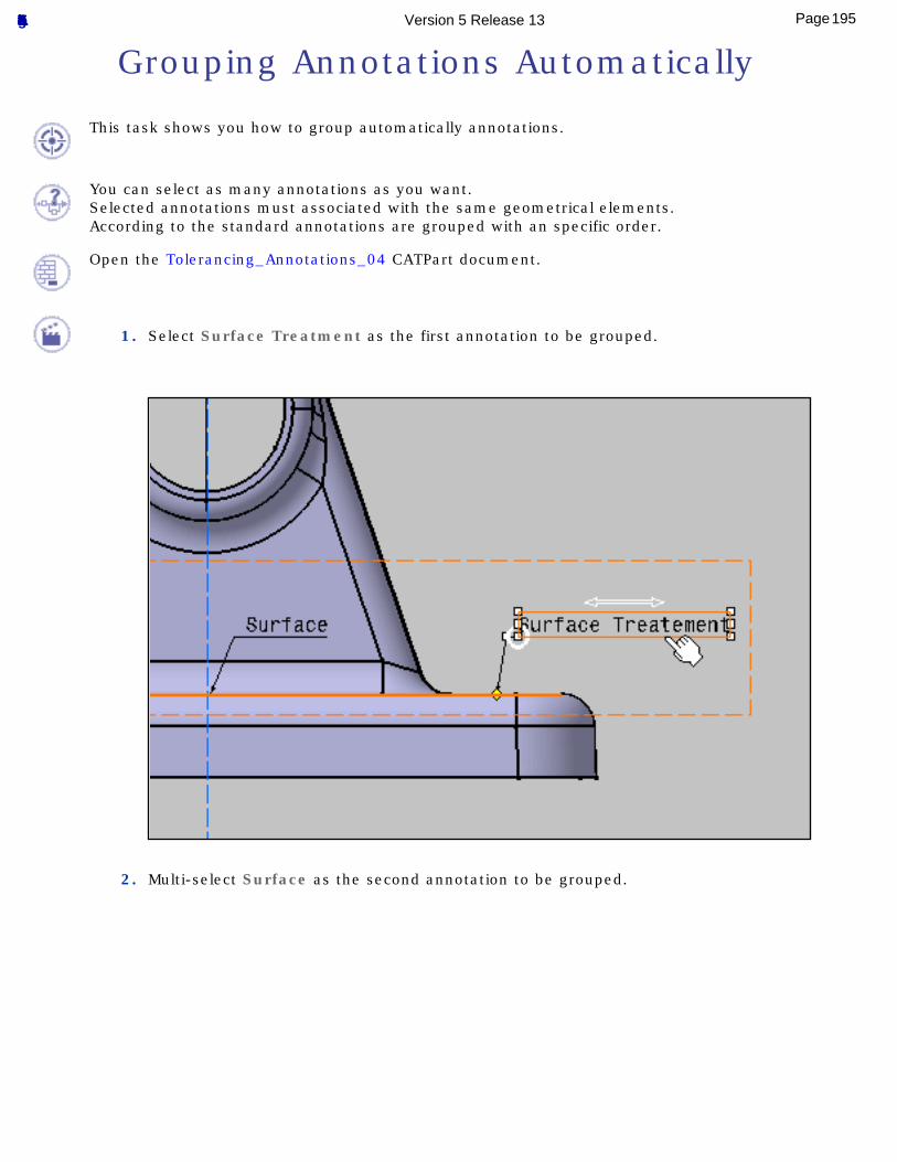
Grouping Annotations Automatically
This task shows you how to group automatically annotations.
You can select as many annotations as you want.Selected annotations must associated with the same geometrical elements.According to the standard annotations are grouped with an specific order.
Open the Tolerancing_Annotations_04 CATPart document.
1. Select Surface Treatment as the first annotation to be grouped.
2. Multi-select Surface as the second annotation to be grouped.
195Page Functional Tolerancing & Annotation Version 5 Release 13
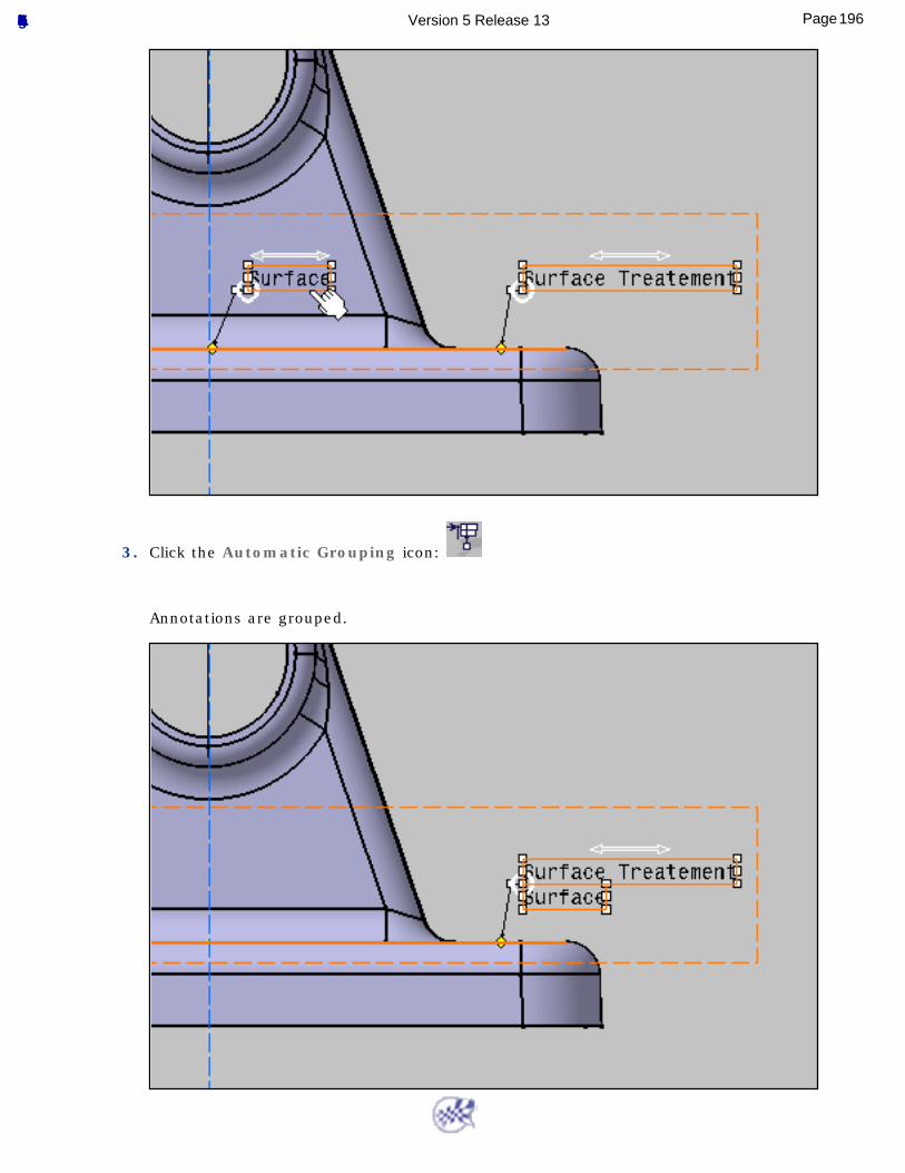
3. Click the Automatic Grouping icon:
Annotations are grouped.
196Page Functional Tolerancing & Annotation Version 5 Release 13
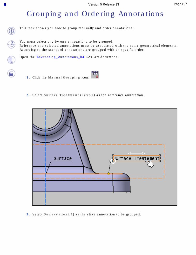
Grouping and Ordering Annotations
This task shows you how to group manually and order annotations.
You must select one by one annotations to be grouped.Reference and selected annotations must be associated with the same geometrical elements.According to the standard annotations are grouped with an specific order.
Open the Tolerancing_Annotations_04 CATPart document.
1. Click the Manual Grouping icon:
2. Select Surface Treatment (Text.1) as the reference annotation.
3. Select Surface (Text.2) as the slave annotation to be grouped.
197Page Functional Tolerancing & Annotation Version 5 Release 13
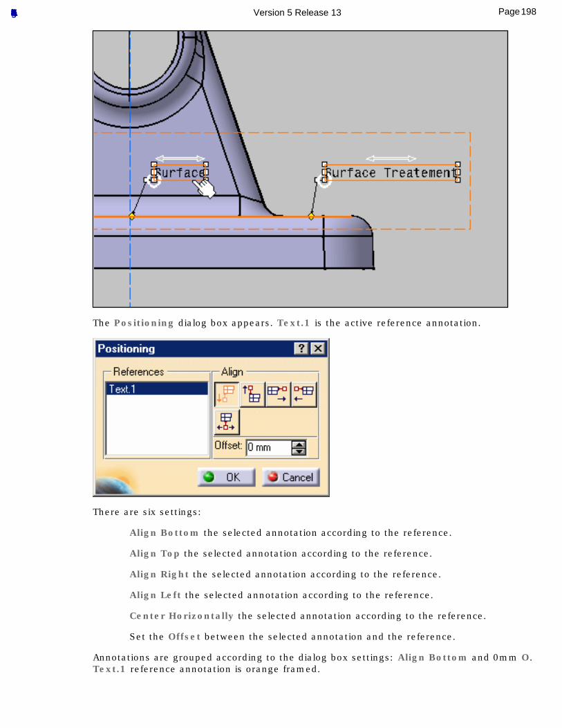
The Positioning dialog box appears. Text.1 is the active reference annotation.
There are six settings:
Align Bottom the selected annotation according to the reference.
Align Top the selected annotation according to the reference.
Align Right the selected annotation according to the reference.
Align Left the selected annotation according to the reference.
Center Horizontally the selected annotation according to the reference.
Set the Offset between the selected annotation and the reference.
Annotations are grouped according to the dialog box settings: Align Bottom and 0mm O.Text.1 reference annotation is orange framed.
198Page Functional Tolerancing & Annotation Version 5 Release 13
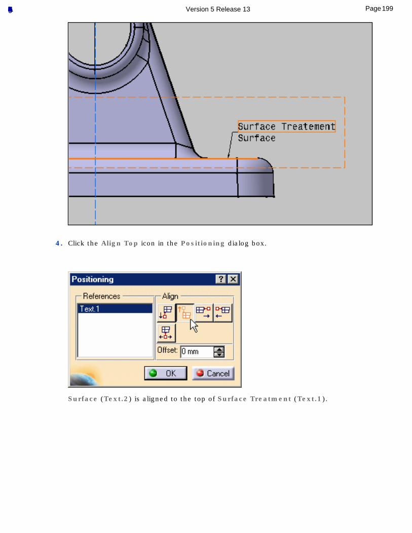
4. Click the Align Top icon in the Positioning dialog box.
Surface (Text.2) is aligned to the top of Surface Treatment (Text.1).
199Page Functional Tolerancing & Annotation Version 5 Release 13
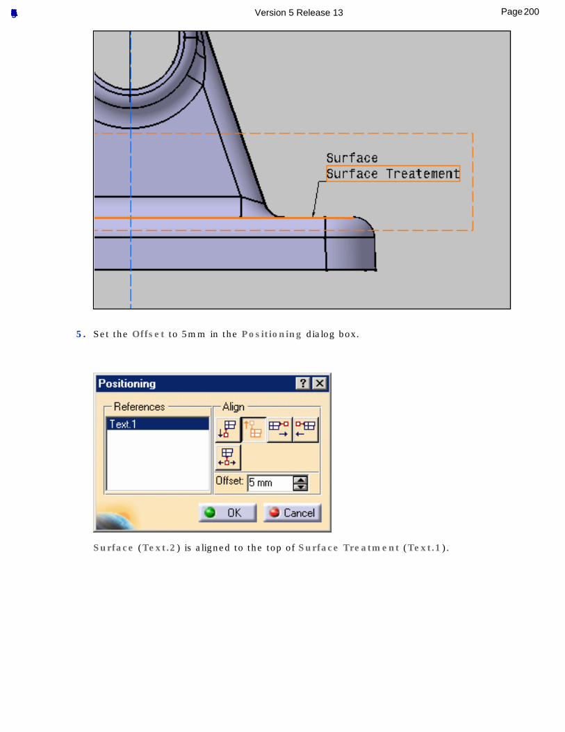
5. Set the Offset to 5mm in the Positioning dialog box.
Surface (Text.2) is aligned to the top of Surface Treatment (Text.1).
200Page Functional Tolerancing & Annotation Version 5 Release 13
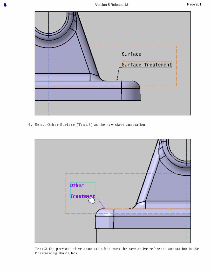
6. Select Other Surface (Text.3) as the new slave annotation.
Text.2 the previous slave annotation becomes the new active reference annotation in the Positioning dialog box.
201Page Functional Tolerancing & Annotation Version 5 Release 13
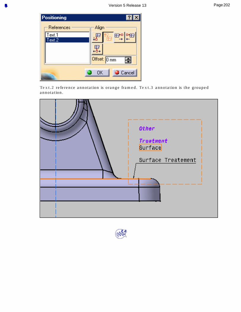
Text.2 reference annotation is orange framed. Text.3 annotation is the grouped annotation.
202Page Functional Tolerancing & Annotation Version 5 Release 13
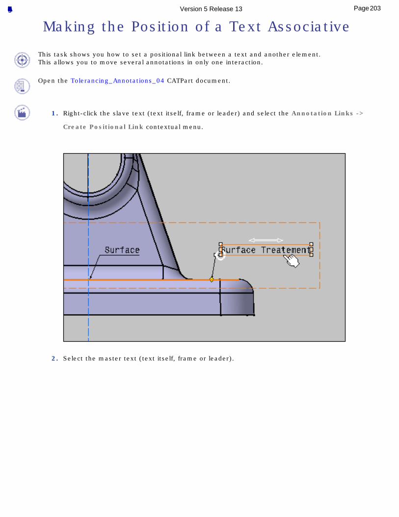
Making the Position of a Text Associative
This task shows you how to set a positional link between a text and another element.This allows you to move several annotations in only one interaction.
Open the Tolerancing_Annotations_04 CATPart document.
1. Right-click the slave text (text itself, frame or leader) and select the Annotation Links ->
Create Positional Link contextual menu.
2. Select the master text (text itself, frame or leader).
203Page Functional Tolerancing & Annotation Version 5 Release 13
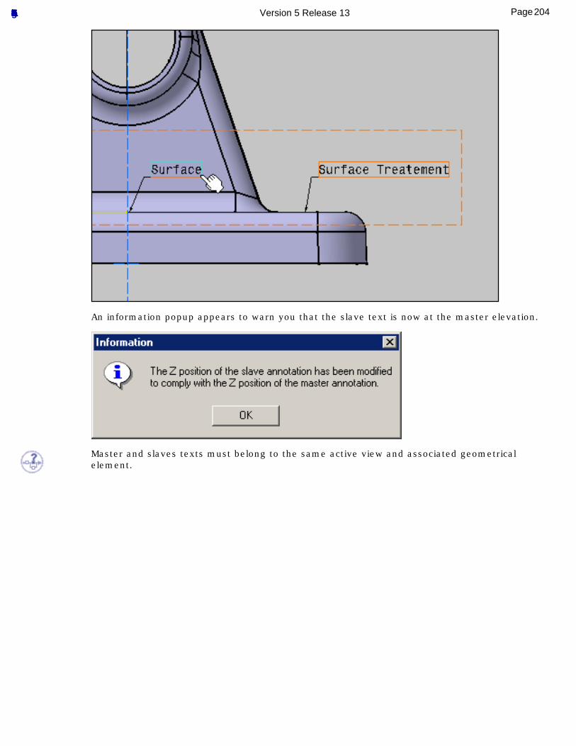
An information popup appears to warn you that the slave text is now at the master elevation.
Master and slaves texts must belong to the same active view and associated geometrical element.
204Page Functional Tolerancing & Annotation Version 5 Release 13
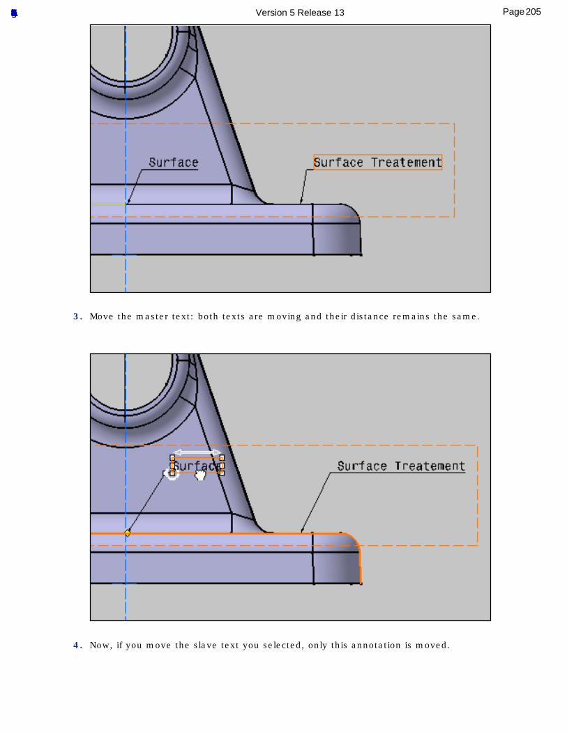
3. Move the master text: both texts are moving and their distance remains the same.
4. Now, if you move the slave text you selected, only this annotation is moved.
205Page Functional Tolerancing & Annotation Version 5 Release 13
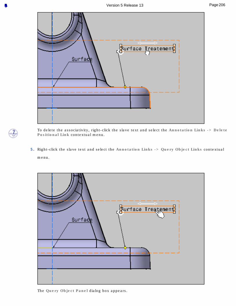
To delete the associativity, right-click the slave text and select the Annotation Links -> Delete Positional Link contextual menu.
5. Right-click the slave text and select the Annotation Links -> Query Object Links contextual
menu.
The Query Object Panel dialog box appears.
206Page Functional Tolerancing & Annotation Version 5 Release 13
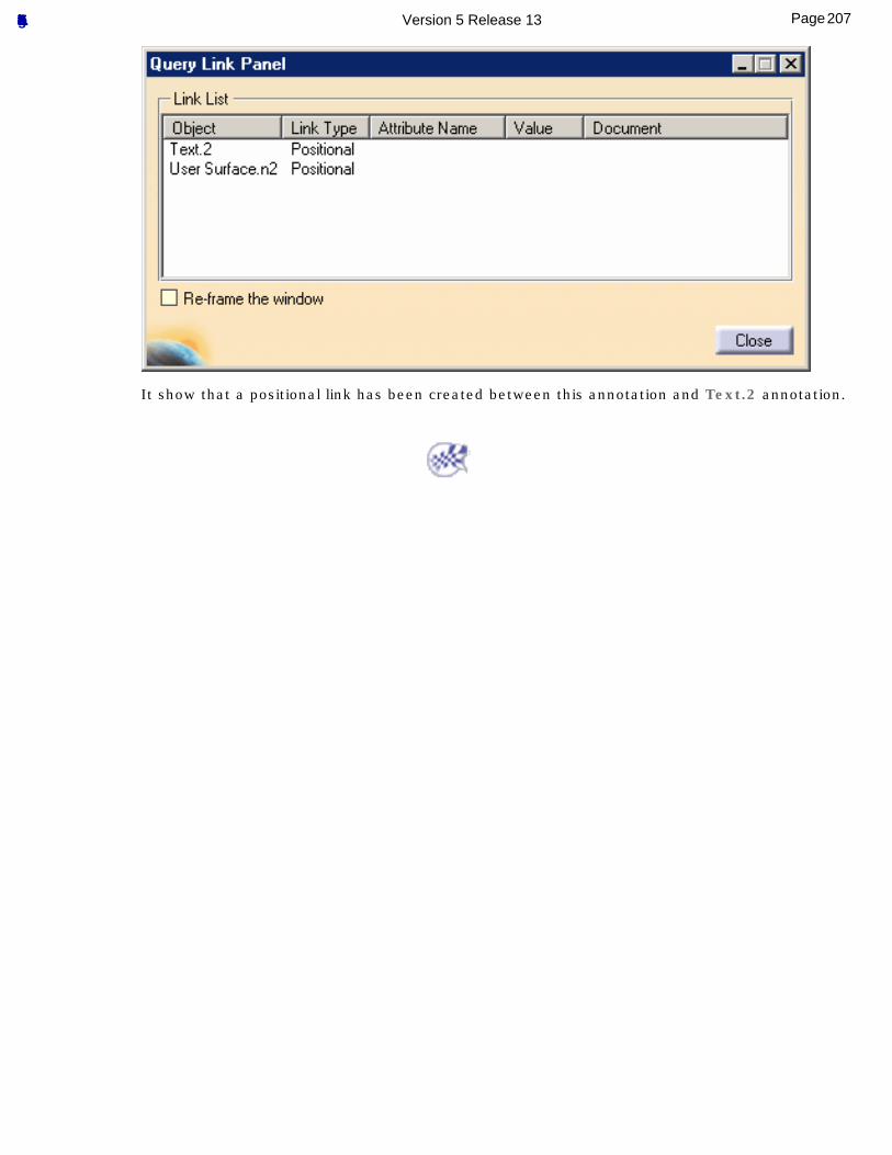
It show that a positional link has been created between this annotation and Text.2 annotation.
207Page Functional Tolerancing & Annotation Version 5 Release 13
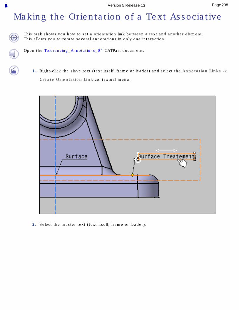
Making the Orientation of a Text Associative
This task shows you how to set a orientation link between a text and another element.This allows you to rotate several annotations in only one interaction.
Open the Tolerancing_Annotations_04 CATPart document.
1. Right-click the slave text (text itself, frame or leader) and select the Annotation Links ->
Create Orientation Link contextual menu.
2. Select the master text (text itself, frame or leader).
208Page Functional Tolerancing & Annotation Version 5 Release 13
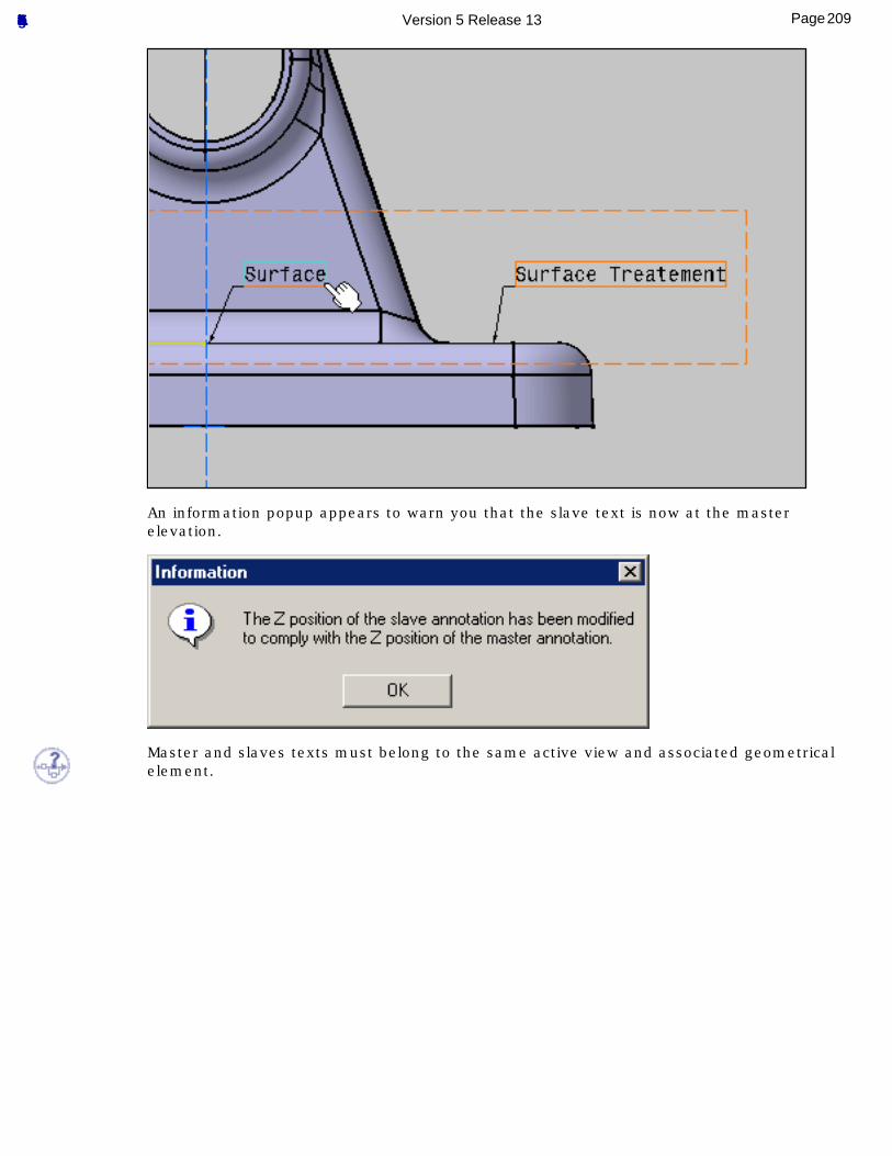
An information popup appears to warn you that the slave text is now at the master elevation.
Master and slaves texts must belong to the same active view and associated geometrical element.
209Page Functional Tolerancing & Annotation Version 5 Release 13
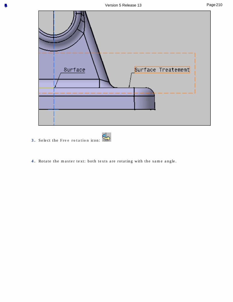
3. Select the Free rotation icon:
4. Rotate the master text: both texts are rotating with the same angle.
210Page Functional Tolerancing & Annotation Version 5 Release 13
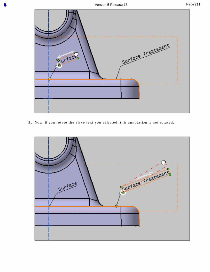
5. Now, if you rotate the slave text you selected, this annotation is not rotated.
211Page Functional Tolerancing & Annotation Version 5 Release 13
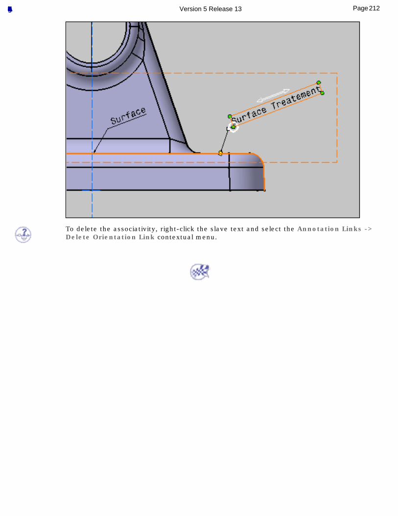
To delete the associativity, right-click the slave text and select the Annotation Links -> Delete Orientation Link contextual menu.
212Page Functional Tolerancing & Annotation Version 5 Release 13
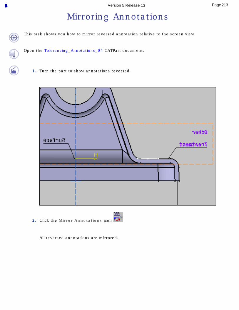
Mirroring Annotations
This task shows you how to mirror reversed annotation relative to the screen view.
Open the Tolerancing_Annotations_04 CATPart document.
1. Turn the part to show annotations reversed.
2. Click the Mirror Annotations icon
All reversed annotations are mirrored.
213Page Functional Tolerancing & Annotation Version 5 Release 13
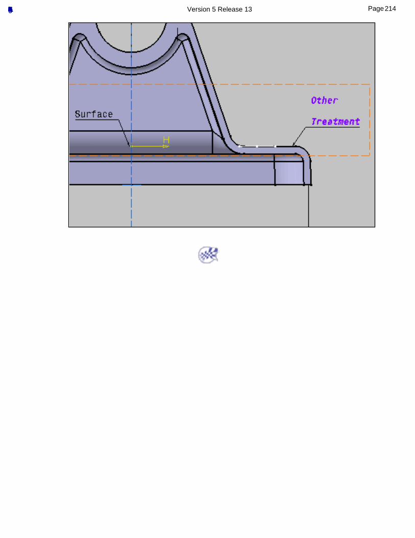
214Page Functional Tolerancing & Annotation Version 5 Release 13
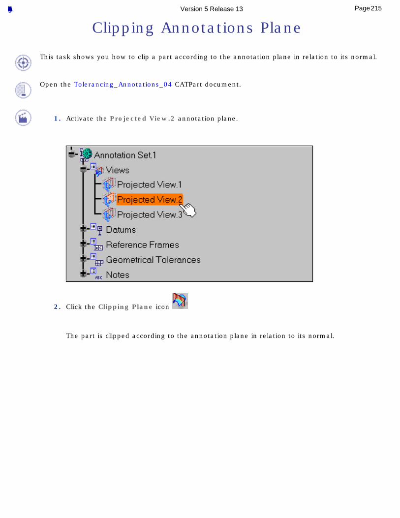
Clipping Annotations Plane
This task shows you how to clip a part according to the annotation plane in relation to its normal.
Open the Tolerancing_Annotations_04 CATPart document.
1. Activate the Projected View.2 annotation plane.
2. Click the Clipping Plane icon
The part is clipped according to the annotation plane in relation to its normal.
215Page Functional Tolerancing & Annotation Version 5 Release 13
216Page Functional Tolerancing & Annotation Version 5 Release 13
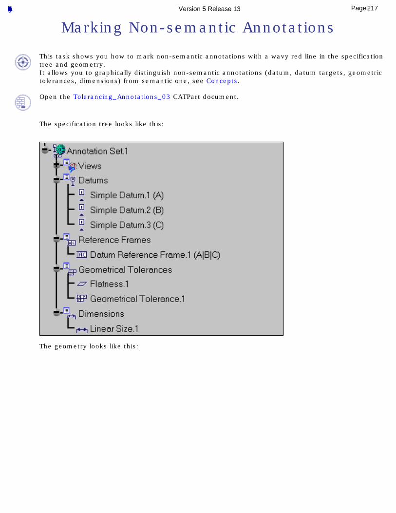
Marking Non-semantic Annotations
This task shows you how to mark non-semantic annotations with a wavy red line in the specification tree and geometry.It allows you to graphically distinguish non-semantic annotations (datum, datum targets, geometric tolerances, dimensions) from semantic one, see Concepts.
Open the Tolerancing_Annotations_03 CATPart document.
The specification tree looks like this:
The geometry looks like this:
217Page Functional Tolerancing & Annotation Version 5 Release 13
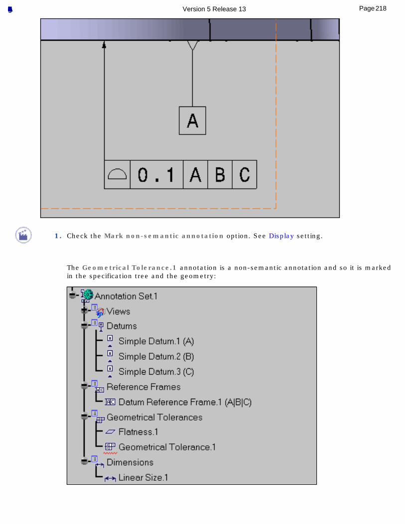
1. Check the Mark non-semantic annotation option. See Display setting.
The Geometrical Tolerance.1 annotation is a non-semantic annotation and so it is marked in the specification tree and the geometry:
218Page Functional Tolerancing & Annotation Version 5 Release 13
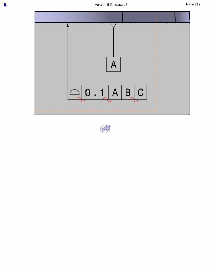
219Page Functional Tolerancing & Annotation Version 5 Release 13
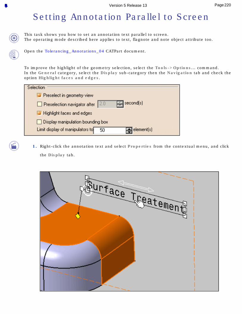
Setting Annotation Parallel to Screen
This task shows you how to set an annotation text parallel to screen.The operating mode described here applies to text, flagnote and note object attribute too.
Open the Tolerancing_Annotations_04 CATPart document.
To improve the highlight of the geometry selection, select the Tools->Options... command.In the General category, select the Display sub-category then the Navigation tab and check the option Highlight faces and edges.
1. Right-click the annotation text and select Properties from the contextual menu, and click
the Display tab.
220Page Functional Tolerancing & Annotation Version 5 Release 13
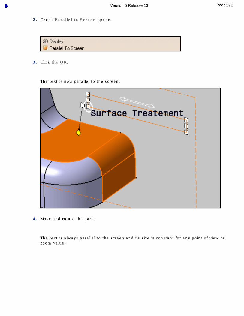
2. Check Parallel to Screen option.
3. Click the OK.
The text is now parallel to the screen.
4. Move and rotate the part..
The text is always parallel to the screen and its size is constant for any point of view or zoom value.
221Page Functional Tolerancing & Annotation Version 5 Release 13
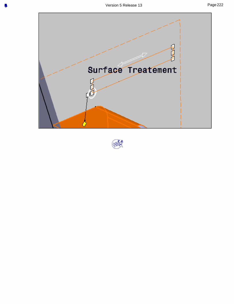
222Page Functional Tolerancing & Annotation Version 5 Release 13
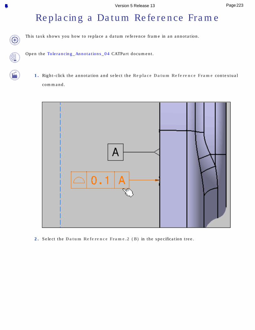
Replacing a Datum Reference Frame
This task shows you how to replace a datum reference frame in an annotation.
Open the Tolerancing_Annotations_04 CATPart document.
1. Right-click the annotation and select the Replace Datum Reference Frame contextual
command.
2. Select the Datum Reference Frame.2 (B) in the specification tree.
223Page Functional Tolerancing & Annotation Version 5 Release 13
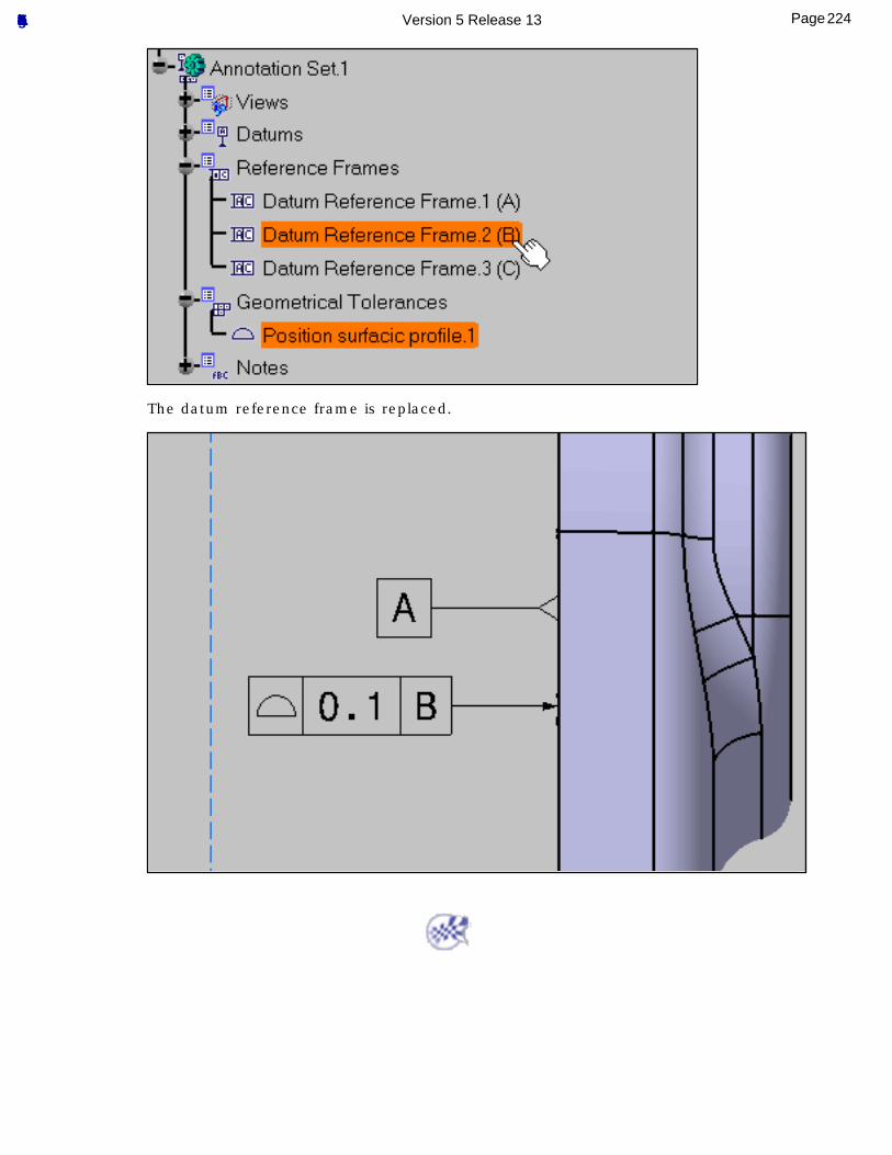
The datum reference frame is replaced.
224Page Functional Tolerancing & Annotation Version 5 Release 13
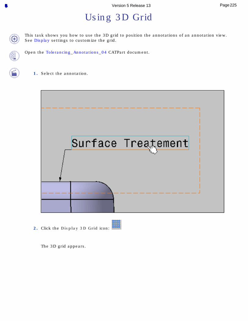
Using 3D Grid
This task shows you how to use the 3D grid to position the annotations of an annotation view.See Display settings to customize the grid.
Open the Tolerancing_Annotations_04 CATPart document.
1. Select the annotation.
2. Click the Display 3D Grid icon:
The 3D grid appears.
225Page Functional Tolerancing & Annotation Version 5 Release 13
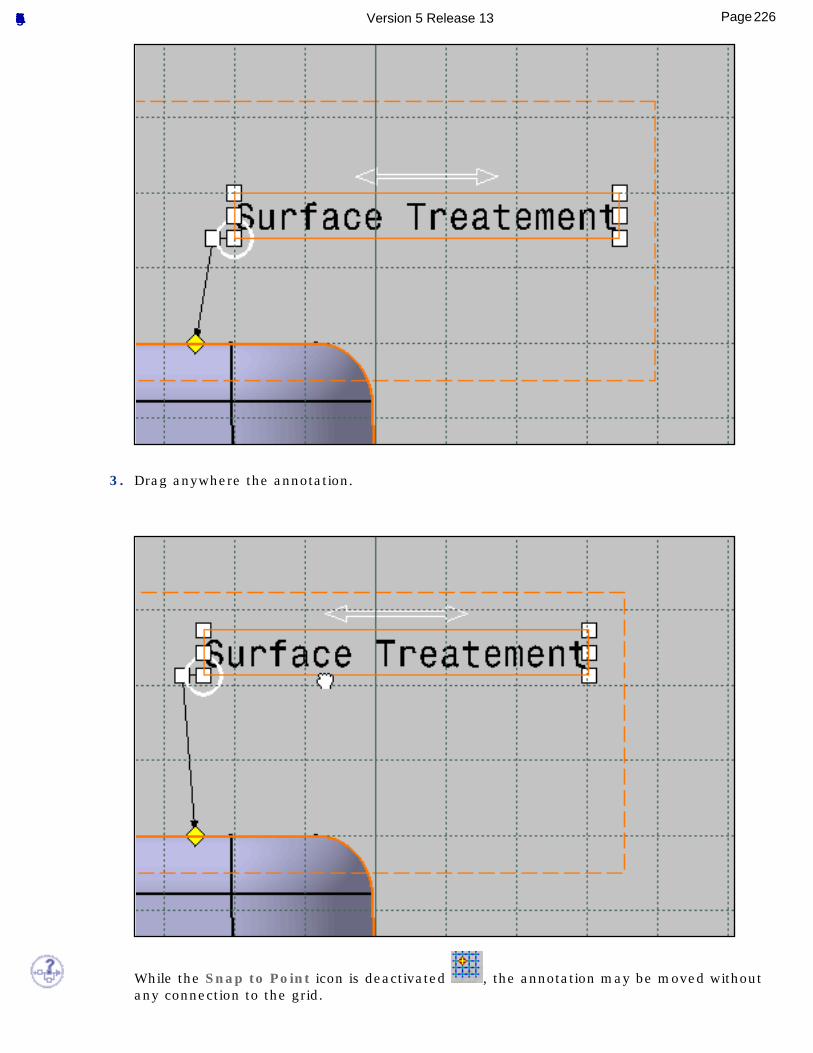
3. Drag anywhere the annotation.
While the Snap to Point icon is deactivated , the annotation may be moved without any connection to the grid.
226Page Functional Tolerancing & Annotation Version 5 Release 13
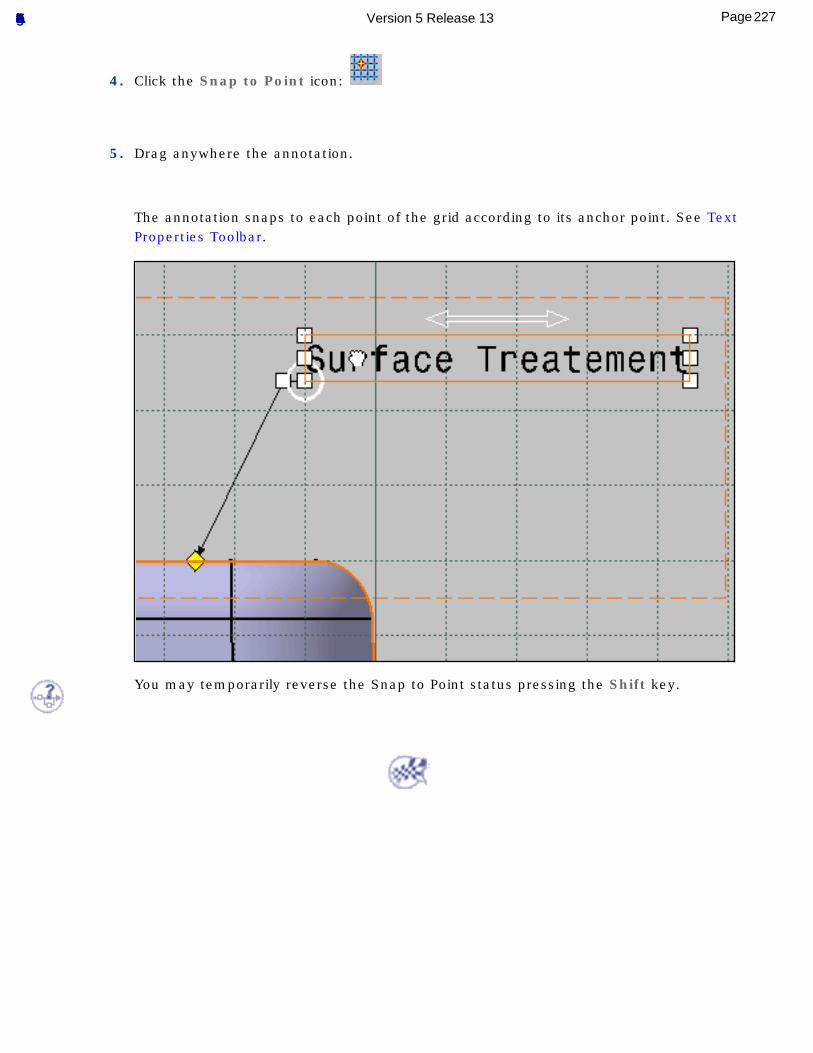
4. Click the Snap to Point icon:
5. Drag anywhere the annotation.
The annotation snaps to each point of the grid according to its anchor point. See Text Properties Toolbar.
You may temporarily reverse the Snap to Point status pressing the Shift key.
227Page Functional Tolerancing & Annotation Version 5 Release 13
Managing Annotation Leaders
Adding Leaders and Using Breakpoint
Editing the Shape of an End Manipulator
Moving the End Manipulator of a Leader
Adding the All Around Symbol
Setting Perpendicular a Leader
Adding an Interruption Leader
228Page Functional Tolerancing & Annotation Version 5 Release 13
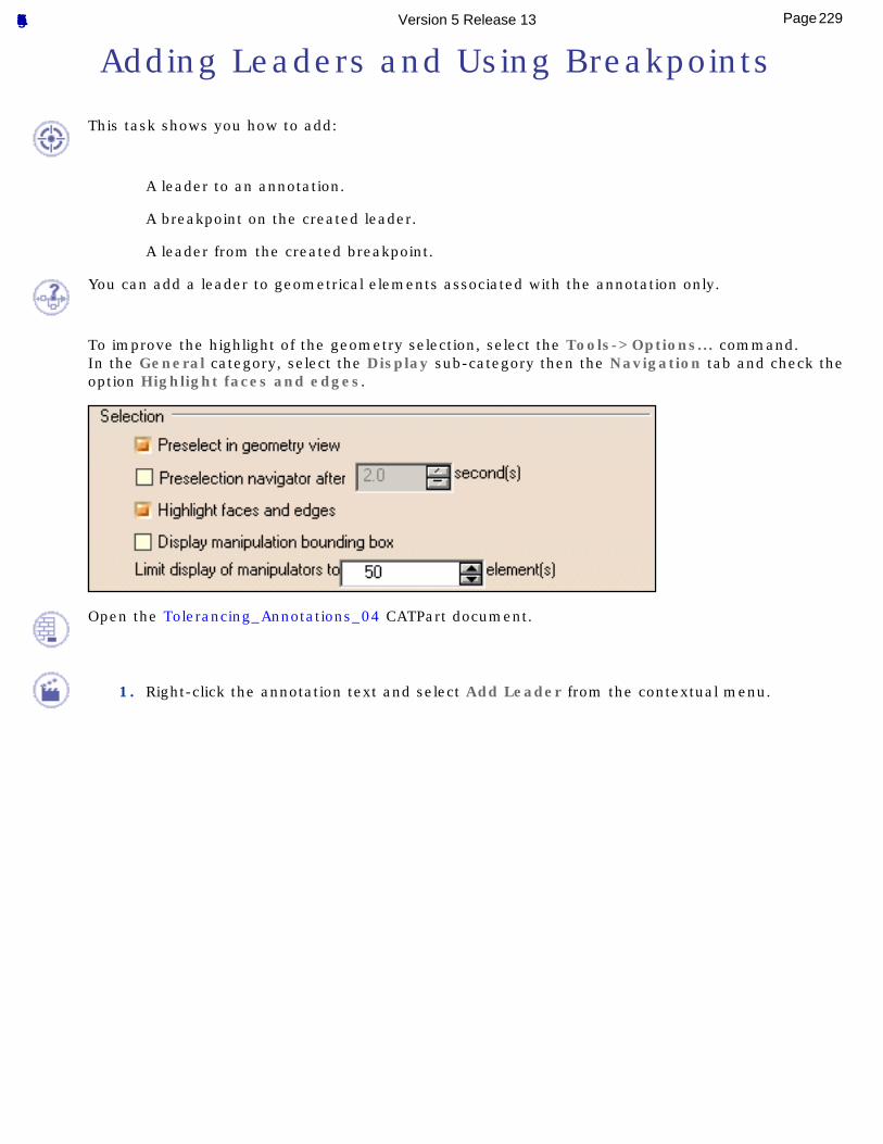
Adding Leaders and Using Breakpoints
This task shows you how to add:
A leader to an annotation.
A breakpoint on the created leader.
A leader from the created breakpoint.
You can add a leader to geometrical elements associated with the annotation only.
To improve the highlight of the geometry selection, select the Tools->Options... command.In the General category, select the Display sub-category then the Navigation tab and check the option Highlight faces and edges.
Open the Tolerancing_Annotations_04 CATPart document.
1. Right-click the annotation text and select Add Leader from the contextual menu.
229Page Functional Tolerancing & Annotation Version 5 Release 13
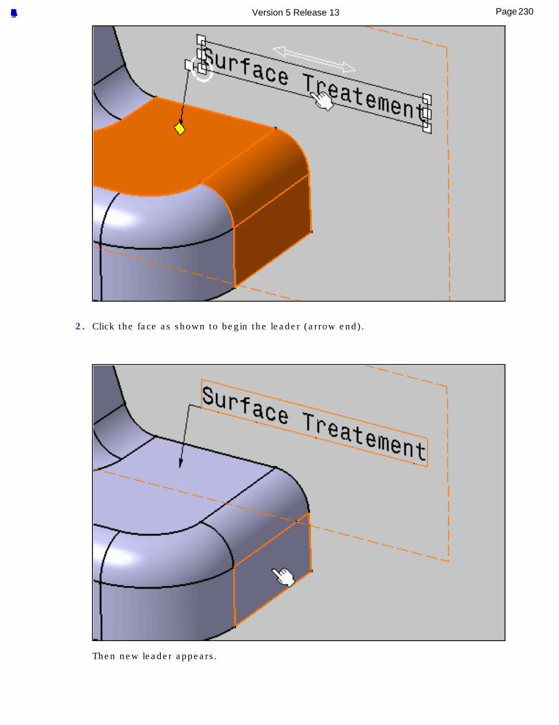
2. Click the face as shown to begin the leader (arrow end).
Then new leader appears.
230Page Functional Tolerancing & Annotation Version 5 Release 13
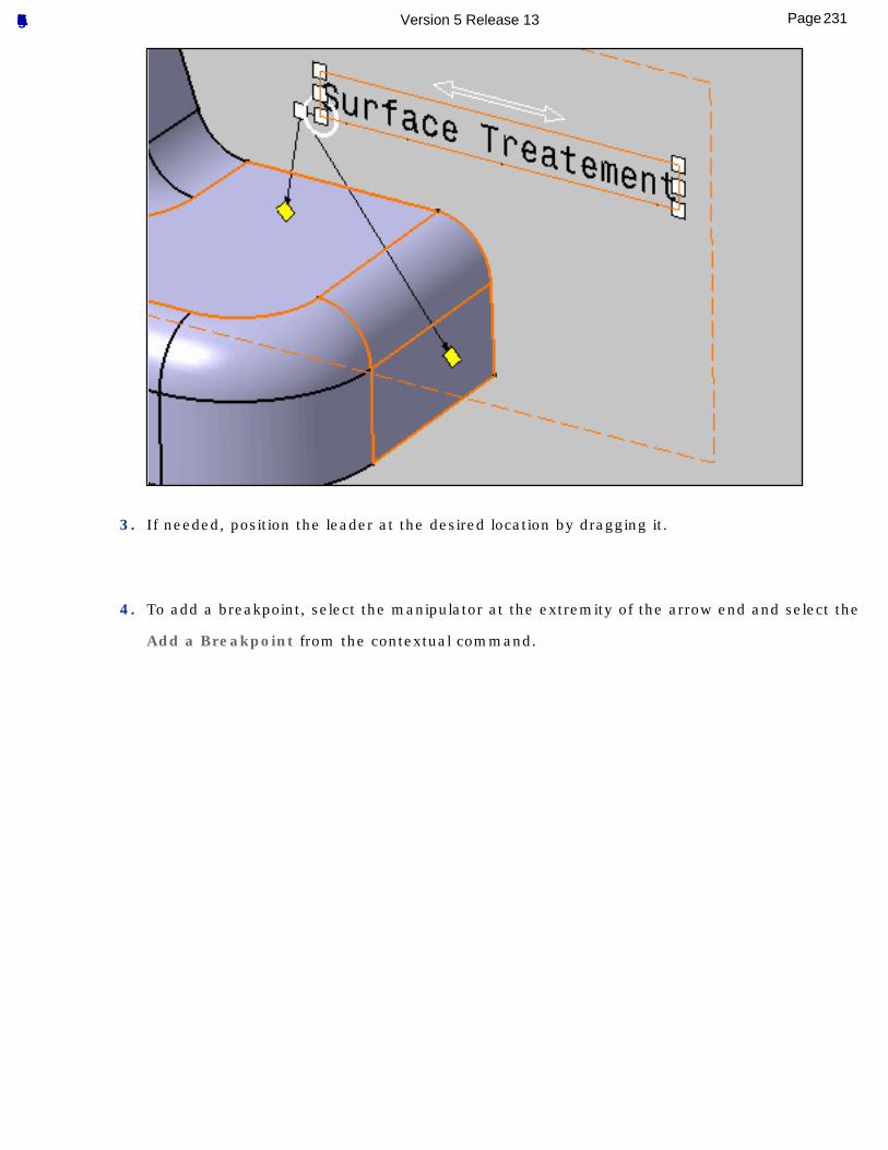
3. If needed, position the leader at the desired location by dragging it.
4. To add a breakpoint, select the manipulator at the extremity of the arrow end and select the
Add a Breakpoint from the contextual command.
231Page Functional Tolerancing & Annotation Version 5 Release 13
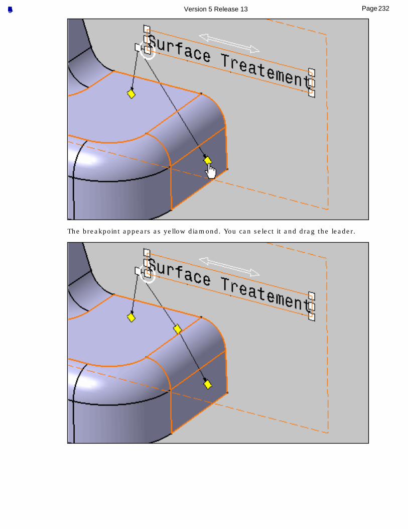
The breakpoint appears as yellow diamond. You can select it and drag the leader.
232Page Functional Tolerancing & Annotation Version 5 Release 13
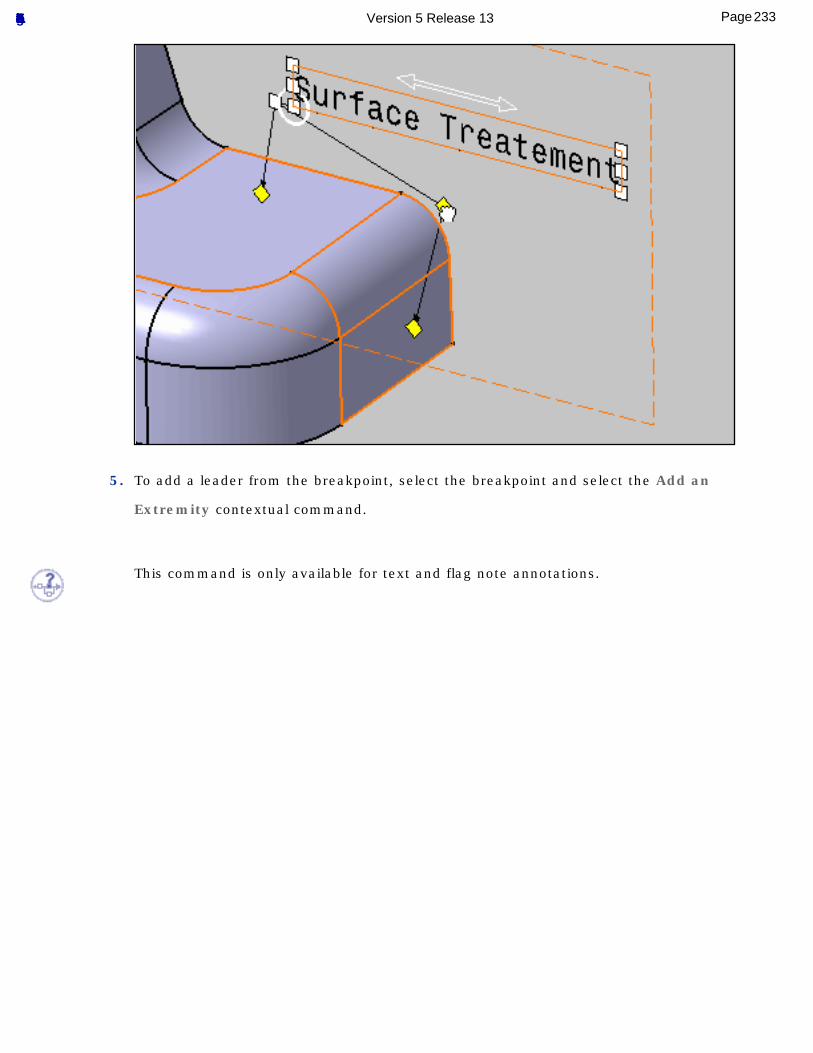
5. To add a leader from the breakpoint, select the breakpoint and select the Add an
Extremity contextual command.
This command is only available for text and flag note annotations.
233Page Functional Tolerancing & Annotation Version 5 Release 13
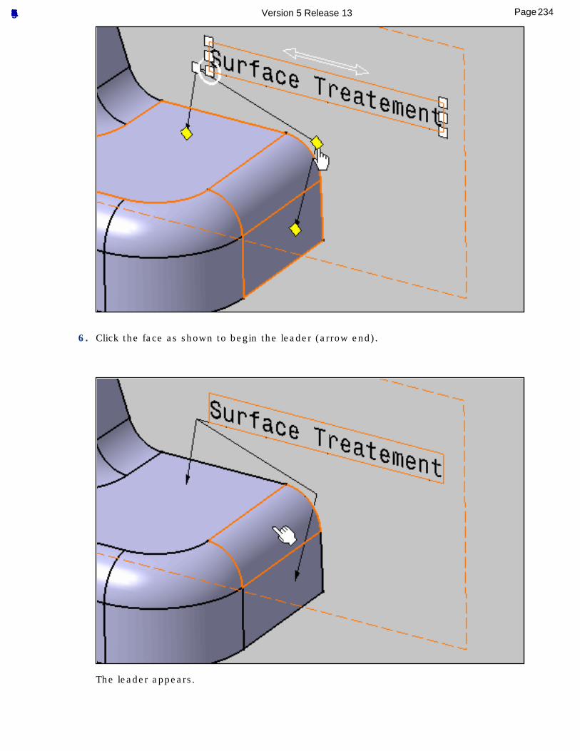
6. Click the face as shown to begin the leader (arrow end).
The leader appears.
234Page Functional Tolerancing & Annotation Version 5 Release 13
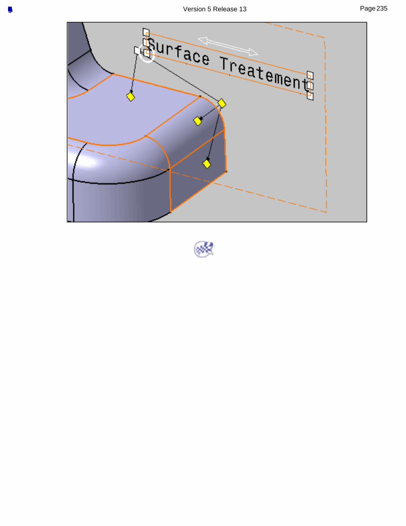
235Page Functional Tolerancing & Annotation Version 5 Release 13
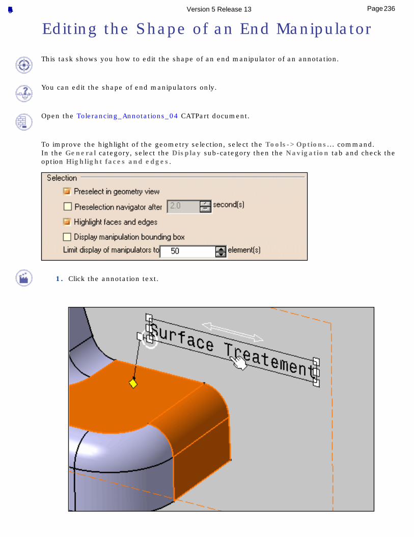
Editing the Shape of an End Manipulator
This task shows you how to edit the shape of an end manipulator of an annotation.
You can edit the shape of end manipulators only.
Open the Tolerancing_Annotations_04 CATPart document.
To improve the highlight of the geometry selection, select the Tools->Options... command.In the General category, select the Display sub-category then the Navigation tab and check the option Highlight faces and edges.
1. Click the annotation text.
236Page Functional Tolerancing & Annotation Version 5 Release 13
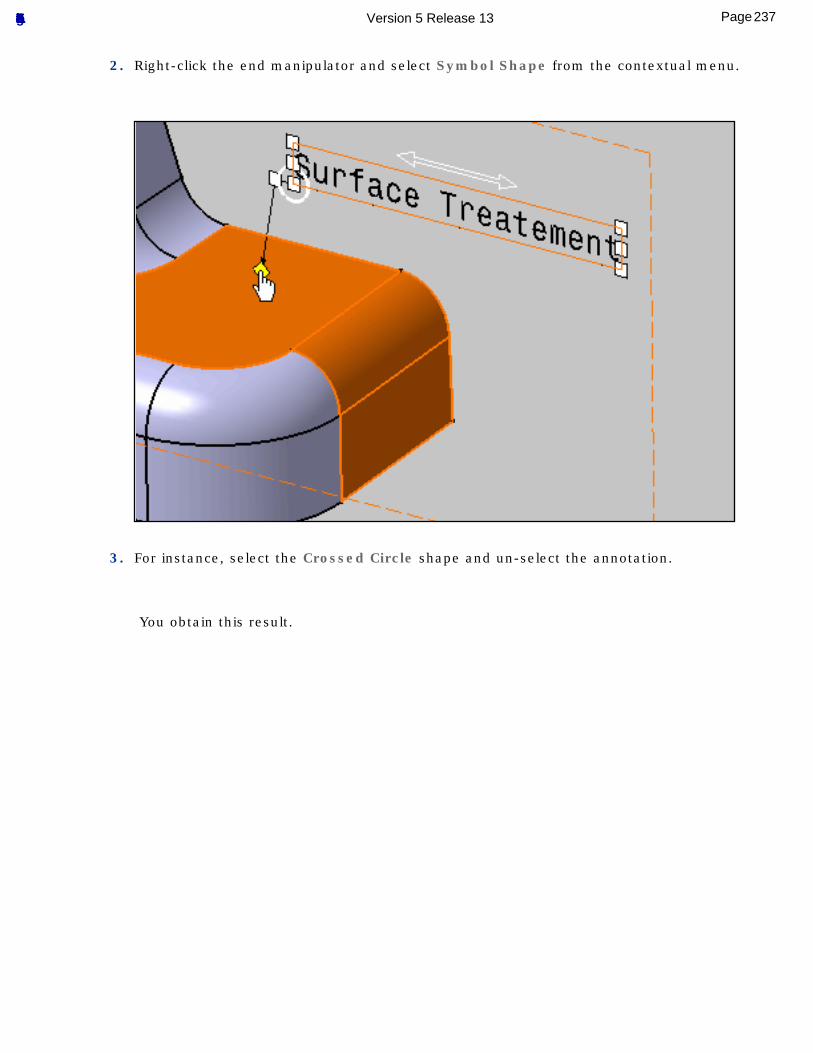
2. Right-click the end manipulator and select Symbol Shape from the contextual menu.
3. For instance, select the Crossed Circle shape and un-select the annotation.
You obtain this result.
237Page Functional Tolerancing & Annotation Version 5 Release 13
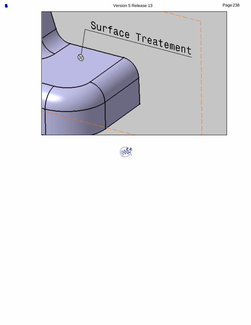
238Page Functional Tolerancing & Annotation Version 5 Release 13
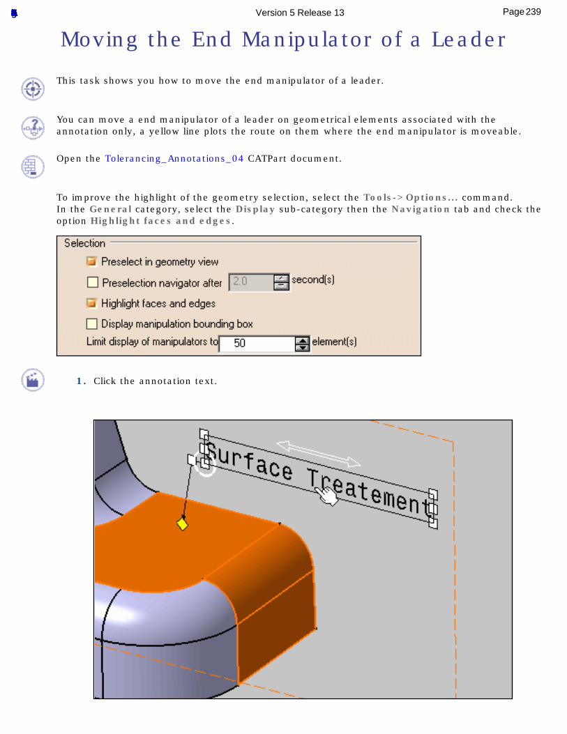
Moving the End Manipulator of a Leader
This task shows you how to move the end manipulator of a leader.
You can move a end manipulator of a leader on geometrical elements associated with the annotation only, a yellow line plots the route on them where the end manipulator is moveable.
Open the Tolerancing_Annotations_04 CATPart document.
To improve the highlight of the geometry selection, select the Tools->Options... command.In the General category, select the Display sub-category then the Navigation tab and check the option Highlight faces and edges.
1. Click the annotation text.
239Page Functional Tolerancing & Annotation Version 5 Release 13
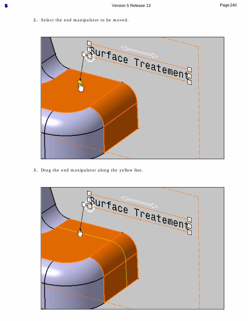
2. Select the end manipulator to be moved.
3. Drag the end manipulator along the yellow line.
240Page Functional Tolerancing & Annotation Version 5 Release 13
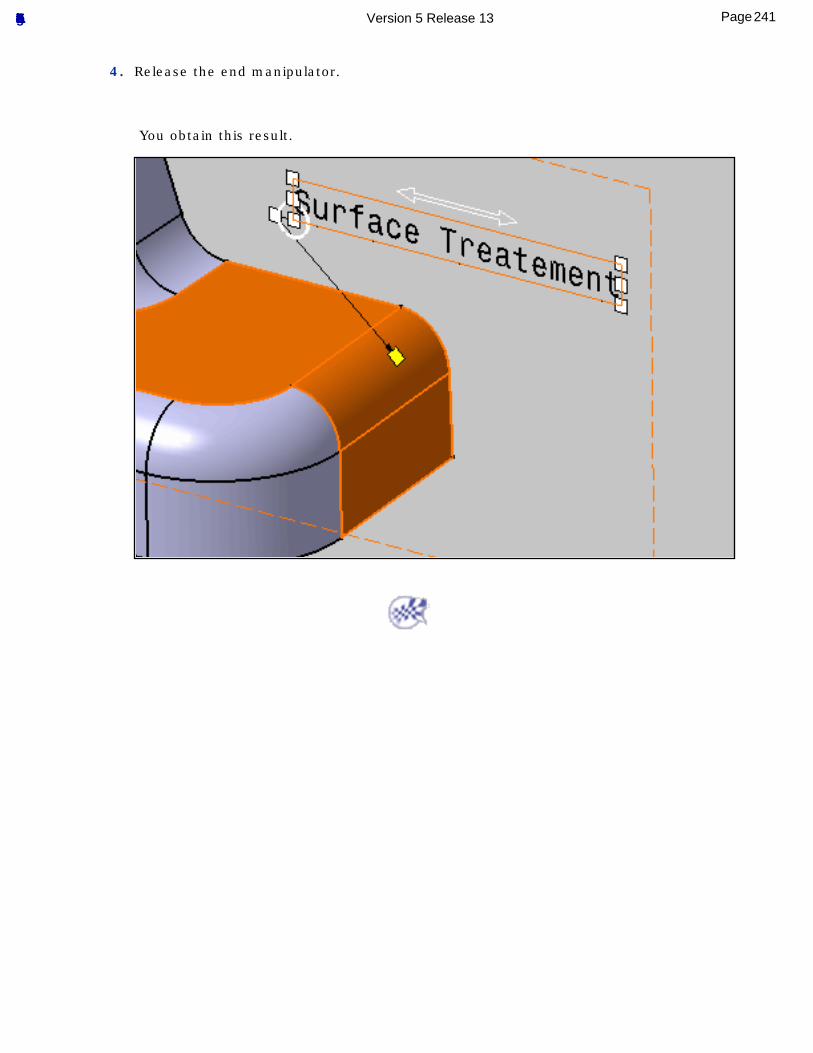
4. Release the end manipulator.
You obtain this result.
241Page Functional Tolerancing & Annotation Version 5 Release 13
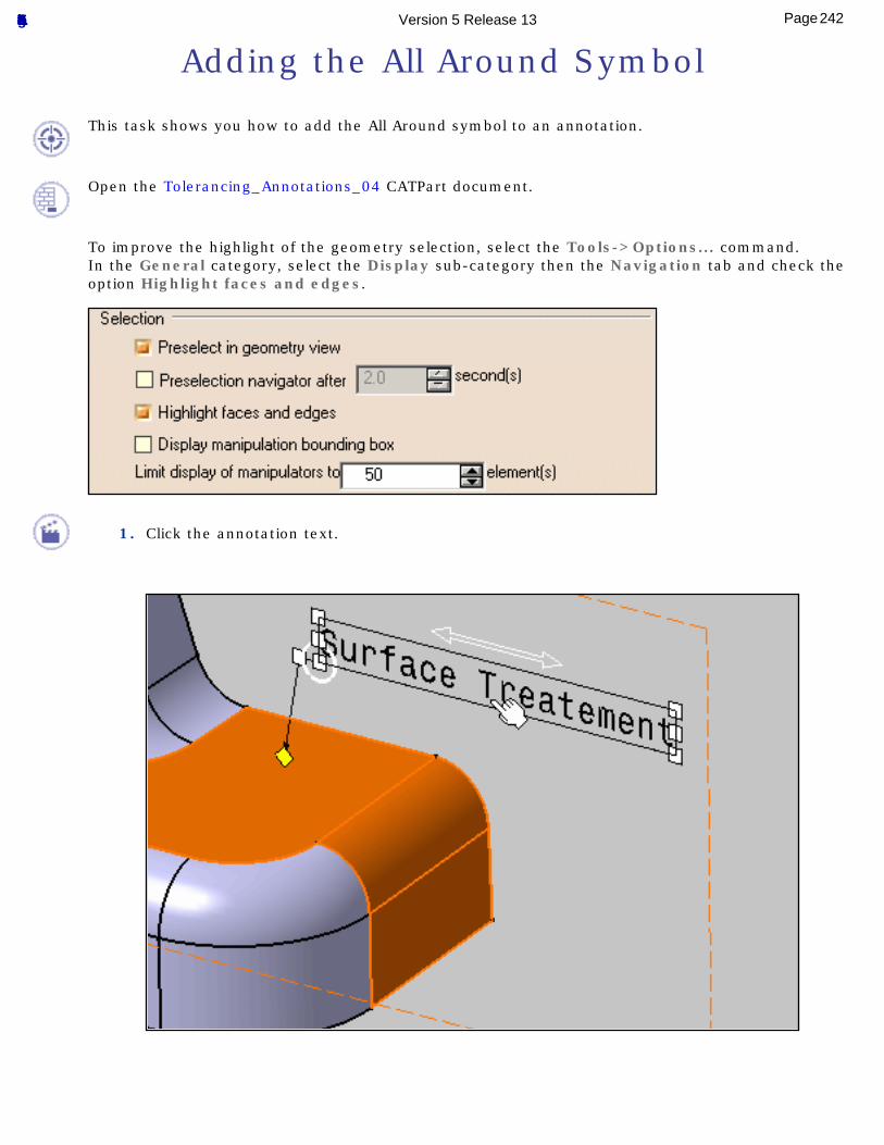
Adding the All Around Symbol
This task shows you how to add the All Around symbol to an annotation.
Open the Tolerancing_Annotations_04 CATPart document.
To improve the highlight of the geometry selection, select the Tools->Options... command.In the General category, select the Display sub-category then the Navigation tab and check the option Highlight faces and edges.
1. Click the annotation text.
242Page Functional Tolerancing & Annotation Version 5 Release 13

2. Right-click any manipulator and check All Around from the contextual menu.
3. Un-select the annotation.
You obtain this result.
243Page Functional Tolerancing & Annotation Version 5 Release 13

244Page Functional Tolerancing & Annotation Version 5 Release 13
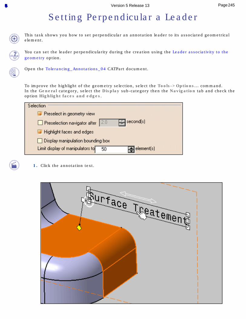
Setting Perpendicular a Leader
This task shows you how to set perpendicular an annotation leader to its associated geometrical element.
You can set the leader perpendicularity during the creation using the Leader associativity to the geometry option.
Open the Tolerancing_Annotations_04 CATPart document.
To improve the highlight of the geometry selection, select the Tools->Options... command.In the General category, select the Display sub-category then the Navigation tab and check the option Highlight faces and edges.
1. Click the annotation text.
245Page Functional Tolerancing & Annotation Version 5 Release 13
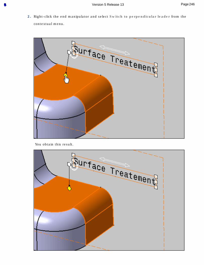
2. Right-click the end manipulator and select Switch to perpendicular leader from the
contextual menu.
You obtain this result.
246Page Functional Tolerancing & Annotation Version 5 Release 13
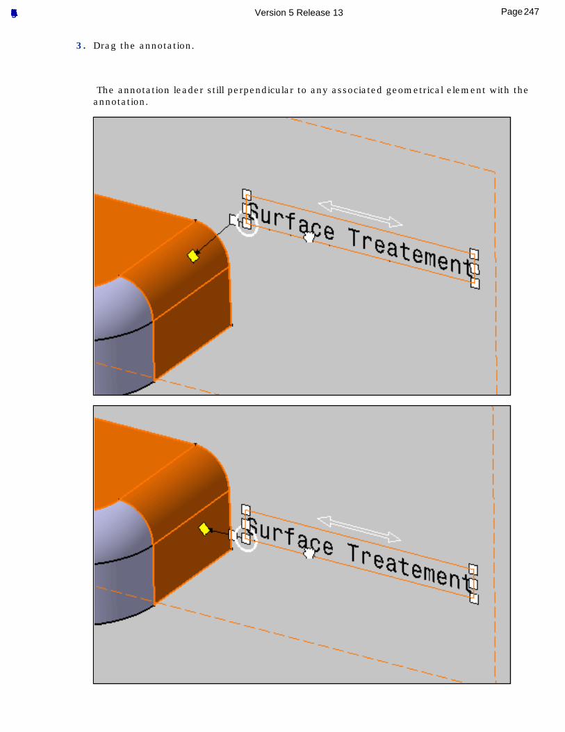
3. Drag the annotation.
The annotation leader still perpendicular to any associated geometrical element with the annotation.
247Page Functional Tolerancing & Annotation Version 5 Release 13
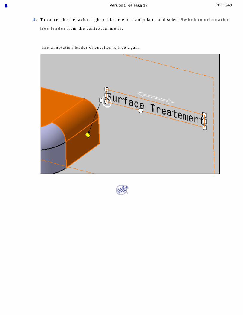
4. To cancel this behavior, right-click the end manipulator and select Switch to orientation
free leader from the contextual menu.
The annotation leader orientation is free again.
248Page Functional Tolerancing & Annotation Version 5 Release 13
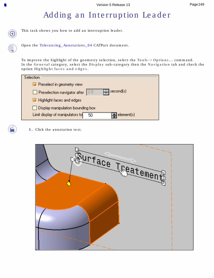
Adding an Interruption Leader
This task shows you how to add an interruption leader.
Open the Tolerancing_Annotations_04 CATPart document.
To improve the highlight of the geometry selection, select the Tools->Options... command.In the General category, select the Display sub-category then the Navigation tab and check the option Highlight faces and edges.
1. Click the annotation text.
249Page Functional Tolerancing & Annotation Version 5 Release 13

2. Right-click the end manipulator and select Add an Interruption from the contextual menu.
3. Indicate the start point of the interruption on the leader.
250Page Functional Tolerancing & Annotation Version 5 Release 13
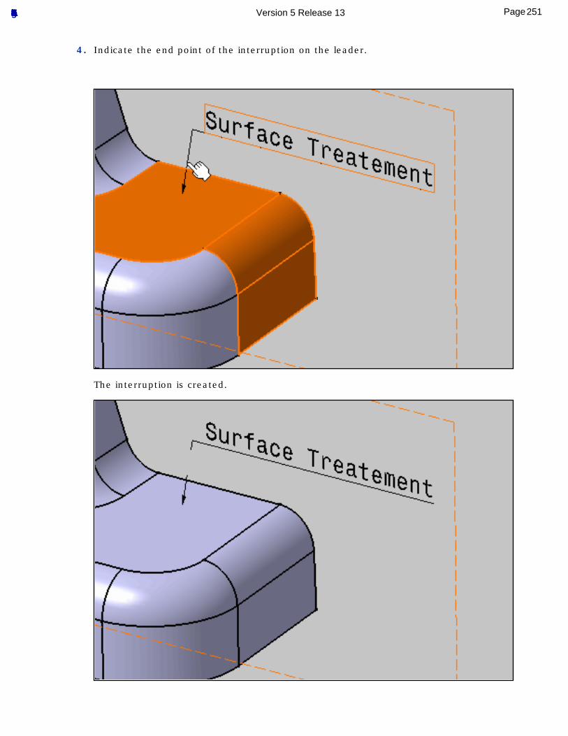
4. Indicate the end point of the interruption on the leader.
The interruption is created.
251Page Functional Tolerancing & Annotation Version 5 Release 13
To remove the interruption, right-click the end manipulator and select Remove Interruptions from the contextual menu.
252Page Functional Tolerancing & Annotation Version 5 Release 13
Managing Graphical Properties
Set Basic Graphical Properties: select the annotation then the desired options from the Text Properties toolbar.
Set Advanced Graphical Properties: select the annotation, the Edit-> Properties command and enter the parameters of your choice to edit the font and the text.
Set Graphical Properties as Default: select the annotation and right-click to select the Set as Default contextual command
Copy Graphical Properties: multi-select the textual annotations which graphic properties are to be modified, click this icon, and select the text to be used as the graphic reference.
253Page Functional Tolerancing & Annotation Version 5 Release 13
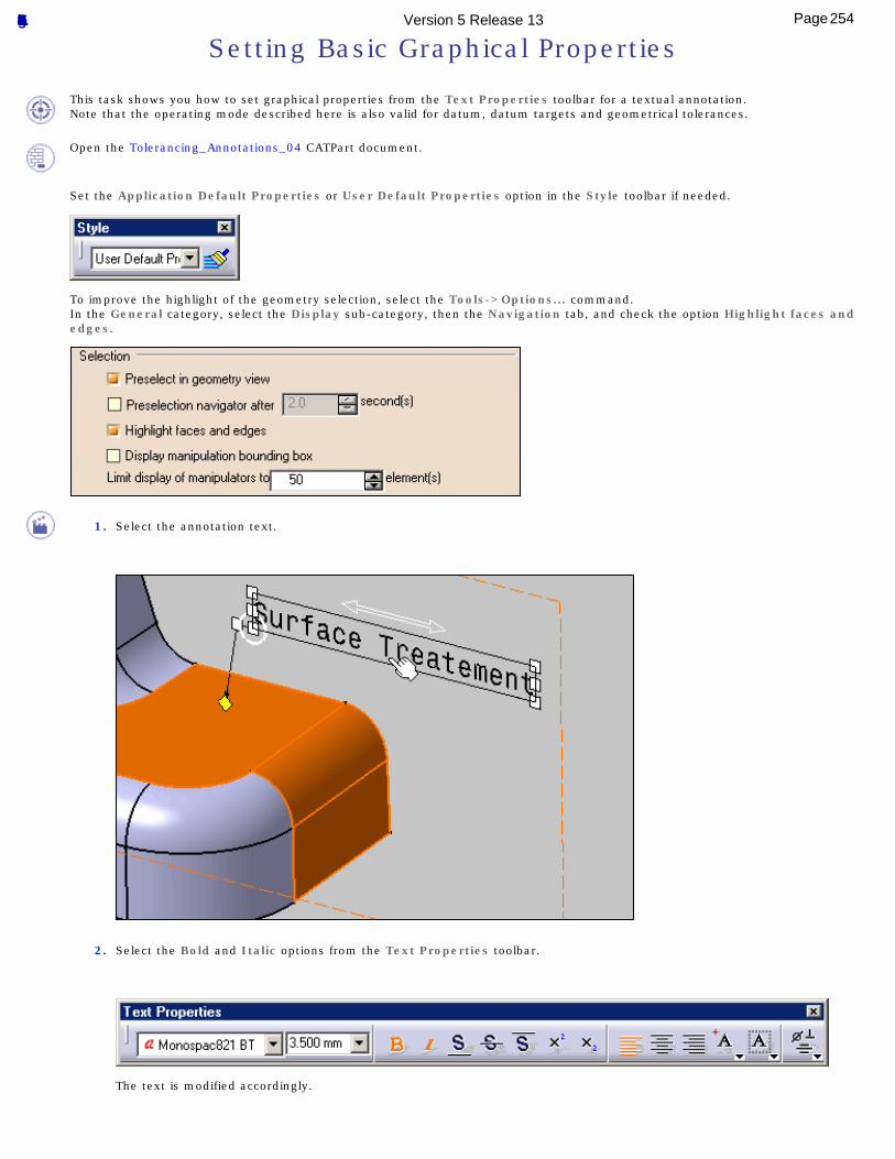
Setting Basic Graphical Properties
This task shows you how to set graphical properties from the Text Properties toolbar for a textual annotation.Note that the operating mode described here is also valid for datum, datum targets and geometrical tolerances.
Open the Tolerancing_Annotations_04 CATPart document.
Set the Application Default Properties or User Default Properties option in the Style toolbar if needed.
To improve the highlight of the geometry selection, select the Tools->Options... command.In the General category, select the Display sub-category, then the Navigation tab, and check the option Highlight faces and edges.
1. Select the annotation text.
2. Select the Bold and Italic options from the Text Properties toolbar.
The text is modified accordingly.
254Page Functional Tolerancing & Annotation Version 5 Release 13
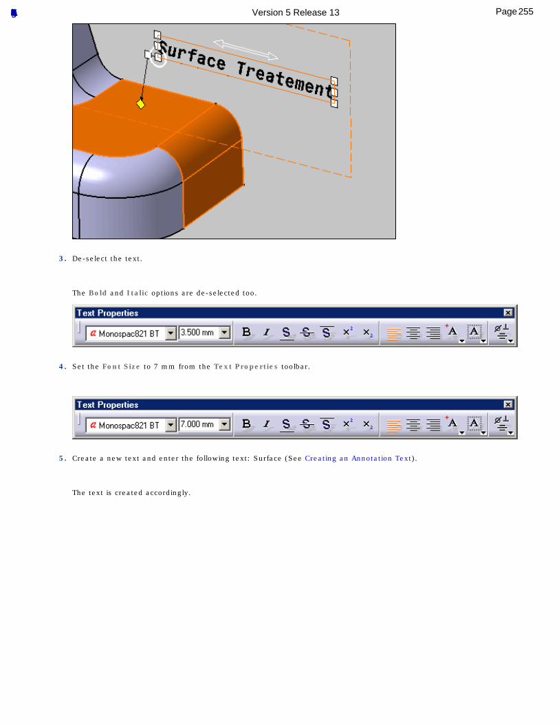
3. De-select the text.
The Bold and Italic options are de-selected too.
4. Set the Font Size to 7 mm from the Text Properties toolbar.
5. Create a new text and enter the following text: Surface (See Creating an Annotation Text).
The text is created accordingly.
255Page Functional Tolerancing & Annotation Version 5 Release 13
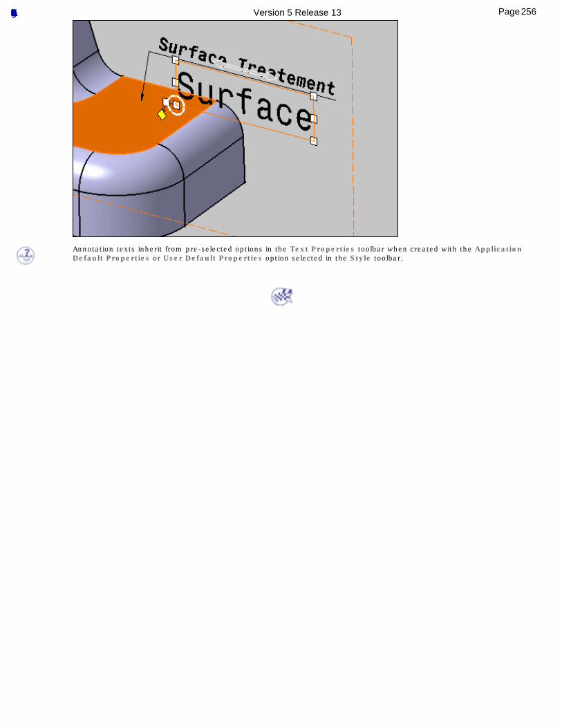
Annotation texts inherit from pre-selected options in the Text Properties toolbar when created with the Application Default Properties or User Default Properties option selected in the Style toolbar.
256Page Functional Tolerancing & Annotation Version 5 Release 13
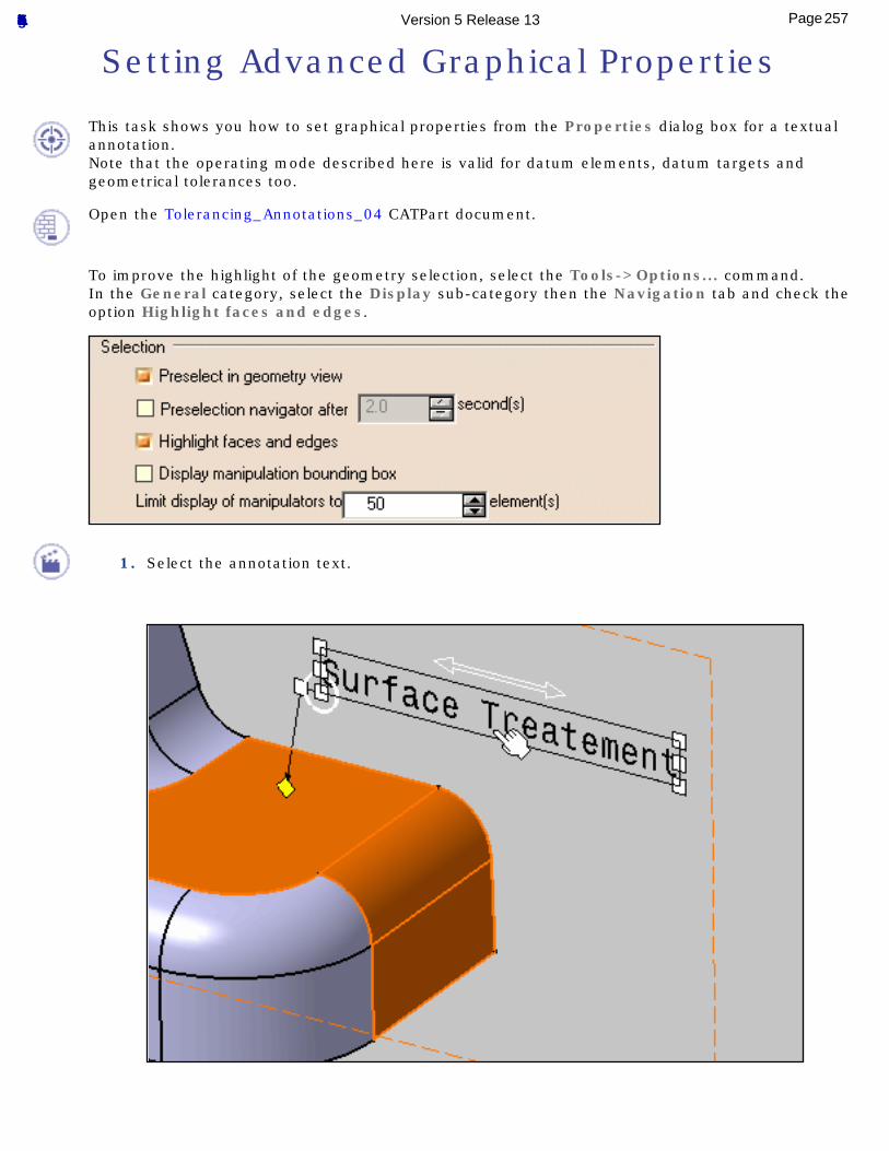
Setting Advanced Graphical Properties
This task shows you how to set graphical properties from the Properties dialog box for a textual annotation.Note that the operating mode described here is valid for datum elements, datum targets and geometrical tolerances too.
Open the Tolerancing_Annotations_04 CATPart document.
To improve the highlight of the geometry selection, select the Tools->Options... command.In the General category, select the Display sub-category then the Navigation tab and check the option Highlight faces and edges.
1. Select the annotation text.
257Page Functional Tolerancing & Annotation Version 5 Release 13
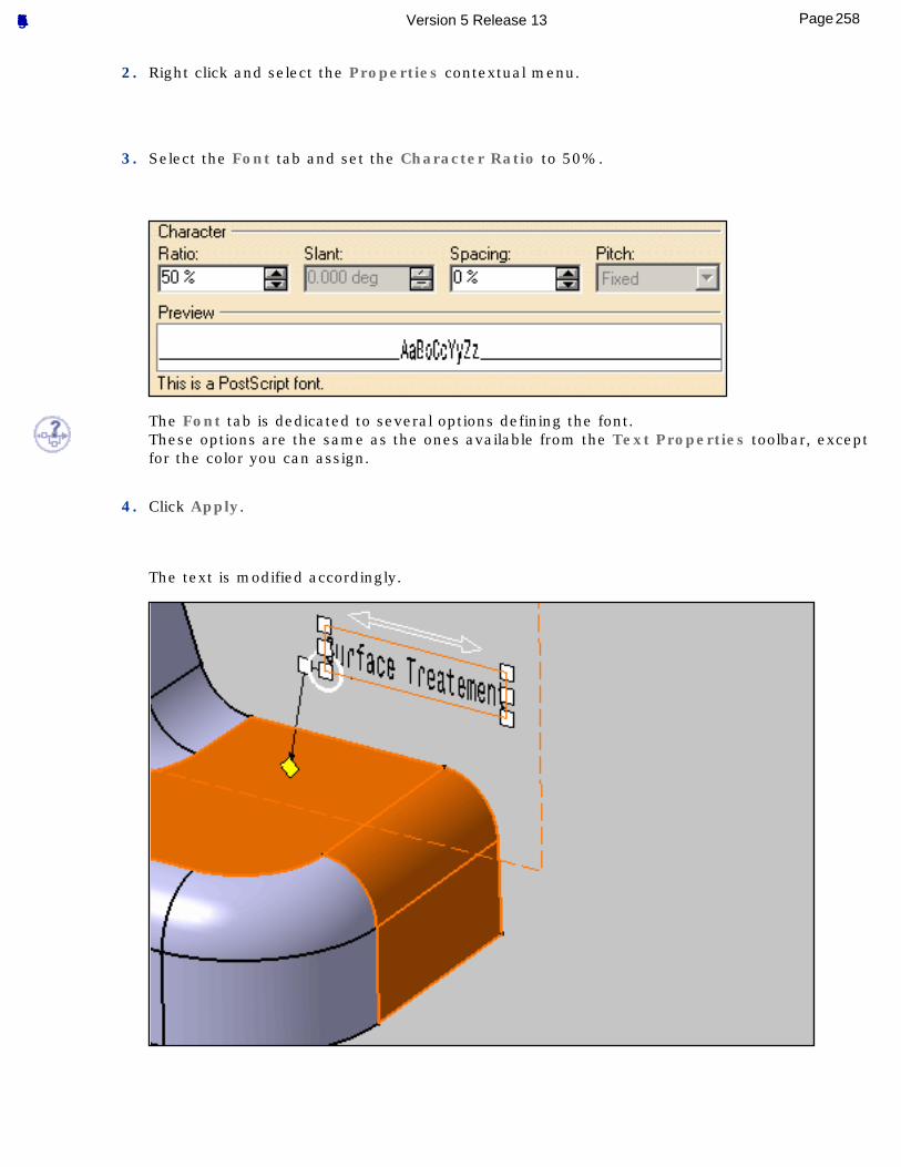
2. Right click and select the Properties contextual menu.
3. Select the Font tab and set the Character Ratio to 50%.
The Font tab is dedicated to several options defining the font.These options are the same as the ones available from the Text Properties toolbar, except for the color you can assign.
4. Click Apply.
The text is modified accordingly.
258Page Functional Tolerancing & Annotation Version 5 Release 13
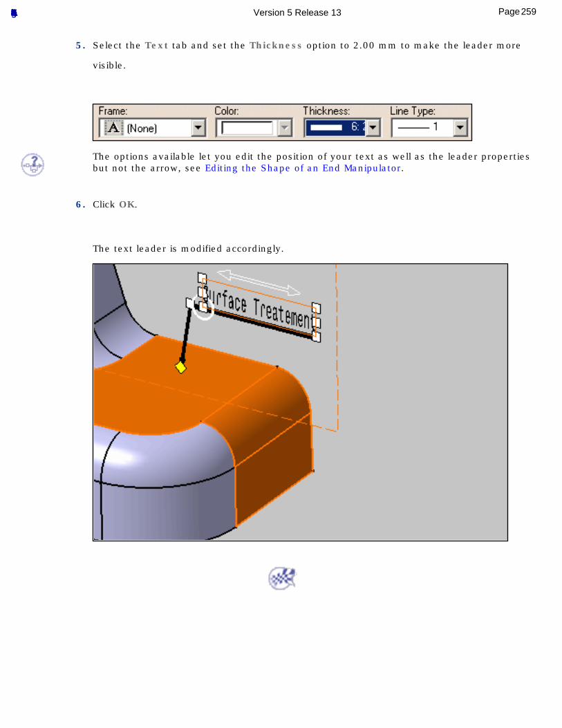
5. Select the Text tab and set the Thickness option to 2.00 mm to make the leader more
visible.
The options available let you edit the position of your text as well as the leader properties but not the arrow, see Editing the Shape of an End Manipulator.
6. Click OK.
The text leader is modified accordingly.
259Page Functional Tolerancing & Annotation Version 5 Release 13
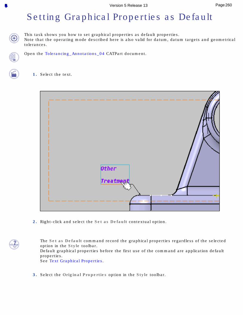
Setting Graphical Properties as Default
This task shows you how to set graphical properties as default properties.Note that the operating mode described here is also valid for datum, datum targets and geometrical tolerances.
Open the Tolerancing_Annotations_04 CATPart document.
1. Select the text.
2. Right-click and select the Set as Default contextual option.
The Set as Default command record the graphical properties regardless of the selected option in the Style toolbar.Default graphical properties before the first use of the command are application default properties.See Text Graphical Properties.
3. Select the Original Properties option in the Style toolbar.
260Page Functional Tolerancing & Annotation Version 5 Release 13
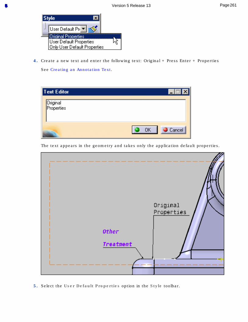
4. Create a new text and enter the following text: Original + Press Enter + Properties
See Creating an Annotation Text.
The text appears in the geometry and takes only the application default properties.
5. Select the User Default Properties option in the Style toolbar.
261Page Functional Tolerancing & Annotation Version 5 Release 13
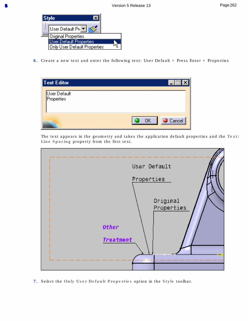
6. Create a new text and enter the following text: User Default + Press Enter + Properties
The text appears in the geometry and takes the application default properties and the Text: Line Spacing property from the first text.
7. Select the Only User Default Properties option in the Style toolbar.
262Page Functional Tolerancing & Annotation Version 5 Release 13
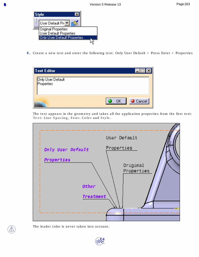
8. Create a new text and enter the following text: Only User Default + Press Enter + Properties
The text appears in the geometry and takes all the application properties from the first text: Text: Line Spacing, Font: Color and Style.
The leader color is never taken into account.
263Page Functional Tolerancing & Annotation Version 5 Release 13
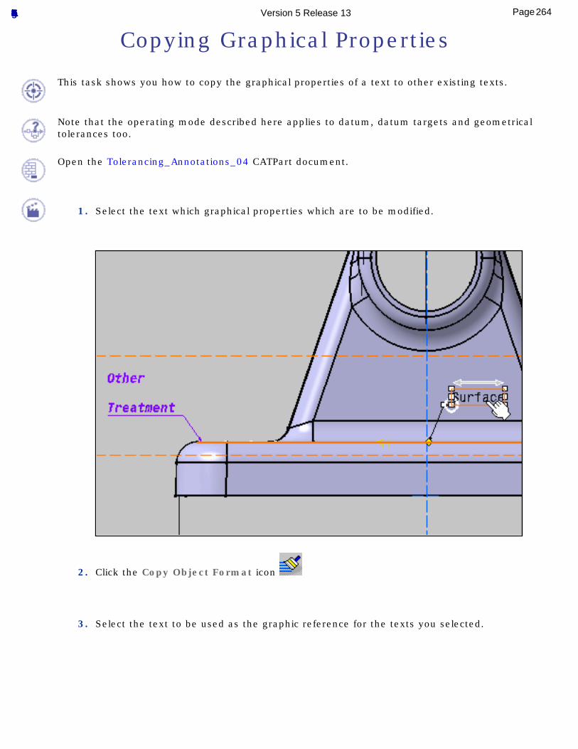
Copying Graphical Properties
This task shows you how to copy the graphical properties of a text to other existing texts.
Note that the operating mode described here applies to datum, datum targets and geometrical tolerances too.
Open the Tolerancing_Annotations_04 CATPart document.
1. Select the text which graphical properties which are to be modified.
2. Click the Copy Object Format icon
3. Select the text to be used as the graphic reference for the texts you selected.
264Page Functional Tolerancing & Annotation Version 5 Release 13
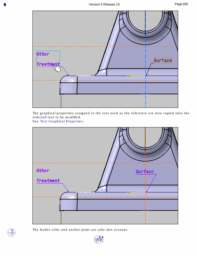
The graphical properties assigned to the text used as the reference are now copied onto the selected text to be modified.See Text Graphical Properties.
The leader color and anchor point are take into account.
265Page Functional Tolerancing & Annotation Version 5 Release 13
Filtering Annotations
Use Annotation Filter: click the icon and specify the filter options.
Create an Annotation Capture: click the icon to create the capture.
Display a Capture: right-click a capture and select Display Capture command from the contextual menu.
Create a Camera: click the icon to create the camera.
Manage Capture Options: set capture options.
Use Capture Management: right-click one or several annotations and select Capture Management command from the contextual menu.
266Page Functional Tolerancing & Annotation Version 5 Release 13
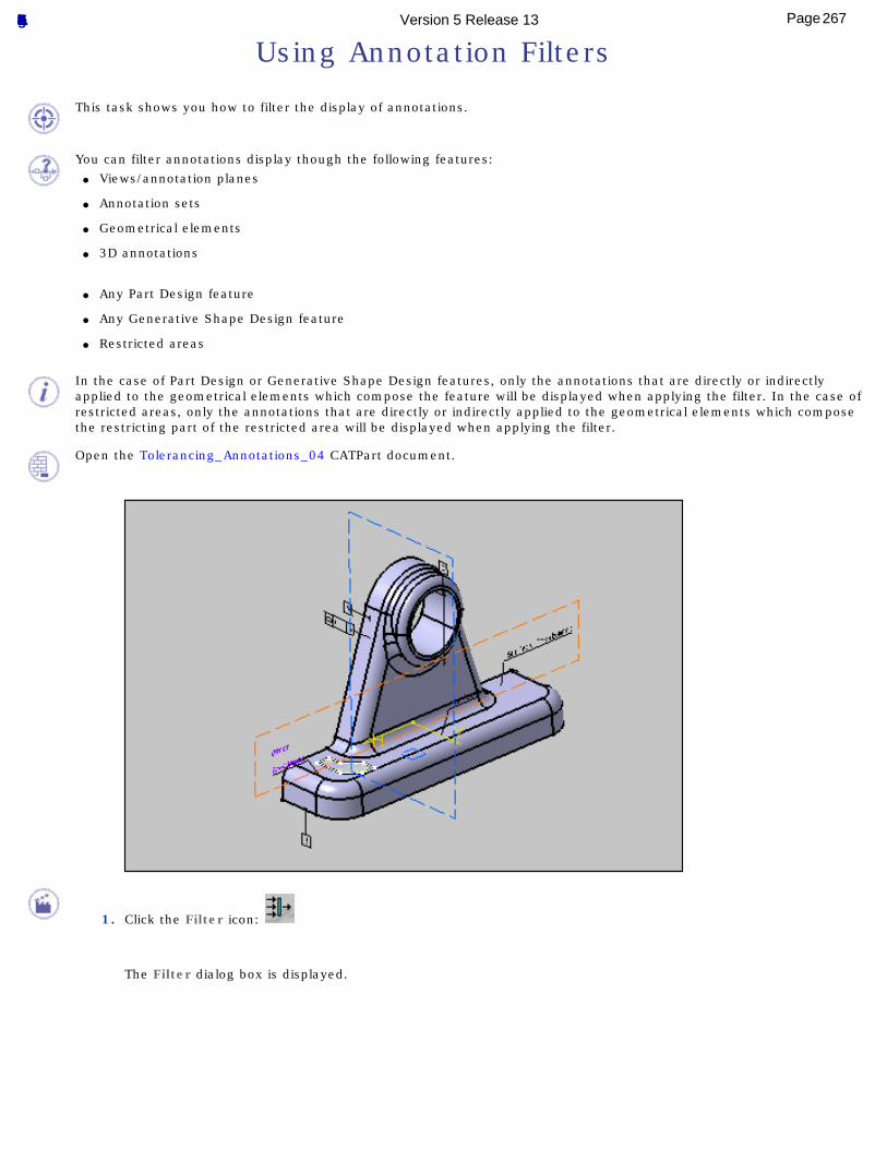
Using Annotation Filters
This task shows you how to filter the display of annotations.
You can filter annotations display though the following features:● Views/annotation planes
● Annotation sets
● Geometrical elements
● 3D annotations
● Any Part Design feature
● Any Generative Shape Design feature
● Restricted areas
In the case of Part Design or Generative Shape Design features, only the annotations that are directly or indirectly applied to the geometrical elements which compose the feature will be displayed when applying the filter. In the case of restricted areas, only the annotations that are directly or indirectly applied to the geometrical elements which compose the restricting part of the restricted area will be displayed when applying the filter.
Open the Tolerancing_Annotations_04 CATPart document.
1. Click the Filter icon:
The Filter dialog box is displayed.
267Page Functional Tolerancing & Annotation Version 5 Release 13
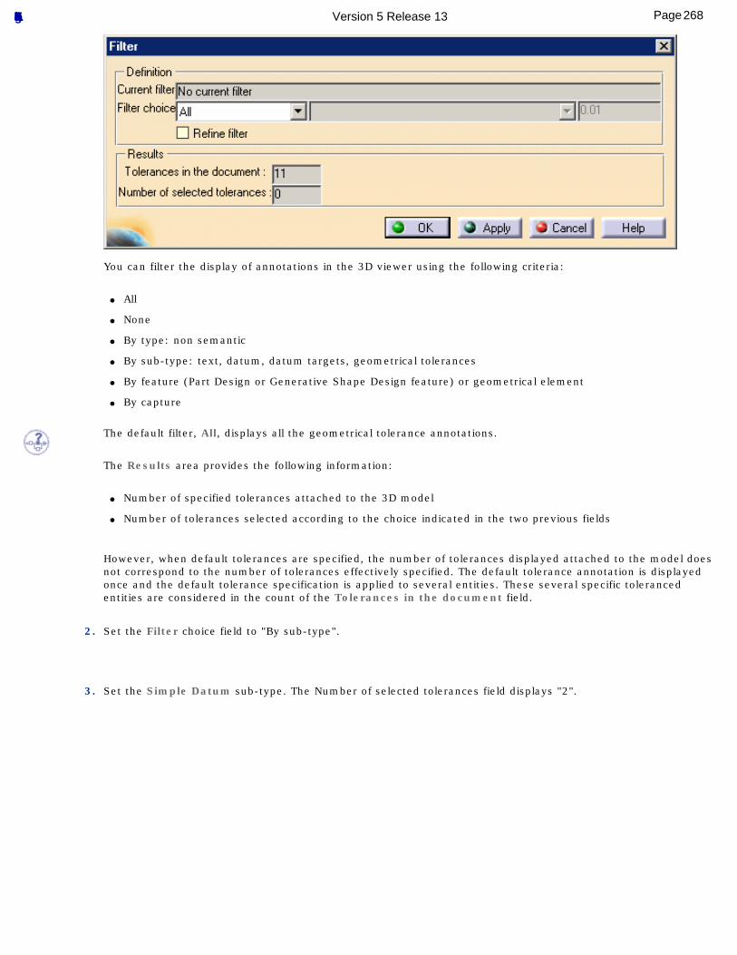
You can filter the display of annotations in the 3D viewer using the following criteria:
● All
● None
● By type: non semantic
● By sub-type: text, datum, datum targets, geometrical tolerances
● By feature (Part Design or Generative Shape Design feature) or geometrical element
● By capture
The default filter, All, displays all the geometrical tolerance annotations.
The Results area provides the following information:
● Number of specified tolerances attached to the 3D model
● Number of tolerances selected according to the choice indicated in the two previous fields
However, when default tolerances are specified, the number of tolerances displayed attached to the model does not correspond to the number of tolerances effectively specified. The default tolerance annotation is displayed once and the default tolerance specification is applied to several entities. These several specific toleranced entities are considered in the count of the Tolerances in the document field.
2. Set the Filter choice field to "By sub-type".
3. Set the Simple Datum sub-type. The Number of selected tolerances field displays "2".
268Page Functional Tolerancing & Annotation Version 5 Release 13
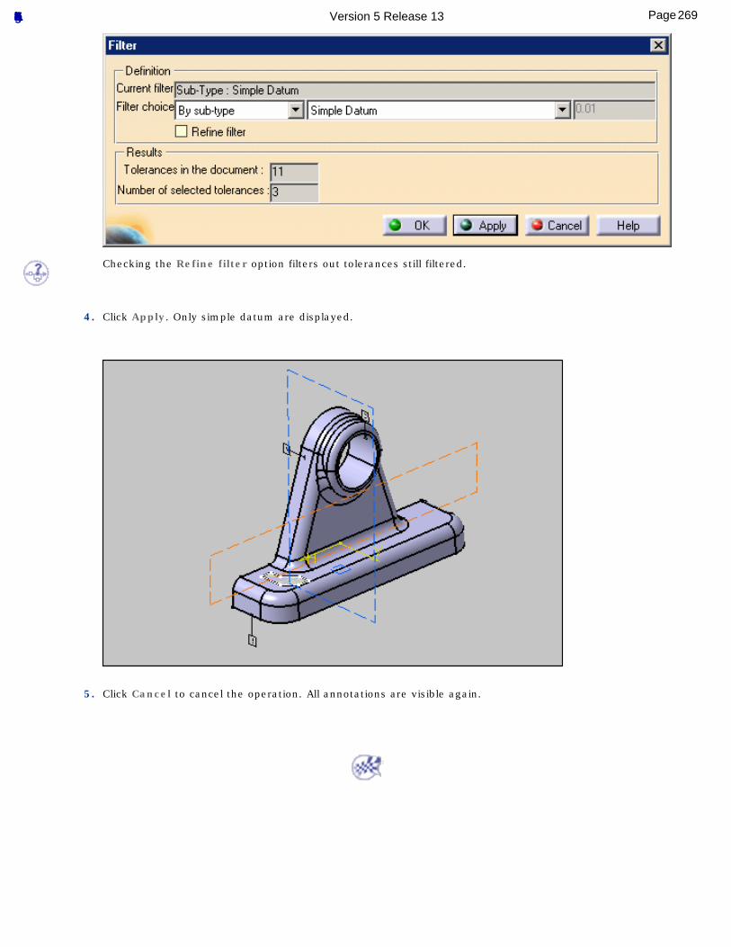
Checking the Refine filter option filters out tolerances still filtered.
4. Click Apply. Only simple datum are displayed.
5. Click Cancel to cancel the operation. All annotations are visible again.
269Page Functional Tolerancing & Annotation Version 5 Release 13
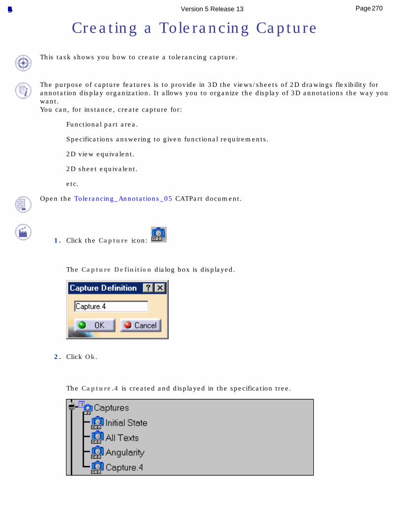
Creating a Tolerancing Capture
This task shows you how to create a tolerancing capture.
The purpose of capture features is to provide in 3D the views/sheets of 2D drawings flexibility for annotation display organization. It allows you to organize the display of 3D annotations the way you want.You can, for instance, create capture for:
Functional part area.
Specifications answering to given functional requirements.
2D view equivalent.
2D sheet equivalent.
etc.
Open the Tolerancing_Annotations_05 CATPart document.
1. Click the Capture icon:
The Capture Definition dialog box is displayed.
2. Click Ok.
The Capture.4 is created and displayed in the specification tree.
270Page Functional Tolerancing & Annotation Version 5 Release 13
You are now in the Tolerancing & Annotation Captures workshop.
2. Click the Exit from capture icon:
You are back in the Functional Tolerancing & Annotations workbench.
To edit a capture, double-click the capture in the specification tree.
271Page Functional Tolerancing & Annotation Version 5 Release 13
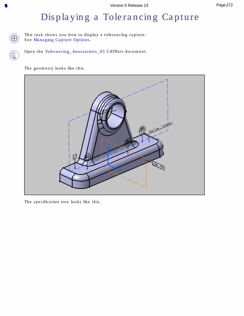
Displaying a Tolerancing Capture
This task shows you how to display a tolerancing capture.See Managing Capture Options.
Open the Tolerancing_Annotations_05 CATPart document.
The geometry looks like this.
The specification tree looks like this.
272Page Functional Tolerancing & Annotation Version 5 Release 13
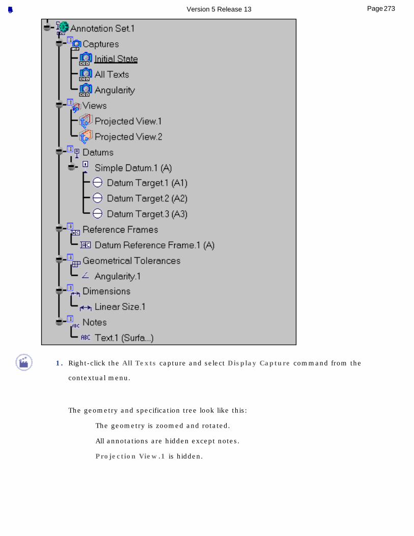
1. Right-click the All Texts capture and select Display Capture command from the
contextual menu.
The geometry and specification tree look like this:
The geometry is zoomed and rotated.
All annotations are hidden except notes.
Projection View.1 is hidden.
273Page Functional Tolerancing & Annotation Version 5 Release 13
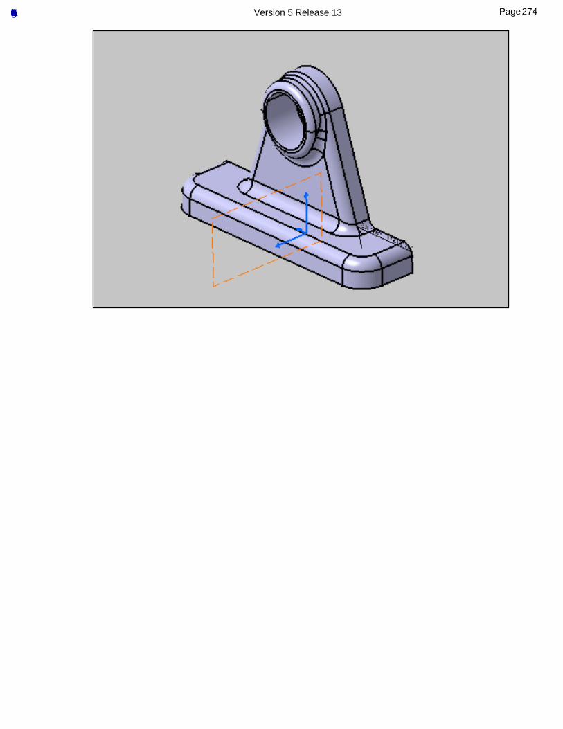
274Page Functional Tolerancing & Annotation Version 5 Release 13
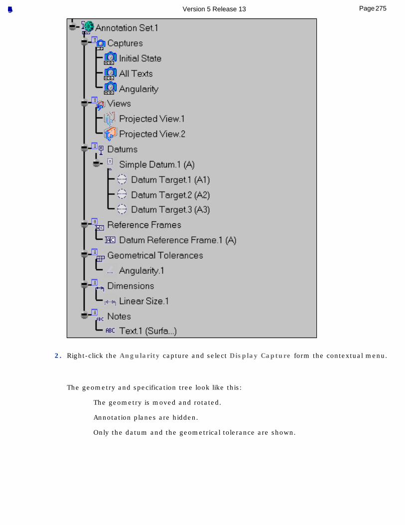
2. Right-click the Angularity capture and select Display Capture form the contextual menu.
The geometry and specification tree look like this:
The geometry is moved and rotated.
Annotation planes are hidden.
Only the datum and the geometrical tolerance are shown.
275Page Functional Tolerancing & Annotation Version 5 Release 13
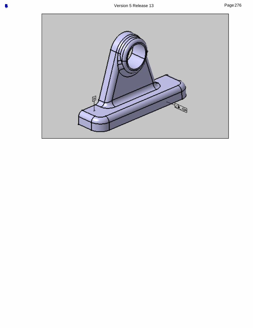
276Page Functional Tolerancing & Annotation Version 5 Release 13
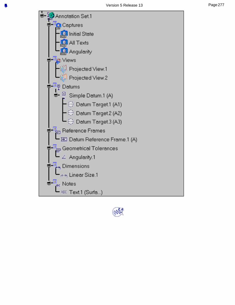
277Page Functional Tolerancing & Annotation Version 5 Release 13
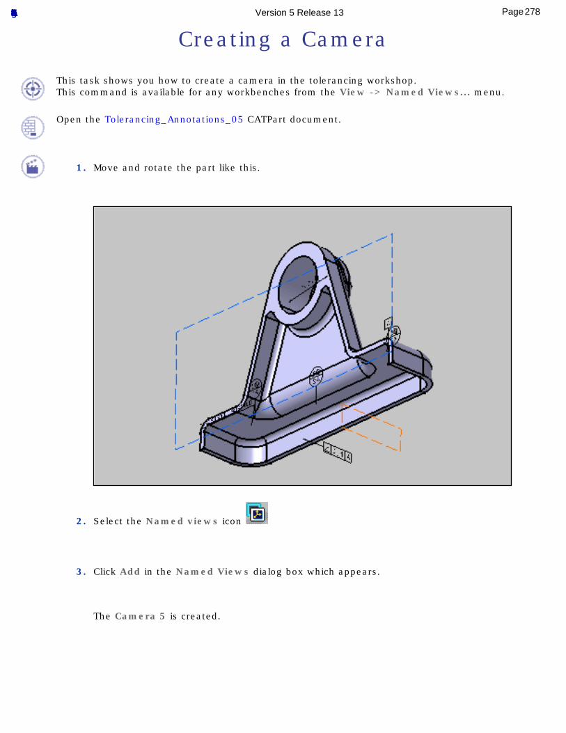
Creating a Camera
This task shows you how to create a camera in the tolerancing workshop.This command is available for any workbenches from the View -> Named Views... menu.
Open the Tolerancing_Annotations_05 CATPart document.
1. Move and rotate the part like this.
2. Select the Named views icon
3. Click Add in the Named Views dialog box which appears.
The Camera 5 is created.
278Page Functional Tolerancing & Annotation Version 5 Release 13
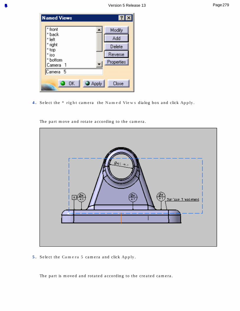
4. Select the * right camera the Named Views dialog box and click Apply.
The part move and rotate according to the camera.
5. Select the Camera 5 camera and click Apply.
The part is moved and rotated according to the created camera.
279Page Functional Tolerancing & Annotation Version 5 Release 13
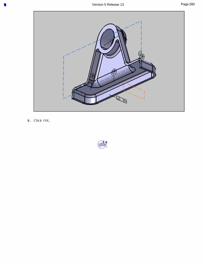
6. Click OK.
280Page Functional Tolerancing & Annotation Version 5 Release 13
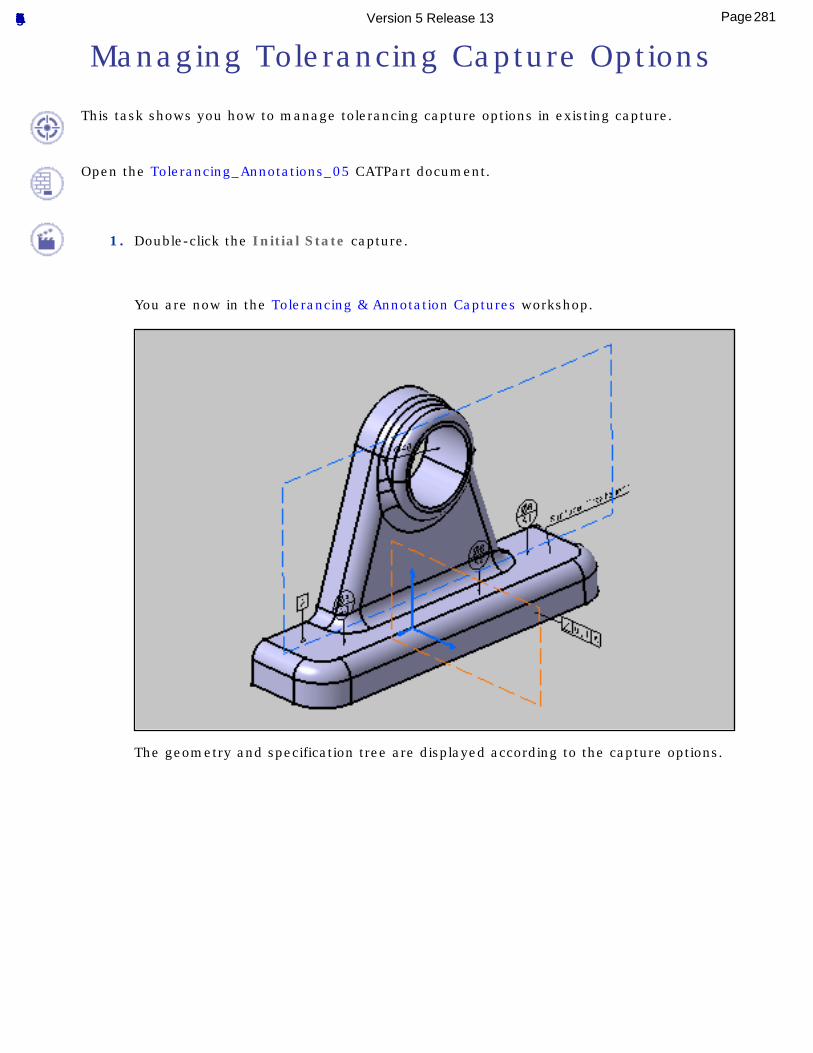
Managing Tolerancing Capture Options
This task shows you how to manage tolerancing capture options in existing capture.
Open the Tolerancing_Annotations_05 CATPart document.
1. Double-click the Initial State capture.
You are now in the Tolerancing & Annotation Captures workshop.
The geometry and specification tree are displayed according to the capture options.
281Page Functional Tolerancing & Annotation Version 5 Release 13
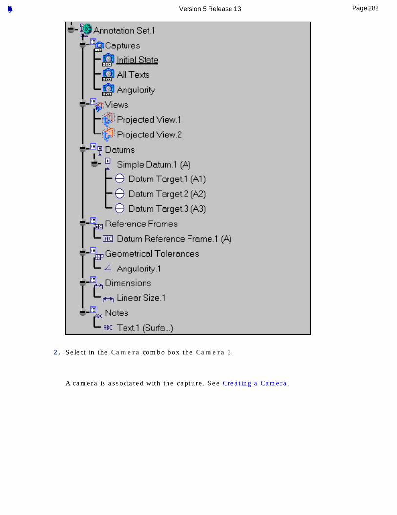
2. Select in the Camera combo box the Camera 3.
A camera is associated with the capture. See Creating a Camera.
282Page Functional Tolerancing & Annotation Version 5 Release 13
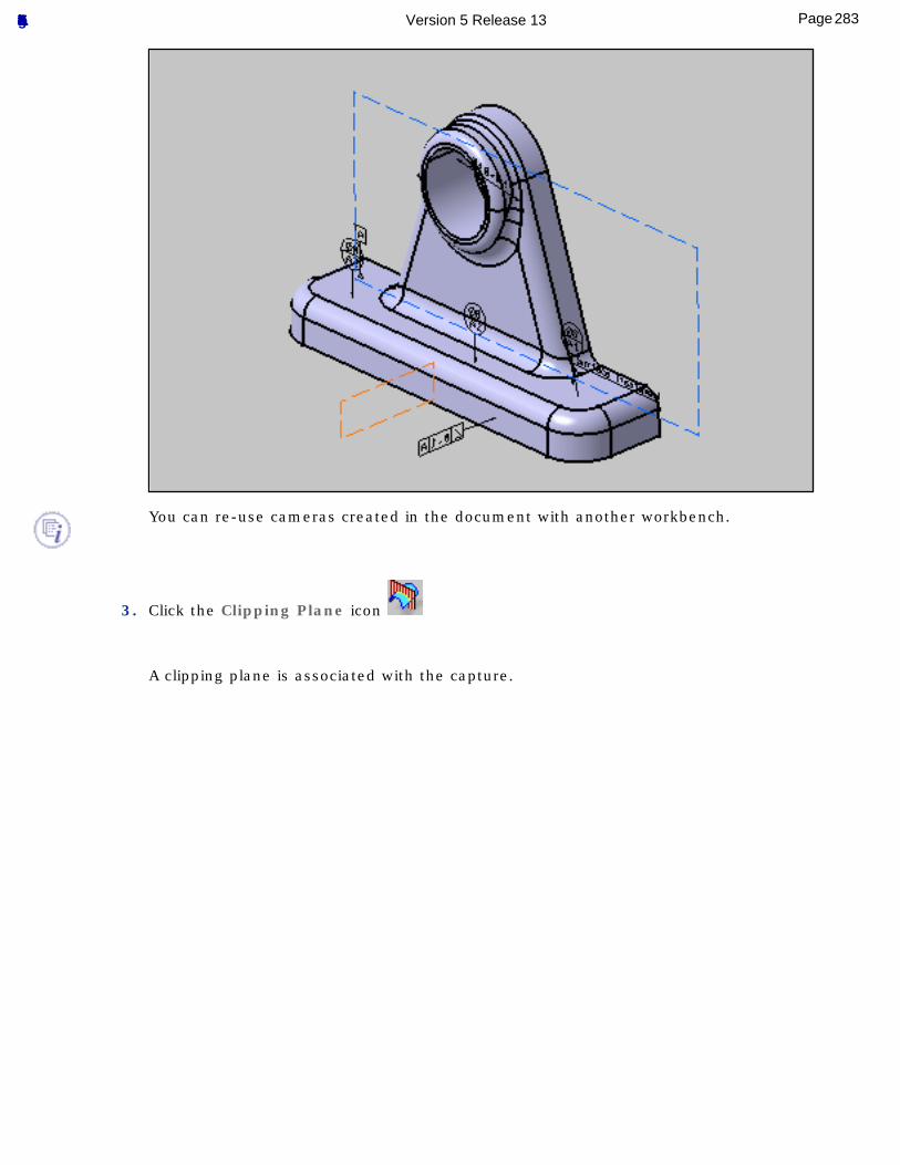
You can re-use cameras created in the document with another workbench.
3. Click the Clipping Plane icon
A clipping plane is associated with the capture.
283Page Functional Tolerancing & Annotation Version 5 Release 13
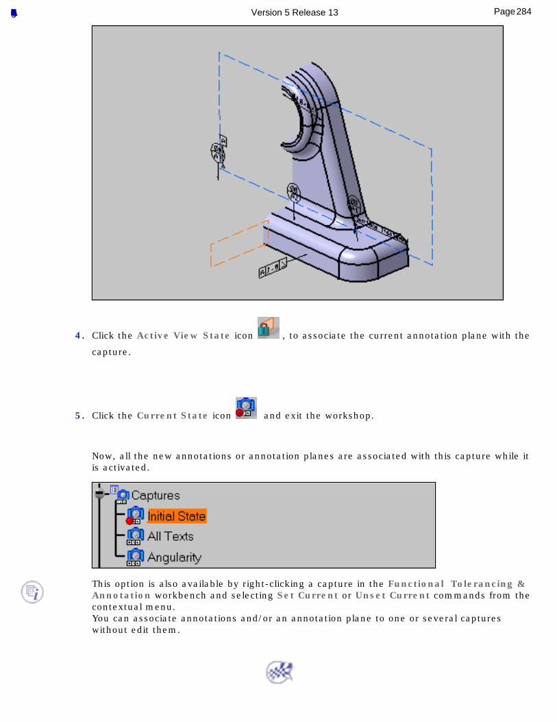
4. Click the Active View State icon , to associate the current annotation plane with the
capture.
5. Click the Current State icon and exit the workshop.
Now, all the new annotations or annotation planes are associated with this capture while it is activated.
This option is also available by right-clicking a capture in the Functional Tolerancing & Annotation workbench and selecting Set Current or Unset Current commands from the contextual menu.You can associate annotations and/or an annotation plane to one or several captures without edit them.
284Page Functional Tolerancing & Annotation Version 5 Release 13
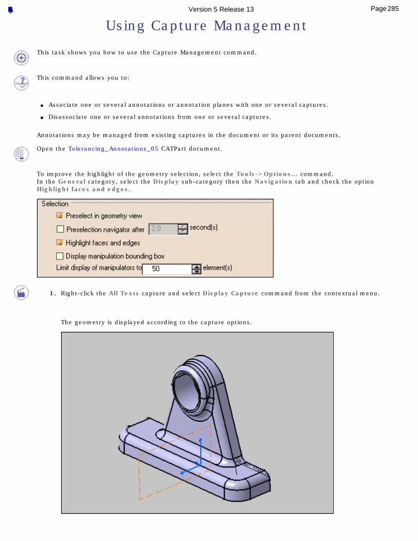
Using Capture Management
This task shows you how to use the Capture Management command.
This command allows you to:
● Associate one or several annotations or annotation planes with one or several captures.
● Disassociate one or several annotations from one or several captures.
Annotations may be managed from existing captures in the document or its parent documents.
Open the Tolerancing_Annotations_05 CATPart document.
To improve the highlight of the geometry selection, select the Tools->Options... command.In the General category, select the Display sub-category then the Navigation tab and check the option Highlight faces and edges.
1. Right-click the All Texts capture and select Display Capture command from the contextual menu.
The geometry is displayed according to the capture options.
285Page Functional Tolerancing & Annotation Version 5 Release 13
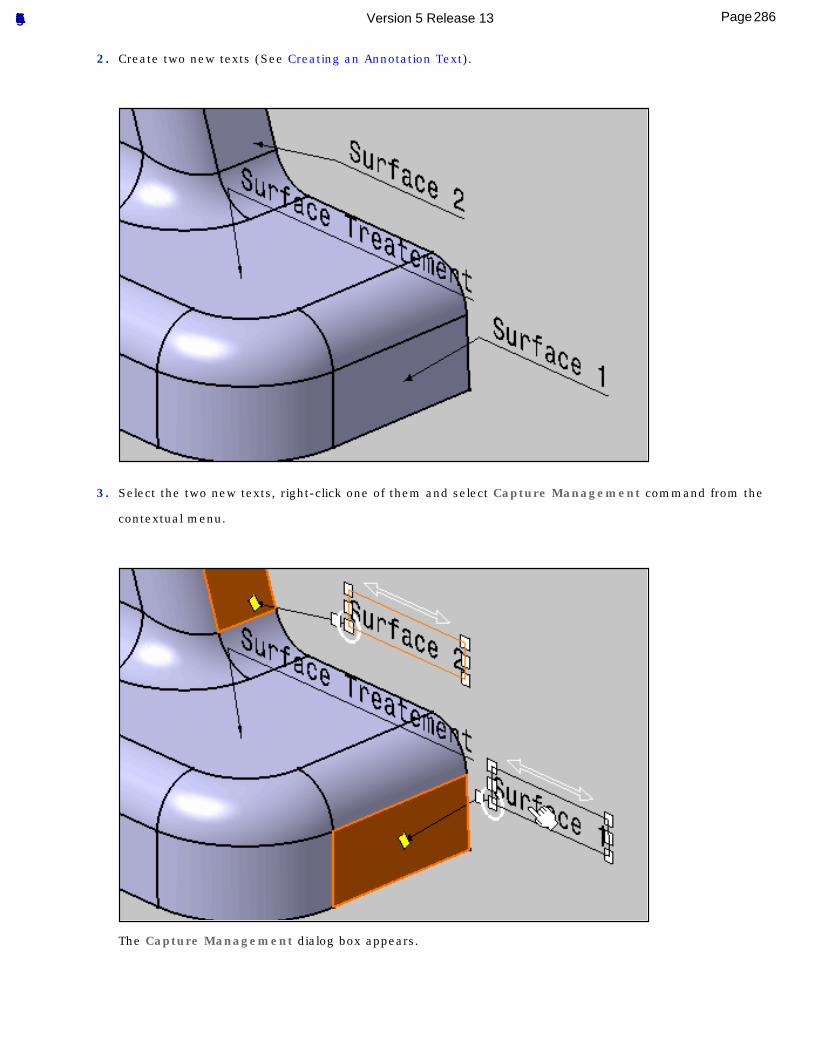
2. Create two new texts (See Creating an Annotation Text).
3. Select the two new texts, right-click one of them and select Capture Management command from the
contextual menu.
The Capture Management dialog box appears.
286Page Functional Tolerancing & Annotation Version 5 Release 13
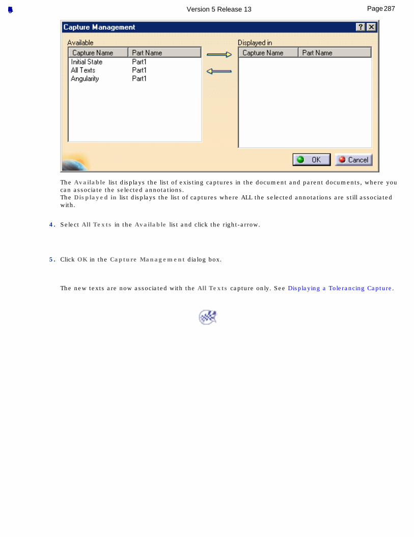
The Available list displays the list of existing captures in the document and parent documents, where you can associate the selected annotations.The Displayed in list displays the list of captures where ALL the selected annotations are still associated with.
4. Select All Texts in the Available list and click the right-arrow.
5. Click OK in the Capture Management dialog box.
The new texts are now associated with the All Texts capture only. See Displaying a Tolerancing Capture.
287Page Functional Tolerancing & Annotation Version 5 Release 13
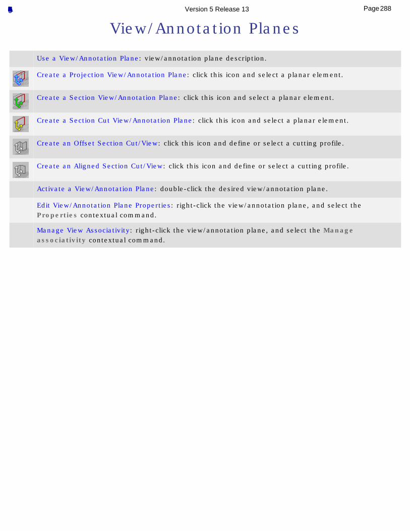
View/Annotation Planes
Use a View/Annotation Plane: view/annotation plane description.
Create a Projection View/Annotation Plane: click this icon and select a planar element.
Create a Section View/Annotation Plane: click this icon and select a planar element.
Create a Section Cut View/Annotation Plane: click this icon and select a planar element.
Create an Offset Section Cut/View: click this icon and define or select a cutting profile.
Create an Aligned Section Cut/View: click this icon and define or select a cutting profile.
Activate a View/Annotation Plane: double-click the desired view/annotation plane.
Edit View/Annotation Plane Properties: right-click the view/annotation plane, and select the Properties contextual command.
Manage View Associativity: right-click the view/annotation plane, and select the Manage associativity contextual command.
288Page Functional Tolerancing & Annotation Version 5 Release 13
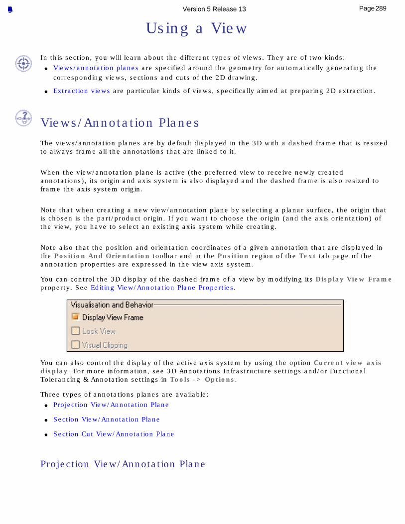
Using a View
In this section, you will learn about the different types of views. They are of two kinds:● Views/annotation planes are specified around the geometry for automatically generating the
corresponding views, sections and cuts of the 2D drawing.
● Extraction views are particular kinds of views, specifically aimed at preparing 2D extraction.
Views/Annotation Planes The views/annotation planes are by default displayed in the 3D with a dashed frame that is resized
to always frame all the annotations that are linked to it.
When the view/annotation plane is active (the preferred view to receive newly created annotations), its origin and axis system is also displayed and the dashed frame is also resized to frame the axis system origin.
Note that when creating a new view/annotation plane by selecting a planar surface, the origin that is chosen is the part/product origin. If you want to choose the origin (and the axis orientation) of the view, you have to select an existing axis system while creating.
Note also that the position and orientation coordinates of a given annotation that are displayed in the Position And Orientation toolbar and in the Position region of the Text tab page of the annotation properties are expressed in the view axis system.
You can control the 3D display of the dashed frame of a view by modifying its Display View Frame property. See Editing View/Annotation Plane Properties.
You can also control the display of the active axis system by using the option Current view axis display. For more information, see 3D Annotations Infrastructure settings and/or Functional Tolerancing & Annotation settings in Tools -> Options.
Three types of annotations planes are available:● Projection View/Annotation Plane
● Section View/Annotation Plane
● Section Cut View/Annotation Plane
Projection View/Annotation Plane
289Page Functional Tolerancing & Annotation Version 5 Release 13
A projection view/annotation plane allows you to manage 3D annotations:● Located in planes both parallel to this view/annotation plane and in the background and
foreground spaces bounded by this view/annotation plane (or in any plane of the direction of planes defined by this view/annotation plane),
● Related to the geometry finding an intersection with this view/annotation plane,
● Lying on/belonging to this view/annotation plane.
This view/annotation plane allows you to specify a particular view/annotation plane for generating embedded 2D front/projection views, in the Generative Drafting workbench, during the 2D extraction of the 3D part and of the 3D annotations.
Annotations can be translated along the z axis of its local coordinate system.Negative and positive z values can be used to define the translation, since the projection view/annotation plane will be used for the extraction of front views in the Generative Drafting workbench.
See Creating a Projection View/Annotation Plane.
Section View/Annotation Plane
A section view/annotation plane allows you to manage 3D annotations:● Located in planes both parallel to this view/annotation plane and in the background space
bounded by this view/annotation plane,
● Related to the geometry finding an intersection with this view/annotation plane,
● Lying on/belonging to this view/annotation plane.
This view allows you to specify a particular annotation for generating embedded 2D section views, in the Generative Drafting workbench, during the 2D extraction of the 3D part and of the 3D annotations.
Annotations can be translated along the z axis of its local coordinate system.Only negative z values can be used to define the translation, since the section view/annotation plane will be used for the extraction of section views in the Generative Drafting workbench.
See Creating a Section View/Annotation Plane.
Section Cut View/Annotation Plane
A section cut view/annotation plane allows you to manage 3D annotations:● Only related to the geometry finding an intersection with this view/annotation plane,
● Related to the geometry finding an intersection with this view/annotation plane.
This view allows you to specify a particular annotation for generating embedded 2D section views, in the Generative Drafting workbench, during the 2D extraction of the 3D part and of the 3D annotations.
Annotations cannot be translated along the z axis of its local coordinate system (z=0), since the section cut view/annotation plane will be used for the extraction of section cuts in the Generative Drafting workbench.
See Creating a Section Cut View/Annotation Plane.
290Page Functional Tolerancing & Annotation Version 5 Release 13
Extraction ViewsExtraction views are particular kinds of views. They specifically aimed at preparing the following types of views for 2D extraction:
● aligned section views/section cuts
● offset section views/section cuts
Extraction views are made up of several annotation planes (of the same type). You can create annotations in each view/annotation plane making up the extraction view. You will then be able to extract this extraction view to 2D in the Generative Drafting workbench, as well as all annotations defined in each component section view.
Extraction views, no matter their type, use a cutting profile as cutting plane.
Aligned section views/section cuts
An aligned section view/aligned section cut is created from a cutting profile defined from non parallel planes. In order to include in a section certain angled elements, the cutting plane may be bent so as to pass through those features. The plane and feature are then imagined to be revolved into the original plane.
Aligned section views are made up of several section views/annotation planes, as described in Section View/Annotation Plane above.
Aligned section cuts are made up of several section cut views/annotation planes, as described in Section Cut View/Annotation Plane above.
Offset section views/section cuts
Offset section views/offset section cuts let you show several features that do not lie in a straight line by offsetting or bending the cutting plane, which is often desirable when sectioning through irregular objects.
Offset section views are made up of several section views/annotation planes, as described in Section View/Annotation Plane above.
Offset section cuts are made up of several section cut views/annotation planes, as described in Section Cut View/Annotation Plane above.
291Page Functional Tolerancing & Annotation Version 5 Release 13
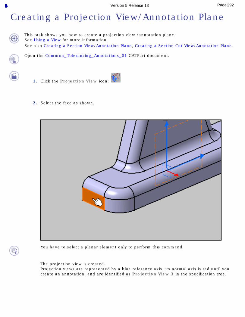
Creating a Projection View/Annotation Plane
This task shows you how to create a projection view /annotation plane.See Using a View for more information.See also Creating a Section View/Annotation Plane, Creating a Section Cut View/Annotation Plane.
Open the Common_Tolerancing_Annotations_01 CATPart document.
1. Click the Projection View icon:
2. Select the face as shown.
You have to select a planar element only to perform this command.
The projection view is created.Projection views are represented by a blue reference axis, its normal axis is red until you create an annotation, and are identified as Projection View.3 in the specification tree.
292Page Functional Tolerancing & Annotation Version 5 Release 13
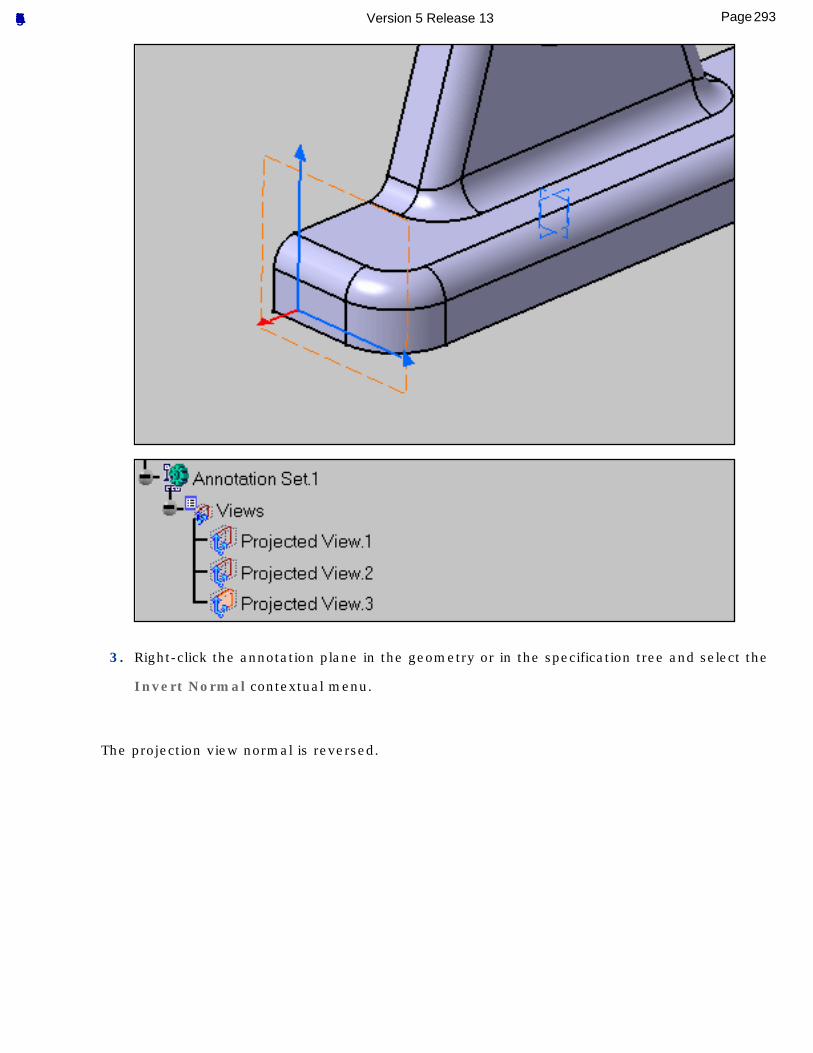
3. Right-click the annotation plane in the geometry or in the specification tree and select the
Invert Normal contextual menu.
The projection view normal is reversed.
293Page Functional Tolerancing & Annotation Version 5 Release 13
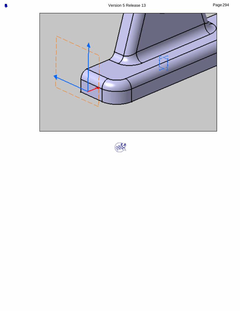
294Page Functional Tolerancing & Annotation Version 5 Release 13
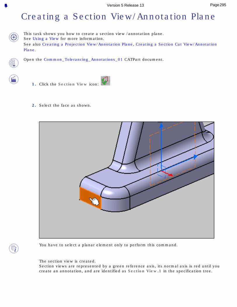
Creating a Section View/Annotation Plane
This task shows you how to create a section view /annotation plane.See Using a View for more information.See also Creating a Projection View/Annotation Plane, Creating a Section Cut View/Annotation Plane.
Open the Common_Tolerancing_Annotations_01 CATPart document.
1. Click the Section View icon:
2. Select the face as shown.
You have to select a planar element only to perform this command.
The section view is created.Section views are represented by a green reference axis, its normal axis is red until you create an annotation, and are identified as Section View.1 in the specification tree.
295Page Functional Tolerancing & Annotation Version 5 Release 13
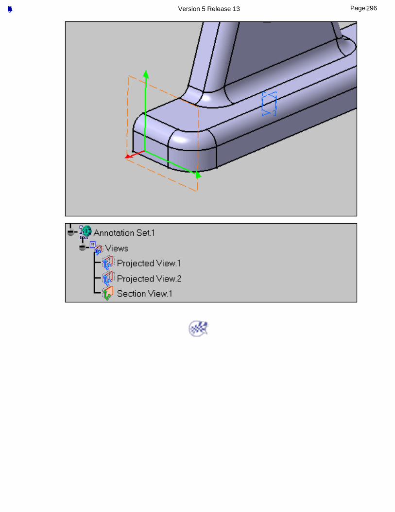
296Page Functional Tolerancing & Annotation Version 5 Release 13

Creating a Section Cut View/Annotation Plane
This task shows you how to create a section cut view /annotation plane.See Using a View for more information.See also Creating a Projection View/Annotation Plane, Creating a Section View/Annotation Plane.
Open the Common_Tolerancing_Annotations_01 CATPart document.
1. Click the Section Cut View icon:
2. Select the face as shown.
You have to select a planar element only to perform this command.
The section cut view is created.Section views are represented by a yellow reference axis, its normal axis is red until you create an annotation, and are identified as Section Cut View.1 in the specification tree.
297Page Functional Tolerancing & Annotation Version 5 Release 13
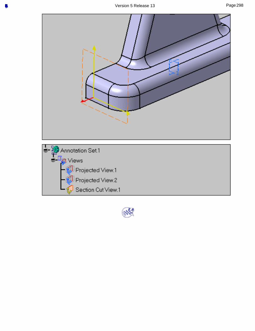
298Page Functional Tolerancing & Annotation Version 5 Release 13
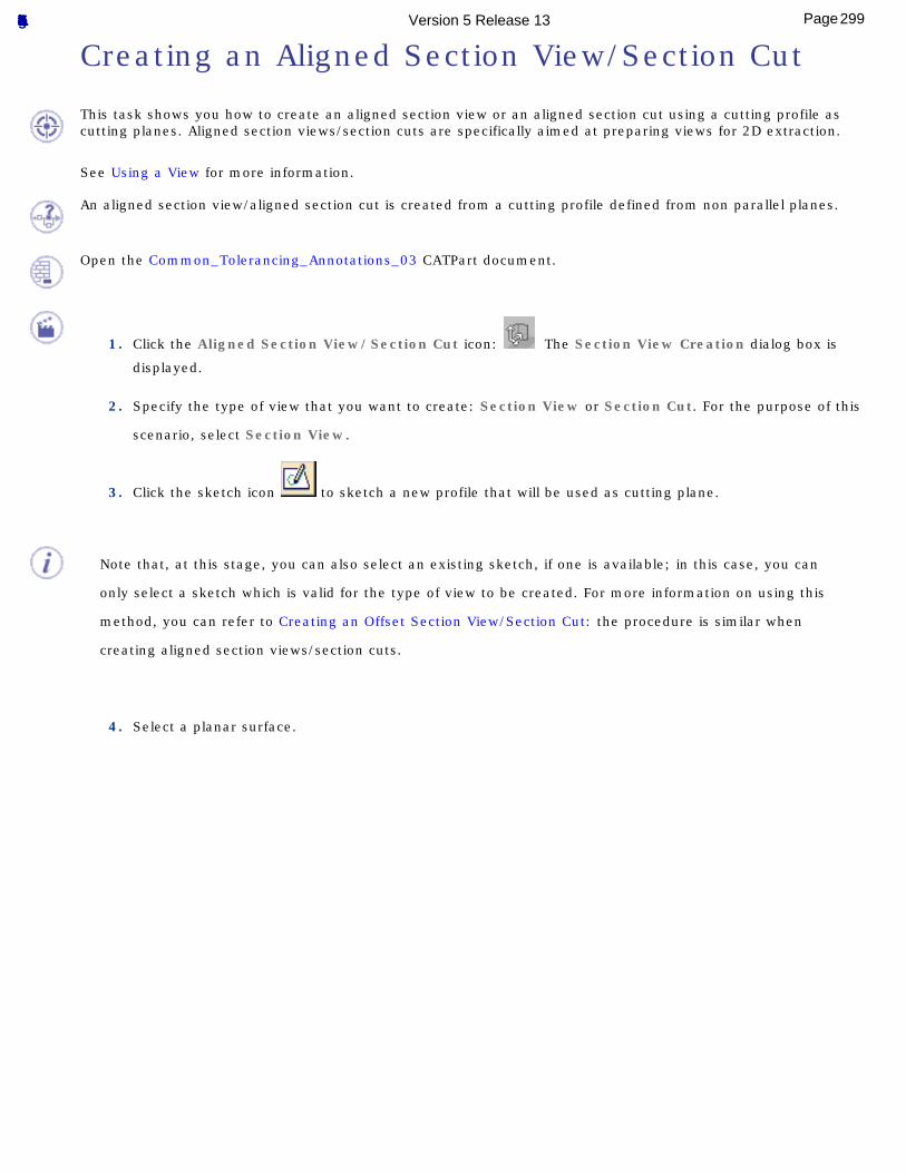
Creating an Aligned Section View/Section Cut
This task shows you how to create an aligned section view or an aligned section cut using a cutting profile as cutting planes. Aligned section views/section cuts are specifically aimed at preparing views for 2D extraction.
See Using a View for more information.
An aligned section view/aligned section cut is created from a cutting profile defined from non parallel planes.
Open the Common_Tolerancing_Annotations_03 CATPart document.
1. Click the Aligned Section View/Section Cut icon: The Section View Creation dialog box is
displayed.
2. Specify the type of view that you want to create: Section View or Section Cut. For the purpose of this
scenario, select Section View.
3. Click the sketch icon to sketch a new profile that will be used as cutting plane.
Note that, at this stage, you can also select an existing sketch, if one is available; in this case, you can
only select a sketch which is valid for the type of view to be created. For more information on using this
method, you can refer to Creating an Offset Section View/Section Cut: the procedure is similar when
creating aligned section views/section cuts.
4. Select a planar surface.
299Page Functional Tolerancing & Annotation Version 5 Release 13
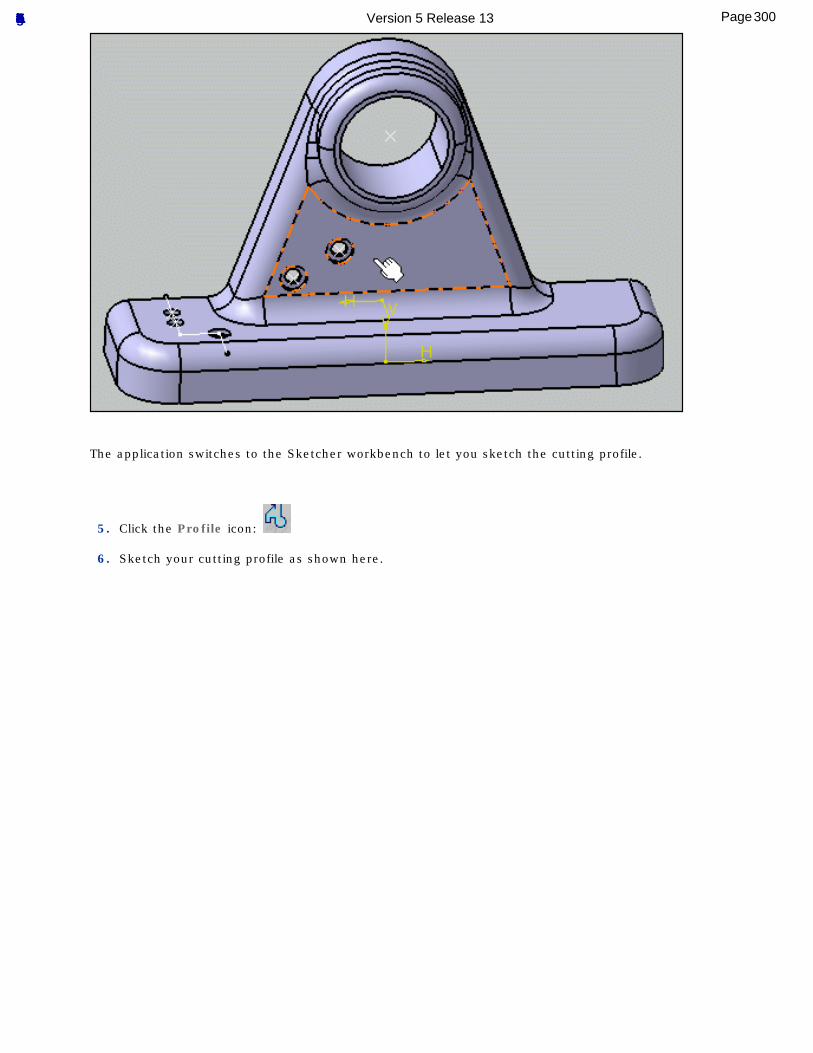
The application switches to the Sketcher workbench to let you sketch the cutting profile.
5. Click the Profile icon:
6. Sketch your cutting profile as shown here.
300Page Functional Tolerancing & Annotation Version 5 Release 13
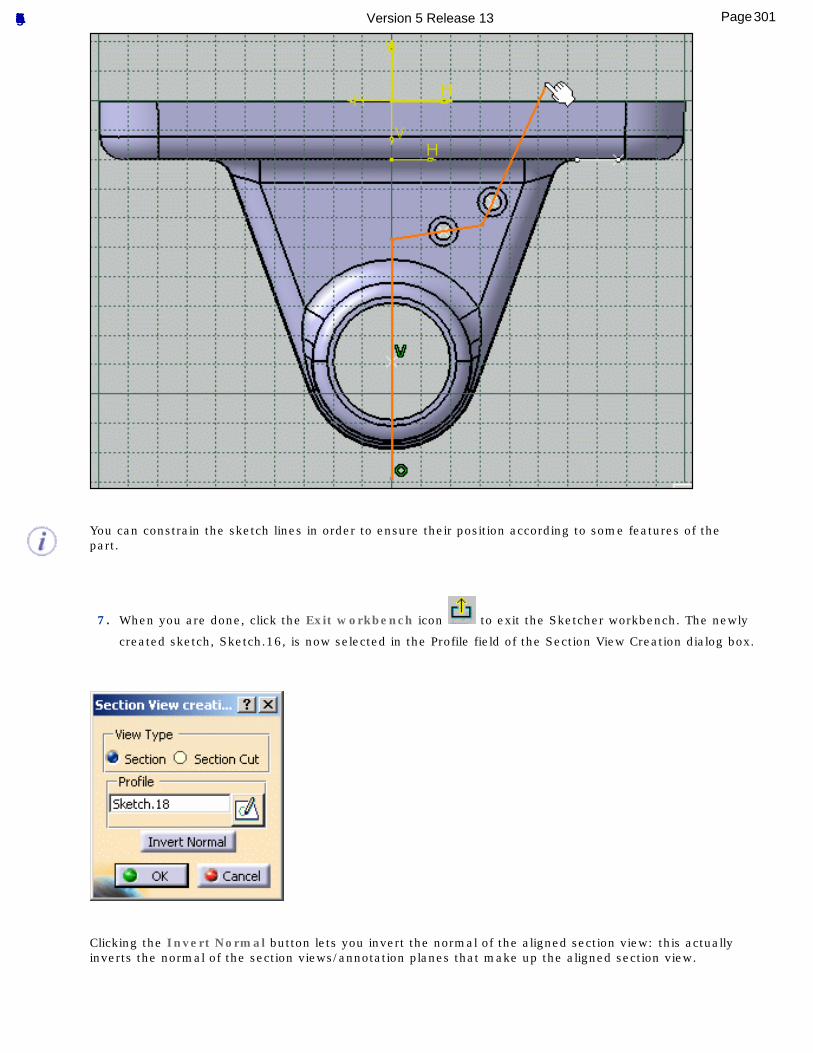
You can constrain the sketch lines in order to ensure their position according to some features of the part.
7. When you are done, click the Exit workbench icon to exit the Sketcher workbench. The newly
created sketch, Sketch.16, is now selected in the Profile field of the Section View Creation dialog box.
Clicking the Invert Normal button lets you invert the normal of the aligned section view: this actually inverts the normal of the section views/annotation planes that make up the aligned section view.
301Page Functional Tolerancing & Annotation Version 5 Release 13
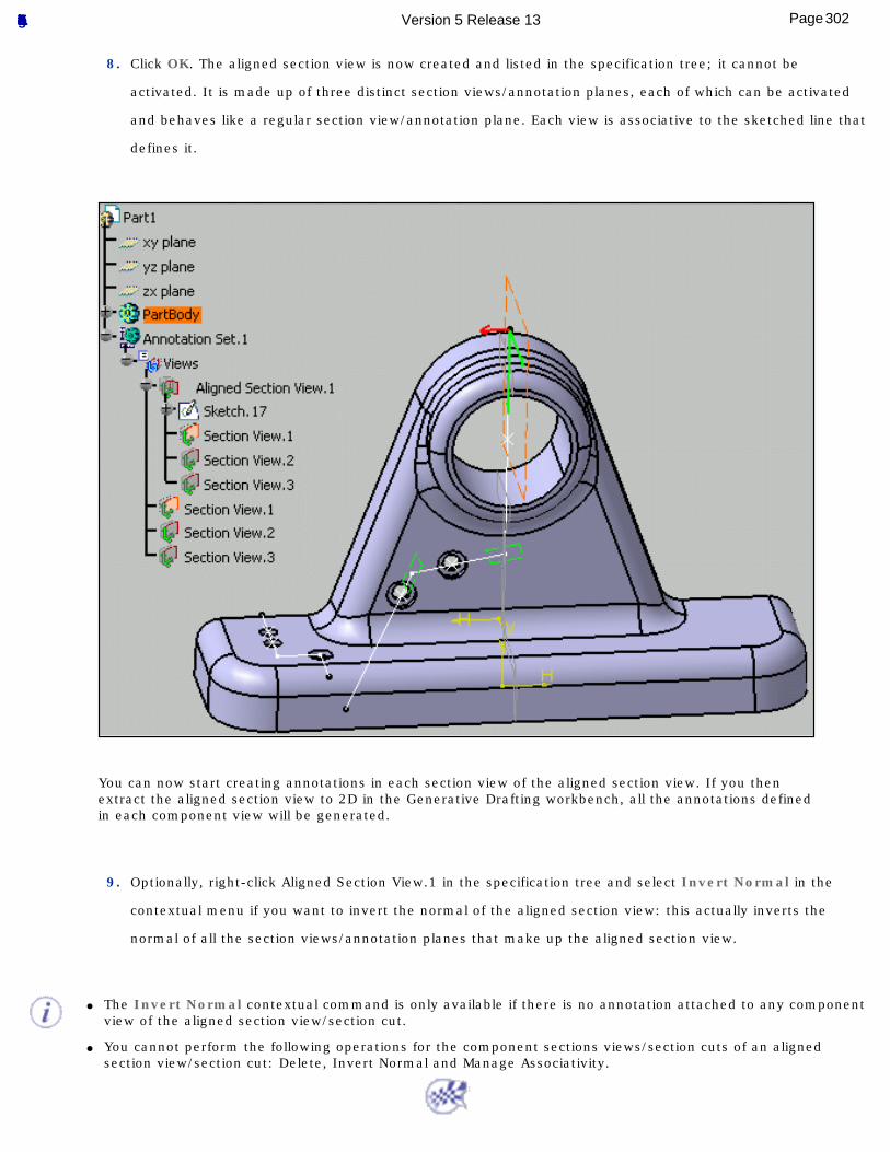
8. Click OK. The aligned section view is now created and listed in the specification tree; it cannot be
activated. It is made up of three distinct section views/annotation planes, each of which can be activated
and behaves like a regular section view/annotation plane. Each view is associative to the sketched line that
defines it.
You can now start creating annotations in each section view of the aligned section view. If you then extract the aligned section view to 2D in the Generative Drafting workbench, all the annotations defined in each component view will be generated.
9. Optionally, right-click Aligned Section View.1 in the specification tree and select Invert Normal in the
contextual menu if you want to invert the normal of the aligned section view: this actually inverts the
normal of all the section views/annotation planes that make up the aligned section view.
● The Invert Normal contextual command is only available if there is no annotation attached to any component view of the aligned section view/section cut.
● You cannot perform the following operations for the component sections views/section cuts of an aligned section view/section cut: Delete, Invert Normal and Manage Associativity.
302Page Functional Tolerancing & Annotation Version 5 Release 13
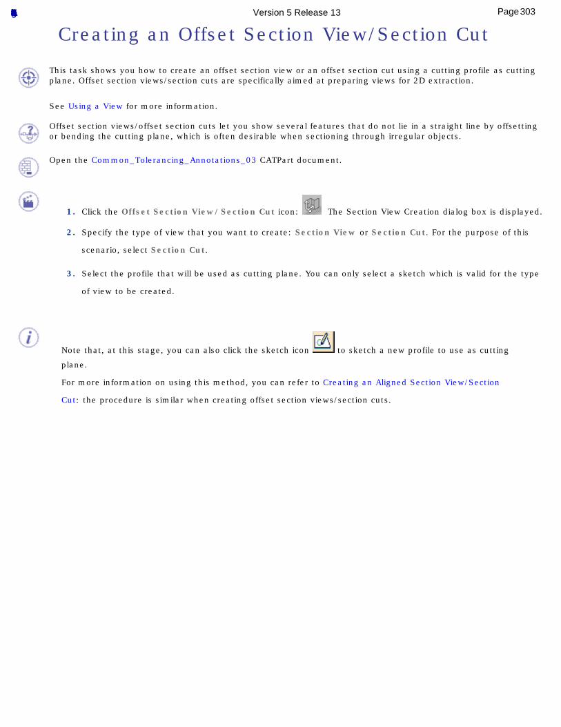
Creating an Offset Section View/Section Cut
This task shows you how to create an offset section view or an offset section cut using a cutting profile as cutting plane. Offset section views/section cuts are specifically aimed at preparing views for 2D extraction.
See Using a View for more information.
Offset section views/offset section cuts let you show several features that do not lie in a straight line by offsetting or bending the cutting plane, which is often desirable when sectioning through irregular objects.
Open the Common_Tolerancing_Annotations_03 CATPart document.
1. Click the Offset Section View/Section Cut icon: The Section View Creation dialog box is displayed.
2. Specify the type of view that you want to create: Section View or Section Cut. For the purpose of this
scenario, select Section Cut.
3. Select the profile that will be used as cutting plane. You can only select a sketch which is valid for the type
of view to be created.
Note that, at this stage, you can also click the sketch icon to sketch a new profile to use as cutting
plane.
For more information on using this method, you can refer to Creating an Aligned Section View/Section
Cut: the procedure is similar when creating offset section views/section cuts.
303Page Functional Tolerancing & Annotation Version 5 Release 13
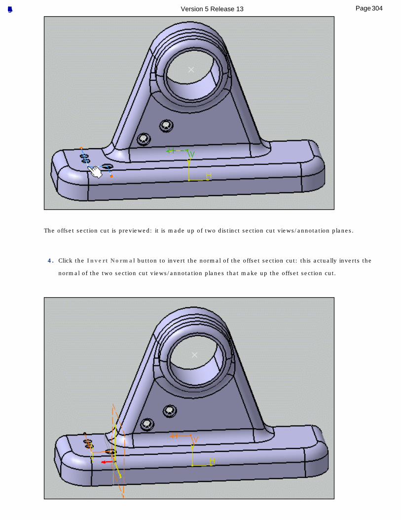
The offset section cut is previewed: it is made up of two distinct section cut views/annotation planes.
4. Click the Invert Normal button to invert the normal of the offset section cut: this actually inverts the
normal of the two section cut views/annotation planes that make up the offset section cut.
304Page Functional Tolerancing & Annotation Version 5 Release 13
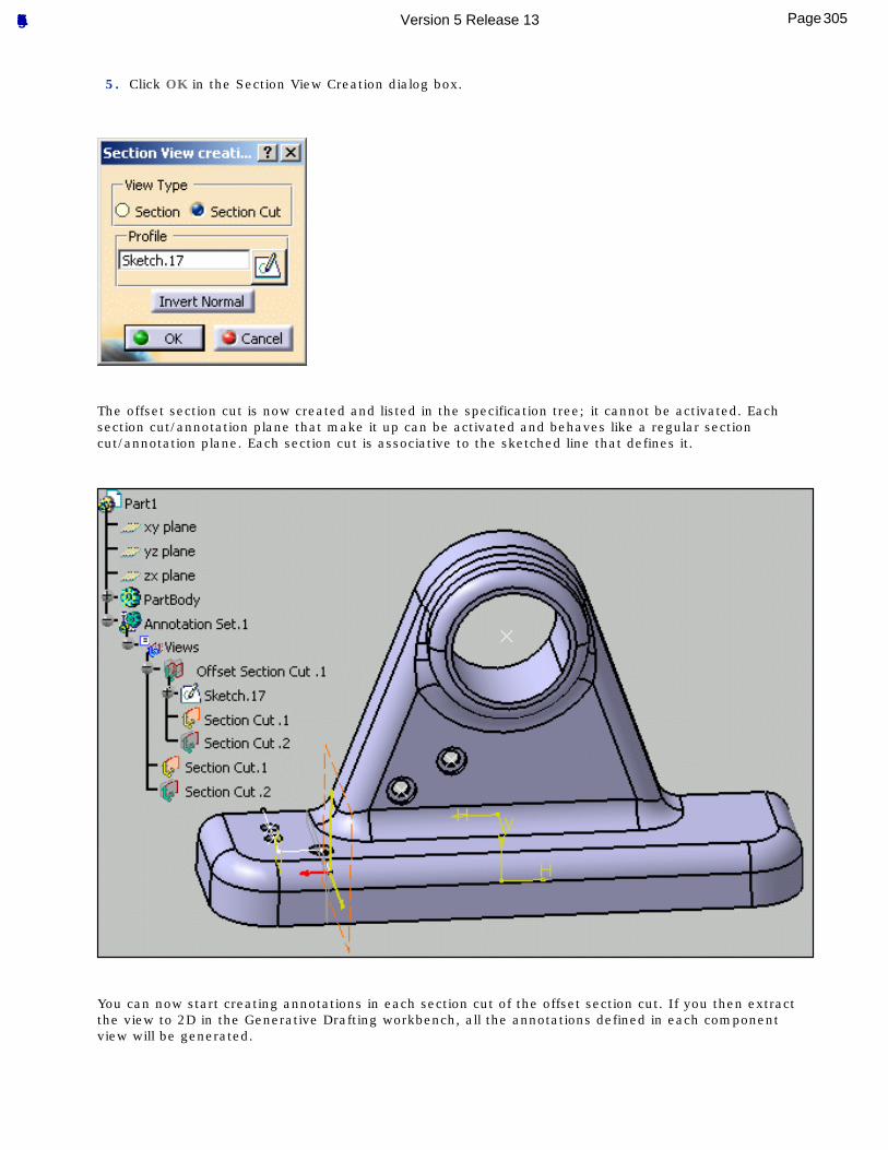
5. Click OK in the Section View Creation dialog box.
The offset section cut is now created and listed in the specification tree; it cannot be activated. Each section cut/annotation plane that make it up can be activated and behaves like a regular section cut/annotation plane. Each section cut is associative to the sketched line that defines it.
You can now start creating annotations in each section cut of the offset section cut. If you then extract the view to 2D in the Generative Drafting workbench, all the annotations defined in each component view will be generated.
305Page Functional Tolerancing & Annotation Version 5 Release 13
6. Optionally, right-click Offset Section Cut.1 in the specification tree and select Invert Normal in the
contextual menu if you want to invert the normal of the offset section cut: this actually inverts the normal
of all the section cuts/annotation planes that make up the offset section cut.
You cannot perform the following operations for the component section views/section cuts of an offset section view/section cut: Delete, Invert Normal and Manage Associativity.
306Page Functional Tolerancing & Annotation Version 5 Release 13
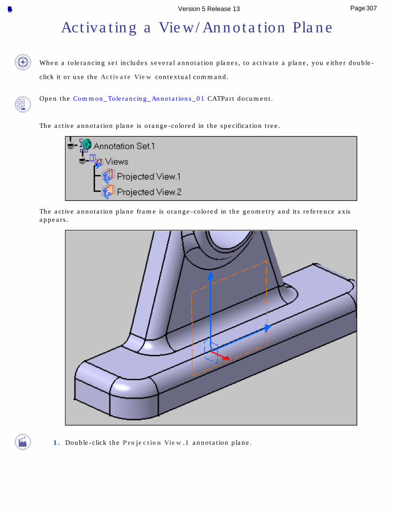
Activating a View/Annotation Plane
When a tolerancing set includes several annotation planes, to activate a plane, you either double-
click it or use the Activate View contextual command.
Open the Common_Tolerancing_Annotations_01 CATPart document.
The active annotation plane is orange-colored in the specification tree.
The active annotation plane frame is orange-colored in the geometry and its reference axis appears.
1. Double-click the Projection View.1 annotation plane.
307Page Functional Tolerancing & Annotation Version 5 Release 13
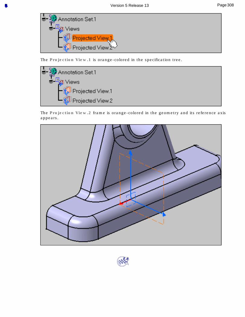
The Projection View.1 is orange-colored in the specification tree.
The Projection View.2 frame is orange-colored in the geometry and its reference axis appears.
308Page Functional Tolerancing & Annotation Version 5 Release 13
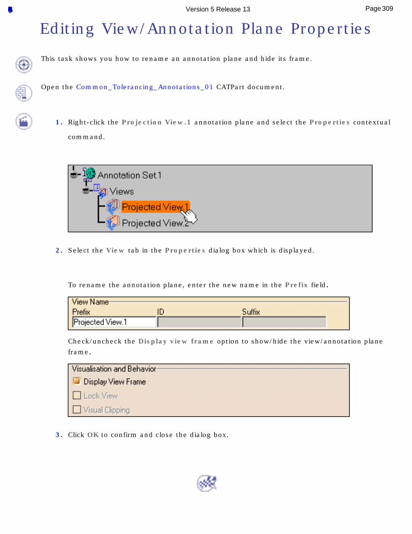
Editing View/Annotation Plane Properties
This task shows you how to rename an annotation plane and hide its frame.
Open the Common_Tolerancing_Annotations_01 CATPart document.
1. Right-click the Projection View.1 annotation plane and select the Properties contextual
command.
2. Select the View tab in the Properties dialog box which is displayed.
To rename the annotation plane, enter the new name in the Prefix field.
Check/uncheck the Display view frame option to show/hide the view/annotation plane
frame.
3. Click OK to confirm and close the dialog box.
309Page Functional Tolerancing & Annotation Version 5 Release 13
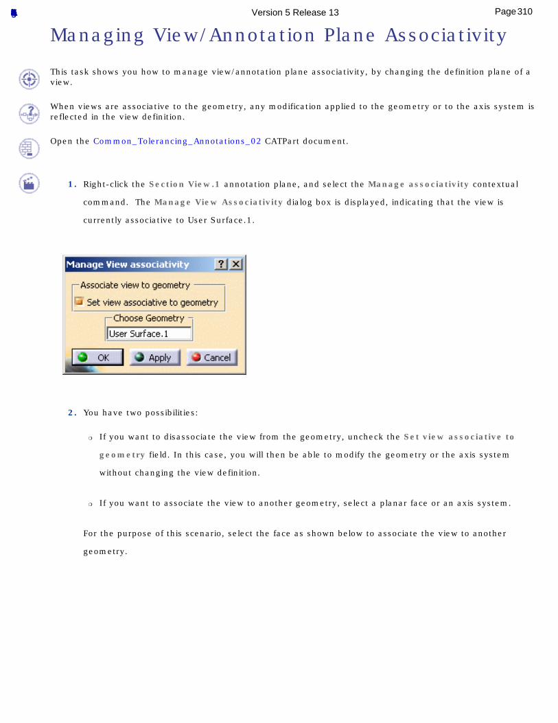
Managing View/Annotation Plane Associativity
This task shows you how to manage view/annotation plane associativity, by changing the definition plane of a view.
When views are associative to the geometry, any modification applied to the geometry or to the axis system is reflected in the view definition.
Open the Common_Tolerancing_Annotations_02 CATPart document.
1. Right-click the Section View.1 annotation plane, and select the Manage associativity contextual
command. The Manage View Associativity dialog box is displayed, indicating that the view is
currently associative to User Surface.1.
2. You have two possibilities:
❍ If you want to disassociate the view from the geometry, uncheck the Set view associative to
geometry field. In this case, you will then be able to modify the geometry or the axis system
without changing the view definition.
❍ If you want to associate the view to another geometry, select a planar face or an axis system.
For the purpose of this scenario, select the face as shown below to associate the view to another
geometry.
310Page Functional Tolerancing & Annotation Version 5 Release 13
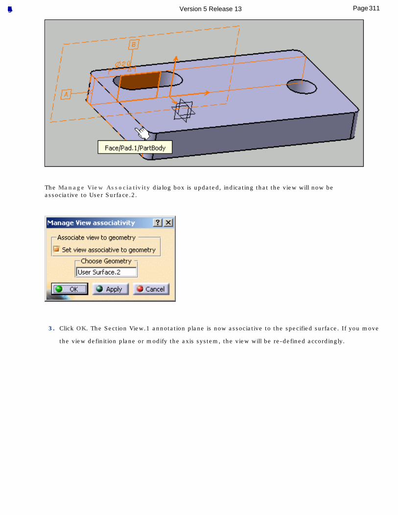
The Manage View Associativity dialog box is updated, indicating that the view will now be associative to User Surface.2.
3. Click OK. The Section View.1 annotation plane is now associative to the specified surface. If you move
the view definition plane or modify the axis system, the view will be re-defined accordingly.
311Page Functional Tolerancing & Annotation Version 5 Release 13
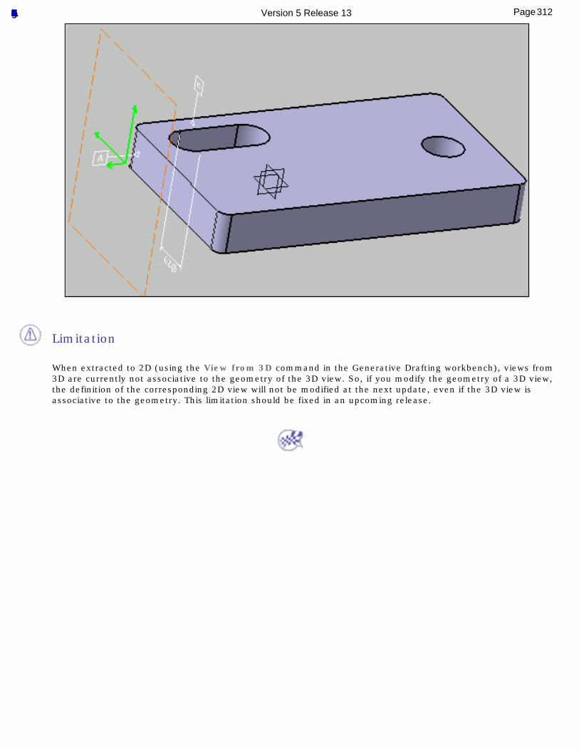
Limitation
When extracted to 2D (using the View from 3D command in the Generative Drafting workbench), views from 3D are currently not associative to the geometry of the 3D view. So, if you modify the geometry of a 3D view, the definition of the corresponding 2D view will not be modified at the next update, even if the 3D view is associative to the geometry. This limitation should be fixed in an upcoming release.
312Page Functional Tolerancing & Annotation Version 5 Release 13
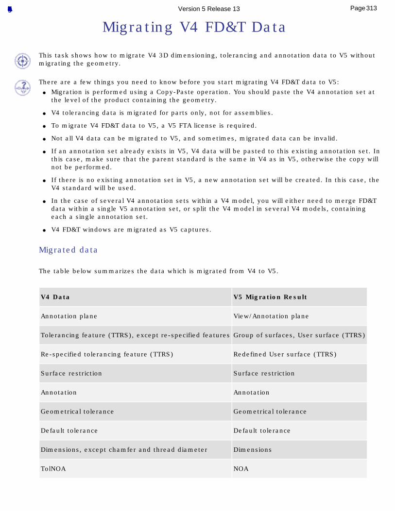
Migrating V4 FD&T Data
This task shows how to migrate V4 3D dimensioning, tolerancing and annotation data to V5 without migrating the geometry.
There are a few things you need to know before you start migrating V4 FD&T data to V5:● Migration is performed using a Copy-Paste operation. You should paste the V4 annotation set at
the level of the product containing the geometry.
● V4 tolerancing data is migrated for parts only, not for assemblies.
● To migrate V4 FD&T data to V5, a V5 FTA license is required.
● Not all V4 data can be migrated to V5, and sometimes, migrated data can be invalid.
● If an annotation set already exists in V5, V4 data will be pasted to this existing annotation set. In this case, make sure that the parent standard is the same in V4 as in V5, otherwise the copy will not be performed.
● If there is no existing annotation set in V5, a new annotation set will be created. In this case, the V4 standard will be used.
● In the case of several V4 annotation sets within a V4 model, you will either need to merge FD&T data within a single V5 annotation set, or split the V4 model in several V4 models, containing each a single annotation set.
● V4 FD&T windows are migrated as V5 captures.
Migrated data
The table below summarizes the data which is migrated from V4 to V5.
V4 Data V5 Migration Result
Annotation plane View/Annotation plane
Tolerancing feature (TTRS), except re-specified features Group of surfaces, User surface (TTRS)
Re-specified tolerancing feature (TTRS) Redefined User surface (TTRS)
Surface restriction Surface restriction
Annotation Annotation
Geometrical tolerance Geometrical tolerance
Default tolerance Default tolerance
Dimensions, except chamfer and thread diameter Dimensions
TolNOA NOA
313Page Functional Tolerancing & Annotation Version 5 Release 13
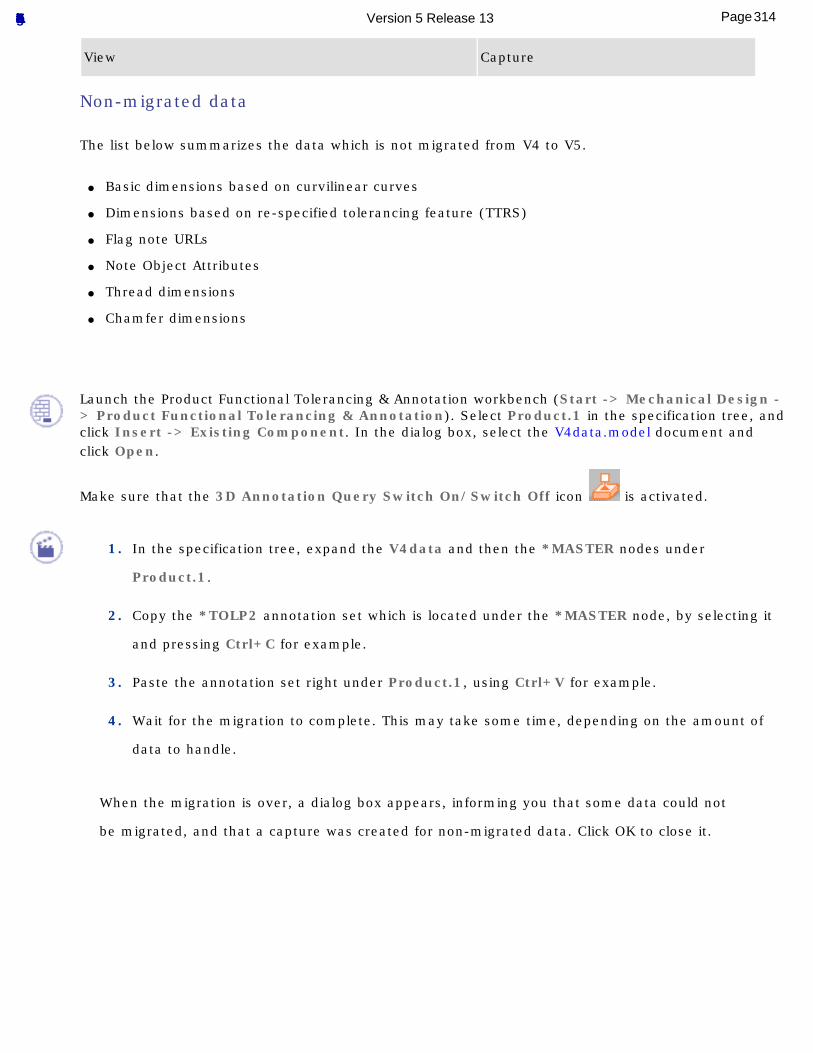
View Capture
Non-migrated data
The list below summarizes the data which is not migrated from V4 to V5.
● Basic dimensions based on curvilinear curves
● Dimensions based on re-specified tolerancing feature (TTRS)
● Flag note URLs
● Note Object Attributes
● Thread dimensions
● Chamfer dimensions
Launch the Product Functional Tolerancing & Annotation workbench (Start -> Mechanical Design -> Product Functional Tolerancing & Annotation). Select Product.1 in the specification tree, and click Insert -> Existing Component. In the dialog box, select the V4data.model document and click Open.
Make sure that the 3D Annotation Query Switch On/Switch Off icon is activated.
1. In the specification tree, expand the V4data and then the *MASTER nodes under
Product.1.
2. Copy the *TOLP2 annotation set which is located under the *MASTER node, by selecting it
and pressing Ctrl+C for example.
3. Paste the annotation set right under Product.1, using Ctrl+V for example.
4. Wait for the migration to complete. This may take some time, depending on the amount of
data to handle.
When the migration is over, a dialog box appears, informing you that some data could not
be migrated, and that a capture was created for non-migrated data. Click OK to close it.
314Page Functional Tolerancing & Annotation Version 5 Release 13
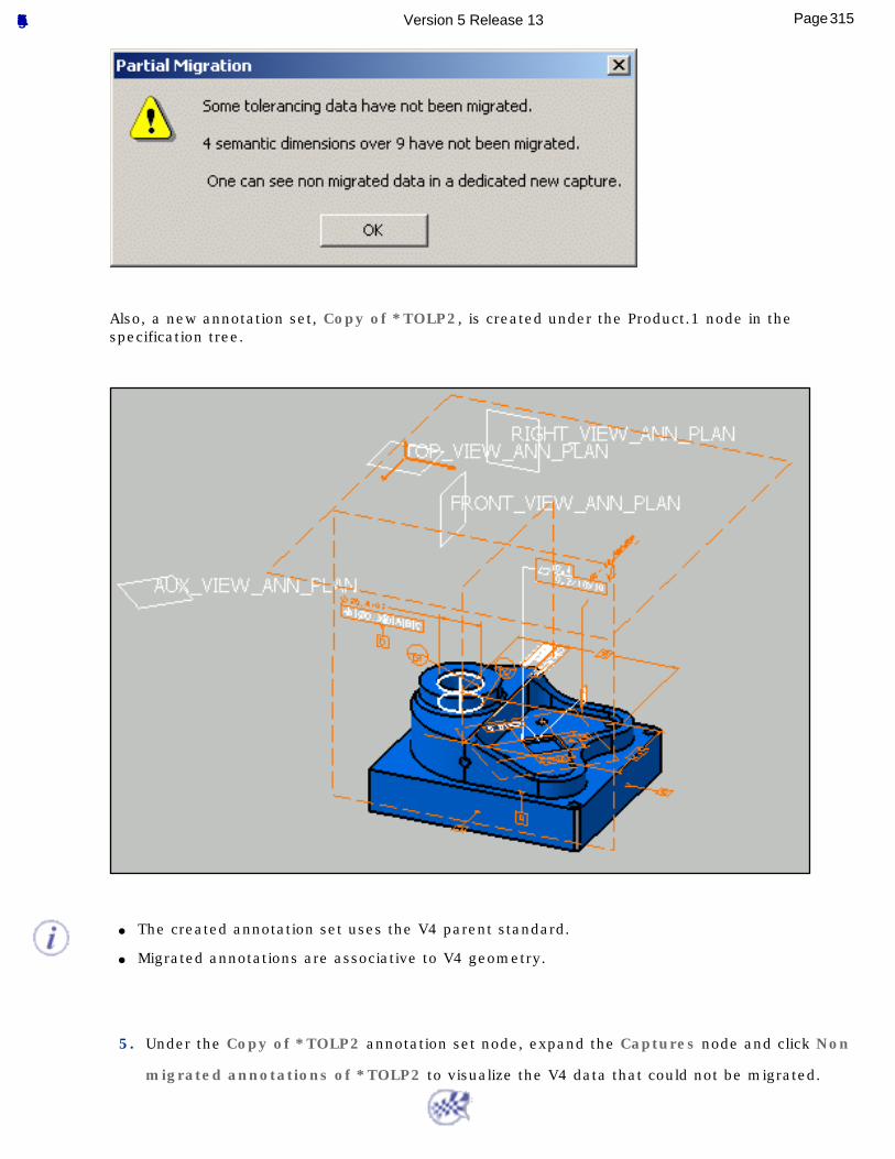
Also, a new annotation set, Copy of *TOLP2, is created under the Product.1 node in the specification tree.
● The created annotation set uses the V4 parent standard.
● Migrated annotations are associative to V4 geometry.
5. Under the Copy of *TOLP2 annotation set node, expand the Captures node and click Non
migrated annotations of *TOLP2 to visualize the V4 data that could not be migrated.
315Page Functional Tolerancing & Annotation Version 5 Release 13
Advanced Tasks3D Functional Tolerancing & Annotation allows you to perform the following advanced tasks:
Creating Note Object AttributeManaging Annotation Connection
Re-specifying Geometry CanonicityReporting Annotations
Annotation AssociativityManaging Power Copies
Providing Constructed Geometry for 3D Annotations
316Page Functional Tolerancing & Annotation Version 5 Release 13
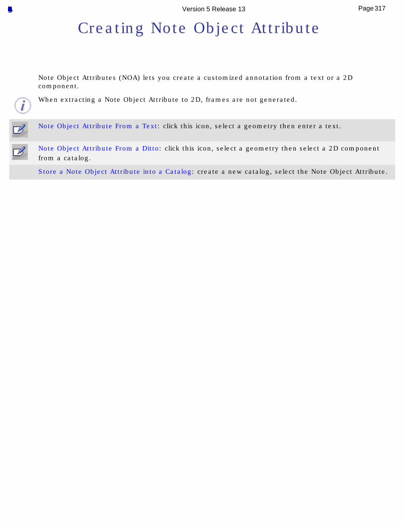
Creating Note Object Attribute
Note Object Attributes (NOA) lets you create a customized annotation from a text or a 2D component.
When extracting a Note Object Attribute to 2D, frames are not generated.
Note Object Attribute From a Text: click this icon, select a geometry then enter a text.
Note Object Attribute From a Ditto: click this icon, select a geometry then select a 2D component from a catalog.
Store a Note Object Attribute into a Catalog: create a new catalog, select the Note Object Attribute.
317Page Functional Tolerancing & Annotation Version 5 Release 13
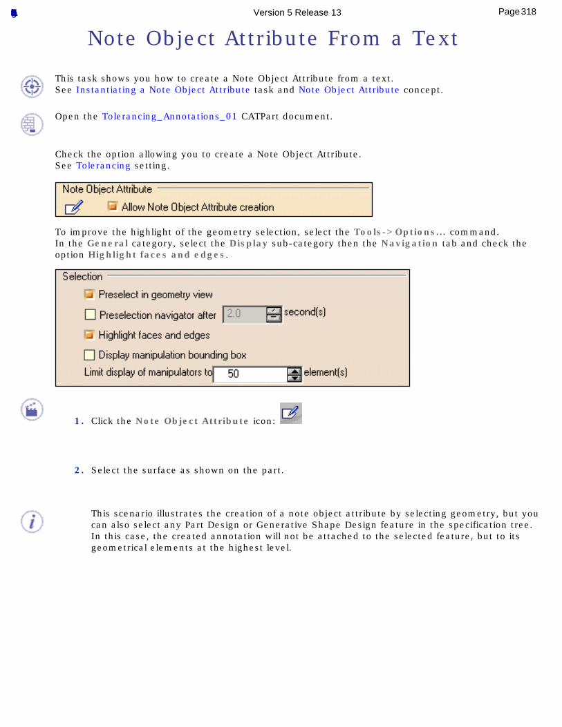
Note Object Attribute From a Text
This task shows you how to create a Note Object Attribute from a text.See Instantiating a Note Object Attribute task and Note Object Attribute concept.
Open the Tolerancing_Annotations_01 CATPart document.
Check the option allowing you to create a Note Object Attribute.See Tolerancing setting.
To improve the highlight of the geometry selection, select the Tools->Options... command.In the General category, select the Display sub-category then the Navigation tab and check the option Highlight faces and edges.
1. Click the Note Object Attribute icon:
2. Select the surface as shown on the part.
This scenario illustrates the creation of a note object attribute by selecting geometry, but you can also select any Part Design or Generative Shape Design feature in the specification tree. In this case, the created annotation will not be attached to the selected feature, but to its geometrical elements at the highest level.
318Page Functional Tolerancing & Annotation Version 5 Release 13
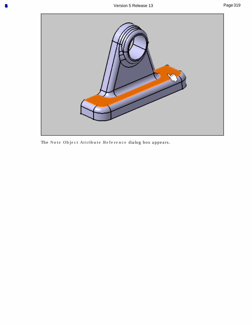
The Note Object Attribute Reference dialog box appears.
319Page Functional Tolerancing & Annotation Version 5 Release 13
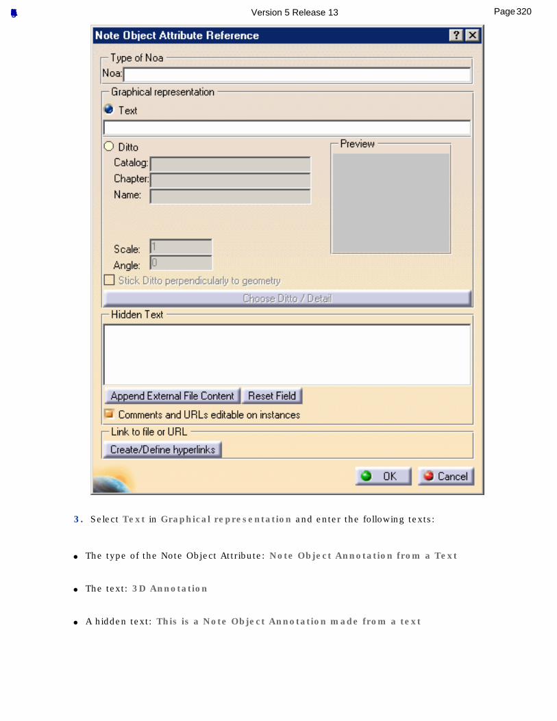
3. Select Text in Graphical representation and enter the following texts:
● The type of the Note Object Attribute: Note Object Annotation from a Text
● The text: 3D Annotation
● A hidden text: This is a Note Object Annotation made from a text
320Page Functional Tolerancing & Annotation Version 5 Release 13
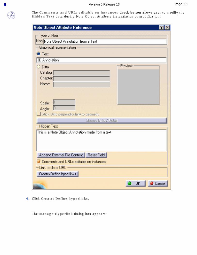
The Comments and URLs editable on instances check button allows user to modify the Hidden Text data during Note Object Attribute instantiation or modification.
4. Click Create/Define hyperlinks.
The Manage Hyperlink dialog box appears.
321Page Functional Tolerancing & Annotation Version 5 Release 13
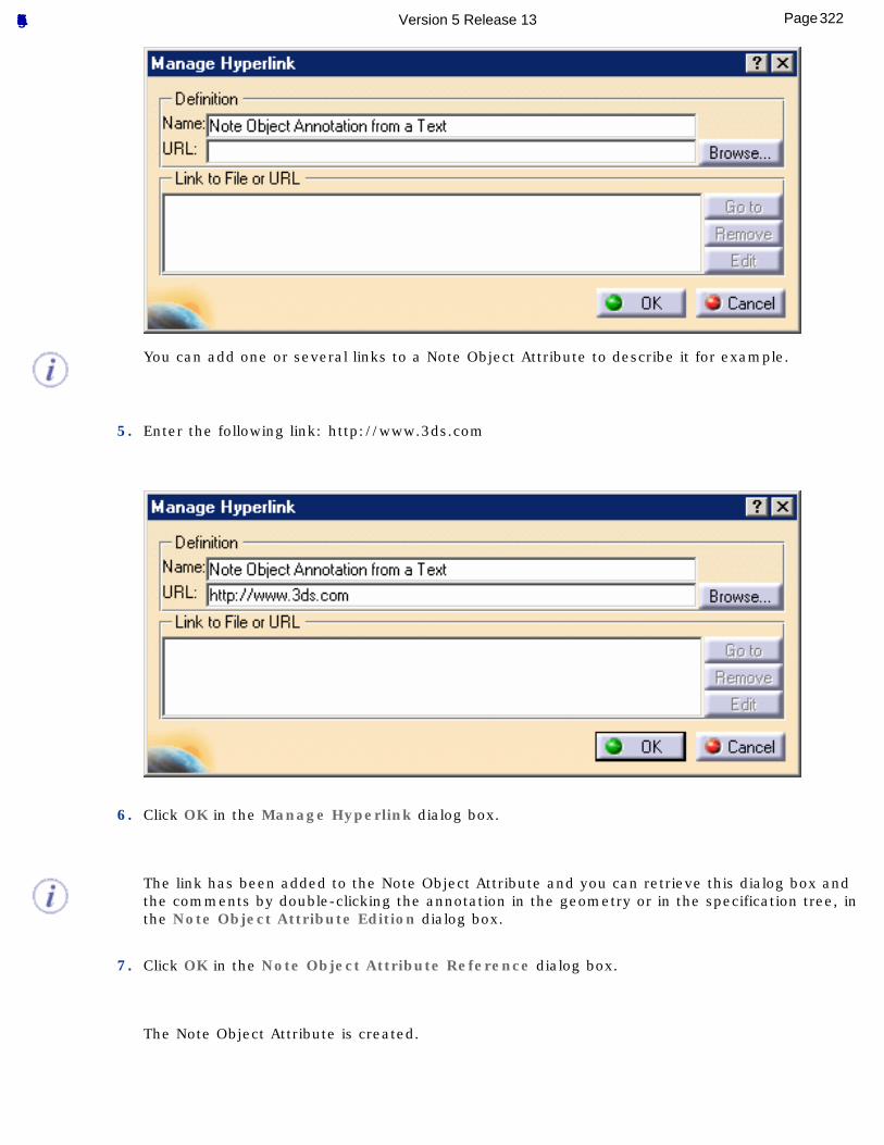
You can add one or several links to a Note Object Attribute to describe it for example.
5. Enter the following link: http://www.3ds.com
6. Click OK in the Manage Hyperlink dialog box.
The link has been added to the Note Object Attribute and you can retrieve this dialog box and the comments by double-clicking the annotation in the geometry or in the specification tree, in the Note Object Attribute Edition dialog box.
7. Click OK in the Note Object Attribute Reference dialog box.
The Note Object Attribute is created.
322Page Functional Tolerancing & Annotation Version 5 Release 13
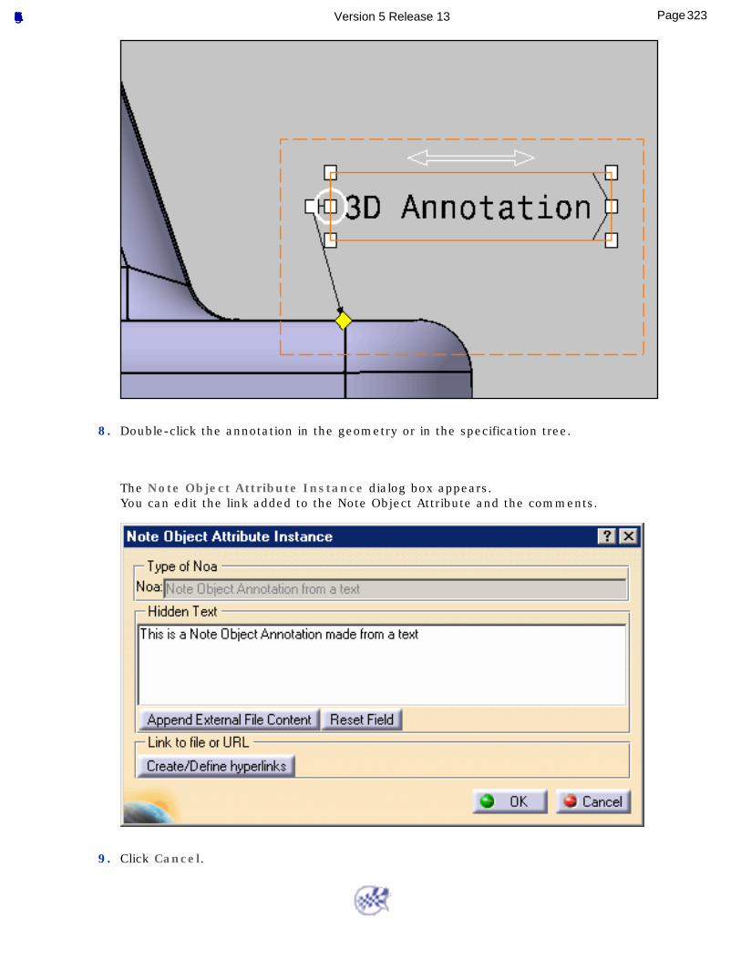
8. Double-click the annotation in the geometry or in the specification tree.
The Note Object Attribute Instance dialog box appears.You can edit the link added to the Note Object Attribute and the comments.
9. Click Cancel.
323Page Functional Tolerancing & Annotation Version 5 Release 13
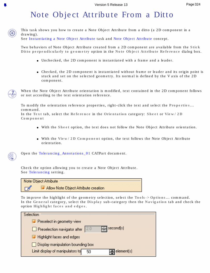
Note Object Attribute From a Ditto
This task shows you how to create a Note Object Attribute from a ditto (a 2D component in a drawing).See Instantiating a Note Object Attribute task and Note Object Attribute concept.
Two behaviors of Note Object Attribute created from a 2D component are available from the Stick Ditto perpendicularly to geometry option in the Note Object Attribute Reference dialog box.
● Unchecked, the 2D component is instantiated with a frame and a leader.
● Checked, the 2D component is instantiated without frame or leader and its origin point is
stuck and set on the selected geometry. Its normal is defined by the V axis of the 2D component.
When the Note Object Attribute orientation is modified, text contained in the 2D component follows or not according to the text orientation reference.
To modify the orientation reference properties, right-click the text and select the Properties... command.In the Text tab, select the Reference in the Orientation category: Sheet or View/2D Component
● With the Sheet option, the text does not follow the Note Object Attribute orientation.
● With the View/2D Component option, the text follows the Note Object Attribute
orientation.
Open the Tolerancing_Annotations_01 CATPart document.
Check the option allowing you to create a Note Object Attribute.See Tolerancing setting.
To improve the highlight of the geometry selection, select the Tools->Options... command.In the General category, select the Display sub-category then the Navigation tab and check the option Highlight faces and edges.
324Page Functional Tolerancing & Annotation Version 5 Release 13
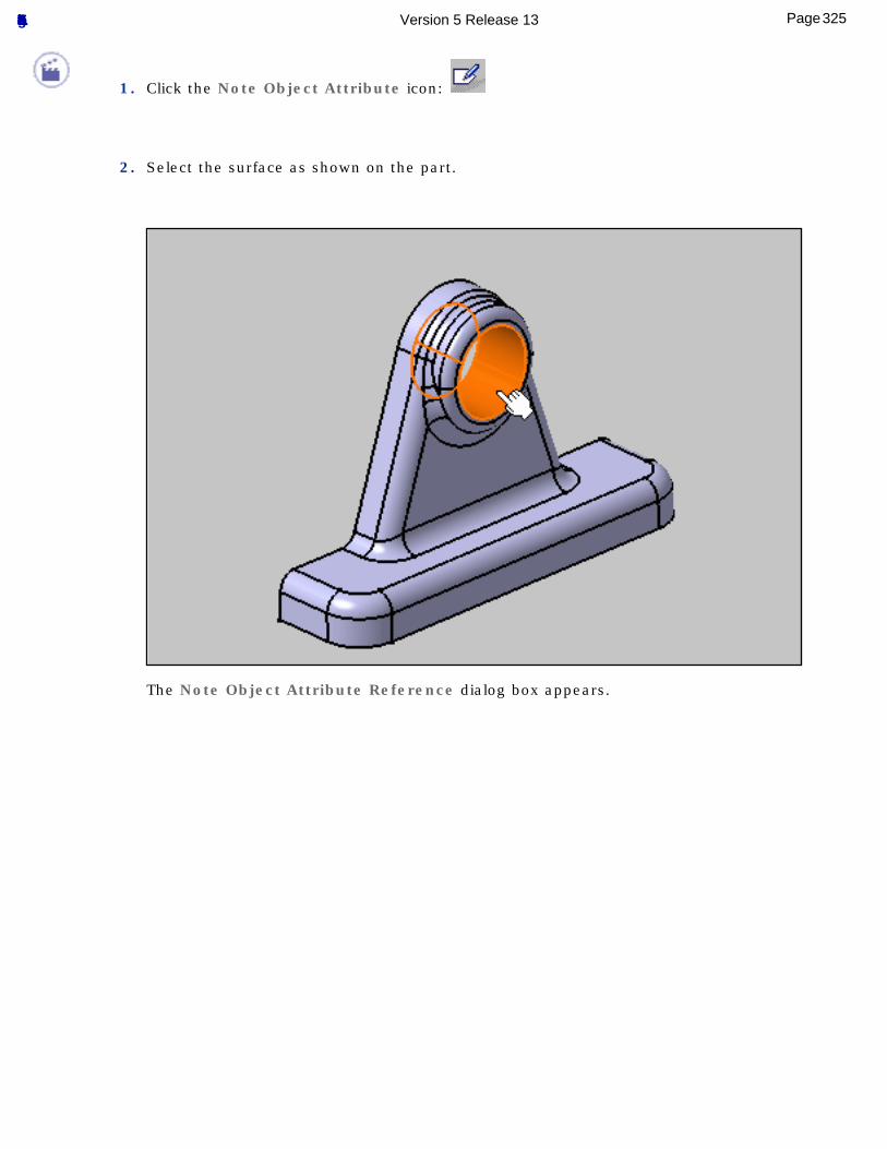
1. Click the Note Object Attribute icon:
2. Select the surface as shown on the part.
The Note Object Attribute Reference dialog box appears.
325Page Functional Tolerancing & Annotation Version 5 Release 13
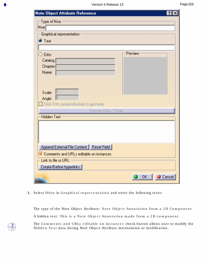
3. Select Ditto in Graphical representation and enter the following texts:
The type of the Note Object Attribute: Note Object Annotation from a 2D Component
A hidden text: This is a Note Object Annotation made from a 2D component
The Comments and URLs editable on instances check button allows user to modify the Hidden Text data during Note Object Attribute instantiation or modification.
326Page Functional Tolerancing & Annotation Version 5 Release 13
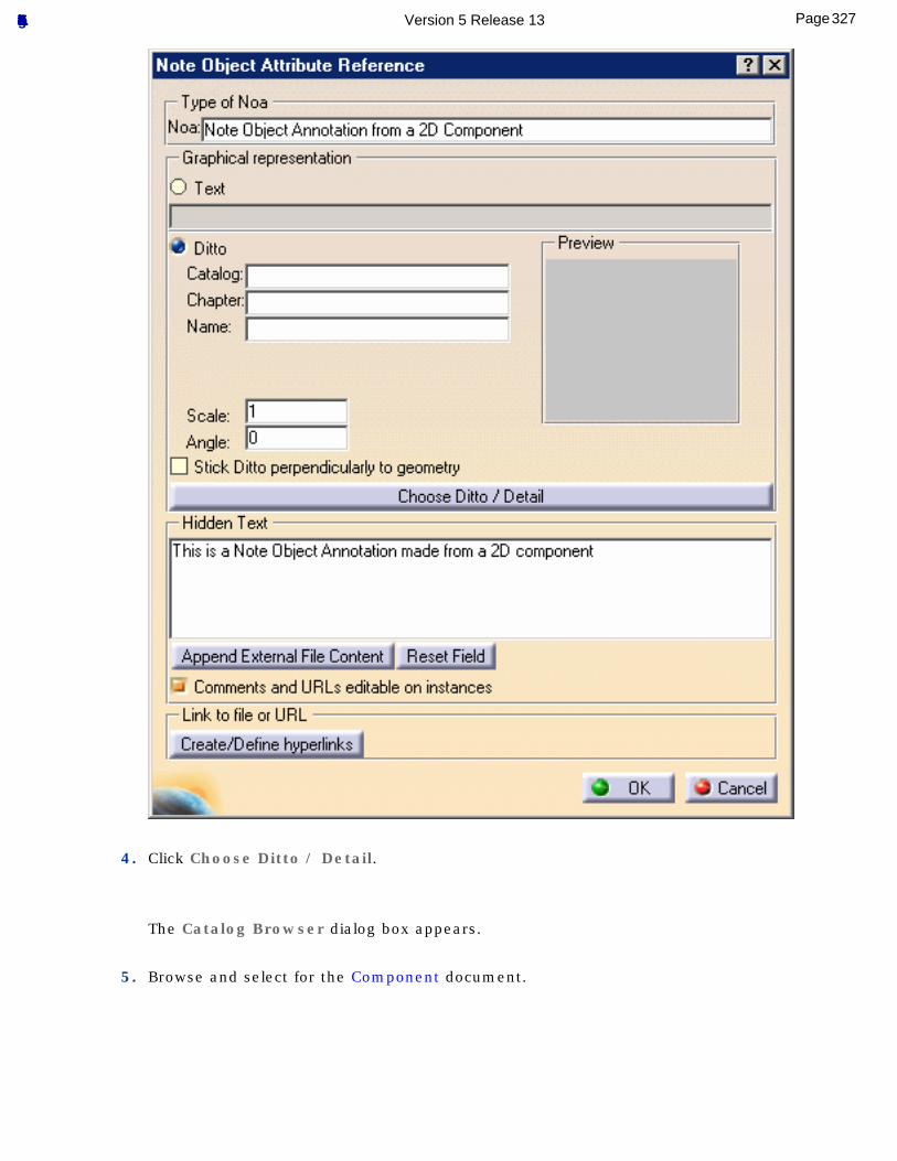
4. Click Choose Ditto / Detail.
The Catalog Browser dialog box appears.
5. Browse and select for the Component document.
327Page Functional Tolerancing & Annotation Version 5 Release 13
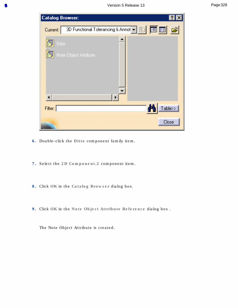
6. Double-click the Ditto component family item.
7. Select the 2D Component.2 component item.
8. Click OK in the Catalog Browser dialog box.
9. Click OK in the Note Object Attribute Reference dialog box .
The Note Object Attribute is created.
328Page Functional Tolerancing & Annotation Version 5 Release 13
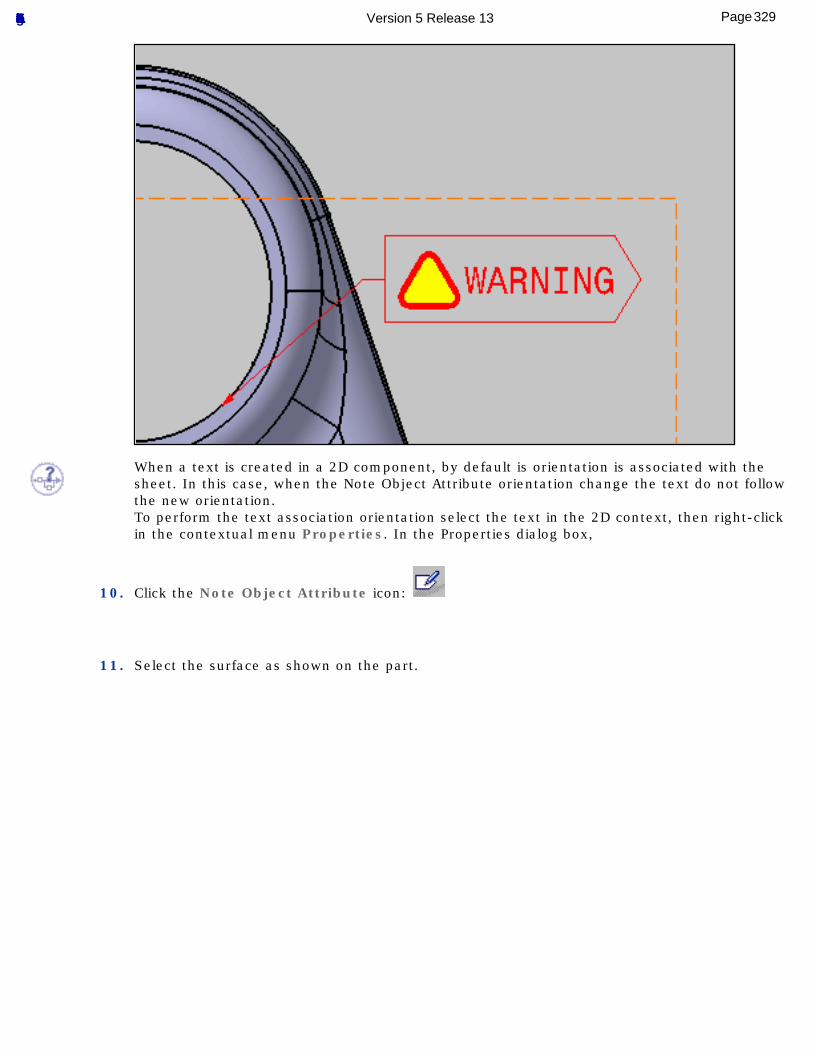
When a text is created in a 2D component, by default is orientation is associated with the sheet. In this case, when the Note Object Attribute orientation change the text do not follow the new orientation.To perform the text association orientation select the text in the 2D context, then right-click in the contextual menu Properties. In the Properties dialog box,
10. Click the Note Object Attribute icon:
11. Select the surface as shown on the part.
329Page Functional Tolerancing & Annotation Version 5 Release 13
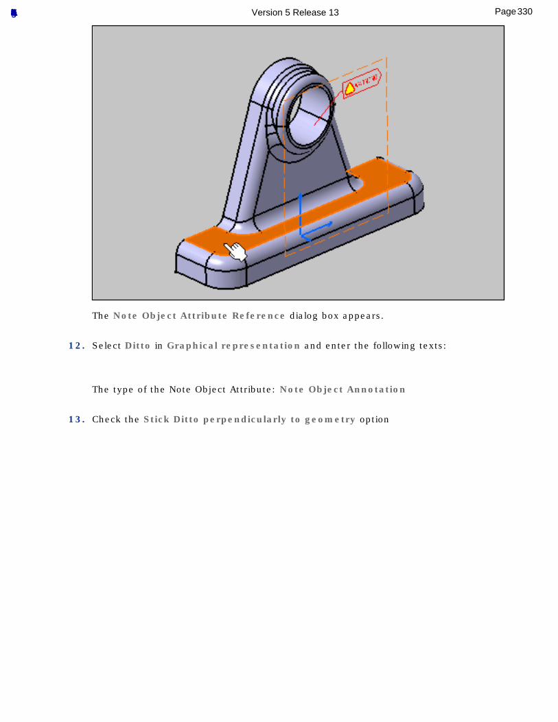
The Note Object Attribute Reference dialog box appears.
12. Select Ditto in Graphical representation and enter the following texts:
The type of the Note Object Attribute: Note Object Annotation
13. Check the Stick Ditto perpendicularly to geometry option
330Page Functional Tolerancing & Annotation Version 5 Release 13
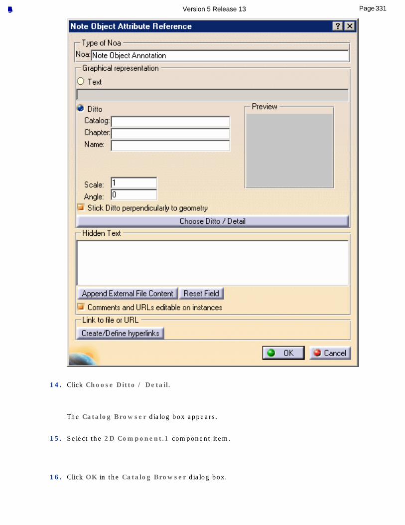
14. Click Choose Ditto / Detail.
The Catalog Browser dialog box appears.
15. Select the 2D Component.1 component item.
16. Click OK in the Catalog Browser dialog box.
331Page Functional Tolerancing & Annotation Version 5 Release 13
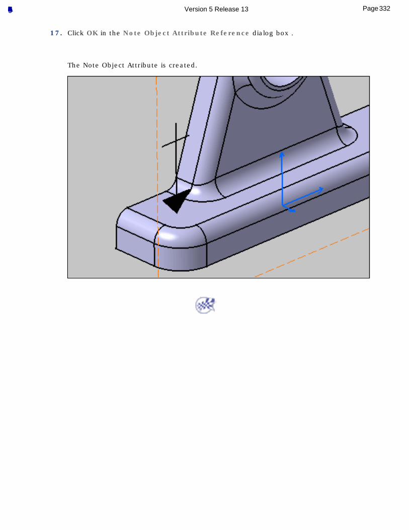
17. Click OK in the Note Object Attribute Reference dialog box .
The Note Object Attribute is created.
332Page Functional Tolerancing & Annotation Version 5 Release 13
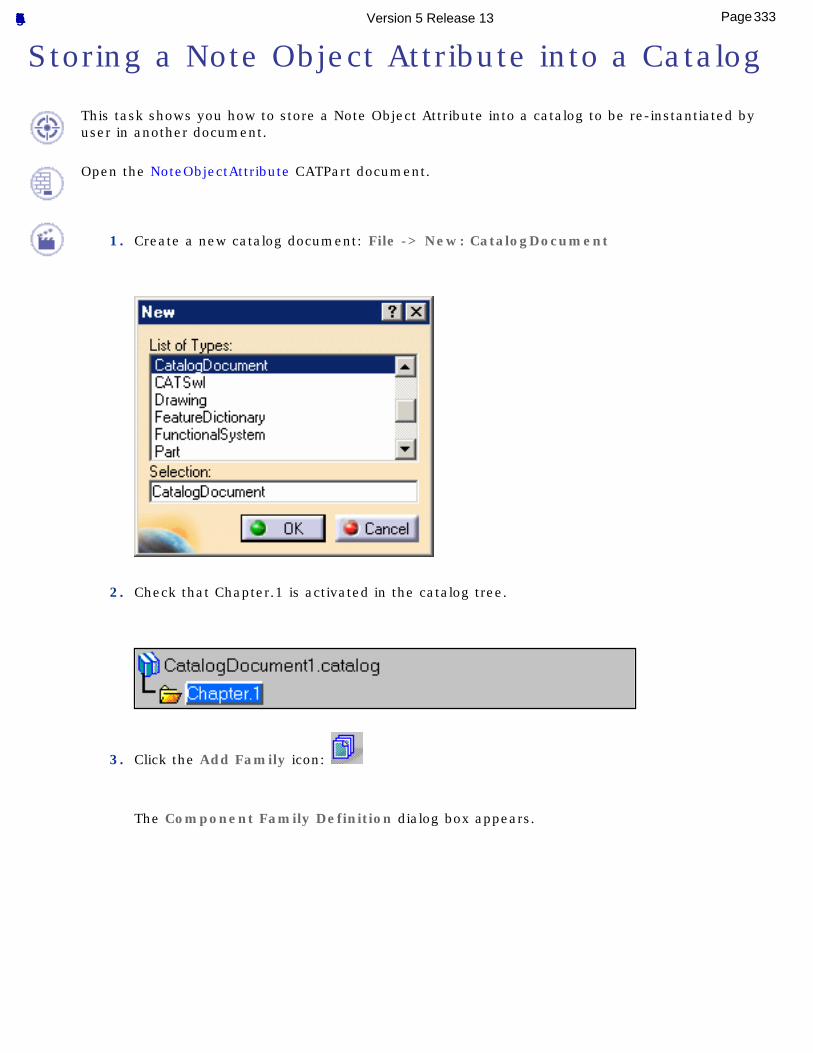
Storing a Note Object Attribute into a Catalog
This task shows you how to store a Note Object Attribute into a catalog to be re-instantiated by user in another document.
Open the NoteObjectAttribute CATPart document.
1. Create a new catalog document: File -> New: CatalogDocument
2. Check that Chapter.1 is activated in the catalog tree.
3. Click the Add Family icon:
The Component Family Definition dialog box appears.
333Page Functional Tolerancing & Annotation Version 5 Release 13
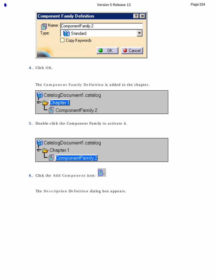
4. Click OK.
The Component Family Definition is added to the chapter.
5. Double-click the Component Family to activate it.
6. Click the Add Component icon:
The Description Definition dialog box appears.
334Page Functional Tolerancing & Annotation Version 5 Release 13
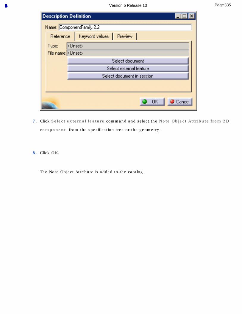
7. Click Select external feature command and select the Note Object Attribute from 2D
component from the specification tree or the geometry.
8. Click OK.
The Note Object Attribute is added to the catalog.
335Page Functional Tolerancing & Annotation Version 5 Release 13
336Page Functional Tolerancing & Annotation Version 5 Release 13
Managing Annotation Connection
Manage annotation connection offers to create, delete, modify or rename geometrical elements or user surfaces of an existing annotation:
Use the Scope Range: select the Geometry Connection Management command and select an annotation.
Add Geometry: select the Geometry Connection Management command and select an annotation.
Add Component: select the Geometry Connection Management command and select an annotation.
337Page Functional Tolerancing & Annotation Version 5 Release 13
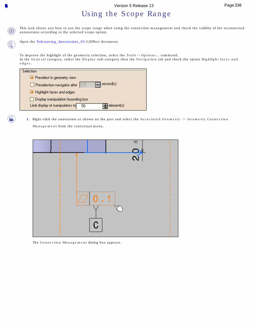
Using the Scope Range
This task shows you how to use the scope range when using the connection management and check the validity of the reconnected annotations according to the selected scope option.
Open the Tolerancing_Annotations_03 CATPart document.
To improve the highlight of the geometry selection, select the Tools->Options... command.In the General category, select the Display sub-category then the Navigation tab and check the option Highlight faces and edges.
1. Right-click the annotation as shown on the part and select the Associated Geometry -> Geometry Connection
Management from the contextual menu.
The Connection Management dialog box appears.
338Page Functional Tolerancing & Annotation Version 5 Release 13
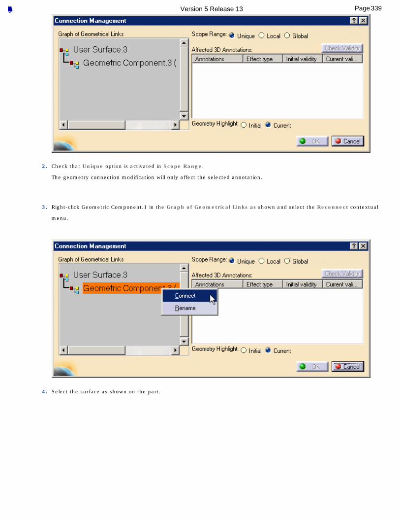
2. Check that Unique option is activated in Scope Range.
The geometry connection modification will only affect the selected annotation.
3. Right-click Geometric Component.1 in the Graph of Geometrical Links as shown and select the Reconnect contextual
menu.
4. Select the surface as shown on the part.
339Page Functional Tolerancing & Annotation Version 5 Release 13
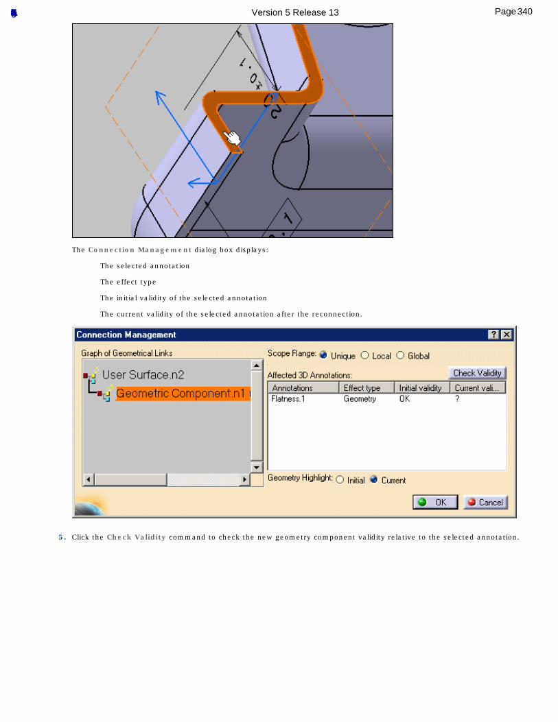
The Connection Management dialog box displays:
The selected annotation
The effect type
The initial validity of the selected annotation
The current validity of the selected annotation after the reconnection.
5. Click the Check Validity command to check the new geometry component validity relative to the selected annotation.
340Page Functional Tolerancing & Annotation Version 5 Release 13
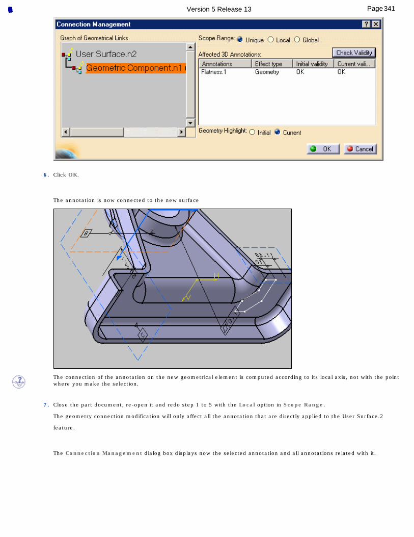
6. Click OK.
The annotation is now connected to the new surface
The connection of the annotation on the new geometrical element is computed according to its local axis, not with the point where you make the selection.
7. Close the part document, re-open it and redo step 1 to 5 with the Local option in Scope Range.
The geometry connection modification will only affect all the annotation that are directly applied to the User Surface.2
feature.
The Connection Management dialog box displays now the selected annotation and all annotations related with it.
341Page Functional Tolerancing & Annotation Version 5 Release 13
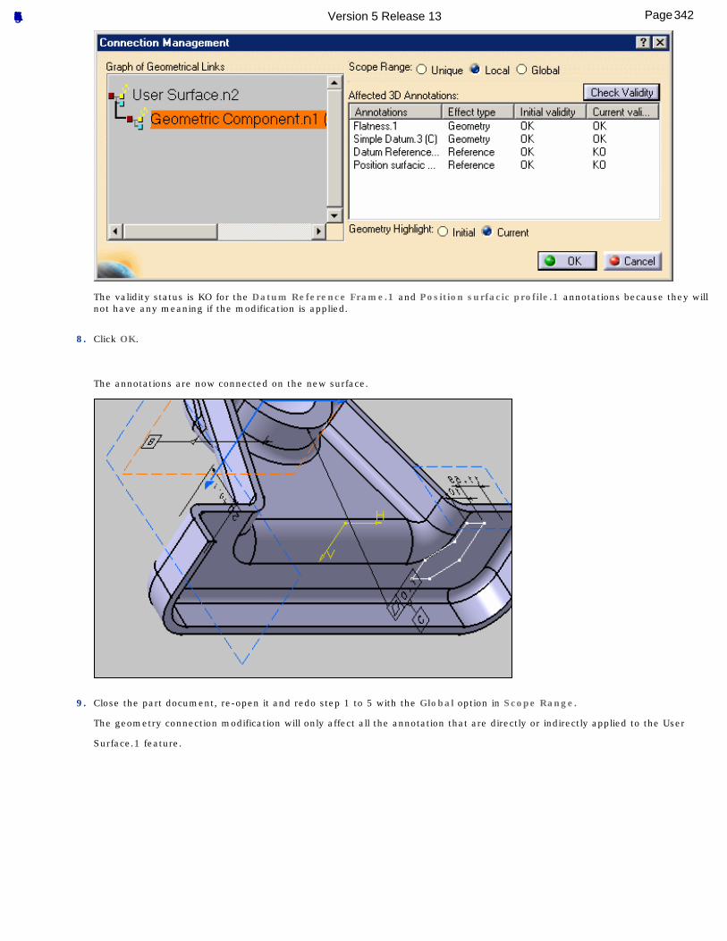
The validity status is KO for the Datum Reference Frame.1 and Position surfacic profile.1 annotations because they will not have any meaning if the modification is applied.
8. Click OK.
The annotations are now connected on the new surface.
9. Close the part document, re-open it and redo step 1 to 5 with the Global option in Scope Range.
The geometry connection modification will only affect all the annotation that are directly or indirectly applied to the User
Surface.1 feature.
342Page Functional Tolerancing & Annotation Version 5 Release 13
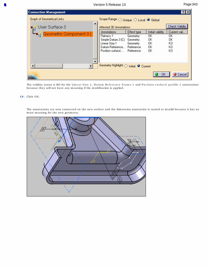
The validity status is KO for the Linear Size.1, Datum Reference Frame.1 and Position surfacic profile.1 annotations because they will not have any meaning if the modification is applied.
10. Click OK.
The annotations are now connected on the new surface and the dimension annotation is turned to invalid because it has no more meaning for the new geometry.
343Page Functional Tolerancing & Annotation Version 5 Release 13
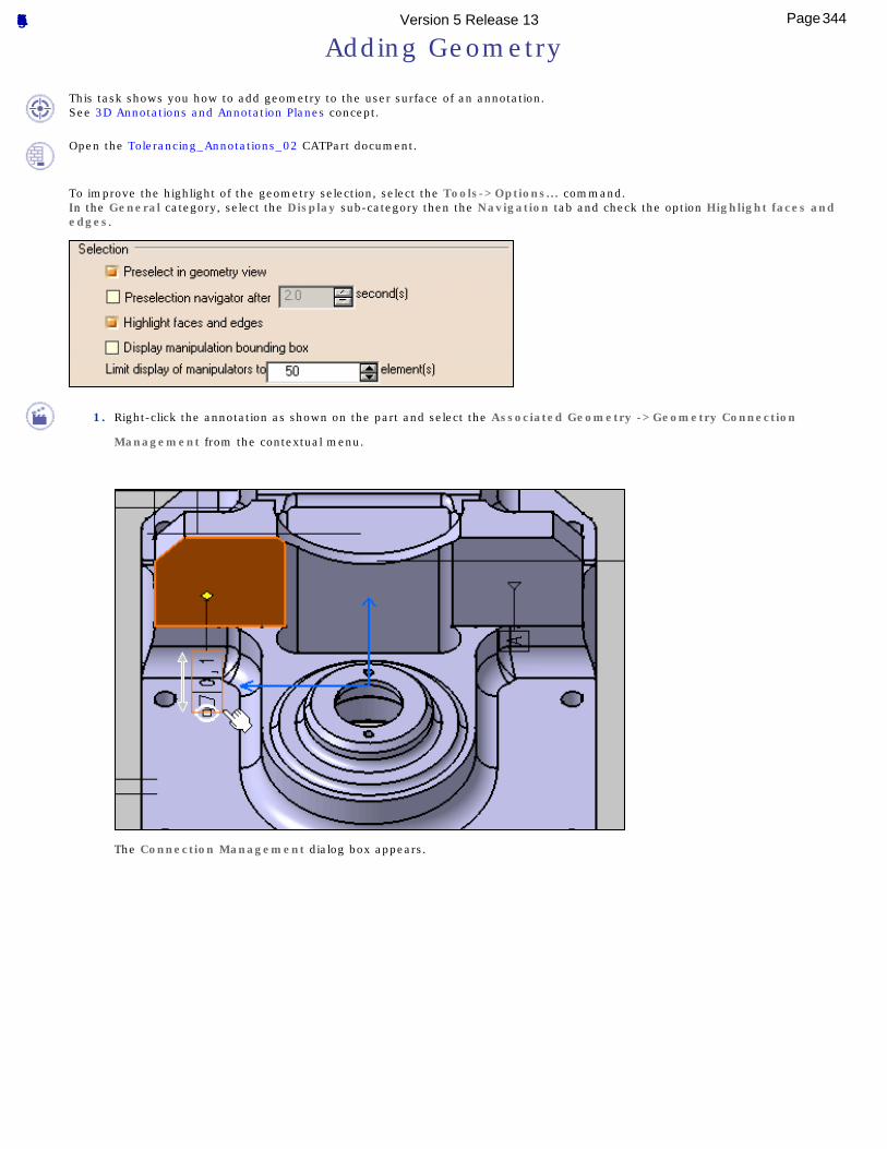
Adding Geometry
This task shows you how to add geometry to the user surface of an annotation.See 3D Annotations and Annotation Planes concept.
Open the Tolerancing_Annotations_02 CATPart document.
To improve the highlight of the geometry selection, select the Tools->Options... command.In the General category, select the Display sub-category then the Navigation tab and check the option Highlight faces and edges.
1. Right-click the annotation as shown on the part and select the Associated Geometry ->Geometry Connection
Management from the contextual menu.
The Connection Management dialog box appears.
344Page Functional Tolerancing & Annotation Version 5 Release 13
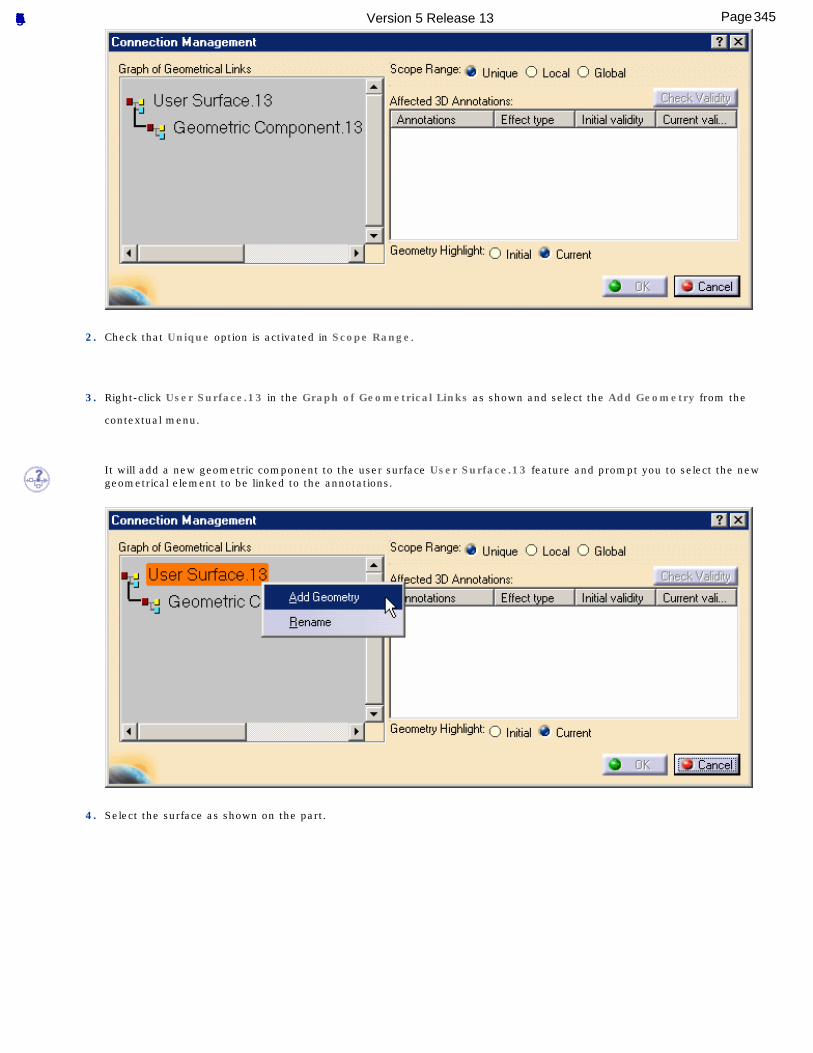
2. Check that Unique option is activated in Scope Range.
3. Right-click User Surface.13 in the Graph of Geometrical Links as shown and select the Add Geometry from the
contextual menu.
It will add a new geometric component to the user surface User Surface.13 feature and prompt you to select the new geometrical element to be linked to the annotations.
4. Select the surface as shown on the part.
345Page Functional Tolerancing & Annotation Version 5 Release 13
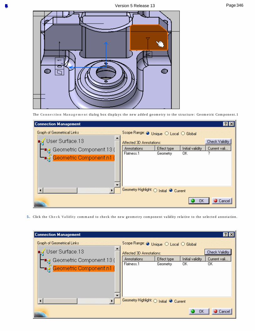
The Connection Management dialog box displays the new added geometry to the structure: Geometric Component.1
5. Click the Check Validity command to check the new geometry component validity relative to the selected annotation.
346Page Functional Tolerancing & Annotation Version 5 Release 13

6. Click OK.
The two geometric components are now link to the annotation.
7. Right-click the annotation again and select the Geometry Connection Management contextual menu.
8. Right-click Geometric Component.2 in the Graph of Geometrical Links as shown and select the Delete contextual
menu.
9. Click the Check Validity
The Connection Management dialog box displays the updated structure.
347Page Functional Tolerancing & Annotation Version 5 Release 13
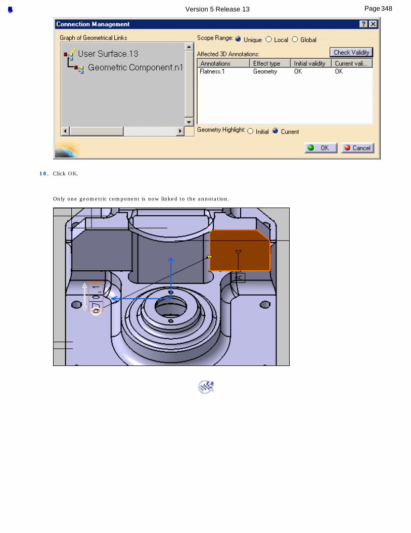
10. Click OK.
Only one geometric component is now linked to the annotation.
348Page Functional Tolerancing & Annotation Version 5 Release 13
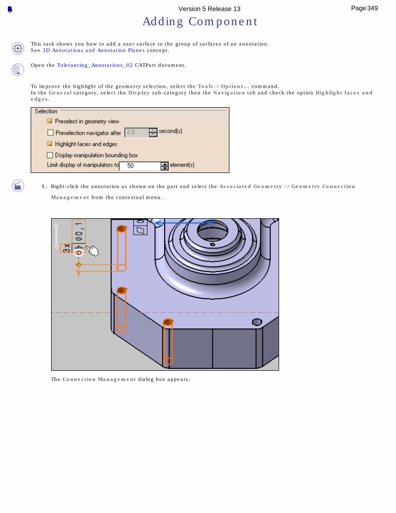
Adding Component
This task shows you how to add a user surface to the group of surfaces of an annotation.See 3D Annotations and Annotation Planes concept.
Open the Tolerancing_Annotations_02 CATPart document.
To improve the highlight of the geometry selection, select the Tools->Options... command.In the General category, select the Display sub-category then the Navigation tab and check the option Highlight faces and edges.
1. Right-click the annotation as shown on the part and select the Associated Geometry ->Geometry Connection
Management from the contextual menu.
The Connection Management dialog box appears.
349Page Functional Tolerancing & Annotation Version 5 Release 13
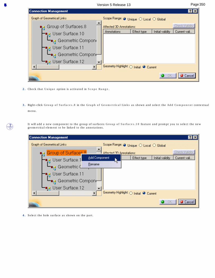
2. Check that Unique option is activated in Scope Range.
3. Right-click Group of Surfaces.8 in the Graph of Geometrical Links as shown and select the Add Component contextual
menu.
It will add a new component to the group of surfaces Group of Surfaces.10 feature and prompt you to select the new geometrical element to be linked to the annotations.
4. Select the hole surface as shown on the part.
350Page Functional Tolerancing & Annotation Version 5 Release 13
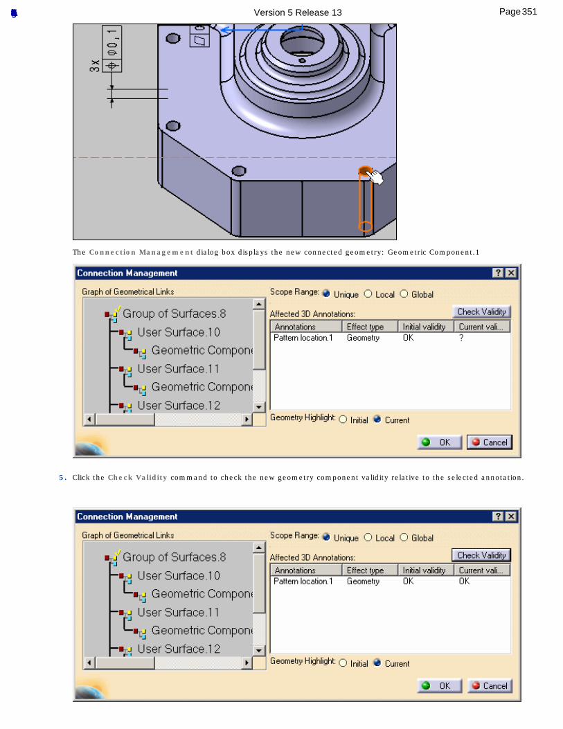
The Connection Management dialog box displays the new connected geometry: Geometric Component.1
5. Click the Check Validity command to check the new geometry component validity relative to the selected annotation.
351Page Functional Tolerancing & Annotation Version 5 Release 13
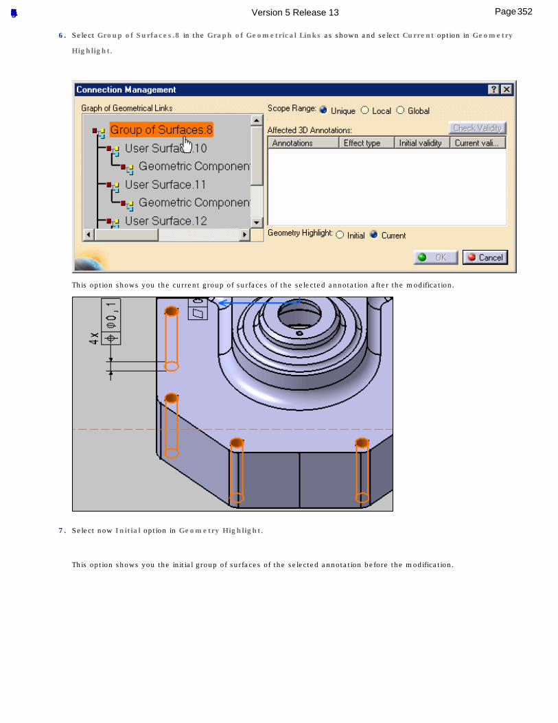
6. Select Group of Surfaces.8 in the Graph of Geometrical Links as shown and select Current option in Geometry
Highlight.
This option shows you the current group of surfaces of the selected annotation after the modification.
7. Select now Initial option in Geometry Highlight.
This option shows you the initial group of surfaces of the selected annotation before the modification.
352Page Functional Tolerancing & Annotation Version 5 Release 13
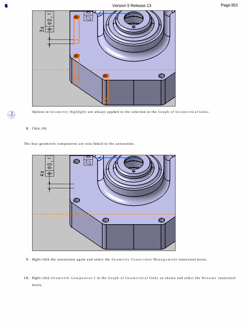
Options in Geometry Highlight are always applied to the selection in the Graph of Geometrical Links.
8. Click OK.
The four geometric components are now linked to the annotation.
9. Right-click the annotation again and select the Geometry Connection Management contextual menu.
10. Right-click Geometric Component.1 in the Graph of Geometrical Links as shown and select the Rename contextual
menu.
353Page Functional Tolerancing & Annotation Version 5 Release 13
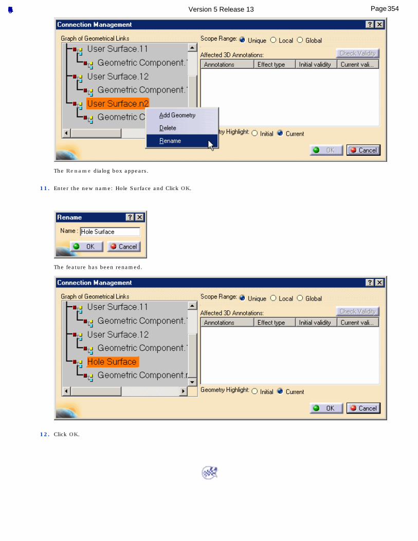
The Rename dialog box appears.
11. Enter the new name: Hole Surface and Click OK.
The feature has been renamed.
12. Click OK.
354Page Functional Tolerancing & Annotation Version 5 Release 13
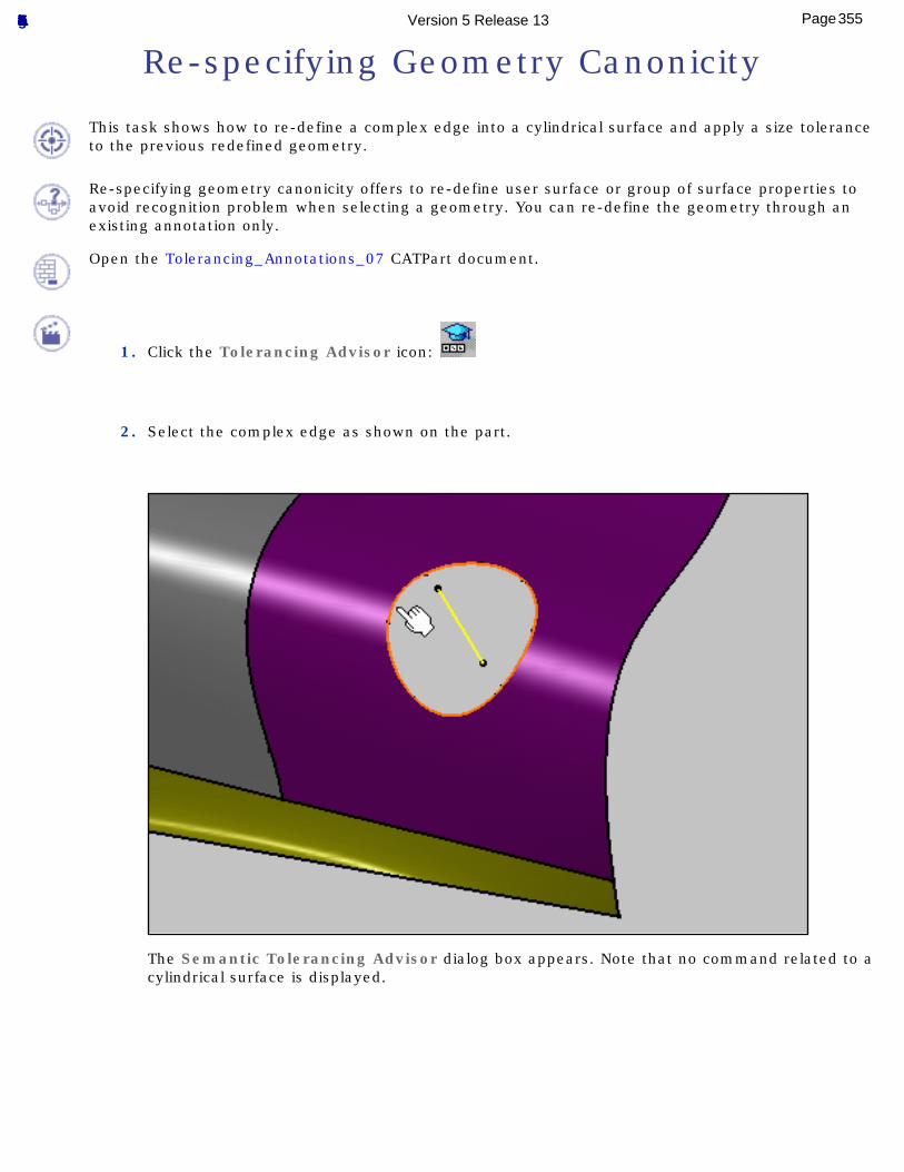
Re-specifying Geometry Canonicity
This task shows how to re-define a complex edge into a cylindrical surface and apply a size tolerance to the previous redefined geometry.
Re-specifying geometry canonicity offers to re-define user surface or group of surface properties to avoid recognition problem when selecting a geometry. You can re-define the geometry through an existing annotation only.
Open the Tolerancing_Annotations_07 CATPart document.
1. Click the Tolerancing Advisor icon:
2. Select the complex edge as shown on the part.
The Semantic Tolerancing Advisor dialog box appears. Note that no command related to a cylindrical surface is displayed.
355Page Functional Tolerancing & Annotation Version 5 Release 13
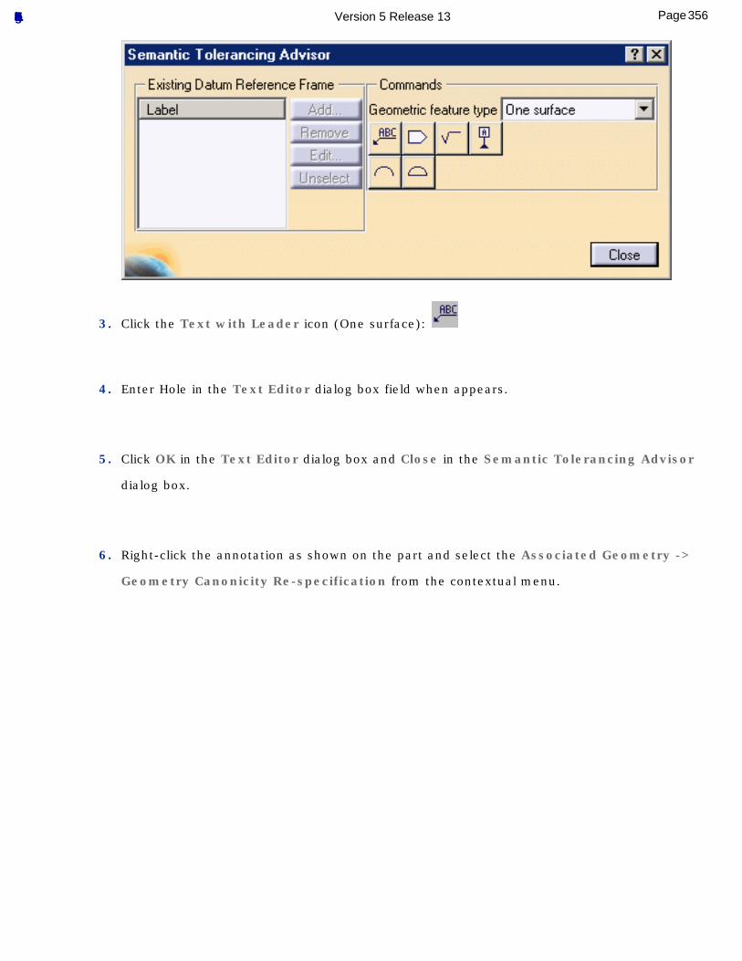
3. Click the Text with Leader icon (One surface):
4. Enter Hole in the Text Editor dialog box field when appears.
5. Click OK in the Text Editor dialog box and Close in the Semantic Tolerancing Advisor
dialog box.
6. Right-click the annotation as shown on the part and select the Associated Geometry ->
Geometry Canonicity Re-specification from the contextual menu.
356Page Functional Tolerancing & Annotation Version 5 Release 13
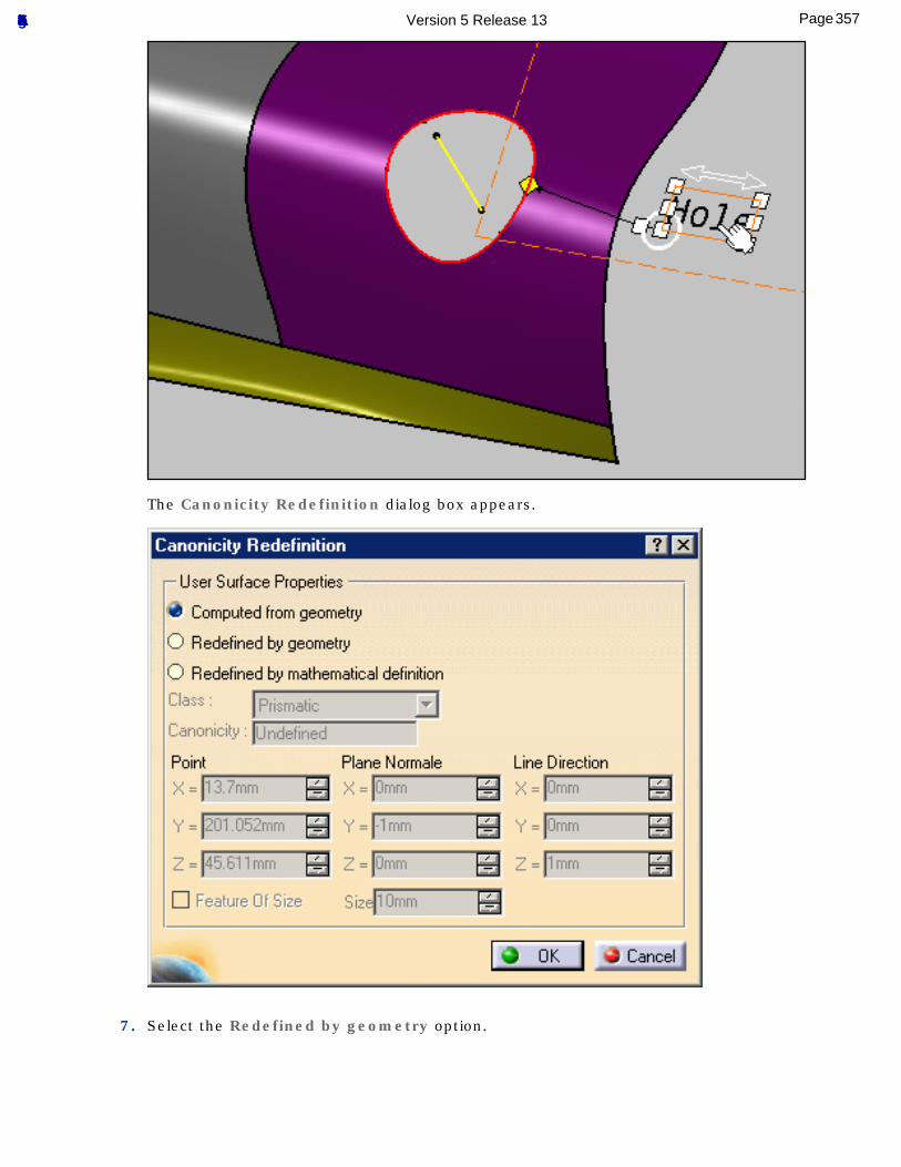
The Canonicity Redefinition dialog box appears.
7. Select the Redefined by geometry option.
357Page Functional Tolerancing & Annotation Version 5 Release 13
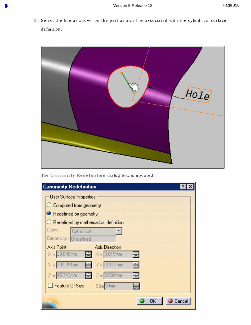
8. Select the line as shown on the part as axis line associated with the cylindrical surface
definition.
The Canonicity Redefinition dialog box is updated.
358Page Functional Tolerancing & Annotation Version 5 Release 13
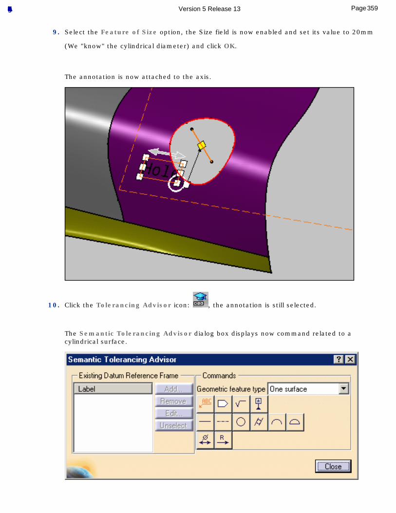
9. Select the Feature of Size option, the Size field is now enabled and set its value to 20mm
(We "know" the cylindrical diameter) and click OK.
The annotation is now attached to the axis.
10. Click the Tolerancing Advisor icon: , the annotation is still selected.
The Semantic Tolerancing Advisor dialog box displays now command related to a cylindrical surface.
359Page Functional Tolerancing & Annotation Version 5 Release 13
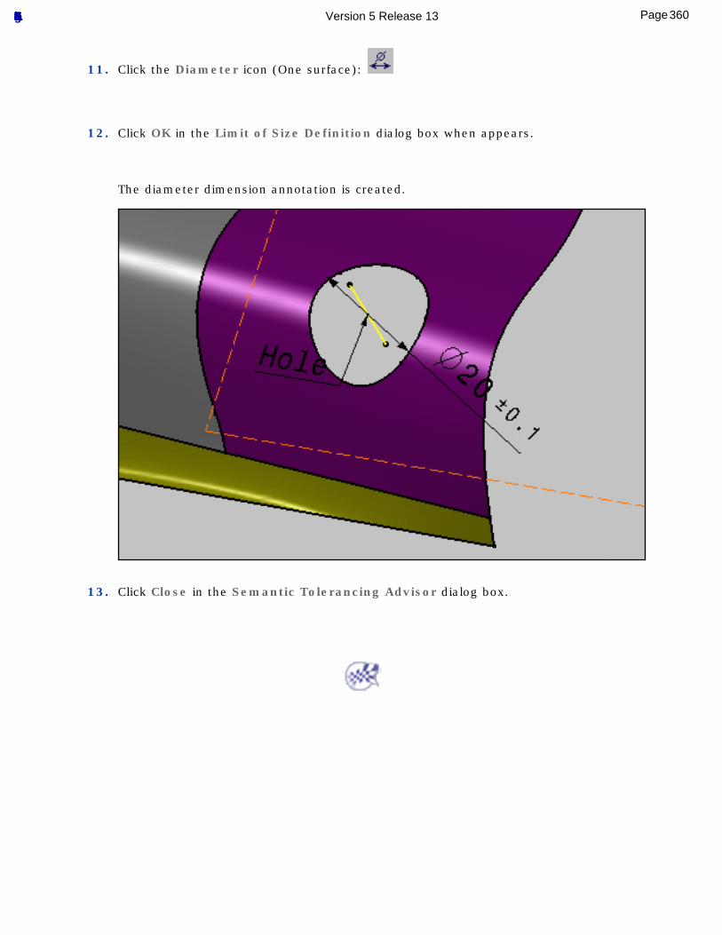
11. Click the Diameter icon (One surface):
12. Click OK in the Limit of Size Definition dialog box when appears.
The diameter dimension annotation is created.
13. Click Close in the Semantic Tolerancing Advisor dialog box.
360Page Functional Tolerancing & Annotation Version 5 Release 13
Reporting Annotations
Generate a Check Report: click this icon to generate the report.
Customize the Reporting: click this icon and select the desired options.
361Page Functional Tolerancing & Annotation Version 5 Release 13
Generating a Check Report
This tasks shows you how to generate a report checking whether tolerancing rules are respected or not. These rules depend on the standard you are using. See Tolerancing settings.
Open the Tolerancing_Annotations_02 CATPart document.
1. Make sure the options Html and Both are activated in the Tolerancing Rule Settings dialog box.
For more information, refer to Customizing the Reporting.
2. Click the Report icon
The application generates the report in the browser you usually use and displays it onscreen using the options as specified in the Custom Report command.
The file provides you with the path of the CATPart document you are using and the date of generation. In our example, all the rules are respected as mentioned by the green symbols and the 100% success message.
3. Click any rule name to obtain detailed information
4. To generate the other type of report, use the Customize Report command to set the options File and Both.
5. Click the Report icon
The application generates the report.
362Page Functional Tolerancing & Annotation Version 5 Release 13
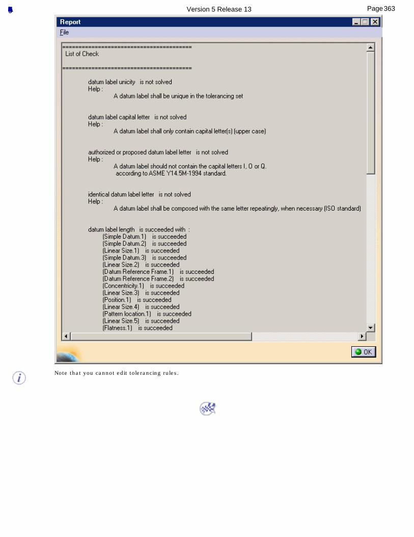
Note that you cannot edit tolerancing rules.
363Page Functional Tolerancing & Annotation Version 5 Release 13
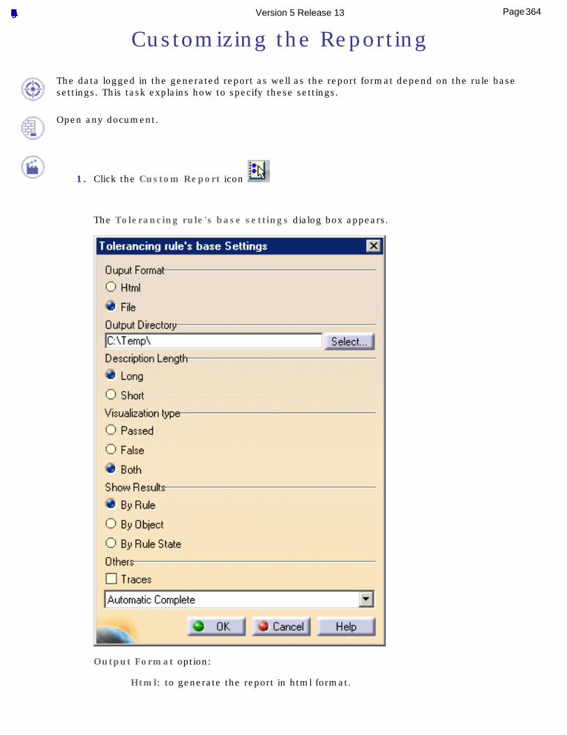
Customizing the Reporting
The data logged in the generated report as well as the report format depend on the rule base settings. This task explains how to specify these settings.
Open any document.
1. Click the Custom Report icon
The Tolerancing rule's base settings dialog box appears.
Output Format option:
Html: to generate the report in html format.
364Page Functional Tolerancing & Annotation Version 5 Release 13
File: to generate the report in text format.In this mode, the Description Length and the Show results options are activated by default.
Description Length option:
Long: to insert the Help message specified at the check creation.
Short: if you do not need the Help message.
Visualization type option:
Passed: to include in the report only information about the features for which the checks are valid.
False: to include in the report only information about the features for which the checks are invalid.
Both: to include in the report information about all the features on which a check has been applied.
Show Results option:
By Rule: to organize your report data by rule in the file.
By Object: to organize your report data by object.
By Rule: State to organize your report data by rule state.
Others option:
Traces: to display the steps of the solve process.
Automatic Complete: to perform an initialization and a solve operation on the objects whenever the part is updated.
Automatic Optimized: to perform a new solve on the last changes.
Manual Solve: to perform a manual solve.
2. Click OK to apply the settings to the rule base.
Unless you want to modify the check report characteristics, you don't have to re-specify the settings each time you generate a report.
365Page Functional Tolerancing & Annotation Version 5 Release 13
Annotation AssociativityDifferent types of associativity characterize the 3D Functional Tolerancing and Annotation workbench, such as associativity between the 3D part and the navigation tree for example.
Annotation associativity lets you highlight the geometrical element, Part Design feature or Generative Shape Design feature that is related to an annotation. You can turn an annotation into the default annotation.
Query 3D Annotations: activate or deactivate this icon.
Create an Automatic Default Annotation: click this icon, select the annotation.
366Page Functional Tolerancing & Annotation Version 5 Release 13
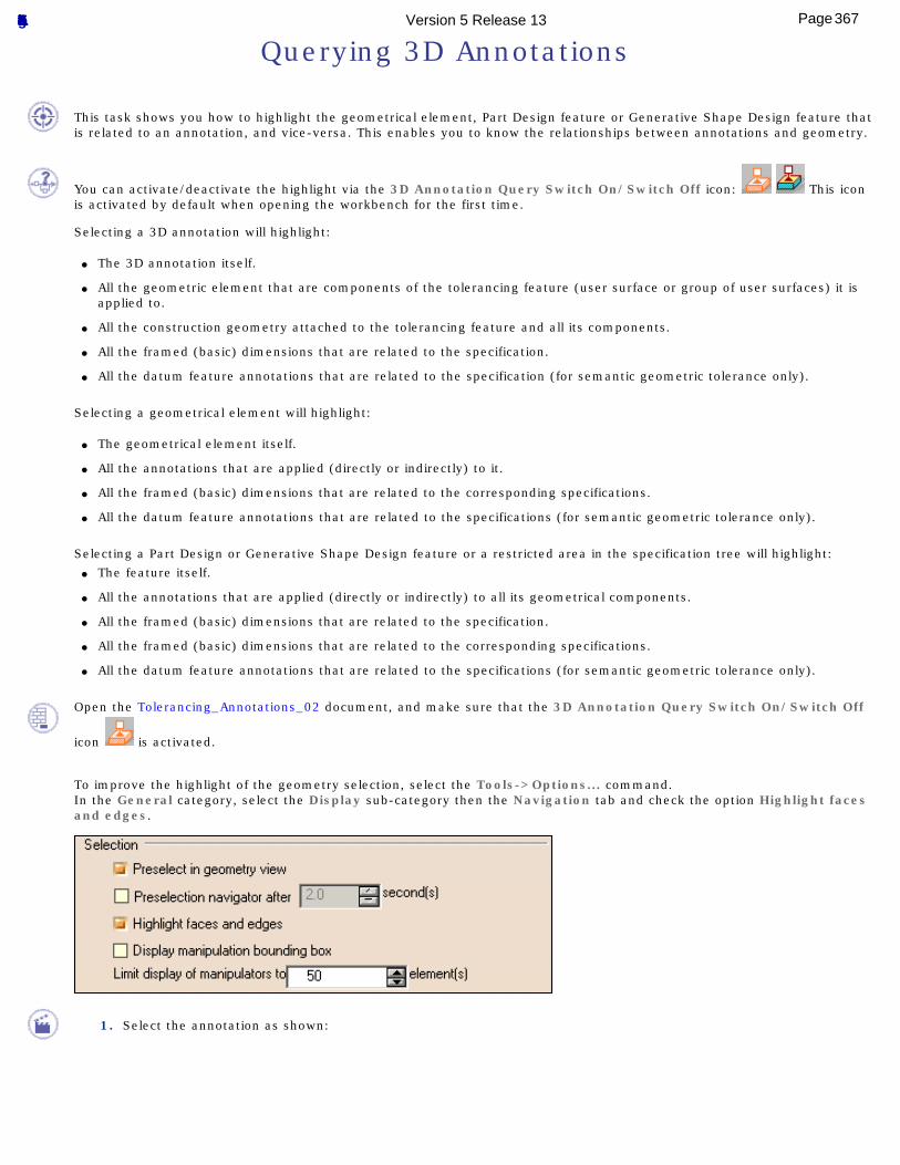
Querying 3D Annotations
This task shows you how to highlight the geometrical element, Part Design feature or Generative Shape Design feature that is related to an annotation, and vice-versa. This enables you to know the relationships between annotations and geometry.
You can activate/deactivate the highlight via the 3D Annotation Query Switch On/Switch Off icon: This icon is activated by default when opening the workbench for the first time.
Selecting a 3D annotation will highlight:
● The 3D annotation itself.
● All the geometric element that are components of the tolerancing feature (user surface or group of user surfaces) it is applied to.
● All the construction geometry attached to the tolerancing feature and all its components.
● All the framed (basic) dimensions that are related to the specification.
● All the datum feature annotations that are related to the specification (for semantic geometric tolerance only).
Selecting a geometrical element will highlight:
● The geometrical element itself.
● All the annotations that are applied (directly or indirectly) to it.
● All the framed (basic) dimensions that are related to the corresponding specifications.
● All the datum feature annotations that are related to the specifications (for semantic geometric tolerance only).
Selecting a Part Design or Generative Shape Design feature or a restricted area in the specification tree will highlight:● The feature itself.
● All the annotations that are applied (directly or indirectly) to all its geometrical components.
● All the framed (basic) dimensions that are related to the specification.
● All the framed (basic) dimensions that are related to the corresponding specifications.
● All the datum feature annotations that are related to the specifications (for semantic geometric tolerance only).
Open the Tolerancing_Annotations_02 document, and make sure that the 3D Annotation Query Switch On/Switch Off
icon is activated.
To improve the highlight of the geometry selection, select the Tools->Options... command.In the General category, select the Display sub-category then the Navigation tab and check the option Highlight faces and edges.
1. Select the annotation as shown:
367Page Functional Tolerancing & Annotation Version 5 Release 13
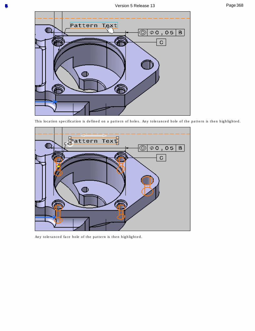
This location specification is defined on a pattern of holes. Any toleranced hole of the pattern is then highlighted.
Any toleranced face hole of the pattern is then highlighted.
368Page Functional Tolerancing & Annotation Version 5 Release 13
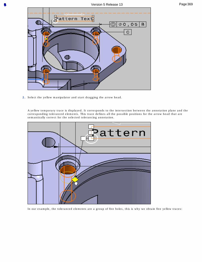
2. Select the yellow manipulator and start dragging the arrow head.
A yellow temporary trace is displayed. It corresponds to the intersection between the annotation plane and the corresponding toleranced elements. This trace defines all the possible positions for the arrow head that are semantically correct for the selected tolerancing annotation.
In our example, the toleranced elements are a group of five holes, this is why we obtain five yellow traces:
369Page Functional Tolerancing & Annotation Version 5 Release 13
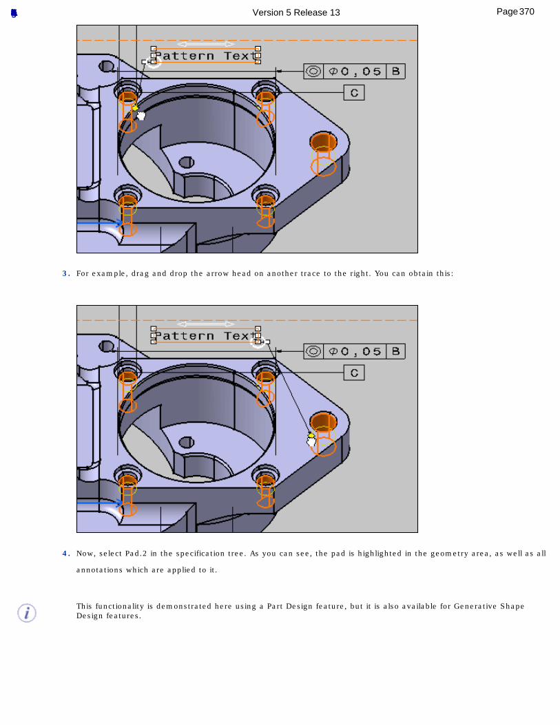
3. For example, drag and drop the arrow head on another trace to the right. You can obtain this:
4. Now, select Pad.2 in the specification tree. As you can see, the pad is highlighted in the geometry area, as well as all
annotations which are applied to it.
This functionality is demonstrated here using a Part Design feature, but it is also available for Generative Shape Design features.
370Page Functional Tolerancing & Annotation Version 5 Release 13
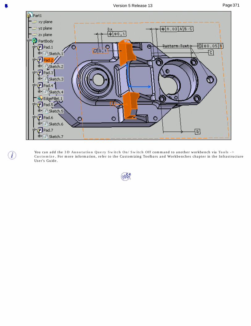
You can add the 3D Annotation Query Switch On/Switch Off command to another workbench via Tools -> Customize. For more information, refer to the Customizing Toolbars and Workbenches chapter in the Infrastructure User's Guide.
371Page Functional Tolerancing & Annotation Version 5 Release 13
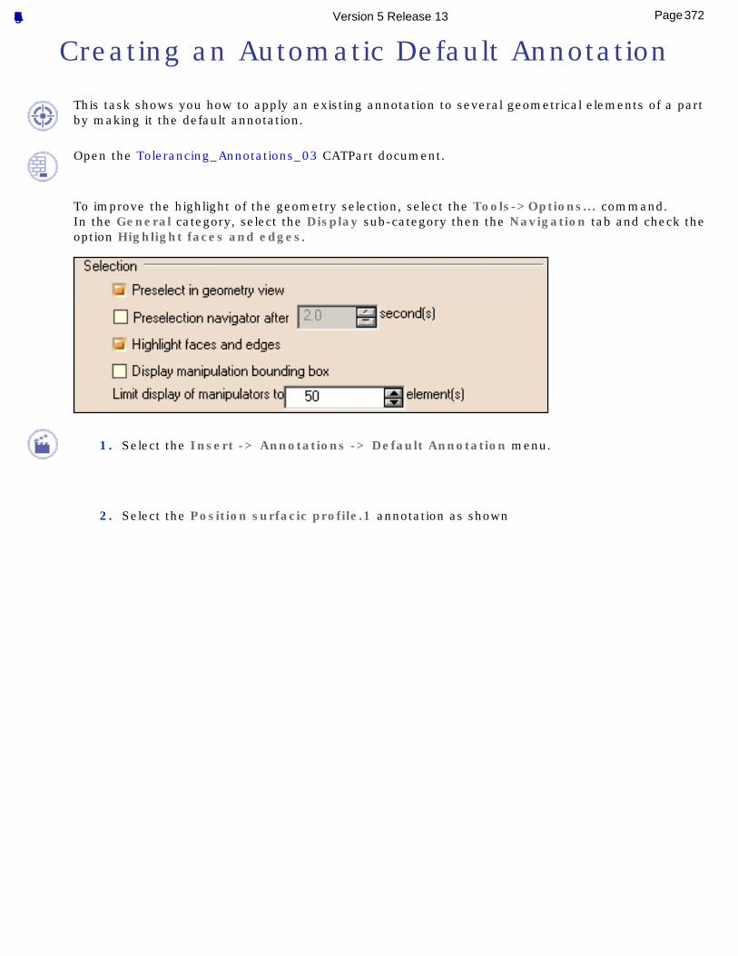
Creating an Automatic Default Annotation
This task shows you how to apply an existing annotation to several geometrical elements of a part by making it the default annotation.
Open the Tolerancing_Annotations_03 CATPart document.
To improve the highlight of the geometry selection, select the Tools->Options... command.In the General category, select the Display sub-category then the Navigation tab and check the option Highlight faces and edges.
1. Select the Insert -> Annotations -> Default Annotation menu.
2. Select the Position surfacic profile.1 annotation as shown
372Page Functional Tolerancing & Annotation Version 5 Release 13
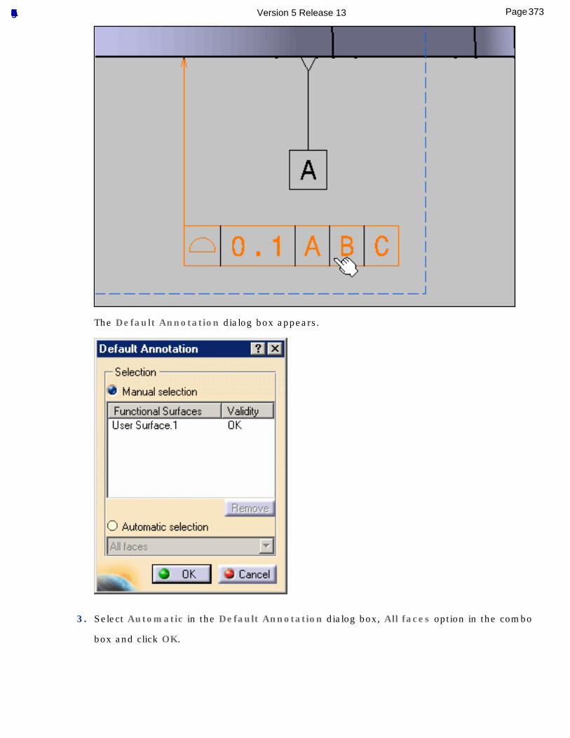
The Default Annotation dialog box appears.
3. Select Automatic in the Default Annotation dialog box, All faces option in the combo
box and click OK.
373Page Functional Tolerancing & Annotation Version 5 Release 13
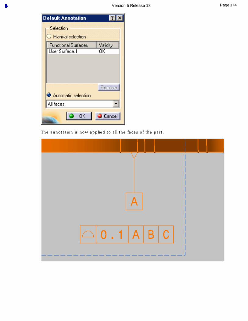
The annotation is now applied to all the faces of the part.
374Page Functional Tolerancing & Annotation Version 5 Release 13
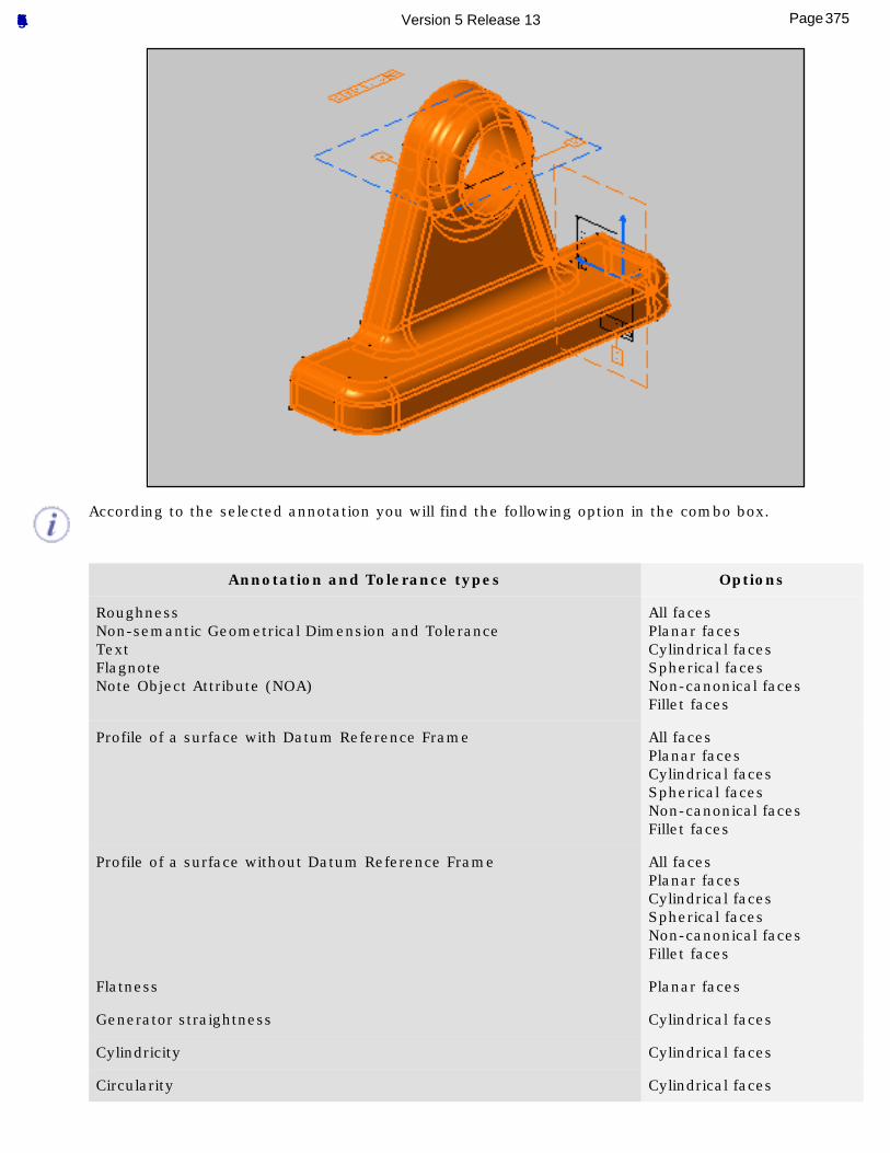
According to the selected annotation you will find the following option in the combo box.
Annotation and Tolerance types Options
RoughnessNon-semantic Geometrical Dimension and ToleranceTextFlagnoteNote Object Attribute (NOA)
All facesPlanar facesCylindrical facesSpherical facesNon-canonical facesFillet faces
Profile of a surface with Datum Reference Frame All facesPlanar facesCylindrical facesSpherical facesNon-canonical facesFillet faces
Profile of a surface without Datum Reference Frame All facesPlanar facesCylindrical facesSpherical facesNon-canonical facesFillet faces
Flatness Planar faces
Generator straightness Cylindrical faces
Cylindricity Cylindrical faces
Circularity Cylindrical faces
375Page Functional Tolerancing & Annotation Version 5 Release 13
Radius size Cylindrical facesSpherical facesFillet faces
Diameter size Cylindrical facesSpherical faces
376Page Functional Tolerancing & Annotation Version 5 Release 13
Managing Power Copies
Create Power Copy: select the Insert ->Advanced Replication Tools -> Powercopy Creation command,select the elements making up the Power Copy from the specification tree,define a name for the Power Copy and its reference elements then choose an icon for identifying it.
Instantiate Power Copy: select the Insert -> Instantiate From Document... command,select the document or catalog containing the Power Copy ,complete the Inputs within the dialog box selecting adequate elements in the geometric area.
Save Power Copy into a Catalog: select the Power Copy from the specification tree,select the Insert -> Advanced Replication Tools -> Save In Catalog... command,enter the catalog name and click Open.
377Page Functional Tolerancing & Annotation Version 5 Release 13
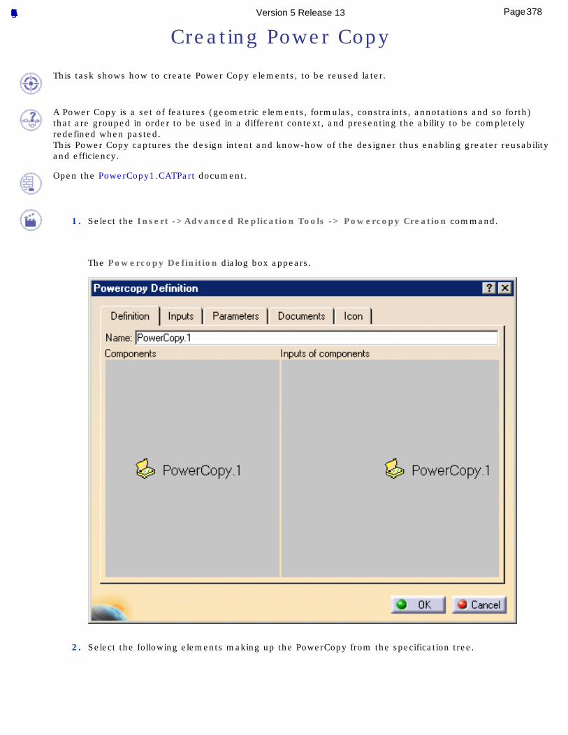
Creating Power Copy
This task shows how to create Power Copy elements, to be reused later.
A Power Copy is a set of features (geometric elements, formulas, constraints, annotations and so forth) that are grouped in order to be used in a different context, and presenting the ability to be completely redefined when pasted.This Power Copy captures the design intent and know-how of the designer thus enabling greater reusability and efficiency.
Open the PowerCopy1.CATPart document.
1. Select the Insert ->Advanced Replication Tools -> Powercopy Creation command.
The Powercopy Definition dialog box appears.
2. Select the following elements making up the PowerCopy from the specification tree.
378Page Functional Tolerancing & Annotation Version 5 Release 13
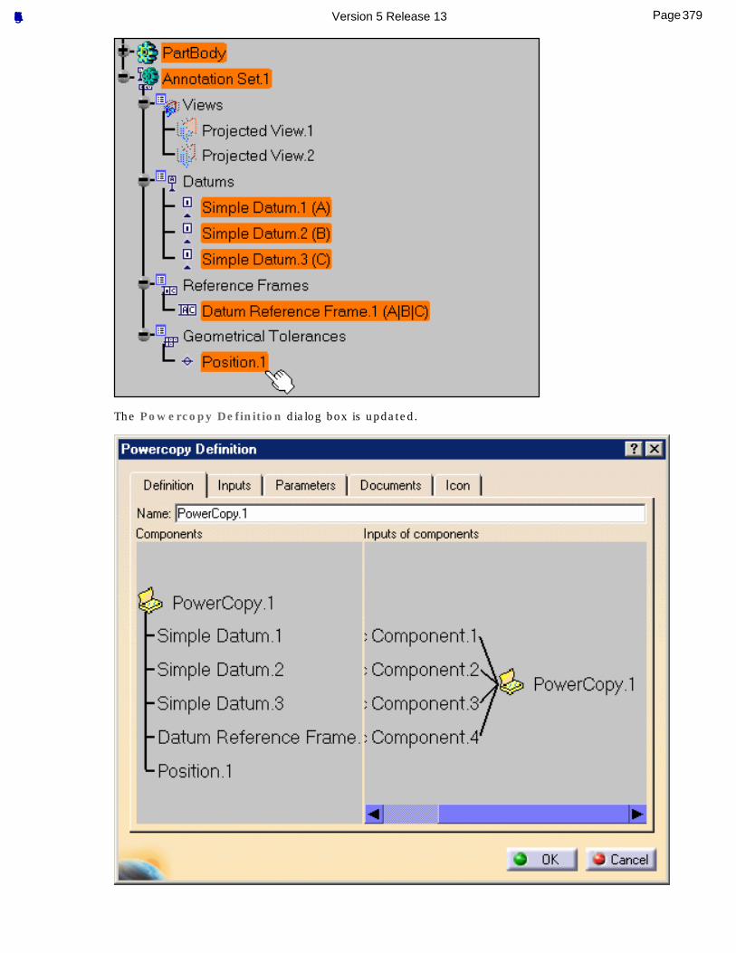
The Powercopy Definition dialog box is updated.
379Page Functional Tolerancing & Annotation Version 5 Release 13
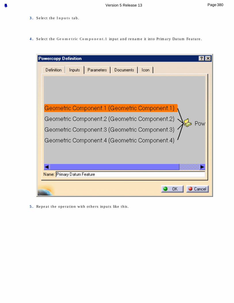
3. Select the Inputs tab.
4. Select the Geometric Component.1 input and rename it into Primary Datum Feature.
5. Repeat the operation with others inputs like this.
380Page Functional Tolerancing & Annotation Version 5 Release 13
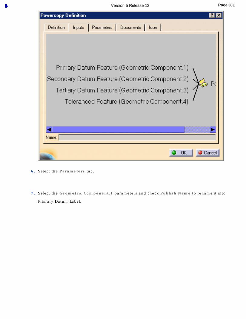
6. Select the Parameters tab.
7. Select the Geometric Component.1 parameters and check Publish Name to rename it into
Primary Datum Label.
381Page Functional Tolerancing & Annotation Version 5 Release 13
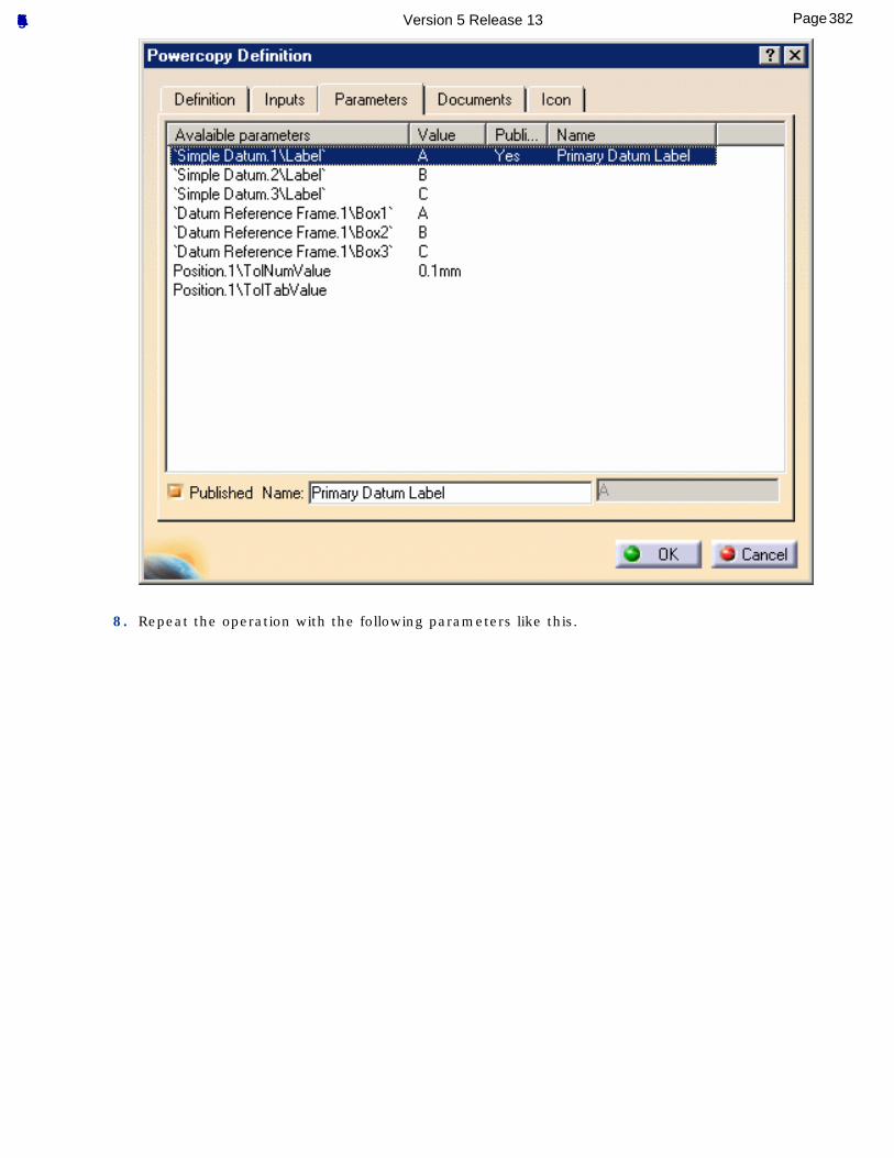
8. Repeat the operation with the following parameters like this.
382Page Functional Tolerancing & Annotation Version 5 Release 13
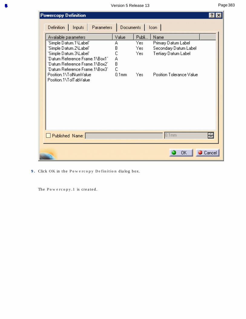
9. Click OK in the Powercopy Definition dialog box.
The Powercopy.1 is created.
383Page Functional Tolerancing & Annotation Version 5 Release 13
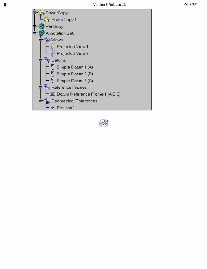
384Page Functional Tolerancing & Annotation Version 5 Release 13
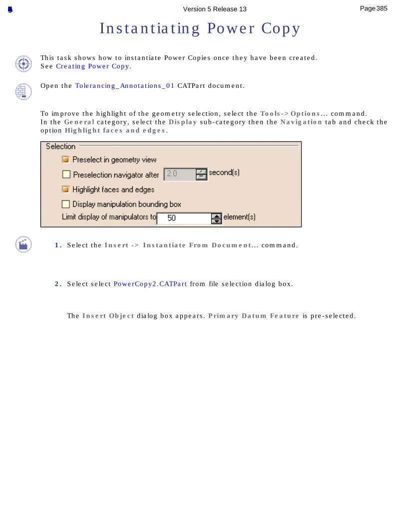
Instantiating Power Copy
This task shows how to instantiate Power Copies once they have been created.See Creating Power Copy.
Open the Tolerancing_Annotations_01 CATPart document.
To improve the highlight of the geometry selection, select the Tools->Options... command.In the General category, select the Display sub-category then the Navigation tab and check the option Highlight faces and edges.
1. Select the Insert -> Instantiate From Document... command.
2. Select select PowerCopy2.CATPart from file selection dialog box.
The Insert Object dialog box appears. Primary Datum Feature is pre-selected.
385Page Functional Tolerancing & Annotation Version 5 Release 13
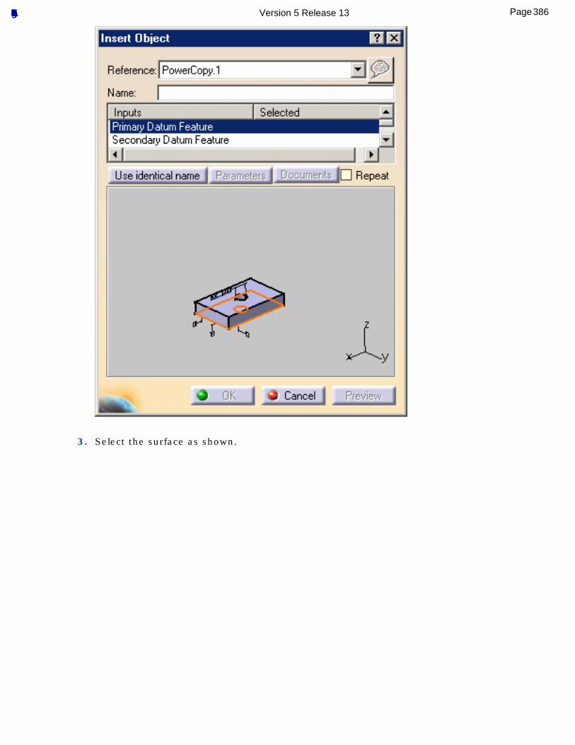
3. Select the surface as shown.
386Page Functional Tolerancing & Annotation Version 5 Release 13
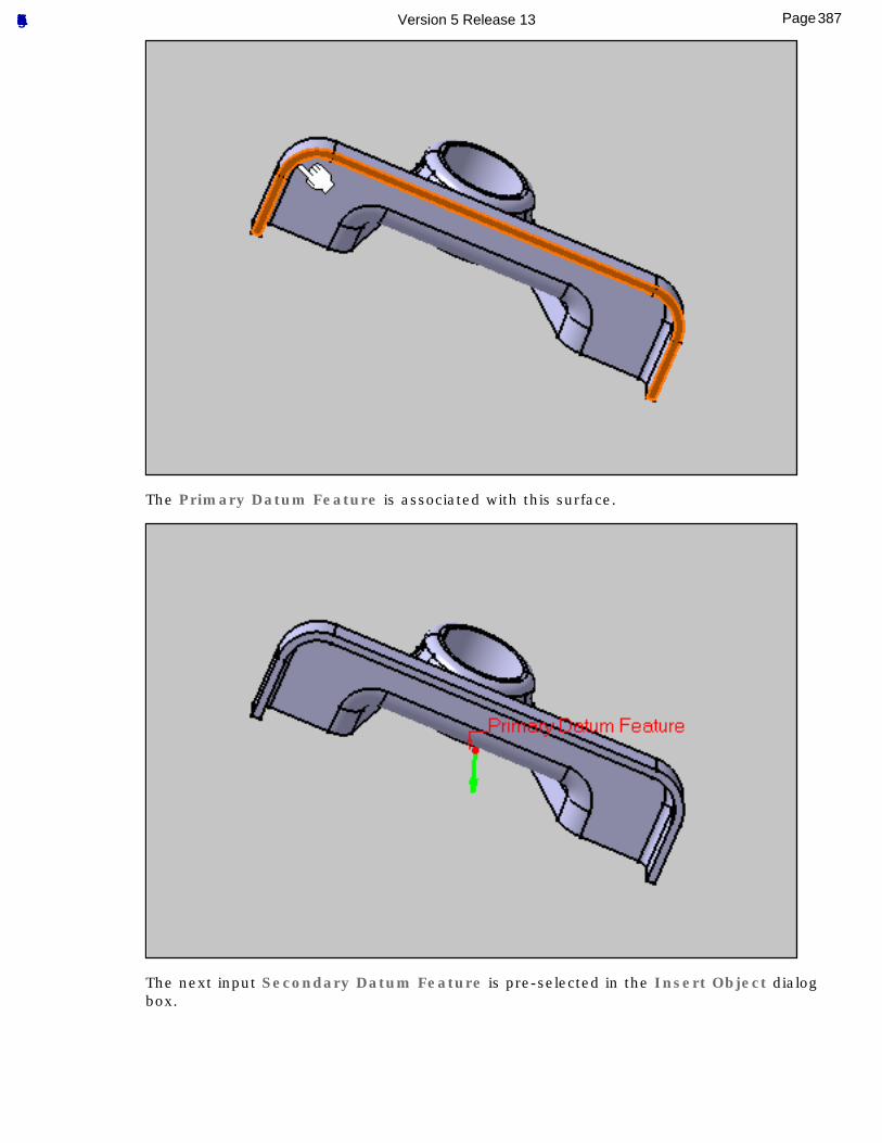
The Primary Datum Feature is associated with this surface.
The next input Secondary Datum Feature is pre-selected in the Insert Object dialog box.
387Page Functional Tolerancing & Annotation Version 5 Release 13
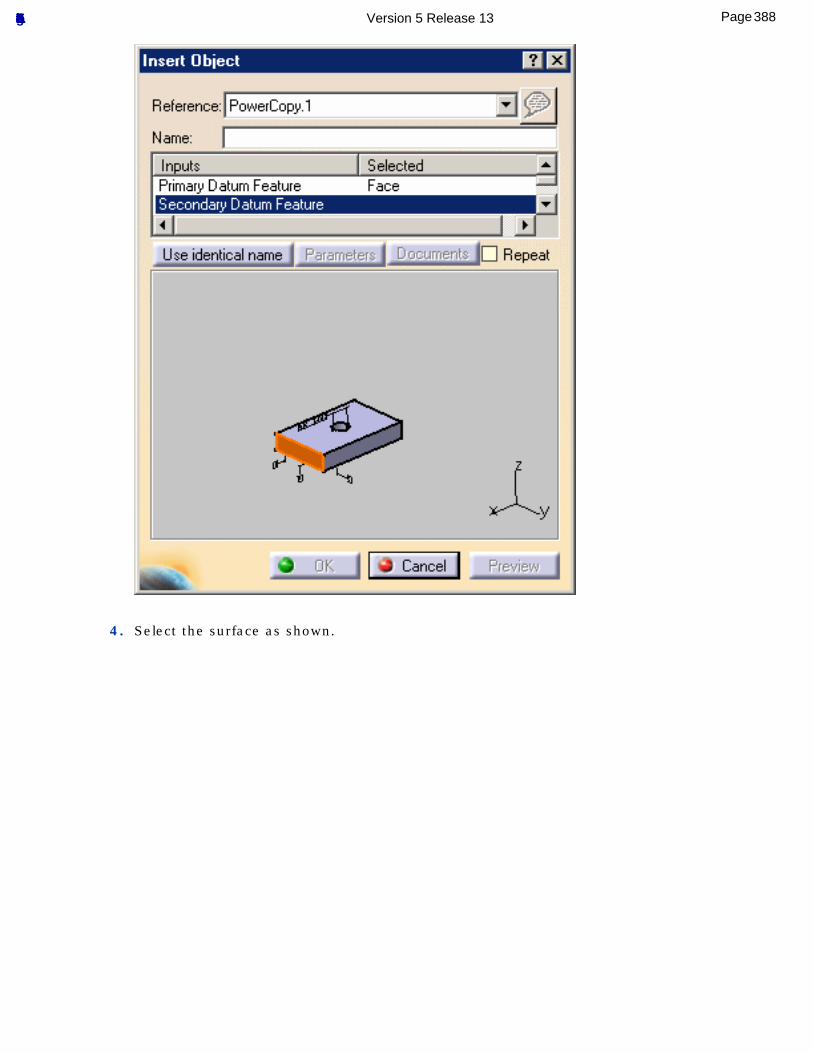
4. Select the surface as shown.
388Page Functional Tolerancing & Annotation Version 5 Release 13
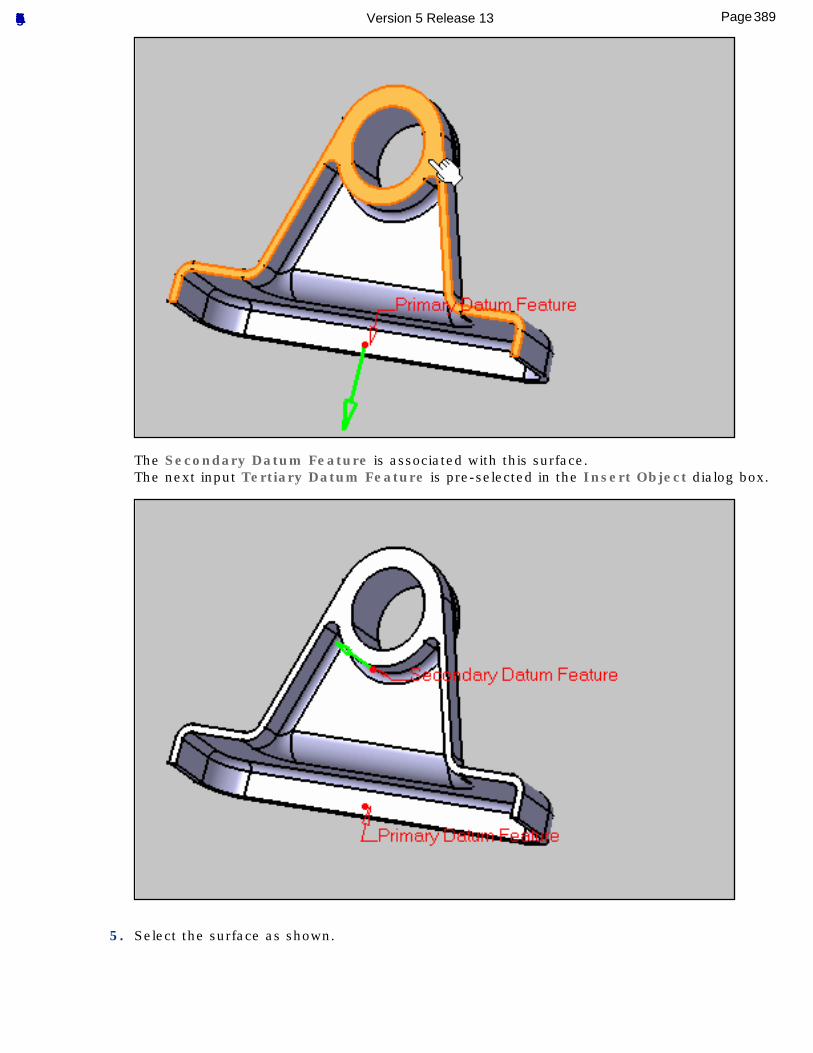
The Secondary Datum Feature is associated with this surface.The next input Tertiary Datum Feature is pre-selected in the Insert Object dialog box.
5. Select the surface as shown.
389Page Functional Tolerancing & Annotation Version 5 Release 13
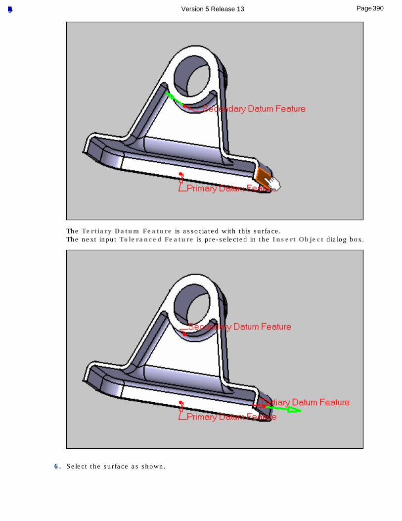
The Tertiary Datum Feature is associated with this surface.The next input Toleranced Feature is pre-selected in the Insert Object dialog box.
6. Select the surface as shown.
390Page Functional Tolerancing & Annotation Version 5 Release 13
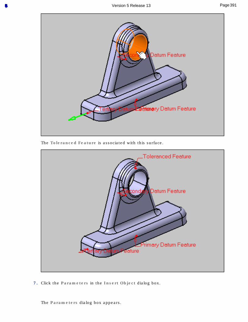
The Toleranced Feature is associated with this surface.
7. Click the Parameters in the Insert Object dialog box.
The Parameters dialog box appears.
391Page Functional Tolerancing & Annotation Version 5 Release 13
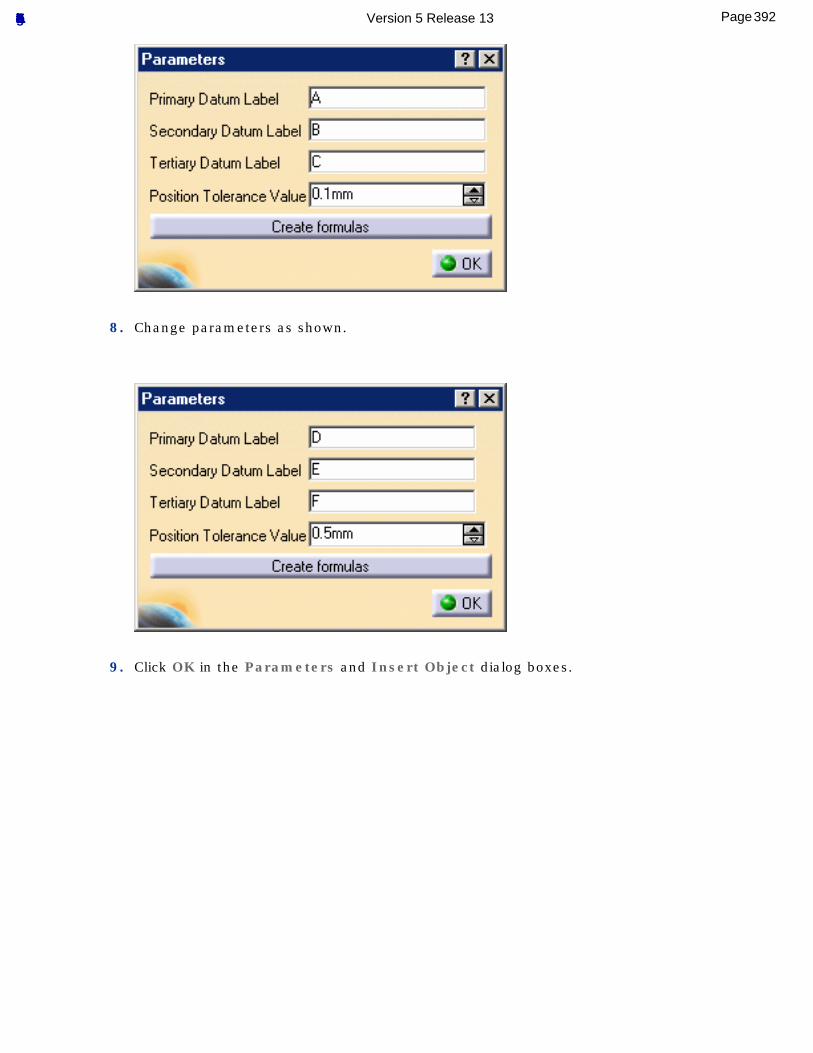
8. Change parameters as shown.
9. Click OK in the Parameters and Insert Object dialog boxes.
392Page Functional Tolerancing & Annotation Version 5 Release 13
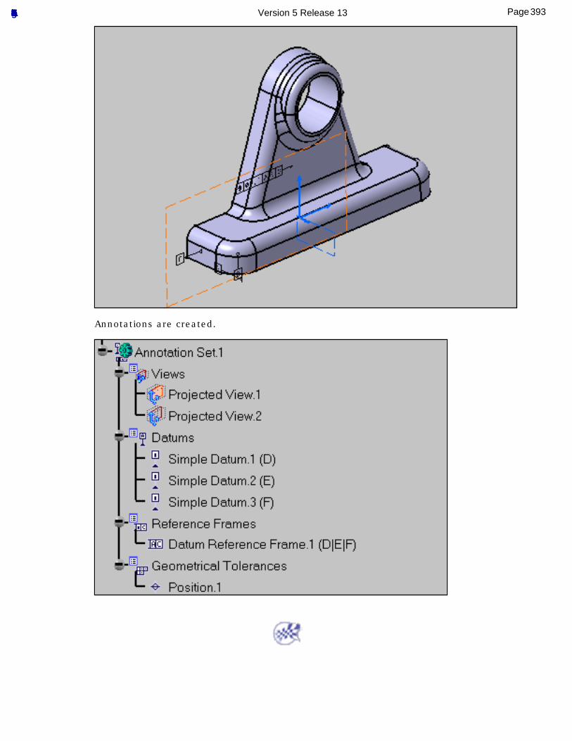
Annotations are created.
393Page Functional Tolerancing & Annotation Version 5 Release 13
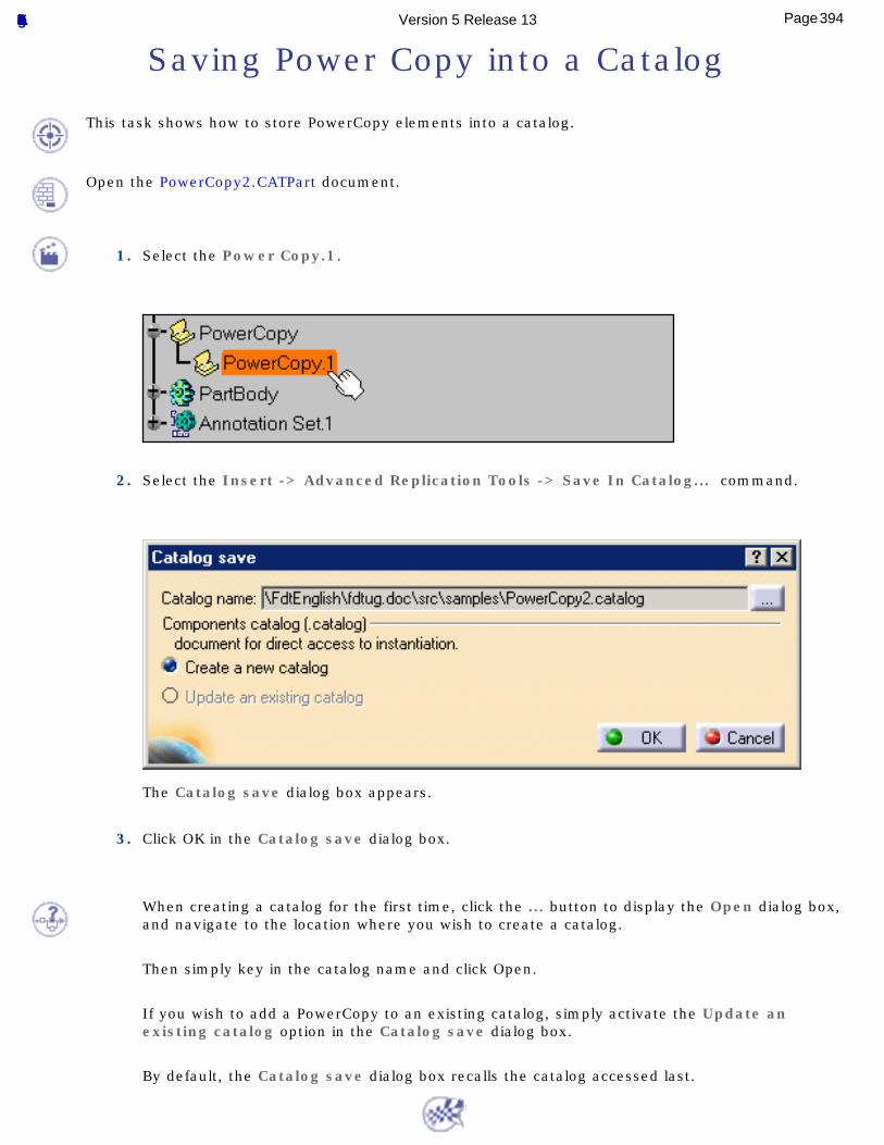
Saving Power Copy into a Catalog
This task shows how to store PowerCopy elements into a catalog.
Open the PowerCopy2.CATPart document.
1. Select the Power Copy.1.
2. Select the Insert -> Advanced Replication Tools -> Save In Catalog... command.
The Catalog save dialog box appears.
3. Click OK in the Catalog save dialog box.
When creating a catalog for the first time, click the ... button to display the Open dialog box, and navigate to the location where you wish to create a catalog.
Then simply key in the catalog name and click Open.
If you wish to add a PowerCopy to an existing catalog, simply activate the Update an existing catalog option in the Catalog save dialog box.
By default, the Catalog save dialog box recalls the catalog accessed last.
394Page Functional Tolerancing & Annotation Version 5 Release 13
Providing Constructed Geometry for 3D Annotations
These functionalities provide the capability to query and manage the constructed geometry that is associated to a tolerancing feature (User surface and Group of surfaces features).
Constructed geometry (such as center point, axis, median plane, gage plane, etc) is very often used in order to define the theoretical dimensions of parts or products (framed dimensioning).These constructed elements do represent the tolerancing feature (User surface and Group of surfaces features) and are used to define the tolerance zone position of geometrical tolerances, the related position of the datums of a datum reference frame, the size and position of a partial surface or a datum target.The capability that is described here allows either managing constructed geometry that has been manually created by the user.
The existing geometry is the represented geometry, the constructed geometry is the representing geometry.
Create an Automatic Constructed Geometry: click this icon, select the context.
Manage Constructed Geometry: click this icon, select the represented geometry then the representing geometry.
395Page Functional Tolerancing & Annotation Version 5 Release 13
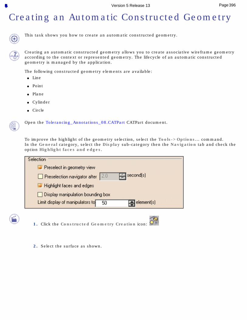
Creating an Automatic Constructed Geometry
This task shows you how to create an automatic constructed geometry.
Creating an automatic constructed geometry allows you to create associative wireframe geometry according to the context or represented geometry. The lifecycle of an automatic constructed geometry is managed by the application.
The following constructed geometry elements are available: ● Line
● Point
● Plane
● Cylinder
● Circle
Open the Tolerancing_Annotations_08.CATPart CATPart document.
To improve the highlight of the geometry selection, select the Tools->Options... command.In the General category, select the Display sub-category then the Navigation tab and check the option Highlight faces and edges.
1. Click the Constructed Geometry Creation icon:
2. Select the surface as shown.
396Page Functional Tolerancing & Annotation Version 5 Release 13
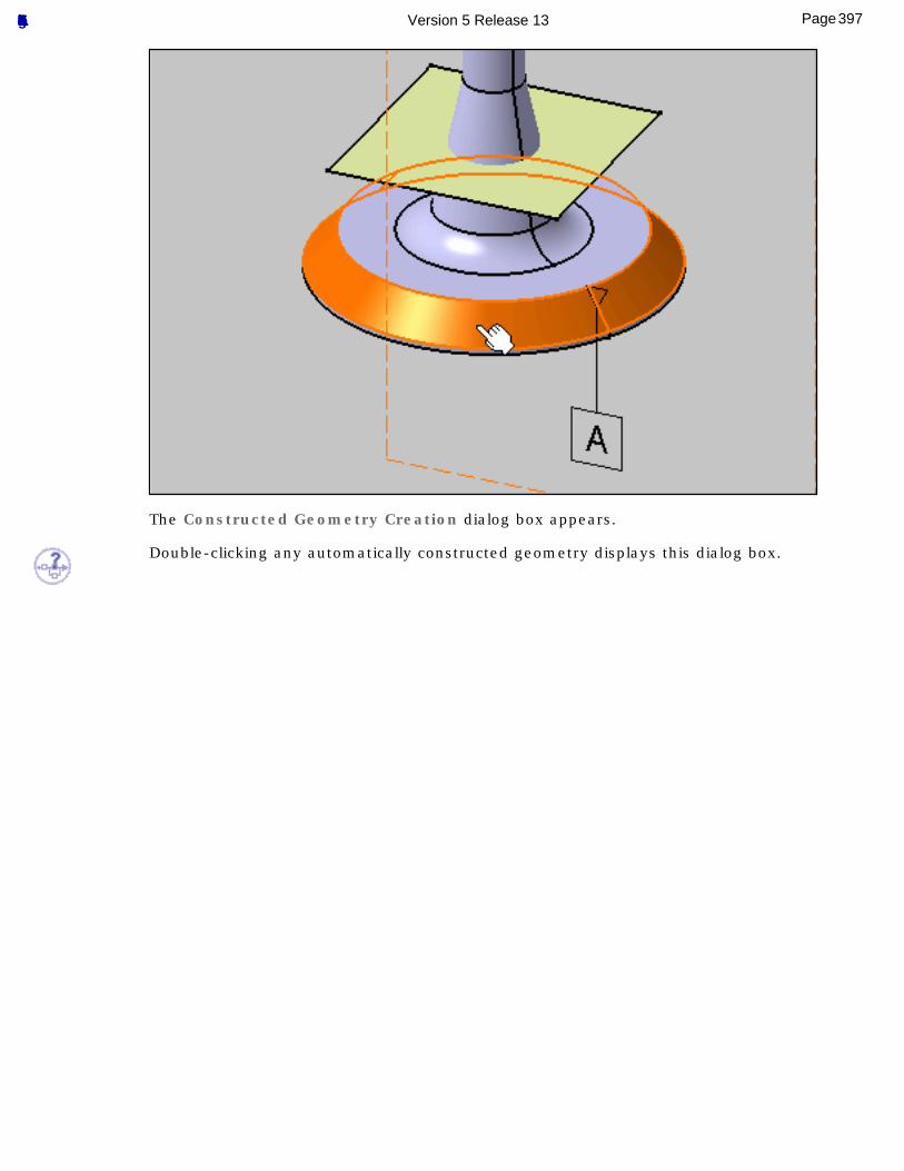
The Constructed Geometry Creation dialog box appears.
Double-clicking any automatically constructed geometry displays this dialog box.
397Page Functional Tolerancing & Annotation Version 5 Release 13
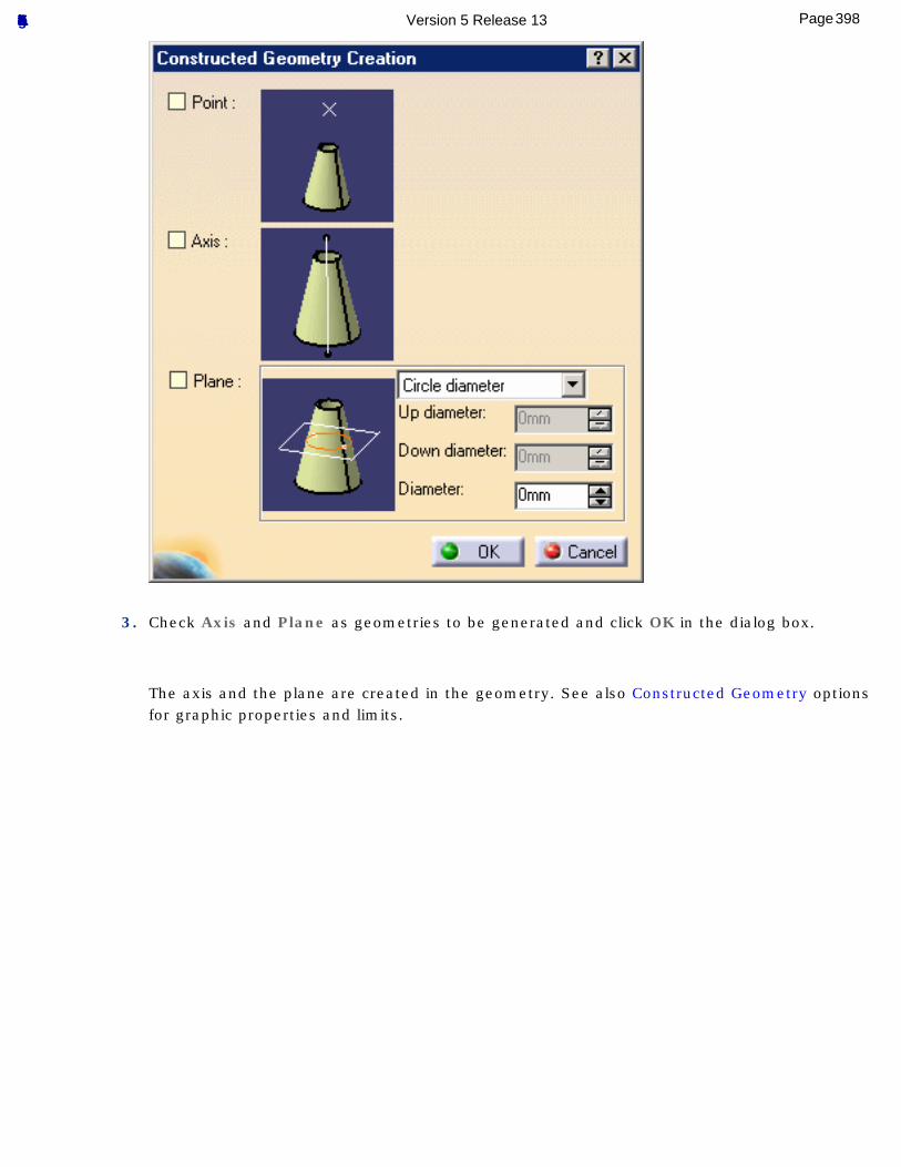
3. Check Axis and Plane as geometries to be generated and click OK in the dialog box.
The axis and the plane are created in the geometry. See also Constructed Geometry options for graphic properties and limits.
398Page Functional Tolerancing & Annotation Version 5 Release 13
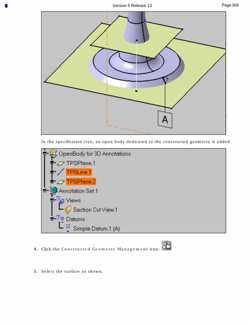
In the specification tree, an open body dedicated to the constructed geometry is added.
4. Click the Constructed Geometry Management icon:
5. Select the surface as shown.
399Page Functional Tolerancing & Annotation Version 5 Release 13
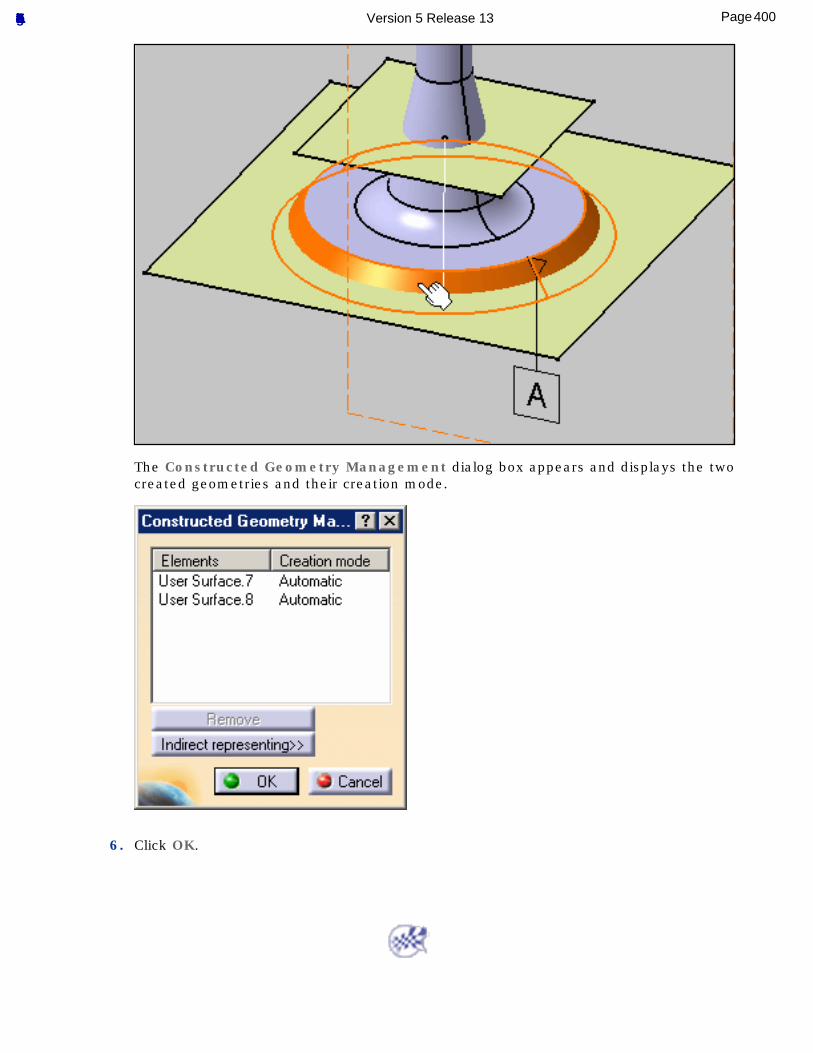
The Constructed Geometry Management dialog box appears and displays the two created geometries and their creation mode.
6. Click OK.
400Page Functional Tolerancing & Annotation Version 5 Release 13
Managing Constructed Geometry
This task shows you how to manage constructed geometry.This functionality allows you to:
● Create a manual constructed geometry. See also Creating an Automatic Constructed Geometry.
● Associate/disassociate an existing geometry as constructed geometry (or representing geometry) of a tolerancing feature (User surface and Group of surfaces) with another existing geometry as represented geometry.
● You can associate an existing constructed geometry (or representing geometry) with another existing geometry. In this case, the constructed geometry previous association is removed, then associated with the new selection.
● An existing geometry cannot be its constructed geometry (or representing geometry) and represented geometry at the same time.
● Query the direct or inherited constructed geometry of a given tolerancing feature.
● Remove existing constructed geometry, but not its indirect representing geometries.
● One or several representing geometries may be referenced by a represented geometry, but a representing geometry element can be referenced by only one represented geometry.
Creating a manual constructed geometry allows you to associate an existing geometry as constructed geometry of a tolerancing feature (User surface and Group of surfaces). The lifecycle of manually constructed geometry is not managed by the application.
For this, you can select:● A 3D annotation: the corresponding tolerancing feature is retrieved.
● A geometrical element: the corresponding tolerancing feature is retrieved or created.
Open the Tolerancing_Annotations_08.CATPart CATPart document.
1. Click the Constructed Geometry Management icon:
2. Select the datum.
401Page Functional Tolerancing & Annotation Version 5 Release 13
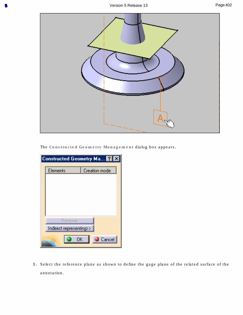
The Constructed Geometry Management dialog box appears.
3. Select the reference plane as shown to define the gage plane of the related surface of the
annotation.
402Page Functional Tolerancing & Annotation Version 5 Release 13
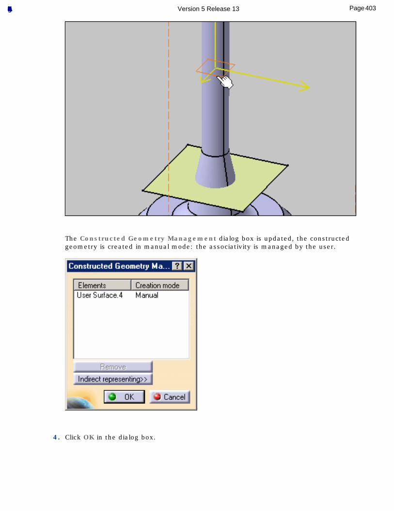
The Constructed Geometry Management dialog box is updated, the constructed geometry is created in manual mode: the associativity is managed by the user.
4. Click OK in the dialog box.
403Page Functional Tolerancing & Annotation Version 5 Release 13
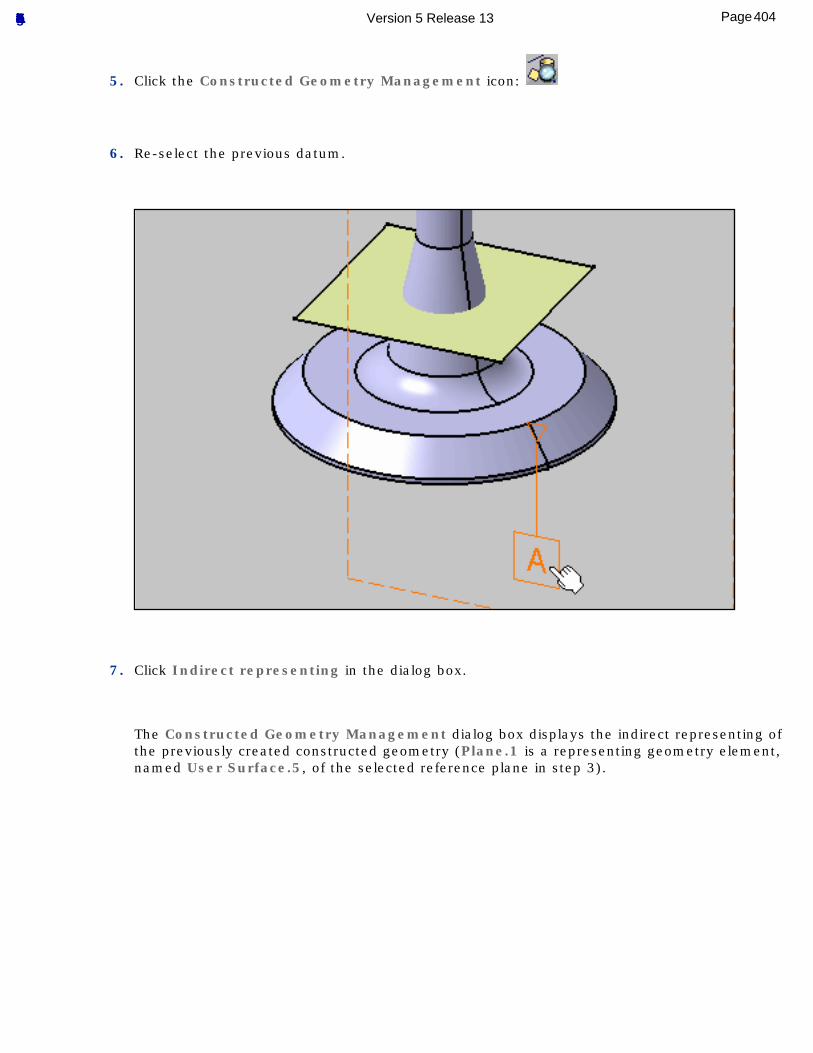
5. Click the Constructed Geometry Management icon:
6. Re-select the previous datum.
7. Click Indirect representing in the dialog box.
The Constructed Geometry Management dialog box displays the indirect representing of the previously created constructed geometry (Plane.1 is a representing geometry element, named User Surface.5, of the selected reference plane in step 3).
404Page Functional Tolerancing & Annotation Version 5 Release 13
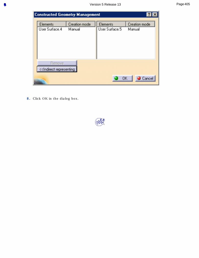
8. Click OK in the dialog box.
405Page Functional Tolerancing & Annotation Version 5 Release 13
InteroperabilityThis section contains interoperability information about the Functional Tolerancing & Annotation workbench.
Optimal CATIA PLM Usability for Functional Tolerancing & Annotation
406Page Functional Tolerancing & Annotation Version 5 Release 13
Optimal CATIA PLM Usability for Functional Tolerancing & Annotation
When working with ENOVIA V5, the safe save mode ensures that you only create data in CATIA V5 that can be correctly saved in ENOVIA V5.
ENOVIA V5 offers two different storage modes: Workpackage (Document kept - Publications Exposed) and Explode (Document not kept). Functional Tolerancing & Annotation has been configured to work in the Workpackage mode only.
Functional Tolerancing & Annotation Commands in Enovia V5
All the Functional Tolerancing & Annotation commands are available with the Workpackage mode in Enovia V5.
407Page Functional Tolerancing & Annotation Version 5 Release 13
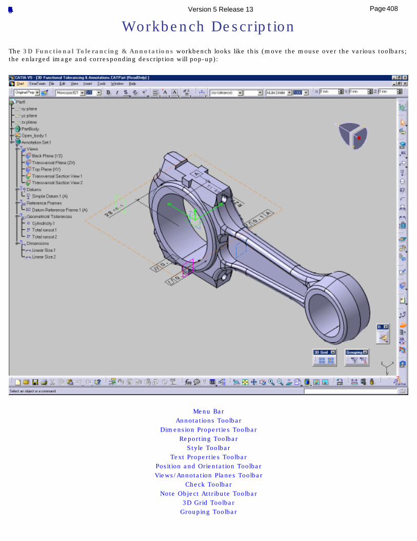
Workbench DescriptionThe 3D Functional Tolerancing & Annotations workbench looks like this (move the mouse over the various toolbars; the enlarged image and corresponding description will pop-up):
[Menu Bar][Annotations Toolbar]
[Dimension Properties Toolbar][Reporting Toolbar]
[Style Toolbar][Text Properties Toolbar]
[Position and Orientation Toolbar][Views/Annotation Planes Toolbar]
[Check Toolbar][Note Object Attribute Toolbar]
[3D Grid Toolbar][Grouping Toolbar]
408Page Functional Tolerancing & Annotation Version 5 Release 13
[Capture Toolbar][Geometry for 3D Annotations Toolbar]
[Deviations Toolbar (Compact)][Workshop Description]
409Page Functional Tolerancing & Annotation Version 5 Release 13
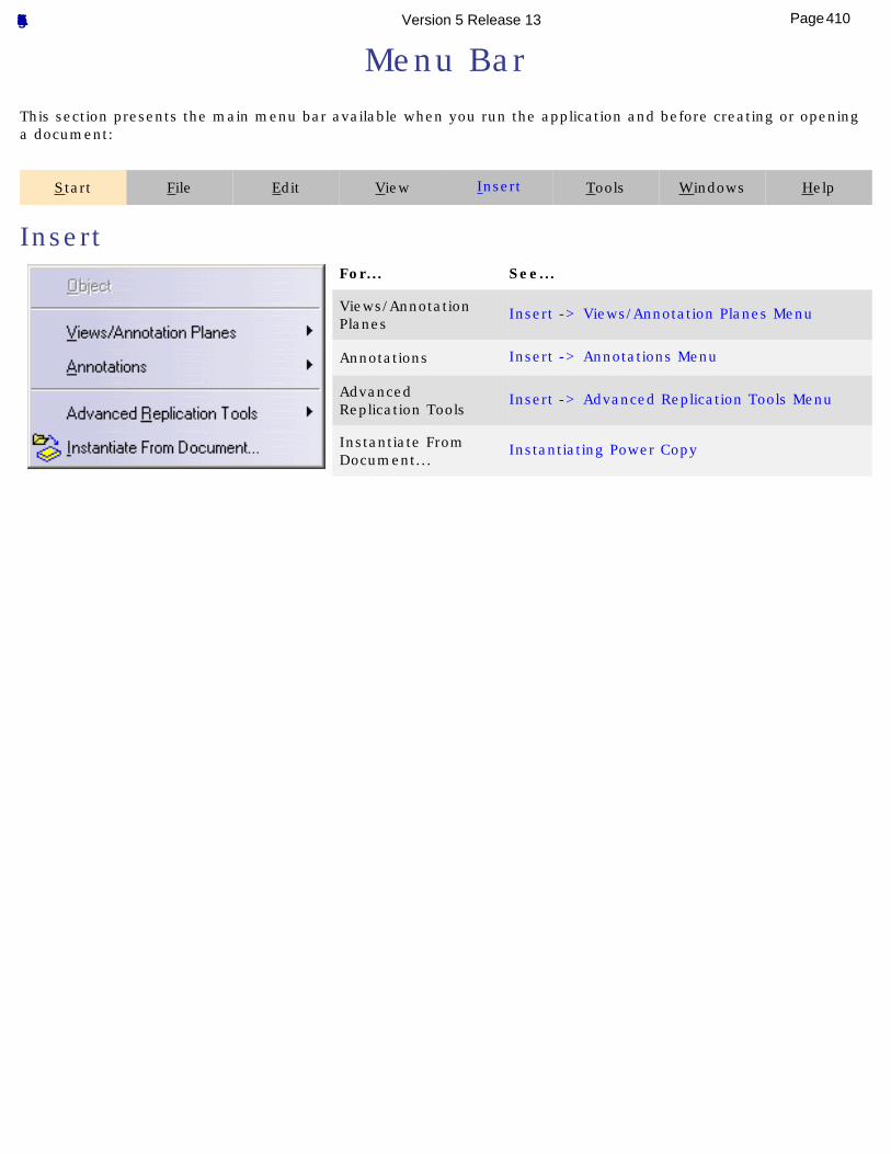
Menu BarThis section presents the main menu bar available when you run the application and before creating or opening a document:
Start File Edit View Insert Tools Windows Help
InsertFor... See...
Views/Annotation Planes
Insert -> Views/Annotation Planes Menu
Annotations Insert -> Annotations Menu
Advanced Replication Tools
Insert -> Advanced Replication Tools Menu
Instantiate From Document...
Instantiating Power Copy
410Page Functional Tolerancing & Annotation Version 5 Release 13
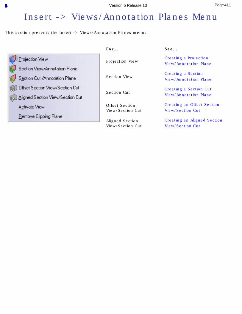
Insert -> Views/Annotation Planes MenuThis section presents the Insert -> Views/Annotation Planes menu:
For... See...
Projection View Creating a Projection View/Annotation Plane
Section View Creating a Section View/Annotation Plane
Section Cut Creating a Section Cut View/Annotation Plane
Offset Section View/Section Cut
Creating an Offset Section View/Section Cut
Aligned Section View/Section Cut
Creating an Aligned Section View/Section Cut
411Page Functional Tolerancing & Annotation Version 5 Release 13
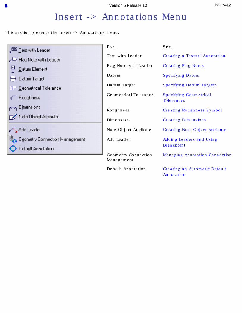
Insert -> Annotations MenuThis section presents the Insert -> Annotations menu:
For... See...
Text with Leader Creating a Textual Annotation
Flag Note with Leader Creating Flag Notes
Datum Specifying Datum
Datum Target Specifying Datum Targets
Geometrical Tolerance Specifying Geometrical Tolerances
Roughness Creating Roughness Symbol
Dimensions Creating Dimensions
Note Object Attribute Creating Note Object Attribute
Add Leader Adding Leaders and Using Breakpoint
Geometry Connection Management
Managing Annotation Connection
Default Annotation Creating an Automatic Default Annotation
412Page Functional Tolerancing & Annotation Version 5 Release 13
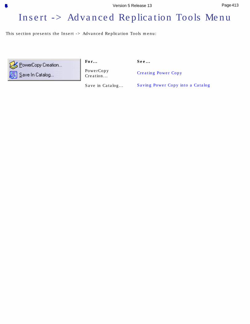
Insert -> Advanced Replication Tools MenuThis section presents the Insert -> Advanced Replication Tools menu:
For... See...
PowerCopy Creation...
Creating Power Copy
Save in Catalog... Saving Power Copy into a Catalog
413Page Functional Tolerancing & Annotation Version 5 Release 13
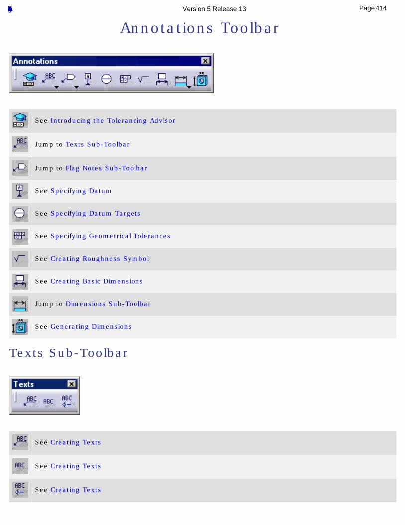
Annotations Toolbar
See Introducing the Tolerancing Advisor
Jump to Texts Sub-Toolbar
Jump to Flag Notes Sub-Toolbar
See Specifying Datum
See Specifying Datum Targets
See Specifying Geometrical Tolerances
See Creating Roughness Symbol
See Creating Basic Dimensions
Jump to Dimensions Sub-Toolbar
See Generating Dimensions
Texts Sub-Toolbar
See Creating Texts
See Creating Texts
See Creating Texts
414Page Functional Tolerancing & Annotation Version 5 Release 13
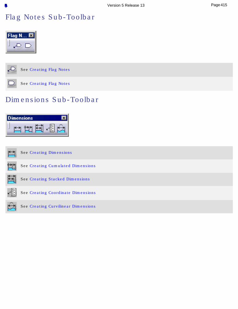
Flag Notes Sub-Toolbar
See Creating Flag Notes
See Creating Flag Notes
Dimensions Sub-Toolbar
See Creating Dimensions
See Creating Cumulated Dimensions
See Creating Stacked Dimensions
See Creating Coordinate Dimensions
See Creating Curvilinear Dimensions
415Page Functional Tolerancing & Annotation Version 5 Release 13
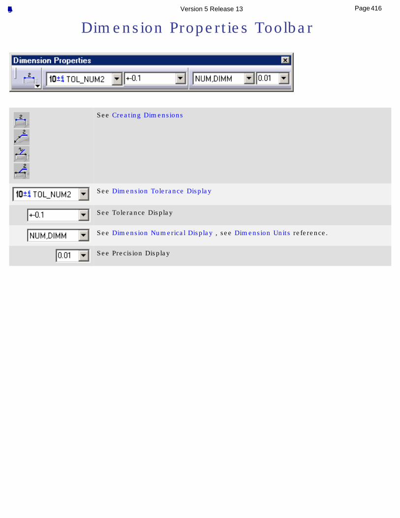
Dimension Properties Toolbar
See Creating Dimensions
See Dimension Tolerance Display
See Tolerance Display
See Dimension Numerical Display , see Dimension Units reference.
See Precision Display
416Page Functional Tolerancing & Annotation Version 5 Release 13
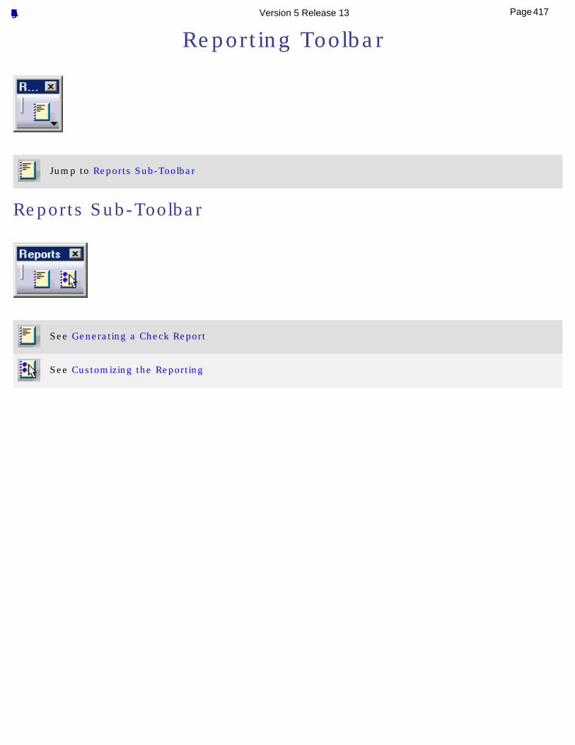
Reporting Toolbar
Jump to Reports Sub-Toolbar
Reports Sub-Toolbar
See Generating a Check Report
See Customizing the Reporting
417Page Functional Tolerancing & Annotation Version 5 Release 13
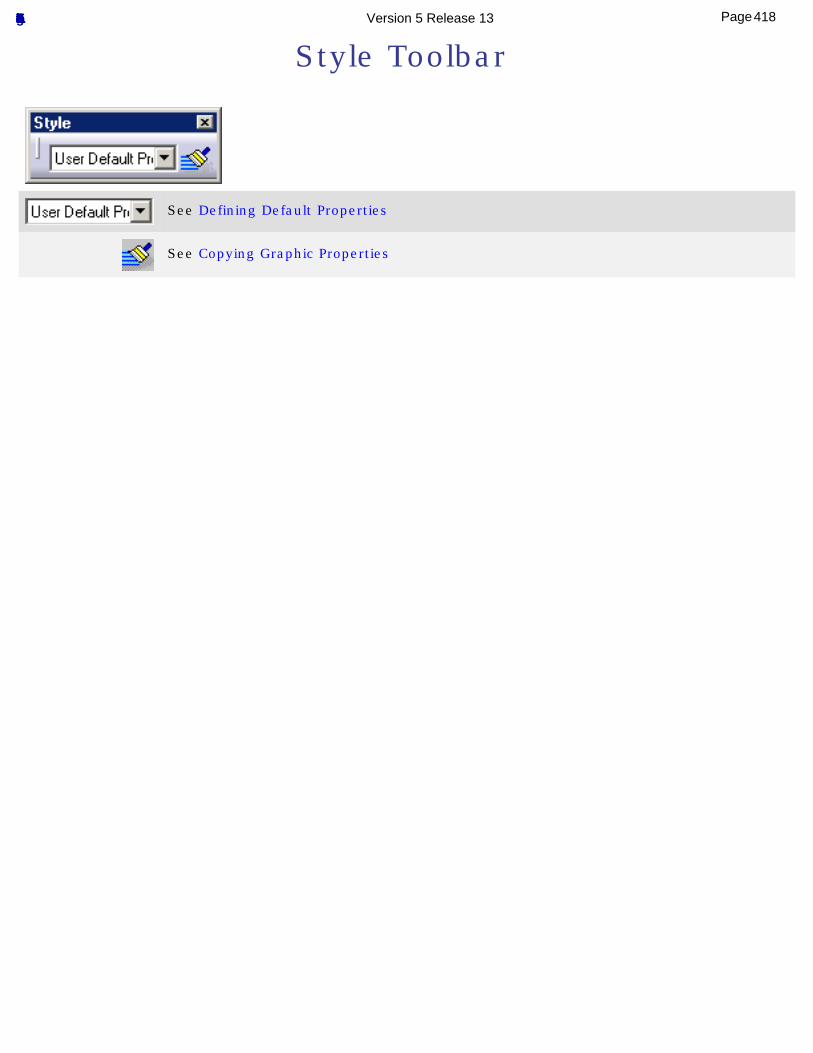
Style Toolbar
See Defining Default Properties
See Copying Graphic Properties
418Page Functional Tolerancing & Annotation Version 5 Release 13
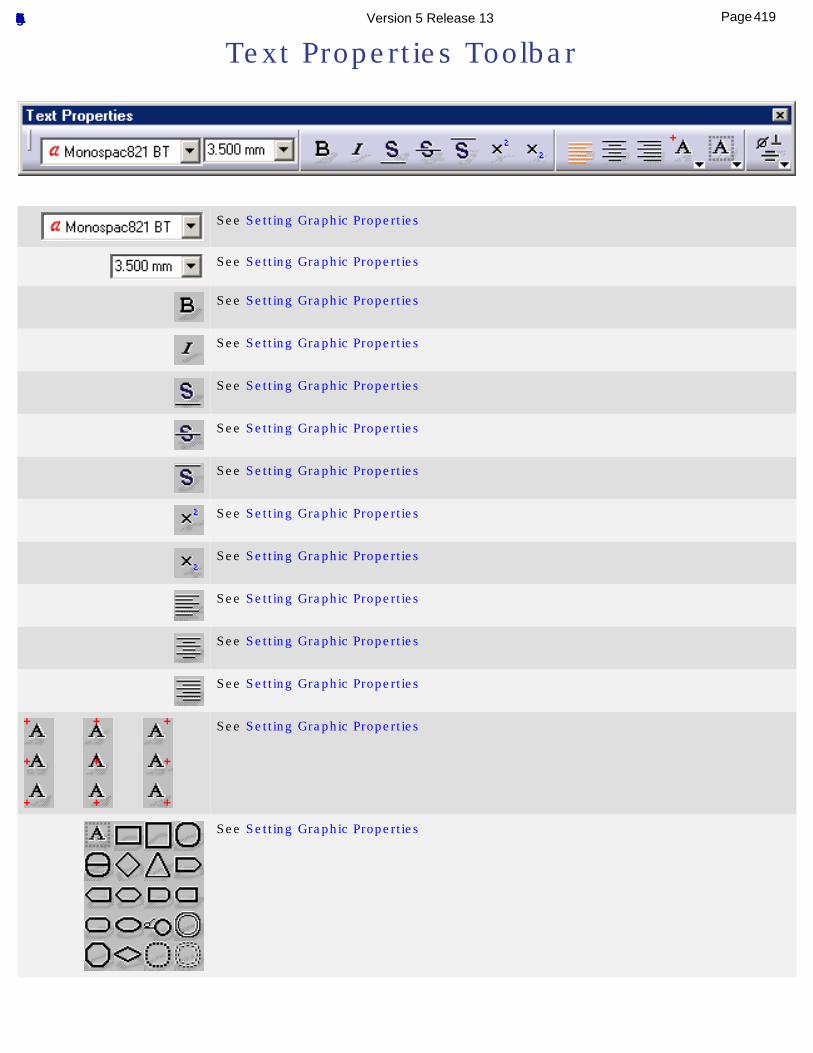
Text Properties Toolbar
See Setting Graphic Properties
See Setting Graphic Properties
See Setting Graphic Properties
See Setting Graphic Properties
See Setting Graphic Properties
See Setting Graphic Properties
See Setting Graphic Properties
See Setting Graphic Properties
See Setting Graphic Properties
See Setting Graphic Properties
See Setting Graphic Properties
See Setting Graphic Properties
See Setting Graphic Properties
See Setting Graphic Properties
419Page Functional Tolerancing & Annotation Version 5 Release 13
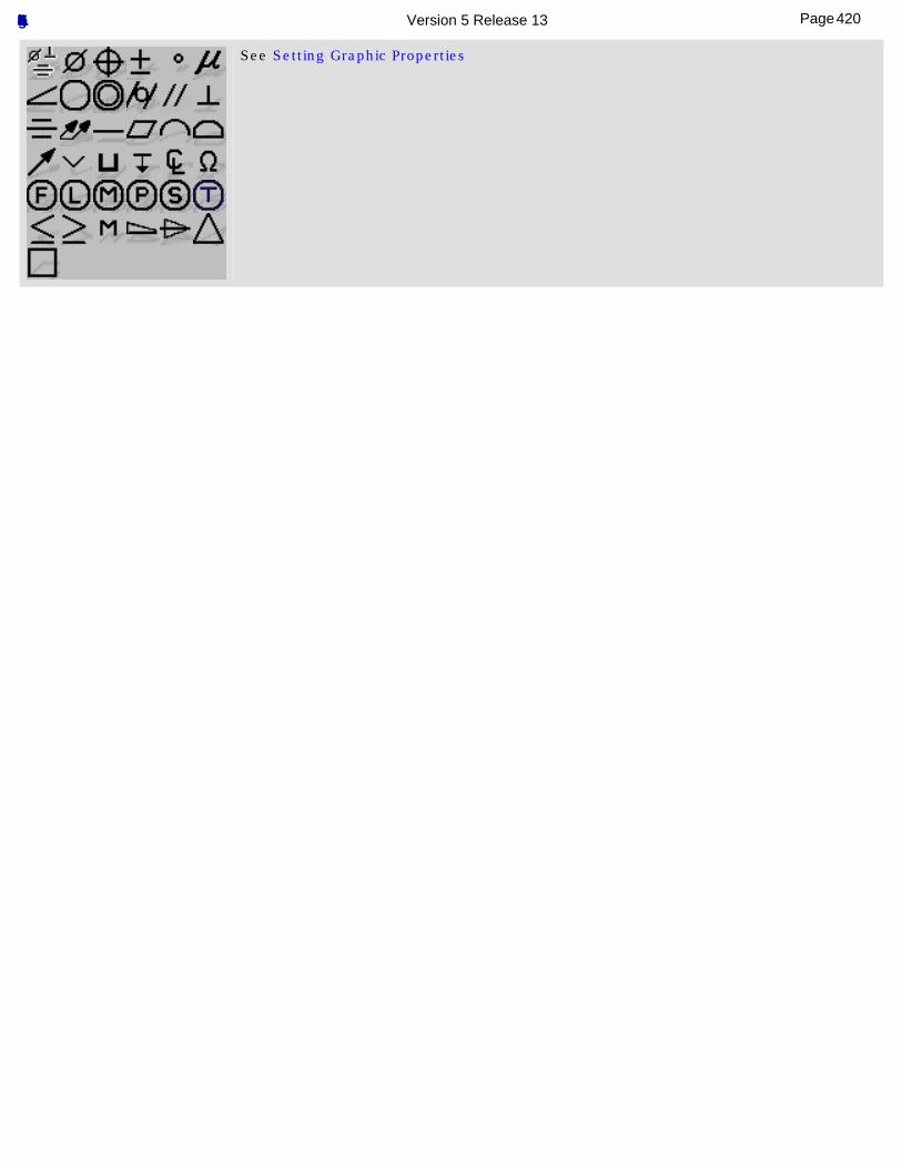
See Setting Graphic Properties
420Page Functional Tolerancing & Annotation Version 5 Release 13
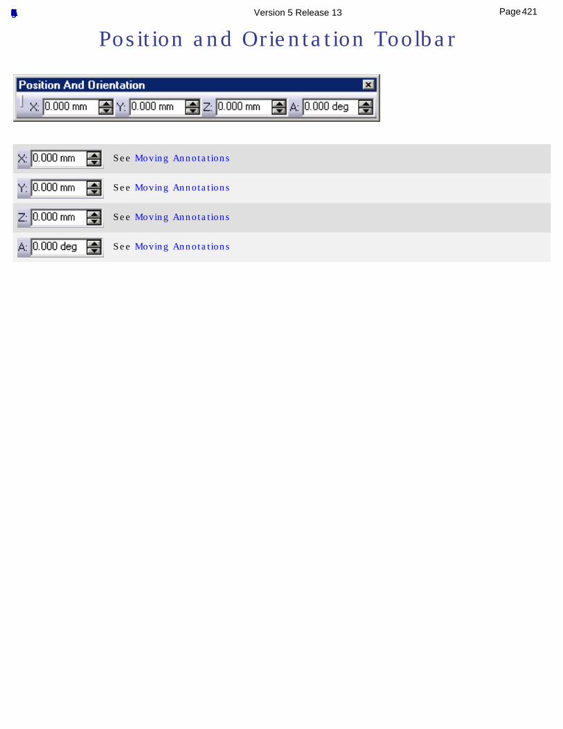
Position and Orientation Toolbar
See Moving Annotations
See Moving Annotations
See Moving Annotations
See Moving Annotations
421Page Functional Tolerancing & Annotation Version 5 Release 13

Views/Annotation Planes Toolbar
Jump to Views Sub-Toolbar
Views Sub-Toolbar
See Creating a Projection View/Annotation Plane
See Creating a Section View/Annotation Plane
See Creating a Section Cut View/Annotation Plane
See Creating an Offset Section View/Section Cut
See See Creating an Aligned Section View/Section Cut
422Page Functional Tolerancing & Annotation Version 5 Release 13
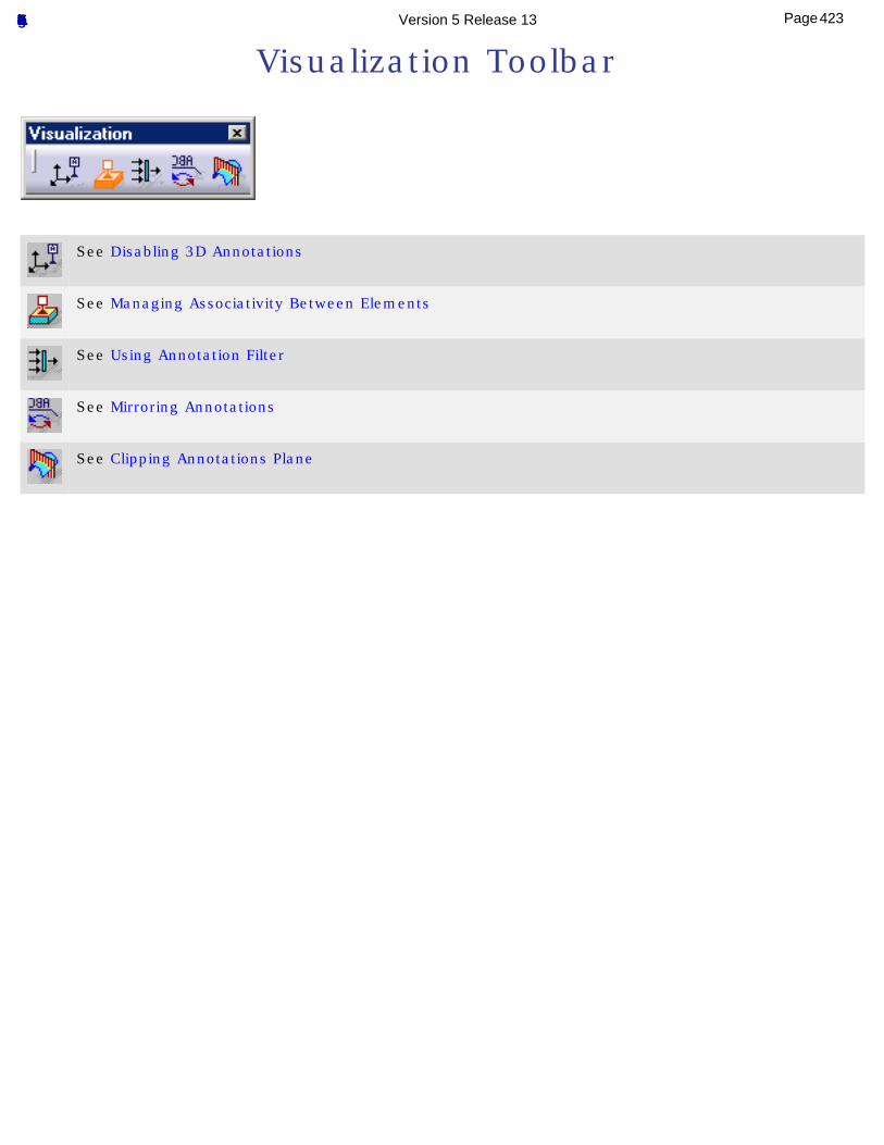
Visualization Toolbar
See Disabling 3D Annotations
See Managing Associativity Between Elements
See Using Annotation Filter
See Mirroring Annotations
See Clipping Annotations Plane
423Page Functional Tolerancing & Annotation Version 5 Release 13
Note Object Attribute Toolbar
See Creating Note Object Attribute
424Page Functional Tolerancing & Annotation Version 5 Release 13
3D Grid Toolbar
See Using 3D Grid
See Using 3D Grid
425Page Functional Tolerancing & Annotation Version 5 Release 13
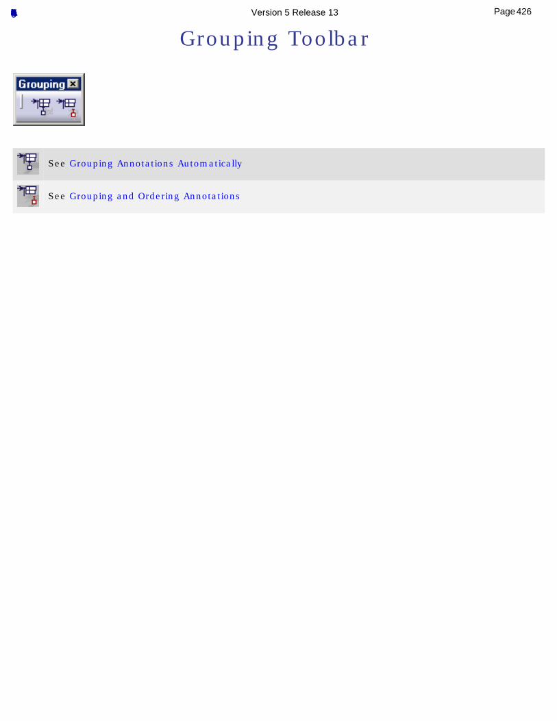
Grouping Toolbar
See Grouping Annotations Automatically
See Grouping and Ordering Annotations
426Page Functional Tolerancing & Annotation Version 5 Release 13
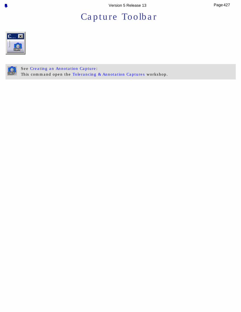
Capture Toolbar
See Creating an Annotation Capture: This command open the Tolerancing & Annotation Captures workshop.
427Page Functional Tolerancing & Annotation Version 5 Release 13
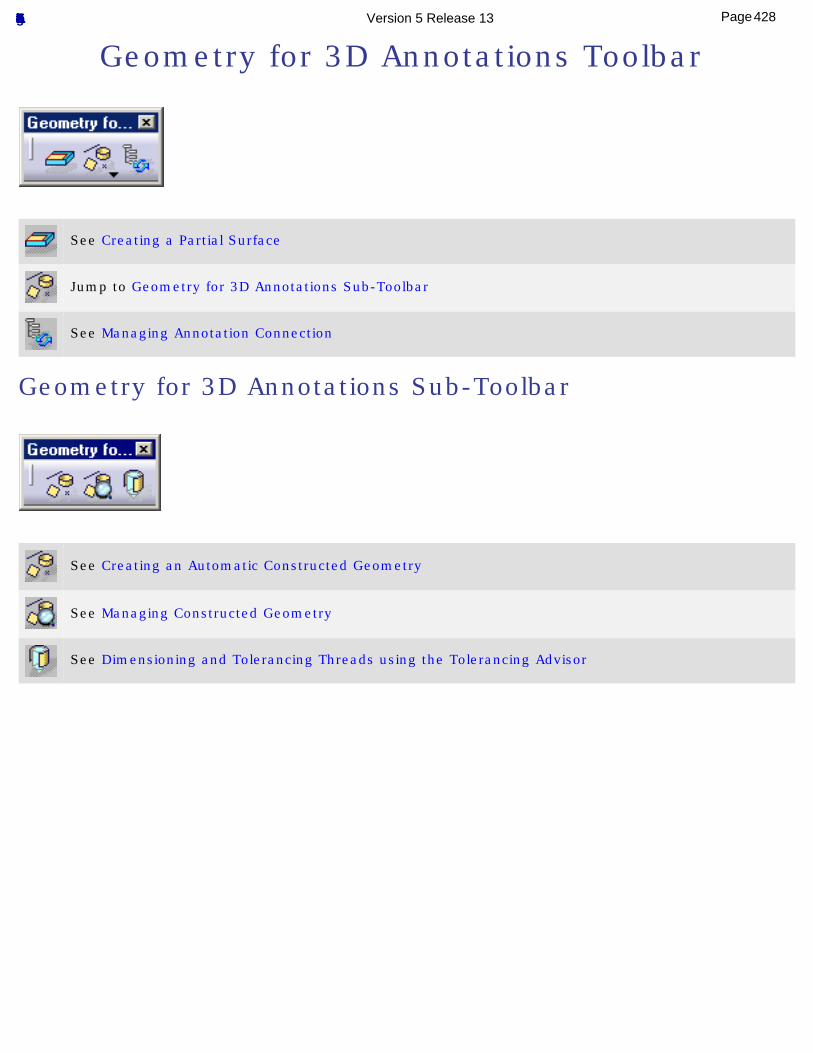
Geometry for 3D Annotations Toolbar
See Creating a Partial Surface
Jump to Geometry for 3D Annotations Sub-Toolbar
See Managing Annotation Connection
Geometry for 3D Annotations Sub-Toolbar
See Creating an Automatic Constructed Geometry
See Managing Constructed Geometry
See Dimensioning and Tolerancing Threads using the Tolerancing Advisor
428Page Functional Tolerancing & Annotation Version 5 Release 13
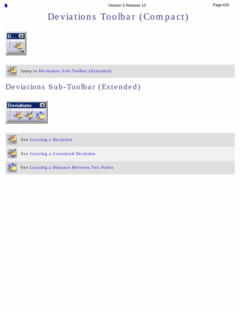
Deviations Toolbar (Compact)
Jump to Deviations Sub-Toolbar (Extended)
Deviations Sub-Toolbar (Extended)
See Creating a Deviation
See Creating a Correlated Deviation
See Creating a Distance Between Two Points
429Page Functional Tolerancing & Annotation Version 5 Release 13
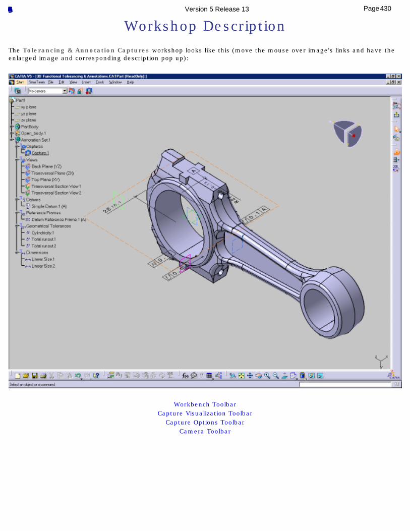
Workshop DescriptionThe Tolerancing & Annotation Captures workshop looks like this (move the mouse over image's links and have the enlarged image and corresponding description pop up):
Workbench ToolbarCapture Visualization Toolbar
Capture Options ToolbarCamera Toolbar
430Page Functional Tolerancing & Annotation Version 5 Release 13
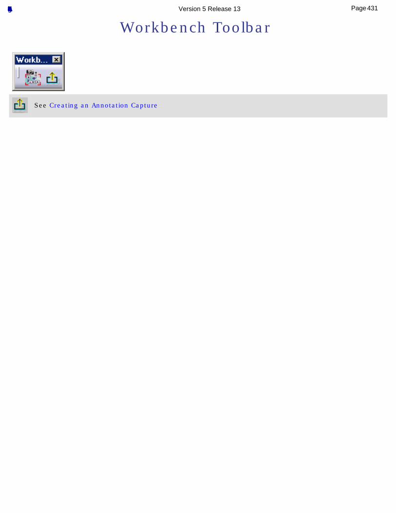
Workbench Toolbar
See Creating an Annotation Capture
431Page Functional Tolerancing & Annotation Version 5 Release 13
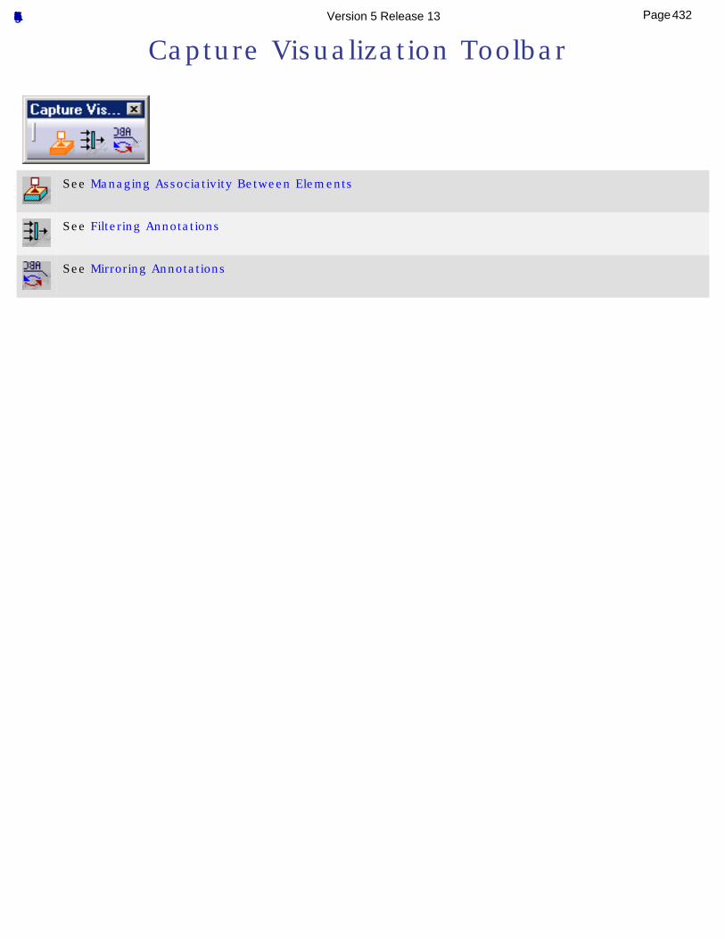
Capture Visualization Toolbar
See Managing Associativity Between Elements
See Filtering Annotations
See Mirroring Annotations
432Page Functional Tolerancing & Annotation Version 5 Release 13
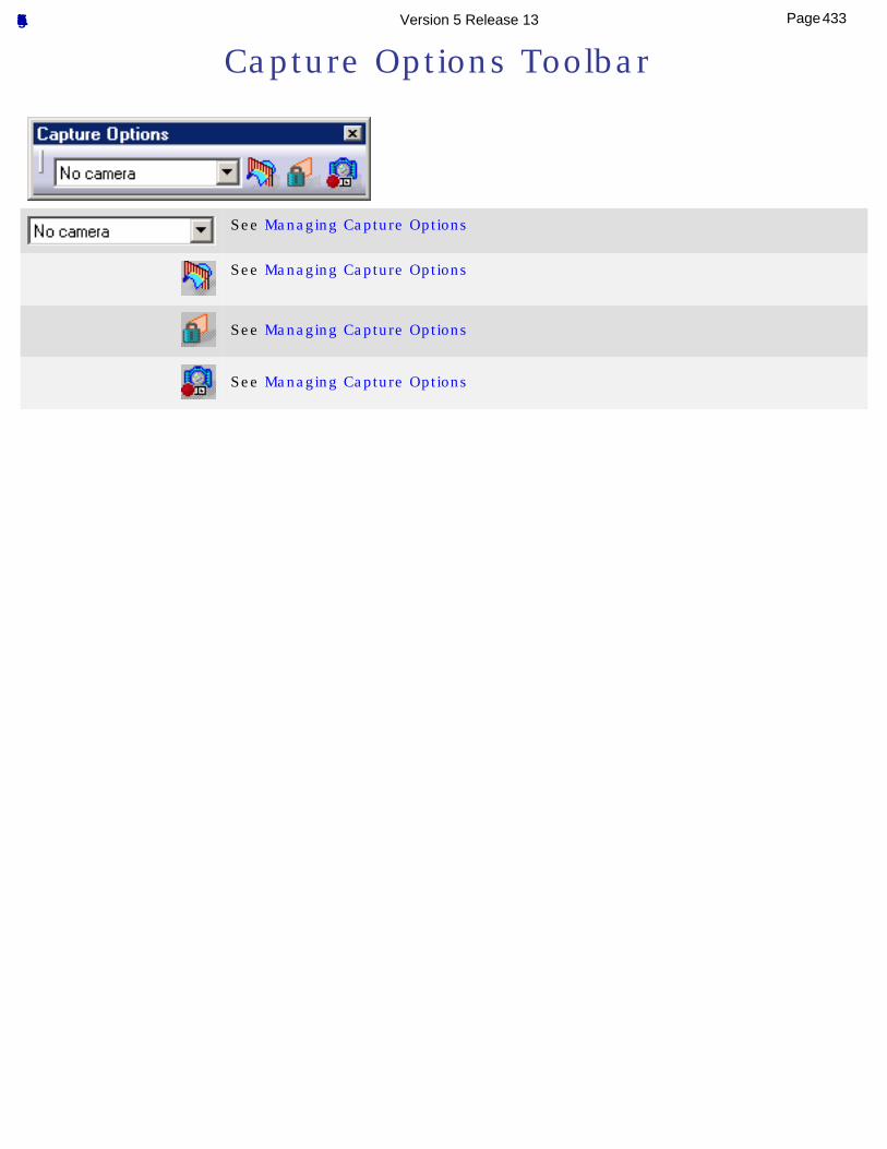
Capture Options Toolbar
See Managing Capture Options
See Managing Capture Options
See Managing Capture Options
See Managing Capture Options
433Page Functional Tolerancing & Annotation Version 5 Release 13
Camera Toolbar
See Creating a Camera
434Page Functional Tolerancing & Annotation Version 5 Release 13
Customizing for 3D Functional Tolerancing & Annotation
This section describes the various settings you can customize for 3D Functional Tolerancing & Annotations via the Tools -> Options command.
TolerancingDisplayConstructed GeometryManipulatorsDimensionAnnotationTolerance ValuesView/Annotation Plane
435Page Functional Tolerancing & Annotation Version 5 Release 13
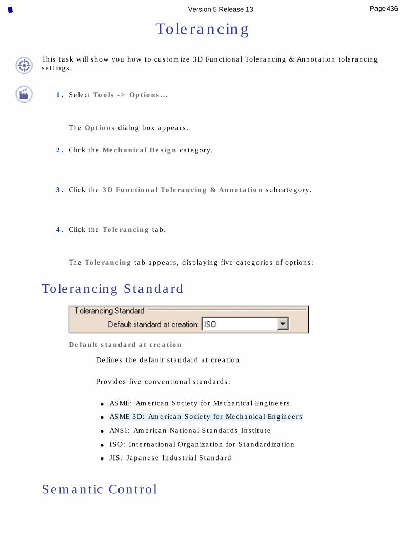
Tolerancing
This task will show you how to customize 3D Functional Tolerancing & Annotation tolerancing settings.
1. Select Tools -> Options...
The Options dialog box appears.
2. Click the Mechanical Design category.
3. Click the 3D Functional Tolerancing & Annotation subcategory.
4. Click the Tolerancing tab.
The Tolerancing tab appears, displaying five categories of options:
Tolerancing Standard
Default standard at creation
Defines the default standard at creation.
Provides five conventional standards:
● ASME: American Society for Mechanical Engineers
● ASME 3D: American Society for Mechanical Engineers
● ANSI: American National Standards Institute
● ISO: International Organization for Standardization
● JIS: Japanese Industrial Standard
Semantic Control
436Page Functional Tolerancing & Annotation Version 5 Release 13
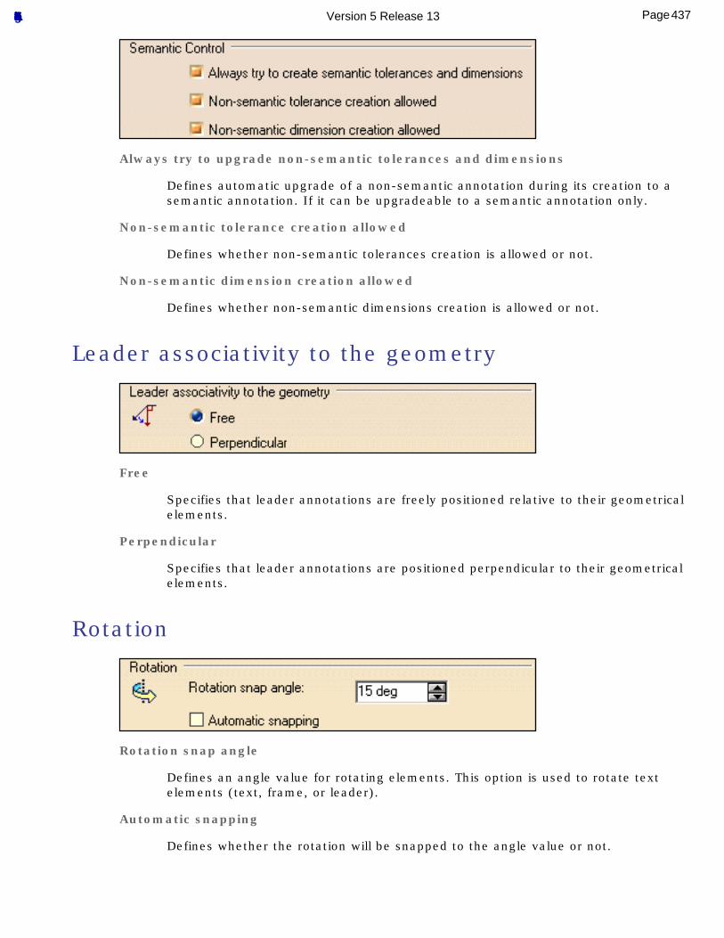
Always try to upgrade non-semantic tolerances and dimensions
Defines automatic upgrade of a non-semantic annotation during its creation to a semantic annotation. If it can be upgradeable to a semantic annotation only.
Non-semantic tolerance creation allowed
Defines whether non-semantic tolerances creation is allowed or not.
Non-semantic dimension creation allowed
Defines whether non-semantic dimensions creation is allowed or not.
Leader associativity to the geometry
Free
Specifies that leader annotations are freely positioned relative to their geometrical elements.
Perpendicular
Specifies that leader annotations are positioned perpendicular to their geometrical elements.
Rotation
Rotation snap angle
Defines an angle value for rotating elements. This option is used to rotate text elements (text, frame, or leader).
Automatic snapping
Defines whether the rotation will be snapped to the angle value or not.
437Page Functional Tolerancing & Annotation Version 5 Release 13
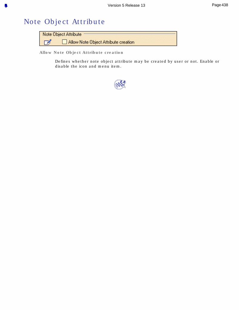
Note Object Attribute
Allow Note Object Attribute creation
Defines whether note object attribute may be created by user or not. Enable or disable the icon and menu item.
438Page Functional Tolerancing & Annotation Version 5 Release 13
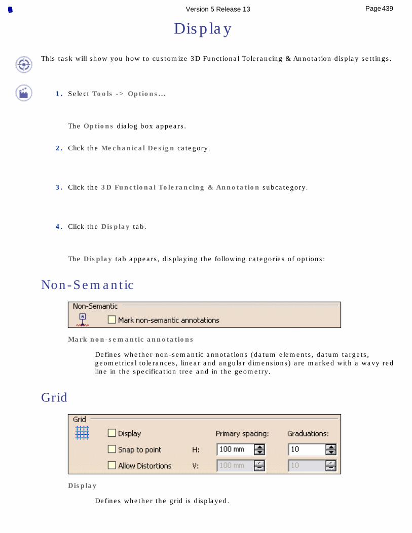
Display
This task will show you how to customize 3D Functional Tolerancing & Annotation display settings.
1. Select Tools -> Options...
The Options dialog box appears.
2. Click the Mechanical Design category.
3. Click the 3D Functional Tolerancing & Annotation subcategory.
4. Click the Display tab.
The Display tab appears, displaying the following categories of options:
Non-Semantic
Mark non-semantic annotations
Defines whether non-semantic annotations (datum elements, datum targets, geometrical tolerances, linear and angular dimensions) are marked with a wavy red line in the specification tree and in the geometry.
Grid
Display
Defines whether the grid is displayed.
439Page Functional Tolerancing & Annotation Version 5 Release 13
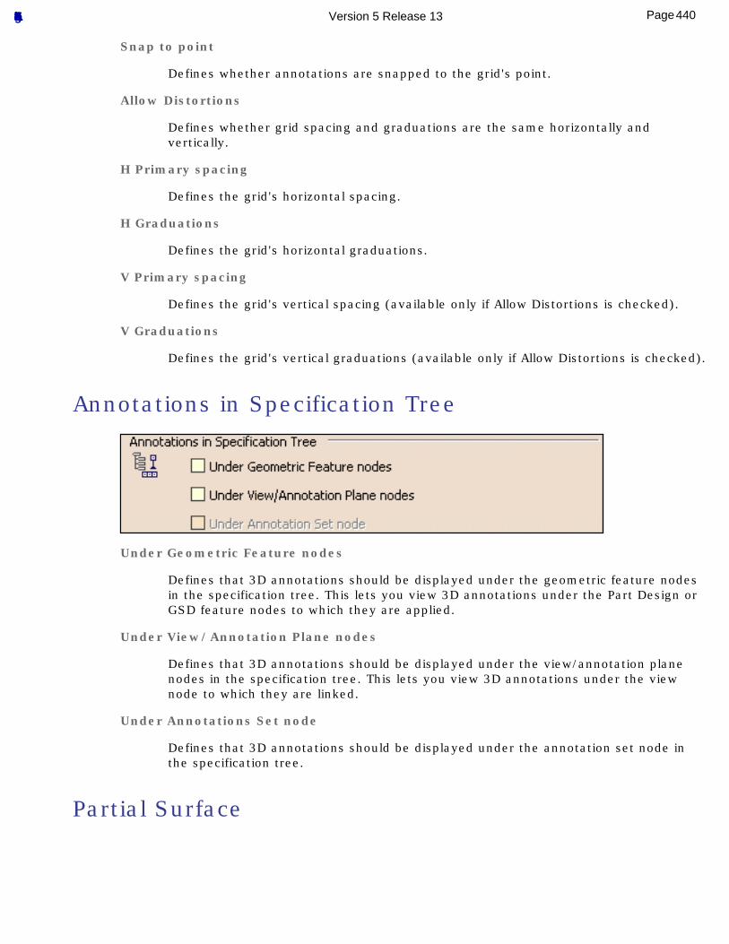
Snap to point
Defines whether annotations are snapped to the grid's point.
Allow Distortions
Defines whether grid spacing and graduations are the same horizontally and vertically.
H Primary spacing
Defines the grid's horizontal spacing.
H Graduations
Defines the grid's horizontal graduations.
V Primary spacing
Defines the grid's vertical spacing (available only if Allow Distortions is checked).
V Graduations
Defines the grid's vertical graduations (available only if Allow Distortions is checked).
Annotations in Specification Tree
Under Geometric Feature nodes
Defines that 3D annotations should be displayed under the geometric feature nodes in the specification tree. This lets you view 3D annotations under the Part Design or GSD feature nodes to which they are applied.
Under View/Annotation Plane nodes
Defines that 3D annotations should be displayed under the view/annotation plane nodes in the specification tree. This lets you view 3D annotations under the view node to which they are linked.
Under Annotations Set node
Defines that 3D annotations should be displayed under the annotation set node in the specification tree.
Partial Surface
440Page Functional Tolerancing & Annotation Version 5 Release 13
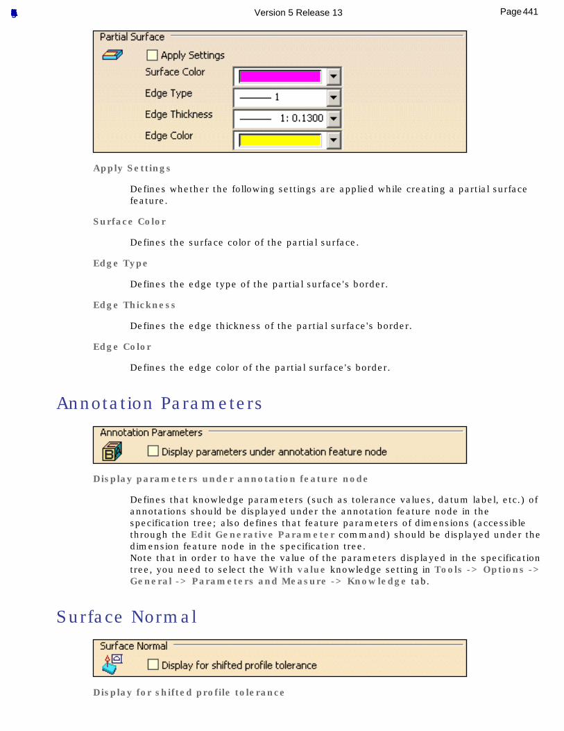
Apply Settings
Defines whether the following settings are applied while creating a partial surface feature.
Surface Color
Defines the surface color of the partial surface.
Edge Type
Defines the edge type of the partial surface's border.
Edge Thickness
Defines the edge thickness of the partial surface's border.
Edge Color
Defines the edge color of the partial surface's border.
Annotation Parameters
Display parameters under annotation feature node
Defines that knowledge parameters (such as tolerance values, datum label, etc.) of annotations should be displayed under the annotation feature node in the specification tree; also defines that feature parameters of dimensions (accessible through the Edit Generative Parameter command) should be displayed under the dimension feature node in the specification tree.Note that in order to have the value of the parameters displayed in the specification tree, you need to select the With value knowledge setting in Tools -> Options -> General -> Parameters and Measure -> Knowledge tab.
Surface Normal
Display for shifted profile tolerance
441Page Functional Tolerancing & Annotation Version 5 Release 13
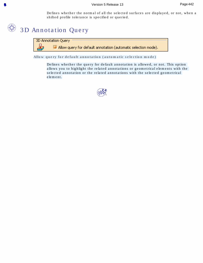
Defines whether the normal of all the selected surfaces are displayed, or not, when a shifted profile tolerance is specified or queried.
3D Annotation Query
Allow query for default annotation (automatic selection mode)
Defines whether the query for default annotation is allowed, or not. This option allows you to highlight the related annotations or geometrical elements with the selected annotation or the related annotations with the selected geometrical element.
442Page Functional Tolerancing & Annotation Version 5 Release 13
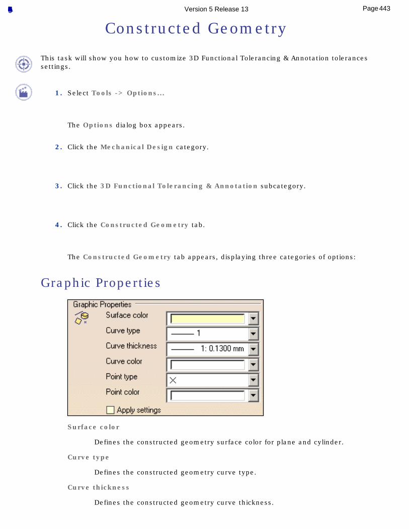
Constructed Geometry
This task will show you how to customize 3D Functional Tolerancing & Annotation tolerances settings.
1. Select Tools -> Options...
The Options dialog box appears.
2. Click the Mechanical Design category.
3. Click the 3D Functional Tolerancing & Annotation subcategory.
4. Click the Constructed Geometry tab.
The Constructed Geometry tab appears, displaying three categories of options:
Graphic Properties
Surface color
Defines the constructed geometry surface color for plane and cylinder.
Curve type
Defines the constructed geometry curve type.
Curve thickness
Defines the constructed geometry curve thickness.
443Page Functional Tolerancing & Annotation Version 5 Release 13
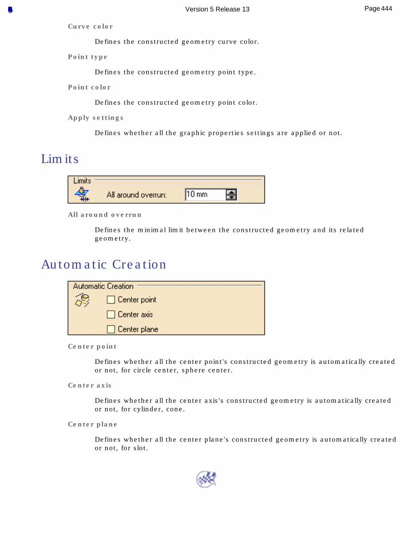
Curve color
Defines the constructed geometry curve color.
Point type
Defines the constructed geometry point type.
Point color
Defines the constructed geometry point color.
Apply settings
Defines whether all the graphic properties settings are applied or not.
Limits
All around overrun
Defines the minimal limit between the constructed geometry and its related geometry.
Automatic Creation
Center point
Defines whether all the center point's constructed geometry is automatically created or not, for circle center, sphere center.
Center axis
Defines whether all the center axis's constructed geometry is automatically created or not, for cylinder, cone.
Center plane
Defines whether all the center plane's constructed geometry is automatically created or not, for slot.
444Page Functional Tolerancing & Annotation Version 5 Release 13
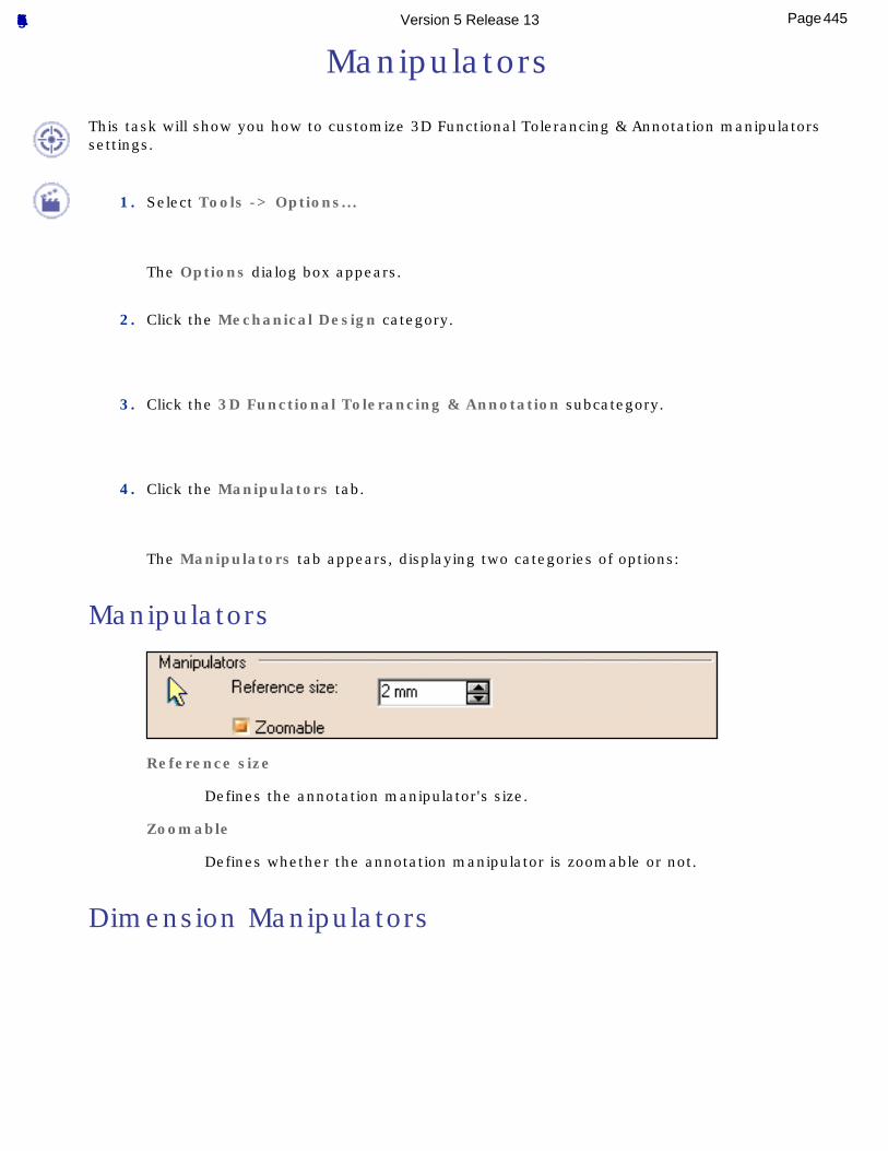
Manipulators
This task will show you how to customize 3D Functional Tolerancing & Annotation manipulators settings.
1. Select Tools -> Options...
The Options dialog box appears.
2. Click the Mechanical Design category.
3. Click the 3D Functional Tolerancing & Annotation subcategory.
4. Click the Manipulators tab.
The Manipulators tab appears, displaying two categories of options:
Manipulators
Reference size
Defines the annotation manipulator's size.
Zoomable
Defines whether the annotation manipulator is zoomable or not.
Dimension Manipulators
445Page Functional Tolerancing & Annotation Version 5 Release 13
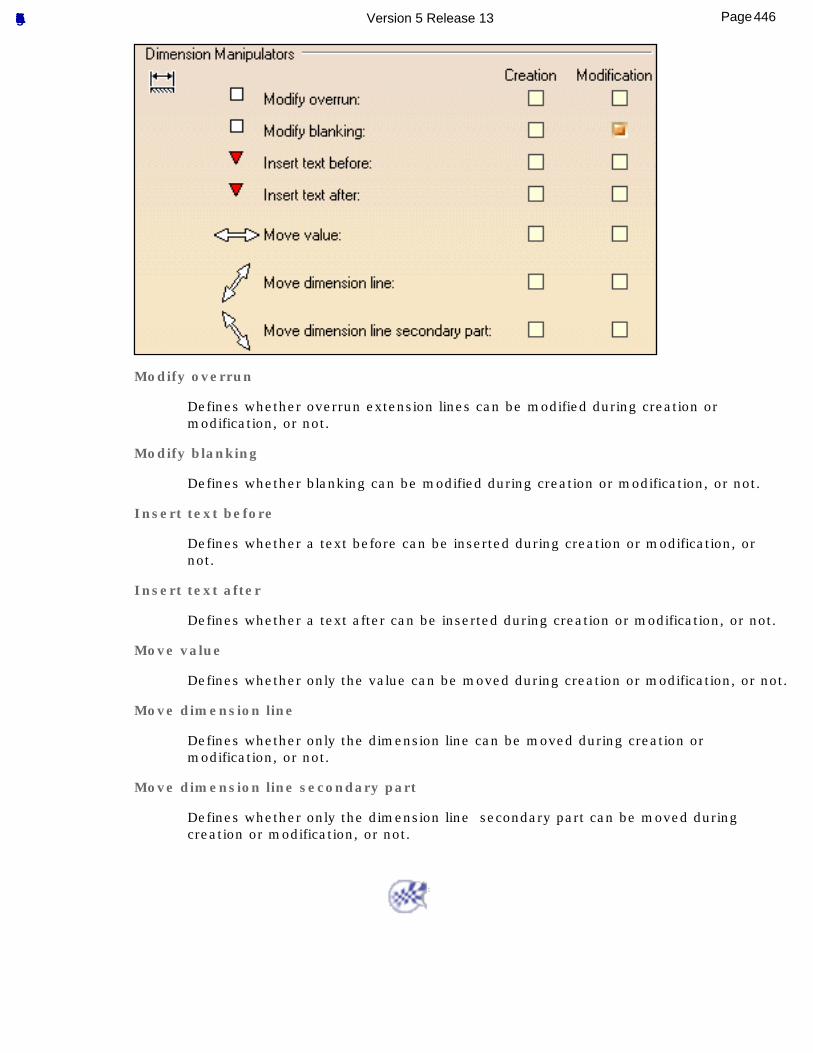
Modify overrun
Defines whether overrun extension lines can be modified during creation or modification, or not.
Modify blanking
Defines whether blanking can be modified during creation or modification, or not.
Insert text before
Defines whether a text before can be inserted during creation or modification, or not.
Insert text after
Defines whether a text after can be inserted during creation or modification, or not.
Move value
Defines whether only the value can be moved during creation or modification, or not.
Move dimension line
Defines whether only the dimension line can be moved during creation or modification, or not.
Move dimension line secondary part
Defines whether only the dimension line secondary part can be moved during creation or modification, or not.
446Page Functional Tolerancing & Annotation Version 5 Release 13
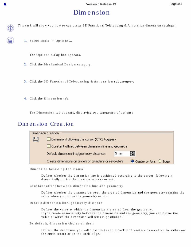
Dimension
This task will show you how to customize 3D Functional Tolerancing & Annotation dimension settings.
1. Select Tools -> Options...
The Options dialog box appears.
2. Click the Mechanical Design category.
3. Click the 3D Functional Tolerancing & Annotation subcategory.
4. Click the Dimension tab.
The Dimension tab appears, displaying two categories of options:
Dimension Creation
Dimension following the mouse
Defines whether the dimension line is positioned according to the cursor, following it dynamically during the creation process or not.
Constant offset between dimension line and geometry
Defines whether the distance between the created dimension and the geometry remains the same when you move the geometry or not.
Default dimension line/geometry distance
Defines the value at which the dimension is created from the geometry.If you create associativity between the dimension and the geometry, you can define the value at which the dimension will remain positioned.
By default, dimension circles on their
Defines the dimension you will create between a circle and another element will be either on the circle center or on the circle edge.
447Page Functional Tolerancing & Annotation Version 5 Release 13
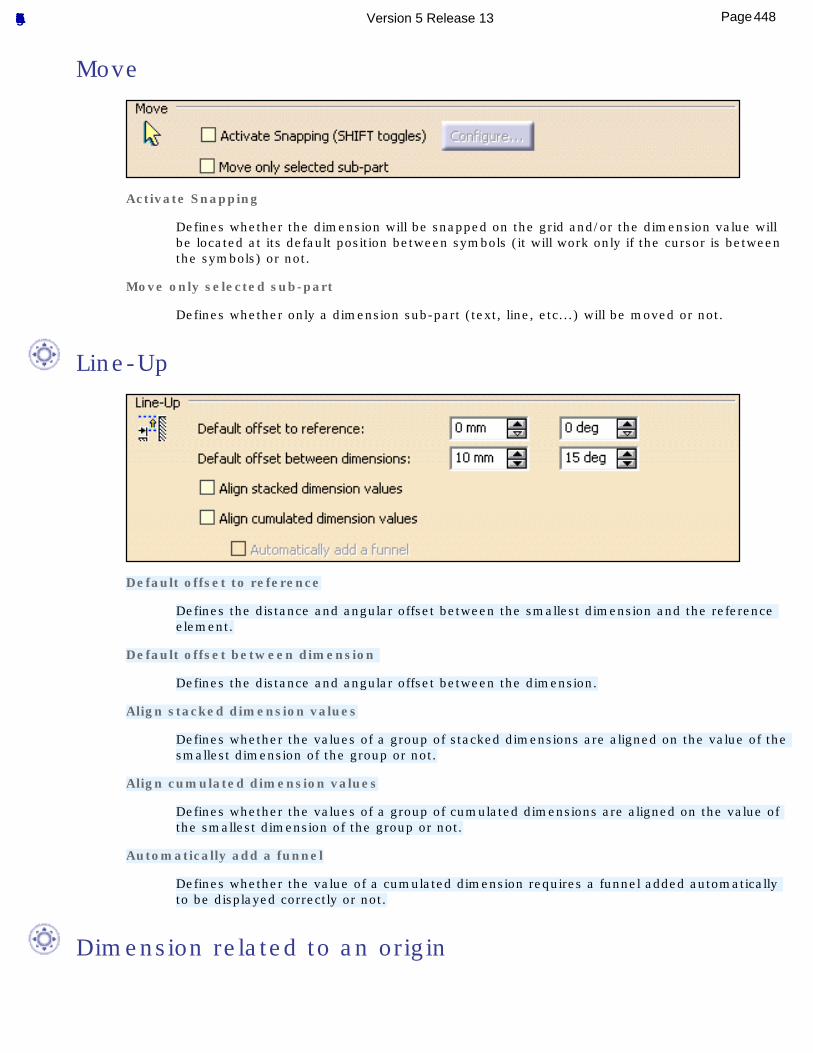
Move
Activate Snapping
Defines whether the dimension will be snapped on the grid and/or the dimension value will be located at its default position between symbols (it will work only if the cursor is between the symbols) or not.
Move only selected sub-part
Defines whether only a dimension sub-part (text, line, etc...) will be moved or not.
Line-Up
Default offset to reference
Defines the distance and angular offset between the smallest dimension and the reference element.
Default offset between dimension
Defines the distance and angular offset between the dimension.
Align stacked dimension values
Defines whether the values of a group of stacked dimensions are aligned on the value of the smallest dimension of the group or not.
Align cumulated dimension values
Defines whether the values of a group of cumulated dimensions are aligned on the value of the smallest dimension of the group or not.
Automatically add a funnel
Defines whether the value of a cumulated dimension requires a funnel added automatically to be displayed correctly or not.
Dimension related to an origin
448Page Functional Tolerancing & Annotation Version 5 Release 13
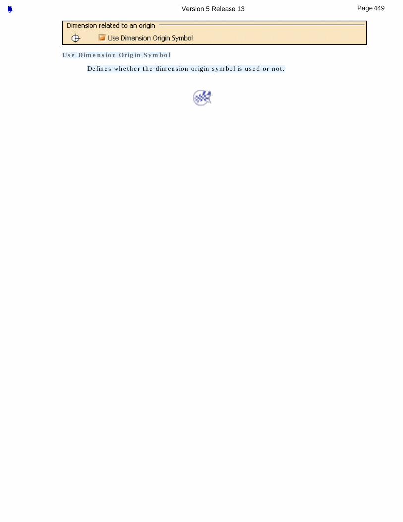
Use Dimension Origin Symbol
Defines whether the dimension origin symbol is used or not.
449Page Functional Tolerancing & Annotation Version 5 Release 13
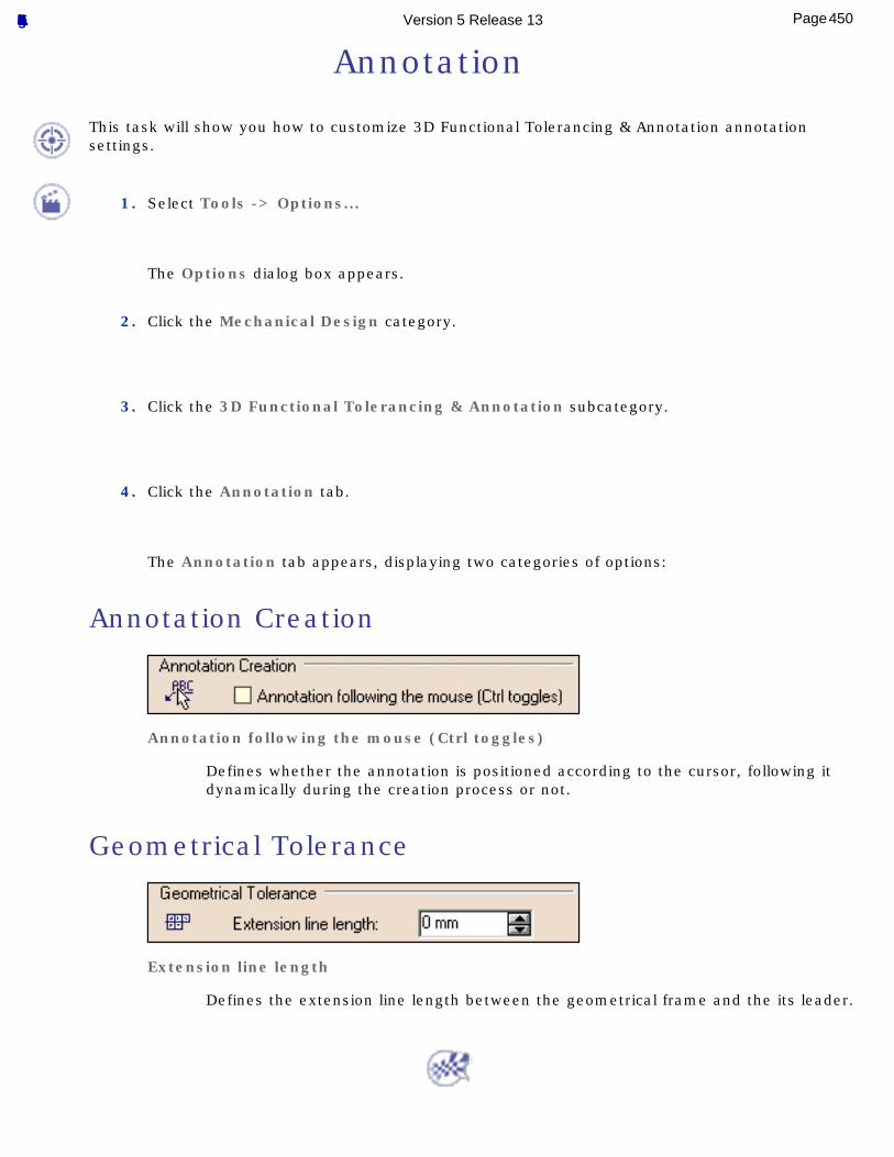
Annotation
This task will show you how to customize 3D Functional Tolerancing & Annotation annotation settings.
1. Select Tools -> Options...
The Options dialog box appears.
2. Click the Mechanical Design category.
3. Click the 3D Functional Tolerancing & Annotation subcategory.
4. Click the Annotation tab.
The Annotation tab appears, displaying two categories of options:
Annotation Creation
Annotation following the mouse (Ctrl toggles)
Defines whether the annotation is positioned according to the cursor, following it dynamically during the creation process or not.
Geometrical Tolerance
Extension line length
Defines the extension line length between the geometrical frame and the its leader.
450Page Functional Tolerancing & Annotation Version 5 Release 13
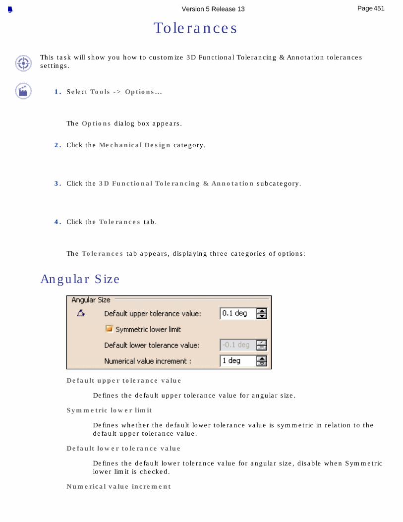
Tolerances
This task will show you how to customize 3D Functional Tolerancing & Annotation tolerances settings.
1. Select Tools -> Options...
The Options dialog box appears.
2. Click the Mechanical Design category.
3. Click the 3D Functional Tolerancing & Annotation subcategory.
4. Click the Tolerances tab.
The Tolerances tab appears, displaying three categories of options:
Angular Size
Default upper tolerance value
Defines the default upper tolerance value for angular size.
Symmetric lower limit
Defines whether the default lower tolerance value is symmetric in relation to the default upper tolerance value.
Default lower tolerance value
Defines the default lower tolerance value for angular size, disable when Symmetric lower limit is checked.
Numerical value increment
451Page Functional Tolerancing & Annotation Version 5 Release 13
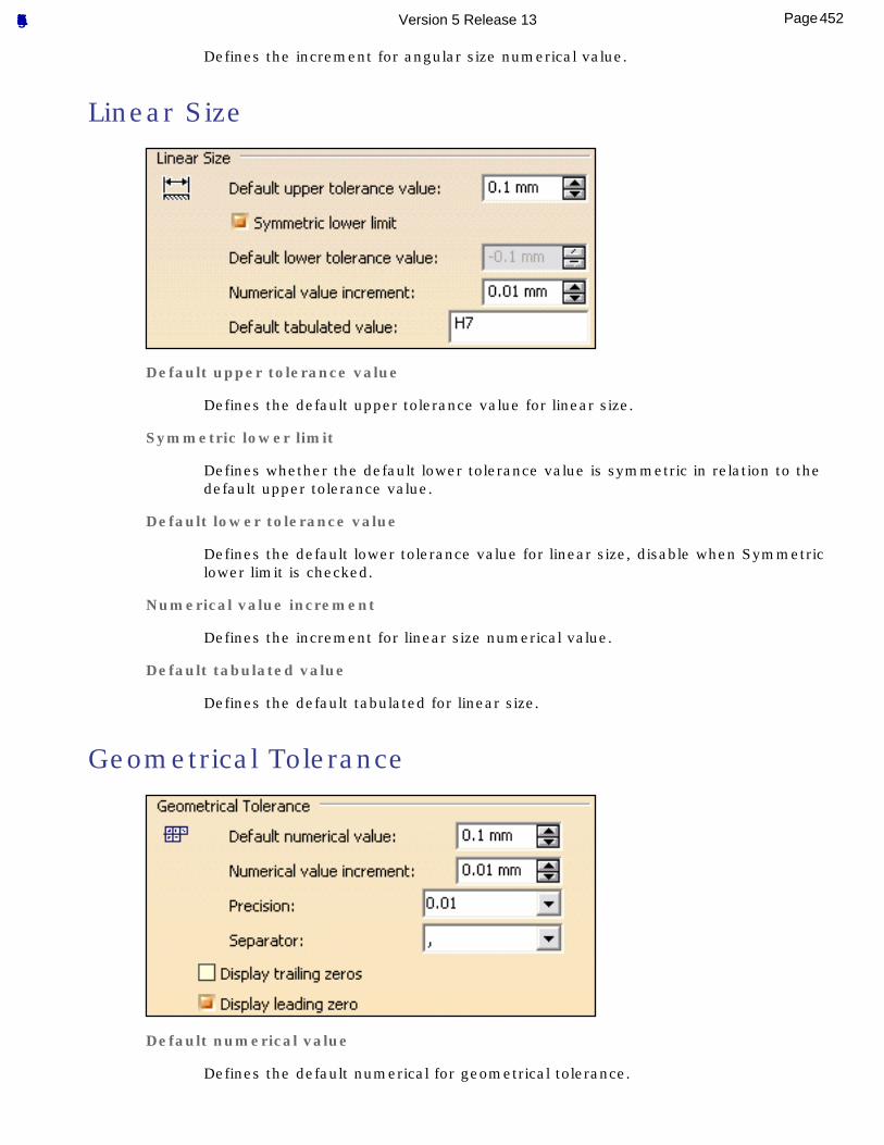
Defines the increment for angular size numerical value.
Linear Size
Default upper tolerance value
Defines the default upper tolerance value for linear size.
Symmetric lower limit
Defines whether the default lower tolerance value is symmetric in relation to the default upper tolerance value.
Default lower tolerance value
Defines the default lower tolerance value for linear size, disable when Symmetric lower limit is checked.
Numerical value increment
Defines the increment for linear size numerical value.
Default tabulated value
Defines the default tabulated for linear size.
Geometrical Tolerance
Default numerical value
Defines the default numerical for geometrical tolerance.
452Page Functional Tolerancing & Annotation Version 5 Release 13
Numerical value increment
Defines the increment for the to geometrical tolerance numerical value.
Precision
Defines the geometrical tolerance precision after the numerical separator.
Separator
Defines the geometrical tolerance symbol used as numerical separator.
Display trailing zeros
Defines whether "0"s complete the number of digit displayed after the separator, according to the precision, or not.
Display leading zeros
Defines whether the "0" before the numerical separator, when value is less than 1, is displayed or not.
453Page Functional Tolerancing & Annotation Version 5 Release 13
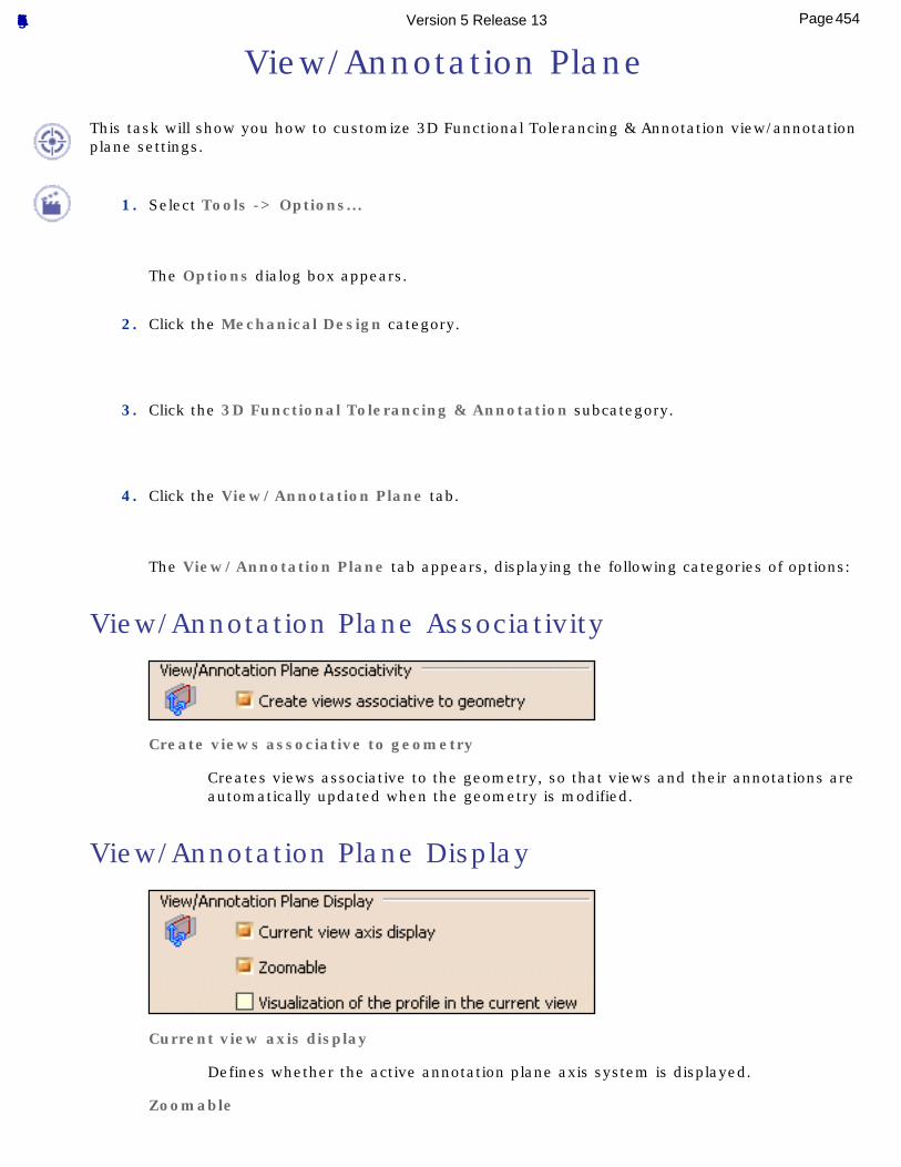
View/Annotation Plane
This task will show you how to customize 3D Functional Tolerancing & Annotation view/annotation plane settings.
1. Select Tools -> Options...
The Options dialog box appears.
2. Click the Mechanical Design category.
3. Click the 3D Functional Tolerancing & Annotation subcategory.
4. Click the View/Annotation Plane tab.
The View/Annotation Plane tab appears, displaying the following categories of options:
View/Annotation Plane Associativity
Create views associative to geometry
Creates views associative to the geometry, so that views and their annotations are automatically updated when the geometry is modified.
View/Annotation Plane Display
Current view axis display
Defines whether the active annotation plane axis system is displayed.
Zoomable
454Page Functional Tolerancing & Annotation Version 5 Release 13
Defines whether the annotation plane axis is zoomable.
Visualization of the profile in the current view
Defines whether the view/annotation plane profile on the part/product is displayed or not.
455Page Functional Tolerancing & Annotation Version 5 Release 13
Reference InformationThis section contains reference information about 3D Functional Tolerancing & Annotations workbench.
StandardsSemantic Support
Normative ReferencesPrinciples and Fundamental Rules for Geometrical Tolerancing
Geometrical TolerancingSymbols for Geometrical Tolerances
Symbols for ModifiersDatum Principles
ConceptsProperties
Dimension UnitsStatistic Laws
456Page Functional Tolerancing & Annotation Version 5 Release 13
Standards
Standards (such as ISO, JIS, ANSI, ASME, etc. or company standards) specify the properties and styles of tolerancing and annotation elements such as dimensions, annotations, etc. so that they will be applied to all elements of a given type within a single part or product, as well as in all parts or products which use the same parent standard.
Standards are managed by an administrator. Each standard is defined in an XML file, which makes it possible to customize globally the appearance and behavior of tolerancing and annotation elements.
Standards in the 3D Functional Tolerancing and Annotation workbench are those used and customized in the Drafting workbenches: they are 2D standards, transposed to 3D. As they are defined for the Drafting workbenches, some standard parameters apply only to Drafting applications. However, a great number of parameters apply to both the 3D Functional Tolerancing and Annotation and Drafting workbenches.
The values of the parameters in the file are taken into account when the first Functional Tolerancing and Annotation view is created, based on the current parent standard. Once the first view has been created, modifying the standard file will not affect this CATPart document.
For more information on standards and their administration, refer to the User Tasks > Administration Tasks chapter in the Interactive Drafting User's Guide.
Dimension Tolerance Display
Dimension Numerical Display
457Page Functional Tolerancing & Annotation Version 5 Release 13
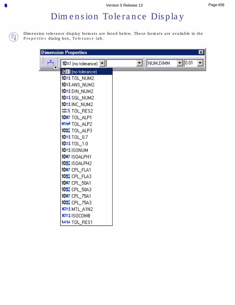
Dimension Tolerance Display
Dimension tolerance display formats are listed below. These formats are available in the Properties dialog box, Tolerance tab.
458Page Functional Tolerancing & Annotation Version 5 Release 13
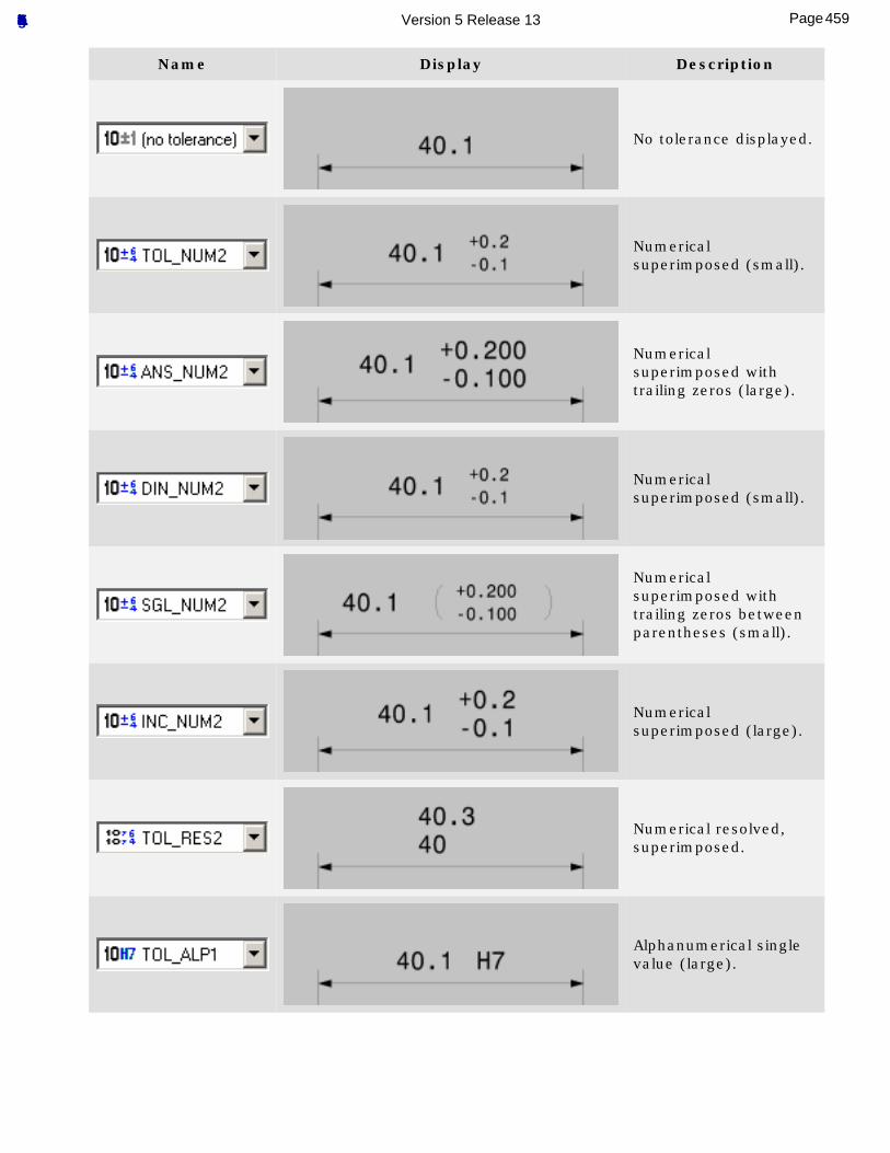
Name Display Description
No tolerance displayed.
Numerical superimposed (small).
Numerical superimposed with trailing zeros (large).
Numerical superimposed (small).
Numerical superimposed with trailing zeros between parentheses (small).
Numerical superimposed (large).
Numerical resolved, superimposed.
Alphanumerical single value (large).
459Page Functional Tolerancing & Annotation Version 5 Release 13
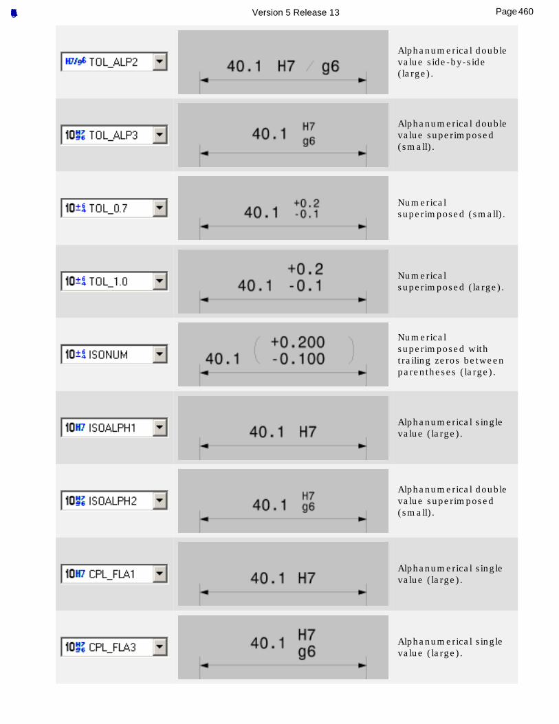
Alphanumerical double value side-by-side (large).
Alphanumerical double value superimposed (small).
Numerical superimposed (small).
Numerical superimposed (large).
Numerical superimposed with trailing zeros between parentheses (large).
Alphanumerical single value (large).
Alphanumerical double value superimposed (small).
Alphanumerical single value (large).
Alphanumerical single value (large).
460Page Functional Tolerancing & Annotation Version 5 Release 13
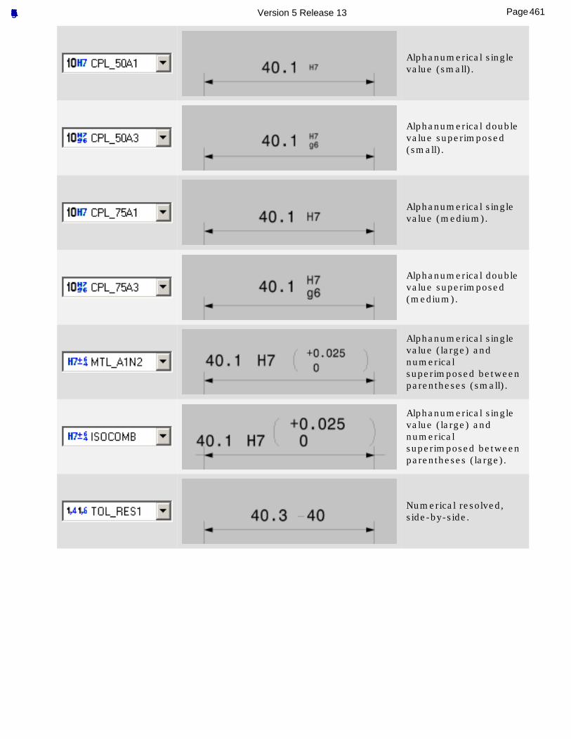
Alphanumerical single value (small).
Alphanumerical double value superimposed (small).
Alphanumerical single value (medium).
Alphanumerical double value superimposed (medium).
Alphanumerical single value (large) and numerical superimposed between parentheses (small).
Alphanumerical single value (large) and numerical superimposed between parentheses (large).
Numerical resolved, side-by-side.
461Page Functional Tolerancing & Annotation Version 5 Release 13
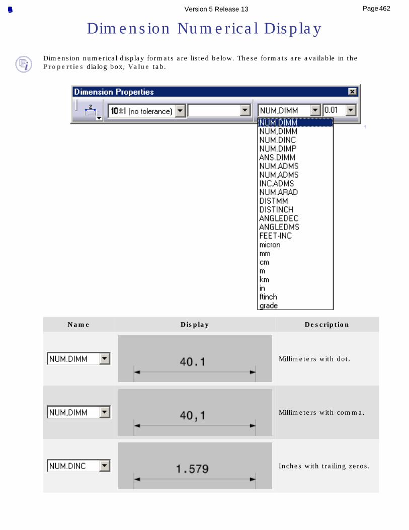
Dimension Numerical Display
Dimension numerical display formats are listed below. These formats are available in the Properties dialog box, Value tab.
Name Display Description
Millimeters with dot.
Millimeters with comma.
Inches with trailing zeros.
462Page Functional Tolerancing & Annotation Version 5 Release 13
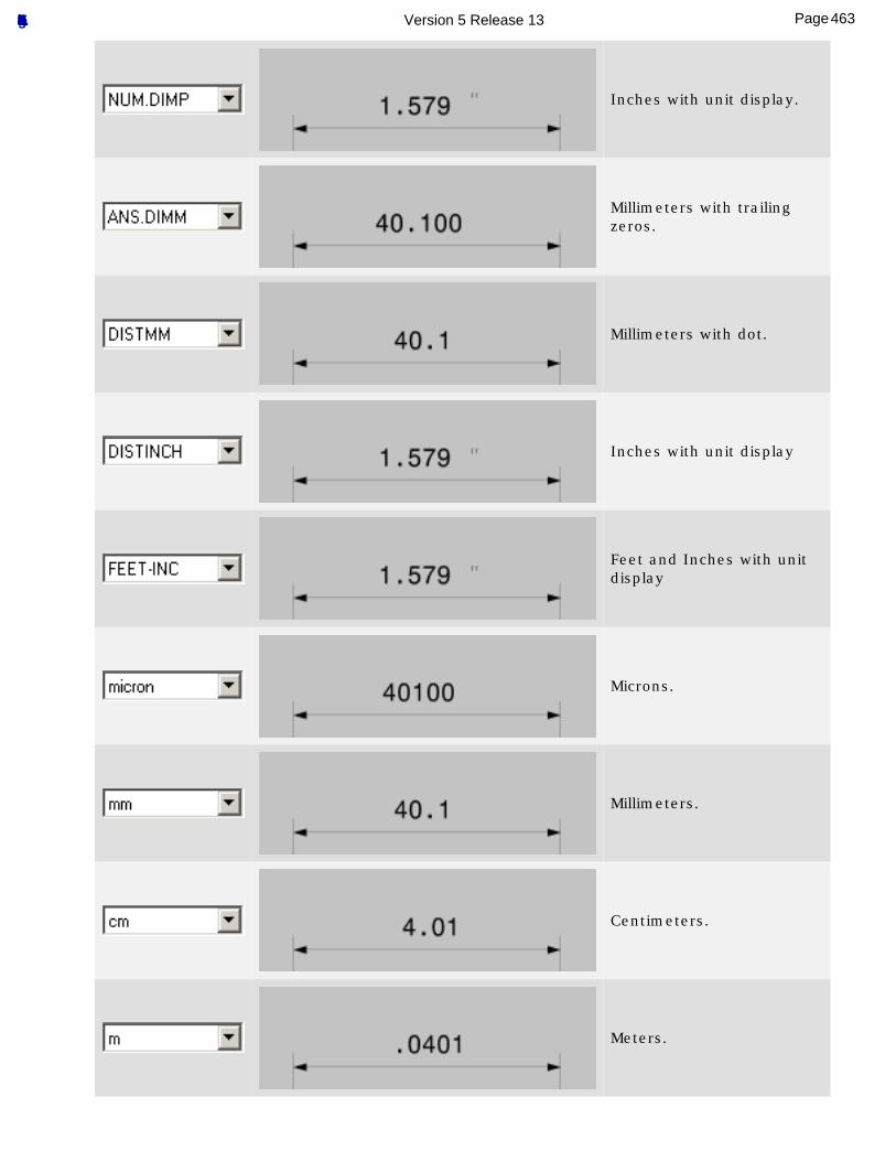
Inches with unit display.
Millimeters with trailing zeros.
Millimeters with dot.
Inches with unit display
Feet and Inches with unit display
Microns.
Millimeters.
Centimeters.
Meters.
463Page Functional Tolerancing & Annotation Version 5 Release 13
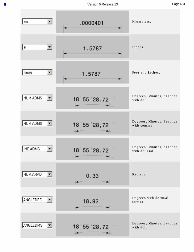
Kilometers.
Inches.
Feet and Inches.
Degrees, Minutes, Seconds with dot.
Degrees, Minutes, Seconds with comma.
Degrees, Minutes, Seconds with dot and
Radians.
Degrees with decimal format.
Degrees, Minutes, Seconds with dot.
464Page Functional Tolerancing & Annotation Version 5 Release 13
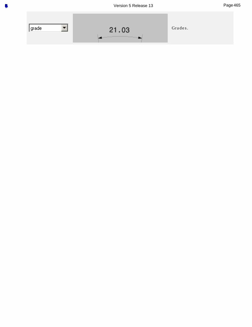
Grades.
465Page Functional Tolerancing & Annotation Version 5 Release 13
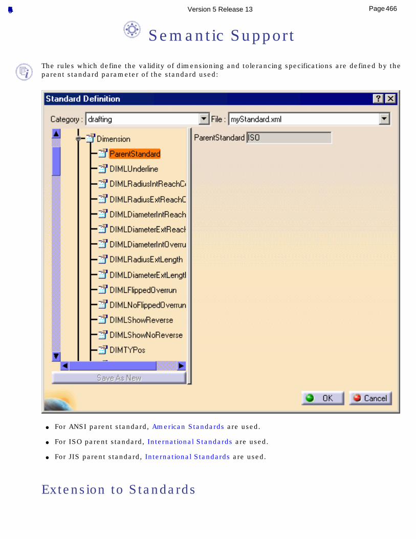
Semantic Support
The rules which define the validity of dimensioning and tolerancing specifications are defined by the parent standard parameter of the standard used:
● For ANSI parent standard, American Standards are used.
● For ISO parent standard, International Standards are used.
● For JIS parent standard, International Standards are used.
Extension to Standards
466Page Functional Tolerancing & Annotation Version 5 Release 13
● For ANSI and ISO standards:
❍ Oriented Dimension: capability to create semantic toleranced dimensions on non-Features of Size (between planar face or cylindrical face or spherical face or axis or point or plane or circle, and planar face or cylindrical face or spherical face or axis or point or plane or circle).
❍ Capability to create semantic dimensioning and tolerancing on constructed geometry.
● For ISO standards only:❍ Capability to create datum on non-canonical surface (complex surface or prismatic surface).
❍ Capability to create shifted profile tolerances.
❍ Capability to use tangent plane modifier.
467Page Functional Tolerancing & Annotation Version 5 Release 13
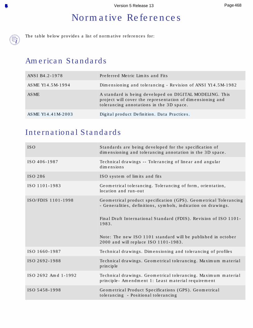
Normative References
The table below provides a list of normative references for:
American Standards ANSI B4.2-1978 Preferred Metric Limits and Fits
ASME Y14.5M-1994 Dimensioning and tolerancing - Revision of ANSI Y14.5M-1982
ASME A standard is being developed on DIGITAL MODELING. This project will cover the representation of dimensioning and tolerancing annotations in the 3D space.
ASME Y14.41M-2003 Digital product Definition. Data Practices.
International Standards
ISO Standards are being developed for the specification of dimensioning and tolerancing annotation in the 3D space.
ISO 406-1987 Technical drawings -- Tolerancing of linear and angular dimensions
ISO 286 ISO system of limits and fits
ISO 1101-1983 Geometrical tolerancing. Tolerancing of form, orientation, location and run-out
ISO/FDIS 1101-1998 Geometrical product specification (GPS). Geometrical Tolerancing - Generalities, definitions, symbols, indication on drawings.
Final Draft International Standard (FDIS). Revision of ISO 1101-1983.
Note: The new ISO 1101 standard will be published in october 2000 and will replace ISO 1101-1983.
ISO 1660-1987 Technical drawings. Dimensioning and tolerancing of profiles
ISO 2692-1988 Technical drawings. Geometrical tolerancing. Maximum material principle
ISO 2692 Amd 1-1992 Technical drawings. Geometrical tolerancing. Maximum material principle- Amendment 1: Least material requirement
ISO 5458-1998 Geometrical Product Specifications (GPS). Geometrical tolerancing - Positional tolerancing
468Page Functional Tolerancing & Annotation Version 5 Release 13
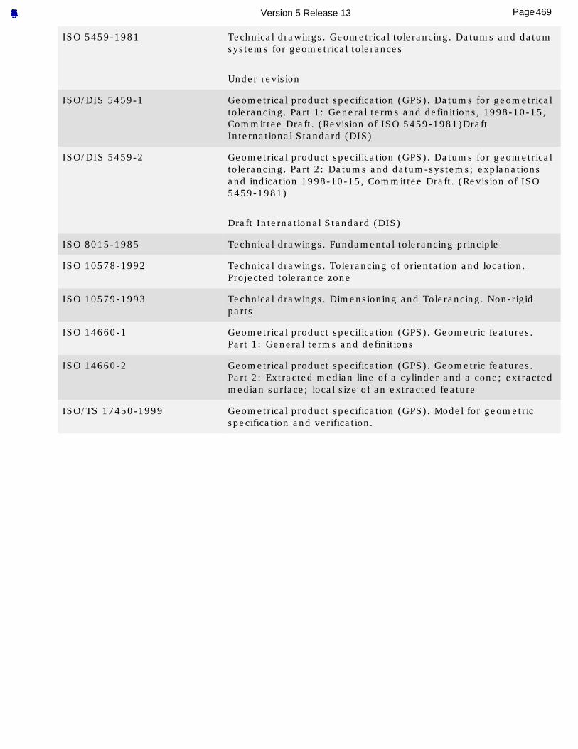
ISO 5459-1981 Technical drawings. Geometrical tolerancing. Datums and datum systems for geometrical tolerances
Under revision
ISO/DIS 5459-1 Geometrical product specification (GPS). Datums for geometrical tolerancing. Part 1: General terms and definitions, 1998-10-15, Committee Draft. (Revision of ISO 5459-1981)Draft International Standard (DIS)
ISO/DIS 5459-2 Geometrical product specification (GPS). Datums for geometrical tolerancing. Part 2: Datums and datum-systems; explanations and indication 1998-10-15, Committee Draft. (Revision of ISO 5459-1981)
Draft International Standard (DIS)
ISO 8015-1985 Technical drawings. Fundamental tolerancing principle
ISO 10578-1992 Technical drawings. Tolerancing of orientation and location. Projected tolerance zone
ISO 10579-1993 Technical drawings. Dimensioning and Tolerancing. Non-rigid parts
ISO 14660-1 Geometrical product specification (GPS). Geometric features. Part 1: General terms and definitions
ISO 14660-2 Geometrical product specification (GPS). Geometric features. Part 2: Extracted median line of a cylinder and a cone; extracted median surface; local size of an extracted feature
ISO/TS 17450-1999 Geometrical product specification (GPS). Model for geometric specification and verification.
469Page Functional Tolerancing & Annotation Version 5 Release 13
Principles and Fundamental Rules for Geometrical Tolerancing
All the dimension, form, orientation and position specifications (either on a geometric feature or on a geometric feature group of a part) are independent (see ISO 8015).
The dimensions of the features and their geometry are independent, regarding the form, the orientation and the position (see ISO 8015).
Each dimension shall have a tolerance, except for the dimensions specially identified as reference, maximum, minimum, or stock (commercial stack size). The tolerance may be applied directly to the dimension (or indirectly in case of basic dimensions), indicated by a general note, or located in a supplementary block of the drawing format, see ANSI Y14.1, ASME Y14.5M-1994).
Dimensioning and tolerancing shall be complete so there is full understanding of the characteristics of each feature. Neither scaling (measuring the size of a feature directly from an engineering drawing) nor assumption of a distance or size is permitted, except as follows: non-dimensioned drawings, such as loft, printed wiring, templates, and master layouts prepared an stable material, are excluded provided the necessary control dimensions are specified, (ASME Y14.5M-1994).
470Page Functional Tolerancing & Annotation Version 5 Release 13
Geometrical Tolerancing
Geometrical Tolerance is the general term applied to the category of tolerances used to control form, profile, orientation, location and runout, (ASME Y14.5M-1994).
True Geometrical Counterpart represents the theoretically perfect boundary (virtual condition or actual mating envelope) or best-fit (tangent) plane of a specified datum feature, (ASME Y14.5M-1994).
The geometrical tolerancing is divided into four types (by both ISO and ASME/ANSI):
● Form tolerances
● Orientation tolerances
● Location or position tolerances
● Runout tolerances
Geometrical tolerance objective is the boundary of spaces in which the toleranced feature has to be located with regards to the specified datum or datum system, to meet the tolerance specification. These particular tolerances allow to limit either actual feature defects or fitted features, with respect to nominal characteristics, and without considering the features' dimensions.
Geometrical tolerancing is based on three feature types:
Tolerance features: a toleranced feature is an actual feature (point, line, surface, except for projected tolerance), or a fitted or a constructed feature. If the toleranced feature corresponds to a group, then each component of the group has the same nature, and the toleranced feature is a toleranced feature group.
Tolerance zone: a tolerance zone is a space (either surface or volume), bounded by one or several nominal features. That space defines the toleranced feature location in order to satisfy the tolerance specification, (see ISO 1101). When the geometrical tolerance applies on a feature group, then one tolerance zone is linked to one feature.
Datum elements or datum systems.
Even if the Geometrical Tolerance creation is accomplished without any semantic links, we recommend you to specify datum elements and then declare your geometrical tolerancing with references.
471Page Functional Tolerancing & Annotation Version 5 Release 13
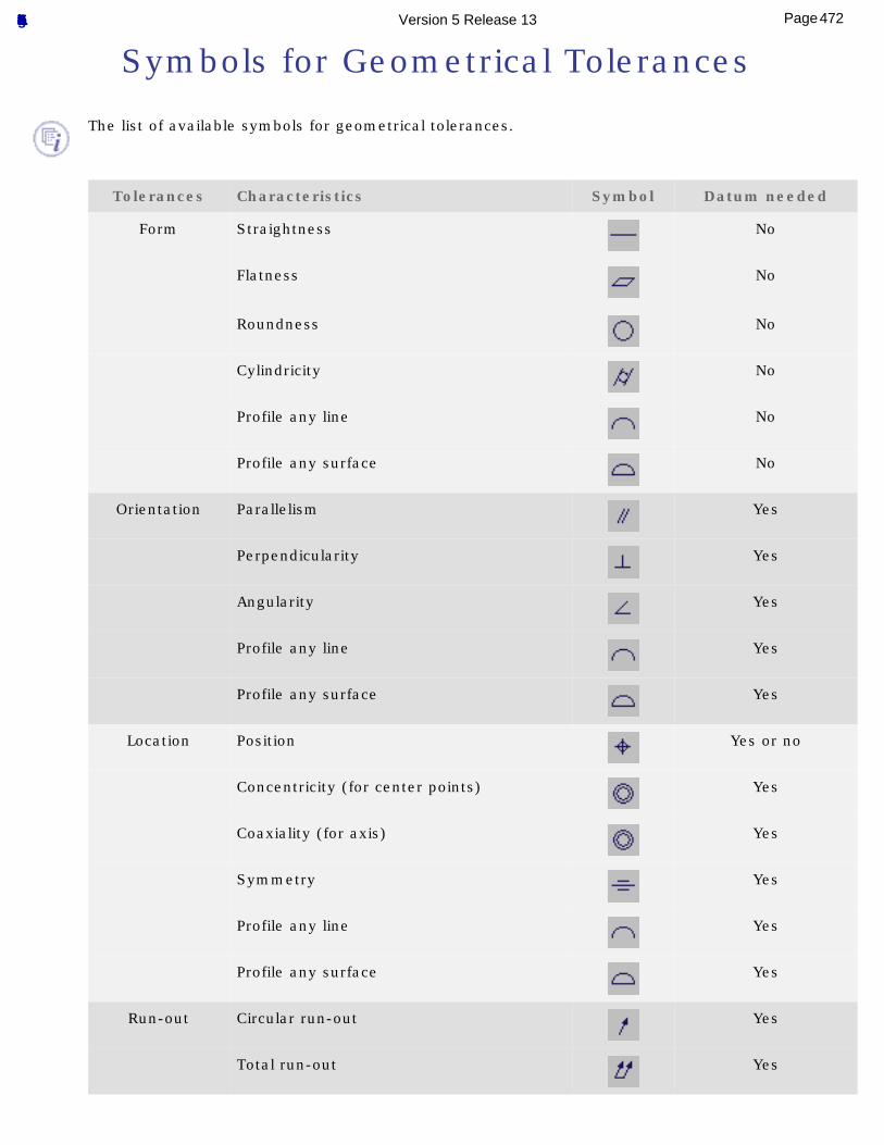
Symbols for Geometrical Tolerances
The list of available symbols for geometrical tolerances.
Tolerances Characteristics Symbol Datum needed
Form Straightness No
Flatness
No
Roundness No
Cylindricity No
Profile any line No
Profile any surface No
Orientation Parallelism Yes
Perpendicularity Yes
Angularity Yes
Profile any line Yes
Profile any surface Yes
Location Position Yes or no
Concentricity (for center points) Yes
Coaxiality (for axis) Yes
Symmetry Yes
Profile any line Yes
Profile any surface Yes
Run-out Circular run-out Yes
Total run-out Yes
472Page Functional Tolerancing & Annotation Version 5 Release 13
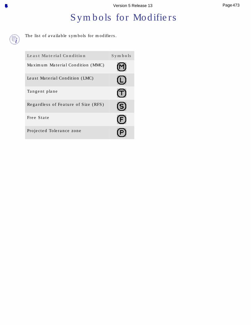
Symbols for Modifiers
The list of available symbols for modifiers.
Least Material Condition Symbols
Maximum Material Condition (MMC)
Least Material Condition (LMC)
Tangent plane
Regardless of Feature of Size (RFS)
Free State
Projected Tolerance zone
473Page Functional Tolerancing & Annotation Version 5 Release 13
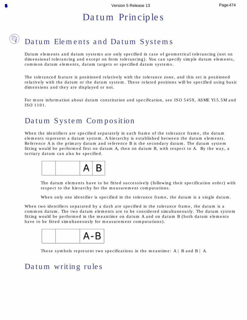
Datum Principles
Datum Elements and Datum SystemsDatum elements and datum systems are only specified in case of geometrical tolerancing (not on dimensional tolerancing and except on form tolerancing). You can specify simple datum elements, common datum elements, datum targets or specified datum systems.
The toleranced feature is positioned relatively with the tolerance zone, and this set is positioned relatively with the datum or the datum system. These related positions will be specified using basic dimensions and they are displayed or not.
For more information about datum constitution and specification, see ISO 5459, ASME Y15.5M and ISO 1101.
Datum System CompositionWhen the identifiers are specified separately in each frame of the tolerance frame, the datum elements represent a datum system. A hierarchy is established between the datum elements. Reference A is the primary datum and reference B is the secondary datum. The datum system fitting would be performed first on datum A, then on datum B, with respect to A. By the way, a tertiary datum can also be specified.
The datum elements have to be fitted successively (following their specification order) with respect to the hierarchy for the measurement computations.
When only one identifier is specified in the tolerance frame, the datum is a single datum.
When two identifiers separated by a dash are specified in the tolerance frame, the datum is a common datum. The two datum elements are to be considered simultaneously. The datum system fitting would be performed in the meantime on datum A and on datum B (both datum elements have to be fitted simultaneously for measurement computations).
These symbols represent two specifications in the meantime: A | B and B | A.
Datum writing rules
474Page Functional Tolerancing & Annotation Version 5 Release 13
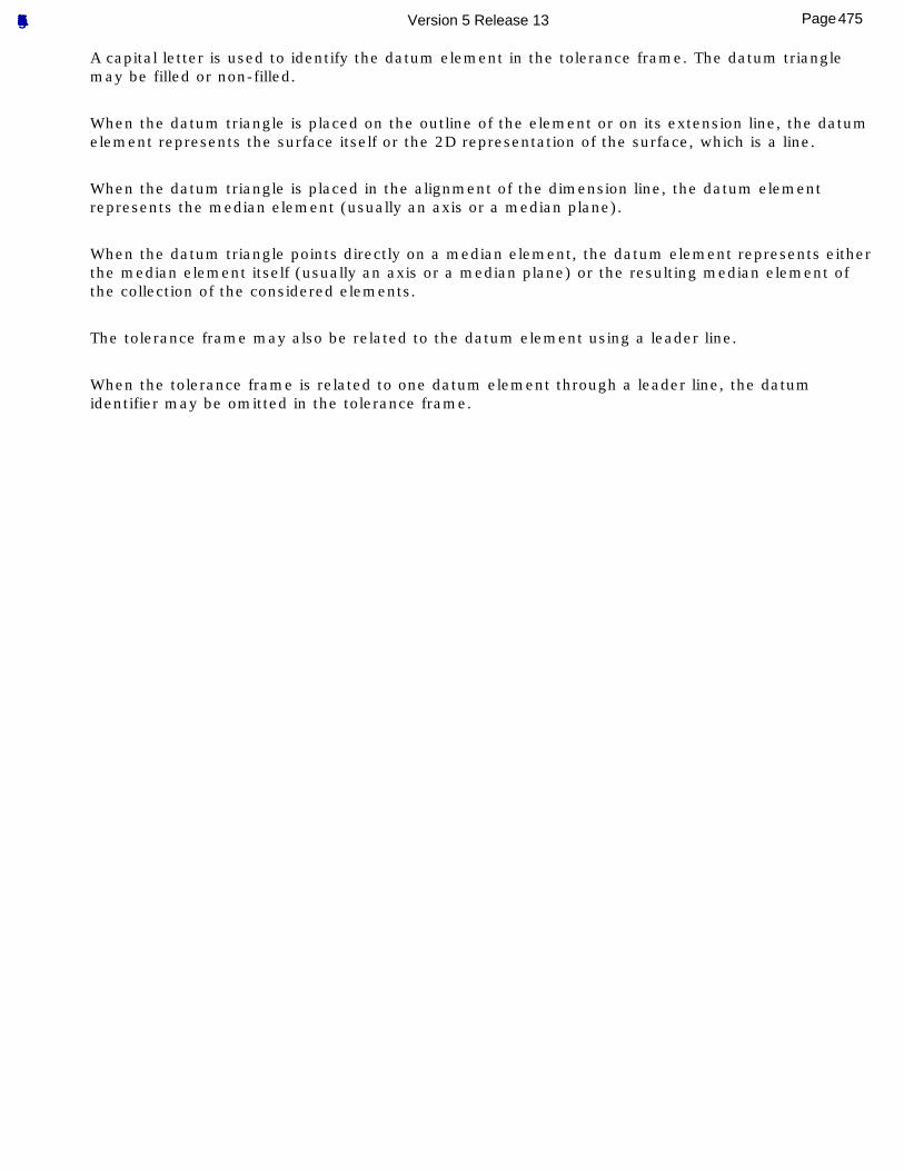
A capital letter is used to identify the datum element in the tolerance frame. The datum triangle may be filled or non-filled.
When the datum triangle is placed on the outline of the element or on its extension line, the datum element represents the surface itself or the 2D representation of the surface, which is a line.
When the datum triangle is placed in the alignment of the dimension line, the datum element represents the median element (usually an axis or a median plane).
When the datum triangle points directly on a median element, the datum element represents either the median element itself (usually an axis or a median plane) or the resulting median element of the collection of the considered elements.
The tolerance frame may also be related to the datum element using a leader line.
When the tolerance frame is related to one datum element through a leader line, the datum identifier may be omitted in the tolerance frame.
475Page Functional Tolerancing & Annotation Version 5 Release 13
Concepts
3D Annotation and Annotation Plane
Non-semantic and Semantic Usage
Note Object Attribute
476Page Functional Tolerancing & Annotation Version 5 Release 13
3D Annotations and Annotation Planes
3D annotations are dimensions, tolerances, notes, text or symbols displayed in 3D according to the same type of 2D annotations defined by standards (ISO, ASME, ANSI, JIS, DIN...).
A 3D annotation is always linked to a user surface or a group of surfaces.
A 3D annotation is displayed in 3D following the orientation of a particular plane called Annotation Plane.Two types of 3D annotation are available: Semantic 3D Annotation and Non-semantic 3D Annotation.
Non-semantic 3D Annotations
3D annotations that are not defined in ISO or ASME/ANSI standards:
● Text
● Flagnote
● Note Object Attribute (NOA)
3D annotations where only their graphical attributes are take into account.There is no control on attribute values.There is no control of consistency regarding the geometry on which it is applied and the other annotations.There is no control of the syntax regarding the standard in use.
● Roughness
● Datum
● Datum target
● Geometrical tolerance
● Dimension
Semantic 3D Annotations
3D annotations on which attribute values, consistency with geometry and syntax are controlled.The annotation validity is warranted along the life cycle application to be re-used and well understood by other applications like tolerance analysis, inspection, manufacturing, assembly process...
477Page Functional Tolerancing & Annotation Version 5 Release 13
● Datum
● Datum target
● Datum reference frame
● Geometrical tolerance
● Dimension
User Surface
Depending the way the parts or products have been designed the surface the user wants to consider can be made of one or several geometrical elements.
Group of Surfaces
A group of surfaces is a set of user surface or group of surfaces. It is used to modelized Tab/Slot, Profile and Pattern features as defined in standards.
Annotation Planes
Annotation planes are the 3D equivalent of 2D views. They contain the 3D annotation or define their orientation.Three types of Annotation planes are available: Projection View, Section View and Section Cut.
● In Projection View Annotation Plane, 3D annotations may be:
❍ Located in planes parallel to this annotation plane and in the background and foreground spaces bounded by this annotation plane.
❍ Related to the geometry finding an intersection with this annotation plane.
❍ Lying on/belonging to this annotation plane.
● In Section View Annotation Plane, 3D annotations may be:❍ Located in planes parallel to this annotation plane and in the background space bounded by
this annotation plane.
❍ Related to the geometry finding an intersection with this annotation plane.
❍ Lying on/belonging to this annotation plane.
● In Section Cut Annotation Plane, 3D annotations may be:❍ Only related to the geometry finding an intersection with this annotation plane.
❍ Only lying on/belonging to this annotation plane.
478Page Functional Tolerancing & Annotation Version 5 Release 13
Non-semantic and Semantic Usage
The goal of the Functional Tolerancing & Annotation product is to fully cover the ISO or ASME/ANSI standards semantic and syntax definitions. Non-semantic 3D annotation can be used in case of Functional Tolerancing & Annotation lacking capabilities or company usage of symbols and syntax that are not covered by standards.
The following Semantic 3D Annotations are available:
● Datum
● Datum target
● Toleranced dimensions applied to Features of Size:❍ Circle
❍ Sphere
❍ Cylinder
❍ Tab/Slot
❍ Angular Tab/Slot
❍ Elongated Hole
❍ Rectangular Holes
● Toleranced dimensions applied to non-Features of Size:❍ Oriented dimension.
479Page Functional Tolerancing & Annotation Version 5 Release 13
Note Object Attribute
PurposeThe Note Object Attribute purpose feature is to provide a way to define user types of 3D annotations and to define their 3D display.
UsageThe recommended usage for such Note Object Attribute feature is the following:
The administrator defines all the company types of Note Object Attribute and stores them in a dedicated catalog:
Finish Data (paint, special processes)
Surface treatment types
Grain Direction
Key Characteristics
Electrical Bonding Location and Specification
Part Marking Location and Specification
Process Data (Specification for processes)
...
The administrator turns off the Note Object Attribute creation setting (see Tolerancing setting) to lock it in order to forbid the creation of new Note Object Attribute types by users.
Users instantiate from the catalog the types of Note Object Attribute they want to specify.
FilteringYou can filter by type of Note Object Attribute the 3D annotations by using the filter command.
480Page Functional Tolerancing & Annotation Version 5 Release 13
Properties
Text Graphical Properties: apply graphical properties to a text.
Text Properties Toolbar: apply graphical properties to a text
Semantic Numerical Display Properties: set semantic numerical display.
481Page Functional Tolerancing & Annotation Version 5 Release 13
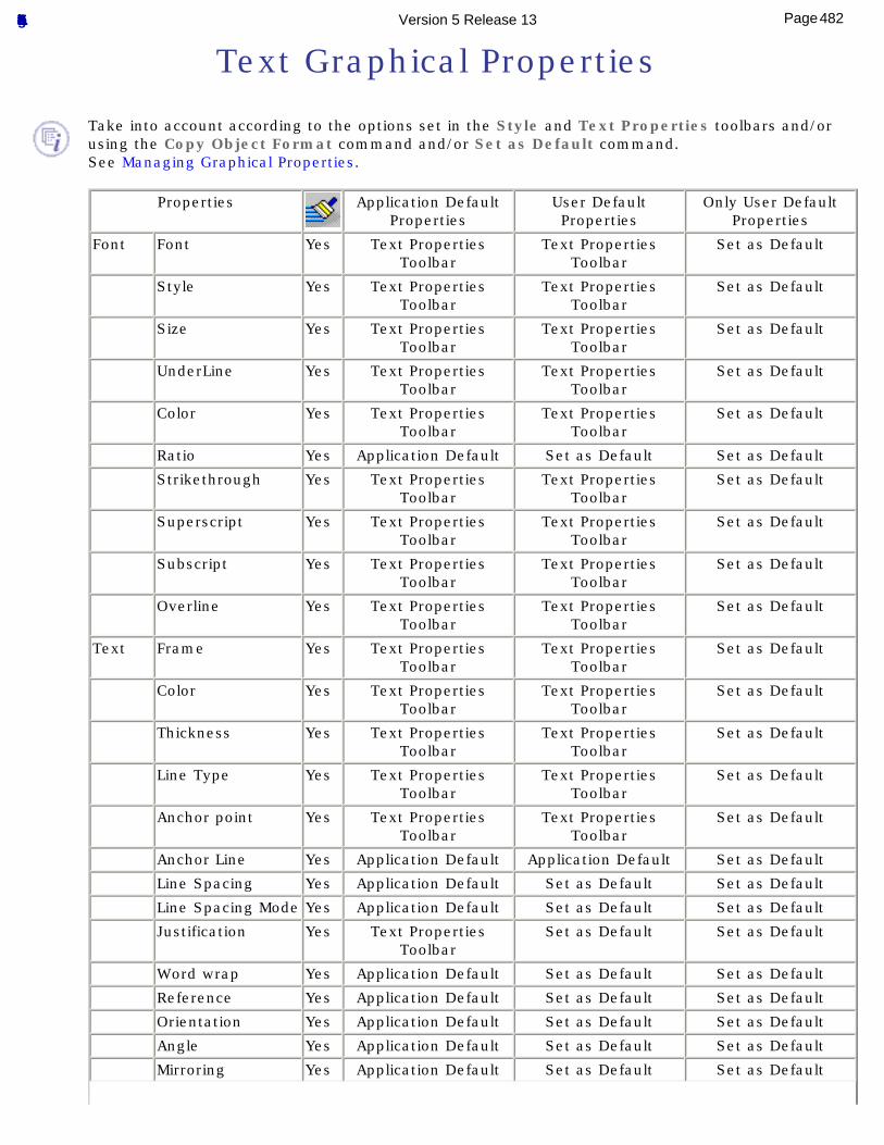
Text Graphical Properties
Take into account according to the options set in the Style and Text Properties toolbars and/or using the Copy Object Format command and/or Set as Default command.See Managing Graphical Properties.
Properties Application Default Properties
User Default Properties
Only User Default Properties
Font Font Yes Text Properties Toolbar
Text Properties Toolbar
Set as Default
Style Yes Text Properties Toolbar
Text Properties Toolbar
Set as Default
Size Yes Text Properties Toolbar
Text Properties Toolbar
Set as Default
UnderLine Yes Text Properties Toolbar
Text Properties Toolbar
Set as Default
Color Yes Text Properties Toolbar
Text Properties Toolbar
Set as Default
Ratio Yes Application Default Set as Default Set as Default
Strikethrough Yes Text Properties Toolbar
Text Properties Toolbar
Set as Default
Superscript Yes Text Properties Toolbar
Text Properties Toolbar
Set as Default
Subscript Yes Text Properties Toolbar
Text Properties Toolbar
Set as Default
Overline Yes Text Properties Toolbar
Text Properties Toolbar
Set as Default
Text Frame Yes Text Properties Toolbar
Text Properties Toolbar
Set as Default
Color Yes Text Properties Toolbar
Text Properties Toolbar
Set as Default
Thickness Yes Text Properties Toolbar
Text Properties Toolbar
Set as Default
Line Type Yes Text Properties Toolbar
Text Properties Toolbar
Set as Default
Anchor point Yes Text Properties Toolbar
Text Properties Toolbar
Set as Default
Anchor Line Yes Application Default Application Default Set as Default
Line Spacing Yes Application Default Set as Default Set as Default
Line Spacing Mode Yes Application Default Set as Default Set as Default
Justification Yes Text Properties Toolbar
Set as Default Set as Default
Word wrap Yes Application Default Set as Default Set as Default
Reference Yes Application Default Set as Default Set as Default
Orientation Yes Application Default Set as Default Set as Default
Angle Yes Application Default Set as Default Set as Default
Mirroring Yes Application Default Set as Default Set as Default
482Page Functional Tolerancing & Annotation Version 5 Release 13
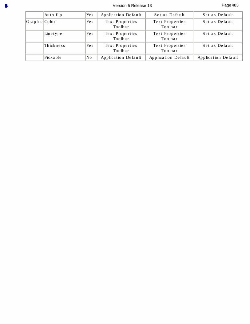
Auto flip Yes Application Default Set as Default Set as Default
Graphic Color Yes Text Properties Toolbar
Text Properties Toolbar
Set as Default
Linetype Yes Text Properties Toolbar
Text Properties Toolbar
Set as Default
Thickness Yes Text Properties Toolbar
Text Properties Toolbar
Set as Default
Pickable No Application Default Application Default Application Default
483Page Functional Tolerancing & Annotation Version 5 Release 13
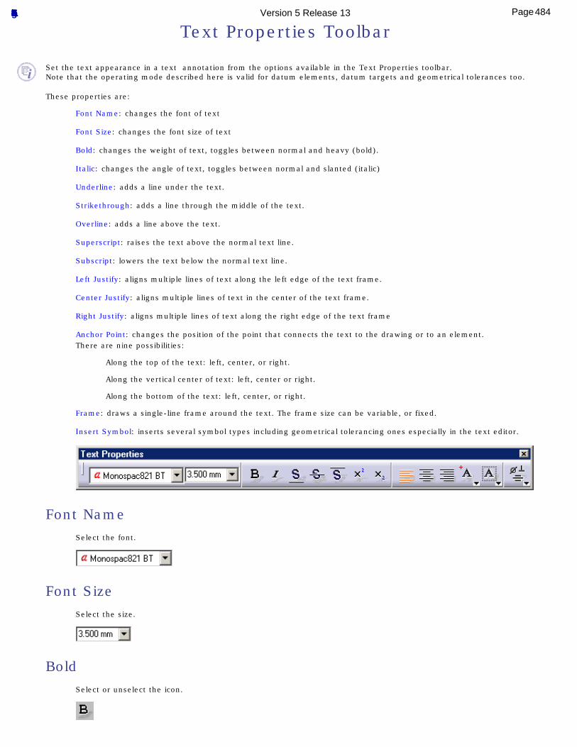
Text Properties Toolbar
Set the text appearance in a text annotation from the options available in the Text Properties toolbar.Note that the operating mode described here is valid for datum elements, datum targets and geometrical tolerances too.
These properties are:
Font Name: changes the font of text
Font Size: changes the font size of text
Bold: changes the weight of text, toggles between normal and heavy (bold).
Italic: changes the angle of text, toggles between normal and slanted (italic)
Underline: adds a line under the text.
Strikethrough: adds a line through the middle of the text.
Overline: adds a line above the text.
Superscript: raises the text above the normal text line.
Subscript: lowers the text below the normal text line.
Left Justify: aligns multiple lines of text along the left edge of the text frame.
Center Justify: aligns multiple lines of text in the center of the text frame.
Right Justify: aligns multiple lines of text along the right edge of the text frame
Anchor Point: changes the position of the point that connects the text to the drawing or to an element.There are nine possibilities:
Along the top of the text: left, center, or right.
Along the vertical center of text: left, center or right.
Along the bottom of the text: left, center, or right.
Frame: draws a single-line frame around the text. The frame size can be variable, or fixed.
Insert Symbol: inserts several symbol types including geometrical tolerancing ones especially in the text editor.
Font NameSelect the font.
Font SizeSelect the size.
BoldSelect or unselect the icon.
484Page Functional Tolerancing & Annotation Version 5 Release 13
ItalicSelect or unselect the icon.
UnderlineSelect the icon.
StrikethroughSelect the icon.
OverlineSelect the icon.
SuperscriptSelect the icon.
SubscriptSelect the icon.
Left JustifySelect the icon.
Center JustifySelect the icon.
Right JustifySelect the icon.
485Page Functional Tolerancing & Annotation Version 5 Release 13
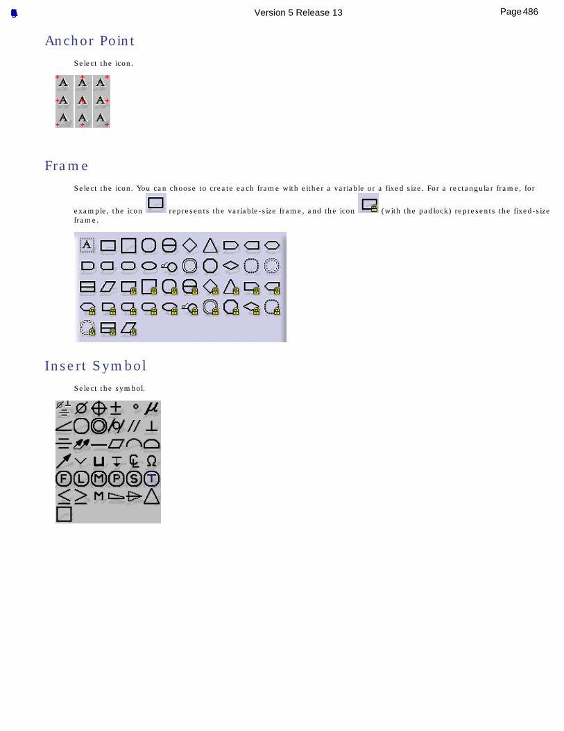
Anchor PointSelect the icon.
FrameSelect the icon. You can choose to create each frame with either a variable or a fixed size. For a rectangular frame, for
example, the icon represents the variable-size frame, and the icon (with the padlock) represents the fixed-size frame.
Insert SymbolSelect the symbol.
486Page Functional Tolerancing & Annotation Version 5 Release 13
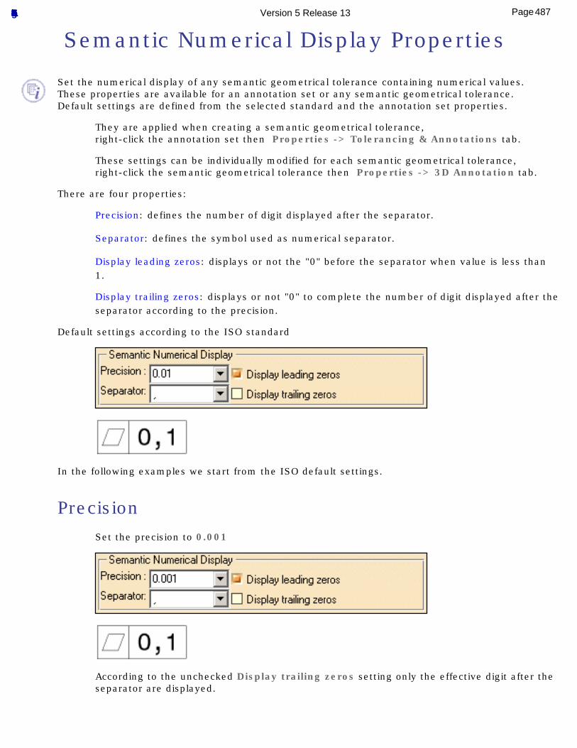
Semantic Numerical Display Properties
Set the numerical display of any semantic geometrical tolerance containing numerical values.These properties are available for an annotation set or any semantic geometrical tolerance.Default settings are defined from the selected standard and the annotation set properties.
They are applied when creating a semantic geometrical tolerance,right-click the annotation set then Properties -> Tolerancing & Annotations tab.
These settings can be individually modified for each semantic geometrical tolerance,right-click the semantic geometrical tolerance then Properties -> 3D Annotation tab.
There are four properties:
Precision: defines the number of digit displayed after the separator.
Separator: defines the symbol used as numerical separator.
Display leading zeros: displays or not the "0" before the separator when value is less than 1.
Display trailing zeros: displays or not "0" to complete the number of digit displayed after the separator according to the precision.
Default settings according to the ISO standard
In the following examples we start from the ISO default settings.
PrecisionSet the precision to 0.001
According to the unchecked Display trailing zeros setting only the effective digit after the separator are displayed.
487Page Functional Tolerancing & Annotation Version 5 Release 13
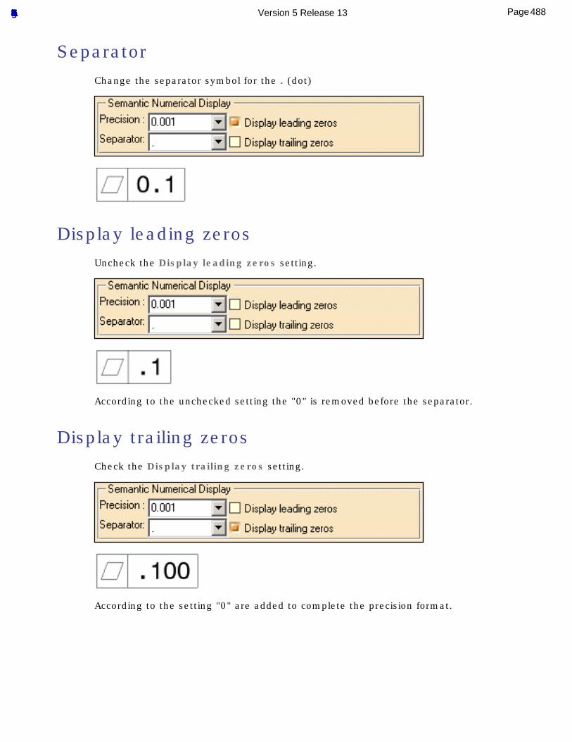
SeparatorChange the separator symbol for the . (dot)
Display leading zerosUncheck the Display leading zeros setting.
According to the unchecked setting the "0" is removed before the separator.
Display trailing zerosCheck the Display trailing zeros setting.
According to the setting "0" are added to complete the precision format.
488Page Functional Tolerancing & Annotation Version 5 Release 13
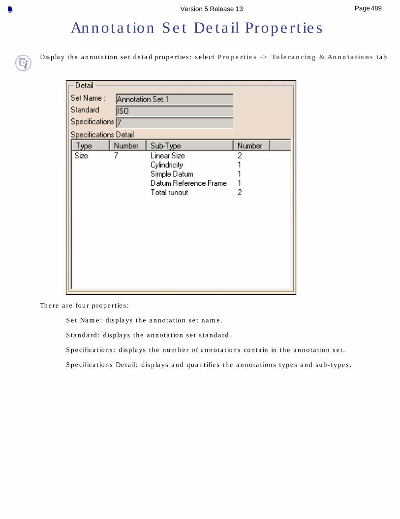
Annotation Set Detail Properties
Display the annotation set detail properties: select Properties -> Tolerancing & Annotations tab
There are four properties:
Set Name: displays the annotation set name.
Standard: displays the annotation set standard.
Specifications: displays the number of annotations contain in the annotation set.
Specifications Detail: displays and quantifies the annotations types and sub-types.
489Page Functional Tolerancing & Annotation Version 5 Release 13
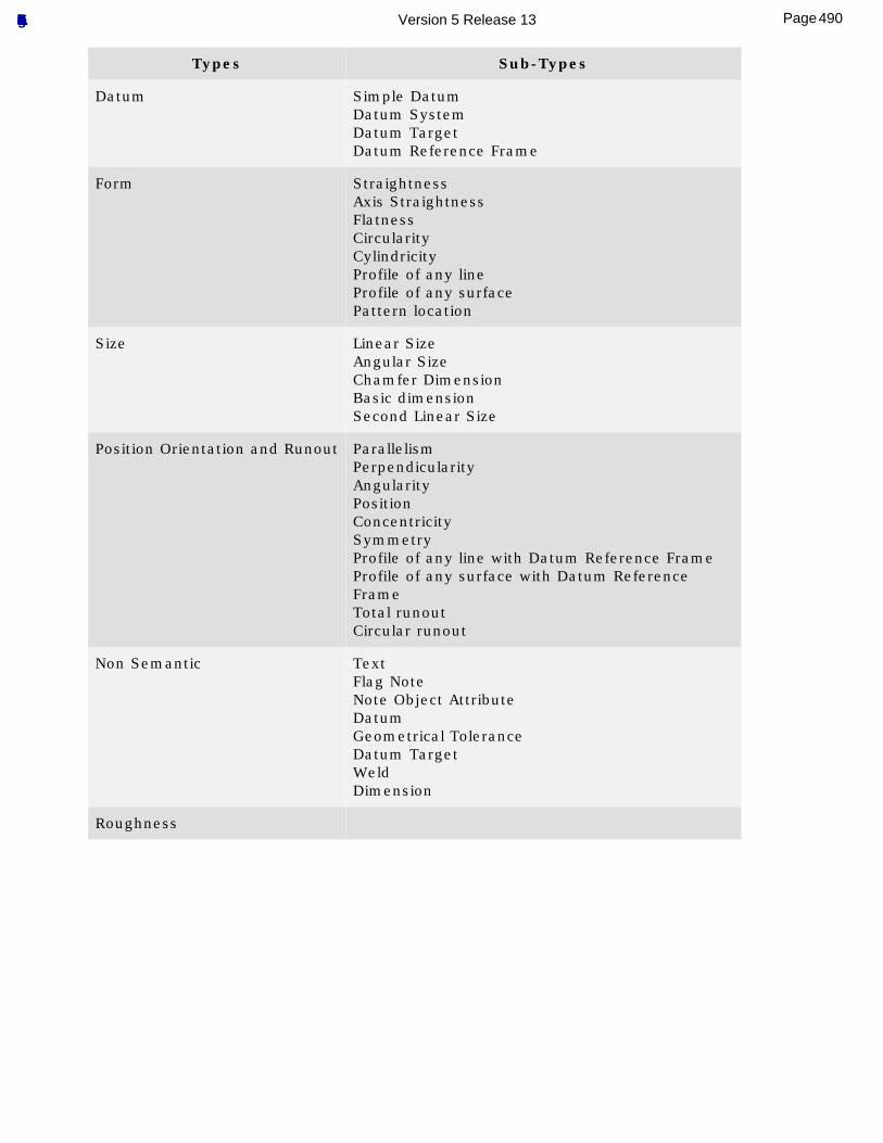
Types Sub-Types
Datum Simple DatumDatum SystemDatum TargetDatum Reference Frame
Form StraightnessAxis StraightnessFlatnessCircularityCylindricityProfile of any lineProfile of any surfacePattern location
Size Linear SizeAngular SizeChamfer DimensionBasic dimensionSecond Linear Size
Position Orientation and Runout ParallelismPerpendicularityAngularityPositionConcentricitySymmetryProfile of any line with Datum Reference FrameProfile of any surface with Datum Reference FrameTotal runoutCircular runout
Non Semantic TextFlag NoteNote Object AttributeDatumGeometrical ToleranceDatum TargetWeldDimension
Roughness
490Page Functional Tolerancing & Annotation Version 5 Release 13
Dimension Units
Default Dimension Unit When Creating an Annotation Set
The default dimension unit is defined by the standard default numerical formats for length and angle, see Tolerancing option for standard selection:
1. Select Tools -> Standards...
2. In the Standards Definition dialog box, select Drafting category and the
Standard_Name.xml file according to the selected standard.
3. Select Standard -> Standard_Name -> General -> DefaultNumericalFormatLength
to see the default length format for the selected standard
and/or
select Standard -> Standard_Name -> General -> DefaultNumericalFormatAngle to
see the default angle format for the selected standard.
If no standard has been defined, the dimension unit is set by the Length unit in theTools -> Options -> General -> Parameters and Measure, Units tab.
Modifying the Default Dimensions Unit To modify default dimensions unit you can:
● Set the Numerical Display Description combo unit in the Dimension Properties Toolbar.
● Set the Length (or Angle) unit in the Tools -> Options -> General -> Parameters and Measure, Units tab, in this case the Numerical Display Description combo is updated according to the Length (or Angle) unit.
491Page Functional Tolerancing & Annotation Version 5 Release 13
Statistic Laws
Statistic laws are used to characterize deviation annotations. interpret annotation tolerance in a deviation annotation. These deviation annotations can be directly specified by the user or generated from a annotation's tolerance translation.
For a statistical analysis, an annotation tolerance is interpreted as random variable or variate.
For a determinist analysis, the mean of the annotation tolerance is used as determinist value.
Normal Law: describe the Normal probability law equations.
Uniform Law: describe the Uniform probability law equations.
Constant Law: describe the Constant probability law equations.
Pearson Law: describe the Pearson probability law equations.
Poisson Law: describe the Poisson probability law equations.
Snedecor Law: describe the Snedecor probability law equations.
492Page Functional Tolerancing & Annotation Version 5 Release 13
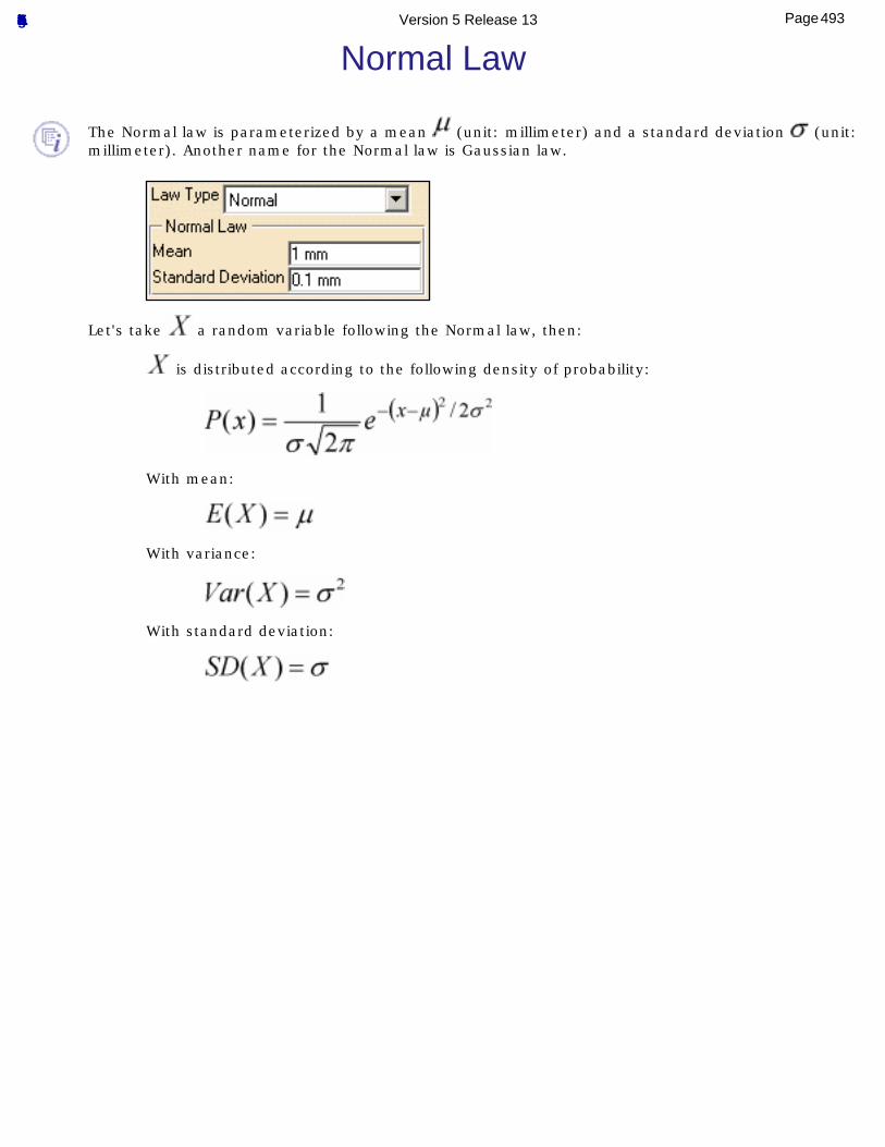
Normal Law
The Normal law is parameterized by a mean (unit: millimeter) and a standard deviation (unit: millimeter). Another name for the Normal law is Gaussian law.
Let's take a random variable following the Normal law, then:
is distributed according to the following density of probability:
With mean:
With variance:
With standard deviation:
493Page Functional Tolerancing & Annotation Version 5 Release 13
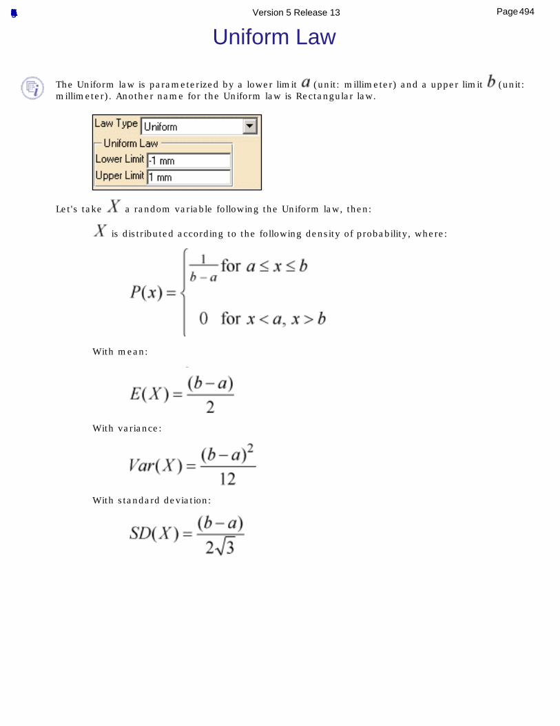
Uniform Law
The Uniform law is parameterized by a lower limit (unit: millimeter) and a upper limit (unit: millimeter). Another name for the Uniform law is Rectangular law.
Let's take a random variable following the Uniform law, then:
is distributed according to the following density of probability, where:
With mean:
With variance:
With standard deviation:
494Page Functional Tolerancing & Annotation Version 5 Release 13
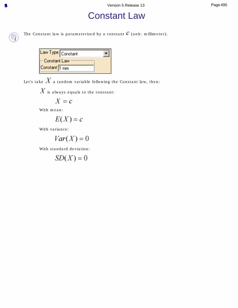
Constant Law
The Constant law is parameterized by a constant (unit: millimeter).
Let's take a random variable following the Constant law, then:
is always equals to the constant:
With mean:
With variance:
With standard deviation:
495Page Functional Tolerancing & Annotation Version 5 Release 13

Pearson Law
The Pearson law is parameterized by (no unit). Another name for the Pearson law is Chi-squared law.If random variables follows the Normal law with mean 0 and variance 1, then:
Let's take a random variable following the Pearson law, then:
is distributed according to the following density of probability, where:
And where is a Gamma function.
With mean:
With variance:
With standard deviation:
496Page Functional Tolerancing & Annotation Version 5 Release 13
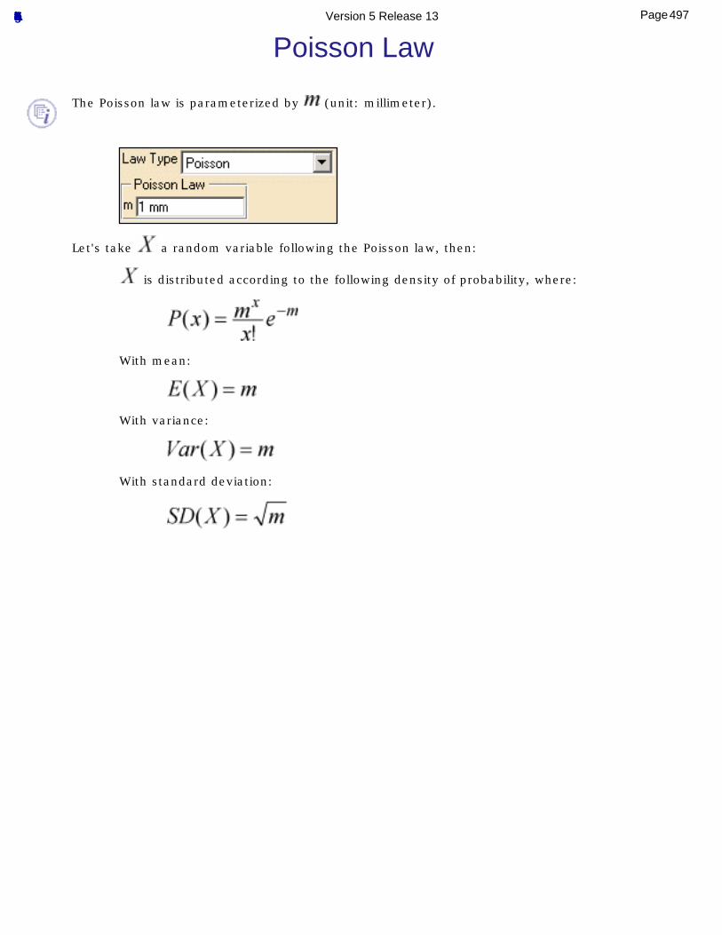
Poisson Law
The Poisson law is parameterized by (unit: millimeter).
Let's take a random variable following the Poisson law, then:
is distributed according to the following density of probability, where:
With mean:
With variance:
With standard deviation:
497Page Functional Tolerancing & Annotation Version 5 Release 13
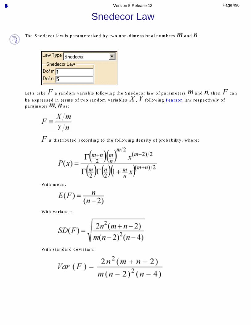
Snedecor Law
The Snedecor law is parameterized by two non-dimensional numbers and .
Let's take a random variable following the Snedecor law of parameters and , then can
be expressed in terms of two random variables , following Pearson law respectively of parameter , as:
is distributed according to the following density of probability, where:
With mean:
With variance:
With standard deviation:
498Page Functional Tolerancing & Annotation Version 5 Release 13
Glossary
A
Associated Derived Feature Center point, axis or median plane derived from one or more associated integral features (ISO 14660).
Associated Integral Feature Feature of perfect form associated to the extracted integral feature in accordance with specified conventions (ISO 14660).
C
Common Datum Datum based on two or more surfaces considered simultaneously (ISO/CD 5459-1:1998).
D
Datum
A theoretically exact point, axis, or plane derived from the true geometric counterpart of a specified datum feature. A datum is the origin from which the location or geometric characteristics of features of a part are established, (ASME Y14.5M-1994).
Situation feature used to define the position and/or orientation of a tolerance zone or to define the position and/or the orientation of the virtual conditions (in the case of the complementary requirements, e.g maximum material requirement), (ISO/CD 5459-1:1998(E)).
Datum System Ordered list of at least two datums and at most three datums, which may be single or common datums, (ISO/CD 5459-1:1998(E)).
Note: A datum-system is used to define the position and/or orientation of a tolerance zone or to define the position and/or the orientation of the virtual condition (in the case of complementary requirements, e.g maximum material requirement).
499Page Functional Tolerancing & Annotation Version 5 Release 13
(Datum) Target A specified point, line, or area on a part used to establish a datum, (ASME Y14.5M-1994).
Portion of an integral feature (surface) which can be a point, a line or an area and which is used for establishing a datum, (ISO/CD 5459-1:1998(E)).
Datum Feature An actual feature of a part that is used to establish a datum, (ASME Y14.5M-1994).
Derived Feature Center point, median line or median surface from one or more integral features (ISO 14660)
Examples:
1- The center of a sphere is derived feature obtained from the sphere, which is an integral feature.
2 -The median line of a cylinder is a derived feature obtained from the cylindrical surface, which is an integral feature.
E
Extracted Derived Feature Center point, median line or median surface derived from one or more extracted integral features (ISO 14660).
Note: For convenience:
- the derived median line of an extracted cylindrical surface is called an extracted median line (see ISO 14660-2).
- the derived median surface of 2 opposite extracted planar surfaces is called an extracted median surface (see ISO 14660-2).
Extracted Integral Feature Approximated representation of the real (integral) feature, obtained by extracting a finite number of points from the real (integral) feature performed in accordance with specified conventions. (ISO 14660)
Note: This representation is defined according to the required function of the feature. Several such representations may exist for each real (integral) feature.
F
500Page Functional Tolerancing & Annotation Version 5 Release 13
Feature The general term applied to a physical portion of a part, such as a surface, pin, tab, hole or slot, (ASME Y14.5M-1994).
Geometric feature, point, line or surface, (ISO 14660-1).
Feature of Size Geometric shape defined by a linear or angular dimension which is a size(ISO 14660)
Notes
1- The features of size can be a cylinder, a sphere, two parallel opposite surfaces, a cone or a wedge.
2- In standards such as ISO 286-1 and ISO/R 1938 the terms plain workpiece and single features are used with a meaning close to "feature size".
G
Geometric Feature Point, line or surface (ISO 14660).
I
Integral Feature Surface or line on a surface (ISO 14660)
Note: An integral feature is intrinsically defined.
N
Nominal integral feature Theoretically exact integral feature as defined by a technical drawing or by other means (ISO 14660).
Nominal Derived Feature Center point, axis or median plane derived from one or more nominal integral features (ISO 14660)
Note: On the technical drawing nominal derived features are mostly represented by chain lines (dash-dotted lines).
501Page Functional Tolerancing & Annotation Version 5 Release 13
R
Real (integral) Feature Integral feature part of a real surface of a workpiece limited by the adjacent real (integral) features (ISO 14660).
Note: No real derived feature exist.
Real Surface of a Workpiece Set of features which physically exist and separate the entire workpiece from the surrounding medium (ISO 14660).
Restricted Surface Portion of an integral feature (surface) which is an area and which is used for establishing a datum (ISO/CD 5459-1:1998)
Note: the area of a restricted surface is relatively large compared with the complete surface.
S
Single Datum Datum based on one surface considered alone (ISO/CD 5459-1:1998).
Situation Feature Ideal feature which is a point, a straight line, a plane or a helix, from which the position and/or the orientation of a feature can be defined (ISO/CD 5459-1:1998)
Note: Situation features are defined by and are characteristics of the class of surface involved.
Surface class Group of surfaces having the same degree of freedom for which the surfaces are unvarying, (ISO/CDIS 5459-1:1998(E)).
T
Tolerance zone Space limited by one or several geometrically perfect lines or surfaces, and characterized by a linear dimension, called a tolerance
(ISO/FDIS 1101:2000(E))
502Page Functional Tolerancing & Annotation Version 5 Release 13
Index
Numerics3D Annotations
non-semantic
semantic
3D Grid
AAmerican Standards Annotation
correlated deviation
deviation
distance between two points annotation
disabling
enabling
filter
group and order
group automatically
group during creation
group manually
isolated
querying
specifying
transferring during creation
transferring existing Annotation Links
Create Orientation Link
Create Positional Link
503Page Functional Tolerancing & Annotation Version 5 Release 13
Delete Orientation Link
Delete Positional Link
Query Object Links
ASME
ASME Y14.41M-2003
ASME Y14.5M-1994
Bbasic dimensions
blue reference axis breakpoint
add an extremity
create
Ccapture
Capture Management
create
display
manage command
3D Annotation Query Switch On/Switch Off
Activate View
Active View State
Add Component
Add Family
Add Leader
Aligned Section View/Section Cut
Anchor Point
Automatic Grouping
504Page Functional Tolerancing & Annotation Version 5 Release 13
Basic Dimension
Bold
Capture
Capture Management
Center Justify
Check Validity
Clipping Plane
Constructed Geometry Creation
Constructed Geometry Management
Coordinate Dimensions
Copy Object Format
Correlated Deviation
Correlated Deviations
Create Constructed Geometry
Create/Define hyperlinks
Cumulated Dimensions
Current State
Curvilinear Dimensions
Custom Report
Datum
Datum Feature
Datum Target
Default Annotation
Deviation
Deviations
Dimension Line
Dimensions
Disabling 3D Annotations
Display 3D Grid
Display Capture
Display Grid
Distance Between Two Points
505Page Functional Tolerancing & Annotation Version 5 Release 13
Enable/Disable Tolerancing Sets by List
Exit from Capture
Filter
Flag Note
Flag Note with Leader
Font Name
Font Size
Frame
Free rotation
Front View
Generative Dimension
Geometrical Tolerance
Geometry Canonicity Re-specification
Geometry Connection Management
Horizontal Position
Insert Symbol
Instantiate From Document
Invert Normal
Italic
Left Justify
Manage associativity
Manage Constructed Geometry
Managing Associativity Between Elements
Manual Grouping
Mirror Annotations
Named views
Normal View
Note Object Attribute
Numerical Display Description
Offset Section View/Section Cut
Orientation
Overline
506Page Functional Tolerancing & Annotation Version 5 Release 13
Partial Surface
Position along Normal Axis
PowerCopy Creation
Powercopy Creation
Precision
Projection View
Properties
Report
Right Justify
Roughness
Save In Catalog
Save in Catalog
Section Cut
Section Cut (Annotation Plane)
Section Cut View
Section View
Section View (Annotation Plane)
Select Annotations
Select Camera
Select Views/Annotation Plane
Set Current
Snap to Point
Stacked Dimensions
Standards...
Strikethrough
Style
Subscript
Superscript
Text
Text Parallel to Screen
Text with Leader
Thread Representation Creation
507Page Functional Tolerancing & Annotation Version 5 Release 13
Tolerance
Tolerance Description
Tolerancing Advisor
Underline
Unset Current
Vertical Position
common datum Constructed geometry
automatic creation
create
manage
manual creation contextual command
Add a Breakpoint
Add an Extremity
Add an Interruption
Add Tolerance
All Around
Annotation Links
Attribute Link
Create Orientation Link
Create Positional Link
Delete Orientation Link
Delete Positional Link
Edit Generative Parameter
Query Object Links
Remove Interruptions
Replace Datum Reference Frame
Set as Default
Switch to orientation free leader
Switch to perpendicular leader
Symbol Shape
Transfer to View/Annotation Plane
508Page Functional Tolerancing & Annotation Version 5 Release 13
coordinate dimensions
cumulated dimensions
curvilinear dimensions
Ddatum
creating datum reference frame
creating
datum system
datum target
datum triangle
default tolerance
dimensions
basic
coordinate
cumulated
curvilinear
stacked
dot
Eextraction views
aligned section view/section cut
offset section view/section cut
Ffiltering annotations
509Page Functional Tolerancing & Annotation Version 5 Release 13
GGeometrical Tolerance
geometrical tolerances Geometry Connection Management
add component
add geometry
check validity
delete
geometry highlight
reconnect
rename
scope range
green reference axis
Iidentifier
International Standards introducing
Tolerancing Advisor
ISO
ISO 10578-1992
ISO 10579-1993
ISO 1101-1983
ISO 14660-1
ISO 14660-2
ISO 1660-1987
ISO 2692 Amd 1-1992
ISO 2692-1988
ISO 5458-1998
510Page Functional Tolerancing & Annotation Version 5 Release 13
ISO 5459 -1981
ISO/8015-1985
ISO/DIS 5459-1
ISO/DIS 5459-2
ISO/FDIS 1101-1998
ISO/TS 17450-1999
isolated annotations
Lleader
creating
Mmanage
capture
managing view/annotation plane associativity
manipulator
migrating V4 FDT data
modifiers
NNon-semantic 3D Annotations
normative references Note Object Attribute
concept
editing
filtering
From ditto (2D component)
511Page Functional Tolerancing & Annotation Version 5 Release 13
From text
hyperlinks
instantiate
Store into a catalog
usage
Ooption
Geometry Highlight
Parallel to Screen
Scope Range
PPower copy
creating
instantiating
saving into catalog properties
advanced text
Annotation Set Detail
basic text
copy
group
Semantic Numerical Display
Set as Default
setting
Text Graphical
Text Properties toolbar
512Page Functional Tolerancing & Annotation Version 5 Release 13
Qquerying 3D annotations
Rrotate
SSemantic 3D Annotations
semantic link
stacked dimensions standard
ASME
ASME Y14.41M-2003
ASME Y14.5M-1994
choosing
ISO
ISO 10578-1992
ISO 10579-1993
ISO 1101-1983
ISO 14660-1
ISO 14660-2
ISO 1660-1987
ISO 2692 Amd 1-1992
ISO 2692-1988
ISO 5458-1998
ISO 5459-1981
ISO/8015-1985
ISO/DIS 5459-1
ISO/DIS 5459-2
513Page Functional Tolerancing & Annotation Version 5 Release 13
ISO/FDIS 1101-1998
ISO/TS 17450-1999 Statistic Law
Constant
Normal
Pearson
Poisson
Snedecor
Uniform sub-toolbar
Constructed Geometry
Deviations (Extended)
Dimensions
Flag Notes
Reports
Texts
Views
symbols
Ttext
associative
creating thread dimensioning and tolerancing
Tolerancing Advisor
tolerancing Tolerancing Advisor
Diameter (One surface)
Distance Creation (Tab/Slot)
introducing
Position with DRF Specification (Elongated Pin/Hole)
Position with DRF Specification (Non cylindrical Pin/Hole)
514Page Functional Tolerancing & Annotation Version 5 Release 13
Profile of a Surface
Semantic Datum (N surfaces)
Semantic Datum (One surface)
Semantic Datum (Tab/Slot)
Text with Leader (One surface)
thread dimensioning and tolerancing toolbar
3D Grid
Annotations
Camera
Capture
Capture Options
Capture Visualization
Deviations (Compact)
Dimension Properties Toolbar
Geometry for 3D Annotations
Grouping
Note Object Attribute
Position and Orientation
Reporting
Style
Text Properties
Views/Annotation Planes
Visualization
Workbench Tools Options
3D Annotation Query
3D Functional Tolerancing and Annotation
Angular Size
Annotation Creation
Annotation Parameters
Annotation tab
Annotations in Specification Tree
515Page Functional Tolerancing & Annotation Version 5 Release 13
Automatic Creation
Constructed Geometry tab
Dimension Creation
Dimension Manipulators
Dimension related to an origin
Dimension tab
Display tab
Geometrical Tolerance
Graphic Properties
Grid
Leader associativity to the geometry
Limits
Linear Size
Line-Up
Manipulators
Manipulators tab
Move
Non-Semantic
Note Object Attribute
Partial Surface
Rotation
Semantic Control
Surface Normal
Tolerances tab
Tolerancing Standard
Tolerancing tab
View/Annotation Plane Associativity
View/Annotation Plane Display
View/Annotation Plane tab
516Page Functional Tolerancing & Annotation Version 5 Release 13
VV4 data, migrating view/annotation plan
normal axis view/annotation plane
activating
aligned section view/section cut
associativity
blue reference axis
green reference axis
offset section view/section cut
projection
properties
section
section cut
using
yellow reference axis
Yyellow reference axis
517Page Functional Tolerancing & Annotation Version 5 Release 13