Embed Size (px)
Citation preview

Pad Drilling Using Magnetic MWD
Managing Magnetic Interference from nearby casing
Neil Bergstrom, P.E. Wellbore Geodetic Specialist – Devon EnergyISCWSA SPE W llb P iti i T h S tiISCWSA – SPE Wellbore Positioning Tech SectionDenver 3 November 2011
MWD Surveying in Top-Hole Section
• Common practice is to use gyro surveys (gyroMWD or single shot i li ) h l b l iwireline) when close to nearby steel casing.
• Distance varies with operator and/or contractor. Typically gyros are specified to 20-50 feet, or when MWD fails QC limits.
• Magnetic interference from nearby wells changes the apparent azimuth measured by magnetic tools.
• The interference cannot be measured with a single survey shot but b d l h d ff d hit can be estimated using several survey shots at different depths.
• The azimuth error can be estimated.• The effect is to make the Ellipse of Uncertainty (EoU) larger.p y ( ) g• Magnetic Interference does not effect the measured inclination. • In near-vertical wells azimuth errors have small effect on position.
NYSE: DVN www.devonenergy.com page 2

How External Magnetic interference changes Azimuth g
• Only the horizontal part of the measured field is used to determine h i h b h l Z i d i h the azimuth between the tool Z-axis and apparent magnetic north.
• External interference changes the direction to apparent magnetic north.
• Only the EW component of interference changes this angle.– THIS CANNOT BE MEASURED WITH A STANDARD MWD TOOL
• Only the NS component changes the magnitude of BH. Only the NS component changes the magnitude of BH. • The Azimuth change is ATan(EWinterference/BHref)• Interference < BH will change the measured azimuth by <45
degrees degrees. • Interference > BH can potentially swing azimuth by 180 degrees. • At low inclination the change in wellbore position is minimal.
– At 1 degree inc a 1 degree azi error => 0.3 ft BHL change/1000 ft.
NYSE: DVN www.devonenergy.com page 3

How External Magnetic Interference changes Azimuthg
• This shows how magnetic interference swings the apparent declination. The angle of change is ATan (BInterference/BNorth)
BInterferenceEW
BNorth
45˚
NYSE: DVN www.devonenergy.com page 4

Considerations using Magnetic MWD near existing steel casingg g
• The inclination measurement is OK.• The azimuth has reduced accuracy. It takes a very large amount of
interference (~BH) to change the azimuth more than 45 degrees. • In near vertical wells typical of top hole drilling, small errors in yp p g,
azimuth do not make much change in bottom hole position. • Additional interference can be tolerated if the IPM used to plan the
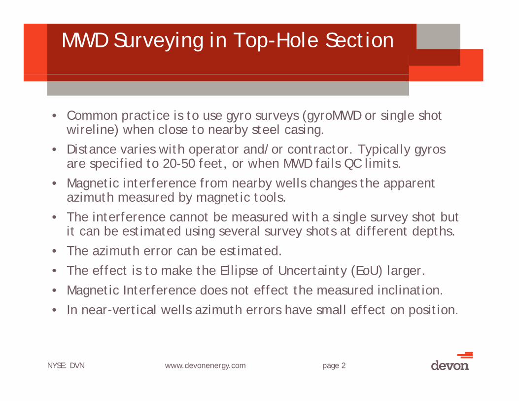
ellipse size is designed for this. • Typical MWD ellipse size at 1000 ft in a low angle (<5 degrees) well
is ~+/- 3 feet• Typical ellipse size with 2000 nT interference is ~+/- 6 feet (2X)yp p ( )• With careful planning these larger ellipses can be accommodated.
NYSE: DVN www.devonenergy.com page 5
Examples of Ellipse Size Changes(Landmark Compass)( p )
Standard MWD IPMDepth Slice at 1000 Ft.
MWD+Magnetic Interference (2000 nT or 7.5 degrees)
NYSE: DVN www.devonenergy.com page 6
Multi-Well Pad Project Planning
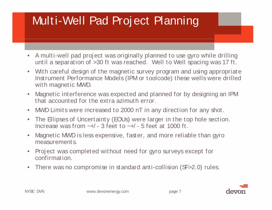
• A multi-well pad project was originally planned to use gyro while drilling until a separation of >30 ft was reached. Well to Well spacing was 17 ft.p p g
• With careful design of the magnetic survey program and using appropriate Instrument Performance Models (IPM or toolcode) these wells were drilled with magnetic MWD.M i i f d d l d f b d i i IPM • Magnetic interference was expected and planned for by designing an IPM that accounted for the extra azimuth error.
• MWD Limits were increased to 2000 nT in any direction for any shot. The Ellipses of Uncertainty (EOUs) were larger in the top hole section • The Ellipses of Uncertainty (EOUs) were larger in the top hole section. Increase was from ~+/- 3 feet to ~+/- 5 feet at 1000 ft.
• Magnetic MWD is less expensive, faster, and more reliable than gyro measurements.
• Project was completed without need for gyro surveys except for confirmation.
• There was no compromise in standard anti-collision (SF>2.0) rules.
NYSE: DVN www.devonenergy.com page 7
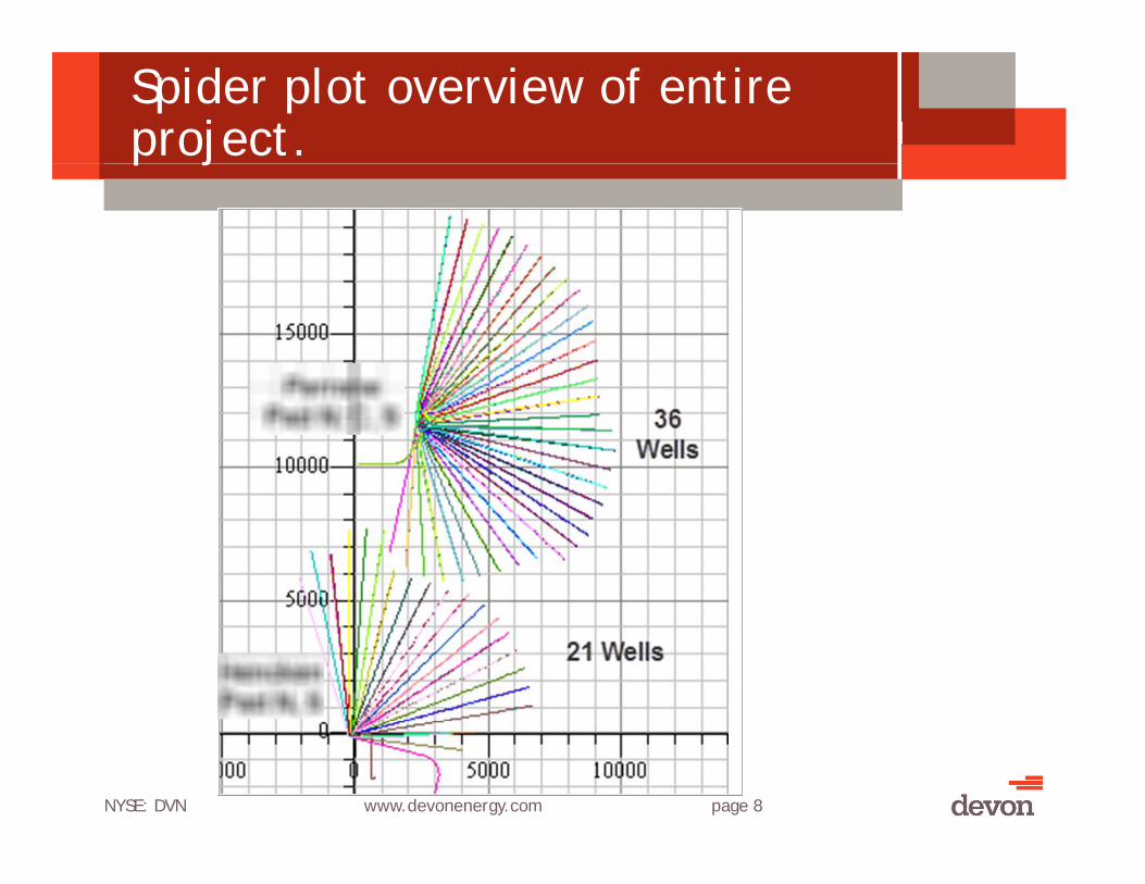
Spider plot overview of entire project. p j
NYSE: DVN www.devonenergy.com page 8
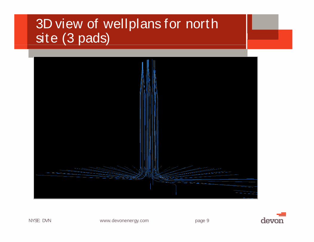
3D view of wellplans for north site (3 pads)( p )
NYSE: DVN www.devonenergy.com page 9
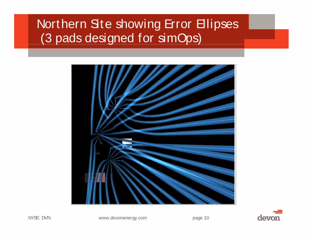
Northern Site showing Error Ellipses(3 pads designed for simOps)( p g p )
NYSE: DVN www.devonenergy.com page 10

Northern Site showing Error Ellipses(3 pads designed for simOps)( p g p )
NYSE: DVN www.devonenergy.com page 11

Typical well profile
The typical well on this project would yp p jkick off around 300 ft with a 2˚/100 ft build. Hold for ~1000-1500 ft. to achieve separation from nearby wells achieve separation from nearby wells. 9 5/8 casing set at ~1000 ft. This was the main source of external magnetic
finterference.
NYSE: DVN www.devonenergy.com page 12

Typical magnetic (BTotal) Profiles (after correction for DSI)
NYSE: DVN www.devonenergy.com page 13

Magnetic MWD Survey Overview
• The survey tool reports Gx, Gy, Gz, and Bx, By, Bz. • From this is calculated Inclination (accelerometers only) Azimuth • From this is calculated Inclination (accelerometers only), Azimuth,
and toolface angle. • QC info reported is GTotal, BTotal, and Magnetic Dip Angle.
Alternatively BH (horizontal) and BV (vertical) magnetic field Alternatively BH (horizontal) and BV (vertical) magnetic field and/or BTotalDip ~ = (sqrt(sumsq(deltaBH, deltaBV))
• Only the horizontal component of B is used in calculating azimuth. Vertical magnetic interference does not change azimuth. Vertical magnetic interference does not change azimuth.
• Only the E-W component of the horizontal interference changes the azimuth
• Only the N-S component of the horizontal interference field • Only the N-S component of the horizontal interference field changes the measured BTotal and Magnetic Dip angle.
• Azimuth changes are caused by horizontal EW interference which cannot be detected. This shows up as azimuth error. cannot be detected. This shows up as azimuth error.
NYSE: DVN www.devonenergy.com page 14

The conundrum of measuring external magnetic interferenceg
• The PROBLEM: • Only the EW horizontal component of magnetic interference causes
azimuth errors• Only the NS horizontal and vertical components can be measured • Only the NS horizontal and vertical components can be measured
using Btotal and Dip QC Measures.
• A SOLUTION:• Use Vertical component to estimate total horizontal field• BH and BV are about the same when averaged over several shots• The QC limits apply to the shots as a group, not individual shots.
BV defines an “envelope” of interference.
NYSE: DVN www.devonenergy.com page 15

How to model casing magnetics
• A simple model is as a string of dipole “bar magnets” joined end to endj
• Any source field can be modeled using monopoles• The pole strength is variable
S f ti ti• Sources of magnetization:– Magnetic inspection (at factory or onsite)– Contact with magnetized collars and drillpipe– Mechanical stresses/shock in a magnetic field
• Steel will distort the earth’s field to some extent.Earth’s field of 0 5 Oersted by itself is not enough – Earth s field of ~0.5 Oersted by itself is not enough to permanently magnetize most steel
• Proper degaussing can minimize the problems. F MPI t t d l t• Few MPI contractors can degauss large parts.
NYSE: DVN www.devonenergy.com page 16
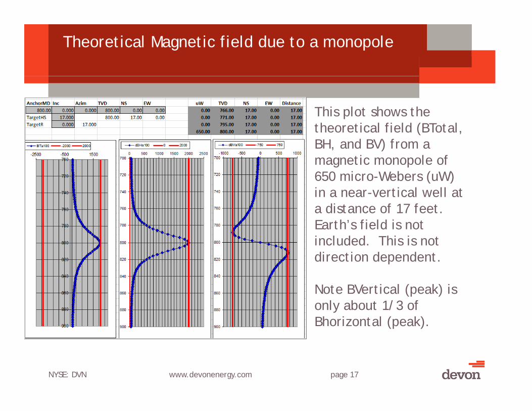
Theoretical Magnetic field due to a monopole
This plot shows the theoretical field (BTotal theoretical field (BTotal, BH, and BV) from a magnetic monopole of 650 micro-Webers (uW) 650 micro Webers (uW) in a near-vertical well at a distance of 17 feet. Earth’s field is not included. This is not direction dependent.
Note BVertical (peak) is only about 1/3 of Bhorizontal (peak).
NYSE: DVN www.devonenergy.com page 17

Simulated Measured field from a 1700 uW Monopole due east in a near-vertical well
NYSE: DVN www.devonenergy.com page 18
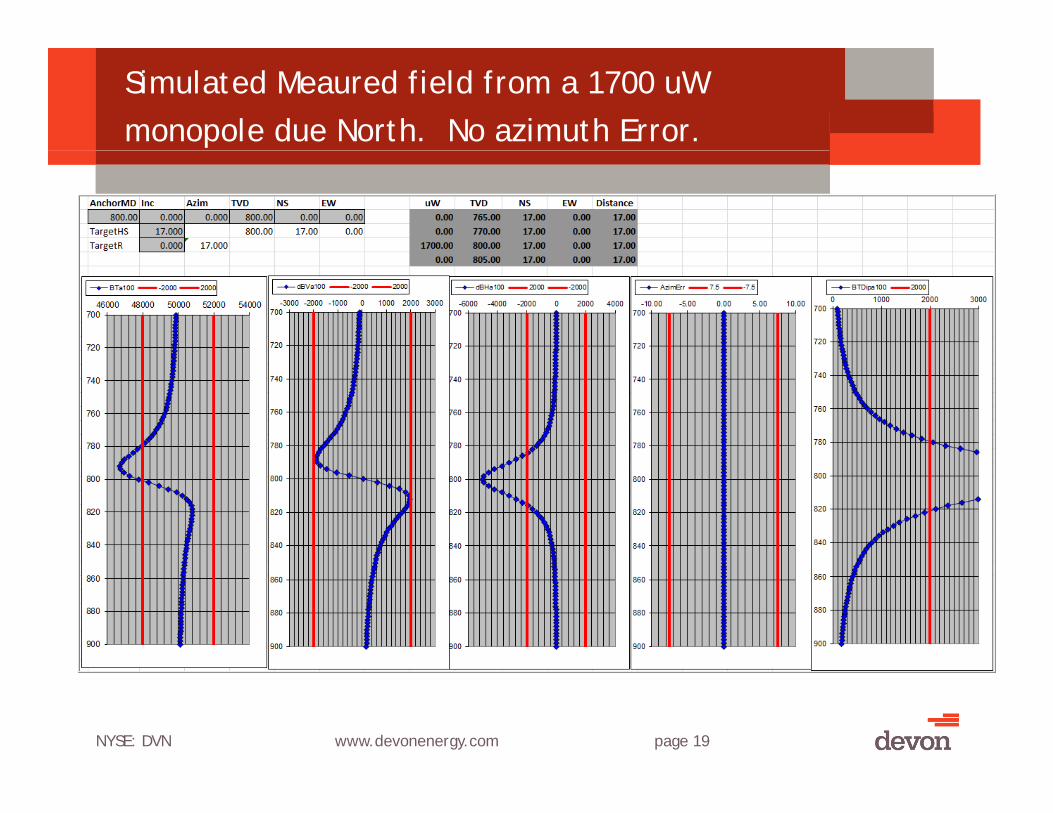
Simulated Meaured field from a 1700 uW monopole due North. No azimuth Error.
NYSE: DVN www.devonenergy.com page 19
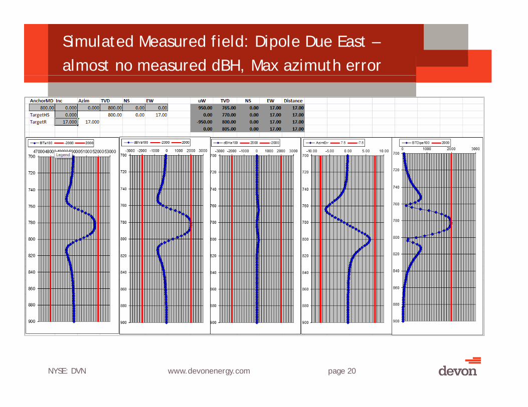
Simulated Measured field: Dipole Due East –almost no measured dBH, Max azimuth error
NYSE: DVN www.devonenergy.com page 20

Simulated Measured field: Dipole Due North –Max Measured delta BH No Azimuth Error
NYSE: DVN www.devonenergy.com page 21
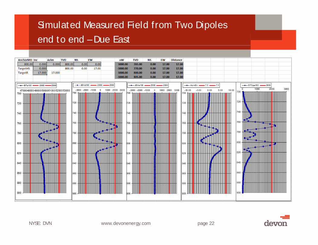
Simulated Measured Field from Two Dipoles end to end – Due East
NYSE: DVN www.devonenergy.com page 22
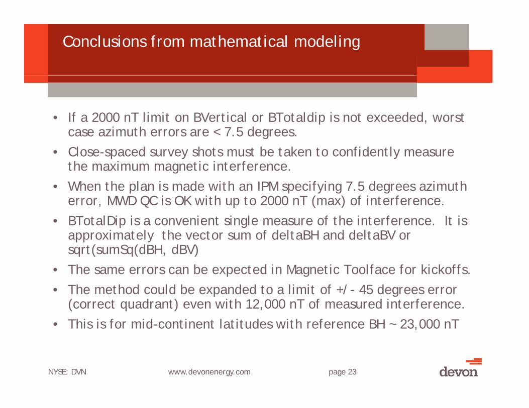
Conclusions from mathematical modeling
• If a 2000 nT limit on BVertical or BTotaldip is not exceeded, worst i h 7 5 d case azimuth errors are < 7.5 degrees.
• Close-spaced survey shots must be taken to confidently measure the maximum magnetic interference.
• When the plan is made with an IPM specifying 7.5 degrees azimuth error, MWD QC is OK with up to 2000 nT (max) of interference.
• BTotalDip is a convenient single measure of the interference. It is l h f d l d d lapproximately the vector sum of deltaBH and deltaBV or
sqrt(sumSq(dBH, dBV)• The same errors can be expected in Magnetic Toolface for kickoffs. • The method could be expanded to a limit of +/- 45 degrees error
(correct quadrant) even with 12,000 nT of measured interference. • This is for mid-continent latitudes with reference BH ~ 23,000 nT
NYSE: DVN www.devonenergy.com page 23

Why this model is very conservative
• The average deltaBV is about the same as deltaBH, not 1/3• Azimuth swing from BH of 2000 nT at mid-latitudes is about 5
degrees, not 7.5• There are an equal number of positive and negative poles q p g p
(Maxwell’s 2nd law – there are no monopoles). The average effect over a large number of survey shots is zero.
• The IPM is applied over the entire section, but the maximum effect l f his seen over only a few shots.
• The assumptions used were worst-case, but an IPM is intended to represent 1 standard deviation.
NYSE: DVN www.devonenergy.com page 24
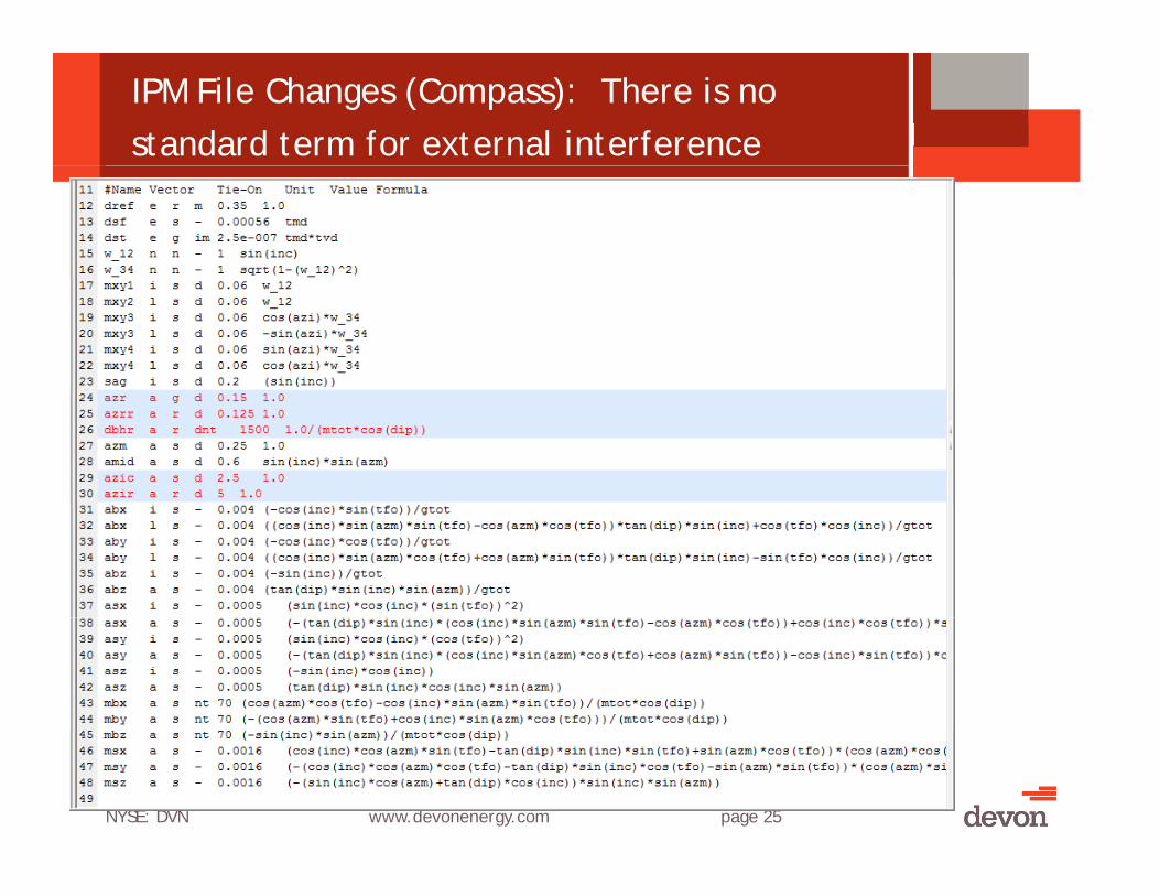
IPM File Changes (Compass): There is no standard term for external interference
NYSE: DVN www.devonenergy.com page 25

IPM File Changes (Compass)
NYSE: DVN www.devonenergy.com page 26
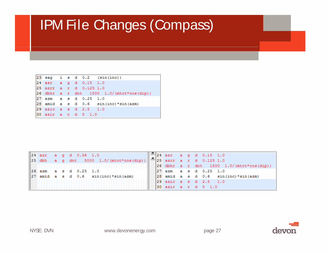
IPM File Changes (Compass)
NYSE: DVN www.devonenergy.com page 27
Recommendations
• Don’t drill near live wells.• Casing should be degaussed before running to minimize interference
with nearby wells. This can be done at the factory or onsite. A low-frequency degaussing method is recommended.
• Drillstring interference (in the Bz direction) must be subtracted. This should be a constant value. This can be minimized by proper degaussing of motors and subs after magnetic inspection.
f f d d b d h• Interference from rig and/or conductor can be expected within 2-300 feet from end of conductor. This is usually before KOP.
• Don’t use single station Z-axis correction methods when there is t l i t f external interference.
• Even if gyro surveys are used, monitor magnetics for unexpected close approaches. Measured interference > 2000 nT is a warning sign.
NYSE: DVN www.devonenergy.com page 28
Thanks & Credits to
• Anne Holmes, Halliburton / Sperry DrillingSteve Grindrod Copsegrove Development• Steve Grindrod, Copsegrove Development
• Mark Michell, now with BHP (Previously Devon Energy)• Shelly Grabb, Devon Energy• Srinivas Karri Reddy (“Reddy”), Halliburton / Sperry Drilling• Tony Williams, Halliburton / Sperry Drilling• Shaun St Louis Pete Schiermeier Halliburton / Sperry Drilling• Shaun St. Louis, Pete Schiermeier, Halliburton / Sperry Drilling• Jim Towle, Scientific Drilling • The Industry Steering Committee for Wellbore Survey Accuracy
(ISCWSA org SPE WPTS) and its members(ISCWSA.org = SPE WPTS) and its members.• Many others especially those who shared their work through SPE
technical papers.
NYSE: DVN www.devonenergy.com page 29

Frequently Asked Questions
Q: Why would you choose to use a less accurate survey method?A:The correct survey choice is the least expensive method that meets the
project objectives.Q: Why was 2000 nT chosen for a QC limit? Why 7.5 degrees error?A 2000 T li it th t f if t d t f il A: 2000 nT was a limit that few if any surveys were expected to fail, so a
gyro would not be required. 7.5 degrees of error gave ellipse sizes that could be easily accommodated in the planning stages. This generous ellipse size gave an extra margin for errors.
Q: Can this be used at higher latitudes?A: The ratio of QC limits to azimuth error would need to be calculated for a
different value of BHorizontal. Q: Isn’t this dangerous?A: Not more than usual, as the ellipse separations were planned for these
large ellipses. The nearby wells were not pressured.

Frequently Asked Questions
Q: Can this be used at closer well to well spacing?A: Each situation requires analysis of the expected interference and q y p
appropriate QC values with corresponding ellipse sizes. These values for closer spacing would probably result in some surveys failing QC.
Q: Doesn’t the “natural” magnetism of the casing (or motor, or drill pipe) come back after degaussing?come back after degaussing?
A: Not if degaussing is done properly and the internal fields in the steel (that cannot be measured) are reduced to near zero. See the following slide and the degaussing theory at http://www.vallon-degaussing.com/products.lasso?a=degaussing
Q: What about Drillstring Interference (in the vertical direction for a near-vertical well)?
A Eith d DSI b d i f ffi i t i A: Either reduce DSI by degaussing or use of sufficient non-mag spacing, or apply a constant (not varying from shot to shot) correction for DSI.
For more info contact Neil Bergstrom@dvn comFor more info contact [email protected]

Degaussing Frequency
Line frequency (50 Line frequency (50 or 60 Hz) does not penetrate a large part. Lower frequency and/or higher fields (amp-g ( pturns) are required
Chart Used with permission
NYSE: DVN www.devonenergy.com page 32
from Vallon-Degaussing.com