Embed Size (px)
Citation preview

PACS – NUMERICAL APPROACH AND EVALUATION OF A CONCEPT FOR DIMENSIONING PRESSURE ACTUATED CELLULAR STRUCTURES
B. Gramüller, C. Hühne DLR - Institute of Composite Structures and Adaptive Systems, Lilienthalplatz 7, Braunschweig, Germany
Abstract
A biologically inspired concept is investigated which can be utilized to develop energy efficient, lightweight and applicational flexible adaptive structures. Summarizing basic demands and barriers regarding shape changing structures, the basic challenges of designing morphing structures are listed. The analytical background describing the physical mechanisms of PACS is presented in detail. This work focuses on the numerical approach of calculating the geometrically highly nonlinear deformation states of pressure actuated cellular structures. Beyond the calculation of equilibrium states a form finding algorithm is presented, which allows determining structural designs following predefined target shapes. Initially made assumptions are dropped incrementally to show the effects on the accuracy of the modeling. FEM-based calculations and experimental test results provide the computational target data for the varying grade of simplifications. Representative of more complex structures, like aircraft control surfaces, the examined geometries are chosen to evaluate the numerical methods and to validate the functionality of the basic working principle.
1. INTRODUCTION
Fluidic actuators can be used to integrally combine an efficient, lightweight and accurate drive system with a deformable structure. The advantages of pneumatic and hydraulic actuators compared with other drive systems are examined by Huber (Huber J. E. et al., 1997). The specific stresses and strains as well as the resolution of motion of this actuators lead to a wide range of use and predestinates it for aeronautical applications. In nature, the combination of fluidic actuation and shape variable structure can be discovered at the special group of nastic plants. Representatives like the thigmonastic Cape Sundew (Drosera Capensis) and Venus Flytrap (Dionaea Muscipula), which use their touch sensing capabilities to trap small insects are examples for a successful implementation of biological integral morphing structures. Another common example is given by the seismonastic Mimosa Pudica that protects its fragile leafage through a folding mechanism when shaken. Sibaoka, investigated the mechanisms of nastic plants. He describes the loss and gain of turgor - internal hydrostatic cell sap pressure - (symbolized by H2O in at the upper right depiction of Figure 1) as the driving force for the distortions (Sibaoka, 1991), which leads to cell pressures of more than 8MPa (Howard, 1991).
Researchers working on form variable cellular structures made huge efforts to adapt this principle to a mechanically usable structural system. Vos et al. developed the Pressure Adaptive Honeycomb (PAH) concept for actuating their Gurney Flap. This trailing edge flap autonomously changes its shape in different flight altitudes and takes advantage of aerostatic pressure differences (Vos R. et al., 2010). Pagitz et al. transferred the idea of fluidic pressure driven morphing structures into a two dimensional concept with a promising degree of deformation, high flexibility and sizeable characteristic (Pagitz M. et al., Pressure-actuated cellular structures, 2012). Compared to the PAH concept, the main difference of PACS consists in the variable side length of its cells. A PACS structure of multiple pressure dependent shapes can be mathematically deduced by manipulating the
equilibrium state of each cell and thereby of the cell compound. Pagitz et al. showed with analytical methods how the deformational shape of such a structure can be controlled for multiple cells and cell rows using flexure hinges (Pagitz M. et al., Compliant Pressure Actuated Cellular Structures, 2014). They established a form finding approach which allows conceiving structures to vary their shapes stepless between multiple form functions.
The applicational flexibility of PACS is demonstrated by the examples of a morphing airfoil and a shape adaptive backrest (Pagitz M. et al., A modular approach to adaptive structures, 2014). With their real life implementation of a single row PACS demonstrator Gramüller et al. showed the practicability of the theoretical basis (Gramüller B. et al., 2014). Figure 1 summarizes the preceding work on shape changing structures using pressurized cellular structures.
2. DEMANDS ON ADAPTIVE STRUCTURES AND DIFFICULTIES
The design of conventional structures is usually driven by two groups of requirements. The first one is of programmatic manner and holds general demands like low costs, high quality and reduced development time. As a second group, structural demands with reference to structural mechanics are determined by the expected loads and in addition by geometrical requirements. These needs are also valid for shape variable structures and a PACS structure has to withstand the design loads and simultaneously ensure to keep deformations in a tolerable range.
The actuation of shape changing structures can be divided in two functional elements, the energy adjusting element (e.g. compressor), which transforms energy (e.g. electrical energy) from the auxiliary energy source into a usable energy form (e.g. pressure and volume) and the energy converter, that modifies the received energy in order to obtain the desired energy driven effects (e.g. deformation) (Janocha, 1992). The special attribute about PACS is the unity of energy converter and structure as shown in chapter 3.
brought to you by COREView metadata, citation and similar papers at core.ac.uk
provided by Institute of Transport Research:Publications

Figure 1: Example from nature: Venus Flytrap (Dionaea Muscipula; left); Concepts of deduced operating principle: (1) PAH (Barrett R. et al., Biomimetic FAA-certifiable, artificial muscle structures for commercial aircraft wings, 2014) and (2) PACS (Pagitz M. et al., Pressure-actuated cellular structures, 2012)
Together with the increased complexity the overall power demands and the additional weight of the energy converter, adjusting element and peripheral sub components like wiring, the first basic problem about shape variable active structures appears. It can be condensed to the following: The development and implementation of a concept for shape changing structures is only reasonable if the anticipated benefit outweighs the invested efforts. Figure 2 specifies this general demand. The energy consumption and related peripheral weight, depends on the required forces and travel ranges needed to deform the structure. Common concepts for aeronautical shape variable structures like the horn concept (Mueller, 2000), the ripless plain flap (Bauer, 2000), the active flexspar actuator (Barrett R. et al., Missile flight control using active, 1996) and the vertebrate structure (Elzey D. et al., 2003) are in need of stiff and weighty structural components to withstand aerodynamic forces. On the contrary Barrett et al. even describe the possibility of reducing structural weight by adaptive structures. An artificial muscle structure based on the pressure driven honeycomb, similarly to PACS benefits of its weight efficient structural integrated actuator and provides the non-concentrated forwarding of distributed aerodynamic loads. Structural hard points can thus be eliminated for further weight reduction and provide an additional contribution to the advantages for airborne applications (Barrett R. et al., Biomimetic FAA-certifiable, artificial muscle structures for commercial aircraft wings, 2014).
Figure 2: Challenge of generating profitable adaptive structures
A raise of structural stiffness increases the sufferable external forces on the corresponding structure but heightens the necessary efforts for changing the structures shape and limits the boundaries of tolerable deformation. Thus the second challenge of developing a profitable morphing concept can be formulated: An efficient concept for shape variable structures circumvents the seeming contradiction of a specific design being stiff and flexible at the same time (see Figure 3). There are some concepts available which have implemented this principle, like the flexible rib from Monner (Monner, 2001), the cellular planar morphing structure from Vasista (Vasista S. et al., 2013), the tendon-actuated compliant cellular trusses (Ramrakhyani D. et al., 2005) or the zigzag wingbox (Ajaj R.M. et al., 2012). The common principle behind these examples is a steered release of specific degrees of freedom (dofs) by integrating hinges, compliant mechanisms or linear bearings.
Figure 3: Challenge of circumventing the dilemma of structural flexibility, stiffness and strength
Other demands on the morphing structure’s actuation element concern its performance-based properties, the maximum forces respectively momentums, e.g. stall torque for an electric motor, and the related travel ranges. Regarding the combination of actuator and structure, the structural response, depending on the actuators characteristics as well as on the structural stiffness and mass distribution, underlies the requirements for control speed and frequency and is essential for the definition of
the operating range of such a concept. Other, not unique airborne subjects as fatigue strength and certification are essential for building a real life morphing structure. Before investigating efforts in these topics, the potentials of a concept for adaptive structures are revealed in this further step of doing research into PACS.
PACS are conceptualized to generate two-dimensional deformations on single-curved surfaces. The conceivable operating range regarding structural dimensions can be varied from centimeters to meters without having any losses of functionality, due to the possibility of adapting certain counteracting design variables. Their potential for future airborne or general structures is based on its lightweight and energetically efficient actuation and design. These properties constitute a good foundation for profitable adaptive structure. The concept is further characterized by a blended structure-actuator construction, possesses a necessary minimum of stiffness in the hinge regions of the cells and generates structural stiffness through pressurization. With a high flexibility in shape variations and an adaptive structural stiffness PACS meets the second challenge for morphing concepts.
3. PHYSICS OF PACS
The analytical equations necessary to find and control the equilibrium state of a pressure actuated cellular structure are essential for understanding the mechanics of this concept. Both proofing the already found analytical results for validity through recalculation and investigating the conceptual boundaries of a realization using compliant hinges, can be reached with the implementation of a respective algorithm. After a summary of the already published information, a continuative approach for the developed implementations is presented. The different strategy beyond that carries new aspects about handling internal and external forces as well as an alternative form finding approach.
3.1. Background
The functional principle of pressure actuated cellular structures is based on the reduction of inner energy due to volume maximization. Figure 4.1 provides a comprehensible visualization of the effects, which lead to the driving forces of this concept. Similar to a flattened balloon, a flexible membrane does not have any defined state of shape without being pressurized. Not until the balloon is loaded with a particular pressure 𝑝1 the resulting
distribution of forces lead onto bending moments and, assuming membrane characteristics, a structural shape of maximum volume. Thus the pressure is minimized (𝑝1 > 𝑝2 > 𝑝3) and equally the inner energy is reduced.
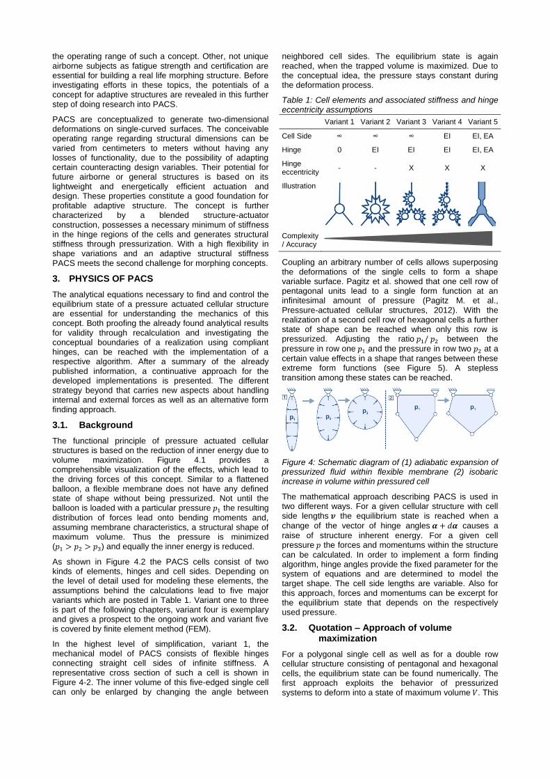
As shown in Figure 4.2 the PACS cells consist of two kinds of elements, hinges and cell sides. Depending on the level of detail used for modeling these elements, the assumptions behind the calculations lead to five major variants which are posted in Table 1. Variant one to three is part of the following chapters, variant four is exemplary and gives a prospect to the ongoing work and variant five is covered by finite element method (FEM).
In the highest level of simplification, variant 1, the mechanical model of PACS consists of flexible hinges connecting straight cell sides of infinite stiffness. A representative cross section of such a cell is shown in Figure 4-2. The inner volume of this five-edged single cell can only be enlarged by changing the angle between
neighbored cell sides. The equilibrium state is again reached, when the trapped volume is maximized. Due to the conceptual idea, the pressure stays constant during the deformation process.
Table 1: Cell elements and associated stiffness and hinge eccentricity assumptions
Variant 1 Variant 2 Variant 3 Variant 4 Variant 5
Cell Side ∞ ∞ ∞ EI EI, EA
Hinge 0 EI EI EI EI, EA
Hinge eccentricity
- - X X X
Illustration
Complexity / Accuracy
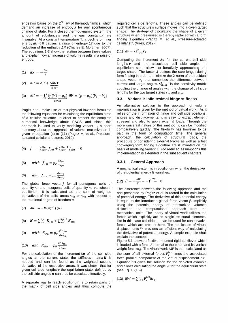
Coupling an arbitrary number of cells allows superposing the deformations of the single cells to form a shape variable surface. Pagitz et al. showed that one cell row of pentagonal units lead to a single form function at an infinitesimal amount of pressure (Pagitz M. et al., Pressure-actuated cellular structures, 2012). With the realization of a second cell row of hexagonal cells a further state of shape can be reached when only this row is pressurized. Adjusting the ratio 𝑝1/ 𝑝2 between the
pressure in row one 𝑝1 and the pressure in row two 𝑝2 at a
certain value effects in a shape that ranges between these extreme form functions (see Figure 5). A stepless transition among these states can be reached.
Figure 4: Schematic diagram of (1) adiabatic expansion of pressurized fluid within flexible membrane (2) isobaric increase in volume within pressured cell
The mathematical approach describing PACS is used in two different ways. For a given cellular structure with cell side lengths 𝒗 the equilibrium state is reached when a
change of the vector of hinge angles 𝜶 + 𝑑𝜶 causes a
raise of structure inherent energy. For a given cell pressure 𝑝 the forces and momentums within the structure
can be calculated. In order to implement a form finding algorithm, hinge angles provide the fixed parameter for the system of equations and are determined to model the target shape. The cell side lengths are variable. Also for this approach, forces and momentums can be excerpt for the equilibrium state that depends on the respectively used pressure.
3.2. Quotation – Approach of volume maximization
For a polygonal single cell as well as for a double row cellular structure consisting of pentagonal and hexagonal cells, the equilibrium state can be found numerically. The first approach exploits the behavior of pressurized systems to deform into a state of maximum volume 𝑉. This
endeavor bases on the 2nd
law of thermodynamics, which demand an increase of entropy 𝑆 for any spontaneous
change of state. For a closed thermodynamic system, the amount of substance 𝑛 and the gas constant 𝑅 are
invariable. At a constant temperature T, a decline of inner energy ∆𝑈 < 0 causes a raise of entropy ∆𝑆 due to the
reduction of the enthalpy ∆𝐻 (Charles E. Mortimer, 2007).
The equations 1-3 show the relation between these values and explain how an increase of volume results in a raise of entropy.
(1) ∆𝑆 = −∆𝐻
𝑇
(2) ∆𝐻 = ∆𝑈 + ∆nRT⏟ 𝑐𝑜𝑛𝑠𝑡
(3) ∆𝑈 = −∫ (𝑝(𝑉) − 𝑝𝑢)⏟ 𝑐𝑜𝑛𝑠𝑡
𝜕𝑉2
1= (𝑝 − 𝑝𝑢)(𝑉1 − 𝑉2)
Pagitz et.al. make use of this physical law and formulate the following equations for calculating the equilibrium state of a cellular structure. In order to present the complete numerical knowledge about PACS and since this approach is used to verify modeling variant 1, a short summary about the approach of volume maximization is given in equation (4) to (11) (Pagitz M. et al., Pressure-actuated cellular structures, 2012).
(4) 𝒇 = ∑ 𝒇𝑃𝑛𝑛𝑃𝑛=1 +∑ 𝒇𝐻𝑛
𝑛𝑃−1𝑛=1 = 0
(5) 𝑤𝑖𝑡ℎ 𝒇𝑃𝑛 = 𝑝𝑃𝜕𝐴𝑃𝑛
𝜕𝒖𝑃𝑛
(6) 𝑎𝑛𝑑 𝒇𝐻𝑛 = 𝑝𝐻𝜕𝐴𝐻𝑛
𝜕𝒖𝐻𝑛
The global force vector 𝒇 for all pentagonal cells of
quantity 𝑛𝑃 and hexagonal cells of quantity 𝑛𝐻 vanishes in equilibrium. It is calculated as the sum of weighted derivatives of the cells’ areas 𝐴𝑃𝑛 or 𝐴𝑃𝑛 with respect to
the rotational degree of freedom 𝒖.
(7) 𝛥𝒖 = −𝑲(𝒖)−1𝒇(𝒖)
(8) 𝑲 = ∑ 𝑲𝑃𝑛𝑛𝑃𝑛=1 + ∑ 𝑲𝐻𝑛
𝑛𝑃−1𝑛=1
(9) 𝑤𝑖𝑡ℎ 𝑲𝑃𝑛 = 𝑝𝑃𝜕2𝐴𝑃𝑛
𝜕𝒖𝑃𝑛2
(10) 𝑎𝑛𝑑 𝑲𝐻𝑛 = 𝑝𝐻𝜕2𝐴𝐻𝑛
𝜕𝒖𝐻𝑛2
For the calculation of the increment Δ𝒖 of the cell side angles at the current state, the stiffness matrix 𝑲 is
needed and can be found as the weighted second derivative of the respective areas. It was shown that for given cell side lengths 𝒗 the equilibrium state, defined by
the cell side angles 𝜶 can thus be calculated iteratively.
A separate way to reach equilibrium is to retain parts of the matrix of cell side angles and thus compute the
required cell side lengths. These angles can be defined such that the structure’s surface moves into a given target shape. The strategy of calculating the shape of a given structure when pressurized is thereby replaced with a form finding algorithm (Pagitz M. et al., Pressure-actuated cellular structures, 2012):
(11) ∆𝒗 = 𝜆𝑺𝑡1,𝑡2𝑇 𝒓𝑆
Computing the increment ∆𝒗 for the current cell side
lengths 𝒗 and the associated cell side angles in
equilibrium state allows to iteratively approaching the target shape. The factor 𝜆 defines the step length during
form finding in order to minimize the 2-norm of the residual shape vector 𝒓𝑆 that comprises the difference between
current and target angles. 𝑺𝑠𝑡1,𝑠𝑡2𝑇 is the sensitivity matrix
coupling the change of angles with the change of cell side lengths for the two target states 𝑠𝑡1 and 𝑠𝑡2.
3.3. Variant 1: Infinitesimal hinge stiffness
An alternative solution to the approach of volume maximization is given by the method of virtual work. As it relies on the information of hinge and cell side positions, angles and displacements, it is easy to extract element stresses and also to apply external loads. Through the more universal nature of this method, it can be modified comparatively quickly. The flexibility has however to be paid in the form of computation time. The general approach, the calculation of structural loads, the procedure of considering external forces as well as a fast converging form finding algorithm are illuminated on the basis of modeling variant 1. For reduced assumptions this implementation is extended in the subsequent chapters.
3.3.1. General Approach
A mechanical system is in equilibrium when the derivative of the potential energy 𝛱 vanishes:
(12) �̇� = −𝛿𝑊
𝛿𝑟= −𝒇 =
𝑒𝑞𝑢𝑖𝑙.0
The difference between the following approach and the one presented by Pagitz et al. is rooted in the calculation of potential energy. The derivative of this potential energy is equal to the introduced global force vector 𝒇. Implicitly using the potential energy of pressurized volumes dislocates the computational approach from the mechanical units. The theory of virtual work utilizes the forces which explicitly act on single structural elements, like in this case cell sides. It can be used for conservative forces which are present here. The application of virtual displacements 𝛿𝑟 provides an efficient way of calculating
the derivative of potential energy. A simple example shall explain the concept. Figure 5.1 shows a flexible mounted rigid cantilever which is loaded with a force 𝐹 normal to the beam and its vertical weight force 𝑚𝑔. The virtual work Δ𝑊 is then calculated as
the sum of all external forces 𝑭𝑖(𝑒)
times the associated
force parallel component of the virtual displacement Δ𝒓𝑖. Equation 13 gives the solution for the depicted example and allows calculating the angle 𝛼 for the equilibrium state
(see Eq. 15(15)).
(13) δ𝑊 = ∑ 𝑭𝑖(𝑒)δ𝒓𝑖
𝑛𝑖=1

(14) δ𝑊 = [F −1
2mgsin (𝛼)] aδ𝛼
(15) δ𝑊
δ𝛼=
𝑒𝑞𝑢𝑖𝑙.0, 𝑓𝑜𝑟 𝛼𝑒𝑞 = asin (
2𝐹
𝑚𝑔)
For a pressurized single cell of 𝑗 = [𝑚] cell sides the
equilibrium shape can be found equally. The cell’s geometry in a two dimensional space is determined by a matrix of cell side lengths 𝒗 with size [𝑚] and a matrix of
rotational dofs 𝒖 with size 𝑘 = [𝑚 − 3]. To find the equilibrium state for a given PACS the cell side lengths provide the known and the rotational dofs or cell side angles the unknown variables. Figure 5.2 shows the notation of the variables for a single cell with the pressure load 𝑝.
Figure 5: Principle of virtual work, applied to a rigid cantilever and an n-edge cell
The cell side vectors are
(16) 𝒂𝑗 = [𝑎𝑗,𝑥 𝑎𝑗,𝑦], 𝑤𝑖𝑡ℎ |𝒂𝑗| = 𝑣𝑗.
Assuming infinite stiffness for cell sides and flexible hinges the force vector is computed with the unit vector 𝒆3 to
(17) 𝑭𝑗 = 𝑝𝑣𝑗 [𝒂𝑗
‖𝒂𝑗‖× 𝒆3] = 𝑝[𝒂𝑗 × 𝒆3].
The local virtual displacement vector δ𝒙 is computed as a
function of the virtual displacement at the rotational dof δ𝑢𝑘 and illustrated in Figure 6. It is determined as the
displacement at the center of each cell side due to the displacement δ𝑢𝑘:
(18) δ𝒙𝑗,𝑘 = 𝑔(𝒗, 𝒖, δ𝑢𝑘)
The function 𝑔() holds the trigonometric terms necessary
to describe a polygon with the parameters 𝒗 and 𝒖 which
can be found in the work of Pagitz et al. (Pagitz M. et al., Pressure-actuated cellular structures, 2012). With the additional information about the virtual displacement δ𝑢𝑘
at hinge 𝑘 the displacement of the point of origin for the
resultant force vector 𝑭𝑗, δ𝒙𝑗,𝑘 is calculated.
The vector quantity of the force parallel virtual displacement is formed by the vertical projection of the local displacement on the local force:
(19) δ𝑟𝑗,𝑘 =δ𝒙𝑗,𝑘∙𝑭𝑗
‖𝑭𝑗‖2
The first derivative of the potential energy can be
computed to
(20) �̇�𝑘 = −𝛿𝑊𝑘
δ𝑢𝑘= −
∑ 𝐹𝑗δ𝑟𝑗,𝑘𝑚𝑗=1
δ𝑢𝑘= −𝑓𝑘 = 0.
In order to solve this equation and find the equilibrium shape of the cellular structure the Newton’s method with quadratic convergence for this system provides a valuable approach. This iterative solution is chosen because of its flexibility with respect to an arbitrary number of cell sides as well as to multiple cells:
(21) 𝑥𝑛+1 = 𝑥𝑛 −𝑓(𝑥𝑛)
�̇�(𝑥𝑛) (Newton’s method)
Figure 6: Schematic description of the kinematical correlations of an m-edged single cell used for the approach of virtual work
The current state variable 𝒖𝑡+1 for the iteration step 𝑡 + 1
results from the following equation:
(22) 𝒖𝑡+1 = 𝒖𝑡 −�̇�
𝜕�̇�/𝜕𝒖= 𝒖𝑡 − �̇�𝑲
−𝟏
The second derivative of the potential energy is needed to calculate the stiffness matrix 𝑲 (cf. Eq. 23). The size of 𝑲
is [𝑚 − 3 × 𝑚 − 3].
(23) 𝑲 =𝜕�̇�
𝜕𝒖=
[
𝜕�̇�1
𝜕𝑢1
𝜕�̇�1
𝜕𝑢2
𝜕�̇�2
𝜕𝑢1
𝜕�̇�2
𝜕𝑢2
⋯
𝜕�̇�1
𝜕𝑢𝑚−3
𝜕�̇�2
𝜕𝑢𝑚−3
⋮ ⋱ ⋮𝜕�̇�𝑚−3
𝜕𝑢1
𝜕�̇�𝑚−3
𝜕𝑢2⋯
𝜕�̇�𝑚−3
𝜕𝑢𝑚−3]
The equilibrium state for an m-edged single cell is thus found. Applied to a cellular structure of 𝑖 = 𝑛 cells these
equations keep their validity and can be superimposed to describe more complex structures. Depending on the kind of cell combination the number of independent state variables alternates and thus the size of the stiffness matrix does. For a double row PACS structure of 𝑖1 = 𝑛𝑃
pentagonal and 𝑖2 = 𝑛𝐻 hexagonal cells, which Pagitz et

al. described in their publication, the number of independent variables reduces to [𝑛𝑃(𝑚𝑃 − 3)] +[𝑛𝐻(𝑚𝐻 − 3 − 2) + 1] = 2𝑛𝑃 + 𝑛𝐻 + 1 what is equal to 3𝑛𝑃.
Figure 7 shall illuminate this assertion.
Figure 7: Reduction of the number of independent state variables due to geometrical coupling
Similarly to the computation of the equilibrium for the single cell, the derivative of the potential energy is built by
(24) �̇�𝑖,𝑘 = −𝛿𝑊𝑖,𝑘
δ𝑢𝑖,𝑘= −
∑ 𝐹𝑖,𝑗δ𝑟𝑖,𝑗,𝑘𝑚𝑗=1
δ𝑢𝑖,𝑘.
The stiffness matrix 𝑲 for this example has the size [3𝑛𝑃 ×3𝑛𝑃] and can still be deduced from the derivative of the potential work after the state variable vector 𝒖:
(25) 𝑲 =𝜕�̇�
𝜕𝒖=
[
𝜕�̇�1,1
𝜕𝑢1
𝜕�̇�1,1
𝜕𝑢1,2
𝜕�̇�1,2
𝜕𝑢1
𝜕�̇�1,2
𝜕𝑢2
⋯
𝜕�̇�1,1
𝜕𝑢𝑛,𝑚𝑛−3
𝜕�̇�1,2
𝜕𝑢𝑛,𝑚𝑛−3
⋮ ⋱ ⋮𝜕�̇�𝑛,𝑚𝑛−3
𝜕𝑢1
𝜕�̇�𝑛,𝑚𝑛−3
𝜕𝑢2⋯
𝜕�̇�𝑛,𝑚𝑛−3
𝜕𝑢𝑛,𝑚𝑛−3]
3.3.2. Calculation of stresses
For the structural design of PACS as well as for the appraisal of use-dependent practicability stress values provide the necessary input. The computation of stresses is also processed using the method of virtual work. Equal to the virtual rotation 𝛿𝑢 a virtual displacement 𝛿𝑣 of cell
side lengths causes the virtual work 𝛿𝑊. The quotient of
virtual work and virtual displacement yields to the force value within the observed cell side:
(26) �̇�𝑗 = −𝛿𝑊𝑗
δ𝑣𝑗= −
∑ 𝐹𝑗δ𝑟𝑗𝑚𝑗=1
δ𝑣𝑗= −𝑓𝑗 = 0
Depending on the respective wall thickness 𝑡𝑗, the cell
side stress for a PACS cell of depth 1 is
(27) 𝜎𝑗 =𝑓𝑗
𝑡𝑗.
For all of the subsequent depictions showing structural stresses a wall thickness of 1 is underlying.
3.3.3. External forces
Equally to the pressure induced forces external loads of number 𝑛𝑒, if present, are considered by calculating the
product of external force 𝐹𝑒𝑥𝑡 times the related virtual
displacement δ𝑟𝑒𝑥𝑡:
(28) �̇�𝑘 = −(𝛿𝑊𝑗
δ𝑢𝑘+𝛿𝑊𝑒𝑥𝑡
δ𝑢𝑘) =
−∑ 𝐹𝑗δ𝑟𝑗,𝑘𝑚𝑗=1 +∑ 𝐹𝑒𝑥𝑡,ℎδ𝑟𝑒𝑥𝑡,ℎ,𝑘
𝑛𝑒ℎ=1
δ𝑢𝑘= 0
3.3.4. Form Finding
The difference between finding the equilibrium state of a given PACS structure and calculating the structure for a desired shape variation lies in the set of known and unknown variables. As visualized in Figure 8 the outer shape of PACS can be defined by one angle per pentagonal cell plus one additional angle for the connector cell side of the last pentagonal cell. For a double row cantilever with two attainable shape functions at the pressure sets 𝑠𝑡1 and 𝑠𝑡2, 2(𝑛𝑝 + 1) known variables are
given. The vector of known variables is 𝒖𝟎. The mixed
vector of unknown state variables 𝒘 whereas consists
of 𝑛𝑝 − 1 pentagon and 𝑛ℎ + 1 hexagon angles
summarized in 𝒖𝟏 and 4𝑛𝑝 + 1 pentagonal and 3𝑛ℎ + 1
hexagonal cell side lengths 𝒗.
Figure 8: Known variables at pressure set 𝑝𝑠𝑡1 for the form finding approach
(29) 𝒖 = [𝒖𝟎𝒖𝟏] ; 𝒘 = [
𝒖𝟏𝒗]
The first derivative of the virtual work is again found according to equation (24) as the equilibrium state still has to fulfill equation (20). Thus the unknown variables add up to 9𝑛𝑝 this number is three times higher than the number
of equations from (20), 3𝑛𝑝. Multiple solutions exist which
fulfill the demand of two shape states at the related pressures. An algorithm that mathematically combines unknown variables can thus be used to control the cells shape in order to additionally handle manufacturing requirements or external geometrical boundary conditions.
Pagitz et al. presented a method for the form finding of PACS structures that is based on computing a sensitivity matrix which relates the change of rotational dofs to the change of cell side lengths (Pagitz M. et al., Pressure-actuated cellular structures, 2012). The initial state of 𝒖𝟎 is
chosen to be identical with the manufacturing state. A number of 2,000 to 20,000 iterations are necessary to find the shape of an optimized structure with an accuracy of at least 0.01° related to the target values (Pagitz M. et al., Compliant Pressure Actuated Cellular Structures, 2014).
A novel approach for solving the form finding problem for a PACS structure reduces the required number of iterations

significantly. In contrast to evaluating the deviation between current and target cell angles after each iteration step, the residual energy potential of the structure is used to compute the increment for the change of cell side lengths. This allows to additionally coupling the change of unknown rotational dofs 𝒖𝟏 to the change of cell side
lengths 𝒗. For an initial state the target shapes 𝑠𝑡1 and 𝑠𝑡2 are used. The stop criterion from the approach of calculating a PACS structure’s equilibrium state is still valid and leads to a maximum angular deviation towards target geometry of 1.90e-7° for the example shown in Figure 10. The target shapes are characterized by an angular deflection of ±5° per pentagonal cell. The related pressure sets can be obtained from the respective depiction.
Figure 9 shows the convergence behavior in dependency of the hinge stiffness, which is introduced in the following section. The number of iterations needed to fulfill the stop criterion for the remaining virtual work is equal for calculating the equilibrium state and for form finding assuming infinitesimal hinge stiffness. As the change of the manufacturing state of the structure and thus the change of initial cell side angles are also coupled to the change of cell side lengths, a non-zero hinge stiffness does not substantially raise the necessary number of iterations.
Figure 9: Convergence curve for exemplary structure extracted from the form finding procedure for infinitesimal and finite hinge stiffness
Similar to equation (22) the mixed vector of unknown state variables 𝒘 is computed by
(30) 𝒘𝑡+1 = 𝒘𝑡 −�̇�
𝜕�̇�/𝜕𝒘= 𝒘𝑡 − �̇�𝑺
−𝟏.
where 𝑺 is the sensitivity matrix which relates the change
of unknown variables to the virtual work and thereby to the remaining energy potential. It is calculated at the equilibrium state of 𝒖𝟏, where
(31) �̇� = −𝛿𝑾
δ𝒖𝟏= 0,
by
(32) 𝑺 =𝜕2𝜫
𝜕𝒖𝜕𝒘=
𝜕�̇�
𝜕𝒘=
[ 𝜕�̇�1,𝑠𝑡1
𝜕𝑢1,1
𝜕�̇�2,𝑠𝑡1
𝜕𝑢1,1
⋯
𝜕�̇�1,𝑠𝑡1
𝜕𝑢1,2𝑛𝑝−1
𝜕�̇�1,𝑠𝑡1
𝜕𝑣1
𝜕�̇�2,𝑠𝑡1
𝜕𝑢1,2𝑛𝑝−1
𝜕�̇�2,𝑠𝑡1
𝜕𝑣1
⋯
𝜕�̇�1,𝑠𝑡1
𝜕𝑣7𝑛𝑝−1
𝜕�̇�2,𝑠𝑡1
𝜕𝑣7𝑛𝑝−1
⋮ ⋱ ⋮ ⋱ ⋮𝜕�̇�3𝑛𝑝,𝑠𝑡1
𝜕𝑢1,1⋯
𝜕�̇�3𝑛𝑝,𝑠𝑡1
𝜕𝑢1,2𝑛𝑝−1
𝜕�̇�3𝑛𝑝,𝑠𝑡1
𝜕𝑣1⋯
𝜕�̇�3𝑛𝑝,𝑠𝑡1
𝜕𝑣7𝑛𝑝−1_________________________________________________𝜕�̇�1,𝑠𝑡2
𝜕𝑢1,1
𝜕�̇�2,𝑠𝑡2
𝜕𝑢1,1
⋯
𝜕�̇�1,𝑠𝑡2
𝜕𝑢1,2𝑛𝑝−1
𝜕�̇�1,𝑡𝑠2
𝜕𝑣1
𝜕�̇�2,𝑠𝑡2
𝜕𝑢1,2𝑛𝑝−1
𝜕�̇�2,𝑠𝑡2
𝜕𝑣1
⋯
𝜕�̇�1,𝑠𝑡2
𝜕𝑣7𝑛𝑝−1
𝜕�̇�2,𝑠𝑡2
𝜕𝑣7𝑛𝑝−1
⋮ ⋱ ⋮ ⋱ ⋮𝜕�̇�3𝑛𝑝,𝑠𝑡2
𝜕𝑢1,1⋯
𝜕�̇�3𝑛𝑝,𝑠𝑡2
𝜕𝑢1,2𝑛𝑝−1
𝜕�̇�3𝑛𝑝,𝑡2
𝜕𝑣1⋯
𝜕�̇�3𝑛𝑝,𝑠𝑡2
𝜕𝑣7𝑛𝑝−1 ]
.
The inverse of the sensitivity matrix is computed according to the Moore-Penrose method. For the present case of a non-quadratic matrix, this approach minimizes the 2-norm
of �̇�𝑺−𝟏 and leads to stable convergence behavior.
Compared to Figure 8 the structure depicted in Figure 10 shows three additional elements which came up to be important during the work on the realization of a PACS structure (Gramüller B. et al., 2014). Finite hinge stiffness and eccentric hinge positions are described in the further chapters. The connection concept at both ends of the cantilever is needed for clamping a real life structure to its test bench or to connect multiple PACS units. It is developed together with M. Pagitz et al. (Pagitz M. et al., A modular approach to adaptive structures, 2014).
Figure 10: Resulting structure from the form finding procedure after nine iterations for E=2.0GPa
3.4. Variant 2: Finite hinge stiffness
In contrary to the previously shown approach the cells of nastic plants do not dispose of discrete hinges of infinitesimal stiffness. Though a man-made structure can be built which most widely satisfies this assumption by using pinned hinge joints, compliant mechanisms hold two essential advantages. According to the functionality of a plant cell a compliant PACS cell is pressure-sealed in radial direction without any auxiliary structure. Beyond that the integral design of a compliant PACS saves weight and

substitutes the respective assembly process. Both for the calculation of the pressure dependent shape of a given PACS structure and for the form finding process, the integration of a finite hinge stiffness in the numerical model enhances the results. As this section extends the already presented approach the equations of chapter 3.3 are still valid and necessary.
The equivalent stiffness for a compliant hinge joint can be calculated by considering the hinge to be a beam with the flexural stiffness 𝐸𝐼. This beam of length 𝑠𝑙 and
thickness 𝑡𝑙 (see Figure 11) holds the torsional stiffness 𝑐𝑙 at the non-coupled (independent state variables and dependent dofs, cf. Figure 7) hinge 𝑙. The size of 𝒄 is [9𝑛𝑝 + 1]. For a material of Young’s modulus 𝐸 it results
in
(33) 𝑐𝑙 =𝐸𝐼𝑧,𝑙
𝑠𝑙= 𝐸
𝑡𝑙3
12𝑠𝑙.
As depicted in Figure 11 conjugated eccentric hinges ℎ1
and ℎ2 are combined by:
(34) 𝑐𝑙 =1
1/𝑐𝑙,ℎ1+1/𝑐𝑙,ℎ2+1/𝑐𝑙,ℎ3.
Figure 11: Compliant hinge element with wall thickness t and length s
The formula for calculating the virtual work 𝛿𝑊𝑘 has to be extended by the approach of torsional stiffness and completed by the resulting distortion dependent momentums. The updated virtual work is
(35) 𝛿𝑊𝑘 = ∑ 𝐹𝑗δ𝑟𝑗,𝑘𝑚𝑗=1 + ∑ 𝑐𝑙(∆𝑢𝑡,𝑙δ𝑢𝑙,𝑘 +
1
2δ𝑢𝑙,𝑘
2 )𝑞𝑙=1 ,
(36) 𝑤𝑖𝑡ℎ ∆𝑢𝑡,𝑙 = 𝑢𝑡,𝑙 − 𝑢0.
The angular deflection ∆𝑢𝑡,𝑙 at the iteration step 𝑡 is equal
to the difference of the non-coupled angle 𝑢𝑡,𝑙 and the
manufactured hinge angle 𝑢0 of the unloaded structure.
As 𝑐𝑙 depends on the structural design and is constant and
the varieties of 𝑢𝑙 are already part of the existing
calculations, the computation time is not much affected by this supplement. The approach of virtual work further allows adding this sub-formula without huge changes in the overall code.
3.5. Variant 3: Eccentric hinges
Without a novel approach for describing mechanical element properties variant 3 provides a remedy for the assumption of locally concentrated one-dimensional hinge elements. In a real-life PACS structure the hinge length
varies between five and twenty percent of the cell size. As the center of a compliant hinge not always coincides with the intersection point of linked cell sides, the dislocation of the effective hinge positions can be on the same scale. Figure 12 gives an example for unavoidable eccentricity of hinge joints. Two possibilities for the design of compliant hinges in the crossover point of three interconnected cell sides are shown for a GFRP (glass fiber-reinforced plastic) cell with the size of fifty millimeters. It can be obtained that at this crossover an accumulation of material increases bending stiffness. The effective hinge location migrates to an eccentric position.
Figure 12: Eccentric compliant hinges at crossing points of adjacent cells
Overriding the approximation of concentrated hinges claims the implementation of eccentric hinge elements and leads to a more precise modeling of the real structure.
In order to keep the number of additional unknown variables small and considering computation time, the eccentric hinge is modeled as rigid triangle with fixed side lengths and only one rotational dof 𝒖𝜁. In the context of the
approach of virtual work, a suitable way to describe this triangle is depicted in Figure 13. The vector of eccentricity 𝜻𝑖,𝑙 at cell 𝑖 and hinge 𝑙 defines the geometry of
the element. Together with the angle 𝒖𝜁0 the initial state
for the eccentric hinge is defined.
Figure 13: Definition and notation of eccentric hinge element
The vector 𝒖 which contains the state variables for
pentagonal and hexagonal cells has to be extended by rotation angle 𝒖𝜁. The number of independent variables
thus increases by 4𝑛𝑝 − 4 to 7𝑛𝑝 − 4. The equations for
calculating the vector of virtual work, stiffness and sensitivity matrices are still valid. The adaption of 𝒖
however leads to a new size of these arrays. The form finding approach described in chapter 3.3.4 is also

applicable for eccentric compliant hinges. Figure 10 depicts an exemplary double row PACS structure calculated on the basis of variant 3.
3.6. Variant 5: FEM-based approach
The benefit of the reduction of assumptions and a more detailed modeling method shall be shown. Thereby the available variants can be assessed having regard to the computation complexity. The FEM tool Ansys is used to calculate the deformations of a pressurized reference PACS structure. As this model is built of three-dimensional linear solid elements including axial and bending stiffness, this FEM-based approach provides the most reliable data. The outcomes are thereby used as a reference for the resulting deformation data of the alternative methods.
The target structure is a double row cantilever designed to suit a modular concept. It consists of six pentagonal and five plus two hexagonal cells. The length of the cantilever is 350mm. Two separate regions are defined for meshing the structure. The cell sides elements are determined to have an element size of 2mm, hinge regions are modeled with a refined element size of 0.3mm – see Figure 14.
Figure 14: Visualization of the FEM model for the modular double row cantilever
4. EVALUATION
4.1. Verification of variant 1
The deformation and stress results for a loaded cantilever calculated according to variant 1 (cf. Table 1) are compared with the publicized results from Pagitz et al. (Pagitz M. et al., Pressure-actuated cellular structures, 2012). Despite the completely different analytical formulations the results show good correspondence. Figure 15 pictures the deformed cantilever including cell side stresses for method of volume maximization (VM) - left - and virtual work (VW) - right. Deviations of colors are due to varying imaging procedures what is made clear in following quantitative exposition.
Figure 15: Visual comparison of deformational and stress results between the approach of volume maximization – left - and virtual work – right
For this approach of virtual work a virtual rotation of 𝛿𝑢 =
2𝑒 − 6 is used. |�̇�| < 1𝑒 − 5 is chosen as stop criterion for
the iteration.
Table 2 and Table 3 show the quantitative values for hinge positions and cell side normal stresses for the rightmost pentagonal cell of the depicted cantilever. The different pressurization conditions are identified by 𝑠𝑡1 and 𝑠𝑡2. The
numbering of hinge points and cell sides can be obtained from Figure 15. The maximum relative deviation of 2.18e-5 for hinge coordinates and 1.12e-5 for stresses results. The validity of the approach of virtual work is thus verified.
Table 2: Hinge coordinates at equilibrium state for volume maximization - VM - and virtual work - VW
HingePos 28 29 30 31 32
xst1,VM[mm] 634.7420 648.7360 706.0260 628.0109 677.3280
xst1,VW[mm] 634.7526 648.7465 706.0382 628.0246 677.3419
yst1,VM[mm] 497.7787 496.9998 553.0957 597.5519 605.7876
yst1,VW[mm] 497.7714 496.9911 553.0862 597.5448 605.7789
xst2,VM[mm] 884.3763 884.3378 937.0112 984.3722 989.0510
xst2,VW[mm] 884.3754 884.3366 937.0098 984.3712 989.0498
yst2,VM[mm] -157.5712 -207.5713 -236.3032 -156.6585 -206.4391
yst2,VW[mm] -157.5725 -207.5725 -236.3046 -156.6603 -206.4406
Table 3: Cell side stresses at equilibrium state for volume maximization - VM - and virtual work - VW
CellSide 37 38 39 40 41
σst1,VM[MPa] -29.4297 33.7915 192.5062 193.2165 17.8448
σst1,VW[MPa] -29.4297 33.7915 192.5066 193.2167 17.8446
σst2,VM[MPa] 42.7883 204.0862 133.5500 131.7476 98.2794
σst2,VW[MPa] 42.7882 204.0865 133.5502 131.7478 98.2794
4.2. Comparison of differing modeling variants
Differences in accuracy of the three presented implementations utilizing the method of virtual work are illuminated in this exemplary comparison. The outcomes summarize the presented work on the numerical computation of PACS and assess the quality of the obtained results according to the concomitant efforts. The pressure set-up is chosen to cover both, a state of shape near the geometrical convergence which requires high pressures (I) and the case where the geometry is not converged and sensitive to slight pressure changes (II).

The FEM data described in chapter 3.6 is used as reference for calculating deviations. Table 4 comprises the quantitative values for the rotational deformation at the first cell side of the sixth pentagonal cell as well as the percentage variance in relation to FEM data. An improvement of accuracy from +37.14% to 9.47% for the first pressure setting and from +85.88 to +0.59 for the second one clearly confirms the benefit of increased modeling complexity. Especially in low pressure regions, which are characterized by a non-converged geometrical deformation, the modeling methods including infinite hinge stiffness provide superior results. This can be explained by the stiffening of the overall structure and a decreasing sensitivity against non-pressure induced forces with rising cell pressures. The eccentricity of the hinge points directly affects the energetic potential of the pressured cellular structure. The significant impact on the accuracy of computational results is quantified. Figure 16 visualizes the outcomes.
Table 4: Rotational deformation at cell side one of the sixth pentagonal cell for the three presented modeling variants and deviations from FEM results
Variant 1 Variant 2 Variant 3 Variant 5
∆𝛽6,1,𝑝𝐼 [°] 35.04 29.80 27.97 25.55
𝜂𝑉𝑥,𝐹𝐸𝑀,𝑝𝐼 [%] +37.14 +16.63 +9.47 -
∆𝛽6,1,𝑝𝐼𝐼 [°] 6.32 2.86 3.42 3.40
𝜂𝑉𝑥,𝐹𝐸𝑀,𝑝𝐼𝐼 [%] +85.88 -15.88 +0.59 -
Figure 16: Visualization of deformations from the four types of numerical computation for two different pressure set-ups
4.3. Validation by experimental investigations
The deformation results delivered by the most accurate numerical non-FEM method, the eccentric hinge approach are compared with the outcomes of the investigation of the only existing real-life PACS structure. To simplify manufacturing all of the cells are designed to have the same dimensions. A GFRP single row cantilever consisting of six cells of width 50mm and length 450mm results that reaches an entire span of 300mm. The main reasons for this demonstrator are to prove the theoretical
methods about this concept for its practicability and to evaluate the calculation results. The design process and manufacturing strategy of this prototype is part of a previous publication (Gramüller B. et al., 2014). In favor of further examinations the physical implementation of a double row demonstrator is in progress.
For the given PACS geometry built from the GFRP material HexPly913 with a Young’s modulus of 𝐸 =42.0𝐺𝑃𝑎 an averaged hinge eccentricity of 𝜁𝑖,𝑙,𝑥 = 4𝑚𝑚,
the resulting hinge stiffness of 𝑐𝑖,𝑙 = 10.938. . .27.344𝑁
𝑟𝑎𝑑
and the pressure 𝑝 = 0.2𝑀𝑃𝑎, numerical calculations are
processed. Table 5 contains the deformation results for the first cell side of the sixth cell. A deviation of 1.013% shows a good match between numerical - according to variant 3 - and experimental data and confirms the previous insights. The experimental value is measured with an analogue protractor.
Table 5: Comparison of deformation results for the single row cantilever at cell side one of cell six at p=0.2MPa
∆𝛽6,1,𝑒𝑐𝑐[°] ∆𝛽6,1,𝑒𝑥𝑝[°] 𝜂𝑒𝑐𝑐,𝑒𝑥𝑝[%]
124.62 123 +1.01
The deformation results as well as normalized cell side stresses for the cell side thickness of 1mm are depicted in Figure 17. The related photographs of the prototype demonstrator can be compared in Figure 18.
Figure 17: Results from simulation according to the eccentric hinge approach for the single row cantilever prototype at p0=0MPa, p1=0.05MPa and p2=0.15MPa

Figure 18: Demonstrator “Single Row Cantilever” at p0=0MPa, p1=0.05MPa and p2=0.15MPa (Gramüller B. et al., 2014)
5. DISCUSSION OF RESULTS
The method of virtual work provides an alternative solution to the approach of volume maximization. Solving the geometrical highly nonlinear problem of a pressurized PACS structure can be used for both the computation of equilibrium shape and for form finding. Three different approaches with an increasing level of model accuracy are presented and their results are compared with FEM-based outcomes and experimentally achieved values. Two substantial aspects about these results shall be discussed.
As it can be obtained from Figure 12 in a kinematical structure where compliant mechanisms are used to realize hinge joints, the determination of the position of effective pivot points is not trivial. Depending on the hinge’s geometry and loading this location shifts relatively to the adjacent cell sides. Concerning the computation methods of increased modeling details also the extraction of the hinge stiffness and eccentricity of a given structure is not trivial. Within a real PACS structure the gradual transition between hinge and cell side elements complicates the definition of the hinge stiffness according to equation (33) and the related eccentricity 𝜁. Simulating the load
dependent deformation behavior of each compliant hinge joint may provide relief and additional insight in this relationship.
With the implementation of variant 3, the consideration of eccentric hinges, some assumptions could be dropt but others are still necessary. Beyond the theme of concentrated hinges, the axial and bending stiffness of cell sides as well as the axial stiffness of hinge elements is not regarded. Further numerical approaches may profit from the implementation of these open issues. Though the presented methods yet show good accordance with FEM-based computations and experimental investigations.
6. CONCLUSION
The most important demand on each shape variable structure is defined by the imperative need for improvement. Therefor the demands on the concept of pressure actuated cellular structures are investigated. The existing numerical theory about PACS is summarized and confirmed by a novel approach using the method of virtual work. Two advanced variants were presented extensively which increase the level of detail within the numerical model by first dropping the assumptions of infinitesimal hinge stiffness and subsequently of centric hinges. In comparison to a FEM calculation the different modeling variants achieved varying degrees of accordance for the two calculated states of internal pressure. With a deviation of 9.47% and 0.59% in angular deflection for different pressures the numerical approach using eccentric hinges provides the most accurate results. Thereby it is approved that the increased modeling and computational effort enhances the quality of the results. A single row PACS prototype consisting of six equally shaped pentagonal cells is used to demonstrate the functionality of the concept and to validate the computed data. The compliance regarding the accuracy of deformational results between eccentric hinge model and experimentally measured values lies at about 1% for this investigation. The discussion of results shows that additional

investigations on the compliant hinge elements which allow deriving accurate descriptive parameters would improve the numerical model. An increase in the level of detail through dropping further modeling assumptions would also have a positive effect. This can be reached by the consideration of axial stiffness for hinge and cell side elements as well as by the implementation of bending stiffness for the cell sides.
7. LITERATURE
Ajaj R.M. et al. (2012, December). The Zigzag wingbox for a span morphing wing. Aerospace Science and Technology, pp. 364-375.
Barrett R. et al. (1996, April). Missile flight control using active. Smart Materials and Structures, pp. 121-128.
Barrett R. et al. (2014, June). Biomimetic FAA-certifiable, artificial muscle structures for commercial aircraft wings. Smart Materials and Structures.
Bauer, C. (2000). Die Rippenlose Wölbklappe - Realisierung eines formvariablen Tragflügelprofils zur aerodynamischen Leistungsoptimierung zukünftiger Verkehrsflugzeuge. Aachen: Shaker Verlag.
Charles E. Mortimer, U. M. (2007). Chemie. Stuttgart: Thieme.
Elzey D. et al. (2003). A bio-inspired, high-authority actuator for shape morphing structures. Smart Structures and Materials, pp. 92-100.
Gramüller B. et al. (2014, November 1). PACS - Realization of an adaptive concept using pressure actuated cellular structures. p. Art.Nr.115006.
Howard, R. (1991, December). Penetration of hard substrates by a fungus employing enormous turgor pressures. Proceedings of the National Academy of Sciences of the United States, pp. 11281-11284.
Huber J. E. et al. (1997, October). The selection of mechanical actuators. The Royal Society, pp.
2185-2205. Janocha, H. (1992). Aktoren - Grundlagen und
Anwendungen. Berlin: Springer Verlag. Monner, H. P. (2001, December). Realization of an
optimized wing camber by using formvariable flap structures. Aerospace Science and Technology, pp. 445-455.
Mueller, D. (2000). Das Hornkonzept - Realisierung eines formvariablen Tragflügelprofils. Frankfurt.
Pagitz M. et al. (2012, January). Pressure-actuated cellular structures. pp. 1-19.
Pagitz M. et al. (2014, December 1). A modular approach to adaptive structures. Bioinspiration and Biomimetics, p. Art.Nr.046005.
Pagitz M. et al. (2014). Compliant Pressure Actuated Cellular Structures. arXiv:1403.2197v1.
Ramrakhyani D. et al. (2005, November/December). Aircraft Structural Morphing Using Tendon-Actuated. Journal of Aircraft, pp. 1615-1621.
Sibaoka, T. (1991, January). Rapid plant movements triggered by action potentials. The Botanical Magazine, pp. 73-95.
Vasista S. et al. (2013, August). Topology-optimized design and testing of a pressure-driven morphing-aerofoil trailing-edge structure. AIAA Journal, pp. 1898-1907.
Vos R. et al. (2010, April). Pressure Adaptive Honeycomb: Mechanics, Modeling, and Experimental Investigation. AIAA, pp. 2010-2023.