Embed Size (px)
Citation preview
PacketCable™ 1.5 Specifications
PSTN Gateway Call Signaling Protocol Specification
PKT-SP-TGCP1.5-C01-191120
CLOSED
Notice
This PacketCable specification is the result of a cooperative effort undertaken at the direction of Cable Television Laboratories, Inc. for the benefit of the cable industry and its customers. This document may contain references to other documents not owned or controlled by CableLabs. Use and understanding of this document may require access to such other documents. Designing, manufacturing, distributing, using, selling, or servicing products, or providing services, based on this document may require intellectual property licenses from third parties for technology referenced in this document.
Neither CableLabs nor any member company is responsible to any party for any liability of any nature whatsoever resulting from or arising out of use or reliance upon this document, or any document referenced herein. This document is furnished on an "AS IS" basis and neither CableLabs nor its members provides any representation or warranty, express or implied, regarding the accuracy, completeness, noninfringement, or fitness for a particular purpose of this document, or any document referenced herein.
2004-2019 Cable Television Laboratories, Inc. All rights reserved.

PKT-SP-TGCP1.5-C01-191120 PacketCable™ 1.5 Specifications
ii CableLabs 11/20/19
DISCLAIMER
This document is furnished on an "AS IS" basis and neither CableLabs nor its members provides any representation or warranty, express or implied, regarding the accuracy, completeness, noninfringement, or fitness for a particular purpose of this document, or any document referenced herein. Any use or reliance on the information or opinion in this document is at the risk of the user, and CableLabs and its members shall not be liable for any damage or injury incurred by any person arising out of the completeness, accuracy, or utility of any information or opinion contained in the document.
CableLabs reserves the right to revise this document for any reason including, but not limited to, changes in laws, regulations, or standards promulgated by various entities, technology advances, or changes in equipment design, manufacturing techniques, or operating procedures described, or referred to, herein.
This document is not to be construed to suggest that any company modify or change any of its products or procedures, nor does this document represent a commitment by CableLabs or any of its members to purchase any product whether or not it meets the characteristics described in the document. Unless granted in a separate written agreement from CableLabs, nothing contained herein shall be construed to confer any license or right to any intellectual property. This document is not to be construed as an endorsement of any product or company or as the adoption or promulgation of any guidelines, standards, or recommendations.
PSTN Gateway Call Signaling Protocol Specification PKT-SP-TGCP1.5-C01-191120
11/20/19 CableLabs iii
Document Status Sheet
Document Control Number: PKT-SP-TGCP1.5-C01-191120
Document Title: PSTN Gateway Call Signaling Protocol Specification
Revision History: I01 – Issued January 28, 2005
I02 – Issued August 12, 2005
I03 – Issued April 12, 2007
I04 - Issued April 12, 2012
C01 - Released November 20, 2019
Date: November 20, 2019
Status: Work in Progress
Draft Issued Closed
Distribution Restrictions: Author Only CL/Member CL/ PacketCable/V
endor
Public
Key to Document Status Codes:
Work in Progress
An incomplete document, designed to guide discussion and generate feedback, that may include several alternative requirements for consideration.
Draft A document in specification format considered largely complete, but lacking review by Members and vendors. Drafts are susceptible to substantial change during the review process.
Issued A generally public document that has undergone Member and Technology Supplier review, cross-vendor interoperability, and is for Certification testing if applicable. Issued Specifications are subject to the Engineering Change Process.
Closed A static document, reviewed, tested, validated, and closed to further engineering change requests to the specification through CableLabs.
TRADE MARKS:
CableLabs® is a registered trademark of Cable Television Laboratories, Inc. Other CableLabs marks are listed at http://www.cablelabs.com/specs/certification/trademarks. All other marks are the property of their respective owners.
PKT-SP-TGCP1.5-C01-191120 PacketCable™ 1.5 Specifications
iv CableLabs 11/20/19
Table of Contents 1 STATUS OF THIS DOCUMENT .......................................................................................................... 1
1.1 Specification Language .................................................................................................................... 1
2 REFERENCES..................................................................................................................................... 2
2.1 Normative ......................................................................................................................................... 2
2.2 Informative ....................................................................................................................................... 3
2.2.1Reference Acquisition................................................................................................................... 3 3 TERMS AND DEFINITIONS ................................................................................................................ 4
4 ABBREVIATIONS AND ACRONYMS ................................................................................................ 8
5 ABSTRACT ....................................................................................................................................... 15
6 INTRODUCTION................................................................................................................................ 17
6.1 Relation With Other PacketCable Standards ................................................................................. 18
6.2 Relation to RFC 3435 and ABNF Grammar................................................................................... 18 7 MEDIA GATEWAY CONTROL INTERFACE (MGCI) ....................................................................... 19
7.1 Model and Naming Conventions .................................................................................................... 19
7.1.1Endpoint Names ......................................................................................................................... 19
7.1.2Call Names ................................................................................................................................. 22
7.1.3Connection Names ..................................................................................................................... 22
7.1.4Names of Media Gateway Controllers and Other Entities .......................................................... 22 7.1.5Digit Maps ................................................................................................................................... 23
7.1.6Events and Signals ..................................................................................................................... 23
7.2 SDP Use ........................................................................................................................................ 25
7.3 Gateway Control Functions ............................................................................................................ 25
7.3.1NotificationRequest .................................................................................................................... 27 7.3.2Notifications ................................................................................................................................ 32
7.3.3CreateConnection ....................................................................................................................... 32
7.3.4ModifyConnection ....................................................................................................................... 37
7.3.5DeleteConnection (From the Media Gateway Controller) .......................................................... 38
7.3.6DeleteConnection (From the Trunking gateway) ....................................................................... 40
7.3.7DeleteConnection (Multiple Connections From the Media Gateway Controller)........................ 41 7.3.8Auditing ....................................................................................................................................... 41
7.3.9Restart in Progress ..................................................................................................................... 44
7.4 States, Failover, and Race Conditions ........................................................................................... 46
7.4.1Recaps and Highlights................................................................................................................ 46
7.4.2Retransmission and Detection of Lost Associations .................................................................. 47
7.4.3Race Conditions ......................................................................................................................... 50
PSTN Gateway Call Signaling Protocol Specification PKT-SP-TGCP1.5-C01-191120
11/20/19 CableLabs v
7.5 Return Codes and Error Codes ..................................................................................................... 60
7.6 Reason Codes ............................................................................................................................... 62
7.7 Use of Local Connection Options and Connection Descriptors ..................................................... 62 7.7.1RFC 2833 Negotiation ................................................................................................................ 64
7.7.2Remote IP and Port Negotiation ................................................................................................. 65
7.7.3LCO use when the FXR package is used without the VBD package ......................................... 65
7.7.4LCO with FXR and VBD being used by MGC at same time ...................................................... 67
7.7.5LCO format for V.152 and 2198 Redundancy use ..................................................................... 68
8 MEDIA GATEWAY CONTROL PROTOCOL .................................................................................... 70 8.1 General Description ....................................................................................................................... 70
8.2 Command Header .......................................................................................................................... 70
8.2.1Command Line ........................................................................................................................... 70
8.2.2Parameter Lines ......................................................................................................................... 72
8.3 Response Header Formats ............................................................................................................ 83
8.3.1CreateConnection ....................................................................................................................... 85 8.3.2ModifyConnection ....................................................................................................................... 85
8.3.3DeleteConnection ....................................................................................................................... 86
8.3.4NotificationRequest .................................................................................................................... 86
8.3.5Notify........................................................................................................................................... 86
8.3.6AuditEndpoint ............................................................................................................................. 86
8.3.7AuditConnection ......................................................................................................................... 86 8.3.8RestartInProgress ....................................................................................................................... 87
8.4 Session Description Encoding ....................................................................................................... 87
8.4.1Use of SDP ................................................................................................................................. 87
8.4.2SDP Parameters Common to both Audio (m=audio media line) and Image (m=image media line) Service Use ................................................................................................................................ 87 8.4.3SDP Audio Service Use.............................................................................................................. 91
8.4.4SDP Image Service Use for T.38 ............................................................................................... 94
8.5 Transmission Over UDP ................................................................................................................ 97
8.5.1Reliable Message Delivery ......................................................................................................... 97
8.5.2Retransmission Strategy ............................................................................................................ 97
8.5.3Maximum Datagram Size, Fragmentation and Reassembly ...................................................... 98 8.6 Piggy-Backing ................................................................................................................................ 98
8.7 Transaction identifiers and three ways handshake ........................................................................ 98
8.8 Provisional Responses................................................................................................................. 100
9 SECURITY ....................................................................................................................................... 101
APPENDIX A. EVENT PACKAGES .................................................................................................. 102
PKT-SP-TGCP1.5-C01-191120 PacketCable™ 1.5 Specifications
vi CableLabs 11/20/19
A.1 ISUP Trunk Package .................................................................................................................... 102
A.2 MF FGD Operator Services Package .......................................................................................... 105
A.3 MF Terminating Protocol Package ............................................................................................... 109 A.4 FAX Package ............................................................................................................................... 111
A.5 VoIP Metrics Package .................................................................................................................. 144
A.6 Vbd and GPMD packages ........................................................................................................... 157
APPENDIX B. MODE INTERACTIONS ............................................................................................. 190
APPENDIX C. EXAMPLE COMMAND ENCODINGS ....................................................................... 192
C.1 NotificationRequest ...................................................................................................................... 192 C.2 Notify ............................................................................................................................................ 192
C.3 CreateConnection ........................................................................................................................ 192
C.4 ModifyConnection ........................................................................................................................ 194
C.5 DeleteConnection (From the Media Gateway Controller) ............................................................ 195
C.6 DeleteConnection (From the Trunking gateway) ......................................................................... 195
C.7 DeleteConnection (Multiple Connections From the Media Gateway Controller) ......................... 195 C.8 AuditEndpoint ............................................................................................................................... 195
C.9 AuditConnection ........................................................................................................................... 196
C.10 RestartInProgress ........................................................................................................................ 197
APPENDIX D. EXAMPLE CALL FLOW ............................................................................................ 198
APPENDIX E. ENDPOINT REQUIREMENTS ................................................................................... 202
E.1 Connection Modes Supported ..................................................................................................... 202 APPENDIX F. COMPATIBILITY INFORMATION ............................................................................. 203
F.1 NCS Compatibility ........................................................................................................................ 203
F.2 MGCP Compatibility ..................................................................................................................... 203
APPENDIX G. ABNF GRAMMAR FOR TGCP .................................................................................. 205
APPENDIX H. ELECTRONIC SURVEILLANCE ............................................................................... 214 H.1 MGC ............................................................................................................................................. 214
H.2 MG ................................................................................................................................................ 214
APPENDIX I. ACKNOWLEDGEMENTS .............................................................................................. 217
APPENDIX J. REVISION HISTORY .................................................................................................. 218
PSTN Gateway Call Signaling Protocol Specification PKT-SP-TGCP1.5-C01-191120
11/20/19 CableLabs vii
List of Figures FIGURE 1. RELATIONSHIP AMONG NCS AND TGCP COMPONENTS ............................................................................. 18 FIGURE 2. MGCP RETRANSMISSION ALGORITHM ....................................................................................................... 49 FIGURE 3. QUARANTINE LIST PROCEDURE .................................................................................................................. 53 FIGURE 4. MGCP CALL FLOW ................................................................................................................................... 198
List of Tables TABLE 1. PACKAGES ASSOCIATED WITH ENDPOINT TYPES ......................................................................................... 23 TABLE 2. ACTIONS ASSOCIATED WITH EVENTS ........................................................................................................... 30 TABLE 3. RETURN CODES ............................................................................................................................................ 60 TABLE 4. REASON CODES ............................................................................................................................................ 62 TABLE 5. REQUESTED VERBS ...................................................................................................................................... 71 TABLE 6. NOTIFIEDENTITY NAME CODING ................................................................................................................. 72 TABLE 7. PARAMETERS IN COMMANDS ....................................................................................................................... 73 TABLE 8. ASSOCIATION BETWEEN PARAMETERS AND COMMANDS ............................................................................. 74 TABLE 9. CONNECTION PARAMETER TYPES ................................................................................................................ 78 TABLE 10. CONNECTION MODE VALUES ..................................................................................................................... 79 TABLE 11. EVENT NAMES............................................................................................................................................ 79 TABLE 12. WILDCARD NOTATION WITH EVENTS ......................................................................................................... 79 TABLE 13. WILDCARD NOTATION WITH CONNECTIONS .............................................................................................. 79 TABLE 14. ACTION PARAMETER FOR REQUESTEDEVENTS .......................................................................................... 80 TABLE 15. NON-AUDITABLE PARAMETER CODES FOR THE REQUESTEDINFO PARAMETER .......................................... 81 TABLE 16. RESPONSE HEADER USAGE ........................................................................................................................ 84 TABLE 17. IT PACKAGE SIGNALS AND EVENTS ......................................................................................................... 102 TABLE 18. MO PACKAGE SIGNALS AND EVENTS ...................................................................................................... 105 TABLE 19. CAUSE CODES FOR THE RELEASE CALL EVENT ........................................................................................ 107 TABLE 20. SYMBOLS REPRESENTING MF DIGITS - MF FGD OPERATOR SERVICES PACKAGE .................................. 108 TABLE 21. MT PACKAGE EVENTS AND SIGNALS ....................................................................................................... 109 TABLE 22. SYMBOLS REPRESENTING MF DIGITS - MF TERMINATING PROTOCOL PACKAGE ..................................... 110 TABLE 23. CAUSE CODES USED WITH THE RELEASE CALL (REL) EVENT ................................................................. 111 TABLE 24. CONNECTION MODE INTERACTIONS ......................................................................................................... 191 TABLE 25. CONNECTION MODES SUPPORTED BY TGCP ENDPOINTS ......................................................................... 202 TABLE 26. PAYLOAD OF CALL CONTENT CONNECTION DATAGRAMS ........................................................................ 215 TABLE 27. INTERCEPTED INFORMATION ..................................................................................................................... 216

PSTN Gateway Call Signaling Protocol Specification PKT-SP-TGCP1.5-C01-191120
11/20/19 CableLabs 1
1 Status of This Document This document is part of the PacketCable suite of specifications. The document is based on MGCP 1.0 [1] an IETF Informational RFC.
1.1 Specification Language Throughout this document, the words that are used to define the significance of particular requirements are capitalized. These words are:
"MUST" This word or the adjective "REQUIRED" means that the item is an absolute requirement of this specification.
"MUST NOT" This phrase means that the item is an absolute prohibition of this specification. "SHOULD" This word or the adjective "RECOMMENDED" means that there may exist valid
reasons in particular circumstances to ignore this item, but the full implications should be understood, and the case carefully weighed before choosing a different course.
"SHOULD NOT" This phrase means that there may exist valid reasons in particular circumstances when the listed behavior is acceptable or event useful, but the full implications should be understood, and the case carefully weighed before implementing any behavior described with this label.
"MAY" This word or the adjective "OPTIONAL" means that this item is truly optional. One vendor may choose to include the item because a particular marketplace requires it or because it enhances the product, for example; another vendor may omit the same item.
PKT-SP-TGCP1.5-C01-191120 PacketCable™ 1.5 Specifications
2 CableLabs 11/20/19
2 References
2.1 Normative
In order to claim compliance with this specification, it is necessary to conform to the following standards and other works as indicated, in addition to the other requirements of this specification. Notwithstanding, intellectual property rights may be required to use or implement such normative references.
[1] IETF RFC 3435, Media Gateway Control Protocol (MGCP) Version 1.0, January 2003.
[2] IETF RFC 1889, RTP: A Transport Protocol for Real-Time Applications, January 1996.
[3] IETF RFC 3551, RTP Profile for Audio and Video Conferences with Minimal Control, July 2003.
[4] IETF RFC 2327, SDP: Session Description Protocol, April 1998.
[5] TCP/IP Illustrated, Volume 1, The Protocols, Stevens, W. Richard, Addison-Wesley, 1994.
[6] Telcordia, LSSGR: Switching System Generic Requirements for Call Control Using the Integrated Services Digital Network User Part (ISDNUP), GR-317-CORE, Issue 5, 12/20/2001.
[7] Telcordia, Compatibility Information for Feature Group D Switched Access Service, TR-NPL-000258, Issue 1, October 1985.
[8] Telcordia: Interoffice LATA Switching Systems Generic Requirements (LSSGR): Verification Connections (FSDs 25-05-0903, 25-06-0501, 25-06-0502, 25-06-0506), GR-531, Issue 1, June 2000.
[9] Telcordia, LSSGR: Signaling for Analog Interfaces, GR-506-CORE, Issue 1, June 1996.
[10] Telcordia, OSSGR: Custom Call Handling Features (FSD 80 Series), GR-1176-CORE, April 1999.
[11] PacketCable 1.5 Audio/Video Codecs Specification, PKT-SP-CODEC1.5-C01-191120, November 20, 2019, Cable Television Laboratories, Inc.
[12] PacketCable 1.5 Security Specification, PKT-SP-SEC1.5-C01-191120, November 20, 2019, Cable Television Laboratories, Inc.
[13] PacketCable 1.5 Network-Based Call Signaling Protocol Specification, PKT-SP-NCS1.5-C01-191120, November 20, 2019, Cable Television Laboratories, Inc.
[14] PacketCable 1.5 Electronic Surveillance Specification, PKT-SP-ESP1.5-C01-191120, November 20, 2019, Cable Television Laboratories, Inc.
[15] IETF RFC 2821, Simple Mail Transfer Protocol, April 2001.
[16] IETF RFC 1034/STD 0013, Domain Names - Concepts and Facilities, November 1987.
[17] IEFT RFC 2234, Augmented BNF for Syntax Specifications: ABNF, November 1997.
[18] ITU-T Recommendation T.30, Procedures for Document Facsimile Transmission in the General Switched Telephone Network, July 2003.
[19] ITU-T Recommendation V.8, Procedures for Starting Sessions of Data Transmission over the Public Switched Telephone Network, November 2000.
[20] ITU-T Recommendation V.18, Operational and interworking requirements for DCEs operating in the text telephone mode, November 2000.
[21] ITU-T Recommendation V.21, 300 Bits Per Second Duplex Modem Standardized for Use in the General Switched Telephone Network, November 1988.
[22] ITU-T Recommendation V.25, Automatic Answering Equipment and General Procedures for Automatic Calling Equipment on the General Switched Telephone Network Including Procedures for Disabling of Echo Control Devices for both Manually and Automatically Established Calls, October 1996.
[23] IETF RFC 2045, Multipurpose Internet Mail Extensions Part 1, November 1996.

PSTN Gateway Call Signaling Protocol Specification PKT-SP-TGCP1.5-C01-191120
11/20/19 CableLabs 3
[24] IETF RFC 2833, H. Schulzrinne, S. Petrack, RTP Payload for DTMF Digits, Telephony Tones and Telephony Signals, May 2000.
[25] IETF RFC 2474, Definition of the Differentiated Services Field (DS Field) in the IPv4 and IPv6 Headers, December 1998.
[26] ITU-T Recommendation T.38, Procedures for real-time Group 3 facsimile communication over IP networks, March 2002.
[27] IETF RFC 3611, RTP Control Protocol Extended Reports (RTCP XR), November 2003.
[28] IETF RFC 2198, RTP Payload for Redundant Audio Data, September 1997.
[29] IETF RFC 3407, Session Description Protocol (SDP) Simple Capability Declaration, October 2002.
[30] ITU-T V.152, Procedures for supporting voice-band data over IP networks, January 2005.
2.2 Informative
[31] IETF RFC 2974, SAP - Session Announcement Protocol, October 2000.
[32] IETF RFC 2326, Real-time Streaming Protocol (RTSP), April 1998.
[33] ITU-T Recommendation Q.761, Signalling system No. 7 – ISDN user part functional description, (12/99).
[34] ITU-T Recommendation Q.762, Signalling System No. 7 – ISDN User Part general functions of messages and signals, (12/99).
[35] ITU-T Recommendation H.323, Packet-based multimedia communications systems, July 2003.
[36] ITU-T Recommendation H.225, Call Signaling Protocols and Media Stream Packetization for Packet Based Multimedia Communications Systems, July 2003.
[37] ITU-T Recommendation H.245, Line Transmission of Non-telephone Signals, July 2003.
[38] IETF RFC 2406, Type of Service in the Internet Protocol Suite, November 1998.
[39] RTP Parameters, http://www.Iana.org/assignments/rtp.parameters/
[40] PacketCable 1.5 Dynamic Quality of Service Specification, PKT-SP-DQOS1.5-C01-191120, November 20, 2019, Cable Television Laboratories, Inc.
[41] IETF RFC 1122/STD003, Requirements for Internet Hosts – Communication Layers, STD, October 1989.
[42] IETF RFC 3264, An Offer/Answer Model with Session Description Protocol (SDP), June 2002.
2.3 Reference Acquisition
Cable Television Laboratories, Inc., 858 Coal Creek Circle, Louisville, CO 80027; Phone +1-303-661-9100; Fax +1-303-661-9199; Internet: http://www.cablelabs.com
ITU-T Recommendations available at http://www.itu.int
IETF RFCs available at http://www.ietf.org/rfc.html
PKT-SP-TGCP1.5-C01-191120 PacketCable™ 1.5 Specifications
4 CableLabs 11/20/19
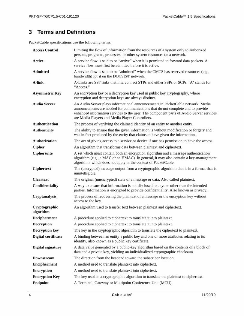
3 Terms and Definitions PacketCable specifications use the following terms:
Access Control Limiting the flow of information from the resources of a system only to authorized persons, programs, processes, or other system resources on a network.
Active A service flow is said to be “active” when it is permitted to forward data packets. A service flow must first be admitted before it is active.
Admitted A service flow is said to be “admitted” when the CMTS has reserved resources (e.g., bandwidth) for it on the DOCSIS® network.
A-link A-Links are SS7 links that interconnect STPs and either SSPs or SCPs. ‘A’ stands for “Access.”
Asymmetric Key An encryption key or a decryption key used in public key cryptography, where encryption and decryption keys are always distinct.
Audio Server An Audio Server plays informational announcements in PacketCable network. Media announcements are needed for communications that do not complete and to provide enhanced information services to the user. The component parts of Audio Server services are Media Players and Media Player Controllers.
Authentication The process of verifying the claimed identity of an entity to another entity. Authenticity The ability to ensure that the given information is without modification or forgery and
was in fact produced by the entity that claims to have given the information. Authorization The act of giving access to a service or device if one has permission to have the access. Cipher An algorithm that transforms data between plaintext and ciphertext. Ciphersuite A set which must contain both an encryption algorithm and a message authentication
algorithm (e.g., a MAC or an HMAC). In general, it may also contain a key-management algorithm, which does not apply in the context of PacketCable.
Ciphertext The (encrypted) message output from a cryptographic algorithm that is in a format that is unintelligible.
Cleartext The original (unencrypted) state of a message or data. Also called plaintext. Confidentiality A way to ensure that information is not disclosed to anyone other than the intended
parties. Information is encrypted to provide confidentiality. Also known as privacy. Cryptanalysis The process of recovering the plaintext of a message or the encryption key without
access to the key. Cryptographic algorithm
An algorithm used to transfer text between plaintext and ciphertext.
Decipherment A procedure applied to ciphertext to translate it into plaintext. Decryption A procedure applied to ciphertext to translate it into plaintext. Decryption key The key in the cryptographic algorithm to translate the ciphertext to plaintext. Digital certificate A binding between an entity’s public key and one or more attributes relating to its
identity, also known as a public key certificate. Digital signature A data value generated by a public-key algorithm based on the contents of a block of
data and a private key, yielding an individualized cryptographic checksum. Downstream The direction from the headend toward the subscriber location. Encipherment A method used to translate plaintext into ciphertext. Encryption A method used to translate plaintext into ciphertext. Encryption Key The key used in a cryptographic algorithm to translate the plaintext to ciphertext. Endpoint A Terminal, Gateway or Multipoint Conference Unit (MCU).
PSTN Gateway Call Signaling Protocol Specification PKT-SP-TGCP1.5-C01-191120
11/20/19 CableLabs 5
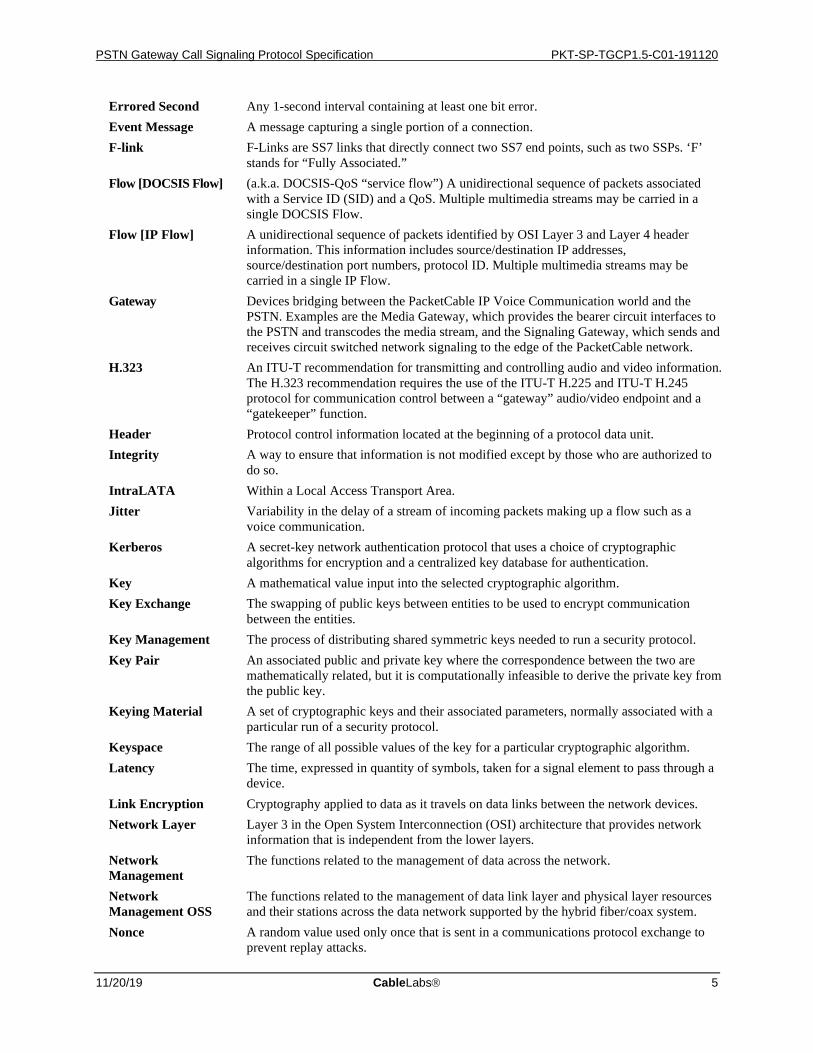
Errored Second Any 1-second interval containing at least one bit error. Event Message A message capturing a single portion of a connection. F-link F-Links are SS7 links that directly connect two SS7 end points, such as two SSPs. ‘F’
stands for “Fully Associated.” Flow [DOCSIS Flow] (a.k.a. DOCSIS-QoS “service flow”) A unidirectional sequence of packets associated
with a Service ID (SID) and a QoS. Multiple multimedia streams may be carried in a single DOCSIS Flow.
Flow [IP Flow] A unidirectional sequence of packets identified by OSI Layer 3 and Layer 4 header information. This information includes source/destination IP addresses, source/destination port numbers, protocol ID. Multiple multimedia streams may be carried in a single IP Flow.
Gateway Devices bridging between the PacketCable IP Voice Communication world and the PSTN. Examples are the Media Gateway, which provides the bearer circuit interfaces to the PSTN and transcodes the media stream, and the Signaling Gateway, which sends and receives circuit switched network signaling to the edge of the PacketCable network.
H.323 An ITU-T recommendation for transmitting and controlling audio and video information. The H.323 recommendation requires the use of the ITU-T H.225 and ITU-T H.245 protocol for communication control between a “gateway” audio/video endpoint and a “gatekeeper” function.
Header Protocol control information located at the beginning of a protocol data unit. Integrity A way to ensure that information is not modified except by those who are authorized to
do so. IntraLATA Within a Local Access Transport Area. Jitter Variability in the delay of a stream of incoming packets making up a flow such as a
voice communication. Kerberos A secret-key network authentication protocol that uses a choice of cryptographic
algorithms for encryption and a centralized key database for authentication. Key A mathematical value input into the selected cryptographic algorithm. Key Exchange The swapping of public keys between entities to be used to encrypt communication
between the entities. Key Management The process of distributing shared symmetric keys needed to run a security protocol. Key Pair An associated public and private key where the correspondence between the two are
mathematically related, but it is computationally infeasible to derive the private key from the public key.
Keying Material A set of cryptographic keys and their associated parameters, normally associated with a particular run of a security protocol.
Keyspace The range of all possible values of the key for a particular cryptographic algorithm. Latency The time, expressed in quantity of symbols, taken for a signal element to pass through a
device. Link Encryption Cryptography applied to data as it travels on data links between the network devices. Network Layer Layer 3 in the Open System Interconnection (OSI) architecture that provides network
information that is independent from the lower layers. Network Management
The functions related to the management of data across the network.
Network Management OSS
The functions related to the management of data link layer and physical layer resources and their stations across the data network supported by the hybrid fiber/coax system.
Nonce A random value used only once that is sent in a communications protocol exchange to prevent replay attacks.
PKT-SP-TGCP1.5-C01-191120 PacketCable™ 1.5 Specifications
6 CableLabs 11/20/19
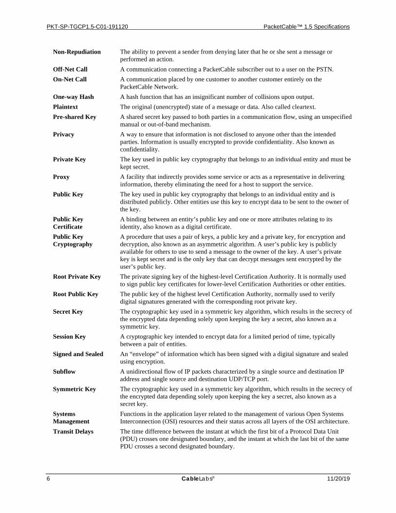
Non-Repudiation The ability to prevent a sender from denying later that he or she sent a message or performed an action.
Off-Net Call A communication connecting a PacketCable subscriber out to a user on the PSTN. On-Net Call A communication placed by one customer to another customer entirely on the
PacketCable Network. One-way Hash A hash function that has an insignificant number of collisions upon output. Plaintext The original (unencrypted) state of a message or data. Also called cleartext. Pre-shared Key A shared secret key passed to both parties in a communication flow, using an unspecified
manual or out-of-band mechanism. Privacy A way to ensure that information is not disclosed to anyone other than the intended
parties. Information is usually encrypted to provide confidentiality. Also known as confidentiality.
Private Key The key used in public key cryptography that belongs to an individual entity and must be kept secret.
Proxy A facility that indirectly provides some service or acts as a representative in delivering information, thereby eliminating the need for a host to support the service.
Public Key The key used in public key cryptography that belongs to an individual entity and is distributed publicly. Other entities use this key to encrypt data to be sent to the owner of the key.
Public Key Certificate
A binding between an entity’s public key and one or more attributes relating to its identity, also known as a digital certificate.
Public Key Cryptography
A procedure that uses a pair of keys, a public key and a private key, for encryption and decryption, also known as an asymmetric algorithm. A user’s public key is publicly available for others to use to send a message to the owner of the key. A user’s private key is kept secret and is the only key that can decrypt messages sent encrypted by the user’s public key.
Root Private Key The private signing key of the highest-level Certification Authority. It is normally used to sign public key certificates for lower-level Certification Authorities or other entities.
Root Public Key The public key of the highest level Certification Authority, normally used to verify digital signatures generated with the corresponding root private key.
Secret Key The cryptographic key used in a symmetric key algorithm, which results in the secrecy of the encrypted data depending solely upon keeping the key a secret, also known as a symmetric key.
Session Key A cryptographic key intended to encrypt data for a limited period of time, typically between a pair of entities.
Signed and Sealed An “envelope” of information which has been signed with a digital signature and sealed using encryption.
Subflow A unidirectional flow of IP packets characterized by a single source and destination IP address and single source and destination UDP/TCP port.
Symmetric Key The cryptographic key used in a symmetric key algorithm, which results in the secrecy of the encrypted data depending solely upon keeping the key a secret, also known as a secret key.
Systems Management
Functions in the application layer related to the management of various Open Systems Interconnection (OSI) resources and their status across all layers of the OSI architecture.
Transit Delays The time difference between the instant at which the first bit of a Protocol Data Unit (PDU) crosses one designated boundary, and the instant at which the last bit of the same PDU crosses a second designated boundary.

PSTN Gateway Call Signaling Protocol Specification PKT-SP-TGCP1.5-C01-191120
11/20/19 CableLabs 7
Trunk An analog or digital connection from a circuit switch that carries user media content and may carry voice signaling (MF, R2, etc.).
Tunnel Mode An IPsec (ESP or AH) mode that is applied to an IP tunnel, where an outer IP packet header (of an intermediate destination) is added on top of the original, inner IP header. In this case, the ESP or AH transform treats the inner IP header as if it were part of the packet payload. When the packet reaches the intermediate destination, the tunnel terminates, and both the outer IP packet header and the IPsec ESP or AH transform are taken out.
Upstream The direction from the subscriber location toward the headend. X.509 certificate A public key certificate specification developed as part of the ITU-T X.500 standards
directory.
PKT-SP-TGCP1.5-C01-191120 PacketCable™ 1.5 Specifications
8 CableLabs 11/20/19
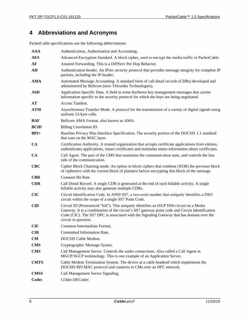
4 Abbreviations and Acronyms PacketCable specifications use the following abbreviations:
AAA Authentication, Authorization and Accounting. AES Advanced Encryption Standard. A block cipher, used to encrypt the media traffic in PacketCable. AF Assured Forwarding. This is a DiffServ Per Hop Behavior. AH Authentication header. An IPsec security protocol that provides message integrity for complete IP
packets, including the IP header. AMA Automated Message Accounting. A standard form of call detail records (CDRs) developed and
administered by Bellcore (now Telcordia Technologies). ASD Application-Specific Data. A field in some Kerberos key management messages that carries
information specific to the security protocol for which the keys are being negotiated. AT Access Tandem. ATM Asynchronous Transfer Mode. A protocol for the transmission of a variety of digital signals using
uniform 53-byte cells. BAF Bellcore AMA Format, also known as AMA. BCID Billing Correlation ID. BPI+ Baseline Privacy Plus Interface Specification. The security portion of the DOCSIS 1.1 standard
that runs on the MAC layer. CA Certification Authority. A trusted organization that accepts certificate applications from entities,
authenticates applications, issues certificates and maintains status information about certificates. CA Call Agent. The part of the CMS that maintains the communication state, and controls the line
side of the communication. CBC Cipher Block Chaining mode. An option in block ciphers that combine (XOR) the previous block
of ciphertext with the current block of plaintext before encrypting that block of the message. CBR Constant Bit Rate. CDR Call Detail Record. A single CDR is generated at the end of each billable activity. A single
billable activity may also generate multiple CDRs. CIC Circuit Identification Code. In ANSI SS7, a two-octet number that uniquely identifies a DSO
circuit within the scope of a single SS7 Point Code. CID Circuit ID (Pronounced “kid”). This uniquely identifies an ISUP DS0 circuit on a Media
Gateway. It is a combination of the circuit’s SS7 gateway point code and Circuit Identification Code (CIC). The SS7 DPC is associated with the Signaling Gateway that has domain over the circuit in question.
CIF Common Intermediate Format. CIR Committed Information Rate. CM DOCSIS Cable Modem. CMS Cryptographic Message Syntax. CMS Call Management Server. Controls the audio connections. Also called a Call Agent in
MGCP/SGCP terminology. This is one example of an Application Server. CMTS Cable Modem Termination System. The device at a cable headend which implements the
DOCSIS RFI MAC protocol and connects to CMs over an HFC network. CMSS Call Management Server Signaling. Codec COder-DECoder.

PSTN Gateway Call Signaling Protocol Specification PKT-SP-TGCP1.5-C01-191120
11/20/19 CableLabs 9
COPS Common Open Policy Service protocol. Currently an internet draft, which describes a client/server model for supporting policy control over QoS Signaling Protocols and provisioned QoS resource management.
CoS Class of Service. The type 4 tuple of a DOCSIS configuration file. CRCX Create Connection. CSR Customer Service Representative. DA Directory Assistance. DE Default. This is a DiffServ Per Hop Behavior. DES Data Encryption Standard. DF Delivery Function. DHCP Dynamic Host Configuration Protocol. DHCP-D DHCP Default. Network Provider DHCP Server. DNS Domain Name Service. DOCSIS® Data-Over-Cable Service Interface Specifications. DPC Destination Point Code. In ANSI SS7, a 3-octet number which uniquely identifies an SS7
Signaling Point, either an SSP, STP, or SCP. DQoS Dynamic Quality-of-Service. Assigned on the fly for each communication depending on the QoS
requested. DSA Dynamic Service Add. DSC Dynamic Service Change. DSCP DiffServ Code Point. A field in every IP packet that identifies the DiffServ Per Hop Behavior. In
IP version 4, the TOS byte is redefined to be the DSCP. In IP version 6, the Traffic Class octet is used as the DSCP.
DTMF Dual-tone Multi Frequency (tones). EF Expedited Forwarding. A DiffServ Per Hop Behavior. E-MTA Embedded MTA. A single node that contains both an MTA and a cable modem. EO End Office. ESP IPsec Encapsulating Security Payload. Protocol that provides both IP packet encryption and
optional message integrity, not covering the IP packet header. ETSI European Telecommunications Standards Institute. F-link F-Links are SS7 links that directly connect two SS7 end points, such as two SSPs. ‘F’ stands for
“Fully Associated.” FEID Financial Entity ID. FGD Feature Group D signaling. FQDN Fully Qualified Domain Name. Refer to IETF RFC 2821 for details. GC Gate Controller. GTT Global Title Translation. HFC Hybrid Fiber/Coaxial. An HFC system is a broadband bi-directional shared media transmission
system using fiber trunks between the headend and the fiber nodes, and coaxial distribution from the fiber nodes to the customer locations.
HMAC Hashed Message Authentication Code. A message authentication algorithm, based on either SHA-1 or MD5 hash and defined in IETF RFC 2104.
HTTP Hypertext Transfer Protocol. Refer to IETF RFC 1945 and RFC 2068. IANA Internet Assigned Numbered Authority. See www.ietf.org for details.
PKT-SP-TGCP1.5-C01-191120 PacketCable™ 1.5 Specifications
10 CableLabs 11/20/19
IC Inter-exchange Carrier. IETF Internet Engineering Task Force. A body responsible, among other things, for developing
standards used on the Internet. See www.ietf.org for details. IKE Internet Key Exchange. A key-management mechanism used to negotiate and derive keys for SAs
in IPsec. IKE– A notation defined to refer to the use of IKE with pre-shared keys for authentication. IKE+ A notation defined to refer to the use of IKE with X.509 certificates for authentication. IP Internet Protocol. An Internet network-layer protocol. IPsec Internet Protocol Security. A collection of Internet standards for protecting IP packets with
encryption and authentication. ISDN Integrated Services Digital Network. ISTP Internet Signaling Transport Protocol. ISUP ISDN User Part. A protocol within the SS7 suite of protocols that is used for call signaling within
an SS7 network. ITU International Telecommunication Union. ITU-T International Telecommunication Union–Telecommunication Standardization Sector. IVR Interactive Voice Response system. KDC Key Distribution Center. LATA Local Access and Transport Area. LD Long Distance. LIDB Line Information Database. Contains customer information required for real-time access such as
calling card personal identification numbers (PINs) for real-time validation. LLC Logical Link Control. The Ethernet Packet header and optional 802.1P tag which may encapsulate
an IP packet. A sublayer of the Data Link Layer. LNP Local Number Portability. Allows a customer to retain the same number when switching from one
local service provider to another. LSSGR LATA Switching Systems Generic Requirements. MAC Message Authentication Code. A fixed-length data item that is sent together with a message to
ensure integrity, also known as a MIC. MAC Media Access Control. It is a sublayer of the Data Link Layer. It normally runs directly over the
physical layer. MC Multipoint Controller. MCU Multipoint Conferencing Unit. MD5 Message Digest 5. A one-way hash algorithm that maps variable length plaintext into fixed-length
(16 byte) ciphertext. MDCP Media Device Control Protocol. A media gateway control specification submitted to IETF by
Lucent. Now called SCTP. MDCX Modify Connection. MDU Multi-Dwelling Unit. Multiple units within the same physical building. The term is usually
associated with high-rise buildings. MEGACO Media Gateway Control IETF working group. See www.ietf.org for details. MF Multi-Frequency. MG Media Gateway. Provides the bearer circuit interfaces to the PSTN and transcodes the media
stream.
PSTN Gateway Call Signaling Protocol Specification PKT-SP-TGCP1.5-C01-191120
11/20/19 CableLabs 11
MGC Media Gateway Controller. The overall controller function of the PSTN gateway. Receives, controls and mediates call-signaling information between the PacketCable and PSTN.
MGCP Media Gateway Control Protocol. Protocol follow-on to SGCP. Refer to IETF 2705. MIB Management Information Base. MIC Message Integrity Code. A fixed-length data item that is sent together with a message to ensure
integrity, also known as a Message Authentication Code (MAC). MMC Multi-Point Mixing Controller. A conferencing device for mixing media streams of multiple
connections. MSB Most Significant Bit. MSO Multi-System Operator. A cable company that operates many headend locations in several cities. MSU Message Signal Unit. MTA Multimedia Terminal Adapter. Contains the interface to a physical voice device, a network
interface, CODECs, and all signaling and encapsulation functions required for VoIP transport, class features signaling, and QoS signaling.
MTP The Message Transfer Part. A set of two protocols (MTP 2, MTP 3) within the SS7 suite of protocols that are used to implement physical, data link, and network-level transport facilities within an SS7 network.
MWD Maximum Waiting Delay. NANP North American Numbering Plan. NANPNAT North American Numbering Plan Network Address Translation. NAT Network Layer
Network Address Translation. Layer 3 in the Open System Interconnection (OSI) architecture. This layer provides services to establish a path between open systems.
NCS Network Call Signaling. NPA-NXX Numbering Plan Area (more commonly known as area code) NXX (sometimes called exchange)
represents the next three numbers of a traditional phone number. The N can be any number from 2-9 and the Xs can be any number. The combination of a phone number’s NPA-NXX will usually indicate the physical location of the call device. The exceptions include toll-free numbers and ported number (see LNP).
NTP Network Time Protocol. An internet standard used for synchronizing clocks of elements distributed on an IP network.
NTSC National Television Standards Committee. Defines the analog color television broadcast standard used today in North America.
OID Object Identification. OSP Operator Service Provider. OSS Operations Systems Support. The back-office software used for configuration, performance, fault,
accounting, and security management. OSS-D OSS Default. Network Provider Provisioning Server. PAL Phase Alternate Line. The European color television format that evolved from the American
NTSC standard. PCES PacketCable Electronic Surveillance. PCM Pulse Code Modulation. A commonly employed algorithm to digitize an analog signal (such as a
human voice) into a digital bit stream using simple analog-to-digital conversion techniques. PDU Protocol Data Unit. PHS Payload Header Suppression. A DOCSIS technique for compressing the Ethernet, IP, and UDP
headers of RTP packets.

PKT-SP-TGCP1.5-C01-191120 PacketCable™ 1.5 Specifications
12 CableLabs 11/20/19
PKCROSS Public-Key Cryptography for Cross-Realm Authentication. Utilizes PKINIT for establishing the inter-realm keys and associated inter-realm policies to be applied in issuing cross-realm service tickets between realms and domains in support of Intradomain and Interdomain CMS-to-CMS signaling (CMSS).
PKCS Public-Key Cryptography Standards. Published by RSA Data Security Inc. These Standards describe how to use public key cryptography in a reliable, secure and interoperable way.
PKI Public-Key Infrastructure. A process for issuing public key certificates, which includes standards, Certification Authorities, communication between authorities and protocols for managing certification processes.
PKINIT Public-Key Cryptography for Initial Authentication. The extension to the Kerberos protocol that provides a method for using public-key cryptography during initial authentication.
PSC Payload Service Class Table, a MIB table that maps RTP payload Type to a Service Class Name. PSFR Provisioned Service Flow Reference. An SFR that appears in the DOCSIS configuration file. PSTN Public Switched Telephone Network. QCIF Quarter Common Intermediate Format. QoS Quality of Service. Guarantees network bandwidth and availability for applications. RADIUS Remote Authentication Dial-In User Service. An internet protocol (IETF RFC 2865 and RFC
2866) originally designed for allowing users dial-in access to the internet through remote servers. Its flexible design has allowed it to be extended well beyond its original intended use.
RAS Registration, Admissions and Status. RAS Channel is an unreliable channel used to convey the RAS messages and bandwidth changes between two H.323 entities.
RC4 Rivest Cipher 4. A variable length stream cipher. Optionally used to encrypt the media traffic in PacketCable.
RFC Request for Comments. Technical policy documents approved by the IETF which are available on the World Wide Web at http://www.ietf.cnri.reston.va.us/rfc.html.
RFI The DOCSIS Radio Frequency Interface specification. RJ-11 Registered Jack-11. A standard 4-pin modular connector commonly used in the United States for
connecting a phone unit into a wall jack. RKS Record Keeping Server. The device, which collects and correlates the various Event Messages. RSA A public-key, or asymmetric, cryptographic algorithm used to provide authentication and
encryption services. RSA stands for the three inventors of the algorithm; Rivest, Shamir, Adleman.
RSA Key Pair A public/private key pair created for use with the RSA cryptographic algorithm. RSVP Resource Reservation Protocol. RTCP Real-Time Control Protocol. RTO Retransmission Timeout. RTP Real-time Transport Protocol. A protocol for encapsulating encoded voice and video streams.
Refer to IETF RFC 1889. SA Security Association. A one-way relationship between sender and receiver offering security
services on the communication flow. SAID Security Association Identifier. Uniquely identifies SAs in the DOCSIS Baseline Privacy Plus
Interface (BPI+) security protocol. SCCP Signaling Connection Control Part. A protocol within the SS7 suite of protocols that provides two
functions in addition to those provided within MTP. The first function is the ability to address applications within a signaling point. The second function is Global Title Translation.
SCP Service Control Point. A Signaling Point within the SS7 network, identifiable by a Destination Point Code that provides database services to the network.
PSTN Gateway Call Signaling Protocol Specification PKT-SP-TGCP1.5-C01-191120
11/20/19 CableLabs 13
SCTP Stream Control Transmission Protocol. SDP Session Description Protocol. SDU Service Data Unit. Information delivered as a unit between peer service access points. SF Service Flow. A unidirectional flow of packets on the RF interface of a DOCSIS system. SFID Service Flow ID. A 32-bit integer assigned by the CMTS to each DOCSIS Service Flow defined
within a DOCSIS RF MAC domain. SFIDs are considered to be in either the upstream direction (USFID) or downstream direction (DSFID). Upstream Service Flow IDs and Downstream Service Flow IDs are allocated from the same SFID number space.
SFR Service Flow Reference. A 16-bit message element used within the DOCSIS TLV parameters of Configuration Files and Dynamic Service messages to temporarily identify a defined Service Flow. The CMTS assigns a permanent SFID to each SFR of a message.
SG Signaling Gateway. An SG is a signaling agent that receives/sends SCN native signaling at the edge of the IP network. In particular, the SS7 SG function translates variants ISUP and TCAP in an SS7-Internet Gateway to a common version of ISUP and TCAP.
SGCP Simple Gateway Control Protocol. Earlier draft of MGCP. SHA – 1 Secure Hash Algorithm 1. A one-way hash algorithm. SID Service ID. A 14-bit number assigned by a CMTS to identify an upstream virtual circuit. Each
SID separately requests and is granted the right to use upstream bandwidth. SIP Session Initiation Protocol. An application-layer control (signaling) protocol for creating,
modifying, and terminating sessions with one or more participants. SIP+ Session Initiation Protocol Plus. An extension to SIP. S-MTA Standalone MTA. A single node that contains an MTA and a non-DOCSIS MAC (e.g., ethernet). SNMP Simple Network Management Protocol. SOHO Small Office/Home Office. SS7 Signaling System number 7. An architecture and set of protocols for performing out-of-band call
signaling with a telephone network. SSP Service Switching Point. SSPs are points within the SS7 network that terminate SS7 signaling
links and also originate, terminate, or tandem switch calls. STP Signal Transfer Point. A node within an SS7 network that routes signaling messages based on
their destination address. This is essentially a packet switch for SS7. It may also perform additional routing services such as Global Title Translation.
TCAP Transaction Capabilities Application Protocol. A protocol within the SS7 stack that is used for performing remote database transactions with a Signaling Control Point.
TCP Transmission Control Protocol. TD Timeout for Disconnect. TFTP Trivial File Transfer Protocol. TFTP-D Default – Trivial File Transfer Protocol. TGS Ticket Granting Server. A sub-system of the KDC used to grant Kerberos tickets. TGW Telephony Gateway. TIPHON Telecommunications and Internet Protocol Harmonization Over Network. TLV Type-Length-Value. A tuple within a DOCSIS configuration file. TN Telephone Number. ToD Time-of-Day Server. TOS Type of Service. An 8-bit field of every IP version 4 packet. In a DiffServ domain, the TOS byte
is treated as the DiffServ Code Point, or DSCP.

PKT-SP-TGCP1.5-C01-191120 PacketCable™ 1.5 Specifications
14 CableLabs 11/20/19
TSG Trunk Subgroup. UDP User Datagram Protocol. A connectionless protocol built upon Internet Protocol (IP). VAD Voice Activity Detection. VBR Variable Bit Rate. VoIP Voice-over-IP.
PSTN Gateway Call Signaling Protocol Specification PKT-SP-TGCP1.5-C01-191120
11/20/19 CableLabs 15
5 Abstract This document describes a PacketCable™ profile of an application programming interface called a Media Gateway Control Interface (MGCI) and a corresponding protocol (MGCP) for controlling voice-over-IP (VoIP) PSTN Gateways from external call control elements. The MGCP assumes a call control architecture where the call control "intelligence" is outside the gateways and handled by external call control elements. The PacketCable profile as described in this document will be referred to as the PacketCable Trunking Gateway Control Protocol (TGCP).
This document is based on the PacketCable Network-Based Call Signaling (NCS) 1.5 specification [13], the Media Gateway Control Protocol (MGCP) 1.0 IETF RFC [1] (which was the result of a merge of the IETF draft of Simple Gateway Control Protocol and the IETF draft of IP Device Control (IPDC) family of protocols), and input generated by the PacketCable PSTN Gateway focus team.
This document, which defines the PacketCable TGCP Protocol, constitutes a document that is independent of MGCP in order to provide a stable reference document while meeting current time-to-market demands for such a reference. It is the intent of this document to be as closely aligned with NCS and MGCP 1.0 as possible for the PacketCable environment, in order to avoid developing multiple protocols to solve the same problem. This goal has been and continues to be pursued through cooperation with the authors of the NCS and MGCP specifications. The TGCP profile of MGCP, however, is strictly and solely defined by the contents of this document.
This TGCP profile of MGCP, which will be referred to as the PSTN Trunking Gateway Call Signaling Protocol 1.0, TGCP 1.0, the TGCP profile, or simply TGCP in this document, has been modified from the MGCP 1.0 IETF RFC [1] in the following ways:
• The TGCP protocol only aims at supporting PacketCable voice-over-IP PSTN Gateways. The TGCP protocol supports voice-over-IP PSTN Gateways as defined by PacketCable. Functionality present in the MGCP 1.0 protocol, which was superfluous to TGCP, has been removed.
• The TGCP protocol contains extensions and modifications to MGCP. PacketCable-specific requirements are addressed in TGCP. However, the MGCP architecture, and all of the MGCP constructs relevant to PSTN Gateways, have been preserved in TGCP.
• The TGCP protocol contains minor simplifications from MGCP 1.0. Where several choices were available, and not necessarily needed for a PSTN Gateway in the PacketCable environment, some simplifications have been made for trunking gateway implementations.
Although MGCP is not TGCP, and TGCP is not MGCP, the names MGCP and TGCP will be used interchangeably in this document since this document is based on MGCP. Unless otherwise stated or inferable by context, the word MGCP shall be taken to mean the TGCP profile of MGCP in this document.
TGCP is designed to meet the protocol requirements for the Media Gateway Controller to Media Gateway interface defined in the PacketCable architecture.
The document is structured in the following main sections:
• The introduction presents the basic assumptions and the relation to other PacketCable control and signaling protocols.
• The interface section presents a conceptual overview of the TGCP profile, presenting the naming conventions, the usage of the session description protocol (SDP), and the procedures that compose TGCP:
• Notification Request,
• Notify,
• Create Connection,
• Modify Connection,
• Delete Connection,
• Audit Endpoint,
PKT-SP-TGCP1.5-C01-191120 PacketCable™ 1.5 Specifications
16 CableLabs 11/20/19
• Audit Connection, and
• Restart In Progress
• Each of the commands is presented as an example API with the name of the command, the parameters it can take and return, as well as the semantics of each of these. The actual encoding of the command and its parameters is shown in the protocol description section. The section concludes with a description of how reliability and race conditions are handled.
• The protocol description section presents the actual TGCP encodings of the commands and parameters which are based on simple text formats. The transmission procedure over UDP is specified as well.
• The security section presents the security of TGCP.
• The appendices contain definitions of event packages, mode interactions, example command encodings, a complete example call flow, endpoint requirements, and compatibility information.
From time to time this document refers to the voice communications capabilities of a PacketCable network in terms of "IP Telephony." The legal/regulatory classification of IP-based voice communications provided over cable networks and otherwise, and the legal/regulatory obligations, if any, borne by providers of such voice communications, are not yet fully defined by appropriate legal and regulatory authorities. Nothing in this document is addressed to, or intended to affect, those issues. In particular, while this document uses standard terms such as "call," "call flow," "telephony," etc., it should be recalled that while a PacketCable network performs activities analogous to these PSTN functions, the manner by which it does so differs considerably from the manner in which they are performed in the PSTN by telecommunications carriers, and that these differences may be significant for legal/regulatory purposes. Moreover, while reference is made here to "IP Telephony," it should be recognized that this term embraces a number of different technologies and network architecture, each with different potential associated legal/regulatory obligations. No particular legal/regulatory consequences are assumed or implied by the use of this term.
PSTN Gateway Call Signaling Protocol Specification PKT-SP-TGCP1.5-C01-191120
11/20/19 CableLabs 17
6 Introduction This document describes the TGCP profile of an application programming interface (MGCI) and a corresponding protocol (MGCP) for controlling trunking gateways from external call control elements. A trunking gateway is a network element that provides analog, emulated analog, or digital bearer and channel-associated signaling trunk circuit access to a voice-over-IP (VoIP) network.
Trunking gateways are used for interfacing to the PSTN and as such are expected to adhere to the relevant electrical, operational, and signaling standards for the trunk type they implement. The TGCP specification is developed for CLECs, and in the first version of this specification the trunk types that will be supported are limited to the following:
• SS7 ISUP:
• Standard Bearer trunk
• MF trunks on a combined Equal Access End Office/Access Tandem (EAEO/AT):
• Operator Services trunks1
• CLEC subscriber access through a LEC Access Tandem
• Operator access to EAEO/AT for Busy Line Verification and Barge In
• E911 trunks for access to an E911 Tandem
The MGCP assumes a call control architecture where the call control "intelligence" is outside the gateways and handled by external call-control elements referred to as Media Gateway Controllers. The MGCP assumes that these call-control elements, or Media Gateway Controllers (MGCs), will synchronize with each other to send coherent commands to the gateways under their control. The MGCP defined in this document does not define a mechanism for synchronizing Media Gateway Controllers, although future PacketCable specifications may specify such mechanisms.
The MGCP assumes a connection model where the basic constructs are endpoints and connections. A gateway contains a collection of endpoints, which are sources, or sinks, of data and could be physical or virtual.
An example of a physical endpoint is a trunk circuit on a trunking gateway that terminates an ISUP bearer trunk to a switch. Another example is an embedded client or residential gateway that terminates residential POTS lines (to phones), although such devices are not addressed by this specification.
An example of a virtual endpoint is an audio source in an audio-content server. Creation of physical endpoints requires hardware installation, while creation of virtual endpoints can be accomplished by software. However, the TGCP profile of MGCP only addresses physical endpoints.
Connections are point-to-point. A point-to-point connection is an association between two endpoints with the purpose of transmitting data between these endpoints. Once this association is established for both endpoints, data transfer between these endpoints can take place. The association is established by creating the connection as two halves; one on the origination endpoint, and one on the terminating endpoint.
Media Gateway Controllers instruct the gateways to create connections between endpoints and to detect certain events, e.g., continuity test, and generate certain signals, e.g., ringback. It is strictly up to the Media Gateway Controller to specify how and when connections are made, between which endpoints they are made, as well as what events and signals are to be detected and generated on the endpoints. The gateway, thereby, becomes a simple device, without any call state, that receives general instructions from the Media Gateway Controller without any need to know about or even understand the concept of calls, call states, features, or feature interactions. When new services are introduced, customer profiles changed, etc., the changes are transparent to the gateway. The Media Gateway Controllers implement the changes and generate the appropriate new mix of instructions to the gateways for the changes made. Whenever the gateway reboots, it will come up in a clean state and simply carry out the Media Gateway Controller's instructions as they are received.
1 Operator Services are expected to be provided by or accessed through a LEC.
PKT-SP-TGCP1.5-C01-191120 PacketCable™ 1.5 Specifications
18 CableLabs 11/20/19
6.1 Relation With Other PacketCable Standards
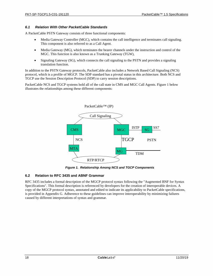
A PacketCable PSTN Gateway consists of three functional components:
• Media Gateway Controller (MGC), which contains the call intelligence and terminates call signaling. This component is also referred to as a Call Agent.
• Media Gateway (MG), which terminates the bearer channels under the instruction and control of the MGC. This function is also known as a Trunking Gateway (TGW),
• Signaling Gateway (SG), which connects the call signaling to the PSTN and provides a signaling translation function.
In addition to the PSTN Gateway protocols, PacketCable also includes a Network Based Call Signaling (NCS) protocol, which is a profile of MGCP. The SDP standard has a pivotal status in this architecture. Both NCS and TGCP use the Session Description Protocol (SDP) to carry session descriptions.
PacketCable NCS and TGCP systems hold all of the call state in CMS and MGC Call Agents. Figure 1 below illustrates the relationships among these different components:
TGCP
MTA MG
MGC CMS SG
NCS
ISTP
TDM
Call Signaling
RTP/RTCP
SS7
PacketCable™ (IP)
PSTN
Figure 1. Relationship Among NCS and TGCP Components
6.2 Relation to RFC 3435 and ABNF Grammar RFC 3435 includes a formal description of the MGCP protocol syntax following the "Augmented BNF for Syntax Specifications". This formal description is referenced by developers for the creation of interoperable devices. A copy of the MGCP protocol syntax, annotated and edited to indicate its applicability to PacketCable specifications, is provided in Appendix G. Adherence to these guidelines can improve interoperability by minimizing failures caused by different interpretations of syntax and grammar.
PSTN Gateway Call Signaling Protocol Specification PKT-SP-TGCP1.5-C01-191120
11/20/19 CableLabs 19
7 Media Gateway Control Interface (MGCI) MGCI functions provide for connection control, endpoint control, auditing, and status reporting. They each use the same system model and the same naming conventions.
7.1 Model and Naming Conventions MGCP assumes a connection model where the basic constructs are endpoints and connections. Connections are grouped in calls. One or more connections can belong to one call. Connections and calls are set up at the initiative of one or several Media Gateway Controllers. It should be recognized that in none of these cases is a "connection" established within a PacketCable network as the term "connection" is understood within the circuit-switched PSTN. The terms "call" and "connection" in this context (and throughout this document) are used for convenience of reference, not to indicate any actual technical or other similarity between the PacketCable network and the PSTN.
7.1.1 Endpoint Names Endpoint names, also known as endpoint identifiers, have two components, both of which are defined to be case insensitive here:
• the domain name of the gateway managing the endpoint,
• a local endpoint name within that gateway
Endpoint names will be of the form local-endpoint-name@domain-name
where domain-name is an absolute domain-name as defined in IETF RFC 1034/STD 0013 [16] and includes a host portion, thus an example domain-name could be
MyTrunkingGateway.cablelabs.com.
Also, domain-name may be an IPv4 address in dotted decimal form represented as a text-string and surrounded by a left and a right square bracket ("[" and "]") as in "[128.96.41.1]"—please consult [15] for details. However, use of IP addresses is generally discouraged.
Trunking gateways have one or more endpoints (e.g., one for each trunk) associated with them, and each of the endpoints is identified by a separate local endpoint name. Just like the domain-name, the local endpoint name is case insensitive. Associated with the local endpoint name is an endpoint-type, which defines the type of the endpoint, e.g., DS-0, or an analog access line. The type can be derived from the local endpoint name. The local endpoint name is a hierarchical name, where the least specific component of the name is the leftmost term, and the most specific component is the rightmost term. More formally, the local endpoint name MUST adhere to the following naming rules:
• The individual terms of the local endpoint name must be separated by a single slash ("/", ASCII 2F hex).
• The individual terms are ASCII character strings composed of letters, digits or other printable characters, with the exception of characters used as delimiters in endpoint-names ("/", "@"), characters used for wildcarding ("*", "$"), and white space characters.
• Wild carding is represented either by an asterisk ("*") or a dollar sign ("$") for the terms of the naming path which are to be wild-carded. Thus, if the full local endpoint name looks like
term1/term2/term3
and one of the terms of the local endpoint name is wild-carded, then the local endpoint name looks like this: term1/term2/* if term3 is wild-carded. term1/*/* if term2 and term3 are wild-carded.
In each example, a dollar sign could have appeared instead of the asterisk.
• Wild-carding is only allowed from the right, thus if a term is wild-carded, then all terms to the right of that term must be wild-carded as well.
PKT-SP-TGCP1.5-C01-191120 PacketCable™ 1.5 Specifications
20 CableLabs 11/20/19
• In cases where mixed dollar sign and asterisk wild-cards are used, dollar-signs are only allowed from the right, thus if a term had a dollar sign wild-card, all terms to the right of that term must also contain dollar sign wild-cards.
• A term represented by an asterisk is to be interpreted as "use all values of this term known within the scope of the trunking gateway in question". Unless specified otherwise, this refers to all endpoints configured for service, regardless of their actual service state, i.e., in-service or out-of-service.
• A term represented by a dollar sign is to be interpreted as "use any one value of this term known within the scope of the trunking gateway in question". Unless specified otherwise, this only refers to endpoints that are in-service.
• Each endpoint-type may specify additional detail in the naming rules for that endpoint-type, however such rules must not be in conflict with the above.
It should be noted that different endpoint-types or even different sub-terms, e.g., "lines", within the same endpoint-type will result in two different local endpoint names. Consequently, each "line" will be treated as a separate endpoint. Note that since the domain name portion is part of the endpoint identifier, different forms or different values referring to the same entity are not freely interchangeable. Following a restart, the most recently supplied form and value MUST always be used.
7.1.1.1 Trunking Gateway Endpoint Names
Endpoints in trunking gateways MUST support the additional naming conventions specified in this section.
Trunking gateways will support the following basic endpoint-type: ds A DS-0 trunk
The basic endpoint type is expected to be provisioned with additional information about the type of signaling supported on the trunk circuit and the switching system role it provides. The current version of the TGCP specification considers Media Gateways that implement one or more of the following trunk types:
• SS7 ISUP:
• Standard Bearer trunk - This trunk type may implement a variety of trunk types – the Media Gateway Controller will implement the necessary logic.
• MF trunks on a combined Equal Access End Office/Access Tandem (EAEO/AT):
• Operator Services trunks2
• CLEC subscriber access through a LEC Access Tandem. One way outgoing MF Operator Services Signaling Protocol will be implemented for this (see [7], Operator Services Signaling). Both Feature Group C and Feature Group D Operator Services Signaling will be supported.
• Operator access to EAEO/AT for Busy Line Verification and Barge In. One-way incoming MF Terminating Protocol will be implemented for this (see [7], Terminating Protocol).
• E911 trunks for access to an E911 Tandem. One way outgoing MF Operator Services Signaling Protocol will be implemented for this (see [7], Operator Services Signaling).
7.1.1.1.1 Trunk Circuit Endpoints In addition to the naming conventions specified above, local endpoint names for PSTN trunking gateway endpoints of type "ds" MUST adhere to the following:
• Local endpoint names will consist of a series of terms each separated by a slash ("/") that describe the physical hierarchy within the gateway:
ds/<unit-type1>-<unit #>/<unit-type2>-<unit #>/…/<channel #>
2 Operator Services are expected to be provided by or accessed through a LEC.

PSTN Gateway Call Signaling Protocol Specification PKT-SP-TGCP1.5-C01-191120
11/20/19 CableLabs 21
• The first term (ds) identifies the endpoint naming scheme used and the basic endpoint type.
• The last term is a decimal number that indicates the channel number3 at the lowest level of the hierarchy.
• Intermediate terms between the first term (ds) and last term (channel number) represent intermediate levels of the hierarchy and consist of <unit-type> and <unit #> separated by a hyphen ("-") where:
• the <unit-type> identifies the particular hierarchy level. Values of <unit-type> presently defined are: "s", "su", "oc3", "ds3", "e3", "ds2", "e2", "ds1", "e1" where "s" indicates a slot number and "su" indicates a sub-unit within a slot. Other values representing physical hierarchy levels that have not been included in this list, but which follow the same basic naming rules will also be allowed.
• the <unit #> is a decimal number which is used to reference a particular instance of a <unit-type> at that level of the hierarchy.
• The number of levels and naming of those levels is based on the physical hierarchy within the media gateway, as illustrated by the following examples:
• A Media Gateway that has some number of DS1 interfaces: ds/ds1-#/#
• A Media Gateway that has some number of OC3 interfaces, that contain channelized DS3 and DS1 hierarchies:
ds/oc3-#/ds3-#/ds1-#/#
• A Media Gateway that contains some number of slots with each slot having some number of DS3 interfaces:
ds/s-#/ds3-#/ds1-#/#
• Some endpoints may not contain all possible levels of a hierarchy, however all levels supported by a given endpoint are contained in the endpoint naming scheme. For example, a DS3 without DS1 framing could be represented by the following naming scheme: ds/s-#/ds3-#/#
However, a DS3 with DS1 framing could not be represented by that naming scheme.
• Wildcard naming follows the conventions stated in Section 7.1.1 with the asterisk character ("*") referring to "all", and the dollar character ("$") referring to "any". A range "[N-M]" wildcarding convention representing a "range" of channels from channel N to channel M inclusive is supported as well.
• It should be noted that the use of the "all" wildcard for the first (ds) term refers to all endpoint-types in the media gateway regardless of their type. Use of this feature is generally expected to be for administrative purposes, e.g., auditing or restart.
• A local endpoint name may be under-specified by supplying some smaller than normal number of terms starting from the left-hand side of the endpoint name. In that case, missing terms to the right of the last term specified are assumed to be the wildcard character "*", referring to "all of", unless the terms specified contain the "any of" wildcard character, in which case missing terms to the right of the last term specified are assumed to be the "any of" wildcard character.
• Wherever use of the "all" wildcard is permitted, the range of channels "[N-M]" wildcard may be used in the last term (i.e., <channel-#>) of the local endpoint name instead. The "range" wildcard will then refer to all of the channels from N to M. The rules and restrictions that apply to the use of the "all" wildcard also apply to the use of the "range" wildcard.
• The following examples illustrate the use of wild-carding:
3 Please note the use of the term "channel" as opposed to "timeslot".
PKT-SP-TGCP1.5-C01-191120 PacketCable™ 1.5 Specifications
22 CableLabs 11/20/19
ds/ds1-3/* All channels on ds1 number 3 on the media gateway in question.
ds/ds1-3/$ Any channel on ds1 number 3 on the media gateway in question.
ds/* All trunk-circuit endpoints on the media gateway in question.
* All endpoints (regardless of endpoint-type) on the media gateway in question.
ds/ds1-3/[1-24] Channels 1 to 24 on ds1 number 3 on the media gateway in question.
The above define the canonical names for endpoints in a trunking gateway. It is expected that aliasing may be supported in a future version of this document, e.g., to support bonding of multiple DS-0 trunks for video calls, e.g., on the form "ds/ds1-1/H0-1".
7.1.2 Call Names
Calls are identified by unique identifiers, independent of the underlying platforms or agents. Call identifiers are hexadecimal strings, which are created by the Media Gateway Controller. Call identifiers with a maximum length of 32 characters MUST be supported.
At a minimum, call identifiers MUST be unique within the collection of Media Gateway Controllers that control the same gateways. However, the coordination of these call identifiers between Media Gateway Controllers is outside the scope of this document. When a Media Gateway Controller builds several connections that pertain to the same call, either on the same gateway or in different gateways, these connections all will be linked to the same call through the call identifier. This identifier then can be used by accounting or management procedures, which are outside the scope of MGCP.
7.1.3 Connection Names
Connection identifiers are created by the gateway when it is requested to create a connection. They identify the connection within the context of an endpoint. Connection identifiers are treated in MGCP as hexadecimal strings. The gateway MUST ensure that a proper waiting period, at least three minutes, elapses between the end of a connection that used this identifier and its use in a new connection for the same endpoint. Connection Names with a maximum length of 32 characters MUST be supported.
7.1.4 Names of Media Gateway Controllers and Other Entities
The Media Gateway Control Protocol has been designed for enhanced network reliability to allow implementation of redundant Media Gateway Controllers. This means that there is no fixed binding between entities and hardware platforms or network interfaces.
Media Gateway Controller names consist of two parts, similar to endpoint names. The local portion of the name does not exhibit any internal structure. An example Media Gateway Controller name is: [email protected]
Reliability is provided by the following precautions:
Entities such as trunking gateways or Media Gateway Controllers are identified by their domain name, not their network addresses. Several addresses can be associated with a domain name. If a command cannot be forwarded to one of the network addresses, implementations MUST retry the transmission using another address.
Entities may move to another platform. The association between a logical name (domain name) and the actual platform are kept in the Domain Name Service (DNS). Media Gateway Controllers and gateways MUST keep track of the record's time-to-live read from the DNS. They MUST query the DNS to refresh the information if the time-to-live has expired.
In addition to the indirection provided by the use of domain names and the DNS, the concept of "notified entity" is central to reliability and failover in MGCP. The "notified entity" for an endpoint is the Media Gateway Controller currently controlling that endpoint. At any point in time, an endpoint has one, and only one, "notified entity" associated with it, and when the endpoint needs to send a command to the Media Gateway Controller, it MUST send
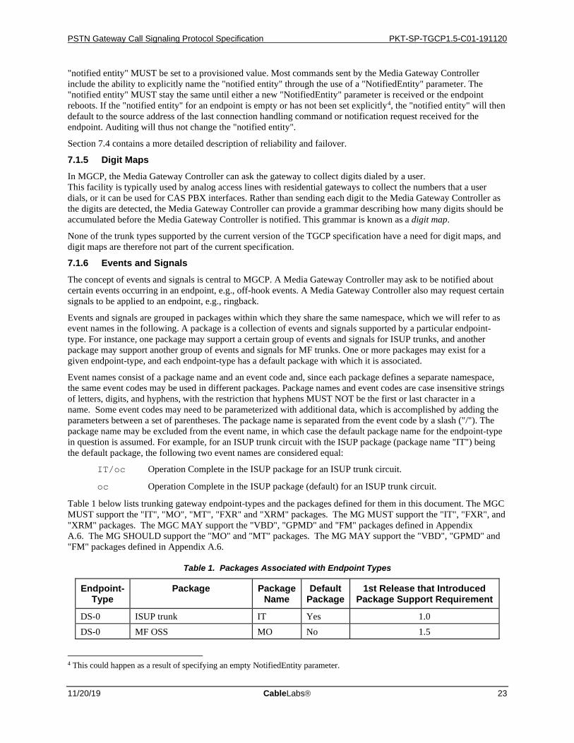
PSTN Gateway Call Signaling Protocol Specification PKT-SP-TGCP1.5-C01-191120
11/20/19 CableLabs 23
"notified entity" MUST be set to a provisioned value. Most commands sent by the Media Gateway Controller include the ability to explicitly name the "notified entity" through the use of a "NotifiedEntity" parameter. The "notified entity" MUST stay the same until either a new "NotifiedEntity" parameter is received or the endpoint reboots. If the "notified entity" for an endpoint is empty or has not been set explicitly4, the "notified entity" will then default to the source address of the last connection handling command or notification request received for the endpoint. Auditing will thus not change the "notified entity".
Section 7.4 contains a more detailed description of reliability and failover.
7.1.5 Digit Maps In MGCP, the Media Gateway Controller can ask the gateway to collect digits dialed by a user. This facility is typically used by analog access lines with residential gateways to collect the numbers that a user dials, or it can be used for CAS PBX interfaces. Rather than sending each digit to the Media Gateway Controller as the digits are detected, the Media Gateway Controller can provide a grammar describing how many digits should be accumulated before the Media Gateway Controller is notified. This grammar is known as a digit map.
None of the trunk types supported by the current version of the TGCP specification have a need for digit maps, and digit maps are therefore not part of the current specification.
7.1.6 Events and Signals The concept of events and signals is central to MGCP. A Media Gateway Controller may ask to be notified about certain events occurring in an endpoint, e.g., off-hook events. A Media Gateway Controller also may request certain signals to be applied to an endpoint, e.g., ringback.
Events and signals are grouped in packages within which they share the same namespace, which we will refer to as event names in the following. A package is a collection of events and signals supported by a particular endpoint-type. For instance, one package may support a certain group of events and signals for ISUP trunks, and another package may support another group of events and signals for MF trunks. One or more packages may exist for a given endpoint-type, and each endpoint-type has a default package with which it is associated.
Event names consist of a package name and an event code and, since each package defines a separate namespace, the same event codes may be used in different packages. Package names and event codes are case insensitive strings of letters, digits, and hyphens, with the restriction that hyphens MUST NOT be the first or last character in a name. Some event codes may need to be parameterized with additional data, which is accomplished by adding the parameters between a set of parentheses. The package name is separated from the event code by a slash ("/"). The package name may be excluded from the event name, in which case the default package name for the endpoint-type in question is assumed. For example, for an ISUP trunk circuit with the ISUP package (package name "IT") being the default package, the following two event names are considered equal:
IT/oc Operation Complete in the ISUP package for an ISUP trunk circuit.
oc Operation Complete in the ISUP package (default) for an ISUP trunk circuit.
Table 1 below lists trunking gateway endpoint-types and the packages defined for them in this document. The MGC MUST support the "IT", "MO", "MT", "FXR" and "XRM" packages. The MG MUST support the "IT", "FXR", and "XRM" packages. The MGC MAY support the "VBD", "GPMD" and "FM" packages defined in Appendix A.6. The MG SHOULD support the "MO" and "MT" packages. The MG MAY support the "VBD", "GPMD" and "FM" packages defined in Appendix A.6.
Table 1. Packages Associated with Endpoint Types
Endpoint-Type
Package Package Name
Default Package
1st Release that Introduced Package Support Requirement
DS-0 ISUP trunk IT Yes 1.0 DS-0 MF OSS MO No 1.5
4 This could happen as a result of specifying an empty NotifiedEntity parameter.
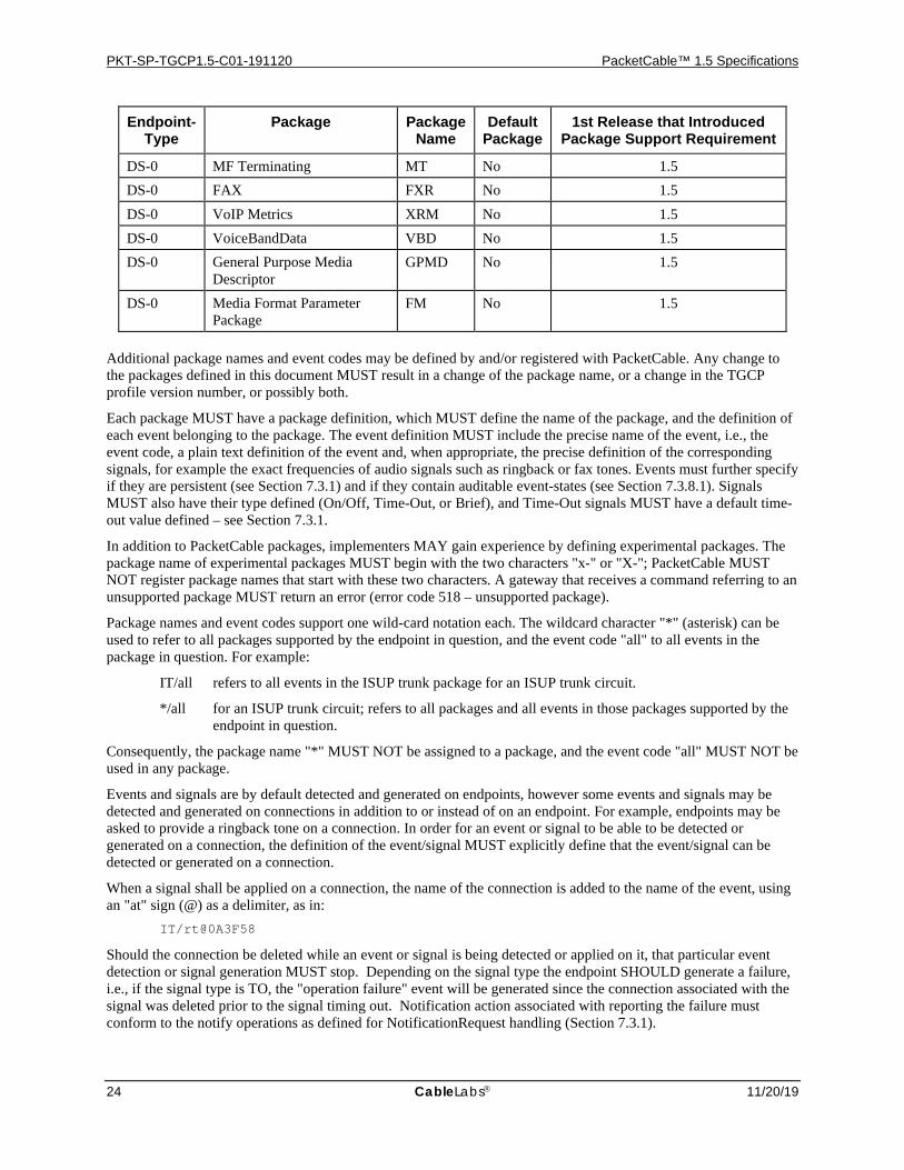
PKT-SP-TGCP1.5-C01-191120 PacketCable™ 1.5 Specifications
24 CableLabs 11/20/19
Endpoint-Type
Package Package Name
Default Package
1st Release that Introduced Package Support Requirement
DS-0 MF Terminating MT No 1.5 DS-0 FAX FXR No 1.5 DS-0 VoIP Metrics XRM No 1.5 DS-0 VoiceBandData VBD No 1.5 DS-0 General Purpose Media
Descriptor GPMD No 1.5
DS-0 Media Format Parameter Package
FM No 1.5
Additional package names and event codes may be defined by and/or registered with PacketCable. Any change to the packages defined in this document MUST result in a change of the package name, or a change in the TGCP profile version number, or possibly both.
Each package MUST have a package definition, which MUST define the name of the package, and the definition of each event belonging to the package. The event definition MUST include the precise name of the event, i.e., the event code, a plain text definition of the event and, when appropriate, the precise definition of the corresponding signals, for example the exact frequencies of audio signals such as ringback or fax tones. Events must further specify if they are persistent (see Section 7.3.1) and if they contain auditable event-states (see Section 7.3.8.1). Signals MUST also have their type defined (On/Off, Time-Out, or Brief), and Time-Out signals MUST have a default time-out value defined – see Section 7.3.1.
In addition to PacketCable packages, implementers MAY gain experience by defining experimental packages. The package name of experimental packages MUST begin with the two characters "x-" or "X-"; PacketCable MUST NOT register package names that start with these two characters. A gateway that receives a command referring to an unsupported package MUST return an error (error code 518 – unsupported package).
Package names and event codes support one wild-card notation each. The wildcard character "*" (asterisk) can be used to refer to all packages supported by the endpoint in question, and the event code "all" to all events in the package in question. For example:
IT/all refers to all events in the ISUP trunk package for an ISUP trunk circuit.
*/all for an ISUP trunk circuit; refers to all packages and all events in those packages supported by the endpoint in question.
Consequently, the package name "*" MUST NOT be assigned to a package, and the event code "all" MUST NOT be used in any package.
Events and signals are by default detected and generated on endpoints, however some events and signals may be detected and generated on connections in addition to or instead of on an endpoint. For example, endpoints may be asked to provide a ringback tone on a connection. In order for an event or signal to be able to be detected or generated on a connection, the definition of the event/signal MUST explicitly define that the event/signal can be detected or generated on a connection.
When a signal shall be applied on a connection, the name of the connection is added to the name of the event, using an "at" sign (@) as a delimiter, as in:
IT/rt@0A3F58
Should the connection be deleted while an event or signal is being detected or applied on it, that particular event detection or signal generation MUST stop. Depending on the signal type the endpoint SHOULD generate a failure, i.e., if the signal type is TO, the "operation failure" event will be generated since the connection associated with the signal was deleted prior to the signal timing out. Notification action associated with reporting the failure must conform to the notify operations as defined for NotificationRequest handling (Section 7.3.1).
PSTN Gateway Call Signaling Protocol Specification PKT-SP-TGCP1.5-C01-191120
11/20/19 CableLabs 25
The wildcard character "*" (asterisk) can be used to denote "all connections" on the affected endpoint(s). When this convention is used, the gateway MUST generate or detect the event on all the connections that are connected to the endpoint(s). An example of this convention is: IT/ma@*
However, when the event is actually observed, the gateway MUST include the name of the specific connection on which the event occurred. The wildcard character "$" (dollar sign) can be used to denote "the current connection". This convention MUST NOT be used unless the event notification request is "encapsulated" within a CreateConnection or ModifyConnection command. When the convention is used, the gateway MUST generate or detect the event on the connection that is currently being created or modified. An example of this convention is: IT/rt@$
When processing a command using the "current connection" wildcard, the "$" wildcard character MUST be expanded by the gateway to the value of the current connection. If a subsequent command either explicitly (e.g., by auditing) or implicitly (e.g., by persistence) refers to such an event, the expanded value MUST be used by the gateway. In other words, the "current connection" wildcard is expanded once, which is at the initial processing of the command in which it was explicitly included.
The connection id, or a wildcard replacement, can be used in conjunction with the "all packages" and "all events" conventions. The notation can be used to designate all events on all connections for the affected endpoint(s), for example: */all@*
However, the use of the "all packages" and "all events" wildcards are strongly discouraged. Call Agents must be able to operate in an environment where some endpoints do not support all packages. An endpoint that receives a command referencing a package it does not support will respond with error 518 (Unsupported or Unknown Package). On receiving this error response, the Call Agent could try the command again without the package parameter, although in the case where the original command contained parameters for multiple packages, the Call Agent would have no way of knowing which specific package(s) to exclude. The Call Agent can also use the AuditEndpoint command to determine the set of packages supported by an endpoint.
7.2 SDP Use The Media Gateway Controller uses the MGCP to provide the gateways with the description of connection parameters such as IP addresses, UDP port, and RTP profiles. Except where otherwise noted or implied in this specification, SDP descriptions MUST follow the conventions delineated in the session description protocol (SDP), which is now an IETF-proposed standard documented in [4]. In addition, all MGCs and media gateways MUST ignore any SDP parameters, attributes, or fields that are not understood by the call agent or gateway.
SDP allows for description of multimedia conferences. The TGCP profile will only support the setting of audio connections using the media type "audio".
SDP allows for description of real time fax using media type "image". The TGCP profile will support setting of fax connections using media type "image".
7.3 Gateway Control Functions This section describes the commands of the MGCP in the form of a remote procedure call (RPC) like API, which we will refer to as the media gateway control interface (MGCI). An MGCI function is defined for each MGCP command, where the MGCI function takes and returns the same parameters as the corresponding MGCP command. The functions shown in this section provide a high-level description of the operation of MGCP and describe an example of an RPC-like API that MAY be used for an implementation of MGCP. Although the MGCI API is merely an example API, the semantic behavior defined by MGCI is an integral part of the specification, and all implementations MUST conform to the semantics specified for MGCI. The actual MGCP messages exchanged, including the message formats and encodings used are defined in the protocol section (Section 8). Trunking gateways and Call Agents MUST implement those exactly as specified.
PKT-SP-TGCP1.5-C01-191120 PacketCable™ 1.5 Specifications
26 CableLabs 11/20/19
The MGCI service consists of connection handling and endpoint handling commands. The following is an overview of the commands:
• The Media Gateway Controller can issue a NotificationRequest command to a gateway, instructing the gateway to watch for specific events such as seizure or fax tones on a specified endpoint.
• The gateway will then use the Notify command to inform the Media Gateway Controller when the requested events occur on the specified endpoint.
• The Media Gateway Controller can use the CreateConnection command to create a connection that terminates in an endpoint inside the gateway.
• The Media Gateway Controller can use the ModifyConnection command to change the parameters associated to a previously established connection.
• The Media Gateway Controller can use the DeleteConnection command to delete an existing connection. In some circumstances, the DeleteConnection command also can be used by a gateway to indicate that a connection can no longer be sustained.
• The Media Gateway Controller can use the AuditEndpoint and AuditConnection commands to audit the status of an "endpoint" and any connections associated with it. Network management beyond the capabilities provided by these commands are generally desirable, e.g., information about the status of the trunking gateway and each of the trunk circuits. Such capabilities are expected to be supported by the use of the Simple Network Management Protocol (SNMP) and definition of a MIB, which is outside the scope of this specification.
• The gateway can use the RestartInProgress command to notify the Media Gateway Controller that the endpoint, or a group of endpoints managed by the gateway, is being taken out of service or is being placed back in service.
These services allow a controller (normally the Media Gateway Controller) to instruct a gateway on the creation of connections that terminate in an endpoint attached to the gateway, and to be informed about events occurring at the endpoint. Currently, a trunking gateway endpoint is limited to a specific trunk circuit within a trunking gateway.
Connections are grouped into "calls". Several connections, that may or may not belong to the same call, can terminate in the same endpoint. Each connection is qualified by a "mode" parameter, which can be set to "send only" (sendonly), "receive only" (recvonly), "send/receive" (sendrecv), "inactive" (inactive), "loopback" (loopback), "continuity test" (conttest), "network loopback" (netwloop) or "network continuity test" (netwtest). The "mode" parameter determines if media packets can be sent and/or received on the connection; however, RTCP is unaffected.
Audio signals received from the endpoint MUST be sent on any connection whose mode is either "send only" or "send/receive", unless the endpoint has a connection in "loopback" or "continuity test" mode. However, audio generated by applying a signal to a connection MUST be sent on the connection for all modes except "network loopback".
The handling of the audio signals received on these connections is also determined by the mode parameters:
• Audio signals received in data packets through connections in "inactive", "loopback" or "continuity test" mode MUST be discarded.
• Audio signals received in data packets through connections in "receive only" or "send/receive" mode MUST be mixed and sent to the endpoint, unless the endpoint has another connection in "loopback" or "continuity test" mode.
• Audio signals originating from the endpoint MUST be transmitted over all the connections whose mode is "send only" or "send/receive", unless the endpoint has another connection in "loopback" or "continuity test" mode.
Note that in order to detect events on a connection, the connection MUST by default be in one of the modes "receive only", "send/receive", "network loopback" or "network continuity test". The event detection only applies to the incoming audio. Connections in "send only", "inactive", "loopback", or "continuity test" mode will thus normally not detect any events, although requesting to do so is not considered an error.
PSTN Gateway Call Signaling Protocol Specification PKT-SP-TGCP1.5-C01-191120
11/20/19 CableLabs 27
The "loopback" and "continuity test" modes are used during maintenance and continuity test operations. An endpoint may have more than one connection in either "loopback" or "continuity test" mode. As long as there is one connection in that particular mode, and no other connection on the endpoint is placed in a different maintenance or test mode, the maintenance or test operation MUST continue undisturbed. There are two flavors of continuity test (COT), one specified by ITU and one used in the US. In the first case, the test is a loopback test. The originating switch will send a tone (the go tone) on the bearer circuit and expect the terminating switch to loopback the circuit. If the originating switch sees the same tone returned (the return tone), the COT has passed. If not, the COT has failed. In the second case, the go and return tones are different. The originating switch sends a certain go tone. The terminating switch detects the go tone, it asserts a different return tone in the backwards direction. When the originating switch detects the return tone, the COT is passed. If the originating switch does not detect the return tone within a certain period of time, the COT has failed.
If the mode is set to "loopback", the gateway MUST return the incoming signal from the endpoint back into that same endpoint. This procedure will be used, typically, for testing the continuity of trunk circuits according to the ITU specifications.
If the mode is set to "continuity test", the gateway is informed that the other end of the circuit has initiated a continuity test procedure according to procedures specified for US networks (see, e.g., [6]). The gateway will place the circuit in the transponder mode required for dual-tone continuity tests.
Furthermore, when a connection for an endpoint is in "loopback" or "continuity test" mode:
• Audio signals received on any connection for the endpoint MUST not be sent to the endpoint.
• Audio signals received on the endpoint MUST not be sent to any connection for the endpoint.
If the mode is set to "network loopback", the audio signals received from the connection MUST be echoed back on the same connection. The "network loopback" mode SHOULD simply operate as an RTP packet reflector. The media MUST not be forwarded to the endpoint. The "network continuity test" mode is used for continuity checking across the IP network. An endpoint-type specific signal is sent to the endpoints over the IP network, and the endpoint is then supposed to echo the signal over the IP network after passing it through the gateway's internal equipment to verify proper operation. The signal MUST go through internal decoding and re-encoding prior to being passed back. For DS-0 endpoints the signal will be an audio signal, and the signal MUST NOT be passed on to a circuit connected to the endpoint, regardless of the current seizure-state of that circuit. New and existing connections for the endpoint MUST NOT be affected by connections placed in "network loopback" or "network continuity test" mode. However, local resource constraints may limit the number of new connections that can be made.
Please refer to Appendix B for illustrations of mode interactions.
7.3.1 NotificationRequest The NotificationRequest command is used to request the gateway to send a notification upon the occurrence of specified events in an endpoint. For example, a notification may be requested when tones associated with fax communication are detected on the endpoint. The entity receiving this notification, usually the Media Gateway Controller, may then decide that a different type of encoding should be used on the connections bound to this endpoint and instruct the gateway accordingly5.
ReturnCode ← NotificationRequest(EndpointId [, NotifiedEntity] [, RequestedEvents] , RequestIdentifier [, SignalRequests] [, QuarantineHandling] [, DetectEvents])
5 The new instruction would be a ModifyConnection command.
PKT-SP-TGCP1.5-C01-191120 PacketCable™ 1.5 Specifications
28 CableLabs 11/20/19
EndpointId is the identifier for the endpoint(s) in the gateway where NotificationRequest executes. The EndpointId MUST follow the rules for endpoint names specified in Section 7.1.1. The "any of" wildcard MUST NOT be used. A gateway that receives a NotificationRequest with the "any of" wildcard convention MUST return an error (error returned SHOULD be error code 500 - the transaction could not be executed because the endpoint is unknown) in response. The "all of" wildcard MUST be supported for NotificationRequests with each of RequestedEvents, SignalsRequest, and DetectEvents being either empty or omitted. For simplicity, some gateways may choose to not support the "all-of" wildcard for NotificationRequests where one or more of these parameters is neither empty nor omitted. Such gateways shall respond with error code 503 if they receive an "all-of" wildcarded NotificationRequest which they are unable to process for this reason.
NotifiedEntity is an optional parameter that specifies a new "notified entity" for the endpoint. When used, the entire Media Gateway Controller name MUST be specified which includes both the local name and domain name - even if a bracketed IP address is used for the domain name. See Sections 7.1.1 and 7.1.4 for more information. If, however, only the domain name is provided, the MG SHOULD use the domain name as the Call Agent ID.
RequestIdentifier is used to correlate this request with the notification it may trigger. It will be repeated in the corresponding Notify command.
SignalRequests is a parameter that contains the set of signals that the gateway is asked to apply. Unless otherwise specified, signals are applied to the endpoint, however some signals can be applied to a connection. The following are examples of signals6:
• Continuity test
• Setup MF OSS call
Signals are divided into different types depending upon their behavior:
• On/off (OO) Once applied, these signals last until they are turned off. This can only happen as the result of a new SignalRequests where the signal is turned off (see later). Signals of type OO are defined to be idempotent, thus multiple requests to turn a given OO signal on (or off) are perfectly valid and MUST NOT result in any errors. Once turned on, it MUST NOT be turned off until explicitly instructed to by the Media Gateway Controller, or the endpoint restarts.
• Time-out (TO) Once applied, these signals last until they are either cancelled (by the occurrence of an event or by not being included in a subsequent [possibly empty] list of signals), or a signal-specific period of time has elapsed. A signal that times-out will generate an "operation complete" event. (Please see Appendix A for further definition of this event.) A TO signal could be "place MF call" timing out after 16 seconds. If an event occurs prior to the 16 seconds, the signal will, by default, be stopped7. If the signal is not stopped, the signal will time-out, stop and generate an "operation complete" event, about which the Media Gateway Controller may or may not have requested to be notified. If the Media Gateway Controller has asked for the "operation complete" event to be notified, the "operation complete" event sent to the Media Gateway Controller will include the name(s) of the signal(s) that timed out8. Signal(s) generated on a connection will include the name of that connection. Time-out signals have a default time-out value defined for them, which may be altered by the provisioning process. Also, the time-out period may be provided as a parameter to the signal. A value of zero indicates that the time-out period is infinite. A TO signal that fails after being started, but before having generated on "operation complete" event will generate an "operation failure" event which will include the name(s) of the signal(s) that time out8.
• Brief (BR) The duration of these signals is so short that they stop on their own. If a signal stopping event occurs, or a new SignalRequests is applied, a currently active BR signal will not stop. However, any pending BR signals not yet applied will be cancelled.
6 Please refer to Appendix A for a complete list of signals. 7 The "Keep signal(s) active" action may override this behavior. 8 If parameters were passed to the signal, the parameters will not be reported.

PSTN Gateway Call Signaling Protocol Specification PKT-SP-TGCP1.5-C01-191120
11/20/19 CableLabs 29
Signals are, by default, applied to endpoints. If a signal applied to an endpoint results in the generation of a media stream (audio, video, etc.), the media stream MUST NOT be forwarded on any connection associated with that endpoint, regardless of the mode of the connection. For example, if a tone is applied to an endpoint involved in an active communication, only the party using the endpoint in question will hear the tone. However, individual signals may define a different behavior.
When a signal is applied to a connection that has received a RemoteConnectionDescriptor (see Section 7.3.3), the media stream generated by that signal MUST be forwarded on the connection regardless of the current mode of the connection. If a RemoteConnectionDescriptor has not been received, the gateway MUST return an error (error code 527 – missing RemoteConnectionDescriptor).
When a (possibly empty) list of signal(s) is supplied, this list completely replaces the current list of active time-out signals. Currently active time-out signals that are not provided in the new list MUST be stopped and the new signal(s) provided will now become active. Currently active time-out signals that are provided in the new list of signals MUST remain active without interruption, thus the timer for such time-out signals will not be affected. Consequently, there is currently no way to restart the timer for a currently active time-out signal without turning the signal off first. If the time-out signal is parameterized, the original set of parameters MUST remain in effect, regardless of what values are provided subsequently. A given signal MUST NOT appear more than once in a SignalRequests. The omission of the SignalRequests parameter is interpreted as an empty SignalRequests list.
The currently defined signals can be found in Appendix A.
RequestedEvents is a list of events that the gateway is requested to detect on the endpoint. Unless otherwise specified, events are detected on the endpoint, however some events can be detected on a connection. Examples of events are:
• seizure
• fax tones,
• operation complete
• Incoming MF call
The currently defined events can be found in Appendix A.
To each event is associated one or more actions that define the action that the gateway MUST take when the event in question occurs. The possible actions are:
• Notify the event immediately, together with the accumulated list of observed events,
• Accumulate the event,
• Ignore the event,
• Keep Signal(s) active,
• Embedded NotificationRequest,
• Embedded ModifyConnection.
Two sets of requested events will be detected by the endpoint: persistent and non-persistent.
Persistent events are always detected on an endpoint. If a persistent event is not included in the list of RequestedEvents, and the event occurs, the event will be detected anyway, and processed like all other events, as if the persistent event had been requested with a Notify action9. Thus, informally, persistent events can be viewed as always being implicitly included in the list of RequestedEvents with an action to Notify, although no glare detection, etc., will be performed10. Persistent events are identified as such through their definition – see Appendix A.
9 Thus the RequestIdentifier will be the RequestIdentifier of the current NotificationRequest (includes notification request
embedded in connection handling primitives). 10 Normally, if a request to look for, e.g., off-hook, is made, the request is only successful if the phone is not already
off-hook.
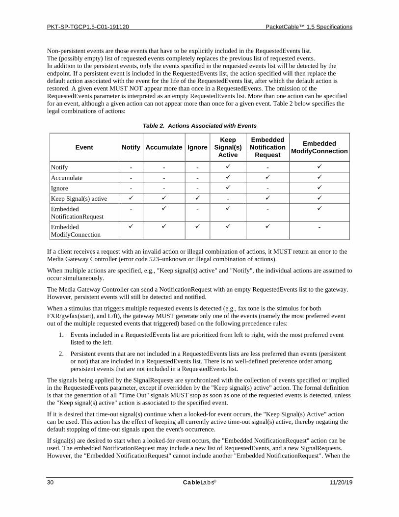
PKT-SP-TGCP1.5-C01-191120 PacketCable™ 1.5 Specifications
30 CableLabs 11/20/19
Non-persistent events are those events that have to be explicitly included in the RequestedEvents list. The (possibly empty) list of requested events completely replaces the previous list of requested events. In addition to the persistent events, only the events specified in the requested events list will be detected by the endpoint. If a persistent event is included in the RequestedEvents list, the action specified will then replace the default action associated with the event for the life of the RequestedEvents list, after which the default action is restored. A given event MUST NOT appear more than once in a RequestedEvents. The omission of the RequestedEvents parameter is interpreted as an empty RequestedEvents list. More than one action can be specified for an event, although a given action can not appear more than once for a given event. Table 2 below specifies the legal combinations of actions:
Table 2. Actions Associated with Events
Event Notify Accumulate Ignore Keep
Signal(s) Active
Embedded Notification
Request Embedded
ModifyConnection
Notify - - - - Accumulate - - - Ignore - - - - Keep Signal(s) active - Embedded NotificationRequest
- - -
Embedded ModifyConnection
-
If a client receives a request with an invalid action or illegal combination of actions, it MUST return an error to the Media Gateway Controller (error code 523–unknown or illegal combination of actions).
When multiple actions are specified, e.g., "Keep signal(s) active" and "Notify", the individual actions are assumed to occur simultaneously.
The Media Gateway Controller can send a NotificationRequest with an empty RequestedEvents list to the gateway. However, persistent events will still be detected and notified.
When a stimulus that triggers multiple requested events is detected (e.g., fax tone is the stimulus for both FXR/gwfax(start), and L/ft), the gateway MUST generate only one of the events (namely the most preferred event out of the multiple requested events that triggered) based on the following precedence rules:
1. Events included in a RequestedEvents list are prioritized from left to right, with the most preferred event listed to the left.
2. Persistent events that are not included in a RequestedEvents lists are less preferred than events (persistent or not) that are included in a RequestedEvents list. There is no well-defined preference order among persistent events that are not included in a RequestedEvents list.
The signals being applied by the SignalRequests are synchronized with the collection of events specified or implied in the RequestedEvents parameter, except if overridden by the "Keep signal(s) active" action. The formal definition is that the generation of all "Time Out" signals MUST stop as soon as one of the requested events is detected, unless the "Keep signal(s) active" action is associated to the specified event.
If it is desired that time-out signal(s) continue when a looked-for event occurs, the "Keep Signal(s) Active" action can be used. This action has the effect of keeping all currently active time-out signal(s) active, thereby negating the default stopping of time-out signals upon the event's occurrence.
If signal(s) are desired to start when a looked-for event occurs, the "Embedded NotificationRequest" action can be used. The embedded NotificationRequest may include a new list of RequestedEvents, and a new SignalRequests. However, the "Embedded NotificationRequest" cannot include another "Embedded NotificationRequest". When the
PSTN Gateway Call Signaling Protocol Specification PKT-SP-TGCP1.5-C01-191120
11/20/19 CableLabs 31
"Embedded NotificationRequest" is activated, the list of observed events and the quarantine buffer will be unaffected (see Section 7.4.3.1).
The embedded NotificationRequest action allows the Media Gateway Controller to set up a "mini-script" to be processed by the gateway immediately following the detection of the associated event. Any SignalRequests specified in the embedded NotificationRequest will start immediately. Considerable care must be taken to prevent discrepancies between the Media Gateway Controller and the gateway. However, long-term discrepancies should not occur as new SignalRequests completely replaces the old list of active time-out signals, and BR-type signals always stop on their own. Limiting the number of On/Off-type signals is encouraged. It is considered good practice for a Media Gateway Controller to occasionally turn on all On/Off signals that should be on, and turn off all On/Off signals that should be off.
If connection modes are desired to be changed when a looked-for event occurs, the "Embedded ModifyConnection" action can be used. The embedded ModifyConnection may include a list of connection mode changes each consisting of the mode change and the affected connection-id. The wildcard "$" can be used to denote "the current connection", however this notation MUST NOT be used outside a connection handling command – the wildcard refers to the connection in question for the connection handling command.
The embedded ModifyConnection action allows the Media Gateway Controller to instruct the endpoint to change the connection mode of one or more connections immediately following the detection of the associated event. Each of connection mode changes work similarly to a corresponding ModifyConnection command. When a list of connection mode changes is supplied, the connection mode changes MUST be applied one at a time in left-to-right order. When all the connection mode changes have finished, an "operation complete" event parameterized with the name of the completed action will be generated (see Appendix A for details). Should any of the connection mode changes fail, an "operation failure" event parameterized with the name of the failed action and connection mode change will be generated (see Appendix A for details) - the rest of the connection mode changes MUST NOT be attempted, and the previous successful connection mode changes in the list MUST remain effective.
Finally, the Ignore action can be used to ignore an event, e.g., to prevent a persistent event from being notified. However, the synchronization between the event and an active signal will still occur by default.
Section 7.4.3.1 contains additional details on the semantics of event detection and reporting. The reader is encouraged to study it carefully.
The specific definition of actions that are requested via these SignalRequests is outside the scope of the core TGCP Specification. This definition may vary from location to location and, hence, from gateway to gateway. Consequently, the definitions are provided in event packages, which may be provided outside of the core specification. An initial list of event packages can be found in Appendix A.
The RequestedEvents and SignalRequests generally refer to the same events. In one case, the gateway is asked to detect the occurrence of the event and, in the other case, it is asked to generate it. There are only a few exceptions to this rule, notably the fax and modem tones, which can be detected but cannot be signaled. However, we necessarily cannot expect all endpoints to detect all events. The specific events and signals that a given endpoint can detect or perform are determined by the list of event packages that are supported by that endpoint. Each package specifies a list of events and signals that can be detected or applied. A gateway that is requested to detect or to apply an event that is not supported by the specified endpoint MUST return an error (error code 512 or 513 – not equipped to detect event or generate signal). When the event name is not qualified by a package name, the default package name for the endpoint is assumed. If the event name is not registered in this default package, the gateway MUST return an error (error code 522 – no such event or signal).
The Media Gateway Controller can send a NotificationRequest whose requested signal list is empty. This has the effect of stopping all active time-out signals. It can do so, for example, when tone generation, e.g., ringback, should stop.
QuarantineHandling is an optional parameter that specifies handling options for the quarantine buffer (see Section 7.4.3.1), i.e., events that have been detected by the gateway before the arrival of this notificationRequest command, but have not yet been notified to the MGC. The parameter provides a set of handling options:
• whether the quarantined events should be processed or discarded (the default is to process them)
PKT-SP-TGCP1.5-C01-191120 PacketCable™ 1.5 Specifications
32 CableLabs 11/20/19
• whether the gateway is expected to generate at most one notification (lockstep), or multiple notifications (loop), in response to this request (the default is at most one)
When the parameter is absent, the quarantined events MUST be processed. Support for the "lockstep" mode (via default) and "loop" mode is mandatory. An endpoint that receives a NotificationRequest with an unsupported QuarantineHandling parameter value SHOULD respond with error code 508 (unsupported QuarantineHandling ).
Note that the quarantine-handling parameter also governs the handling of events that were detected and processed but not yet notified when the command is received.
DetectEvents is an optional parameter that specifies a minimum list of events that the gateway is requested to detect in the "notification" and "lockstep" state. The list is persistent until a new value is specified. Further explanation of this parameter may be found in Section 7.4.3.1.
ReturnCode is a parameter returned by the gateway. It indicates the outcome of the command and consists of an integer number (see Section 7.5) optionally followed by commentary.
7.3.2 Notifications Notifications are sent via the Notify command by the gateway when an observed event is to be notified:
ReturnCode ← Notify(EndpointId [, NotifiedEntity] , RequestIdentifier , ObservedEvents)
EndpointId is the name for the endpoint in the gateway, which is issuing the Notify command, as defined in Section 7.1.1. The identifier MUST be a fully qualified endpoint name, including the domain name of the gateway. The local part of the name MUST NOT use the wildcard convention. A MGC that receives a Notification with wildcard convention MUST return an error (error returned SHOULD be error code 500 - the transaction could not be executed because the endpoint is unknown) in response.
NotifiedEntity is an optional parameter that identifies the entity to which the notification is sent. This parameter is equal to the NotifiedEntity parameter of the NotificationRequest that triggered this notification. Note that the MG MAY include only the domain name of its Notified Entity if only the domain name was received in the triggering NotificationRequest. The MGC SHOULD accept the value in this case. The parameter is absent if there was no such parameter in the triggering request. Regardless of the value of the "NotifiedEntity parameter, the notification MUST be sent to the current "notified entity" for the endpoint.
RequestIdentifier is a parameter that repeats the RequestIdentifier parameter of the NotificationRequest that triggered this notification. It is used to correlate this notification with the notification request that triggered it. Persistent events will be viewed here as if they had been included in the last NotificationRequest (includes notification request embedded in connection handling primitives). When no NotificationRequest has been received, the RequestIdentifier used will be zero ("0").
ObservedEvents is a list of events that the gateway detected and accumulated, either by the "accumulate", or "notify" action. A single notification can report a list of events that will be reported in the order in which they were detected. The list can only contain persistent events and events that were requested in the RequestedEvents parameter of the triggering NotificationRequest. Events that were detected on a connection will include the name of that connection. The list will contain the events that were either accumulated (but not notified), and the final event that triggered the notification.
ReturnCode is a parameter returned by the Media Gateway Controller. It indicates the outcome of the command and consists of an integer number (see Section 7.5) optionally followed by commentary.
7.3.3 CreateConnection This command is used to create a connection.
ReturnCode [, ConnectionId] [, SpecificEndPointId] [, LocalConnectionDescriptor]
PSTN Gateway Call Signaling Protocol Specification PKT-SP-TGCP1.5-C01-191120
11/20/19 CableLabs 33
← CreateConnection(CallId , EndpointId [, NotifiedEntity] [, LocalConnectionOptions] , Mode [, RemoteConnectionDescriptor] [, RequestedEvents] [, RequestIdentifier] [, SignalRequests] [, QuarantineHandling] [, DetectEvents])
This function is used when setting up a connection between two endpoints. A connection is defined by its attributes and the endpoints it associates. At a minimum, a Trunking Gateway MUST support one connection per endpoint. The input parameters in CreateConnection provide the data necessary to build one of the two endpoints "view" of a connection.
CallId is a parameter that identifies the call (or session) to which this connection belongs. This parameter is, at a minimum, unique within the collection of Media Gateway Controllers that control the same gateways; connections that belong to the same call share the same call-id. The call-id can be used to identify calls for reporting and accounting purposes.
EndpointId is the identifier for the endpoint in the gateway where CreateConnection executes. The EndpointId can be specified fully by assigning a non-wildcarded value to the parameter EndpointId in the function call or it can be under-specified by using the "anyone" wildcard convention. If the endpoint is under-specified, the endpoint identifier will be assigned by the gateway and its complete value MUST be returned in the SpecificEndPointId parameter of the response only if the command is successful. In this case, the endpoint assigned MUST be in service and MUST NOT already have any connections on it. The "all" wildcard convention MUST NOT be used. A gateway that receives a CreateConnection with the "all" wildcard convention MUST return an error (error returned SHOULD be error code 500 - the transaction could not be executed because the endpoint is unknown) in response.
NotifiedEntity is an optional parameter that specifies a new "notified entity" for the endpoint.
LocalConnectionOptions is a structure that describes the characteristics of the media data connection from the point-of-view of the gateway executing CreateConnection. It instructs the endpoint on send and receive characteristics of the media connection. The basic fields contained in LocalConnectionOptions are:
• Encoding Method A list of literal names for the compression algorithm (encoding/decoding method) used to send and receive media on the connection MUST be specified with at least one value. The entries in the list are ordered by preference. The endpoint MUST choose at least one of the codecs, and the codec(s) SHOULD be chosen according to the preference indicated. If the endpoint receives any media on the connection encoded with a different encoding method, it MAY discard it. The endpoint MUST additionally indicate which of the remaining compression algorithms it is willing to support as alternatives - see Section 8.4.1 for details. A list of permissible encoding methods is specified in the PacketCable Audio/Video Codecs Specification [11]. The literal names defined in Table 4 of the Audio/Video Codecs specification MUST be used. Unknown compression algorithms SHOULD be ignored if they are received. See Section 7.7 for details on the codec selection process. Note: "encoding method" includes audio, image, and video encodings.
• Packetization Period A single packetization period in milliseconds MAY be specified with exactly one decimal value. If this specifier is used, then the same packetization period MUST be used for all encoding methods allowed by the LocalConnectionOptions. Note that if no encoding method field is specified in the LCO, the MG MUST NOT choose an encoding method with a packetization period that differs from that specified here. If different packetization periods for different encoding methods is desired, then this field MUST NOT be used. The value pertains to both media sent and received. Note that only the valid packetization period in conjunction with the associated encoding method or methods are to be used by the MG. A list of permissible packetization periods is specified in the PacketCable Audio/Video Codecs Specification [11]. This specifier MUST NOT be supplied in the same LCO as the Multiple Packetization
PKT-SP-TGCP1.5-C01-191120 PacketCable™ 1.5 Specifications
34 CableLabs 11/20/19
Period field. An MG MUST return an error (error code 524 – inconsistency in LocalConnectionOptions) when it receives an LCO with both the Packetization Period and Multiple Packetization Period fields.
• Multiple Packetization Period: A list of packetization periods in milliseconds, MAY be specified if, and only if, the Encoding Method field is included. When specified, the multiple packetization period in milliseconds MUST contain exactly one decimal value or a hyphen for each entry in the encoding method field included in the LocalConnectionOptions. This applies even if several of the encoding methods have the same value. The first entry in the list MUST be a decimal number. When a hyphen is used, the encoding method in question MUST use the same packetization period as one of the other entries in the list that actually contains a decimal number, and furthermore the encoding method in question MUST NOT consume any more bandwidth than the other entry. This can for example be used for non-voice codecs (e.g. telephone-event or comfort noise) that use the same packetization period as the voice codec with which they are being used. Successive entries in the list of packetization periods MUST be ordered identically to the corresponding encoding methods. The values pertain to both media sent and received. Note that the MG MUST NOT choose a codec with a packetization period that differs from that specified here. Note that only the valid packetization period in conjunction with the associated encoding method is to be used by the MG. A list of permissible packetization periods is specified in the PacketCable Audio/Video Codecs Specification [11]. This specifier MUST NOT be supplied in the same LCO as the Packetization Period field. An MG MUST return an error (error code 524 – inconsistency in LocalConnectionOptions) under the following conditions :
• When it receives an LCO with both the Packetization Period and Multiple Packetization Period fields.
• When it receives an LCO where the number of codecs specified in the Encoding Method field is different from the number of elements in the Multiple Packetization Period field.
• Echo Cancellation Whether echo cancellation should be used initially on the line side or not. The parameter can have the value "on" (when the echo cancellation is requested) or "off" (when it is turned off). The parameter is optional. When the parameter is omitted, the media gateway MUST apply echo cancellation initially. The media gateway SHOULD subsequently enable or disable echo cancellation in accordance with [19] and [10] when voiceband data is detected. For re-enabling echo cancellation see G.168. Following termination of voiceband data, the handling of echo cancellation MUST revert to the current value of the echo cancellation parameter. It is RECOMMENDED that echo cancellation handling is left to the gateway rather than having this parameter specified by the MGC.
• Type of Service Specifies the class of service that will be used for sending media on the connection by encoding the 8-bit type of service value parameter of the IP header as two hexadecimal digits. The parameter is optional. When the parameter is omitted, a default value of 0x00 (unless provisioned otherwise) MUST be used. When this parameter is present and valid, the endpoint MUST use the value provided to populate the differentiated services codepoint (DSCP) parameter in the IP header (see [25] for more information on the DSCP). The parameter value MUST be 0x00, or MUST be a multiple of four in the range of 0x01 to 0xFF (bits 6 and 7, the ECN bits, are reserved and hence must be set to "00"). An endpoint MUST return an error (error code 532 – Unsupported value(s) in LocalConnectionOptions) when it receives an invalid value. The left-most "bit" in the parameter corresponds to the most significant bit in the IP header.
• Silence Suppression The telephony gateways may perform voice activity detection, and avoid sending packets during periods of silence. However, it is necessary for certain call types (e.g., modem calls) to disable silence suppression. The parameter can have the value "on" (when silence is to be suppressed) or "off" (when silence is not to be suppressed). The parameter is optional. When the parameter is omitted, the default value is "off". If the value is "on", upon detecting voiceband data, the endpoint SHOULD disable silence suppression. Following termination of voiceband data, the handling of silence suppression MUST revert to the current value of the silence suppression parameter.
Additionally, the following LocalConnectionOptions fields are used to support the PacketCable security services: (Either or both ciphersuites MAY be present).
• RTP ciphersuite A list of ciphersuites for RTP security in order of preference. The entries in the list are ordered by preference where the first ciphersuite is the preferred choice. The endpoint MUST choose exactly one of the ciphersuites according to the rules described in the PacketCable Security Specification
PSTN Gateway Call Signaling Protocol Specification PKT-SP-TGCP1.5-C01-191120
11/20/19 CableLabs 35
[12]. The endpoint SHOULD additionally indicate which of the remaining ciphersuites it is willing to support as alternatives (see Section 8.4.1 for details). Each ciphersuite is represented as ASCII strings consisting of two (possibly empty) substrings separated by a slash ("/"), where the first substring identifies the authentication algorithm, and the second substring identifies the encryption algorithm. A list of permissible ciphersuites are specified in the PacketCable Security Specification [12]. The RTP ciphersuite parameter applies to RTP media streams only. If the MGC includes LocalConnectionOptions that require use of non-RTP media only (as for example T.38 fax relay using UDPTL), the RTP ciphersuite parameter MUST NOT be included. If an LCO allows both RTP and non-RTP media and an RTP ciphersuite parameter is included, it applies to the RTP media only. In all cases, if the resulting media stream on the connection is not an RTP media stream (as for example T.38 fax relay using UDPTL), the RTP ciphersuite parameter MUST be ignored, i.e., RTP security is not being used, and RTP security parameters are not included in LocalConnectionDescriptor.
• RTCP ciphersuite A list of ciphersuites for RTCP security in order of preference. The entries in the list are ordered by preference where the first ciphersuite is the preferred choice. The endpoint MUST choose exactly one of the ciphersuites according to the rule described in the PacketCable Security Specification [12]. The endpoint SHOULD additionally indicate which of the remaining ciphersuites it is willing to support as alternatives. See Section 8.4.1 for details. Each ciphersuite is represented as ASCII strings consisting of two (possibly empty) substrings separated by a slash ("/"), where the first substring identifies the authentication algorithm, and the second substring identifies the encryption algorithm. A list of permissible ciphersuites are specified in the PacketCable Security Specification [12]. The RTCP ciphersuite parameter applies to RTCP for RTP media streams only. If the MGC includes LocalConnectionOptions that require use of non-RTP media only (as for example T.38 fax relay using UDPTL), the RTCP ciphersuite parameter MUST NOT be included. If an LCO allows both RTP and non-RTP media and an RTCP ciphersuite parameter is included, it applies to RTCP for the RTP media only. In all cases, if the resulting media stream on the connection is not an RTP media stream (as for example T.38 fax relay using UDPTL), the RTCP ciphersuite parameter MUST be ignored, i.e., RTCP security is not being used, and RTCP security parameters are not included in LocalConnectionDescriptor.
The trunking gateway MUST respond with an error (error code 524 – LocalConnectionOptions inconsistency) if any of the above rules are violated. All of the above mentioned default values can be altered by the provisioning process.
Furthermore, TGCP supports PacketCable Electronic Surveillance Protocol Specification [14]. When a connection is subject to electronic surveillance, all valid media packets received on the connection and all media packets sent on the connection will be replicated and forwarded to an Electronic Surveillance Delivery Function11 after inclusion of a Call Content Connection Identifier. The replication will follow the connection mode for the connection, except for media generated by signals applied to the connection, which will be replicated regardless of the connection mode. For example, a connection in "inactive" mode will not generate any intercepted media12, whereas a connection in "sendonly" mode will only generate intercepted media in the send direction. Replicated packets will not be included in statistics for the connection. The following LocalConnectionOptions fields are used to support PacketCable Electronic Surveillance (see [14] for details):
• Call Content Connection Identifier: The Call Content Connection (CCC) Identifier is a 32-bit value that specifies the Call Content Connection Identifier to be used for connections that are subject to electronic surveillance. It will be added to the header of intercepted voice packets.
• Call Content Destination: The Call Content Destination specifies an IPv4 address followed by a colon and a UDP port number. The Call Content Destination specifies the destination IP address and port for the call content intercepted.
RemoteConnectionDescriptor is the connection descriptor for the remote side of a connection, on the other side of the IP network. It includes the same fields as the LocalConnectionDescriptor (not to be confused with LocalConnectionOptions), i.e., the fields that describe a session according to the SDP standard. Section 8.4 details the supported use of SDP in the TGCP profile. This parameter may have a null value when the information for the
11 Note that the replication occurs at the network level – see [14] for details. 12 Assuming no media generating signal was applied to the connection.
PKT-SP-TGCP1.5-C01-191120 PacketCable™ 1.5 Specifications
36 CableLabs 11/20/19
remote end is not known. This occurs because the entity that builds a connection starts by sending a CreateConnection to one of the two gateways involved. For the first CreateConnection issued, there is no information available about the other side of the connection. This information may be provided later via a ModifyConnection call.
When codecs are changed during a communication, small periods of time may exist where the endpoints use different codes. As stated above, trunking gateways MAY discard any media received that is encoded with a different codec than what is specified in the LocalConnectionOptions for a connection.
Mode indicates the mode of operation for this side of the connection. The options are "send only", "receive only", "send/receive", "inactive", "loopback", "continuity test", "network loopback" or "network continuity test". The handling of these modes is specified in the beginning of Section 7.3. Note that signals applied to a connection do not follow the connection mode. Some endpoints may not be capable of supporting all modes – see Appendix E.1. If the command specifies a mode that the endpoint does not support, an error MUST be returned (error code 517 – unsupported mode). Also, if a connection has not yet received a RemoteConnectionDescriptor, an error MUST be returned if the connection is attempted to be placed in any of the modes "send only", or "send/receive", "network loopback", "network continuity test", or if a signal (as opposed to detecting an event) is to be applied to the connection (error code 527 – missing RemoteConnectionDescriptor is RECOMMENDED).
ConnectionId is a parameter returned by the gateway that uniquely identifies the connection within the context of the endpoint in question. The parameter MUST be included with any provisional or successful response to a CreateConnection command. The parameter MUST NOT be included when any error response is returned, and the connection was not created.
LocalConnectionDescriptor is a parameter returned by the gateway, which is a session description that contains information about, e.g., addresses and RTP ports for "IN" connections as defined in SDP. It is similar to the RemoteConnectionDescriptor, except that it specifies this side of the connection. Section 8.4 details the supported use of SDP in the TGCP profile. The LocalConnectionDescriptor parameter MUST be included with any provisional or successful response to a CreateConnection command. The LocalConnectionDescriptor MUST NOT be included when any error response is returned, and the connection was not created.
After receiving a "CreateConnection" command that does not include a RemoteConnectionDescriptor parameter, a gateway is in an ambiguous situation for the connection in question. Because it has exported a LocalConnectionDescriptor parameter, it potentially can receive packets on that connection. Because it has not yet received the other gateway's RemoteConnectionDescriptor parameter, it does not know whether the packets it receives have been authorized by the Media Gateway Controller. Thus, it must navigate between two risks, i.e., clipping some important announcements or listening to insane data. The behavior of the gateway is determined by the value of the mode parameter (subject to security):
• If the mode was set to "receive only", the gateway MUST accept the voice signals received on the connection and transmit them through to the endpoint.
• If the mode was set to "inactive", "loopback", or "continuity test" the gateway MUST (as always) discard the voice signals received on the connection.
• If the mode was set to "network loopback" or "network continuity test" the gateway MUST perform the expected echo or response. The echoed or generated media MUST then be sent to the source of the media received.
• Note that when the endpoint does not have a RemoteConnectionDescriptor for the connection, the connection can by definition not be in any of the modes "send only", or "send/receive".
The RequestedEvents, RequestIdentifier, SignalRequests, QuarantineHandling, and DetectEvents parameters are all optional. They can be used by the Media Gateway Controller to effectively include an embedded notification request that is executed simultaneously with the creation of the connection. If one or more of these parameters is present, the RequestIdentifier MUST be one of them. Thus, the inclusion of a notification request can be recognized by the presence of a RequestIdentifier. The rest of the parameters may or may not be present. If one of the parameters is not present, it MUST be treated as if it was a normal NotificationRequest with the parameter in question being omitted. This may have the effect of canceling signals and of stop looking for events. Note that
PSTN Gateway Call Signaling Protocol Specification PKT-SP-TGCP1.5-C01-191120
11/20/19 CableLabs 37
absence of the RequestedEvents and SignalRequests parameters is interpreted as an empty list only if a RequestIdentifier parameter is included.
As an example of use, consider a Media Gateway Controller that wants to place a call to an operator services system through an MF trunking gateway. The Media Gateway Controller could:
• ask the trunking gateway to create a connection, in order to be sure that the media gateway has resources for the call,
• ask the trunking gateway to seize an MF operator services trunk and initiate the call,
• ask the trunking gateway to notify the Media Gateway Controller when the call has been placed.
All of the above can be accomplished in a single CreateConnection command by including a notification request with the RequestedEvents parameters for the answer event and the SignalRequests parameter for the setup signal.
When these parameters are present, the creation of the connection and the notification request MUST be synchronized, which means that they are both either accepted or refused. In our example, the CreateConnection must be refused if the gateway does not have sufficient resources or cannot get adequate resources from the local network access. The call initiation notification request must be refused in the glare condition if the circuit is already seized. In this example, the call must not be placed if the connection cannot be established, and the connection must not be established if the circuit is already seized. An error would be returned instead (error code 401 – circuit already seized), which informs the Media Gateway Controller of the glare condition.
ReturnCode is a parameter returned by the gateway. It indicates the outcome of the command and consists of an integer number (see Section 7.5) optionally followed by commentary.
7.3.4 ModifyConnection This command is used to modify the characteristics of a gateway's "view" of a connection. This "view" of the call includes both the local connection descriptor, as well as the remote connection descriptor.
ReturnCode [, LocalConnectionDescriptor] ← ModifyConnection(CallId , EndpointId , ConnectionId [, NotifiedEntity] [, LocalConnectionOptions] [, Mode] [, RemoteConnectionDescriptor] [, RequestedEvents] [, RequestIdentifier] [, SignalRequests] [, QuarantineHandling] [, DetectEvents])
The parameters used are the same as in the CreateConnection command, with the addition of a ConnectionId that uniquely identifies the connection within the endpoint. This parameter is returned by the CreateConnection command together with the local connection descriptor. It uniquely identifies the connection within the context of the endpoint.
The EndpointId MUST be a fully qualified endpoint name. The local name MUST NOT use the wildcard convention. A gateway that receives a ModifyConnection with a wildcard convention MUST return an error (error returned SHOULD be error code 500 - the transaction could not be executed because the endpoint is unknown) in response.
The ModifyConnection command can be used to affect connection parameters, subject to the same rules and constraints as specified for CreateConnection:
• Provide information on the other end of the connection through the RemoteConnectionDescriptor.
PKT-SP-TGCP1.5-C01-191120 PacketCable™ 1.5 Specifications
38 CableLabs 11/20/19
• Activate or deactivate the connection by changing the mode parameter's value. This can occur at any time during the connection, with arbitrary parameter values. An activation can, for example, be set to the "receive only" mode.
• Change the parameters of the connection through the LocalConnectionOptions, for example, by switching to a different coding scheme, changing the packetization period, or modifying the handling of echo cancellation.
The command will only return a LocalConnectionDescriptor if the local connection parameters, such as, e.g., RTP ports, etc. are modified. Thus, if, e.g., only the mode of the connection is changed, a LocalConnectionDescriptor will not be returned. The LocalConnectionDescriptor parameter MUST NOT be included when any error response is returned, and the connection was not modified. If a connection parameter is omitted, e.g., mode or silence suppression, the old value of that parameter will be retained if possible. If a parameter change necessitates a change in one or more unspecified parameters, the gateway is free to choose suitable values for the unspecified parameters that must change13.
The RTP address information provided in the RemoteConnectionDescriptor specifies the remote RTP address of the receiver of media for the connection. This RTP address information may have been changed by the Media Gateway Controller14. When RTP address information is given to a trunking gateway for a connection, the trunking gateway SHOULD only accept media streams (and RTCP) from the RTP address specified as well. Any media streams received from any other addresses SHOULD be discarded. The PacketCable Security Specification [12] should be consulted for additional security requirements.
The RequestedEvents, RequestIdentifier, SignalRequests, QuarantineHandling, and DetectEvents parameters are optional. The parameters can be used by the Media Gateway Controller to include an embedded notification request that is tied to and executed simultaneously with the connection modification. If one or more of these parameters is supplied, then RequestIdentifier MUST be one of them. Note that absence of the RequestedEvents and SignalRequests parameters is interpreted as an empty list only if a RequestIdentifier parameter is included.
When these parameters are present, the connection modification and the notification request MUST be synchronized, which means that they are both either accepted or refused.
NotifiedEntity is an optional parameter that specifies a new "notified entity" for the endpoint.
ReturnCode is a parameter returned by the gateway. It indicates the outcome of the command and consists of an integer number (see Section 7.5) optionally followed by commentary.
7.3.5 DeleteConnection (From the Media Gateway Controller) This command is used to terminate a connection. As a side effect, it collects statistics on the execution of the connection.
13 This can for instance happen if a codec change is specified, and the old codec used silence suppression, but the new one does not support it. If, e.g., the packetization period furthermore was not specified, and the new codec supported the old packetization period, the value of this parameter would not change, as a change would not be necessary. 14 For instance if media needs to traverse a firewall.
PSTN Gateway Call Signaling Protocol Specification PKT-SP-TGCP1.5-C01-191120
11/20/19 CableLabs 39
ReturnCode [, Connection-parameters ] ← DeleteConnection(CallId , EndpointId , ConnectionId [, NotifiedEntity] [, RequestedEvents] [, RequestIdentifier] [, SignalRequests] [, QuarantineHandling] [, DetectEvents])
The endpoint identifier, in this form of the DeleteConnection command, MUST be fully qualified. Wildcard conventions MUST NOT be used. A gateway that receives this form of the DeleteConnection with a wildcard convention MUST return an error (error returned SHOULD be error code 500 - the transaction could not be executed because the endpoint is unknown) in response.
In the general case where a connection has two ends, this command has to be sent to both gateways involved in the connection. After the connection has been deleted, packet network media streams previously supported by the connection are no longer available. Any media packets received for the old connection are simply discarded and no new media packets for the stream are sent. Also, after the connection has been deleted, any loopback that has been requested for the connection MUST be cancelled (unless the endpoint has another connection requesting loopback).
In response to the DeleteConnection command, the gateway returns a list of parameters that describe the status of the connection.15 The connection parameters MUST only be returned if the command is successful and the connection is deleted. These parameters are:
• Number of packets sent The total number of RTP data packets transmitted by the sender since starting transmission on the connection. The count is not reset if the sender changes its synchronization source identifier (SSRC, as defined in RTP)—for example, as a result of a Modify command. The value MUST be based on the same information provided via the RTCP mechanism.
• Number of octets sent The total number of payload octets (i.e., not including header or padding) transmitted in RTP data packets by the sender since starting transmission on the connection. The count is not reset if the sender changes its SSRC identifier—for example, as a result of a ModifyConnection command. The value MUST be based on the same information provided via the RTCP mechanism.
• Number of packets received The total number of RTP data packets received by the sender since starting reception on the connection. The count includes packets received from different SSRC if the sender used several values. All received packets MUST be counted independent of the connection mode or any type of processing error, e.g., authentication failure.
• Number of octets received The total number of payload octets (i.e., not including header or padding) transmitted in RTP data packets by the sender since starting transmission on the connection. The count includes packets received from different SSRC if the sender used several values. All received octets MUST be counted independent of the connection mode or any type of processing error, e.g., authentication failure.
• Number of packets lost The total number of RTP data packets that have been lost since the beginning of reception. This number is defined to be the number of packets expected less the number of packets actually received, where the number of packets received includes any which are late or are duplicates. The count includes packets received from different SSRC if the sender used several values. Thus, packets that arrive late are not counted as lost, and the loss may be negative if there are duplicates. The count includes packets received from different SSRC if the sender used several values. The number of packets expected is defined to be the extended last sequence number received, less the initial sequence number received. The count includes packets received from different SSRC, if the sender used several values. The value is zero if, for example, no packets were received on the connection.
15 The values calculated will not include packets that resulted from Electronic Surveillance.
PKT-SP-TGCP1.5-C01-191120 PacketCable™ 1.5 Specifications
40 CableLabs 11/20/19
• Interarrival jitter An estimate of the statistical variance of the RTP data packet interarrival time measured in milliseconds and expressed as an unsigned integer. The interarrival jitter "J" is defined to be the mean deviation (smoothed absolute value) of the difference "D" in packet spacing at the receiver compared to the sender for a pair of packets. Detailed computation algorithms are found in [2]. The count includes packets received from different SSRC if the sender used several values. The value is zero if, for example, no packets were received on the connection.
• Average transmission delay An estimate of the network latency, expressed in milliseconds. This is the average value of the difference between the NTP timestamp indicated by the senders of the RTCP messages and the NTP timestamp of the receivers, measured when the messages are received. The average is obtained by summing all the estimates and then dividing by the number of RTCP messages that have been received. It should be noted that the correct calculation of this parameter relies on synchronized clocks. Trunking gateway devices MAY alternatively estimate the average transmission delay by dividing the measured roundtrip time by two.
For a more detailed definition of these variables, please refer to [2].
The RequestedEvents, RequestIdentifier, SignalRequests, QuarantineHandling, and DetectEvents parameters are optional. They can be used by the Media Gateway Controller to transmit an embedded notification request that is tied to and executed simultaneously with the deletion of the connection. However, if one or more of these parameters are present, RequestIdentifier MUST be one of them. For example, when a circuit is disconnected, the gateway might be instructed to delete the connection and to start looking for a seizure event. This can be accomplished in a single DeleteConnection command also by transmitting the RequestedEvents parameter for the seizure event and an empty SignalRequests parameter. Note that absence of the RequestedEvents and SignalRequests parameters is interpreted as an empty list only if a RequestIdentifier parameter is included.
When these parameters are present, the delete connection and the notification request MUST be synchronized, which means that they are both either accepted or refused.
NotifiedEntity is an optional parameter that specifies a new "notified entity" for the endpoint.
ReturnCode is a parameter returned by the gateway. It indicates the outcome of the command and consists of an integer number (see Section 7.5) optionally followed by commentary.
7.3.6 DeleteConnection (From the Trunking gateway) In some circumstances, a gateway may have to clear a connection, for example, because it has lost the resource associated with the connection. The gateway can terminate the connection by using a variant of the DeleteConnection command:
ReturnCode ← DeleteConnection(CallId, EndpointId, ConnectionId, Reason-code, Connection-parameters)
The EndpointId, in this form of the DeleteConnection command, MUST be fully qualified. Wildcard conventions MUST NOT be used. A MGC that receives a DeleteConnection with a wildcard convention MUST return an error (error returned SHOULD be error code 500 - the transaction could not be executed because the endpoint is unknown) in response.
The Reason-code is a text string starting with a numeric reason-code and optionally followed by a descriptive text string. A list of reason-codes can be found in Section 7.6.
In addition to the CallId, EndpointId, and ConnectionId, the trunking gateway will also send the connection's parameters, which would have been returned to the Media Gateway Controller in response to a DeleteConnection command from the Media Gateway Controller. The reason code indicates the cause of the DeleteConnection.
ReturnCode is a parameter returned by the Media Gateway Controller. It indicates the outcome of the command and consists of an integer number (see Section 7.5) optionally followed by commentary.
PSTN Gateway Call Signaling Protocol Specification PKT-SP-TGCP1.5-C01-191120
11/20/19 CableLabs 41
7.3.7 DeleteConnection (Multiple Connections From the Media Gateway Controller) A variation of the DeleteConnection function can be used by the Media Gateway Controller to delete multiple connections at the same time. The command can be used to delete all connections that relate to a call for an endpoint:
ReturnCode ← DeleteConnection(CallId, EndpointId)
The EndpointId, in this form of the DeleteConnection command, MUST NOT use the "any of" wildcard. All connections for the endpoint(s) with the CallId specified will be deleted. The command does not return any individual statistics or call parameters. A gateway that receives a DeleteConnection (Multiple Connections From the Media Gateway Controller) with the "any of" wildcard convention MUST return an error (error returned SHOULD be error code 500 - the transaction could not be executed because the endpoint is unknown) in response.
DeleteConnection can also be used by the Media Gateway Controller to delete all connections that terminate in a given endpoint:
ReturnCode ← DeleteConnection(EndpointId)
In this form of the DeleteConnection command, Media Gateway Controllers can take advantage of the hierarchical naming structure of endpoints to delete all the connections that belong to a group of endpoints. In this case, part of the "local endpoint name" component of the EndpointId can be specified using the "all" wildcarding convention, as specified in Section 7.1.1. The "any of" wildcarding convention MUST NOT be used. The command does not return any individual statistics or call parameters.
After the connection has been deleted, packet network media streams previously supported by the connection are no longer available. Any media packets received for the old connection are simply discarded and no new media packets for the stream are sent. Also, after the connection has been deleted, any loopback that has been requested for the connection MUST be cancelled (unless the endpoint has another connection requesting loopback).
ReturnCode is a parameter returned by the gateway. It indicates the outcome of the command and consists of an integer number (see Section 7.5) optionally followed by commentary.
7.3.8 Auditing The MGCP is based upon a centralized call control architecture where a Media Gateway Controller acts as the remote controller of client devices that provide voice communications interfaces to users and networks. In order to achieve the same or higher levels of availability as the current PSTN, some protocols have implemented mechanisms to periodically "ping" subscribers in order to minimize the time before an individual outage is detected. In this interest, an MGCP-specific auditing mechanism between the trunking gateways and the Media Gateway Controllers in a PacketCable system is provided to allow the Media Gateway Controller to audit endpoint and connection state and to retrieve protocol-specific capabilities of an endpoint.
Two commands for auditing are defined for the trunking gateways:
• AuditEndPoint Used by the Media Gateway Controller to determine the status of an endpoint
• AuditConnection Used by the Media Gateway Controller to obtain information about a connection.
Network management beyond the capabilities provided by these commands is generally desirable, e.g., information about the status of the trunking gateway as opposed to individual endpoints. Such capabilities are expected to be supported by the use of the Simple Network Management Protocol (SNMP) and by definition of a MIB for the trunking gateway, both of which are outside the scope of this specification.
7.3.8.1 AuditEndPoint
The AuditEndPoint command can be used by the Media Gateway Controller to find out the status of a given endpoint.
{ ReturnCode [, EndPointIdList] [, NumEndPoints] } |
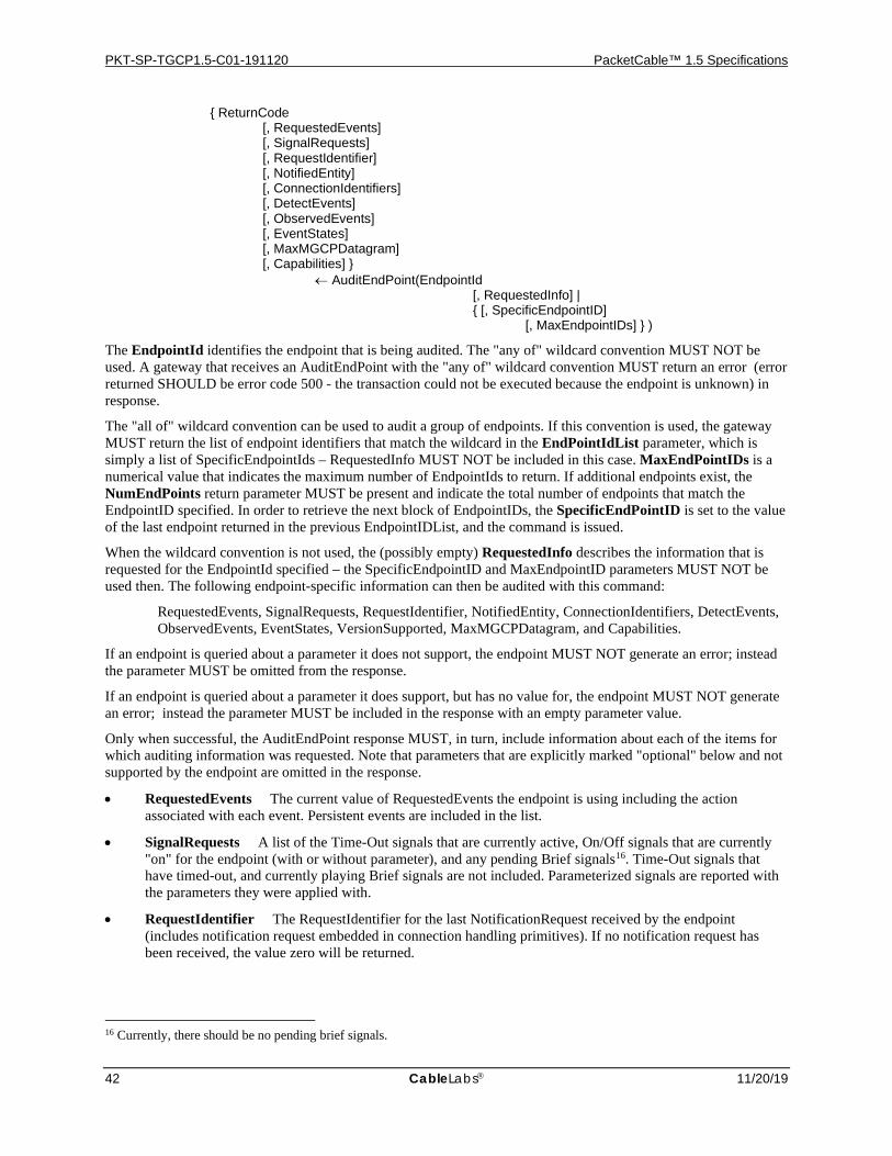
PKT-SP-TGCP1.5-C01-191120 PacketCable™ 1.5 Specifications
42 CableLabs 11/20/19
{ ReturnCode [, RequestedEvents] [, SignalRequests] [, RequestIdentifier] [, NotifiedEntity] [, ConnectionIdentifiers] [, DetectEvents] [, ObservedEvents] [, EventStates] [, MaxMGCPDatagram] [, Capabilities] } ← AuditEndPoint(EndpointId [, RequestedInfo] | { [, SpecificEndpointID] [, MaxEndpointIDs] } )
The EndpointId identifies the endpoint that is being audited. The "any of" wildcard convention MUST NOT be used. A gateway that receives an AuditEndPoint with the "any of" wildcard convention MUST return an error (error returned SHOULD be error code 500 - the transaction could not be executed because the endpoint is unknown) in response.
The "all of" wildcard convention can be used to audit a group of endpoints. If this convention is used, the gateway MUST return the list of endpoint identifiers that match the wildcard in the EndPointIdList parameter, which is simply a list of SpecificEndpointIds – RequestedInfo MUST NOT be included in this case. MaxEndPointIDs is a numerical value that indicates the maximum number of EndpointIds to return. If additional endpoints exist, the NumEndPoints return parameter MUST be present and indicate the total number of endpoints that match the EndpointID specified. In order to retrieve the next block of EndpointIDs, the SpecificEndPointID is set to the value of the last endpoint returned in the previous EndpointIDList, and the command is issued.
When the wildcard convention is not used, the (possibly empty) RequestedInfo describes the information that is requested for the EndpointId specified – the SpecificEndpointID and MaxEndpointID parameters MUST NOT be used then. The following endpoint-specific information can then be audited with this command:
RequestedEvents, SignalRequests, RequestIdentifier, NotifiedEntity, ConnectionIdentifiers, DetectEvents, ObservedEvents, EventStates, VersionSupported, MaxMGCPDatagram, and Capabilities.
If an endpoint is queried about a parameter it does not support, the endpoint MUST NOT generate an error; instead the parameter MUST be omitted from the response.
If an endpoint is queried about a parameter it does support, but has no value for, the endpoint MUST NOT generate an error; instead the parameter MUST be included in the response with an empty parameter value.
Only when successful, the AuditEndPoint response MUST, in turn, include information about each of the items for which auditing information was requested. Note that parameters that are explicitly marked "optional" below and not supported by the endpoint are omitted in the response.
• RequestedEvents The current value of RequestedEvents the endpoint is using including the action associated with each event. Persistent events are included in the list.
• SignalRequests A list of the Time-Out signals that are currently active, On/Off signals that are currently "on" for the endpoint (with or without parameter), and any pending Brief signals16. Time-Out signals that have timed-out, and currently playing Brief signals are not included. Parameterized signals are reported with the parameters they were applied with.
• RequestIdentifier The RequestIdentifier for the last NotificationRequest received by the endpoint (includes notification request embedded in connection handling primitives). If no notification request has been received, the value zero will be returned.
16 Currently, there should be no pending brief signals.
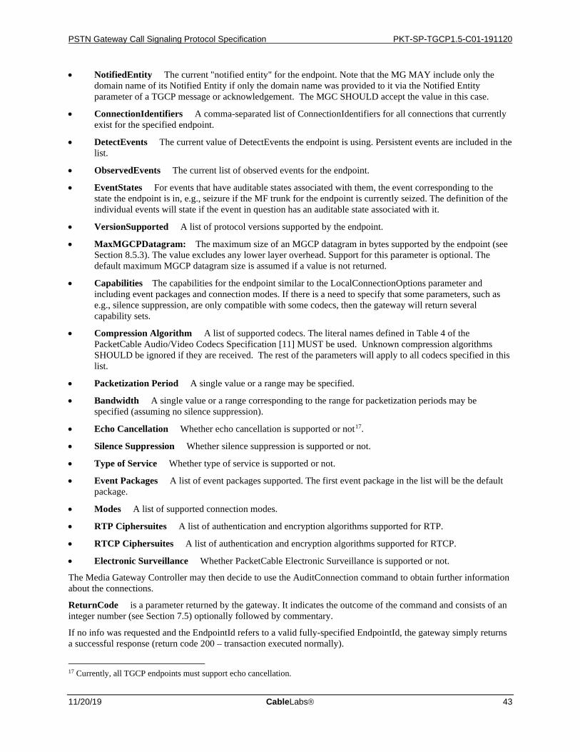
PSTN Gateway Call Signaling Protocol Specification PKT-SP-TGCP1.5-C01-191120
11/20/19 CableLabs 43
• NotifiedEntity The current "notified entity" for the endpoint. Note that the MG MAY include only the domain name of its Notified Entity if only the domain name was provided to it via the Notified Entity parameter of a TGCP message or acknowledgement. The MGC SHOULD accept the value in this case.
• ConnectionIdentifiers A comma-separated list of ConnectionIdentifiers for all connections that currently exist for the specified endpoint.
• DetectEvents The current value of DetectEvents the endpoint is using. Persistent events are included in the list.
• ObservedEvents The current list of observed events for the endpoint.
• EventStates For events that have auditable states associated with them, the event corresponding to the state the endpoint is in, e.g., seizure if the MF trunk for the endpoint is currently seized. The definition of the individual events will state if the event in question has an auditable state associated with it.
• VersionSupported A list of protocol versions supported by the endpoint.
• MaxMGCPDatagram: The maximum size of an MGCP datagram in bytes supported by the endpoint (see Section 8.5.3). The value excludes any lower layer overhead. Support for this parameter is optional. The default maximum MGCP datagram size is assumed if a value is not returned.
• Capabilities The capabilities for the endpoint similar to the LocalConnectionOptions parameter and including event packages and connection modes. If there is a need to specify that some parameters, such as e.g., silence suppression, are only compatible with some codecs, then the gateway will return several capability sets.
• Compression Algorithm A list of supported codecs. The literal names defined in Table 4 of the PacketCable Audio/Video Codecs Specification [11] MUST be used. Unknown compression algorithms SHOULD be ignored if they are received. The rest of the parameters will apply to all codecs specified in this list.
• Packetization Period A single value or a range may be specified.
• Bandwidth A single value or a range corresponding to the range for packetization periods may be specified (assuming no silence suppression).
• Echo Cancellation Whether echo cancellation is supported or not17.
• Silence Suppression Whether silence suppression is supported or not.
• Type of Service Whether type of service is supported or not.
• Event Packages A list of event packages supported. The first event package in the list will be the default package.
• Modes A list of supported connection modes.
• RTP Ciphersuites A list of authentication and encryption algorithms supported for RTP.
• RTCP Ciphersuites A list of authentication and encryption algorithms supported for RTCP.
• Electronic Surveillance Whether PacketCable Electronic Surveillance is supported or not.
The Media Gateway Controller may then decide to use the AuditConnection command to obtain further information about the connections.
ReturnCode is a parameter returned by the gateway. It indicates the outcome of the command and consists of an integer number (see Section 7.5) optionally followed by commentary.
If no info was requested and the EndpointId refers to a valid fully-specified EndpointId, the gateway simply returns a successful response (return code 200 – transaction executed normally).
17 Currently, all TGCP endpoints must support echo cancellation.
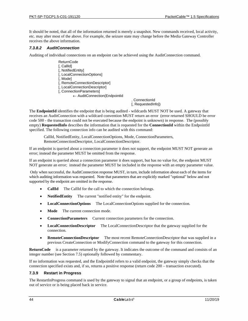
PKT-SP-TGCP1.5-C01-191120 PacketCable™ 1.5 Specifications
44 CableLabs 11/20/19
It should be noted, that all of the information returned is merely a snapshot. New commands received, local activity, etc. may alter most of the above. For example, the seizure state may change before the Media Gateway Controller receives the above information.
7.3.8.2 AuditConnection
Auditing of individual connections on an endpoint can be achieved using the AuditConnection command.
ReturnCode [, CallId] [, NotifiedEntity] [, LocalConnectionOptions] [, Mode] [, RemoteConnectionDescriptor] [, LocalConnectionDescriptor] [, ConnectionParameters] ← AuditConnection(EndpointId , ConnectionId [, RequestedInfo])
The EndpointId identifies the endpoint that is being audited - wildcards MUST NOT be used. A gateway that receives an AuditConnection with a wildcard convention MUST return an error (error returned SHOULD be error code 500 - the transaction could not be executed because the endpoint is unknown) in response. The (possibly empty) RequestedInfo describes the information that is requested for the ConnectionId within the EndpointId specified. The following connection info can be audited with this command:
CallId, NotifiedEntity, LocalConnectionOptions, Mode, ConnectionParameters, RemoteConnectionDescriptor, LocalConnectionDescriptor.
If an endpoint is queried about a connection parameter it does not support, the endpoint MUST NOT generate an error; instead the parameter MUST be omitted from the response.
If an endpoint is queried about a connection parameter it does support, but has no value for, the endpoint MUST NOT generate an error; instead the parameter MUST be included in the response with an empty parameter value.
Only when successful, the AuditConnection response MUST, in turn, include information about each of the items for which auditing information was requested. Note that parameters that are explicitly marked "optional" below and not supported by the endpoint are omitted in the response.
• CallId The CallId for the call to which the connection belongs.
• NotifiedEntity The current "notified entity" for the endpoint.
• LocalConnectionOptions The LocalConnectionOptions supplied for the connection.
• Mode The current connection mode.
• ConnectionParameters Current connection parameters for the connection.
• LocalConnectionDescriptor The LocalConnectionDescriptor that the gateway supplied for the connection.
• RemoteConnectionDescriptor The most recent RemoteConnectionDescriptor that was supplied in a previous CreateConnection or ModifyConnection command to the gateway for this connection.
ReturnCode is a parameter returned by the gateway. It indicates the outcome of the command and consists of an integer number (see Section 7.5) optionally followed by commentary.
If no information was requested, and the EndpointId refers to a valid endpoint, the gateway simply checks that the connection specified exists and, if so, returns a positive response (return code 200 – transaction executed).
7.3.9 Restart in Progress The RestartInProgress command is used by the gateway to signal that an endpoint, or a group of endpoints, is taken out of service or is being placed back in service.
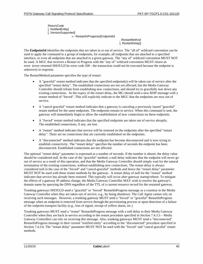
PSTN Gateway Call Signaling Protocol Specification PKT-SP-TGCP1.5-C01-191120
11/20/19 CableLabs 45
ReturnCode [, NotifiedEntity] [, VersionSupported] ← RestartInProgress(EndpointId , RestartMethod [, RestartDelay])
The EndpointId identifies the endpoints that are taken in or out of service. The "all of" wildcard convention can be used to apply the command to a group of endpoints, for example, all endpoints that are attached to a specified interface, or even all endpoints that are attached to a given gateway. The "any of" wildcard convention MUST NOT be used. A MGC that receives a Restart in Progress with the "any of" wildcard convention MUST return an error (error returned SHOULD be error code 500 - the transaction could not be executed because the endpoint is unknown) in response.
The RestartMethod parameter specifies the type of restart:
• A "graceful" restart method indicates that the specified endpoint(s) will be taken out of service after the specified "restart delay". The established connections are not yet affected, but the Media Gateway Controller should refrain from establishing new connections, and should try to gracefully tear down any existing connections. At the expiry of the restart delay, the MG should send a new RSIP message with a restart method of "forced". This will explicitly indicate to the MGC that the endpoints are now out of service.
• A "cancel-graceful" restart method indicates that a gateway is canceling a previously issued "graceful" restart method for the same endpoints. The endpoints remain in service. When this command is sent, the gateway will immediately begin to allow the establishment of new connections on these endpoints.
• A "forced" restart method indicates that the specified endpoints are taken out of service abruptly. The established connections, if any, are lost.
• A "restart" method indicates that service will be restored on the endpoints after the specified "restart delay". There are no connections that are currently established on the endpoints.
• A "disconnected" method indicates that the endpoint has become disconnected and is now trying to establish connectivity. The "restart delay" specifies the number of seconds the endpoint has been disconnected. Established connections are not affected.
The optional "restart delay" parameter is expressed as a number of seconds. If the number is absent, the delay value should be considered null. In the case of the "graceful" method, a null delay indicates that the endpoint will never go out of service as a result of this operation, and that the Media Gateway Controller should simply wait for the natural termination of the existing connections, without establishing new connections. The restart delay is always considered null in the case of the "forced" and "cancel-graceful" methods and hence the "restart delay" parameter MUST NOT be used with these restart methods by the gateway. A restart delay of null for the "restart" method indicates that service has already been restored. This typically will occur after gateway startup/reboot. To mitigate the effects of a gateway IP address change, the Media Gateway Controller MAY wish to resolve the gateway's domain name by querying the DNS regardless of the TTL of a current resource record for the restarted gateway.
Trunking gateways SHOULD send a "graceful" or "forced" RestartInProgress message as a courtesy to the Media Gateway Controller when they are taken out of service, e.g., by being shutdown. The Call Agent cannot rely on receiving such messages. However, a trunking gateway MUST send a "forced" or "graceful" RestartInProgress message when an endpoint is removed from service through the provisioning process or upon detection of a failure of the endpoint transport facility (e.g., loss of signal, receipt of yellow alarm, etc.)
Trunking gateways MUST send a "restart" RestartInProgress message with a null delay to their Media Gateway Controller when they are back in service according to the restart procedure specified in Section 7.4.3.5 – Media Gateway Controllers can rely on receiving this message. Also, trunking gateways MUST send a "disconnected" RestartInProgress message to their current "notified entity" according to the "disconnected" procedure specified in Section 7.4.3.6. The "restart delay" parameter MUST NOT be used with the "forced" and "cancel graceful" restart methods.
PKT-SP-TGCP1.5-C01-191120 PacketCable™ 1.5 Specifications
46 CableLabs 11/20/19
The RestartInProgress message will be sent to the current "notified entity" for the EndpointId in question. It is expected that a default Media Gateway Controller, i.e., "notified entity", has been provisioned for each endpoint so, after a reboot, the default Media Gateway Controller will be the "notified entity" for each endpoint. Trunking gateways MUST take full advantage of wild-carding to minimize the number of RestartInProgress messages generated when multiple endpoints in a gateway restart and the endpoints are managed by the same Media Gateway Controller.
ReturnCode is a parameter returned by the Media Gateway Controller. It indicates the outcome of the command and consists of an integer number (see Section 7.5) optionally followed by commentary.
A NotifiedEntity MAY additionally be returned with the response to the RestartInProgress from the Media Gateway Controller–this should normally only be done in response to "restart" or "disconnected" (see also Sections 7.4.3.5 and 7.4.3.6). If a NotifiedEntity parameter was included in the response returned, it specifies a new "notified entity" for the endpoint(s) – this operation SHOULD only be done with the response error code 521 (endpoint redirected). Note that the above behavior for returning a NotifiedEntity in the response is only defined for RestartInProgress responses and SHOULD NOT be done for responses to other commands. Any other behavior is undefined.
• If the response indicated success (return code 200 – transaction executed), the restart in question completed successfully, and the NotifiedEntity returned is the new "notified entity" for the endpoint(s).
• If the response from the Media Gateway Controller indicated an error code, the restart in question is not yet complete. If the response was 521 (endpoint redirected), then the response MUST include a NotifiedEntity parameter, which specifies the new "notified entity" for the endpoint(s) and MUST be used when retrying the restart in question (as a new transaction).
In the case of "restart" and "disconnected," the restart in question MUST be retried whenever the Media Gateway Controller returns a transient error code (4xx), whereas it SHOULD be retried for any other restartMethod. It is RECOMMENDED that any type of restart is terminated if a permanent error code (5xx) is returned, except for error code 521, as specified above.
Finally, a VersionSupported parameter with a list of supported versions may be returned if the response indicated version incompatibility (error code 528).
7.4 States, Failover, and Race Conditions In order to implement proper call signaling, the Media Gateway Controller must keep track of the state of the endpoint, and the gateway must make sure that events are properly notified to the Media Gateway Controller. Special conditions may exist when the gateway or the Media Gateway Controller are restarted: the gateway may need to be redirected to a new Media Gateway Controller during "failover" procedures; Similarly, the Media Gateway Controller may need to take special action when the gateway is taken offline, or restarted.
7.4.1 Recaps and Highlights As mentioned in Section 7.1.4, Media Gateway Controllers are identified by their domain name, and each endpoint has one, and only one, "notified entity" associated with it at any given point in time. In this section the areas of special importance to reliability and failover in MGCP are recapped and highlighted:
• A Media Gateway Controller is identified by its domain name, not its network addresses, and several network addresses can be associated with a domain name.
• An endpoint has one, and only one, Media Gateway Controller associated with it at any given point in time. The Media Gateway Controller associated with an endpoint is the current value of the "notified entity".
• The "notified entity" is initially set to a provisioned value. When commands with a NotifiedEntity parameter is received for the endpoint, including wild-carded endpoint-names, the "notified entity" is set to the value specified. If the "notified entity" for an endpoint is empty or has not been set explicitly18, the "notified entity" defaults to the source address of the last connection handling command or notification
18 This could for instance happen by specifying an empty NotifiedEntity parameter.
PSTN Gateway Call Signaling Protocol Specification PKT-SP-TGCP1.5-C01-191120
11/20/19 CableLabs 47
request received for the endpoint. In this case, the Media Gateway Controller will thus be identified by its network address, which SHOULD only be done on exceptional basis.
• Responses to commands are always sent to the source address of the command, regardless of the current "notified entity". When a Notify message needs to be piggy-backed with the response, the datagram is still sent to the source address of the new command received, regardless of the NotifiedEntity for any of the commands.
• When the "notified entity" refers to a domain name that resolves to multiple IP-addresses, endpoints are capable of switching between each of these addresses, however they cannot change the "notified entity" to another domain name on their own. A Media Gateway Controller can however instruct them to switch by providing them with a new "notified entity".
• If a Media Gateway Controller becomes unavailable, the endpoints managed by that Media Gateway Controller will eventually become "disconnected". The only way for these endpoints to become connected again is either for the failed Media Gateway Controller to become available again, or for another (backup) Media Gateway Controller to contact the affected endpoints with a new "notified entity".
• When another (backup) Media Gateway Controller has taken over control of a group of endpoints, it is assumed that the failed Media Gateway Controller will communicate and synchronize with the backup Media Gateway Controller in order to transfer control of the affected endpoints back to the original Media Gateway Controller, if so desired. Alternatively, the failed Media Gateway Controller could simply become the backup Media Gateway Controller now.
It should be noted, that handover conflict resolution between separate Media Gateway Controllers is not provided - we are relying strictly on the Media Gateway Controllers knowing what they are doing and communicating with each other (although AuditEndpoint can be used to learn about the current "notified entity").
7.4.2 Retransmission and Detection of Lost Associations The MGCP protocol is organized as a set of transactions, each of which is composed of a command and a response. The MGCP messages, being carried over UDP, may be subject to losses. In the absence of a timely response (see Section 8.4.4), commands are repeated. Gateways and Media Gateway Controllers MUST keep in memory a list of the responses that they sent to recent transactions (a list of all the responses they sent over the last Tthist seconds), and a list of the transactions that have not yet finished executing. The default value for Tthist is 30 seconds.
The transaction identifiers of incoming commands are first compared to the transaction identifiers of the recent responses. If a match is found, the gateway or Media Gateway Controller does not execute the transaction, but simply repeats the old response. If a match to a previously responded to transaction is not found, the transaction identifier of the incoming command is compared to the list of transactions that have not yet finished executing. If a match is found, the gateway or Media Gateway Controller does not execute the transaction; subsequent handling depends on the command in question. If it is a CreateConnection or ModifyConnection command, the gateway MUST send a provisional response. If it is any other command, it is simply ignored. In either case, a final response will be provided when the execution of the command is complete.
This repetition mechanism is used to guard against four types of possible errors:
• transmission errors, when, e.g., a packet is lost due to noise on a line or congestion in a queue,
• component failure, when, e.g., an interface for a Media Gateway Controller becomes unavailable,
• Media Gateway Controller failure, when, e.g., all interfaces for a Media Gateway Controller becomes unavailable,
• failover, when a new Media Gateway Controller is "taking over" transparently.
The elements should be able to derive from the past history an estimate of the packet loss rate. In a properly configured system, this loss rate should be very low, typically less than 1% on average. If a Media Gateway Controller or a gateway has to repeat a message more than a few times, it is very legitimate to assume that something else than a transmission error is occurring. For example, given a uniformly distributed loss rate of 1%, the probability that 5 consecutive transmission attempts fail is 1 in 100 billion, an event that should occur less than once
PKT-SP-TGCP1.5-C01-191120 PacketCable™ 1.5 Specifications
48 CableLabs 11/20/19
every 10 days for a Media Gateway Controller that processes 1,000 transactions per second. (Indeed, the number of repetitions that is considered excessive should be a function of the prevailing packet loss rate.) When errors are non-uniformly distributed, the consecutive failure probability can become somewhat higher. It should be noted, that the "suspicion threshold", which is identified as "Max1", is normally lower than the "disconnection threshold", which is identified as "Max2". Max2 MUST be set to a larger value than Max1.
The MGCP retransmission algorithm is illustrated in Figure 2 below and explained further in the following:
A classic retransmission algorithm would simply count the number of successive repetitions, and conclude that the association is broken after re-transmitting the packet an excessive number of times (typically between 7 and 11 times). In order to account for the possibility of an undetected or in-progress "failover", we modify the classic algorithm as shown in Figure 2 below:
• The gateway MUST always check for the presence of a new Media Gateway Controller. It can be noticed by:
• receiving a command where the NotifiedEntity points to a new Media Gateway Controller, or
• receiving a redirection response pointing to a new Media Gateway Controller.
• If a new Media Gateway Controller is detected, the gateway MUST direct retransmissions of any outstanding commands for the endpoint(s) redirected to that new Media Gateway Controller. Responses to new or old commands are still transmitted to the source address of the command.
• Prior to any retransmission, it is checked that the time elapsed since the sending of the initial datagram is no greater than Tsmax. If more than Tsmax time has elapsed, then retransmissions MUST cease. If more than 2*Tthist has elapsed, then the endpoint becomes disconnected.
• If the number of retransmissions to this Media Gateway Controller equals "Max1", the gateway MAY actively query the name server in order to detect the possible change of Media Gateway Controller interfaces, regardless of the Time To Live (TTL) associated with the DNS record.
• The gateway may have learned several IP addresses for the Media Gateway Controller. If the number of retransmissions for this IP address is greater than or equal to "Max1" and less than "Max2", and there are more IP addresses that have not been tried, then the gateway MUST direct the retransmissions to the remaining alternate addresses in its local list. Also, receipt of explicit network notifications such as, e.g., ICMP network, host, protocol, or port unreachable SHOULD lead the gateway to try alternate addresses (with due consideration to possible security issues).
• If there are no more interfaces to try, and the number of repetitions for this address is Max2, then the gateway SHOULD contact the DNS one more time to see if any other interfaces have become available. If there still are no more interfaces to try, then retransmissions MUST cease. If more than 2*Tthist has elapsed, then the endpoint becomes disconnected.
• Once an endpoint becomes disconnected, subsequent processing depends on whether the loss of association was detected by the gateway or Media Gateway Controller, as follows:
• The gateway MUST initiate the "disconnected" procedure as specified in Section 7.4.3.6.
• The Media Gateway Controller MUST NOT attempt to use the endpoint for any new calls until connectivity has been restored. Furthermore, the Media Gateway Controller MUST implement an algorithm to detect when connectivity with the endpoint is subsequently restored (e.g., on receiving a response to a periodic Audit Endpoint command). When connectivity to the endpoint is restored, and if no other condition exists which prevents the endpoint from supporting calls, the MGC MUST ensure that the endpoint can be used for new calls without requiring any manual intervention.
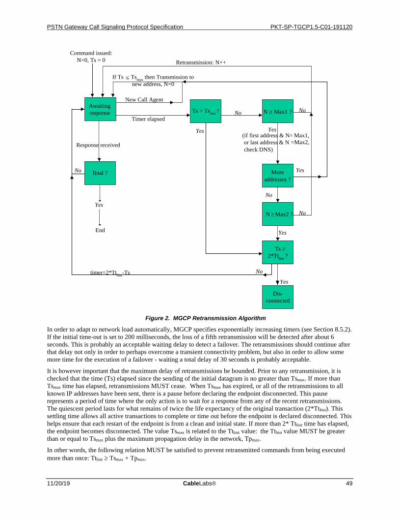
PSTN Gateway Call Signaling Protocol Specification PKT-SP-TGCP1.5-C01-191120
11/20/19 CableLabs 49
Command issued:N=0, Ts = 0
Awaitingresponse N ≥ Max1 ?
Moreaddresses ?
N Max2 ?
If Ts Tsmax then Transmission tonew address, N=0
Yes(if first address & N= Max1,or last address & N =Max2,check DNS)
No
Yes
Ts2*Tthist ?
No
New Call Agent
Timer elapsed
Retransmission: N++
No
Yes
Ts > Tsmax ?
Response received
No
Yes
final ?
Yes
End
No
Dis-connected
Yes
No
>
≥
≥
timer=2*Tthist-Ts
Figure 2. MGCP Retransmission Algorithm
In order to adapt to network load automatically, MGCP specifies exponentially increasing timers (see Section 8.5.2). If the initial time-out is set to 200 milliseconds, the loss of a fifth retransmission will be detected after about 6 seconds. This is probably an acceptable waiting delay to detect a failover. The retransmissions should continue after that delay not only in order to perhaps overcome a transient connectivity problem, but also in order to allow some more time for the execution of a failover - waiting a total delay of 30 seconds is probably acceptable.
It is however important that the maximum delay of retransmissions be bounded. Prior to any retransmission, it is checked that the time (Ts) elapsed since the sending of the initial datagram is no greater than Tsmax. If more than Tsmax time has elapsed, retransmissions MUST cease. When Tsmax has expired, or all of the retransmissions to all known IP addresses have been sent, there is a pause before declaring the endpoint disconnected. This pause represents a period of time where the only action is to wait for a response from any of the recent retransmissions. The quiescent period lasts for what remains of twice the life expectancy of the original transaction (2*Tthist). This settling time allows all active transactions to complete or time out before the endpoint is declared disconnected. This helps ensure that each restart of the endpoint is from a clean and initial state. If more than 2* Tthist time has elapsed, the endpoint becomes disconnected. The value Tsmax is related to the Tthist value: the Tthist value MUST be greater than or equal to Tsmax plus the maximum propagation delay in the network, Tpmax.
In other words, the following relation MUST be satisfied to prevent retransmitted commands from being executed more than once: Tthist ≥ Tsmax + Tpmax.
PKT-SP-TGCP1.5-C01-191120 PacketCable™ 1.5 Specifications
50 CableLabs 11/20/19
The default value for Tsmax is 20 seconds. Thus, if the assumed maximum propagation delay is 10 seconds, then responses to old transactions must be kept for a period of at least 30 seconds. The importance of having the sender and receiver agree on these values cannot be overstated.
The default value for Max1 is 5 retransmissions and the default value for Max2 is 7 retransmissions. Both of these values may be altered by the provisioning process.
Furthermore, the provisioning process MUST be able to disable one or both of the Max1 and Max2 DNS queries.
7.4.3 Race Conditions This section describes how MGCP deals with race conditions.
First of all, MGCP deals with race conditions through the notion of a "quarantine list" that quarantines events and through explicit detection of desynchronization, e.g., for mismatched seizure-state due to glare for an endpoint.
Secondly, MGCP does not assume that the transport mechanism will maintain the order of commands and responses. This may cause race conditions that may be obviated through a proper behavior of the Media Gateway Controller by a proper ordering of commands.
Finally, in some cases, many gateways may decide to restart operation at the same time. This may occur, for example, if an area loses power or transmission capability during an earthquake or an ice storm. When power and transmission capability are reestablished, many gateways may decide to send RestartInProgress commands simultaneously, which could lead to very unstable operation if not carefully controlled.
7.4.3.1 Quarantine list
MGCP controlled gateways will receive notification requests that ask them to watch for a list of events. The protocol elements that determine the handling of these events are the "Requested Events" list, and the "Detect Events" list.
When the endpoint is initialized, the requested events list only consists of persistent events for the endpoint. After reception of a command, the gateway starts observing the endpoint for occurrences of the events mentioned in the list, including persistent events.
The events are examined as they occur. The action that follows is determined by the "action" parameter associated to the event in the list of requested events. The events that are defined as "accumulate" are accumulated in a list of observed events. This will go on until one event is encountered that triggers a Notify command which will be sent to the "notified entity".
The gateway, at this point, will transmit the Notify command and will place the endpoint in a "notification state". As long as the endpoint is in this "notification state", the events that are detected on the endpoint are stored in a "quarantine" buffer for later processing. The events are, in a sense, "quarantined". The events detected are the events specified by the union of the RequestedEvents parameter and the most recently received DetectEvents parameter or, in case no DetectEvents parameter has been received, the events that are referred to in the RequestedEvents. Persistent events are detected as well.
The endpoint exits the "notification state" when the response to the Notify command is received.19 The Notify command may be retransmitted in the "notification state", as specified in Section 7.4.2.
If the endpoint is or has become disconnected (see Section 7.4.2) during this, a response to the Notify command will never be received. The Notify command is then lost and hence no longer considered pending, yet the endpoint is still in the "notification state." Should this occur, completion of the disconnected procedure specified in Section 7.4.3.6 shall then lead the endpoint to exit the "notification state."
When the endpoint exits the "notification state" it resets the list of observed events of the endpoint to a null value. Following that point, the behavior of the gateway depends on the value of the QuarantineHandling parameter in the triggering NotificationRequest command:
If a QuarantineHandling parameter of "step" was specified by the Call Agent/Media Gateway Controller or if no value was specified, then the gateway will use "lockstep mode", which implies that the gateway MUST receive a new NotificationRequest command after it has sent a Notify command. Until this happens, the endpoint is in a
19 It should be noted, that the Notify action cannot be combined with an Embedded NotificationRequest.
PSTN Gateway Call Signaling Protocol Specification PKT-SP-TGCP1.5-C01-191120
11/20/19 CableLabs 51
"lockstep state", and events that occur and are to be detected are simply stored in the quarantine buffer. The events to be quarantined are the same as in the "notification state". Once the new NotificationRequest is received and executed successfully, the endpoint exits the "lockstep state".
If a QuarantineHandling parameter of "loop" was specified by the Call Agent/Media Gateway Controller (i.e., "loop" mode), it will proceed as follows. When the gateway exits the "notification state", it resets the list of observed events of the endpoint to a null value and starts processing the list of quarantined events, using the already received list of requested events. When processing these events, the gateway may encounter an event, which triggers a Notify command to be sent. If that is the case, the gateway can adopt one of the two following behaviors:
• it can immediately transmit a Notify command that will report all events that were accumulated in the list of observed events until the triggering event, included, leaving the unprocessed events in the quarantine buffer,
• it can attempt to empty the quarantine buffer and transmit a single Notify command reporting several sets of events. The events that follow the last triggering event MUST be left in the quarantine buffer.
If the gateway transmits a Notify command, the endpoint will reenter and remain in the "notification state" until the acknowledgement is received (as described above). If the gateway does not find a quarantined event that triggers a Notify command, it places the endpoint in a normal state. Events are then processed as they come, in exactly the same way as if a Notification Request command had just been received.
A gateway can receive at any time a new NotificationRequest command for the endpoint, including the case where the endpoint is disconnected, which will also have the effect of taking the endpoint out of the "notification state" assuming the NotificationRequest executes successfully. Activating an embedded NotificationRequest is here viewed as receiving a new NotificationRequest as well, except that the current list of ObservedEvents remains unmodified rather than being processed again.
When a new NotificationRequest is received in the "notification state," the gateway SHOULD attempt to deliver the pending Notify (note that a Notify that was lost due to being disconnected, is no longer considered pending) prior to a successful response to the new NotificationRequest. It does so by using the "piggy-backing" functionality of the protocol and placing the messages (commands and responses) to be sent in order with the oldest message first. The messages will then be sent in a single packet to the source of the new NotificationRequest, regardless of the source and "notified entity" for the old and new command. The steps involved are the following:
1. The gateway builds a message that carries in a single packet a repetition of the old outstanding Notify command and the response to the new NotificationRequest command.
2. The endpoint is then taken out of the "notification state" without waiting for the response to the Notify command.
3. A copy of the outstanding Notify command is kept until a response is received. If a time-out occurs, the Notify will be repeated, in a packet that will also carry a repetition of the response to the NotificationRequest.
• If the packet carrying the response to the NotificationRequest is lost, the Call Agent/Media Gateway Controller will retransmit the NotificationRequest. The gateway will reply to this repetition by retransmitting in a single packet the outstanding Notify command and the response to the NotificationRequest – this datagram will be sent to the source of the NotificationRequest
• Notify's for a given endpoint MUST be delivered in-order. If the gateway has to transmit a new Notify before a response to the previous Notify is received, it constructs a packet that piggy-backs a repetition of the old Notify, a repetition of the response to the last NotificationRequest, and the new Notify – this datagram will be sent to current "notified entity".
After receiving a NotificationRequest command, the "requested events" list is replaced by the newly received parameters. Furthermore, when the NotificationRequest was received in the "notification state", the list of "observed events" is reset to a null value. The subsequent behavior is then conditioned by the value of the QuarantineHandling parameter. The parameter may specify that quarantined events, and observed events (which in this case is an empty list), are to be discarded, in which case all quarantined and observed events are discarded. If the parameter specifies that the quarantined and observed events should be processed, the gateway will start processing the list of quarantined and observed events, using the newly received list of "requested events". When processing these events, the gateway may encounter an event, which triggers a Notify command to be sent. If that is the case, the gateway

PKT-SP-TGCP1.5-C01-191120 PacketCable™ 1.5 Specifications
52 CableLabs 11/20/19
will immediately transmit a Notify command that will report all events that were accumulated in the list of "observed events" up until and including the triggering event, leaving the unprocessed events in the quarantine buffer. The endpoint then enters the "notification state" again.
A new notification request may be received while the gateway has accumulated events according to the previous notification requests, but has not yet detected any notification-triggering events. The handling of not-yet-notified events is determined, as with the quarantined events, by the quarantine handling parameters:
• If the quarantine-handling parameter specifies that quarantined events shall be ignored, the observed events list is simply reset.
• If the quarantine-handling parameter specifies that quarantined events shall be processed, the observed event list is transferred to the quarantined event list. The observed event list is then reset, and the quarantined event list is processed. The only exception is the activation of an embedded Notification Request. In this case the observed event list remains unmodified rather than being processed again.
The above procedure applies to all forms of notification requests, regardless of whether they are part of a connection handling command or provided as a NotificationRequest command. Connection handling commands that do not include a notification request are neither affected by nor do they affect the above procedure.
Figure 3 below illustrates the procedure specified above assuming all transactions execute successfully:
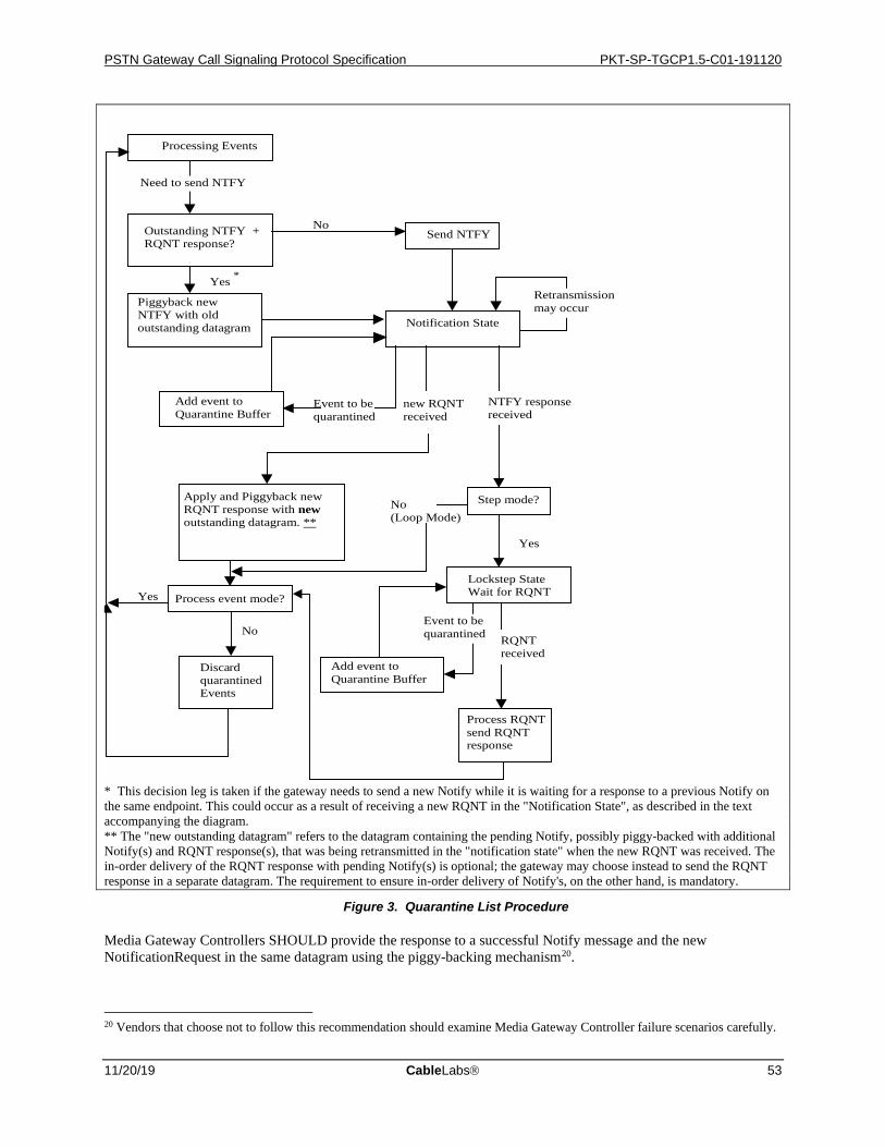
PSTN Gateway Call Signaling Protocol Specification PKT-SP-TGCP1.5-C01-191120
11/20/19 CableLabs 53
Yes
No (Loop Mode)
new RQNT received
Yes *
No
Processing Events
Outstanding NTFY + RQNT response?
Piggyback new NTFY with old outstanding datagram
Notification State
Send NTFY
Event to be quarantined
Add event to Quarantine Buffer
NTFY response received
Step mode?
Lockstep State Wait for RQNT
Process RQNT d send RQNT
response
Disca rd quarantined Events
Yes
No RQNT received
Retransmission may occur
Process event mode?
Event to be quarantined
Add event to Quarantine Buffer
Need to send NTFY
Apply and Piggyback new RQNT response with new outstanding datagram. **
* This decision leg is taken if the gateway needs to send a new Notify while it is waiting for a response to a previous Notify on the same endpoint. This could occur as a result of receiving a new RQNT in the "Notification State", as described in the text accompanying the diagram. ** The "new outstanding datagram" refers to the datagram containing the pending Notify, possibly piggy-backed with additional Notify(s) and RQNT response(s), that was being retransmitted in the "notification state" when the new RQNT was received. The in-order delivery of the RQNT response with pending Notify(s) is optional; the gateway may choose instead to send the RQNT response in a separate datagram. The requirement to ensure in-order delivery of Notify's, on the other hand, is mandatory.
Figure 3. Quarantine List Procedure
Media Gateway Controllers SHOULD provide the response to a successful Notify message and the new NotificationRequest in the same datagram using the piggy-backing mechanism20.
20 Vendors that choose not to follow this recommendation should examine Media Gateway Controller failure scenarios carefully.
PKT-SP-TGCP1.5-C01-191120 PacketCable™ 1.5 Specifications
54 CableLabs 11/20/19
7.4.3.2 Explicit detection
A key element of the state of several endpoints is the seizure state of a circuit. Although seizure-state changing events are persistent in TGCP, race conditions and state mismatch may still occur, for example when a circuit is seized while the Media Gateway Controller is in the process of requesting the gateway to look for seizure (the "glare" condition well known in telephony – this is however primarily an issue for two-way CAS trunks, which are not supported in this version of the specification).
To avoid this race condition, the gateway MUST check the condition of the endpoint before responding to a NotificationRequest. Specifically, it MUST return an error:
1. If the gateway is requested to notify a "seizure"21 transition while the circuit is already seized (error code 401 – circuit seized),
2. If the gateway is requested to notify an "unseize"22 condition while the circuit is not seized (error code 402 – circuit not seized).
Additionally, individual signal definitions can specify that a signal will only operate under certain conditions, e.g., MF operator ringback may only be possible if the circuit is already seized. If such prerequisites exist for a given signal, the gateway MUST return the error specified in the signal definition if the prerequisite is not met.
It should be noted, that the condition check is performed at the time the notification request is received, whereas the actual event that caused the current condition may have either been reported, or ignored earlier, or it may currently be quarantined.
The other state variables of the gateway, such as the list of requested events or list of requested signals, are entirely replaced after each successful NotificationRequest, which prevents any long term discrepancy between the Media Gateway Controller and the gateway.
When a NotificationRequest is unsuccessful, whether it is included in a connection-handling command or not, the gateway will simply continue as if the command had never been received, although an error is returned. As all other transactions, the NotificationRequest MUST operate as an atomic transaction, thus any changes initiated as a result of the command MUST be reverted.
When the Media Gateway Controller receives an error response indicating that a NotificationRequest was unsuccessful, it MUST take action to ensure that any events quarantined by the endpoint are processed or discarded, and that the endpoint is returned to a normal operating mode where newly requested events are reported as they occur. For example, say the Media Gateway Controller receives an error code "401 - endpoint already seized" response to a NotificationRequest requesting detection of the "MT/sup" signal. At this point the Media Gateway Controller should assume that the NotificationRequest had no effect on the endpoint, and that the endpoint is in the same state that it was prior receiving the command. If the endpoint was quarantining events in the "lockstep" state prior to receiving the NotificationRequest, then it will still be quarantining events in the "lockstep" state after sending the "401" error response. To ensure that the endpoint is not left in a state where it is permanently quarantining events, the Media Gateway Controller should send a new NotificationRequest with a different (possibly empty) set of requested events to transition the endpoint out of the "lockstep" state and into the normal mode where it can report new events.
Another race condition can occur when a Notify is issued shortly before the reception by the gateway of a NotificationRequest. The RequestIdentifier is used to correlate Notify commands with NotificationRequest (includes notification request embedded in connection handling primitives) commands thereby enabling the Media Gateway Controller to determine if the Notify command was generated before or after the gateway received the new NotificationRequest.
7.4.3.3 Transactional Semantics
As the potential transaction completion times increases, e.g., due to external resource reservations, a careful definition of the transactional semantics becomes increasingly important. In particular the issue of race conditions, specifically as it relates to seizure-state must be defined carefully.
21 For instance by requesting the "sup" event on an MF Terminating BLV/OI trunk with a call already in progress. 22 For instance by requesting the "rel" event on an MF Operator Services trunk without any call in progress.
PSTN Gateway Call Signaling Protocol Specification PKT-SP-TGCP1.5-C01-191120
11/20/19 CableLabs 55
An important point to consider is, that the seizure-state may in fact change between the time a transaction is initiated and the time it completes. More generally, we may say that the successful completion of a transaction depends on one or more pre-conditions where one or more of the pre-conditions may change dynamically during the execution of the transaction.
The simplest semantics for this is simply to require that all pre-conditions MUST be met from the time the transaction is initiated until the transaction completes. Thus, if any of the preconditions change during the execution of the transaction, the transaction MUST fail. Furthermore, as soon as the transaction is initiated, all new events are quarantined. When the outcome of the transaction is known, all quarantined events are then processed.
As an example, consider a transaction that includes a request for the "seizure" event. When the transaction is initiated the circuit is "not seized" and this pre-condition is therefore met. If the seizure-state changes to "seized" before the transaction completes, the pre-condition is no longer met, and the transaction therefore immediately fails. The "seizure" event will now be stored in the "quarantine" buffer which then gets processed.
7.4.3.4 Ordering of commands and treatment of disorder
MGCP does not mandate that the underlying transport protocol guarantees the sequencing of commands sent to a gateway or an endpoint. This property tends to maximize the timeliness of actions, but it has a few drawbacks. For example:
• Notify commands may be delayed and arrive to the Media Gateway Controller after the transmission of a new Notification Request command,
• If a new NotificationRequest is transmitted before a response to a previous one is received, there is no guarantee that the previous one will not be received in second position.
Media Gateway Controllers and gateways that want to guarantee consistent operation of the endpoints can use the rules specified:
1. When a gateway handles several endpoints, commands pertaining to the different endpoints can be sent in parallel, for example following a model where each endpoint is controlled by its own process or its own thread.
2. When several connections are created on the same endpoint, commands pertaining to different connections can be sent in parallel.
3. On a given connection, there should normally be only one outstanding command (create or modify). However, a DeleteConnection command can be issued at any time. In consequence, a gateway may sometimes receive a ModifyConnection command that applies to a previously deleted connection. Such commands MUST be ignored, and an error returned (error code 515 – incorrect connection-id).
4. On a given endpoint, there should normally be only one outstanding NotificationRequest command at any time. The RequestId parameter is used to correlate Notify commands with the triggering NotificationRequest.
5. In some cases, an implicitly or explicitly wild-carded DeleteConnection command that applies to a group of endpoints can step in front of a pending CreateConnection command. The Media Gateway Controller should individually delete all connections whose completion was pending at the time of the global DeleteConnection command. Also, new CreateConnection commands for endpoints named by the wild-carding should not be sent until a response to the wild-carded DeleteConnection command is received.
6. When commands are embedded within each other, sequencing requirements for all commands MUST be adhered to. For example, a CreateConnection command with a notification request in it must adhere to the sequencing requirements for CreateConnection and NotificationRequest at the same time.
7. AuditEndpoint and AuditConnection is not subject to any sequencing.
8. RestartInProgress must always be the first command sent by an endpoint as defined by the restart procedure (see Section 7.4.3.5). Any other command or response must be delivered after this RestartInProgress command (piggy-backing allowed).
9. When multiple messages are piggy-backed in a single packet, the messages are always processed in order.
Those of the above rules that specify gateway behavior MUST be adhered to by trunking gateways, however, the trunking gateway MUST NOT make any assumptions as to whether Media Gateway Controllers follow the rules or
PKT-SP-TGCP1.5-C01-191120 PacketCable™ 1.5 Specifications
56 CableLabs 11/20/19
not Consequently gateways MUST always respond to commands, regardless of whether they adhere to the above rules or not.
To ensure consistent operation, trunking gateways SHOULD behave as specified below when one or more of the above rules are not followed:
• Where a single outstanding command is expected (ModifyConnection, NotificationRequest), but the same command is received in a new transaction before the old finishes executing, the gateway SHOULD fail the previous command. This includes the case where one or more of the commands were encapsulated. The use of error code 407 (transaction aborted) is RECOMMENDED.
• If a ModifyConnection command is received for a pending CreateConnection command, the ModifyConnection command SHOULD simply be rejected. The use of error code 400 (transient error) is RECOMMENDED. Note that this situation constitutes a Media Gateway Controller programming error.
Note, that where reception of a new command leads to aborting an old command, the old command SHOULD be aborted regardless of whether the new command succeeds or not. For example, if a ModifyConnection command is aborted by a DeleteConnection command which itself fails due to an encapsulated NotificationRequest, the ModifyConnection command is still aborted.
7.4.3.5 Fighting the restart avalanche
Suppose that a large number of gateways are powered on simultaneously. If they were to all initiate a RestartInProgress transaction, the Media Gateway Controller would very likely be swamped, leading to message losses and network congestion during the critical period of service restoration. In order to prevent such avalanches, the following behavior MUST be followed:
1. When a gateway is powered on, or when all or a subset of the gateway's endpoints are returned to service, the gateway initiates a restart timer to a random value, uniformly distributed between 0 and a provisionable maximum waiting delay (MWD), e.g., 360 seconds (see below).Care MUST be taken to avoid synchronicity of the random number generation between multiple gateways that would use the same algorithm.
2. The gateway then waits for either the end of this timer, the reception of a command from the Media Gateway Controller, or the detection of a local circuit activity, such as for example an seizure transition on a trunking gateway. A pre-existing seizure condition results in the generation of a seizure event.
3. When the restart timer elapses, when a command is received, or when an activity or pre-existing seizure condition is detected, the gateway initiates the restart procedure.
The restart procedure simply states that the endpoint MUST send a RestartInProgress command to the Media Gateway Controller informing it about the restart and furthermore guarantee that the first message (command or response) that the Media Gateway Controller sees from this endpoint MUST be this RestartInProgress command. During each initiation of "disconnected" procedure, the command MUST observe the normal retransmission and transaction identifiers requirements (see Section 7.4.2).
The endpoint MUST take full advantage of piggy-backing in achieving this. For example, if a circuit seizure activity occurs prior to the restart timer expiring, a packet containing the RestartInProgress command, and with a piggy-backed Notify command for the seizure event will be generated. In the case where the restart timer expires without any other activity, the gateway simply sends a RestartInProgress message.
The restart procedure is complete once a success response has been received. If an error response is received, the subsequent behavior depends on the error code in question:
• If the error code indicates a transient error (4xx), then the restart procedure MUST be initiated again (as a new transaction).
• If the error code is 521, then the endpoint is redirected, and the restart procedure MUST be initiated again (as a new transaction). The 521 response should have included a NotifiedEntity which then is the "notified entity" towards which the restart is initiated.
PSTN Gateway Call Signaling Protocol Specification PKT-SP-TGCP1.5-C01-191120
11/20/19 CableLabs 57
• If the error is any other permanent error (5xx), then it is RECOMMENDED that the endpoint no longer initiates the restart procedure on its own (until rebooted) unless otherwise specified. If a command is received, the endpoint MUST initiate the restart procedure again.
Note that if the RestartInProgress is piggy-backed with the response (R) to a command received while restarting, then retransmission of the RestartInProgress does not require piggy-backing of the response R. However, while the endpoint is restarting, a resend of the response R does require the RestartInProgress to be piggy-backed to ensure in-order delivery of the two.
Should the endpoint enter the "disconnected" state while carrying out the restart procedure, then the disconnected procedure specified in Section 7.4.3.6 MUST be carried out, and a "disconnected" message is sent during the procedure.
It is expected that each endpoint in a gateway will have a provisionable Media Gateway Controller, i.e., "notified entity", to direct the initial restart message towards. When the collection of endpoints in a gateway is managed by more than one Media Gateway Controller, the above procedure must be performed for each collection of endpoints managed by a given Media Gateway Controller. The gateway MUST take full advantage of wild-carding to minimize the number of RestartInProgress messages generated when multiple endpoints in a gateway restart and the endpoints are managed by the same Media Gateway Controller.
The value of MWD is a configuration parameter that depends on the type of the gateway. The following reasoning can be used to determine the value of this delay on a gateway.
Media Gateway Controllers are typically dimensioned to handle the peak hour traffic load, during which, on average, 60% of the trunks will be busy serving calls whose average duration is typically 3 minutes. The processing of a call typically involves 5 to 6 transactions between each endpoint and the Media Gateway Controller. This simple calculation shows that the Media Gateway Controller is expected to handle 5 to 6 transactions for each endpoint, every 5 minutes on average, or, to put it otherwise, about one transaction per endpoint per minute. This suggests that a reasonable value of MWD would be 2 minutes per endpoint. When the value of MWD is set for the gateway, the value should be inversely proportional to the number of endpoints that are being restarted. For example, MWD should be set to 5 seconds for a gateway that handles a T1 line, or to 180 milliseconds for a gateway that handles a T3 line.
7.4.3.6 Disconnected Endpoints
In addition to the restart procedure, trunking gateways also have a "disconnected" procedure, which is initiated when an endpoint becomes "disconnected" as described in Section 7.4.2. It should here be noted, that endpoints can only become disconnected when they attempt to communicate with the Media Gateway Controller. The following steps are followed by an endpoint that becomes "disconnected":
1. A "disconnected" timer is initialized to a random value, uniformly distributed between 0 and a provisionable "disconnected" initial waiting delay (Tdinit), e.g., 15 seconds. Care MUST be taken to avoid synchronicity of the random number generation between multiple gateways and endpoints that would use the same algorithm.
2. The gateway then waits for either the end of this timer, the reception of a command from the Media Gateway Controller, or the detection of a local circuit activity for the endpoint, such as for example a seizure transition.
3. When the "disconnected" timer elapses, when a command is received, or when a local circuit activity is detected, the gateway MUST initiate the "disconnected" procedure with a new transaction ID for the endpoint. In the case of local circuit activity, a provisionable "disconnected" minimum waiting delay (Tdmin) must furthermore have elapsed since the gateway became disconnected or the last time it ended the "disconnected" procedure in order to limit the rate at which the procedure is performed.
4. If the "disconnected" procedure still left the endpoint disconnected, the "disconnected" timer is then doubled, subject to a provisionable "disconnected" maximum waiting delay (Tdmax), e.g., 600 seconds, and the gateway proceeds with step 2 again.
The "disconnected" procedure is similar to the restart procedure in that it now simply states that the endpoint MUST send a RestartInProgress command to the Media Gateway Controller informing it that the endpoint was disconnected and furthermore guarantee that the first message (command or response) that the Media Gateway Controller now sees from this endpoint MUST be this RestartInProgress command. During each initiation of
PKT-SP-TGCP1.5-C01-191120 PacketCable™ 1.5 Specifications
58 CableLabs 11/20/19
"disconnected" procedure, the command MUST observe the normal retransmission and transaction identifiers requirements (see Section 7.4.2). The endpoint MUST take full advantage of piggy-backing in achieving this.
On receiving a RestartInProgress message containing a restart method of "disconnected" the Media Gateway Controller MUST take action to ensure that any events quarantined by the endpoint are processed or discarded, and that the endpoint is returned to a normal operating mode where newly requested events are reported as they occur. The Media Gateway Controller SHOULD send a NotificationRequest containing a Quarantine-Handling parameter set to "discard" in this case. The Media Gateway Controller may also decide to perform one or more of the following: audit the endpoint, clear all connections for the endpoint, or send a NotificationRequest asking the endpoint to process quarantined events (see Section 7.4.3.7).
A disconnected endpoint may wish to send a command (besides RestartInProgress) while it is disconnected. Doing so will only succeed once the Media Gateway Controller is reachable again, which raises the question of what to do with such a command meanwhile. At one extreme, the endpoint could drop the command right away, however that would not work very well when the Media Gateway Controller was in fact available, but the endpoint had not yet completed the "disconnected" procedure (consider for example the case where a NotificationRequest was just received which immediately resulted in a Notify being generated.) To prevent such scenarios, disconnected endpoints MUST NOT blindly drop new commands to be sent for a period of Tsmax seconds after they receive a non-audit command.
One way of satisfying this requirement is to employ a temporary buffering of commands to be sent, however in doing so, the endpoint must ensure that it:
• does not build up a long queue of commands to be sent,
• does not swamp the Media Gateway Controller by rapidly sending too many commands once it is connected again.
Buffering commands for Tsmax seconds and, once the endpoint is connected again, limiting the rate at which buffered commands are sent to one outstanding command per endpoint is considered safe. If the endpoint is not connected within Tsmax seconds, but a "disconnected" procedure is initiated within Tsmax seconds, the endpoint MAY piggy-back the buffered command(s) with that RestartInProgress. Note that once a command has been sent, regardless of whether it was buffered initially, or piggy-backed earlier, retransmission of that command MUST cease Tsmax seconds after the initial send as described in Section 7.4.2.
The disconnected procedure is complete once a success response has been received. Error responses are handled similarly to the restart procedure (Section 7.4.3.5). If the "disconnected" procedure is to be initiated again following an error response, the rate-limiting timer considerations specified above still apply.
Also note, that if the RestartInProgress is piggy-backed with the response (R) to a command received while being disconnected, then retransmission of the RestartInProgress does not require piggy-backing of the response R. However, while the endpoint is disconnected, resending the response R does require the RestartInProgress to be piggy-backed as well to ensure the in-order delivery of the two.
Note that if a disconnected procedure is already in progress when a command is received, the existing disconnect procedure MUST be terminated and a new procedure MUST be started. This is to support a possible Media Gateway Controller redirection.
Note also that a disconnected endpoint does not mean that the endpoint is in an "out-of-service" state. "Disconnected" is not a state of the endpoint's service availability, but rather an indication of the gateway's inability to communicate with its MGC.
This specification purposely does not specify any additional behavior for a disconnected endpoint. Vendors MAY for instance choose to provide silence, play reorder tone, or even enable a downloaded wav file to be played on affected endpoints.
The default value for Tdinit is 15 seconds, the default value for Tdmin, is 15 seconds, and the default value for Tdmax is 600 seconds.
PSTN Gateway Call Signaling Protocol Specification PKT-SP-TGCP1.5-C01-191120
11/20/19 CableLabs 59
7.4.3.7 Call Agent Handling of Disconnected Endpoints
When an endpoint is in the "disconnected" state it may accumulate a large number of events in the quarantine buffer. Also, a "disconnected" endpoint may autonomously delete established connections (say the gateway reboots). Therefore, when connectivity between a "disconnected" endpoint and its Call Agent is subsequently restored, the Call Agent MUST be prepared to deal with the following issues:
• The large number of Notify messages that may be generated by the endpoint if all events on the quarantine list are processed,
• The reception of old/stale events reported by the endpoint that no longer have any relevance. The quarantine buffer is a First-In-First-Out (FIFO) queue, where the oldest events are processed first and notified (if requested) to the Call Agent. The action taken by the Call Agent on receiving an old event may not be meaningful if the old event has been superseded by newer events (for example, an "MT/sup" event would no longer be relevant if the endpoint subsequently went on-hook),
• Connection state mismatch between the Call Agent and endpoint, where the Call Agent thinks the endpoint has one or more connections, but the endpoint in fact has no connections.
Call Agents are free to use any mechanism supported by the protocol to deal with the above issues. One way of achieving this is to do the following:
1. We define a new boolean variable called "disconnect-event-sync", which is maintained by the Call Agent for each of its endpoints. When set to true, this variable indicates that connectivity with a "disconnected" endpoint has recently been restored, but that event/signal synchronization has not yet been achieved. (Note, this variable is being introduced in order to describe Call Agent behavior, and is not intended to imply any particular implementation. The variable is not externally visible.)
a. As soon as the Call Agent learns that an endpoint is disconnected, it sets "disconnect-event-sync" to true. The "disconnected" procedure ensures, that the Call Agent will learn about the endpoint being disconnected by receiving a "disconnected" RestartInProgress message. When an endpoint receives a positive acknowledgement to the "disconnected" RSIP, it completes the "disconnected" procedure. At this point, the endpoint could immediately generate a Notify for a two reasons; to send a Notify command that was buffered while the endpoint was disconnected, or, if the endpoint was in the "notification" state and "loop" mode while disconnected, to report a Notify-triggering event on the quarantine list.
• If the endpoint operates in "step" mode, responding to the Notify will in itself not enable any further Notify messages to be generated (an additional NotificationRequest would be needed for that).
• However, if the endpoint operates in "loop" mode, then a response to the Notify will enable further Notify messages to be generated. As discussed above, this is sometimes undesirable as the events being reported may be old and a lot of events may have been quarantined, which in turn will result in a large number of Notify messages and subsequent NotificationRequest messages based on stale information.
b. As long as an endpoint has "disconnect-event-sync" set to true, the Call Agent should take action to ensure that the potentially large number of events on the quarantine list are either discarded, or processed in a controlled and orderly manner. This can be achieved in a number of ways:
• The Call Agent can send a single NotificationRequest specifying that all quarantined events are to be discarded. On receiving a positive acknowledgment to this command, or on receiving a Notify with the same RequestIdentifier, the Call Agent should set the "disconnect-event-sync" indicator to false, at which point regular event processing for the endpoint is resumed. The downside to this approach is that it will clear any events that have been accumulated, regardless of the number of events accumulated. In some cases, this may result in unnecessary service interruption. In order to address this, protocol extensions will be necessary.
• The Call Agent can send a NotificationRequest specifying that quarantined events are to be processed. If the endpoint is operating in "step" mode then it will report a single notify-triggering
PKT-SP-TGCP1.5-C01-191120 PacketCable™ 1.5 Specifications
60 CableLabs 11/20/19
event for each NotificationRequest received, whereas in the "loop" mode it can report multiple events under a single NotificationRequest.
• Since the information conveyed by the notified events may no longer be relevant, the Call Agent should not blindly process these events (for example, on being notified of an "MT/sup" origination event, the Call Agent should not automatically send a NotificationRequest to request notification of "MT/inf" digits). Instead, the Call Agent must synchronize its internal state data with the actual state of the endpoint. Since an endpoint performs signal/event glare processing against the current seizure state of the circuit, the Call Agent can discover the current seizure state based on the response to a NotificationRequest. For example, a "402 - circuit not seized" response to a NotificationRequest asking for detection of "MT/inf" implies that the MT trunk is currently not seized. The Call Agent may choose to ignore notified events that are incompatible with the current hook-switch state (ignore "MT/inf" report of digits if the trunk is not seized, for example). Once all events on the quarantine list have been processed, the Call Agent should set the "disconnect-event-sync" indicator to false. The Call Agent can safely assume that all quarantined events have been processed if a delay of duration Tthist has expired since the Call Agent last prompted the endpoint to process the next event (i.e., if a delay of duration Tthist has expired since the Call Agent sent the response to the previous Notify in the "loop" mode, or since the Call Agent received the last positive response to NotificationRequest in the "step" mode).
2. When endpoints become disconnected, connections created on that endpoint should be unaffected. However, it is always possible, that a connection can no longer be sustained by the endpoint and hence that it is deleted; this will result in a DeleteConnection command sent to the Call Agent. When the endpoint is disconnected, such a command may never make it to the Call Agent, in which case it will not learn about the deleted connection. Consequently, whenever a Call Agent learns that an endpoint is disconnected, it should audit the endpoint for the list of connections present on it.
7.5 Return Codes and Error Codes All MGCP commands receive a response. The response carries a return code that indicates the status of the command. The return code is an integer number, for which five value ranges have been defined:
• value 000 indicates a response acknowledgement23,
• values between 100 and 199 indicate a provisional response,
• values between 200 and 299 indicate a successful completion,
• values between 400 and 499 indicate a transient error,
• values between 500 and 599 indicate a permanent error.
The values that have been defined are listed in Table 3 below:
Table 3. Return Codes
Code Meaning
000 Response acknowledgement. 100 The transaction is currently being executed. An actual completion message will follow later. 200 The requested transaction was executed normally. 250 The connection(s) was deleted. 400 The transaction could not be executed, due to a transient error. 401 The phone is already off hook or circuit already seized. 402 The phone is already on hook or circuit not seized.
23 Response acknowledgement is used for provisional responses (see Section 8.8).
PSTN Gateway Call Signaling Protocol Specification PKT-SP-TGCP1.5-C01-191120
11/20/19 CableLabs 61
Code Meaning
407 Transaction aborted. The transaction was aborted by some external action, e.g., a ModifyConnection command aborted by a DeleteConnection command.
500 The transaction could not be executed because the endpoint is unknown. 501 The transaction could not be executed because the endpoint is not ready. 502 The transaction could not be executed because the endpoint does not have sufficient resources. 503 "All of" wildcard not fully supported. The transaction contained an "all of" wildcard, however the
gateway does not fully support these. Note that this is currently only permissible for non-empty NotificationRequests.
505 Unsupported RemoteConnectionDescriptor. This SHOULD be used when one or more mandatory parameters or values in the RemoteConnectionDescriptor is not supported.
506 Unable to satisfy both LocalConnectionOptions and RemoteConnectionDescriptor. This SHOULD be used when the LocalConnectionOptions and RemoteConnectionDescriptor contain one or more mandatory parameters or values that conflict with each other and/or cannot be supported at the same time (except for codec negotiation failure - see error code 534).
510 The transaction could not be executed because a protocol error was detected. 511 The transaction could not be executed because the command contained an unrecognized
extension. 512 The transaction could not be executed because the gateway is not equipped to detect one of the
requested events. 513 The transaction could not be executed because the gateway is not equipped to generate one of the
requested signals. 514 The transaction could not be executed because the gateway cannot send the specified
announcement. 515 The transaction refers to an incorrect connection-id (may have been already deleted). 516 The transaction refers to an unknown call-id. 517 Unsupported or invalid mode. 518 Unsupported or unknown package. 519 Endpoint does not have a digit map. 520 The transaction could not be executed because the endpoint is "restarting". 521 Endpoint redirected to another Media Gateway Controller. 522 No such event or signal. 523 Unknown action or illegal combination of actions. 524 Internal inconsistency in LocalConnectionOptions. 525 Unknown extension in LocalConnectionOptions. 526 Insufficient bandwidth. 527 Missing RemoteConnectionDescriptor. 528 Incompatible protocol version. 529 Internal hardware failure. 532 Unsupported value(s) in LocalConnectionOptions. 533 Response too big. 534 Codec negotiation failure
PKT-SP-TGCP1.5-C01-191120 PacketCable™ 1.5 Specifications
62 CableLabs 11/20/19
Code Meaning
538 Event/signal parameter error (e.g., parameter missing, erroneous, unsupported, unknown, etc.).
7.6 Reason Codes Reason-codes are used by the gateway when deleting a connection to inform the Media Gateway Controller about the reason for deleting the connection. The reason code is an integer number. Table 4 below lists the values that have been defined for the reason code.
Table 4. Reason Codes
Code Meaning
900 Endpoint malfunctioning 901 Endpoint taken out of service 902 Loss of lower layer connectivity (e.g., downstream sync)
7.7 Use of Local Connection Options and Connection Descriptors The normal sequence in setting up a bi-directional connection involves at least three steps:
1. The Media gateway controller/Call Agent asks the first gateway to "create a connection" on an endpoint. The gateway allocates resources to that connection, and responds to the command by providing a "session description" (referred to as its LocalConnectionDescriptor). The session description contains the information necessary for another party to send packets toward the newly created connection.
2. The Media gateway controller/Call Agent then asks the second gateway to "create a connection" on an endpoint. The command carries the "session description" provided by the first gateway (now referred to as the RemoteConnectionDescriptor). The gateway allocates resources to that connection, and responds to the command by providing its own "session description" (LocalConnectionDescriptor).
3. The Media gateway controller/Call Agent uses a "modify connection" command to provide this second "session description" (now referred to as the RemoteConnectionDescriptor) to the first endpoint. Once this is done, communication can proceed in both directions. When the Media gateway controller/Call Agent issues a Create or Modify Connection command, there are thus three parameters that determine the media supported by that connection:
• LocalConnectionOptions: Supplied by the Media gateway controller/Call Agent to control the media
parameters used by the gateway for the connection. When supplied, the gateway must conform to these media parameters until either the connection is deleted, or a ModifyConnection command is received.
• RemoteConnectionDescriptor: Supplied by the Media gateway controller/Call Agent to convey the media parameters supported by the other side of the connection. When supplied, the gateway must conform to these media parameters until either the connection is deleted, or a ModifyConnection command is received.
• LocalConnectionDescriptor: Supplied by the gateway to the Media gateway controller/Call Agent to convey the media parameters it supports for the connection. When supplied, the gateway must honor the media parameters until either the connection is deleted, or the gateway issues a new LocalConnectionDescriptor. In addition to the media parameters assigned to the connection, the gateway can also advertise additional supported capabilities in the LocalConnectionDecriptor. Note that such capabilities MUST be provided outside m = line in the SDP. The gateway is free to advertise all of its supported capabilities independent of the LCO or RCD parameters received from the Call Agent, and independent of the media parameters associated with the connection.
PSTN Gateway Call Signaling Protocol Specification PKT-SP-TGCP1.5-C01-191120
11/20/19 CableLabs 63
Codec and packetization period selection MUST only be performed, as described in this section, if either:
a) The gateway receives a CRCX, or
b) The gateway receives a MDCX and any of the following parameters are present:
- encoding method (a: in LocalConnectionOptions)
- packetization period ( p: in LocalConnectionOptions)
- multiple packetization period (mp: in LocalConnectionOptions)
- RemoteConnectionDescriptor
Furthermore, this codec and packetization period selection process MUST only use the information present in the connection request and not retain any of the values that may have been received in previous connection requests. For example, if a gateway received a MDCX with all necessary LCO parameters but was missing a RemoteConnectionDescriptor, it will negotiate as if no RemoteConnectionDescriptor had ever been received for that connection. As well, if all of the above parameters are omitted in a MDCX command the existing negotiated codecs and packetization periods will remain intact.
In determining which codec(s) and packetization period(s) to provide in the LocalConnectionDescriptor, there are three lists of codecs and packetization periods that a gateway needs to consider:
• A list of codecs and packetization periods provided in the LocalConnectionOptions. A codec is
allowed by the LocalConnectionOptions if it satisfies the constraints specified by the encoding method, packetization period and multiple packetization periods fields. If one or more of these fields are omitted, the omitted fields do not impose any constraints on the allowed codecs.
• A list of codecs and packetization periods in the RemoteConnectionDescriptor.
• An internal list of codecs and packetization periods that the gateway can support for the connection. A gateway may support one or more codecs and packetization periods for a given connection.
Codec selection (including all relevant media parameters) can then be described by the following steps:
1. An approved list of codecs/packetization periods is formed by taking the intersection of the internal list of codecs/packetization periods and codecs/packetization periods allowed by the LocalConnectionOptions. If LocalConnectionOptions was not provided, the approved list of codecs/packetization periods thus contains the internal list. If the LocalConnectionOptions was provided but the codecs parameter was omitted, the LocalConnectionOptions implicitly allows all codecs in the internal list, provided they are compatible with any packetization period(s) specified. Similarly, if the LocalConnectionOptions was provided but the packetization period(s) was omitted, the LocalConnectionOptions implicitly contains the set of packetization periods supported by the internal list.
2. If the approved list of codecs/packetization periods is empty, a codec negotiation failure has occurred, and an error response is generated (error code 534 – codec negotiation failure – is recommended).
3. Otherwise, a negotiated list of codecs/packetization periods is formed by taking the intersection of the approved list of codecs/packetization periods and codecs/packetization periods allowed by the RemoteConnectionDescriptor. If a RemoteConnectionDescriptor was not provided, the negotiated list of codecs/packetization periods thus contains the approved list of codecs/packetization periods. If the RemoteConnectionDescriptor does not contain any media stream lines, a codec negotiation failure has occurred, and an error response is generated (error code 534 – codec negotiation failure – is recommended). If the RemoteConnectionDescriptor contains multiple media streams, the MG SHOULD only accept one of these and reject the others by setting their port to zero in the LocalConnectionDescriptor. If the RemoteConnectionDescriptor was provided but the packetization period(s) was omitted, the negotiated list of packetization periods contains the set of packetization periods from the approved list. The MG MUST choose reasonable defaults as referenced or defined in the PacketCable Audio/Video Codecs Specification [11] if the
PKT-SP-TGCP1.5-C01-191120 PacketCable™ 1.5 Specifications
64 CableLabs 11/20/19
packetization period is explicitly omitted from both the LocalConnectionOptions and the RemoteConnectionDescriptor.
4. If the negotiated list of codecs/packetization periods is empty, a codec negotiation failure has occurred, and an error response is generated (error code 534 – codec negotiation failure – is recommended).
5. Otherwise, codec negotiation has succeeded, and the negotiated list of codecs/packetization periods is returned in the LocalConnectionDescriptor.
Note that the packetization interval for T.38 is selected using the same procedure that is used for audio codecs, as described above.
In the case that a gateway supports more than one codec per endpoint, there are two options the gateway can use in deciding how many codecs it wants to support for that connection:
1. Gateway supports multiple codecs and can switch between different codecs in real-time. The gateway returns all negotiated codecs in the SDP media stream line. Multiple codecs in the m= line means the device must be ready to receive media packets from any of the negotiated codecs. As well, the gateway may send media packets from any of the negotiated codecs and switch between them as required.
2. Gateway supports one or more codecs but cannot switch between different codecs in real-time. The gateway therefore negotiates and returns only one codec in the SDP media stream line, (optionally, gateway also puts additional supported codecs in the SDP 'X-pc-codecs' attribute). With this method, a codec change must be initiated by the MGC in order to change codecs.
7.7.1 RFC 2833 Negotiation The internal list of supported codecs MUST include the telephone-event codec with events 0-15. This will ensure that RFC 2833 DTMF relay will be used for the connection when authorized by the LCO (via inclusion or an empty a: parameter) and allowed by the RCD.
An example of an LCO that authorizes RFC 2833 DTMF relay is:
L: a:PCMU;PCMA;telephone-event, mp:10;20;-
The telephone-event codec MUST NOT be the only codec supplied in the LCO from the MGC. If the endpoint receives an LCO containing only the telephone-event codec, then it MUST return error code 524 – internal inconsistency in LocalConnectionOptions. If the approved list of codecs, as described in Section 7.7, contains only the telephone-event codec, the endpoint MUST return error code 534 – codec negotiation failure. Likewise, if the negotiated list of codecs, as described in Section 7.7 contains only the telephone-event codec the endpoint MUST return error code 534.
If the packetization period LCO parameter is used for the connection, the endpoint MUST use that packetization rate for the DTMF relay packets. If the multiple packetization period parameter is used in the LCO, the MGC MUST use a hyphen for the packetization rate for the telephone-event codec. If the endpoint receives an LCO with the multiple packetization period parameter with a packetization rate for telephone-event codec not set to a hyphen, the endpoint MUST return error code 524 – Inconsistent LCO. When an endpoint returns an LCD which includes the ability to receive the telephone-event codec, it MUST use a hyphen as the packetization rate in the mptime SDP attribute.
An example of an LCD which advertises support of RFC 2833 DTMF digits is:
v=0 o=- 4723891 7428910 IN IP4 128.96.63.25 s=- c=IN IP4 128.96.63.25 t=0 0 m=audio 1296 RTP/AVP 0 8 105 a=mptime:10 20 - a=rtpmap:105 telephone-event/8000/1
PSTN Gateway Call Signaling Protocol Specification PKT-SP-TGCP1.5-C01-191120
11/20/19 CableLabs 65
For more information on the use of RFC 2833 DTMF Digits refer to PacketCable Audio/Video Codec Specification [11].
7.7.2 Remote IP and Port Negotiation The remote IP and port are provided via the Remote Connection Descriptor. Once obtained in a successful connection handling command (for example, a Modify Connection command), the endpoint MUST continue to use them until either a new Remote Connection Descriptor is provided which specifies a new remote IP or port, or the connection is deleted. Note that the receipt of a Modify Connection command without a Remote Connection Descriptor which may kick off Codec negotiation, does not invalidate the current remote IP and port, even if the media is modified from audio to image or vice versa.
7.7.3 LCO use when the FXR package is used without the VBD package The FXR package enables fax calls to be supported in two different ways. The first one utilizes ITU-T Recommendation T.38 [26] using either UDPTL or TCP for fax relay under the control of the MGC. PacketCable only supports UDPTL T38 and does not support TCP T38. The second way lets the gateway negotiate a method for fax transmission that is specified in the LCO, as well as handle the transition to that fax method without requiring further MGC control. Both ways are referred to as “special fax handling”. In this specification, the only method that falls within the definition of the FXR “second way” is V.152. Although PacketCable does not preclude other methods of handling fax that may fall within the definition of the FXR “second way”, the only such method provided for in this specification is V.152.
The FXR package allows for four procedures to be specified in the LCO. These are gw, off, t38, and t38-loose. The “gw” procedure also includes “off”. Since this PacketCable specification only allows for udptl t38 use for “special fax handling” when the VBD package is not used, only a small number of fxr/fx formats have utility in a PacketCable environment when FXR package is used without the VBD package.
In general, an operator is restricted to having the MGC specify the following four fax handling scenarios to an endpoint when the FXR package is used without the VBD package.
• Scenario 1) no T.38 use on this call - this means that the endpoint cannot use udptl t38 for fax handling and the fax is handled via a voice codec.
• Scenario 2) use T.38 only if the remote end also supports udptl t.38 as indicated by RFC 3407 [29] capability descriptors in the rcd and use a voice codec for fax otherwise.
• Scenario 3) use T.38 only if remote end also supports udptl t.38 as indicated by RFC 3407 [29] capability descriptors in the rcd and don’t proceed with the call if the remote end does not support udptl t38.
• Scenario 4) attempt to use udptl T.38 even if the remote end has not indicated support for udptl t38 via RFC 3407 capability descriptors in the rcd.
The corresponding fxr/fx LCO formats for the above four scenarios that SHOULD be used if the FXR package is used without VBD package are given below.
7.7.3.1 fxr/fx:gw
This results in image/t38 via udptl t38 not being used on the call. Other ways that SHOULD NOT be used by the MGC to request the same behavior if the VBD package is not being used are:
• fxr/fx:off
• no fxr/fx in the LCO (this provides the default of gw) or any fxr/fx format where off is first followed by one or more other methods.
7.7.3.2 fxr/fx:t38;off
This results in udptl t38 via image/t38 being used if the rcd has RFC 3407 indication of udptl t38 capability, otherwise the fax is carried via audio codecs.
Other ways that SHOULD NOT be used by the MGC to request the same behavior if the VBD package is not being used are:
• fxr/fx:t38;gw
PKT-SP-TGCP1.5-C01-191120 PacketCable™ 1.5 Specifications
66 CableLabs 11/20/19
• fxr/fx:gw;t38
• fxr/fx:gw:t38;off
• fxr/fx:t38;gw;off
• Fxr/fx:t38;gw;t38-loose
• fxr/fx:gw;t38;t38-loose
• fxr/fx:gw:t38;off;t38-loose
• fxr/fx:t38;gw;off;t38-loose
7.7.3.3 fxr/fx:t38
This results in udptl t38 via image/t38 being used if the rcd has RFC 3407 indication of image/t38 capability and fax is detected. If rcd does not have an RFC 3407 indication of image/t38, the connection request is to be nacked.
7.7.3.4 fxr/fx:t38-loose
This results in udptl t38 via image/t38 being used if fax is detected.
Other ways that SHOULD NOT be used by the MGC to request the same behavior if the VBD package is not being used are:
• fxr/fx:gw;t38-loose
• fxr/fx:t38-loose;off
• fxr/fx:t38-loose;gw
• fxr/fx:t38-loose;t38;off
• fxr/fx:t38-loose;t38;gw;off
• fxr/fx:t38-loose;gw;t38;off
7.7.3.5 Other Options
Events used for fax/mode/text handling with FXR package that are permissible when the VBD package is not being used are:
R: fxr/t38,L/ft,L/mt,L/tdd or R: fxr/t38,L/mt,L/tdd
or R:L/ft,L/mt,L/tdd
The following table couples the Recommended RequestedEvents with the fxr/fx LocalConnectionOption recommendations above.
fxr/fx format in LCO Requested Event fxr/fx:gw R:L/ft,L/mt,L/tdd fxr/fx:t38;off R:fxr/t38, L/ft, L/mt, L/tdd fxr/fx:t38 R:fxr/t38, L/mt, L/tdd fxr/fx:t38-loose R:fxr/t38, L/mt, L/tdd
If the MGC has authorized the use of a method of fax handling that falls within the definition of the FXR package “second way” and that does not require the use of the VBD package, the MGC SHOULD include fxr/fw in the Requested Events as shown below when the fxr/fx format is fxr/fx:gw.
fxr/fx:gw R:fxr/gw, L/ft,L/mt,L/tdd
PSTN Gateway Call Signaling Protocol Specification PKT-SP-TGCP1.5-C01-191120
11/20/19 CableLabs 67
7.7.4 LCO with FXR and VBD being used by MGC at same time If the MGC uses both the VBD package and the FXR package, the use of V.152 for fax handling is being requested via the LCO. This means that if the FXR package is also used, the MGC can specify the following:
• that fax/modem/text handling can be done via V.152
• that the use of udptl t38 is allowed (either strict or loose)
• the preference of udptl t38 with respect to V.152 for fax handling if both udptl t38 and V.152 are allowed for fax handling.
In general, PacketCable suggests that T.38 is preferred over V.152 as a method of handling fax, this specification does not preclude a MGC from indicating that V.152 is preferred over T.38 for handling fax.
When both the FXR and VBD packages are used, the MGC instruction options can be categorized into 6 scenarios with respect to fax handling. These 6 scenarios each require that a specific LCO format MUST be used.
1. V.152 can be used for fax, but udptl t38 cannot be used for fax.
In this case, udptl t38 is not to be used for fax and V.152 can be used for fax/modem/text. The MGC MUST either send fxr/fx:gw or simply omit fxr/fx from the LCO. The MGC MUST NOT include fxr/fx:off in the LCO in this scenario to ensure that the nopfax(start) event is not sent if V.152 is negotiated and a fax is detected during the call.
The LCO MUST include fxr/fx as formatted in the following examples:
L:a:PCMU;RED;PCMU, fxr/fx:gw, gpmd/gpmd:"PCMU:2 vbd=yes", fmtp:"RED PCMU:2/PCMU:2"
or
L:a:PCMU;RED;PCMU, gpmd/gpmd:"PCMU:2 vbd=yes", fmtp:"RED PCMU:2/PCMU:2"
In addition, to handle the situation where V.152 is not negotiated, the MGC may wish to request ft/mt/tdd events be reported by the endpoint. The recommended Requested Events format for this scenario is therefore:
R: vbd/gwvbd,L/ft,L/mt,L/tdd
Note: the fxr events are not included in the R: line since V.152 is the preferred method of handling fax,modem and text in this scenario. If V.152 cannot be negotiated, then L/ft or L/mt or L/tdd are reported if either fax, modem or text are detected.
2. t38-strict is preferred for fax and V.152 is to be used for fax only if t38-strict cannot be used.
The LCO MUST include fxr/fx as formatted in the following example:
L:a:PCMU;RED;PCMU, fxr/fx:t38;gw, gpmd/gpmd:"PCMU:2 vbd=yes", fmtp:"RED PCMU:2/PCMU:2".
In addition, to handle the situation where t38-strict cannot be used for fax (no RFC 3407 capability descriptors in the remote SDP) and V.152 is also not negotiated, the MGC may wish to include L/ft in the R: line. Therefore, the recommended Requested Event format is:
R: fxr/t38,vbd/gwvbd,L/ft,L/mt,L/tdd.
3. If t38-loose is the method required for handling fax, then the LCO MUST include fxr/fx as formatted in the following example:
L:a:PCMU;RED;PCMU, fxr/fx:t38-loose, gpmd/gpmd:"PCMU:2 vbd=yes", fmtp:"RED PCMU:2/PCMU:2".
In this case, the gpmd and fmtp information in the LCO are only used for non-fax handling (i.e., modem and text). Any fax detection will cause an attempted change to udptl t38, so including L/ft in the R: has no utility
The recommended Requested Event format for use with the above LCO is:
R: fxr/t38,vbd/gwvbd,L/mt,L/tdd.
4. V.152 is preferred over T.38-strict.

PKT-SP-TGCP1.5-C01-191120 PacketCable™ 1.5 Specifications
68 CableLabs 11/20/19
In this scenario, udptl t38 is only used for fax if V.152 is not negotiated and the remote descriptor contains RFC 3407 capability descriptors containing the appropriate indication of udptl t38 support.
The LCO MUST include fxr/fx as formatted in the following example:
L:a:PCMU;RED;PCMU, fxr/fx:gw;t38, gpmd/gpmd:"PCMU:2 vbd=yes", fmtp:"RED PCMU:2/PCMU:2".
Since it is possible that V.152 is not negotiated and that the necessary RFC 3407 capabilities indicating support of udptl t38 are not present, the MGC MAY also include L/mt and L/ft in the R:
The recommended Requested Event format for use with the above LCO is:
R: vbd/gwvbd, fxr/t38,L/ft,L/mt,L/tdd.
5. V.152 is preferred over T.38-loose.
In this scenario, udptl t38 is only used if V.152 is not negotiated. In the event V.152 is not negotiated, any fax detection will cause an attempted change to T.38, so including L/ft in the R: has no utility.
The LCO MUST include fxr/fx as formatted in the following example:
L:a:PCMU;RED;PCMU, fxr/fx:gw;t38-loose, gpmd/gpmd:"PCMU:2 vbd=yes", fmtp:"RED PCMU:2/PCMU:2".
The recommended Requested Event format for use with the above LCO is:
R: vbd/gwvbd, fxr/t38,L/mt,L/tdd.
6. Fax may not be handled via udptl t38 or V.152, but V.152 use is allowed for non-fax.
This fringe case is possible only by specifying fxr/fx:off in the LCO.
The LCO MUST include fxr/fx as formatted in the following example:
L:a:PCMU;RED;PCMU, fxr/fx:off, gpmd/gpmd:"PCMU:2 vbd=yes", fmtp:"RED PCMU:2/PCMU:2".
The recommended Requested Event format for use with the above LCO is:
R: vbd/gwvbd, L/ft, L/mt, L/tdd.
7.7.5 LCO format for V.152 and 2198 Redundancy use The MGC will specify in the LCO the payload to be used as V.152, the level of redundancy to be used with V.152 and the preference of the use of redundancy vs. non-redundant use of V.152
The MGC MUST map V.152 to either PCMU or PCMA. If the MGC wishes to authorize the use of PCMU or PCMA as voice and as V.152, it MUST map the second instance of PCMU or PCMA in the a: section to V.152 as in the following examples:
L:a:PCMU;RED;PCMU, gpmd/gpmd:"PCMU:2 vbd=yes", fmtp:"RED PCMU:2/PCMU:2"
L:a:PCMA;RED;PCMA gpmd/gpmd:"PCMA:2 vbd=yes", fmtp:"RED PCMA:2/PCMA:2".
The MGC MAY map V.152 to more than one codec if at least one of these codecs is PCMA or PCMU. If V.152 is mapped to more than one codec, the LCO is formatted as in the following example
L:a:PCMU;PCMA;RED;RED;PCMU;PCMA, gpmd/gpmd:"PCMU:2 vbd=yes", gpmd/gpmd:"PCMA:2 vbd=yes", fmtp:"RED:1 PCMU:2/PCMU:2", fmtp:"RED:2 PCMA:2/PCMA:2".
If Redundancy is specified by the MGC, it MUST be specified in the a: section ahead of the codec entry that is mapped to V.152.
The MGC MUST be capable of sending an LCO without redundancy for V.152 by sending an LCO as in the following example
L:a:PCMU;PCMU, gpmd/gpmd:"PCMU:2 vbd=yes".
If the MGC does specify V.152 with redundancy, it MUST indicate a level of redundancy of “one” in the LCO. A MGC MAY indicate in the LCO that one or more other levels of redundancy are authorized, in addition to a level of

PSTN Gateway Call Signaling Protocol Specification PKT-SP-TGCP1.5-C01-191120
11/20/19 CableLabs 69
redundancy of one, by including the other level(s) along with level one and MUST list the levels of redundancy preferentially in the LCO.
In the example below, the MGC has authorized both a redundancy level of two and a redundancy level of one with V.152 and has indicated a preference for level two over level one.
L: a:PCMU;RED;RED;PCMU, fmtp:"RED PCMU/PCMU/PCMU", fmtp:"RED:2 PCMU/PCMU", gpmd/gpmd:"PCMU:2 vbd=yes"
PKT-SP-TGCP1.5-C01-191120 PacketCable™ 1.5 Specifications
70 CableLabs 11/20/19
8 Media Gateway Control Protocol The MGCP implements the media gateway control interface as a set of transactions. The transactions are composed of a command and a mandatory response. There are eight types of commands:
• CreateConnection
• ModifyConnection
• DeleteConnection
• NotificationRequest
• Notify
• AuditEndpoint
• AuditConnection
• RestartInProgress
The first four commands are sent by the Media Gateway Controller to a gateway. The Notify command is sent by the gateway to the Media Gateway Controller. The gateway can also send a DeleteConnection as defined in Section 7.3.6. The Media Gateway Controller can send either of the Audit commands to the gateway and, finally, the gateway can send a RestartInProgress command to the Media Gateway Controller.
8.1 General Description All commands are composed of a Command header, which for some commands may be followed by a session description.
All responses are composed of a Response header, which for some commands may be followed by a session description.
Headers and session descriptions are encoded as a set of text lines, separated by a carriage return and line feed character (or, optionally, a single line-feed character). The headers are separated from the session description by an empty line.
MGCP uses a transaction identifier with a value between 1 and 999999999 to correlate commands and responses. The transaction identifier is encoded as a component of the command header and is repeated as a component of the response header.
8.2 Command Header The command header is composed of:
• A command line identifying the requested action or verb, the transaction identifier, the endpoint towards which the action is requested, and the MGCP protocol version,
• A set of parameter lines composed of a parameter name followed by a parameter value.
Unless otherwise noted or dictated by other referenced standards, each component in the command header is case insensitive. This goes for verbs as well as parameters and values, and all comparisons MUST treat upper and lower case as well as combinations of these as being equal.
8.2.1 Command Line The command line is composed of:
• The name of the requested verb,
• The identification of the transaction,
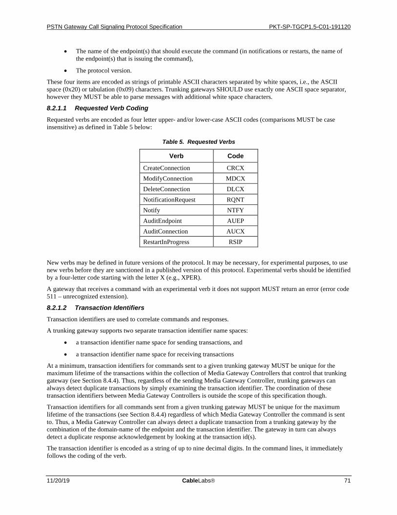
PSTN Gateway Call Signaling Protocol Specification PKT-SP-TGCP1.5-C01-191120
11/20/19 CableLabs 71
• The name of the endpoint(s) that should execute the command (in notifications or restarts, the name of the endpoint(s) that is issuing the command),
• The protocol version.
These four items are encoded as strings of printable ASCII characters separated by white spaces, i.e., the ASCII space (0x20) or tabulation (0x09) characters. Trunking gateways SHOULD use exactly one ASCII space separator, however they MUST be able to parse messages with additional white space characters.
8.2.1.1 Requested Verb Coding
Requested verbs are encoded as four letter upper- and/or lower-case ASCII codes (comparisons MUST be case insensitive) as defined in Table 5 below:
Table 5. Requested Verbs
Verb Code
CreateConnection CRCX ModifyConnection MDCX DeleteConnection DLCX NotificationRequest RQNT Notify NTFY AuditEndpoint AUEP AuditConnection AUCX RestartInProgress RSIP
New verbs may be defined in future versions of the protocol. It may be necessary, for experimental purposes, to use new verbs before they are sanctioned in a published version of this protocol. Experimental verbs should be identified by a four-letter code starting with the letter X (e.g., XPER).
A gateway that receives a command with an experimental verb it does not support MUST return an error (error code 511 – unrecognized extension).
8.2.1.2 Transaction Identifiers
Transaction identifiers are used to correlate commands and responses.
A trunking gateway supports two separate transaction identifier name spaces:
• a transaction identifier name space for sending transactions, and
• a transaction identifier name space for receiving transactions
At a minimum, transaction identifiers for commands sent to a given trunking gateway MUST be unique for the maximum lifetime of the transactions within the collection of Media Gateway Controllers that control that trunking gateway (see Section 8.4.4). Thus, regardless of the sending Media Gateway Controller, trunking gateways can always detect duplicate transactions by simply examining the transaction identifier. The coordination of these transaction identifiers between Media Gateway Controllers is outside the scope of this specification though.
Transaction identifiers for all commands sent from a given trunking gateway MUST be unique for the maximum lifetime of the transactions (see Section 8.4.4) regardless of which Media Gateway Controller the command is sent to. Thus, a Media Gateway Controller can always detect a duplicate transaction from a trunking gateway by the combination of the domain-name of the endpoint and the transaction identifier. The gateway in turn can always detect a duplicate response acknowledgement by looking at the transaction id(s).
The transaction identifier is encoded as a string of up to nine decimal digits. In the command lines, it immediately follows the coding of the verb.
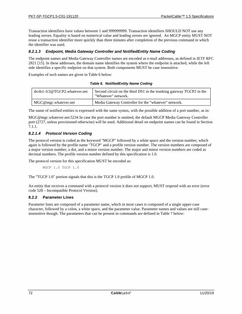
PKT-SP-TGCP1.5-C01-191120 PacketCable™ 1.5 Specifications
72 CableLabs 11/20/19
Transaction identifiers have values between 1 and 999999999. Transaction identifiers SHOULD NOT use any leading zeroes. Equality is based on numerical value and leading zeroes are ignored. An MGCP entity MUST NOT reuse a transaction identifier more quickly than three minutes after completion of the previous command in which the identifier was used.
8.2.1.3 Endpoint, Media Gateway Controller and NotifiedEntity Name Coding
The endpoint names and Media Gateway Controller names are encoded as e-mail addresses, as defined in IETF RFC 2821 [15]. In these addresses, the domain name identifies the system where the endpoint is attached, while the left side identifies a specific endpoint on that system. Both components MUST be case insensitive.
Examples of such names are given in Table 6 below:
Table 6. NotifiedEntity Name Coding
ds/ds1-3/[email protected] Second circuit on the third DS1 in the trunking gateway TGCP2 in the "Whatever" network.
[email protected] Media Gateway Controller for the "whatever" network.
The name of notified entities is expressed with the same syntax, with the possible addition of a port number, as in:
[email protected]:5234 In case the port number is omitted, the default MGCP Media Gateway Controller port (2727, unless provisioned otherwise) will be used. Additional detail on endpoint names can be found in Section 7.1.1.
8.2.1.4 Protocol Version Coding
The protocol version is coded as the keyword "MGCP" followed by a white space and the version number, which again is followed by the profile name "TGCP" and a profile version number. The version numbers are composed of a major version number, a dot, and a minor version number. The major and minor version numbers are coded as decimal numbers. The profile version number defined by this specification is 1.0.
The protocol version for this specification MUST be encoded as: MGCP 1.0 TGCP 1.0
The "TGCP 1.0" portion signals that this is the TGCP 1.0 profile of MGCP 1.0. An entity that receives a command with a protocol version it does not support, MUST respond with an error (error code 528 – Incompatible Protocol Version).
8.2.2 Parameter Lines Parameter lines are composed of a parameter name, which in most cases is composed of a single upper-case character, followed by a colon, a white space, and the parameter value. Parameter names and values are still case-insensitive though. The parameters that can be present in commands are defined in Table 7 below:
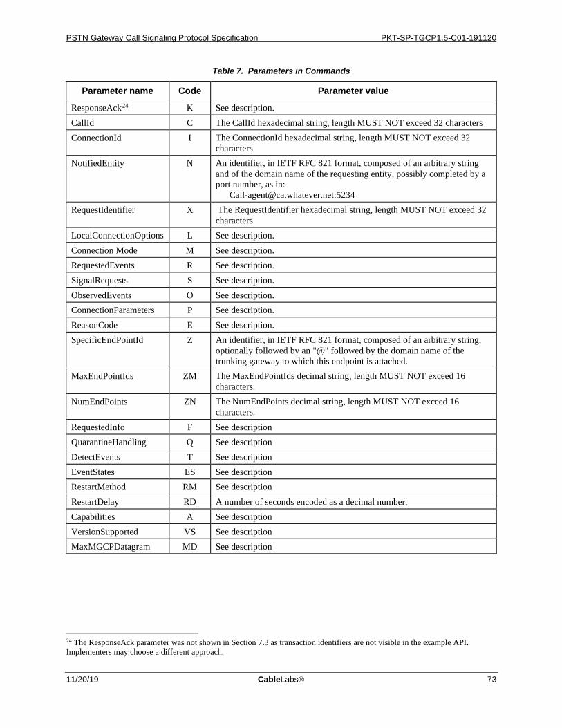
PSTN Gateway Call Signaling Protocol Specification PKT-SP-TGCP1.5-C01-191120
11/20/19 CableLabs 73
Table 7. Parameters in Commands
Parameter name Code Parameter value
ResponseAck24 K See description. CallId C The CallId hexadecimal string, length MUST NOT exceed 32 characters ConnectionId I The ConnectionId hexadecimal string, length MUST NOT exceed 32
characters NotifiedEntity N An identifier, in IETF RFC 821 format, composed of an arbitrary string
and of the domain name of the requesting entity, possibly completed by a port number, as in: [email protected]:5234
RequestIdentifier X The RequestIdentifier hexadecimal string, length MUST NOT exceed 32 characters
LocalConnectionOptions L See description. Connection Mode M See description. RequestedEvents R See description. SignalRequests S See description. ObservedEvents O See description. ConnectionParameters P See description. ReasonCode E See description. SpecificEndPointId Z An identifier, in IETF RFC 821 format, composed of an arbitrary string,
optionally followed by an "@" followed by the domain name of the trunking gateway to which this endpoint is attached.
MaxEndPointIds ZM The MaxEndPointIds decimal string, length MUST NOT exceed 16 characters.
NumEndPoints ZN The NumEndPoints decimal string, length MUST NOT exceed 16 characters.
RequestedInfo F See description QuarantineHandling Q See description DetectEvents T See description EventStates ES See description RestartMethod RM See description RestartDelay RD A number of seconds encoded as a decimal number. Capabilities A See description VersionSupported VS See description MaxMGCPDatagram MD See description
24 The ResponseAck parameter was not shown in Section 7.3 as transaction identifiers are not visible in the example API. Implementers may choose a different approach.
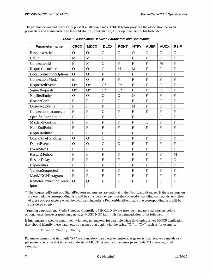
PKT-SP-TGCP1.5-C01-191120 PacketCable™ 1.5 Specifications
74 CableLabs 11/20/19
The parameters are not necessarily present in all commands. Table 8 below provides the association between parameters and commands. The letter M stands for mandatory, O for optional, and F for forbidden:
Table 8. Association Between Parameters and Commands
Parameter name CRCX MDCX DLCX RQNT NTFY AUEP AUCX RSIP
ResponseAck24 O O O O O O O O CallId M M O F F F F F ConnectionId F M O F F F M F RequestIdentifier O O O M M F F F LocalConnectionOptions O O F F F F F F Connection Mode M O F F F F F F RequestedEvents O* O* O* O* F F F F SignalRequests O* O* O* O* F F F F NotifiedEntity O O O O O F F F ReasonCode F F O F F F F F ObservedEvents F F F F M F F F Connection parameters F F O F F F F F Specific Endpoint Id F F F F F O F F MaxEndPointIds F F F F F O F F NumEndPoints F F F F F F F F RequestedInfo F F F F F O O F QuarantineHandling O O O O F F F F DetectEvents O O O O F F F F EventStates F F F F F F F F RestartMethod F F F F F F F M RestartDelay F F F F F F F O Capabilities F F F F F F F F VersionSupported F F F F F F F F MaxMGCPDatagram F F F F F F F F RemoteConnectionDescriptor
O O F F F F F F
* The RequestedEvents and SignalRequests parameters are optional in the NotificationRequest. If these parameters are omitted, the corresponding lists will be considered empty. For the connection handling commands, omission of these two parameters when the command includes a RequestIdentifier means the corresponding lists will be considered empty.
Trunking gateways and Media Gateway Controllers SHOULD always provide mandatory parameters before optional ones, however trunking gateways MUST NOT fail if this recommendation is not followed.
If implementers need to experiment with new parameters, for example when developing a new MGCP application, they should identify these parameters by names that begin with the string "X-" or "X+", such as for example: X-FlowerOfTheDay: Daisy
Parameter names that start with "X+" are mandatory parameter extensions. A gateway that receives a mandatory parameter extension that it cannot understand MUST respond with an error (error code 511 - unrecognized extension).
PSTN Gateway Call Signaling Protocol Specification PKT-SP-TGCP1.5-C01-191120
11/20/19 CableLabs 75
Parameter names that start with "X-" are non-critical parameter extensions. A gateway that receives a non-critical parameter extension that it cannot understand can safely ignore that parameter.
It should be noted that experimental verbs are of the form XABC, whereas experimental parameters are of the form X-ABC.
If a parameter line is received with a forbidden parameter, or any other formatting error, the receiving entity should respond with the most specific error code for the error in question. The least specific error code is 510 – protocol error. Commentary text can always be provided.
8.2.2.1 Response Acknowledgement
The response acknowledgement parameter24 is used to support the three-way handshake described in Section 8.7. It contains a comma separated list of "confirmed transaction-id ranges".
Each "confirmed transaction-id range" is composed of either one decimal number, when the range includes exactly one transaction, or two decimal numbers separated by a single hyphen, describing the lower and higher transaction identifiers included in the range.
An example of a response acknowledgement is: K: 6234-6255, 6257, 19030-19044
8.2.2.2 RequestIdentifier
The request identifier correlates a Notify command with the NotificationRequest (includes notification request embedded in connection handling primitives) that triggered it. A RequestIdentifier is a hexadecimal string; length MUST NOT exceed 32 characters. RequestIdentifiers are compared as strings rather than numerical values. The string "0" is reserved for reporting of persistent events in the case where no NotificationRequest has been received yet (see Section 7.3.2).
8.2.2.3 Local Connection Options
The local connection options describe the operational parameters that the Media Gateway Controllers instructs the gateway to use for a connection. These parameters are:
• The packetization period in milliseconds, encoded as the keyword "p" followed by a colon and a decimal number.
• The multiple packetization period in milliseconds for each codec in the encoding method LCO, encoded as the keyword "mp" followed by a colon and a list of decimal numbers or hyphens, with one entry for each entry in the Encoding Method field. Each packetization period value is separated from its successor by a single semicolon. The first entry in the list MUST be a decimal number. Subsequent entries in the list MUST be either a decimal number or a hyphen.
• The literal name of the compression algorithm as specified in Table 4 in [11], encoded as the keyword "a" followed by a colon and a character string. If the Media Gateway Controller (MGC) specifies a list of values, these values will be separated by a semicolon. For RTP, audio codecs MUST be specified by using encoding names defined in the RTP AV Profile RFC [3], encoding names registered with the IANA, or literal names referenced or defined in the Table 4 of Packet Cable Audio/Video Codecs Specification [11]. Non-audio media registered as a MIME type MUST use the "<MIME type>/<MIME subtype>" form, as in "image/t38". It is RECOMMENDED that other well-known variants of the literal codec names be supported as well.
• The echo-cancellation parameter, encoded as the keyword "e" followed by a colon and the value "on" or "off".
• The type of service parameter, encoded as the keyword "t" followed by a colon and the value encoded as two hexadecimal digits.
• The silence suppression parameter, encoded as the keyword "s" followed by a colon and the value "on" or "off".
The LocalConnectionOptions parameters used for Security are encoded as follows:
PKT-SP-TGCP1.5-C01-191120 PacketCable™ 1.5 Specifications
76 CableLabs 11/20/19
• The RTP ciphersuite is encoded as the keyword "sc-rtp" followed by a colon and an RTP ciphersuite string as defined below. A list of values may be specified in which case the values MUST be separated by a single semicolon.
• The RTCP ciphersuite is encoded as the keyword "sc-rtcp" followed by a colon and an RTCP ciphersuite string as defined below. A list of values may be specified in which case the values MUST be separated by a single semicolon.
The RTP and RTCP ciphersuite strings follow the grammar:
ciphersuite = [AuthenticationAlgorithm] "/" [EncryptionAlgorithm]
AuthenticationAlgorithm = 1*( ALPHA / DIGIT / "-" / "_" )
EncryptionAlgorithm = 1*( ALPHA / DIGIT | "-" / "_" )
where ALPHA, and DIGIT are defined in [17]. Whitespaces MUST NOT be sent within a ciphersuite, or between adjacent ciphersuites when multiple ciphersuites are provided. The following example illustrates the formatting of a ciphersuite and a ciphersuite list: sc-rtp:62/51;64/51;60/50
The actual list of PacketCable supported ciphersuites is provided in the PacketCable Security Specification [12].
When several parameters are present, the values are separated by a comma. It MUST be considered an error to include a parameter without a value (error code 524 –LocalConnectionOptions inconsistency).
Examples of local connection options are: L: p:10, a:PCMU
L: p:10, a:PCMU, e:off, t:20, s:on
L: p:30, a:G729, e:on, t:A0, s:off
The type of service hex value "20" implies an IP precedence of 1, and a type of service hex value of "A0" implies an IP precedence of 5.
This set of attributes may be extended by extension attributes. Extension attributes are composed of an attribute name, followed by a colon, and a semicolon separated list of attribute values. The attribute name MUST start with the two characters "x+", for a mandatory extension, or "x-", for a non-mandatory extension. If a gateway receives a mandatory extension attribute that it does not recognize, it MUST reject the command with an error (error code 525 - Unknown extension in LocalConnectionOptions).
8.2.2.4 Capabilities
Capabilities inform the Media Gateway Controller about its capabilities when audited. The encoding of capabilities is based on the Local Connection Options encoding for the parameters that are common to both. In addition, capabilities can also contain a list of supported packages, and a list of supported modes.
The parameters used are:
• The packetization period in milliseconds, encoded as the keyword "p" followed by a colon and a decimal number. A range may be specified as two decimal numbers separated by a hyphen.
• The literal name of the compression algorithm, encoded as the keyword "a" followed by a colon and a character string. The literal names defined in Table 4 of the PacketCable Audio/Video Codecs Specification [11] MUST be used. A list of values may be specified in which case the values will be separated by a semicolon.
• The bandwidth in kilobits per second (1000 bits per second), encoded as the keyword "b" followed by a colon and a decimal number. A range may be specified as two decimal numbers separated by a hyphen.
• The echo-cancellation parameter, encoded as the keyword "e" followed by a colon and the value "on" if echo cancellation is supported, "off" otherwise.
PSTN Gateway Call Signaling Protocol Specification PKT-SP-TGCP1.5-C01-191120
11/20/19 CableLabs 77
• The type of service parameter, encoded as the keyword "t" followed by a colon and the value "0" if type of service is not supported, all other values indicated support for type of service.
• The silence suppression parameter, encoded as the keyword "s" followed by a colon and the value "on" if silence suppression is supported, "off" otherwise.25
• The event packages supported by this endpoint encoded as the keyword "v" followed by a colon and then a semicolon-separated list of package names supported. The first value specified will be the default package for the endpoint.
• The connection modes supported by this endpoint encoded as the keyword "m" followed by a colon and a semicolon-separated list of connection modes supported as defined in Section 8.2.2.7.
• The keyword "sc-rtp" followed by a colon and a semi-colon separated list of RTP ciphersuites, using the same encoding as in the LocalConnectionOptions.
• The keyword "sc-rtcp" followed by a colon and a semi-colon separated list of RTCP ciphersuites, using the same encoding as in the LocalConnectionOptions.
When several parameters are present, the values are separated by a comma.
Examples of capabilities are: A: a:PCMU; p:10-30, e:on, s:off, v:IT,
m:sendonly;recvonly;sendrecv;inactive
A: a:G729; p:30-90, e:on, s:on, v:IT, m:sendonly;recvonly;sendrecv;inactive, sc-rtp:64/51;60/51, sc-rtcp:71/81
Note that the codecs and security algorithms are merely examples – separate PacketCable specifications detail the actual codecs and algorithms supported, as well as the encoding used (see [11], and [12]). Note also that each set of capabilities is provided on a single line. The examples above show each set on multiple lines due only to formatting restraints of this document.
8.2.2.5 Connection Parameters
Connection parameters are encoded as a string of type and value pairs, where the type is one of the codes in the table below, and the value a decimal integer. Types are separated from values by an "=" sign. Parameters are separated from each other by a comma.
The connection parameter types are specified in Table 9 below:
25 Silence suppression "on" is equivalent to VAD enable and silence suppression "off" is equivalent to VAD disable.
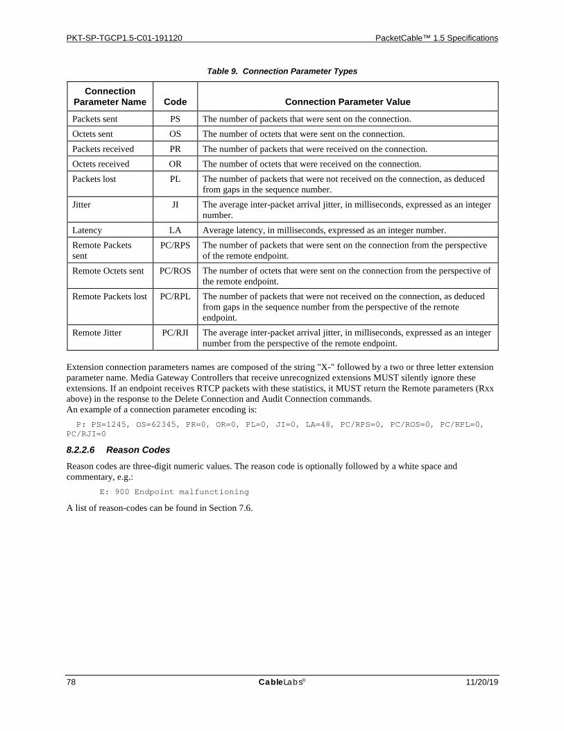
PKT-SP-TGCP1.5-C01-191120 PacketCable™ 1.5 Specifications
78 CableLabs 11/20/19
Table 9. Connection Parameter Types
Connection Parameter Name Code Connection Parameter Value
Packets sent PS The number of packets that were sent on the connection. Octets sent OS The number of octets that were sent on the connection. Packets received PR The number of packets that were received on the connection. Octets received OR The number of octets that were received on the connection. Packets lost PL The number of packets that were not received on the connection, as deduced
from gaps in the sequence number. Jitter JI The average inter-packet arrival jitter, in milliseconds, expressed as an integer
number. Latency LA Average latency, in milliseconds, expressed as an integer number. Remote Packets sent
PC/RPS The number of packets that were sent on the connection from the perspective of the remote endpoint.
Remote Octets sent PC/ROS The number of octets that were sent on the connection from the perspective of the remote endpoint.
Remote Packets lost PC/RPL The number of packets that were not received on the connection, as deduced from gaps in the sequence number from the perspective of the remote endpoint.
Remote Jitter PC/RJI The average inter-packet arrival jitter, in milliseconds, expressed as an integer number from the perspective of the remote endpoint.
Extension connection parameters names are composed of the string "X-" followed by a two or three letter extension parameter name. Media Gateway Controllers that receive unrecognized extensions MUST silently ignore these extensions. If an endpoint receives RTCP packets with these statistics, it MUST return the Remote parameters (Rxx above) in the response to the Delete Connection and Audit Connection commands. An example of a connection parameter encoding is: P: PS=1245, OS=62345, PR=0, OR=0, PL=0, JI=0, LA=48, PC/RPS=0, PC/ROS=0, PC/RPL=0, PC/RJI=0
8.2.2.6 Reason Codes
Reason codes are three-digit numeric values. The reason code is optionally followed by a white space and commentary, e.g.: E: 900 Endpoint malfunctioning
A list of reason-codes can be found in Section 7.6.
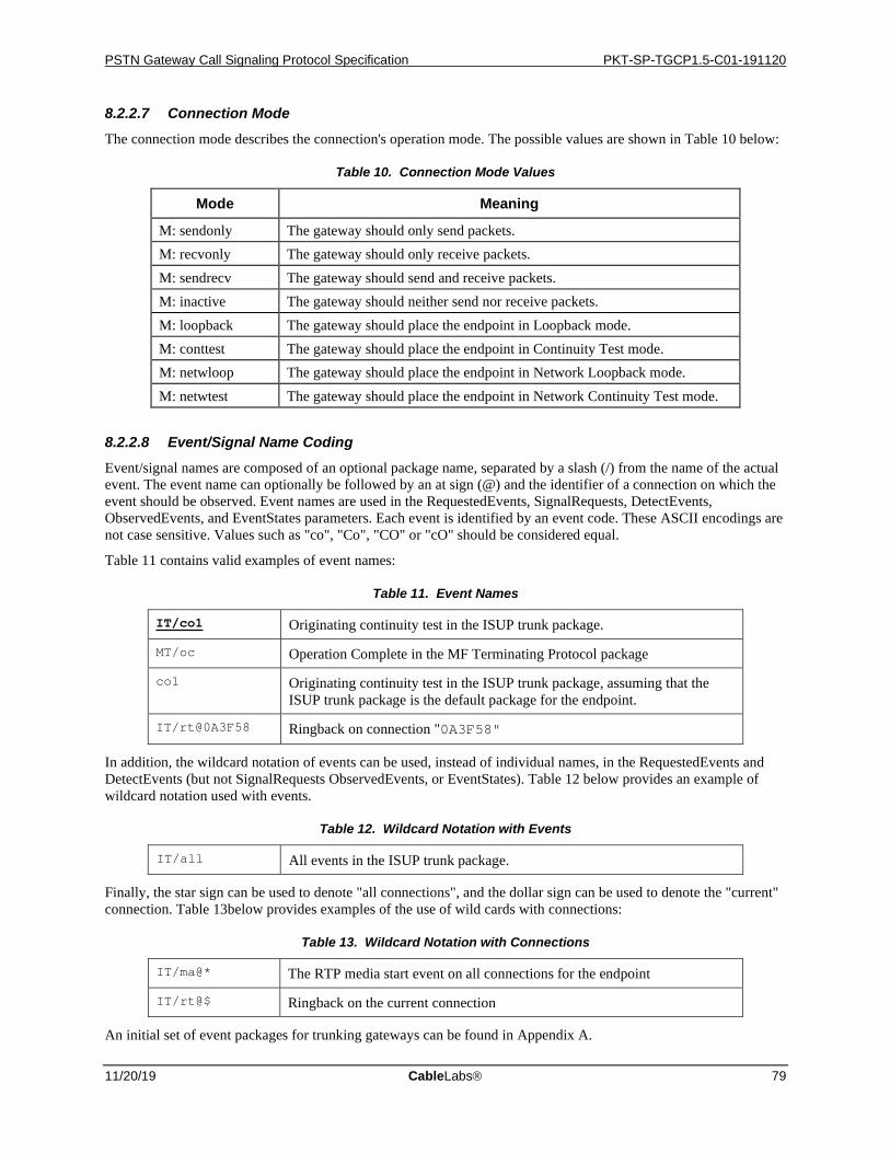
PSTN Gateway Call Signaling Protocol Specification PKT-SP-TGCP1.5-C01-191120
11/20/19 CableLabs 79
8.2.2.7 Connection Mode
The connection mode describes the connection's operation mode. The possible values are shown in Table 10 below:
Table 10. Connection Mode Values
Mode Meaning
M: sendonly The gateway should only send packets. M: recvonly The gateway should only receive packets. M: sendrecv The gateway should send and receive packets. M: inactive The gateway should neither send nor receive packets. M: loopback The gateway should place the endpoint in Loopback mode. M: conttest The gateway should place the endpoint in Continuity Test mode. M: netwloop The gateway should place the endpoint in Network Loopback mode. M: netwtest The gateway should place the endpoint in Network Continuity Test mode.
8.2.2.8 Event/Signal Name Coding
Event/signal names are composed of an optional package name, separated by a slash (/) from the name of the actual event. The event name can optionally be followed by an at sign (@) and the identifier of a connection on which the event should be observed. Event names are used in the RequestedEvents, SignalRequests, DetectEvents, ObservedEvents, and EventStates parameters. Each event is identified by an event code. These ASCII encodings are not case sensitive. Values such as "co", "Co", "CO" or "cO" should be considered equal.
Table 11 contains valid examples of event names:
Table 11. Event Names
IT/co1 Originating continuity test in the ISUP trunk package.
MT/oc Operation Complete in the MF Terminating Protocol package
co1 Originating continuity test in the ISUP trunk package, assuming that the ISUP trunk package is the default package for the endpoint.
IT/rt@0A3F58 Ringback on connection "0A3F58"
In addition, the wildcard notation of events can be used, instead of individual names, in the RequestedEvents and DetectEvents (but not SignalRequests ObservedEvents, or EventStates). Table 12 below provides an example of wildcard notation used with events.
Table 12. Wildcard Notation with Events
IT/all All events in the ISUP trunk package.
Finally, the star sign can be used to denote "all connections", and the dollar sign can be used to denote the "current" connection. Table 13below provides examples of the use of wild cards with connections:
Table 13. Wildcard Notation with Connections
IT/ma@* The RTP media start event on all connections for the endpoint
IT/rt@$ Ringback on the current connection
An initial set of event packages for trunking gateways can be found in Appendix A.
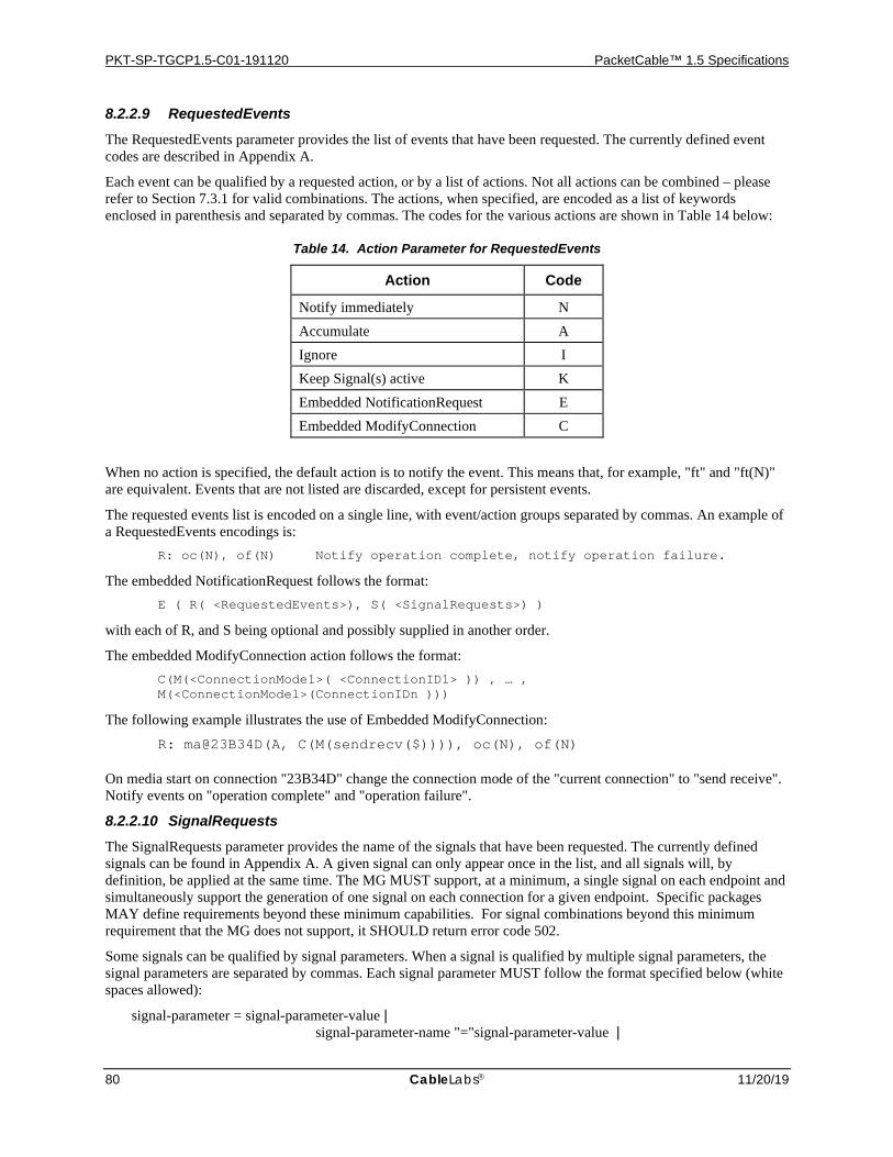
PKT-SP-TGCP1.5-C01-191120 PacketCable™ 1.5 Specifications
80 CableLabs 11/20/19
8.2.2.9 RequestedEvents
The RequestedEvents parameter provides the list of events that have been requested. The currently defined event codes are described in Appendix A.
Each event can be qualified by a requested action, or by a list of actions. Not all actions can be combined – please refer to Section 7.3.1 for valid combinations. The actions, when specified, are encoded as a list of keywords enclosed in parenthesis and separated by commas. The codes for the various actions are shown in Table 14 below:
Table 14. Action Parameter for RequestedEvents
Action Code
Notify immediately N Accumulate A Ignore I Keep Signal(s) active K Embedded NotificationRequest E Embedded ModifyConnection C
When no action is specified, the default action is to notify the event. This means that, for example, "ft" and "ft(N)" are equivalent. Events that are not listed are discarded, except for persistent events.
The requested events list is encoded on a single line, with event/action groups separated by commas. An example of a RequestedEvents encodings is:
R: oc(N), of(N) Notify operation complete, notify operation failure.
The embedded NotificationRequest follows the format: E ( R( <RequestedEvents>), S( <SignalRequests>) )
with each of R, and S being optional and possibly supplied in another order.
The embedded ModifyConnection action follows the format: C(M(<ConnectionMode1>( <ConnectionID1> )) , … ,
M(<ConnectionModel>(ConnectionIDn )))
The following example illustrates the use of Embedded ModifyConnection: R: ma@23B34D(A, C(M(sendrecv($)))), oc(N), of(N)
On media start on connection "23B34D" change the connection mode of the "current connection" to "send receive". Notify events on "operation complete" and "operation failure".
8.2.2.10 SignalRequests
The SignalRequests parameter provides the name of the signals that have been requested. The currently defined signals can be found in Appendix A. A given signal can only appear once in the list, and all signals will, by definition, be applied at the same time. The MG MUST support, at a minimum, a single signal on each endpoint and simultaneously support the generation of one signal on each connection for a given endpoint. Specific packages MAY define requirements beyond these minimum capabilities. For signal combinations beyond this minimum requirement that the MG does not support, it SHOULD return error code 502.
Some signals can be qualified by signal parameters. When a signal is qualified by multiple signal parameters, the signal parameters are separated by commas. Each signal parameter MUST follow the format specified below (white spaces allowed):
signal-parameter = signal-parameter-value | signal-parameter-name "="signal-parameter-value |
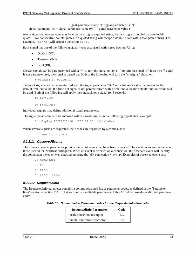
PSTN Gateway Call Signaling Protocol Specification PKT-SP-TGCP1.5-C01-191120
11/20/19 CableLabs 81
signal-parameter-name "(" signal-parameter-list ")" signal-parameter-list = signal-parameter-value 0*( "," signal-parameter-value )
where signal-parameter-value may be either a string or a quoted string, i.e., a string surrounded by two double quotes. Two consecutive double-quotes in a quoted string will escape a double-quote within that quoted string. For example, "ab""c" will produce the string ab"c.
Each signal has one of the following signal-types associated with it (see Section 7.3.1):
• On/Off (OO),
• Time-out (TO),
• Brief (BR).
On/Off signals can be parameterized with a "+" to turn the signal on, or a "-" to turn the signal off. If an on/off signal is not parameterized, the signal is turned on. Both of the following will turn the "mysignal" signal on: mysignal(+), mysignal
Time-out signals can be parameterized with the signal parameter "TO" and a time-out value that overrides the default time-out value. If a time-out signal is not parameterized with a time-out value the default time-out value will be used. Both of the following will apply the ringback tone signal for 6 seconds: rt(to=6000)
rt(to(6000))
Individual signals may define additional signal parameters.
The signal parameters will be enclosed within parenthesis, as in the following hypothetical example: S: display(10/14/17/26, "555 1212", CableLabs)
When several signals are requested, their codes are separated by a comma, as in: S: signal1, signal2
8.2.2.11 ObservedEvents
The observed events parameters provide the list of events that have been observed. The event codes are the same as those used in the NotificationRequest. When an event is detected on a connection, the observed event will identify the connection the event was detected on using the "@<connection>" syntax. Examples of observed events are: O: ma@A43B81
O: ft
O: IT/ft
O: IT/ft, IT/mt
8.2.2.12 RequestedInfo
The RequestedInfo parameter contains a comma separated list of parameter codes, as defined in the "Parameter lines" section – Section 7.3.8 That section lists auditable parameters. Table 15 below provides additional parameter codes:
Table 15. Non-auditable Parameter codes for the RequestedInfo Parameter
RequestedInfo Parameter Code LocalConnectionDescriptor LC RemoteConnectionDescriptor RC

PKT-SP-TGCP1.5-C01-191120 PacketCable™ 1.5 Specifications
82 CableLabs 11/20/19
For example, if one wants to audit the value of the NotifiedEntity, RequestIdentifier, RequestedEvents, SignalRequests, DetectEvents, EventStates, LocalConnectionDescriptor, and RemoteConnectionDescriptor parameters, the value of the RequestedInfo parameter will be:
F: N, X, R, S, T, ES, LC, RC
The capabilities request, for the AuditEndPoint command, is encoded by the parameter code "A", as in: F: A
8.2.2.13 QuarantineHandling
The quarantine handling parameter contains a list of comma separated keywords:
• The keyword "process" or "discard" to indicate the treatment of quarantined and observed events. If neither process nor discard is present, process is assumed.
• The keyword "step" or "loop" to indicate whether, at most, one notification is expected, or whether multiple notifications are allowed. If neither "step" nor "loop" is present, "step" is assumed. Support for these two keywords is mandatory.
The following values are valid examples: Q: loop Q: process Q: loop,discard
8.2.2.14 DetectEvents
The DetectEvents parameter is encoded as a comma separated list of events, such as for example: T: ft, mt
It should be noted, that no actions can be associated with the events.
8.2.2.15 EventStates
The EventStates parameter is encoded as a comma separated list of events, such as for example: ES: MO/rlc
It should be noted, that no actions can be associated with the events.
8.2.2.16 RestartMethod
The RestartMethod parameter is encoded as one of the keywords "graceful", "cancel-graceful," "forced", "restart", or "disconnected", as for example:
RM: restart
8.2.2.17 VersionSupported
The VersionSupported parameter is encoded as a comma separated list of versions supported, such as for example: VS: MGCP 1.0, MGCP 1.0 TGCP 1.0
8.2.2.18 Call Identifier
The Call Identifier is encoded as a hexadecimal string, at most 32 characters. Call Identifiers are compared as strings rather than numerical values.
8.2.2.19 Connection Identifier
The Connection Identifier is encoded as a hexadecimal string, at most 32 characters. Connection Identifiers are compared as strings rather than numerical values.
PSTN Gateway Call Signaling Protocol Specification PKT-SP-TGCP1.5-C01-191120
11/20/19 CableLabs 83
8.2.2.20 MaxMGCPDatagram
The MaxMGCPDatagram parameter is encoded as a string of up to nine decimal digits - leading zeroes are not permitted. The following example illustrates the use of this parameter:
MD: 8100
8.3 Response Header Formats The response header is composed of a response line optionally followed by headers that encode the response parameters.
The response line starts with the response code, which is a three-digit numeric value. The code is followed by a white space, the transaction identifier, and optional commentary preceded by a white space, e.g.: 200 1201 OK
Table 16 below summarizes the response parameters whose presence is mandatory or optional in a response header, as a function of the command that triggered the response. The reader should still study the individual command definitions though as this table only provides summary information. The letter M stands for mandatory, O for optional and F for forbidden.
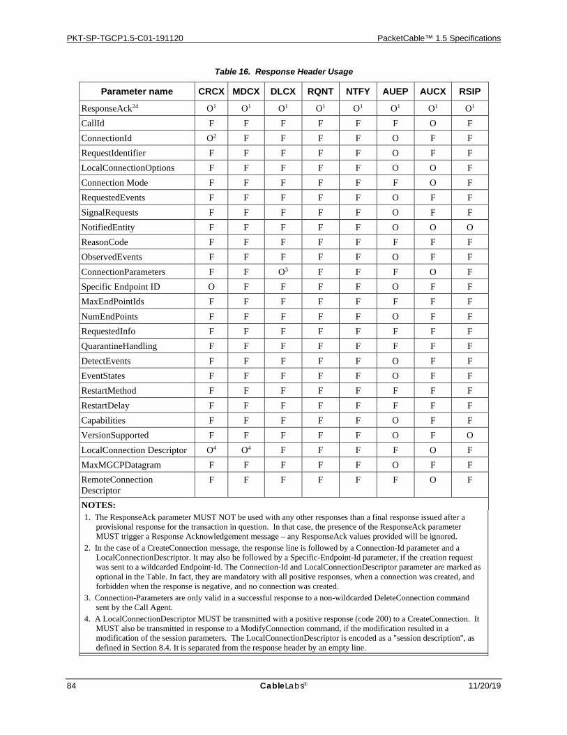
PKT-SP-TGCP1.5-C01-191120 PacketCable™ 1.5 Specifications
84 CableLabs 11/20/19
Table 16. Response Header Usage
Parameter name CRCX MDCX DLCX RQNT NTFY AUEP AUCX RSIP
ResponseAck24 O1 O1 O1 O1 O1 O1 O1 O1 CallId F F F F F F O F ConnectionId O2 F F F F O F F RequestIdentifier F F F F F O F F LocalConnectionOptions F F F F F O O F Connection Mode F F F F F F O F RequestedEvents F F F F F O F F SignalRequests F F F F F O F F NotifiedEntity F F F F F O O O ReasonCode F F F F F F F F ObservedEvents F F F F F O F F ConnectionParameters F F O3 F F F O F Specific Endpoint ID O F F F F O F F MaxEndPointIds F F F F F F F F NumEndPoints F F F F F O F F RequestedInfo F F F F F F F F QuarantineHandling F F F F F F F F DetectEvents F F F F F O F F EventStates F F F F F O F F RestartMethod F F F F F F F F RestartDelay F F F F F F F F Capabilities F F F F F O F F VersionSupported F F F F F O F O LocalConnection Descriptor O4 O4 F F F F O F MaxMGCPDatagram F F F F F O F F RemoteConnection Descriptor
F F F F F F O F
NOTES: 1. The ResponseAck parameter MUST NOT be used with any other responses than a final response issued after a
provisional response for the transaction in question. In that case, the presence of the ResponseAck parameter MUST trigger a Response Acknowledgement message – any ResponseAck values provided will be ignored.
2. In the case of a CreateConnection message, the response line is followed by a Connection-Id parameter and a LocalConnectionDescriptor. It may also be followed by a Specific-Endpoint-Id parameter, if the creation request was sent to a wildcarded Endpoint-Id. The Connection-Id and LocalConnectionDescriptor parameter are marked as optional in the Table. In fact, they are mandatory with all positive responses, when a connection was created, and forbidden when the response is negative, and no connection was created.
3. Connection-Parameters are only valid in a successful response to a non-wildcarded DeleteConnection command sent by the Call Agent.
4. A LocalConnectionDescriptor MUST be transmitted with a positive response (code 200) to a CreateConnection. It MUST also be transmitted in response to a ModifyConnection command, if the modification resulted in a modification of the session parameters. The LocalConnectionDescriptor is encoded as a "session description", as defined in Section 8.4. It is separated from the response header by an empty line.
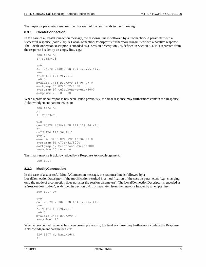
PSTN Gateway Call Signaling Protocol Specification PKT-SP-TGCP1.5-C01-191120
11/20/19 CableLabs 85
The response parameters are described for each of the commands in the following.
8.3.1 CreateConnection In the case of a CreateConnection message, the response line is followed by a Connection-Id parameter with a successful response (code 200). A LocalConnectionDescriptor is furthermore transmitted with a positive response. The LocalConnectionDescriptor is encoded as a "session description", as defined in Section 8.4. It is separated from the response header by an empty line, e.g.:
200 1204 OK I: FDE234C8 v=0 o=- 25678 753849 IN IP4 128.96.41.1 s=- c=IN IP4 128.96.41.1 t=0 0 m=audio 3456 RTP/AVP 18 96 97 0 a=rtpmap:96 G726-32/8000 a=rtpmap:97 telephone-event/8000 a=mptime:20 10 – 10
When a provisional response has been issued previously, the final response may furthermore contain the Response Acknowledgement parameter, as in:
200 1204 OK K: I: FDE234C8 v=0 o=- 25678 753849 IN IP4 128.96.41.1 s=- c=IN IP4 128.96.41.1 t=0 0 m=audio 3456 RTP/AVP 18 96 97 0 a=rtpmap:96 G726-32/8000 a=rtpmap:97 telephone-event/8000 a=mptime:20 10 – 10
The final response is acknowledged by a Response Acknowledgement: 000 1204
8.3.2 ModifyConnection In the case of a successful ModifyConnection message, the response line is followed by a LocalConnectionDescriptor, if the modification resulted in a modification of the session parameters (e.g., changing only the mode of a connection does not alter the session parameters). The LocalConnectionDescriptor is encoded as a "session description", as defined in Section 8.4. It is separated from the response header by an empty line.
200 1207 OK v=0 o=- 25678 753849 IN IP4 128.96.41.1 s=- c=IN IP4 128.96.41.1 t=0 0 m=audio 3456 RTP/AVP 0 a=mptime: 20
When a provisional response has been issued previously, the final response may furthermore contain the Response Acknowledgement parameter as in:
526 1207 No bandwidth K:
PKT-SP-TGCP1.5-C01-191120 PacketCable™ 1.5 Specifications
86 CableLabs 11/20/19
The final response is acknowledged by a Response Acknowledgement: 000 1207 OK
8.3.3 DeleteConnection Depending on the variant of the DeleteConnection message, the response line may be followed by a Connection Parameters parameter line, as defined in Section 8.2.2.5.
250 1210 OK P: PS=1245, OS=62345, PR=780, OR=45123, PL=10, JI=27, LA=48
8.3.4 NotificationRequest A NotificationRequest response does not include any additional response parameters.
8.3.5 Notify A Notify response does not include any additional response parameters.
8.3.6 AuditEndpoint In the case of an AuditEndPoint the response line may be followed by information for each of the parameters requested—each parameter will appear on a separate line. Parameters for which no value currently exists will still be provided. Each local endpoint name "expanded" by a wildcard character will appear on a separate line using the "SpecificEndPointId" parameter code, e.g.:
200 1200 OK
Z: ds/ds1-1/[email protected]
Z: ds/ds1-1/[email protected]
ZN: 24
An example of a response to an AuditEndPoint message containing a non-wildcarded endpoint name is shown below. Note that the SpecificEndPointId is not provided in this case. Note also that each set of capabilities is provided on a single line. The example below shows each set on multiple lines due only to formatting restraints of this document. 200 1200 OK
A: a:PCMU, p:10, e:on, s:off, t:1, v:IT, m:sendonly;recvonly;sendrecv;inactive A: a:G728, p:20, e:on, s:off, t:1, v:IT, m:sendonly;recvonly;sendrecv;inactive A: a:G729; p:30-90, e:on, s:on, t:1, v:L, m:sendonly;recvonly;sendrecv;inactive;confrnce
8.3.7 AuditConnection In the case of an AuditConnection, the response may be followed by information for each of the parameters requested. Parameters for which no value currently exists will still be provided. Connection descriptors will always appear last and each will be preceded by an empty line, as for example:
200 1203 OK C: A3C47F21456789F0 N: [128.96.41.12] L: mp:20;10, a:PCMU;G728 M: sendrecv P: PS=622, OS=31172, PR=390, OR=22561, PL=5, JI=29, LA=50 v=0 o=- 4723891 7428910 IN IP4 128.96.63.25 s=- c=IN IP4 128.96.63.25 t=0 0 m=audio 1296 RTP/AVP 96 a=rtpmap:96 G728/8000
PSTN Gateway Call Signaling Protocol Specification PKT-SP-TGCP1.5-C01-191120
11/20/19 CableLabs 87
a=mptime: 10
If both a local and a remote connection descriptor are provided, the local connection descriptor will be the first of the two. If a connection descriptor is requested, but it does not exist for the connection audited, that connection descriptor will appear with the SDP protocol version field only.
8.3.8 RestartInProgress The response to a RestartInProgress may include the name of another Media Gateway Controller to contact, for instance when the Media Gateway Controller redirects the endpoint to another Media Gateway Controller as in:
521 1204 Redirect N: [email protected]
8.4 Session Description Encoding The session description is encoded in conformance with the session description protocol (SDP), however, trunking gateways may make certain simplifying assumptions about the session description as specified in the following. It should be noted, that session descriptions are case sensitive per [4].
SDP usage depends on the type of session, as specified in the "media" parameter.
• If the media is set to "audio", the session description is for an audio service.
• If the media is set to "image", the session description is for an image service such as FAX.
8.4.1 Use of SDP In a trunking gateway, we only have to describe sessions that use exactly one MIME media type at a given point in time; either "audio" (for voice or voice-band data) or "image" (for T.38 fax calls). The parameters of SDP that are relevant for both the "audio" and "image" based media types are specified in Section 8.4.2. Parameters specific to "audio" are specified in the Section 8.4.3. Parameters specific to "image" when used for T.38 are specific in Section 8.4.4. Trunking gateway MUST support session descriptions that conform to these rules and in the following order:
1. The SDP profile presented below
2. IETF RFC 2327 (SDP: Session Description Protocol) [4]
The MGC should be careful if it is necessary to alter the SDP received from an endpoint. SDP provides a means of communicating the capabilities of an endpoint to another endpoint. If the MGC chooses to modify the SDP, it MUST NOT alter the SDP such that it violates the rules defined in this section.
The SDP profile provided describes the use of the session description protocol in TGCP. The general description and explanation of the individual parameters as well as most of the parameters being used for audio only can be found in [4]. Parameters specific to T.38 for image can be found in [26]. Below we detail what values TGCP endpoints need to provide for these fields (send) and what TGCP endpoints should do with values supplied or not supplied for these fields (receive). It should be noted, that the SDP profile used here does not comply with the offer/answer model defined in RFC3264 [42]. Thus, if a MGC needs to interact with another entity that uses the offer/answer model, the MGC may need to edit the SDP it receives from the endpoint.
8.4.2 SDP Parameters Common to both Audio (m=audio media line) and Image (m=image media line) Service Use
8.4.2.1 Protocol Version (v=)
v= <version> v= 0
Send: MUST be provided in accordance with [4] (i.e., v=0), Receive: MUST be provided in accordance with [4].

PKT-SP-TGCP1.5-C01-191120 PacketCable™ 1.5 Specifications
88 CableLabs 11/20/19
8.4.2.2 Origin (o=)
The origin field consists (o=) of 6 sub-fields in [4]:
o= <username> <session-ID> <version> <network-type> <address-type> <address> o= - 2987933615 2987933615 IN IP4 126.16.64.4
Username Send: Hyphen MUST be used as username when privacy is requested. Hyphen SHOULD be used
otherwise. Since TGCP endpoints do not know when privacy is requested, they SHOULD always use a hyphen.
Receive: This field SHOULD be ignored.
Session-ID Send: MUST be in accordance with [4] for interoperability with non-PacketCable clients. Receive: This field SHOULD be ignored.
Version Send: In accordance with [4]. Receive: This field SHOULD be ignored.
Network Type Send: Type 'IN' MUST be used. Receive: This field SHOULD be ignored.
Address Type Send: Type "IP4" MUST be used Receive: This field SHOULD be ignored.
Address: Send: MUST be in accordance with [4] for interoperability with non-PacketCable clients. Receive: This field MUST be ignored.
8.4.2.3 Session Name (s=)
s= <session-name> s= -
Send: Hyphen MUST be used as Session name. Receive: This field MUST be ignored.
8.4.2.4 Session and Media Information (i=)
i= <session-description> Send: For TGCP, the field MUST NOT be used. Receive: This field MUST be ignored.
8.4.2.5 URI (u=)
u= <URI> Send: For TGCP, the field MUST NOT be used. Receive: This field MUST be ignored.
8.4.2.6 E-Mail Address and Phone Number (e=, p=)
e= <e-mail-address> p= <phone-number>
Send: For TGCP, the field MUST NOT be used. Receive: This field MUST be ignored.
8.4.2.7 Connection Data (c=)
The connection data consists of 3 sub-fields:
c= <network-type> <address-type> <connection-address> c= IN IP4 10.10.111.11

PSTN Gateway Call Signaling Protocol Specification PKT-SP-TGCP1.5-C01-191120
11/20/19 CableLabs 89
Network Type: Send: Type 'IN' MUST be used. Receive: Type "IN" MUST be present.
Address Type: Send: Type "IP4" MUST be used Receive: Type "IP4" MUST be present.
Connection Address: Send: This field MUST be filled with a unicast IP address at which the application will receive the media
stream. Thus, a TTL value MUST NOT be present and a "number of addresses" value MUST NOT be present. The field MUST NOT be filled with a fully-qualified domain name instead of an IP address. A non-zero address specifies both the send and receive address for the media stream(s) it covers.
Receive: A unicast IP address or a fully qualified domain name MUST be present. A non-zero address specifies both the send and receive address for the media stream(s) it covers.
8.4.2.8 Bandwidth (b=)
b= <modifier> : <bandwidth-value> b= AS : 64
Send: Bandwidth information is optional in SDP, but it SHOULD always be included. If this field is not used, the Gate Controller might not authorize the appropriate bandwidth. When an rtpmap or a non well-known codec is used, the bandwidth information MUST be used. (A non well-known codec is a codec not defined in the PacketCable codec specification[11].)
Receive: Bandwidth information SHOULD be included. If a bandwidth line is not included, the receiver MUST assume reasonable default bandwidth values for well-known encoding methods.
Modifier: Send: Type 'AS' MUST be used. Receive: Type "AS" MUST be present.
Bandwidth Value: Send: The field MUST be filled with the Maximum Bandwidth requirement of the Media stream in
kilobits per second. Refer to the PacketCable Codec specification [11], section 7.5 for the details of calculating the bandwidth value. When RFC 2198 Redundancy is included in SDP, the bandwidth value included MUST include the maximum bandwidth required for use of redundancy with the specified depth.
Receive: The maximum bandwidth requirement of the media stream in kilobits per second MUST be present.
8.4.2.9 Time, Repeat Times and Time Zones (t=, r=, z=)
t= <start-time> <stop-time> t= 36124033 0 r= <repeat-interval> <active-duration> <list-of-offsets-from-start-time> z= <adjustment-time> <offset>
Send: Time MUST be present; start time MAY be zero, but SHOULD be the current time, and stop time SHOULD be zero. Repeat Times, and Time Zones SHOULD NOT be used, if they are used it should be in accordance with [4].
Receive: If any of these fields are present, they SHOULD be ignored.
8.4.2.10 Attributes (a=)
a= <attribute> : <value> a= mptime: <alternative 1> <alternative 2> …a = X-pc-bridge: <number-ports> a= <attribute> a= recvonly a= sendrecv a= sendonly
PKT-SP-TGCP1.5-C01-191120 PacketCable™ 1.5 Specifications
90 CableLabs 11/20/19
a= ptime a=pmft: <modem-fax-transport>t
Send: One or more of the "a" attribute lines specified below MAY be included. Receive: One or more of the "a" attribute lines specified below MAY be included and MUST be acted upon
accordingly.
Note that SDP [4] requires unknown attributes to be ignored.
mptime: This attribute defines a list of packetization period values the endpoint is capable of using (sending and receiving) for this connection.
Send: This attribute MUST be present. There MUST be precisely one entry in the list for each <format> entry provided in the "m=" line. Entry number j in this list defines the packetization period for entry number j in the "m=" line. The first entry in the list MUST be a decimal number whereas subsequent entries in the list MUST be either a decimal number or a hyphen. For those media formats where a single packetization rate does not apply (e.g., non-voice codecs such as telephone event or comfort noise), a hyphen ("-") MUST be encoded at the corresponding location in the list of packetization periods.
Receive: Conveys the list of packetization periods that the remote endpoint is capable of using for this connection; one for each media format in the "m=" line. For media formats whose packetization period is specified as a hyphen ("-"), the endpoint MUST use one of the packetization periods that was actually specified in the list If the "mptime" attribute is absent, then the value of the "ptime" attribute, if present, MUST be taken as indicating the packetization period for all codecs present in the "m=" line. If neither the "mptime" nor the "ptime" attribute is present, then the MG must assume the default value for well-known codecs (as defined in RFC 3551 [3]).
X-pc-bridge:
Send: TGCP endpoints MUST NOT use this attribute. Receive: TGCP endpoints MUST ignore this attribute if received.
recvonly: Send: This field should not be supplied by a TGCP endpoint. Receive: The field MUST be ignored.
sendrecv: Send: This field should not be supplied by a TGCP endpoint. Receive: . The field MUST be ignored.
sendonly: Send: This field should not be supplied by a TGCP endpoint. Receive: The field MUST be ignored
ptime: Send: The ptime SHOULD be sent if it was received in a RemoteConnectionDescriptor or if the MGC
used the packetization period ('p:') LocalConnectionOption. Receive: The field MUST be ignored if the SDP contains the "mptime" attribute (as required in
PacketCable compliant devices). If the "mptime" attribute is not present, then this field is used to define the packetization interval for all codecs present in the SDP description. If neither "mptime" nor "ptime" is present, the MG MUST assume reasonable default values for well-known codecs as defined in [11].
PSTN Gateway Call Signaling Protocol Specification PKT-SP-TGCP1.5-C01-191120
11/20/19 CableLabs 91
pmft:
This is a session level attribute defined in ITU V.152 [30].
Send: The MG MUST NOT send the a=pmft line unless both the FXR and VBD packages are specified in the LCO by the MGC. An a=pmft: T38 line MUST be sent if V.152 is present in the Local Connection Descriptor and the LCO has one of the following two fxr/fx formats fxr/fx:t38-loose fxr/fx:t38;gw If sent, the a=pmft line MUST be placed at the session level. If any other fxr/fx format allowed in Section 7.7.4 is used, the endpoint MUST NOT send an a=pmft line. An a=pmft line with modem-fax-transport other than T38 MUST NOT be sent.
Receive: The field MUST be ignored if present in the RemoteConnectionDescriptor.
8.4.3 SDP Audio Service Use The following SDP parameters are applied at the media level and are specific to Audio Service Use. Audio Service Use includes VBD mode as defined in V.152 [30]. PacketCable endpoints MUST NOT send any of these parameters within an image media descriptor (see Section 8.4.4). If, however, the endpoint receives an SDP with attribute parameters specific to image only within an audio media descriptor, the parameters SHOULD be ignored. Further, when media capability parameters are to be provided, each media capability descriptor (which includes the capability description line, a=cdsc, along with 0 or more capability attribute lines, e.g., a=cpar) MUST appear after the last media attribute and each media capability descriptor MUST be listed separately.
8.4.3.1 Encryption Keys:
k= <method> k= <method> : <encryption-keys>
Security services for PacketCable are defined by the PacketCable Security specification [12]. The security services specified for RTP and RTCP do not comply with those of [2], [3]and [4]. In the interest of interoperability with non-PacketCable devices, the "k" parameter will therefore not be used to convey security parameters.
Send: MUST NOT be used.
Receive: This field SHOULD be ignored.
8.4.3.2 Attributes (a=)
a= <attribute> : <value> a= rtpmap : <payload type> <encoding name>/<clock rate> [/<encoding parameters>] a= rtpmap : 0 PCMU / 8000 a=fmtp:<format> <format specific parameters> a= X-pc-codecs: <alternative 1> <alternative 2> a= X-pc-secret: <method>:<encryption key>[pad] a = X-pc-csuites-rtp: <alternative 1> <alternative 2> … a = X-pc-csuites-rtcp: <alternative 1> <alternative 2> … a=gpmd:<format> <parameter list>
Send: One or more of the "a" attribute lines specified below MAY be included. Receive: One or more of the "a" attribute lines specified below MAY be included and MUST be acted upon
accordingly. Note that SDP [4] requires unknown attributes to be ignored.
PKT-SP-TGCP1.5-C01-191120 PacketCable™ 1.5 Specifications
92 CableLabs 11/20/19
rtpmap:
Send: When used, the field MUST be used in accordance with [4]. This field MAY be used for well-known as well as well as non well-known codecs. The encoding names used are provided separate PacketCable specifications (see [11] and [12].) On a given connection, the dynamic payload type for a given encoding method MUST be the same in the send and receive direction. Furthermore, on a given connection, once a dynamic payload type has been mapped to a given encoding method, that payload type MUST NOT subsequently be mapped to another encoding method.
Receive: When used, the field MUST be used in accordance with [4]. For a given connection, implementations SHOULD NOT fail if a given encoding method is mapped to different payload types in the send and receive direction, or if a given payload type is remapped.
fmtp: Send: This field MAY be used to provide parameters specific to a particular format. For example, the field
could be used to describe telephone events supported for an RFC 2833 [24] format. When used, the format MUST be one of the formats specified for the media. The parameters specified are provided in a separate specification that details the usage of the format.
Receive: When used, the field MUST be used in accordance with [4].
X-pc-codecs:
Send: The field contains a list of alternative codecs that the endpoint is capable of using for this connection. The list is ordered by decreasing degree of preference, i.e., the most preferred alternative codec is the first one in the list. A codec is encoded similarly to "encoding name" in rtpmap.
Receive: Conveys a list of codecs that the remote endpoint is capable of using for this connection. The codecs MUST NOT be used until signaled through a media (m=) line.
X-pc-secret: Send: The field contains an end-to-end secret and (possibly) the PAD to be used for RTP and RTCP
security. The secret and pad are encoded similarly to the encryption key (k=) parameter of [4] with the following constraints:
• The encryption key MUST NOT contain a ciphersuite, only a passphrase.
• The <method> specifying the encoding of the pass-phrase MUST be either "clear" or "base64" as defined in RFC 2045 [23], except for the maximum line length which is not specified here. The method "clear" MUST NOT be used if the secret contains any characters that are prohibited in SDP.
The requirements for when to transmit PAD are described in [8]. If present, it MUST be separated by at least one whitespace from the secret Pad and secret MUST use the same encode method.
Receive: Conveys the end-to-end secret to be used for RTP and RTCP security. If present, its use is as described in the PacketCable Security Specification [12] and it MUST be separated by at least one white space from the secret. Pad and secret MUST use the same encode method. X-pc-csuites-rtp:
X-pc-csuites-rtcp:
Send: The field contains a list of ciphersuites that the endpoint is capable of using for this connection (respectively RTP and RTCP). The first ciphersuite listed is what the endpoint is currently expecting to use. Any remaining ciphersuites in the list represent alternatives ordered by decreasing degree of preference, i.e., the most preferred alternative ciphersuite is the second one in the list. A ciphersuite is encoded as specified below: ciphersuite = [AuthenticationAlgorithm] "/" [EncryptionAlgorithm] AuthenticationAlgorithm = 1*( ALPHA / DIGIT / "-" / "_" ) EncryptionAlgorithm = 1*( ALPHA / DIGIT / "-" / "_" )
PSTN Gateway Call Signaling Protocol Specification PKT-SP-TGCP1.5-C01-191120
11/20/19 CableLabs 93
where ALPHA, and DIGIT are defined in [17]. Whitespaces are not allowed within a ciphersuite. The following example illustrates the use of ciphersuite: 62/51 The actual list of ciphersuites is provided in the PacketCable Security Specification [12].
Receive: Conveys a list of ciphersuites that the remote endpoint is capable of using for this connection. Any other ciphersuite than the first in the list cannot be used until signaled through a new ciphersuite line with the desired ciphersuite listed first.
gpmd:
Send: The 'gpmd' (general-purpose media descriptor) attribute shall be used to associate payload types in a media information ('m') line with VBD mode.
a=gpmd:<format> <parameter list> This field MUST only be sent with V.152 VBD declaration and in the context of VBD declaration, the <format> must be an RTP/AVP payload type. The <parameter list> MUST be a single “parameter=value" pair. For RTP/AVP formats, this parameter=value pair addresses a parameter that is not part of their standard MIME definition for the format specified. For sessions supporting V.152, the parameter MUST be the Boolean ‘vbd’ with the allowed values of 'yes' or 'no'. When set to ‘yes’ the attribute indicates that the implementation supports VBD mode as described in the vbd package.
Receive: The field MUST be ignored if it contains a parameter list other than “vbd=yes” or “vbd=no”.
Absence of the ‘gpmd’ attribute with a "vbd=yes" attribute/value pair for any codec in the SDP session description MUST be construed as non-support of VBD mode as described in the vbd package.
8.4.3.3 Media Announcements (m=)
Media Announcements (m=) consists of the following sub-fields:
m= <media> <port> <transport> <format> [<format>] m= audio 3456 RTP/AVP 0 97
Media:
Send: The 'audio' media type MUST be used. Receive: The type received MUST be 'audio'
Port:
Send: MUST be filled in accordance with [4]. The port specified is the receive port, regardless of whether the stream is unidirectional or bi-directional. The sending port may be different.
Receive: MUST be used in accordance with [4]. The port specified is the receive port. The sending port may be different.
Transport: Send: The transport protocol 'RTP/AVP' MUST be used. Receive: The transport protocol MUST be 'RTP/AVP'.
Media Formats:
Send: Appropriate media type as defined in [4] MUST be used. Specifically, this field contains a list of one or more RTP payload types that this endpoint is prepared to receive on the connection and that it would prefer to send with. Each payload type is mapped uniquely to a codec, either statically or dynamically. The static mapping SHOULD be used if available (e.g., 0 for PCMU, 8 for PCMA). If a dynamic payload mapping is used, an RTPMAP attribute MUST also be present and the guidelines in Section 8.4.3.2 MUST be followed.
PKT-SP-TGCP1.5-C01-191120 PacketCable™ 1.5 Specifications
94 CableLabs 11/20/19
Receive: In accordance with [4]. Specifically, this indicates the payload type(s) that the other side of this connection is prepared to receive.
8.4.4 SDP Image Service Use for T.38 The following SDP parameters are applied at the media level and are specific to Image Service Use for T.38. PacketCable endpoints MUST NOT send any of these parameters within an audio media descriptor (see Section 8.4.3). If, however, the endpoint receives an SDP with attribute parameters specific to audio only within an image media descriptor, the parameters SHOULD be ignored. Further, when media capability parameters are to be provided, each media capability descriptor (which includes the capability description line, a=cdsc, along with 0 or more capability attribute lines, e.g., a=cpar) MUST appear after the last media attribute and each media capability descriptor MUST be listed separately.
8.4.4.1 Encryption Keys:
k= <method> k= <method> : <encryption-keys>
There are currently no security services defined for the "image/t38" media type.
Send: MUST NOT be used.
Receive: This field SHOULD be ignored.
8.4.4.2 Attributes (a=)
a= <attribute> : <value> a=T38FaxVersion: <version> a=T38MaxBitrate: <bitrate> a=T38FaxRateManagement: <faxratemanagement> a=T38FaxMaxBuffer: <maxbuffer> a=T38FaxMaxDatagram: <maxsize> a=T38FaxUdpEC: <ECmethod> a=T38FaxFillBitRemoval a=T38FaxTranscodingMMR a=T38FaxTranscodingJBIG
Send: One or more of the "a" attribute lines specified below MAY be included.
Receive: One or more of the "a" attribute lines specified below MAY be included and MUST be acted upon accordingly. Attribute values are case-insensitive. Implementations MUST accept the lowercase, uppercase, and mixed upper/lowercase encodings of all attributes.
Note that SDP [4] requires unknown attributes to be ignored. T38FaxVersion:
As defined in [11]: Support of T.38 fax relay is limited to Group 3 rates corresponding with T.38 versions 0, 1, or 2.
As defined in [26]: The recipient of the offer MUST accept that version or modify the version attribute to be an equal or lower version when transmitting an answer to the initial offer. The recipient of an offer MUST NOT respond with an answer containing a higher version than that which was offered. Also as defined in [26]: Early implementations of T.38 equipment may not provide a T.38 version number. In receipt of SDP without the version attribute, the endpoint MUST assume that the version is 0. This is applied in the following discussion on sending and receiving this attribute: Send: The endpoint MUST indicate the version that it intends to use with the T38FaxVersion
attribute. The endpoint MUST indicate the version which MUST be 0, 1, or 2. However, it
PSTN Gateway Call Signaling Protocol Specification PKT-SP-TGCP1.5-C01-191120
11/20/19 CableLabs 95
MUST NOT indicate a version that is higher than the version received in a RemoteConnectionDescriptor.
Receive: If a RemoteConnectionDescriptor is received and the T38FaxVersion attribute is not included, then the endpoint MUST use version 0 of the T.38 specification. If the attribute is included, the endpoint MUST use a version of the specification that is the same or lower than the version indicated.
T38MaxBitRate:
Send: The T38MaxBitRate attribute MAY be included. If included, T38MaxBitRate MUST be set to 14400.
Receive: The T38MaxBitRate attribute SHOULD be ignored.
T38FaxRateManagement:
Send: The T38FaxRateManagement attribute MUST be included and MUST have a value of "transferredTCF" when UDPTL is used. With the value "transferredTCF", TCF is passed end-to-end as opposed to an attribute value of "localTCF" where TCF is generated locally. Note that "localTCF" is only appropriate when a reliable transport such as TCP is used.
Receive: When UDPTL is used, the T38FaxRateManagement attribute either MUST be present with a value of "transferredTCF" or it MUST be absent, in which case transferred TCF is assumed. All other values of the attribute MUST be rejected (error code 505 – Unsupported RemoteConnectionDescriptor).
T38FaxMaxBuffer:
Send: The T38FaxMaxBuffer attribute MUST NOT be included. Receive: The T38FaxMaxBuffer attribute SHOULD be ignored.
T38FaxMaxDatagram:
Send: The T38FaxMaxDatagram attribute MUST be included. The value indicated MUST NOT be
less than 160 bytes. This is based on 40ms packetization period and a 14,400 bps data rate. It includes the UDPTL datagram without the IP and UDP headers.
Receive: Endpoints MUST NOT send a datagram larger than that specified in the T38FaxMaxDatagram attribute. Prior to sending any T.38 datagram, the endpoint MUST ensure that is within the limits defined by this attribute. If the specified T38FaxMaxDatagram value is too small to support redundancy for a given datagram, but sufficient to support T.38 without redundancy, then the endpoint MUST send that T.38 datagram without redundancy. If the value is too small to allow the datagram to be sent without redundancy, the endpoint MUST NOT send the T.38 datagram and the endpoint MUST then generate a failure indication.
T38FaxUdpEC:
Support for redundancy is mandatory whereas support for forward error correction is optional. Use of either scheme requires negotiation.
Send: The T38FaxUdpEC attribute MUST be included. The value "t38UDPFEC" MAY be sent if FEC is supported and there either was no RCD provided with the command or the value of the attribute received in the RCD for this command is "t38UDPFEC". Otherwise "t38UDPRedundancy" MUST be sent.
Receive: Redundancy MUST be used if the value of the T38FaxUdpEC attribute is "t38UDPRedundancy". If the T38FaxUdpEC attribute is "t38UDPFEC" and FEC is supported by the endpoint, then FEC SHOULD be used. If the T38FaxUdpEC attribute is "t38UDPFEC" and FEC is not supported, then redundancy MUST be used. If this attribute is not included, the endpoint MUST NOT use redundancy or FEC.
PKT-SP-TGCP1.5-C01-191120 PacketCable™ 1.5 Specifications
96 CableLabs 11/20/19
T38FaxFillBitRemoval:
Support for fill bit removal is optional and any use of it needs to be negotiated.
Send: If fill bit insertion and removal is supported and desired to be used, and the command either did not include an RCD, or it included an RCD with the T38FaxFillBitRemoval attribute present, then T38FaxFillBitRemoval MUST be included and fill bit insertion and removal MUST then be used. In all other cases, the T38FaxFillBitRemoval attribute MUST NOT be included and fill bit insertion and removal MUST NOT be used.
Receive: Fill bit insertion and removal MUST NOT be used if the T38FaxFillBitRemoval attribute is absent.
T38FaxTranscodingMMR:
MMR transcoding does not apply to UDPTL-based T.38.
Send: When UDPTL is being used for T.38, the T38FaxTranscodingMMR attribute MUST NOT be included.
Receive: If the T38FaxTranscodingMMR attribute is present for UDPTL-based T.38, the command MUST be rejected (error code 505 – unsupported RemoteConnectionDescriptor).
T38FaxTranscodingJBIG:
JBIG transcoding does not apply to UDPTL-based T.38.
Send: When UDPTL is being used for T.38, the T38FaxTranscodingJBIG attribute MUST NOT be included.
Receive: If the T38FaxTranscodingJBIG attribute is present for UDPTL-based T.38, the command MUST be rejected (error code 505 – unsupported RemoteConnectionDescriptor).
8.4.4.3 Media Announcements (m=)
Media Announcements (m=) consists of 4 sub-fields:
m= <media> <port> <transport> <fmt list> "m= image 3456 udptl t38"
Media:
Send: The 'image' media type MUST be used for UDPTL-based T.38.
Receive: The type received MUST be 'image' for UDPTL-based T.38.
Port:
Send: MUST be filled in accordance with [4]. The port specified is the receive port. The sending port may be different.
Receive: MUST be used in accordance with [4]. The port specified is the receive port. The sending port may be different.
Transport:
Send: The transport protocol 'udptl' MUST be used for UDPTL-based T.38.
Receive: The transport protocol MUST be 'udptl' for UDPTL-based T.38. Implementations SHOULD also tolerate the upper-case form "UDPTL", as well as mixed upper and lower-case forms of the string "udptl".
Media Formats:
Send: The media format MUST be "t38".
Receive: The media format MUST be "t38".
PSTN Gateway Call Signaling Protocol Specification PKT-SP-TGCP1.5-C01-191120
11/20/19 CableLabs 97
8.5 Transmission Over UDP 8.5.1 Reliable Message Delivery MGCP messages are transmitted over UDP. Commands are sent to one of the IP addresses defined in the Domain Name System (DNS) for the specified endpoint or Media Gateway Controller. The responses are sent back to the source address of the command. However, it should be noted that the response may, in fact, come from another IP address than the one to which the command was sent.
When no port is provisioned for the endpoint, the commands MUST be sent to the default MGCP port, which is 2427 for Commands sent to Gateways and 2727 for commands sent to Media Gateway Controllers. To minimize backward compatibility issues, it is RECOMMENDED that the Media Gateway Controller always explicitly states the MGCP port to use in TGCP messages (and not rely on the default).
MGCP messages, carried over UDP, may be subject to losses. In the absence of a timely response, commands are repeated. MGCP entities are expected to keep, in memory, a list of the responses sent to recent transactions, i.e., a list of all the responses sent over the last Tthist seconds, as well as a list of the transactions that are being executed currently. Transaction identifiers of incoming commands are compared to transaction identifiers of the recent responses. If a match is found, the MGCP entity does not execute the transaction, but simply repeats the response. If no match is found, the MGCP entity examines the list of currently executing transactions. If a match is found, the MGCP entity will not execute the transaction, which is simply ignored.
It is the responsibility of the requesting entity to provide suitable timeouts for all outstanding commands and to retry commands when timeouts have been exceeded. A retransmission strategy is specified in Section 8.5.2.
Furthermore, when repeated commands fail to get a response, the destination entity is assumed to be unavailable. It is the responsibility of the requesting entity to seek redundant services and/or clear existing or pending connections as specified in Section 7.4.
8.5.2 Retransmission Strategy This specification avoids specifying any static values for the retransmission timers since these values are typically network-dependent. Normally, the retransmission timers should estimate the timer by measuring the time spent between sending a command and the return of a response. Trunking gateways MUST implement a retransmission strategy using exponential back-off with configurable initial and maximum retransmission timer values.
Trunking gateways SHOULD use the algorithm implemented in TCP-IP, which uses two variables (see, e.g., [5]):
• The average acknowledgement delay, AAD, estimated through an exponentially smoothed average of the observed delays,
• The average deviation, ADEV, estimated through an exponentially smoothed average of the absolute value of the difference between the observed delay and the current average.
The retransmission timer, RTO, in TCP, is set to the sum of the average delay plus N times the average deviation, where N is a constant.
After any retransmission, the MGCP entity should do the following:
• It should double the estimated value of the average delay, AAD,
• It should compute a random value, uniformly distributed between 0.5 AAD and AAD,
• It should set the retransmission timer (RTO) to the minimum of:
• The sum of that random value and N times the average deviation.
• RTOmax, where the default value for RTOmax is 4 seconds.
This procedure has two effects. Because it includes an exponentially increasing component, it will automatically slow down the stream of messages in case of congestion subject to the needs of real-time communication. Because it includes a random component, it will break the potential synchronization between notifications triggered by the same external event.
PKT-SP-TGCP1.5-C01-191120 PacketCable™ 1.5 Specifications
98 CableLabs 11/20/19
The initial value used for the retransmission timer is 200 milliseconds by default and the maximum value for the retransmission timer is 4 seconds by default. These default values may be altered by the provisioning process.
8.5.3 Maximum Datagram Size, Fragmentation and Reassembly TGCP messages being transmitted over UDP rely on IP for fragmentation and reassembly of large datagrams. The maximum theoretical size of an IP datagram is 65535 bytes. With a 20-byte IP header and an 8-byte UDP header, this leaves us with a maximum theoretical TGCP message size of 65507 bytes when using UDP.
However, IP does not require a host to receive IP datagrams larger than 576 bytes [38], which would provide an unacceptably small TGCP message size. Consequently, TGCP mandates that implementations MUST support TGCP datagrams up to at least 4000 bytes, which requires the corresponding IP fragmentation and reassembly to be supported. Note, that the 4000 byte limit applies to the TGCP level. Lower layer overhead will require support for IP datagrams that are larger than this: UDP and IP overhead will be at least 28 bytes, and, e.g., use of IPSec will add additional overhead.
It should be noted, that the above applies to both Call Agents and endpoints. Call Agents can audit endpoints to determine if they support larger TGCP datagrams than specified above. Endpoints do currently not have a similar capability to determine if a Call Agent supports larger TGCP datagram sizes.
8.6 Piggy-Backing There are cases when a Call Agent will want to send several messages at the same time to one or more endpoints in a gateway and vice versa. When several messages have to be sent in the same UDP packets, they are separated by a line of text that contains a single dot, as in for example:
200 2005 OK
. DLCX 1210 ds/ds1-1/[email protected] MGCP 1.0 TGCP 1.0 C: A3C47F21456789F0 I: FDE234C8
The piggy-backed messages MUST be processed as if they had been received one at a time in several separate datagrams. Each message in the datagram must be processed to completion and in order starting with the first message, and each command MUST be responded to. Errors encountered in a message that was piggybacked MUST NOT affect any of the other messages received in that packet – each message is processed on its own.
Piggy-backing can be used to achieve two purposes:
• Guaranteed in-order delivery and processing of messages.
• Fate sharing of message delivery.
When piggy-backing is used to guarantee in-order delivery of messages, entities MUST ensure that this in-order delivery property is retained on retransmissions of the individual messages. An example of this is when multiple Notify's are sent using piggy-backing (as described in Section 7.4.3.1).
Fate sharing of message delivery ensures that either all the messages are delivered, or none of them are delivered. When piggy-backing is used to guarantee this fate-sharing, entities MUST also ensure that this property is retained upon retransmission. For example, upon receiving a Notify from an endpoint operating in lockstep mode, the Call Agent may wish to send the response and a new NotificationRequest command in a single datagram to ensure message delivery fate-sharing of the two.
8.7 Transaction identifiers and three ways handshake Transaction identifiers are integer numbers in the range from 1 to 999,999,999. Media Gateway Controllers may decide to use a specific number space for each of the gateways that they manage, or to use the same number space for all gateways that belong to some arbitrary group. Media Gateway Controllers may decide to share the load of managing a large gateway between several independent processes. These processes will share the same transaction number space. There are multiple possible implementations of this sharing, such as having a centralized allocation of transaction identifiers, or pre-allocating non-overlapping ranges of identifiers to different processes. The
PSTN Gateway Call Signaling Protocol Specification PKT-SP-TGCP1.5-C01-191120
11/20/19 CableLabs 99
implementations MUST guarantee that unique transaction identifiers are allocated to all transactions that originate from any Media Gateway Controller sent to a particular gateway within a period of Tthist seconds. Gateways can simply detect duplicate transactions by looking at the transaction identifier only.
The Response Acknowledgement parameter can be found in any command. It carries a set of "confirmed transaction-id ranges" for final responses received – provisional responses MUST NOT be confirmed.
MGCP gateways may choose to delete the copies of the responses to transactions whose id is included in "confirmed transaction-id ranges" received in a message, however the fact that the transaction was executed MUST still be retained for Tthist seconds. Also, when a Response Acknowledgement message26 is received, the response that is being acknowledged by it can be deleted. Gateways should silently discard further commands from that Media Gateway Controller when the transaction-id falls within these ranges, and the response was issued less than Tthist seconds ago.
Let termnew and termold be the endpoint-name in respectively a new command, cmdnew, and some old command. cmdold. The transaction-ids to be confirmed in cmdnew SHOULD then be determined as follows:
If termnew does not contain any wildcards:
• Unconfirmed responses to old commands where termold equals termnew.
• Optionally, one or more unconfirmed responses where termold contained the "any-of" wildcard, and the endpoint-name returned in the response was termnew.
• Optionally, one or more unconfirmed responses where termold contained the "all" wildcard, and termnew is covered by the wildcard in termold.
• Optionally, one or more unconfirmed responses where termold contained the "any-of" wildcard, no endpoint-name was returned, and termnew is covered by the wildcard in termold.
If termnew contains the "all" wildcard:
Optionally, one or more unconfirmed responses where termold contained the "all" wildcard, and termnew is covered by the wildcard in termold.
If termnew contains the "any of" wildcard:
Optionally, one or more unconfirmed responses where termold contained the "all" wildcard, and termnew is covered by the wildcard in termold if the "any of" wildcard in termnew was replaced with the "all" wildcard.
A given response SHOULD NOT be confirmed in two separate messages.
The following examples illustrate the use of these rules:
• If termnew is "ds/ds1-2/1" and termold is "ds/ds1-2/1" then the old response can be confirmed per rule 1a.
• If termnew is "ds/ds1-1/3" and termold is "*" then the old response can be confirmed per rule 1c.
• If termnew is "ds/ds1-2/*" and termold is "*" then the old response can be confirmed per rule 2a.
• If termnew is "ds/ds1-2/$" and termold is "ds/ds1-2/*" then the old response can be confirmed per rule 3a.
The "confirmed transaction-id ranges" values SHOULD NOT be used if more than Tthist seconds have elapsed since the gateway issued its last response to that Media Gateway Controller, or when a gateway resumes operation. In this situation, commands should be accepted and processed, without any test on the transaction-id.
Also, a response SHOULD NOT be confirmed if the response was received more than Tthist seconds ago.
Messages that confirm responses may be transmitted and received in disorder. The gateway shall retain the union of the confirmed transaction-ids received in recent commands.
26 As opposed to a command with a Response Acknowledgement parameter.
PKT-SP-TGCP1.5-C01-191120 PacketCable™ 1.5 Specifications
100 CableLabs 11/20/19
8.8 Provisional Responses In some cases, transaction completion times may be significantly longer than otherwise. TGCP uses UDP as the transport protocol and reliability is achieved by selective time-out based retransmissions where the time-out is based on an estimate of the sum of the network roundtrip time and transaction completion time. Significant variance in the transaction completion time is therefore problematic when rapid message loss detection without excessive overhead is desired.
In order to overcome this problem, a provisional response MUST therefore be issued if, and only if, the transaction completion time exceeds a small period of time 200ms is RECOMMENDED). The provisional response acknowledges the receipt of the command although the outcome of the command may not yet be known, e.g., due to a pending resource reservation. As a guideline, a transaction that requires external communication to complete, e.g., network resource reservation, should issue a provisional response. Furthermore, if a duplicate CreateConnection or ModifyConnection command is received, and the transaction has not yet finished executing, a provisional response MUST then be sent back.
Pure transactional semantics would imply, that provisional responses should not return any other information than the fact that the transaction is currently executing, however an optimistic approach allowing some information to be returned enables a reduction in the delay that would otherwise be incurred in the system.
Provisional responses MUST only be sent in response to a CreateConnection or ModifyConnection command. In order to reduce the delay in the system, a connection identifier and session description MUST be included in the provisional response to the CreateConnection command. If a session description will be returned by the ModifyConnection command, the session description MUST be included in the provisional response here as well. If the transaction completes successfully, the information returned in the provisional response MUST be repeated in the final response. It is considered a protocol error not to repeat this information or to change any of the previously supplied information in a successful response. If the transaction fails, an error code is returned - the information returned previously is no longer valid.
A currently executing CreateConnection or ModifyConnection transaction MUST be cancelled if a DeleteConnection command for the endpoint is received. In that case, a response for the cancelled transaction SHOULD still be returned automatically, and a response for the cancelled transaction MUST be returned if a retransmission of the cancelled transaction is detected (error code 407 SHOULD be used).
When a provisional response is received, the timeout period for the transaction in question MUST be set to a significantly higher value for this transaction (Ttlongtran). The purpose of this timer is primarily to detect endpoint failure. The default value of Ttlongtran is 5 seconds, however the provisioning process may alter this.
When the transaction finishes execution, the final response is sent and the by now obsolete provisional response is deleted. In order to ensure rapid detection of a lost final response, final responses issued after provisional responses for a transaction MUST be acknowledged. The endpoint MUST therefore include an empty "ResponseAck" parameter in those, and only those, final responses. The presence of the "ResponseAck" parameter in the final response will trigger a "Response Acknowledgement" response to be sent back to the endpoint. The "Response Acknowledgement" response will include the transaction-id of the response it acknowledges in the response header. Receipt of this "Response Acknowledgement" response is subject to the same time-out and retransmission strategies and procedures as responses to commands (see Section 7.4), i.e., the sender of the final response will retransmit it if the "Response Acknowledgement" is not received in time. The "Response Acknowledgment " response is never acknowledged.

PSTN Gateway Call Signaling Protocol Specification PKT-SP-TGCP1.5-C01-191120
11/20/19 CableLabs 101
9 Security If unauthorized entities could use the MGCP, they would be able to set up unauthorized calls or interfere with authorized calls. Security is not provided as an integral part of MGCP. Instead MGCP assumes the existence of a lower layer providing the actual security.
Security requirements and solutions for TGCP are provided in the PacketCable Security Specification [12], which should be consulted for further information.
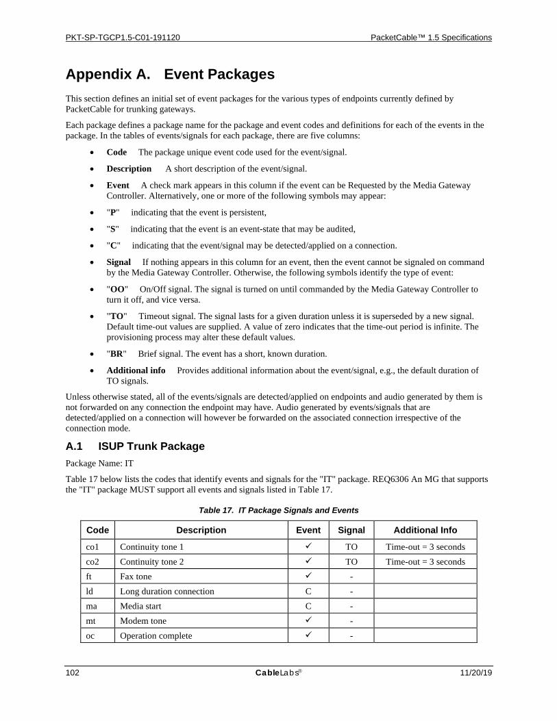
PKT-SP-TGCP1.5-C01-191120 PacketCable™ 1.5 Specifications
102 CableLabs 11/20/19
Appendix A. Event Packages This section defines an initial set of event packages for the various types of endpoints currently defined by PacketCable for trunking gateways.
Each package defines a package name for the package and event codes and definitions for each of the events in the package. In the tables of events/signals for each package, there are five columns:
• Code The package unique event code used for the event/signal.
• Description A short description of the event/signal.
• Event A check mark appears in this column if the event can be Requested by the Media Gateway Controller. Alternatively, one or more of the following symbols may appear:
• "P" indicating that the event is persistent,
• "S" indicating that the event is an event-state that may be audited,
• "C" indicating that the event/signal may be detected/applied on a connection.
• Signal If nothing appears in this column for an event, then the event cannot be signaled on command by the Media Gateway Controller. Otherwise, the following symbols identify the type of event:
• "OO" On/Off signal. The signal is turned on until commanded by the Media Gateway Controller to turn it off, and vice versa.
• "TO" Timeout signal. The signal lasts for a given duration unless it is superseded by a new signal. Default time-out values are supplied. A value of zero indicates that the time-out period is infinite. The provisioning process may alter these default values.
• "BR" Brief signal. The event has a short, known duration.
• Additional info Provides additional information about the event/signal, e.g., the default duration of TO signals.
Unless otherwise stated, all of the events/signals are detected/applied on endpoints and audio generated by them is not forwarded on any connection the endpoint may have. Audio generated by events/signals that are detected/applied on a connection will however be forwarded on the associated connection irrespective of the connection mode.
A.1 ISUP Trunk Package Package Name: IT
Table 17 below lists the codes that identify events and signals for the "IT" package. REQ6306 An MG that supports the "IT" package MUST support all events and signals listed in Table 17.
Table 17. IT Package Signals and Events
Code Description Event Signal Additional Info
co1 Continuity tone 1 TO Time-out = 3 seconds co2 Continuity tone 2 TO Time-out = 3 seconds ft Fax tone - ld Long duration connection C - ma Media start C - mt Modem tone - oc Operation complete -
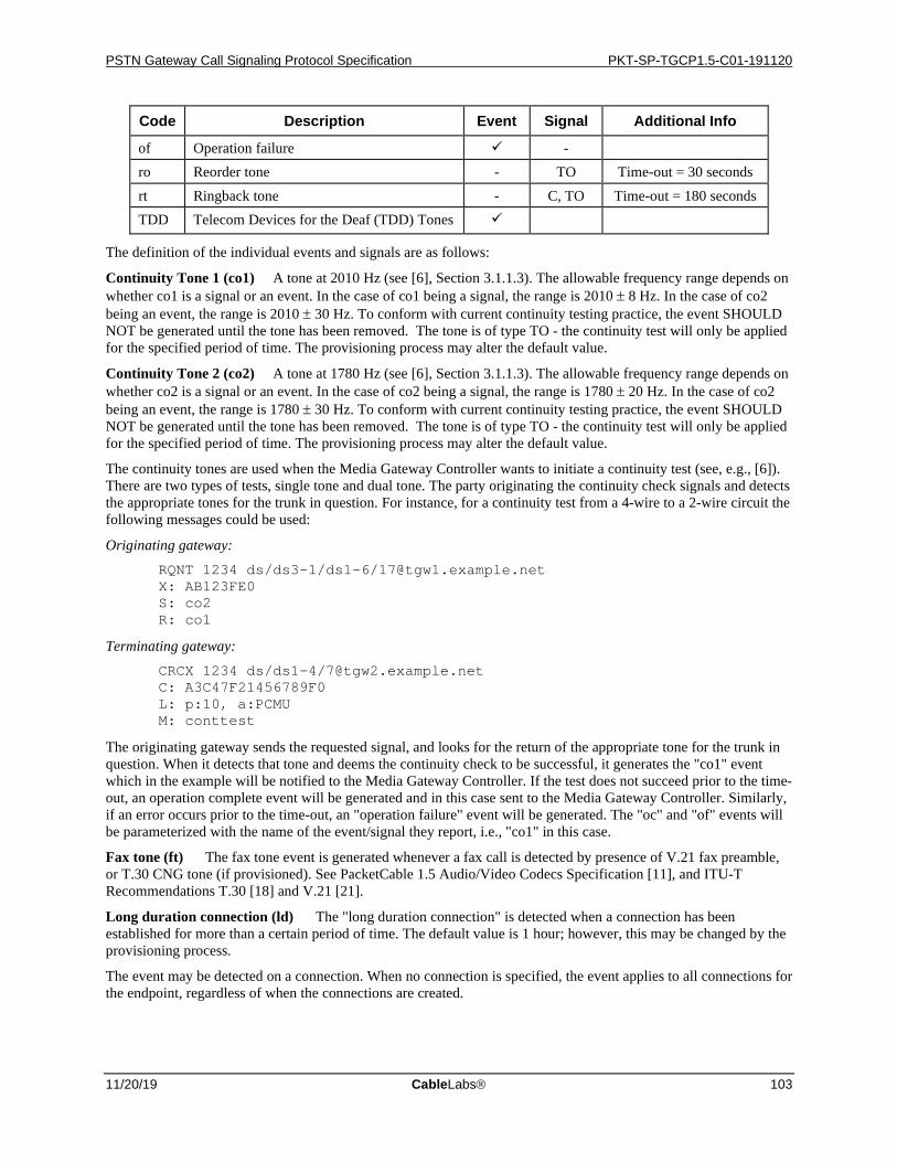
PSTN Gateway Call Signaling Protocol Specification PKT-SP-TGCP1.5-C01-191120
11/20/19 CableLabs 103
Code Description Event Signal Additional Info
of Operation failure - ro Reorder tone - TO Time-out = 30 seconds rt Ringback tone - C, TO Time-out = 180 seconds TDD Telecom Devices for the Deaf (TDD) Tones
The definition of the individual events and signals are as follows:
Continuity Tone 1 (co1) A tone at 2010 Hz (see [6], Section 3.1.1.3). The allowable frequency range depends on whether co1 is a signal or an event. In the case of co1 being a signal, the range is 2010 ± 8 Hz. In the case of co2 being an event, the range is 2010 ± 30 Hz. To conform with current continuity testing practice, the event SHOULD NOT be generated until the tone has been removed. The tone is of type TO - the continuity test will only be applied for the specified period of time. The provisioning process may alter the default value.
Continuity Tone 2 (co2) A tone at 1780 Hz (see [6], Section 3.1.1.3). The allowable frequency range depends on whether co2 is a signal or an event. In the case of co2 being a signal, the range is 1780 ± 20 Hz. In the case of co2 being an event, the range is 1780 ± 30 Hz. To conform with current continuity testing practice, the event SHOULD NOT be generated until the tone has been removed. The tone is of type TO - the continuity test will only be applied for the specified period of time. The provisioning process may alter the default value.
The continuity tones are used when the Media Gateway Controller wants to initiate a continuity test (see, e.g., [6]). There are two types of tests, single tone and dual tone. The party originating the continuity check signals and detects the appropriate tones for the trunk in question. For instance, for a continuity test from a 4-wire to a 2-wire circuit the following messages could be used:
Originating gateway: RQNT 1234 ds/ds3-1/ds1-6/[email protected] X: AB123FE0 S: co2 R: co1
Terminating gateway: CRCX 1234 ds/ds1-4/[email protected] C: A3C47F21456789F0 L: p:10, a:PCMU M: conttest
The originating gateway sends the requested signal, and looks for the return of the appropriate tone for the trunk in question. When it detects that tone and deems the continuity check to be successful, it generates the "co1" event which in the example will be notified to the Media Gateway Controller. If the test does not succeed prior to the time-out, an operation complete event will be generated and in this case sent to the Media Gateway Controller. Similarly, if an error occurs prior to the time-out, an "operation failure" event will be generated. The "oc" and "of" events will be parameterized with the name of the event/signal they report, i.e., "co1" in this case.
Fax tone (ft) The fax tone event is generated whenever a fax call is detected by presence of V.21 fax preamble, or T.30 CNG tone (if provisioned). See PacketCable 1.5 Audio/Video Codecs Specification [11], and ITU-T Recommendations T.30 [18] and V.21 [21].
Long duration connection (ld) The "long duration connection" is detected when a connection has been established for more than a certain period of time. The default value is 1 hour; however, this may be changed by the provisioning process.
The event may be detected on a connection. When no connection is specified, the event applies to all connections for the endpoint, regardless of when the connections are created.
PKT-SP-TGCP1.5-C01-191120 PacketCable™ 1.5 Specifications
104 CableLabs 11/20/19
Media start (ma) The media start event occurs on a connection when the first valid27 RTP media packet is received on the connection. This event can be used to synchronize a local signal, e.g., ringback, with the arrival of media from the other party.
The event may be detected on a connection. When no connection is specified, the event applies to all connections for the endpoint, regardless of when the connections are created.
Modem tone (mt) The modem tone event is generated whenever a data call is detected by presence of V.25 answer tone (ANS) with or without phase reversal or V.8 modified answer tone (ANSam) with or without phase reversal. See [22] and [19].
Operation complete (oc) The operation complete event is generated when the gateway was asked to apply one or several signals of type TO on the endpoint, and one or more of those signals completed without being stopped by the detection of a requested event such as "continuity tone 1". The completion report may carry as a parameter the name of the signal that came to the end of its live time, as in:
O: IT/oc(IT/co1)
When the reported signal was applied on a connection, the parameter supplied will include the name of the connection as well, as in:
O: IT/oc(IT/rt@0A3F58)
When the operation complete event is requested, it cannot be parameterized with any event parameters. When the package name is omitted, the default package name is assumed.
The operation complete event may additionally be generated as defined in the base protocol, e.g., when an embedded ModifyConnection command completes successfully, as in: O: IT/oc(B/C)
Note the use of "B" above as the prefix for the parameter reported.
27 When authentication and integrity security services are used, an RTP packet is not considered valid until it has passed the security checks.

PSTN Gateway Call Signaling Protocol Specification PKT-SP-TGCP1.5-C01-191120
11/20/19 CableLabs 105
Operation failure (of) In general, the operation failure event may be generated when the endpoint was asked to apply one or several signals of type TO on the endpoint, and one or more of those signals failed prior to timing out. The completion report may carry as a parameter the name of the signal that failed, as in:
O: IT/of(IT/co2)
When the reported signal was applied on a connection, the parameter supplied will include the name of the connection as well, as in:
O: IT/of(IT/rt@0A3F58)
When the operation failure event is requested, event parameters cannot be specified. When the package name is omitted, the default package name is assumed.
The operation failure event may additionally be generated as specified in the base protocol, e.g., when an embedded ModifyConnection command fails, as in: O: IT/of(B/C(M(sendrecv(AB2354))))
Note the use of "B" above as the prefix for the parameter reported.
Reorder tone (ro) Reorder tone is a combination of two AC tones with frequencies of 480 and 620 Hertz and levels of -24 dBm each, to give a combined level of -21 dBm. The cadence for reorder tone is 0.25 seconds on followed by 0.25 seconds off, repeating continuously. See [9], Section 17.2.7.
Ring back tone (rt) Audible Ring Tone is a combination of two AC tones with frequencies of 440 and 480 Hertz and levels of –19 dBm each, to give a combined level of –16 dBm. In the U.S. the cadence for Audible Ring Tone is defined to be 2 seconds on followed by 4 seconds off. The definition of the tone is defined by the national characteristics of the Ringback Tone, and MAY be established via provisioning. See [9], Section 17.2.5.
The ringback signal can be applied to both an endpoint and a connection.
Telecomm Devices for the Deaf tones (TDD) The TDD event is generated whenever a TDD communication is detected – see [20].
A.2 MF FGD Operator Services Package Package name: MO
The codes listed in Table 18 below are used to identify events and signals for the "MO" package for one-way outgoing MF FGD Operator Services trunks – see [7], "Operator Services Signaling". MF FGC Operator Services signaling is supported as well. The difference between FGC and FGD Operator Services signaling simply lies in the number of ANI Information digits. This package will be used for general operator service trunks as well as dedicated E911 trunks. An MG that supports the "MO" package MUST support all events and signals listed in Table 18.
Table 18. MO Package Signals and Events
Code Description Event Signal Additional Info
Ans Call Answer P - Ft Fax tone - ld Long duration connection C - Mt Modem tone - Orbk Operator Ringback - Rbz Reverse make busy P - Rcl Operator Recall - BR Rel Release Call P BR
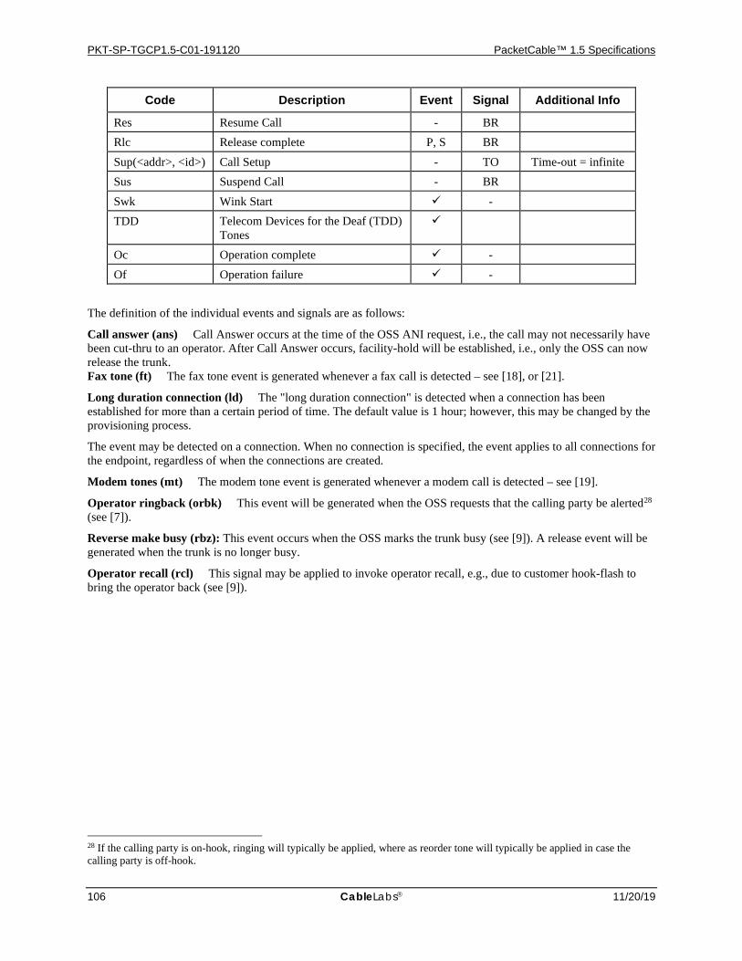
PKT-SP-TGCP1.5-C01-191120 PacketCable™ 1.5 Specifications
106 CableLabs 11/20/19
Code Description Event Signal Additional Info
Res Resume Call - BR Rlc Release complete P, S BR Sup(<addr>, <id>) Call Setup - TO Time-out = infinite Sus Suspend Call - BR Swk Wink Start - TDD Telecom Devices for the Deaf (TDD)
Tones
Oc Operation complete - Of Operation failure -
The definition of the individual events and signals are as follows:
Call answer (ans) Call Answer occurs at the time of the OSS ANI request, i.e., the call may not necessarily have been cut-thru to an operator. After Call Answer occurs, facility-hold will be established, i.e., only the OSS can now release the trunk. Fax tone (ft) The fax tone event is generated whenever a fax call is detected – see [18], or [21].
Long duration connection (ld) The "long duration connection" is detected when a connection has been established for more than a certain period of time. The default value is 1 hour; however, this may be changed by the provisioning process.
The event may be detected on a connection. When no connection is specified, the event applies to all connections for the endpoint, regardless of when the connections are created.
Modem tones (mt) The modem tone event is generated whenever a modem call is detected – see [19].
Operator ringback (orbk) This event will be generated when the OSS requests that the calling party be alerted28 (see [7]).
Reverse make busy (rbz): This event occurs when the OSS marks the trunk busy (see [9]). A release event will be generated when the trunk is no longer busy.
Operator recall (rcl) This signal may be applied to invoke operator recall, e.g., due to customer hook-flash to bring the operator back (see [9]).
28 If the calling party is on-hook, ringing will typically be applied, where as reorder tone will typically be applied in case the calling party is off-hook.

PSTN Gateway Call Signaling Protocol Specification PKT-SP-TGCP1.5-C01-191120
11/20/19 CableLabs 107
Release call (rel) Release call can either be a signal or event depending on the direction in which release is initiated. If no facility-hold is in affect for the trunk, and onhook is initiated by the subscriber line, then the Media Gateway Controller should send a release call signal to the Media Gateway. However, if facility-hold is in affect for the trunk, and onhook is initiated by the subscriber line, then the Media Gateway Controller should send a suspend signal to the Media Gateway (i.e., a release call signal should not be generated in this case).
A release call event should be generated by the Media Gateway when the OSS initiates a "release call". In this case the event may be parameterized with one of the following cause codes indicating the reason for the release. The list of cause codes is provided in Table 19 below.
Table 19. Cause codes for the Release Call Event
Cause Code Reason 0 Normal release 3 No route to destination 8 Preemption
19 No answer 21 Call rejected 27 Destination out of order 28 Invalid number format (e.g., address incomplete) 38 Network out of order
111 Protocol/signaling error, unspecified (e.g., timeout) Resume call (res) This signal indicates that the other party resumed the call, i.e., the party went off-hook. If facility-hold is in affect for the trunk, and offhook is initiated by the subscriber line of a suspended call, then the Media Gateway Controller should send a resume signal to the Media Gateway.
Release complete (rlc) The Media Gateway and Media Gateway Controller use the release complete event/signal to confirm the call has been released and the trunk is available for another call. The release complete event/signal should always be generated as a response to a release event/signal, and therefore, should not be generated as an unsolicited event/signal. In the event an unsolicited release complete event/signal is received, the call should be released, and trunk made available for another call.
Call setup (sup(<addr>, <id>)) Call setup is a unique consolidation of trunk seizure and both stages of digit outpulsing, and therefore, MUST NOT be cancelled by the occurrence of MO/swk or MO/ans events. Although a time-out signal, call setup time-out MUST be infinite. The MG MUST send either a MO/oc (for success) or MO/of (for failure) event to signify its completion. The MO/oc event MUST occur upon successful completion of outpulsing of last stage of digits, otherwise MO/of event MUST occur. Call setup to the operator service system MUST use the following address and identification information.
Address information MUST be of the form:
addr(MF1, MF2, …, MFn)
Identification information MUST be of the form:
id(MF1, MF2, …, MFn)
Each of MFi MUST be one of the following MF digit symbols identified in Table 20 below.

PKT-SP-TGCP1.5-C01-191120 PacketCable™ 1.5 Specifications
108 CableLabs 11/20/19
Table 20. Symbols Representing MF Digits - MF FGD Operator Services Package
Symbol MF digit 0 MF 0 1 MF 1 2 MF 2 3 MF 3 4 MF 4 5 MF 5 6 MF 6 7 MF 7 8 MF 8 9 MF 9 K0 MF K0 or KP K1 MF K1 K2 MF K2 S0 MF S0 or ST S1 MF S1 S2 MF S2 S3 MF S3
Thus, an example call setup signal could be:
sup(addr(K0, 5,5,5,1,2,1,2, SO), id(K0, 5,5,5,1,2,3,4, SO))
Suspend call (sus) This signal indicates that the other party suspended the call, i.e., the party went on-hook. If facility-hold is in affect for the trunk, and onhook is initiated by the subscriber line, then the Media Gateway Controller should send a suspend signal to the Media Gateway. However, if no facility-hold is in affect for the trunk, and onhook is initiated by the subscriber line, then the Media Gateway Controller should generate a release call signal to the Media Gateway (i.e., a suspend call signal should not be generated in this case).
Start Wink (swk) A Media Gateway Controller can request the Media Gateway to notify it when the wink start signal occurs.
Telecomm Devices for the Deaf tones (TDD) The TDD event is generated whenever a TDD call is detected – see [20].
Operation complete (oc) The operation complete event is generated when the gateway was asked to apply one or several signals of type TO on the endpoint, and one or more of those signals completed without being stopped by the detection of a requested event such as off-hook transition or dialed digit. The completion report may carry as a parameter the name of the signal that came to the end of its live time, as in:
O: MO/oc(MO/sup)
When the operation complete event is requested, it cannot be parameterized with any event parameters. When the package name is omitted, the default package name is assumed.
Operation failure (of) In general, the operation failure event may be generated when the endpoint was asked to apply one or several signals of type TO on the endpoint, and one or more of those signals failed prior to timing out. The completion report may carry as a parameter the name of the signal that failed, as in:
O: MO/of(MO/sup)
When the operation failure event is requested, event parameters cannot be specified. When the package name is omitted, the default package name is assumed.
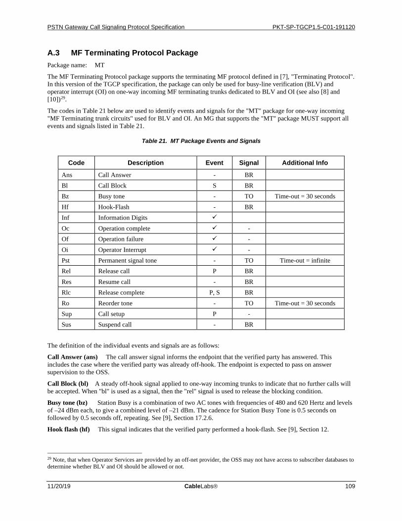
PSTN Gateway Call Signaling Protocol Specification PKT-SP-TGCP1.5-C01-191120
11/20/19 CableLabs 109
A.3 MF Terminating Protocol Package Package name: MT
The MF Terminating Protocol package supports the terminating MF protocol defined in [7], "Terminating Protocol". In this version of the TGCP specification, the package can only be used for busy-line verification (BLV) and operator interrupt (OI) on one-way incoming MF terminating trunks dedicated to BLV and OI (see also [8] and [10])29.
The codes in Table 21 below are used to identify events and signals for the "MT" package for one-way incoming "MF Terminating trunk circuits" used for BLV and OI. An MG that supports the "MT" package MUST support all events and signals listed in Table 21.
Table 21. MT Package Events and Signals
Code Description Event Signal Additional Info
Ans Call Answer - BR Bl Call Block S BR Bz Busy tone - TO Time-out = 30 seconds Hf Hook-Flash - BR Inf Information Digits Oc Operation complete - Of Operation failure - Oi Operator Interrupt - Pst Permanent signal tone - TO Time-out = infinite Rel Release call P BR Res Resume call - BR Rlc Release complete P, S BR Ro Reorder tone - TO Time-out = 30 seconds Sup Call setup P - Sus Suspend call - BR
The definition of the individual events and signals are as follows:
Call Answer (ans) The call answer signal informs the endpoint that the verified party has answered. This includes the case where the verified party was already off-hook. The endpoint is expected to pass on answer supervision to the OSS.
Call Block (bl) A steady off-hook signal applied to one-way incoming trunks to indicate that no further calls will be accepted. When "bl" is used as a signal, then the "rel" signal is used to release the blocking condition.
Busy tone (bz) Station Busy is a combination of two AC tones with frequencies of 480 and 620 Hertz and levels of –24 dBm each, to give a combined level of –21 dBm. The cadence for Station Busy Tone is 0.5 seconds on followed by 0.5 seconds off, repeating. See [9], Section 17.2.6.
Hook flash (hf) This signal indicates that the verified party performed a hook-flash. See [9], Section 12.
29 Note, that when Operator Services are provided by an off-net provider, the OSS may not have access to subscriber databases to determine whether BLV and OI should be allowed or not.

PKT-SP-TGCP1.5-C01-191120 PacketCable™ 1.5 Specifications
110 CableLabs 11/20/19
Information Digits (inf(<inf-digits>) Used on an incoming MF trunk to indicate digits received. The parameter value <inf-digits> are all of the digits accumulated up to and including the digit delimiter, i.e., ST, ST', ST'', or ST'''.
The value of <inf-digits> is a comma separated list of MF digits:
MF1, MF2, …, MFn
where each of MFi will be one of the following MF digit symbols listed in Table 22.
Table 22. Symbols Representing MF digits - MF Terminating Protocol Package
Symbol MF digit 0 MF 0 1 MF 1 2 MF 2 3 MF 3 4 MF 4 5 MF 5 6 MF 6 7 MF 7 8 MF 8 9 MF 9 K0 MF K0 or KP K1 MF K1 K2 MF K2 S0 MF S0 or ST S1 MF S1 S2 MF S2 S3 MF S3
Thus, an example signal or event might look like:
inf(k0, 5,5,5,1,2,3,4, s0)
An example where the inter-digit timer expired after the 5,5,5 would appear as follows:
inf(k0, 5,5,5)
Operation complete (oc) See the definition of "operation complete" in the ISUP trunk package.
Operation failure (of) See the definition of "operation failure" in the ISUP trunk package.
Operator Interrupt (oi) The operator interrupt event occurs when the operator attempts to interrupt the call and generates the "operator interrupt" tone. Since no standard tone is defined for this, the event is here defined to occur when a certain level of energy is detected on the trunk corresponding to a transition from line noise to voice or tones. It should be noted, that it is hereby not possible to detect a transition back to line noise from voice/tones.
Permanent signal tone (pst) See [8].
Release call (rel) Release call can either be a signal or event depending on the direction in which release is initiated. If no facility-hold is in affect for the trunk, and onhook is initiated by the subscriber line, then the Media Gateway Controller should send a release call signal to the Media Gateway. However, if facility-hold is in affect for the trunk, and onhook is initiated by the subscriber line, then the Media Gateway Controller should send a suspend signal to the Media Gateway (i.e., a release call signal should not be generated in this case). Note, the release call signal is not expected to be utilized by BLV and OI.
A release call event should be generated by the Media Gateway when the OSS initiates a "release call". In this case the event may be parameterized with one of the following cause codes indicating the reason for the release. The list of cause codes that may be used is provided in Table 23 below.
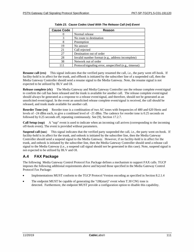
PSTN Gateway Call Signaling Protocol Specification PKT-SP-TGCP1.5-C01-191120
11/20/19 CableLabs 111
Table 23. Cause Codes Used With The Release Call (rel) Event
Cause Code Reason 0 Normal release 3 No route to destination 8 Preemption
19 No answer 21 Call rejected 27 Destination out of order 28 Invalid number format (e.g., address incomplete) 38 Network out of order
111 Protocol/signaling error, unspecified (e.g., timeout) Resume call (res) This signal indicates that the verified party resumed the call, i.e., the party went off-hook. If facility-hold is in affect for the trunk, and offhook is initiated by the subscriber line of a suspended call, then the Media Gateway Controller should send a resume signal to the Media Gateway. Note, the resume signal is not expected to be utilized by BLV and OI.
Release complete (rlc) The Media Gateway and Media Gateway Controller use the release complete event/signal to confirm the call has been released and the trunk is available for another call. The release complete event/signal should always be generated as a response to a release event/signal, and therefore, should not be generated as an unsolicited event/signal. In the event an unsolicited release complete event/signal is received, the call should be released, and trunk made available for another call.
Reorder Tone (ro) Reorder tone is a combination of two AC tones with frequencies of 480 and 620 Hertz and levels of –24 dBm each, to give a combined level of –21 dBm. The cadence for reorder tone is 0.25 seconds on followed by 0.25 seconds off, repeating continuously. See [9], Section 17.2.7.
Call Setup (sup) A "sup" event is used to indicate when an incoming call arrives (corresponding to the incoming off-hook event). The event is provided without parameters.
Suspend call (sus) This signal indicates that the verified party suspended the call, i.e., the party went on-hook. If facility-hold is in affect for the trunk, and onhook is initiated by the subscriber line, then the Media Gateway Controller should send a suspend signal to the Media Gateway. However, if no facility-hold is in affect for the trunk, and onhook is initiated by the subscriber line, then the Media Gateway Controller should send a release call signal to the Media Gateway (i.e., a suspend call signal should not be generated in this case). Note, suspend signal is not expected to be utilized by BLV and OI.
A.4 FAX Package The following Media Gateway Control Protocol Fax Package defines a mechanism to support FAX calls. TGCP imposes the following additional requirements above and beyond those specified in the Media Gateway Control Protocol Fax Package:
• Implementations MUST conform to the TGCP Protocol Version encoding as specified in Section 8.2.1.4
• The endpoint MUST be capable of generating the "t38(start)" event when T.30 CNG tone is detected. Furthermore, the endpoint MUST provide a configuration option to disable this capability.

PKT-SP-TGCP1.5-C01-191120 PacketCable™ 1.5 Specifications
112 CableLabs 11/20/19
Media Gateway Control Protocol Fax Package Abstract This document defines a Media Gateway Control Protocol (MGCP) package to support fax calls. The package allows for fax calls to be supported in two different ways. The first one utilizes ITU-T Recommendation T.38 for fax relay under the control of the Call Agent. The second one lets the gateway decide upon a method for fax transmission as well as handle the details of the fax call without Call Agent involvement. Conventions used in this document The key words "MUST", "MUST NOT", "REQUIRED", "SHALL", "SHALL NOT", "SHOULD", "SHOULD NOT", "RECOMMENDED", "MAY", and "OPTIONAL" in this document are to be interpreted as described in BCP 14, RFC-2119 [RFC2119]. Table of Contents 1. Introduction 2. Fax Package Definition 2.1 LocalConnectionOptions 2.1.1 T.38 Procedure (Strict or Loose) 2.1.2 Gateway Procedure 2.1.3 Off Procedure 2.1.4 Mode Operation 2.1.5 Detecting a Fax Call 2.1.6 Considerations for Which Procedures to Request 2.2 Events and Signals 2.2.1 Gateway Controlled Fax (gwfax) 2.2.2 No Special Fax Handling (nopfax) 2.2.3 T.38 fax relay(t38): 2.3 Connection Parameters 2.4 Negotiation of T.38 Parameters 2.5 Implementation Considerations 2.5.1 Media IP Address and Port for T.38 2.5.2 Case Sensitivity 2.5.3 Boolean Indicator after T.38 Parameters 3. Call Flow Examples 3.1 Call Agent Controlled T.38 Strict 3.2 Multiple and Different Options 3.3 Interaction with SIP Endpoints 4. Security Considerations 5. IANA Considerations 6. Normative References 7. Informative References 8. Acknowledgements 9. Author's Address 1. INTRODUCTION
PSTN Gateway Call Signaling Protocol Specification PKT-SP-TGCP1.5-C01-191120
11/20/19 CableLabs 113
This document defines a Media Gateway Control Protocol (MGCP) [RFC3435] package that enables MGCP controlled gateways to support fax calls. The package enables fax calls to be supported in two different ways. The first one utilizes ITU-T Recommendation T.38 using either UDPTL or TCP (see [T38]) for fax relay under the control of the Call Agent. The second one lets the gateway decide upon a method for fax transmission as well as handle the details of the fax call without Call Agent involvement. The fax package definition is provided in Section 2 and in Section 3 we provide two call flow examples showing how to use it. Security considerations are found in Section 4, followed by the IANA considerations and references. 2. FAX PACKAGE DEFINITION A package is defined for fax. The package defines new localconnectionoptions, events, and connection parameters as detailed below. Package Name: FXR Package Version: 0 2.1 LocalConnectionOptions A new Fax LocalConnectionOptions (LCO) parameter is defined for fax handling. The Call Agent supplies this fax LCO to indicate the desired fax handling procedure to the Media Gateway. The fax LCO contains a list of desired fax handling procedures ordered by preference with the most desired procedure listed first. When the parameter is explicitly included in a command, the gateway MUST be able to use at least one of the listed procedures for the command to succeed. The list can currently indicate one or more of the following procedures (see Section 2.1.1 to 2.1.4 for further details on these): * T.38 Strict Use T.38 [T38] with either UDPTL or TCP for fax relay and have the Call Agent control it. Assuming the procedure can be used (see Section 2.1.1), a switch to T.38 procedures will be initiated upon fax detection and a "t38(start)" event will be generated (see Section 2.2). This mode requires an indication of T.38 support from the remote side in order to be used, as described further in Section 2.1.1. * T.38 Loose Identical to T.38 Strict procedure, except that an indication of T.38 support from the remote side is not required for the procedure to be used. * Off Do not invoke any special procedure for fax, except for echo cancellation adjustment and possibly switching to another codec. * Gateway Let the gateway control and decide how to handle fax calls without Call Agent involvement. This includes the case where the gateway does not do anything special for fax, hence by definition this procedure can always be supported. If the gateway does invoke a special procedure upon detection of fax, it will generate a "gwfax(start)" event so the Call Agent can be notified about it (see Section 2.2). The Call Agent SHOULD then refrain from issuing potentially conflicting commands to the gateway until the gateway ends its special fax handling procedure. A gateway that ends up not being able to invoke any special procedure for fax will generate a "nopfax(start)" event (see Section 2.2) upon detection of fax.
PKT-SP-TGCP1.5-C01-191120 PacketCable™ 1.5 Specifications
114 CableLabs 11/20/19
The set of possible values (i.e., procedures) for the fax LCO is extensible. The prefix "x-", which indicates an optional extension, and the prefix "x+", which indicates a mandatory extension, are reserved for vendor-specific use. In CreateConnection commands, the fax LCO value defaults to "gateway". In ModifyConnection commands, the fax LCO value defaults to its current value on the connection. Thus, if LocalConnectionOptions are either omitted or the fax LCO is not included in a ModifyConnection command, the previous fax LCO value for the connection is retained, but without affecting the outcome of the command; consequently, the gateway may now not apply any special procedure to fax. If the Call Agent wants to ensure that a command succeeds only when a fax procedure is applied, the command needs to include the fax LCO explicitly. As an example of this, assume that the CreateConnection command successfully specified the use of "T.38 Strict", and a ModifyConnection command is now received without the fax LCO, but with a RemoteConnectionDescriptor indicating no support for T.38; in that case, the ModifyConnection command will succeed, however T.38 procedures will no longer be invoked upon fax detection. Had the Call Agent instead included the fax LCO set to "T.38 Strict", the command would have failed. If multiple fax parameter values are provided, the gateway MUST choose one of the procedures specified according to the order in which they are supplied, except as follows: 1. If "gateway" would have been selected and it would have resulted in no special
procedure being applied, and 2. there are other procedures than "off" which are specified after "gateway" (e.g.,
"t38") then the gateway MUST use the most preferred of those subsequent procedures that can be supported. If none of those subsequent procedures can be supported, the gateway reverts to not invoking any special procedure for fax. Please refer to Section 2.1.4 for further details on determining which procedures can be supported. The fax LCO parameter is encoded as the keyword "fx" (prefixed with the package name per [RFC3435]), followed by a colon and a semicolon separated list of values where T.38 Strict is encoded as "t38", T.38 Loose is encoded as "t38-loose", gateway is encoded as "gw", and off is encoded as "off". The following example illustrates use of PCMU or G.729 for audio encoding and T.38 Strict fax relay (preferred) or gateway control for fax: L: a:PCMU;G729, fxr/fx:t38;gw It should be noted, that MGCP allows the CreateConnection command to omit both LocalConnectionOptions and a RemoteConnectionDescriptor thereby letting the gateway decide upon the media parameters to use. When the T.38 fax package is supported, the gateway thus could choose to do either audio or T.38 fax relay in such cases. Most likely, the Call Agent requires one or the other to be used, and hence it SHOULD NOT omit both LocalConnectionOptions and a RemoteConnectionDescriptor in CreateConnection commands.
PSTN Gateway Call Signaling Protocol Specification PKT-SP-TGCP1.5-C01-191120
11/20/19 CableLabs 115
When auditing capabilities, the fax LCO may be returned with a semi-colon separated list of supported fax handling parameters. The values "t38", t38-loose, "off" and "gw" MAY be omitted from such a list as they are always implied. Gateways that implement additional parameters SHOULD return these additional parameters when capabilities are audited as illustrated by the following example: A: a:image/t38, fxr/fx:mypar, ... In the following subsections we provide additional detail on the above defined fax procedures. 2.1.1 T.38 Procedure (Strict or Loose) When a gateway is instructed to use one of the T.38 procedures (strict or loose), also known as Call Agent controlled T.38 mode, the "m=" line in the SDP returned will not indicate use of UDPTL-based or TCP-based T.38 (unless the gateway was also instructed to use "image/t38" for the media stream). Any other entity seeing this SDP will not know whether T.38 is supported or not and hence whether it is safe to attempt a switch to T.38 upon fax detection. To remedy this dilemma, capability information for T.38 (if supported) using the SDP Simple Capability Declaration extensions [RFC3407] MUST be included. Other capability information is included as well, regardless of whether the Call Agent authorized use of those in the connection handling command or not. A subsequent attempt to actually use these may of course not succeed, e.g., because the Call Agent LCOs does not allow them to be used. The following example illustrates the RFC 3407 capability descriptor – note the inclusion of both current (audio) and latent (T.38) capabilities as specified in RFC 3407: m=audio 3456 RTP/AVP 18 a=sqn: 0 a=cdsc: 1 audio RTP/AVP 18 a=cdsc: 2 image udptl t38 For a list of T.38 related parameters to be included in the SDP, please refer to T.38 Annex D [T38]. Upon fax detection, a gateway which has successfully been instructed to use one of the T.38 procedures will: 1. Initiate the T.38 fax relay procedure and mute the media channel in both the send
and receive direction (unless the media channel is already using T.38). 2. Generate a "t38(start)" event. 3. Await further instructions from the Call Agent in order to initiate the actual media change (unless the media channel is already using T.38).
PKT-SP-TGCP1.5-C01-191120 PacketCable™ 1.5 Specifications
116 CableLabs 11/20/19
The Call Agent instructs the gateway to perform the media change by sending it a ModifyConnection command with "image/t38" listed as the encoding method in the LocalConnectionOptions (receipt of a ModifyConnection command without LocalConnectionOptions but with a RemoteConnectionDescriptor containing an "m=" line with the MIME type "image/t38" would achieve the same). Per the normal MGCP codec negotiation procedures (see [RFC3435] Section 2.6), if a RemoteConnectionDescriptor was included as well, it needs to include an "m=" line with "image/t38" as an acceptable media format in order for the command to succeed. The gateway may choose between the UDPTL and TCP transport protocols at its own discretion subject to the normal MGCP codec negotiation procedures (in practice, TCP-based implementations are currently rare). If a RemoteConnectionDescriptor was not included with the ModifyConnection command sent to a gateway that initiated the T.38 procedure, it is possible (in fact likely), that the last received RemoteConnectionDescriptor did not include an "m=" line listing "image/t38" as an acceptable media format. In that case, the endpoint cannot send T.38 media to the other side. The endpoint MUST instead wait for an updated RemoteConnectionDescriptor with "image/t38" as an acceptable media format and a supported transport protocol (UDPTL or TCP). The T.38 fax procedure continues when an acceptable RemoteConnectionDescriptor is received. An acceptable RemoteConnectionDescriptor contains an "m=" line with the "image/t38" MIME type (using the normal SDP syntax) and a supported transport protocol (UDPTL or TCP). If the fax call fails, e.g., due to a fax timeout, while either waiting for the Call Agent to instruct the gateway to switch to "image/t38" or waiting for an acceptable RemoteConnectionDescriptor, a "t38(stop)" or a "t38(failure)" event MUST be generated. When the T.38 procedure ends, a "t38(stop)" or "t38(failure)" event MUST be generated. Finally, the Call Agent may need to abort a T.38 procedure that is in progress. This can for example be done when the remote side was unable to switch to T.38, and a fallback to fax passthrough using an audio codec is attempted. The Call Agent instructs the endpoint to abort an in-progress T.38 procedure by use of the "off" Fax LCO as illustrated below: L: fxr/fx:off We now define "time t38init" as the point in time where the T.38 procedure was initiated, and "time t38abort" as the point in time where the Call Agent aborts an in-progress T.38 procedure. If the Call Agent at time t38abort instructs or enables the endpoint to revert to one or more codecs that were in use just prior to time t38init, the endpoint SHOULD use media stream parameters that mimic the most recent LocalConnectionDescriptor issued before time t38init. For example, IP-address and UDP port, payload formats used and their payload type mapping, should all be the same as before time t38init. This will enable the fallback to be as rapid as possible. A LocalConnectionDescriptor is returned as usual, i.e., only if one or more parameters changed since the last LocalConnectionDescriptor issue (e.g., if a T.38 LCD was issued or a transport address in the audio LCD was changed). 2.1.2 Gateway Procedure
PSTN Gateway Call Signaling Protocol Specification PKT-SP-TGCP1.5-C01-191120
11/20/19 CableLabs 117
A gateway using the gateway procedure, also known as Gateway controlled mode, may initiate special fax handling upon detecting a fax call. The details of this special fax handling are outside the scope of this document. However, in order to use any special fax handling, support for it MUST be negotiated with the other side by passing and recognizing relevant parameters via the LocalConnectionDescriptor and RemoteConnectionDescriptor. If the other side has not indicated support for the special fax handling desired, the gateway MUST NOT attempt to initiate it. When special fax handling is initiated, a "gwfax(start)" event MUST be generated thereby enabling the Call Agent to differ between the Call Agent and gateway controlled mode while still being informed about the actual change to fax. When the special gateway handling of fax ends, a "gwfax(stop)" or "gwfax(failure)" event MUST be generated. 2.1.3 Off Procedure A gateway using the "off" procedure will not invoke any special fax procedures, e.g., T.38, when detecting a fax. However, the gateway may still adjust local echo cancellation and/or switch to an alternative codec as needed (in particular, this does not preclude the use of RTP-based T.38). Also, a "nopfax(start)" event MUST be generated; a corresponding "stop" event however will not. Generating a "stop" event would imply that the gateway had to infer when the fax call ends, which involves processing of the media stream. However, when using the "off" mode, such processing is not expected to occur. 2.1.4 Mode Operation For each of the above modes, the RemoteConnectionDescriptor provides information on what procedure(s) the other side supports. The following rules are used to determine which procedure to use: 1. Whatever the Call Agent specified in the Fax LocalConnectionOptions for the current
command MUST be adhered to. If the gateway cannot satisfy any of the options, the command fails (error code 532 - unsupported value(s) in LocalConnectionOptions is RECOMMENDED).
2. If both Fax LocalConnectionOptions and a RemoteConnectionDescriptor are provided,
the procedure selected MUST be supported by both sides - this is currently only an issue for "T.38 Strict". A procedure can be satisfied by the remote side if:
* the relevant MIME media type, e.g., "image/t38", is included in the "m=" line in the RemoteConnectionDescriptor, or * the relevant MIME media type is included as a capability (see [RFC3407]) in the RemoteConnectionDescriptor. If the gateway cannot select any of the procedures in the Fax LocalConnectionOptions, the command fails (error code 532 is RECOMMENDED). Note that "T.38 Loose", "gateway", and "off" by definition can always be supported by an implementation that supports this package, irrespective of what the RemoteConnectionDescriptor indicates. 3. If the Call Agent did not include any Fax LocalConnectionOptions or a
RemoteConnectionDescriptor with the command, the gateway MUST continue using whichever procedure it is currently using.
PKT-SP-TGCP1.5-C01-191120 PacketCable™ 1.5 Specifications
118 CableLabs 11/20/19
4. If the Call Agent did not include any Fax LocalConnectionOptions, but a RemoteConnectionDescriptor was included, the gateway MUST follow rule 2 in selecting a procedure. In so doing, the default Fax LocalConnectionOptions, i.e., "gateway" in CreateConnection, or the current value in ModifyConnection, MUST be used. In the case of ModifyConnection, the outcome of the command does not depend on the gateway being able to select one of these "default" procedures (as described in Section 2.1). Note that this is not an issue for the CreateConnection command, since the default value can always be supported by definition.
5. A previously received RemoteConnectionDescriptor does not affect what procedure can
be selected. Only a RemoteConnectionDescriptor supplied with the current command affects the procedure selection. However, in order to send media of a given type (e.g., "image/t38"), the most recently received RemoteConnectionDescriptor MUST include a corresponding media line.
The following examples illustrate the use of the above rules: Per rule 1, a gateway that only supports standard T.38 fax relay will fail a command that only contains the fax option "mypar" whereas it will succeed a command that contains, "t38-loose", "gw", "off" or no Fax LCO. A command that only contained "t38", i.e., use of T.38 in "strict" mode, may or may not succeed (depending on the RemoteConnectionDescriptor). A gateway supporting T.38 that receives a CreateConnection command with the fax handling LCO set to "t38" and a RemoteConnectionDescriptor with neither a T.38 capability nor a T.38 media stream will fail per rule 2. Had the fax handling LCO included either "t38-loose", "gw" or "off", the command would have succeeded and any of the procedures included could have been selected. Assume a gateway supporting T.38 has successfully executed a CreateConnection command with fax handling set to "t38" (i.e., strict). If the gateway now receives a ModifyConnection command without a fax handling LCO but with a RemoteConnectionDescriptor that has neither a T.38 capability nor a media stream with "image/t38", the command will succeed (since rule 1 has no effect in that case). However, per rule 2 and 4, there will not be any T.38 procedure in place. Had the CA instead included a fax handling LCO set to "t38" again, the command would have failed per rule 2. Finally, it should be noted that a switch to T.38 can be initiated by either one or both of the originating and terminating gateways and hence implementations MUST be prepared to handle this. This includes the case where both sides initiate the switch, which for example can occur when the originating fax generates Calling Tone (CNG) and the terminating fax detects V.21 fax preamble (see [T30]) before the switch to T.38 has been performed on the terminating side. 2.1.5 Detecting a Fax Call A fax call can be detected by several different means, e.g., V.21 fax preamble, T.30 CNG tone, or V.8 signals, depending on the fax transmission method being used. Implementations of this package MUST at a minimum detect a fax call based on V.21 fax preamble.
PSTN Gateway Call Signaling Protocol Specification PKT-SP-TGCP1.5-C01-191120
11/20/19 CableLabs 119
Triggering based on T.30 CNG tone MAY be done; this is generally considered acceptable for G3 and lower fax speeds. However, when used with T.38 version 2 or earlier, it will impact V.34 high-speed fax. The reason is, that T.38 version 2 (and earlier) does not support the V.8 ANSam and CM signals used with V.34 fax, and hence the V.34 faxes will downspeed to G3 (14.400 bps) or lower when using T.38 version 2 (or earlier). Also, a few rare cases of modems generating T.30 CNG tones for non-fax call have been reported; such modems would generate a false trigger for fax. As a consequence of the above, it is RECOMMENDED that implementations of this package which support T.30 CNG based fax detection provide a configuration option to disable it for T.38 version 2 (or earlier). 2.1.6 Considerations for Which Procedures to Request It is important to understand the implications of using any one of the above defined procedures. Furthermore, multiple alternative procedures can be requested, however not all combinations make sense. In this section, we elaborate on both of these issues. Use of the T.38 strict mode is ideal in an environment where it is known, that other endpoints generate RFC 3407 capability descriptions with T.38 fax relay information. If a RemoteConnectionDescriptor without T.38 fax relay capabilities is received in such an environment, it is known that the other side does not support T.38, and hence an unsuccessful attempt to switch to T.38 (which in turn may lead to a failed fax call) can be avoided. If it is not known whether other endpoints support the RFC 3407 capability descriptors or not, the tradeoff is less clear. The advantage is, that a switch to T.38 will only be attempted if it is known that the other side supports it, however endpoints that do not indicate support for T.38 may still support it; T.38 however will not be used with these which in turn may lead to unnecessary fax failures with low-bandwidth codecs or lossy networks. Use of the T.38 loose mode involves the same considerations as for T.38 strict, however the pros and cons are reversed. If a peer endpoint does not support T.38, the T.38 loose mode will still attempt to switch to T.38 (and fail), which in turn may lead to a failed fax call. On the other hand, if the peer endpoint does not support the RFC 3407 capability descriptors, but the peer endpoint does in fact support T.38, T.38 would still be used with this mode. In summary, there is no single good answer to the use of either T.38 strict or T.38 loose mode; it depends on the capabilities of the endpoints involved as well as the trade-off between potentially letting fax calls fail due to lack of capability indications (where T.38 otherwise is supported) versus potentially letting fax calls fail due to an unsuccessful switch to T.38 (because T.38 in fact was not supported). It should be noted, that Call Agents may have means beyond RFC 3407 capability descriptors to determine if a peer endpoint supports T.38 or not. For example, when SIP is used as the signaling protocol with other peers (e.g., Call Agents or other SIP devices), the SIP OPTIONS method can be used to learn whether T.38 is supported. Also, if the Call Agent allows use of high-bandwidth codecs with redundancy when support for T.38 is not indicated, fax calls may still succeed without the use of T.38, even in networks with non-negligible packet loss.
PKT-SP-TGCP1.5-C01-191120 PacketCable™ 1.5 Specifications
120 CableLabs 11/20/19
When the gateway controlled mode is selected, there will only be special fax handling if the two peer endpoints support the same fax handling method; note that the details of the actual method is entirely up to the vendor. Also note, that if the two peer endpoints either do not support the same method for fax handling, or the method is not indicated in the SDP exchanged, there will be no special fax handling in place. Furthermore, the Call Agent will not be aware that this is the case until the fax transmission starts and a "nopfax(start)" event is generated. The off mode is straightforward; there will be no special procedure in place for fax handling, except for the usual handling of echo cancellation and possibly a change to a higher bandwidth codec. Having looked at the individual procedures in more detail, we now elaborate on some of the combinations of procedures that may be requested: * T.38 strict: If the T.38 strict procedure is placed after the T.38 loose or the off procedure (both of which can always be supported), it will not be selected. Apart from this, it makes little sense to request both T.38 strict and T.38 loose. * T.38 loose: The T.38 loose procedure can always be supported, so any procedure specified after T.38 loose will not be selected. * Gateway: The gateway controlled procedure can always be supported. If the gateway controlled procedure would have resulted in no special fax procedure and further options (except off) are provided, those procedures will be attempted. If neither of those procedures can be supported, there will be no special fax procedure in place. * Off: The off procedure can always be supported. Any procedure specified after this one will not be selected. 2.2 Events and Signals The following events are defined in support of the above: ------------------------------------------------------------------ | Symbol | Definition | R | S Duration | |---------|----------------------------|-----|---------------------| | gwfax | Gateway controlled fax | x | | | nopfax | No special fax handling | x | | | t38 | T.38 fax relay | x | | ------------------------------------------------------------------ The definitions of the individual events are provided in the following subsections. 2.2.1 Gateway Controlled Fax (gwfax) The "gateway controlled fax" event occurs when the gateway handled fax procedure either starts, stops or fails. The event is encoded as "gwfax" and the following event parameters, which apply to ObservedEvents only, are defined: * start Gateway controlled fax procedure was initiated. The Call Agent SHOULD refrain from issuing media handling instructions to the gateway until either a "gwfax(stop)" or "gwfax(failure)" event is generated.
PSTN Gateway Call Signaling Protocol Specification PKT-SP-TGCP1.5-C01-191120
11/20/19 CableLabs 121
* stop Gateway controlled fax procedure ended and the gateway did not detect any errors. Note that this does not necessarily imply a successfully transmitted fax. It merely indicates that the gateway controlled fax procedure has ended and the procedure itself did not encounter any errors. Media parameters for the connection are as before the gateway handled fax procedure started. * failure The gateway controlled fax procedure ended abnormally. Some kind of problem was encountered in the gateway controlled fax procedure and the procedure ended. Media parameters are as before the gateway handled fax procedure started. One of the above parameters will be present when the event is reported. The "gwfax" event MAY be parameterized with additional parameters in ObservedEvents, however it is RECOMMENDED that one of the above parameters is the first parameter supplied. Unknown parameters MUST be ignored. The following example illustrates the encoding of the "gwfax" event: O: fxr/gwfax(start) O: fxr/gwfax(stop, foobar) 2.2.2 No Special Fax Handling (nopfax) The "no special fax handling" event occurs when there is no special fax handling procedure in place and a fax call is detected. This can happen either due to no special fax handling procedure being requested (including "off"), or negotiation leading to no special fax handling procedure being possible. The event is encoded as "nopfax" and the following event parameter, which applies to ObservedEvents only, is defined: * start No special fax handling procedure is in place, however a fax call is now detected. The Call Agent may have to issue further commands in order to ensure a successful fax call (e.g., switch to another codec). The above parameter will be present when the event is reported. The "nopfax" event MAY be parameterized with additional parameters on ObservedEvents, however it is RECOMMENDED that the above parameter is the first parameter supplied. Unknown parameters MUST be ignored. Note, that this event currently cannot be parameterized with "stop" or "failure" as it only detects the beginning of a fax call. The following example illustrates the encoding of the "nopfax" event: O: fxr/nopfax(start) 2.2.3 T.38 fax relay(t38): The "T.38 fax relay" event occurs when one of the T.38 fax relay procedures (strict or loose) either starts, stops or fails. The event is encoded as "t38" and the following event parameters, which apply to ObservedEvents only, are defined:
PKT-SP-TGCP1.5-C01-191120 PacketCable™ 1.5 Specifications
122 CableLabs 11/20/19
* start A fax call was detected on the endpoint and the Call Agent controlled T.38 fax relay procedure was initiated. The Call Agent SHOULD modify each side of the connection to start using the "image/t38" media format, unless they already do. Note that, as long as use of the Call Agent controlled T.38 relay procedure is in effect, the event will be generated upon fax call detection irrespective of the current encoding method on any connections on the endpoint (incl. "image/t38"). The T38(start) event MUST be generated at most once by the endpoint per fax call regardless of whether or not it is requested again in a subsequent requested events list.
* stop Call Agent controlled T.38 fax relay procedure ended and the gateway did
not detect any errors. Note that this does not necessarily imply a successfully transmitted fax. It merely indicates that the Call Agent controlled T.38 fax relay procedure has ended and the procedure itself did not encounter any errors. The Call Agent may want to modify the media parameters for each side of the connection. Note that, in contrast to the gateway controlled fax procedure case, media parameters such as codecs do not automatically revert to their values before the start of the fax call; echo cancellation and silence suppression however do per the procedures in [RFC3435] Section 2.3.5. The "t38(stop)" event MUST NOT be generated unless a corresponding "t38(start)" event for the fax call in question was generated earlier.
* failure Call Agent controlled T.38 fax relay procedure ended abnormally. Some
kind of problem in the Call Agent controlled T.38 fax relay procedure was encountered and the procedure ended. The Call Agent may want to modify the media parameters for each side of the connection. Note that, in contrast to the gateway controlled fax procedure case, media parameters such as codecs do not automatically revert to their state before the start of the fax call; echo cancellation and silence suppression however do per the procedures in [RFC3435] Section 2.3.5. The "t38(failure)" event MUST NOT be generated unless a corresponding "t38(start)" event for the fax call in question was generated earlier.
One of the above parameters will be present when the event is reported. The "t38" event MAY be parameterized with additional parameters, however it is RECOMMENDED that one of the above parameters is the first parameter supplied. Unknown parameters MUST be ignored. The following example illustrates the encoding of the "t38" event: O: fxr/t38(start) O: fxr/t38(foobar, stop) 2.3 Connection Parameters The connection parameters for the connection, that measures packets and octets sent and received, MUST include packets and octets for fax handling as well. Interarrival jitter and average transmission delay calculation however MAY not be performed while fax is in progress, e.g., if T.38 is used. In such cases, the interarrival jitter and average transmission delay calculations are simply suspended until calculations can resume, e.g., by changing back to an RTP-based media stream again. In addition to these connection parameters, the fax package defines the following connection parameters, which gateways MAY support: Number of fax pages sent (PGS):
PSTN Gateway Call Signaling Protocol Specification PKT-SP-TGCP1.5-C01-191120
11/20/19 CableLabs 123
The cumulative number of fax pages sent by the endpoint for the life of the connection. The parameter is encoded as "PGS" and the value supplied is a string of up to nine decimal digits. Number of fax pages received (PGR): The cumulative number of fax pages received by the endpoint for the life of the connection. The parameter is encoded as "PGR" and the value supplied is a string of up to nine decimal digits. The following example illustrates the use of these parameters: P: FXR/PGS=3, FXR/PGS=0, PS=1245, OS=62345, ... 2.4 Negotiation of T.38 Parameters T.38 Annex D defines a number of T.38 parameters that can be negotiated in the SDP. Currently, T.38 does not specify procedures for how each of these parameters is negotiated, and in particular whether each side has to use the same value or not. In the absence of that, it was considered to add such definitions and procedures here. However, it is expected that T.38 will rectify the above, which could lead to conflicting definitions and procedures. To avoid that, we instead assume the existence of an offer/answer section for T.38 where T.38 Annex D parameters are classified as either declarative or negotiated, and we then provide guidelines for how to map such definitions and procedures to the MGCP fax package defined here. MGCP does not specify use of the offer/answer model, but instead operates with the concept of connection handling commands (e.g., CreateConnection and ModifyConnection) that may include a RemoteConnectionDescriptor (SDP) and in turn may generate a LocalConnectionDescriptor (SDP) in their response. When an MGCP endpoint receives a CreateConnection command without a RemoteConnectionDescriptor, it should follow the corresponding T.38 procedures for generating an initial offer and return the resulting the SDP in its LocalConnectionDescriptor. When an MGCP endpoint receives a CreateConnection command with a RemoteConnectionDescriptor, it should follow the corresponding T.38 procedures for receiving an initial offer and generating an answer to it. The resulting SDP is returned in the LocalConnectionDescriptor. When an MGCP endpoint receives a ModifyConnection command with a RemoteConnectionDescriptor, it cannot determine whether this corresponds to an answer to an initial offer or a new offer. This is not an issue for declarative parameters since they can be specified independently in either direction. Negotiated parameters however require some consideration:
PKT-SP-TGCP1.5-C01-191120 PacketCable™ 1.5 Specifications
124 CableLabs 11/20/19
When an offerer receives an answer to a previous offer, the negotiation has completed and the parameters negotiated can no longer be changed with this offer/answer exchange. The negotiated parameters may be subject to certain validation checks. Conversely, when an answerer receives an offer, the negotiation is open and the answerer may change some of the offered negotiated parameters. Since the MGCP endpoint does not know which situation it is in, it can not perform the "offerer" validation checks. Likewise, in order to ensure that any required negotiation actually takes place, it needs to process incoming SDP as an offer. If the SDP in fact does correspond to an offer then this is obviously correct behavior. If the SDP however corresponds to an answer, and one or more negotiated parameters did change, then this will result in a new SDP. The Call Agent may or may not contain sufficient intelligence to determine whether this new SDP needs to result in another offer/answer exchange or not. For example, if the initial offer (from CreateConnection without SDP) contained fax version 2, and the answer (from CreateConnection with SDP) contained fax version 0, then the corresponding ModifyConnection command (with SDP) will result in an updated SDP with fax version also set to zero. If this was the only change in the updated SDP, a new offer/answer exchange would not be needed. Note that this example does not imply that it is generally considered a good idea for Call Agents to parse SDP in order to determine whether new offer/answer exchanges are needed or not. Finally, a ModifyConnection without SDP that generates an SDP needs to be considered. The SDP generated may either correspond to an initial offer/answer exchange or a subsequent offer/answer exchange. The endpoint should generate SDP as if it was part of a subsequent offer/answer exchange. If the Call Agent does not desire such semantics, it can simply create a new connection instead. 2.5 Implementation Considerations 2.5.1 Media IP Address and Port for T.38 When an endpoint is instructed to change to or from T.38 for a media stream, it SHOULD continue using the same IP address and port as the media stream is currently using, since this will minimize any Quality of Service, Network Address Translator (NAT) and Firewall interactions from the change. However, if an endpoint has a good reason, it MAY choose not to follow this recommendation. When an endpoint uses the same port for RTP audio and T.38 with either UDPTL or TCP, packets of one type (e.g., T.38) may be received while expecting packets of another type (RTP audio). Since there is explicit signaling to indicate which type is expected at any given point in time, this does not introduce any new problems. In other words, the receiver does not operate as a demultiplexer with a need to determine if a given packet received is an RTP audio packet or a T.38 UDPTL/TCP packet. The receiver simply processes incoming packets as usual. If T.38 packets are expected, then incoming packets are validated against T.38, and if RTP audio packets are expected, then incoming packets are validated against RTP. 2.5.2 Case Sensitivity
PSTN Gateway Call Signaling Protocol Specification PKT-SP-TGCP1.5-C01-191120
11/20/19 CableLabs 125
The IANA has registered the uppercase string "UDPTL" as the transport protocol identifier to be used for UDP-based T.38. However, the examples provided in Recommendation T.38 as well as most (if not all) current implementations use the lowercase string "udptl" instead. Implementations conforming to this package SHOULD generate the lowercase string "udptl" and accept the lowercase, uppercase, and mixed upper/lowercase strings as being equivalent. The attribute "T38MaxBitRate" is incorrectly registered with IANA as "T38maxBitRate" (lower-case "m"). In accordance with T.38 examples and common implementation practice, the form "T38MaxBitRate" SHOULD be generated by implementations conforming to this package. In general, it is RECOMMENDED that implementations of this package accept both lowercase, uppercase, and mixed upper/lowercase encodings of all the T.38 attributes. 2.5.3 Boolean Indicator after T.38 Parameters Some implementations incorrectly use a colon (':') followed by a number (zero or one) after the attributes T38FaxFillBitRemoval, T38FaxTranscodingMMR and T38FaxTranscodingJBIG. Implementations that receive such erroneous encodings MAY interpret the value ":0" as lack of support for the option and all other values as indicating support of the option in question. 3. CALL FLOW EXAMPLES In this section, we provide two example call flows. The first one illustrates a T.38 fax call under Call Agent control on both the originating and terminating side. The second one illustrates the use of multiple and different options on the two sides. 3.1 Call Agent Controlled T.38 Strict In this example, both sides are under strict T.38 Call Agent control. We assume the originating and terminating Call Agent communicate via the Session Initiation Protocol (SIP) [RFC3261] (also, see [SIPfax]): ------------------------------------------------------------------ | #| GW-o | CA-o | CA-t | GW-t | |==|===============|===============|===============|===============| | 1| <-|CRCX | | | | 2| 200(sdp-o)|-> | | | | 3| | INVITE(sdp-o)|-> | | | 4| | | CRCX(sdp-o)|-> | | 5| | | <-|200 (sdp-t) | | 6| | <-|200(sdp-t) | | | 7| <-|MDCX(sdp-t) | | | | 8| 200|-> | | | |--|---------------|---------------|---------------|---------------| | 9| | | | <- ANS/ | | | | | | T.30 CED | |10| | | | <- T.30 fax | | | | | | preamble | |11| | | <-|NTFY(t38 start)| |12| | | 200|-> | |13| | | MDCX(t38)|-> | |14| | | <-|200(sdp-t2) |
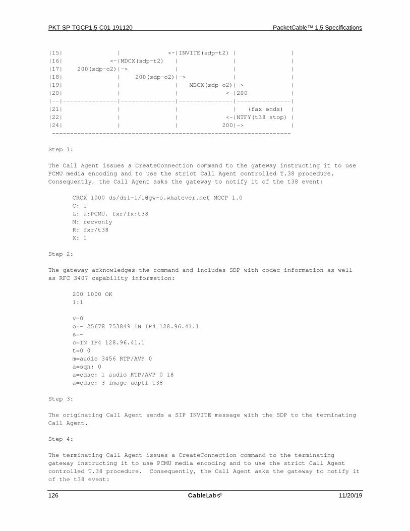
PKT-SP-TGCP1.5-C01-191120 PacketCable™ 1.5 Specifications
126 CableLabs 11/20/19
|15| | <-|INVITE(sdp-t2) | | |16| <-|MDCX(sdp-t2) | | | |17| 200(sdp-o2)|-> | | | |18| | 200(sdp-o2)|-> | | |19| | | MDCX(sdp-o2)|-> | |20| | | <-|200 | |--|---------------|---------------|---------------|---------------| |21| | | | (fax ends) | |22| | | <-|NTFY(t38 stop) | |24| | | 200|-> | ------------------------------------------------------------------ Step 1: The Call Agent issues a CreateConnection command to the gateway instructing it to use PCMU media encoding and to use the strict Call Agent controlled T.38 procedure. Consequently, the Call Agent asks the gateway to notify it of the t38 event: CRCX 1000 ds/ds1-1/[email protected] MGCP 1.0 C: 1 L: a:PCMU, fxr/fx:t38 M: recvonly R: fxr/t38 X: 1 Step 2: The gateway acknowledges the command and includes SDP with codec information as well as RFC 3407 capability information: 200 1000 OK I:1 v=0 o=- 25678 753849 IN IP4 128.96.41.1 s=- c=IN IP4 128.96.41.1 t=0 0 m=audio 3456 RTP/AVP 0 a=sqn: 0 a=cdsc: 1 audio RTP/AVP 0 18 a=cdsc: 3 image udptl t38 Step 3: The originating Call Agent sends a SIP INVITE message with the SDP to the terminating Call Agent. Step 4: The terminating Call Agent issues a CreateConnection command to the terminating gateway instructing it to use PCMU media encoding and to use the strict Call Agent controlled T.38 procedure. Consequently, the Call Agent asks the gateway to notify it of the t38 event:

PSTN Gateway Call Signaling Protocol Specification PKT-SP-TGCP1.5-C01-191120
11/20/19 CableLabs 127
CRCX 2000 ds/ds1-1/[email protected] MGCP 1.0 C: 2 L: a:PCMU, fxr/fx:t38 M: sendrecv R: fxr/t38 X: 20 v=0 o=- 25678 753849 IN IP4 128.96.41.1 s=- c=IN IP4 128.96.41.1 t=0 0 m=audio 3456 RTP/AVP 0 a=sqn: 0 a=cdsc: 1 audio RTP/AVP 0 18 a=cdsc: 3 image udptl t38 Step 5: The terminating gateway supports T.38, and the RemoteConnectionDescriptor included indicates that the other side supports T.38 as well, so the strict T.38 Call Agent controlled procedure requested can be used. The terminating gateway sends back a success response with its SDP which also includes capability information: 200 2000 OK I:2 v=0 o=- 25678 753849 IN IP4 128.96.41.2 s=- c=IN IP4 128.96.41.2 t=0 0 m=audio 1296 RTP/AVP 0 a=sqn: 0 a=cdsc: 1 audio RTP/AVP 0 18 a=cdsc: 3 image udptl t38 Step 6: The terminating Call Agent sends back a SIP 200 OK response to the originating Call Agent, which in turn sends a SIP ACK (not shown). Step 7: The originating Call Agent in turns sends a ModifyConnection command to the originating gateway: MDCX 1001 ds/ds1-1/[email protected] MGCP 1.0 C: 1 I: 1 M: sendrecv v=0
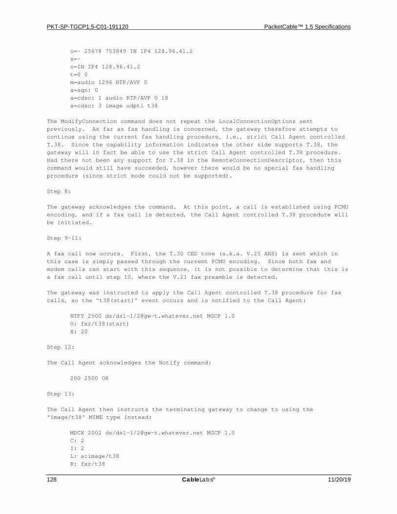
PKT-SP-TGCP1.5-C01-191120 PacketCable™ 1.5 Specifications
128 CableLabs 11/20/19
o=- 25678 753849 IN IP4 128.96.41.2 s=- c=IN IP4 128.96.41.2 t=0 0 m=audio 1296 RTP/AVP 0 a=sqn: 0 a=cdsc: 1 audio RTP/AVP 0 18 a=cdsc: 3 image udptl t38 The ModifyConnection command does not repeat the LocalConnectionOptions sent previously. As far as fax handling is concerned, the gateway therefore attempts to continue using the current fax handling procedure, i.e., strict Call Agent controlled T.38. Since the capability information indicates the other side supports T.38, the gateway will in fact be able to use the strict Call Agent controlled T.38 procedure. Had there not been any support for T.38 in the RemoteConnectionDescriptor, then this command would still have succeeded, however there would be no special fax handling procedure (since strict mode could not be supported). Step 8: The gateway acknowledges the command. At this point, a call is established using PCMU encoding, and if a fax call is detected, the Call Agent controlled T.38 procedure will be initiated. Step 9-11: A fax call now occurs. First, the T.30 CED tone (a.k.a. V.25 ANS) is sent which in this case is simply passed through the current PCMU encoding. Since both fax and modem calls can start with this sequence, it is not possible to determine that this is a fax call until step 10, where the V.21 fax preamble is detected. The gateway was instructed to apply the Call Agent controlled T.38 procedure for fax calls, so the "t38(start)" event occurs and is notified to the Call Agent: NTFY 2500 ds/ds1-1/[email protected] MGCP 1.0 O: fxr/t38(start) X: 20 Step 12: The Call Agent acknowledges the Notify command: 200 2500 OK Step 13: The Call Agent then instructs the terminating gateway to change to using the "image/t38" MIME type instead: MDCX 2002 ds/ds1-1/[email protected] MGCP 1.0 C: 2 I: 2 L: a:image/t38 R: fxr/t38
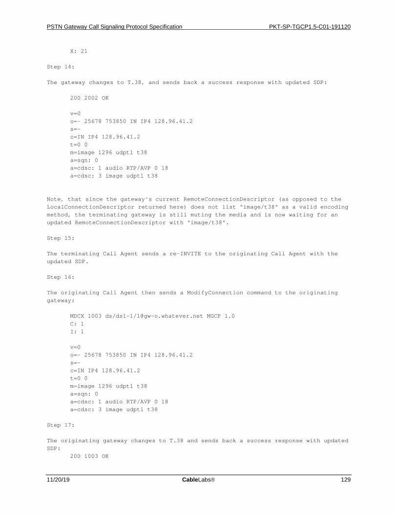
PSTN Gateway Call Signaling Protocol Specification PKT-SP-TGCP1.5-C01-191120
11/20/19 CableLabs 129
X: 21 Step 14: The gateway changes to T.38, and sends back a success response with updated SDP: 200 2002 OK v=0 o=- 25678 753850 IN IP4 128.96.41.2 s=- c=IN IP4 128.96.41.2 t=0 0 m=image 1296 udptl t38 a=sqn: 0 a=cdsc: 1 audio RTP/AVP 0 18 a=cdsc: 3 image udptl t38 Note, that since the gateway's current RemoteConnectionDescriptor (as opposed to the LocalConnectionDescriptor returned here) does not list "image/t38" as a valid encoding method, the terminating gateway is still muting the media and is now waiting for an updated RemoteConnectionDescriptor with "image/t38". Step 15: The terminating Call Agent sends a re-INVITE to the originating Call Agent with the updated SDP. Step 16: The originating Call Agent then sends a ModifyConnection command to the originating gateway: MDCX 1003 ds/ds1-1/[email protected] MGCP 1.0 C: 1 I: 1 v=0 o=- 25678 753850 IN IP4 128.96.41.2 s=- c=IN IP4 128.96.41.2 t=0 0 m=image 1296 udptl t38 a=sqn: 0 a=cdsc: 1 audio RTP/AVP 0 18 a=cdsc: 3 image udptl t38 Step 17: The originating gateway changes to T.38 and sends back a success response with updated SDP: 200 1003 OK
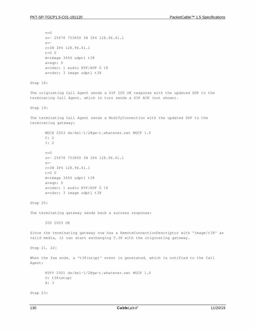
PKT-SP-TGCP1.5-C01-191120 PacketCable™ 1.5 Specifications
130 CableLabs 11/20/19
v=0 o=- 25678 753850 IN IP4 128.96.41.1 s=- c=IN IP4 128.96.41.1 t=0 0 m=image 3456 udptl t38 a=sqn: 0 a=cdsc: 1 audio RTP/AVP 0 18 a=cdsc: 3 image udptl t38 Step 18: The originating Call Agent sends a SIP 200 OK response with the updated SDP to the terminating Call Agent, which in turn sends a SIP ACK (not shown). Step 19: The terminating Call Agent sends a ModifyConnection with the updated SDP to the terminating gateway: MDCX 2003 ds/ds1-1/[email protected] MGCP 1.0 C: 2 I: 2 v=0 o=- 25678 753850 IN IP4 128.96.41.1 s=- c=IN IP4 128.96.41.1 t=0 0 m=image 3456 udptl t38 a=sqn: 0 a=cdsc: 1 audio RTP/AVP 0 18 a=cdsc: 3 image udptl t38 Step 20: The terminating gateway sends back a success response: 200 2003 OK Since the terminating gateway now has a RemoteConnectionDescriptor with "image/t38" as valid media, it can start exchanging T.38 with the originating gateway. Step 21, 22: When the fax ends, a "t38(stop)" event is generated, which is notified to the Call Agent: NTFY 2501 ds/ds1-1/[email protected] MGCP 1.0 O: t38(stop) X: 3 Step 23:
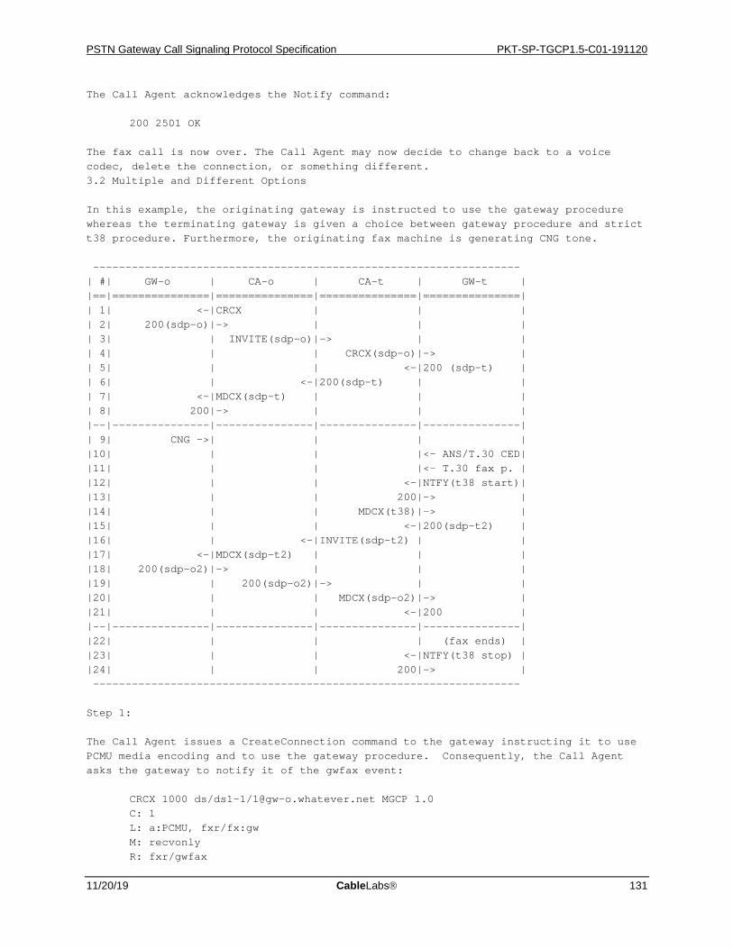
PSTN Gateway Call Signaling Protocol Specification PKT-SP-TGCP1.5-C01-191120
11/20/19 CableLabs 131
The Call Agent acknowledges the Notify command: 200 2501 OK The fax call is now over. The Call Agent may now decide to change back to a voice codec, delete the connection, or something different. 3.2 Multiple and Different Options In this example, the originating gateway is instructed to use the gateway procedure whereas the terminating gateway is given a choice between gateway procedure and strict t38 procedure. Furthermore, the originating fax machine is generating CNG tone. ------------------------------------------------------------------ | #| GW-o | CA-o | CA-t | GW-t | |==|===============|===============|===============|===============| | 1| <-|CRCX | | | | 2| 200(sdp-o)|-> | | | | 3| | INVITE(sdp-o)|-> | | | 4| | | CRCX(sdp-o)|-> | | 5| | | <-|200 (sdp-t) | | 6| | <-|200(sdp-t) | | | 7| <-|MDCX(sdp-t) | | | | 8| 200|-> | | | |--|---------------|---------------|---------------|---------------| | 9| CNG ->| | | | |10| | | |<- ANS/T.30 CED| |11| | | |<- T.30 fax p. | |12| | | <-|NTFY(t38 start)| |13| | | 200|-> | |14| | | MDCX(t38)|-> | |15| | | <-|200(sdp-t2) | |16| | <-|INVITE(sdp-t2) | | |17| <-|MDCX(sdp-t2) | | | |18| 200(sdp-o2)|-> | | | |19| | 200(sdp-o2)|-> | | |20| | | MDCX(sdp-o2)|-> | |21| | | <-|200 | |--|---------------|---------------|---------------|---------------| |22| | | | (fax ends) | |23| | | <-|NTFY(t38 stop) | |24| | | 200|-> | ------------------------------------------------------------------ Step 1: The Call Agent issues a CreateConnection command to the gateway instructing it to use PCMU media encoding and to use the gateway procedure. Consequently, the Call Agent asks the gateway to notify it of the gwfax event: CRCX 1000 ds/ds1-1/[email protected] MGCP 1.0 C: 1 L: a:PCMU, fxr/fx:gw M: recvonly R: fxr/gwfax

PKT-SP-TGCP1.5-C01-191120 PacketCable™ 1.5 Specifications
132 CableLabs 11/20/19
X: 1 Step 2: The gateway acknowledges the command and includes SDP with codec information as well as capability information: 200 1000 OK I:1 v=0 o=- 25678 753849 IN IP4 128.96.41.1 s=- c=IN IP4 128.96.41.1 t=0 0 m=audio 3456 RTP/AVP 0 a=sqn: 0 a=cdsc: 1 audio RTP/AVP 0 18 a=cdsc: 3 image udptl t38 a=X-FaxScheme123 We assume the gateway supports some other fax scheme and it indicates this by including an attribute "FaxScheme123" Step 3: The originating Call Agent sends a SIP INVITE message with the SDP to the terminating Call Agent. Step 4: The terminating Call Agent issues a CreateConnection command to the terminating gateway instructing it to use PCMU media encoding and to use either the gateway procedure or strict Call Agent controlled T.38 procedure. Consequently, the Call Agent asks the gateway to notify it of both the gwfax and t38 events: CRCX 2000 ds/ds1-1/[email protected] MGCP 1.0 C: 2 L: a:PCMU, fxr/fx:gw;t38 M: sendrecv R: fxr/t38, fxr/gwfax X: 20 v=0 o=- 25678 753849 IN IP4 128.96.41.1 s=- c=IN IP4 128.96.41.1 t=0 0 m=audio 3456 RTP/AVP 0 a=sqn: 0 a=cdsc: 1 audio RTP/AVP 0 18 a=cdsc: 3 image udptl t38 a=X-FaxScheme123
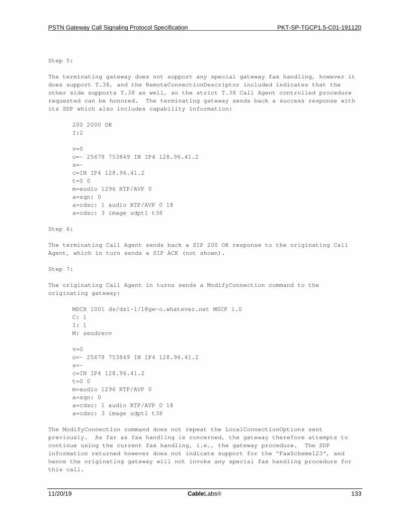
PSTN Gateway Call Signaling Protocol Specification PKT-SP-TGCP1.5-C01-191120
11/20/19 CableLabs 133
Step 5: The terminating gateway does not support any special gateway fax handling, however it does support T.38, and the RemoteConnectionDescriptor included indicates that the other side supports T.38 as well, so the strict T.38 Call Agent controlled procedure requested can be honored. The terminating gateway sends back a success response with its SDP which also includes capability information: 200 2000 OK I:2 v=0 o=- 25678 753849 IN IP4 128.96.41.2 s=- c=IN IP4 128.96.41.2 t=0 0 m=audio 1296 RTP/AVP 0 a=sqn: 0 a=cdsc: 1 audio RTP/AVP 0 18 a=cdsc: 3 image udptl t38 Step 6: The terminating Call Agent sends back a SIP 200 OK response to the originating Call Agent, which in turn sends a SIP ACK (not shown). Step 7: The originating Call Agent in turns sends a ModifyConnection command to the originating gateway: MDCX 1001 ds/ds1-1/[email protected] MGCP 1.0 C: 1 I: 1 M: sendrecv v=0 o=- 25678 753849 IN IP4 128.96.41.2 s=- c=IN IP4 128.96.41.2 t=0 0 m=audio 1296 RTP/AVP 0 a=sqn: 0 a=cdsc: 1 audio RTP/AVP 0 18 a=cdsc: 3 image udptl t38 The ModifyConnection command does not repeat the LocalConnectionOptions sent previously. As far as fax handling is concerned, the gateway therefore attempts to continue using the current fax handling, i.e., the gateway procedure. The SDP information returned however does not indicate support for the "FaxScheme123", and hence the originating gateway will not invoke any special fax handling procedure for this call.
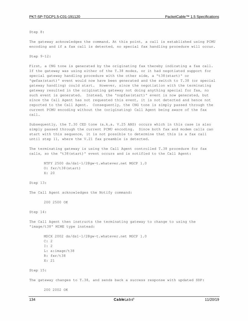
PKT-SP-TGCP1.5-C01-191120 PacketCable™ 1.5 Specifications
134 CableLabs 11/20/19
Step 8: The gateway acknowledges the command. At this point, a call is established using PCMU encoding and if a fax call is detected, no special fax handling procedure will occur. Step 9-12: First, a CNG tone is generated by the originating fax thereby indicating a fax call. If the gateway was using either of the T.38 modes, or it had negotiated support for special gateway handling procedure with the other side, a "t38(start)" or "gwfax(start)" event would now have been generated and the switch to T.38 (or special gateway handling) could start. However, since the negotiation with the terminating gateway resulted in the originating gateway not doing anything special for fax, no such event is generated. Instead, the "nopfax(start)" event is now generated, but since the Call Agent has not requested this event, it is not detected and hence not reported to the Call Agent. Consequently, the CNG tone is simply passed through the current PCMU encoding without the (originating) Call Agent being aware of the fax call. Subsequently, the T.30 CED tone (a.k.a. V.25 ANS) occurs which in this case is also simply passed through the current PCMU encoding. Since both fax and modem calls can start with this sequence, it is not possible to determine that this is a fax call until step 11, where the V.21 fax preamble is detected. The terminating gateway is using the Call Agent controlled T.38 procedure for fax calls, so the "t38(start)" event occurs and is notified to the Call Agent: NTFY 2500 ds/ds1-1/[email protected] MGCP 1.0 O: fxr/t38(start) X: 20 Step 13: The Call Agent acknowledges the Notify command: 200 2500 OK Step 14: The Call Agent then instructs the terminating gateway to change to using the "image/t38" MIME type instead: MDCX 2002 ds/ds1-1/[email protected] MGCP 1.0 C: 2 I: 2 L: a:image/t38 R: fxr/t38 X: 21 Step 15: The gateway changes to T.38, and sends back a success response with updated SDP: 200 2002 OK
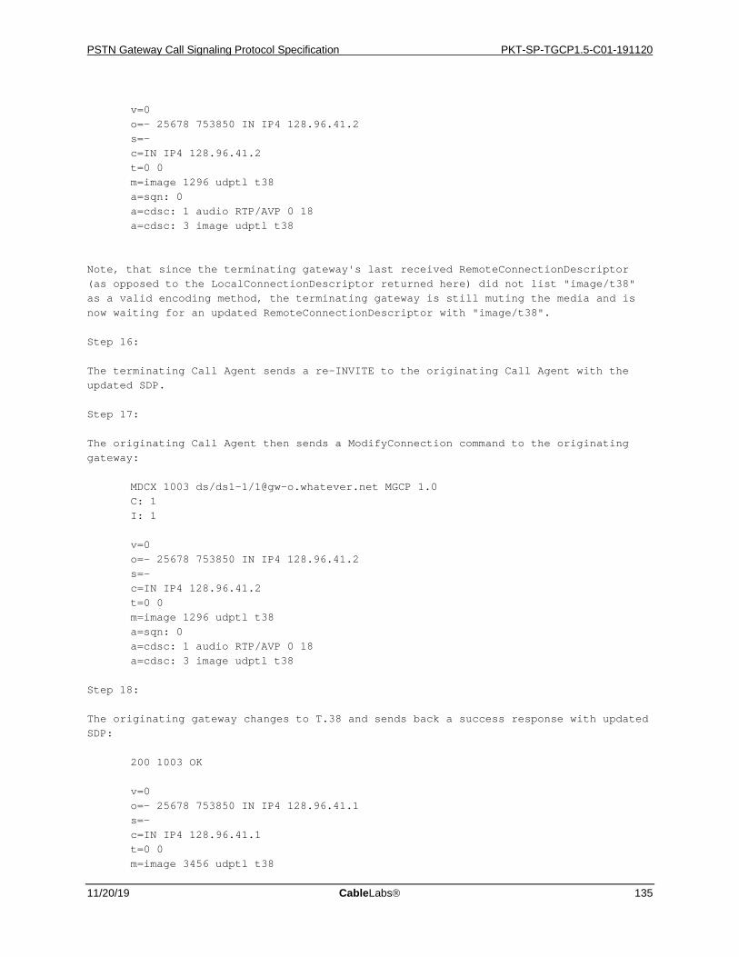
PSTN Gateway Call Signaling Protocol Specification PKT-SP-TGCP1.5-C01-191120
11/20/19 CableLabs 135
v=0 o=- 25678 753850 IN IP4 128.96.41.2 s=- c=IN IP4 128.96.41.2 t=0 0 m=image 1296 udptl t38 a=sqn: 0 a=cdsc: 1 audio RTP/AVP 0 18 a=cdsc: 3 image udptl t38 Note, that since the terminating gateway's last received RemoteConnectionDescriptor (as opposed to the LocalConnectionDescriptor returned here) did not list "image/t38" as a valid encoding method, the terminating gateway is still muting the media and is now waiting for an updated RemoteConnectionDescriptor with "image/t38". Step 16: The terminating Call Agent sends a re-INVITE to the originating Call Agent with the updated SDP. Step 17: The originating Call Agent then sends a ModifyConnection command to the originating gateway: MDCX 1003 ds/ds1-1/[email protected] MGCP 1.0 C: 1 I: 1 v=0 o=- 25678 753850 IN IP4 128.96.41.2 s=- c=IN IP4 128.96.41.2 t=0 0 m=image 1296 udptl t38 a=sqn: 0 a=cdsc: 1 audio RTP/AVP 0 18 a=cdsc: 3 image udptl t38 Step 18: The originating gateway changes to T.38 and sends back a success response with updated SDP: 200 1003 OK v=0 o=- 25678 753850 IN IP4 128.96.41.1 s=- c=IN IP4 128.96.41.1 t=0 0 m=image 3456 udptl t38

PKT-SP-TGCP1.5-C01-191120 PacketCable™ 1.5 Specifications
136 CableLabs 11/20/19
a=sqn: 0 a=cdsc: 1 audio RTP/AVP 0 18 a=cdsc: 3 image udptl t38 Step 19: The originating Call Agent sends a SIP 200 OK response with the updated SDP to the terminating Call Agent, which in turn sends a SIP ACK (not shown). Step 20: The terminating Call Agent sends a ModifyConnection with the updated SDP to the terminating gateway: MDCX 2003 ds/ds1-1/[email protected] MGCP 1.0 C: 2 I: 2 v=0 o=- 25678 753850 IN IP4 128.96.41.1 s=- c=IN IP4 128.96.41.1 t=0 0 m=image 3456 udptl t38 a=sqn: 0 a=cdsc: 1 audio RTP/AVP 0 18 a=cdsc: 3 image udptl t38 Step 21: The terminating gateway sends back a success response: 200 2003 OK Since the terminating gateway now has a RemoteConnectionDescriptor with "image/t38" as valid media, it can start exchanging T.38 with the originating gateway. Step 22, 23: When the fax ends, a "t38(stop)" event is generated, which is notified to the Call Agent: NTFY 2501 ds/ds1-1/[email protected] MGCP 1.0 O: t38(stop) X: 3 Step 24: The Call Agent acknowledges the Notify command: 200 2501 OK The fax call is now over. The Call Agent may now decide to change back to a voice codec, delete the connection, or something different.
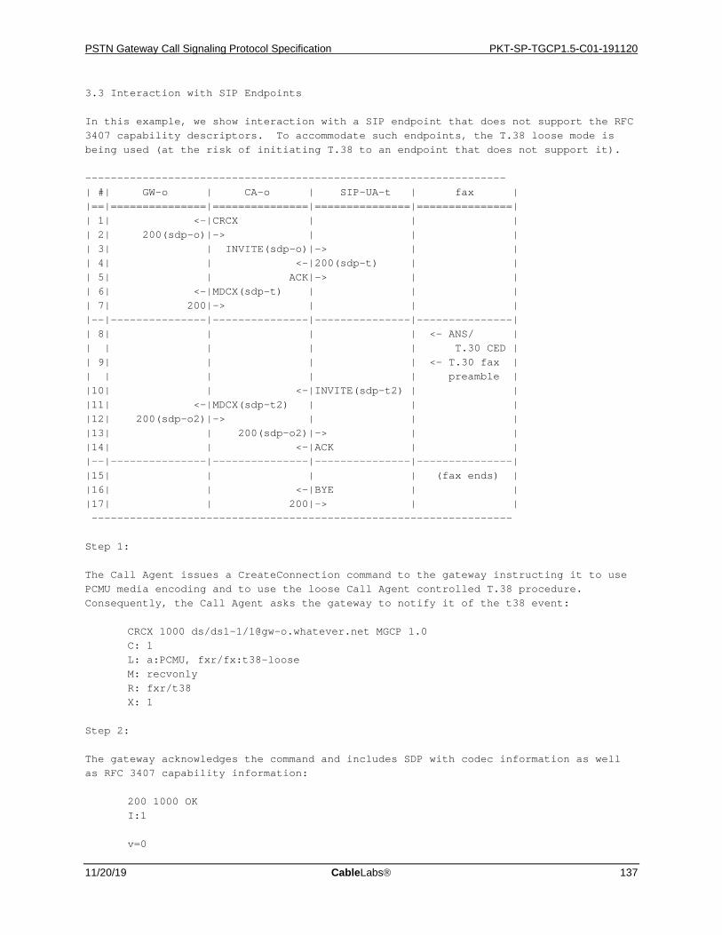
PSTN Gateway Call Signaling Protocol Specification PKT-SP-TGCP1.5-C01-191120
11/20/19 CableLabs 137
3.3 Interaction with SIP Endpoints In this example, we show interaction with a SIP endpoint that does not support the RFC 3407 capability descriptors. To accommodate such endpoints, the T.38 loose mode is being used (at the risk of initiating T.38 to an endpoint that does not support it). ------------------------------------------------------------------ | #| GW-o | CA-o | SIP-UA-t | fax | |==|===============|===============|===============|===============| | 1| <-|CRCX | | | | 2| 200(sdp-o)|-> | | | | 3| | INVITE(sdp-o)|-> | | | 4| | <-|200(sdp-t) | | | 5| | ACK|-> | | | 6| <-|MDCX(sdp-t) | | | | 7| 200|-> | | | |--|---------------|---------------|---------------|---------------| | 8| | | | <- ANS/ | | | | | | T.30 CED | | 9| | | | <- T.30 fax | | | | | | preamble | |10| | <-|INVITE(sdp-t2) | | |11| <-|MDCX(sdp-t2) | | | |12| 200(sdp-o2)|-> | | | |13| | 200(sdp-o2)|-> | | |14| | <-|ACK | | |--|---------------|---------------|---------------|---------------| |15| | | | (fax ends) | |16| | <-|BYE | | |17| | 200|-> | | ------------------------------------------------------------------ Step 1: The Call Agent issues a CreateConnection command to the gateway instructing it to use PCMU media encoding and to use the loose Call Agent controlled T.38 procedure. Consequently, the Call Agent asks the gateway to notify it of the t38 event: CRCX 1000 ds/ds1-1/[email protected] MGCP 1.0 C: 1 L: a:PCMU, fxr/fx:t38-loose M: recvonly R: fxr/t38 X: 1 Step 2: The gateway acknowledges the command and includes SDP with codec information as well as RFC 3407 capability information: 200 1000 OK I:1 v=0
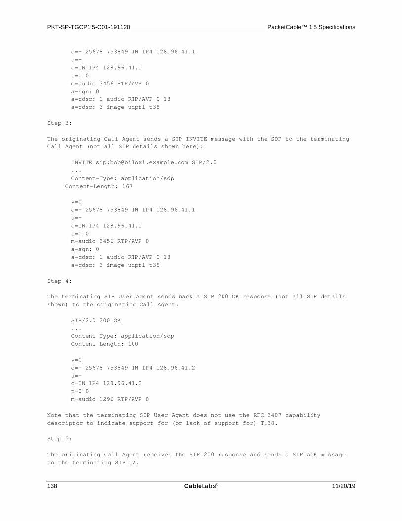
PKT-SP-TGCP1.5-C01-191120 PacketCable™ 1.5 Specifications
138 CableLabs 11/20/19
o=- 25678 753849 IN IP4 128.96.41.1 s=- c=IN IP4 128.96.41.1 t=0 0 m=audio 3456 RTP/AVP 0 a=sqn: 0 a=cdsc: 1 audio RTP/AVP 0 18 a=cdsc: 3 image udptl t38 Step 3: The originating Call Agent sends a SIP INVITE message with the SDP to the terminating Call Agent (not all SIP details shown here): INVITE sip:[email protected] SIP/2.0 ... Content-Type: application/sdp Content-Length: 167 v=0 o=- 25678 753849 IN IP4 128.96.41.1 s=- c=IN IP4 128.96.41.1 t=0 0 m=audio 3456 RTP/AVP 0 a=sqn: 0 a=cdsc: 1 audio RTP/AVP 0 18 a=cdsc: 3 image udptl t38 Step 4: The terminating SIP User Agent sends back a SIP 200 OK response (not all SIP details shown) to the originating Call Agent: SIP/2.0 200 OK ... Content-Type: application/sdp Content-Length: 100 v=0 o=- 25678 753849 IN IP4 128.96.41.2 s=- c=IN IP4 128.96.41.2 t=0 0 m=audio 1296 RTP/AVP 0 Note that the terminating SIP User Agent does not use the RFC 3407 capability descriptor to indicate support for (or lack of support for) T.38. Step 5: The originating Call Agent receives the SIP 200 response and sends a SIP ACK message to the terminating SIP UA.
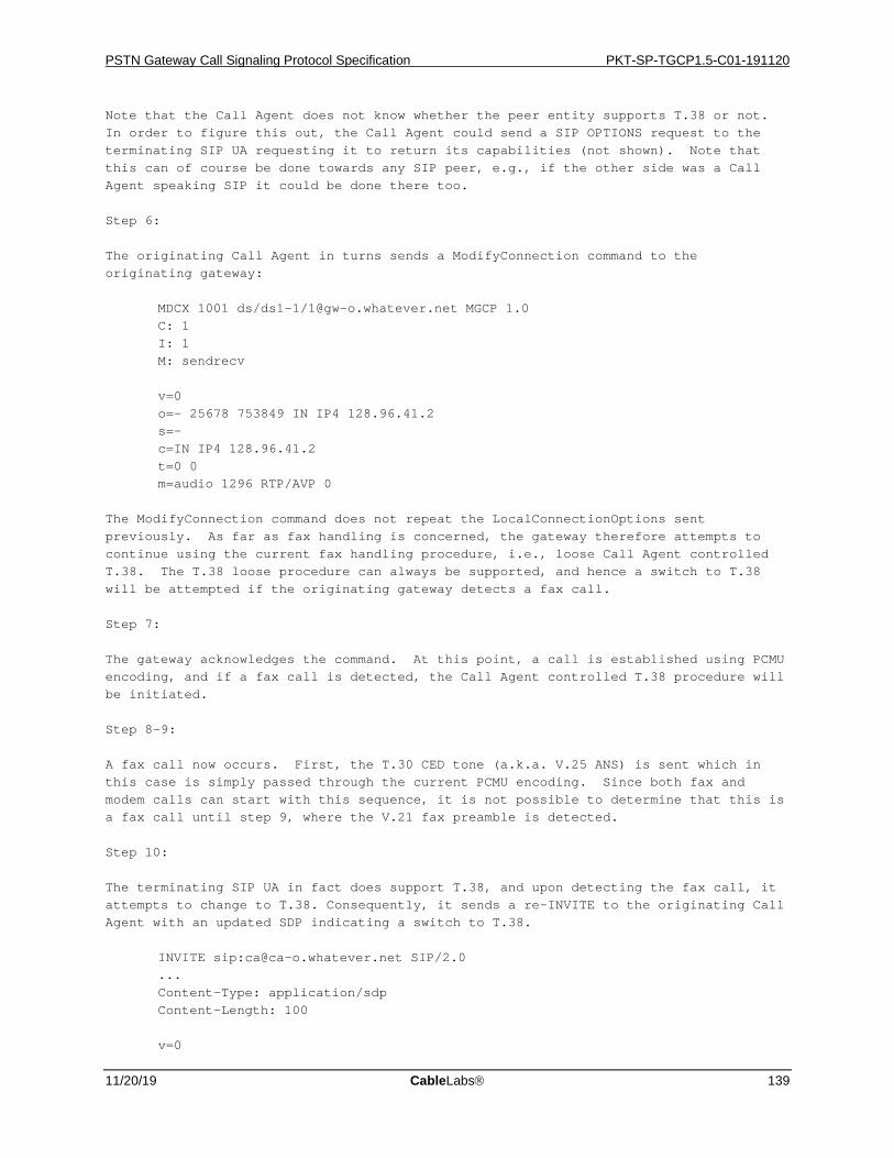
PSTN Gateway Call Signaling Protocol Specification PKT-SP-TGCP1.5-C01-191120
11/20/19 CableLabs 139
Note that the Call Agent does not know whether the peer entity supports T.38 or not. In order to figure this out, the Call Agent could send a SIP OPTIONS request to the terminating SIP UA requesting it to return its capabilities (not shown). Note that this can of course be done towards any SIP peer, e.g., if the other side was a Call Agent speaking SIP it could be done there too. Step 6: The originating Call Agent in turns sends a ModifyConnection command to the originating gateway: MDCX 1001 ds/ds1-1/[email protected] MGCP 1.0 C: 1 I: 1 M: sendrecv v=0 o=- 25678 753849 IN IP4 128.96.41.2 s=- c=IN IP4 128.96.41.2 t=0 0 m=audio 1296 RTP/AVP 0 The ModifyConnection command does not repeat the LocalConnectionOptions sent previously. As far as fax handling is concerned, the gateway therefore attempts to continue using the current fax handling procedure, i.e., loose Call Agent controlled T.38. The T.38 loose procedure can always be supported, and hence a switch to T.38 will be attempted if the originating gateway detects a fax call. Step 7: The gateway acknowledges the command. At this point, a call is established using PCMU encoding, and if a fax call is detected, the Call Agent controlled T.38 procedure will be initiated. Step 8-9: A fax call now occurs. First, the T.30 CED tone (a.k.a. V.25 ANS) is sent which in this case is simply passed through the current PCMU encoding. Since both fax and modem calls can start with this sequence, it is not possible to determine that this is a fax call until step 9, where the V.21 fax preamble is detected. Step 10: The terminating SIP UA in fact does support T.38, and upon detecting the fax call, it attempts to change to T.38. Consequently, it sends a re-INVITE to the originating Call Agent with an updated SDP indicating a switch to T.38. INVITE sip:[email protected] SIP/2.0 ... Content-Type: application/sdp Content-Length: 100 v=0
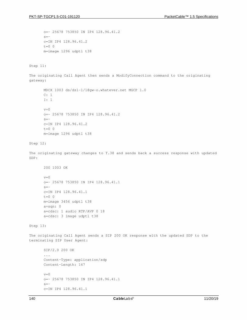
PKT-SP-TGCP1.5-C01-191120 PacketCable™ 1.5 Specifications
140 CableLabs 11/20/19
o=- 25678 753850 IN IP4 128.96.41.2 s=- c=IN IP4 128.96.41.2 t=0 0 m=image 1296 udptl t38 Step 11: The originating Call Agent then sends a ModifyConnection command to the originating gateway: MDCX 1003 ds/ds1-1/[email protected] MGCP 1.0 C: 1 I: 1 v=0 o=- 25678 753850 IN IP4 128.96.41.2 s=- c=IN IP4 128.96.41.2 t=0 0 m=image 1296 udptl t38 Step 12: The originating gateway changes to T.38 and sends back a success response with updated SDP: 200 1003 OK v=0 o=- 25678 753850 IN IP4 128.96.41.1 s=- c=IN IP4 128.96.41.1 t=0 0 m=image 3456 udptl t38 a=sqn: 0 a=cdsc: 1 audio RTP/AVP 0 18 a=cdsc: 3 image udptl t38 Step 13: The originating Call Agent sends a SIP 200 OK response with the updated SDP to the terminating SIP User Agent: SIP/2.0 200 OK ... Content-Type: application/sdp Content-Length: 167 v=0 o=- 25678 753850 IN IP4 128.96.41.1 s=- c=IN IP4 128.96.41.1
PSTN Gateway Call Signaling Protocol Specification PKT-SP-TGCP1.5-C01-191120
11/20/19 CableLabs 141
t=0 0 m=image 3456 udptl t38 a=sqn: 0 a=cdsc: 1 audio RTP/AVP 0 18 a=cdsc: 3 image udptl t38 Step 14: The terminating SIP User Agent receives the SIP 200 and sends a SIP ACK. Since the terminating SIP User Agent now has a RemoteConnectionDescriptor with "image/t38" as valid media, it can start exchanging T.38 with the originating gateway (and vice versa). Step 15-17: When the fax ends, the terminating SIP UA decides to tear down the call and hence sends a SIP BYE message, which the Call Agent responds to with a SIP 200. The Call Agent may now decide to change back to a voice codec, delete the connection, or something different.4. Security Considerations The MGCP fax package itself is not known to introduce any new security concerns. However, implementers should note, that T.38 media is currently transported over UDP (UDPTL) or TCP in clear and without any integrity protection. If for example security services are in place to protect RTP media streams, these will thus not be in effect for the T.38 media stream. If such lack of security is a concern, the fax LocalConnectionOptions allowing T.38 in this package SHOULD NOT be used, i.e., the "off" (or a new secure extension) fax LocalConnectionOption should be used. 5. IANA Considerations The IANA is hereby requested to register the following MGCP package: Package Title Name Version ------------- ---- ------- Fax FXR 0 6. Normative References
[RFC2119] Bradner, S., "Key words for use in RFCs to Indicate Requirement Levels", BCP 14, RFC 2119, March 1997. [RFC3435] F. Andreasen, B. Foster, "Media Gateway Control Protocol (MGCP) Version 1.0", RFC 3435, January 2003. [T38] ITU-T Recommendation T.38, "Procedures for real-time Group 3 facsimile communication over IP networks", 03/2002. [RFC3407] F. Andreasen, "Session Description Protocol (SDP) Simple Capability Declaration", RFC 3407, October 2002.
7. Informative References

PKT-SP-TGCP1.5-C01-191120 PacketCable™ 1.5 Specifications
142 CableLabs 11/20/19
[T30] ITU-T Recommendation T.30, "Procedures for document facsimile transmission in the general switched telephone network", 07/03. [RFC3261] J. Rosenberg, H. Schulzrinne, G. Camarillo, A. Johnston, J. Peterson, R. Sparks, M. Handley, E. Schooler, "SIP: Session Initiation Protocol", RFC 3261, June 2002. [SIPfax] Mule, J., and J. Li, "SIP Support for Real-time Fax: Call Flow Examples and Best Current Practices", work in progress.
8. Acknowledgements Several people have contributed to the development of the MGCP fax package. In particular, the author would like to thank Bill Foster, Paul Jones, Gary Kelly, Rajesh Kumar, Dave Horwitz, Hiroshi Tamura, Rob Thompson and the CableLabs PacketCable NCS focus team for their contributions. 9. Author's Address Flemming Andreasen Cisco Systems 499 Thornall Street, 8th Floor Edison, NJ 08837 Email: [email protected]
PSTN Gateway Call Signaling Protocol Specification PKT-SP-TGCP1.5-C01-191120
11/20/19 CableLabs 143
Intellectual Property Statement The IETF takes no position regarding the validity or scope of any Intellectual Property Rights or other rights that might be claimed to pertain to the implementation or use of the technology described in this document or the extent to which any license under such rights might or might not be available; nor does it represent that it has made any independent effort to identify any such rights. Information on the IETF's procedures with respect to rights in IETF Documents can be found in BCP 78 and BCP 79. Copies of IPR disclosures made to the IETF Secretariat and any assurances of licenses to be made available, or the result of an attempt made to obtain a general license or permission for the use of such proprietary rights by implementers or users of this specification can be obtained from the IETF on-line IPR repository at http://www.ietf.org/ipr. The IETF invites any interested party to bring to its attention any copyrights, patents or patent applications, or other proprietary rights that may cover technology that may be required to implement this standard. Please address the information to the IETF at [email protected]. Disclaimer of Validity This document and the information contained herein are provided on an "AS IS" basis and THE CONTRIBUTOR, THE ORGANIZATION HE/SHE REPRESENTS OR IS SPONSORED BY (IF ANY), THE INTERNET SOCIETY AND THE INTERNET ENGINEERING TASK FORCE DISCLAIM ALL WARRANTIES, EXPRESS OR IMPLIED, INCLUDING BUT NOT LIMITED TO ANY WARRANTY THAT THE USE OF THE INFORMATION HEREIN WILL NOT INFRINGE ANY RIGHTS OR ANY IMPLIED WARRANTIES OF MERCHANTABILITY OR FITNESS FOR A PARTICULAR PURPOSE. Copyright Statement Copyright (C) The Internet Society (2004). This document is subject to the rights, licenses and restrictions contained in BCP 78, and except as set forth therein, the authors retain all their rights. Acknowledgment Funding for the RFC Editor function is currently provided by the Internet Society.
PKT-SP-TGCP1.5-C01-191120 PacketCable™ 1.5 Specifications
144 CableLabs 11/20/19
A.5 VoIP Metrics Package The VoIP Metrics package provides a mechanism to control the collection and reporting of VoIP metrics. The MG MUST support the reporting of VoIP Metric parameters as specified in this package for all Extended Report parameters mandated in [11]. Implementations MUST conform to the TGCP Protocol Version encoding as specified in Section 8.2.1.4.
Internet Engineering Task Force D. Auerbach Cisco Systems D. Hancock CableLabs B. Hare Arris R. Kumar Cisco Systems
Internet Draft Document:.txt October 1, 2004 Category: Informational Media Gateway Control Protocol VoIP RTCP-XR Metrics Package Status of this Memo By submitting this Internet-Draft, we certify that any applicable patent or other IPR claims of which we am aware have been disclosed, and any of which we become aware will be disclosed, in accordance with RFC 3668. Internet-Drafts are working documents of the Internet Engineering Task Force (IETF), its areas, and its working groups. Note that other groups may also distribute working documents as Internet-Drafts. Internet-Drafts are draft documents valid for a maximum of six months and may be updated, replaced, or obsoleted by other documents at any time. It is inappropriate to use Internet-Drafts as reference material or to cite them other than as "work in progress." The list of current Internet-Drafts can be accessed at http://www.ietf.org/ietf/1id-abstracts.txt. The list of Internet-Draft Shadow Directories can be accessed at http://www.ietf.org/shadow.html. This Internet-Draft will expire on March 1, 2005. Abstract This document defines a Media Gateway Control Protocol (MGCP) package to control the collection of metrics supported by RTCP Extended Report as specified in RFC 3611. The package allows for the call agent to enable or disable the collection of these metrics. It also allows the call agent to control whether or not the gateway will respond to remote requests for metric collection from a peer gateway.
PSTN Gateway Call Signaling Protocol Specification PKT-SP-TGCP1.5-C01-191120
11/20/19 CableLabs 145
In addition to the parameters in the RTCP-XR VoIP metrics block, this document includes the inter-arrival jitter as defined in RFC 3550. The purpose of this inclusion is the alignment of MGCP-based VoIP metrics reporting with SIP. Note that the MGCP ConnectionParameters structure [RFC3435] allows the reporting of the local, but not the remote, version of this parameter. Conventions used in this document The key words "MUST", "MUST NOT", "REQUIRED", "SHALL", "SHALL NOT", "SHOULD", "SHOULD NOT", "RECOMMENDED", "MAY", and "OPTIONAL" in this document are to be interpreted as described in BCP 14, RFC 2119 [RFC2119]. Table of Contents 1. Introduction 2. VoIP Metrics Package Definition 2.1 LocalConnectionOptions 2.1.1 Endpoint Procedures 2.1.1.1 Off Procedure 2.1.1.2 On Procedure 2.1.1.3 Negotiate Procedure 2.2 AuditConnection procedures 2.3 New MGCP Extension Parameters 2.3.1 Extension Parameter Values 2.3.2 Extension Parameter Grammar 2.4 VoIP Metrics Negotiation 2.5 Implementation Considerations 2.5.1 Inter-working Considerations 3. Call Flow Examples 3.1 Call agent initiated DLCX 3.2 Gateway initiated DLCX 4. Security Considerations 5. IANA Considerations 6. Normative References 7. Acknowledgments . 1. Introduction This document defines a Media Gateway Control Protocol (MGCP) [RFC3435] package that enables the collection and reporting of metrics that measure the quality of voice traffic on VoIP connections. This capability is based on and utilizes the VoIP Metrics Block of the RTCP Extended Report as specified in RFC 3611 [27]. This package makes a distinction between collecting, responding and reporting. The term "collecting" refers to the process of calculating and accumulating local VoIP metrics data and accumulating remote VoIP metrics data received in RTCP XR packets from the remote device. The term "responding" is the sending of the accumulated local metrics data in RTCP XR packets to the remote connected device as specified in RFC 3611. The term "reporting" refers to the process of reporting the accumulated local and remote VoIP metric data for the connection to the Call Agent in either a DeleteConnection or AuditConnection command sequence.

PKT-SP-TGCP1.5-C01-191120 PacketCable™ 1.5 Specifications
146 CableLabs 11/20/19
The Call Agent can ask a local endpoint to enable (or disable) VoIP metrics reporting for a connection in the CreateConnection or ModifyConnection command. When VoIP metrics reporting is enabled, the local endpoint will use SDP signaling as specified in RFC 3611 to ask the remote endpoint to start transmitting RTCP XR VoIP metrics data for the remote end of the connection. The local endpoint will accumulate a local and remote copy of the VoIP metrics data to be reported to the Call Agent when the connection is deleted, or audited (and the metrics data is requested). An endpoint will collect local VoIP metric data for two separate reasons; when VoIP metrics reporting is enabled by the Call Agent via connection command, or when requested to collect VoIP metrics by the remote endpoint via SDP signaling. The Call Agent can inhibit the collection and responding to remote endpoints by specifically turning off the collection/responding function. The VoIP metrics data that is reported to the Call Agent when the connection is deleted represents the data that was accumulated since the endpoint started collecting originally on the connection, whether collecting was initiated by a Call Agent request or by SDP signaling. This package is designed to provide an accurate measure of voice quality for basic 2-way call connections, where metrics are accumulated over the life of the connection and reported to the Call Agent when the connection is deleted. The package does not make any special provisions for mid-call path reconfiguration events that could affect voice quality. For example, if a ModifyConnection command changes the remote endpoint of a connection, the single metrics report generated when the connection is subsequently deleted would not provide any means to compare the metrics before and after the remote endpoint was changed. Note that this package does not affect the reporting of other MGCP statistics as defined in the base protocols. The VoIP Metrics package definition is provided in Section 2 and in Section 3 we provide two call flow examples showing how to use it. Security considerations are found in Section 4, followed by the IANA considerations and references. 2. VoIP Metrics Package Definition A package is defined for VoIP Metrics. The package defines new localconnectionoptions, and connection parameters as detailed below. Package Name: XRM Package Version: 0 2.1 LocalConnectionOptions This package defines a new LocalConnectionOptions (LCO) parameter to enable and disable VoIP Metrics reporting at the gateway. This is an optional parameter with a default value of "negotiate". The Call Agent supplies this LCO parameter to instruct the endpoint to enable or disable the collection and reporting of RTCP-XR Metrics for the target connection. The new parameter is the metric collection (and) report parameter and is encoded as "mcr". The parameter can have one of the following three values: · off - disable VoIP metrics collecting, reporting and responding (encoded as "off").
PSTN Gateway Call Signaling Protocol Specification PKT-SP-TGCP1.5-C01-191120
11/20/19 CableLabs 147
· on - enable VoIP metrics collecting, reporting and responding (encoded as "on"). · negotiate – allow VoIP metrics collecting and responding if requested but disable VoIP reporting (encoded as "negotiate"). The following example shows how to use this parameter to turn VoIP metrics collection, reporting and responding on: L: xrm/mcr:on In CreateConnection commands, the xrm/mcr LCO value defaults to "negotiate". In ModifyConnection commands, the xrm/mcr LCO value defaults to its current value for the connection. Thus, if LocalConnectionOptions are either omitted or the xrm/mcr LCO is not included in a ModifyConnection command, the previous xrm/mcr LCO value for the connection is retained. Note that this LCO directly controls the reporting of XR metrics to the Call Agent and may control the collection of metrics. The collection of metrics is also dependent on a possible request from a peer gateway as indicated in the RemoteConnectionDescriptor. 2.1.1 Endpoint Procedures This section describes the endpoint procedures for each of the xrm/mcr parameter values. 2.1.1.1 Off Procedure On receiving this value, the endpoint MUST erase any local or remote VoIP metric data previously collected for the connection, and MUST instruct the far-end device to stop sending RTCP XR VoIP Metrics Report Blocks. The endpoint MUST ignore an SDP request for metrics and MUST NOT transmit local metrics to the peer endpoint. The local endpoint MUST NOT report XR metrics upon receiving or initiating a DeleteConnection sequence and MUST NOT report XR metrics when responding to an AuditConnection command. 2.1.1.2 On Procedure On receiving this value, if not already doing so, the endpoint MUST start calculating local VoIP Metrics data for the connection, and MUST instruct the far-end device to start sending VoIP Metrics data for the connection by including an "rtcp-xr" attribute with a value of "voip-metrics" in the SDP. The endpoint MUST report local and remote VoIP metrics in the response to DeleteConnection, in the response to AuditConnection when the metric parameters are audited, and when sending a DeleteConnection command. The endpoint MUST omit the remote metrics from the report if no remote metrics were received from the remote endpoint. 2.1.1.3 Negotiate Procedure On receiving this value, the endpoint does nothing except to set an internal flag to indicate that SDP request for local metrics to be sent to a remote peer endpoint are allowed. The local does not send this information until it is requested to do so by the remote endpoint.
PKT-SP-TGCP1.5-C01-191120 PacketCable™ 1.5 Specifications
148 CableLabs 11/20/19
2.2 AuditConnection procedures This package defines two new RequestedInfo values to be used with an AuditConnection (AUCX). These allow a call agent to explicitly request that the endpoint return the current values of either the local or remote metrics. The request does not reset the values. When one or both of these request info values are included in an AUCX command, the endpoint MUST return the appropriate metric values if available. The two new request info values are: XRM/LVM Return the local voice metric values. XRM/RVM Return the remote voice metric values. If an endpoint is queried about a parameter it does understand, the endpoint MUST NOT generate an error; instead the parameter MUST be omitted from the audit response. If an endpoint is queried about a parameter it does support, but has no value for, the endpoint MUST NOT generate an error; instead the parameter MUST be included in the audit response with an empty parameter value. 2.3 New MGCP Extension Parameters Two new MGCP parameters are defined to support VoIP metrics reporting; one for reporting local metrics data, and one for reporting remote metrics data. They are returned in the DeleteConnection sequence and may be returned by the AuditConnection response (when the audit is requested). Local metrics are included in the "XRM/LVM" line. Remote metrics are included in the XRM/RVM line. As an example, for a gateway that is recording local metrics and has received remote metrics, a DLCX will result in the following additional lines being returned in the response: XRM/LVM: PLC=1, JBA=2, JBR=7 … XRM/RVM: PLC=0, JBA=0, JBR=3 … For the detailed semantics of these parameters, see the description of the VoIP Metrics Report block in RFC 3611. For example, the meaning of "standard" vs. "enhanced" packet loss concealment must be gleaned from RFC 3611. 2.3.1 Extension Parameter Values Unlike RTCP, parameter fields in MGCP are expressed in a text rather than a fixed binary format. Therefore, it is not necessary to stipulate upper bounds for numeric parameters in MGCP. However, the upper bounds specified in RFC 3611 still apply. Note that upper bounds in RFC 3611 are sometimes dictated by regularity in field size (e.g., increments of 8) rather than by the actual range of parameter values. For example, although a numeric value of 65,535 ms can be expressed as a 16-bit field, a viable RTP connection will never have a round trip delay with this value. Extension Parameter Name
Code Value
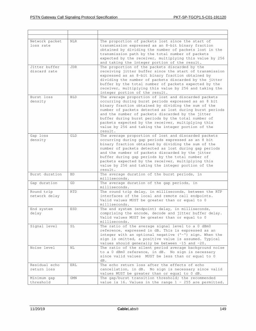
PSTN Gateway Call Signaling Protocol Specification PKT-SP-TGCP1.5-C01-191120
11/20/19 CableLabs 149
Network packet loss rate
NLR The proportion of packets lost since the start of transmission expressed as an 8-bit binary fraction obtained by dividing the number of packets lost in the transmission path by the total number of packets expected by the receiver, multiplying this value by 256 and taking the integer portion of the result.
Jitter buffer discard rate
JDR The proportion of the packets discarded by the receiving jitter buffer since the start of transmission expressed as an 8-bit binary fraction obtained by dividing the number of packets discarded by the jitter buffer by the total number of packets expected by the receiver, multiplying this value by 256 and taking the integer portion of the result.
Burst loss density
BLD The average proportion of lost and discarded packets occurring during burst periods expressed as an 8 bit binary fraction obtained by dividing the sum of the number of packets detected as lost during burst periods and the number of packets discarded by the jitter buffer during burst periods by the total number of packets expected by the receiver, multiplying this value by 256 and taking the integer portion of the result.
Gap loss density
GLD The average proportion of lost and discarded packets occurring during gap periods expressed as an 8 bit binary fraction obtained by dividing the sum of the number of packets detected as lost during gap periods and the number of packets discarded by the jitter buffer during gap periods by the total number of packets expected by the receiver, multiplying this value by 256 and taking the integer portion of the result.
Burst duration BD The average duration of the burst periods, in milliseconds.
Gap duration GD The average duration of the gap periods, in milliseconds.
Round trip network delay
RTD The round trip delay, in milliseconds, between the RTP interfaces of the local and remote call endpoints. Valid values MUST be greater than or equal to 0 milliseconds.
End system delay
ESD The end system (endpoint) delay, in milliseconds, comprising the encode, decode and jitter buffer delay. Valid values MUST be greater than or equal to 0 milliseconds.
Signal level SL The ratio of the average signal level to a 0 dBm0 reference, expressed in dB. This is expressed as an integer with an optional negative ("-") sign. When the sign is omitted, a positive value is assumed. Typical values should generally be between -15 and -20.
Noise level NL The ratio of the silent period average background noise to a 0 dBm0 reference, in dB. No sign is necessary since valid values MUST be less than or equal to 0 dB.
Residual echo return loss
ERL The echo return loss after the effects of echo cancellation, in dB. No sign is necessary since valid values MUST be greater than or equal to 0 dB.
Minimum gap threshold
GMN The gap/burst transition threshold; the recommended value is 16. Values in the range 1 – 255 are permitted.
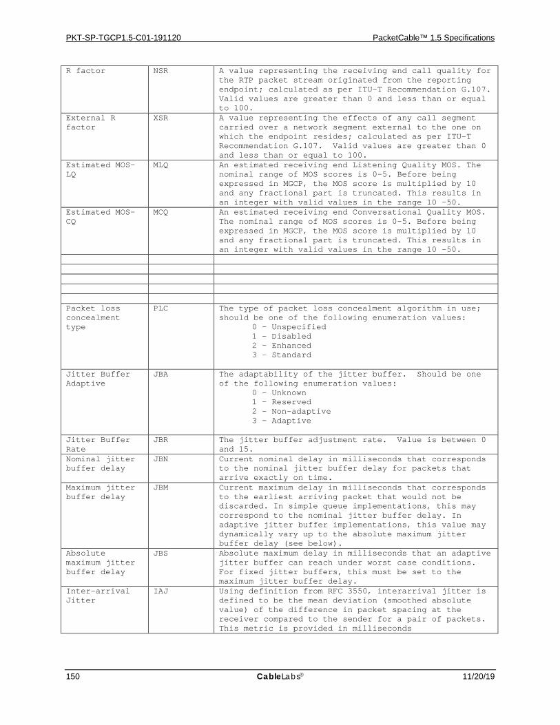
PKT-SP-TGCP1.5-C01-191120 PacketCable™ 1.5 Specifications
150 CableLabs 11/20/19
R factor NSR A value representing the receiving end call quality for the RTP packet stream originated from the reporting endpoint; calculated as per ITU-T Recommendation G.107. Valid values are greater than 0 and less than or equal to 100.
External R factor
XSR A value representing the effects of any call segment carried over a network segment external to the one on which the endpoint resides; calculated as per ITU-T Recommendation G.107. Valid values are greater than 0 and less than or equal to 100.
Estimated MOS-LQ
MLQ An estimated receiving end Listening Quality MOS. The nominal range of MOS scores is 0-5. Before being expressed in MGCP, the MOS score is multiplied by 10 and any fractional part is truncated. This results in an integer with valid values in the range 10 -50.
Estimated MOS-CQ
MCQ An estimated receiving end Conversational Quality MOS. The nominal range of MOS scores is 0-5. Before being expressed in MGCP, the MOS score is multiplied by 10 and any fractional part is truncated. This results in an integer with valid values in the range 10 -50.
Packet loss concealment type
PLC The type of packet loss concealment algorithm in use; should be one of the following enumeration values: 0 – Unspecified 1 – Disabled 2 – Enhanced 3 – Standard
Jitter Buffer Adaptive
JBA The adaptability of the jitter buffer. Should be one of the following enumeration values: 0 – Unknown 1 – Reserved 2 – Non-adaptive 3 – Adaptive
Jitter Buffer Rate
JBR The jitter buffer adjustment rate. Value is between 0 and 15.
Nominal jitter buffer delay
JBN Current nominal delay in milliseconds that corresponds to the nominal jitter buffer delay for packets that arrive exactly on time.
Maximum jitter buffer delay
JBM Current maximum delay in milliseconds that corresponds to the earliest arriving packet that would not be discarded. In simple queue implementations, this may correspond to the nominal jitter buffer delay. In adaptive jitter buffer implementations, this value may dynamically vary up to the absolute maximum jitter buffer delay (see below).
Absolute maximum jitter buffer delay
JBS Absolute maximum delay in milliseconds that an adaptive jitter buffer can reach under worst case conditions. For fixed jitter buffers, this must be set to the maximum jitter buffer delay.
Inter-arrival Jitter
IAJ Using definition from RFC 3550, interarrival jitter is defined to be the mean deviation (smoothed absolute value) of the difference in packet spacing at the receiver compared to the sender for a pair of packets. This metric is provided in milliseconds
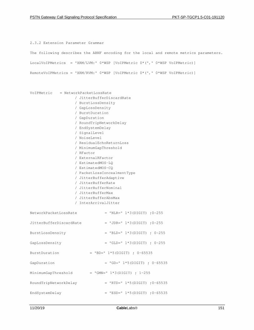
PSTN Gateway Call Signaling Protocol Specification PKT-SP-TGCP1.5-C01-191120
11/20/19 CableLabs 151
2.3.2 Extension Parameter Grammar The following describes the ABNF encoding for the local and remote metrics parameters. LocalVoIPMetrics = "XRM/LVM:" 0*WSP [VoIPMetric 0*("," 0*WSP VoIPMetric)] RemoteVoIPMetrics = "XRM/RVM:" 0*WSP [VoIPMetric 0*("," 0*WSP VoIPMetric)] VoIPMetric = NetworkPacketLossRate / JitterBufferDiscardRate / BurstLossDensity / GapLossDensity / BurstDuration / GapDuration / RoundTripNetworkDelay / EndSystemDelay / SignalLevel / NoiseLevel / ResidualEchoReturnLoss / MinimumGapThreshold / RFactor / ExternalRFactor / EstimatedMOS-LQ / EstimatedMOS-CQ / PacketLossConcealmentType / JitterBufferAdaptive / JitterBufferRate / JitterBufferNominal / JitterBufferMax / JitterBufferAbsMax / InterArrivalJitter NetworkPacketLossRate = "NLR=" 1*3(DIGIT) ;0-255 JitterBufferDiscardRate = "JDR=" 1*3(DIGIT) ;0-255 BurstLossDensity = "BLD=" 1*3(DIGIT) ; 0-255 GapLossDensity = "GLD=" 1*3(DIGIT) ; 0-255 BurstDuration = "BD=" 1*5(DIGIT) ; 0-65535 GapDuration = "GD=" 1*5(DIGIT) ; 0-65535 MinimumGapThreshold = "GMN=" 1*3(DIGIT) ; 1-255 RoundTripNetworkDelay = "RTD=" 1*5(DIGIT) ;0-65535 EndSystemDelay = "ESD=" 1*5(DIGIT) ;0-65535
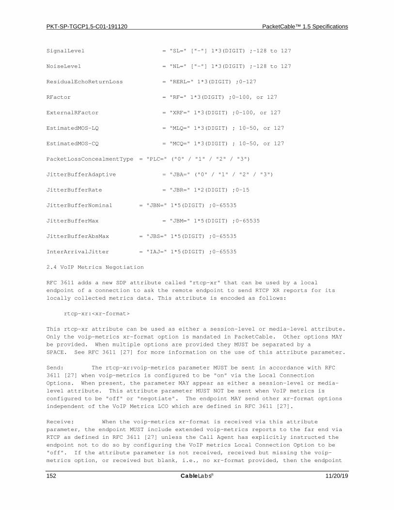
PKT-SP-TGCP1.5-C01-191120 PacketCable™ 1.5 Specifications
152 CableLabs 11/20/19
SignalLevel = "SL=" ["-"] 1*3(DIGIT) ;-128 to 127 NoiseLevel = "NL=" ["-"] 1*3(DIGIT) ;-128 to 127 ResidualEchoReturnLoss = "RERL=" 1*3(DIGIT) ;0-127 RFactor = "RF=" 1*3(DIGIT) ;0-100, or 127 ExternalRFactor = "XRF=" 1*3(DIGIT) ;0-100, or 127 EstimatedMOS-LQ = "MLQ=" 1*3(DIGIT) ; 10-50, or 127 EstimatedMOS-CQ = "MCQ=" 1*3(DIGIT) ; 10-50, or 127 PacketLossConcealmentType = "PLC=" ("0" / "1" / "2" / "3") JitterBufferAdaptive = "JBA=" ("0" / "1" / "2" / "3") JitterBufferRate = "JBR=" 1*2(DIGIT) ;0-15 JitterBufferNominal = "JBN=" 1*5(DIGIT) ;0-65535 JitterBufferMax = "JBM=" 1*5(DIGIT) ;0-65535 JitterBufferAbsMax = "JBS=" 1*5(DIGIT) ;0-65535 InterArrivalJitter = "IAJ=" 1*5(DIGIT) ;0-65535 2.4 VoIP Metrics Negotiation RFC 3611 adds a new SDP attribute called "rtcp-xr" that can be used by a local endpoint of a connection to ask the remote endpoint to send RTCP XR reports for its locally collected metrics data. This attribute is encoded as follows: rtcp-xr:<xr-format> This rtcp-xr attribute can be used as either a session-level or media-level attribute. Only the voip-metrics xr-format option is mandated in PacketCable. Other options MAY be provided. When multiple options are provided they MUST be separated by a SPACE. See RFC 3611 [27] for more information on the use of this attribute parameter. Send: The rtcp-xr:voip-metrics parameter MUST be sent in accordance with RFC 3611 [27] when voip-metrics is configured to be "on" via the Local Connection Options. When present, the parameter MAY appear as either a session-level or media-level attribute. This attribute parameter MUST NOT be sent when VoIP metrics is configured to be "off" or "negotiate". The endpoint MAY send other xr-format options independent of the VoIP Metrics LCO which are defined in RFC 3611 [27]. Receive: When the voip-metrics xr-format is received via this attribute parameter, the endpoint MUST include extended voip-metrics reports to the far end via RTCP as defined in RFC 3611 [27] unless the Call Agent has explicitly instructed the endpoint not to do so by configuring the VoIP metrics Local Connection Option to be "off". If the attribute parameter is not received, received but missing the voip-metrics option, or received but blank, i.e., no xr-format provided, then the endpoint
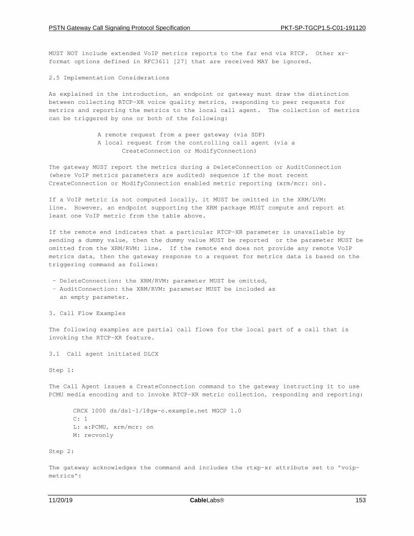
PSTN Gateway Call Signaling Protocol Specification PKT-SP-TGCP1.5-C01-191120
11/20/19 CableLabs 153
MUST NOT include extended VoIP metrics reports to the far end via RTCP. Other xr-format options defined in RFC3611 [27] that are received MAY be ignored. 2.5 Implementation Considerations As explained in the introduction, an endpoint or gateway must draw the distinction between collecting RTCP-XR voice quality metrics, responding to peer requests for metrics and reporting the metrics to the local call agent. The collection of metrics can be triggered by one or both of the following: A remote request from a peer gateway (via SDP) A local request from the controlling call agent (via a CreateConnection or ModifyConnection) The gateway MUST report the metrics during a DeleteConnection or AuditConnection (where VoIP metrics parameters are audited) sequence if the most recent CreateConnection or ModifyConnection enabled metric reporting (xrm/mcr: on). If a VoIP metric is not computed locally, it MUST be omitted in the XRM/LVM: line. However, an endpoint supporting the XRM package MUST compute and report at least one VoIP metric from the table above. If the remote end indicates that a particular RTCP-XR parameter is unavailable by sending a dummy value, then the dummy value MUST be reported or the parameter MUST be omitted from the XRM/RVM: line. If the remote end does not provide any remote VoIP metrics data, then the gateway response to a request for metrics data is based on the triggering command as follows: - DeleteConnection: the XRM/RVM: parameter MUST be omitted, - AuditConnection: the XRM/RVM: parameter MUST be included as an empty parameter. 3. Call Flow Examples The following examples are partial call flows for the local part of a call that is invoking the RTCP-XR feature. 3.1 Call agent initiated DLCX Step 1: The Call Agent issues a CreateConnection command to the gateway instructing it to use PCMU media encoding and to invoke RTCP-XR metric collection, responding and reporting: CRCX 1000 ds/ds1-1/[email protected] MGCP 1.0 C: 1 L: a:PCMU, xrm/mcr: on M: recvonly Step 2: The gateway acknowledges the command and includes the rtxp-xr attribute set to "voip-metrics":
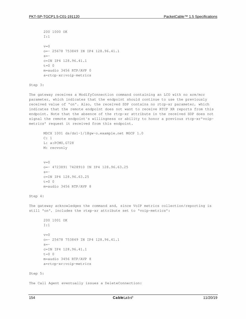
PKT-SP-TGCP1.5-C01-191120 PacketCable™ 1.5 Specifications
154 CableLabs 11/20/19
200 1000 OK I:1 v=0 o=- 25678 753849 IN IP4 128.96.41.1 s=- c=IN IP4 128.96.41.1 t=0 0 m=audio 3456 RTP/AVP 0 a=rtcp-xr:voip-metrics Step 3: The gateway receives a ModifyConnection command containing an LCO with no xrm/mcr parameter, which indicates that the endpoint should continue to use the previously received value of "on". Also, the received SDP contains no rtcp-xr parameter, which indicates that the remote endpoint does not want to receive RTCP XR reports from this endpoint. Note that the absence of the rtcp-xr attribute in the received SDP does not signal the remote endpoint's willingness or ability to honor a previous rtcp-xr"voip-metrics" request it received from this endpoint. MDCX 1001 ds/ds1-1/[email protected] MGCP 1.0 C: 1 L: a:PCMU,G728 M: recvonly v=0 o=- 4723891 7428910 IN IP4 128.96.63.25 s=- c=IN IP4 128.96.63.25 t=0 0 m=audio 3456 RTP/AVP 8 Step 4: The gateway acknowledges the command and, since VoIP metrics collection/reporting is still "on", includes the rtxp-xr attribute set to "voip-metrics": 200 1001 OK I:1 v=0 o=- 25678 753849 IN IP4 128.96.41.1 s=- c=IN IP4 128.96.41.1 t=0 0 m=audio 3456 RTP/AVP 8 a=rtcp-xr:voip-metrics Step 5: The Call Agent eventually issues a DeleteConnection:

PSTN Gateway Call Signaling Protocol Specification PKT-SP-TGCP1.5-C01-191120
11/20/19 CableLabs 155
DLCX 1100 ds/ds1-1/[email protected] MGCP 1.0 C: 1 I: 1 Step 6: The gateway acknowledges the command and returns the standard MGCP connection parameters along with the RTCP-XR parameters (note that new-lines shown here are for document formatting reasons only): 250 1100 OK P: PS=1000, OS=60000, PR=800, OR=50000, PL=10, JI=27, LA=48, XRM/LVM: NLR=128, JDR=40, BLD=33, GLD=10, BD=55, GD=45, RTD=1000, ESD=1000, SL=-10, NL=2, RERL=23, GMN=80, RF=19, XRF=19, MLQ=19, MCQ=22, PLC=1, JBA=2, JBR=8, JBN=40, JBM=80, JBS=120, IAJ=10 XRM/RVM: NLR=128, JDR=40, BLD=33, GLD=10, BD=55, GD=45, RTD=1000, ESD=1000, SL=-10, NL=2, RERL=23, GMN=80, RF=19, XRF=19, MLQ=19, MCQ=22, PLC=1, JBA=0, JBR=8, JBN=30, JBM=60, JBS=100, IAJ=15 3.2 Gateway initiated DLCX Step 1: The Call Agent issues a CreateConnection command to the gateway instructing it to use PCMU media encoding and to invoke RTCP-XR metric collection and reporting: CRCX 1000 ds/ds1-1/[email protected] MGCP 1.0 C: 1 L: a:PCMU, xrm/mcr: on M: recvonly Step 2: The gateway acknowledges the command and includes the rtxp-xr attribute set to "voip-metrics": 200 1000 OK I:1 v=0 o=- 25678 753849 IN IP4 128.96.41.1 s=- c=IN IP4 128.96.41.1 t=0 0 m=audio 3456 RTP/AVP 0 a=rtcp-xr:voip-metrics Step 3: The Gateway issues a DeleteConnection command including the connection parameters and the RTCP metrics: DLCX 1100 ds/ds1-1/[email protected] MGCP 1.0
PKT-SP-TGCP1.5-C01-191120 PacketCable™ 1.5 Specifications
156 CableLabs 11/20/19
C: 1 I: 1 E: 900 – Hardware error P: PS=1000, OS=60000, PR=800, OR=50000, PL=10, JI=27, LA=48, XRM/LVM: NLR=128, JDR=40, BLD=33, GLD=10, BD=55, GD=45, RTD=1000, ESD=1000, SL=-10, NL=2, RERL=23, GMN=80, RF=19, XRF=19, MLQ=19, MCQ=22, PLC=1, JBA=2, JBR=8, JBN=40, JBM=80, JBS=120 XRM/RVM: NLR=128, JDR=40, BLD=33, GLD=10, BD=55, GD=45, RTD=1000, ESD=1000, SL=-10, NL=2, RERL=23, GMN=80, RF=19, XRF=19, MLQ=19, MCQ=22, PLC=1, JBA=0, JBR=8, JBN=30, JBM=60, JBS=100 Note that the IAJ parameter is not included in the XRM/LVM or the XRM/RVM lines. This is just an example of allowed parameter omission. This example could have very well been constructed with the IAJ parameter. Step 4: The Call Agent acknowledges the command: 200 1100 OK 4. Security Considerations This package inherits the security considerations of the base MGCP protocol. A possible new security issue involves a remote endpoint placing extra burden on a local endpoint by requesting metric collection on that local endpoint. This threat can be mitigated by the call agent specifically prohibiting the generation of local metrics using the local connection option: xrm/mcr: off. 5. IANA Considerations The IANA is hereby requested to register the following MGCP package: Package Title Name Version ------------- ---- ------- RTCP-XR metrics XRM 0 6. Normative References [RFC2119] Bradner, S., "Key words for use in RFCs to Indicate Requirement Levels", BCP 14, RFC 2119, March 1997. [RFC3435] F. Andreasen, B. Foster, "Media Gateway Control Protocol (MGCP) Version 1.0", RFC 3435, January 2003. [RFC3611] T. Friedman, R. Caceres, A. Clark, "RTP Control Protocol Extended Reports (RTCP XR)", RFC 3611, November 2003. 7. Acknowledgments Contributors to this document include Flemming Andreasen, David Ensign, and the PacketCable NCS Specification Team.
PSTN Gateway Call Signaling Protocol Specification PKT-SP-TGCP1.5-C01-191120
11/20/19 CableLabs 157
A.6 Vbd and GPMD packages FM package as specified in RFC 3660 MUST be implemented for use in conjunction with V.152 as defined in the VBD package below.
Media Gateway Control Protocol Voiceband Data Package and General Purpose Media Descriptor Parameter Package Abstract This document defines Media Gateway Control Protocol (MGCP) packages that enable a Call Agent to authorize and monitor the transition of a connection to and from voiceband data (VBD) with or without redundancy and FEC (forward error correction). Although the focus is on VBD, the General-Purpose Media Descriptor Parameter package can be used to authorize other modes of operation, not relevant to VBD, for a particular codec. In addition to the definition of these new packages, this document describes the use of the Media Format Parameter package and Fax package with VBD, redundancy and FEC. Conventions used in this document The key words "MUST", "MUST NOT", "REQUIRED", "SHALL", "SHALL NOT", "SHOULD", "SHOULD NOT", "RECOMMENDED", "MAY", and "OPTIONAL" in this document are to be interpreted as described in BCP 14, RFC-2119 [RFC2119]. Table of Contents 1. Introduction................................................................1 2. Voiceband Data Package Definition...........................................3 2.1 Events and Signals........................................................3 2.1.1 Gateway Controlled Voiceband Data......................................3 2.1.2 No Negotiated Procedure for Voiceband Data.............................8 3. General-Purpose Media Descriptor Parameter Package Definition..............10 3.1 LocalConnectionOptions...................................................10 3.1.1 General-Purpose Media Descriptor Parameter............................11 4. Use of Media Format Parameter Package with VBD and Redundancy..............13 5. Use of Media Format Parameter Package with VBD and FEC.....................14 6. Use of Fax Package with VBD................................................15 7. Call Flow Examples.........................................................18 7.1 Modem Call with Gateway Controlled VBD...................................18 7.2 Fax Call with Gateway Controlled VBD and Call Agent Controlled T.38......22 8. Security Considerations....................................................29 9. IANA Considerations........................................................29 10. Summary of Changes........................................................30 11. Normative References......................................................30 12. Informative References....................................................31 13. Acknowledgements..........................................................31 14. Author's Address..........................................................31 1. Introduction The term voiceband data (or simply VBD) refers to the use of a suitable

PKT-SP-TGCP1.5-C01-191120 PacketCable™ 1.5 Specifications
158 CableLabs 11/20/19
voiceband codec (commonly G.711u or G.711a) for the transport of data payloads using the RTP protocol defined in IETF RFC 3550 [RFC3550]. This document defines Media Gateway Control Protocol (MGCP) [RFC3435] packages that enable a Call Agent to authorize and monitor the transition of a connection to and from VBD with or without redundancy [RFC2198] and FEC (forward error correction) [RFC2733]. There are a number of different VBD procedures. These procedures vary in terms of how the transition to and from VBD is coordinated end to end. Some coordination techniques are mutually negotiated by the two Gateways using the SDP [RFC2327]. These coordination techniques include, ITU-T Recommendation V.150.1 State Signalling Event (SSE) [V1501] ITU-T Recommendation V.152 Payload Type Switching [V152] Other coordination techniques are not negotiated. For example, the detection of fax, modem and text tones in the direction from the IP to the GSTN network MAY result in switch to VBD or a change (e.g., disable echo cancellation) to the Gateway controlled VBD procedure already in place. The IP-side detected tone serves as both a VBD stimulus and a coordination technique. IETF RFC 2833 [RFC2833] can be used to convey fax and modem events and tones. As with IP-side tone detection, the telephone event MAY serve as both a VBD stimulus and a coordination technique. Note that while the use of RFC 2833 to convey fax and modem events and tones is negotiated, the use of RFC 2833 as a Gateway VBD coordination technique (at present) is not. The Voiceband Data (VBD) package is defined to support all VBD procedures. This document does not address the relative merits of different procedures nor advocate one procedure over another. We will use the term VBD to refer to Voiceband Data in general. In referring to VBD the package, we will use the term VBD package. We use the term "audio" (with double quotes) to refer to the IANA media type. We use the term audio (without double quotes) to refer to the use of the "audio" media type for (most commonly) voice. A package is defined for the General-Purpose Media Descriptor Parameter [V152]. In the context of VBD, the General-Purpose Media Descriptor Parameter (GPMD) package is used to authorize the negotiation of a particular codec for use with VBD. The General-Purpose Media Descriptor Parameter is "general" in nature and may be used in applications other than VBD. The Media Format Parameter (FM) package [FMPKG] describes the use of the standard audio MIME subtype "RED" in conjunction with the "fmtp" LocalConnectionOption in order to authorize the negotiation of redundancy [RFC2198], to identify the levels of redundancy and the media format associated with each redundancy level. This document will further explore the use of the FM package with VBD and redundancy. This document will explore the use of the FM package with VBD and FEC. The VBD package is intended to complement the MGCP Fax (FXR) package [FAXPKG]. This document will explore the use of the FXR package with VBD.
PSTN Gateway Call Signaling Protocol Specification PKT-SP-TGCP1.5-C01-191120
11/20/19 CableLabs 159
The VBD package definition is provided in section 2. The GPMD package definition is provided in section 3. In section 4, we discuss the use of the FM package with VBD and redundancy. In section 5, we discuss the use of the FM package with VBD and FEC. In section 6, we discuss the use of the FXR package with VBD. In section 7, we provide two call flow examples showing how to use the VBD and GPMD packages. Security considerations are found in section 8, followed by the IANA considerations and references. 2. Voiceband Data Package Definition A package is defined for (Voiceband Data) VBD. The package defines new events as detailed below. Package Name: VBD Package Version: 0 2.1 Events and Signals The following events are defined in support of the above: --------------------------------------------------------------------- | Symbol | Definition | R | S | Duration | |--------|---------------------------------|-----|-----|--------------| | gwvbd | Gateway Controlled VBD | x | | | | nopvbd | No Negotiated Procedure for VBD | x | | | --------------------------------------------------------------------- The definitions of the individual events are provided in the following subsections. 2.1.1 Gateway Controlled Voiceband Data The "Gateway Controlled Voiceband Data" (or simply "gwvbd") event occurs when a gwvbd procedure has been negotiated and VBD stimulus is detected. The "gwvbd" event may occur when the gwvbd procedure is updated (e.g., upon detecting new stimulus) and when the procedure fails. The "gwvbd" event occurs when the gwvbd procedure ends. The gwvbd procedure MUST be negotiated with the other side by passing and recognizing relevant parameters via the LocalConnectionDescriptor and RemoteConnectionDescriptor. The following recommendations from MGCP [RFC3435] apply, In this section, we provide a formal description of the protocol syntax, following the "Augmented BNF for Syntax Specifications" defined in RFC 2234. The syntax makes use of the core rules defined in RFC 2234, Section 6.1, which are not included here. Furthermore, the syntax follows the case-sensitivity rules of RFC 2234, i.e., MGCP is case-insensitive (but SDP is not). It should be noted, that ABNF does not provide for implicit specification of linear white space and MGCP messages MUST thus follow the explicit linear white space rules provided in the grammar below. However, in line with general
PKT-SP-TGCP1.5-C01-191120 PacketCable™ 1.5 Specifications
160 CableLabs 11/20/19
robustness principles, implementers are strongly encouraged to tolerate additional linear white space in messages received. The RequestedEvent is encoded as, GwVbdReqEvent = "gwvbd" The ObservedEvent is encoded as, GwVbdObsEvent = GwVbdObsEventStart / GwVbdObsEventUpdate / GwVbdObsEventStop / GwVbdObsEventFailure GwVbdObsEventStart = "gwvbd(start" Rc [Codec] [Coord] [Dir] ")" GwVbdObsEventUpdate = "gwvbd(update" Rc [Codec] [Dir] ")" GwVbdObsEventStop = "gwvbd(stop" [Rc] [Codec] ")" GwVbdObsEventFailure = "gwvbd(failure" [Rc] [Codec] ")" Codec = "," *WSP "codec=" CodecString CodecString = (ALPHA / DIGIT) *(ALPHA / DIGIT / "-" / "_" / "." / "/") Coord = "," *WSP "coord=" CoordinationTechnique CoordinationTechnique = "v152ptsw" / "v150fw" Rc = "," *WSP "rc=" ReasonCode ReasonCode = 1*(ALPHA / DIGIT / "-" / "_" / "." / "/") ; Refer to the values listed in the tables below. Dir = "," *WSP "dir=" Direction Direction = "GstnToIp" / "IpToGstn" ABNF does not provide for position independent parameters. The "rc", "codec", "coord", and "dir" parameters, if present, MUST appear in the relative order shown. The "start", "update", "stop" and "failure" ObservedEvent parameters are defined: * VBD Start (start) The gwvbd procedure was initiated. The Call Agent SHOULD refrain from issuing media handling instructions to the Gateway until either a "gwvbd(stop)" or "gwvbd(failure)" event is generated. One and only one "gwvbd(stop)" or "gwvbd(failure)" event is generated corresponding to each "gwvbd(start)" event. * VBD Update (update) The gwvbd procedure was updated. The "gwvbd(update)" event MUST only be generated after a "gwvbd(start)" event and before a "gwvbd(stop)" or "gwvbd(failure)" event. * VBD Stop (stop) The gwvbd procedure ended and the Gateway did not detect any errors. Note that this does not necessarily imply a successful fax, modem, or text transmission. It merely indicates that the gwvbd procedure has ended and the procedure itself did not encounter any errors. The "stop" parameter may
PSTN Gateway Call Signaling Protocol Specification PKT-SP-TGCP1.5-C01-191120
11/20/19 CableLabs 161
correspond to a change from VBD to a non-VBD "audio" codec or from VBD to another media type such as "image" or "text". This change may be under Call Agent or Gateway control. For example, the Gateway may coordinate the switch from VBD to "image/t38" through the exchange of SSEs [T38 and V152]. For an example involving Call Agent control, refer to the "MC" Reason Code. In both examples, the gwvbd procedure ends with the media change. * VBD Failure (failure) The gwvbd procedure ended abnormally. Some kind of problem was encountered in the gwvbd procedure and the procedure ended. One of the above parameters will be present when the event is reported. The "gwvbd" event MAY be parameterized with additional parameters in ObservedEvents (including the parameters defined below), however exactly one of the "start", "update", "stop", or "failure" parameters MUST be present and MUST be the first parameter supplied. Call Agents and Gateways MUST implement the "start" and "stop" parameters and MAY implement the "update" and "failure" parameters. Call Agents MAY and Gateways MUST implement the "rc" parameter in conjunction with the "start" and "update" parameters. A Call Agent MUST ignore all unknown ObservedEvent parameters including parameters which are defined as part of this specification and not implemented. The "rc", "codec", "coord" and "dir" ObservedEvent parameters are defined: * Coordination Technique (coord=<CoordinationTechnique>) The technique used to coordinate the transition to and from VBD with the remote endpoint. The Coordination Techniques are summarized in the following table: ------------------------------------------------------ | CoordinationTechnique | Description | |-----------------------|------------------------------| | v152ptsw | V.152 Payload Type Switching | | v150fw | V.150.1 SSE | ------------------------------------------------------ With the "v152ptsw" Coordination Technique, payload type switching [V152] is used to coordinate the transition to and from VBD. With the "v150fw" Coordination Technique, state signalling events [V1501] are used to coordinate the transition to and from VBD. The list of Coordination Techniques may be extended to include values with meaning mutually understood between the Gateway and the Call Agent. * Reason Code (rc=<ReasonCode>) With the "start" and "update" parameter, the reason for triggering the switch/change to VBD. With the "stop" and "failure" parameter, the reason for triggering the switch from VBD. The Reason Codes in the following
PKT-SP-TGCP1.5-C01-191120 PacketCable™ 1.5 Specifications
162 CableLabs 11/20/19
table, which are based on the ITU-T FAX/Textphone/Modem Tones Detection package [H2482], ITU-T V.150.1 Amendment 1 [V1501A1] and ITU-T V.152 [V152], may be used with the "start" and "update" parameter: --------------------------------------------------------------------------- | ReasonCode | Description | |------------|--------------------------------------------------------------| | CNG | T.30 fax calling | | V21flag | V.21 tone and flags for fax answering | | CIV18 | V.8 CI with V.18 call function | | XCI | V.18 XCI | | V18txp | V.18 txp | | Belltone | Bell 103 carrier, high or low frequency channel (ITU-T | | | Recommendation V.18) | | Baudot | Baudot initial tone and character (ITU-T Recommendation V.18)| | Edt | EDT initial tone and character (ITU-T Recommendation V.18) | | CIdata | V.8 CI with any data call function | | CT | V.25 calling tone | | CIfax | V.8 CI with facsimile call function | | V21tone | V.21 carrier, high or low frequency channel | | V23tone | V.23 carrier, high or low frequency channel | | V8bis | V.8 bis modem handshaking signal | | ANS | V.25 ANS, equivalent to T.30 CED from answering terminal | | /ANS | V.25 ANS with periodic phase reversals | | ANSam | V.8 ANSam | | /ANSam | V.8 ANSam with periodic phase reversals | | CMFax | V.8 CM sequence indicating fax call function | | JMFax | V.8 JM sequence indicating fax call function | | CMData | V.8 CM sequence indicating unspecified data call function | | JMData | V.8 JM sequence indicating unspecified data call function | | CMText | V.8 CM sequence indicating text call function | | JMText | V.8 JM sequence indicating text call function | | PTSW | Payload type switch as defined in V.152 | --------------------------------------------------------------------------- For solutions involving textphones using a modulation with interspersed Text and speech on the same "channel" such as Baudot and EDT, the Call Agent SHOULD interpret the ReasonCode parameter as part of the "vbd/gwvbd(start)" event in order to differentiate between fax, modem and text. In the case of interspersed text and speech the Call Agent SHOULD remove the notification request for"vbd/gwvbd" upon receiving the "vbd/gwvbd(start)" event in order to avoid large numbers of notifications. For example, vbd/gwvbd(start, rc=Baudot) With a ReasonCode of "PTSW", the Call Agent cannot differentiate text from fax/modem. In this case, the Call Agent SHOULD adopt a policy which guards against large numbers of notifications. We consider several such policies. The Call Agent MAY remove the notification request for "vbd/gwvbd" upon receiving the "vbd/gwvbd(start, rc=PTSW)" event. With this policy, "update", "stop" and "failure" notifications will not be generated with text AND fax/modem.
PSTN Gateway Call Signaling Protocol Specification PKT-SP-TGCP1.5-C01-191120
11/20/19 CableLabs 163
The Call Agent MAY wait for a subsequent "vbd/gwvbd(update)" event which differentiates text from fax/modem. If the ReasonCode indicates interspersed text and speech, the Call Agent SHOULD remove the notification request for "vbd/gwvbd". For example, vbd/gwvbd(update, rc=Edt) The Call Agent MAY remove the notification request for "vbd/gwvbd" upon receiving a "vbd/gwvbd(stop)" event without having differentiated between text and fax/modem. The Call Agent MAY remove the notification request for "vbd/gwvbd" after having received a number of "vbd/gwvbd(start)" events without having differentiated between text and fax/modem. The specific number of events after which the notification request is removed is considered an implementation detail outside the scope of this specification. Reason Codes applicable with the "stop" parameter: ------------------------------------------------------ | ReasonCode | Description | |------------|-----------------------------------------| | SIL | Bidirectional silence | | Voice | Voice signals | | PTSW | Payload type switch as defined in V.152 | | MC | Media change | ------------------------------------------------------ The "MC" Reason Code indicates that the media type has changed from "audio" (to "image", "text", ...) or the "audio" media format has changed from a VBD codec (for a reason other than "PTSW"). For example, the gwvbd procedure may be initiated upon detecting CED. Subsequently, the Call Agent controlled T.38 procedure of the MGCP Fax (FXR) package [FAXPKG] may be initiated upon detecting V.21 flags. Upon receipt of a "t38(start)" event, the Call Agent will instruct the Gateway to switch from VBD to T.38 through the use of a ModifyConnection command involving a LocalConnectionOption encoding method of "L:a:image/t38" and/or a RemoteConnectionDescriptor with an "image/t38" media description. This stops the gwvbd procedure. There is no specific interdependency between the VBD package and the FXR package (or any other package). The gwvbd procedure is stopped as a consequence of the media change, not as a direct consequence of the T.38 procedure being initiated. Note that in this situation the "t38(start)" event will be sent before the "gwvbd(stop)" event. The Call Agent MAY choose to infer that the gwvbd procedure has ended upon receiving the "t38(start)" event and disable the notification of the "gwvbd" event. Refer to the example call flow in section 7.2. Reason Codes applicable with the "failure" parameter: ---------------------------------------------------- | ReasonCode | Description | |------------|---------------------------------------|
PKT-SP-TGCP1.5-C01-191120 PacketCable™ 1.5 Specifications
164 CableLabs 11/20/19
| TO | Indicates that a timeout has occurred | ---------------------------------------------------- The list of Reason Codes may be extended to include values with meaning mutually understood between the Gateway and the Call Agent. * Codec String (codec=<CodecString>) With the "start" and "update" parameter, the MIME type associated with the switch/change to VBD (e.g., "audio/RED", "audio/PCMU", "audio/PCMA", "audio/G726-32", "audio/clearmode", ...). With the "stop" and "failure" parameter, the MIME type associated with the switch from VBD (e.g., "audio/G729", "image/t38", "text/t140", "audio/v150mr", ...). These strings should be full MIME types as listed in, http://www.iana.org/assignments/media-types * Direction of Stimulus (dir=<Direction>) With the "start" and "update" parameter, the direction of the stimulus which resulted in the switch/change to VBD. ----------------------------------------------- | Direction | Description | |-----------|-----------------------------------| | GstnToIp | Stimulus detected from GSTN to IP | | IpToGstn | Stimulus detected from IP to GSTN | ----------------------------------------------- Call Agents and Gateways MAY implement the "coord", "rc", "codec" and "dir" parameters. A Call Agent MUST ignore all unknown ObservedEvent parameters including parameters which are defined as part of this specification and not implemented. 2.1.1.1 Gateway Controlled Voiceband Data Examples The following examples illustrate the encoding of the "gwvbd(start)" event, O: vbd/gwvbd(start, rc=ANS) O: vbd/gwvbd(start, rc=ANS, codec=audio/PCMU, coord=v152ptsw) O: vbd/gwvbd(start, rc=PTSW, codec=audio/RED) The following example illustrates the encoding of the "gwvbd(update)" event, O: vbd/gwvbd(update, rc=/ANSam, dir=IpToGstn) The following examples illustrate the encoding of the "gwvbd(stop)" event, O: vbd/gwvbd(stop) O: vbd/gwvbd(stop, rc=SIL, codec=audio/G729) O: vbd/gwvbd(stop, rc=MC, codec=image/t38) The following examples illustrate the encoding of the "gwvbd(failure)" event,
PSTN Gateway Call Signaling Protocol Specification PKT-SP-TGCP1.5-C01-191120
11/20/19 CableLabs 165
O: vbd/gwvbd(failure, codec=audio/G729) O: vbd/gwvbd(failure, rc=TO, codec=audio/G729) 2.1.2 No Negotiated Procedure for Voiceband Data The "No Negotiated Procedure for Voiceband Data" (or simply "nopvbd") event occurs when a VBD procedure has not been negotiated and VBD stimulus is detected. The "nopvbd" event may occur when the procedure is updated (e.g., upon detecting new stimulus), when the procedure ends and when the procedure fails. The nopvbd procedure MAY involve VBD handling including but not limited to adjusting gain and jitter, disabling voice activity detection and DC offset filters. The nopvbd procedure MAY involve switching to another codec. The Call Agent MAY have to issue further commands in response to the "nopvbd" event in order to ensure a successful VBD call. As with the "gwvbd" event, the same recommendations from MGCP [RFC3435] regarding ABNF, general robustness principles and white space apply. The RequestedEvent is encoded as, NopVbdReqEvent = "nopvbd" The ObservedEvent is encoded as, NopVbdObsEvent = NopVbdObsEventStart / NopVbdObsEventUpdate / NopVbdObsEventStop / NopVbdObsEventFailure NopVbdObsEventStart = "nopvbd(start" Rc [Codec] [Dir] ")" NopVbdObsEventUpdate = "nopvbd(update" Rc [Codec] [Dir] ")" NopVbdObsEventStop = "nopvbd(stop" [Rc] [Codec] ")" NopVbdObsEventFailure = "nopvbd(failure" [Rc] [Codec] ")" ; The following ABNF notation is common with the "gwvbd" ObservedEvent. Codec = "," *WSP "codec=" CodecString CodecString = (ALPHA / DIGIT) *(ALPHA / DIGIT / "-" / "_" / "." / "/") Rc = "," *WSP "rc=" ReasonCode ReasonCode = 1*(ALPHA / DIGIT / "-" / "_" / "." / "/") ; Refer to the values listed in the tables below. Dir = "," *WSP "dir=" Direction Direction = "GstnToIp" / "IpToGstn" ABNF does not provide for position independent parameters. The "rc", "codec", and "dir" parameters, if present, MUST appear in the relative order shown. The "start", "update", "stop" and "failure" ObservedEvent parameters are defined: * Start VBD (start) The nopvbd procedure was initiated. The Call Agent may have to issue further commands in order to ensure a successful VBD call (e.g., switch to another codec). At most one "nopvbd(stop)" or "nopvbd(failure)" event MAY
PKT-SP-TGCP1.5-C01-191120 PacketCable™ 1.5 Specifications
166 CableLabs 11/20/19
be generated corresponding to each "nopvbd(start)" event. The Call Agent MAY need to infer that the nopvbd procedure has ended. * VBD Update (update) The nopvbd procedure was updated. The "nopvbd(update)" event MUST only be generated after a "nopvbd(start)" event and before a "nopvbd(stop)" or "nopvbd(failure)" event. * VBD Stop (stop) The nopvbd procedure ended and the Gateway did not detect any errors. Note that this does not necessarily imply a successful fax, modem, or text transmission. It merely indicates that the nopvbd procedure has ended and the procedure itself did not encounter any errors. Refer to the definition of the "stop" parameter from the "gwvbd" event in section 2.1.1 for additional information. * VBD Failure (failure) The nopvbd procedure ended abnormally. Some kind of problem was encountered in the nopvbd procedure and the procedure ended. Call Agents and Gateways MUST implement the "start" parameter and MAY implement the "update", "stop" and "failure" parameters. Call Agents MAY and Gateways MUST implement the "rc" parameter in conjunction with the "start" and "update" parameters. A Call Agent MUST ignore all unknown ObservedEvent parameters including parameters which are defined as part of this specification and not implemented. The definitions of the "rc", "codec" and "dir" ObservedEvent parameters are taken from the "gwvbd" event. As with the "gwvbd" event, the same recommendations regarding interspersed text and speech apply. 2.1.2.1 No Negotiated Procedure for Voiceband Data Examples The following examples illustrate the encoding of the "nopvbd(start)" event, O: vbd/nopvbd(start, rc=ANS) O: vbd/nopvbd(start, rc=ANS, codec=audio/PCMU) The following example illustrates the encoding of the "nopvbd(update)" event, O: vbd/nopvbd(update, rc=/ANSam, dir=IpToGstn) The following examples illustrate the encoding of the "nopvbd(stop)" event, O: vbd/nopvbd(stop) O: vbd/nopvbd(stop, rc=SIL, codec=audio/G729) O: vbd/nopvbd(stop, rc=MC, codec=image/t38)
PSTN Gateway Call Signaling Protocol Specification PKT-SP-TGCP1.5-C01-191120
11/20/19 CableLabs 167
The following examples illustrate the encoding of the "nopvbd(failure)" event, O: vbd/nopvbd(failure, codec=audio/G729) O: vbd/nopvbd(failure, rc=TO, codec=audio/G729) 3. General-Purpose Media Descriptor Parameter Package Definition A package is defined for the General-Purpose Media Descriptor Parameter [V152]. The package defines a new LocalConnectionOption as detailed below. Package Name: GPMD Package Version: 0 3.1 LocalConnectionOptions The following LocalConnectionOption is defined in support of the above: ------------------------------------------------------ | Symbol | Definition | |--------|---------------------------------------------| | gpmd | General-Purpose Media Descriptor Parameter | ------------------------------------------------------ The definition of the LocalConnectionOption is provided in the following subsection. 3.1.1 General-Purpose Media Descriptor Parameter The General-Purpose Media Descriptor Parameter LocalConnectionOption is similar to the "gpmd" SDP [RFC2327] attribute defined in ITU-T Recommendation V.152 [V152] and is applicable to all of the same media formats that the corresponding SDP "gpmd" attribute could be used with. The General-Purpose Media Descriptor Parameter is encoded as the keyword "gpmd" or "o-gpmd", followed by a colon and a quoted string beginning with the media format name (MIME subtype only) followed by a space, followed by the media format parameters associated with that media format, gpmd/gpmd:"<format> <parameter list>" For simplicity, we will use the terms "codec" and "media format" interchangeably in the following. Multiple media formats may be indicated by either repeating the "gpmd" LocalConnectionOption multiple times, such as: L: a:codec1;codec2, gpmd/gpmd:"codec1 parameterX", gpmd/gpmd:"codec2 parameterY" or alternatively by having a single "gpmd" keyword followed by a colon, and a semi-colon separated list of quoted strings for each General-Purpose Media Descriptor Parameter, as in:
PKT-SP-TGCP1.5-C01-191120 PacketCable™ 1.5 Specifications
168 CableLabs 11/20/19
L: a:codec1;codec2, gpmd/gpmd:"codec1 parameterX"; "codec2 parameterY" The two formats may be mixed, L: a:codec1;codec2;codec3, gpmd/gpmd:"codec1 parameterX", gpmd/gpmd:"codec2 parameterY"; "codec3 parameterZ" The carriage returns above are included for formatting reasons only and are not permissible in a real implementation. This holds true for all of the examples in this document. If it is possible for the same codec to be requested with and without the "gpmd" parameter, the following could result: L: a:codec1;codec1, gpmd/gpmd:"codec1 parameterX" However, it would not be clear if the "gpmd" parameter was to be applied to the first or the second occurrence of the codec. The problem with that is that codec ordering is important (i.e., codecs are listed in preferred order), and the above syntax does not provide a way to indicate if "parameterX" is preferred (i.e., associated with the first "codec1") or not (i.e., associated with the second "codec1"). In order to resolve this dilemma, the codec in the "gpmd" media format is followed by a colon and an <order>, where <order> is a number from one to N for occurrences of the same codec in the codec list i.e.: L:a:codec1;codec1, gpmd/gpmd:"codec1:2 parameterX" indicates that "parameterX" is associated with the second instance of "codec1" in the "a:codec1;codec1" list. If an invalid instance number is supplied (e.g., instance 3 where there are only two instances), then error code 524 - inconsistency in local connection options will be returned. Pre-pending "gpmd" with the string "o-" (i.e., "o-gpmd") indicates that the parameter is optional. In that case, the Gateway may decide not to use the "gpmd" parameter specified, or only use it in part. If the "gpmd" LocalConnectionOption parameter is not optional (i.e., does not have "o-" in front of it), and the LocalConnectionOption parameter value is either not recognized or not supported, then the associated codec is considered "not supported". When auditing capabilities, the "gpmd" LocalConnectionOption parameter MUST be returned with a semi-colon separated list of supported formats and/or multiple independent "gpmd" parameters as in: A: a:codec1;codec2, gpmd/gpmd:"codec1 parameterX"; "codec2 parameterY" or, A: a:codec1;codec1, gpmd/gpmd:"codec1 parameterX"
PSTN Gateway Call Signaling Protocol Specification PKT-SP-TGCP1.5-C01-191120
11/20/19 CableLabs 169
One example uses the General-Purpose Media Descriptor Parameter LocalConnectionOption in conjunction with Gateway controlled Voiceband Data (or simply VBD) using payload type switching [V152]. In the context of VBD, the <format> must be an RTP/AVP payload type. The <parameter list> is a semicolon-separated list of "parameter=value" pairs, L: a:codec1, gpmd/gpmd:"codec1 parameterX=ValueA;parameterY=ValueB" In the example below, G.729 is an audio codec and G.711u is a VBD codec, L: a:G729;PCMU, gpmd/gpmd:"PCMU vbd=yes" The corresponding media description in the SDP as part of the connection request acknowledgment might look like: m=audio 12345 RTP/AVP 18 96 a=rtpmap:96 PCMU/8000 a=gpmd:96 vbd=yes If a request is made to audit the capabilities of an endpoint, and the endpoint supports G.711u as both an audio and VBD codec, then the "gpmd" LocalConnectionOption parameter might look like: A: a:PCMU, p:10-40, e:on, s:on, m:sendonly;recvonly;sendrecv;inactive A: a:PCMU, p:10-40, e:on, s:off, m:sendonly;recvonly;sendrecv;inactive, gpmd/gpmd:"PCMU vbd=yes" Given that some parameters, such as e.g., silence suppression, are only compatible with G.711u as an audio codec, then the Gateway MUST return different capability sets corresponding to audio and VBD. If we combine V.152 and redundancy [RFC2198], an example LocalConnectionOption might look as follows. In the example below, G.729 is an audio codec and G.711u is a VBD codec with a redundancy level of one: L: a:G729;RED;PCMU, gpmd/gpmd:"PCMU vbd=yes", fmtp:"RED PCMU/PCMU" The corresponding media description in the SDP as part of the connection request acknowledgment might look like: m=audio 12345 RTP/AVP 18 96 97 a=rtpmap:96 RED/8000 a=fmtp:96 97/97 a=rtpmap:97 PCMU/8000 a=gpmd:97 vbd=yes Refer to section 4 for more examples involving V.152 and redundancy. 4. Use of Media Format Parameter Package with VBD and Redundancy
PKT-SP-TGCP1.5-C01-191120 PacketCable™ 1.5 Specifications
170 CableLabs 11/20/19
The MGCP Media Format Parameter (FM) package [FMPKG] in conjunction with the standard audio MIME subtype "RED" may be used by the Call Agent to authorize the negotiation of redundancy [RFC2198], to identify the levels of redundancy and the media format associated with each redundancy level. An example of this was demonstrated in section 3. The FM package states that the "fmtp" LocalConnectionOption MUST be returned when auditing capabilities. Applying this to VBD and redundancy might result in: A: a:PCMU, p:10-40, e:on, s:on, m:sendonly;recvonly;sendrecv;inactive A: a:RED;PCMU, p:10-40, e:on, s:off, m:sendonly;recvonly;sendrecv;inactive, gpmd/gpmd:"PCMU vbd=yes", fmtp:"RED PCMU/PCMU" The FM package defines "instance syntax" in which, L:a:codec1;codec1, fmtp:"codec1:2 formatX" indicates that "formatX" is associated with the second instance of "codec1" in the "a:codec1;codec1" list. The examples in the FM package are limited to the use of the instance syntax in conjunction with the media format. We propose the use of the instance syntax in conjunction with the media format parameters, L:a:codec1;codec2;codec3;codec2, fmtp:"codec3 codec2:2/codec2:2" Let’s build on the example of section 3. In the example below, G.729 is an audio codec, G.711u is both an audio codec and a VBD codec with a redundancy level of one: L: a:G729;PCMU;RED;PCMU, gpmd/gpmd:"PCMU:2 vbd=yes", fmtp:"RED PCMU:2/PCMU:2" The corresponding media description in the SDP as part of the connection request acknowledgment might look like: m=audio 12345 RTP/AVP 18 0 96 97 a=rtpmap:96 RED/8000 a=fmtp:96 97/97 a=rtpmap:97 PCMU/8000 a=gpmd:97 vbd=yes Note that the relative preference of the LocalConnectionOption encoding methods is preserved in the "audio" media formats (i.e., payload types) as part of the media description. In this example, this reflects a preference for V.152 with redundancy versus without. No preference is inferred from the relative order of the different LocalConnectionOptions, namely "a", "gpmd/gpmd" and "fmtp". A Call Agent can authorize the negotiation of audio codecs and VBD codecs involving different levels of redundancy. In the example below, G.711u is a
PSTN Gateway Call Signaling Protocol Specification PKT-SP-TGCP1.5-C01-191120
11/20/19 CableLabs 171
VBD codec with a redundancy level of two (preferred) or one: L: a:G729;RED;RED;PCMU, fmtp:"RED PCMU/PCMU/PCMU", fmtp:"RED:2 PCMU/PCMU", gpmd/gpmd:"PCMU vbd=yes" The corresponding media description in the SDP as part of the connection request acknowledgment might look like: m=audio 12345 RTP/AVP 18 96 97 98 a=rtpmap:96 RED/8000 a=fmtp:96 98/98/98 a=rtpmap:97 RED/8000 a=fmtp:97 98/98 a=rtpmap:98 PCMU/8000 a=gpmd:98 vbd=yes Redundancy can be applied to both audio codecs and VBD codecs. In the example below, G.729 is an audio codec with a redundancy level of two and G.711u is a VBD codec with a redundancy level of one: L: a:RED;G729;RED;PCMU, fmtp:"RED G729/G729/G729", fmtp:"RED:2 PCMU/PCMU", gpmd/gpmd:"PCMU vbd=yes" The corresponding media description in the SDP as part of the connection request acknowledgment might look like: m=audio 12345 RTP/AVP 96 18 97 98 a=rtpmap:96 RED/8000 a=fmtp:96 18/18/18 a=rtpmap:97 RED/8000 a=fmtp:97 98/98 a=rtpmap:98 PCMU/8000 a=gpmd:98 vbd=yes 5. Use of Media Format Parameter Package with VBD and FEC A Call Agent may authorize the negotiation of forward error correction (FEC) [RFC2733] with the standard audio MIME subtype "parityfec", L: a:PCMU;parityfec By default, we assume that FEC packets are to be sent as a separate stream. The corresponding media description in the SDP as part of the connection request acknowledgment might look like: v=0 c=IN IP4 224.2.17.12 m=audio 49170 RTP/AVP 0 96 a=rtpmap:96 parityfec/8000 a=fmtp:96 49172 IN IP4 224.2.17.12 If FEC is to be sent as a secondary codec in the redundant codec payload format [RFC2198], we again leverage the MGCP Media Format Parameter (FM)
PKT-SP-TGCP1.5-C01-191120 PacketCable™ 1.5 Specifications
172 CableLabs 11/20/19
package [FMPKG] in conjunction with the standard audio MIME subtype "RED", L: a:G729;RED;PCMU;parityfec, gpmd/gpmd:"PCMU vbd=yes", fmtp:"RED PCMU/parityfec" The corresponding media description might look like: v=0 c=IN IP4 224.2.17.12 m=audio 49170 RTP/AVP 18 96 97 98 a=rtpmap:96 RED/8000 a=fmtp:96 97/98 a=rtpmap:97 PCMU/8000 a=gpmd:97 vbd=yes a=rtpmap:98 parityfec/8000 The FM package states that the "fmtp" LocalConnectionOption MUST be returned when auditing capabilities. Applying this to VBD, redundancy and FEC might result in: A: a:PCMU, p:10-40, e:on, s:on, m:sendonly;recvonly;sendrecv;inactive A: a:RED;PCMU;parityfec, p:10-40, e:on, s:off, m:sendonly;recvonly;sendrecv;inactive, gpmd/gpmd:"PCMU vbd=yes", fmtp:"RED PCMU/parityfec" 6. Use of Fax Package with VBD The MGCP Fax (FXR) package [FAXPKG] is used by a Call Agent to authorize fax handling including Call Agent controlled T.38 and Gateway procedures such as V.152. With the FXR package, VBD falls into one of two categories: "special fax handling" as part of the Gateway procedure (resulting in the "gwfax" event); or "no special fax handling" as part of the Gateway and Off procedures (resulting in the "nopfax" event). In order for a VBD procedure to fall into the "special fax handling" category, "... support for it MUST be negotiated with the other side by passing and recognizing relevant parameters via the LocalConnectionDescriptor and RemoteConnectionDescriptor." A Gateway controlled VBD procedure such as V.152 MUST fall into the category of Gateway controlled mode involving "special fax handling". The resulting "gwfax" event is what informs the Call Agent to refrain from issuing media handling instructions which could otherwise have a negative impact on the Gateway procedure. Consider the following example (with shorthand SDP notation): CRCX 2000 ds/ds1-1/[email protected] MGCP 1.0 C: 1 M: sendrecv L: a:G729;PCMU, gpmd/gpmd:"PCMU vbd=yes", fxr/fx:t38;gw
PSTN Gateway Call Signaling Protocol Specification PKT-SP-TGCP1.5-C01-191120
11/20/19 CableLabs 173
X: 1 R: fxr/t38, fxr/gwfax, fxr/nopfax v=0 c=IN IP4 128.96.41.1 m=audio 3456 RTP/AVP 18 96 a=rtpmap:96 PCMU/8000 a=gpmd:96 vbd=yes 200 2000 OK I: 1 v=0 m=audio 1296 RTP/AVP 18 96 a=rtpmap:96 PCMU/8000 a=gpmd:96 vbd=yes The RemoteConnectionDescriptor does not indicate support for "image/t38" as a latent capability [RFC3407]. Consequently, the Gateway will not initiate the T.38 strict fax procedure, "t38", upon detecting fax stimulus (i.e., CNG, V.21 flags, ...). However, the two endpoints did successfully negotiate a Gateway controlled VBD procedure (e.g., V.152), therefore, Gateway controlled mode involving "special fax handling" is used. The "gwfax(start)" event will be generated upon detecting VBD (including fax) stimulus. A Call Agent can express a preference for a Gateway procedure involving "special fax handling" over a T.38 procedure (strict or loose). For example, L: fxr/fx:gw;t38 and, L: fxr/fx:gw;t38-loose However, with the existing syntax of the FXR package, a Call Agent cannot express a preference for one Gateway procedure over another, each with possibly different preferences relative to a T.38 procedure. The FXR package allows a Gateway to implement additional fax handling parameters. We define just such a parameter by qualifying the existing "gw" parameter with a list of one or more MIME types, Gateway = "gw[" mimeType 0*("|" mimeType) "]" mimeType = mimeMediaType "/" mimeSubType ; mimeMediaType and mimeSubType from, ; http://www.iana.org/assignments/media-types/ By qualifying the "gw" parameter with a list of MIME types, we narrow the scope of the Gateway procedure. Consider the following examples in which the Call Agent authorizes the use of a Gateway controlled fax handling procedure: - involving "image/t38" (e.g., T.38oUDPTL, T.38oTCP),
PKT-SP-TGCP1.5-C01-191120 PacketCable™ 1.5 Specifications
174 CableLabs 11/20/19
L: a:G729, fxr/fx:gw[image/t38] - involving VBD (e.g., PCMU and V.152), L: a:G729;PCMU, gpmd/gpmd:"PCMU vbd=yes", fxr/fx:gw[audio/PCMU] - involving VBD with redundancy (e.g., PCMU, V.152 and RFC 2198), L: a:G729;RED;PCMU, fmtp:"RED PCMU/PCMU", gpmd/gpmd:"PCMU vbd=yes", fxr/fx:gw[audio/RED|audio/PCMU] Only "special fax handling" involving one of the specified MIME types is authorized. Support for "special fax handling" involving one of the specified MIME types MUST be negotiated or this "instance" of the Gateway procedure is not initiated. Consider the following example in which the Call Agent authorizes the use of a Gateway controlled fax handling procedure: - involving "audio/t38" (e.g., T.38oRTP), L: a:G729;t38, fxr/fx:gw[audio/t38] In this example, the call will fail if the Gateway fails to negotiate "audio/t38". The "fx" LocalConnectionOption MAY now involve multiple instances of the "gw" parameter, each with a different list of MIME types. In order to authorize "no special fax handling", the Call Agent MUST include: the "gw" parameter without a MIME type; or the "off" parameter. The instance of the "gw" parameter without a MIME type should appear as the last instance of the "gw" parameter. In the following example, L: a:G729;PCMU, fxr/fx:gw[image/t38];gw the Call Agent authorizes the use of and expresses a preference for, 1. Gateway controlled image/t38 (e.g., T.38oUDPTL) 2. Any other Gateway procedure with "special fax handling" 3. No special fax handling If present, the "off" parameter should appear as the last parameter. In the following example, L: a:G729;PCMU;t38, fxr/fx:gw[audio/t38];off the Call Agent authorizes the use of and expresses a preference for, 1. Gateway controlled audio/t38 (e.g., T.38oRTP) 2. No special fax handling We can express relative preferences for different Gateway controlled fax handling procedures, not only with respect to one another, but with respect to T.38 procedures. Consider the following preferential list of fax handling procedures,
PSTN Gateway Call Signaling Protocol Specification PKT-SP-TGCP1.5-C01-191120
11/20/19 CableLabs 175
1. Gateway controlled audio/t38 (e.g., T.38oRTP) 2. Gateway controlled image/t38 (e.g., T.38oUDPTL) 3. Call Agent Controlled image/t38 4. Gateway controlled VBD with Redundancy (e.g., PCMU, V.152 and RFC 2198) 5. Gateway controlled VBD without Redundancy (e.g., PCMU and V.152) 6. Any other Gateway procedure with "special fax handling" 7. No special fax handling This would be expressed as, L: a:G729;PCMU;t38;RED;PCMU, gpmd/gpmd:"PCMU:2 vbd=yes", fmtp:"RED PCMU:2/PCMU:2", fxr/fx:gw[audio/t38|image/t38];t38;gw[audio/RED|audio/PCMU:2];gw Note that the bracketed form of the "gw" parameter is NOT defined as part of the VBD package. The bracketed form of the "gw" parameter is defined as an extension to the FXR package. Gateways that implement the bracketed form of the "gw" parameter MUST return this form of the parameter when capabilities are audited as illustrated by the following example: A: fxr/fx:t38;t38-loose;gw[audio/t38|image/t38];gw;off Support for the bracketed "gw" parameter MAY be spread across multiple capability lines, A: a:RED;PCMU, p:10-40, e:on, s:off, m:sendonly;recvonly;sendrecv;inactive, gpmd/gpmd:"PCMU vbd=yes", fmtp:"RED PCMU/PCMU", fxr/fx:gw[audio/RED|audio/PCMU] A: a:t38, fxr/fx:gw[audio/t38] A: a:image/t38, fxr/fx:t38;t38-loose;gw[image/t38] A Call Agent SHOULD only attempt to leverage the bracketed form of the "gw" parameter in conjunction with an endpoint which indicates support for the bracketed syntax as part of the capabilities. Call Agents and Gateways that do not support this form of the "gw" parameter MUST ignore the bracketed MIME type information consistent with the MGCP grammar [RFC3435]. 7. Call Flow Examples In this section, we provide two example call flows. The first one illustrates a modem call under Gateway control using V.152. The second one illustrates a fax call under Gateway control using V.152 and Call Agent controlled T.38. 7.1 Modem Call with Gateway Controlled VBD In this example, both sides support Gateway controlled VBD using V.152 with redundancy. We assume the originating and terminating Call Agent communicate
PKT-SP-TGCP1.5-C01-191120 PacketCable™ 1.5 Specifications
176 CableLabs 11/20/19
via the Session Initiation Protocol (SIP) [RFC3261]: ------------------------------------------------------------------ | #| GW-o | CA-o | CA-t | GW-t | |==|===============|===============|===============|===============| | 1| <-|CRCX | | | | 2| 200(sdp-o)|-> | | | | 3| | INVITE(sdp-o)|-> | | | 4| | | CRCX(sdp-o)|-> | | 5| | | <-|200 (sdp-t) | | 6| | <-|200(sdp-t) | | | 7| <-|MDCX(sdp-t) | | | | 8| 200|-> | | | |--|---------------|---------------|---------------|---------------| | 9| | | |<- ANS/T.30 CED| |10| | | <- NTFY(gwvbd start)| |11| | | 200|-> | |12|NTFY(gwvbd start) -> | | | |13| <-|200 | | | |--|---------------|---------------|---------------|---------------| |14| | | | (modem ends) | |15| | | <- NTFY(gwvbd stop) | |16| | | 200|-> | |17|NTFY(gwvbd stop) -> | | | |18| <-|200 | | | ------------------------------------------------------------------ Step 1: The Call Agent issues a CreateConnection command to the Gateway instructing it to use G.729 media encoding and to notify it of the "gwvbd" and "nopvbd" events. The Call Agent authorizes the negotiation of G.711u as a VBD codec with a redundancy level of one: CRCX 1000 ds/ds1-1/[email protected] MGCP 1.0 C: 1 L: a:G729;RED;PCMU, gpmd/gpmd:"PCMU vbd=yes", fmtp:"RED PCMU/PCMU" M: recvonly R: vbd/gwvbd, vbd/nopvbd X: 1 Q: process, loop Step 2: The Gateway acknowledges the command and includes SDP with codec information as well as V.152 and redundancy information: 200 1000 OK I:1 v=0 o=- 25678 753849 IN IP4 128.96.41.1 s=- c=IN IP4 128.96.41.1
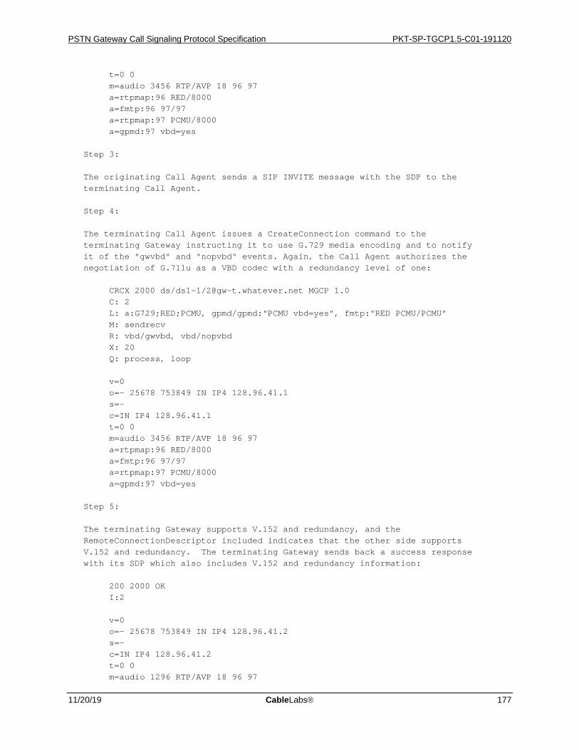
PSTN Gateway Call Signaling Protocol Specification PKT-SP-TGCP1.5-C01-191120
11/20/19 CableLabs 177
t=0 0 m=audio 3456 RTP/AVP 18 96 97 a=rtpmap:96 RED/8000 a=fmtp:96 97/97 a=rtpmap:97 PCMU/8000 a=gpmd:97 vbd=yes Step 3: The originating Call Agent sends a SIP INVITE message with the SDP to the terminating Call Agent. Step 4: The terminating Call Agent issues a CreateConnection command to the terminating Gateway instructing it to use G.729 media encoding and to notify it of the "gwvbd" and "nopvbd" events. Again, the Call Agent authorizes the negotiation of G.711u as a VBD codec with a redundancy level of one: CRCX 2000 ds/ds1-1/[email protected] MGCP 1.0 C: 2 L: a:G729;RED;PCMU, gpmd/gpmd:"PCMU vbd=yes", fmtp:"RED PCMU/PCMU" M: sendrecv R: vbd/gwvbd, vbd/nopvbd X: 20 Q: process, loop v=0 o=- 25678 753849 IN IP4 128.96.41.1 s=- c=IN IP4 128.96.41.1 t=0 0 m=audio 3456 RTP/AVP 18 96 97 a=rtpmap:96 RED/8000 a=fmtp:96 97/97 a=rtpmap:97 PCMU/8000 a=gpmd:97 vbd=yes Step 5: The terminating Gateway supports V.152 and redundancy, and the RemoteConnectionDescriptor included indicates that the other side supports V.152 and redundancy. The terminating Gateway sends back a success response with its SDP which also includes V.152 and redundancy information: 200 2000 OK I:2 v=0 o=- 25678 753849 IN IP4 128.96.41.2 s=- c=IN IP4 128.96.41.2 t=0 0 m=audio 1296 RTP/AVP 18 96 97
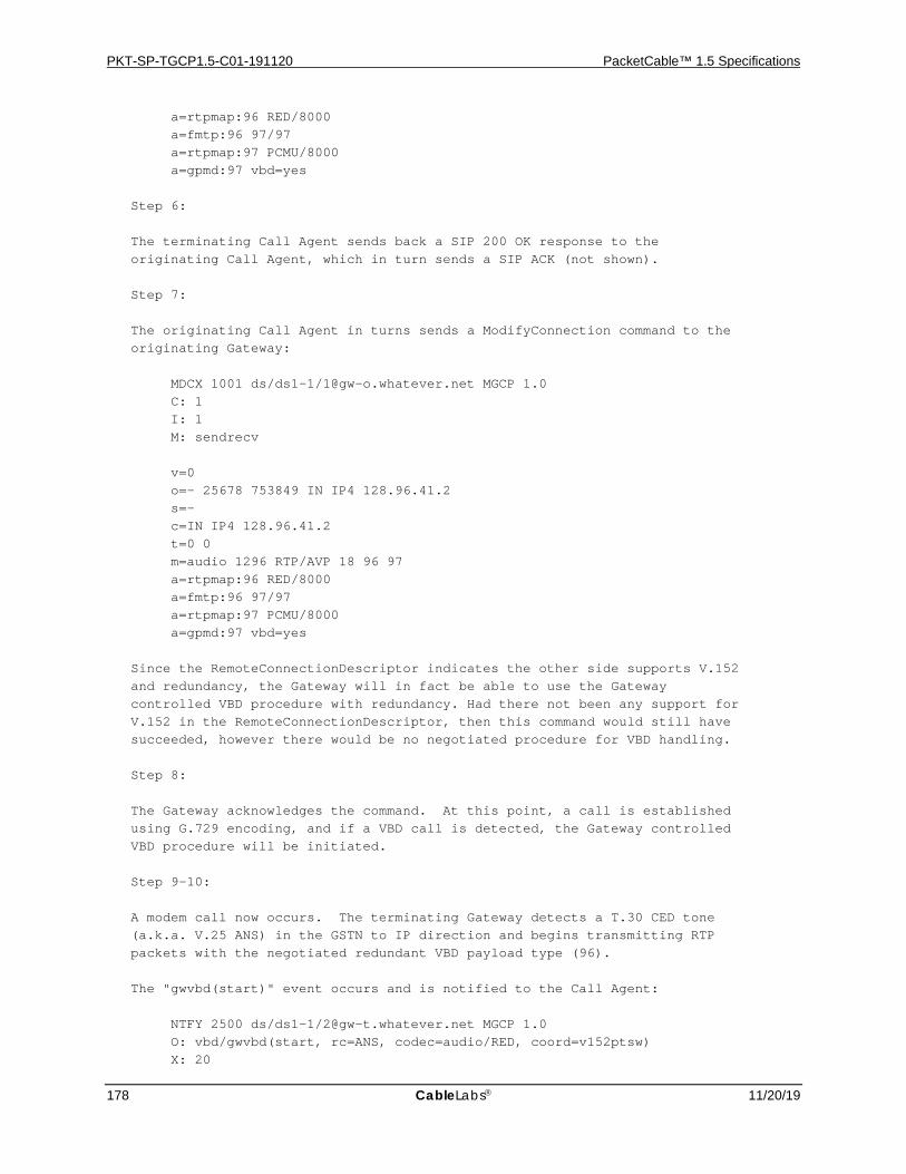
PKT-SP-TGCP1.5-C01-191120 PacketCable™ 1.5 Specifications
178 CableLabs 11/20/19
a=rtpmap:96 RED/8000 a=fmtp:96 97/97 a=rtpmap:97 PCMU/8000 a=gpmd:97 vbd=yes Step 6: The terminating Call Agent sends back a SIP 200 OK response to the originating Call Agent, which in turn sends a SIP ACK (not shown). Step 7: The originating Call Agent in turns sends a ModifyConnection command to the originating Gateway: MDCX 1001 ds/ds1-1/[email protected] MGCP 1.0 C: 1 I: 1 M: sendrecv v=0 o=- 25678 753849 IN IP4 128.96.41.2 s=- c=IN IP4 128.96.41.2 t=0 0 m=audio 1296 RTP/AVP 18 96 97 a=rtpmap:96 RED/8000 a=fmtp:96 97/97 a=rtpmap:97 PCMU/8000 a=gpmd:97 vbd=yes Since the RemoteConnectionDescriptor indicates the other side supports V.152 and redundancy, the Gateway will in fact be able to use the Gateway controlled VBD procedure with redundancy. Had there not been any support for V.152 in the RemoteConnectionDescriptor, then this command would still have succeeded, however there would be no negotiated procedure for VBD handling. Step 8: The Gateway acknowledges the command. At this point, a call is established using G.729 encoding, and if a VBD call is detected, the Gateway controlled VBD procedure will be initiated. Step 9-10: A modem call now occurs. The terminating Gateway detects a T.30 CED tone (a.k.a. V.25 ANS) in the GSTN to IP direction and begins transmitting RTP packets with the negotiated redundant VBD payload type (96). The "gwvbd(start)" event occurs and is notified to the Call Agent: NTFY 2500 ds/ds1-1/[email protected] MGCP 1.0 O: vbd/gwvbd(start, rc=ANS, codec=audio/RED, coord=v152ptsw) X: 20
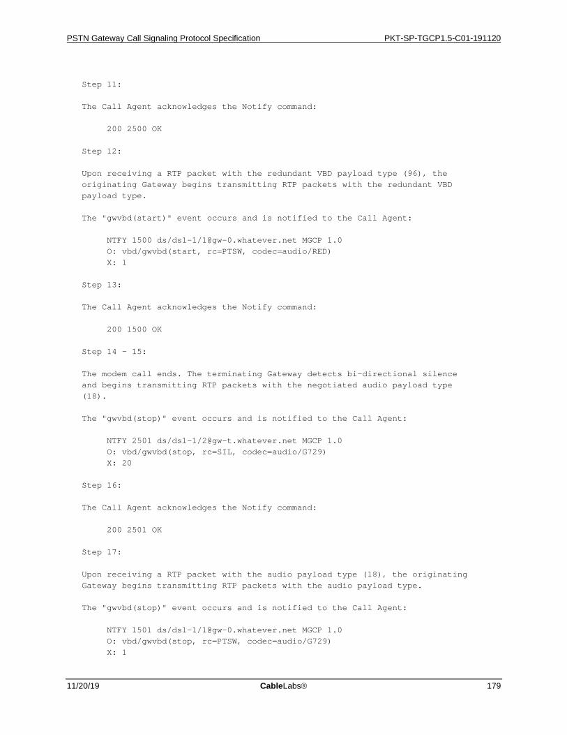
PSTN Gateway Call Signaling Protocol Specification PKT-SP-TGCP1.5-C01-191120
11/20/19 CableLabs 179
Step 11: The Call Agent acknowledges the Notify command: 200 2500 OK Step 12: Upon receiving a RTP packet with the redundant VBD payload type (96), the originating Gateway begins transmitting RTP packets with the redundant VBD payload type. The "gwvbd(start)" event occurs and is notified to the Call Agent: NTFY 1500 ds/ds1-1/[email protected] MGCP 1.0 O: vbd/gwvbd(start, rc=PTSW, codec=audio/RED) X: 1 Step 13: The Call Agent acknowledges the Notify command: 200 1500 OK Step 14 - 15: The modem call ends. The terminating Gateway detects bi-directional silence and begins transmitting RTP packets with the negotiated audio payload type (18). The "gwvbd(stop)" event occurs and is notified to the Call Agent: NTFY 2501 ds/ds1-1/[email protected] MGCP 1.0 O: vbd/gwvbd(stop, rc=SIL, codec=audio/G729) X: 20 Step 16: The Call Agent acknowledges the Notify command: 200 2501 OK Step 17: Upon receiving a RTP packet with the audio payload type (18), the originating Gateway begins transmitting RTP packets with the audio payload type. The "gwvbd(stop)" event occurs and is notified to the Call Agent: NTFY 1501 ds/ds1-1/[email protected] MGCP 1.0 O: vbd/gwvbd(stop, rc=PTSW, codec=audio/G729) X: 1
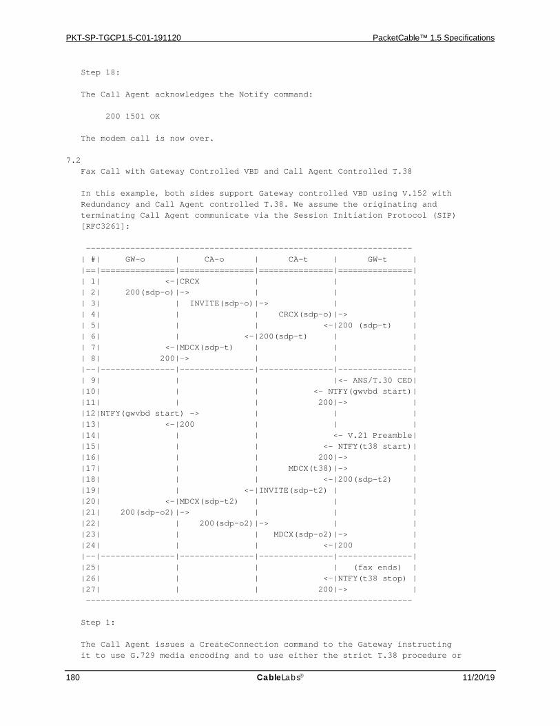
PKT-SP-TGCP1.5-C01-191120 PacketCable™ 1.5 Specifications
180 CableLabs 11/20/19
Step 18: The Call Agent acknowledges the Notify command: 200 1501 OK The modem call is now over. 7.2 Fax Call with Gateway Controlled VBD and Call Agent Controlled T.38 In this example, both sides support Gateway controlled VBD using V.152 with Redundancy and Call Agent controlled T.38. We assume the originating and terminating Call Agent communicate via the Session Initiation Protocol (SIP) [RFC3261]: ------------------------------------------------------------------ | #| GW-o | CA-o | CA-t | GW-t | |==|===============|===============|===============|===============| | 1| <-|CRCX | | | | 2| 200(sdp-o)|-> | | | | 3| | INVITE(sdp-o)|-> | | | 4| | | CRCX(sdp-o)|-> | | 5| | | <-|200 (sdp-t) | | 6| | <-|200(sdp-t) | | | 7| <-|MDCX(sdp-t) | | | | 8| 200|-> | | | |--|---------------|---------------|---------------|---------------| | 9| | | |<- ANS/T.30 CED| |10| | | <- NTFY(gwvbd start)| |11| | | 200|-> | |12|NTFY(gwvbd start) -> | | | |13| <-|200 | | | |14| | | <- V.21 Preamble| |15| | | <- NTFY(t38 start)| |16| | | 200|-> | |17| | | MDCX(t38)|-> | |18| | | <-|200(sdp-t2) | |19| | <-|INVITE(sdp-t2) | | |20| <-|MDCX(sdp-t2) | | | |21| 200(sdp-o2)|-> | | | |22| | 200(sdp-o2)|-> | | |23| | | MDCX(sdp-o2)|-> | |24| | | <-|200 | |--|---------------|---------------|---------------|---------------| |25| | | | (fax ends) | |26| | | <-|NTFY(t38 stop) | |27| | | 200|-> | ------------------------------------------------------------------ Step 1: The Call Agent issues a CreateConnection command to the Gateway instructing it to use G.729 media encoding and to use either the strict T.38 procedure or

PSTN Gateway Call Signaling Protocol Specification PKT-SP-TGCP1.5-C01-191120
11/20/19 CableLabs 181
the Gateway procedure. Consequently, the Call Agent requests notification of the "t38", "gwfax", "gwvbd" and "nopvbd" events. The Call Agent authorizes the negotiation of G.711u as a VBD codec with a redundancy level of one: CRCX 1000 ds/ds1-1/[email protected] MGCP 1.0 C: 1 L: a:G729;RED;PCMU, gpmd/gpmd:"PCMU vbd=yes", fmtp:"RED PCMU/PCMU", fxr/fx:t38;gw M: recvonly R: fxr/t38, fxr/gwfax, vbd/gwvbd, vbd/nopvbd X: 1 Q: process, loop Step 2: The Gateway acknowledges the command and includes SDP with codec information as well as capability, V.152 and redundancy information: 200 1000 OK I:1 v=0 o=- 25678 753849 IN IP4 128.96.41.1 s=- c=IN IP4 128.96.41.1 t=0 0 a=pmft: T38 m=audio 3456 RTP/AVP 18 96 97 a=rtpmap:96 RED/8000 a=fmtp:96 97/97 a=rtpmap:97 PCMU/8000 a=gpmd:97 vbd=yes a=sqn: 0 a=cdsc: 1 audio RTP/AVP 18 96 97 a=cdsc: 4 image udptl t38 Note that V.152 requires the use of the session-level "a=pmft" SDP attribute in order to express a preference for T.38 over V.152 for fax handling. Step 3: The originating Call Agent sends a SIP INVITE message with the SDP to the terminating Call Agent. Step 4: The terminating Call Agent issues a CreateConnection command to the terminating Gateway instructing it to use G.729 media encoding and to use either the strict T.38 procedure or the Gateway procedure. Consequently, the Call Agent requests notification of the "t38", "gwfax", "gwvbd" and "nopvbd" events. Again, the Call Agent authorizes the negotiation of G.711u as a VBD codec with a redundancy level of one: CRCX 2000 ds/ds1-1/[email protected] MGCP 1.0
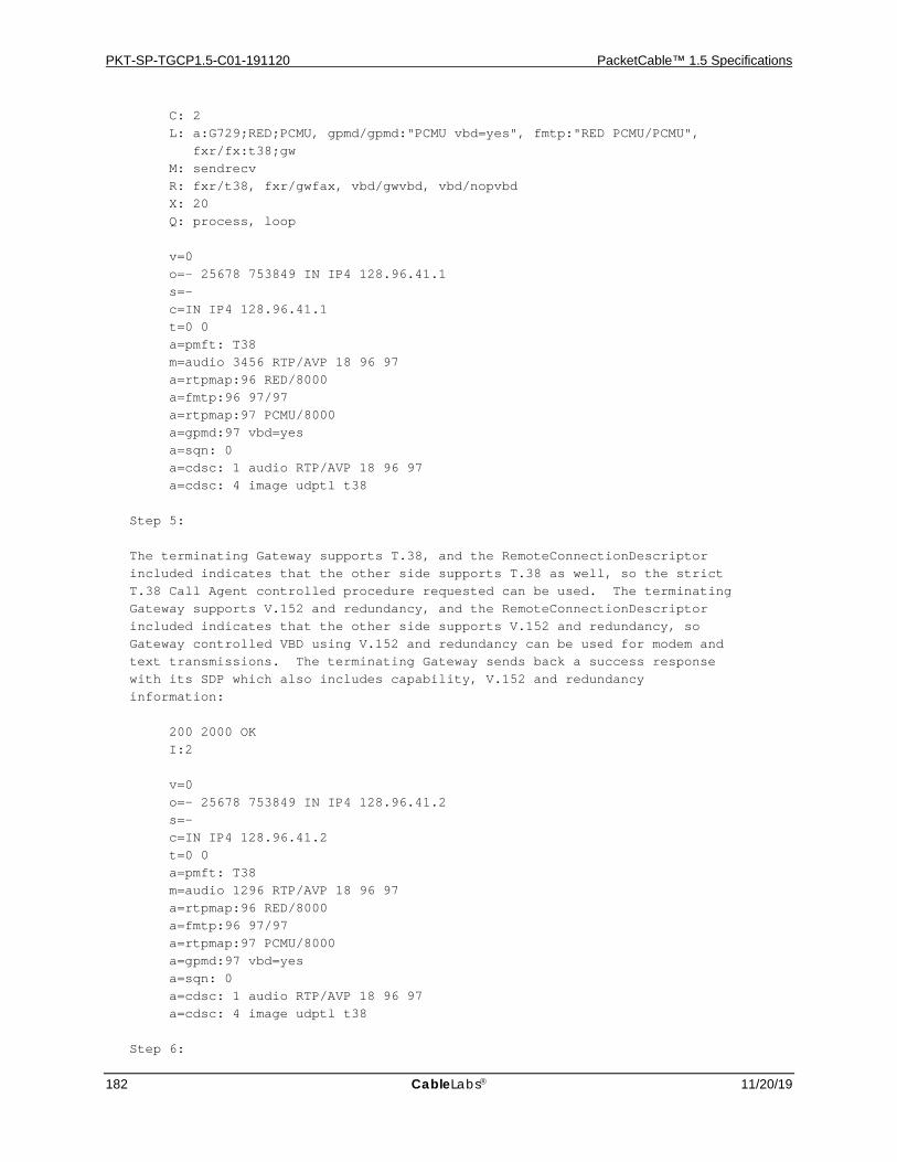
PKT-SP-TGCP1.5-C01-191120 PacketCable™ 1.5 Specifications
182 CableLabs 11/20/19
C: 2 L: a:G729;RED;PCMU, gpmd/gpmd:"PCMU vbd=yes", fmtp:"RED PCMU/PCMU", fxr/fx:t38;gw M: sendrecv R: fxr/t38, fxr/gwfax, vbd/gwvbd, vbd/nopvbd X: 20 Q: process, loop v=0 o=- 25678 753849 IN IP4 128.96.41.1 s=- c=IN IP4 128.96.41.1 t=0 0 a=pmft: T38 m=audio 3456 RTP/AVP 18 96 97 a=rtpmap:96 RED/8000 a=fmtp:96 97/97 a=rtpmap:97 PCMU/8000 a=gpmd:97 vbd=yes a=sqn: 0 a=cdsc: 1 audio RTP/AVP 18 96 97 a=cdsc: 4 image udptl t38 Step 5: The terminating Gateway supports T.38, and the RemoteConnectionDescriptor included indicates that the other side supports T.38 as well, so the strict T.38 Call Agent controlled procedure requested can be used. The terminating Gateway supports V.152 and redundancy, and the RemoteConnectionDescriptor included indicates that the other side supports V.152 and redundancy, so Gateway controlled VBD using V.152 and redundancy can be used for modem and text transmissions. The terminating Gateway sends back a success response with its SDP which also includes capability, V.152 and redundancy information: 200 2000 OK I:2 v=0 o=- 25678 753849 IN IP4 128.96.41.2 s=- c=IN IP4 128.96.41.2 t=0 0 a=pmft: T38 m=audio 1296 RTP/AVP 18 96 97 a=rtpmap:96 RED/8000 a=fmtp:96 97/97 a=rtpmap:97 PCMU/8000 a=gpmd:97 vbd=yes a=sqn: 0 a=cdsc: 1 audio RTP/AVP 18 96 97 a=cdsc: 4 image udptl t38 Step 6:
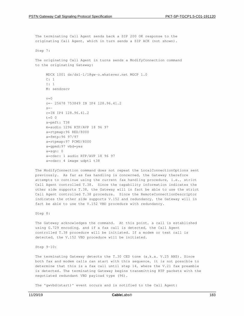
PSTN Gateway Call Signaling Protocol Specification PKT-SP-TGCP1.5-C01-191120
11/20/19 CableLabs 183
The terminating Call Agent sends back a SIP 200 OK response to the originating Call Agent, which in turn sends a SIP ACK (not shown). Step 7: The originating Call Agent in turns sends a ModifyConnection command to the originating Gateway: MDCX 1001 ds/ds1-1/[email protected] MGCP 1.0 C: 1 I: 1 M: sendrecv v=0 o=- 25678 753849 IN IP4 128.96.41.2 s=- c=IN IP4 128.96.41.2 t=0 0 a=pmft: T38 m=audio 1296 RTP/AVP 18 96 97 a=rtpmap:96 RED/8000 a=fmtp:96 97/97 a=rtpmap:97 PCMU/8000 a=gpmd:97 vbd=yes a=sqn: 0 a=cdsc: 1 audio RTP/AVP 18 96 97 a=cdsc: 4 image udptl t38 The ModifyConnection command does not repeat the LocalConnectionOptions sent previously. As far as fax handling is concerned, the Gateway therefore attempts to continue using the current fax handling procedure, i.e., strict Call Agent controlled T.38. Since the capability information indicates the other side supports T.38, the Gateway will in fact be able to use the strict Call Agent controlled T.38 procedure. Since the RemoteConnectionDescriptor indicates the other side supports V.152 and redundancy, the Gateway will in fact be able to use the V.152 VBD procedure with redundancy. Step 8: The Gateway acknowledges the command. At this point, a call is established using G.729 encoding, and if a fax call is detected, the Call Agent controlled T.38 procedure will be initiated. If a modem or text call is detected, the V.152 VBD procedure will be initiated. Step 9-10: The terminating Gateway detects the T.30 CED tone (a.k.a. V.25 ANS). Since both fax and modem calls can start with this sequence, it is not possible to determine that this is a fax call until step 14, where the V.21 fax preamble is detected. The terminating Gateway begins transmitting RTP packets with the negotiated redundant VBD payload type (96). The "gwvbd(start)" event occurs and is notified to the Call Agent:
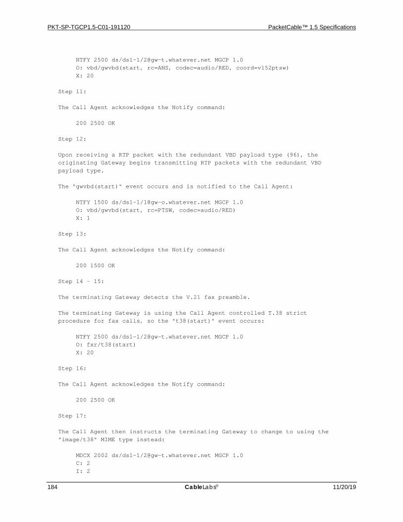
PKT-SP-TGCP1.5-C01-191120 PacketCable™ 1.5 Specifications
184 CableLabs 11/20/19
NTFY 2500 ds/ds1-1/[email protected] MGCP 1.0 O: vbd/gwvbd(start, rc=ANS, codec=audio/RED, coord=v152ptsw) X: 20 Step 11: The Call Agent acknowledges the Notify command: 200 2500 OK Step 12: Upon receiving a RTP packet with the redundant VBD payload type (96), the originating Gateway begins transmitting RTP packets with the redundant VBD payload type. The "gwvbd(start)" event occurs and is notified to the Call Agent: NTFY 1500 ds/ds1-1/[email protected] MGCP 1.0 O: vbd/gwvbd(start, rc=PTSW, codec=audio/RED) X: 1 Step 13: The Call Agent acknowledges the Notify command: 200 1500 OK Step 14 - 15: The terminating Gateway detects the V.21 fax preamble. The terminating Gateway is using the Call Agent controlled T.38 strict procedure for fax calls, so the "t38(start)" event occurs: NTFY 2500 ds/ds1-1/[email protected] MGCP 1.0 O: fxr/t38(start) X: 20 Step 16: The Call Agent acknowledges the Notify command: 200 2500 OK Step 17: The Call Agent then instructs the terminating Gateway to change to using the "image/t38" MIME type instead: MDCX 2002 ds/ds1-1/[email protected] MGCP 1.0 C: 2 I: 2
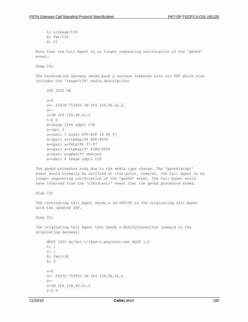
PSTN Gateway Call Signaling Protocol Specification PKT-SP-TGCP1.5-C01-191120
11/20/19 CableLabs 185
L: a:image/t38 R: fxr/t38 X: 21 Note that the Call Agent is no longer requesting notification of the "gwvbd" event. Step 18: The terminating Gateway sends back a success response with its SDP which also includes the "image/t38" media description: 200 2002 OK v=0 o=- 25678 753850 IN IP4 128.96.41.2 s=- c=IN IP4 128.96.41.2 t=0 0 m=image 1296 udptl t38 a=sqn: 0 a=cdsc: 1 audio RTP/AVP 18 96 97 a=cpar: a=rtpmap:96 RED/8000 a=cpar: a=fmtp:96 97/97 a=cpar: a=rtpmap:97 PCMU/8000 a=cpar: a=gpmd:97 vbd=yes a=cdsc: 4 image udptl t38 The gwvbd procedure ends due to the media type change. The "gwvbd(stop)" event would normally be notified at this point, however, the Call Agent is no longer requesting notification of the "gwvbd" event. The Call Agent would have inferred from the "t38(start)" event that the gwvbd procedure ended. Step 19: The terminating Call Agent sends a re-INVITE to the originating Call Agent with the updated SDP. Step 20: The originating Call Agent then sends a ModifyConnection command to the originating Gateway: MDCX 1003 ds/ds1-1/[email protected] MGCP 1.0 C: 1 I: 1 R: fxr/t38 X: 2 v=0 o=- 25678 753850 IN IP4 128.96.41.2 s=- c=IN IP4 128.96.41.2 t=0 0
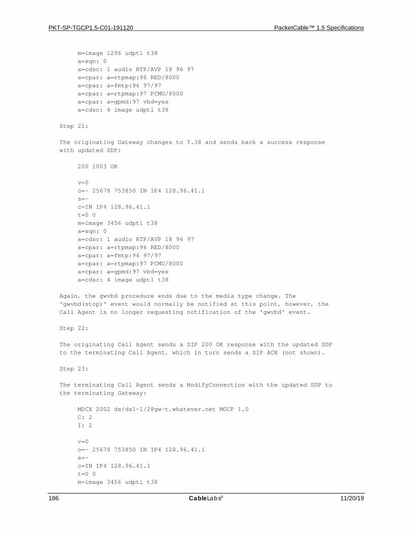
PKT-SP-TGCP1.5-C01-191120 PacketCable™ 1.5 Specifications
186 CableLabs 11/20/19
m=image 1296 udptl t38 a=sqn: 0 a=cdsc: 1 audio RTP/AVP 18 96 97 a=cpar: a=rtpmap:96 RED/8000 a=cpar: a=fmtp:96 97/97 a=cpar: a=rtpmap:97 PCMU/8000 a=cpar: a=gpmd:97 vbd=yes a=cdsc: 4 image udptl t38 Step 21: The originating Gateway changes to T.38 and sends back a success response with updated SDP: 200 1003 OK v=0 o=- 25678 753850 IN IP4 128.96.41.1 s=- c=IN IP4 128.96.41.1 t=0 0 m=image 3456 udptl t38 a=sqn: 0 a=cdsc: 1 audio RTP/AVP 18 96 97 a=cpar: a=rtpmap:96 RED/8000 a=cpar: a=fmtp:96 97/97 a=cpar: a=rtpmap:97 PCMU/8000 a=cpar: a=gpmd:97 vbd=yes a=cdsc: 4 image udptl t38 Again, the gwvbd procedure ends due to the media type change. The "gwvbd(stop)" event would normally be notified at this point, however, the Call Agent is no longer requesting notification of the "gwvbd" event. Step 22: The originating Call Agent sends a SIP 200 OK response with the updated SDP to the terminating Call Agent, which in turn sends a SIP ACK (not shown). Step 23: The terminating Call Agent sends a ModifyConnection with the updated SDP to the terminating Gateway: MDCX 2002 ds/ds1-1/[email protected] MGCP 1.0 C: 2 I: 2 v=0 o=- 25678 753850 IN IP4 128.96.41.1 s=- c=IN IP4 128.96.41.1 t=0 0 m=image 3456 udptl t38
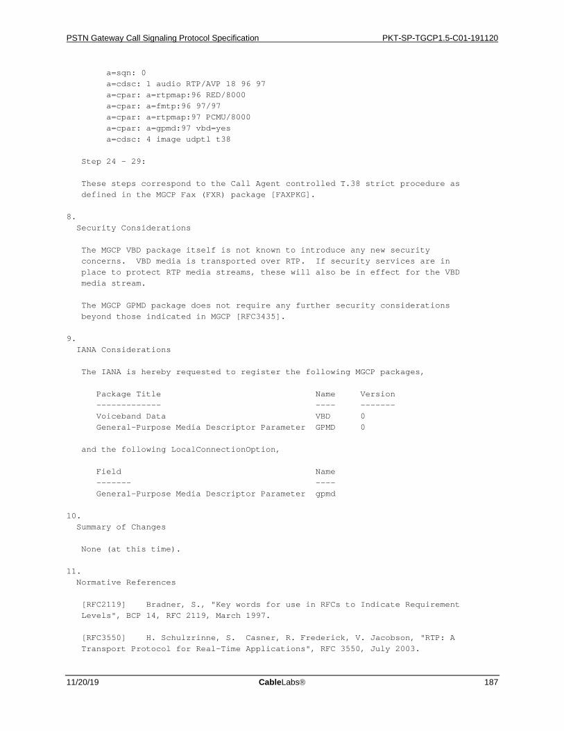
PSTN Gateway Call Signaling Protocol Specification PKT-SP-TGCP1.5-C01-191120
11/20/19 CableLabs 187
a=sqn: 0 a=cdsc: 1 audio RTP/AVP 18 96 97 a=cpar: a=rtpmap:96 RED/8000 a=cpar: a=fmtp:96 97/97 a=cpar: a=rtpmap:97 PCMU/8000 a=cpar: a=gpmd:97 vbd=yes a=cdsc: 4 image udptl t38 Step 24 – 29: These steps correspond to the Call Agent controlled T.38 strict procedure as defined in the MGCP Fax (FXR) package [FAXPKG]. 8. Security Considerations The MGCP VBD package itself is not known to introduce any new security concerns. VBD media is transported over RTP. If security services are in place to protect RTP media streams, these will also be in effect for the VBD media stream. The MGCP GPMD package does not require any further security considerations beyond those indicated in MGCP [RFC3435]. 9. IANA Considerations The IANA is hereby requested to register the following MGCP packages, Package Title Name Version ------------- ---- ------- Voiceband Data VBD 0 General-Purpose Media Descriptor Parameter GPMD 0 and the following LocalConnectionOption, Field Name ------- ---- General-Purpose Media Descriptor Parameter gpmd 10. Summary of Changes None (at this time). 11. Normative References [RFC2119] Bradner, S., "Key words for use in RFCs to Indicate Requirement Levels", BCP 14, RFC 2119, March 1997. [RFC3550] H. Schulzrinne, S. Casner, R. Frederick, V. Jacobson, "RTP: A Transport Protocol for Real-Time Applications", RFC 3550, July 2003.

PKT-SP-TGCP1.5-C01-191120 PacketCable™ 1.5 Specifications
188 CableLabs 11/20/19
[RFC3435] F. Andreasen, B. Foster, "Media Gateway Control Protocol (MGCP) Version 1.0", RFC 3435, January 2003. [RFC2198] C. Perkins, I. Kouvelas, O. Hodson, V. Hardman, M. Handley, J.C. Bolot, A. Vega-Garcia, S. Fosse-Parisis, "RTP Payload for Redundant Audio Data", RFC 2198, September 1997. [RFC2327] M. Handley, V. Jacobson, "SDP: Session Description Protocol", RFC 2327, April 1998. [V1501] ITU-T Recommendation V.150.1, “Modem-over-IP networks: Procedures for the end-to-end connection of V-series DCEs”, 01/2003. [V152] ITU-T Recommendation V.152, "Procedures for supporting Voice- Band Data over IP Networks", 01/2005. [RFC2833] H. Schulzrinne, S. Petrack, "RTP Payload for DTMF Digits, Telephony Tones and Telephony Signals", RFC 2833, May 2000. [FAXPKG] F. Andreasen, "Media Gateway Control Protocol Fax Package", draft-andreasen-mgcp-fax-04.txt, March 23, 2005. [FMPKG] B. Foster, F. Andreasen, "Basic Media Gateway Control Protocol (MGCP) Packages", RFC 3660, December 2003. [H2482] ITU-T Recommendation H.248.2, "Gateway control protocol: Facsimile, text conversation and call discrimination packages", 11/2000. [H1501A1] ITU-T Recommendation V.150.1 Amendment 1, "Modem-over-IP networks: Procedures for the end-to-end connection of V-series DCEs, Amendment 1: Modification to SSE reason identifier codes to support voice band data and text relay", 01/2005. [RFC2234] D. Crocker, P. Overell, "Augmented BNF for Syntax Specifications: ABNF", RFC 2234, November 1997. [RFC2733] J. Rosenberg, H. Schulzrinne, "An RTP Payload Format for Generic Forward Error Correction", RFC 2733, December 1999. 12. Informative References [RFC3261] J. Rosenberg, H. Schulzrinne, G. Camarillo, A. Johnston, J. Peterson, R. Sparks, M. Handley, E. Schooler, "SIP: Session Initiation Protocol", RFC 3261, June 2002. [T38] ITU-T Recommendation T.38, "Procedures for real-time Group 3 facsimile communication over IP networks", 04/2004. [RFC2793] G. Hellstrom, "RTP Payload for Text Conversation", RFC 2793, May 2000. 13. Acknowledgements

PSTN Gateway Call Signaling Protocol Specification PKT-SP-TGCP1.5-C01-191120
11/20/19 CableLabs 189
Several people have contributed to the development of the MGCP VBD and GPMD packages and the use of the MIME subtypes "RED" and "parityfec" with the FM package for VBD with redundancy and FEC. In particular, the authors would like to thank Flemming Andreasen, John Atkinson, Bill Foster and the CableLabs PacketCable TGCP/NCS focus team for their contributions. 14. Author's Address Joe Stone Cisco Systems 2200 East President George Bush Highway Richardson, Texas 75082 Email: [email protected] Rajesh Kumar Cisco Systems 771 Alder Drive Milpitas, California 95035 Email: [email protected]
PKT-SP-TGCP1.5-C01-191120 PacketCable™ 1.5 Specifications
190 CableLabs 11/20/19
Appendix B. Mode Interactions An MGCP connection can establish one or more media streams. These streams are either incoming (from a remote endpoint) or outgoing (generated at the circuit endpoint). The "connection mode" parameter establishes the direction and generation of these streams. When there is only one connection to an endpoint, the mapping of these streams is straightforward; the circuit endpoint plays the incoming stream over the circuit and generates the outgoing stream from the circuit signal, depending on the mode parameter.
However, when several connections are established to an endpoint, there can be many incoming and outgoing streams. Depending on the connection mode used, these streams may interact differently with each other and the streams going to/from the endpoint.
Table 24 below describes how different connections should be mixed when one or more connections are concurrently "active". An active connection is here defined as a connection that is in one of the following modes:
• "send/receive"
• "send only"
• "receive only"
Connections in "network loopback", "network continuity test", or "inactive" modes are not affected by connections in the "active" modes. Table 24 uses the following conventions:
• Ain is the incoming media stream from Connection A
• Bin is the incoming media stream from Connection B
• Hin is the incoming media stream from the Trunk
• Aout is the outgoing media stream to Connection A
• Bout is the outgoing media stream to Connection B
• Hout is the outgoing media stream to the endpoint, where "cot" indicates continuity test, whether in the "continuity test" or "loopback" mode.
• NA indicates No Stream whatever
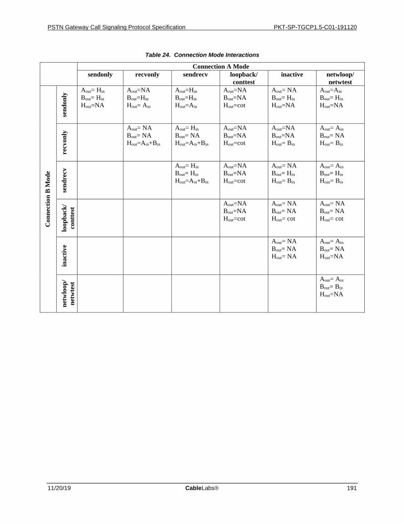
PSTN Gateway Call Signaling Protocol Specification PKT-SP-TGCP1.5-C01-191120
11/20/19 CableLabs 191
Table 24. Connection Mode Interactions
Connection A Mode sendonly recvonly sendrecv loopback/
conttest inactive netwloop/
netwtest
Con
nect
ion
B M
ode
send
only
Aout= Hin Bout= Hin Hout=NA
Aout=NA Bout=Hin Hout= Ain
Aout=Hin Bout=Hin Hout=Ain
Aout=NA Bout=NA Hout=cot
Aout= NA Bout= Hin Hout=NA
Aout=Ain Bout= Hin Hout=NA
recv
only
Aout= NA Bout= NA Hout=Ain+Bin
Aout= Hin Bout= NA Hout=Ain+Bin
Aout=NA Bout=NA Hout=cot
Aout=NA Bout=NA Hout= Bin
Aout= Ain Bout= NA Hout= Bin
send
recv
Aout= Hin Bout= Hin Hout=Ain+Bin
Aout=NA Bout=NA Hout=cot
Aout= NA Bout= Hin Hout= Bin
Aout= Ain Bout= Hin Hout= Bin
loop
back
/co
ntte
st Aout=NA
Bout=NA Hout=cot
Aout= NA Bout= NA Hout= cot
Aout= NA Bout= NA Hout= cot
inac
tive
Aout= NA Bout= NA Hout= NA
Aout= Ain Bout= NA Hout=NA
netw
loop
/ ne
twte
st Aout= Ain
Bout= Bin Hout=NA
PKT-SP-TGCP1.5-C01-191120 PacketCable™ 1.5 Specifications
192 CableLabs 11/20/19
Appendix C. Example Command Encodings This appendix provides examples of commands and responses shown with the actual encoding used. Examples are provided for each command. All commentary shown in the commands and responses is optional.
C.1 NotificationRequest The first example illustrates a NotificationRequest that will initiate a continuity test and look for the verification of the test. The "notified entity" for the endpoint will be set to "[email protected]:5678" and the RequestIdentifier will be repeated in the corresponding Notify command:
RQNT 1201 ds/ds1-1/[email protected] MGCP 1.0 TGCP 1.0 N: [email protected]:5678 X: 0123456789AC R: co1, oc(N), of(N) S: co1
The response indicates that the transaction was successful: 200 1201 OK
C.2 Notify The example below illustrates a Notify message that notifies a successful continuity test as indicated by the observed events. Since a "notified entity" was specified in the triggering NotificationRequest it is repeated here. Also, the RequestIdentifier is included to correlate this Notify command with the NotificationRequest (includes notification request embedded in connection handling primitives) command that triggered:
NTFY 2002 ds/ds1-1/[email protected] MGCP 1.0 TGCP 1.0 N: [email protected]:5678 X: 0123456789AC O: co1
The Notify response indicates that the transaction was successful:
200 2002 OK
C.3 CreateConnection The first example illustrates a CreateConnection command to create a connection on the endpoint specified. The connection will be part of the specified CallId. The LocalConnectionOptions specify that G.711 u-law will be the codec used and the packetization period will be 10 ms. The connection mode will be "receive only":
CRCX 1204 ds/ds1-1/[email protected] MGCP 1.0 TGCP 1.0 C: A3C47F21456789F0 L: p:10, a:PCMU M: recvonly
PSTN Gateway Call Signaling Protocol Specification PKT-SP-TGCP1.5-C01-191120
11/20/19 CableLabs 193
The response indicates that the transaction was successful, and a connection identifier for the newly created connection is therefore included. A session description for the new connection is included as well – note that it is preceded by an empty line.
200 1204 OK I: FDE234C8 v=0 o=- 25678 753849 IN IP4 128.96.41.1 s=- c=IN IP4 128.96.41.1 t=0 0 m=audio 3456 RTP/AVP 0 a=mptime:10
The second example illustrates a CreateConnection command containing a notification request and a RemoteConnectionDescriptor:
CRCX 1205 ds/ds1-1/[email protected] MGCP 1.0 TGCP 1.0 C: A3C47F21456789F0 L: p:10, a:PCMU M: recvonly X: 0123456789AD R: MO/sup(addr(K0, 4,1,1, s2), id(K0,0,0,7,3,2,5,5,5,1,2,3,4,s0)) S: MO/ans
v=0 o=- 25678 753849 IN IP4 128.96.41.1 s=- c=IN IP4 128.96.41.1 t=0 0 m=audio 3456 RTP/AVP 0 a=mptime:10
The response indicates that the transaction failed, because the trunk was already seized. Consequently, neither a connection-id nor a session description is returned:
401 2005 Circuit already seized
Our third example illustrates the use of the provisional response and the three-way handshake:
CRCX 1206 ds/ds1-1/[email protected] MGCP 1.0 TGCP 1.0 K: 1205 C: A3C47F21456789F0 L: p:10, a:PCMU M: inactive v=0 o=- 25678 753849 IN IP4 128.96.41.1 s=- c=IN IP4 128.96.41.1 t=0 0 m=audio 3456 RTP/AVP 0 18 a=mptime:10 10
A provisional response is returned initially: 100 1206 Pending I: DFE233D1 v=0 o=- 4723891 7428910 IN IP4 128.96.63.25 s=- c=IN IP4 128.96.63.25
PKT-SP-TGCP1.5-C01-191120 PacketCable™ 1.5 Specifications
194 CableLabs 11/20/19
t=0 0 m=audio 3456 RTP/AVP 0 a=mptime:10
Note that the endpoint elected to support only the PCMU codec, i.e., payload number 0.
A little later, the final response is received: 200 1206 OK K: I: DFE233D1 v=0 o=- 4723891 7428910 IN IP4 128.96.63.25 s=- c=IN IP4 128.96.63.25 t=0 0 m=audio 3456 RTP/AVP 0 a=mptime:10
The Media Gateway Controller acknowledges the final response as requested:
000 1206
and the transaction is complete.
C.4 ModifyConnection The first example shows a ModifyConnection command that simply sets the connection mode of a connection to "send/receive" – the "notified entity" is set as well:
MDCX 1209 ds/ds1-1/[email protected] MGCP 1.0 TGCP 1.0 C: A3C47F21456789F0 I: FDE234C8 N: [email protected] M: sendrecv
The response indicates that the transaction was successful:
200 1209 OK
In the second example, we pass a session description and include a notification request with the ModifyConnection command. The endpoint will start playing ring-back tones to the PSTN until it detects audio on the connection specified for the ring-back signal:
MDCX 1210 ds/ds1-1/[email protected] MGCP 1.0 TGCP 1.0 C: A3C47F21456789F0 I: FDE234C8 M: recvonly X: 0123456789AE R: ma@ FDE234C8 S: rt v=0 o=- 4723891 7428910 IN IP4 128.96.63.25 s=- c=IN IP4 128.96.63.25 t=0 0 m=audio 3456 RTP/AVP 0 a=mptime:10
The response indicates that the transaction was successful:
200 1206 OK
PSTN Gateway Call Signaling Protocol Specification PKT-SP-TGCP1.5-C01-191120
11/20/19 CableLabs 195
C.5 DeleteConnection (From the Media Gateway Controller) In this example, the Media Gateway Controller simply instructs the trunking gateway to delete the connection FDE234C8 on the endpoint specified:
DLCX 1210 ds/ds1-1/[email protected] MGCP 1.0 TGCP 1.0 C: A3C47F21456789F0 I: FDE234C8
The response indicates success, and that the connection was deleted. Connection parameters for the connection are therefore included as well:
250 1210 OK P: PS=1245, OS=62345, PR=780, OR=45123, PL=10, JI=27, LA=48
C.6 DeleteConnection (From the Trunking gateway) In this example, the trunking gateway sends a DeleteConnection command to the Media Gateway Controller to instruct it that a connection on the specified endpoint has been deleted. The ReasonCode specifies the reason for the deletion, and Connection Parameters for the connection are provided as well:
DLCX 1210 ds/ds1-1/[email protected] MGCP 1.0 TGCP 1.0 C: A3C47F21456789F0 I: FDE234C8 E: 900 – Hardware error P: PS=1245, OS=62345, PR=780, OR=45123, PL=10, JI=27, LA=48
The Media Gateway Controller sends a success response to the gateway:
200 1210 OK
C.7 DeleteConnection (Multiple Connections From the Media Gateway Controller)
In the first example, the Media Gateway Controller instructs the trunking gateway to delete all connections related to call "A3C47F21456789F0" on the specified endpoint:
DLCX 1210 ds/ds1-1/[email protected] MGCP 1.0 TGCP 1.0 C: A3C47F21456789F0
The response indicates success and that the connection(s) were deleted:
250 1210 OK
In the second example, the Media Gateway Controller instructs the trunking gateway to delete all connections related to all of the endpoints specified:
DLCX 1210 ds/ds1-1/*@tgw-2567.whatever.net MGCP 1.0 TGCP 1.0
The response indicates success:
250 1210 OK
C.8 AuditEndpoint In the first example, the Media Gateway Controller wants to learn what endpoints are present on the trunking gateway specified, hence the use of the "all of" wild-card for the local portion of the endpoint-name. The Media Gateway Controller only wants to two endpoint names:
AUEP 1200 *@tgw-2567.whatever.net MGCP 1.0 TGCP 1.0 ZM: 2
The trunking gateway indicates success and includes a list of up to two endpoint names. A total of 24 endpoint names matched the wildcard specified:

PKT-SP-TGCP1.5-C01-191120 PacketCable™ 1.5 Specifications
196 CableLabs 11/20/19
200 1200 OK Z: ds/ds1-1/[email protected] Z: ds/ds1-1/[email protected] ZN: 24
In the second example, the capabilities of one of the endpoints is requested:
AUEP 1201 ds/ds1-1/[email protected] MGCP 1.0 TGCP 1.0 F: A
The response indicates success and the capabilities as well. Two codecs are supported, however with different capabilities. Consequently, two separate capability sets are returned:
200 1201 OK A: a:PCMU, p:10-100, e:on, s:off, v:IT, m:sendonly;recvonly;sendrecv; inactive;loopback;conttest;netwloop;netwtest A: a:G728, p:30-90, e:on, s:on, v:IT, m: sendonly;recvonly;sendrecv; inactive;loopback;conttest;netwloop
In the third example, the Media Gateway Controller audits all possible information for the endpoint:
AUEP 2002 ds/ds1-1/[email protected] MGCP 1.0 TGCP 1.0 F: R, S,X,N,I,T,O,ES
The response indicates success:
200 2002 OK R: IT/ft,mt(N) S: X: 0123456789B1 N: [128.96.41.12] I: 32F345E2 T: ft O: ES:
The list of requested events contains two events. Where no package name is specified, the default package is assumed. The same goes for actions, so the default action – Notify - must therefore be assumed for the "IT/ft" event. The omission of a value for the "SignalRequests" means there are currently no active signals. The current "notified entity" refers to an IP-address and only a single connection exists for the endpoint. The current value of DetectEvents is "ft", and the list of ObservedEvents is empty as is the EventStates.
C.9 AuditConnection The first example shows an AuditConnection command where we audit the CallId, NotifiedEntity, LocalConnectionOptions, Connection Mode, LocalConnectionDescriptor, and the Connection Parameters:
AUCX 2003 ds/ds1-1/[email protected] MGCP 1.0 TGCP 1.0 I: 32F345E2 F: C,N,L,M,LC,P
The response indicates success and includes information for the RequestedInfo:
200 2003 OK C: A3C47F21456789F0 N: [email protected] L: p:10, a:PCMU M: sendrecv P: PS=395, OS=22850, PR=615, OR=30937, PL=7, JI=26, LA=47 v=0 o=- 4723891 7428910 IN IP4 128.96.63.25 s=- c=IN IP4 128.96.63.25 t=0 0 m=audio 1296 RTP/AVP 0

PSTN Gateway Call Signaling Protocol Specification PKT-SP-TGCP1.5-C01-191120
11/20/19 CableLabs 197
a=mptime:10
In the second example, there is a request to audit RemoteConnectionDescriptor and LocalConnectionDescriptor:
AUCX 1203 ds/ds1-1/[email protected] MGCP 1.0 TGCP 1.0 I: FDE234C8 F: RC,LC
The response indicates success, and includes information for the RequestedInfo. In this case, no RemoteConnectionDescriptor exists, hence only the protocol version field is included for the RemoteConnectionDescriptor:
200 1203 OK v=0 o=- 4723891 7428910 IN IP4 128.96.63.25 s=- c=IN IP4 128.96.63.25 t=0 0 m=audio 1296 RTP/AVP 0 a=mptime:10 v=0
C.10 RestartInProgress The first example illustrates a RestartInProgress message sent by a trunking gateway to inform the Media Gateway Controller that the specified endpoint will be taken out of service in 300 seconds:
RSIP 1200 ds/ds1-1/[email protected] MGCP 1.0 TGCP 1.0 RM: graceful RD: 300
The Media Gateway Controller's response indicates that the transaction was successful:
200 1200 OK
In the second example, the RestartInProgress message sent by the trunking gateway informs the Media Gateway Controller, that all of the trunking gateway's endpoints are being placed in service in 0 seconds, i.e., they are back in service. The delay could have been omitted as well:
RSIP 1204 *@tgw-2567.whatever.net MGCP 1.0 TGCP 1.0 RM: restart RD: 0
The Media Gateway Controller's response indicates success, and furthermore provides the endpoints in question with a new "notified entity":
200 1204 OK N: [email protected]
Alternatively, the command could have failed with a new "notified entity" as in:
521 1204 OK N: [email protected]
In that case, the command would then have to be retried in order to satisfy the "restart procedure" (see Section 7.4.3.5), this time going to Media Gateway Controller "[email protected]".
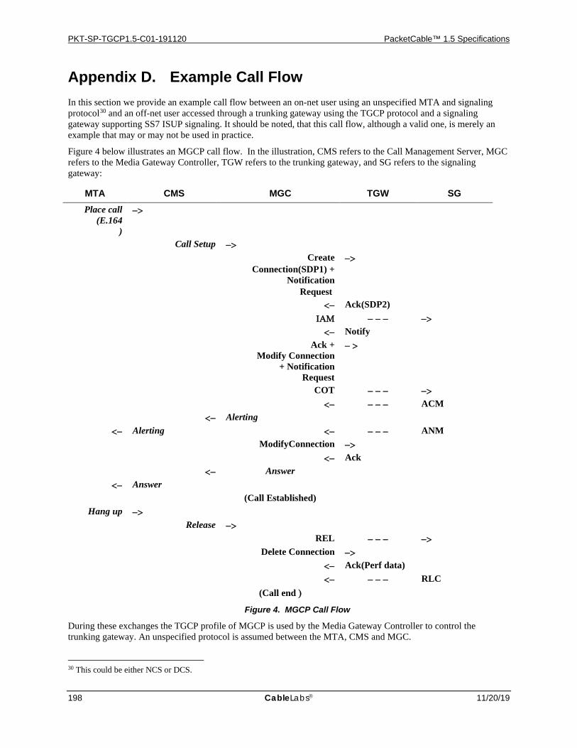
PKT-SP-TGCP1.5-C01-191120 PacketCable™ 1.5 Specifications
198 CableLabs 11/20/19
Appendix D. Example Call Flow In this section we provide an example call flow between an on-net user using an unspecified MTA and signaling protocol30 and an off-net user accessed through a trunking gateway using the TGCP protocol and a signaling gateway supporting SS7 ISUP signaling. It should be noted, that this call flow, although a valid one, is merely an example that may or may not be used in practice.
Figure 4 below illustrates an MGCP call flow. In the illustration, CMS refers to the Call Management Server, MGC refers to the Media Gateway Controller, TGW refers to the trunking gateway, and SG refers to the signaling gateway:
MTA CMS MGC TGW SG Place call
(E.164)
−>
Call Setup −> Create
Connection(SDP1) + Notification
Request
−>
<− Ack(SDP2) ΙΑΜ − − − −> <− Notify Ack +
Modify Connection + Notification
Request
− >
COT − − − −> <− − − − ACM <− Alerting
<− Alerting <− − − − ANM ModifyConnection −> <− Ack <− Answer
<− Answer (Call Established)
Hang up −> Release −> REL − − − −> Delete Connection −> <− Ack(Perf data) <− − − − RLC (Call end )
Figure 4. MGCP Call Flow
During these exchanges the TGCP profile of MGCP is used by the Media Gateway Controller to control the trunking gateway. An unspecified protocol is assumed between the MTA, CMS and MGC.
30 This could be either NCS or DCS.
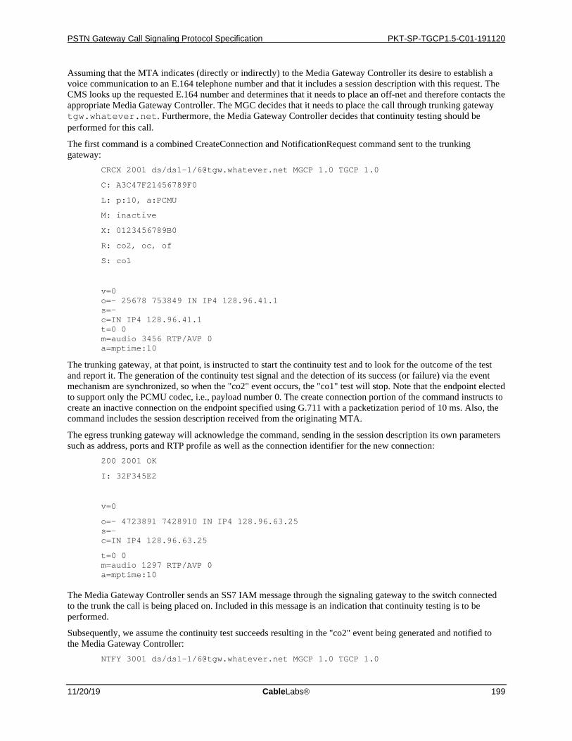
PSTN Gateway Call Signaling Protocol Specification PKT-SP-TGCP1.5-C01-191120
11/20/19 CableLabs 199
Assuming that the MTA indicates (directly or indirectly) to the Media Gateway Controller its desire to establish a voice communication to an E.164 telephone number and that it includes a session description with this request. The CMS looks up the requested E.164 number and determines that it needs to place an off-net and therefore contacts the appropriate Media Gateway Controller. The MGC decides that it needs to place the call through trunking gateway tgw.whatever.net. Furthermore, the Media Gateway Controller decides that continuity testing should be performed for this call.
The first command is a combined CreateConnection and NotificationRequest command sent to the trunking gateway:
CRCX 2001 ds/ds1-1/[email protected] MGCP 1.0 TGCP 1.0
C: A3C47F21456789F0
L: p:10, a:PCMU
M: inactive
X: 0123456789B0
R: co2, oc, of
S: co1
v=0 o=- 25678 753849 IN IP4 128.96.41.1 s=- c=IN IP4 128.96.41.1 t=0 0 m=audio 3456 RTP/AVP 0 a=mptime:10
The trunking gateway, at that point, is instructed to start the continuity test and to look for the outcome of the test and report it. The generation of the continuity test signal and the detection of its success (or failure) via the event mechanism are synchronized, so when the "co2" event occurs, the "co1" test will stop. Note that the endpoint elected to support only the PCMU codec, i.e., payload number 0. The create connection portion of the command instructs to create an inactive connection on the endpoint specified using G.711 with a packetization period of 10 ms. Also, the command includes the session description received from the originating MTA.
The egress trunking gateway will acknowledge the command, sending in the session description its own parameters such as address, ports and RTP profile as well as the connection identifier for the new connection:
200 2001 OK
I: 32F345E2
v=0
o=- 4723891 7428910 IN IP4 128.96.63.25 s=- c=IN IP4 128.96.63.25
t=0 0 m=audio 1297 RTP/AVP 0 a=mptime:10
The Media Gateway Controller sends an SS7 IAM message through the signaling gateway to the switch connected to the trunk the call is being placed on. Included in this message is an indication that continuity testing is to be performed.
Subsequently, we assume the continuity test succeeds resulting in the "co2" event being generated and notified to the Media Gateway Controller:
NTFY 3001 ds/ds1-1/[email protected] MGCP 1.0 TGCP 1.0
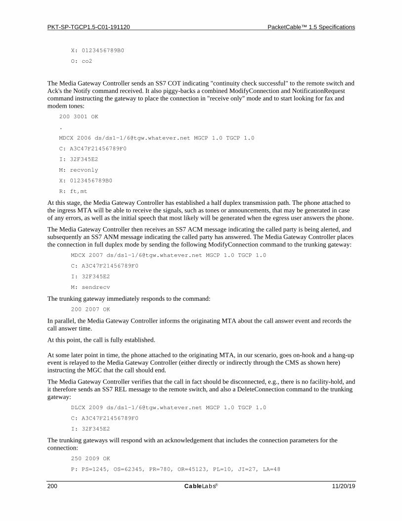
PKT-SP-TGCP1.5-C01-191120 PacketCable™ 1.5 Specifications
200 CableLabs 11/20/19
X: 0123456789B0
O: co2
The Media Gateway Controller sends an SS7 COT indicating "continuity check successful" to the remote switch and Ack's the Notify command received. It also piggy-backs a combined ModifyConnection and NotificationRequest command instructing the gateway to place the connection in "receive only" mode and to start looking for fax and modem tones:
200 3001 OK
.
MDCX 2006 ds/ds1-1/[email protected] MGCP 1.0 TGCP 1.0
C: A3C47F21456789F0
I: 32F345E2
M: recvonly
X: 0123456789B0
R: ft,mt
At this stage, the Media Gateway Controller has established a half duplex transmission path. The phone attached to the ingress MTA will be able to receive the signals, such as tones or announcements, that may be generated in case of any errors, as well as the initial speech that most likely will be generated when the egress user answers the phone.
The Media Gateway Controller then receives an SS7 ACM message indicating the called party is being alerted, and subsequently an SS7 ANM message indicating the called party has answered. The Media Gateway Controller places the connection in full duplex mode by sending the following ModifyConnection command to the trunking gateway:
MDCX 2007 ds/ds1-1/[email protected] MGCP 1.0 TGCP 1.0
C: A3C47F21456789F0
I: 32F345E2
M: sendrecv
The trunking gateway immediately responds to the command: 200 2007 OK
In parallel, the Media Gateway Controller informs the originating MTA about the call answer event and records the call answer time.
At this point, the call is fully established. At some later point in time, the phone attached to the originating MTA, in our scenario, goes on-hook and a hang-up event is relayed to the Media Gateway Controller (either directly or indirectly through the CMS as shown here) instructing the MGC that the call should end.
The Media Gateway Controller verifies that the call in fact should be disconnected, e.g., there is no facility-hold, and it therefore sends an SS7 REL message to the remote switch, and also a DeleteConnection command to the trunking gateway:
DLCX 2009 ds/ds1-1/[email protected] MGCP 1.0 TGCP 1.0
C: A3C47F21456789F0
I: 32F345E2
The trunking gateways will respond with an acknowledgement that includes the connection parameters for the connection:
250 2009 OK
P: PS=1245, OS=62345, PR=780, OR=45123, PL=10, JI=27, LA=48

PSTN Gateway Call Signaling Protocol Specification PKT-SP-TGCP1.5-C01-191120
11/20/19 CableLabs 201
A confirmation to the call tear-down in the form of an SS7 RLC message is also received by the Media Gateway Controller which finally records the end of the call.
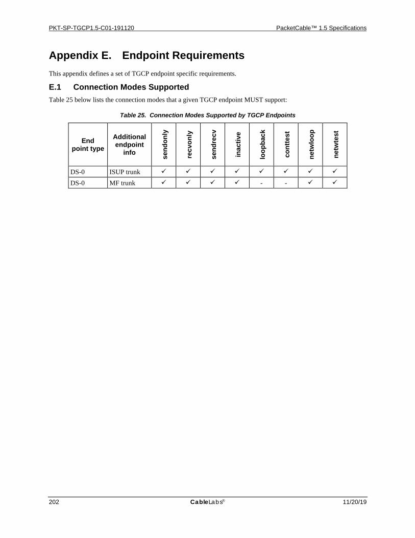
PKT-SP-TGCP1.5-C01-191120 PacketCable™ 1.5 Specifications
202 CableLabs 11/20/19
Appendix E. Endpoint Requirements This appendix defines a set of TGCP endpoint specific requirements.
E.1 Connection Modes Supported Table 25 below lists the connection modes that a given TGCP endpoint MUST support:
Table 25. Connection Modes Supported by TGCP Endpoints
End point type
Additional endpoint
info send
only
recv
only
send
recv
inac
tive
loop
back
cont
test
netw
loop
netw
test
DS-0 ISUP trunk
DS-0 MF trunk - -
PSTN Gateway Call Signaling Protocol Specification PKT-SP-TGCP1.5-C01-191120
11/20/19 CableLabs 203
Appendix F. Compatibility Information This appendix provides TGCP protocol compatibility information.
F.1 NCS Compatibility This version of TGCP is based on and aligned with NCS 1.5 [13] as much as possible. Since TGCP and NCS address different types of gateways a couple of differences do exist. The following summarizes these differences:
• Connection modes NCS and TGCP share a common set of connection modes, but each also has a set of connection modes the other does not support:
• NCS supports the connection modes "conference" and "replicate" which TGCP does not.
• TGCP supports the connection modes "continuity test" and "loopback" which NCS does not.
• Digit maps TGCP does not support digit maps, however NCS does. This has a couple of implications, e.g.,
• There is no TGCP command that can accept a digit map as a parameter.
• The "Accumulate according to digit map" action is not supported in TGCP.
• The "digit map" cannot be audited.
• Dynamic Quality of Service NCS supports PacketCable Dynamic of Quality of Service signaling, however TGCP does not.
In addition to the above, the following, non-protocol related, differences exist between NCS and TGCP. • Event packages The initial event packages in TGCP and NCS are different.
• Endpoint naming scheme The endpoint naming scheme for TGCP and NCS endpoints are slightly different.
F.2 MGCP Compatibility TGCP (and NCS) is furthermore a profile of MGCP 1.0 [1], however TGCP has introduced a couple of additions as well. The following lists TGCP additions that are currently not included in MGCP:
• Endpoint Naming Scheme A specific endpoint naming scheme has been introduced for DS-0 endpoints. The rules for wildcarding are more restrictive than in MGCP, and also introduces the "range" concept for DS-0 endpoints.
• Embedded ModifyConnection A new Embedded ModifyConnection action has been introduced.
• Security PacketCable Security services are supported in TGCP. This affects the LocalConnectionOptions, Capabilities, and SDP.
• Endpoint Name Retrieval The AuditEndpoint command has been extended with a capability to return the number of endpoints that match a wildcard as well as mechanism for block-wise retrieval of these endpoint names. Besides extending the AuditEndpoint command, this implies the introduction of two new parameter names; MaxEndPointIds, and NumEndPoints
• Supported Versions The RestartInProgress response and the AuditEndpoint command have been extended with a VersionSupported parameter to enable Media Gateway Controllers and gateways to determine which protocol versions each support.
• Error Codes Two new error codes have been introduced 532 and 533.
• Usage of SDP A new SDP usage profile is included in TGCP. Most notably, the profile and all example use specifically require strict SDP compliance, regardless of the usefulness of the included fields. Also, PacketCable specific extensions have been added to SDP.

PKT-SP-TGCP1.5-C01-191120 PacketCable™ 1.5 Specifications
204 CableLabs 11/20/19
• Provisional Response Additional detail and specification of the provisional response mechanism has been included in TGCP. A Response Acknowledgement response (000) has been introduced, an empty ResponseAck parameter has been permitted in final responses that follow provisional responses, and a procedure for the mechanism specified.
• Signal Parameters Signal parameter syntax has been extended to allow for the usage of balanced parenthesis within signal parameters. All Time-Out signals can have their time-out value altered by a signal parameter.
• Event Packages TGCP introduces a set of new event packages.
• Finally, it should be noted, that TGCP provides interpretations of and in some cases additional specification or clarification of the base MGCP protocol behavior that may or may not reflect the intended MGCP behavior.
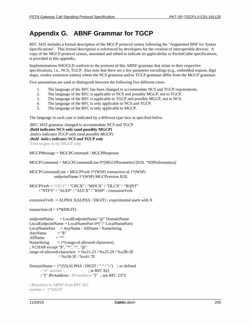
PSTN Gateway Call Signaling Protocol Specification PKT-SP-TGCP1.5-C01-191120
11/20/19 CableLabs 205
Appendix G. ABNF Grammar for TGCP RFC 3435 includes a formal description of the MGCP protocol syntax following the "Augmented BNF for Syntax Specifications". This formal description is referenced by developers for the creation of interoperable devices. A copy of the MGCP protocol syntax, annotated and edited to indicate its applicability to PacketCable specifications, is provided in this appendix.
Implementations SHOULD conform to the portions of this ABNF grammar that relate to their respective specifications, i.e., NCS, TGCP. Also note that there are a few parameter encodings (e.g., embedded request, digit maps, vendor extension names) where the NCS grammar and/or TGCP grammar differ from the MGCP grammar.
Five annotations are used to distinguish between the following five different cases:
1. The language of the RFC has been changed to accommodate NCS and TGCP requirements. 2. The language of the RFC is applicable to NCS and possibly MGCP, not to TGCP. 3. The language of the RFC is applicable to TGCP and possibly MGCP, not to NCS. 4. The language of the RFC is only applicable to NCS and TGCP. 5. The language of the RFC is only applicable to MGCP.
The language in each case is indicated by a different type face as specified below.
;RFC 3435 grammar changed to accommodate NCS and TGCP ;Bold indicates NCS only (and possibly MGCP) ;Italics indicates TGCP only (and possibly MGCP) ;Bold italics indicates NCS and TGCP only ;Text in grey is for MGCP only MGCPMessage = MGCPCommand / MGCPResponse MGCPCommand = MGCPCommandLine 0*(MGCPParameter) [EOL *SDPinformation] MGCPCommandLine = MGCPVerb 1*(WSP) transaction-id 1*(WSP) endpointName 1*(WSP) MGCPversion EOL MGCPVerb = "EPCF" / "CRCX" / "MDCX" / "DLCX" / "RQNT" / "NTFY" / "AUEP" / "AUCX" / "RSIP" / extensionVerb extensionVerb = ALPHA 3(ALPHA / DIGIT) ; experimental starts with X transaction-id = 1*9(DIGIT) endpointName = LocalEndpointName "@" DomainName LocalEndpointName = LocalNamePart 0*("/" LocalNamePart) LocalNamePart = AnyName / AllName / NameString AnyName = "$" AllName = "*" NameString = 1*(range-of-allowed-characters) ; VCHAR except "$", "*", "/", "@" range-of-allowed-characters = %x21-23 / %x25-29 / %x2B-2E / %x30-3F / %x41-7E DomainName = 1*255(ALPHA / DIGIT / "." / "-") ; as defined / "#" number ; in RFC 821 / "[" IPv4address / IPv6address "]" ; see RFC 2373 ; Rewritten to ABNF from RFC 821 number = 1*DIGIT
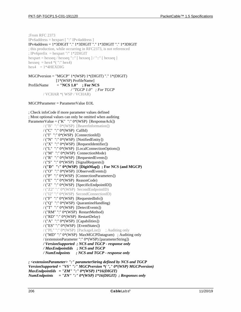
PKT-SP-TGCP1.5-C01-191120 PacketCable™ 1.5 Specifications
206 CableLabs 11/20/19
;From RFC 2373 IPv6address = hexpart [ ":" IPv4address ] IPv4address = 1*3DIGIT "." 1*3DIGIT "." 1*3DIGIT "." 1*3DIGIT ; this production, while occurring in RFC2373, is not referenced ; IPv6prefix = hexpart "/" 1*2DIGIT hexpart = hexseq / hexseq "::" [ hexseq ] / "::" [ hexseq ] hexseq = hex4 *( ":" hex4) hex4 = 1*4HEXDIG MGCPversion = "MGCP" 1*(WSP) 1*(DIGIT) "." 1*(DIGIT) [1*(WSP) ProfileName] ProfileName = "NCS 1.0" ; For NCS / "TGCP 1.0" ; For TGCP / VCHAR *( WSP / VCHAR) MGCPParameter = ParameterValue EOL ; Check infoCode if more parameter values defined ; Most optional values can only be omitted when auditing ParameterValue = ("K" ":" 0*(WSP) [ResponseAck]) / ("B" ":" 0*(WSP) [BearerInformation]) / ("C" ":" 0*(WSP) CallId) / ("I" ":" 0*(WSP) [ConnectionId]) / ("N" ":" 0*(WSP) [NotifiedEntity]) / ("X" ":" 0*(WSP) [RequestIdentifier]) / ("L" ":" 0*(WSP) [LocalConnectionOptions]) / ("M" ":" 0*(WSP) ConnectionMode) / ("R" ":" 0*(WSP) [RequestedEvents]) / ("S" ":" 0*(WSP) [SignalRequests]) / ("D" ":" 0*(WSP) [DigitMap]) ; For NCS (and MGCP) / ("O" ":" 0*(WSP) [ObservedEvents]) / ("P" ":" 0*(WSP) [ConnectionParameters]) / ("E" ":" 0*(WSP) ReasonCode) / ("Z" ":" 0*(WSP) [SpecificEndpointID]) / ("Z2" ":" 0*(WSP) SecondEndpointID) / ("I2" ":" 0*(WSP) SecondConnectionID) / ("F" ":" 0*(WSP) [RequestedInfo]) / ("Q" ":" 0*(WSP) QuarantineHandling) / ("T" ":" 0*(WSP) [DetectEvents]) / ("RM" ":" 0*(WSP) RestartMethod) / ("RD" ":" 0*(WSP) RestartDelay) / ("A" ":" 0*(WSP) [Capabilities]) / ("ES" ":" 0*(WSP) [EventStates]) / ("PL" ":" 0*(WSP) [PackageList]) ; Auditing only / ("MD" ":" 0*(WSP) MaxMGCPDatagram) ; Auditing only / (extensionParameter ":" 0*(WSP) [parameterString]) / VersionSupported ; NCS and TGCP - response only / MaxEndpointIds ; NCS and TGCP / NumEndpoints ; NCS and TGCP - response only ; <extensionParameter> ":" parameterString defined by NCS and TGCP VersionSupported = "VS" ":" MGCPversion *( "," 0*(WSP) MGCPversion) MaxEndpointIds = "ZM" ":" 0*(WSP) 1*16(DIGIT) NumEndpoints = "ZN" ":" 0*(WSP) 1*16(DIGIT) ; Responses only
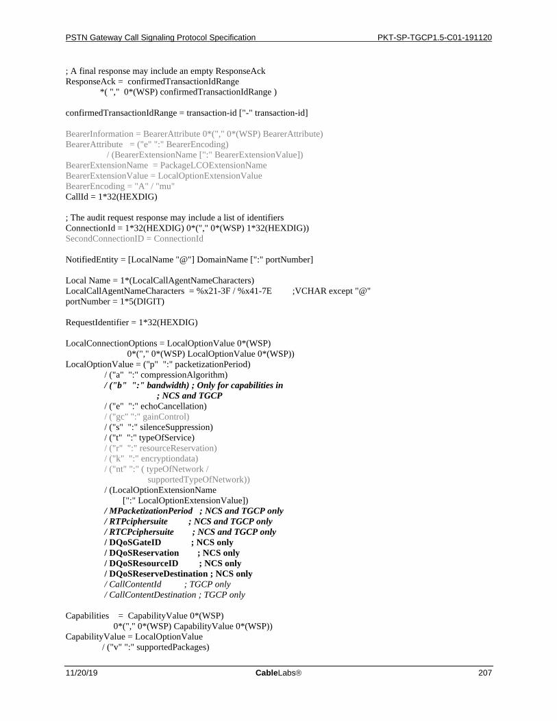
PSTN Gateway Call Signaling Protocol Specification PKT-SP-TGCP1.5-C01-191120
11/20/19 CableLabs 207
; A final response may include an empty ResponseAck ResponseAck = confirmedTransactionIdRange *( "," 0*(WSP) confirmedTransactionIdRange ) confirmedTransactionIdRange = transaction-id ["-" transaction-id] BearerInformation = BearerAttribute 0*("," 0*(WSP) BearerAttribute) BearerAttribute = ("e" ":" BearerEncoding) / (BearerExtensionName [":" BearerExtensionValue]) BearerExtensionName = PackageLCOExtensionName BearerExtensionValue = LocalOptionExtensionValue BearerEncoding = "A" / "mu" CallId = 1*32(HEXDIG) ; The audit request response may include a list of identifiers ConnectionId = 1*32(HEXDIG) 0*("," 0*(WSP) 1*32(HEXDIG)) SecondConnectionID = ConnectionId NotifiedEntity = [LocalName "@"] DomainName [":" portNumber] Local Name = 1*(LocalCallAgentNameCharacters) LocalCallAgentNameCharacters = %x21-3F / %x41-7E ;VCHAR except "@" portNumber = 1*5(DIGIT) RequestIdentifier = 1*32(HEXDIG) LocalConnectionOptions = LocalOptionValue 0*(WSP) 0*("," 0*(WSP) LocalOptionValue 0*(WSP)) LocalOptionValue = ("p" ":" packetizationPeriod) / ("a" ":" compressionAlgorithm) / ("b" ":" bandwidth) ; Only for capabilities in ; NCS and TGCP / ("e" ":" echoCancellation) / ("gc" ":" gainControl) / ("s" ":" silenceSuppression) / ("t" ":" typeOfService) / ("r" ":" resourceReservation) / ("k" ":" encryptiondata) / ("nt" ":" ( typeOfNetwork / supportedTypeOfNetwork)) / (LocalOptionExtensionName [":" LocalOptionExtensionValue]) / MPacketizationPeriod ; NCS and TGCP only / RTPciphersuite ; NCS and TGCP only / RTCPciphersuite ; NCS and TGCP only / DQoSGateID ; NCS only / DQoSReservation ; NCS only / DQoSResourceID ; NCS only / DQoSReserveDestination ; NCS only / CallContentId ; TGCP only / CallContentDestination ; TGCP only Capabilities = CapabilityValue 0*(WSP) 0*("," 0*(WSP) CapabilityValue 0*(WSP)) CapabilityValue = LocalOptionValue / ("v" ":" supportedPackages)
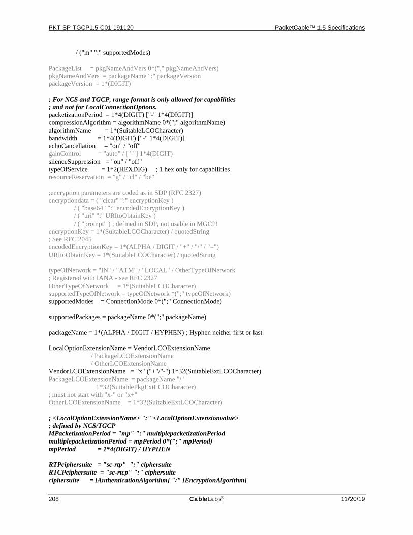
PKT-SP-TGCP1.5-C01-191120 PacketCable™ 1.5 Specifications
208 CableLabs 11/20/19
/ ("m" ":" supportedModes) PackageList = pkgNameAndVers 0*("," pkgNameAndVers) pkgNameAndVers = packageName ":" packageVersion packageVersion = 1*(DIGIT) ; For NCS and TGCP, range format is only allowed for capabilities ; and not for LocalConnectionOptions. packetizationPeriod = 1*4(DIGIT) ["-" 1*4(DIGIT)] compressionAlgorithm = algorithmName 0*(";" algorithmName) algorithmName = 1*(SuitableLCOCharacter) bandwidth = 1*4(DIGIT) ["-" 1*4(DIGIT)] echoCancellation = "on" / "off" gainControl = "auto" / ["-"] 1*4(DIGIT) silenceSuppression = "on" / "off" typeOfService = 1*2(HEXDIG) ; 1 hex only for capabilities resourceReservation = "g" / "cl" / "be" ;encryption parameters are coded as in SDP (RFC 2327) encryptiondata = ( "clear" ":" encryptionKey ) / ( "base64" ":" encodedEncryptionKey ) / ( "uri" ":" URItoObtainKey ) / ( "prompt" ) ; defined in SDP, not usable in MGCP! encryptionKey = 1*(SuitableLCOCharacter) / quotedString ; See RFC 2045 encodedEncryptionKey = 1*(ALPHA / DIGIT / "+" / "/" / "=") URItoObtainKey = 1*(SuitableLCOCharacter) / quotedString typeOfNetwork = "IN" / "ATM" / "LOCAL" / OtherTypeOfNetwork ; Registered with IANA - see RFC 2327 OtherTypeOfNetwork = 1*(SuitableLCOCharacter) supportedTypeOfNetwork = typeOfNetwork *(";" typeOfNetwork) supportedModes = ConnectionMode 0*(";" ConnectionMode) supportedPackages = packageName 0*(";" packageName) packageName = 1*(ALPHA / DIGIT / HYPHEN) ; Hyphen neither first or last LocalOptionExtensionName = VendorLCOExtensionName / PackageLCOExtensionName / OtherLCOExtensionName VendorLCOExtensionName = "x" ("+"/"-") 1*32(SuitableExtLCOCharacter) PackageLCOExtensionName = packageName "/" 1*32(SuitablePkgExtLCOCharacter) ; must not start with "x-" or "x+" OtherLCOExtensionName = 1*32(SuitableExtLCOCharacter) ; <LocalOptionExtensionName> ":" <LocalOptionExtensionvalue> ; defined by NCS/TGCP MPacketizationPeriod = "mp" ":" multiplepacketizationPeriod multiplepacketizationPeriod = mpPeriod 0*(";" mpPeriod) mpPeriod = 1*4(DIGIT) / HYPHEN RTPciphersuite = "sc-rtp" ":" ciphersuite RTCPciphersuite = "sc-rtcp" ":" ciphersuite ciphersuite = [AuthenticationAlgorithm] "/" [EncryptionAlgorithm]
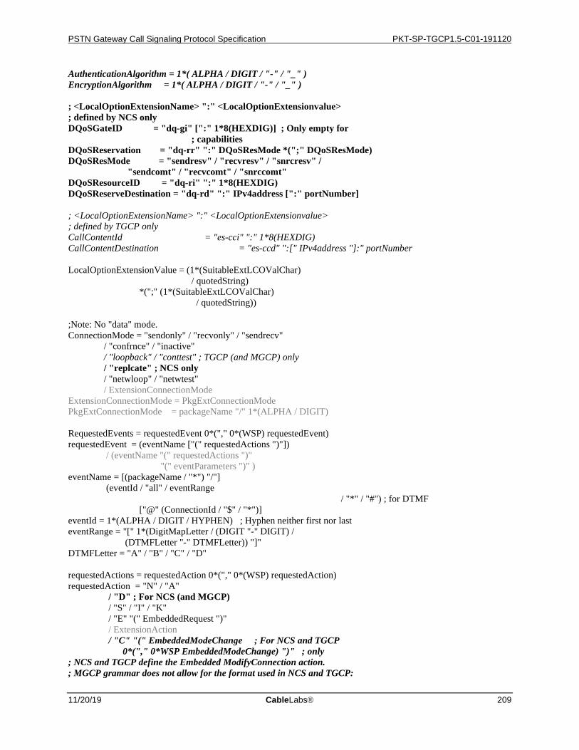
PSTN Gateway Call Signaling Protocol Specification PKT-SP-TGCP1.5-C01-191120
11/20/19 CableLabs 209
AuthenticationAlgorithm = 1*( ALPHA / DIGIT / "-" / "_" ) EncryptionAlgorithm = 1*( ALPHA / DIGIT / "-" / "_" ) ; <LocalOptionExtensionName> ":" <LocalOptionExtensionvalue> ; defined by NCS only DQoSGateID = "dq-gi" [":" 1*8(HEXDIG)] ; Only empty for ; capabilities DQoSReservation = "dq-rr" ":" DQoSResMode *(";" DQoSResMode) DQoSResMode = "sendresv" / "recvresv" / "snrcresv" / "sendcomt" / "recvcomt" / "snrccomt" DQoSResourceID = "dq-ri" ":" 1*8(HEXDIG) DQoSReserveDestination = "dq-rd" ":" IPv4address [":" portNumber] ; <LocalOptionExtensionName> ":" <LocalOptionExtensionvalue> ; defined by TGCP only CallContentId = "es-cci" ":" 1*8(HEXDIG) CallContentDestination = "es-ccd" ":[" IPv4address "]:" portNumber LocalOptionExtensionValue = (1*(SuitableExtLCOValChar) / quotedString) *(";" (1*(SuitableExtLCOValChar) / quotedString)) ;Note: No "data" mode. ConnectionMode = "sendonly" / "recvonly" / "sendrecv" / "confrnce" / "inactive" / "loopback" / "conttest" ; TGCP (and MGCP) only / "replcate" ; NCS only / "netwloop" / "netwtest" / ExtensionConnectionMode ExtensionConnectionMode = PkgExtConnectionMode PkgExtConnectionMode = packageName "/" 1*(ALPHA / DIGIT) RequestedEvents = requestedEvent 0*("," 0*(WSP) requestedEvent) requestedEvent = (eventName ["(" requestedActions ")"]) / (eventName "(" requestedActions ")" "(" eventParameters ")" ) eventName = [(packageName / "*") "/"] (eventId / "all" / eventRange / "*" / "#") ; for DTMF ["@" (ConnectionId / "$" / "*")] eventId = 1*(ALPHA / DIGIT / HYPHEN) ; Hyphen neither first nor last eventRange = "[" 1*(DigitMapLetter / (DIGIT "-" DIGIT) / (DTMFLetter "-" DTMFLetter)) "]" DTMFLetter = "A" / "B" / "C" / "D" requestedActions = requestedAction 0*("," 0*(WSP) requestedAction) requestedAction = "N" / "A" / "D" ; For NCS (and MGCP) / "S" / "I" / "K" / "E" "(" EmbeddedRequest ")" / ExtensionAction / "C" "(" EmbeddedModeChange ; For NCS and TGCP 0*("," 0*WSP EmbeddedModeChange) ")" ; only ; NCS and TGCP define the Embedded ModifyConnection action. ; MGCP grammar does not allow for the format used in NCS and TGCP:
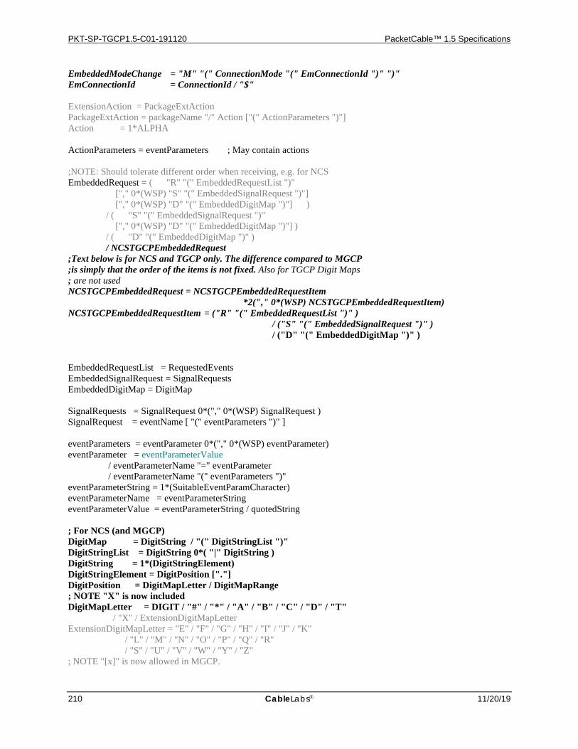
PKT-SP-TGCP1.5-C01-191120 PacketCable™ 1.5 Specifications
210 CableLabs 11/20/19
EmbeddedModeChange = "M" "(" ConnectionMode "(" EmConnectionId ")" ")" EmConnectionId = ConnectionId / "$"
ExtensionAction = PackageExtAction PackageExtAction = packageName "/" Action ["(" ActionParameters ")"] Action = 1*ALPHA ActionParameters = eventParameters ; May contain actions ;NOTE: Should tolerate different order when receiving, e.g. for NCS EmbeddedRequest = ( "R" "(" EmbeddedRequestList ")" ["," 0*(WSP) "S" "(" EmbeddedSignalRequest ")"] ["," 0*(WSP) "D" "(" EmbeddedDigitMap ")"] ) / ( "S" "(" EmbeddedSignalRequest ")" ["," 0*(WSP) "D" "(" EmbeddedDigitMap ")"] ) / ( "D" "(" EmbeddedDigitMap ")" ) / NCSTGCPEmbeddedRequest ;Text below is for NCS and TGCP only. The difference compared to MGCP ;is simply that the order of the items is not fixed. Also for TGCP Digit Maps ; are not used NCSTGCPEmbeddedRequest = NCSTGCPEmbeddedRequestItem *2("," 0*(WSP) NCSTGCPEmbeddedRequestItem) NCSTGCPEmbeddedRequestItem = ("R" "(" EmbeddedRequestList ")" ) / ("S" "(" EmbeddedSignalRequest ")" ) / ("D" "(" EmbeddedDigitMap ")" ) EmbeddedRequestList = RequestedEvents EmbeddedSignalRequest = SignalRequests EmbeddedDigitMap = DigitMap SignalRequests = SignalRequest 0*("," 0*(WSP) SignalRequest ) SignalRequest = eventName [ "(" eventParameters ")" ] eventParameters = eventParameter 0*("," 0*(WSP) eventParameter) eventParameter = eventParameterValue / eventParameterName "=" eventParameter / eventParameterName "(" eventParameters ")" eventParameterString = 1*(SuitableEventParamCharacter) eventParameterName = eventParameterString eventParameterValue = eventParameterString / quotedString ; For NCS (and MGCP) DigitMap = DigitString / "(" DigitStringList ")" DigitStringList = DigitString 0*( "|" DigitString ) DigitString = 1*(DigitStringElement) DigitStringElement = DigitPosition ["."] DigitPosition = DigitMapLetter / DigitMapRange ; NOTE "X" is now included DigitMapLetter = DIGIT / "#" / "*" / "A" / "B" / "C" / "D" / "T" / "X" / ExtensionDigitMapLetter ExtensionDigitMapLetter = "E" / "F" / "G" / "H" / "I" / "J" / "K" / "L" / "M" / "N" / "O" / "P" / "Q" / "R" / "S" / "U" / "V" / "W" / "Y" / "Z" ; NOTE "[x]" is now allowed in MGCP.
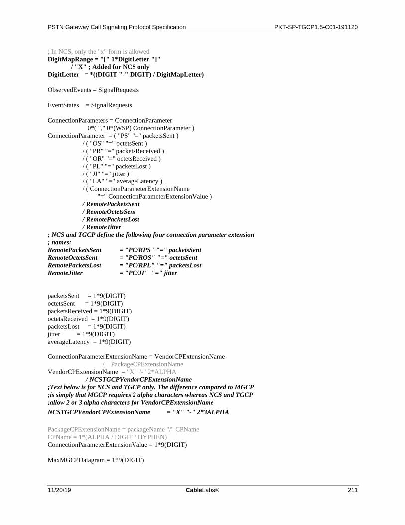
PSTN Gateway Call Signaling Protocol Specification PKT-SP-TGCP1.5-C01-191120
11/20/19 CableLabs 211
; In NCS, only the "x" form is allowed DigitMapRange = "[" 1*DigitLetter "]" / "X" ; Added for NCS only DigitLetter = *((DIGIT "-" DIGIT) / DigitMapLetter) ObservedEvents = SignalRequests EventStates = SignalRequests ConnectionParameters = ConnectionParameter 0*( "," 0*(WSP) ConnectionParameter ) ConnectionParameter = ( "PS" "=" packetsSent ) / ( "OS" "=" octetsSent ) / ( "PR" "=" packetsReceived ) / ( "OR" "=" octetsReceived ) / ( "PL" "=" packetsLost ) / ( "JI" "=" jitter ) / ( "LA" "=" averageLatency ) / ( ConnectionParameterExtensionName "=" ConnectionParameterExtensionValue ) / RemotePacketsSent / RemoteOctetsSent / RemotePacketsLost / RemoteJitter ; NCS and TGCP define the following four connection parameter extension ; names: RemotePacketsSent = "PC/RPS" "=" packetsSent RemoteOctetsSent = "PC/ROS" "=" octetsSent RemotePacketsLost = "PC/RPL" "=" packetsLost RemoteJitter = "PC/JI" "=" jitter packetsSent = 1*9(DIGIT) octetsSent = 1*9(DIGIT) packetsReceived = 1*9(DIGIT) octetsReceived = 1*9(DIGIT) packetsLost = 1*9(DIGIT) jitter = 1*9(DIGIT) averageLatency = 1*9(DIGIT) ConnectionParameterExtensionName = VendorCPExtensionName / PackageCPExtensionName VendorCPExtensionName = "X" "-" 2*ALPHA / NCSTGCPVendorCPExtensionName ;Text below is for NCS and TGCP only. The difference compared to MGCP ;is simply that MGCP requires 2 alpha characters whereas NCS and TGCP ;allow 2 or 3 alpha characters for VendorCPExtensionName NCSTGCPVendorCPExtensionName = "X" "-" 2*3ALPHA PackageCPExtensionName = packageName "/" CPName CPName = 1*(ALPHA / DIGIT / HYPHEN) ConnectionParameterExtensionValue = 1*9(DIGIT) MaxMGCPDatagram = 1*9(DIGIT)

PKT-SP-TGCP1.5-C01-191120 PacketCable™ 1.5 Specifications
212 CableLabs 11/20/19
ReasonCode = 3DIGIT [1*(WSP) "/" packageName] ; Only for 8xx [WSP 1*(%x20-7E)] SpecificEndpointID = endpointName SecondEndpointID = endpointName RequestedInfo = infoCode 0*("," 0*(WSP) infoCode) infoCode = "B" / "C" / "I" / "N" / "X" / "L" / "M" / "R" / "S" / "D" ; For NCS (and MGCP) only
/ "O" / "P" / "E" / "Z" / "Q" / "T" / "RC" / "LC" / "A" / "ES" / "RM" / "RD" / "PL" / "MD" / extensionParameter
/ "VS" / "ZM" / "ZN" ; NCS and TGCP define these ; three extensionParameters ;NCS and TGCP allows for process and loop control in either order QuarantineHandling = loopControl / processControl / (loopControl "," 0*(WSP) processControl ) / (processControl "," 0*(WSP) loopControl) loopControl = "step" / "loop" processControl = "process" / "discard" DetectEvents = SignalRequests RestartMethod = "graceful" / "forced" / "restart" / "disconnected" / "cancel-graceful" / extensionRestartMethod extensionRestartMethod = PackageExtensionRM PackageExtensionRM = packageName "/" 1*32(ALPHA / DIGIT / HYPHEN) RestartDelay = 1*6(DIGIT) extensionParameter = VendorExtensionParameter / PackageExtensionParameter / OtherExtensionParameter VendorExtensionParameter = "X" ("-"/"+") 1*6(ALPHA / DIGIT) PackageExtensionParameter = packageName "/" 1*32(ALPHA / DIGIT / HYPHEN) ; must not start with "x-" or x+" OtherExtensionParameter = 1*32(ALPHA / DIGIT / HYPHEN) ;If first character is a double-quote, then it is a quoted-string parameterString = (%x21 / %x23-7F) *(%x20-7F) ; first and last must not ; be white space / quotedString MGCPResponse = MGCPResponseLine 0*(MGCPParameter) *2(EOL *SDPinformation) MGCPResponseLine = responseCode 1*(WSP) transaction-id [1*(WSP) "/" packageName] ; Only for 8xx [WSP responseString] EOL responseCode = 3DIGIT responseString = *(%x20-7E) SuitablePkgExtLCOCharacter = SuitableLCOCharacter

PSTN Gateway Call Signaling Protocol Specification PKT-SP-TGCP1.5-C01-191120
11/20/19 CableLabs 213
SuitableExtLCOCharacter = DIGIT / ALPHA / "+" / "-" / "_" / "&" / "!" / "'" / "|" / "=" / "#" / "?" / "." / "$" / "*" / "@" / "[" / "]" / "^" / "`" / "{" / "}" / "~"
SuitableLCOCharacter = SuitableExtLCOCharacter / "/" SuitableExtLCOValChar = SuitableLCOCharacter / ":" ; VCHAR except """, "(", ")", ",", and "=" SuitableEventParamCharacter = %x21 / %x23-27 / %x2A-2B / %x2D-3C / %x3E-7E ; NOTE: UTF8 encoded quotedString = DQUOTE 0*(quoteEscape / quoteChar) DQUOTE quoteEscape = DQUOTE DQUOTE quoteChar = (%x00-21 / %x23-FF) EOL = CRLF / LF HYPHEN = "-" ; See RFC 2327 for proper SDP grammar instead. SDPinformation = SDPLine CRLF *(SDPLine CRLF) ; see RFC 2327 SDPLine = 1*(%x01-09 / %x0B / %x0C / %x0E-FF) ; for proper def.
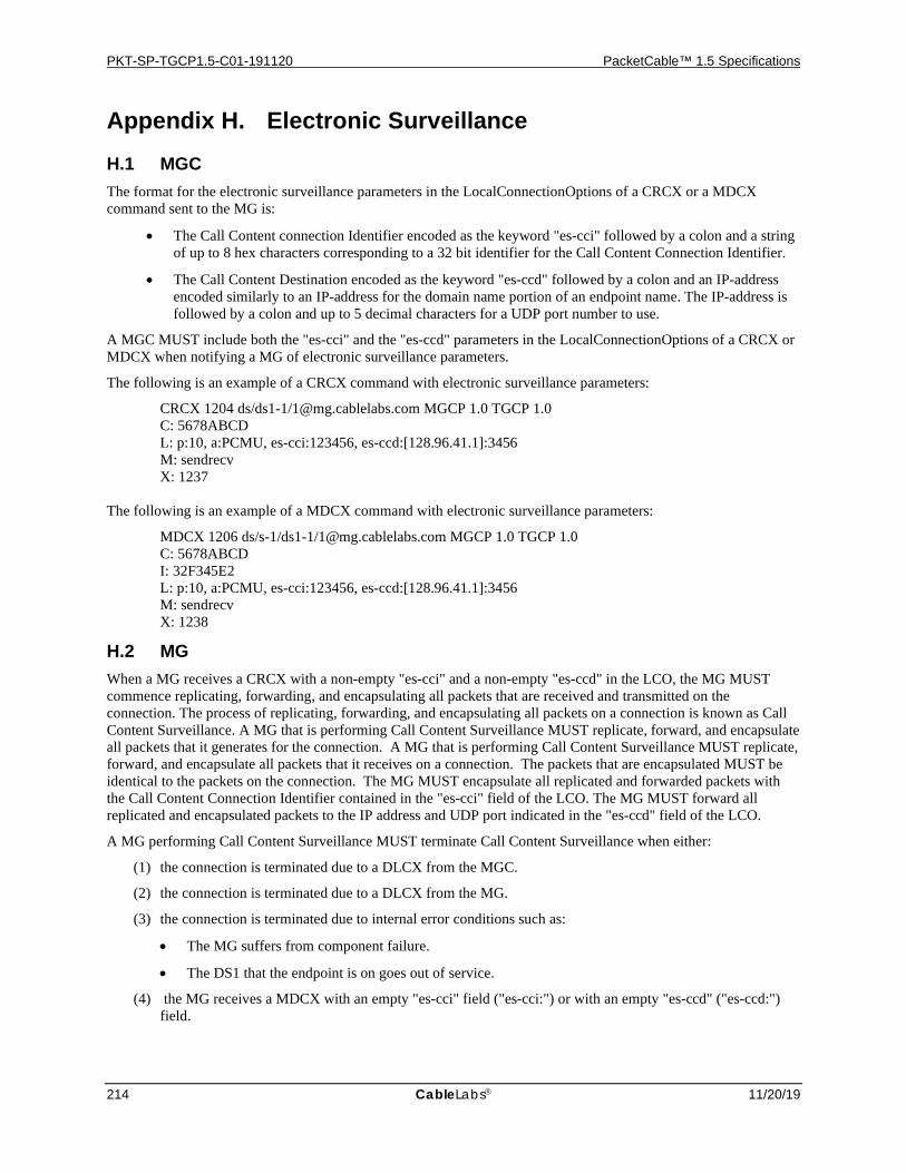
PKT-SP-TGCP1.5-C01-191120 PacketCable™ 1.5 Specifications
214 CableLabs 11/20/19
Appendix H. Electronic Surveillance H.1 MGC The format for the electronic surveillance parameters in the LocalConnectionOptions of a CRCX or a MDCX command sent to the MG is:
• The Call Content connection Identifier encoded as the keyword "es-cci" followed by a colon and a string of up to 8 hex characters corresponding to a 32 bit identifier for the Call Content Connection Identifier.
• The Call Content Destination encoded as the keyword "es-ccd" followed by a colon and an IP-address encoded similarly to an IP-address for the domain name portion of an endpoint name. The IP-address is followed by a colon and up to 5 decimal characters for a UDP port number to use.
A MGC MUST include both the "es-cci" and the "es-ccd" parameters in the LocalConnectionOptions of a CRCX or MDCX when notifying a MG of electronic surveillance parameters.
The following is an example of a CRCX command with electronic surveillance parameters:
CRCX 1204 ds/ds1-1/[email protected] MGCP 1.0 TGCP 1.0 C: 5678ABCD L: p:10, a:PCMU, es-cci:123456, es-ccd:[128.96.41.1]:3456 M: sendrecv
X: 1237 The following is an example of a MDCX command with electronic surveillance parameters:
MDCX 1206 ds/s-1/ds1-1/[email protected] MGCP 1.0 TGCP 1.0 C: 5678ABCD I: 32F345E2 L: p:10, a:PCMU, es-cci:123456, es-ccd:[128.96.41.1]:3456 M: sendrecv X: 1238
H.2 MG When a MG receives a CRCX with a non-empty "es-cci" and a non-empty "es-ccd" in the LCO, the MG MUST commence replicating, forwarding, and encapsulating all packets that are received and transmitted on the connection. The process of replicating, forwarding, and encapsulating all packets on a connection is known as Call Content Surveillance. A MG that is performing Call Content Surveillance MUST replicate, forward, and encapsulate all packets that it generates for the connection. A MG that is performing Call Content Surveillance MUST replicate, forward, and encapsulate all packets that it receives on a connection. The packets that are encapsulated MUST be identical to the packets on the connection. The MG MUST encapsulate all replicated and forwarded packets with the Call Content Connection Identifier contained in the "es-cci" field of the LCO. The MG MUST forward all replicated and encapsulated packets to the IP address and UDP port indicated in the "es-ccd" field of the LCO.
A MG performing Call Content Surveillance MUST terminate Call Content Surveillance when either:
(1) the connection is terminated due to a DLCX from the MGC.
(2) the connection is terminated due to a DLCX from the MG.
(3) the connection is terminated due to internal error conditions such as:
• The MG suffers from component failure.
• The DS1 that the endpoint is on goes out of service.
(4) the MG receives a MDCX with an empty "es-cci" field ("es-cci:") or with an empty "es-ccd" ("es-ccd:") field.
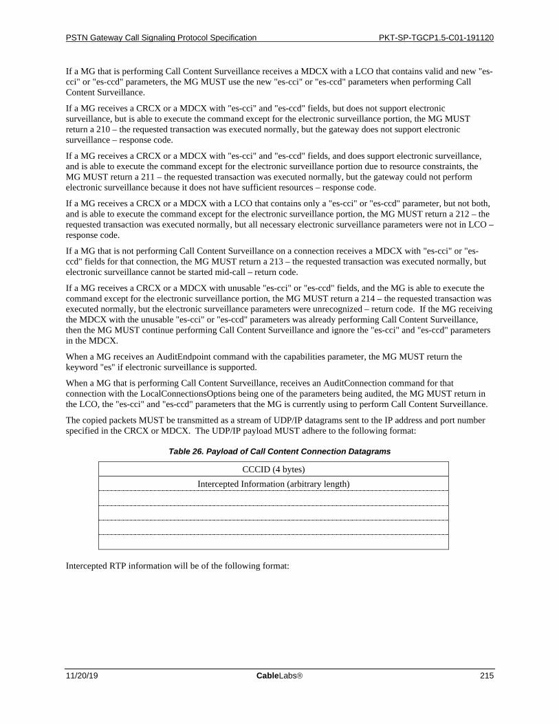
PSTN Gateway Call Signaling Protocol Specification PKT-SP-TGCP1.5-C01-191120
11/20/19 CableLabs 215
If a MG that is performing Call Content Surveillance receives a MDCX with a LCO that contains valid and new "es-cci" or "es-ccd" parameters, the MG MUST use the new "es-cci" or "es-ccd" parameters when performing Call Content Surveillance.
If a MG receives a CRCX or a MDCX with "es-cci" and "es-ccd" fields, but does not support electronic surveillance, but is able to execute the command except for the electronic surveillance portion, the MG MUST return a 210 – the requested transaction was executed normally, but the gateway does not support electronic surveillance – response code.
If a MG receives a CRCX or a MDCX with "es-cci" and "es-ccd" fields, and does support electronic surveillance, and is able to execute the command except for the electronic surveillance portion due to resource constraints, the MG MUST return a 211 – the requested transaction was executed normally, but the gateway could not perform electronic surveillance because it does not have sufficient resources – response code.
If a MG receives a CRCX or a MDCX with a LCO that contains only a "es-cci" or "es-ccd" parameter, but not both, and is able to execute the command except for the electronic surveillance portion, the MG MUST return a 212 – the requested transaction was executed normally, but all necessary electronic surveillance parameters were not in LCO – response code.
If a MG that is not performing Call Content Surveillance on a connection receives a MDCX with "es-cci" or "es-ccd" fields for that connection, the MG MUST return a 213 – the requested transaction was executed normally, but electronic surveillance cannot be started mid-call – return code.
If a MG receives a CRCX or a MDCX with unusable "es-cci" or "es-ccd" fields, and the MG is able to execute the command except for the electronic surveillance portion, the MG MUST return a 214 – the requested transaction was executed normally, but the electronic surveillance parameters were unrecognized – return code. If the MG receiving the MDCX with the unusable "es-cci" or "es-ccd" parameters was already performing Call Content Surveillance, then the MG MUST continue performing Call Content Surveillance and ignore the "es-cci" and "es-ccd" parameters in the MDCX.
When a MG receives an AuditEndpoint command with the capabilities parameter, the MG MUST return the keyword "es" if electronic surveillance is supported.
When a MG that is performing Call Content Surveillance, receives an AuditConnection command for that connection with the LocalConnectionsOptions being one of the parameters being audited, the MG MUST return in the LCO, the "es-cci" and "es-ccd" parameters that the MG is currently using to perform Call Content Surveillance.
The copied packets MUST be transmitted as a stream of UDP/IP datagrams sent to the IP address and port number specified in the CRCX or MDCX. The UDP/IP payload MUST adhere to the following format:
Table 26. Payload of Call Content Connection Datagrams
CCCID (4 bytes) Intercepted Information (arbitrary length)
Intercepted RTP information will be of the following format:
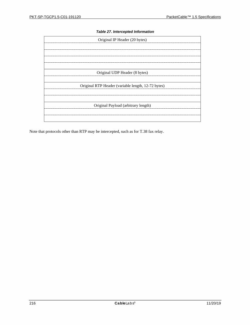
PKT-SP-TGCP1.5-C01-191120 PacketCable™ 1.5 Specifications
216 CableLabs 11/20/19
Table 27. Intercepted Information
Original IP Header (20 bytes)
Original UDP Header (8 bytes)
Original RTP Header (variable length, 12-72 bytes)
Original Payload (arbitrary length)
Note that protocols other than RTP may be intercepted, such as for T.38 fax relay.

PSTN Gateway Call Signaling Protocol Specification PKT-SP-TGCP1.5-C01-191120
11/20/19 CableLabs 217
Appendix I. Acknowledgements This specification was developed and influenced by numerous individuals representing many different vendors and organizations. PacketCable hereby wishes to thank everybody who participated directly or indirectly in this effort. In particular, PacketCable wants to recognize the authors of the original SGCP, MGCP, IPDC, and NCS specifications for the work they have done. Furthermore, PacketCable wishes to thank the following individuals for their involvement and contributions to this specification:
Flemming Andreasen/Telcordia (primary author)
Bill Foster/Cisco
Keith Kelly/Netspeak
Don Stanwyck/Lucent
Ed Miller/CableLabs
Kevin Johns/Telcordia
Brian Williams/General Bandwidth
Anthony Anconetani/General Bandwidth
Jason Byrne/Nuera
Arthur Mistler/Siemens
David McIntosh/CableLabs
Jean-Francois Mule/CableLabs
David Hancock/CableLabs
Sandeep Sharma/CableLabs
Joey Padden, CableLabs

PKT-SP-TGCP1.5-C01-191120 PacketCable™ 1.5 Specifications
218 CableLabs 11/20/19
Appendix J. Revision History The following ECN was included in TGCP1.5- I02-050812.
ECN ECN Date Summary TGCP1.5-N-05.0226-5 3/14/05 Media security parameter usage for T38
The following ECNs were included in TGCP1.5-I03-070412.
ECN ECN Date Summary TGCP1.5-N-05.0303-3 3/27/06 V.152 Support TGCP1.5-N-07.0386-3 2/26/07 Make the support for packages related to V.152 optional in TGCP TGCP1.5-N-07.0404-3 3/12/07 Fix errors in ECN TGCP1.5-N-05.0303-3. TGCP1.5-N-07.0406-5 3/19/07 Update and correct references in TGCP TGCP1.5-N-07.0410-3 3/12/07 Allow inclusion of T.38MaxBitRate attribute in negotiation of T.38
fax The following ECN was included in TGCP1.5-I04-120412.
ECN ECN Date Summary TGCP1.5-N-11.0668-2 2/13/12 TGCP reference to CODEC corrections