Embed Size (px)
Citation preview

PAGE 1
Transition Networks, Inc.Worldwide Headquarters:10900 Red Circle DriveMinnetonka, MN 55343 USA
tel: 952.941.7600 / 800.526.9267fax: [email protected]://www.transition.com
©2011 Transition Networks, Inc.All trade marks are the property of their respective owners.Technical information is subject to change without notice.
PacketBand-V.35/X.21Technical Specification
Deliver clock-locked X.21 and V.35 circuits over Ethernet, IP or MPLS networks,including wireless networks. Designed for synchronous services that require locked clocks; a “leased line” over packet networks.
Support for copper (UTP) and fibre (SFP) networks and for LACP and RSTP.
The PacketBand-V.35/X.21 provides reliable, transparent and manageable end-to-end X.21 and V.35 connectivity across packet networks. It can connect to local devices and/or leased lines and is able to provide, take and recover clocks.
Circuits can be established 24/7 or in response to requests from the attached equipment via control signals so the circuit is established periodically and on demand.
PacketBand also supports Multicast for simplex broadcast applications.
Clocks are recovered extremely accurately and can exceed the G.823 Synchronous Interface requirement which is used extensively as the quality guide-line for leased lines.
1. Connectivity Overview PacketBand-V.35/X.21 supplies a clear or transparent serial clock-recovered or synchronous “pipe” at speeds to 2.048Mbps across different types of packet networks. It duplicates a traditionally-delivered X.21 or V.35 carrier leased line but uses low-cost and widely available packet networks as the transport medium.
Clocks can be generated from one PacketBand and recovered by the other, ensuring Synchronization and no data slips. The onboard oscillators are very accurate, the standard being Stratum3 with enhanced versions available.
This configuration provides synchronized clocks to both ends of the circuit when there is no available clock source at the customer premises. This is a common situation when replacing X.21 and V.35 leased lines as these will have normally provided clock from the carrier’s local exchange.
PacketBand can also source clocks in these instances from a centrally located Multicast source (see section 3).
Or clock can be supplied by the CPE/DTE or leased line
Or similar clocks from two leased lines can be accepted, in effect
X.21 V.35
X.21 V.35Packet Network
Recovered Clock
Clock "Slave"
Clock "Master"
X.21 V.35
X.21 V.35Packet Network
Recovered Clock
Clock from local deviceor leased line.
CSU / DSUNTU
Packet Network
Clock from localdevice or leased line.
CSU / DSUNTU
Clock from local deviceor leased line.
CSU / DSUNTU
Packet Network

PAGE 2
Transition Networks, Inc.Worldwide Headquarters:10900 Red Circle DriveMinnetonka, MN 55343 USA
tel: 952.941.7600 / 800.526.9267fax: [email protected]://www.transition.com
©2011 Transition Networks, Inc.All trade marks are the property of their respective owners.Technical information is subject to change without notice.
2. Control Signal Dialling The PacketBand delivers a circuit 24/7 but optionally also has the ability to establish the link in response to a DTE raising a control lead.
In an X.21 interface for example, a DTE raising “C” will initiate the PacketBand to establish a pre-configured link to a remote location, presenting the “I” lead to both ends of the link when the circuit is established. Control signals are presented and coordinated at both ends of the circuit.
This feature means network capacity is only used when required by the DTE application.
3. Multicast PacketBand has the unique feature of supporting Multicast transmission which has three key advantages.
3.1 Multicast is an efficient method of transporting unidirectional (simplex) traffic from one main transmission location to multiple remote sites. PacketBand has the ability to transmit to a Multicast-enabled router and for remote PacketBands to “join” Multicast groups.
This optional facility, together with the PacketBand’s excellent clock recovery accuracy, makes the system ideal for broadcast applications.
3.2 The Multicast capability also means that the PacketBand can separate the clock recovery data from the bulk user data. This means larger networks with multiple “hops” can deliver not only improved clock Synchronization, but there are network design/loading/QoS and resiliency benefits as well.
3.3 X.21 and V.35 leased lines are normally provided with the clock coming from the carrier network. The Multicast feature means all customer sites can be easily synchronized, particually where no clock source is available at the end user site.
When delivering clocked services to customer sites the Multicast feature ensures all customer sites are clock-locked/synchronized.
4. Central Site Many X.21/V.35 applications use a channelized G.704 device at the central site to reduce interface and other costs.
Using the PacketBand-V.35/X.21 at remote locations together with a “Grooming” version of the PacketBand-TDM range means this scenario can also be replicated over packet networks. The illustration above shows individual V.35 and X.21 units communicating with a central site and G.704 trunk. Timeslots from remote sites are “Groomed” into specific timeslots within the G/704 circuit. Costs for G.704 equipment is often significantly lower than multiple X.21 or V.35 ports and space requirements are also typically reduced.
5. Clocking Clocking and clock-recovery is a critical area for this type of technology and one in which the whole PacketBand range excels.
The method of clock recovery (patent pending) uses a variety of methods depending upon the network type. These work in conjunction with a number of sophisticated intelligent algorithms which calculate any necessary adjustments to the clock based on an algorithm. These algorithms allow users to “tune” the clock recovery to the characteristics of the packet network; after all, networks can differ greatly – an extreme example being the differences between the Public Internet and a private managed network with Quality of Service (QoS). The result is very accurate and stable clocks and a robust system which handles “problems” in the network quickly and reliably.
Across a managed high-quality network, PacketBand can exceed the G.823 mask for Synchronization. Graphs on performance under different circumstances against specifications are available on the web site and upon request.
5.1 Oscillators The quality of the oscillator when recovering the clock across the packet network is very important. The receive PacketBand running “Adaptive” clocking uses a variety of different information and many calculations to ascertain how to modify its on-board oscillator’s output to match the clock of the remote or “master” end. It can be seen that the more stable the on-board oscillator, the more stable the recovered clock.
TDM-V.35/X.21 is fitted as standard with a high quality Temperature Stabilized Enhanced Stratum3 TCXO oscillator which is ideal for all but the very most exacting applications. This delivers +/-12ppb over the full temperature range and typically in “Hold-Over” better than +/- 15ppb in a 24 hour period with the unit operating at ambient room temperature.
Data In
Data Out
Data Out
Multicast Router
Data Out
Packet Network
X.21 64k
V.35 512k
V.35 256k
Timeslot 1=Site A;2-5 Site B; 6 & 7 Site C;8-15 Site D
X.21 128k
G.704
Site D
Site C
Site B
Site A
Packet Network
PAGE 3
Transition Networks, Inc.Worldwide Headquarters:10900 Red Circle DriveMinnetonka, MN 55343 USA
tel: 952.941.7600 / 800.526.9267fax: [email protected]://www.transition.com
©2011 Transition Networks, Inc.All trade marks are the property of their respective owners.Technical information is subject to change without notice.
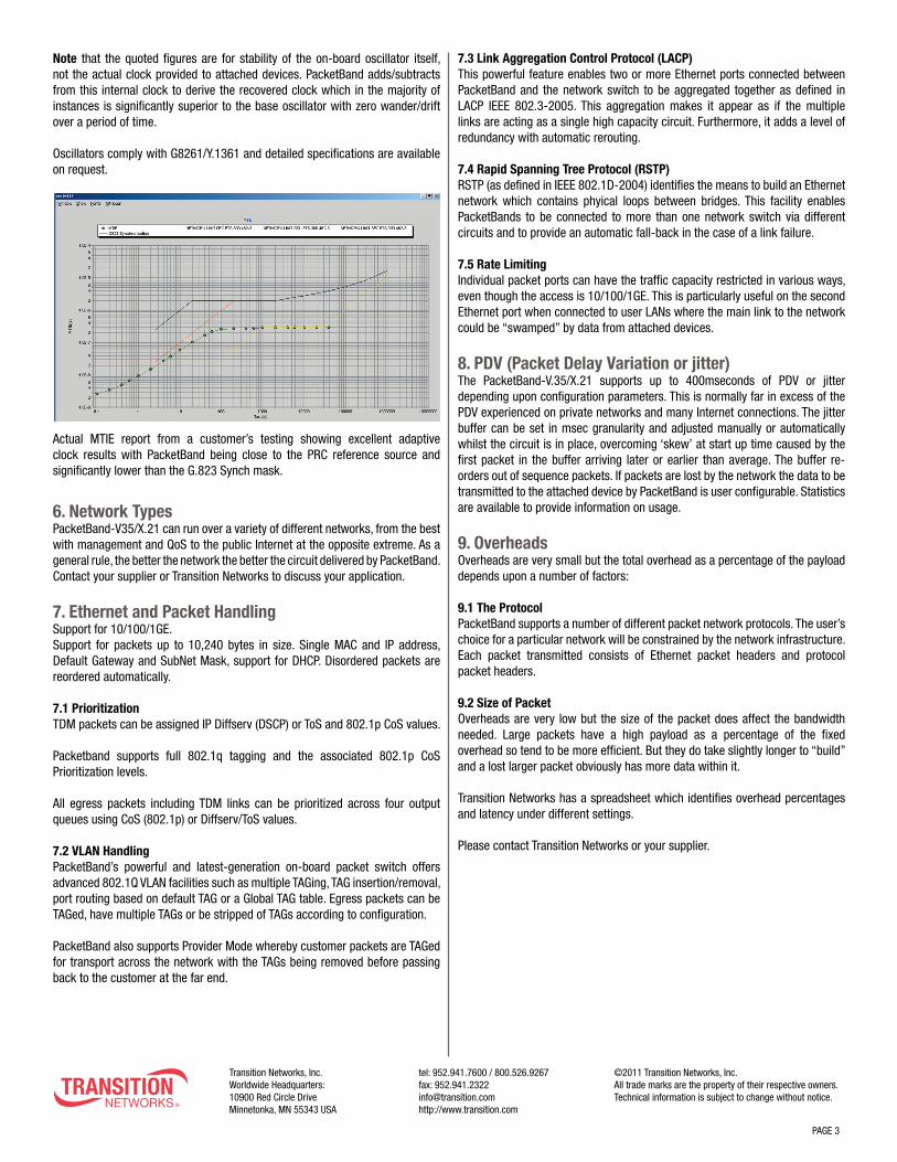
Note that the quoted figures are for stability of the on-board oscillator itself, not the actual clock provided to attached devices. PacketBand adds/subtracts from this internal clock to derive the recovered clock which in the majority of instances is significantly superior to the base oscillator with zero wander/drift over a period of time.
Oscillators comply with G8261/Y.1361 and detailed specifications are available on request.
Actual MTIE report from a customer’s testing showing excellent adaptive clock results with PacketBand being close to the PRC reference source and significantly lower than the G.823 Synch mask.
6. Network Types PacketBand-V35/X.21 can run over a variety of different networks, from the best with management and QoS to the public Internet at the opposite extreme. As a general rule, the better the network the better the circuit delivered by PacketBand. Contact your supplier or Transition Networks to discuss your application.
7. Ethernet and Packet Handling Support for 10/100/1GE. Support for packets up to 10,240 bytes in size. Single MAC and IP address, Default Gateway and SubNet Mask, support for DHCP. Disordered packets are reordered automatically.
7.1 Prioritization TDM packets can be assigned IP Diffserv (DSCP) or ToS and 802.1p CoS values.
Packetband supports full 802.1q tagging and the associated 802.1p CoS Prioritization levels.
All egress packets including TDM links can be prioritized across four output queues using CoS (802.1p) or Diffserv/ToS values.
7.2 VLAN Handling PacketBand’s powerful and latest-generation on-board packet switch offers advanced 802.1Q VLAN facilities such as multiple TAGing, TAG insertion/removal, port routing based on default TAG or a Global TAG table. Egress packets can be TAGed, have multiple TAGs or be stripped of TAGs according to configuration.
PacketBand also supports Provider Mode whereby customer packets are TAGed for transport across the network with the TAGs being removed before passing back to the customer at the far end.
7.3 Link Aggregation Control Protocol (LACP) This powerful feature enables two or more Ethernet ports connected between PacketBand and the network switch to be aggregated together as defined in LACP IEEE 802.3-2005. This aggregation makes it appear as if the multiple links are acting as a single high capacity circuit. Furthermore, it adds a level of redundancy with automatic rerouting.
7.4 Rapid Spanning Tree Protocol (RSTP) RSTP (as defined in IEEE 802.1D-2004) identifies the means to build an Ethernet network which contains phyical loops between bridges. This facility enables PacketBands to be connected to more than one network switch via different circuits and to provide an automatic fall-back in the case of a link failure.
7.5 Rate Limiting Individual packet ports can have the traffic capacity restricted in various ways, even though the access is 10/100/1GE. This is particularly useful on the second Ethernet port when connected to user LANs where the main link to the network could be “swamped” by data from attached devices.
8. PDV (Packet Delay Variation or jitter) The PacketBand-V.35/X.21 supports up to 400mseconds of PDV or jitter depending upon configuration parameters. This is normally far in excess of the PDV experienced on private networks and many Internet connections. The jitter buffer can be set in msec granularity and adjusted manually or automatically whilst the circuit is in place, overcoming ‘skew’ at start up time caused by the first packet in the buffer arriving later or earlier than average. The buffer re-orders out of sequence packets. If packets are lost by the network the data to be transmitted to the attached device by PacketBand is user configurable. Statistics are available to provide information on usage.
9. Overheads Overheads are very small but the total overhead as a percentage of the payload depends upon a number of factors:
9.1 The Protocol PacketBand supports a number of different packet network protocols. The user’s choice for a particular network will be constrained by the network infrastructure. Each packet transmitted consists of Ethernet packet headers and protocol packet headers.
9.2 Size of Packet Overheads are very low but the size of the packet does affect the bandwidth needed. Large packets have a high payload as a percentage of the fixed overhead so tend to be more efficient. But they do take slightly longer to “build” and a lost larger packet obviously has more data within it.
Transition Networks has a spreadsheet which identifies overhead percentages and latency under different settings.
Please contact Transition Networks or your supplier.

PAGE 4
Transition Networks, Inc.Worldwide Headquarters:10900 Red Circle DriveMinnetonka, MN 55343 USA
tel: 952.941.7600 / 800.526.9267fax: [email protected]://www.transition.com
©2011 Transition Networks, Inc.All trade marks are the property of their respective owners.Technical information is subject to change without notice.
10. Overheads In order to transport TDM data over the packet network, there is some overhead caused by encapsulating the data inside the packet network protocol.
10.1 The Protocol PacketBand supports a number of different packet network protocols. The user’s choice of a particular network will affect the overall size of packet headers.
10.2 Size of Packet PacketBand supports a configurable packet size per Logical Link. There is a trade off between transmitting small packets at a fast rate (low latency, larger overhead due to protocol headers) and transmitting larger packets at a slower rate (bigger latency, smaller overhead).
Typical overheads are in the 5% to 10% range. Transition Networks has a spreadsheet available which identifies overheads based on a number of different parameters. Contact Transition Networks or your supplier.
11. Latency The total end-to-end latency experienced between two devices using PacketBands is made up of four elements:
11.1 Processing Delay The latency or processing delay through each PacketBand is optimized to be as low as possible. Typical processing delay is less than 1msec.
11.2 Transmit Delay This is the time necessary to wait for sufficient incoming data to arrive from the attached device so a packet of the configured size can be built and transmitted over the network. This is typically around the 1msec range. See also 6.2 above.
11.3 Jitter Packet network networks differ in how consistently packets pass though them; some packets take more or less time than the average. PacketBand provides a synchronous clocked circuit to the attached devices and therefore has to have data ready and available for the relevant clock pulse. PacketBand buffers the fast packets so as to ensure the slow ones can arrive in time to be used. The amount of buffering is user-configurable and will depend upon the performance of the network. Note that this buffering is only required on the PacketBand receive data path and the amount of buffering needed (which equates to latency) is a result of the network, not PacketBand.
11.4 Transit Delay All IP networks have different average transit delays. These vary depending upon a large number of criteria, including the number of “hops” and whether satellites are involved. Typically, domestic links are very fast, inter-continental around 60msec and a satellite can add 250msecs. Please consult your network supplier.
Summary: between any pair of PacketBands on a terrestrial network, the most significant element contributing to latency is size of the Jitter Buffer (which is user configurable). This is directly dependant on the performance of the network and outside the control of PacketBand.
12. Management 12.1 Overview PacketBand can be locally or remotely configured using Transition’s easy-to-use high functionality DbManager GUI software.
DbLite is supplied free with each unit.
Optionally available are different versions to support requirements for larger or more integrated networks. It is sophisticated but simple to use via an intuitive Graphical User Interface (GUI) which controls, configures and monitors individual units and complete networks, currently Microsoft-based, it can also generate SNMP Traps and Alarms. The DbManager supplied with PacketBand (DbLite) allows control and visibility of a single PacketBand at any one time via a single PC. Other options support multiple real-time work-stations, a network of PacketBands and links, and have additional capabilities such as SNMP Traps & Alarms and continuous polling of devices. A document identifying the differences between DbLite and other versions is available.
Used by various organizations with different network sizes - up to and including carriers - versions of DbManager deliver a networkwide view of all PacketBands and links via a 4-layer “treestructured” overview. The status of all PacketBands and links are easy to identify with Alarms being colour coded and passed up the tree. Separate windows provide Event and Alarm information with the ability for operators to add comments etc. Different access levels and passwords provide operators with appropriate capabilities within the program.
An option to encrypt the management traffic across the packet network is available, together with a key management/ update system.
Demonstration software is available which illustrates both the DbManager and the PacketBand features. Please ask for information.
12.2. Configuration Changes Configuration changes on PacketBand are made via the DbManager. All configurations can be stored on DbManager. Installations require little or no expertise in the field as most configurations (other than IP address) can be performed remotely.
Configurations are held in non-volitile memory.
DHCP is supported.
12.3 Management Tools A wide number of statistics are available for the E1/T1 circuit and Ethernet port.

PAGE 5
Transition Networks, Inc.Worldwide Headquarters:10900 Red Circle DriveMinnetonka, MN 55343 USA
tel: 952.941.7600 / 800.526.9267fax: [email protected]://www.transition.com
©2011 Transition Networks, Inc.All trade marks are the property of their respective owners.Technical information is subject to change without notice.
12.3.1 Alarms/Events All Alarms are reported back to the DbManager and presented in a dedicated window with descriptor.
Events and Alarms are held within non-volitile memory locally in the V35/X.21 for access via DbManager.
A dry contact alarm relay is available in the RJ12 port.
12.3.2 Graphs DbManager and PacketBand provide several network monitoring tools available with graphical out-put:
• Maximum, minimum and average jitter buffer usage over time. This useful screen shows how the network and link are performing. Particularly useful information includes Lost and Late packets and jitter buffer usage figures.
• Average network jitter over time A graphical representation showing Minimum, Maximum and average buffer usage which provides important information on network performance.
• Recovered clock movement over time This graph shows frequency stability and the status of the acquiring clock.
These are invaluable tools for optimising PacketBand and for acquiring information on network performance.
These statistics, which are updated for each Logical Link every 10 seconds, gives accurate and invaluable information on the performance of the network and are vital when installing. The information also identifies whether the jitter buffer settings are correct and if the jitter buffer can be reduced to remove any unnecessary latency.
12.3.3 “Sniffer” port The second Packet port on PacketBand can be configured as a “sniffer” port duplicating TX and/or RX packets on the network Packet Port. This is a very useful diagnostic tool.
12.3.4 Loop-Backs Loops can be placed on the TDM port in either direction and at the Ethernet level.
12.3.5 Pings PacketBand generates Ping/Trace Route and responds to Ping and UDP Echo requests.
12.3.6 Boot Test Internal test on power-up with results visible via DbManager.
12.4 Software/Firmware Updates New software can be loaded via the DbManager to PacketBand- TDM. New software is loaded to the off-line sector of Flash and is confirmed via a CRC. Users can switch to the new software at any time. DbManager can load new code to multiple PacketBands simultaneously.
13. Power 13.1 Internal High-Quality AC supply Auto-sensing, standard IEC input.
13.2 Optional DC models with 48VDC or 24VDC Replaces AC supply.
14. Approvals All approvals completed in a UK Accredited laboratory. Reports available. CE marked.
Safety and Emissions (EMC) approvals (CE and FCC)
Telecoms approvals for connection to carrier leased lines is optionally available.
PacketBand V35/X.21 is RoHS compliant without the use of any “exceptions”.

PAGE 6
Transition Networks, Inc.Worldwide Headquarters:10900 Red Circle DriveMinnetonka, MN 55343 USA
tel: 952.941.7600 / 800.526.9267fax: [email protected]://www.transition.com
©2011 Transition Networks, Inc.All trade marks are the property of their respective owners.Technical information is subject to change without notice.
SpecificationsA. Clock RecoveryAdvanced algorithms tunable for different network characteristics as standard.Capable of exceeding G.823 SynchronousInterface requirements (subject to networkperformance)
B. TDM port V.35“M-Rack” 37 pin female DCE“M-Rack” 37-pin male DTESpeeds from 64kbps to 2.048Mbps
C. TDM port X.21RS530 25-way “D” connectorSpeeds from 64kbps to 2.048Mbps
D. Ethernet Interfaces2 x RJ45 UTP10/100/1GEAuto-sensing or manualSFP cage (module not supplied) forvarious fibre modes1 network and 1 or 2 user ports
E. Local Management PortRJ12AsynchronousAuto-sensing to 115kbpsAlso remote access via packet network
F. Oscillator Performance*Hold-over 24hrs 4ppbAging per day 0.5ppbTemperature Stability 14ppb
* Figures based on typical parts and perfor-mances. Individual oscillators may vary slightly either way. Temperature Stability range -5DegC to +70DegC assumes 20 minutes from power on. Aging and holdover at constant temperature
G. IP & MAC AddressSingle MAC address, IP address, subnetmask and default gatewaySupport for DHCP
H. ConfigurationHeld in non-volitile memory
I. Power (AC)Internal via IEC connectorAuto-sensing 96VAC-240VACMax consumption 0.2Amps RMS @230VACMTBF 400,000hrs
J. Power (DC)1. Nominal -48VDC4mm terminal block-33VDC to -75VDC0.35A maxMTBF 1,790,000hrs
2. Nominal -24VDC4mm terminal block-18VDC to -75VDC0.55A maxMTBF 800,000hrs
K. Dimensions & EnvironmentMetal chassis and front/rear panelsW – 225; D – 200; H – 44mmWeight – 0.9Kg/2lbOptional 19” rack-mount kit; 1 unit per 1Uor 2 units side-by-side per 1UOperating Temperature -20°C to +55°CHumidity 10-90% non-condensing
L. MaintenanceThere are no serviceable parts ormaintenance required
M. ApprovalsEMCEN55022:1988EN55014:1988EN61000-3-2/3:1995AS/NZ CISPR22:2000FCC Part 15(B)RoSH Compliant without the use ofexceptions
N. SafetyEC EN60950-1:2002ACA TS001:1997ACS/NZ60950:2000AS/NZS3260:1993IEC950
O. Telecomms (optional)TBR12/TBR13TBR4/TBR3TIA/E1A-1S/968TNA117AS-ACIF S006/S016

Transition Networks, Inc.Worldwide Headquarters:10900 Red Circle DriveMinnetonka, MN 55343 USA
tel: 952.941.7600 / 800.526.9267fax: [email protected]://www.transition.com
©2011 Transition Networks, Inc.All trade marks are the property of their respective owners.Technical information is subject to change without notice.
PAGE 7
PB/cpack/RS RS530 cable male & female. 2m
PB/cpack/X21 X.21/V.11 cable male & female. 2m
PB/cpack/MRAC V.35/V.35 MRAC male and female 2m
PB/cpack/RSM-V35F RS530 (male) to V.35 MRAC (female) 2m cable.
PB/cpack/RSF-V35M RS530 (female) to V.35 MRAC (male) 2m cable.
PB/cpack/75BNC/01 120 Ohm RJ45 to 75 Ohm dual BNC conversion cable 20cm
PB/cont Replacement serial controller cable
PacketBand-V.35/X.21Ordering Information
Part Number Description
PB-TDM-V35-DCE-AC
PB-TDM-V35-DTE-AC
PB-TDM-X21-DCE-AC
PB-TDM-X21-DTE-ACSingle X.21 port RS530 25 way female DTE, (2 UTP) 10/100/GE ports and (1xSFP) port for WAN. Includes LACP, RSTP, Enhanced Clock, serial control cable and DbManaber Lite. AC Power.
Single X.21 port RS530 25 way female DCE, (2 UTP) 10/100/GE ports and (1xSFP) port for WAN. Includes LACP, RSTP, Enhanced Clock, serial control cable and DbManaber Lite. AC Power.
Single V.35 port MRAC type 34-way female DTE, (2 UTP) 10/100/GE ports and (1xSFP) port for WAN. Includes LACP, RSTP, Enhanced Clock, serial control cable and DbManager Lite. AC power.
Single V.35 port MRAC type 34-way female DCE, (2 UTP) 10/100/GE ports and (1xSFP) port for WAN. Includes LACP, RSTP, Enhanced Clock, serial control cable and DbManager Lite. AC power.
Part Number Description
Optional Accessories
PB/RMK/3/S
PB/RMK/3/D
PB/RMK/W/1Wall mount kit (PB-TDM-1, PB-TDM-1MC, PB-TDM-4, PB-TDM-3MC, PB-TDM-V35 and PB-TDM-X21 and exteded temperature models) (Excludes chassis based systems)
19” rack kit for 2 units side by side (PB-TDM-1, PB-TDM-1MC, PB-TDM-4, PB-TDM-3MC, PB-TDM-V35 and PB-TDM-X21) (Excludes chassis based systems and extended temperature model)
19” rack kit for single unit (PB-TDM-1, PB-TDM-1MC, PB-TDM-4, PB-TDM-3MC, PB-TDM-V35 and PB-TDM-X21) (Excludes chassis based systems and extended temperature model)

Transition Networks, Inc.Worldwide Headquarters:10900 Red Circle DriveMinnetonka, MN 55343 USA
tel: 952.941.7600 / 800.526.9267fax: [email protected]://www.transition.com
©2011 Transition Networks, Inc.All trade marks are the property of their respective owners.Technical information is subject to change without notice.
PAGE 8
DbManager OptionsPart Number Description
*Other versions of DBManager are also available to support 10 and 15 concurrent work stations. Please ask for details.
DBM-NS-1-2 Single work-station DbManager with visibility/connectivity to 2 units. No SNMP Traps & Alarms
DBM-NS-1-4 Single work-station DbManager with visibility/connectivity to 4 units. No SNMP Traps & Alarms
DBM-NS-1-10 Single work-station DbManager with visibility/connectivity to 10 units. No SNMP Traps & Alarms
DBM-NS-1-25 Single work-station DbManager with visibility/connectivity to 25 units. No SNMP Traps & Alarms
DBM-NS-1-50 Single work-station DbManager with visibility/connectivity to 50 units. No SNMP Traps & Alarms
DBM-NS-1-100 Single work-station DbManager with visibility/connectivity to 100 units. No SNMP Traps & Alarms
DBM-NS-1-ULTD Single work-station DbManager with visibility/connectivity unlimited number of units. No SNMP Traps & Alarms
DBM-1-2 Single work-station DbManager with visibility/connectivity to 2 units. With SNMP Traps & Alarms
DBM-1-4 Single work-station DbManager with visibility/connectivity to 4 units. With SNMP Traps & Alarms
DBM-1-10 Single work-station DbManager with visibility/connectivity to 10 units. With SNMP Traps & Alarms
DBM-1-25 Single work-station DbManager with visibility/connectivity to 25 units. With SNMP Traps & Alarms
DBM-1-50 Single work-station DbManager with visibility/connectivity to 50 units. With SNMP Traps & Alarms
DBM-1-100 Single work-station DbManager with visibility/connectivity to 100 units. With SNMP Traps & Alarms
DBM-1-ULTD Single work-station DbManager with visibility/connectivity unlimited number of units. With SNMP Traps & Alarms
DBM-4-25 4 work-station DbManager with visibility/connectivity to 25 units. With SNMP Traps & Alarms
DBM-4-50 4 work-station DbManager with visibility/connectivity to 50 units. With SNMP Traps & Alarms
DBM-4-100 4 work-station DbManager with visibility/connectivity to 100 units. With SNMP Traps & Alarms
DBM-4-ULTD 4 work-station DbManager with visibility/connectivity to unlimited number of units. With SNMP Traps & Alarms