Embed Size (px)
Citation preview
EHG7305 / EHG7306 / EHG7307 Series
Version 1.0Updated in December, 2015
Industrial Unmanaged Gigabit Ethernet Switch
P/N:89900487G
Package Check List
Product Layout
Inside the package you will find the following items:■ Industrial Unmanaged Ethernet Switch x 1■ 7-Pin 5.08mm Lockable Terminal Block (Already mounted to the device) x 1■ DIN-Rail Kit (Already mounted to the device) x 1■ Protective caps for all SFP and PoE ports (Depend on purchased model)■ Installation Guide with Warranty Card x 1
1. PWR1 LED2. PWR2 LED3. Alarm LED
4. SFP Ports LEDs5. PoE LEDs
6. 10/100/1000 BASE-X Ports and/or 10/100/1000 BASE-X PoE Ports7. 100/1000 BASE-F(X) SFP Slot8. 1000 BASE-X SFP Slot
1. Grounding Screw2. Terminal for Power 23. Relay Output with current carrying capacity of 0.5A@24 VDC (Normal Open)
4. Terminal for Power 15. Frame Ground6. DIP Switch for SFP speed selection
Warning: Hot Surface Do Not Touch. RESTRICTED ACCESS AREA: The equipment should only be installed in a Restricted Access Area.
Never install or work on electrical or cabling during periods of lighting activity.Never connect or disconnect power when hazardous gases are present.
Caution: CLASS 1 LASER PRODUCT. Do not stare into the laser!
EHG7305
P1
1
2
3
4
5
P2
ALM
1 2
3
6
1
2
3
4
5
1 2
3 4PoE
P1 P2
ALM
EHG7305-4PoE1 2
35
6
2
1
3
4
5
6
2 3
4 5PoE
P1 P2
ALM
SFP
1
EHG7306
5
7
4
1 2
3
6 1
2
3
4
5
6
7
3 4
1 2
5 6PoE
P1 P2
ALM
SFP
EHG7307
7
8
5
4
1 2
3
6
1
5
2
3
4
1
5
2
3
4
1
5
2
3
46
Front View
EHG7305 EHG7305-4PoE EHG7306/EHG7307
Top View
V2+
V2–
V1+
V1–
F.G.
Relay
V2+
V2–
V1+
V1–
F.G.
Relay100Mbps
1Gbps
V2+
V2–
V1+
V1–
F.G.
Relay
Installation Overview
5. Next we can then proceed to connect the
device to the LAN (switch or PC, depending on
the case), take care on using the RJ-45
connector; after this we can then proceed to
the device’s settings.
The device’s appearance is as in the figure below.1. If you have purchased the wall mount kit,
proceed to place the screws on the back of the
device as shown in (Fig. 1)
2. Although internal grounding has been done
inside, in order to ensure overall maximum
performance and protect your device it is still
strongly advised to ground the device properly;
hazardous ESD can come into contact with it and
damage your equipment. On the power terminal block, there is a terminal for
Frame Ground, you can choose whether to connect it to the grounding or you may
opt to connect to the grounding screw next to the terminal block (the one chosen
should be connected at all times) (Fig. 2~4).
3. You can then choose whether to plug in the I/O ports at this point or do it later
depending on the actual location of the device or level of comfort for performing
such operation. Remember to plug in the protective caps for the unused SFP and PoE ports.
4. Once the plate has been firmly put in place,
proceed to mount the whole device as shown
in (Fig. 5).
Proceed to (Fig. 6) if you want to remove the
device from DIN-Rail.
1
2 (Fig. 5)
1
2(Fig. 6)
V2+
V2–
V1+
V1–
F.G.
Relay
(Fig. 2)
V2+
V2–
V1+
V1–
F.G.
Relay
(Fig. 3)
V2+
V2–
V1+
V1–
F.G.
Relay
(Fig. 4)
(Fig. 1)
■ The opening to the sides are for the device’s
heat dissipation please never obstruct or cover
them with any objects or try to insert them
through it. (Fig. 2~4 & Fig. 7~8)
LED Indicators
P1
P2
ALM
SFP
PoE
LAN
Green
Red
Green
Amber
Amber
Green
On
Off
On
Off
On
Blinking
Off
On
Off
On
Blinking
Off
On
Blinking
Off
Power is being supplied through this power input
Power is not supplied through this power input
Power is only supplied through PWR1 or PWR2
Power is supplied through PWR1 and PWR2
or device is not powered on
Port is linked
Data is transmitting on this port
No data is transmitting on this port
Power is being supplied to a Powered Device (PD)
Power is not supplied to a PD
Ethernet is connected at 10/100Mbps
Data is transmitting on this port
Ethernet is disconnected
Ethernet is connected at 1Gbps
Data is transmitting on this port
Ethernet is disconnected
Name Color Status Message
(Fig. 7) (Fig. 8)
Attention1. It is recommend to use at least 20 AWG cable and the cable needs to be resistant
to at least 85°C on the power connector.
2. Torque applied to the Terminal block’s screw should be 4.5 in. lb (0.51 Nm)
3. The device needs to be installed inside a Type 1 housing.
Off
Pin Assignments and Connections10/100/1000BASE-T(X) Ethernet and PoE Pinouts
RJ-45
Pin
Signal
Pin
Signal
Pin
DC
1 8
Tx+ Rx+ Rx -Tx -
10/100BASE-T(X)
BI_DA+ BI_DA- BI_DB-BI_DB+ BI_DC+ BI_DD+ BI_DD-BI_DC-
1 2 3 4 5 6 7 8
1 2 3 4 5 6 7 8
V+ V+ V-V-
1 2 3 4 5 6 7 8
1000BASE-T
PoE
Caution The SFP slot should be used in conjunction with a MSA compliant optical transceiver.
100/1000 BASE-X Fiber Optics SFP Slot
SFP Slot
SFP LC Connector Port Connection for Single-mode & Multi-mode modules
Tx
Rx
Rx
Tx
Cable Wiring
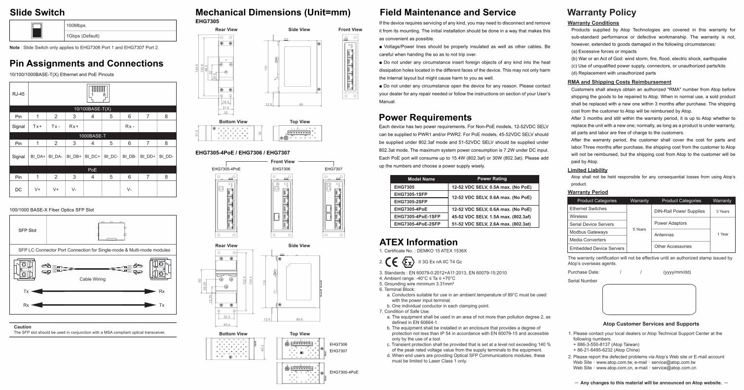
Slide Switch100Mbps
1Gbps (Default)
Note : Slide Switch only applies to EHG7306 Port 1 and EHG7307 Port 2.
Mechanical Dimensions (Unit=mm)EHG7305
EHG7305-4PoE / EHG7306 / EHG7307
P1
1
2
3
4
5
P2
ALM
V2+
V2–
V1+
V1–
F.G
.
Rel
ay
V2+
V2–
V1+
V1–
F.G
.
Rel
ay
Rear View
Bottom View Top View
Side View
Rear View
Bottom View Top View
Side View
Front View
Front View
EHG7305-4PoE
EHG7306
EHG7307
V2+
V2–
V1+
V1–
F.G
.
Rel
ay
110
12.5 90
110
12.5 89.6
31.5
32
134.
4
122.
4
5029
.25
13.7
5
32.2
45.4
45.3
134.
612
2.6
48.3
18.5
31.532
3216
.5
EHG7305-4PoE
1
2
3
4
5
1 2
3 4PoE
P1 P2
ALM
EHG7306
2
1
3
4
5
6
2 3
4 5PoE
P1 P2
ALM
SFP
1
EHG7307
1
2
3
4
5
6
7
3 4
1 2
5 6PoE
P1 P2
ALM
SFP
If the device requires servicing of any kind, you may need to disconnect and remove
it from its mounting. The initial installation should be done in a way that makes this
as convenient as possible.
■ Voltage/Power lines should be properly insulated as well as other cables. Be
careful when handing the so as to not trip over.
■ Do not under any circumstance insert foreign objects of any kind into the heat
dissipation holes located in the different faces of the device. This may not only harm
the internal layout but might cause harm to you as well.
■ Do not under any circumstance open the device for any reason. Please contact
your dealer for any repair needed or follow the instructions on section of your User’s
Manual.
Field Maintenance and Service
1. Certificate No. : DEMKO 15 ATEX 1536X
2. II 3G Ex nA IIC T4 Gc
3. Standards : EN 60079-0:2012+A11:2013, EN 60079-15:20104. Ambient range: -40°C ≤ Ta ≤ +70°C5. Grounding wire minimum 3.31mm²6. Terminal Block: a. Conductors suitable for use in an ambient temperature of 89°C must be used with the power input terminal. b. One individual conductor in each clamping point.7. Condition of Safe Use: a. The equipment shall be used in an area of not more than pollution degree 2, as defined in EN 60664-1. b. The equipment shall be installed in an enclosure that provides a degree of protection not less than IP 54 in accordance with EN 60079-15 and accessible only by the use of a tool. c. Transient protection shall be provided that is set at a level not exceeding 140 % of the peak rated voltage value from the supply terminals to the equipment. d. When end users are providing Optical SFP Communications modules, these must be limited to Laser Class 1 only.
ATEX Information
Model Name Power Rating
EHG7305 12-52 VDC SELV, 0.5A max. (No PoE)
12-52 VDC SELV, 0.6A max. (No PoE)
12-52 VDC SELV, 0.6A max. (No PoE)45-52 VDC SELV, 1.5A max. (802.3af)51-52 VDC SELV, 2.6A max. (802.3at)
EHG7305-1SFPEHG7305-2SFPEHG7305-4PoEEHG7305-4PoE-1SFPEHG7305-4PoE-2SFP
Power RequirementsEach device has two power requirements. For Non-PoE models, 12-52VDC SELV
can be supplied to PWR1 and/or PWR2. For PoE models, 45-52VDC SELV should
be supplied under 802.3af mode and 51-52VDC SELV should be supplied under
802.3at mode. The maximum system power consumption is 7.2W under DC input.
Each PoE port will consume up to 15.4W (802.3af) or 30W (802.3at). Please add
up the numbers and choose a power supply wisely.
Customers shall always obtain an authorized "RMA" number from Atop before shipping the goods to be repaired to Atop. When in normal use, a sold product shall be replaced with a new one within 3 months after purchase. The shipping cost from the customer to Atop will be reimbursed by Atop.After 3 months and still within the warranty period, it is up to Atop whether to replace the unit with a new one; normally, as long as a product is under warranty, all parts and labor are free of charge to the customers.After the warranty period, the customer shall cover the cost for parts and labor.Three months after purchase, the shipping cost from the customer to Atop will not be reimbursed, but the shipping cost from Atop to the customer will be paid by Atop.
Atop shall not be held responsible for any consequential losses from using Atop’s
product.
Warranty Policy
The warranty certification will not be effective until an authorized stamp issued by Atop’s overseas agents.
Purchase Date: / / (yyyy/mm/dd)
Serial Number
Product CategoriesWarranty WarrantyProduct Categories
Media Converters
Embedded Device Servers
Ethernet Switches
Wireless
Serial Device Servers
Modbus Gateways
DIN-Rail Power Supplies
Power Adaptors
Antennas
Other Accessories
Warranty Conditions
RMA and Shipping Costs Reimbursement
Limited Liability
1. Please contact your local dealers or Atop Technical Support Center at the following numbers. + 886-3-550-8137 (Atop Taiwan) + 86-21-6495-6232 (Atop China)2. Please report the defected problems via Atop’s Web site or E-mail account Web Site:www.atop.com.tw, e-mail:[email protected] Web Site:www.atop.com.cn, e-mail:[email protected]
Atop Customer Services and Supports
Products supplied by Atop Technologies are covered in this warranty for sub-standard performance or defective workmanship. The warranty is not, however, extended to goods damaged in the following circumstances:(a) Excessive forces or impacts(b) War or an Act of God: wind storm, fire, flood, electric shock, earthquake(c) Use of unqualified power supply, connectors, or unauthorized parts/kits(d) Replacement with unauthorized parts
Warranty Period
─ Any changes to this material will be announced on Atop website. ─


![DOCUMENTS CHECK LIST OF A LOAN PACKAGE - e …sites.e-agents.com/Uploads/49/75/14975/Gallery/... · · 2011-06-17slav real estate [documents check list of a loan package] 14375](https://img.pdfslide.us/doc/110x75/5ae1f3c17f8b9ae74a8bd57d/documents-check-list-of-a-loan-package-e-sitese-real-estate-documents-check.jpg)