Embed Size (px)
Citation preview
Pacific Gas and Electric Company
EPIC F ina l Report
Program Electric Program Investment Charge (EPIC)
Project EPIC 1.09C – Test New Remote Monitoring and Control Systems for T&D Assets, Discrete Series Reactors
Reference Name Discrete Series Reactors (DSR)
Department Transmission System Operations Sponsor Tom French
Business Lead Sherman Chen
Date 12/29/2016
Version Type Final
Contact [email protected]
EPIC Final Report 1.09C DSR Demonstration Project
Table of Contents 1.0 Executive Summary ____________________________________________________________ 1
2.0 Introduction __________________________________________________________________ 9
3.0 Project Overview _____________________________________________________________ 10
Project Objective_________________________________________________________ 10 3.1
Issue Addressed _________________________________________________________ 10 3.2
DSR Technology _________________________________________________________ 11 3.3
Scope of Work ___________________________________________________________ 14 3.4
4.0 Major Tasks, Deliverables and Results _____________________________________________ 16
Planning _______________________________________________________________ 16 4.1
Line Selection ...................................................................................................... 16 4.1.1
Power Flow Simulations ...................................................................................... 16 4.1.2
Engineering _____________________________________________________________ 17 4.2
Transmission Engineering .................................................................................... 17 4.2.1
Conductor Testing / Inspection............................................................................ 17 4.2.2
Construction ____________________________________________________________ 17 4.3
DSRs Unit Installation .......................................................................................... 18 4.3.1
Telecommunications / Software Installation ........................................................ 19 4.3.2
Commissioning/Initial Testing_______________________________________________ 20 4.4
Acceptance Testing ............................................................................................. 20 4.4.1
Power Line Carrier Testing................................................................................... 22 4.4.2
Functional Testing ________________________________________________________ 22 4.5
Power Flow Control ............................................................................................. 23 4.5.1
Phase Unbalance Reduction ................................................................................ 24 4.5.2
Operational Testing ______________________________________________________ 25 4.6
Availability .......................................................................................................... 25 4.6.1
Reliability ............................................................................................................ 28 4.6.2
Cost Review _____________________________________________________________ 28 4.7
5.0 Summary of Learnings and Next Steps _____________________________________________ 30
6.0 Data Access__________________________________________________________________ 33
7.0 Value Proposition _____________________________________________________________ 34
Primary EPIC Guiding Principles _____________________________________________ 34 7.1
Secondary Principles of EPIC ________________________________________________ 35 7.2
8.0 Technology Transfer Plan _______________________________________________________ 36
PG&E’s Technology Transfer Plans ___________________________________________ 36 8.1
Adaptability to Other Utilities / Industry ______________________________________ 36 8.2
9.0 Metrics _____________________________________________________________________ 37
10.0 Conclusion __________________________________________________________________ 38
EPIC Final Report 1.09C DSR Demonstration Project
List of Tables Table 4-1 Power Flow Results ..............................................................................................................17
Table 4-2 Issues/Solutions during Operational Testing .........................................................................27
Table 4-3 Percent Availability of the DSRs by Week .............................................................................27
Table 5-1 Planning, Engineering and Construction Learnings................................................................31
Table 5-2 Telecommunication Learnings ..............................................................................................32
Table 5-3 Functional Learnings ............................................................................................................32
Table 7-1 EPIC Primary and Secondary Principles .................................................................................34
Table 9-1 Proposed Metrics and Potential Areas of Measurement .......................................................37
List of Figures Figure 3-1 DSR on a Transmission Line .................................................................................................11
Figure 3-2 Schematic of DSR Project ....................................................................................................12
Figure 3-3 DSR Component Diagram ....................................................................................................13
Figure 3-4 Relationship between Current and DSR Inductance .............................................................14
Figure 4-1 Tower on Las Positas-Newark 230 kV line with 6 units installed and Crew Installing Unit .....19
Figure 4-2 DSR State with 6 Units in Injection ......................................................................................21
Figure 4-3 Phase Currents and Inductance ...........................................................................................22
Figure 4-4 Current & Inductance in Manual Control .............................................................................23
Figure 4-5 Current & Inductance Over 7 Days in Set Point Control .......................................................24
Figure 4-6 Phase Currents with DSRs on Phase A Only Injecting ...........................................................25
Figure 4-7 Percent Availability of DSRs by Week ..................................................................................28
List of Acronyms
CIP Critical Infrastructure Protection
CPUC California Public Utilities Commission
D-FACTS Distributed Flexible AC Transmission System
DSR Distributed Series Reactor
EMS Energy Management System
EPIC Electric Program Investment Charge
FFIOC Fairfield Information Operations Center
ISM Industrial, Scientific, and Medical radio band
LP-N Las Positas-Newark 230 kV line
NERC North American Reliability Corporation
NIB Network Interface Bridge
ODN Operational Data Network
SFIOC San Francisco Information Operations Center
SPS Special Protection System
TD&D Technology Demonstration and Deployment
1
1.0 Executive Summary
Pacific Gas and Electric Company’s (PG&E) Electric Program Investment Charge (EPIC) Project 1.09C Discrete Series Reactors successfully developed and demonstrated a new technology deployed directly onto transmission conductors to detect potential overloads and increase line impedance to shift this load to parallel facilities1. These devices are known as Distributed Series Reactors (DSR). When energized, each DSR utilizes the magnetizing reactance of internal injection transformer to insert inductance in series with the line.
PG&E and the technology provider worked collaboratively throughout the demonstration to (1) improve the technology provider’s installation tool, (2) develop installation work methods using a helicopter and (3) address multiple issues that arose with the operation of the units and led to several firmware modifications.
Issue Addressed
A challenge for utilities is excessive load imports or generation exports causing overloads on overhead transmission lines, when electrical current exceeds maximum rated capacity. Overloads can potentially cause asset damage or create a safety hazard with the line. As such, when transmission facilities exceed their rated capacity, utilities are required to mitigate these overloads to comply with North American Electric Reliability Corporation (NERC) standards2.
The nature of the mitigation of an overload depends on whether the issue occurs with all lines in service (N-0), or a single line (N-1) or multiple lines (for example, N-1-1 or N-2) out of service. In the event of an emergency overload due to a simultaneous outage of two lines, PG&E has deployed special protection systems (SPS) load tripping (among other actions) in certain locations. This system of relays and a centralized controller will drop load in response to line rating violations in order to protect assets from further loss.
Often, mitigation of overloads will lead to investments to increase capacity by installing new transmission lines or reconductoring of existing lines. In order to plan such investments, utilities leverage load forecasts and generation dispatch scenarios to understand the needed capacity on the transmission system. However, system needs can change over time. A conventional upgrade in a load pocket to eliminate an overload may not be needed in in the long-run as transmission loadings decrease due to increasing levels of DERs. In addition to their permanence, traditional capacity upgrades are costly and can take many years to deploy.
Another challenge in the utility industry is congestion which occurs when scheduled market transactions between generation and load exceed the capability of a transmission element. To mitigate congestion, alternative resources (which could potentially be more costly and less desirable) may be accessed to supply load using other less loaded transmission facilities. Less flexibility in the source of generation may limit the ability to access Distributed Energy Resources (DERs) or renewables.
DSRs, installed on conductors on select lines and controlled remotely or pre-programmed with certain settings, can vary their impact based on observed loading conditions, ultimately allowing the utility to potentially optimize generation resources, optimize line flows, mitigate normal overloads, and delay costly new transmission line or reconductoring projects. As compared to traditional transmission investments, DSRs can be deployed several years faster at a significantly lower cost. Additionally, DSRs offer portability and flexibility.
1 Parallel facilities consist of two or more system elements (lines, transformers) that are in service between source and load.
2 NERC Reliability Standards: http://www.nerc.com/pa/stand/Pages/ReliabilityStandardsUnitedStates.aspx?jurisdiction=United%20States
2
Traditional upgrades are permanent installations. Conversely, DSRs could be installed to eliminate the temporary overload and then relocated to another location when that overload condition disappears. Additionally, in the case of emergency double line outages, DSRs could potentially reduce the need for SPS load tripping by reducing overloads, thereby potentially further minimizing reliability impacts.
In addition to reduction of overall load on a line, DSRs could be leveraged to reduce unbalance among the line’s three phases. A significant current unbalance could potentially impact customer equipment. While unbalance is generally well-managed on utility transmission lines, incremental improvement could be leveraged to potentially avoid customer equipment impacts should the need arise.
Primary Objective
The primary objective of EPIC 1.09C is to gain operational experience and demonstrate the safe and effective operation of DSRs on PG&E’s transmission system to reduce line flow. The project installed 90 DSRs on PG&E’s Las Positas-Newark 230 kV line (LP-N), along with associated communication and control equipment.
Key Accomplishments and Results
Planning: Originally, the Ravenswood-San Mateo 115 kV line was selected for project implementation. This line was selected as it has SPS load tripping deployed, and presented a potential opportunity to demonstrate the potential reduction of the need for this scheme. However, analysis on the conductor and structures concluded that the installation of DSRs (212 pounds, each) on this line posed too high a risk of a conductor break. This concern was driven by this line’s 90-year age and the salt air environment in which it has operated. After additional detailed analysis, the Las Positas-Newark (LP-N) 230 kV line was selected for this project. The line conductor and structures were shown to have sufficient strength for the DSRs due to line material and size (795 ACSR, 54/73) and location (less exposure to salt air environment). Additionally, power flow simulations showed that the injection of 90 DSR units on this line would increase the impedance of the line by about 3 percent and reduce the flow by about 1 percent.
Engineering: PG&E engineers conducted a review of deployment feasibility based on an evaluation of the various line elements (conductor, structure, insulators) with respect to engineering standards. Results showed that the conductor had sufficient tensile strength; however, the 230 kV insulators should be replaced to assure the added weight would not cause the insulator to fail and new dampers should be installed on the span side of DSRs to mitigate vibration and potential conductor damage.
Construction: 90 DSR units were installed on the conductor, in groups of six units near 15 towers. In each group, a DSR with a Network Interface Bridge (NIB) utilized cellular service to communicate with the other DSRs and with the DSR web interface. The DSR web interface provided central management and operator level control of NIB managed DSR networks.
Commissioning/Initial Testing: Once installed, PG&E performed an initial verification that the DSRs could communicate without impact to critical fault protection communication systems and produce inductance as specified by the vendor.
3 Aluminum Conductor Steel Reinforced Cable (ACSR), with 795 American Wire Gauge (AWG) size, and 54/7 Aluminum / Steel Stranding.

3
o Acceptance: Conducted to verify end-to-end communication between the DSR server in San Francisco and each unit. This test also verified that each unit produced an inductance of at least 42 microhenries (µH )4, per vendor specification. Results showed that this specification was met.
o Power Line Carrier: Conducted to determine whether the injection of the 90 DSRs would impact the communications (Power Line Carrier) of the transfer trip scheme used as primary fault protection on the Las Positas-Newark 230 kV line. Testing involved measuring the signal strength of the Power Line Carrier while DSRs were in operation. Results demonstrated that the Power Line Carrier would operate satisfactorily while the DSRs were in injection mode.
Functional Testing: PG&E tested the functional performance of the DSRs, including the ability to reduce line flow and phase unbalance.
o Power Flow Control: Conducted to demonstrate the ability of the DSRs to impact flow on the Las
Positas-Newark line. Testing showed that the DSRs could be controlled manually changing line flow by 1-2%. Additionally testing showed that under set-point control the DSRs switch in and out of injection when power flow increased and decreased on the line when pre-set current flows were reached resulting in a similar 1-2% change in flow.
o Phase Unbalance Reduction: Conducted to demonstrate the ability of the DSRs to reduce phase unbalance. Testing showed that by leveraging the DSRs in injection mode on one of three phases, the current on this phase would decrease to approximately the level of the other two phases.
Operational Testing: PG&E tested key operational measures, including availability and reliability of the units. The DSRs were monitored for a 6-month period covering warm weather and summer peak conditions.
o Availability: Availability testing measured the percentage of time the DSR units were
communicating with no more than a 60 second lag between successive scans. This metric excluded the time when the Las Positas-Newark 230 kV line was scheduled out of service for planned maintenance. The target for the availability metric was 98%. This number was chosen as a baseline for the demonstration, to represent a potentially tolerable level of availability and could provide an indication of possible additional investment in DSRs (2% above needed amount) to cover for the units that might be unavailable. PG&E collaborated with the technology supplier to improve the availability of the DSRs throughout this phase of testing through firmware updates. These updates included varying the frequencies that the NIBs communicated on, so as not to interfere with one another. By project completion, the results showed 99.9% availability.
o Reliability: Evaluated the percentage of time that available units were in the correct operating state (injection or monitor). The analysis showed that the DSRs were in the correct operating state 99.99% of the time.
4 A microhenry (µH) is a unit of inductance, a component of the impedance in an AC power system. In this case, the DSRs increase the overall inductance (or impedance) of an AC transmission line on which they are installed.
4
Cost Review: PG&E conducted a review of both construction and on-going operation and maintenance (O&M) costs of the DSRs. Analysis showed that thermal overloading of another PG&E 230kV line could be mitigated by (a) reconductoring at an estimated cost of approximately $130 million, or (b) installing approximately 2,000 DSR units on this line at an estimated cost of approximately $33 million—25% of the cost of reconductoring – with a relatively low ongoing O&M cost for annual software licensing for the control and monitoring, operating system updates, and cellular fees for data transfer (e.g., for 90 DSRs this cost is ~$5,000). DSRs were considered a feasible alternative for this situation. However, based on the latest transmission planning study results, the need for the project is being reconsidered in light of significantly lower thermal overloads due to lower load forecasts resulting from increased levels of forecasted Distributed Energy Resources and energy efficiency.
Key Learnings and Next Steps
PG&E produced several key learnings and next steps to be explored with regards to DSRs. Learnings have been categorized as related to planning/engineering/construction, telecommunications, or functional.
PG&E produced the following functional learnings related to DSRs in an operational environment, and as such PG&E will explore the following next steps:
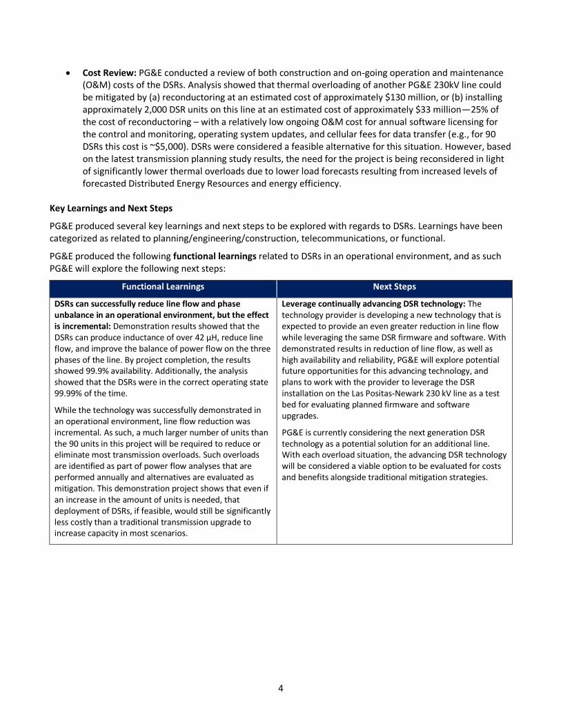
Functional Learnings Next Steps
DSRs can successfully reduce line flow and phase unbalance in an operational environment, but the effect is incremental: Demonstration results showed that the DSRs can produce inductance of over 42 µH, reduce line flow, and improve the balance of power flow on the three phases of the line. By project completion, the results showed 99.9% availability. Additionally, the analysis showed that the DSRs were in the correct operating state 99.99% of the time.
While the technology was successfully demonstrated in an operational environment, line flow reduction was incremental. As such, a much larger number of units than the 90 units in this project will be required to reduce or eliminate most transmission overloads. Such overloads are identified as part of power flow analyses that are performed annually and alternatives are evaluated as mitigation. This demonstration project shows that even if an increase in the amount of units is needed, that deployment of DSRs, if feasible, would still be significantly less costly than a traditional transmission upgrade to increase capacity in most scenarios.
Leverage continually advancing DSR technology: The technology provider is developing a new technology that is expected to provide an even greater reduction in line flow while leveraging the same DSR firmware and software. With demonstrated results in reduction of line flow, as well as high availability and reliability, PG&E will explore potential future opportunities for this advancing technology, and plans to work with the provider to leverage the DSR installation on the Las Positas-Newark 230 kV line as a test bed for evaluating planned firmware and software upgrades.
PG&E is currently considering the next generation DSR technology as a potential solution for an additional line. With each overload situation, the advancing DSR technology will be considered a viable option to be evaluated for costs and benefits alongside traditional mitigation strategies.
5
Engineering and construction of the DSRs produced the following learnings, and as such PG&E will explore the following next steps for any new potential installations:
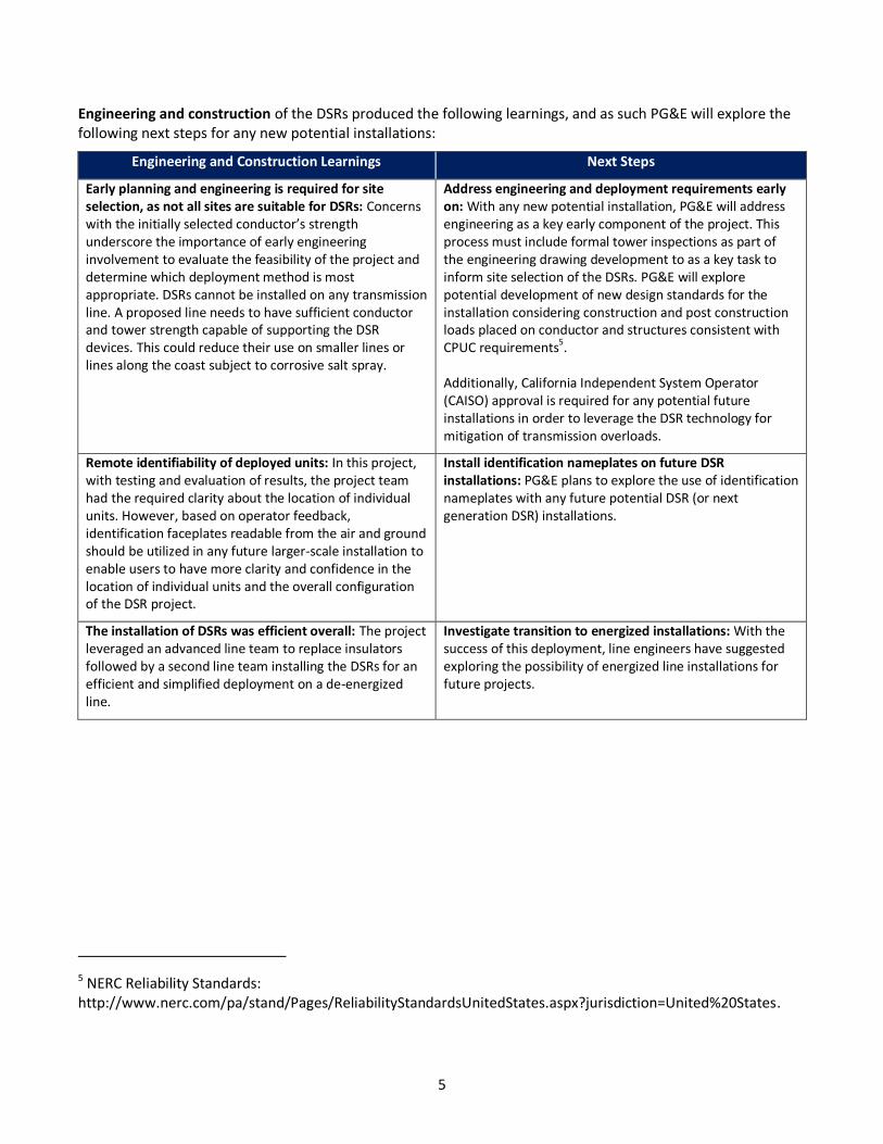
Engineering and Construction Learnings Next Steps
Early planning and engineering is required for site selection, as not all sites are suitable for DSRs: Concerns with the initially selected conductor’s strength underscore the importance of early engineering involvement to evaluate the feasibility of the project and determine which deployment method is most appropriate. DSRs cannot be installed on any transmission line. A proposed line needs to have sufficient conductor and tower strength capable of supporting the DSR devices. This could reduce their use on smaller lines or lines along the coast subject to corrosive salt spray.
Address engineering and deployment requirements early on: With any new potential installation, PG&E will address engineering as a key early component of the project. This process must include formal tower inspections as part of the engineering drawing development to as a key task to inform site selection of the DSRs. PG&E will explore potential development of new design standards for the installation considering construction and post construction loads placed on conductor and structures consistent with CPUC requirements5. Additionally, California Independent System Operator (CAISO) approval is required for any potential future installations in order to leverage the DSR technology for mitigation of transmission overloads.
Remote identifiability of deployed units: In this project, with testing and evaluation of results, the project team had the required clarity about the location of individual units. However, based on operator feedback, identification faceplates readable from the air and ground should be utilized in any future larger-scale installation to enable users to have more clarity and confidence in the location of individual units and the overall configuration of the DSR project.
Install identification nameplates on future DSR installations: PG&E plans to explore the use of identification nameplates with any future potential DSR (or next generation DSR) installations.
The installation of DSRs was efficient overall: The project leveraged an advanced line team to replace insulators followed by a second line team installing the DSRs for an efficient and simplified deployment on a de-energized line.
Investigate transition to energized installations: With the success of this deployment, line engineers have suggested exploring the possibility of energized line installations for future projects.
5 NERC Reliability Standards: http://www.nerc.com/pa/stand/Pages/ReliabilityStandardsUnitedStates.aspx?jurisdiction=United%20States.
6
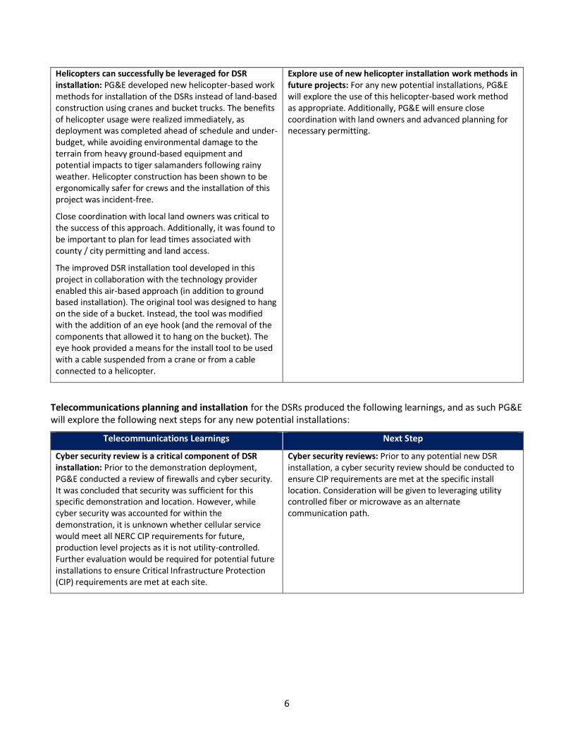
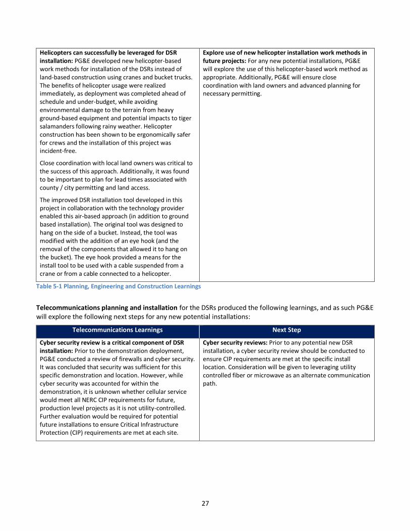
Helicopters can successfully be leveraged for DSR installation: PG&E developed new helicopter-based work methods for installation of the DSRs instead of land-based construction using cranes and bucket trucks. The benefits of helicopter usage were realized immediately, as deployment was completed ahead of schedule and under-budget, while avoiding environmental damage to the terrain from heavy ground-based equipment and potential impacts to tiger salamanders following rainy weather. Helicopter construction has been shown to be ergonomically safer for crews and the installation of this project was incident-free.
Close coordination with local land owners was critical to the success of this approach. Additionally, it was found to be important to plan for lead times associated with county / city permitting and land access.
The improved DSR installation tool developed in this project in collaboration with the technology provider enabled this air-based approach (in addition to ground based installation). The original tool was designed to hang on the side of a bucket. Instead, the tool was modified with the addition of an eye hook (and the removal of the components that allowed it to hang on the bucket). The eye hook provided a means for the install tool to be used with a cable suspended from a crane or from a cable connected to a helicopter.
Explore use of new helicopter installation work methods in future projects: For any new potential installations, PG&E will explore the use of this helicopter-based work method as appropriate. Additionally, PG&E will ensure close coordination with land owners and advanced planning for necessary permitting.
Telecommunications planning and installation for the DSRs produced the following learnings, and as such PG&E will explore the following next steps for any new potential installations:
Telecommunications Learnings Next Step
Cyber security review is a critical component of DSR installation: Prior to the demonstration deployment, PG&E conducted a review of firewalls and cyber security. It was concluded that security was sufficient for this specific demonstration and location. However, while cyber security was accounted for within the demonstration, it is unknown whether cellular service would meet all NERC CIP requirements for future, production level projects as it is not utility-controlled. Further evaluation would be required for potential future installations to ensure Critical Infrastructure Protection (CIP) requirements are met at each site.
Cyber security reviews: Prior to any potential new DSR installation, a cyber security review should be conducted to ensure CIP requirements are met at the specific install location. Consideration will be given to leveraging utility controlled fiber or microwave as an alternate communication path.

7
The number of NIBs impacts communication latency of commands: During initial testing, commands from the Server were taking too long (up to 5 minutes) to implement due primarily to the fact that NIBs were connected to up to 18-24 units. PG&E believed this latency to be unacceptable for the demonstration. As such, an additional 8 NIBs were activated so that each NIB was connected to 6 units at each of the 15 structures. This significantly reduced the latency.
Include impact of latency in establishing of the number of NIBs: In a potential production project, units would likely operate in set-point control most of the time. However, there can be situations in which the operator might be required to issue an emergency command from the server. As such, for any future potential DSR (or next generation technology) deployments, PG&E will consider this learning in order to establish an appropriate number of NIBs to manage latency.
Conclusion
PG&E achieved its primary objective for the EPIC 1.09C project through gaining operational experience and demonstrating the safe and effective operation of DSRs on PG&E’s transmission system to reduce line flow. The project demonstrated that DSRs can reduce line flow and phase imbalance while maintaining high availability and reliability and minimizing impact to primary protection communications.
PG&E collaborated with the technology supplier to continue development of the availability of this new technology, improve the installation tool and develop new installation work methods. Based on the engineering, installation and testing that has been completed, the DSR technology could potentially be leveraged for several applications, such as overload reduction or elimination, and improved reliability by reducing or eliminating special protection scheme tripping used to mitigate thermal overloads and reducing transmission congestion.
DSRs cannot be installed on any transmission line. A proposed line needs to have sufficient conductor and tower strength capable of supporting the DSR devices. This could reduce their use on smaller lines or lines along the coast subject to corrosive salt spray. PG&E will address engineering as a key early component of any future potential project, including formal tower inspections.
While DSRs can successfully reduce line flow in an operational environment, to mitigate any sizable line overload in a networked transmission system would require many hundreds of these units. Regardless, this demonstration shows that even if an increase in the amount of units is needed, that deployment of DSRs would still be significantly less costly than a traditional transmission upgrade to increase capacity in most scenarios.
In response to the incremental impact of DSRs, the technology provider is developing a new technology that is expected to provide an even greater reduction in line flow while leveraging the same DSR firmware and software. PG&E will explore potential future opportunities for this advancing technology, and will explore collaboration with the provider to leverage the Las Positas-Newark 230 kV line installation as a test bed for evaluating planned firmware and software upgrades for supporting this and the other related technologies.
Based on this technology demonstration project, it has been determined that the advancing DSR technology can potentially be used on the PG&E transmission system subject to completion of the following:
1. Development of new design standards for the installation considering construction and post construction loads placed on conductor and structures consistent with CPUC requirements;
2. Evaluation of CIP (Critical Infrastructure Protection) requirements (i.e., physical security and electronic security) and identify any issues/concerns and develop mitigation;
3. Determination of the extra percentage of units needed to account for a less than 100% availability; and 4. Obtainment of CAISO approval to install future project.
PG&E is currently considering the advancing DSR technology as a potential solution for an additional line, subject to CAISO approval. With each overload situation, the advancing DSR technology will be considered a viable option to be evaluated for costs and benefits alongside traditional mitigation strategies.
8
2.0 Introduction
This report documents the EPIC 1.09C Discrete Reactors achievements, highlights key learnings that have industry-wide value, and identifies future opportunities for PG&E to leverage this project.
The California Public Utilities Commission (CPUC) passed two decisions that established the basis for this pilot program. The CPUC initially issued D. 11-12-035, Decision Establishing Interim Research, Development and Demonstrations and Renewables Program Funding Level6, which established the Electric Program Investment Charge (EPIC) on December 15, 2011. Subsequently, on May 24, 2012, the CPUC issued D. 12-05-037, Phase 2 Decision Establishing Purposes and Governance for Electric Program Investment Charge and Establishing Funding Collections for 2013-20207, which authorized funding in the areas of applied research and development, technology demonstration and deployment (TD&D), and market facilitation. In this later decision, CPUC defined TD&D as “the installation and operation of pre-commercial technologies or strategies at a scale sufficiently large and in conditions sufficiently reflective of anticipated actual operating environments to enable appraisal of the operational and performance characteristics and the financial risks associated with a given technology.”8
The decision also required the EPIC Program Administrators9 to submit Triennial Investment Plans to cover three-year funding cycles for 2012-2014, 2015-2017, and 2018-2020. On November 1, 2012, in A.12-11-003, PG&E filed its first triennial Electric Program Investment Charge (EPIC) Application at the CPUC, requesting $49,328,000 including funding for 26 Technology Demonstration and Deployment Projects. On November 14, 2013, in D.13-11-025, the CPUC approved PG&E’s EPIC plan, including $49,328,000 for this program category. Pursuant to PG&E’s approved EPIC triennial plan, PG&E initiated, planned and implemented EPIC 1.09C Discrete Reactors. Through the annual reporting process, PG&E kept CPUC staff and stakeholders informed on the progress of the project. The following is PG&E’s final report on this project.
3.0 Project Overview
EPIC 1.09C installed Distributed Series Reactors (DSRs) on a transmission line (Las Positas – Newark 230kV) and monitored and controlled their operation for six months. This technology demonstration project included the deployment of 90 DSRs and associated communications equipment, and the hardware and software needed to monitor and control the DSR modules.
Project Objective 3.1
The primary objective of EPIC 1.09C is to gain operational experience and demonstrate the safe and effective operation of DSRs on PG&E’s transmission system to reduce line flow. The project installed 90 DSRs and associated communication and control equipment on PG&E’s Las Positas-Newark 230 kV line.
To meet the project objective, PG&E and the technology provider worked collaboratively throughout the demonstration project. These efforts led to (1) improvements to the technology provider’s installation tool based on feedback from the PG&E team, (2) development installation work methods using helicopter to transport the installation tool and DSRs to each of the sites, and (3) improvements to technology provider’s firmware to addressing multiple communication problems that arose during the test period.
6 http://docs.cpuc.ca.gov/PublishedDocs/WORD_PDF/FINAL_DECISION/156050.PDF. 7 http://docs.cpuc.ca.gov/PublishedDocs/WORD_PDF/FINAL_DECISION/167664.PDF. 8 Decision 12-05-037 pg. 37. 9 Pacific Gas & Electric (PG&E), San Diego Gas & Electric (SDG&E), Southern California Edison (SCE), and the California Energy Commission (CEC).

9
Issue Addressed 3.2
A challenge for utilities is excessive load imports or generation exports causing overloads on overhead transmission lines, when electrical current exceeds maximum rated capacity. Overloads can potentially cause asset damage or create a safety hazard with the line. As such, when transmission facilities exceed their rated capacity, utilities are required to mitigate these overloads to comply with North American Electric Reliability Corporation (NERC) standards10.
The nature of the mitigation of an overload depends on whether the issue occurs with all lines in service (N-0), or a single line (N-1) or multiple lines (for example, N-1-1 or N-2) out of service. In the event of an emergency overload due to a simultaneous outage of two lines, PG&E has deployed special protection systems (SPS) load tripping (among other actions) in certain locations. This system of relays and a centralized controller will drop load in response to line rating violations in order to protect assets from further loss.
Often, mitigation of overloads will lead to investments to increase capacity by installing new transmission lines or reconductoring of existing lines. In order to plan such investments, utilities leverage load forecasts and generation dispatch scenarios to understand the needed capacity on the transmission system. However, system needs can change over time. A conventional upgrade in a load pocket to eliminate an overload may not be needed in in the long-run as transmission loadings decrease due to increasing levels of DERs. In addition to their permanence, traditional capacity upgrades are costly and can take many years to deploy.
Another challenge in the utility industry is congestion which occurs when scheduled market transactions between generation and load exceed the capability of a transmission element. To mitigate congestion, alternative resources (which could potentially be more costly and less desirable) may be accessed to supply load using other less loaded transmission facilities. Less flexibility in the source of generation may limit the ability to access Distributed Energy Resources (DERs) or renewables.
DSRs, installed on conductors on select lines and controlled remotely or pre-programmed with certain settings, can vary their impact based on observed loading conditions, ultimately allowing the utility to potentially optimize generation resources, optimize line flows, mitigate normal overloads, and delay costly new transmission line or reconductoring projects. As compared to traditional transmission investments, DSRs can be deployed several years faster at a significantly lower cost. Additionally, DSRs offer portability and flexibility. Traditional upgrades are permanent installations. Conversely, DSRs could be installed to eliminate the temporary overload and then relocated to another location when that overload condition disappears. Additionally, in the case of emergency double line outages, DSRs could potentially reduce the need for SPS load tripping by reducing overloads, thereby potentially further minimizing reliability impacts.
In addition to reduction of overall load on a line, DSRs could be leveraged to reduce unbalance among the line’s three phases. A significant current unbalance could impact customer equipment. While unbalance is generally well-managed on utility transmission lines, incremental improvement could be leveraged to potentially avoid customer equipment impacts should the need arise.
Prior to the initiation of this demonstration, DSRs had been researched and tested by Georgia Tech’s National Electric Energy Testing, Research and Applications Center (NEETRAC)11, illustrating the viability of these devices. However, the DSRs had not yet been demonstrated in the field in a drier climate in the West. PG&E and the technology provider worked collaboratively throughout the demonstration to (1) improve the technology
10 NERC Reliability Standards: http://www.nerc.com/pa/stand/Pages/ReliabilityStandardsUnitedStates.aspx?jurisdiction=United%20States.
11 http://www.smartwires.com/wp-content/uploads/2015/01/Smart_Wire_3.pdf.
10
provider’s installation tool, (2) develop installation work methods using helicopter and (3) address multiple issues that arose with the operation of the units and led to several firmware modifications.
DSR Technology 3.3
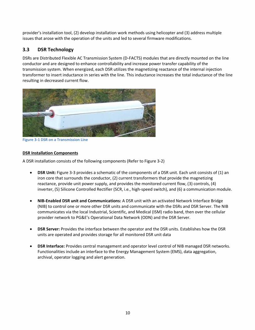
DSRs are Distributed Flexible AC Transmission System (D-FACTS) modules that are directly mounted on the line conductor and are designed to enhance controllability and increase power transfer capability of the transmission system. When energized, each DSR utilizes the magnetizing reactance of the internal injection transformer to insert inductance in series with the line. This inductance increases the total inductance of the line resulting in decreased current flow.
Figure 3-1 DSR on a Transmission Line
DSR Installation Components
A DSR installation consists of the following components (Refer to Figure 3-2)
DSR Unit: Figure 3-3 provides a schematic of the components of a DSR unit. Each unit consists of (1) an iron core that surrounds the conductor, (2) current transformers that provide the magnetizing reactance, provide unit power supply, and provides the monitored current flow, (3) controls, (4) inverter, (5) Silicone Controlled Rectifier (SCR, i.e., high-speed switch), and (6) a communication module.
NIB-Enabled DSR unit and Communications: A DSR unit with an activated Network Interface Bridge (NIB) to control one or more other DSR units and communicate with the DSRs and DSR Server. The NIB communicates via the local Industrial, Scientific, and Medical (ISM) radio band, then over the cellular provider network to PG&E’s Operational Data Network (ODN) and the DSR Server.
DSR Server: Provides the interface between the operator and the DSR units. Establishes how the DSR units are operated and provides storage for all monitored DSR unit data
DSR Interface: Provides central management and operator level control of NIB managed DSR networks. Functionalities include an interface to the Energy Management System (EMS), data aggregation, archival, operator logging and alert generation.
11
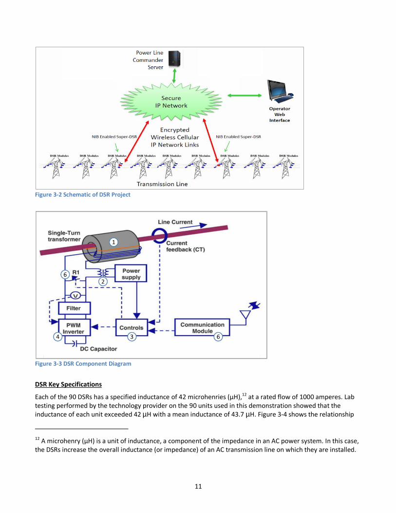
Figure 3-2 Schematic of DSR Project
Figure 3-3 DSR Component Diagram
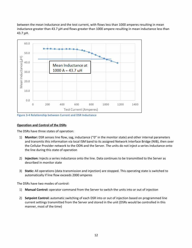
DSR Key Specifications
Each of the 90 DSRs has a specified inductance of 42 microhenries (µH),12 at a rated flow of 1000 amperes. Lab testing performed by the technology provider on the 90 units used in this demonstration showed that the inductance of each unit exceeded 42 µH with a mean inductance of 43.7 µH. Figure 3-4 shows the relationship
12 A microhenry (µH) is a unit of inductance, a component of the impedance in an AC power system. In this case, the DSRs increase the overall inductance (or impedance) of an AC transmission line on which they are installed.
12
between the mean inductance and the test current, with flows less than 1000 amperes resulting in mean inductance greater than 43.7 µH and flows greater than 1000 ampere resulting in mean inductance less than 43.7 µH.
Figure 3-4 Relationship between Current and DSR Inductance
Operation and Control of the DSRs
The DSRs have three states of operation:
1) Monitor: DSR senses line flow, sag, inductance (“0” in the monitor state) and other internal parameters and transmits this information via local ISM band to its assigned Network Interface Bridge (NIB), then over the Cellular Provider network to the ODN and the Server. The units do not inject a series inductance onto the line during this state of operation
2) Injection: Injects a series inductance onto the line. Data continues to be transmitted to the Server as described in monitor state
3) Static: All operations (data transmission and injection) are stopped. This operating state is switched to automatically if line flow exceeds 2000 amperes
The DSRs have two modes of control:
1) Manual Control: operator command from the Server to switch the units into or out of injection
2) Setpoint Control: automatic switching of each DSR into or out of injection based on programmed line current settings transmitted from the Server and stored in the unit (DSRs would be controlled in this manner, most of the time)
13
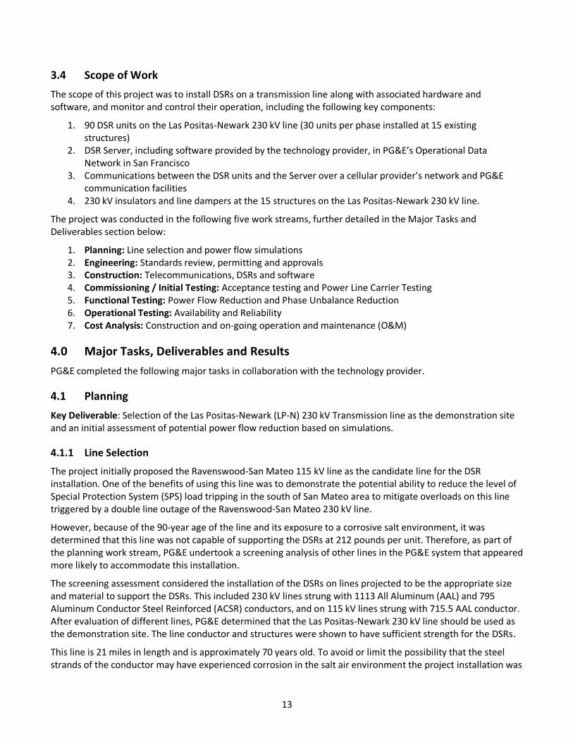
Scope of Work 3.4
The scope of this project was to install DSRs on a transmission line along with associated hardware and software, and monitor and control their operation, including the following key components:
1. 90 DSR units on the Las Positas-Newark 230 kV line (30 units per phase installed at 15 existing structures)
2. DSR Server, including software provided by the technology provider, in PG&E’s Operational Data Network in San Francisco
3. Communications between the DSR units and the Server over a cellular provider’s network and PG&E communication facilities
4. 230 kV insulators and line dampers at the 15 structures on the Las Positas-Newark 230 kV line.
The project was conducted in the following five work streams, further detailed in the Major Tasks and Deliverables section below:
1. Planning: Line selection and power flow simulations 2. Engineering: Standards review, permitting and approvals 3. Construction: Telecommunications, DSRs and software 4. Commissioning / Initial Testing: Acceptance testing and Power Line Carrier Testing 5. Functional Testing: Power Flow Reduction and Phase Unbalance Reduction 6. Operational Testing: Availability and Reliability 7. Cost Analysis: Construction and on-going operation and maintenance (O&M)
4.0 Major Tasks, Deliverables and Results
PG&E completed the following major tasks in collaboration with the technology provider.
Planning 4.1
Key Deliverable: Selection of the Las Positas-Newark (LP-N) 230 kV Transmission line as the demonstration site and an initial assessment of potential power flow reduction based on simulations.
Line Selection 4.1.1
The project initially proposed the Ravenswood-San Mateo 115 kV line as the candidate line for the DSR installation. One of the benefits of using this line was to demonstrate the potential ability to reduce the level of Special Protection System (SPS) load tripping in the south of San Mateo area to mitigate overloads on this line triggered by a double line outage of the Ravenswood-San Mateo 230 kV line.
However, because of the 90-year age of the line and its exposure to a corrosive salt environment, it was determined that this line was not capable of supporting the DSRs at 212 pounds per unit. Therefore, as part of the planning work stream, PG&E undertook a screening analysis of other lines in the PG&E system that appeared more likely to accommodate this installation.
The screening assessment considered the installation of the DSRs on lines projected to be the appropriate size and material to support the DSRs. This included 230 kV lines strung with 1113 All Aluminum (AAL) and 795 Aluminum Conductor Steel Reinforced (ACSR) conductors, and on 115 kV lines strung with 715.5 AAL conductor. After evaluation of different lines, PG&E determined that the Las Positas-Newark 230 kV line should be used as the demonstration site. The line conductor and structures were shown to have sufficient strength for the DSRs.
This line is 21 miles in length and is approximately 70 years old. To avoid or limit the possibility that the steel strands of the conductor may have experienced corrosion in the salt air environment the project installation was
14
undertaken on the portion of the line in the drier, warmer Sunol-Livermore area instead of the portion in the Newark Area, which is adjacent to the San Francisco Bay salt air.
Power Flow Simulations 4.1.2
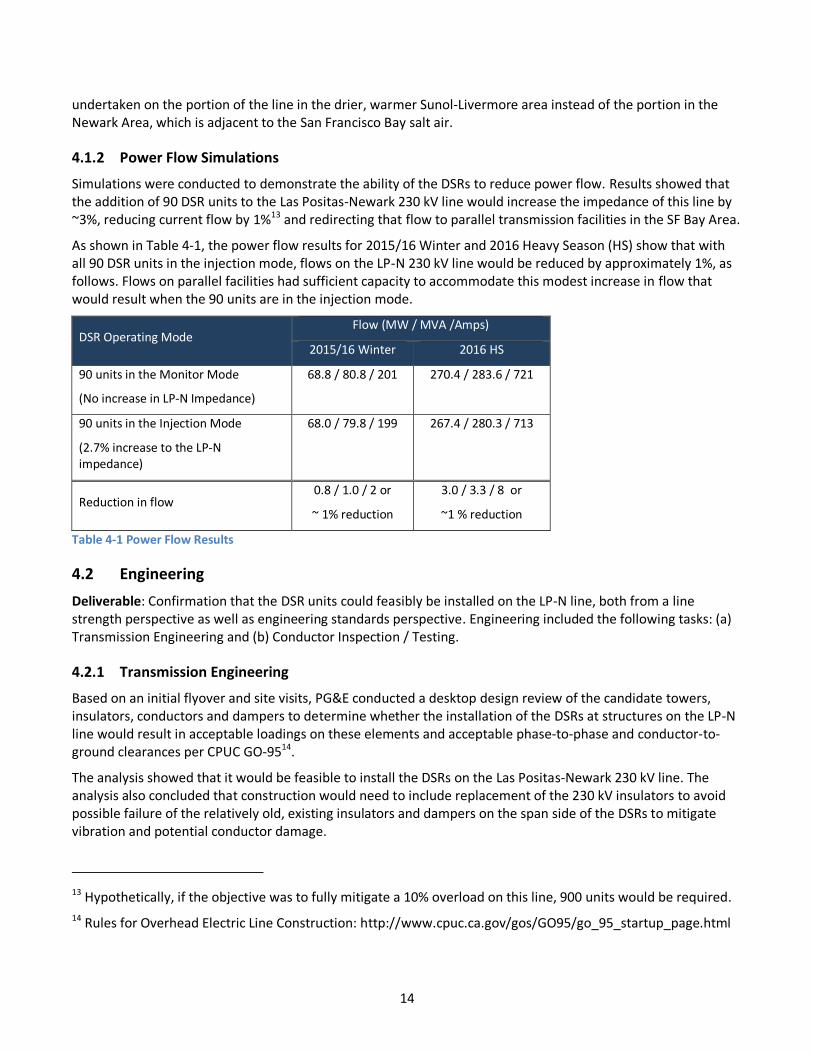
Simulations were conducted to demonstrate the ability of the DSRs to reduce power flow. Results showed that the addition of 90 DSR units to the Las Positas-Newark 230 kV line would increase the impedance of this line by ~3%, reducing current flow by 1%13 and redirecting that flow to parallel transmission facilities in the SF Bay Area.
As shown in Table 4-1, the power flow results for 2015/16 Winter and 2016 Heavy Season (HS) show that with all 90 DSR units in the injection mode, flows on the LP-N 230 kV line would be reduced by approximately 1%, as follows. Flows on parallel facilities had sufficient capacity to accommodate this modest increase in flow that would result when the 90 units are in the injection mode.
DSR Operating Mode Flow (MW / MVA /Amps)
2015/16 Winter 2016 HS
90 units in the Monitor Mode
(No increase in LP-N Impedance)
68.8 / 80.8 / 201 270.4 / 283.6 / 721
90 units in the Injection Mode
(2.7% increase to the LP-N impedance)
68.0 / 79.8 / 199 267.4 / 280.3 / 713
Reduction in flow 0.8 / 1.0 / 2 or
~ 1% reduction
3.0 / 3.3 / 8 or
~1 % reduction
Table 4-1 Power Flow Results
Engineering 4.2
Deliverable: Confirmation that the DSR units could feasibly be installed on the LP-N line, both from a line strength perspective as well as engineering standards perspective. Engineering included the following tasks: (a) Transmission Engineering and (b) Conductor Inspection / Testing.
Transmission Engineering 4.2.1
Based on an initial flyover and site visits, PG&E conducted a desktop design review of the candidate towers, insulators, conductors and dampers to determine whether the installation of the DSRs at structures on the LP-N line would result in acceptable loadings on these elements and acceptable phase-to-phase and conductor-to-ground clearances per CPUC GO-9514.
The analysis showed that it would be feasible to install the DSRs on the Las Positas-Newark 230 kV line. The analysis also concluded that construction would need to include replacement of the 230 kV insulators to avoid possible failure of the relatively old, existing insulators and dampers on the span side of the DSRs to mitigate vibration and potential conductor damage.
13 Hypothetically, if the objective was to fully mitigate a 10% overload on this line, 900 units would be required.
14 Rules for Overhead Electric Line Construction: http://www.cpuc.ca.gov/gos/GO95/go_95_startup_page.html
15
Conductor Testing / Inspection 4.2.2
Given its 70-year age, the 795 ACSR conductor was tested to determine its tensile strength and the extent to which there was any corrosion to the steel strands to ensure it was fit to support the DSRs. Two samples from conductors in the Sunol-Livermore area were removed and sent to PG&E’s Applied Technology Services for testing. Testing showed that the samples had retained 100% of the original specification tensile strength.
Construction 4.3
Deliverable: Installation of 90 DSR units and associated telecommunication and software system. Construction consisted of (a) DSR unit installation and (b) telecommunications / software installation.
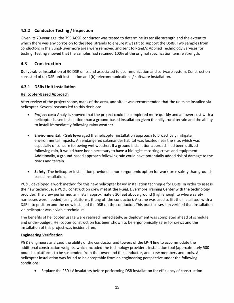
DSRs Unit Installation 4.3.1
Helicopter-Based Approach
After review of the project scope, maps of the area, and site it was recommended that the units be installed via helicopter. Several reasons led to this decision:
Project cost: Analysis showed that the project could be completed more quickly and at lower cost with a helicopter-based installation than a ground-based installation given the hilly, rural terrain and the ability to install immediately following rainy weather.
Environmental: PG&E leveraged the helicopter installation approach to proactively mitigate environmental impacts. An endangered salamander habitat was located near the site, which was especially of concern following wet weather. If a ground installation approach had been utilized following rain, it would have been necessary to have a biologist escorting crews and equipment. Additionally, a ground-based approach following rain could have potentially added risk of damage to the roads and terrain.
Safety: The helicopter installation provided a more ergonomic option for workforce safety than ground-based installation.
PG&E developed a work method for this new helicopter based installation technique for DSRs. In order to assess the new technique, a PG&E construction crew met at the PG&E Livermore Training Center with the technology provider. The crew performed an install approximately 30 feet above ground (high enough to where safety harnesses were needed) using platforms (hung off the conductor). A crane was used to lift the install tool with a DSR into position and the crew installed the DSR on the conductor. This practice session verified that installation via helicopter was a viable technique.
The benefits of helicopter usage were realized immediately, as deployment was completed ahead of schedule and under-budget. Helicopter construction has been shown to be ergonomically safer for crews and the installation of this project was incident-free.
Engineering Verification
PG&E engineers analyzed the ability of the conductor and towers of the LP-N line to accommodate the additional construction weights, which included the technology provider’s installation tool (approximately 500 pounds), platforms to be suspended from the tower and the conductor, and crew members and tools. A helicopter installation was found to be acceptable from an engineering perspective under the following conditions:
Replace the 230 kV insulators before performing DSR installation for efficiency of construction
16
For safety purposes, use only one 2-man crew on the platform with tools, install tool and DSR per span per tower, while other crew members to remain on the tower during installation
Installation Tool
In addition to development of new helicopter work methods and verification of feasibility from an engineering perspective, PG&E collaborated with the vendor to improve and redesign the DSR installation tool. The original tool was designed to hang on the side of a bucket. The crew member would ride up in the bucket with the install tool containing a DSR hanging on the outside of the bucket. This presented potential safety concerns. Instead, the tool was modified with the addition of an eye hook (and the removal of the components that allowed it to hang on the bucket). The eye hook provided a means for the install tool to be used with a cable suspended from a crane (for a ground based installation) or from a cable connected to a helicopter (air-based).
Construction and Work Methods
Three landing zones were identified from where construction would be performed, and on which equipment needed for the day’s work would be stored. Owners of these sites were notified and arrangements were made to utilize the landing zones. Prior to construction a permit was obtained from the City and County of San Francisco to access a landing zone and the three structures on their property.
The work method for installing the DSRs consisted of:
Helicopter transports the crew (including safety equipment and hand tools), ladders, and platform (platform is bolted to the bottom of the ladder) from the landing zone to the tower.
Ladder is hung from the tower cross-arm and the far end of the platform is suspended from the conductor.
Helicopter then transports a DSR mounted in the installation tool to the tower
Working on the platform, the crew clamps the installation tool to the conductor
Helicopter cable is released from the installation tool
Crew cranks the upper and lower halves of the DSR around the conductor, and bolts the two halves together
Helicopter returns to the platform, the crew connects the helicopter cable to the installation tool and releases the installation tool from the conductor
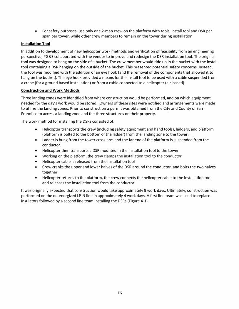
It was originally expected that construction would take approximately 9 work days. Ultimately, construction was performed on the de-energized LP-N line in approximately 4 work days. A first line team was used to replace insulators followed by a second line team installing the DSRs (Figure 4-1).
17
Figure 4-1 Tower on Las Positas-Newark 230 kV line with 6 units installed and Crew Installing Unit
Telecommunications / Software Installation 4.3.2
Prior to construction, PG&E conducted a review of firewalls and cyber security. It was concluded that security was sufficient for this specific demonstration and location. However, while cyber security was accounted for within the demonstration, it is unknown whether cellular service would meet all NERC CIP requirements for future, production level projects as it is not utility-controlled. Further evaluation would be required for potential future installations to ensure Critical Infrastructure Protection (CIP) requirements are met at each site.
Telecommunications engineering and installation included the following key activities:
1. Establishing Cellular Communication: Requested that the cellular provider established communications between Network Interface Bridges (NIBs) housed in select demonstration DSRs dispersed along the transmission line and PG&E’s Fairfield Information Operations Center (FFIOC) and the San Francisco IOC (SFIOC)
2. Server Installation: Procured the DSR Server and installed it within PG&E’s Operational Data Network (ODN)
3. Communications: Established communications between the Server and PG&E’s EMS. Implemented firewall exceptions to enable monitoring and control of the units from the Server.
4. Testing: Performed an end-to-end communications test between the server and the NIBs to ensure there was a continuous communications path.
During initial testing, commands from the Server were taking too long (up to 5 minutes) to implement due primarily to the fact that NIBs were connected to up to 18-24 units. PG&E believed this latency to be unacceptable for the demonstration. As such, an additional 8 NIBs were activated so that each NIB was connected to 6 units at each of the 15 structures. This significantly reduced the latency.
18
Commissioning/Initial Testing 4.4
Deliverable: Initial verification that the DSRs can communicate without impact to primary fault protection communication systems and can produce inductance as specified. Commissioning/initial testing consisted of the following tasks: (a) Acceptance Testing, and (b) Power Line Carrier Protection Testing.
Acceptance Testing 4.4.1
This test verified that there was end-to-end communication between the DSR server in San Francisco and each unit and that each unit produced an inductance of at least 42 µH per specification. Operators manually switched 6 DSR units (2 units per phase) into injection mode and recorded the inductance provided by each units using the DSR web interface. Based on power flow studies, switching of 6 DSR units into the injection mode would reduce flow on the Las Positas-Newark 230 kV line by less than .1% (6/90 * 1.1% = .07%). This test was conducted in under 8 hours. At the conclusion of the test, all units were switched back to monitor mode.
Acceptance Testing Results
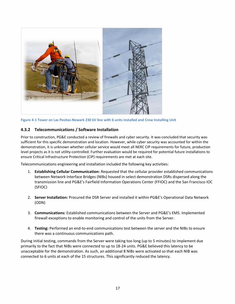
Results showed that this specification was met and exceeded with an inductance of 53 µH per unit. As an example, Figure 4-2 shows that 6 units (2 per phase) at Tower 23 were confirmed switched to injection (red circle) as directed by the operator.
Figure 4-2 DSR State with 6 Units in Injection
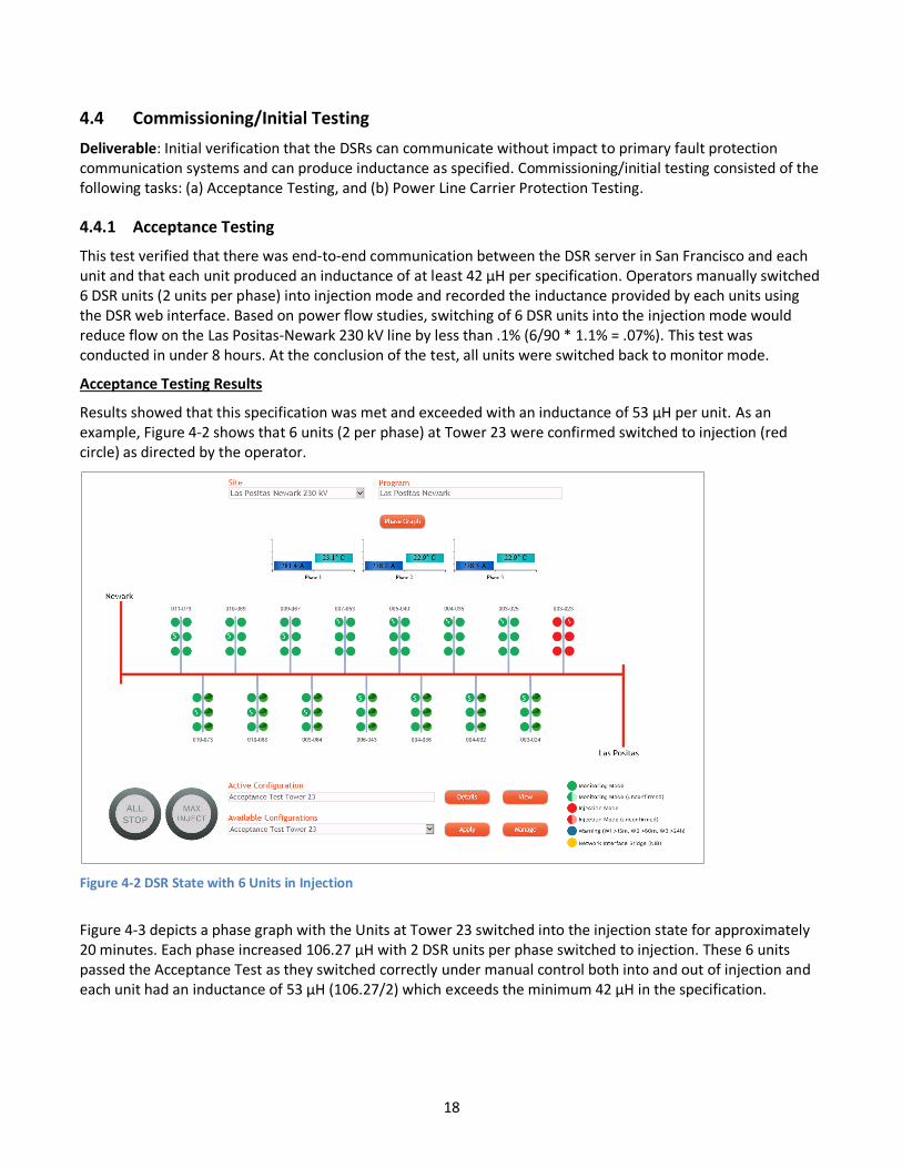
Figure 4-3 depicts a phase graph with the Units at Tower 23 switched into the injection state for approximately 20 minutes. Each phase increased 106.27 µH with 2 DSR units per phase switched to injection. These 6 units passed the Acceptance Test as they switched correctly under manual control both into and out of injection and each unit had an inductance of 53 µH (106.27/2) which exceeds the minimum 42 µH in the specification.
19
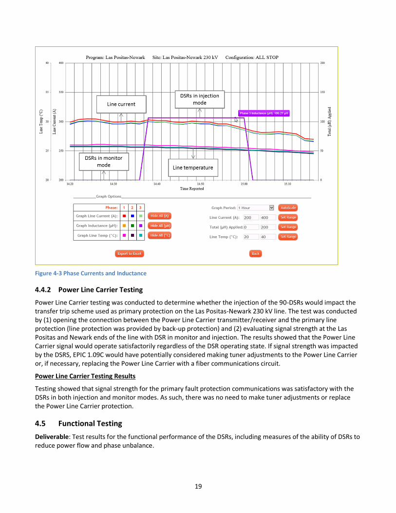
Figure 4-3 Phase Currents and Inductance
Power Line Carrier Testing 4.4.2
Power Line Carrier testing was conducted to determine whether the injection of the 90-DSRs would impact the transfer trip scheme used as primary protection on the Las Positas-Newark 230 kV line. The test was conducted by (1) opening the connection between the Power Line Carrier transmitter/receiver and the primary line protection (line protection was provided by back-up protection) and (2) evaluating signal strength at the Las Positas and Newark ends of the line with DSR in monitor and injection. The results showed that the Power Line Carrier signal would operate satisfactorily regardless of the DSR operating state. If signal strength was impacted by the DSRS, EPIC 1.09C would have potentially considered making tuner adjustments to the Power Line Carrier or, if necessary, replacing the Power Line Carrier with a fiber communications circuit.
Power Line Carrier Testing Results
Testing showed that signal strength for the primary fault protection communications was satisfactory with the DSRs in both injection and monitor modes. As such, there was no need to make tuner adjustments or replace the Power Line Carrier protection.
Functional Testing 4.5
Deliverable: Test results for the functional performance of the DSRs, including measures of the ability of DSRs to reduce power flow and phase unbalance.

20
Power Flow Control 4.5.1
Tests were conducted to demonstrate the ability of the DSRs to impact current flow on the LP-N line under both manual and set-point control. Analysis was conducted leveraging the DSR software and verified in PG&E’s Supervisory Control and Data Acquisition system (SCADA)15.
Power Flow Control Results
As demonstrated in Figure 4-4, switching the units to injection state (All Inject) decreases flow by 1-2%, and switching flow out of injection state (All Stop) increases flow by 1-2%. The inductance of each unit with flows in the 225-250 ampere range was about 53 µH, 25% higher than the specified 42 µH at 1000 amperes. The immediate change in the seconds after switching modes was consistent and can be attributed to the DSRs. Fluctuations in current flow while the units are in either operating state are due to changes in system load or generation.
Figure 4-4 Current & Inductance in Manual Control
15 SCADA is used to monitor and control a plan, a substation, or other utility installations. It is combination of telemetry and data acquisition and consists of collecting information, transferring it back to a central site, carrying out necessary analysis and control, and then displaying this data on a number of operator screens. http://www.pge.com/includes/docs/pdfs/shared/rates/tariffbook/ferc/tih/gloss.pdf.
21
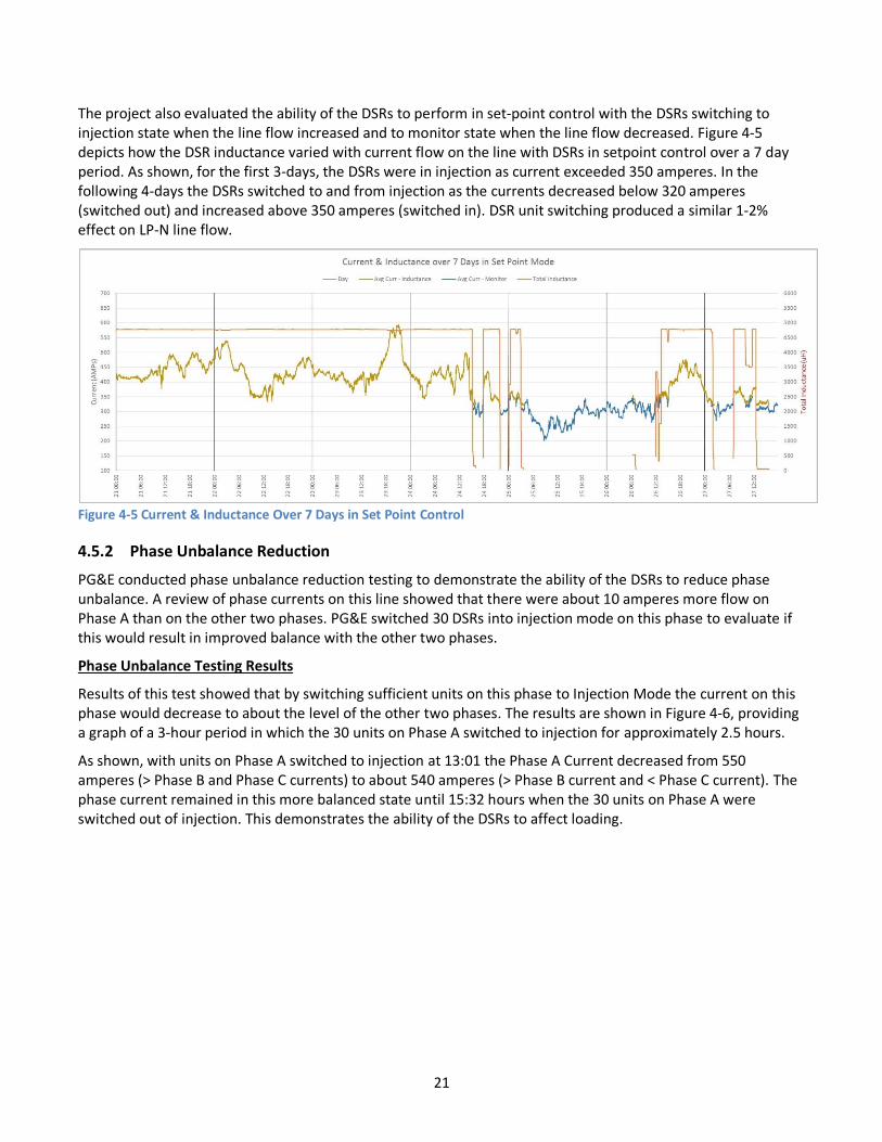
The project also evaluated the ability of the DSRs to perform in set-point control with the DSRs switching to injection state when the line flow increased and to monitor state when the line flow decreased. Figure 4-5 depicts how the DSR inductance varied with current flow on the line with DSRs in setpoint control over a 7 day period. As shown, for the first 3-days, the DSRs were in injection as current exceeded 350 amperes. In the following 4-days the DSRs switched to and from injection as the currents decreased below 320 amperes (switched out) and increased above 350 amperes (switched in). DSR unit switching produced a similar 1-2% effect on LP-N line flow.
Figure 4-5 Current & Inductance Over 7 Days in Set Point Control
Phase Unbalance Reduction 4.5.2
PG&E conducted phase unbalance reduction testing to demonstrate the ability of the DSRs to reduce phase unbalance. A review of phase currents on this line showed that there were about 10 amperes more flow on Phase A than on the other two phases. PG&E switched 30 DSRs into injection mode on this phase to evaluate if this would result in improved balance with the other two phases.
Phase Unbalance Testing Results
Results of this test showed that by switching sufficient units on this phase to Injection Mode the current on this phase would decrease to about the level of the other two phases. The results are shown in Figure 4-6, providing a graph of a 3-hour period in which the 30 units on Phase A switched to injection for approximately 2.5 hours.
As shown, with units on Phase A switched to injection at 13:01 the Phase A Current decreased from 550 amperes (> Phase B and Phase C currents) to about 540 amperes (> Phase B current and < Phase C current). The phase current remained in this more balanced state until 15:32 hours when the 30 units on Phase A were switched out of injection. This demonstrates the ability of the DSRs to affect loading.

22
Figure 4-6 Phase Currents with DSRs on Phase A Only Injecting
Operational Testing 4.6
Deliverable: Test results for operational measures, including availability and reliability of the units.
PG&E tested key operational measures, including availability and reliability of the units. The DSRs were monitored for a 6-month period covering warm weather and summer peak conditions. During this period, units were generally operated under set-point control (DSRs switched into and out of injection based on stored current settings) though there were periods when the units were operated under manual control (DSRs switched into and out of injection via a command from the server). During this period data from each DSR unit was transferred about every 10-15 seconds to the server for storage and off-line analysis was conducted to assess operating performance.
Availability 4.6.1
Availability testing measured the percentage of time the DSR units were communicating with no more than a 60 second lag between successive scans. This metric excluded the time when the Las Positas-Newark 230 kV line was scheduled out of service for planned maintenance. The target for the availability metric was 98%. This number was chosen as a baseline for the demonstration, to represent a potentially tolerable level of availability and could provide an indication of additional investment in DSRs (2% above needed amount) to cover for the units that might be unavailable.
Availability Testing Results
The Availability Metric provides the percentage of time units were communicating with no more than a 60 second lag between successive scans.
23
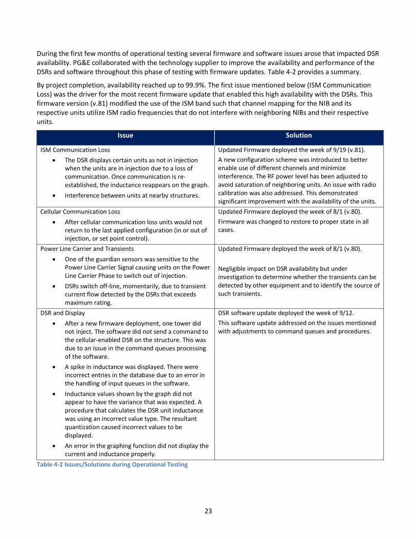
During the first few months of operational testing several firmware and software issues arose that impacted DSR availability. PG&E collaborated with the technology supplier to improve the availability and performance of the DSRs and software throughout this phase of testing with firmware updates. Table 4-2 provides a summary.
By project completion, availability reached up to 99.9%. The first issue mentioned below (ISM Communication Loss) was the driver for the most recent firmware update that enabled this high availability with the DSRs. This firmware version (v.81) modified the use of the ISM band such that channel mapping for the NIB and its respective units utilize ISM radio frequencies that do not interfere with neighboring NIBs and their respective units.
Issue Solution
ISM Communication Loss
The DSR displays certain units as not in injection when the units are in injection due to a loss of communication. Once communication is re-established, the inductance reappears on the graph.
Interference between units at nearby structures.
Updated Firmware deployed the week of 9/19 (v.81).
A new configuration scheme was introduced to better enable use of different channels and minimize interference. The RF power level has been adjusted to avoid saturation of neighboring units. An issue with radio calibration was also addressed. This demonstrated significant improvement with the availability of the units.
Cellular Communication Loss
After cellular communication loss units would not return to the last applied configuration (in or out of injection, or set point control).
Updated Firmware deployed the week of 8/1 (v.80).
Firmware was changed to restore to proper state in all cases.
Power Line Carrier and Transients
One of the guardian sensors was sensitive to the Power Line Carrier Signal causing units on the Power Line Carrier Phase to switch out of injection.
DSRs switch off-line, momentarily, due to transient current flow detected by the DSRs that exceeds maximum rating.
Updated Firmware deployed the week of 8/1 (v.80).
Negligible impact on DSR availability but under investigation to determine whether the transients can be detected by other equipment and to identify the source of such transients.
DSR and Display
After a new firmware deployment, one tower did not inject. The software did not send a command to the cellular-enabled DSR on the structure. This was due to an issue in the command queues processing of the software.
A spike in inductance was displayed. There were incorrect entries in the database due to an error in the handling of input queues in the software.
Inductance values shown by the graph did not appear to have the variance that was expected. A procedure that calculates the DSR unit inductance was using an incorrect value type. The resultant quantization caused incorrect values to be displayed.
An error in the graphing function did not display the current and inductance properly.
DSR software update deployed the week of 9/12.
This software update addressed on the issues mentioned with adjustments to command queues and procedures.
Table 4-2 Issues/Solutions during Operational Testing

24
Table 4-3 and Figure 4-7 below present the results from May 30-November 13 2016. As indicated, the implementation of firmware version 6.12.81 improved availability significantly to over 99.5% on a weekly basis.
Week Starting
Availability Firmware Version
Week Starting
Availability Firmware Version
5/30 98.75% 6.12.76 8/22 97.73% 6.12.80
6/6 98.75% 6.12.76 8/29 97.50% 6.12.80
6/13 98.89% 6.12.76 9/5 97.70% 6.12.80
6/20 98.23% 6.12.78 9/12 96.36% 6.12.80
6/27 98.01% 6.12.78 9/19 98.36% 80-81
7/4 97.52% 6.12.78 9/26 99.45% 6.12.81
7/11 97.26% 6.12.78 10/3 99.96% 6.12.81
7/18 97.67% 6.12.78 10/10 99.96% 6.12.81
7/25 97.47% 6.12.78 10/17 99.91% 6.12.81
8/1 97.39% 78,79,80 10/24 99.95% 6.12.81
8/8 98.07% 6.12.80 10/31 99.94% 6.12.81
8/15 97.76% 6.12.80 11/7 99.90% 6.12.81
Table 4-3 Percent Availability of the DSRs by Week
Figure 4-7 Percent Availability of DSRs by Week
While overall availability is high, results also indicated that when a time gap >1 minute is experienced, a number of units would lose communication simultaneously. During such gaps, the units are not sending data back to the server and would not respond to commands to switch into or out of injection. The results showed that the system experienced no time gaps > 1 minute 98% of the time. Installing additional units beyond the 90 units would restore to the net availability (total installed minus the number potentially not visible to the DSR Server and the operators) to 100%. The project did not install the additional units since availability met specification. However, PG&E will explore the possibility of installation of additional units to address possible simultaneous unavailability of DSRs as needed.
25
Reliability 4.6.2
Reliability testing evaluated the percentage of time that available units were in the correct operating state (injection or monitor). This analysis was conducted during the final firmware version v.81.
Reliability Testing Results
Analysis showed that for version v.81, the DSRs were in the correct operating state 99.99% of the time.
Cost Review 4.7
PG&E conducted a review of both construction and operation and maintenance (O&M) costs of the DSRs.
Construction Costs: Analysis showed that thermal overloading of another PG&E 230kV line could be mitigated by (a) reconductoring at an estimated cost of approximately $130 million, or (b) installing approximately 2000 DSR units on this line at an estimated cost of approximately $33 million—25% of the cost of reconductoring. DSRs were considered a feasible alternative for this situation. However, based on the latest transmission planning study results, the need for the project is being reconsidered in light of significantly lower thermal overloads due to lower load forecasts resulting from increased levels of forecasted Distributed Energy Resources and energy efficiency.
On-Going O&M Costs: On-going O&M costs are estimated to be relatively low for annual software licensing for the control and monitoring, operating system updates, and cellular fees for data transfer (e.g., for 90 DSRs this cost is ~$5000).
5.0 Summary of Learnings and Next Steps
PG&E produced several learnings and next steps to be explored with regards to DSRs. Learnings have been categorized as related to planning/engineering/construction, telecommunications, or functional.
Planning, engineering and construction of the DSRs produced the following learnings, and as such PG&E will explore the following next steps for any new potential installations:

26
Planning, Engineering & Construction Learnings Next Steps
Early planning and engineering is required for site selection, as not all sites are suitable for DSRs: Concerns with the initially selected conductor’s strength underscore the importance of early engineering involvement to evaluate the feasibility of the project and determine which deployment method is most appropriate. DSRs cannot be installed on any transmission line. A proposed line needs to have sufficient conductor and tower strength capable of supporting the DSR devices. This could reduce their use on smaller lines or lines along the coast subject to corrosive salt spray.
Address engineering and deployment requirements early on: With any new potential installation, PG&E will address engineering as a key early component of the project. This process must include formal tower inspections as part of the engineering drawing development to as a key task to inform site selection of the DSRs. PG&E will explore potential development of new design standards for the installation considering construction and post construction loads placed on conductor and structures consistent with CPUC requirements
16.
Additionally, California Independent System Operator (CAISO) approval is required for any potential future installations in order to leverage the DSR technology for mitigation of transmission overloads.
Remote identifiability of deployed units: In this project, with testing and evaluation of results, the project team had the required clarity about the location of individual units. However, based on operator feedback, identification faceplates readable from the air and ground should be utilized in any future larger-scale installation to enable users to have more clarity and confidence in the location of individual units and the overall configuration of the DSR project.
Install identification nameplates on future DSR installations: PG&E plans to explore the use of identification nameplates with any future potential DSR (or next generation DSR) installations.
The installation of DSRs was efficient overall: The project leveraged an advanced line team to replace insulators followed by a second line team installing the DSRs for an efficient and simplified deployment on a de-energized line.
Investigate transition to energized installations: With the success of this deployment, line engineers have suggested exploring the possibility of energized line installations for future projects.
16 NERC Reliability Standards: http://www.nerc.com/pa/stand/Pages/ReliabilityStandardsUnitedStates.aspx?jurisdiction=United%20States.
27
Helicopters can successfully be leveraged for DSR installation: PG&E developed new helicopter-based work methods for installation of the DSRs instead of land-based construction using cranes and bucket trucks. The benefits of helicopter usage were realized immediately, as deployment was completed ahead of schedule and under-budget, while avoiding environmental damage to the terrain from heavy ground-based equipment and potential impacts to tiger salamanders following rainy weather. Helicopter construction has been shown to be ergonomically safer for crews and the installation of this project was incident-free.
Close coordination with local land owners was critical to the success of this approach. Additionally, it was found to be important to plan for lead times associated with county / city permitting and land access.
The improved DSR installation tool developed in this project in collaboration with the technology provider enabled this air-based approach (in addition to ground based installation). The original tool was designed to hang on the side of a bucket. Instead, the tool was modified with the addition of an eye hook (and the removal of the components that allowed it to hang on the bucket). The eye hook provided a means for the install tool to be used with a cable suspended from a crane or from a cable connected to a helicopter.
Explore use of new helicopter installation work methods in future projects: For any new potential installations, PG&E will explore the use of this helicopter-based work method as appropriate. Additionally, PG&E will ensure close coordination with land owners and advanced planning for necessary permitting.
Table 5-1 Planning, Engineering and Construction Learnings
Telecommunications planning and installation for the DSRs produced the following learnings, and as such PG&E will explore the following next steps for any new potential installations:
Telecommunications Learnings Next Step
Cyber security review is a critical component of DSR installation: Prior to the demonstration deployment, PG&E conducted a review of firewalls and cyber security. It was concluded that security was sufficient for this specific demonstration and location. However, while cyber security was accounted for within the demonstration, it is unknown whether cellular service would meet all NERC CIP requirements for future, production level projects as it is not utility-controlled. Further evaluation would be required for potential future installations to ensure Critical Infrastructure Protection (CIP) requirements are met at each site.
Cyber security reviews: Prior to any potential new DSR installation, a cyber security review should be conducted to ensure CIP requirements are met at the specific install location. Consideration will be given to leveraging utility controlled fiber or microwave as an alternate communication path.

28
The number of NIBs impacts communication latency of commands: During initial testing, commands from the Server were taking too long (up to 5 minutes) to implement due primarily to the fact that NIBs were connected to up to 18-24 units. PG&E believed this latency to be unacceptable for the demonstration. As such, an additional 8 NIBs were activated so that each NIB was connected to 6 units at each of the 15 structures. This significantly reduced the latency.
Include impact of latency in establishing of the number of NIBs: In a potential production project, units would likely operate in set-point control most of the time. However, there can be situations in which the operator might be required to issue an emergency command from the server. As such, for any future potential DSR (or next generation technology) deployments, PG&E will consider this learning in order to establish an appropriate number of NIBs to manage latency.
Table 5-2 Telecommunication Learnings
PG&E produced the following functional learnings related to DSRs in an operational environment, and as such PG&E will explore the following next steps:
Functional Learnings Next Step
DSRs can successfully reduce line flow and phase unbalance in an operational environment, but the effect is incremental: Demonstration results showed that the DSRs can produce inductance of over 42 µH, reduce line flow, and improve the balance of power flow on the three phases of the line. By project completion, the results showed 99.9% availability. Additionally, the analysis showed that the DSRs were in the correct operating state 99.99% of the time.
While the technology was successfully demonstrated in an operational environment, line flow reduction was incremental. As such, a much larger number of units than the 90 units in this project will be required to reduce or eliminate most transmission overloads. Such overloads are identified as part of power flow analyses that are performed annually and alternatives are evaluated as mitigation. This demonstration project shows that even if an increase in the amount of units is needed, that deployment of DSRs, if feasible, would still be significantly less costly than a traditional transmission upgrade to increase capacity in most scenarios.
Leverage continually advancing DSR technology: The technology provider is developing a new technology that is expected to provide an even greater reduction in line flow while leveraging the same DSR firmware and software. With demonstrated results in reduction of line flow, as well as high availability and reliability, PG&E will explore potential future opportunities for this advancing technology, and plans to work with the provider to leverage the DSR installation on the Las Positas-Newark 230 kV line as a test bed for evaluating planned firmware and software upgrades.
PG&E is currently considering the next generation DSR technology as a potential solution for an additional line. With each overload situation, the advancing DSR technology will be considered a viable option to be evaluated for costs and benefits alongside traditional mitigation strategies.
Table 5-3 Functional Learnings
6.0 Data Access
Upon request, PG&E will provide access to data collected that is consistent with the CPUC's data access requirements for EPIC data and results.
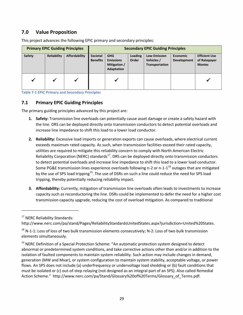
29
7.0 Value Proposition
This project advances the following EPIC primary and secondary principles:
Primary EPIC Guiding Principles Secondary EPIC Guiding Principles
Safety Reliability Affordability Societal Benefits
GHG Emissions Mitigation / Adaptation
Loading Order
Low-Emission Vehicles / Transportation
Economic Development
Efficient Use of Ratepayer Monies
Table 7-1 EPIC Primary and Secondary Principles
Primary EPIC Guiding Principles 7.1
The primary guiding principles advanced by this project are:
1. Safety: Transmission line overloads can potentially cause asset damage or create a safety hazard with
the line. DRS can be deployed directly onto transmission conductors to detect potential overloads and
increase line impedance to shift this load to a lower load conductor.
2. Reliability: Excessive load imports or generation exports can cause overloads, where electrical current
exceeds maximum rated capacity. As such, when transmission facilities exceed their rated capacity,
utilities are required to mitigate this reliability concern to comply with North American Electric
Reliability Corporation (NERC) standards17. DRS can be deployed directly onto transmission conductors
to detect potential overloads and increase line impedance to shift this load to a lower load conductor.
Some PG&E transmission lines experience overloads following n-2 or n-1-118 outages that are mitigated
by the use of SPS load tripping19. The use of DSRs on such a line could reduce the need for SPS load
tripping, thereby potentially reducing reliability impact.
3. Affordability: Currently, mitigation of transmission line overloads often leads to investments to increase
capacity such as reconductoring the line. DSRs could be implemented to defer the need for a higher cost
transmission capacity upgrade, reducing the cost of overload mitigation. As compared to traditional
17 NERC Reliability Standards: http://www.nerc.com/pa/stand/Pages/ReliabilityStandardsUnitedStates.aspx?jurisdiction=United%20States.
18 N-1-1: Loss of loss of two bulk transmission elements consecutively; N-2: Loss of two bulk transmission elements simultaneously.
19 NERC Definition of a Special Protection Scheme: “An automatic protection system designed to detect abnormal or predetermined system conditions, and take corrective actions other than and/or in addition to the isolation of faulted components to maintain system reliability. Such action may include changes in demand, generation (MW and Mvar), or system configuration to maintain system stability, acceptable voltage, or power flows. An SPS does not include (a) underfrequency or undervoltage load shedding or (b) fault conditions that must be isolated or (c) out-of-step relaying (not designed as an integral part of an SPS). Also called Remedial Action Scheme.” http://www.nerc.com/pa/Stand/Glossary%20of%20Terms/Glossary_of_Terms.pdf.
30
transmission investments, DSRs can be deployed several years faster at a significantly lesser cost.
Additionally, DSRs offer portability and flexibility. Traditional upgrades are permanent installations.
Conversely, DSRs could be installed to eliminate the temporary overload and relocated to another
location when that overload condition disappears. DSRs could also be used to provide transmission
congestion relief allowing greater access to potentially lower cost generation resources.
Secondary Principles of EPIC 7.2
The secondary guiding principles advanced by this project are:
1. Greenhouse gas (GHG) emissions reduction: DSRs could be leveraged to provide transmission
congestion relief. This could potentially enable greater access to renewable resources, which
contributes to GHG emissions reduction.
2. Efficient use of ratepayer monies: DSRs are an innovative technology that would allow more efficient use of the transmission system by redirecting power flow from overloaded facilities to facilities with available capacity. As such, these devices can be used to reduce operating costs and defer higher cost transmission line projects.
8.0 Technology Transfer Plan
PG&E’s Technology Transfer Plans 8.1
A primary benefit of the EPIC program is the technology and knowledge sharing that occurs both internally within PG&E, and across the other IOUs, the CEC and the industry. To facilitate this knowledge sharing, PG&E has shared the results of this project through public reports published on the PG&E website and in the following meetings and phone discussions:
CAISO Presentations – Folsom, CA
March 27, 2014
August 13, 2014
January 4, 2016
Utility Presentations and Sharing
SCE and SDG&E, May 22, 2014
SDG&E April 5, 2016
Bonneville Power Administration September 21, 2016
Arizona Public Service October 3, 2016
In the comings months, PG&E will continue exploring industry outreach in order to share project learnings and discuss future potential opportunities.
Adaptability to Other Utilities / Industry 8.2
Utilities are required to mitigate transmission line overloads to comply with North American Electric Reliability Corporation (NERC) standards. This demonstrations project shows that use of DSRs can be considered as an alternative to more costly upgrades such as new transmission lines or reconductoring existing lines.
As demonstrated in this project, DSRs are capable of reducing power flow and phase unbalance. This could be applied to improve upon a number of common utility challenges and opportunities, such as:

31
Providing a cost effective solution with the ability to reduce/eliminate overloads on the transmission system
Resolving a specific reliability concern, such as reducing/eliminating SPS load tripping used to mitigate thermal overloading following a double line outage
Reducing congestion providing improved access to lower cost and/or renewable generating resources
Each scenario where DSRs are being considered as an option requires evaluation of costs and benefits, validation of technical feasibility (considering factors such as strength and age of the transmission line as well as cyber security requirements), and construction feasibility (considering factors such as permits and approvals, as well as location).
9.0 Metrics
The following metrics, as identified in Decision 13-11-025, Attachment 4 have been captured in the project and described in the associated sections noted in the report.
List of Proposed Metrics and Potential Areas of Measurement See Section
3. Economic benefits
a. Maintain / Reduce operations and maintenance costs 5.2, 5.3
b. Maintain / Reduce capital costs 5.2, 5.3
5. Safety, Power Quality, and Reliability (Equipment, Electricity System)
a. Outage number, frequency and duration reductions 5.2, 5.3
b. Electric system power flow congestion reduction 5.2, 5.3
Table 9-1 Proposed Metrics and Potential Areas of Measurement
32
10.0 Conclusion
PG&E achieved its primary objective for the EPIC 1.09C project through gaining operational experience and demonstrating the safe and effective operation of DSRs on PG&E’s transmission system to reduce line flow. The project demonstrated that DSRs can reduce line flow and phase imbalance while maintaining high availability and reliability and minimizing impact to primary protection communications.
PG&E collaborated with the technology supplier to continue development of the availability of this new technology, improve the installation tool and develop new installation work methods. Based on the engineering, installation and testing that has been completed, the DSR technology could potentially be leveraged for several applications, such as overload reduction or elimination, and improved reliability by reducing or eliminating special protection scheme tripping used to mitigate thermal overloads and reducing transmission congestion.
DSRs cannot be installed on any transmission line. A proposed line needs to have sufficient conductor and tower strength capable of supporting the DSR devices. This could reduce their use on smaller lines or lines along the coast subject to corrosive salt spray. PG&E will address engineering as a key early component of any future potential project, including formal tower inspections.
While the DSRs can successfully reduce line flow in an operational environment, to mitigate any sizable line overload in a networked transmission system would require many hundreds of these units. Regardless, this demonstration project shows that even if an increase in the amount of units is needed, that deployment of DSRs would still be significantly less costly than a traditional transmission upgrade to increase capacity in most scenarios.
In response to the incremental impact of DSRs, the technology provider is developing a new technology that is expected to provide an even greater reduction in line flow while leveraging the same DSR firmware and software. PG&E will explore potential future opportunities for this advancing technology, and will explore collaboration with the provider to leverage the DSR installation on the Las Positas-Newark 230 kV line as a test bed for evaluating planned firmware and software upgrades for supporting this and the other related technologies.
Based on this technology demonstration project, it has been determined that the advancing DSR technology can potentially be used on the PG&E transmission system subject to completion of the following:
1. Development of new design standards for the installation considering construction and post construction loads placed on conductor and structures consistent with CPUC requirements
2. Evaluation of CIP (Critical Infrastructure Protection) requirements (i.e., physical security and electronic security) and identify any issues/concerns and develop mitigation.
3. Determination of the extra percentage of units needed to account for a less than 100% availability 4. Obtainment of CAISO approval to install future project
PG&E is currently considering the advancing DSR technology as a potential solution for an additional line, subject to CAISO approval. With each overload situation, the advancing DSR technology will be considered a viable option to be evaluated for costs and benefits alongside traditional mitigation strategies.