Embed Size (px)
Citation preview
0
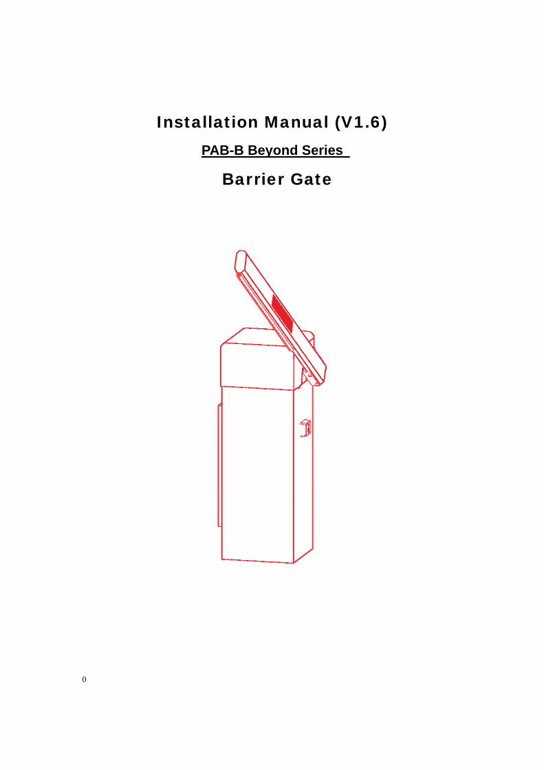
Installation Manual (V1.6)
PAB-B Beyond Series
Barrier Gate
1
Contents
1 Declaration ................................................................................................................. 2
2 Safety………………………………………………………………………………………3~4
3 Packing ...................................................................................................................... 5
4 Installation .............................................................................................................. 6~7
4.1 Structure Of Barrier ......................................................................................... 5
4.2 Arm Installation direction ................................................................................. 6
4.3 Foundation ...................................................................................................... 6
4.4 Power connection ............................................................................................ 7
5 Specification, Feature & Function .........................................................................7~11
5.1 Technical Specification ................................................................................ 7~8
5.2 Function & Features .................................................................................. 8~11
6 Operation ............................................................................................................ 11~14
6.1 Safety tips ...................................................................................................... 11
6.2 Boom arm assembly ....................................................................................... 11
6.3 Adjust the boom length .................................................................................. 12
6.4 Controller Board and wiring Diagram ............................................................ 12
6.5 Parameter programming ............................................................................... 13
6.6 Circuit self-test .............................................................................................. 13
6.7 Manual lock the boom arm ............................................................................ 14
7. Serial control command ...................................................................................... 14~15
8 Maintenance and repair ..................................................................................... 15~16
8.1 Maintenance ............................................................................................ 15~16
8.2 FAQs and troubleshooting ............................................................................. 16
9 Mechanical explosion drawings and parts list ........................................................ 177
10 Block diagram of electrical circuits and control ...................................................... 188
11 Electrical diagram and parts list ......................................................................... 18~19
2
1 Declaration
The original language is English.
Machine noise: less than 60db.
Not more than 1000m above sea level, can not be used in explosive environment.
EU single-phase voltage is 230V.
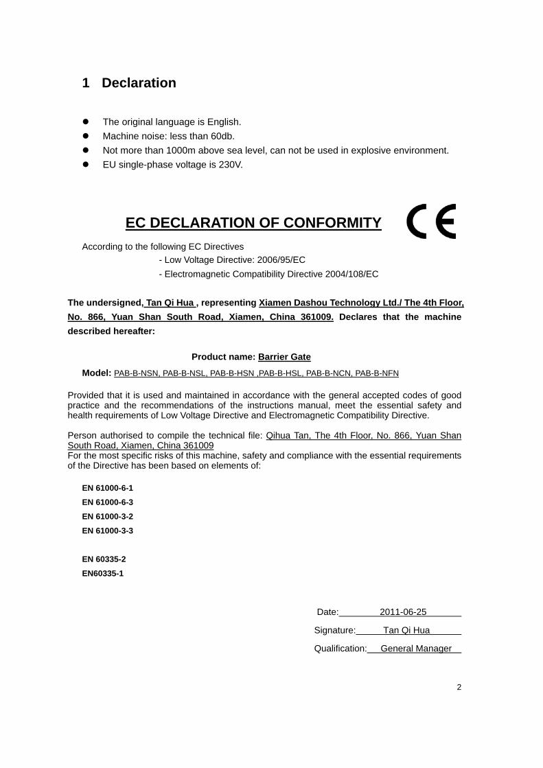
EC DECLARATION OF CONFORMITY According to the following EC Directives
- Low Voltage Directive: 2006/95/EC
- Electromagnetic Compatibility Directive 2004/108/EC
The undersigned, Tan Qi Hua , representing Xiamen Dashou Technology Ltd./ The 4th Floor,
No. 866, Yuan Shan South Road, Xiamen, China 361009. Declares that the machine
described hereafter:
Product name: Barrier Gate
Model: PAB-B-NSN, PAB-B-NSL, PAB-B-HSN ,PAB-B-HSL, PAB-B-NCN, PAB-B-NFN
Provided that it is used and maintained in accordance with the general accepted codes of good practice and the recommendations of the instructions manual, meet the essential safety and health requirements of Low Voltage Directive and Electromagnetic Compatibility Directive. Person authorised to compile the technical file: Qihua Tan, The 4th Floor, No. 866, Yuan Shan South Road, Xiamen, China 361009 For the most specific risks of this machine, safety and compliance with the essential requirements of the Directive has been based on elements of:
EN 61000-6-1
EN 61000-6-3
EN 61000-3-2
EN 61000-3-3
EN 60335-2
EN60335-1
Date: 2011-06-25
Signature: Tan Qi Hua
Qualification: General Manager
3
2 Safety
2.1 General safety information
This PAB-B Beyond series barrier was designed, built and tested using advanced
technology and will have left our factory only after having satisfied stringent safety and
reliability criteria. Nevertheless the barrier system can represent a risk to persons and
property if it is not operated correctly. These operating instructions must therefore be read
in their entirety and all safety information contained therein must be complied with.
The manufacturer shall refuse to accept liability and shall withdraw warranty cover if this
barrier system is used incorrectly or is used for a purpose for which it was not intended.
2.2 Intended Use
The PAB-B Beyond series barriers are designed for use in controlling the entrance and
exit lanes of car parks areas, multi-storey car parks and other vehicular access routes.
It is not permitted to use these barrier systems for any other purpose. Modifications or
changes to the barrier or its control modules are prohibited. Only original Dashou spare
parts and accessories may be used.
2.3 Operational Safety
A safe clearance distance, of at least 500 mm, must be
provided between the tip of the barrier boom and the closest
solid obstacle (building, wall, fence etc.). The barrier activating
elements must be installed at a position that provides a direct
line of site to the barrier.
The motion of the barrier boom must be directly visible to the person operating the barrier.
Whilst the barrier boom is in motion, persons, and other objects, are prohibited from being
in the immediate vicinity of the barrier.
Automated systems must be provided with a specially marked pedestrian walkway (actual
location to be determined on-site).
If the barrier and operating elements have been installed, and connected in a fixed mains
power supply, an all-pole, lockable, electrical master switch must be used.
The assembly and installation instructions must be complied with in their entirety.
4
Permission must be sought from Dashou, prior to any alterations. The barrier boom fixture
is designed to withstand wind velocities of up to a maximum of 10 on the Beaufort scale (=
500 N/m2). If higher wind velocities are anticipated, a modified barrier boom fixture must
first be agreed to by Dashou.
Barrier booms longer than 3.5 m require a supporting bracket.
All electrical connections, wiring work and exchange of any components may only be
performed by appropriately trained electrical technicians.
Before opening any electrical or electronic modules within the barrier, they must first be
disconnected from the mains power supply.
Technical modifications or changes, to the barrier system, are prohibited.
2.4 Technical Developments
The manufacturer reserves the right to modify, without prior notice, the technical
specifications in order to accommodate the latest technical developments. Dashou is
willing to provide information on the status of existing operating instructions and on any
alterations and extensions that may be relevant.
2.5 Warranty
Dashou provides a warranty on its barriers that covers all mechanical and electrical
components, but excludes specific parts subject to wear, for a period of 12 months
warranty from discharging date of shipment, provided that the operating instructions have
been complied with, no unauthorized servicing of machine components has taken place,
and that no mechanical damage to the machines is evident. Warranty does not cover
problems arising after above durations. Besides, the warranty terms agreed between the
distributors and their customers are beyond the liability of DASHOU
5
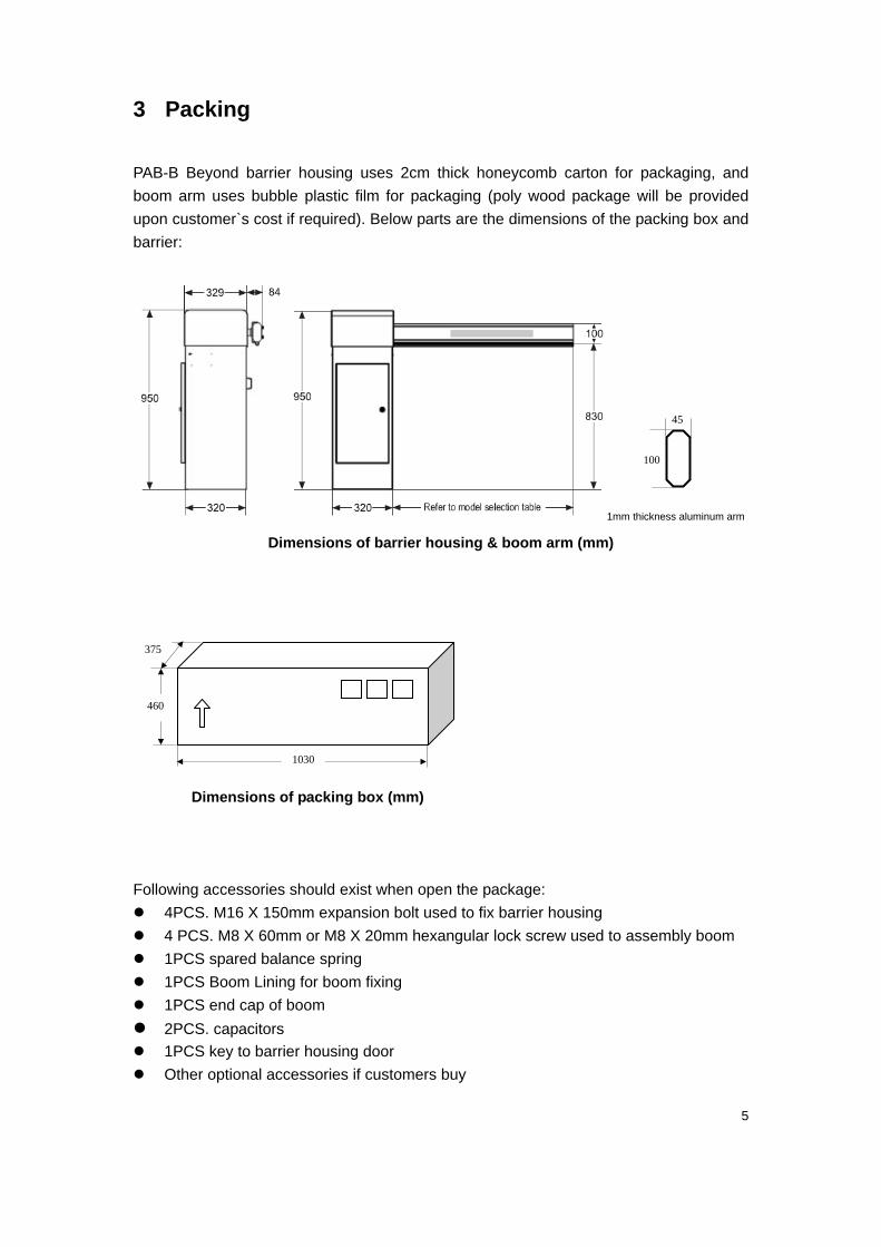
3 Packing
PAB-B Beyond barrier housing uses 2cm thick honeycomb carton for packaging, and
boom arm uses bubble plastic film for packaging (poly wood package will be provided
upon customer`s cost if required). Below parts are the dimensions of the packing box and
barrier:
1mm thickness aluminum arm
Dimensions of barrier housing & boom arm (mm)
Dimensions of packing box (mm)
Following accessories should exist when open the package:
4PCS. M16 X 150mm expansion bolt used to fix barrier housing
4 PCS. M8 X 60mm or M8 X 20mm hexangular lock screw used to assembly boom
1PCS spared balance spring
1PCS Boom Lining for boom fixing
1PCS end cap of boom
2PCS. capacitors 1PCS key to barrier housing door
Other optional accessories if customers buy
1030
460
375
45
100
6
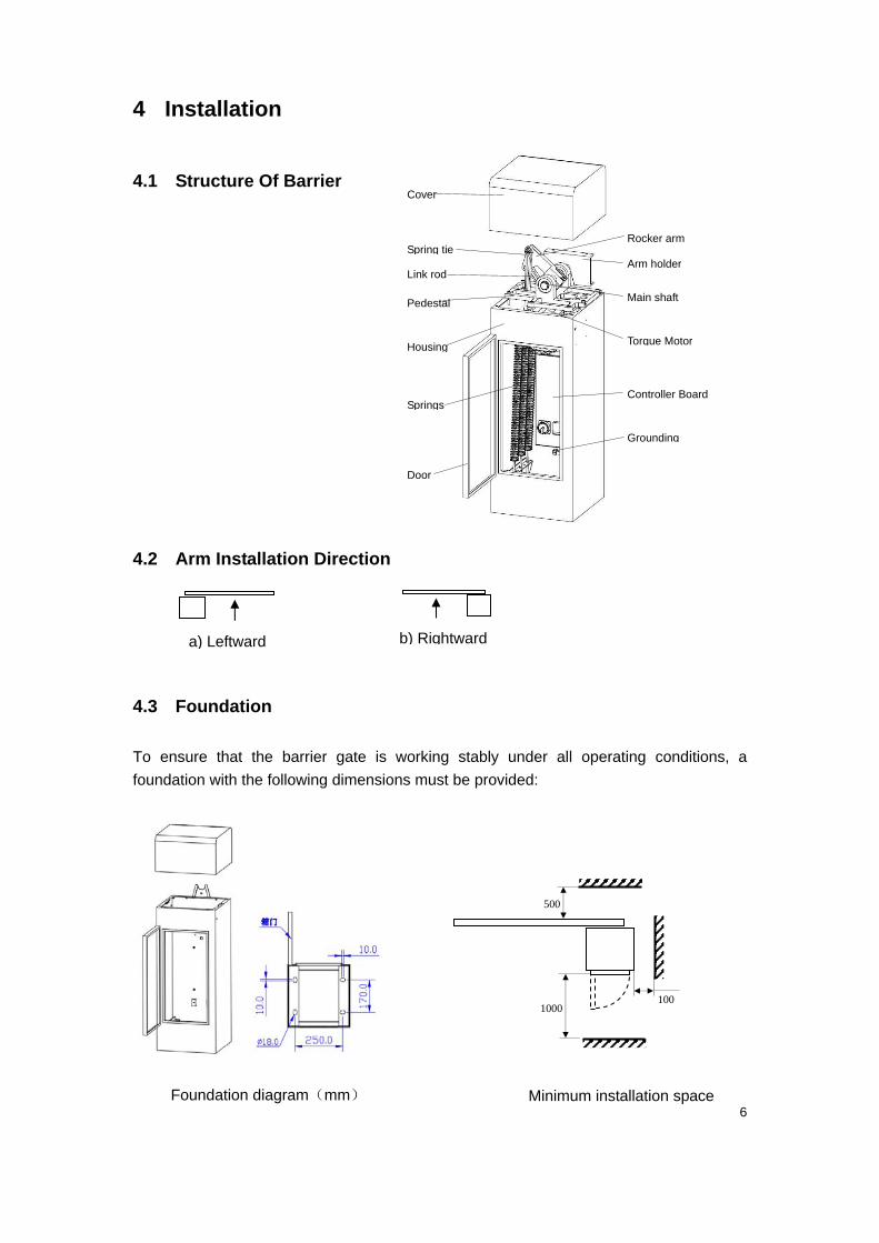
4 Installation
4.1 Structure Of Barrier
4.2 Arm Installation Direction
4.3 Foundation
To ensure that the barrier gate is working stably under all operating conditions, a
foundation with the following dimensions must be provided:
Foundation diagram(mm) Minimum installation space
( )
Cover
Spring tie
Pedestal
Housing
Springs
Door
Rocker arm
Arm holder
Main shaft
Torque Motor
Controller Board
Grounding
Link rod
500
1000100
a) Leftward b) Rightward
7
1. Fix those 4PCS expansion bolt (M16*150) on the concrete island according to above
Foundation Diagram in “4.3 Foundation”;
2. Align the bottom hole of the barrier to those 4PCS expansion bolt, lock and fasten them by nuts.
Please be sure that the barrier can work steady.
4.4 Power Connection
PAB-B Beyond barrier uses AC 220±10% & 50/60HZ input as its power supply. A fuse has
integrated by barrier controller unit. For the safety and ease of maintenance and repair,
barrier has set the auto-breaker and safety switch in power supply circuit.
5 Specification, Features & Function
5.1 Technical specification
Power AC 220±10%, 50/60HZ, Max.0.5A
Motor (AC 220±10%) 70W concreted decelerating torque motor
Control unit Intel 80C51 MCU, 40Mhz basic frequency, controlled silicon motor control, multiplexing
0~5V switch input, multi relay output; RS485 interface, WatchDog shut down protect.
Loop detector input
Either active or passive input; 0~0.5V or short as logic 0, 3V~24V or open as logic 1.
The input has RC hardware filter and 10 ms software filter, the width of pulse required
to be over 100 ms, 1 fall to 0 trig to protect from crash to obstructer, and 0 to 1 trig
barrier boom to move up.
Infrared Photocell input
Either active or passive input, 0~0.5V or short as logic 0, 3V~24V or open as logic 1.
The input has RC hardware filter and 10 ms software filter, the width of pulse required
to be over 100 ms, 1 fall to 0 trig to protect from crash to obstructer, and 0 to 1 trig
barrier boom to move up.
Up & Down input
Either active or passive input, 0~0.5V or short as logic 0, 3V~24V or open as logic 1.
The input has RC hardware filter and 10 ms software filter, the width of pulse required
to be over 100 ms, 1 fall to 0 trig to protect from crash to obstructer, and 0 to 1 trig
barrier boom to move up.
AC220V
L
N
PE
Auto-breake Fuse
Barrier
Safety
8
Traffic light output AC 220V traffic power output, maximum current 0.5A. Barrier boom move >2/3 relay
works and <2/3 release.
Loop detector Syn.output Relay NO output, AC 220V/0.5A, DV 12/1A
Wireless remoter(optional) Two button remote transmitter, distance﹥20m
RS 485 interface Semi-duplex RS485 interface, switch time 10 ms, 8 data bits, 1 stop bit, no checksum,
9600 bps, ASCII decimal code.
Opening/closing time 0.8 / 1.5 / 2 / 3 / 4 second optional
Spring Barrier boom will keep balance in 30~45, >45 will move ‘up’ automatically, <30 will
move ‘down’ automatically
Arm 45×100mm Aluminum alloy, max. 6m
Arm direction Leftward or rightward optional
Housing 2mm cold-roller sheet, anti-UV light and static plating, IP 54
Housing dimension 950mm×329mm×320mm
Gross Weight Around 55 KG
Operating temperature -25 ℃ -55℃
Humidity 10%-95%
5.2 Function & Features
5.2.1 Automatically check the operation status and report failure.
List of failure code as below:
E1---Pulse angle sensor or motor failure;
E3---‘up’ input failure (input remains more than 10 sec. regarding as fail)
E4---‘down’ input failure (input remains more than 10 sec. regarding as fail)
E5---“1# Loop Detector” input failure (input remain more than 10 sec. regarding as fail)
E6---“Infrared photo cell” input failure (input remain more than 10 sec. regarding as fail)
E7---Stop button of remoter transmitter failure (keeping pressing stop button more than 10
sec. regarding as fail)
EF---Always-on mode
5.2.2 Up and Down control
Be able to go up (down) when the barrier boom is moving down (up) without stop
process. Three ways to control the barrier movement:
‘Up’ and ‘Down’ inputs by a push button
Remote control
RS485 serial command.
9
5.2.3 Anti-collision protects boom arm (optional)
Once anti-collision mechanism installed, it will protects the boom arm not to be
damaged once boom arm was collided by a vehicle.
5.2.4 Safety--- Anti-hit by pressure resistance bounce
While moving down, boom arm will immediately go back to vertical position once it is
obstructed by an imposed force, which protects the vehicle or person not to be hit by
boom arm. The sensitivity is adjustable.
Note: This function does not work when the angle is <9 both in vertical and
horizontal position.
5.2.5 Safety--- Anti-hit by Loop Detector (Optional)
Suppose1# loop detector is connected to the barrier gate. While barrier boom moving
down, If a coming vehicle was detected to be existing on the ground induction coil (to
be connected to1# loop detector), the barrier boom will go back to vertical position
immediately until loop input was dismissed and then the barrier boom will go down
immediately.
Note: This function does not work when barrier boom horizontal angle is <9.
5.2.6 Safety--- Anti-hit by IR photocell (Optional)
Suppose a Photo Cell is connected to the barrier gate. While barrier boom moving
down, If infrared transportation between transmitter and receiver is blocked by human
or vehicle, the barrier arm will go back to vertical position immediately. The arm will
automatically close once the infrared transportation recovers.
Note: This function doses not work when barrier boom horizontal angle is <9.
5.2.7 Double safety--- Anti-hit by Loop Detector & IR photocell (Optional)
To double protect a vehicle by connecting a loop detector and a IR photocell to barrier
gate. While barrier boom moving down, if the infrared transportation between
transmitter and receiver was blocked by a coming vehicle, or the coming vehicle was
detected to be existing on the ground induction coil, or both happened, the barrier arm
will go back to vertical position immediately. The arm will automatically & immediately
close once the infrared transportation recovers and at the same time the vehicle has
already passed through the ground induction coil.
5.2.8 Safety--- Anti-hit by “Opening Priority”
If a vehicle is coming while boom arm moving down, the boom arm will immediately go
back to vertical position once a manual open command is given by guard by the push
button or remoter transmitter, which protect the vehicle not to be hit by boom arm.
5.2.9 Closing Priority
While boom arm moving up, the boom arm will immediately go down once a manual
close command is given by guard by the push button or remoter transmitter.
10
5.2.10 Automatically close after the given time
Once this function is set “ON”, the barrier will automatically close after given time
(1-90 seconds adjustable) if there is no vehicle passed after barrier open.
5.2.11 Automatically Close by 1# loop detector (Optional)
If 1# loop detector is connected to barrier gate (connect 1# loop detector to “Loop 1”
terminal of controller board. Refer to 6.4 for details), after vehicle passed the barrier
will automatically close once the loop input was triggered
5.2.12 Automatically open by 2# loop detector (Optional)
If 2# loop detector is connected to barrier gate (connect 2# loop detector to “Loop 2”
terminal of controller board. Refer to 6.4 for details), when barrier boom is in
horizontal position, the barrier boom will go up immediately once the loop input was
triggered
5.2.13 Always-open mode (Optional)
Keep continuously pressing “Stop” button of remote transmitter for 3 seconds, boom
arm will go up to vertical position and stay there until again keep pressing “Close”
button of remoter transmitter for 3 sec. to finish always-open mode.
Or RS485 command was set at always-open mode, the barrier will ignore all ‘close’
command and stay at the vertical position , unless the status changed.
5.2.14 Traffic light control (Optional)
When barrier boom go up more than 2/3, the relay shorted, the port connected to the
green light output will be AC 220V, the port connected to the red light will no output;
When barrier boom go down more than 1/3, the green light will no output, and the red
light output will be AC 220V.
5.2.15 Manually control in case of no power
Once power is off, just open the cabinet and manually control the barrier by a gear
mechanism. Also barrier boom can be manually locked in any position between
horizontal and vertical by pulling out the black plastic “lock/unlock rod” which is
located at the back of motor, the lock status will remain until unlock manually. Push
down the black plastic “lock/unlock rod” to unlock the barrier.
Warning: Not allowed to use the function when power on, may hurt you hand and damage
the motor.
5.2.16 Boom to open up fully or close down in case of power failure (Optional)
If power is suddenly off while boom closing, boom will automatically close down fully if
the angle between boom and vertical plane beyond 45 degree. If power failure occurs
during boom opening, boom will automatically continue to open up fully if the angle
between boom and level surface beyond 45 degrees.
11
5.2.17 Anti-condensation in cold climate
The barrier remains low power consumption even without closing and opening input,
which will keep the motor in normal temperature. The lubricant will not be frozen so
that the barrier will keep working in frozen environment
5.2.18 Transparent plastic covers on Control Board
A transparent plastic covers on the Control Board to makes Control Board water proof
and dust proof, also protects operator.
6 Operation
6.1 Safety tips
Prevent smashing by boom arm: don’t stand under the boom
arm while it is moving down.
Prevent electric shock: barrier using non-secure AC220V as power
supply, the wiring terminals and control board will be electrified with
non-secure voltage after power, don’t touch these parts after power.
Prevent mechanical injury: there are many exposed mechanical parts
will have dislocation movement while barrier is at work. don’t touch
these parts while at work.
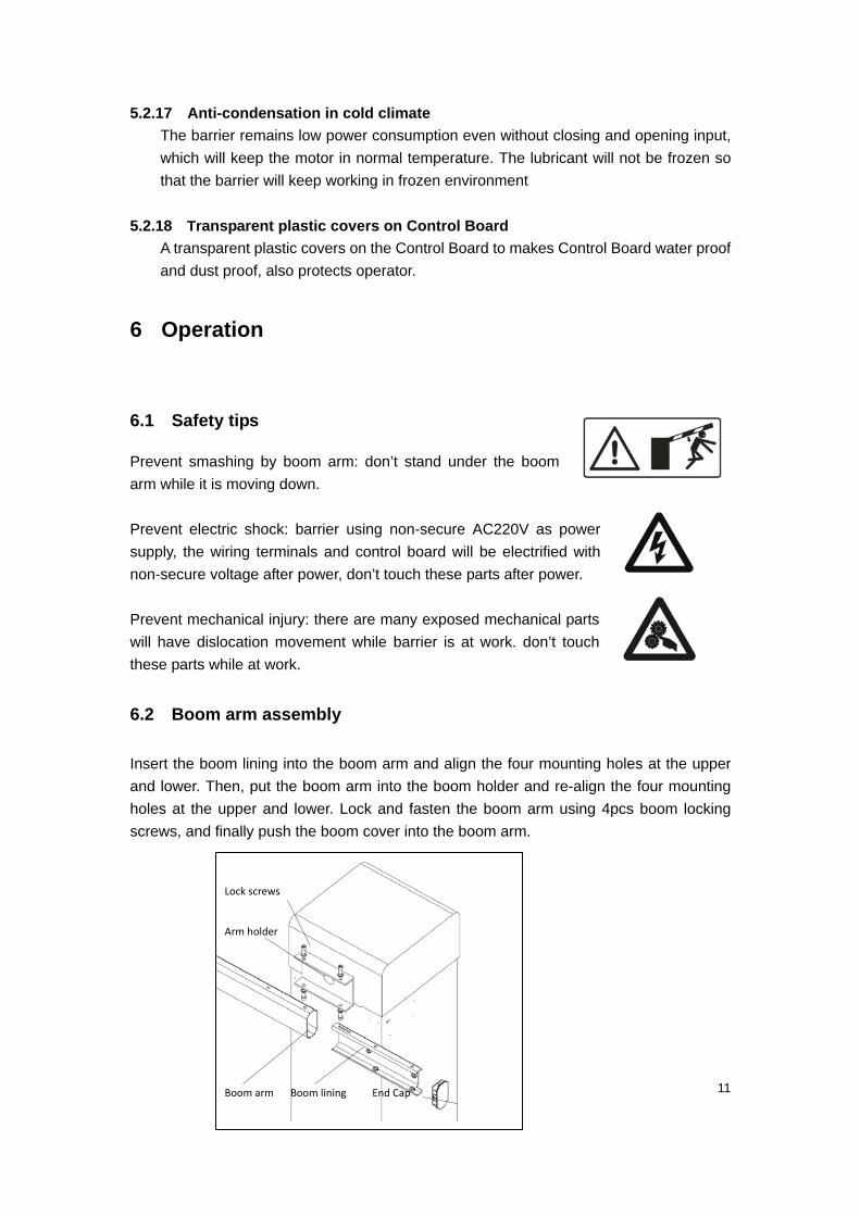
6.2 Boom arm assembly
Insert the boom lining into the boom arm and align the four mounting holes at the upper
and lower. Then, put the boom arm into the boom holder and re-align the four mounting
holes at the upper and lower. Lock and fasten the boom arm using 4pcs boom locking
screws, and finally push the boom cover into the boom arm.
Arm holder
Lock screws
Boom arm Boom lining End Cap
12
6.3 Adjust the boom length
In the factory, boom length and running parameters have been adjusted and programmed
well according to the boom length of customer requirements. If you need re-adjust the
boom length, you must firstly adjust the spring balance and then program the parameters
according to the following steps.
1) Under status of Power-off, remove the boom from the barrier gate and cut boom to
desired length and then assembled to barrier gate.(Refer to 6.2 Boom arm assembly)
2) Power-off the barrier gate, select the appropriate quantity of balance spring
according to boom length and adjust the spring tightness so that the boom can
maintain static balance at 45 degrees.
3) Program parameters: power-on the barrier gate, repeatedly control the barrier up and
down till the barrier gate work steadily. The controller board will automatically adjust
the parameter values till it reaches its optimal level. At first, the boom movement may
not be stable because of inappropriate parameter values, with the up and down times
increasing, the boom movement will be gradually smooth. It means that parameters
have been automatically programmed well when both Up-adjust and Down-adjust
LED indicator goes out.
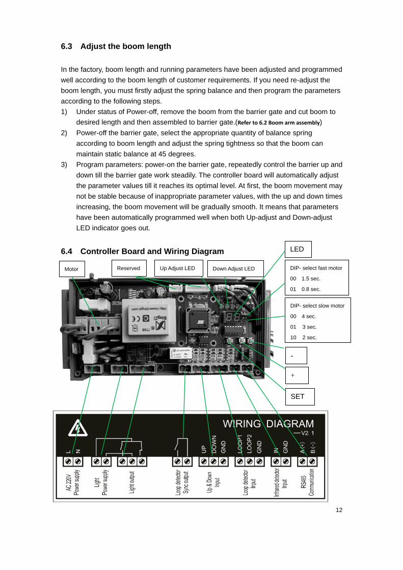
6.4 Controller Board and Wiring Diagram
DIP- select fast motor
00 1.5 sec.
01 0.8 sec.
LED
SET
+
-
DIP- select slow motor
00 4 sec.
01 3 sec.
10 2 sec.
Motor Reserved Up Adjust LED Down Adjust LED
13
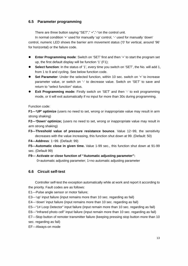
6.5 Parameter programming
There are three button saying “SET”,” +”,”-“on the control unit.
In normal condition ‘+’ used for manually ‘up’ control, ‘-‘ used for manually ‘down’
control, numeric LED shows the barrier arm movement status (‘0’ for vertical, around ‘96’
for horizontal) or the failure code.
Enter Programming mode: Switch on ‘SET’ first and then ‘+’ to start the program set
up, the first default display will be function ‘1’ (F1);
Select function: In the status of ‘1’, every time you switch on ‘SET’, the No. will add 1,
from 1 to 9 and cycling. See below function code.
Set Parameter: Under the selected function, within 10 sec. switch on ‘+’ to increase
parameter value, or switch on ‘-‘ to decrease value. Switch on ‘SET’ to save and
return to “select function” status.
Exit Programming mode: Firstly switch on ‘SET’ and then ‘-‘ to exit programming
mode, or it will exit automatically if no input for more than 30s during programming.
Function code:
F1---‘UP’ optimize (users no need to set, wrong or inappropriate value may result in arm
strong shaking)
F2---‘Down’ optimize; (users no need to set, wrong or inappropriate value may result in
arm strong shaking)
F3---Threshold value of pressure resistance bounce. Value 12~99, the sensitivity
decreases with the value increasing, this function shut down at 99. (Default: 50)
F4---Address: 1~99. (Default: 99)
F5---Automatic close in given time. Value 1-99 sec., this function shut down at 91-99
sec. (Default 99)
F9--- Activate or close function of “Automatic adjusting parameter”:
0=automatic adjusting parameter; 1=no automatic adjusting parameter
6.6 Circuit self-test
Controller self-test the exception automatically while at work and report it according to
the priority. Fault codes are as follows:
E1---Pulse angle sensor or motor failure;
E3---‘up’ input failure (input remains more than 10 sec. regarding as fail)
E4---‘down’ input failure (input remains more than 10 sec. regarding as fail)
E5---“1# Loop Detector” input failure (input remain more than 10 sec. regarding as fail)
E6---“Infrared photo cell” input failure (input remain more than 10 sec. regarding as fail)
E7---Stop button of remoter transmitter failure (keeping pressing stop button more than 10
sec. regarding as fail)
EF---Always-on mode
14
6.7 Manual lock the boom arm
Barrier’s boom arm can be locked in anywhere between horizontal and vertical, pull
out the black plastic “lock/unlock rod” that is at the back of the motor to the locked position
while motor stopped, the boom arm then is locked even if powered. To release the locked
arm, should push in the black plastic “lock/unlock rod” while in power off state.
Warning: Do not use this function under power on, if not, it will make hand injury and
serious motor damages.
7 Serial control command
No-isolate semi-duplex RS485 interface, switch time 10 ms, 8 data bits, 1 stop bit, no
checksum, 9600 bps, ASCII decimal code.
Response time <20 ms(the time between receiving the command and response). The
response defect rate is below 1000 ppm.
“$” is the start character, “!” is the start character of answer, “\r” is the end character of
frame. “00” is the address for broadcasting, only execute no answer.
‘Up’: $AAU\r。AA is the address.
Answer: !AA\r. AA is the address.
‘Down’: $AAD\r AA is the address.
Answer: !AA\r. AA is the address.
Go through mode: $AAP1\r. AA is the address.
Answer: !AA\r. AA is the address.
Exit go through mode: $AAP0\r. AA is the address.
Answer: !AA\r. AA is the address.
Position check: $AAK\r. AA is the address. (Do not support the broadcasting address)
Answer: !AADNN\r. AA is the address. D shows the mode( U ‘up’, D ‘down’ , P ‘go
through’), NN shows the position angle(0~96, 0 is vertical position and 96 is the
horizontal position)
Parameter check: $AARN\r, AA is the address. N is the function number (Do not
support the broadcasting address)
Answer: !AAXX\r. AA is the address. XX is parameter numbers.
Parameter Set up: $AASNXX\r, AA is the address. N N is the function number, XX is
the parameter. (Do not support the broadcasting address)
15
Answer: !AA\r. AA is the address. (Do not support software set up)
Name check: $AAM\r, AA is the address. (Do not support the broadcasting address)
Answer: !AAPAB_B\r. AA is the address. PAB_B is barrier model.
Version check: $AAV\r, AA is the address. (Do not support the broadcasting address)
Answer: !AAXXXYYZZ\r. AA is the address, XXX is the main version number, YY is
no sign character, ZZ is secondary version number.
8. Maintenance and Repair
8.1 Maintenance
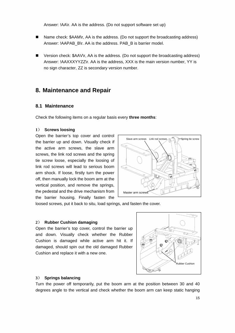
Check the following items on a regular basis every three months:
1) Screws loosing
Open the barrier’s top cover and control
the barrier up and down. Visually check if
the active arm screws, the slave arm
screws, the link rod screws and the spring
tie screw loose, especially the loosing of
link rod screws will lead to serious boom
arm shock. If loose, firstly turn the power
off, then manually lock the boom arm at the
vertical position, and remove the springs,
the pedestal and the drive mechanism from
the barrier housing. Finally fasten the
loosed screws, put it back to situ, load springs, and fasten the cover.
2) Rubber Cushion damaging
Open the barrier’s top cover, control the barrier up
and down. Visually check whether the Rubber
Cushion is damaged while active arm hit it. If
damaged, should spin out the old damaged Rubber
Cushion and replace it with a new one.
3) Springs balancing
Turn the power off temporarily, put the boom arm at the position between 30 and 40
degrees angle to the vertical and check whether the boom arm can keep static hanging
Link rod screws
Master arm screws
Slave arm screws Spring tie screw
Rubber Cushion
16
balance. If can not keep balance, need to adjust the springs balance (Refer to 6.3 Adjust boom
length)
4) Controller Board displaying
While barrier is working, visually check whether the controller Board’s numeral LED
normally displays angle value barrier boom arm moving. If there is fault code displaying,
find the reason and deal it. (Refer to 6.6 Circuit Self‐test)
8.2 FAQs and Troubleshooting
FAQ 1: Turn back halfway while the boom arm is moving down.
Possibility: (1) If F3 value is less than 25, maybe the pressure resistance rebound threshold is too
sensitive, so triggered it by boom inertia or wind blowing.
(2) Maybe springs tension is too tight, so triggered the resistance rebound function.
Solution: (1) Increases the threshold value of pressure resistance rebound to 50.
(2) Reduce the spring tension according to balance adjusting instructions.
FAQ 2: Boom arm move down very slowly and pressure resistance rebound function does not work.
Judging steps: If F2 value is less than 60, maybe springs tension is too loose, lead to down
slow‐down comes too earily.
Solution: Increase the spring tension according to balance adjusting instructions.
FAQ 3: Boom arm shock hardly while it reaches the vertical position and horizon position.
Judging steps: The link‐rod screw is loose.
Solution: Fasten the loosed screws
FAQ 4: Boom jitters up & down continuously for more than 10sec. while it reaches horizon position.
Judging steps: Motor`s starting capacitor becomes old.
Solution: Replace the capacitor with a new one.
FAQ 5: Only can control up, can’t control down.
Judging steps: The Up’s SCR is damaged.
Solution: Replace damaged SCR with a new one.
FAQ 6: Can’t control both up and down, also controller LED display E1 fault code.
Judging steps: 1. If boom rises slowly after power on and controller displays moving angle value,
indicate that the both Up and Down’s SCR are damaged.
2. If boom arm can’t move up after power on and manual moving it can make the
controller display the moving angle value, indicates that the motor is damaged.
3. If boom arm moves up slowly, but controller does not display the moving angle
value, indicates that the pulse angle sensor is damaged.
Solution: 1. Replace damaged SCRs with new one.
2. Replace motor.
3. Replace pulse angle sensor.
17
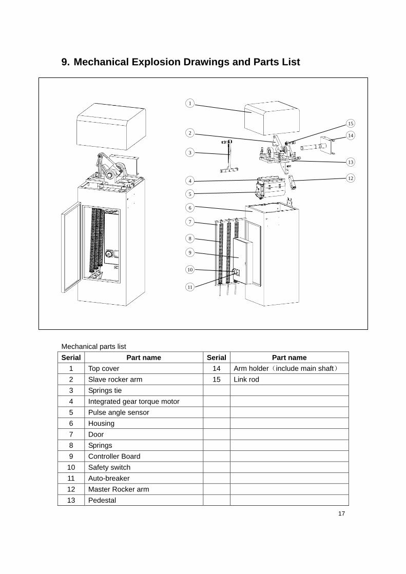
9. Mechanical Explosion Drawings and Parts List
Mechanical parts list
Serial Part name Serial Part name
1 Top cover 14 Arm holder(include main shaft)
2 Slave rocker arm 15 Link rod
3 Springs tie
4 Integrated gear torque motor
5 Pulse angle sensor
6 Housing
7 Door
8 Springs
9 Controller Board
10 Safety switch
11 Auto-breaker
12 Master Rocker arm
13 Pedestal
1
2
3
4
6
7
8
10
11
9
15
14
13
12
5
18
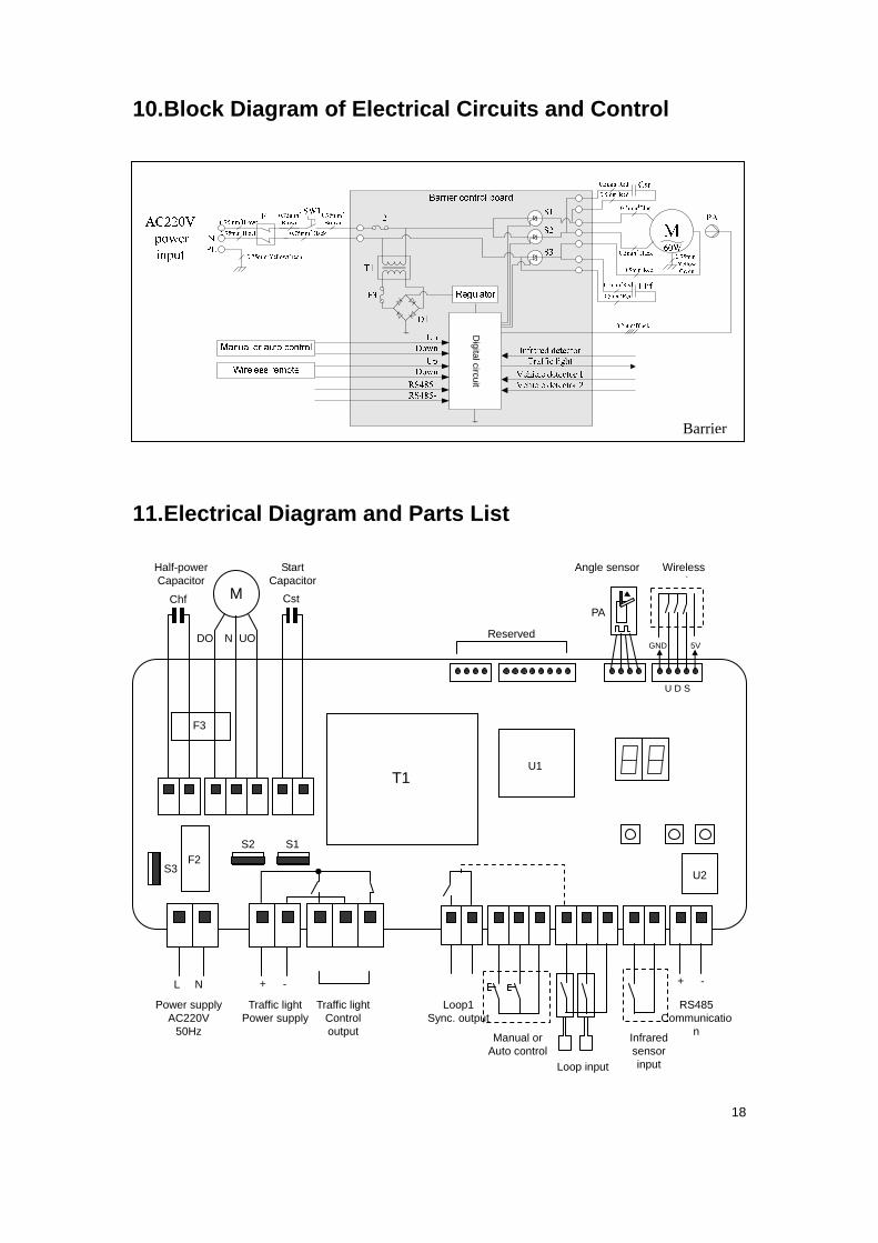
10. Block Diagram of Electrical Circuits and Control
Digital circuit
11. Electrical Diagram and Parts List
Barrier
L N + - + -
GND 5V
U D S
Reserved
M
DO N UO
Chf Cst
Power supply AC220V
50Hz
Traffic light Power supply
Traffic lightControl output
Loop1 Sync. output
Manual orAuto control
Loop input
Infrared sensor input
RS485 Communicatio
n
Half-power Capacitor
Start Capacitor
Angle sensor Wireless recei er
PA
F2 S3
S2 S1
U1
U2
F3
T1

19
Circuit parts list
Code Name Code Name
F1 Auto-breaker Chf Half-power capacitor
SW1 Safety switch Cst Start capacitor
F2 Fuse M Motor
T1 Transformer PA Pulse angle sensor
F3 Fuse U1 MCU IC
D1 Rectifier bridge U2 RS485 transceiver IC
S1 Up SCR
S2 Down SCR
S3 Half-power SCR