Embed Size (px)
Citation preview

Pa
ck
ag
ed
Ga
se
s
Product Catalog
Ensuring cryogenic supply capabilities.Any application - Any time.

Packaged Gases Advantage
Chart’s Packaged Gases are engineered and manufactured to the highest quality standards to provide you with the safest and most reliable equipment available. Driven by innovation, ourpatented cylinder support system and Liquid Cylinder Control Manifold (LCCM) revolutionized theindustry. Experience from understanding our customer’s specifications and the end-use applicationshas made Chart the standard in the industry. When you want the best in packaged gases equipment,our wide range of products are certain to satisfy your requirements while providing the lowest costof ownership.
W h e n y o u c h o o s e C h a r t , y o u g e t s i n g l e - s o u r c e a c c o u n t a b i l i t yf r o m i n i t i a l q u a l i t y t h r o u g h a f t e r t h e s a l e s e r v i c e s u p p o r t .
Engineering Design
Our Packaged Gases equipment designs arebased on integrating patented and proven innovative technologies. Every componentis engineered, built and tested to create the safest and most reliable Packaged Gases equipment available today.
Quality Manufacturing
Our experience and code compliant ISO9001 ensures our liquid cylinders are completed to high quality standards and on time.
Performance
The patented Dura-Cyl design is the perfect blend of plumbing controls,rugged durability and thermal efficiency —giving you the highest performance liquidcylinder package on the market today.
Ensuring cryogenic supply capabilities. Any application - Any time.
2
Production FacilityCanton, Georgia

Packaged Gases
How We Build the Best Liquid Cylinder
3
Simply stated, innovation is the foundation of Chart’s legendary performance, lowest life-cycle cost,safety, and user-friendliness. Each of Chart’s world-leading liquid cylinders has been developed witha commitment to quality, precision engineering and technical excellence.
Handling Ring Large diameter heavy-gauge stainless
steel rolled ring supported with four
brackets for additional strength. Plumbing,
gauges and control valves are well
protected when exposed to rough handling.
Neck TubeOur rugged neck tube is a key component
to our patented Dura-Series support system
design. It is a perfect balance of low heat
loss and durability in event of a tip-over.
Outer ShellOur high-strength high-polish stainless
steel outer shell is a full 12-gauge thickness
for maximum dent resistance for a longer
life quality appearance.
Bottom SupportAnother key component to our patented
Dura-Series support system. The bottom
support not only supports the inner vessel
in the event of a tip-over, but this unique
design prevents the outer top head from
caving if the cylinder is dropped vertically.
FootringOur footring is made of thick 7-gauge
stainless steel and welded 100% to the
bottom head. This all metal, boltless
design helps absorb vertical shock,
promotes cylinder stability and eliminates
maintenance over the cylinder’s life.
LCCMThe patented Liquid Cylinder Control
Manifold (LCCM) reduces plumbing
connections by combining the Economizer
and Pressure Builder (PB) regulator along
with the PB isolation valve. The set
pressure can easily be adjusted by hand
with the calibrated dome control knob.
Load RingThe load ring is another key component
to our patented Dura-Series support system
design. In the event of a tip-over, the
shock is distributed from the outer shell
to the inner vessel through the load ring.
This helps prevent failure of the neck
tube and gives protection in all directions.
Vacuum & InsulationReducing heat transfer from the inner
vessel has always been our top priority.
That’s why we integrate a proprietary spiral
wrap super insulation system with our
vacuum maintenance system. This durable
proven package will give you years of trouble-
free service for maximum NER performance.
Inner VesselEvery step in design, engineering, fabrication
and inspection is directed toward meeting
DOT 4L, TC4LM and other pressure vessel
codes and specifications.
VaporizerWe optimize our vaporizer designs with
the available area of the outer shell to
yield the highest gas withdrawal rates
attainable. During the manufacturing
process, we solder the copper coils to the
inside of the outer shell with custom robotic
machines to maximize the solder content
and control the bonding strength to
achieve our high performance specifications.
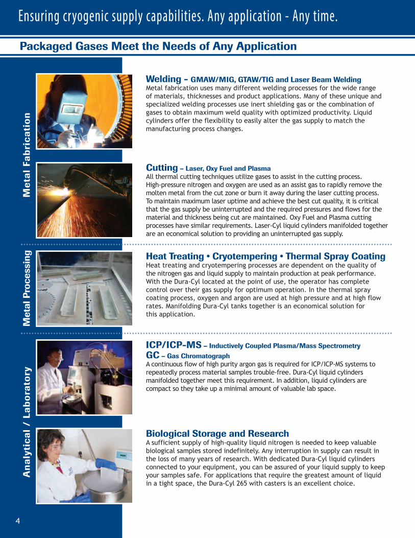
Welding - GMAW/MIG, GTAW/TIG and Laser Beam WeldingMetal fabrication uses many different welding processes for the wide range of materials, thicknesses and product applications. Many of these unique and specialized welding processes use inert shielding gas or the combination of gases to obtain maximum weld quality with optimized productivity. Liquid cylinders offer the flexibility to easily alter the gas supply to match the manufacturing process changes.
Packaged Gases Meet the Needs of Any Application
Ensuring cryogenic supply capabilities. Any application - Any time.
4
Cutting – Laser, Oxy Fuel and PlasmaAll thermal cutting techniques utilize gases to assist in the cutting process. High-pressure nitrogen and oxygen are used as an assist gas to rapidly remove themolten metal from the cut zone or burn it away during the laser cutting process. To maintain maximum laser uptime and achieve the best cut quality, it is critical that the gas supply be uninterrupted and the required pressures and flows for the material and thickness being cut are maintained. Oxy Fuel and Plasma cuttingprocesses have similar requirements. Laser-Cyl liquid cylinders manifolded togetherare an economical solution to providing an uninterrupted gas supply.
ICP/ICP-MS – Inductively Coupled Plasma/Mass SpectrometryGC – Gas ChromatographA continuous flow of high purity argon gas is required for ICP/ICP-MS systems to repeatedly process material samples trouble-free. Dura-Cyl liquid cylinders manifolded together meet this requirement. In addition, liquid cylinders are compact so they take up a minimal amount of valuable lab space.
Biological Storage and ResearchA sufficient supply of high-quality liquid nitrogen is needed to keep valuable biological samples stored indefinitely. Any interruption in supply can result in the loss of many years of research. With dedicated Dura-Cyl liquid cylinders connected to your equipment, you can be assured of your liquid supply to keepyour samples safe. For applications that require the greatest amount of liquid in a tight space, the Dura-Cyl 265 with casters is an excellent choice.
Heat Treating • Cryotempering • Thermal Spray CoatingHeat treating and cryotempering processes are dependent on the quality of the nitrogen gas and liquid supply to maintain production at peak performance.With the Dura-Cyl located at the point of use, the operator has complete control over their gas supply for optimum operation. In the thermal spray coating process, oxygen and argon are used at high pressure and at high flowrates. Manifolding Dura-Cyl tanks together is an economical solution for this application.
Metal Fabrica
tion
Analytica
l / La
boratory
Metal Processing

Packaged Gases
MRI - Magnetic Resonance Imaging (Helium)Superconducting magnets bathed in liquid helium are the most commonly used magnets in an MRI machine. The low temperature reduces the internal resistance to zero, which reduces the electrical requirement for the system dramatically and making it much more economical to operate. Chart’s Ultra Helium Dewars are designed and built for reliable helium transport. They arethermally efficient, lightweight and maneuverable – making them the dewar of choice of lab personnel.
Oxygen Therapy • CryotherapyMedical applications have some of the most stringent gas specifications and the Dura-Cyl meets these requirements with NF grade availability. Dura-Cyls manifolded together for respiratory therapy assures a continuous gas supply and lowers distribution costs over high pressure cylinders. An isolated hyperbaricchamber with intermittent use of oxygen is also a good application for Dura-Cyls.NF grade nitrogen can also be supplied for gas applications to operate pneumaticsurgical tools and supply liquid for medical uses such as cryotherapy.
Purging and BlanketingInert purging and blanketing with nitrogen or argon gas is a common processingstep in many manufacturing applications. These range from pharmaceutical tochemical to wine making. Other unique applications like keeping fiber optic andtelephone wire lines dry with nitrogen throughout the city make the Dura-Cyl anexcellent choice of inert gas supply.
Electronic Manufacturing and TestingElectronics manufacturing can use liquid or gaseous nitrogen or argon during themanufacturing process. Dura-Cyl liquid cylinders offer a compact package where the pressure and source is near the operation for convenience and customization of the gas supply. In a related business, printed circuit board testing (HALT/HASS) performed with liquid nitrogen-powered environmental test chambers requires quality liquid at the point of use. For intermittent users or small chambers, theDura-Cyl is an economical and convenient liquid supply.
Medical
General Proce
ssing
5

Dura-Cyl Benefits:
• Ideal for liquid nitrogen, oxygen, argon, CO2 or nitrous oxide
• Different sizes, pressures, and features to meet your needs
• Stainless steel construction
• Thicker, dent-resistant outer shell
• Patented durable, inner-vessel support system
• Heavy-duty footring and large diameter handling ring with four supports
• Optional Micrometer Controlled Regulator (MCR) or Liquid Cylinder Control Manifold (LCCM)
• Roto-Tel™ Liquid Level Gauge System
• Five-year vacuum warranty
Ensuring cryogenic supply capabilities. Any application - Any time.
6
Dura-Cyl
- -
- --
2
DURA–CYL®
PREMIUM LIQUID CYLINDERS
1
The Dura-Cyl series is a premium transportable
liquid cylinder for cryogenic service. The
patented internal support system design and
quality construction makes the Dura-Cyl series
the most efficient yet rugged cylinder on the
market today. Along with the patented Liquid
Cylinder Control Manifold and our wide choice of
caster base options, the Dura-Cyl Series is also
the most user-friendly cylinder available. Adding
our industry-leading five-year vacuum warranty
and you get the lowest cost of ownership —
making the Dura-Cyl, the preferred choice in
transportable liquid cylinders.
MCR Models have a combinationpressure control regulator with anexclusive, calibrated micrometeradjusting screw. (MP & HP modelsonly)
MODEL 160 L 160 L 180 L 180 L 180 L 200L 200 L 200 LPressure MP HP LP MP HP LP MP HP
LCCM Part Number 10508748 10508756 — 10508764 10496433 — 10508772 10496417
MCR Part Number 10783424 10783467 — 10783491 10783539 — 10783598 10783619
None(1) Part Number — — 10648450 — — 13277869 — —
CAPACITY(2)(3)
Liquid (Gross) (liters) 176 176 196 196 196 209 209 209
Liquid (Net) (liters) 165 165 185 185 185 196 196 196
Gas (N2) ft3 / Nm3 3,685 / 97 3,464 / 91 — 4,099 / 108 3,864 / 102 — 4,375 / 115 4,072 / 108
Gas (O2) ft3 / Nm3 4,577 / 120 4,348 / 114 — 5,096 / 134 4,843 / 127 — 5,435 / 143 5,048 / 133
Gas (Ar) ft3 / Nm3 4,448 / 117 4,226 / 111 — 4,961 / 130 4,709 / 124 — 5,290 / 139 4,932 / 130
Gas (CO2) ft3 / Nm3 — 3,382 / 89 — — 3,766 / 99 — — 4,011 / 105
Gas (N2O) ft3 / Nm3 — 3,207 / 84 — --- 3,574 / 94 — — 3,810 / 100
PERFORMANCENER (N2) % per day 2.0 2.0 1.5 1.9 1.9 1.85 1.85 1.85
NER (02 - Ar) % per day 1.4 1.4 1.0 1.3 1.3 1.2 1.2 1.2
NER (CO2 - N2O) % per day — 0.5 — — 0.5 — — 0.5
Gas Flow (N2, O2, Ar) SCFH/Nm3/hr 350 / 9.2 350 / 9.2 — 350 / 9.2 350 / 9.2 — 400 / 10.5 400 / 10.5
Gas Flow (CO2, N2O) SCFH/Nm3/hr — 110 / 2.9 — — 110 / 2.9 — — 110 / 2.9
DIMENSIONS & PRESSURE RATINGSRelief Valve Setting psig / barg 230 / 16 350 / 24 22 / 1.5 230 / 16 350 / 24 22 / 1.5 230 / 16 350 / 24
DOT/CTC Rating 4L200 4L292 4L100 4L200 4L292 4L100 4L200 4L292
Diameter in / cm 20 / 50.8 20 / 50.8 20 / 50.8 20 / 50.8 20 / 50.8 20 / 50.8 20 / 50.8 20 / 50.8
Height(4) in / cm 59.8 / 151.9 59.8 / 151.9 64.3 / 163.3 64.3 / 163.3 64.3 / 163.3 66.6 / 169.2 66.6 / 169.2 66.6 / 169.2
Tare Weight lb / kg 250 / 113.4 280 / 126.9 210 / 95.2 260 / 117.9 300 / 136.1 210 / 95.2 280 / 126.9 320 / 145.1
Full Weight (N2) lb / kg 517 / 234 531 / 241 540 / 245 557 / 253 580 / 263 559 / 253.5 597 / 271 618 / 280
(O2) lb / kg 629 / 285 640 / 290 676 / 307 682 / 309 701 / 318 706 / 320.2 730 / 331 747 / 339
(Ar) lb / kg 710 / 322 717 / 325 778 / 354 773 / 351 787 / 357 821 / 372.4 827 / 375 839 / 380
(CO2) lb / kg — 667 / 303 — --- 731 / 331 — — 779 / 353
(1) Pressure building regulator optional on LP models. (2) Gas capacities at DOT4L limits. See manual P/N 10642912 for details. NER = Nominal Evaporation Rate(3) Most of the Dura-Cyl models are available with permanently installed CGA fittings for medical applications. Contact Customer Service for details.(4) All dimensions are mea sured fro m the floor to the top of the sight gauge protector.
Footring

7
Packaged Gases
The Roto-Tel™ offers improvedaccuracy and expanded gaugeranges for better resolution.
LCCM Models have an integralmounted combination pressure control regulator, isolation valve and a calibrated dome control knob.(MP & HP models only)
Some models availablewith either round orsquare caster bases forsafe and easy mobility.
Two pull handles are standardon the round base design.
The Dura-Cyl LP models fea-ture the “sight gauge” liquidlevel indicator and a liquidglobe valve with an extendedstem for less ice build-up onthe handle for easier operation.
- -
Nomenclature2
3
8 5, 6, 74
1
PressureBuilding
Coil
- --
2
1. Fill / Liquid Valve.2. Pressure Control Valve.3. Vent Valve.4. Pressure Control Regulator (optional).5. Pressure Gauge.6. Pressure Relief Valve.7. Rupture Disk.8. Liquid Level Gauge.
Model: LP
- -
Nomenclature1
3
4
9 6, 7, 85
2
Vaporizer
PressureBuilding
Coil
- --
2
1. Gas Use Valve.2. Fill / Liquid Valve.3. Pressure Control Valve.4. Vent Valve.5. Combination Pressure Control Regulator.6. Pressure Gauge.7. Pressure Relief Valve.8. Rupture Disk.9. Liquid Level Gauge.
Models: MP & HP
Caster Base
120 L RB 230 L RB 230 L RB 230 L RB 230 L SB 230 L SB 230 L SB 265 L RB 265 L RB 265 L SB 265 L SBLP LP MP HP LP MP HP MP HP MP HP
— — — 10616546 — 10496468 10496492 — — 10510039 10512561
— — 10783635 10783651 — 10810779 10794027 10783678 10783694 — —
10648396 10648599 — — 10648556 — — — — — —
120 240 240 240 240 240 240 276 276 276 276
110 230 230 230 230 230 230 265 265 265 265
— — 5,024 / 132 4,734 / 124 — 5,024 / 132 4,734 / 124 5,769 / 152 5,438 / 143 5,769 / 152 5,438 / 143
— — 6,244 / 164 5,930 / 156 — 6,244 / 164 5,930 / 156 7,186 / 189 6,811 / 179 7,186 / 189 6,811 / 179
— — 6,073 / 160 5,763 / 151 — 6,073 / 160 5,763 / 151 6,982 / 183 6,634 / 174 6,982 / 183 6,634 / 174
— — — 4,614 / 121 — — 4,614 / 121 — 5,305 / 139 — 5,305 / 139
— — — 4,378 / 115 — — 4,378 / 115 — 5,034 / 132 — 5,034 / 132
2.0 1.5 1.8 1.8 1.5 1.8 1.8 2 2 2 2
1.4 1.0 1.2 1.2 1.0 1.2 1.2 1.4 1.4 1.4 1.4
— — — 0.5 — — 0.5 — 0.5 — 0.5
— — 400 / 10.5 400 / 10.5 — 400 / 10.5 400 / 10.5 400 / 10.5 400 / 10.5 400 / 10.5 400 / 10.5
— — — 110 / 2.9 — — 110 / 2.9 — 110 / 2.9 — 110 / 2.9
22 / 1.5 22 / 1.5 230 / 16 350 / 24 22 / 1.5 230 / 16 350 / 24 230 / 16 350 / 24 230 / 16 350 / 24
4L100(5) 4L100 4L200 4L292 4L100 4L200 4L292 4L200 4L292 4L200 4L292
20 / 50.8 26 / 66.0 26 / 66.0 26 / 66.0 26 / 66.0 26 / 66.0 26 / 66.0 26 / 66.0 26 / 66.0 26 / 66.0 26 / 66.0
51 / 129.5 57.2 / 145.3 57.2 / 145.3 57.2 / 145.3 56.8 / 144.3 56.8 / 144.3 56.8 / 144.3 59.9 / 152.2 59.9 / 152.2 59.5 / 151.1 59.5 / 151.1
177 / 80.3 296 / 134.3 311 / 141.1 367 / 166.5 325 / 147.4 340 / 154.2 395 / 179.2 330 / 149.7 390 / 176.9 360 / 163.3 418 / 189.6
377 / 171 697 / 316.2 675 / 306.1 710 / 322 726 / 329.3 704 / 319.3 738 / 334.7 748 / 339.2 784 / 355.6 778 / 352.8 812 / 368.3
462 / 209.5 866 / 392.8 828 / 375.5 858 / 389.1 895 / 406 857 / 388.7 886 / 401.8 925 / 419.5 954 / 432.7 955 / 433.1 982 / 445.4
528 / 239.5 998 / 452.7 939 / 425.9 963 / 436.8 1,027 / 465.8 968 / 439 991 / 449.5 1,052 / 477.1 1,076 / 488 1,082 / 490.7 1,104 / 500.7
— — — 895 / 405.9 — — 923 / 418.6 — 997 / 452.2 — 1,025 / 464.9
RB = Round Base SB = Square Base Note: All caster base models are available with stainless steel casters.
(5) Dura-Cyl 120LP is not TC approved.
Cryo-Cyl Benefits:
• Ideal for liquid nitrogen, oxygen, argon, CO2 or nitrous oxide
• Stainless steel construction
• Thick, dent-resistant outer shell
• Patented durable, inner-vessel support system
• Heavy-duty footring and large diameter handling ring with two supports
• Roto-Tel Liquid Level Gauge System
• Five-year vacuum warranty
Cryo-Cyl
Ensuring cryogenic supply capabilities. Any application - Any time.
8
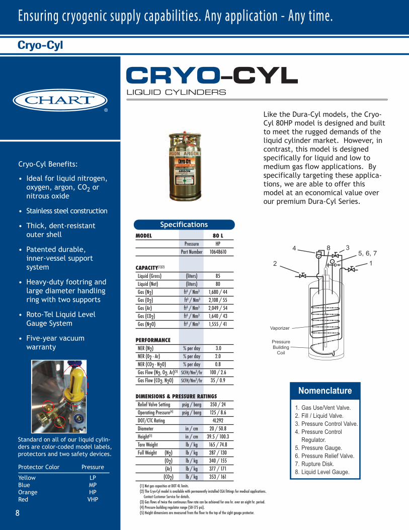
Like the Dura-Cyl models, the Cryo-Cyl 80HP model is designed and builtto meet the rugged demands of theliquid cylinder market. However, in contrast, this model is designedspecifically for liquid and low tomedium gas flow applications. Byspecifically targeting these applica-tions, we are able to offer thismodel at an economical value overour premium Dura-Cyl Series.
CRYO–CYLLIQUID CYLINDERS
Standard on all of our liquid cylin-ders are color-coded model labels,protectors and two safety devices.
Protector Color Pressure
Yellow LPBlue MPOrange HPRed VHP
MODEL 80 LPressure HP
Part Number 10648610
CAPACITY(1)(2)
Liquid (Gross) (liters) 85
Liquid (Net) (liters) 80
Gas (N2) ft3 / Nm3 1,680 / 44
Gas (O2) ft3 / Nm3 2,108 / 55
Gas (Ar) ft3 / Nm3 2,049 / 54
Gas (CO2) ft3 / Nm3 1,640 / 43
Gas (N2O) ft3 / Nm3 1,555 / 41
PERFORMANCENER (N2) % per day 3.0
NER (02 - Ar) % per day 2.0
NER (CO2 - N2O) % per day 0.8
Gas Flow (N2, O2, Ar)(3) SCFH/Nm3/hr 100 / 2.6
Gas Flow (CO2, N2O) SCFH/Nm3/hr 35 / 0.9
DIMENSIONS & PRESSURE RATINGSRelief Valve Setting psig / barg 350 / 24
Operating Pressure(4) psig / barg 125 / 8.6
DOT/CTC Rating 4L292
Diameter in / cm 20 / 50.8
Height(5) in / cm 39.5 / 100.3
Tare Weight lb / kg 165 / 74.8
Full Weight (N2) lb / kg 287 / 130
(O2) lb / kg 340 / 155
(Ar) lb / kg 377 / 171
(CO2) lb / kg 353 / 161
Specifications
(1) Net gas capacities at DOT 4L limits.(2) The Cryo-Cyl model is available with permanently installed CGA fittings for medical applications.
Contact Customer Service for details.(3) Gas flows of twice the continuous flow rate can be achieved for one hr. over an eight hr. period.(4) Pressure building regulator range (50-175 psi).(5) Height dimensions are mea sured fro m the floor to the top of the sight gauge protector.
- -
1
38 5, 6, 7 4
2
Vaporizer
PressureBuilding
Coil
- --
2
- -
Nomenclature1
121-- 4378 / 115
1.8 .81.2 .2
- .5400 / 10.5 400 / 10.5
- 10 / 2.9
230 / 16 350 / 244L200 4L292
26 /66.0 26 /66.056.8 / 144.3 56.8 / 144.3
300 / 136.1 340 / 154.2
664 / 301 683 / 310817 / 370 831 / 377928 / 421 936 / 424
-- 868 / 393
265L SB***265L SB***
MP HP
10510039 10512561
-- --
276 276265 265
5769 / 152 5438 / 1437186 / 189 6811 / 1796982 / 183 6634 / 174
-- 5305 / 139- 5034 / 132
2 21.4 .4
-- 0.5400 / 10.5 400 / 10.5
-- 10 / 2.9
230 / 16 350 / 244L200 4L292
26 /66.0 26 /66.059.5 / 151.1 59.5 / 151.1
340 / 154.2 360 / 163.6
758 / 344 754 / 343935 / 424 924 / 420
1062 / 481 1046 / 475-- 967 / 439
Most of the Dura-Cyl models are available with permanently installed CGA fittings for medical applications. Contact Customer Service for details.
DURA–CYL®
PREMIUM LIQUID CYLINDERS
1. Gas Use/Vent Valve.2. Fill / Liquid Valve.3. Pressure Control Valve.4. Pressure Control Regulator.5. Pressure Gauge.6. Pressure Relief Valve.7. Rupture Disk.8. Liquid Level Gauge.
Packaged Gases
9
Laser-Cyl Benefits:
• Built-in vaporizer coils supply constant pressure gas at continuous flow rates up to 575 SCFH (15.1 Nm3/hr)
• Piping controls located on top for easy operationand maintenance
• Differential pressure liquid level gauge accurately displays product level (450 only)
• Insulation system provides low NER for longer holding time
• Available in 200 and 450 liter sizes with an optional pallet frame
Laser-Cyl
LASER–CYLHIGH PRESSURE LIQUID CYLINDERS
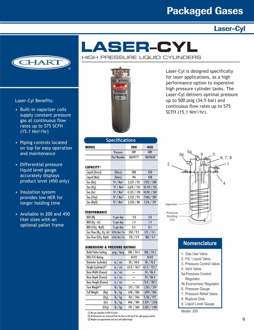
Laser-Cyl is designed specifically for laser applications, as a high performance option to expensivehigh pressure cylinder tanks. TheLaser-Cyl delivers optimal pressureup to 500 psig (34.5 bar) and continuous flow rates up to 575SCFH (15.1 Nm3/hr).
MODEL 200 450Pressure VHP VHP
Part Number 10619771 10619659
CAPACITY(1)
Liquid (Gross) (liters) 200 450
Liquid (Net) (liters) 196 428
Gas (N2) ft3 / Nm3 3,521 / 93 7,922 / 208
Gas (O2) ft3 / Nm3 4,674 / 123 10,519 / 276
Gas (Ar) ft3 / Nm3 4,552 / 120 10,241 / 269
Gas (CO2) ft3 / Nm3 3,537 / 93 7,960 / 209
Gas (N2O) ft3 / Nm3 3,333 / 88 7,516 / 197
PERFORMANCENER (N) % per day 2.0 2.0
NER (02 - Ar) % per day 1.4 1.4
NER (CO2 - N2O) % per day 0.5 0.5
Gas Flow (N2, O2, Ar) SCFH/Nm3/hr 350 / 9.2 575 / 15.1
Gas Flow (CO2, N2O) SCFH/Nm3/hr 110 / 2.9 180 / 4.7
DIMENSIONS & PRESSURE RATINGSRelief Valve Setting psig / barg 500 / 34.5 500 / 34.5
DOT/CTC Rating 4L412 4L412
Diameter (cylinder) in / cm 20 / 50.8 30 / 76.2
Height (cylinder)(2) in / cm 65.8 / 167.1 61.3 / 155.7
Base Width (frame) in / cm — 34 / 86.4
Base Depth (frame) in / cm — 34 / 86.4
Base Height (frame) in / cm — 73.8 / 187.5
Tare Weight(3) lb / kg 375 / 170 1,265 / 574
Full Weight (N2) lb / kg 630 / 286 1,839 / 836
(O2) lb / kg 762 / 346 2,136 / 971
(Ar) lb / kg 846 / 384 2,324 / 1,056
(CO2) lb / kg 791 / 360 2,202 / 1,001
Specifications
SpecificationsMODEL SIZE 160L 160L 180L 180L 200L 200L 230L RB** 230L RB** 265L RB** 265L RB**
Pressure MP HP MP HP MP HP MP HP MP HP
LCCM Part Number 10508748 10508756 10508764 10496433 10508772 10496417 10602822 10616546 -- --
MCR Part Number 10783424 10783467 10783491 10783539 10783598 10783619 10783635 10783651 10783678 10783694
CAPACITYLiquid (Gross) (liters) 176 176 196 196 209 209 240 240 276 276Liquid (Net) (liters) 165 165 185 185 196 196 230 230 265 265Gas (N2)* ft3 / Nm3 3685 / 97 3464 / 91 4099 / 108 3864 / 102 4375 / 115 4072 / 108 5024 / 132 4734 / 124 5769 / 152 5438 / 143Gas (O2)* ft3 / Nm3 4577 / 120 4348 / 114 5096 / 134 4843 / 127 5435 / 143 5048 / 133 6244 / 164 5930 / 156 7186 / 189 6811 / 179Gas (Ar)* ft3 / Nm3 4448 / 117 4226 / 111 4961 / 130 4709 / 124 5290 / 139 4932 / 130 6073 / 160 5763 / 151 6982 / 183 6634 / 174Gas (CO2)* ft3 / Nm3 -- 3382 / 89 -- 3766 / 99 -- 4011 / 105 -- 4614 / 121 -- 5305 / 139Gas (N2O)* ft3 / Nm3 -- 3207 / 84 -- 3574 / 94 -- 3810 / 100 -- 4378 / 115 -- 5034 / 132
PERFORMANCENER (N2) per day 2 2 1.9 1.9 1.85 1.85 1.8 1.8 2 2NER (O2 - Ar) %
% per day 1.4 1.4 1.3 1.3 1.2 1.2 1.2 1.2 1.4 1.4
NER (CO2 - N2O) % per day -- 0.5 -- 0.5 -- 0.5 -- 0.5 -- 0.5Gas Flow (N2, O2, Ar) ft3/hr / Nm3 /hr 350 / 9.2 350 / 9.2 350 / 9.2 350 / 9.2 400 / 10.5 400 / 10.5 400 / 10.5 400 / 10.5 400 / 10.5 400 / 10.5Gas Flow (CO2, N2O) ft3/hr / Nm3 /hr -- 110 / 2.9 -- 110 / 2.9 -- 110 / 2.9 -- 110 / 2.9 -- 110 / 2.9
DIMENSIONS & PRESSURE RATINGS
Relief Valve Setting psig / barg 230 / 16 350 / 24 230 / 16 350 / 24 230 / 16 350 / 24 230 / 16 350 / 24 230 / 16 350 / 24DOT/CTC Rating 4L200 4L292 4L200 4L292 4L200 4L292 4L200 4L292 4L200 4L292Diameter 20 /50.8 20 /50.8 20 /50.8 20 /50.8 20 /50.8 20 /50.8 26 /66.0 26 /66.0 26 /66.0 26 /66.0Height 59.8 / 151.9 59.8 / 151.9 64.3 / 163.3 64.3 / 163.3 66.6 / 169.2 66.6 / 169.2 57.2 / 145.3 57.2 / 145.3 59.9 / 152.2 59.9 / 152.2
Empty Weight 250 / 113.4 280 / 126.9 260 / 117.9 300 / 136.1 280 / 126.9 320 / 145.1 300 / 136.1 340 / 154.2 340 / 154.2 360 / 163.6
Full Weight (N2) 517 / 234 531 / 241 557 / 253 580 / 263 597 / 271 618 / 280 664 / 301 683 / 310 758 / 344 754 / 343(O2) 629 / 285 640 / 290 682 / 309 701/ 318 730 / 331 747 /339 817 / 370 831 / 377 935 / 424 924 / 420(Ar) 710 / 322 717 / 325 773 / 351 787 / 357 827 / 375 839 / 380 928 / 421 936 / 424 1062 / 481 1046 / 475(CO2) -- 667 / 303 -- 731 / 331 -- 779 / 353 -- 868 / 393 -- 967 / 439
Nomenclature1
3
4
9 6, 7, 85b 5a
2
Vaporizer
PressureBuilding
Coil
lb / kg
lb / kgin / cm
in / cm
lb / kglb / kglb / kg
*At relief valve settings **Round caster base ***Square caster base
Note: All dimensions are measured from the floor to the top of the sight gauge protector.
Note: All dimensions are measured from the floor to the top of the sight gauge protector.
230L SB*** 230L SB***
MP HP
10496468 10496492
10810779 10794027
240 240230 230
5024 / 132 4734 / 1246244 / 164 5930 / 1566073 / 160 5763 / 151
-- 4614 / 121-- 4378 / 115
1.8 .81.2 .2
- .5400 / 10.5 400 / 10.5
- 10 / 2.9
230 / 16 350 / 244L200 4L292
26 /66.0 26 /66.056.8 / 144.3 56.8 / 144.3
300 / 136.1 340 / 154.2
664 / 301 683 / 310817 / 370 831 / 377928 / 421 936 / 424
-- 868 / 393
265L SB***265L SB***
MP HP
10510039 10512561
-- --
276 276265 265
5769 / 152 5438 / 1437186 / 189 6811 / 1796982 / 183 6634 / 174
-- 5305 / 139- 5034 / 132
2 21.4 .4
-- 0.5400 / 10.5 400 / 10.5
-- 10 / 2.9
230 / 16 350 / 244L200 4L292
26 /66.0 26 /66.059.5 / 151.1 59.5 / 151.1
340 / 154.2 360 / 163.6
758 / 344 754 / 343935 / 424 924 / 420
1062 / 481 1046 / 475-- 967 / 439
Most of the Dura-Cyl models are available with permanently installed CGA fittings for medical applications. Contact Customer Service for details.
DURA–CYL®
PREMIUM LIQUID CYLINDERS
1. Gas Use Valve.2. Fill / Liquid Valve.3. Pressure Control Valve.4. Vent Valve.5a.Pressure Control Regulator.5b.Economizer Regulator6. Pressure Gauge.7. Pressure Relief Valve.8. Rupture Disk.9. Liquid Level Gauge.
Model: 200
SpecificationsMODEL SIZE 160L 160L 180L 180L 200L 200L 230L RB** 230L RB** 265L RB** 265L RB**
Pressure MP HP MP HP MP HP MP HP MP HP
LCCM Part Number 10508748 10508756 10508764 10496433 10508772 10496417 10602822 10616546 -- --
MCR Part Number 10783424 10783467 10783491 10783539 10783598 10783619 10783635 10783651 10783678 10783694
CAPACITYLiquid (Gross) (liters) 176 176 196 196 209 209 240 240 276 276Liquid (Net) (liters) 165 165 185 185 196 196 230 230 265 265Gas (N2)* ft3 / Nm3 3685 / 97 3464 / 91 4099 / 108 3864 / 102 4375 / 115 4072 / 108 5024 / 132 4734 / 124 5769 / 152 5438 / 143Gas (O2)* ft3 / Nm3 4577 / 120 4348 / 114 5096 / 134 4843 / 127 5435 / 143 5048 / 133 6244 / 164 5930 / 156 7186 / 189 6811 / 179Gas (Ar)* ft3 / Nm3 4448 / 117 4226 / 111 4961 / 130 4709 / 124 5290 / 139 4932 / 130 6073 / 160 5763 / 151 6982 / 183 6634 / 174Gas (CO2)* ft3 / Nm3 -- 3382 / 89 -- 3766 / 99 -- 4011 / 105 -- 4614 / 121 -- 5305 / 139Gas (N2O)* ft3 / Nm3 -- 3207 / 84 -- 3574 / 94 -- 3810 / 100 -- 4378 / 115 -- 5034 / 132
PERFORMANCENER (N2) per day 2 2 1.9 1.9 1.85 1.85 1.8 1.8 2 2NER (O2 - Ar) %
% per day 1.4 1.4 1.3 1.3 1.2 1.2 1.2 1.2 1.4 1.4
NER (CO2 - N2O) % per day -- 0.5 -- 0.5 -- 0.5 -- 0.5 -- 0.5Gas Flow (N2, O2, Ar) ft3/hr / Nm3 /hr 350 / 9.2 350 / 9.2 350 / 9.2 350 / 9.2 400 / 10.5 400 / 10.5 400 / 10.5 400 / 10.5 400 / 10.5 400 / 10.5Gas Flow (CO2, N2O) ft3/hr / Nm3 /hr -- 110 / 2.9 -- 110 / 2.9 -- 110 / 2.9 -- 110 / 2.9 -- 110 / 2.9
DIMENSIONS & PRESSURE RATINGS
Relief Valve Setting psig / barg 230 / 16 350 / 24 230 / 16 350 / 24 230 / 16 350 / 24 230 / 16 350 / 24 230 / 16 350 / 24DOT/CTC Rating 4L200 4L292 4L200 4L292 4L200 4L292 4L200 4L292 4L200 4L292Diameter 20 /50.8 20 /50.8 20 /50.8 20 /50.8 20 /50.8 20 /50.8 26 /66.0 26 /66.0 26 /66.0 26 /66.0Height 59.8 / 151.9 59.8 / 151.9 64.3 / 163.3 64.3 / 163.3 66.6 / 169.2 66.6 / 169.2 57.2 / 145.3 57.2 / 145.3 59.9 / 152.2 59.9 / 152.2
Empty Weight 250 / 113.4 280 / 126.9 260 / 117.9 300 / 136.1 280 / 126.9 320 / 145.1 300 / 136.1 340 / 154.2 340 / 154.2 360 / 163.6
Full Weight (N2) 517 / 234 531 / 241 557 / 253 580 / 263 597 / 271 618 / 280 664 / 301 683 / 310 758 / 344 754 / 343(O2) 629 / 285 640 / 290 682 / 309 701/ 318 730 / 331 747 /339 817 / 370 831 / 377 935 / 424 924 / 420(Ar) 710 / 322 717 / 325 773 / 351 787 / 357 827 / 375 839 / 380 928 / 421 936 / 424 1062 / 481 1046 / 475(CO2) -- 667 / 303 -- 731 / 331 -- 779 / 353 -- 868 / 393 -- 967 / 439
Nomenclature1
3
4
9 6, 7, 85b 5a
2
Vaporizer
PressureBuilding
Coil
lb / kg
lb / kgin / cm
in / cm
lb / kglb / kglb / kg
*At relief valve settings **Round caster base ***Square caster base
Note: All dimensions are measured from the floor to the top of the sight gauge protector.
Note: All dimensions are measured from the floor to the top of the sight gauge protector.
230L SB*** 230L SB***
MP HP
10496468 10496492
10810779 10794027
240 240230 230
5024 / 132 4734 / 1246244 / 164 5930 / 1566073 / 160 5763 / 151
-- 4614 / 121-- 4378 / 115
1.8 .81.2 .2
- .5400 / 10.5 400 / 10.5
- 10 / 2.9
230 / 16 350 / 244L200 4L292
26 /66.0 26 /66.056.8 / 144.3 56.8 / 144.3
300 / 136.1 340 / 154.2
664 / 301 683 / 310817 / 370 831 / 377928 / 421 936 / 424
-- 868 / 393
265L SB***265L SB***
MP HP
10510039 10512561
-- --
276 276265 265
5769 / 152 5438 / 1437186 / 189 6811 / 1796982 / 183 6634 / 174
-- 5305 / 139- 5034 / 132
2 21.4 .4
-- 0.5400 / 10.5 400 / 10.5
-- 10 / 2.9
230 / 16 350 / 244L200 4L292
26 /66.0 26 /66.059.5 / 151.1 59.5 / 151.1
340 / 154.2 360 / 163.6
758 / 344 754 / 343935 / 424 924 / 420
1062 / 481 1046 / 475-- 967 / 439
Most of the Dura-Cyl models are available with permanently installed CGA fittings for medical applications. Contact Customer Service for details.
DURA–CYL®
PREMIUM LIQUID CYLINDERS
1. Gas Use Valve.2. Fill / Liquid Valve.3. Pressure Control Valve.4. Vent Valve.5a.Pressure Control Regulator.5b.Economizer Regulator6. Pressure Gauge.7. Pressure Relief Valve.8. Rupture Disk.9. Liquid Level Gauge.
Model: 200(1) Net gas capacities at DOT 4L limits.(2) All dimensions are mea sured fro m the floor to the top of the sight gauge protector.(3) Weights are approximate and vary with pallet design.
Mega-Cyl Benefits:
• Tough, durable stainlesssteel construction
• High-performance SuperInsulation
• Easily accessible valves and gauges
• Spray header for pump filling on vent tube
• Accurate differential pressure contents gauge(non-electric)
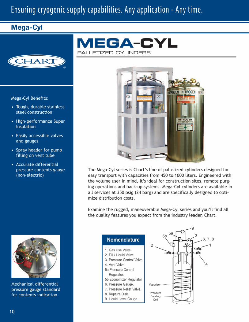
Mechanical differentialpressure gauge standardfor contents indication.
Ensuring cryogenic supply capabilities. Any application - Any time.
10
Mega-Cyl
The Mega-Cyl series is Chart’s line of palletized cylinders designed foreasy transport with capacities from 450 to 1000 liters. Engineered withthe volume user in mind, it’s ideal for construction sites, remote purg-ing operations and back-up systems. Mega-Cyl cylinders are available inall services at 350 psig (24 barg) and are specifically designed to opti-mize distribution costs.
Examine the rugged, maneuverable Mega-Cyl series and you’ll find allthe quality features you expect from the industry leader, Chart.*Atmospheric gas based on net volume at 0 psig, CO
2 values and 450 liter units based on DOT4L fill density.
** Customized pallets are available upon request. *** Weights are approximate and vary with pallet design.
MEGA–CYLPALLETIZED CYLINDERS
SpecificationsModel
Size 450 450 600 800 1000
Pressure MP HP HP HP HP
Part Number 10672951 10588979 11652389 10671262 10752281
CapacityLiquid (Gross) (liters) 450 450 660 880 1056
Liquid (Net)* (liters) 428 428 600 800 950
Gas (N) SCF/Nm3 9,589/252 8,875/233.2 14,755/387.8 19,672/517 23,363/614
Gas (O2 ) SCF/Nm3 11,474/301.5 11,111/ 292 18,240/479.3 24,320/639.1 28,843/758
Gas (Ar) SCF/Nm3 11,003/289.2 10,812/284.1 17,823/468.4 23,767/624.6 28,234/742
Gas (CO2 ) SCF/Nm3 -- 8,652/227.4 12,191/320.4 16,255/427.2 18,580/488.3
PerformanceNER (O
2 )% per day 1.4 1.4 1.2 1.2 0.9
Gas Flow (N, O2 , Ar ) SCFH/Nm3h 575/15.1 575/15.1 750/19.7 880/23.1 960/25.2
Gas Flow (CO2 or N
2 O ) SCFH/Nm3h -- 195/5.1 250/6.6 280/7.4 300/7.9
Dimensions & Pressure RatingsDiameter (cylinder) in/cm 30/76.2 30/76.2 42/106.7 42/106.7 42/106.7
Height (cylinder) in/cm 62/158 62/158 63/159 67/171 76/191
Base Width (frame)** in/cm 34/86.4 34/86.4 45 /114 45/114 45/114
Base Depth (frame)** in/cm 34/86.4 34/86.4 45 /114 45/114 45/114
Height (frame)** in/cm 74/188 74/188 72/183 80/203 80/203
Tare Weight (cyl+frame)*** lb/kg 1250/568 1275/580 1700/773 2500/1136 2650/1205Relief Valve Setting psig/bar 250/17 350/24 350/24 350/24 350/24
DOT/CTC Rating 4L212 4L292 ASME Sec 8/Div1 ASME Sec 8/Div1 ASME Sec 8/Div1
1 2
1 1
1 0
8
9
76
5
4
3
2
1
Nomenclature1. V aporizer 2. Liquid V alve 3. Differential Pressure Guage 4. Economizer Regulator 5. Relief V alve 6. Rupture Disc 7. Pressure Gauge 8. Pressure Building Regulator 9. Pressure Building V alve 10. V ent V alve11 . Gas Use V alve12. Pressure Building Coil
SpecificationsMODEL SIZE 160L 160L 180L 180L 200L 200L 230L RB** 230L RB** 265L RB** 265L RB**
Pressure MP HP MP HP MP HP MP HP MP HP
LCCM Part Number 10508748 10508756 10508764 10496433 10508772 10496417 10602822 10616546 -- --
MCR Part Number 10783424 10783467 10783491 10783539 10783598 10783619 10783635 10783651 10783678 10783694
CAPACITYLiquid (Gross) (liters) 176 176 196 196 209 209 240 240 276 276Liquid (Net) (liters) 165 165 185 185 196 196 230 230 265 265Gas (N2)* ft3 / Nm3 3685 / 97 3464 / 91 4099 / 108 3864 / 102 4375 / 115 4072 / 108 5024 / 132 4734 / 124 5769 / 152 5438 / 143Gas (O2)* ft3 / Nm3 4577 / 120 4348 / 114 5096 / 134 4843 / 127 5435 / 143 5048 / 133 6244 / 164 5930 / 156 7186 / 189 6811 / 179Gas (Ar)* ft3 / Nm3 4448 / 117 4226 / 111 4961 / 130 4709 / 124 5290 / 139 4932 / 130 6073 / 160 5763 / 151 6982 / 183 6634 / 174Gas (CO2)* ft3 / Nm3 -- 3382 / 89 -- 3766 / 99 -- 4011 / 105 -- 4614 / 121 -- 5305 / 139Gas (N2O)* ft3 / Nm3 -- 3207 / 84 -- 3574 / 94 -- 3810 / 100 -- 4378 / 115 -- 5034 / 132
PERFORMANCENER (N2) per day 2 2 1.9 1.9 1.85 1.85 1.8 1.8 2 2NER (O2 - Ar) %
% per day 1.4 1.4 1.3 1.3 1.2 1.2 1.2 1.2 1.4 1.4
NER (CO2 - N2O) % per day -- 0.5 -- 0.5 -- 0.5 -- 0.5 -- 0.5Gas Flow (N2, O2, Ar) ft3/hr / Nm3 /hr 350 / 9.2 350 / 9.2 350 / 9.2 350 / 9.2 400 / 10.5 400 / 10.5 400 / 10.5 400 / 10.5 400 / 10.5 400 / 10.5Gas Flow (CO2, N2O) ft3/hr / Nm3 /hr -- 110 / 2.9 -- 110 / 2.9 -- 110 / 2.9 -- 110 / 2.9 -- 110 / 2.9
DIMENSIONS & PRESSURE RATINGS
Relief Valve Setting psig / barg 230 / 16 350 / 24 230 / 16 350 / 24 230 / 16 350 / 24 230 / 16 350 / 24 230 / 16 350 / 24DOT/CTC Rating 4L200 4L292 4L200 4L292 4L200 4L292 4L200 4L292 4L200 4L292Diameter 20 /50.8 20 /50.8 20 /50.8 20 /50.8 20 /50.8 20 /50.8 26 /66.0 26 /66.0 26 /66.0 26 /66.0Height 59.8 / 151.9 59.8 / 151.9 64.3 / 163.3 64.3 / 163.3 66.6 / 169.2 66.6 / 169.2 57.2 / 145.3 57.2 / 145.3 59.9 / 152.2 59.9 / 152.2
Empty Weight 250 / 113.4 280 / 126.9 260 / 117.9 300 / 136.1 280 / 126.9 320 / 145.1 300 / 136.1 340 / 154.2 340 / 154.2 360 / 163.6
Full Weight (N2) 517 / 234 531 / 241 557 / 253 580 / 263 597 / 271 618 / 280 664 / 301 683 / 310 758 / 344 754 / 343(O2) 629 / 285 640 / 290 682 / 309 701/ 318 730 / 331 747 /339 817 / 370 831 / 377 935 / 424 924 / 420(Ar) 710 / 322 717 / 325 773 / 351 787 / 357 827 / 375 839 / 380 928 / 421 936 / 424 1062 / 481 1046 / 475(CO2) -- 667 / 303 -- 731 / 331 -- 779 / 353 -- 868 / 393 -- 967 / 439
Nomenclature1
3
4
9
6, 7, 85b 5a
2
Vaporizer
PressureBuilding
Coil
lb / kg
lb / kgin / cm
in / cm
lb / kglb / kglb / kg
*At relief valve settings **Round caster base ***Square caster base
Note: All dimensions are measured from the floor to the top of the sight gauge protector.
Note: All dimensions are measured from the floor to the top of the sight gauge protector.
230L SB*** 230L SB***
MP HP
10496468 10496492
10810779 10794027
240 240230 230
5024 / 132 4734 / 1246244 / 164 5930 / 1566073 / 160 5763 / 151
-- 4614 / 121-- 4378 / 115
1.8 .81.2 .2
- .5400 / 10.5 400 / 10.5
- 10 / 2.9
230 / 16 350 / 244L200 4L292
26 /66.0 26 /66.056.8 / 144.3 56.8 / 144.3
300 / 136.1 340 / 154.2
664 / 301 683 / 310817 / 370 831 / 377928 / 421 936 / 424
-- 868 / 393
265L SB***265L SB***
MP HP
10510039 10512561
-- --
276 276265 265
5769 / 152 5438 / 1437186 / 189 6811 / 1796982 / 183 6634 / 174
-- 5305 / 139- 5034 / 132
2 21.4 .4
-- 0.5400 / 10.5 400 / 10.5
-- 10 / 2.9
230 / 16 350 / 244L200 4L292
26 /66.0 26 /66.059.5 / 151.1 59.5 / 151.1
340 / 154.2 360 / 163.6
758 / 344 754 / 343935 / 424 924 / 420
1062 / 481 1046 / 475-- 967 / 439
Most of the Dura-Cyl models are available with permanently installed CGA fittings for medical applications. Contact Customer Service for details.
DURA–CYL®
PREMIUM LIQUID CYLINDERS
1. Gas Use Valve.2. Fill / Liquid Valve.3. Pressure Control Valve.4. Vent Valve.5a.Pressure Control Regulator.5b.Economizer Regulator6. Pressure Gauge.7. Pressure Relief Valve.8. Rupture Disk.9. Liquid Level Gauge.

Packaged Gases
11
MODEL 450 800 1000Pressure HP HP HP
Part Number 10588979 10671262 10752281
CAPACITYLiquid (Gross) (liters) 450 880 1056
Liquid (Net)(1) (liters) 428 800 950
Gas (N2) ft3 / Nm3 8,875 / 233.2 19,672 / 517 23,363 / 614
Gas (O2) ft3 / Nm3 11,111 / 292 24,320 / 639.1 28,843 / 758
Gas (Ar) ft3 / Nm3 10,812 / 284.1 23,767 / 624.6 28,234 / 742
Gas (CO2) ft3 / Nm3 8,652 / 227.4 16,255 / 427.2 18,580 / 488.3
PERFORMANCENER (N2) % per day 2.1 1.8 1.3
NER (02, Ar) % per day 1.4 1.2 0.9
NER (C02, N20) % per day 0.6 0.5 0.3
Gas Flow (N2, O2, Ar) SCFH/Nm3/hr 575 / 15.1 880 / 23.1 960 / 25.2
Gas Flow (CO2) SCFH/Nm3/hr 195 / 5.1 280 / 7.4 300 / 7.9
DIMENSIONS & PRESSURE RATINGSRelief Valve Setting psig / barg 350 / 24 350 / 24 350 / 24
DOT/CTC/ASME Rating 4L292 ASME Sec 8/Div1 ASME Sec 8/Div1
Diameter (cylinder) in / cm 30 / 76.2 42 / 106.7 42 / 106.7
Height (cylinder) in / cm 62 / 158 67 / 171 76 / 191
Base Width (frame)(2) in / cm 34 / 86.4 45 / 114 45 / 114
Base Depth (frame)(2) in / cm 34 / 86.4 45 / 114 45 / 114
Height (frame)(2) in / cm 74 / 188 80 / 203 80 / 203
Tare Wt. (cyl + frame)(3) lb / kg 1,275 / 580 2,500 / 1,136 2,650 / 1,205
Full Weight (N2) lb / kg 1,918 / 872 3,926 / 1,784 4,343 / 1,974
(O2) lb / kg 2,195 / 998 4,514 / 2,052 5,038 / 2,290
(Ar) lb / kg 2,393 / 1,088 4,958 / 2,253 5,569 / 2,532
(CO2) lb / kg 2,265 / 1,029 4,666 / 2,120 5,218 / 2,372
(1) CO2 values and 450 liter models based on DOT4L fill density. N2, O2 and Ar values based on net volume at 0 psig. (2) Customized pallets are available upon request.(3) Weights are approximate and vary with pallet design.
Specifications

12
Ensuring cryogenic supply capabilities. Any application - Any time.
VGL Benefits:
• Ideal for liquid nitrogen,oxygen, argon, CO2 or nitrous oxide
• Stainless steel inner andouter cylinder construc-tion
• Thick, dent-resistant outer shell
• Four handling ring sup-ports with large one-inch pipe size ring
• 4” galvanized casters on 230 models
• Integrated pull handle on 230 square base model
• Color-coded valve han-dles and name tags for easy identification of the plumbing functions
• Roto-Tel Liquid Level Gauge System
• Five-year vacuum warranty
VGLTM Series
The VGLTM is back. Since its first introduc-tion by Minnesota Valley Engineering (MVE)in 1970, the VGL built its reputation on reli-ability and innovation. It was the first liquidcylinder to offer a stainless steel outerjacket, an all-metal shock absorbin foot-ring, and color-coded valve handles. Now,the VGL Series is being reintroduced withupdated components and the latest in field-proven vacuum insulation technology. Themost popular models have been streamlined― making them the preferred choice in economical transportable liquid cylinders.
MODEL 180 200 230 RB 230 SB Pressure HP HP HP HP
PBER Part Number 14880547 14880555 14880563 14880571
CAPACITY(1)(2)
Liquid (Gross) (liters) 196 209 240 240Liquid (Net) (liters) 185 196 230 230Gas (N2) ft3 / Nm3 3,864/102 4,072/108 4,734/124 4,734/124 Gas (O2) ft3 / Nm3 4,843/127 5,048/133 5,930/156 5,930/156 Gas (Ar) ft3 / Nm3 4,709/124 4,932/130 5,763/151 5,763/151 Gas (CO2) ft3 / Nm 3 3,766/99 4,011/105 4,614/121 4,614/121 Gas (N2O) ft3 / Nm3 3,574/94 3,810/100 4,378/115 4,378/115
PERFORMANCE(3)
NER (N2) % per day 1.9 1.85 1.8 1.8NER (02 - Ar) % per day 1.3 1.2 1.2 1.2NER (CO2 - N2O) % per day 0.5 0.5 0.5 0.5Gas Flow (N2, O2, Ar) SCFH/Nm3/hr 350/9.2 400/10.5 400/10.5 400/10.5 Gas Flow (CO2, N2O) SCFH/Nm3/hr 110/2.9 110/2.9 110/2.9 110/2.9
DIMENSIONS & PRESSURE RATINGSRelief Valve Setting psig / barg 350 / 24 350 / 24 350 / 24 350 / 24 DOT Rating 4L292 4L292 4L292 4L292 Diameter in / cm 20 / 50.8 20 / 50.8 26 / 66.0 26 / 66.0Height(4) in / cm 64.3/163.3 66.6/169.2 57.2/145.3 56.8/144.3 Tare Weight lb / kg 288/130 305/138 360/163 393/178 Full Weight (N2) lb / kg 568/257 603/273 703/318 736/333
(O2) lb / kg 689/312 732/332 851/386 884/400 (Ar) lb / kg 775/351 824/373 956/433 989/448(CO2) lb / kg 719/326 764/346 888/402 921/417
(1) Gas capacities at DOT4L limits. See manual for details. (2) All VGL models are available with permanently installed CGA fittings for medicalapplications. Contact Customer Service for details. (3) Ambient conditions: 68°F/20°C and 50% relative humidity(4) Dimensions are mea sured fro m the floor to the top of the sight gauge protector. Note: All caster base models are available with galvanized casters. RB = Round Base SB = Square Base NER=Nominal Evaporation Rate
���� �������� �
7 � !�(�"+.�(%-1% �*%0.+#!*��+45#!*���.#+*���
��� +.�*%0.+1/�+4% !
7� ((�/0�%*(!//�/0!!(�%**!.��* �+10!.��5(%* !.�
�+*/0.1�0%+*
7� �$%�'�� !*0�.!/%/0�*0�+10!.�/$!((
7� �+1.�$�* (%*#�.%*#�/1,,+.0/�3%0$�(�.#!�
+*!�%*�$�,%,!�/%6!�.%*#
7� 9�#�(2�*%6! ���/0!./�+*����)+ !(/
7� �*0!#.�0! �,1((�$�* (!�+*����/-1�.!���/!�
)+ !(
7� �+(+.��+ ! �2�(2!�$�* (!/��* �*�)!�0�#/�"+.��
!�/5�% !*0%"%��0%+*�+"�0$!�,(1)�%*#�"1*�0%+*/
7� �+0+���(��%-1% ��!2!(���1#!��5/0!)
7� �%2!�5!�.�2��11)�3�..�*05
�$!������ %/����'���%*�!�%0/�"%./0�%*0.+ 1�0%+*�
�5��%**!/+0����((!5��*#%*!!.%*#�������%*������
0$!������1%(0�%0/�.!,10�0%+*�+*�.!(%��%(%05��*
%**+2�0%+*���0�3�/�0$!�"%./0�(%-1% ��5(%* !.�0+
+""!.���/0�%*(!//�/0!!(�+10!.�&��'!0���*��((�)!0�(
/$+�'���/+.�%*#�"++0.%*#���* ��+(+.��+ ! �2�(2!
$�* (!/���+3��0$!������!.%!/�%/��!%*#�.!%*0.+�
1�! �3%0$�1, �0! ��+),+*!*0/��* �0$!�(�0!/0
%*�"%!( �,.+2!*�2��11)�%*/1(�0%+*�0!�$*+(+#5�
�$!�)+/0�,+,1(�.�)+ !(/�$�2!��!!*�/0.!�)�
(%*! �:�)�'%*#�0$!)�0$!�,.!"!..! ��$+%�!�%*
!�+*+)%��(�0.�*/,+.0��(!�(%-1% ��5(%* !./�
���������� ������������VERTICAL GAS LIQUID CYLINDERS
�$+%�!�+"�.+1* �+.�/-1�.!���/0!.���/!�+*�0$!����)+ !(/��
�$!��+0+���(8�#�1#!�"!�01.!/��*!�/5�0+�.!� � %�(�(%-1% �(!2!(�%* %��0+.�3%0$�/3%2!(�$!� � !/%#*��
������+ !(/�$�2!����+)�%*�0%+*,.!//1.!��+*0.+(�.!#1(�0+.�"+.�!�/5+,!.�0%*#�,.!//1.!��+*0.+(� 1. Gas Use Valve
2. Fill / Liquid Valve3. Pressure Building Valve4. Vent Valve5. Combination Pressure Building Regulator
6. Pressure Gauge7. Pressure Relief Valve8. Rupture Disk9. Liquid Level Gauge
Nomenclature
Specifications Footring l Caster Base
Packaged Gases
13
CGA Fitting Restraints
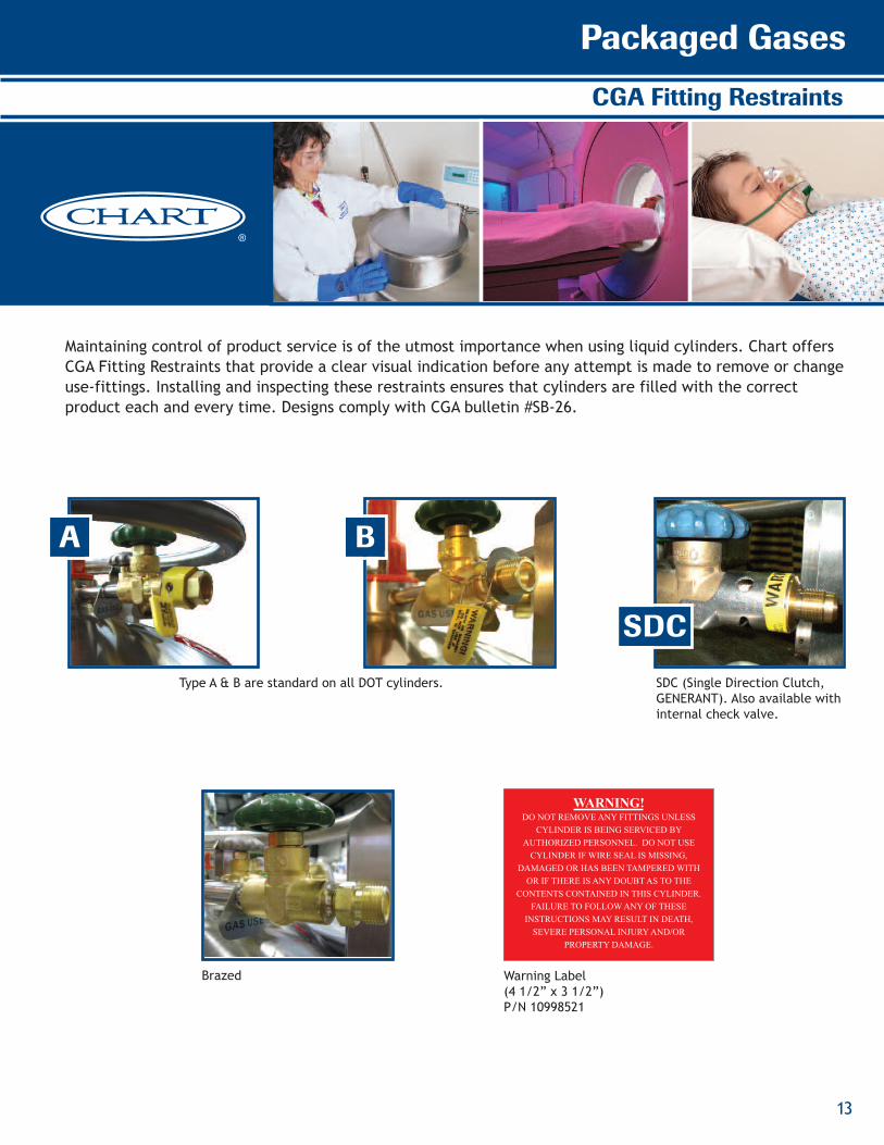
Maintaining control of product service is of the utmost importance when using liquid cylinders. Chart offers CGA Fitting Restraints that provide a clear visual indication before any attempt is made to remove or changeuse-fittings. Installing and inspecting these restraints ensures that cylinders are filled with the correct product each and every time. Designs comply with CGA bulletin #SB-26.
A B
SDC
WARNING!DO NOT REMOVE ANY FITTINGS UNLESS
CYLINDER IS BEING SERVICED BY
AUTHORIZED PERSONNEL. DO NOT USE
CYLINDER IF WIRE SEAL IS MISSING,
DAMAGED OR HAS BEEN TAMPERED WITH
OR IF THERE IS ANY DOUBT AS TO THE
CONTENTS CONTAINED IN THIS CYLINDER.
FAILURE TO FOLLOW ANY OF THESE
INSTRUCTIONS MAY RESULT IN DEATH,
SEVERE PERSONAL INJURY AND/OR
PROPERTY DAMAGE.
Warning Label(4 1/2” x 3 1/2”)P/N 10998521
SDC (Single Direction Clutch,GENERANT). Also available with internal check valve.
Type A & B are standard on all DOT cylinders.
Brazed

Ensuring cryogenic supply capabilities. Any application - Any time.
14
Liquid Cylinder Accessories
M45 Manifold
The M45 manifold is a convenient,automatic way of increasing the gas delivery rate to any application. The unique change-over valve allows easy manual selection of the primary bank ofcylinders. An indicator light showswhen the system switches to thereserve bank so replacementcylinders can be ordered.
Handling Cart
A variety of handling carts andaccessories are available tomake the transportation of liquid cylinders safe and easy.They optimize fast and safe deliveries by decreasing backinjuries, along with loweringWorker’s Compensation costs.
Carriage Cart
The four-wheeled carriage cartpermanently attaches to thelower section of any 20 inch (508mm) diameter liquid cylinder.The front pull handle is attachedto the dual swivel wheels foreasy mobility. Rear wheels arestationary so the carriage cartwith liquid cylinder can bebacked into a tight location.Ideal for lab users with dedicatedliquid cylinders.
Dual Relief Valves
With dual relief valves onecylinder can be used for bothliquid (low pressure) or gas(medium pressure) accounts,which maximizes the flexibilityof your liquid cylinders.
Hose
Stainless-steel transfer hosesthat remain flexible during liquidtransfer can be coupled with abronze phase separator. Ideal for safe discharge of LN2 intoopen dewars.
Vent Muffler
The vent muffler can be attachedto the vent connection of the liquid cylinder to reduce theventing noise during the fill. Plastic for inert service and brass for oxygen service.

Packaged Gases
15
Lo-Loss™
Lo-Loss Benefits:
• Designed for pressure transfer filling in argon, oxygen and nitrogen* service
• Automatic liquid cylinderpressure regulation throughout the fill cycle
• Modular design allows integration into existing systems
• Automatic shutoff improves labor utilizationby allowing unattended filling
• Promotes DOT-compliant filling and eliminates wasted product associatedwith vent filling
* Each product requires a
separate pressure control unit
The Lo-Loss System reduces flash losses during liquid cylinder filling to 3-5% without compromising fill times.For example, flash losses of up to 23%* (1,217 SCF) will occur when filling a 200 liter liquid cylinder in argonservice from a bulk tank at 150 psig (see graph). By maintaining the liquid cylinder vent pressure at 30 psiglower than the bulk tank pressure, Lo-Loss reduces flash losses in this example to 3%* (160 SCF).
* An additional 2-4% of product based on gross volume will be lost due to transfer and cool-down losses.
40
35
30
25
20
15
10
5
0
Depressurization (flash) Losses
Loss
(%)
Bulk Tank Pressure (psig)0 40 80 120 160 200 240
Argon Oxygen Nitrogen
Lo-Loss is an automated fillingsystem that dramatically reduces depressurization (flash) lossesduring liquid cylinder filling. By maintaining an optimal pressuredifference between the bulk tankand liquid cylinder, losses arekept at a minimum without increasing fill times.

Ensuring cryogenic supply capabilities. Any application - Any time.
16
Pro V8 Manifold™
The Pro V8 Manifold is a high-performance liquid cylinder solution for aconsistent gas supply in permanent or temporary applications requiringdelivery pressures up to 450 psig and flow rates up to 2200 SCFH. Whatmakes the Pro V8 unique from other manifolds is that it draws liquid fromup to a total of 8 liquid cylinders into an on-board vaporizer for minimumpressure drop in high flow gas applications, like laser assist gas. The ProV8 provides a constant gas flow by switching between the reserve and pri-mary bank of liquid cylinders until the main supply is finally exhausted.This design minimizes residual losses as it alternates between the reserveand primary banks until the primary bank can no longer supply the re-quired minimum pressure to the application. This patented feature isdriven by a PLC with pressure transducer inputs for high reliability anduser-friendliness. The Pro V8 allows for empty cylinders to be switchedout with no gas supply downtime and at the user’s convenience. Builtusing a painted steel chassis on large pneumatic casters, the Pro V8 iseasily transported and can go anywhere a gas supply is needed − indoorsor outdoors. Works with all pressure ranges of liquid cylinders in gas serv-ice, providing they are of all the same service pressure.
Pro V8 Benefits:
• Service: Nitrogen, Argon, Oxygen or Carbon Dioxide
• Performance Gas Flow*- 1000 SCFH w/3 Liquid
Cylinders- 2200 SCFH w/3 Liquid
Cylinders + 1 Pusher Liquid Cylinder
- Pressure Drop: 5 psig @ 1000 SCFH, 10 psig @ 2200 SCFH**
•Capacity - 6 Liquid Cylinders + 2
Pusher LCs (4 per bank)
- Compatibility Models: MP, HP or Laser-CylTM
•Rugged painted steel com-pact frame design for easy delivery and set up for temporary applications
•Fits through standard 34” door, straps down easily in standard pickup truck and includes lifting lug for overhead crane
•Large, 8” diameter pneu-matic tires for outdoor installations
* Measured at 70˚F and 50% relative humidity with nitrogen.
**Measured between liquid cylinder top head and ambient vaporizer output.

Packaged Gases
17
Argon Maximizer Benefits:
• Reduce liquid cylinder filllosses by as much as 73%*
• Increase customer satisfaction with longer hold times (40 hours on average)
• Reduce liquid cylinder fill time labor
• Eliminate just-in-time liquid cylinder filling
*Contact Chart for a customized economic analysis for details.
The Argon Maximizer is an efficient cryogenic heat exchanger designed to reduce filling losses in argon liquid cylinders. It operates with a simple heattransfer principle that consumes inexpensive liquidnitrogen to subcool the argon during the liquid cylinder filling process. The results are lower liquidcylinder filling losses and colder liquid for longerholding times — giving you better handling logisticsat your fill plant and at your customer’s site. TheArgon Maximizer can also be used with Lo-Loss tofurther optimize the filling process.
Argon Maximizer™/Ultra-Helium Dewars
ARGON MAXIMIZER™
LIQUID CYLINDER FILLING SYSTEM
ULTRA–HELIUM DEWARSBUILT FOR RELIABLE TRANSPORT
Nomenclature 1. Quick Coupling Stack 2. Liquid Valve 3. Handle Assembly 4. Swivel Caster Non-Magnetic 5. Rigid Caster Non-Magnetic 6. Vent Valve Connection 7. V-Band Clamp 8. Aux. Relief Isolation Valve 9. Aux. Relief Valve
1.0 psig (.07 barg) 10. Pressure Gauge 11. Secondary Relief Valve
12 psig (.8 barg) 12. Main Relief Valve
13. Main Vent Valve 10 psig (.7 barg)
Model
Size 60 100 250 500 1000
Part Number 10533409 10533417 9923629 11202581 10801581
Capacity
Liquid (Gross) (liters) 110 66 275 550 1,050
Liquid (Net) (liters) 60 100 250 500 1,000
Performance
NER ** % per day 1.75 1.25 1.0 1.0 1.0
MAWP psig/bar 10.0/0.7 10.0/0.7 10.0/0.7 10.0/0.7 10.0/0.7
Dimensions & Pressure Ratings
Diameter in/ cm 24.0/61.0 24.0/61.0 32.0/81.3 42.0/106.7 52.0/132.1
Height in/ cm 50.1/127.3 59.0/147.9 67.4/171.1 70.6/179.3 77.4/196.6
Dip Tube Length* in/ cm 35.0/88.9 43.8/111.1 54.4/138.2 56.4/143.1 67.5/170.9
Tare Weight lb/ kg 184.0/83.0 212.0/96.0 348.0/158.0 480.0/218.0 1,050.0/476.0
Main Relief Valve Setting psig/ bar 10.0/0.7 10.0/0.7 10.0/0.7 10.0/0.7 10.0/0.7
Secondary Relief Valve psig/ bar 12.0/0.8 12.0/0.8 12.0/0.8
350
10570445
368
350
1.0
10.0/0.7
32.0/81.3
72.5/184.2
55.5/141.0
380.0/172.0
10.0/0.7
12.0/0.8 12.0/0.8 12.0/0.8
Contact Customer Service for a full line of Helium Accessories
*The dip tube length is measured from the tank flange to the bottom of the inner vessel. ** Based on gross capacity
Specifications
*
The Ultra Helium Dewars are de-signed and built for reliable trans-port. They are light, maneuverableand durable, while providing superiorthermal performance. The uniqueneck tube design provides provensupport during transportation. Theoutboard caster base provides maxi-mum stability in a compact design.
Model 250 LModel 100 LModel 60 L
MODEL 60 100 250 500Part Number 10533409 10533417 9923629 11202581
CAPACITY(1)
Liquid (Gross) (liters) 66 110 275 550
Liquid (Net) (liters) 60 100 250 500
PERFORMANCENER(2) % per day 1.75 1.25 1.0 1.0
MAWP psig / barg 10.0 / 0.7 10.0 / 0.7 10.0 / 0.7 10.0 / 0.7
DIMENSIONS & PRESSURE RATINGSRelief Valve Setting psig / barg 10.0 / 0.7 10.0 / 0.7 10.0 / 0.7 10.0 / 0.7
Secondary Relief Valve psig / barg 12.0 / 0.8 12.0 / 0.8 12.0 / 0.8 12.0 / 0.8
Diameter in / cm 24.0 / 61.0 24.0 / 61.0 32.0 / 81.3 42.0 / 106.7
Height in / cm 49.5 / 125.7 56.5 / 143.5 67.4 / 171.1 67.25 / 170.8
Dip Tube Length(1) in / cm 32.5 / 82.6 39.5 /100.3 54.4 / 138.2 51.5 / 98.1
Tare Weight lb / kg 184 / 83 212 / 96 348 / 158 470 / 213.2
(1) The dip tube length is measured from the tank flange to the bottom of the inner vessel.(2) Based on gross capacity.Contact Customer Service for a full line of Helium Accessories.
Specifications
ULTRA-HELIUM DEWARSBUILT FOR RELIABLE TRANSPORT
Ensuring cryogenic supply capabilities. Any application - Any time.
18
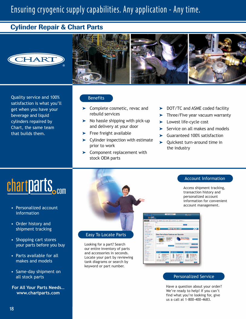
Cylinder Repair & Chart Parts
Quality service and 100%
satisfaction is what you’ll
get when you have your
beverage and liquid
cylinders repaired by
Chart, the same team
that builds them.
➤ Complete cosmetic, revac and rebuild services
➤ No hassle shipping with pick-up and delivery at your door
➤ Free freight available
➤ Cylinder inspection with estimateprior to work
➤ Component replacement with stock OEM parts
➤ DOT/TC and ASME coded facility
➤ Three/Five year vacuum warranty
➤ Lowest life-cycle cost
➤ Service on all makes and models
➤ Guaranteed 100% satisfaction
➤ Quickest turn-around time inthe industry
Benefits
Personalized Service
Account Information
Easy To Locate Parts
Access shipment tracking,transaction history and personalized account information for convenient account management.
Have a question about your order?We’re ready to help! If you can’tfind what you’re looking for, giveus a call at 1-800-400-4683.
Looking for a part? Search our entire inventory of partsand accessories in seconds.Locate your part by reviewingtank diagrams or search by keyword or part number.
• Personalized account information
• Order history and shipment tracking
• Shopping cart stores your parts before you buy
• Parts available for all makes and models
• Same-day shipment on all stock parts
For All Your Parts Needs…
www.chartparts.com
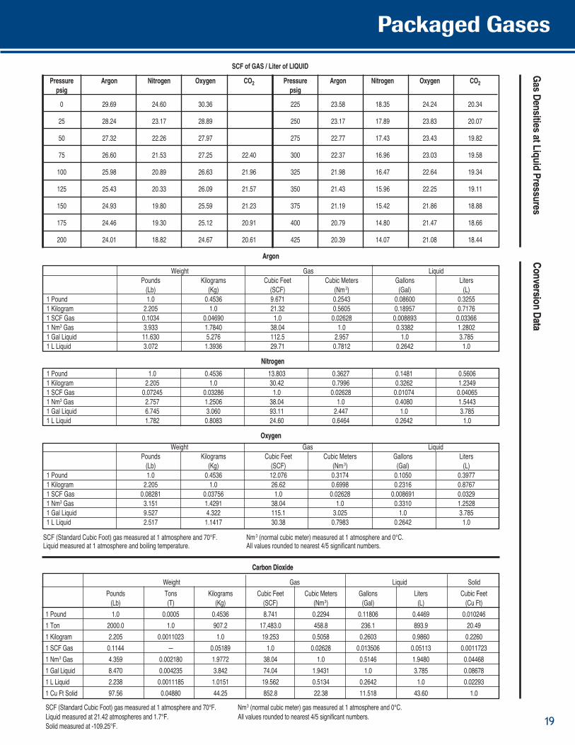
Pressure Argon Nitrogen Oxygen CO2 Pressure Argon Nitrogen Oxygen CO2psig psig
0 29.69 24.60 30.36 225 23.58 18.35 24.24 20.34
25 28.24 23.17 28.89 250 23.17 17.89 23.83 20.07
50 27.32 22.26 27.97 275 22.77 17.43 23.43 19.82
75 26.60 21.53 27.25 22.40 300 22.37 16.96 23.03 19.58
100 25.98 20.89 26.63 21.96 325 21.98 16.47 22.64 19.34
125 25.43 20.33 26.09 21.57 350 21.43 15.96 22.25 19.11
150 24.93 19.80 25.59 21.23 375 21.19 15.42 21.86 18.88
175 24.46 19.30 25.12 20.91 400 20.79 14.80 21.47 18.66
200 24.01 18.82 24.67 20.61 425 20.39 14.07 21.08 18.44
Nitrogen
1 Pound 1.0 0.4536 13.803 0.3627 0.1481 0.5606
1 Kilogram 2.205 1.0 30.42 0.7996 0.3262 1.2349
1 SCF Gas 0.07245 0.03286 1.0 0.02628 0.01074 0.04065
1 Nm3 Gas 2.757 1.2506 38.04 1.0 0.4080 1.5443
1 Gal Liquid 6.745 3.060 93.11 2.447 1.0 3.785
1 L Liquid 1.782 0.8083 24.60 0.6464 0.2642 1.0
Oxygen
Weight Gas Liquid
Pounds Kilograms Cubic Feet Cubic Meters Gallons Liters
(Lb) (Kg) (SCF) (Nm3) (Gal) (L)
1 Pound 1.0 0.4536 12.076 0.3174 0.1050 0.3977
1 Kilogram 2.205 1.0 26.62 0.6998 0.2316 0.8767
1 SCF Gas 0.08281 0.03756 1.0 0.02628 0.008691 0.0329
1 Nm3 Gas 3.151 1.4291 38.04 1.0 0.3310 1.2528
1 Gal Liquid 9.527 4.322 115.1 3.025 1.0 3.785
1 L Liquid 2.517 1.1417 30.38 0.7983 0.2642 1.0
SCF (Standard Cubic Foot) gas measured at 1 atmosphere and 70°F. Nm3 (normal cubic meter) measured at 1 atmosphere and 0°C.Liquid measured at 1 atmosphere and boiling temperature. All values rounded to nearest 4/5 significant numbers.
Gas D
ensities at Liquid PressuresConversion D
ata
Carbon Dioxide
Weight Gas Liquid Solid
Pounds Tons Kilograms Cubic Feet Cubic Meters Gallons Liters Cubic Feet
(Lb) (T) (Kg) (SCF) (Nm3) (Gal) (L) (Cu Ft)
1 Pound 1.0 0.0005 0.4536 8.741 0.2294 0.11806 0.4469 0.010246
1 Ton 2000.0 1.0 907.2 17,483.0 458.8 236.1 893.9 20.49
1 Kilogram 2.205 0.0011023 1.0 19.253 0.5058 0.2603 0.9860 0.2260
1 SCF Gas 0.1144 — 0.05189 1.0 0.02628 0.013506 0.05113 0.0011723
1 Nm3 Gas 4.359 0.002180 1.9772 38.04 1.0 0.5146 1.9480 0.04468
1 Gal Liquid 8.470 0.004235 3.842 74.04 1.9431 1.0 3.785 0.08678
1 L Liquid 2.238 0.0011185 1.0151 19.562 0.5134 0.2642 1.0 0.02293
1 Cu Ft Solid 97.56 0.04880 44.25 852.8 22.38 11.518 43.60 1.0
SCF (Standard Cubic Foot) gas measured at 1 atmosphere and 70°F. Nm3 (normal cubic meter) gas measured at 1 atmosphere and 0°C.
Liquid measured at 21.42 atmospheres and 1.7°F. All values rounded to nearest 4/5 significant numbers.
Solid measured at -109.25°F.
Argon
Weight Gas Liquid
Pounds Kilograms Cubic Feet Cubic Meters Gallons Liters
(Lb) (Kg) (SCF) (Nm3) (Gal) (L)
1 Pound 1.0 0.4536 9.671 0.2543 0.08600 0.3255
1 Kilogram 2.205 1.0 21.32 0.5605 0.18957 0.7176
1 SCF Gas 0.1034 0.04690 1.0 0.02628 0.008893 0.03366
1 Nm3 Gas 3.933 1.7840 38.04 1.0 0.3382 1.2802
1 Gal Liquid 11.630 5.276 112.5 2.957 1.0 3.785
1 L Liquid 3.072 1.3936 29.71 0.7812 0.2642 1.0
SCF of GAS / Liter of LIQUID
Packaged Gases
19
Phone1-800-400-4683
Fax1-952-758-8275
Worldwide1-952-758-4484
Chart Inc.407 Seventh Street NWNew Prague, MN 56071
www.chartindustries.com
©2013 Chart Inc.
P/N 13962022